| Part Number |
00YJ776 |
00YJ777 |
00YJ778 |
00YJ779 |
| Feature Code |
ATZY |
ATZZ |
AU00 |
ATZX |
| Region |
North America |
International |
International |
North America |
| Input power |
| Number of phases |
Single phase input |
Three phase input |
| Line cord |
Attached line cord, 3 m length (9-ft, 10-in) |
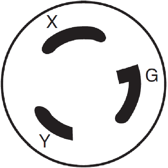
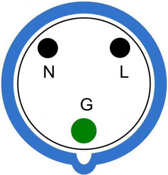
| Line cord connector |
NEMA L6-30P |
332P6, W+N+PE 1ph |
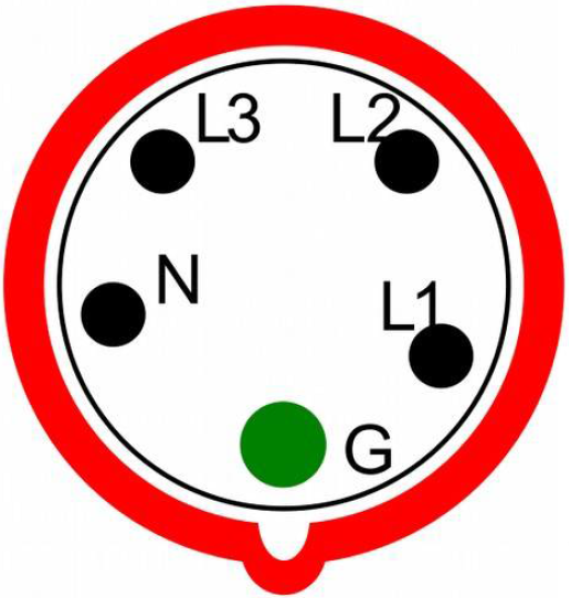
532P6, WYE, 3W+N+PE 3Ph |
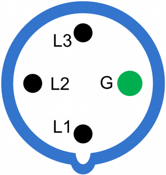
HBL460P9, Delta 3W+PE 3ph |
| Plug design |
 |
 |
 |
 |
| Input voltage |
200-240V |
200-240V |
200-240V / 350-415V |
200-240V |
| Input current |
24A (derated from 30A) |
32A |
32A |
48A (derated from 60A) |
| Maximum power rating |
5760 VA |
7680 VA |
23,040 VA |
20,736 VA |
| Output power |
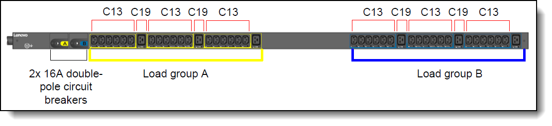
| Number of C13 outlets |
36 |
36 |
21 |
21 |
| Number of C19 outlets |
6 |
6 |
12 |
12 |
| Output voltage rating at 50/60Hz |
200-240V |
200-240V |
200-240V |
200-240V |
| Output current rating |
Each C13 outlet: 10 amps; Each C19 outlet: 16 amps |
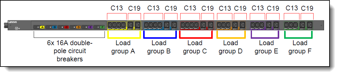
| Circuit breakers |
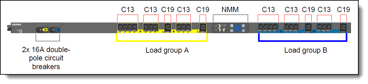
Two double-pole branch rated circuit breakers rated at 16A |
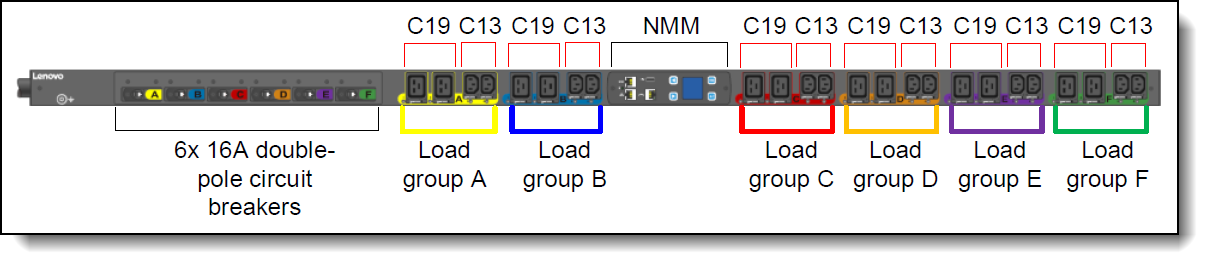
Six double-pole branch rated circuit breakers rated at 16A |
| Number of load groups |
2 (A, B) |
2 (A, B) |
6 (A-F) |
6 (A-F) |
| Number of outlets per load group |
A = 18x C13, 3x C19
B = 18x C13, 3x C19 |
A = 18x C13, 3x C19
B = 18x C13, 3x C19 |
A = 4x C13, 2x C19
B = 4x C13, 2x C19
C = 4x C13, 2x C19
D = 3x C13, 2x C19
E = 3x C13, 2x C19
F = 3x C13, 2x C19 |
A = 4x C13, 2x C19
B = 4x C13, 2x C19
C = 4x C13, 2x C19
D = 3x C13, 2x C19
E = 3x C13, 2x C19
F = 3x C13, 2x C19 |
| Capacity per load group (Amps) |
A = 20 A
B = 20 A |
A = 16 A
B = 16 A |
A = 20 A
B = 20 A
C = 20 A
D = 16 A
E = 16 A
F = 16 A |
A = 20 A
B = 20 A
C = 20 A
D = 20 A
E = 20 A
F = 20 A |
| Capacity per phase (Amps) |
Not applicable |
Not applicable |
Phase 1:
A + D = 32 A
Phase 2:
B + E = 32 A
Phase 3:
C + F = 32 A |
Phase 1:
A + D = 32 A
Phase 2:
B + E = 32 A
Phase 3:
C + F = 32 A |
| Capacity per PDU (Amps) |
24 A |
32 A |
96 A |
86 A |
| Mechanical and environmental |
| Physical dimensions (DxWxH) |
2.5 x 2.0 x 66.4 in
66 x 52 x 1689 mm |
2.5 x 2.0 x 66.4 in
66 x 52 x 1689 mm |
3.0 x 2.0 x 66.4 in
77 x 52 x 1689 mm |
3.8 x 2.0 x 66.4 in
99 x 52 x 1689 mm |
| Weight |
4 kg / 8.8 lb. |
4 kg / 8.8 lb. |
5.3 kg / 11.6 lb. |
8.7 kg / 19.1 lb. |
| Operating temperature |
10° C to 55° C
50° F - 122° F |
10° C to 60° C
50° F to 140° F |
10° C to 60° C
50° F to 140° F |
10° C to 55° C
50° F - 122° F |
| Operating humidity |
5% to 95% without condensation |