Consent Manager Tag v2.0 (for TCF 2.0) -->
Farnell PDF

 Sensorless Commutation of Brushless DC Motor (BLDC) - Farnell Element 14
Sensorless Commutation of Brushless DC Motor (BLDC) - Farnell Element 14
- Revenir à l'accueil


")

Farnell Element 14 :


See the trailer for the next exciting episode of The Ben Heck show. Check back on Friday to be among the first to see the exclusive full show on element…

Connect your Raspberry Pi to a breadboard, download some code and create a push-button audio play project.


Puce électronique / Microchip :


Sans fil - Wireless :


Texas instrument :


Ordinateurs :


Logiciels :


Tutoriels :


Autres documentations :
![[TXT]](http://www.audentia-gestion.fr/icons/text.gif)
Farnell-0430300011-D..> 14-Jun-2014 18:13 2.0M
Farnell-06-6544-8-PD..> 26-Mar-2014 17:56 2.7M
Farnell-3M-Polyimide..> 21-Mar-2014 08:09 3.9M
Farnell-3M-VolitionT..> 25-Mar-2014 08:18 3.3M
Farnell-10BQ060-PDF.htm 14-Jun-2014 09:50 2.4M
Farnell-10TPB47M-End..> 14-Jun-2014 18:16 3.4M
Farnell-12mm-Size-In..> 14-Jun-2014 09:50 2.4M
Farnell-24AA024-24LC..> 23-Jun-2014 10:26 3.1M
Farnell-50A-High-Pow..> 20-Mar-2014 17:31 2.9M
Farnell-1907-2006-PD..> 26-Mar-2014 17:56 2.7M
Farnell-5910-PDF.htm 25-Mar-2014 08:15 3.0M
Farnell-6517b-Electr..> 29-Mar-2014 11:12 3.3M
Farnell-A-True-Syste..> 29-Mar-2014 11:13 3.3M
Farnell-AD524-PDF.htm 20-Mar-2014 17:33 2.8M
Farnell-ADL6507-PDF.htm 14-Jun-2014 18:19 3.4M
Farnell-ADSP-21362-A..> 20-Mar-2014 17:34 2.8M
Farnell-ALF1225-12-V..> 01-Apr-2014 07:40 3.4M
Farnell-ALF2412-24-V..> 01-Apr-2014 07:39 3.4M
Farnell-AN10361-Phil..> 23-Jun-2014 10:29 2.1M
Farnell-ARADUR-HY-13..> 26-Mar-2014 17:55 2.8M
Farnell-ARALDITE-201..> 21-Mar-2014 08:12 3.7M
Farnell-ARALDITE-CW-..> 26-Mar-2014 17:56 2.7M
Farnell-ATMEL-8-bit-..> 19-Mar-2014 18:04 2.1M
Farnell-ATMEL-8-bit-..> 11-Mar-2014 07:55 2.1M
Farnell-ATmega640-VA..> 14-Jun-2014 09:49 2.5M
Farnell-ATtiny20-PDF..> 25-Mar-2014 08:19 3.6M
Farnell-ATtiny26-L-A..> 13-Jun-2014 18:40 1.8M
Farnell-Alimentation..> 14-Jun-2014 18:24 2.5M
Farnell-Alimentation..> 01-Apr-2014 07:42 3.4M
Farnell-Amplificateu..> 29-Mar-2014 11:11 3.3M
Farnell-An-Improved-..> 14-Jun-2014 09:49 2.5M
Farnell-Atmel-ATmega..> 19-Mar-2014 18:03 2.2M
Farnell-Avvertenze-e..> 14-Jun-2014 18:20 3.3M
Farnell-BC846DS-NXP-..> 13-Jun-2014 18:42 1.6M
Farnell-BC847DS-NXP-..> 23-Jun-2014 10:24 3.3M
Farnell-BF545A-BF545..> 23-Jun-2014 10:28 2.1M
Farnell-BK2650A-BK26..> 29-Mar-2014 11:10 3.3M
Farnell-BT151-650R-N..> 13-Jun-2014 18:40 1.7M
Farnell-BTA204-800C-..> 13-Jun-2014 18:42 1.6M
Farnell-BUJD203AX-NX..> 13-Jun-2014 18:41 1.7M
Farnell-BYV29F-600-N..> 13-Jun-2014 18:42 1.6M
Farnell-BYV79E-serie..> 10-Mar-2014 16:19 1.6M
Farnell-BZX384-serie..> 23-Jun-2014 10:29 2.1M
Farnell-Battery-GBA-..> 14-Jun-2014 18:13 2.0M
Farnell-C.A-6150-C.A..> 14-Jun-2014 18:24 2.5M
Farnell-C.A 8332B-C...> 01-Apr-2014 07:40 3.4M
Farnell-CC2560-Bluet..> 29-Mar-2014 11:14 2.8M
Farnell-CD4536B-Type..> 14-Jun-2014 18:13 2.0M
Farnell-CIRRUS-LOGIC..> 10-Mar-2014 17:20 2.1M
Farnell-CS5532-34-BS..> 01-Apr-2014 07:39 3.5M
Farnell-Cannon-ZD-PD..> 11-Mar-2014 08:13 2.8M
Farnell-Ceramic-tran..> 14-Jun-2014 18:19 3.4M
Farnell-Circuit-Note..> 26-Mar-2014 18:00 2.8M
Farnell-Circuit-Note..> 26-Mar-2014 18:00 2.8M
Farnell-Cles-electro..> 21-Mar-2014 08:13 3.9M
Farnell-Conception-d..> 11-Mar-2014 07:49 2.4M
Farnell-Connectors-N..> 14-Jun-2014 18:12 2.1M
Farnell-Construction..> 14-Jun-2014 18:25 2.5M
Farnell-Controle-de-..> 11-Mar-2014 08:16 2.8M
Farnell-Cordless-dri..> 14-Jun-2014 18:13 2.0M
Farnell-Current-Tran..> 26-Mar-2014 17:58 2.7M
Farnell-Current-Tran..> 26-Mar-2014 17:58 2.7M
Farnell-Current-Tran..> 26-Mar-2014 17:59 2.7M
Farnell-Current-Tran..> 26-Mar-2014 17:59 2.7M
Farnell-DC-Fan-type-..> 14-Jun-2014 09:48 2.5M
Farnell-DC-Fan-type-..> 14-Jun-2014 09:51 1.8M
Farnell-Davum-TMC-PD..> 14-Jun-2014 18:27 2.4M
Farnell-De-la-puissa..> 29-Mar-2014 11:10 3.3M
Farnell-Directive-re..> 25-Mar-2014 08:16 3.0M
Farnell-Documentatio..> 14-Jun-2014 18:26 2.5M
Farnell-Download-dat..> 13-Jun-2014 18:40 1.8M
Farnell-ECO-Series-T..> 20-Mar-2014 08:14 2.5M
Farnell-ELMA-PDF.htm 29-Mar-2014 11:13 3.3M
Farnell-EMC1182-PDF.htm 25-Mar-2014 08:17 3.0M
Farnell-EPCOS-173438..> 23-Jun-2014 10:24 3.3M
Farnell-EPCOS-Sample..> 11-Mar-2014 07:53 2.2M
Farnell-ES2333-PDF.htm 11-Mar-2014 08:14 2.8M
Farnell-Ed.081002-DA..> 19-Mar-2014 18:02 2.5M
Farnell-F28069-Picco..> 14-Jun-2014 18:14 2.0M
Farnell-F42202-PDF.htm 19-Mar-2014 18:00 2.5M
Farnell-FDS-ITW-Spra..> 14-Jun-2014 18:22 3.3M
Farnell-FICHE-DE-DON..> 10-Mar-2014 16:17 1.6M
Farnell-Fastrack-Sup..> 23-Jun-2014 10:25 3.3M
Farnell-Ferric-Chlor..> 29-Mar-2014 11:14 2.8M
Farnell-Fiche-de-don..> 14-Jun-2014 09:47 2.5M
Farnell-Fiche-de-don..> 14-Jun-2014 18:26 2.5M
Farnell-Fluke-1730-E..> 14-Jun-2014 18:23 2.5M
Farnell-GALVA-A-FROI..> 26-Mar-2014 17:56 2.7M
Farnell-GALVA-MAT-Re..> 26-Mar-2014 17:57 2.7M
Farnell-GN-RELAYS-AG..> 20-Mar-2014 08:11 2.6M
Farnell-HC49-4H-Crys..> 14-Jun-2014 18:20 3.3M
Farnell-HFE1600-Data..> 14-Jun-2014 18:22 3.3M
Farnell-HI-70300-Sol..> 14-Jun-2014 18:27 2.4M
Farnell-HUNTSMAN-Adv..> 10-Mar-2014 16:17 1.7M
Farnell-Haute-vitess..> 11-Mar-2014 08:17 2.4M
Farnell-IP4252CZ16-8..> 13-Jun-2014 18:41 1.7M
Farnell-Instructions..> 19-Mar-2014 18:01 2.5M
Farnell-KSZ8851SNL-S..> 23-Jun-2014 10:28 2.1M
Farnell-L-efficacite..> 11-Mar-2014 07:52 2.3M
Farnell-LCW-CQ7P.CC-..> 25-Mar-2014 08:19 3.2M
Farnell-LME49725-Pow..> 14-Jun-2014 09:49 2.5M
Farnell-LOCTITE-542-..> 25-Mar-2014 08:15 3.0M
Farnell-LOCTITE-3463..> 25-Mar-2014 08:19 3.0M
Farnell-LUXEON-Guide..> 11-Mar-2014 07:52 2.3M
Farnell-Leaded-Trans..> 23-Jun-2014 10:26 3.2M
Farnell-Les-derniers..> 11-Mar-2014 07:50 2.3M
Farnell-Loctite3455-..> 25-Mar-2014 08:16 3.0M
Farnell-Low-cost-Enc..> 13-Jun-2014 18:42 1.7M
Farnell-Lubrifiant-a..> 26-Mar-2014 18:00 2.7M
Farnell-MC3510-PDF.htm 25-Mar-2014 08:17 3.0M
Farnell-MC21605-PDF.htm 11-Mar-2014 08:14 2.8M
Farnell-MCF532x-7x-E..> 29-Mar-2014 11:14 2.8M
Farnell-MICREL-KSZ88..> 11-Mar-2014 07:54 2.2M
Farnell-MICROCHIP-PI..> 19-Mar-2014 18:02 2.5M
Farnell-MOLEX-39-00-..> 10-Mar-2014 17:19 1.9M
Farnell-MOLEX-43020-..> 10-Mar-2014 17:21 1.9M
Farnell-MOLEX-43160-..> 10-Mar-2014 17:21 1.9M
Farnell-MOLEX-87439-..> 10-Mar-2014 17:21 1.9M
Farnell-MPXV7002-Rev..> 20-Mar-2014 17:33 2.8M
Farnell-MX670-MX675-..> 14-Jun-2014 09:46 2.5M
Farnell-Microchip-MC..> 13-Jun-2014 18:27 1.8M
Farnell-Microship-PI..> 11-Mar-2014 07:53 2.2M
Farnell-Midas-Active..> 14-Jun-2014 18:17 3.4M
Farnell-Midas-MCCOG4..> 14-Jun-2014 18:11 2.1M
Farnell-Miniature-Ci..> 26-Mar-2014 17:55 2.8M
Farnell-Mistral-PDF.htm 14-Jun-2014 18:12 2.1M
Farnell-Molex-83421-..> 14-Jun-2014 18:17 3.4M
Farnell-Molex-COMMER..> 14-Jun-2014 18:16 3.4M
Farnell-Molex-Crimp-..> 10-Mar-2014 16:27 1.7M
Farnell-Multi-Functi..> 20-Mar-2014 17:38 3.0M
Farnell-NTE_SEMICOND..> 11-Mar-2014 07:52 2.3M
Farnell-NXP-74VHC126..> 10-Mar-2014 16:17 1.6M
Farnell-NXP-BT136-60..> 11-Mar-2014 07:52 2.3M
Farnell-NXP-PBSS9110..> 10-Mar-2014 17:21 1.9M
Farnell-NXP-PCA9555 ..> 11-Mar-2014 07:54 2.2M
Farnell-NXP-PMBFJ620..> 10-Mar-2014 16:16 1.7M
Farnell-NXP-PSMN1R7-..> 10-Mar-2014 16:17 1.6M
Farnell-NXP-PSMN7R0-..> 10-Mar-2014 17:19 2.1M
Farnell-NXP-TEA1703T..> 11-Mar-2014 08:15 2.8M
Farnell-Nilï¬-sk-E-..> 14-Jun-2014 09:47 2.5M
Farnell-Novembre-201..> 20-Mar-2014 17:38 3.3M
Farnell-OMRON-Master..> 10-Mar-2014 16:26 1.8M
Farnell-OSLON-SSL-Ce..> 19-Mar-2014 18:03 2.1M
Farnell-OXPCIE958-FB..> 13-Jun-2014 18:40 1.8M
Farnell-PBSS5160T-60..> 19-Mar-2014 18:03 2.1M
Farnell-PDTA143X-ser..> 20-Mar-2014 08:12 2.6M
Farnell-PDTB123TT-NX..> 13-Jun-2014 18:43 1.5M
Farnell-PESD5V0F1BL-..> 13-Jun-2014 18:43 1.5M
Farnell-PESD9X5.0L-P..> 13-Jun-2014 18:43 1.6M
Farnell-PIC18F2455-2..> 23-Jun-2014 10:27 3.1M
Farnell-PIC24FJ256GB..> 14-Jun-2014 09:51 2.4M
Farnell-PMBT3906-PNP..> 13-Jun-2014 18:44 1.5M
Farnell-PMBT4403-PNP..> 23-Jun-2014 10:27 3.1M
Farnell-PMEG4002EL-N..> 14-Jun-2014 18:18 3.4M
Farnell-PMEG4010CEH-..> 13-Jun-2014 18:43 1.6M
Farnell-Panasonic-15..> 23-Jun-2014 10:29 2.1M
Farnell-Panasonic-EC..> 20-Mar-2014 17:36 2.6M
Farnell-Panasonic-EZ..> 20-Mar-2014 08:10 2.6M
Farnell-Panasonic-Id..> 20-Mar-2014 17:35 2.6M
Farnell-Panasonic-Ne..> 20-Mar-2014 17:36 2.6M
Farnell-Panasonic-Ra..> 20-Mar-2014 17:37 2.6M
Farnell-Panasonic-TS..> 20-Mar-2014 08:12 2.6M
Farnell-Panasonic-Y3..> 20-Mar-2014 08:11 2.6M
Farnell-Pico-Spox-Wi..> 10-Mar-2014 16:16 1.7M
Farnell-Pompes-Charg..> 24-Apr-2014 20:23 3.3M
Farnell-Ponts-RLC-po..> 14-Jun-2014 18:23 3.3M
Farnell-Portable-Ana..> 29-Mar-2014 11:16 2.8M
Farnell-Premier-Farn..> 21-Mar-2014 08:11 3.8M
Farnell-Produit-3430..> 14-Jun-2014 09:48 2.5M
Farnell-Proskit-SS-3..> 10-Mar-2014 16:26 1.8M
Farnell-Puissance-ut..> 11-Mar-2014 07:49 2.4M
Farnell-Q48-PDF.htm 23-Jun-2014 10:29 2.1M
Farnell-Radial-Lead-..> 20-Mar-2014 08:12 2.6M
Farnell-Realiser-un-..> 11-Mar-2014 07:51 2.3M
Farnell-Reglement-RE..> 21-Mar-2014 08:08 3.9M
Farnell-Repartiteurs..> 14-Jun-2014 18:26 2.5M
Farnell-S-TRI-SWT860..> 21-Mar-2014 08:11 3.8M
Farnell-SB175-Connec..> 11-Mar-2014 08:14 2.8M
Farnell-SMBJ-Transil..> 29-Mar-2014 11:12 3.3M
Farnell-SOT-23-Multi..> 11-Mar-2014 07:51 2.3M
Farnell-SPLC780A1-16..> 14-Jun-2014 18:25 2.5M
Farnell-SSC7102-Micr..> 23-Jun-2014 10:25 3.2M
Farnell-SVPE-series-..> 14-Jun-2014 18:15 2.0M
Farnell-Septembre-20..> 20-Mar-2014 17:46 3.7M
Farnell-Serie-PicoSc..> 19-Mar-2014 18:01 2.5M
Farnell-Serie-Standa..> 14-Jun-2014 18:23 3.3M
Farnell-Series-2600B..> 20-Mar-2014 17:30 3.0M
Farnell-Signal-PCB-R..> 14-Jun-2014 18:11 2.1M
Farnell-Strangkuhlko..> 21-Mar-2014 08:09 3.9M
Farnell-Supercapacit..> 26-Mar-2014 17:57 2.7M
Farnell-TDK-Lambda-H..> 14-Jun-2014 18:21 3.3M
Farnell-TEKTRONIX-DP..> 10-Mar-2014 17:20 2.0M
Farnell-Tektronix-AC..> 13-Jun-2014 18:44 1.5M
Farnell-Telemetres-l..> 20-Mar-2014 17:46 3.7M
Farnell-Termometros-..> 14-Jun-2014 18:14 2.0M
Farnell-The-essentia..> 10-Mar-2014 16:27 1.7M
Farnell-U2270B-PDF.htm 14-Jun-2014 18:15 3.4M
Farnell-USB-Buccanee..> 14-Jun-2014 09:48 2.5M
Farnell-USB1T11A-PDF..> 19-Mar-2014 18:03 2.1M
Farnell-V4N-PDF.htm 14-Jun-2014 18:11 2.1M
Farnell-WetTantalum-..> 11-Mar-2014 08:14 2.8M
Farnell-XPS-AC-Octop..> 14-Jun-2014 18:11 2.1M
Farnell-XPS-MC16-XPS..> 11-Mar-2014 08:15 2.8M
Farnell-YAGEO-DATA-S..> 11-Mar-2014 08:13 2.8M
Farnell-ZigBee-ou-le..> 11-Mar-2014 07:50 2.4M
Farnell-celpac-SUL84..> 21-Mar-2014 08:11 3.8M
Farnell-china_rohs_o..> 21-Mar-2014 10:04 3.9M
Farnell-cree-Xlamp-X..> 20-Mar-2014 17:34 2.8M
Farnell-cree-Xlamp-X..> 20-Mar-2014 17:35 2.7M
Farnell-cree-Xlamp-X..> 20-Mar-2014 17:31 2.9M
Farnell-cree-Xlamp-m..> 20-Mar-2014 17:32 2.9M
Farnell-cree-Xlamp-m..> 20-Mar-2014 17:32 2.9M
Farnell-ir1150s_fr.p..> 29-Mar-2014 11:11 3.3M
Farnell-manual-bus-p..> 10-Mar-2014 16:29 1.9M
Farnell-propose-plus..> 11-Mar-2014 08:19 2.8M
Farnell-techfirst_se..> 21-Mar-2014 08:08 3.9M
Farnell-testo-205-20..> 20-Mar-2014 17:37 3.0M
Farnell-testo-470-Fo..> 20-Mar-2014 17:38 3.0M
Farnell-uC-OS-III-Br..> 10-Mar-2014 17:20 2.0M
Sefram-7866HD.pdf-PD..> 29-Mar-2014 11:46 472K
Sefram-CAT_ENREGISTR..> 29-Mar-2014 11:46 461K
Sefram-CAT_MESUREURS..> 29-Mar-2014 11:46 435K
Sefram-GUIDE_SIMPLIF..> 29-Mar-2014 11:46 481K
Sefram-GUIDE_SIMPLIF..> 29-Mar-2014 11:46 442K
Sefram-GUIDE_SIMPLIF..> 29-Mar-2014 11:46 422K
Sefram-SP270.pdf-PDF..> 29-Mar-2014 11:46 464K
AVR172: Sensorless Commutation of Brushless
DC Motor (BLDC) using ATmega32M1 and
ATAVRMC320
Features
• Robust sensorless commutation control
• Ramp-up sequence
References
[1] ATmega32M1 Data sheet
[2] AVR194: Brushless DC Motor Control using ATmega32M1
[3] AVR430: MC300 Hardware User Guide
[4] AVR470: MC310 User Guide
[5] AVR471: MC320 Getting Started Guide
[6] AVR928: Sensorless methods to drive BLDC motors
1 Introduction
This application note describes how to implement a sensorless commutation of
BLDC motors with the ATAVRMC320 development kit.
The ATmega32M1 is equipped with integrated peripherals that reduce the number
of external components required in a BLDC application. The ATmega32M1 is
suitable for sensorless commutation and for commutation with Hall sensors as well,
but this application note focuses on the sensorless commutation.
The AVR928 Application Note describes the theory of the sensorless control
method and must be carefully read first.
8-bit
Microcontrollers
Application Note
Rev. 8306B-AVR-05/10
2 AVR172
8306B-AVR-05/10
2 Hardware
The hardware includes the ATAVRMC310 and ATAVRMC300 boards which are the
two parts of the ATAVRMC320 Starter kit.
Please refer to the ATAVRMC300 and ATAVRMC310 user guides :
- AVR430: MC300 Hardware User Guide
- AVR470: MC310 Hardware User Guide
2.1 MC310 jumpers setting
The AVR172 firmware has been developed with the following jumper settings:
Table 2-1.ATAVRMC310 jumpers setting for sensorless control
Designator Setting Function
J5 Vm connect PB4 to Vm’ (motor voltage measurement if necessary)
J6 PFC OC Connect to overcurrent signal
J7 none used by CAN applications
J8 ShCo connect PC5 to ShCo for current measurement
J9 GNDm connect PC4 to GNDm for current measurement
J12 TxD connect PD3 to the RS232 driver
MOSI A Connect PD3 to ISP connector (for ISP use)
RxDUSB Connect PD3 to RxD1 (for USB interface use)
J13 RxD connect PD4 to the RS232 driver
SCK Connect PD3 to ISP connector (for ISP use)
TxDUSB Connect PD3 to RxD1 (for USB interface use)
J15 none used by CAN application to add a termination resistor
J21 Cmp- connect ACMP0- to V+W bemf conditioning
J22 Cmp+ connect ACMP0+ to U bemf conditioning
J23 Cmp- connect ACMP1- to U+W bemf conditioning
J24 Cmp+ connect ACMP1+ to V bemf conditioning
J25 Cmp- connect ACMP2- to U+V bemf conditioning
J26 Cmp+ connect ACMP2+ to W bemf conditioning
J28 VCC supply the on board USB dongle from the board power supply
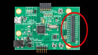
See also following picture of MC310 Jumpers configurations :
AVR172
3
8306B-AVR-05/10
Figure 1. MC310 Jumpers configuration
2.2 MC300 jumper settings
Table 2-1. ATAVRMC300 jumpers setting for sensorless control
Designator Setting Function
J2 none provide +5V to supply the ATAVRMC310 board
On ATAVRMC300, Vm and Vin connectors can be supplied from the same +12V/7A
power supply. Nevertheless a separate +12V/1A can also be used to supply the Vin
(processor supply voltage).
2.3 Power-supply
This firmware example has been configured according to a power-supply Vm=12V.
This power-supply must be able to provide up to 4A output current.
2.4 Motor
The BLDC motor provided inside MC320 and MC300 Motor Control Kit has the
following characteristics:
Manufacturer : TECMOTION
Number of phases : 3
Number of poles : 8 (4 pairs)
Rated voltage : 24V
Rated speed : 4000 rpm
Rated torque : 62.5 Nm
Torque constant : 35 Nm/A = k_tau
4 AVR172
8306B-AVR-05/10
Line to Line Resistance : 1.8 ohm = R
Back EMF : 3.66 V/Krpm = k_e
Peak current : 5.4A
As Vm=12V, the rated speed will be 2000 rpm.
2.5 ATmega32M1 Configuration
ATmega32M1 must be programmed to run at 16MHz using PLL (set corresponding
Fuse bits).
The CKDIV8 fuse must be disabled.
Extended/High/Low Fuses configurations are : FF/DF/F3
2.6 Technical Advices
2.6.1 Disconnecting the BLDC Motor
The BLDC motor must not be disconnected while it is running or while its coils carry
current. It is allowed to disconnect a BLDC motor if the PWM duty cycle is 0% and the
rotor is at rest so that no current is driven through the coils. Be careful, when stopping
the power supply or PWM, a BLDC motor with a high moment of inertia is able to run
for a relatively long time.
2.6.2 Ground and Power Wirings
One design its own board has to take care of the ground wiring and power wiring. The
power supply of the processor and additional signal conditioning components (e.g.
additional fast comparators, operational amplifiers, …) has to be decoupled from the
motor power supply. The ground connection has to be of low resistance and low
inductance to prevent against voltage drop and noise due to high currents. A ground
plane within a multi layer PCB is recommended for proper operation.
3 Firmware
The example firmware is based on the Sensorless method described in AVR928
Application Note.
It is operating in sensorless mode using the ATmega32M1 internal comparators. Hall
sensor wires of the BLDC motor of the kit can remain unconnected.
The source file directory embeds an html documentation which can be opened
through the readme.html file.
The theory of the different tasks has been detailed in AVR928. The application to
ATmega32M1 is detailed in following sections.
3.1 Main Flow chart
The firmware main flowchart is described below :
AVR172
5
8306B-AVR-05/10
Figure 2. Main flow chart
The tasks are scheduled thanks to the g_tick produced each 1.024ms with Timer0.
6 AVR172
8306B-AVR-05/10
3.2 MS_ALIGN phase
The ALIGN phase forces the motor at a specific position. The time of this phase is
controlled with ALIGN_TIME constant which is the ru_period_counter initial value
(200 for MC310 motor).
3.3 RAMP_UP phase
The ramp-up charateristics (duty-cycles and times) are stored in two tables:
• ramp_up_duty_table[] : which provides the duty_cycle of the step
• ramp_up_time_table[] : which provides the length of the step (ru_step_length)
These two tables are specific to the motor and the application.
The scanning of the step sequences and the monitoring of the step length are
achieved thanks to three independant counters :
- ru_step_length_cntr : which counts the commutation time (up to ru_step_length
variable)
- ru_period_counter : which counts the step length (up to RAMP_UP_PERIOD
constant)
- ramp_up_index : which counts the step numbers (up to
RAMP_UP_INDEX_MAX constant)
The figure below provides a waveform of steps timing :
Figure 3. Steps timing
AVR172
7
8306B-AVR-05/10
3.3.1 Time of steps
The step time is RAMP_UP_PERIOD = 50ms.
3.3.2 Number of steps
The parameter : RAMP_UP_INDEX_MAX = 9, defines 10 steps ramp up.
3.3.3 Parameters tables
In firmware example, the tables have been defined according to the characteristics of
the motor provided in the kit (see parameters in 2.4 Motor section) :
ramp_up_time_table[] = {26,23,20,17,14,11,8,5,3,2,2};
ramp_up_duty_table[] = {122,124,126,129,131,133,135,137,140,143,145};
3.3.4 Sp1/pwm1
The usual parameters described in AVR928 Application Note are:
• Pwm1 = 50%
• Sp1 = Sp_max/60
The parameters defined with MC310 Tecmotion motor are:
• Pwm1 = 48% (= 122/256)
• Sp1 :
Sp1 is defined thanks to the initialization value of ru_step_length :
ru_step_length = RAMP_UP_STEP_MAX = 40
This variable determines one commutation each 40ms.
So an electrical rotation time is 120ms. As the motor has 4 pairs of poles, the
mechanical rotation time is 480ms. So the rotation speed is 60/0.48 = 125 rpm.
So Sp1 = Sp_max/32.
The second value of ru_step_length is 26 in the time table. It defines the following
commutation time.
3.3.5 Sp2/pwm2
The theorical parameters described in AVR928 Application Note are:
• Pwm2 = 60%
• Sp2 = Sp_max/6 = Sp1 / 10
The parameters defined with Tecmotion motor are:
• Pwm2 = 57% (= 145/256)
• Sp2 :
Sp2 is defined thanks to the last value of ru_step_length : 2
This variable determines one commutation each 4ms.
So an electrical rotation time is 12ms. As the motor has 4 pairs of poles, the
mechanical rotation time is 48ms. So the rotation speed is 60/0.048 = 1250 rpm.
So Sp2 = Sp_max/3.2.
8 AVR172
8306B-AVR-05/10
This confirms also the usual ratio = 10 between Sp1 and Sp2 which is defined in
AVR498 Application Note.
3.4 LAST_RAMP_UP phase
To avoid a shorten last step, this phase monitors the last ramp-up step to guarantee it
is ended properly before running in closed loop.
3.5 RUNNING Phase
3.5.1 Closed-loop block diagram
The Running phase is a sensorless closed loop which block diagram is following :
Figure 4. Closed-loop block diagram
AVR172
9
8306B-AVR-05/10
3.5.2 Running flowchart
The flowchart is following :
Figure 5. Closed-loop flowchart
•
Motor_state is kept equal to MS_RUNNING
mci_set_ref_speed() function updates the speed setpoint according to the
potentiometer adjustment or the speed command received on serial transmission.
In mc_regulation_loop() function, duty_cycle_reference is the duty_cycle variable
which controls the PWM generator. This variable is the result of following functions :
• In OPEN_LOOP:
mci_set_ref_speed() function
• In SPEED_LOOP:
10 AVR172
8306B-AVR-05/10
mc_control_speed(2*mci_get_ref_speed())
duty-cycle_reference is calculated from ref_speed and from
monitored mci_get_measured_speed()
measured_speed = (KSPEED * 4) / mci_measured_period
with mci_measured_period calculated in the Interrupt vector of
Analog Comparator 1. This interrupt uses Timer 0 to compute the
period.
• In CURRENT_LOOP :
mc_control_current(mc_get_potentiometer_value()
3.5.3 Sensorless Detection and Commutation Management
The analog comparators 0, 1 and 2 are used to detect the zero crossing of the U, V
and W phases.
The timer 1 is used to monitor the time between two consecutive zero crossings. This
time corresponds to one sector of the electrical rotation of the motor. It equals 60° of
the entire electrical period of the motor.
When a zero crossing event occurs, the timer 1 value is stored. Then this value is
divided by 2 (providing the 30° time) and loaded into the Compare A register of timer
1. Then this value is added to the half of itself to provide the 45° time and loaded into
the Compare B register of timer 1.
The timer 1 compare A event occurs 30° after the zero crossing. It activates the next
commutation state and masks the zero crossing to avoid the discharge of the
inductance (demagnetization) pulse generated at the end of a step when the active
switches are released.
Due to the inductance of the motor coils, a voltage equals to -Ldi/dt is generated, the
demagnetization is done through the diodes of the power bridge.
The timer 1 compare B event releases the zero crossing mask : enables the
comparator n interrupt according to the motor_step variable. This Timer1 interrupt
provides the demagnetization mask delay.
AVR172
11
8306B-AVR-05/10
4 RS232 Communication with firmware
4.1 Connecting ATAVRMC310 to use the RS232 interface
Connect PC com port to the ATAVRMC310 RS232 connector through a direct cable.
The serial configuration is:
• 38400 bauds,
• 8 bit data bit,
• 1 stop bit,
• no handshake,
4.2 PC applications
User can communicate with firmware through RS232 with usual PC serial
communication applications (i.e. Hyperterminal) or the Atmel “Motor Control Center”
application which can be downloaded from Atmel web at url : http://www.atmel.com
4.2.1 PC Terminal : RS232 Messages and Commands
At power up the following welcome message is received on terminal :
“ATMEL Motor Control Interface”.
The following commands can be sent to the firmware:
Table 2-1. List of commands
Command Action
ru Run motor
st Stop Motor
help Gives help
fw Set direction to Forward
bw Set direction to Backward
ss Set Speed (followed with speed value)
gi Get ID
g0 Get Status 0
g1 Get Status 1
4.2.2 Motor Control Center
The User Guide is available in Install directory at URL :
C:\Program Files\Atmel\Motor Control Center\help\Overview.htm
The AVR172 Target must be selected first to get the right configuration :
To select a target, execute the File > Select Target command or click the
button in the toolbar. The following dialog pops up:
12 AVR172
8306B-AVR-05/10
Figure 6. Motor Control Center Interface
5 USB communication
Communication can be achieved from PC to USB connector of MC310 board.
The AVR470, MC310 Hardware User Guide details the configuration to be achieved.
Communication port becomes a Virtual Com port. Same tools as described in section
4 (RS232 Communication with firmware), can be used through this Virtual Com port.
8306B-AVR-05/10
Disclaimer
Headquarters International
Atmel Corporation
2325 Orchard Parkway
San Jose, CA 95131
USA
Tel: 1(408) 441-0311
Fax: 1(408) 487-2600
Atmel Asia
Unit 1-5 & 16, 19/F
BEA Tower, Millennium City 5
418 Kwun Tong Road
Kwun Tong, Kowloon
Hong Kong
Tel: (852) 2245-6100
Fax: (852) 2722-1369
Product Contact
Atmel Europe
Le Krebs
8, Rue Jean-Pierre Timbaud
BP 309
78054 Saint-Quentin-en-
Yvelines Cedex
France
Tel: (33) 1-30-60-70-00
Fax: (33) 1-30-60-71-11
Atmel Japan
9F, Tonetsu Shinkawa Bldg.
1-24-8 Shinkawa
Chuo-ku, Tokyo 104-0033
Japan
Tel: (81) 3-3523-3551
Fax: (81) 3-3523-7581
Web Site
http://www.atmel.com/
Technical Support
avr@atmel.com
Sales Contact
www.atmel.com/contacts
Literature Request
www.atmel.com/literature
Disclaimer: The information in this document is provided in connection with Atmel products. No license, express or implied, by estoppel or otherwise, to any
intellectual property right is granted by this document or in connection with the sale of Atmel products. EXCEPT AS SET FORTH IN ATMEL’S TERMS AND
CONDITIONS OF SALE LOCATED ON ATMEL’S WEB SITE, ATMEL ASSUMES NO LIABILITY WHATSOEVER AND DISCLAIMS ANY EXPRESS, IMPLIED
OR STATUTORY WARRANTY RELATING TO ITS PRODUCTS INCLUDING, BUT NOT LIMITED TO, THE IMPLIED WARRANTY OF MERCHANTABILITY,
FITNESS FOR A PARTICULAR PURPOSE, OR NON-INFRINGEMENT. IN NO EVENT SHALL ATMEL BE LIABLE FOR ANY DIRECT, INDIRECT,
CONSEQUENTIAL, PUNITIVE, SPECIAL OR INCIDENTAL DAMAGES (INCLUDING, WITHOUT LIMITATION, DAMAGES FOR LOSS OF PROFITS,
BUSINESS INTERRUPTION, OR LOSS OF INFORMATION) ARISING OUT OF THE USE OR INABILITY TO USE THIS DOCUMENT, EVEN IF ATMEL HAS
BEEN ADVISED OF THE POSSIBILITY OF SUCH DAMAGES. Atmel makes no representations or warranties with respect to the accuracy or completeness of the
contents of this document and reserves the right to make changes to specifications and product descriptions at any time without notice. Atmel does not make any
commitment to update the information contained herein. Unless specifically provided otherwise, Atmel products are not suitable for, and shall not be used in,
automotive applications. Atmel’s products are not intended, authorized, or warranted for use as components in applications intended to support or sustain life.
© 2010 Atmel Corporation. All rights reserved. Atmel®, Atmel logo and combinations thereof, AVR®, AVR® logo and others, are the
registered trademarks or trademarks of Atmel Corporation or its subsidiaries. Other terms and product names may be trademarks of others.
http://www.farnell.com/datasheets/1734386.pdf
1. Product profile
1.1 General description
NPN/NPN general-purpose transistor pair in a small SOT457 (SC-74) Surface-Mounted
Device (SMD) plastic package.
1.2 Features
■ Low collector capacitance
■ Low collector-emitter saturation voltage
■ Closely matched current gain
■ Reduces number of components and board space
■ No mutual interference between the transistors
■ AEC-Q101 qualified
1.3 Applications
■ General-purpose switching and amplification
1.4 Quick reference data
BC847DS
45 V, 100 mA NPN/NPN general-purpose transistor
Rev. 01 — 25 August 2009 Product data sheet
Table 1. Quick reference data
Symbol Parameter Conditions Min Typ Max Unit
Per transistor
VCEO collector-emitter voltage open base - - 45 V
IC collector current - - 100 mA
hFE DC current gain VCE = 5 V; IC = 2 mA 200 300 450BC847DS_1 © NXP B.V. 2009. All rights reserved.
Product data sheet Rev. 01 — 25 August 2009 2 of 12
NXP Semiconductors BC847DS
45 V, 100 mA NPN/NPN general-purpose transistor
2. Pinning information
3. Ordering information
4. Marking
5. Limiting values
Table 2. Pinning
Pin Description Simplified outline Graphic symbol
1 emitter TR1
2 base TR1
3 collector TR2
4 emitter TR2
5 base TR2
6 collector TR1
1 3 2
6 5 4
sym020
1 2 3
6 5
TR1
TR2
4
Table 3. Ordering information
Type number Package
Name Description Version
BC847DS SC-74 plastic surface-mounted package (TSOP6); 6 leads SOT457
Table 4. Marking codes
Type number Marking code
BC847DS ZL
Table 5. Limiting values
In accordance with the Absolute Maximum Rating System (IEC 60134).
Symbol Parameter Conditions Min Max Unit
Per transistor
VCBO collector-base voltage open emitter - 50 V
VCEO collector-emitter voltage open base - 45 V
VEBO emitter-base voltage open collector - 6 V
IC collector current - 100 mA
ICM peak collector current single pulse;
tp ≤ 1 ms
- 200 mA
IBM peak base current single pulse;
tp ≤ 1 ms
- 200 mA
Ptot total power dissipation Tamb ≤ 25 °C [1] - 250 mW
Per device
Ptot total power dissipation Tamb ≤ 25 °C [1] - 380 mWBC847DS_1 © NXP B.V. 2009. All rights reserved.
Product data sheet Rev. 01 — 25 August 2009 3 of 12
NXP Semiconductors BC847DS
45 V, 100 mA NPN/NPN general-purpose transistor
[1] Device mounted on an FR4 Printed-Circuit Board (PCB), single-sided copper, tin-plated and standard
footprint.
6. Thermal characteristics
[1] Device mounted on an FR4 PCB, single-sided copper, tin-plated and standard footprint.
Tj junction temperature - 150 °C
Tamb ambient temperature −55 +150 °C
Tstg storage temperature −65 +150 °C
FR4 PCB, standard footprint
Fig 1. Per device: Power derating curve SOT457 (SC-74)
Table 5. Limiting values …continued
In accordance with the Absolute Maximum Rating System (IEC 60134).
Symbol Parameter Conditions Min Max Unit
Tamb (°C)
−75 175 −25 25 75 125
006aab621
200
300
100
400
500
Ptot
(mW)
0
Table 6. Thermal characteristics
Symbol Parameter Conditions Min Typ Max Unit
Per transistor
Rth(j-a) thermal resistance from
junction to ambient
in free air [1] - - 500 K/W
Rth(j-sp) thermal resistance from
junction to solder point
- - 250 K/W
Per device
Rth(j-a) thermal resistance from
junction to ambient
in free air [1] - - 328 K/WBC847DS_1 © NXP B.V. 2009. All rights reserved.
Product data sheet Rev. 01 — 25 August 2009 4 of 12
NXP Semiconductors BC847DS
45 V, 100 mA NPN/NPN general-purpose transistor
7. Characteristics
FR4 PCB, standard footprint
Fig 2. Per transistor: Transient thermal impedance from junction to ambient as a function of pulse duration;
typical values
006aab622
10−5 10 10 −2 10−4 102 10−1
tp (s)
10−3 103 1
102
10
103
Zth(j-a)
(K/W)
1
δ = 1
0.75
0.50
0.33
0.10
0.05
0.02
0.01
0
0.20
Table 7. Characteristics
Tamb = 25 °C unless otherwise specified.
Symbol Parameter Conditions Min Typ Max Unit
Per transistor
ICBO collector-base cut-off
current
VCB = 30 V; IE = 0 A - - 15 nA
VCB = 30 V; IE = 0 A;
Tj = 150 °C
--5 µA
IEBO emitter-base cut-off
current
VEB = 6 V; IC = 0 A - - 100 nA
hFE DC current gain VCE =5V
IC = 10 µA - 280 -
IC = 2 mA 200 300 450
VCEsat collector-emitter
saturation voltage
IC = 10 mA; IB = 0.5 mA - 55 100 mV
IC = 100 mA; IB = 5 mA - 200 300 mV
VBEsat base-emitter
saturation voltage
IC = 10 mA; IB = 0.5 mA - 755 850 mV
IC = 100 mA; IB = 5 mA - 1000 - mV
VBE base-emitter voltage VCE =5V
IC = 2 mA 580 650 700 mV
IC = 10 mA - - 770 mVBC847DS_1 © NXP B.V. 2009. All rights reserved.
Product data sheet Rev. 01 — 25 August 2009 5 of 12
NXP Semiconductors BC847DS
45 V, 100 mA NPN/NPN general-purpose transistor
Cc collector capacitance VCB = 10 V; IE = ie = 0 A;
f = 1 MHz
- 1.9 - pF
Ce emitter capacitance VEB = 0.5 V; IC = ic = 0 A;
f = 1 MHz
- 11 - pF
fT transition frequency VCE = 5 V; IC = 10 mA;
f = 100 MHz
100 - - MHz
NF noise figure VCE = 5 V; IC = 0.2 mA;
RS =2kΩ;
f = 10 Hz to 15.7 kHz
- 1.9 - dB
VCE = 5 V; IC = 0.2 mA;
RS =2kΩ; f = 1 kHz;
B = 200 Hz
- 3.1 - dB
Table 7. Characteristics …continued
Tamb = 25 °C unless otherwise specified.
Symbol Parameter Conditions Min Typ Max Unit
VCE =5V
(1) Tamb = 100 °C
(2) Tamb = 25 °C
(3) Tamb = −55 °C
Tamb = 25 °C
Fig 3. Per transistor: DC current gain as a function of
collector current; typical values
Fig 4. Per transistor: Collector current as a function
of collector-emitter voltage; typical values
006aaa533
200
400
600
hFE
0
IC (mA)
10−2 103 102 10−1 1 10
(3)
(1)
(2)
006aaa532
VCE (V)
0 10 2 4 6 8
0.08
0.12
0.04
0.16
0.20
IC
(A)
0
IB (mA) = 4.50
2.70
3.15
4.05
3.60
0.45
0.90
1.35
1.80
2.25BC847DS_1 © NXP B.V. 2009. All rights reserved.
Product data sheet Rev. 01 — 25 August 2009 6 of 12
NXP Semiconductors BC847DS
45 V, 100 mA NPN/NPN general-purpose transistor
VCE = 5 V; Tamb = 25 °C IC/IB = 20
(1) Tamb = −55 °C
(2) Tamb = 25 °C
(3) Tamb = 100 °C
Fig 5. Per transistor: Base-emitter voltage as a
function of collector current; typical values
Fig 6. Per transistor: Base-emitter saturation voltage
as a function of collector current;
typical values
IC/IB = 20
(1) Tamb = 100 °C
(2) Tamb = 25 °C
(3) Tamb = −55 °C
VCE = 5 V; Tamb = 25 °C
Fig 7. Per transistor: Collector-emitter saturation
voltage as a function of collector current;
typical values
Fig 8. Per transistor: Transition frequency as a
function of collector current; typical values
006aaa536
0.6
0.8
1
VBE
(V)
0.4
IC (mA)
10−1 103 102 1 10
006aaa534
IC (mA)
10−1 103 102 1 10
0.5
0.9
1.3
0.3
0.7
1.1
VBEsat
(V)
0.1
(1)
(2)
(3)
006aaa535
1
10−1
10
VCEsat
(V)
10−2
IC (mA)
10−1 103 102 1 10
(1)
(2)
(3)
006aaa537
IC (mA)
1 102 10
102
103
fT
(MHz)
10BC847DS_1 © NXP B.V. 2009. All rights reserved.
Product data sheet Rev. 01 — 25 August 2009 7 of 12
NXP Semiconductors BC847DS
45 V, 100 mA NPN/NPN general-purpose transistor
f = 1 MHz; Tamb = 25 °C f = 1 MHz; Tamb = 25 °C
Fig 9. Per transistor: Collector capacitance as a
function of collector-base voltage;
typical values
Fig 10. Per transistor: Emitter capacitance as a
function of emitter-base voltage; typical values
VCB (V)
0 10 2 4 6 8
006aab620
2
4
6
Cc
(pF)
0
006aaa539
VEB (V)
0 6 2 4
9
11
7
13
15
Ce
(pF)
5BC847DS_1 © NXP B.V. 2009. All rights reserved.
Product data sheet Rev. 01 — 25 August 2009 8 of 12
NXP Semiconductors BC847DS
45 V, 100 mA NPN/NPN general-purpose transistor
8. Test information
8.1 Quality information
This product has been qualified in accordance with the Automotive Electronics Council
(AEC) standard Q101 - Stress test qualification for discrete semiconductors, and is
suitable for use in automotive applications.
9. Package outline
10. Packing information
[1] For further information and the availability of packing methods, see Section 14.
[2] T1: normal taping
[3] T2: reverse taping
Fig 11. Package outline SOT457 (SC-74)
Dimensions in mm 04-11-08
3.0
2.5
1.7
1.3
3.1
2.7
pin 1 index
1.9
0.26
0.10
0.40
0.25 0.95
1.1
0.9
0.6
0.2
1 3 2
6 5 4
Table 8. Packing methods
The indicated -xxx are the last three digits of the 12NC ordering code.[1]
Type number Package Description Packing quantity
3000 10000
BC847DS SOT457 4 mm pitch, 8 mm tape and reel; T1 [2] -115 -135
4 mm pitch, 8 mm tape and reel; T2 [3] -125 -165BC847DS_1 © NXP B.V. 2009. All rights reserved.
Product data sheet Rev. 01 — 25 August 2009 9 of 12
NXP Semiconductors BC847DS
45 V, 100 mA NPN/NPN general-purpose transistor
11. Soldering
Fig 12. Reflow soldering footprint SOT457 (SC-74)
Fig 13. Wave soldering footprint SOT457 (SC-74)
solder lands
solder resist
occupied area
solder paste
sot457_fr
3.45
1.95
3.3 2.825
0.45
(6×)
0.55
(6×)
0.7
(6×)
0.8
(6×)
2.4
0.95
0.95
Dimensions in mm
sot457_fw
5.3
5.05
1.45
(6×)
0.45
(2×)
1.5
(4×)
2.85
1.475
1.475
solder lands
solder resist
occupied area
preferred transport
direction during soldering
Dimensions in mmBC847DS_1 © NXP B.V. 2009. All rights reserved.
Product data sheet Rev. 01 — 25 August 2009 10 of 12
NXP Semiconductors BC847DS
45 V, 100 mA NPN/NPN general-purpose transistor
12. Revision history
Table 9. Revision history
Document ID Release date Data sheet status Change notice Supersedes
BC847DS_1 20090825 Product data sheet - -BC847DS_1 © NXP B.V. 2009. All rights reserved.
Product data sheet Rev. 01 — 25 August 2009 11 of 12
NXP Semiconductors BC847DS
45 V, 100 mA NPN/NPN general-purpose transistor
13. Legal information
13.1 Data sheet status
[1] Please consult the most recently issued document before initiating or completing a design.
[2] The term ‘short data sheet’ is explained in section “Definitions”.
[3] The product status of device(s) described in this document may have changed since this document was published and may differ in case of multiple devices. The latest product status
information is available on the Internet at URL http://www.nxp.com.
13.2 Definitions
Draft — The document is a draft version only. The content is still under
internal review and subject to formal approval, which may result in
modifications or additions. NXP Semiconductors does not give any
representations or warranties as to the accuracy or completeness of
information included herein and shall have no liability for the consequences of
use of such information.
Short data sheet — A short data sheet is an extract from a full data sheet
with the same product type number(s) and title. A short data sheet is intended
for quick reference only and should not be relied upon to contain detailed and
full information. For detailed and full information see the relevant full data
sheet, which is available on request via the local NXP Semiconductors sales
office. In case of any inconsistency or conflict with the short data sheet, the
full data sheet shall prevail.
13.3 Disclaimers
General — Information in this document is believed to be accurate and
reliable. However, NXP Semiconductors does not give any representations or
warranties, expressed or implied, as to the accuracy or completeness of such
information and shall have no liability for the consequences of use of such
information.
Right to make changes — NXP Semiconductors reserves the right to make
changes to information published in this document, including without
limitation specifications and product descriptions, at any time and without
notice. This document supersedes and replaces all information supplied prior
to the publication hereof.
Suitability for use — NXP Semiconductors products are not designed,
authorized or warranted to be suitable for use in medical, military, aircraft,
space or life support equipment, nor in applications where failure or
malfunction of an NXP Semiconductors product can reasonably be expected
to result in personal injury, death or severe property or environmental
damage. NXP Semiconductors accepts no liability for inclusion and/or use of
NXP Semiconductors products in such equipment or applications and
therefore such inclusion and/or use is at the customer’s own risk.
Applications — Applications that are described herein for any of these
products are for illustrative purposes only. NXP Semiconductors makes no
representation or warranty that such applications will be suitable for the
specified use without further testing or modification.
Limiting values — Stress above one or more limiting values (as defined in
the Absolute Maximum Ratings System of IEC 60134) may cause permanent
damage to the device. Limiting values are stress ratings only and operation of
the device at these or any other conditions above those given in the
Characteristics sections of this document is not implied. Exposure to limiting
values for extended periods may affect device reliability.
Terms and conditions of sale — NXP Semiconductors products are sold
subject to the general terms and conditions of commercial sale, as published
at http://www.nxp.com/profile/terms, including those pertaining to warranty,
intellectual property rights infringement and limitation of liability, unless
explicitly otherwise agreed to in writing by NXP Semiconductors. In case of
any inconsistency or conflict between information in this document and such
terms and conditions, the latter will prevail.
No offer to sell or license — Nothing in this document may be interpreted
or construed as an offer to sell products that is open for acceptance or the
grant, conveyance or implication of any license under any copyrights, patents
or other industrial or intellectual property rights.
Export control — This document as well as the item(s) described herein
may be subject to export control regulations. Export might require a prior
authorization from national authorities.
Quick reference data — The Quick reference data is an extract of the
product data given in the Limiting values and Characteristics sections of this
document, and as such is not complete, exhaustive or legally binding.
13.4 Trademarks
Notice: All referenced brands, product names, service names and trademarks
are the property of their respective owners.
14. Contact information
For more information, please visit: http://www.nxp.com
For sales office addresses, please send an email to: salesaddresses@nxp.com
Document status[1][2] Product status[3] Definition
Objective [short] data sheet Development This document contains data from the objective specification for product development.
Preliminary [short] data sheet Qualification This document contains data from the preliminary specification.
Product [short] data sheet Production This document contains the product specification.NXP Semiconductors BC847DS
45 V, 100 mA NPN/NPN general-purpose transistor
© NXP B.V. 2009. All rights reserved.
For more information, please visit: http://www.nxp.com
For sales office addresses, please send an email to: salesaddresses@nxp.com
Date of release: 25 August 2009
Document identifier: BC847DS_1
Please be aware that important notices concerning this document and the product(s)
described herein, have been included in section ‘Legal information’.
15. Contents
1 Product profile . . . . . . . . . . . . . . . . . . . . . . . . . . 1
1.1 General description. . . . . . . . . . . . . . . . . . . . . . 1
1.2 Features . . . . . . . . . . . . . . . . . . . . . . . . . . . . . . 1
1.3 Applications . . . . . . . . . . . . . . . . . . . . . . . . . . . 1
1.4 Quick reference data. . . . . . . . . . . . . . . . . . . . . 1
2 Pinning information . . . . . . . . . . . . . . . . . . . . . . 2
3 Ordering information . . . . . . . . . . . . . . . . . . . . . 2
4 Marking . . . . . . . . . . . . . . . . . . . . . . . . . . . . . . . . 2
5 Limiting values. . . . . . . . . . . . . . . . . . . . . . . . . . 2
6 Thermal characteristics. . . . . . . . . . . . . . . . . . . 3
7 Characteristics. . . . . . . . . . . . . . . . . . . . . . . . . . 4
8 Test information . . . . . . . . . . . . . . . . . . . . . . . . . 8
8.1 Quality information . . . . . . . . . . . . . . . . . . . . . . 8
9 Package outline . . . . . . . . . . . . . . . . . . . . . . . . . 8
10 Packing information. . . . . . . . . . . . . . . . . . . . . . 8
11 Soldering . . . . . . . . . . . . . . . . . . . . . . . . . . . . . . 9
12 Revision history. . . . . . . . . . . . . . . . . . . . . . . . 10
13 Legal information. . . . . . . . . . . . . . . . . . . . . . . 11
13.1 Data sheet status . . . . . . . . . . . . . . . . . . . . . . 11
13.2 Definitions. . . . . . . . . . . . . . . . . . . . . . . . . . . . 11
13.3 Disclaimers . . . . . . . . . . . . . . . . . . . . . . . . . . . 11
13.4 Trademarks. . . . . . . . . . . . . . . . . . . . . . . . . . . 11
14 Contact information. . . . . . . . . . . . . . . . . . . . . 11
15 Contents . . . . . . . . . . . . . . . . . . . . . . . . . . . . . . 12
http://www.farnell.com/datasheets/480916.pdf
Plug and Play Wireless CPU®
Fastrack Supreme
User Guide
Revision: 003
Date: November 2007
© Restricted Page: 1 / 82
This document is the sole and exclusive property of Wavecom. Not to be distributed or divulged
without prior written agreement.
WA_DEV_Fastrk_UGD_001-003 November 5, 2007
Plug and Play Wireless CPU®
Fastrack Supreme
User Guide
Reference: WA_DEV_Fastrk_UGD_001
Revision: 003
Date: November 5, 2007
Supports Open AT® embedded ANSI C applications
Fastrack Supreme User Guide
© Restricted Page: 2 / 82
This document is the sole and exclusive property of Wavecom. Not to be distributed or divulged
without prior written agreement.
WA_DEV_Fastrk_UGD_001-003 November 5, 2007
Document History
Revision Date List of revisions
001 June 5, 2007 First Issue
002 September 6, 2007 Update
003 November 5, 2007 Update
Fastrack Supreme User Guide
© Restricted Page: 3 / 82
This document is the sole and exclusive property of Wavecom. Not to be distributed or divulged
without prior written agreement.
WA_DEV_Fastrk_UGD_001-003 November 5, 2007
Overview
The Fastrack Supreme 10 and Fastrack Supreme 20 are discrete, rugged cellular Plug
& Play Wireless CPU® offering state-of-the-art GSM/GPRS (and EGPRS for Fastrack
Supreme 20) connectivity for machine to machine applications.
Proven for reliable, stable performance on wireless networks worldwide, Wavecom’s
latest generation of Fastrack Supreme continues to deliver rapid time to market and
painless integration.
Having comparable size with the previous M1306B generation, and updated with
new features, the Fastrack Supreme offers an Internal Expansion Socket (IES)
interface accessible for customer use. Expanding application features is easy without
voiding the warrantee of the Fastrack Supreme by simply plugging in of an Internal
Expansion Socket Module (IESM) board.
Fully certified, the quad band 850/900/1800/1900 MHz Fastrack Supreme 10 offers
GPRS Class 10 capability and Fastrack Supreme 20 offers GPRS/EGPRS Class 10
capability. Both support a powerful open software platform (Open AT®). Open AT® is
the world’s most comprehensive cellular development environment, which allows
embedded standard ANSI C applications to be natively executed directly on the
Wireless CPU®.
Fastrack Supreme is controlled by firmware through a set of AT commands.
This document describes the Fastrack Supreme and gives information on the
following topics:
• general presentation,
• functional description,
• basic services available,
• technical characteristics,
• installing and using the Fastrack Supreme,
• user-level troubleshooting.
• recommended accessories to be used with the product.
Note:
This document covers the Fastrack Supreme Plug & Play alone and does not include
The programmable capabilities provided via the use of Open AT® Software
Suites.
The development guide for IESM for expanding the application feature through
the IES interface.
For detailed, please refer to the documents shown in the "Reference Documents"
section.
Fastrack Supreme User Guide
© Restricted Page: 4 / 82
This document is the sole and exclusive property of Wavecom. Not to be distributed or divulged
without prior written agreement.
WA_DEV_Fastrk_UGD_001-003 November 5, 2007
RoHS Directive
The Fastrack Supreme is now compliant with RoHS Directive 2002/95/EC, which sets
limits for the use of certain restricted hazardous substances. This directive states that
"from 1st July 2006, new electrical and electronic equipment put on the market does
not contain lead, mercury, cadmium, hexavalent chromium, polybrominated
biphenyls (PBB), and polybrominated diphenyl ethers (PBDE)".
Plug & Plays which are compliant with this directive are
identified by the RoHS logo on their label.
Disposing of the product
This electronic product is subject to the EU Directive
2002/96/EC for Waste Electrical and Electronic Equipment
(WEEE). As such, this product must not be disposed off at a
municipal waste collection point. Please refer to local
regulations for directions on how to dispose off this product
in an environmental friendly manner.
Fastrack Supreme User Guide
© Restricted Page: 5 / 82
This document is the sole and exclusive property of Wavecom. Not to be distributed or divulged
without prior written agreement.
WA_DEV_Fastrk_UGD_001-003 November 5, 2007
Cautions
Information furnished herein by WAVECOM is accurate and reliable. However, no
responsibility is assumed for its use. Please read carefully the safety
recommendations given in Section 9 for an application based on Fastrack Supreme
Plug & Play.
Trademarks
®, WAVECOM®, Wireless CPU®, Open AT® and certain other trademarks and logos
appearing on this document, are filed or registered trademarks of Wavecom S.A. in
France or in other countries. All other company and/or product names mentioned may
be filed or registered trademarks of their respective owners.
Copyright
This manual is copyrighted by WAVECOM with all rights reserved. No part of this
manual may be reproduced in any form without the prior written permission of
WAVECOM. No patent liability is assumed with respect to the use of their respective
owners.
Fastrack Supreme User Guide
© Restricted Page: 6 / 82
This document is the sole and exclusive property of Wavecom. Not to be distributed or divulged
without prior written agreement.
WA_DEV_Fastrk_UGD_001-003 November 5, 2007
Web Site Support
General information about Wavecom and its
range of products:
www.wavecom.com
Specific support is available for the Fastrack
Supreme Plug & Play Wireless CPU®:
www.wavecom.com/fastracksupreme
Open AT® Introduction: www.wavecom.com/OpenAT
Developer community for software and
hardware:
www.wavecom.com/forum
Fastrack Supreme User Guide
© Restricted Page: 7 / 82
This document is the sole and exclusive property of Wavecom. Not to be distributed or divulged
without prior written agreement.
WA_DEV_Fastrk_UGD_001-003 November 5, 2007
Contents
DOCUMENT HISTORY ...............................................................................................2
OVERVIEW................................................................................................................3
CAUTIONS ................................................................................................................5
TRADEMARKS ..........................................................................................................5
COPYRIGHT ..............................................................................................................5
WEB SITE SUPPORT .................................................................................................6
CONTENTS ...............................................................................................................7
LIST OF FIGURES ....................................................................................................11
LIST OF TABLES......................................................................................................12
1 REFERENCES.....................................................................................................14
1.1 Reference Documents..................................................................................... 14
1.1.1 Open AT® Software Documentation ........................................................ 14
1.1.2 AT Software Documentation................................................................... 14
1.1.3 Delta between M1306B Documents ....................................................... 14
1.1.4 IESM Related Documents ....................................................................... 14
1.2 Abbreviations ................................................................................................. 15
2 PACKAGING ......................................................................................................18
2.1 Contents......................................................................................................... 18
2.2 Packaging Box................................................................................................ 19
2.3 Production Labelling ....................................................................................... 20
3 GENERAL PRESENTATION.................................................................................21
3.1 Description ..................................................................................................... 21
3.2 External Connections...................................................................................... 23
3.2.1 Connectors ............................................................................................. 23
3.2.1.1 Antenna Connector ........................................................................... 23
3.2.1.2 Power Supply Connector................................................................... 23
Fastrack Supreme User Guide
© Restricted Page: 8 / 82
This document is the sole and exclusive property of Wavecom. Not to be distributed or divulged
without prior written agreement.
WA_DEV_Fastrk_UGD_001-003 November 5, 2007
3.2.1.3 Sub HD 15-pin Connector ................................................................. 24
3.2.1.4 IES Connector ................................................................................... 26
3.2.2 Power Supply Cable................................................................................ 30
4 FEATURES AND SERVICES................................................................................31
4.1 Basic Features and Services ........................................................................... 31
4.2 Additional NEW Features................................................................................ 33
4.2.1 Support Additional GSM850/PCS1900 Bands......................................... 33
4.2.2 IES Interface for Easy Expansion of Application Features ........................ 33
4.2.3 Serial Port Auto Shut Down or Improving Power Consumption .............. 33
4.2.4 Real Time Clock (RTC) for Saving Date and Time .................................... 34
4.2.5 SIM Card Lock Feature............................................................................ 34
5 USING THE FASTRACK SUPREME PLUG & PLAY...............................................35
5.1 Getting Started ............................................................................................... 35
5.1.1 Mount the Fastrack Supreme.................................................................. 35
5.1.2 Insert/extract the SIM card to/from the Fastrack Supreme....................... 35
5.1.3 Set up the Fastrack Supreme .................................................................. 37
5.1.4 Check the communication with the Fastrack Supreme............................ 38
5.1.5 Reset the Fastrack Supreme.................................................................... 39
5.2 Specific Recommendations when Using the Fastrack Supreme on Trucks...... 39
5.2.1 Recommended Power Supply Connection on Trucks .............................. 39
5.2.2 Technical Constraints on Trucks ............................................................. 40
5.3 Fastrack Supreme Operational Status............................................................. 41
5.4 Echo Function Disabled .................................................................................. 42
5.5 Verify the Received Signal Strength ................................................................ 43
5.6 Check the Pin Code Status.............................................................................. 43
5.7 Switch between EU/US Band(s) ...................................................................... 44
5.8 Check the Band(s) Selection ........................................................................... 44
5.9 Verify the Fastrack Supreme Network Registration ......................................... 45
5.10 Main AT Commands for the Plug & Play ........................................................ 46
5.11 Firmware Upgrade Procedure ......................................................................... 48
6 TROUBLESHOOTING.........................................................................................49
6.1 No Communication with the Fastrack Supreme through the Serial Link.......... 49
6.2 Receiving "ERROR" Message ........................................................................... 50
6.3 Receiving "NO CARRIER" Message .................................................................. 50
7 FUNCTIONAL DESCRIPTION..............................................................................53
7.1 Architecture.................................................................................................... 53
Fastrack Supreme User Guide
© Restricted Page: 9 / 82
This document is the sole and exclusive property of Wavecom. Not to be distributed or divulged
without prior written agreement.
WA_DEV_Fastrk_UGD_001-003 November 5, 2007
7.2 EU and US Bands ........................................................................................... 54
7.2.1 General Presentation............................................................................... 54
7.2.2 AT COMMAND for Bands Switch ........................................................... 54
7.3 Power Supply ................................................................................................. 54
7.3.1 General Presentation............................................................................... 54
7.3.2 Protections.............................................................................................. 54
7.4 RS232 Serial Link............................................................................................ 55
7.4.1 General Presentation............................................................................... 55
7.4.2 Autobauding Mode................................................................................. 56
7.4.3 Pin Description........................................................................................ 56
7.4.4 Serial Port Auto shut down Feature ........................................................ 56
7.5 General Purpose Input/Output (GPIO) ............................................................. 57
7.6 BOOT ............................................................................................................. 57
7.7 RESET ............................................................................................................ 58
7.7.1 General Presentation............................................................................... 58
7.7.2 Reset Sequence ...................................................................................... 58
7.8 Audio.............................................................................................................. 59
7.8.1 Microphone Inputs.................................................................................. 59
7.8.2 Speaker Outputs ..................................................................................... 60
7.9 Real Time Clock (RTC)..................................................................................... 60
7.10 FLASH LED 61
8 TECHNICAL CHARACTERISTICS ........................................................................62
8.1 Mechanical Characteristics ............................................................................. 62
8.2 Electrical Characteristics ................................................................................. 64
8.2.1 Power Supply ......................................................................................... 64
8.2.2 Power Consumption ............................................................................... 65
8.2.3 Audio Interface ....................................................................................... 68
8.2.4 General Purpose Input/Output................................................................. 69
8.2.5 SIM Interface .......................................................................................... 69
8.2.6 RESET Signal .......................................................................................... 69
8.2.7 RF Characteristics ................................................................................... 70
8.2.7.1 Frequency Ranges ............................................................................ 70
8.2.7.2 RF Performances............................................................................... 71
8.2.7.3 External Antenna .............................................................................. 71
8.3 Environmental Characteristics ........................................................................ 72
8.4 Conformity...................................................................................................... 75
8.5 Protections ..................................................................................................... 75
8.5.1 Power Supply ......................................................................................... 75
8.5.2 Overvoltage............................................................................................. 76
8.5.3 Electrostatic Discharge............................................................................ 76
8.5.4 Miscellaneous......................................................................................... 76
9 SAFETY RECOMMENDATIONS..........................................................................77
Fastrack Supreme User Guide
© Restricted Page: 10 / 82
This document is the sole and exclusive property of Wavecom. Not to be distributed or divulged
without prior written agreement.
WA_DEV_Fastrk_UGD_001-003 November 5, 2007
9.1 General Safety ................................................................................................ 77
9.2 Vehicle Safety ................................................................................................. 78
9.3 Care and Maintenance.................................................................................... 78
9.4 Your Responsibility ......................................................................................... 79
10 RECOMMENDED ACCESSORIES........................................................................80
11 ONLINE SUPPORT .............................................................................................82
Fastrack Supreme User Guide
© Restricted Page: 11 / 82
This document is the sole and exclusive property of Wavecom. Not to be distributed or divulged
without prior written agreement.
WA_DEV_Fastrk_UGD_001-003 November 5, 2007
List of Figures
Figure 1: Complete package contents ....................................................................... 18
Figure 2: Packaging box ........................................................................................... 19
Figure 3: Production Label ........................................................................................ 20
Figure 4: Fastrack Supreme general description........................................................ 21
Figure 5: Fastrack Supreme holding bridles .............................................................. 22
Figure 6: SMA connector for antenna connection ..................................................... 23
Figure 7: Power supply connector ............................................................................ 24
Figure 8: Sub HD 15-pin connector .......................................................................... 25
Figure 9: IES connector for feature expansion........................................................... 27
Figure 10: Power supply cable.................................................................................. 30
Figure 11: SIM card lock feature ............................................................................... 34
Figure 12: Fastrack Supreme mounting .................................................................... 35
Figure 13: Procedure for SIM card insertion.............................................................. 36
Figure 14: Procedure for SIM card extraction............................................................ 37
Figure 15: Recommended power supply connection on trucks ................................. 40
Figure 16: Example of electrical connection which may dramatically damage the
Fastrack Supreme................................................................................... 41
Figure 17: Functional architecture ............................................................................ 53
Figure 18: RS232 Serial Link signals......................................................................... 55
Figure 19: Reset sequence diagram.......................................................................... 59
Figure 20: Dimensioning diagram............................................................................. 63
Fastrack Supreme User Guide
© Restricted Page: 12 / 82
This document is the sole and exclusive property of Wavecom. Not to be distributed or divulged
without prior written agreement.
WA_DEV_Fastrk_UGD_001-003 November 5, 2007
List of Tables
.
Table 1: Power supply connector pin description...................................................... 24
Table 2: Sub HD 15-pin connector description.......................................................... 25
Table 3: IES Connector Description........................................................................... 27
Table 4: Basic features of the Fastrack Supreme....................................................... 31
Table 5: Fastrack Supreme operational status .......................................................... 42
Table 6: Values of received signal strength............................................................... 43
Table 7: AT+CPIN Responses ................................................................................... 43
Table 8: AT+WMBS Band Selection ......................................................................... 44
Table 9: AT+WMBS Responses................................................................................ 44
Table 10: Values of network registration................................................................... 45
Table 11: Main usual AT commands for the Plug & Play .......................................... 46
Table 12: Solutions for no connection with Fastrack Supreme through serial link..... 49
Table 13: Solutions for "NO CARRIER" message ........................................................ 51
Table 14: Interpretation of extended error code ........................................................ 52
Table 15: Mechanical characteristics ........................................................................ 62
Table 16: Electrical characteristics ............................................................................ 64
Table 17: Effects of power supply defect .................................................................. 64
Table 18: Power consumption in connected modes (1*)........................................... 65
Table 19: Power consumption in non-connected modes(1*)..................................... 66
Table 20: Audio parameters caracteristics ................................................................ 68
Table 21: Microphone inputs internal audio filter characteristics .............................. 68
Table 22: Recommended characteristics for the microphone: ................................... 68
Table 23: Recommended characteristics for the speaker: ......................................... 69
Table 24: Operating conditions................................................................................. 69
Table 25: SIM card characteristics............................................................................ 69
Table 26: Electrical characteristics ............................................................................ 69
Table 27: Operating conditions................................................................................. 70
Table 28: Frequency ranges...................................................................................... 70
Table 29: Receiver and transmitter RF performances................................................ 71
Table 30: External antenna characteristics................................................................ 71
Table 31: Ranges of temperature.............................................................................. 72
Fastrack Supreme User Guide
© Restricted Page: 13 / 82
This document is the sole and exclusive property of Wavecom. Not to be distributed or divulged
without prior written agreement.
WA_DEV_Fastrk_UGD_001-003 November 5, 2007
Table 32: Environmental standard constraints.......................................................... 73
Table 33: List of recommended accessories.............................................................. 80
Table 34: Fastrack Supreme Family .......................................................................... 81
Fastrack Supreme User Guide
References
© Restricted Page: 14 / 82
This document is the sole and exclusive property of Wavecom. Not to be distributed or divulged
without prior written agreement.
WA_DEV_Fastrk_UGD_001-003 November 5, 2007
1 References
1.1 Reference Documents
For more details, several reference documents may be consulted. The Wavecom
reference documents are provided in the Wavecom documents package contrary to
the general reference documents, which are not Wavecom owned.
1.1.1 Open AT® Software Documentation
[1] Getting started with Open AT® SDK v4.22 (Ref.WM_DEV_OAT_UGD_048)
[2] Tutorial for Open AT® IDE V1.04 (Ref. WM_DEV_OAT_UGD_044)
[3] Tools Manual for Open AT® IDE V1.04 (Ref. WM_DEV_OAT_UGD_045)
[4] Basic Development Guide for Open AT®V4.21 (Ref. WM_DEV_OAT_UGD_050)
[5] ADL User Guide for Open AT®V4.21 (Ref. WM_DEV_OAT_UGD_051)
[6] Open AT® v4.22 Official Release Note (Ref. WM_DEV_OAT_DVD_338)
1.1.2 AT Software Documentation
[7] AT commands interface Guide for FW v6.63 (Ref. WM_DEV_OAT_UGD_049)
[8] Open AT® Firmware v6.63 Customer Release Note
(Ref.WM_PGM_OAT_CRN_001)
1.1.3 Delta between M1306B Documents
[9] Delta between M1306B and Fastrack Supreme (Ref. WA_DEV_Fastrk_UGD_004)
1.1.4 IESM Related Documents
[10] IESM Product Technical Specification (Ref. WA_DEV_Fastrk_PTS_001)
[11] IESM-GPS+USB User Guide (Ref. WA_DEV_Fastrk_UGD_002)
[12] IESM-GPS+USB Installation Guide (Ref. WA_DEV_Fastrk_UGD_003)
[13] IESM-IO+USB Installation Guide (Ref. WA_DEV_Fastrk_UGD_005)
[14] IESM-IO+USB User Guide (Ref. WA_DEV_Fastrk_UGD_006)
[15] IESM-IO+USB+GPS Installation Guide (Ref. WA_DEV_Fastrk_UGD_007)
[16] IESM-IO+USB+GPS User Guide (Ref. WA_DEV_Fastrk_UGD_008)
Note:
New versions of software may be available. Wavecom recommends customers to
check the web site for the latest documentation.
Fastrack Supreme User Guide
References
© Restricted Page: 15 / 82
This document is the sole and exclusive property of Wavecom. Not to be distributed or divulged
without prior written agreement.
WA_DEV_Fastrk_UGD_001-003 November 5, 2007
1.2 Abbreviations
Abbreviation Definition
AC Alternating Current
ACM Accumulated Call Meter
AMR Adaptive Multi-Rate
AT ATtention (prefix for Wireless CPU® commands)
CLK CLocK
CMOS Complementary Metal Oxide Semiconductor
CS Coding Scheme
CTS Clear To Send
dB Decibel
dBc Decibel relative to the Carrier power
dBi Decibel relative to an Isotropic radiator
dBm Decibel relative to one milliwatt
DC Direct Current
DCD Data Carrier Detect
DCE Data Communication Equipment
DCS Digital Cellular System
DSR Data Set Ready
DTE Data Terminal Equipment
DTMF Dual Tone Multi-Frequency
DTR Data Terminal Ready
EEPROM Electrically Erasable Programmable Read-Only Memory
EFR Enhanced Full Rate
E-GSM Extended GSM
EMC ElectroMagnetic Compatibility
EMI ElectroMagnetic Interference
ESD ElectroStatic Discharges
ETSI European Telecommunications Standards Institute
FIT Series of connectors (micro-FIT)
FR Full Rate
FTA Full Type Approval
GCF Global Certification Forum
Fastrack Supreme User Guide
References
© Restricted Page: 16 / 82
This document is the sole and exclusive property of Wavecom. Not to be distributed or divulged
without prior written agreement.
WA_DEV_Fastrk_UGD_001-003 November 5, 2007
Abbreviation Definition
GND GrouND
GPIO General Purpose Input Output
GPRS General Packet Radio Service
GSM Global System for Mobile communications
HR Half Rate
I Input
IEC International Electrotechnical Commission
IES Internal Expansion Socket
IESM Internal Expansion Socket Module
IMEI International Mobile Equipment Identification
I/O Input / Output
LED Light Emitting Diode
MAX MAXimum
ME Mobile Equipment
MIC MICrophone
Micro-Fit Family of connectors from Molex
MIN MINimum
MNP Microcom Networking Protocol
MO Mobile Originated
MS Mobile Station
MT Mobile Terminated
NOM NOMinal
O Output
Pa Pascal (for speaker sound pressure measurements)
PBCCH Packet Broadcast Control CHannel
PC Personal Computer
PCL Power Control Level
PDP Packet Data Protocol
PIN Personal Identity Number
PLMN Public Land Mobile Network
PUK Personal Unblocking Key
RF Radio Frequency
RFI Radio Frequency Interference
Fastrack Supreme User Guide
References
© Restricted Page: 17 / 82
This document is the sole and exclusive property of Wavecom. Not to be distributed or divulged
without prior written agreement.
WA_DEV_Fastrk_UGD_001-003 November 5, 2007
Abbreviation Definition
RI Ring Indicator
RMS Root Mean Square
RTS Request To Send
RX Receive
SIM Subscriber Identification Module
SMA SubMiniature version A RF connector
SMS Short Message Service
SNR Signal-to-Noise Ratio
SPL Sound Pressure Level
SPK SpeaKer
SRAM Static RAM
TCP/IP Transmission Control Protocol / Internet Protocol
TDMA Time Division Multiple Access
TU Typical Urban fading profile
TUHigh Typical Urban, High speed fading profile
TX Transmit
TYP TYPical
VSWR Voltage Stationary Wave Ratio
Fastrack Supreme User Guide
Packaging
© Restricted Page: 18 / 82
This document is the sole and exclusive property of Wavecom. Not to be distributed or divulged
without prior written agreement.
WA_DEV_Fastrk_UGD_001-003 November 5, 2007
2 Packaging
2.1 Contents
The complete package content of the Fastrack Supreme consists of (see):
• one packaging box (A),
• one Fastrack Supreme (B),
• two holding bridles (C),
• one power supply cable with fuse integrated (D)
• a mini notice (E) with:
a summary of the main technical features,
safety recommendations,
EC declaration of conformity.
Figure 1: Complete package contents
A
D
E C
B
Fastrack Supreme User Guide
Packaging
© Restricted Page: 19 / 82
This document is the sole and exclusive property of Wavecom. Not to be distributed or divulged
without prior written agreement.
WA_DEV_Fastrk_UGD_001-003 November 5, 2007
2.2 Packaging Box
The packaging box is a carton box (see) with the following external dimensions:
• width: 54.5 mm,
• height: 68 mm,
• length: 108 mm.
A packaging label is slicked on the packaging box cover and supports the:
• WAVECOM logo,
• Product reference (Fastrack Supreme 20 or Fastrack Supreme 10),
• CE marking
• 15-digit IMEI code
• Open AT® Logo
• WEEE logo
Figure 2: Packaging box
The packaging label dimensions are:
• height: 40 mm,
• length: 65 mm.
Fastrack Supreme User Guide
Packaging
© Restricted Page: 20 / 82
This document is the sole and exclusive property of Wavecom. Not to be distributed or divulged
without prior written agreement.
WA_DEV_Fastrk_UGD_001-003 November 5, 2007
2.3 Production Labelling
A production label (see Figure 3) located at the Fastrack Supreme back side gives the
following information:
• product reference (Fastrack Supreme 10 or Fastrack Supreme 20),
• part number (WM20230),
• CE marking,
• 15-digit IMEI code,
• Open AT® logo
• Made by Wavecom
Figure 3: Production Label
Fastrack Supreme User Guide
General Presentation
© Restricted Page: 21 / 82
This document is the sole and exclusive property of Wavecom. Not to be distributed or divulged
without prior written agreement.
WA_DEV_Fastrk_UGD_001-003 November 5, 2007
3 General Presentation
3.1 Description
The Fastrack Supreme description is given in the Figure 4 below.
IES connector for
expanding feature, like
GPS, USB, I/O
expander…
Refer to Section
3.2.1.4
Removed Screw
for Back Plate
Sub HD
connector
Micro- Fit
connector
Back Plate
SIM card inside Back Cap
SIM connector
Lock switch of
SIM connector
SMA
connector
GSM LED
Indicator
Screw for Back
Plate
Removed Back
Plate
Back Cap with 5
screws
Figure 4: Fastrack Supreme general description
Fastrack Supreme User Guide
General Presentation
© Restricted Page: 22 / 82
This document is the sole and exclusive property of Wavecom. Not to be distributed or divulged
without prior written agreement.
WA_DEV_Fastrk_UGD_001-003 November 5, 2007
CAUTION: Users are free to remove the back plate for IESM board plug in/unplug
without voiding the warrantee of the Fastrack Supreme. However, the warrantee will
be voided if unscrewing any screw of the back cap.
In addition, two holding bridles are provided to tighten the Fastrack Supreme on a
support.
Figure 5: Fastrack Supreme holding bridles
Fastrack Supreme User Guide
General Presentation
© Restricted Page: 23 / 82
This document is the sole and exclusive property of Wavecom. Not to be distributed or divulged
without prior written agreement.
WA_DEV_Fastrk_UGD_001-003 November 5, 2007
3.2 External Connections
3.2.1 Connectors
3.2.1.1 Antenna Connector
The antenna connector is a SMA type connector for a 50 Ω RF connection.
Figure 6: SMA connector for antenna connection
3.2.1.2 Power Supply Connector
The power supply connector is a 4-pin Micro FIT connector for:
• external DC Power Supply connection,
• GPIOs connection (two General Purpose Input/Output signals available).
SMA connector
for antenna
connection
Fastrack Supreme User Guide
General Presentation
© Restricted Page: 24 / 82
This document is the sole and exclusive property of Wavecom. Not to be distributed or divulged
without prior written agreement.
WA_DEV_Fastrk_UGD_001-003 November 5, 2007
1 2
3 4
Figure 7: Power supply connector
Table 1: Power supply connector pin description
Pin
#
Signal I/O I/O type Description Reset
State
Comment
1 V+BATTERY I Power
supply
Battery voltage input:
5.5 V Min.
13.2 V Typ.
32 V Max.
High current
2 GND Power
supply
Ground
3 GPIO21 I/O 2V8 General Purpose
Input/output
Undefined Not mux
4 GPIO25 I/O 2V8 General Purpose
Input/output
Z Multiplex with
INT1
Warning:
Both pin 3 and pin 4 are used by GPIO interface. It is strictly prohibited to connect
them to any power supply at the risk of damage to the Fastrack Supreme.
3.2.1.3 Sub HD 15-pin Connector
The Sub D high density 15-pin connector is used for:
• RS232 serial link connection,
• Audio lines (microphone and speaker) connection,
• BOOT and RESET signal connection.
Fastrack Supreme User Guide
General Presentation
© Restricted Page: 25 / 82
This document is the sole and exclusive property of Wavecom. Not to be distributed or divulged
without prior written agreement.
WA_DEV_Fastrk_UGD_001-003 November 5, 2007
5 4 3 2 1
10 9 8 7 6
15 14 13 12 11
Figure 8: Sub HD 15-pin connector
Table 2: Sub HD 15-pin connector description
Pin # Signal
(CCITT / EIA)
I/O I/O type Description Comment
1 CDCD/CT109 O STANDARD
RS232
RS232
Data Carrier Detect
2 CTXD/CT103 I STANDARD
RS232
RS232
Transmit serial data
3 BOOT I CMOS Boot This signal must
not be
connected. Its
use is strictly
reserved to
Wavecom or
competent
retailers.
4 CMIC2P I Analog Microphone
positive line
5 CMIC2N I Analog Microphone
negative line
6 CRXD/CT104 O STANDARD
RS232
RS232
Receive serial data
7 CDSR/CT107 O STANDARD
RS232
RS232
Data Set Ready
Fastrack Supreme User Guide
General Presentation
© Restricted Page: 26 / 82
This document is the sole and exclusive property of Wavecom. Not to be distributed or divulged
without prior written agreement.
WA_DEV_Fastrk_UGD_001-003 November 5, 2007
Pin # Signal
(CCITT / EIA)
I/O I/O type Description Comment
8 CDTR/CT108-2 I STANDARD
RS232
RS232
Data Terminal Ready
9 GND - GND Ground
10 CSPK2P O Analog Speaker
positive line
11 CCTS/CT106 O STANDARD
RS232
RS232
Clear To Send
12 CRTS/CT105 I STANDARD
RS232
RS232
Request To Send
13 CRI/CT125 O STANDARD
RS232
RS232
Ring Indicator
14 RESET I/O Schmitt Supreme Plug & Play
reset
Active low
15 CSPK2N O Analog Speaker
negative line
3.2.1.4 IES Connector
The IES connector is a 50 pins board-to-board connector for expanding application
features like GPS, USB, I/O expander… Currently there are already 3 IESM boards
available for customer to expand the Fastrack Supreme features immediately. They
are:
IESM GPS+USB
IESM I/O+USB
IESM I/O+USB+GPS
For detail, please refer to Document in Section 1.1.4.
Fastrack Supreme User Guide
General Presentation
© Restricted Page: 27 / 82
This document is the sole and exclusive property of Wavecom. Not to be distributed or divulged
without prior written agreement.
WA_DEV_Fastrk_UGD_001-003 November 5, 2007
For sales and support, please contact Wavecom sales/FAE or your distributor.
Figure 9: IES connector for feature expansion
Table 3: IES Connector Description
Pin Signal Name
Number Nominal Mux
I/O
type Voltage I/O* Reset
State Description Dealing with
unused pins
1 GND Ground
2 GND Ground
3 GPIO4 COL0 C8 GSM-1V8 I/O Pull-up Keypad column 0 NC
4 GPIO5 COL1 C8 GSM-1V8 I/O Pull-up Keypad column 1 NC
5 GPIO6 COL2 C8 GSM-1V8 I/O Pull-up Keypad column 2 NC
6 GPIO7 COL3 C8 GSM-1V8 I/O Pull-up Keypad column 3 NC
7 VPADUSB
VPAD-USB I USB Power supply
input
NC
8 USB-DP VPAD-USB I/O USB Data NC
9 USB-DM VPAD-USB I/O USB Data NC
10 GSM-
1V8*
GSM-1V8 O
1.8V Supply Output
(for GPIO pull-up
only)
NC
11 GSM-
2V8*
GSM-1V8 O
2.8V Supply Output
(for GPIO pull-up
only)
NC
12 BOOT
GSM-1V8 I Not Used
Add a test point / a
jumper/ a switch to
VCC_1V8 (Pin 10) in
case Download
Specific mode is
used (See product
specification for
details)
Pin 2
Pin 1
Pin 50
Pin 49
Fastrack Supreme User Guide
General Presentation
© Restricted Page: 28 / 82
This document is the sole and exclusive property of Wavecom. Not to be distributed or divulged
without prior written agreement.
WA_DEV_Fastrk_UGD_001-003 November 5, 2007
Pin Signal Name
Number Nominal Mux
I/O
type Voltage I/O* Reset
State Description Dealing with
unused pins
13 ~RESET C4 GSM-1V8 I/O RESET Input NC or add a test
point
14 AUX-ADC A2 Analog I Analog to Digital
Input
Pull to GND
15 ~SPI1-CS GPIO31 C1 GSM-2V8 O Z SPI1 Chip Select NC
16 SPI1-CLK GPIO32 C1 GSM-2V8 O Z SPI1 Clock NC
17 SPI1-I GPIO30 C1 GSM-2V8 I Z SPI1 Data Input NC
18 SPI1-IO GPIO29 C1 GSM-2V8 I/O Z SPI1 Data Input /
Output
NC
19 SPI2-CLK GPIO32 C1 GSM-2V8 O Z SPI2 Clock NC
20 SPI2-IO GPIO33 C1 GSM-2V8 I/O Z SPI2 Data Input /
Output
NC
21 ~SPI2-CS GPIO35 C1 GSM-2V8 O Z SPI2 Chip Select NC
22 SPI2-I GPIO34 C1 GSM-2V8 I Z SPI2 Data Input NC
23 CT104-
RXD2
GPIO15 C1 GSM-1V8 O Z Auxiliary RS232
Receive
Add a test point for
firmware upgrade
24 CT103-
TXD2 GPIO14
C1
GSM-1V8 I Z
Auxiliary RS232
Transmit
(TXD2) Pull-up to
VCC_1V8 with
100k� and add a
test point for
firmware update
25 ~CT106-
CTS2 GPIO16
C1
GSM-1V8 O Z
Auxiliary RS232
Clear To Send
(CTS2) Add a test
point for firmware
update
26 ~CT105-
RTS2
GPIO17
C1
GSM-1V8 I Z
Auxiliary RS232
Request To Send
(RTS2) Pull-up to
VCC_1V8 with
100k� and add a
test point for
firmware update
27 GPIO8 COL4 C8 GSM-1V8 I/O Pull-up Keypad column 4 NC
28 GPIO26 SCL A1 Open Drain O Z I²C Clock NC
29 GPIO19 C1 GSM-2V8 I/O Z NC
30 GPIO27 SDA A1 Open Drain I/O Z I²C Data NC
31 GPIO20 C1 GSM-2V8 I/O Undefine
d
NC
32 INT0 GPIO3
C1
GSM-1V8 I Z Interruption 0 Input
If INT0 is not used,
it should be
configured as GPIO
33 GPIO23 ** C1 GSM-2V8 I/O Z NC
34 GPIO22 ** C1 GSM-2V8 I/O Z NC
35 ~CT108-
2-DTR1 GPIO41
C1
GSM-2V8 I Z
Main RS232 Data
Terminal Ready
(DTR1) Pull-up to
VCC_2V8 with
100k�
36 PCMSYNC
GSM-1V8 O Pulldown
PCM Frame
Synchro
NC
Fastrack Supreme User Guide
General Presentation
© Restricted Page: 29 / 82
This document is the sole and exclusive property of Wavecom. Not to be distributed or divulged
without prior written agreement.
WA_DEV_Fastrk_UGD_001-003 November 5, 2007
Pin Signal Name
Number Nominal Mux
I/O
type Voltage I/O* Reset
State Description Dealing with
unused pins
37 PCM-IN C5 GSM-1V8 I Pull-up PCM Data Input NC
38 PCM-CLK GSM-1V8 O Pulldown
PCM Clock NC
39 PCM-OUT GSM-1V8 O Pull-up PCM Data Output NC
40 AUX-DAC Analog O Digital to Analog
Output
NC
41 VCC-2V8 VCC_2V8 O LDO 2.8V Supply
Output
NC
42 GND Ground
43 DC-IN
DC-IN from
5.5V~32V
DC
O
DC voltage input
through Micro-Fit
connector
NC
44 DC-IN
DC-IN from
5.5V~32V
DC
O
DC voltage input
through Micro-Fit
connector
NC
45 GND Ground
46 4V 4V O 4V DC/DC converter
Output
NC
47 4V 4V O 4V DC/DC converter
Output
NC
48 GND Ground
49 GND Ground
50 GND Ground
Fastrack Supreme User Guide
General Presentation
© Restricted Page: 30 / 82
This document is the sole and exclusive property of Wavecom. Not to be distributed or divulged
without prior written agreement.
WA_DEV_Fastrk_UGD_001-003 November 5, 2007
3.2.2 Power Supply Cable
Figure 10: Power supply cable
Component Characteristics
Micro-Fit connector
4-pin
Part number: MOLEX 43025-0400
Cable Cable length: ∼1.5 m
Wire Core: tinned copper 24 x 0.2 mm
Section: 0.75 mm2
Fastrack Supreme User Guide
Features and Services
© Restricted Page: 31 / 82
This document is the sole and exclusive property of Wavecom. Not to be distributed or divulged
without prior written agreement.
WA_DEV_Fastrk_UGD_001-003 November 5, 2007
4 Features and Services
4.1 Basic Features and Services
Basic features of the Fastrack Supreme and available services are summarized in the
table below.
Table 4: Basic features of the Fastrack Supreme
Features GSM850 / GSM900 DCS1800 / PCS1900
Open AT® Open AT® programmable:
Native execution of embedded standard ANSI C applications,
Custom AT command creation,
Custom application library creation,
Standalone operation.
Standard 850MHz / 900 MHz.
E-GSM compliant.
Output power: class 4 (2W).
Fully compliant with ETSI GSM
phase 2 + small MS.
1800 MHz / 1900MHz
Output power: class 1 (1W).
Fully compliant with ETSI GSM
phase 2 + small MS.
GPRS Class 10.
PBCCH support.
Coding schemes: CS1 to CS4.
Compliant with SMG31bis.
Embedded TCP/IP stack.
EGPRS Output power: 0.5W Output power: 0.4W
(for
Fastrack
Supreme
20 only)
Class 10.
PBCCH support.
Coding schemes: MCS1 to MCS9.
Compliant with SMG31bis.
Embedded TCP/IP stack.
Fastrack Supreme User Guide
Features and Services
© Restricted Page: 32 / 82
This document is the sole and exclusive property of Wavecom. Not to be distributed or divulged
without prior written agreement.
WA_DEV_Fastrk_UGD_001-003 November 5, 2007
Features GSM850 / GSM900 DCS1800 / PCS1900
Interfaces RS232 (V.24/V.28) Serial interface supporting:
Baud rate (bits/s): 300, 600, 1200, 2400, 4800, 9600, 19200,
38400, 57600, 115200, 230400, 460800 and 921600.
Autobauding (bits/s): from 1200 to 921600.
2 General Purpose Input/Output gates (GPIOs) available.
1.8 V / 3 V SIM interface.
AT command set based on V.25ter and GSM 07.05 & 07.07.
Open AT® interface for embedded application.
Open AT® Plug-In Compatible.
SMS Text & PDU.
Point to point (MT/MO).
Cell broadcast.
Data Data circuit asynchronous.
Transparent and Non Transparent modes.
Up to 14.400 bits/s.
MNP Class 2 error correction.
V42.bis data compression.
Fax Automatic fax group 3 (class 1 and Class 2).
Audio Echo cancellation
Noise reduction
Telephony.
Emergency calls.
Full Rate, Enhanced Full Rate, Half Rate operation and Adaptive
Multi-Rate (FR/EFR/HR/AMR).
Dual Tone Multi Frequency function (DTMF).
Fastrack Supreme User Guide
Features and Services
© Restricted Page: 33 / 82
This document is the sole and exclusive property of Wavecom. Not to be distributed or divulged
without prior written agreement.
WA_DEV_Fastrk_UGD_001-003 November 5, 2007
Features GSM850 / GSM900 DCS1800 / PCS1900
GSM
supplement
services
Call forwarding.
Call barring.
Multiparty.
Call waiting and call hold.
Calling line identity.
Advice of charge.
USSD
Other DC power supply
Real Time Clock with calendar
Complete shielding
For other detailed technical characteristics, refer to Section 8.
4.2 Additional NEW Features
4.2.1 Support Additional GSM850/PCS1900 Bands
Apart from GSM900/DCS1800, the Fastrack Supreme Plug & Play now supports also
the GSM850/PCS1900 bands. Fastrack Supreme is fully compliant to PTCRB and
FCC also.
4.2.2 IES Interface for Easy Expansion of Application Features
The Fastrack Supreme Plug & Play offers a 50 pin Internal Expansion Socket (IES)
Interface accessible for customer use. It is the additional interface which is easy for
customers to expand their application features without voiding the warrantee of the
Fastrack Supreme, by simply plugging in an Internal Expansion Socket Module (IESM)
board through the matting connector of the IES interface.
Thanks to the flexible IES interface, customers are ready to expand the application
features by plugging in the corresponding Internal Expansion Socket Module (IESM)
of GPS, I/O expander…, etc.
For brief description of the interface, please refer to Section 3.2.1.4.
For technical detail, please refer to Document [10] or contact your Wavecom
distributor or Wavecom FAE.
4.2.3 Serial Port Auto Shut Down or Improving Power Consumption
In order to save power consumption when there is no data communication between
the Plug & Play and the DTE, Fastrack Supreme has now implement the Serial Port
Auto Shut Down feature. User can activate or deactivate the Serial Port Auto Shut
Down mode by simple AT-command.
For detail, please refer to Section 7.4.4.
Fastrack Supreme User Guide
Features and Services
© Restricted Page: 34 / 82
This document is the sole and exclusive property of Wavecom. Not to be distributed or divulged
without prior written agreement.
WA_DEV_Fastrk_UGD_001-003 November 5, 2007
4.2.4 Real Time Clock (RTC) for Saving Date and Time
The Fastrack Supreme has now implemented the Real Time Clock for saving date and
time when the Plug & Play is unplugged from the DC power supply through the DC
power cable.
For detail, please refer to Section 7.9.
4.2.5 SIM Card Lock Feature
The Fastrack Supreme has now implemented a SIM connector having a carrier with
lock. This helps ensuring the user to have proper SIM card insertion and locked
before proper use of GSM network.
SIM card is inserted but not locked. GSM
network is not ready for use. Only
emergency call 112 is possible.
SIM card is inserted and being locked
properly. GSM network is ready for use.
Figure 11: SIM card lock feature
Fastrack Supreme User Guide
Using the Fastrack Supreme Plug & Play
© Restricted Page: 35 / 82
This document is the sole and exclusive property of Wavecom. Not to be distributed or divulged
without prior written agreement.
WA_DEV_Fastrk_UGD_001-003 November 5, 2007
5 Using the Fastrack Supreme Plug & Play
5.1 Getting Started
5.1.1 Mount the Fastrack Supreme
To mount the Fastrack Supreme on its support, bind it using the holding bridles as
shown in the Figure 12 below.
Figure 12: Fastrack Supreme mounting
For the drill template, refer to Figure 20.
5.1.2 Insert/extract the SIM card to/from the Fastrack Supreme
In order to insert the SIM card to the Fastrack Supreme, please follow the procedure
in Figure 13.
Step 1: Ready the SIM card in the
orientation as shown.
Step 2: Slide in the SIM card inside the SIM
holder.
Fastrack Supreme User Guide
Using the Fastrack Supreme Plug & Play
© Restricted Page: 36 / 82
This document is the sole and exclusive property of Wavecom. Not to be distributed or divulged
without prior written agreement.
WA_DEV_Fastrk_UGD_001-003 November 5, 2007
Step 3: Use a tool to help pushing the SIM
card inside the SIM holder.
Step 4: Push until you hear a “click” sound.
Step 5: Release the tool. The SIM card is
now put inside the SIM holder.
Step 6: Move the carrier toward center to
lock properly the SIM card. GSM network
is ready for use.
Figure 13: Procedure for SIM card insertion
Caution: Please make sure the SIM card is horizontally inserted into the SIM holder.
Otherwise, the SIM card may be blocked inside the Fastrack Supreme.
In order to extract the SIM card from the Fastrack Supreme, please follow the
procedure in Figure 14.
Step 1: SIM card is put inside the SIM
holder and locked properly before
extraction.
Step 2: Move the carrier toward the edge
to unlock the SIM card.
Fastrack Supreme User Guide
Using the Fastrack Supreme Plug & Play
© Restricted Page: 37 / 82
This document is the sole and exclusive property of Wavecom. Not to be distributed or divulged
without prior written agreement.
WA_DEV_Fastrk_UGD_001-003 November 5, 2007
Step 3: Use a tool to help pushing the SIM
card a little bit inside the SIM holder until
you hear a “click” sound.
Step 4: The SIM card spring out a little bit.
Step 5: You can easily extract the SIM card
by hand now.
Step 6: SIM card is extracted.
Figure 14: Procedure for SIM card extraction
5.1.3 Set up the Fastrack Supreme
To set up the Fastrack Supreme, perform the following operations:
• Insert the SIM card into the SIM card holder of the Fastrack Supreme.
• Lock the SIM card by sliding the lever towards the SIM card.
• Connect the antenna to the SMA connector.
• Connect both sides of the serial and control cable (15-pin Sub HD connector on
the Fastrack Supreme side).
• Connect the power supply cable to the external power supply source.
Fastrack Supreme User Guide
Using the Fastrack Supreme Plug & Play
© Restricted Page: 38 / 82
This document is the sole and exclusive property of Wavecom. Not to be distributed or divulged
without prior written agreement.
WA_DEV_Fastrk_UGD_001-003 November 5, 2007
Note:
For automotive application, it is recommended to connect the V+BATTERY line of the
Fastrack Supreme directly to the battery positive terminal.
• Plug the power supply cable into the Fastrack Supreme and switch on the
external power supply source.
• The Fastrack Supreme is ready to work. Refer to Section 5.10 for the
description of AT commands used to configure the Fastrack Supreme.
5.1.4 Check the communication with the Fastrack Supreme
To check the communication with the Fastrack Supreme, do the following operations:
• Connect the RS232 link between the DTE (port COM) and the Fastrack
Supreme (DCE).
• Configure the RS232 port of the DTE as follows:
Bits per second: 115.200 bps,
Data bits: 8,
Parity: None,
Stop bits: 1,
Flow control: hardware.
• Using a communication software such as a HyperTerminal, enter the AT↵
command. The response of the Fastrack Supreme must be OK displayed in
the HyperTerminal window.
• If the communication cannot be established with the Fastrack Supreme, do
the following:
Check the RS232 connection between the DTE and the Fastrack
Supreme (DCE),
Check the configuration of the port COM used on the DTE.
• Example of AT commands which can be used after getting started the
Fastrack Supreme:
AT+CGMI: Fastrack Supreme answer is "WAVECOM MODEM"
when serial link is OK.
AT+CPIN=xxxx: to enter a PIN code xxxx (if activated).
AT+CSQ: to verify the received signal strength.
AT+CREG?: to verify the registration of the Fastrack Supreme Plug
& Play on the network.
ATD: to initiate a voice call.
ATH: to hang up (end of call).
Fastrack Supreme User Guide
Using the Fastrack Supreme Plug & Play
© Restricted Page: 39 / 82
This document is the sole and exclusive property of Wavecom. Not to be distributed or divulged
without prior written agreement.
WA_DEV_Fastrk_UGD_001-003 November 5, 2007
For further information on these AT commands and their associated parameters,
refer to "AT Commands Interface Guide" [7].
5.1.5 Reset the Fastrack Supreme
To reset the Fastrack Supreme, a hardware reset signal is available on pin 14 of the
Sub HD 15-pin connector (RESET).
The Fastrack Supreme reset is carried out when this pin is low for at least 200 μs.
Warning This signal has to be considered as an emergency reset only. For further
details on the Fastrack Supreme reset, refer to Section 7.7.
5.2 Specific Recommendations when Using the Fastrack
Supreme on Trucks
Warning: The power supply connection of the Fastrack Supreme must NEVER be
directly connected to the truck battery.
5.2.1 Recommended Power Supply Connection on Trucks
All trucks have a circuit breaker on the exterior of the cabin. The circuit breaker is
used for safety reasons: if a fire blazes in the trucks, (for example, on the wiring
trunk) the driver may cut the current source to avoid any damage (explosion). The
circuit breaker is connected to the truck ground, most often associated with the fuse
box.
Most of truck circuit breakers do not cut the Positive Supply line of the battery, but
cut the ground line of the later.
Fastrack Supreme User Guide
Using the Fastrack Supreme Plug & Play
© Restricted Page: 40 / 82
This document is the sole and exclusive property of Wavecom. Not to be distributed or divulged
without prior written agreement.
WA_DEV_Fastrk_UGD_001-003 November 5, 2007
FASTRACK
Supreme
Figure 15: Recommended power supply connection on trucks
Figure 15 gives the recommended power supply connection where the ground
connection of the Fastrack Supreme is not directly connected to the battery but is
connected after the Circuit Breaker (on the truck ground or the fuse box).
5.2.2 Technical Constraints on Trucks
It is highly not recommended to connect directly the power supply on the battery
rather than on the circuit breaker. The Fastrack Supreme may be damaged when
starting the truck if the circuit breaker is switched OFF (in this case, the truck ground
and the battery ground will be connected through the Fastrack Supreme as shown in
the Figure 16).
Fastrack Supreme User Guide
Using the Fastrack Supreme Plug & Play
© Restricted Page: 41 / 82
This document is the sole and exclusive property of Wavecom. Not to be distributed or divulged
without prior written agreement.
WA_DEV_Fastrk_UGD_001-003 November 5, 2007
FASTRACK
Supreme
Figure 16: Example of electrical connection which may dramatically damage the
Fastrack Supreme
Figure 16 gives an example of electrical connection which may dramatically damage
the Fastrack Supreme when its ground connection is directly connected to the battery
ground.
In this example, when the circuit breaker is switched OFF, the current flows through
the Fastrack Supreme and powers the electrical circuit of the truck (for example,
dashboard).
Furthermore, when the Starter Engine command will be used, it will destroy the
cables or the Fastrack Supreme.
Since the internal tracks are not designed to support high current (up to 60 A when
starting the truck), they will be destroyed.
5.3 Fastrack Supreme Operational Status
The Fastrack Supreme operational status is given by the red LED status located next
to the SIM connector on the Fastrack Supreme panel.
The Table 5 below gives the meaning of the various statuses available.
Fastrack Supreme User Guide
Using the Fastrack Supreme Plug & Play
© Restricted Page: 42 / 82
This document is the sole and exclusive property of Wavecom. Not to be distributed or divulged
without prior written agreement.
WA_DEV_Fastrk_UGD_001-003 November 5, 2007
Table 5: Fastrack Supreme operational status
LED Status LED light activity Fastrack Supreme Plug & Play status
LED ON permanent Fastrack Supreme is switched ON but
not registered on the network
LED Flashing slowly Fastrack Supreme is switched ON and
registered on the network, but no
communication is in progress (Idle mode)
ON
LED Flashing rapidly Fastrack Supreme is switched ON and
registered on the network, and a
communication is in progress
OFF LED OFF Fastrack Supreme is switched OFF, or
Flash LED is disabled* by the user.
*: Flash LED can be disabled by user when in Slow Standby mode in order to save
power consumption. For detail, please refer to Section 7.10.
5.4 Echo Function Disabled
If no echo is displayed when entering an AT command, that means:
• The "local echo" parameter of your communication software (such as
HyperTerminal) is disabled.
• The Fastrack Supreme echo function is disabled.
To enable the Fastrack Supreme echo function, enter the ATE1.
When sending AT commands to the Fastrack Supreme by using a communication
software, it is recommended:
• to disable the "local echo" parameter of your communication software (such as
HyperTerminal),
• to enable the Fastrack Supreme echo function (ATE1 command).
In a Machine To Machine communication with the Fastrack Supreme, it is
recommended to disable the Fastrack Supreme echo function (ATE0 command) in
order to avoid useless CPU processing.
For further information on ATE0 and ATE1 commands, refer to "AT Commands
Interface Guide" [7].
Fastrack Supreme User Guide
Using the Fastrack Supreme Plug & Play
© Restricted Page: 43 / 82
This document is the sole and exclusive property of Wavecom. Not to be distributed or divulged
without prior written agreement.
WA_DEV_Fastrk_UGD_001-003 November 5, 2007
5.5 Verify the Received Signal Strength
The Fastrack Supreme establishes a call only if the received signal is sufficiently
strong.
To verify the received signal strength, do the following operations:
• Using a communication software such as HyperTerminal, enter the AT
command AT+CSQ.
The response returned has the following format:
+CSQ: , with:
• = received signal strength indication,
• = channel bit error rate.
• Verify the value returned using the Table 6 below.
Table 6: Values of received signal strength
Value of received signal
strength indication ()
Interpretation of the
received signal strength
0 - 10 Insufficient(*)
11 - 31 Sufficient(*)
32 - 98 Not defined
99 No measure available
(*) Based on general observations.
For further information on AT commands, refer to "AT Commands Interface Guide" [7].
5.6 Check the Pin Code Status
To check that the pin code has been entered, use a communication software such as
a HyperTerminal, then enter AT+CPIN? command.
The table below gives the main responses returned:
Table 7: AT+CPIN Responses
AT+CPIN response (*) Interpretation
+CPIN: READY Code PIN has been entered
+CPIN: SIM PIN Code PIN has not been entered
(*)For further information on the other possible responses and their meaning, refer to
"AT Commands Interface Guide" [7].
Fastrack Supreme User Guide
Using the Fastrack Supreme Plug & Play
© Restricted Page: 44 / 82
This document is the sole and exclusive property of Wavecom. Not to be distributed or divulged
without prior written agreement.
WA_DEV_Fastrk_UGD_001-003 November 5, 2007
5.7 Switch between EU/US Band(s)
To switch between EU/US band(s) for the Fastrack Supreme, use a communication
software such as a HyperTerminal, then enter AT+WMBS=[,]
command.
The table below gives the commands for various band(s) selection:
Table 8: AT+WMBS Band Selection
AT+WMBS response (*) Interpretation
AT+WMBS=0,x Select mono band mode 850MHz.
AT+WMBS=1,x Select mono band mode extended 900MHz
AT+WMBS=2,x Select mono band mode 1800MHz
AT+WMBS=3,x Select mono band mode 1900MHz
AT+WMBS=4,x Select dual band mode 850/1900MHz
AT+WMBS=5,x Select dual band mode extended
900MHz/1800MHz
AT+WMBS=6,x Select dual band mode extended
900MHz/1900MHz
(*)For further information on the other possible responses and their meaning, refer to
"AT Commands Interface Guide" [7].
Remark:
x=0 : The Plug & Play will have to be reset to start on specified band(s).
x=1 : The change is effective immediately. This mode is forbidden while in
communication and during Plug & Play initialization.
Refer to "AT Commands Interface Guide" [7] for further information on AT commands.
5.8 Check the Band(s) Selection
To check the band selection for the Fastrack Supreme, use a communication software
such as a HyperTerminal, then enter AT+WMBS? command.
The table below gives the main responses returned:
Table 9: AT+WMBS Responses
AT+WMBS response (*) Interpretation
+WMBS: 0,x Mono band mode 850MHz is selected
+WMBS: 1,x Mono band mode extended 900MHz is selected
+WMBS: 2,x Mono band mode 1800MHz is selected
+WMBS: 3,x Mono band mode 1900MHz is selected
Fastrack Supreme User Guide
Using the Fastrack Supreme Plug & Play
© Restricted Page: 45 / 82
This document is the sole and exclusive property of Wavecom. Not to be distributed or divulged
without prior written agreement.
WA_DEV_Fastrk_UGD_001-003 November 5, 2007
AT+WMBS response (*) Interpretation
+WMBS: 4,x Dual band mode 850/1900MHz are selected
+WMBS: 5,x Dual band mode extended 900MHz/1800MHz
are selected
+WMBS: 6,x Dual band mode extended 900MHz/1900MHz
are selected
(*)For further information on the other possible responses and their meaning, refer to
"AT Commands Interface Guide" [7].
5.9 Verify the Fastrack Supreme Network Registration
1. Make sure a valid SIM card has been previously inserted and locked in the
Fastrack Supreme SIM card holder.
2. Using a communication software such as a HyperTerminal, enter the following
AT commands:
a. AT+CPIN=xxxx to enter PIN code xxxx.
b. AT+WMBS? To check the current band setting in the Plug & Play
c. AT+WMBS=[,] To switch band/mode when needed
d. AT+CREG?. To ascertain the registration status.
The format of the returned response is as follows:
+CREG: , with:
• = unsolicited registration message configuration,
• = registration state.
3. Verify the state of registration according the returned value given in the table
below.
Table 10: Values of network registration
Returned Value (*)
,
Network registration
+CREG: 0,0 No (not registered)
+CREG: 0,1 Yes (registered, home network)
+CREG: 0,5 Yes (registered, roaming)
(*)For further information on the other returned values and their meaning, refer to "AT
Commands Interface Guide" [7].
Fastrack Supreme User Guide
Using the Fastrack Supreme Plug & Play
© Restricted Page: 46 / 82
This document is the sole and exclusive property of Wavecom. Not to be distributed or divulged
without prior written agreement.
WA_DEV_Fastrk_UGD_001-003 November 5, 2007
If the Fastrack Supreme is not registered, perform the following procedure:
• Check the connection between the Fastrack Supreme and the antenna.
• Verify the signal strength to determine the received signal strength (refer to
Section 5.5).
Note: For information on AT command relating to the network registration in GPRS
mode, and in particular: CGREG, CGCLASS, CGATT, refer to "AT Commands Interface
Guide" [7].
5.10 Main AT Commands for the Plug & Play
The table below lists the main AT commands required for starting the Plug & Play.
For other AT commands available or further information on the AT commands, refer
to "AT Commands Interface Guide" [7].
Table 11: Main usual AT commands for the Plug & Play
Description AT commands Fastrack Supreme Plug & Play
response
Comment
Check for
selected
band(s)
AT+WMBS? +WMBS:,
OK
Current
selected band
mode is return
AT+WMBS= OK Band switch is
accepted, Plug
& Play has to
be reset for
change to be
effective
AT+WMBS=,0 OK Band switch is
accepted, Plug
& Play has to
be reset for
change to be
effective
AT+WMBS=,1 OK Band switch is
accepted and
GSMS stack
restarted
Band(s) switch
AT+WMBS= +CME ERROR: 3 Band not
allowed
Fastrack Supreme User Guide
Using the Fastrack Supreme Plug & Play
© Restricted Page: 47 / 82
This document is the sole and exclusive property of Wavecom. Not to be distributed or divulged
without prior written agreement.
WA_DEV_Fastrk_UGD_001-003 November 5, 2007
Description AT commands Fastrack Supreme Plug & Play
response
Comment
OK PIN Code
accepted.
+CME ERROR: 16 Incorrect PIN
Code
(with +CMEE =
1 mode) (1*)
Enter PIN Code AT+CPIN=xxxx
(xxxx = PIN code)
+CME ERROR: 3 PIN code already
entered
(with +CMEE =
1 mode) (1*)
+CREG: 0,1 Fastrack
Supreme Plug
& Play
registered on
the network.
+CREG: 0,2 Fastrack
Supreme Plug
& Play not
registered
on the
network,
registration
attempt.
Network
registration
checking
AT+CREG?
+CREG: 0,0 Fastrack
Supreme Plug
& Play not
registered
on the
network, no
registration
attempt.
Receiving an
incoming call
ATA OK Answer the
call.
OK Communication
established.
+CME ERROR: 11 PIN code not
entered (with
+CMEE =
1 mode).
Initiate a call ATD;
(Don’t forget the « ; »
at the end for « voice »
call)
+CME ERROR: 3 AOC credit
exceeded or a
communication
is already
established.
Fastrack Supreme User Guide
Using the Fastrack Supreme Plug & Play
© Restricted Page: 48 / 82
This document is the sole and exclusive property of Wavecom. Not to be distributed or divulged
without prior written agreement.
WA_DEV_Fastrk_UGD_001-003 November 5, 2007
Description AT commands Fastrack Supreme Plug & Play
response
Comment
Initiate an
emergency call
ATD112;
(Don’t forget the « ; »
at the end for « voice »
call)
OK Communication
established.
Communication
loss
NO CARRIER
Hang up ATH OK
Store the
parameters in
EEPROM
AT&W OK The
configuration
settings are
stored in
EEPROM.
(1*) The command "AT+CMEE=1" switch to a mode enabling more complete error diagnostics.
5.11 Firmware Upgrade Procedure
The firmware upgrade procedure is used to update the firmware embedded into the
Fastrack Supreme.
That procedure consists in downloading the firmware into internal memories through
the RS232 serial link available on the SUB-D 15-pin connector.
Refer to "Firmware upgrade procedure" document for a detailed description of this
procedure.
Fastrack Supreme User Guide
Troubleshooting
© Restricted Page: 49 / 82
This document is the sole and exclusive property of Wavecom. Not to be distributed or divulged
without prior written agreement.
WA_DEV_Fastrk_UGD_001-003 November 5, 2007
6 Troubleshooting
This section of the document describes possible problems encountered when using
the Fastrack Supreme and their solutions.
To review other troubleshooting information, refer the ‘FAQs’ (Frequently Asked
Questions) page at www.wavecom.com/fastracksupreme.
6.1 No Communication with the Fastrack Supreme through the
Serial Link
If the Fastrack Supreme does not answer to AT commands through the serial link,
refer to the table below for possible causes and solutions.
Table 12: Solutions for no connection with Fastrack Supreme through serial link
If the Supreme
returns
then ask Action
Is the Fastrack Supreme
powered correctly?
Make sure the external power
supply is connected to the Fastrack
Supreme and provides a voltage in
the range of 5.5 V to 32 V.
Is the serial cable connected at
both sides?
Check the serial cable connection
Nothing
Does the serial cable follow
correctly pin assignment
shown in paragraph 3.2.1.2.
Connect the cable by following pin
assignment given in paragraph
3.2.1.1.
Is the communication program
properly configured on PC?
Ensure the setting of the
communication program is fit to
setting of Fastrack Supreme.
Fastrack Supreme factory setting
is:
Data bits = 8
Parity = none
Stop bits = 1
Baud = 115 200 bps.
Flow control = hardware
Nothing or nonsignificant
characters
Is there another program
interfering with the
communication program (i.e.
Conflict on communication
port access)
Close the interfering program.
Fastrack Supreme User Guide
Troubleshooting
© Restricted Page: 50 / 82
This document is the sole and exclusive property of Wavecom. Not to be distributed or divulged
without prior written agreement.
WA_DEV_Fastrk_UGD_001-003 November 5, 2007
6.2 Receiving "ERROR" Message
The Fastrack Supreme returns an "ERROR" message (in reply to an AT command) in
the following cases:
• AT command syntax is incorrect: check the command syntax (refer to "AT
Commands Interface Guide" [7]),
• AT command syntax is correct, but transmitted with wrong parameters:
• Enter the AT+CMEE=1 command in order to change the error report method to
the verbose method, which includes the error codes.
• Enter again the AT command which previously caused the reception of
"ERROR" message in order to get the Mobile Equipment error code.
When the verbose error report method is enabled, the response of the Fastrack
Supreme in case of error is as follows:
• Either +CME ERROR: ,
• Or +CMS ERROR: .
Refer to "AT Commands Interface Guide" [7] for error result code description and
further details on the AT +CMEE command.
Note: It is strongly recommended to always enable the verbose error report method to
get the Mobile Equipment error code (enter AT +CMEE=1 command).
6.3 Receiving "NO CARRIER" Message
If the Fastrack Supreme returns a "NO CARRIER" message upon an attempted call
(voice or data), then refer to the table below for possible causes and solutions.
Fastrack Supreme User Guide
Troubleshooting
© Restricted Page: 51 / 82
This document is the sole and exclusive property of Wavecom. Not to be distributed or divulged
without prior written agreement.
WA_DEV_Fastrk_UGD_001-003 November 5, 2007
Table 13: Solutions for "NO CARRIER" message
If the Supreme
returns…
Then ask… Action…
Is the received signal strong
enough?
Refer to section 5.5 to verify
the strength of the received
signal.
Is the Fastrack Supreme registered
on the network?
Refer to section 5.9 to verify
the registration.
Is the antenna properly
connected?
Refer to section 8.2.7.3 for
antenna requirements.
"NO CARRIER"
Is the band selection correction? Refer to Section 7.2 for band
switch
"NO CARRIER"
(when trying to
issue a voice
communication)
Is the semicolon (;) entered
immediately after the phone
number in the AT command?
Ensure that the semicolon (;)
is entered immediately after
the phone number in the AT
command.
e.g. ATD######;
Is the SIM card configured for data
/ fax calls?
Configure the SIM card for
data / fax calls (Ask your
network provider if
necessary).
Is the selected bearer type
supported by the called party?
Ensure that the selected
bearer type is supported by
the called party.
"NO CARRIER"
(when trying to
issue a data
communication)
Is the selected bearer type
supported by the network?
Ensure that the selected
bearer type is supported by
the network.
If no success, try bearer
selection type by AT
command: AT+CBST=0,0,3
If the Fastrack Supreme returns a "NO CARRIER" message, you may have the
extended error code by using AT command AT+CEER. Refer to the table below for
interpretation of extended error code.
Fastrack Supreme User Guide
Troubleshooting
© Restricted Page: 52 / 82
This document is the sole and exclusive property of Wavecom. Not to be distributed or divulged
without prior written agreement.
WA_DEV_Fastrk_UGD_001-003 November 5, 2007
Table 14: Interpretation of extended error code
Error Code Diagnostic Hint
1 Unallocated phone number
16 Normal call clearing
17 User busy
18 No user responding
19 User alerting, no answer
21 Call rejected
22 Number changed
31 Normal, unspecified
50 Requested facility not subscribed Check your subscription (data
subscription available?).
68 ACM equal or greater than
ACMmax
Credit of your pre-paid SIM card
expired.
252 Call barring on outgoing calls
253 Call barring on incoming calls
3, 6, 8, 29, 34,
38, 41, 42, 43,
44, 47, 49, 57,
58, 63, 65, 69,
70, 79, 254
Network causes
See "AT Commands Interface
Guide" [7] for further details or
call network provider.
Note: For all other codes, and/or details, see AT commands documentation [7].
Fastrack Supreme User Guide
Functional Description
© Restricted Page: 53 / 82
This document is the sole and exclusive property of Wavecom. Not to be distributed or divulged
without prior written agreement.
WA_DEV_Fastrk_UGD_001-003 November 5, 2007
7 Functional Description
7.1 Architecture
Internal Quik
Q26 series
RS232
Interface
SMA
Audio
Interface
DC / DC
Power
Supply
BOOT
RESET
V+BATT
GROUND
Micro-FIT
4 pins
SUB HD 15
pins
VCC
Microphone Microphone
Speaker Speaker
VCC
VCC
SIM card
Holder
Operating
Status
FASTRACK Supreme Plug & Play
GPIO-21
GPIO-25
50 pin IES Interface
Figure 17: Functional architecture
Fastrack Supreme User Guide
Functional Description
© Restricted Page: 54 / 82
This document is the sole and exclusive property of Wavecom. Not to be distributed or divulged
without prior written agreement.
WA_DEV_Fastrk_UGD_001-003 November 5, 2007
7.2 EU and US Bands
7.2.1 General Presentation
The Fastrack Supreme is a quad band Plug & Play. It supports either EU bands
(EGSM900/DCS1800) or US bands (GSM850/ PCS1900), depending on the band
setting within the Plug & Play. Users are free to switch between EU bands and US
bands by simple AT commands when the selected bands are supported.
7.2.2 AT COMMAND for Bands Switch
EU/US band is easily switched/checked by AT command AT+WMBS.
For detail, please refer to Section 5.7 and 5.8.
7.3 Power Supply
7.3.1 General Presentation
The Fastrack Supreme is supplied by an external DC voltage (V+BATTERY) from +5.5
V to +32 V at 2.2 A.
Main regulation is made with an internal DC/DC converter in order to supply all the
internal functions with a DC voltage.
Correct operation of the Fastrack Supreme in communication mode is not guaranteed
if input voltage (V+BATTERY) falls below 5.5 V.
Note: The minimum input voltage specified here is at the Fastrack Supreme input. Be
careful of the input voltage decrease caused by the power cable. See paragraph 8.2.1
for more information.
7.3.2 Protections
The Fastrack Supreme is protected by a 800 mA / 250 V fuse directly bonded on the
power supply cable.
The Fastrack Supreme is also protected against voltage over +32 V.
Filtering guarantees:
• EMI/RFI protection in input and output,
• Signal smoothing.
Fastrack Supreme User Guide
Functional Description
© Restricted Page: 55 / 82
This document is the sole and exclusive property of Wavecom. Not to be distributed or divulged
without prior written agreement.
WA_DEV_Fastrk_UGD_001-003 November 5, 2007
7.4 RS232 Serial Link
7.4.1 General Presentation
The RS232 interface performs the voltage level adaptation (V24/CMOS ⇔ V24/V28)
between the internal Fastrack Supreme Plug & Play (DCE) and the external world
(DTE).
The RS232 interface is internally protected (by ESD protection) against electrostatic
surges on the RS232 lines.
Filtering guarantees:
• EMI/RFI protection in input and output,
• Signal smoothing.
Signals available on the RS232 serial link are:
• TX data (CT103/TX),
• RX data (CT104/RX),
• Request To Send (CT105/RTS),
• Clear To Send (CT106/CTS),
• Data Terminal Ready (CT108-2/DTR),
• Data Set Ready (CT107/DSR),
• Data Carrier Detect (CT109/DCD),
• Ring Indicator (CT125/RI).
FASTRACK
Supreme
(DCE)
DTE
CT103 / TX
CT108-2 / DTR
CT105 / RTS
CT104 / RX
CT106 / CTS
CT107 / DSR
CT109 / DCD
CT125 / RI
Figure 18: RS232 Serial Link signals
RS232 interface has been designed to allow flexibility in the use of the serial interface
signals. However, the use of TX, RX, CTS and RTS signals is mandatory, which is not
the case for DTR, DSR, DCD and RI signals which can be not used.
Fastrack Supreme User Guide
Functional Description
© Restricted Page: 56 / 82
This document is the sole and exclusive property of Wavecom. Not to be distributed or divulged
without prior written agreement.
WA_DEV_Fastrk_UGD_001-003 November 5, 2007
7.4.2 Autobauding Mode
The autobauding mode allows the Fastrack Supreme to detect the baud rate used by
the DTE connected to the RS232 serial link.
Autobauding mode is controlled by AT commands. See "AT Commands Interface
Guide" [7] for details on this function.
7.4.3 Pin Description
Signal Sub HD connector
Pin number
I/O I/O type
RS232
STANDARD
Description
CTXD/CT103 2 I TX Transmit serial data
CRXD/CT104 6 O RX Receive serial data
CRTS/CT105 12 I RTS Request To Send
CCTS/CT106 11 O CTS Clear To Send
CDSR/CT107 7 O DSR Data Set Ready
CDTR/CT108-2 8 I DTR Data Terminal Ready
CDCD/CT109 1 O DCD Data Carrier Detect
CRI/CT125 13 O RI Ring Indicator
CT102/GND 9 GND Ground
7.4.4 Serial Port Auto shut down Feature
The UART1 can be shut down when there is no activity between the DTE and the
Fastrack Supreme Plug & Play. This can help for improving power consumption
performance.
Serial Port Auto shut down feature is easily controlled by AT command AT+WASR.
AT+WASR=1 for entering the serial port auto shut down mode
AT+WASR=0 for exiting the serial port auto shut down mode
Refer to "AT Commands Interface Guide" [7] for further information on AT commands.
CAUTION: GPIO24 is reserved for serial port auto shut down feature. It is prohibited
for customer use. Improper access to GPIO24 by customer may lead to unexpected
behavior on UART1 performance.
Fastrack Supreme User Guide
Functional Description
© Restricted Page: 57 / 82
This document is the sole and exclusive property of Wavecom. Not to be distributed or divulged
without prior written agreement.
WA_DEV_Fastrk_UGD_001-003 November 5, 2007
7.5 General Purpose Input/Output (GPIO)
The Fastrack Supreme provides two General Purpose Input / Output lines available for
external use: GPIO21 and GPIO25.
These GPIOs may be controlled by AT commands:
• AT+WIOW for a write access to the GPIO value, when the GPIO is used as an
output,
• AT+WIOR for a read access to the GPIO value, when the GPIO is used as an
input.
Refer to "AT Commands Interface Guide" [7] for further information on AT commands.
After reset, both GPIOs are configured as inputs. The AT+WIOM command has to be
used to change this configuration (refer to "AT Commands Interface Guide" [7] for
further details).
Pin description
Signal
Power Supply
connector
(4-pin Micro-Fit)
I/O I/O
Voltage
Reset
state Description Mulitplex
with
GPIO21 3 I/O 2V8 Undefine
d
General Purpose
I/O
No mux
GPIO25 4 I/O 2V8 Z General Purpose
I/O
INT1
Notes:
• The power supply cable may need to be modified due to the GPIO signals
(GPIO21 & GPIO25) available on the 4-pin Micro-FIT connector of the Fastrack
Supreme.
• The previous generation M1306B have GPIO4 and GPIO5 being replaced by
GPIO21 and GPIO25 respectively, for which both are of LOW level at reset
state.
7.6 BOOT
This signal must not be connected. Its use is strictly reserved to Wavecom or
competent retailers.
Fastrack Supreme User Guide
Functional Description
© Restricted Page: 58 / 82
This document is the sole and exclusive property of Wavecom. Not to be distributed or divulged
without prior written agreement.
WA_DEV_Fastrk_UGD_001-003 November 5, 2007
7.7 RESET
7.7.1 General Presentation
This signal is used to force a reset procedure by providing low level during at least
200 μs.
This signal must be considered as an emergency reset only. A reset procedure is
automatically driven by an internal hardware during the power-up sequence.
This signal may also be used to provide a reset to an external device. It then behaves
as an output. If no external reset is necessary, this input may be left open, if used
(emergency reset), it has to be driven either by an open collector or an open drain
output:
• RESET pin 14 = 0, for Fastrack Supreme Reset,
• RESET pin 14 = 1, for normal mode.
Pin description
Signal
Sub HD 15-Pin
connector
Pin number
I/O I/O type Voltage Description
RESET 14 I/O Open Drain 1V8 Fastrack
Supreme Reset
Additional comments on RESET:
The RESET process is activated either by the external RESET signal or by an internal
signal (coming from a RESET generator). This automatic reset is activated at Powerup.
The Fastrack Supreme remains in RESET mode as long as the RESET signal is held
low.
Caution: This signal should be used only for "emergency" reset.
A software reset is always preferred to a hardware reset.
Note: See "AT Commands Interface Guide" [7] for further information on software
reset.
7.7.2 Reset Sequence
To activate the "emergency" reset sequence, the RESET signal has to be set to low for
200 μs minimum.
Fastrack Supreme User Guide
Functional Description
© Restricted Page: 59 / 82
This document is the sole and exclusive property of Wavecom. Not to be distributed or divulged
without prior written agreement.
WA_DEV_Fastrk_UGD_001-003 November 5, 2007
As soon as the reset is done, the AT interface answers "OK" to the application. For
this, the application must send AT↵.
If the application manages hardware flow control, the AT command may be sent
during the initialization phase. Another solution is to use the AT+WIND command to
get an unsolicited status from the Fastrack Supreme.
For further details, refer to AT commands "AT Commands Interface Guide" [7].
RESET mode
IBB+RF=20 to
40mA
~RESET
STATE OF THE
Wireless CPU®
Wireless
CPU®
READY
Rt = Min1:200μs
or Typ2 = 40ms
AT answers “OK”
Wireless
CPU® READY
SIM and network
dependent
Wireless CPU®
ON
IBB+RF<120mA
without loc update
Ct = Typ:34ms
Figure 19: Reset sequence diagram
7.8 Audio
Audio interface is a standard one for connecting a phone handset.
Echo cancellation and noise reduction features are also available to improve the audio
quality in case of hand-free application.
7.8.1 Microphone Inputs
The microphone inputs are differential ones in order to reject common mode noise
and TDMA noise.
They already include the convenient biasing for an electret microphone (0.5 mA and 2
Volts) and are ESD protected.
This electret microphone may be directly connected to these inputs allowing an easy
connection to a handset.
The microphone impedance must be around 2 kΩ.
Fastrack Supreme User Guide
Functional Description
© Restricted Page: 60 / 82
This document is the sole and exclusive property of Wavecom. Not to be distributed or divulged
without prior written agreement.
WA_DEV_Fastrk_UGD_001-003 November 5, 2007
AC coupling is already embedded in the Wireless CPU®.
The gain of the microphone inputs is internally adjusted and may be tuned from 7 dB
to 35 dB using an AT +VGT command (refer to AT commands documentation [7]).
Pin description
Signal Sub D 15-pin
Pin #
I/O I/O type Description
CMIC2P 4 I Analog Microphone positive input
CMIC2N 5 I Analog Microphone negative input
7.8.2 Speaker Outputs
This connection is differential to reject common mode noise and TDMA noise.
Speaker outputs are connected to internal push-pull amplifiers and may be loaded
down between 32 to 150 Ohms and up to 1 nF (see details in table Speaker gain vs
Max output voltage, in "AT Commands Interface Guide" [7]). These outputs may be
directly connected to a speaker.
The output power may be adjusted by step of 2 dB. The gain of the speaker outputs
is internally adjusted and may be tuned using an AT +VGR command (refer to AT
commands documentation [7]).
Pin description
Signal Sub D 15-pin Pin # I/O I/O type Description
CSPK2P 10 O Analog Speaker positive output
CSPK2N 15 O Analog Speaker negative output
7.9 Real Time Clock (RTC)
The Fastrack Supreme has now implemented the Real Time Clock for saving date and
time when the Plug & Play is unplugged from the DC power supply through the DC
power cable.
Item Min Typical Max
Charging Time start from fully discharged to fully
charged
940 min
Guarantee 2475 min
RTC Time Period* Nonguarantee
5225 min
Fastrack Supreme User Guide
Functional Description
© Restricted Page: 61 / 82
This document is the sole and exclusive property of Wavecom. Not to be distributed or divulged
without prior written agreement.
WA_DEV_Fastrk_UGD_001-003 November 5, 2007
Remark:
1. This RTC time period is measured when the RTC battery is fully charged
before the Fastrack Supreme is being unplugged from the DC power
source.
2. This RTC time period is for temperature from -20°C to +60°C. Once the
operating/storage temperature is beyond this range, this time period is not
guaranteed.
Caution: When the Fastrack Supreme is shipped out, the charging voltage of the RTC
battery is not guaranteed. Once the Fastrack Supreme is on power, the RTC battery
will start charging and the RTC feature can then be resumed.
7.10 FLASH LED
The Fastrack Supreme has a red LED indicator to show the status of the GSM
network. For detail description of the various status, please refer to Section 5.3.
However, during operation mode of Slow Standby, there will be no network
registration and so the red LED indicator will always be ON. It is possible for user to
deactivate the LED indication during Slow Standby mode, in order to reduce power
consumption.
The Flash LED can be deactivated by AT command at+whcnf=1,0
The Flash LED can be activated by AT command at+whcnf=1,1
However, the new setting will be taken into account only after a restart. For detail,
please refer to Document [7].
Fastrack Supreme User Guide
Technical Characteristics
© Restricted Page: 62 / 82
This document is the sole and exclusive property of Wavecom. Not to be distributed or divulged
without prior written agreement.
WA_DEV_Fastrk_UGD_001-003 November 5, 2007
8 Technical Characteristics
8.1 Mechanical Characteristics
Table 15: Mechanical characteristics
Dimensions 73 x 54.5 x 25.5 mm (excluding connectors)
Overall Dimension 88 x 54.5 x 25.5 mm
Weight ≈ 89 grams (Fastrack Supreme only)
≈ 126 grams (Fastrack Supreme + bridles + power supply
cable)
Volume 101.5 cm3
Housing Aluminum profiled
The next page gives the dimensioning diagram of the Fastrack Supreme including the
clearance areas to take into account for the Fastrack Supreme installation.
Fastrack Supreme User Guide
Technical Characteristics
© Restricted Page: 63 / 82
This document is the sole and exclusive property of Wavecom. Not to be distributed or divulged
without prior written agreement.
WA_DEV_Fastrk_UGD_001-003 November 5, 2007
Figure 20: Dimensioning diagram
Fastrack Supreme User Guide
Technical Characteristics
© Restricted Page: 64 / 82
This document is the sole and exclusive property of Wavecom. Not to be distributed or divulged
without prior written agreement.
WA_DEV_Fastrk_UGD_001-003 November 5, 2007
8.2 Electrical Characteristics
8.2.1 Power Supply
Table 16: Electrical characteristics
Operating Voltage
ranges
5.5 V to 32 V DC, nominal at 13.2V DC.
Maximum current 500 mA Average at 5.5V.
2.5 A Peak at 5.5 V.
Note:
The Fastrack Supreme is permanently powered once the power supply is connected.
The following table describes the consequences of over-voltage and under-voltage
with the Fastrack Supreme.
Warning:
All the input voltages specification described in this Section are at the Fastrack
Supreme input. While powering the Fastrack Supreme, take into account the input
drop caused by the power cable. With the delivered cable, this input drop is around
700 mV at 5.5 V and 220 mV at 32V.
Table 17: Effects of power supply defect
If the voltage then
falls below 5.5 V, the GSM communication is not guaranteed.
is over 32 V
(Transient peaks),
the Fastrack Supreme guarantees its own
protection.
Is over 32 V
(continuous overvoltage)
the protection of the Fastrack Supreme is done
by the fuse (the supply voltage is
disconnected).
The fuse is a 800 mA / 250 V FAST-ACTING 5*20mm. See Section 10 for
recommended references.
The following table provides information on power consumption of the Fastrack
Supreme, assuming an operating temperature of +25 °C and using a 3 V SIM card.
Fastrack Supreme User Guide
Technical Characteristics
© Restricted Page: 65 / 82
This document is the sole and exclusive property of Wavecom. Not to be distributed or divulged
without prior written agreement.
WA_DEV_Fastrk_UGD_001-003 November 5, 2007
8.2.2 Power Consumption
The following table provides information on power consumption of the Fastrack
Supreme, assuming an operating temperature of +25 °C and using a 3 V SIM card.
Table 18: Power consumption in connected modes (1*)
Power Consumption in
E-GSM 900/DCS 1800 MHz - GPRS class 10 (Serial Port ON)
GSM 850 E-GSM
900
DCS 1800 PCS 1900
@ 5.5V 2500 / 309 2338 / 328 2224 / 325 2210 / 334
I peak
GSM850 / E-GSM900:
During TX bursts @ PCL5 / PCL19
DCS1800 / PCS1900 :
During TX bursts @ PCL0 / PCL15 @ 13.2V 953 / 133 794 / 100 755 / 137 722 / 139
@ 5.5V 267 / 98 237 / 100 227 / 100 226 / 100
@ 13.2V 117 / 50 106 / 52 111 / 52 102 / 51
GSM
I avg
GSM850 / E-GSM900:
Average @ PCL5 / PCL19
DCS1800 / PCS1900 :
Average @ PCL0 / PCL15 @ 32V 52 / 23 47 / 23 45 / 23 45 / 23
@ 5.5V 2485 / 288 2314 / 307 2195 / 307 2211 / 311
I peak
GSM850 / E-GSM900:
During 1TX bursts @ PCL5(Gamma 3) /
PCL19(Gamma 17)
DCS1800 / PCS1900 :
During 1TX bursts @ PCL0(Gamma 2) /
PCL15(Gamma 18)
@ 13.2V 943 / 124 784 / 132 737 / 139 724 / 131
@ 5.5V 255 / 94 228 / 96 218 / 96 219 / 97
@ 13.2V 112 / 48 102 / 50 99 / 50 99 / 51
GPRS Class 2
I avg
GSM850 / E-GSM900 :
Average 1TX/1RX @PCL5(Gamma 3) /
PCL19(Gamma 17)
DCS1800 / PCS1900:
Average 1TX/1RX @PCL0(Gamma 2) /
PCL15(Gamma 18) @ 32V 49 / 22 45 / 23 44 / 23 44 / 23
@ 5.5V 2418 / 294 1269 / 315 2215 / 317 2240 / 320
I peak
GSM850 / E-GSM900:
During 2TX bursts @ PCL5(Gamma 3) /
PCL19(Gamma 17)
DCS1800 / PCS1900:
During 2TX bursts @ PCL0(Gamma 2) /
PCL15(Gamma 18)
@ 13.2V 950 / 125 790 / 135 750 / 142 733 / 131
@ 5.5V 459 / 126 396 / 129 375 / 129 377 / 130
@ 13.2V 191 / 62 170 / 65 163 / 65 163 / 64
GPRS Class 10
I avg
GSM850 / E-GSM900 :
Average 2TX/3RX @ PCL5 (Gamma 3) /
PCL19(Gamma 17)
DCS1800 / PCS1900:
Average 2TX/3RX @ PCL0 (Gamma 2) /
PCL15(Gamma 18) @ 32V 84 / 29 75 / 30 71 / 29 71 / 30
Fastrack Supreme User Guide
Technical Characteristics
© Restricted Page: 66 / 82
This document is the sole and exclusive property of Wavecom. Not to be distributed or divulged
without prior written agreement.
WA_DEV_Fastrk_UGD_001-003 November 5, 2007
Power Consumption in
E-GSM 900/DCS 1800 MHz - GPRS class 10 (Serial Port ON)
GSM 850 E-GSM
900
DCS 1800 PCS 1900
@ 5.5V 2493 / 361 2334 / 391 2211 / 387 2225 / 389
I peak
GSM850 / E-GSM900:
During 1TX bursts @ PCL8 (Gamma 6) /
PCL19(Gamma 17)
DCS1800 / PCS1900:
During 1TX bursts @ PCL2 (Gamma 5) /
PCL15(Gamma 18)
@ 13.2V 958 / 150 801 / 161 744 / 162 743 / 158
@ 5.5V 170 / 100 163 / 102 173 / 103 176 / 103
@ 13.2V 79 / 51 77 / 53 82 / 53 82 / 52
EGPRS Class 2
I avg
GSM850 / E-GSM900 :
Average 1TX/1RX @ PCL8 (Gamma 6) / PCL
19(Gamma 17)
DCS1800 / PCS1900:
Average 1TX/1RX @ PCL2 (Gamma 5) / PCL
15(Gamma 18) @ 32V 36 / 23 34 / 24 36 / 24 36 / 24
@ 5.5V 2492 / 367 2328 / 395 2206 / 390 2218 / 394
I peak
GSM850 / E-GSM900:
During 2TX bursts @ PCL8 (Gamma 6) / PCL
19(Gamma 17)
DCS1800 / PCS1900:
During 2TX bursts @ PCL2 (Gamma 5) / PCL
15(Gamma 18)
@ 13.2V 961 / 568 802 / 162 735 / 166 743 / 160
@ 5.5V 280 / 137 264 / 142 287 / 142 295 / 143
@ 13.2V 125 / 73 119 / 69 129 / 70 130 / 70
EGPRS Class 10
I avg
GSM 850 / E-GSM900 :
Average 2TX/3RX @ PCL8 (Gamma 6) / PCL
19(Gamma 17)
DCS1800 / PCS1900:
Average 2TX/3RX @ PCL2 (Gamma 5) / PCL
15(Gamma 18)
@ 32V 55 / 31 52 / 32 58 / 32 57 / 32
Table 19: Power consumption in non-connected modes(1*)
Non-connected mode Serial Port status Voltage Current (mA)
@ 5.5V 34.3
ON @ 13.2V 17.8
@ 32V 9.2
@ 5.5V 16.5
@ 13.2V 9.4
I avg in Fast Idle mode Page 9
(2*)
OFF
@ 32V 5.2
@ 5.5V 23.5
ON @ 13.2V 13.4
@ 32V 6.9
@ 5.5V 5.1
@ 13.2V 3.5
I avg in Slow Idle mode Page 9
(3*)
OFF
@ 32V 2.8
Fastrack Supreme User Guide
Technical Characteristics
© Restricted Page: 67 / 82
This document is the sole and exclusive property of Wavecom. Not to be distributed or divulged
without prior written agreement.
WA_DEV_Fastrk_UGD_001-003 November 5, 2007
Non-connected mode Serial Port status Voltage Current (mA)
@ 5.5V 51.4
ON @ 13.2V 25.9
@ 32V 13.2
@ 5.5V 33.9
@ 13.2V 18.0
I avg in Fast Standby mode
(4*)
OFF
@ 32V 9.3
@ 5.5V 24.2
ON @ 13.2V 13.8
@ 32V 7.0
@ 5.5V 6.6
@ 13.2V 3.9
I avg in Slow Standby mode
(with FLASH LED activated)
(4*)
OFF
@ 32V 3.0
@ 5.5V 22.8
ON @ 13.2V 13.0
@ 32V 6.7
@ 5.5V 4.1
@ 13.2V 3.1
I avg in Slow Standby mode
(with FLASH LED deactivated)
(4*)
OFF
@ 32V 2.7
(1*):The power consumption might vary by 5 % over the whole operating temperature range (-
20 °C to +55 °C).
(2*): In this Mode, the RF function is active and the Fastrack Supreme synchronized with the
network, but there is no communication.
(3*): In this Mode, the RF function is disabled, but regularly activated to keep the
synchronization with the network. This Mode works only when the DTE send AT command to
shut down the serial link by software approach (DTE turns DTR in inactive state).
(4*): In this Mode, the RF function is disabled, and there is no synchronization with the
network.
Fastrack Supreme User Guide
Technical Characteristics
© Restricted Page: 68 / 82
This document is the sole and exclusive property of Wavecom. Not to be distributed or divulged
without prior written agreement.
WA_DEV_Fastrk_UGD_001-003 November 5, 2007
8.2.3 Audio Interface
The audio interface is available through the Sub HD 15-pin connector.
Table 20: Audio parameters caracteristics
Audio parameters Min Typ Max Unit Comments
Microphone input current @2 V/2 kΩ 0.5 mA
Absolute microphone input voltage 100 mVpp AC voltage
Speaker output current 150 Ω //1 nF 16 mA
Absolute speaker impedance 32 50 Ω
Impedance of the speaker amplifier
output in differential mode
1 Ω +/-10 %
Table 21: Microphone inputs internal audio filter characteristics
Frequency Gain
0-150 Hz < -22 dB
150-180 Hz < -11 dB
180-200 Hz < -3 dB
200-3700 Hz 0 dB
>4000 Hz < -60 dB
Table 22: Recommended characteristics for the microphone:
Feature Value
Type Electret 2 V / 0.5 mA
Impedance Z = 2 kΩ
Sensitivity -40 dB to –50 dB
SNR > 50 dB
Frequency response compatible with the GSM specifications
Fastrack Supreme User Guide
Technical Characteristics
© Restricted Page: 69 / 82
This document is the sole and exclusive property of Wavecom. Not to be distributed or divulged
without prior written agreement.
WA_DEV_Fastrk_UGD_001-003 November 5, 2007
Table 23: Recommended characteristics for the speaker:
Feature Value
Type 10 mW, electro-magnetic
Impedance Z = 32 to 50 Ω
Sensitivity 110 dB SPL min. (0 dB = 20 μPa)
Frequency response compatible with the GSM specifications
8.2.4 General Purpose Input/Output
Both GPIO21 and GPIO25 may be interfaced with a component that comply with 3
Volts CMOS levels.
Table 24: Operating conditions
Parameter I/O type Min Typ Max Condition
VIL CMOS 0.84 V
VIH CMOS 1.96 V
VOL CMOS 0.4 V IOL = -4 mA
VOH CMOS 2.4 V IOH = 4 mA
IOH 4mA
IOL -4mA
Clamping diodes are present on I/O pads.
8.2.5 SIM Interface
Table 25: SIM card characteristics
SIM card 1.8V / 3 V
8.2.6 RESET Signal
Table 26: Electrical characteristics
Parameter Min Typ Max Unit
Input Impedance ( R )* 330K kΩ
Input Impedance ( C ) 10n nF
*Internal pull-up
Fastrack Supreme User Guide
Technical Characteristics
© Restricted Page: 70 / 82
This document is the sole and exclusive property of Wavecom. Not to be distributed or divulged
without prior written agreement.
WA_DEV_Fastrk_UGD_001-003 November 5, 2007
Table 27: Operating conditions
Parameter Minimum Typ Maximum Unit
~RESET time (Rt) 1 200 μs
~RESET time (Rt) 2 at power up
only
20 40 100 ms
Cancellation time (Ct) 34 ms
VH 0.57 V
VIL 0 0.57 V
VIH 1.33 V
* VH: Hysterisis Voltage
1 This reset time is the minimum to be carried out on the ~RESET signal when the power supply is
already stabilized.
2 This reset time is internally carried out by the Wireless CPU® power supply supervisor only when
the Wireless CPU® power supplies are powered ON.
8.2.7 RF Characteristics
8.2.7.1 Frequency Ranges
Table 28: Frequency ranges
Characteristic GSM 850 E-GSM 900 DCS 1800 PCS 1900
Frequency TX 824 to 849
MHz
880 to 915
MHz
1710 to 1785
MHz
1850 to 1910
MHz
Frequency RX 869 to 894
MHz
925 to 960
MHz
1805 to 1880
MHz
1930 to 1990
MHz
Fastrack Supreme User Guide
Technical Characteristics
© Restricted Page: 71 / 82
This document is the sole and exclusive property of Wavecom. Not to be distributed or divulged
without prior written agreement.
WA_DEV_Fastrk_UGD_001-003 November 5, 2007
8.2.7.2 RF Performances
RF performances are compliant with the ETSI recommendation GSM 05.05.
The RF performances for receiver and transmitter are given in the table below.
Table 29: Receiver and transmitter RF performances
Receiver
E-GSM900/GSM850 Reference Sensitivity -104 dBm Static & TUHigh
DCS1800/PCS1900 Reference Sensitivity -102 dBm Static & TUHigh
Selectivity @ 200 kHz > +9 dBc
Selectivity @ 400 kHz > +41 dBc
Linear dynamic range 63 dB
Co-channel rejection >= 9 dBc
Transmitter
Maximum output power (E-GSM
900/GSM850)
at ambient temperature
33 dBm +/- 2 dB
Maximum output power
(DCS1800/PCS1900)
at ambient temperature
30 dBm +/- 2 dB
Minimum output power (E-GSM
900/GSM850)
at ambient temperature
5 dBm +/- 5 dB
Minimum output power
(DCS1800/PCS1900)
at ambient temperature
0 dBm +/- 5 dB
8.2.7.3 External Antenna
The external antenna is connected to the Fastrack Supreme via the SMA connector.
The external antenna must fulfill the characteristics listed in the table below.
Table 30: External antenna characteristics
Antenna frequency range Quad-band GSM 850/GSM900/DCS1800/PCS1900 MHz
Impedance 50 Ohms nominal
DC impedance 0 Ohm
Gain (antenna + cable) 0 dBi
VSWR (antenna + cable) 2
Note: Refer to Section 10 for recommended antenna.
Fastrack Supreme User Guide
Technical Characteristics
© Restricted Page: 72 / 82
This document is the sole and exclusive property of Wavecom. Not to be distributed or divulged
without prior written agreement.
WA_DEV_Fastrk_UGD_001-003 November 5, 2007
8.3 Environmental Characteristics
The Fastrack Supreme Plug & Play is compliant with the following operating class.
To ensure the proper operation of the Fastrack Supreme, the temperature of the
environment must be within a specific range as described in the table below.
Table 31: Ranges of temperature
No IESM Current Drain
Conditions Temperature Range
Operating / Class A -20°C ~ +55°C
Operating / Class B Note1 -30°C ~ +75°C
Operating / Class C Note1 -30°C ~ +85°C
Storage Note1 -40°C ~ +85°C
Note1: Please refer to the Remark in Section 7.9 for RTC battery related issue.
Function Status Classification:
Class A:
The Fastrack Supreme remains fully functional, meeting GSM performance criteria in
accordance with ETSI requirements, across the specified temperature range.
Class B:
The Fastrack Supreme remains fully functional, across the specified temperature
range. Some GSM parameters may occasionally deviate from the ETSI/PTCRB
specified requirements and this deviation does not affect the ability of the Fastrack
Supreme to connect to the cellular network and function fully, as it does within the
Class A range.
Class C:
The functional requirements will not be fulfilled during external influence, but will
return to fully functional automatically, after the external influence has been removed.
Fastrack Supreme User Guide
Technical Characteristics
© Restricted Page: 73 / 82
This document is the sole and exclusive property of Wavecom. Not to be distributed or divulged
without prior written agreement.
WA_DEV_Fastrk_UGD_001-003 November 5, 2007
The detailed climatic and mechanics standard environmental constraints applicable to
the Fastrack Supreme are listed in the table below:
Table 32: Environmental standard constraints
Environmental Tests
(IEC TR 60721-4)
Environmental Classes
(IEC 60721-3)
Operation
Tests Standards
Storage
(IEC 60721-
3-1)
Class IE13
Transportation
(IEC 60721-3-2)
Class IE23
Stationary
(IEC 60721-3-
3)
Class IE35
Non-Stationary
(IEC 60721-3-7)
Class IE73
Cold IEC 60068-2-1 :
Ab/Ad
-25°C, 16 h -40°C, 16 h -5°C, 16 h -5°C, 16 h
Dry heat IEC 60068-2-2 :
Bb/Bd
+70°C, 16 h +70°C, 16 h +55°C, 16 h +55°C, 16 h
Change of
temperature
IEC 60068-2-14
: Na/Nb
-33°C to
ambient
2 cycles, t1=3
h
1 °C.min-1
-40°C to ambient
5 cycles, t1=3 h
t2<3 min
-5°C to ambient
2 cycles, t1=3 h
0,5 °C.min-1
-5°C to ambient
5 cycles, t1=3 h
t2<3 min
Damp heat IEC 60068-2-56
: Cb
+30°C, 93% RH
96 h
+40°C, 93% RH
96 h minimum
+30°C, 93% RH,
96 h
+30°C, 93% RH, 96 h
Damp heat,
cyclic
60068-2-30 : Db
Variant 1 or 2
+40°C, 90% to
100% RH
One cycle
Variant 2
+55°C, 90% to 100% RH
Two cycles
Variant 2
+30°C, 90% to
100% RH
Two cycles
Variant 2
+40°C, 90% to 100%
RH
Two cycles
Variant 1
Vibration
(sinusoidal)
IEC 60068-2-6 :
Fc
1-200 Hz
2 m.s-2
0,75 mm
3 axes
10 sweep
cycles
1-500 Hz
10 m.s-2
3,5 mm
3 axes
10 sweep cycles
1-150 Hz
2 m.s-2
0,75 mm
3 axes
5 sweep cycles
1-500 Hz
10 m.s-2
3,5 mm
3 axes
10 sweep cycles
Vibration
(random)
IEC 60068-2-64
: Fh
- 10-100 Hz / 1,0 m2.s-3
100-200 Hz / -3
dB.octave-1
200-2000 Hz / 0,5 m2.s-3
3 axes
30 min
-
-
Shock
(half-sine)
IEC 60068-2-27
: Ea
- - 50 m.s-2
6 ms
3 shocks
6 directions
150 m.s-2
11 ms
3 shocks
6 directions
Bump
IEC 60068-2-29
: Eb
- 250 m.s-2
6 ms
50 bumps
vertical direction
-
-
Free fall ISO 4180-2 - Two falls in each
specified attitude
- 2 falls in each
specified attitude
0,025 m (<1kg)
Drop and topple
IEC 60068-2-31
: Ec
-
One drop on relevant
corner
One topple about each
bottom edge
-
One drop on each
relevant corner
One topple on each of
4 bottom edges
Fastrack Supreme User Guide
Technical Characteristics
© Restricted Page: 74 / 82
This document is the sole and exclusive property of Wavecom. Not to be distributed or divulged
without prior written agreement.
WA_DEV_Fastrk_UGD_001-003 November 5, 2007
Notes:
Short description of Class IE13 (For more information see standard IEC 60721-3-1)
"Locations without controlled temperature and humidity, where heating may be used
to raise low temperatures, locations in buildings providing minimal protection against
daily variations of external climate, prone to receiving rainfall from carrying wind".
Short description of Class IE23 (For more information, see standard IEC 60721-3-2)
"Transportation in unventilated compartments and in conditions without protection
against bad weather, in all sorts of trucks and trailers in areas of well developed road
network, in trains equipped with buffers specially designed to reduce shocks and by
boat".
Short description of Class IE35 (For more information see standard IEC 60721-3-3)
"Locations with no control on heat or humidity where heating may be used to raise
low temperatures, to places inside a building to avoid extremely high temperatures,
to places such as hallways, building staircases, cellars, certain workshops,
equipment stations without surveillance".
Short description of Class IE73 (For more information see standard IEC 60721-3-7)
"Transfer to places where neither temperature nor humidity are controlled but where
heating may be used to raise low temperatures, to places exposed to water droplets,
products can be subjected to ice formation, these conditions are found in hallways
and building staircases, garages, certain workshops, factory building and places for
industrial processes and hardware stations without surveillance".
Warning: The specification in the above table applies to the Fastrack Supreme
product only. Customers are advised to verify that the environmental specification of
the SIM Card used is compliant with the Fastrack Supreme environmental
specifications. Any application must be qualified by the customer with the SIM Card
in storage, transportation and operation.
The use of standard SIM cards may drastically reduce the environmental conditions in
which the Product can be used. These cards are particularly sensible to humidity and
temperature changes. These conditions may produce oxidation of the SIM card
metallic layers and cause, in the long term, electrical discontinuities. This is
particularly true in left alone applications, where no frequent extraction/insertion of
the SIM card is performed.
In case of mobility when the application is moved through different environments
with temperature variations, some condensation may appear. These events have a
negative impact on the SIM and may favor oxidation.
If the use of standard SIM card, with exposition to the environmental conditions
described above, can not be avoided, special care must be taken in the integration of
the final application in order to minimize the impact of these conditions. The solutions
that may be proposed are:
• Lubrication of the SIM card to protect the SIM Contact from oxidation.
• Putting the Fastrack Supreme Plug & Play in a waterproof enclosure with
desiccant bags.
Fastrack Supreme User Guide
Technical Characteristics
© Restricted Page: 75 / 82
This document is the sole and exclusive property of Wavecom. Not to be distributed or divulged
without prior written agreement.
WA_DEV_Fastrk_UGD_001-003 November 5, 2007
Lubrication of the SIM card had been tested by Wavecom (using Tutela Fluid 43EM
from MOLYDUVAL) and gives very good results.
If waterproof enclosure with a desiccant solution is used, check with your desiccant
retailer the quantity that must be used according to the enclosure dimensions. Ensure
humidity has been removed before sealing the enclosure.
Any solution selected must be qualified by the customer on the final application.
To minimize oxidation problem on the SIM card, its manipulation must be done with
the greatest precautions. In particular, the metallic contacts of the card must never be
touched with bare fingers or any matter which may contain polluted materials liable
to produce oxidation (such as, e.g. substances including chlorine). In case a cleaning
of the Card is necessary, a dry cloth must be used (never use any chemical
substance).
8.4 Conformity
The complete product complies with the essential requirements of article 3 of R&TTE
1999/5/EC Directive and satisfied the following standards:
Domain Applicable standard
Safety standard EN 60950 (ed.1999)
Efficient use of the radio
frequency spectrum
EN 301 419-(v 4.1.1)
EN 301 511 (V 9.0.2)
EMC EN 301 489–1 (edition 2002)
EN 301 489-7 (edition 2002)
Global Certification Forum –
Certification Criteria
GCF-CC V3.26.0
PTCRB NAPRD.03 V3.11.0
FCC FCC Part 15
FCC Part 22, 24
IC RSS-132 Issue 2
RSS-133 Issue 3
8.5 Protections
8.5.1 Power Supply
The Fastrack Supreme is protected by a 800 mA / 250 V fuse directly bonded on the
power supply cable.
The model of fuse used is: FSD 800 mA / 250 V FAST-ACTING.
Fastrack Supreme User Guide
Technical Characteristics
© Restricted Page: 76 / 82
This document is the sole and exclusive property of Wavecom. Not to be distributed or divulged
without prior written agreement.
WA_DEV_Fastrk_UGD_001-003 November 5, 2007
8.5.2 Overvoltage
The Fastrack Supreme is protected against voltage over +32 V.
When input voltages exceed +32 V, the supply voltage is disconnected in order to
protect the internal electronic components from an overvoltage.
8.5.3 Electrostatic Discharge
The Fastrack Supreme withstands ESD according to IEC 1000-4-2 requirements for all
accessible parts of the Fastrack Supreme except the RF part:
• 8 kV of air discharge,
• 4 kV of contact discharge.
8.5.4 Miscellaneous
Filtering guarantees:
• EMI/RFI protection in input and output,
• Signal smoothing.
Fastrack Supreme User Guide
Safety Recommendations
© Restricted Page: 77 / 82
This document is the sole and exclusive property of Wavecom. Not to be distributed or divulged
without prior written agreement.
WA_DEV_Fastrk_UGD_001-003 November 5, 2007
9 Safety Recommendations
9.1 General Safety
It is important to follow any special regulations regarding the use of radio equipment
due in particular to the possibility of radio frequency (RF) interference. Please follow
the safety advice given below carefully.
Switch OFF your Wireless CPU®:
• When in an aircraft. The use of cellular telephones in an aircraft may endanger
the operation of the aircraft, disrupt the cellular network and is illegal. Failure to
observe this instruction may lead to suspension or denial of cellular telephone
services to the offender, or legal action or both,
• When at a refueling point,
• When in any area with a potentially explosive atmosphere which could cause
an explosion or fire,
• In hospitals and any other place where medical equipment may be in use.
Respect restrictions on the use of radio equipment in:
• Fuel depots,
• Chemical plants,
• Places where blasting operations are in progress,
• Any other area where signalization reminds that the use of cellular telephone is
forbidden or dangerous.
• Any other area where you would normally be advised to turn off your vehicle
engine.
There may be a hazard associated with the operation of your Fastrack Supreme Plug
& Play close to inadequately protected personal medical devices such as hearing aids
and pacemakers. Consult the manufacturers of the medical device to determine if it is
adequately protected.
Operation of your Fastrack Supreme Plug & Play close to other electronic equipment
may also cause interference if the equipment is inadequately protected. Observe any
warning signs and manufacturers’ recommendations.
The Fastrack Supreme Plug & Play is designed for and intended to be used in "fixed"
and "mobile" applications:
"Fixed" means that the device is physically secured at one location and is not able
to be easily moved to another location.
"Mobile" means that the device is designed to be used in other than fixed locations
and generally in such a way that a separation distance of at least 20 cm (8
inches) is normally maintained between the transmitter’s antenna and the body of
the user or nearby persons.
Fastrack Supreme User Guide
Safety Recommendations
© Restricted Page: 78 / 82
This document is the sole and exclusive property of Wavecom. Not to be distributed or divulged
without prior written agreement.
WA_DEV_Fastrk_UGD_001-003 November 5, 2007
The Fastrack Supreme Plug & Play is not designed for and intended to be used in
portable applications (within 20 cm or 8 inches of the body of the user) and such
uses are strictly prohibited.
9.2 Vehicle Safety
Do not use your Fastrack Supreme Plug & Play while driving, unless equipped with a
correctly installed vehicle kit allowing ’Hands-Free’ Operation.
Respect national regulations on the use of cellular telephones in vehicles. Road safety
always comes first.
If incorrectly installed in a vehicle, the operation of Fastrack Supreme Plug & Play
telephone could interfere with the correct functioning of vehicle electronics. To avoid
such problems, make sure that the installation has been performed by a qualified
personnel. Verification of the protection of vehicle electronics should form part of the
installation.
The use of an alert device to operate a vehicle’s lights or horn on public roads is not
permitted.
9.3 Care and Maintenance
Your Fastrack Supreme Plug & Play is the product of advanced engineering, design
and craftsmanship and should be treated with care. The suggestion below will help
you to enjoy this product for many years.
Do not expose the Fastrack Supreme Plug & Play to any extreme environment where
the temperature or humidity is high.
Do not use or store the Fastrack Supreme Plug & Play in dusty or dirty areas. Its
moving parts (SIM holder for example) can be damaged.
Do not attempt to disassemble the Wireless CPU®. There are no user serviceable parts
inside.
Do not expose the Fastrack Supreme Plug & Play to water, rain or spilt beverages. It
is not waterproof.
Do not abuse your Fastrack Supreme Plug & Play by dropping, knocking, or violently
shaking it. Rough handling can damage it.
Do not place the Fastrack Supreme Plug & Play alongside computer discs, credit or
travel cards or other magnetic media. The information contained on discs or cards
may be affected by the Wireless CPU®.
The use of third party equipment or accessories, not made or authorized by Wavecom
may invalidate the warranty of the Wireless CPU®.
Do contact an authorized Service Center in the unlikely event of a fault in the Wireless
CPU®.
Fastrack Supreme User Guide
Safety Recommendations
© Restricted Page: 79 / 82
This document is the sole and exclusive property of Wavecom. Not to be distributed or divulged
without prior written agreement.
WA_DEV_Fastrk_UGD_001-003 November 5, 2007
9.4 Your Responsibility
This Fastrack Supreme Plug & Play is under your responsibility. Please treat it with
care respecting all local regulations. It is not a toy. Therefore, keep it in a safe place at
all times and out of the reach of children.
Try to remember your Unlock and PIN codes. Become familiar with and use the
security features to block unauthorized use and theft.
Fastrack Supreme User Guide
Recommended Accessories
© Restricted Page: 80 / 82
This document is the sole and exclusive property of Wavecom. Not to be distributed or divulged
without prior written agreement.
WA_DEV_Fastrk_UGD_001-003 November 5, 2007
10 Recommended Accessories
Accessories recommended by Wavecom for the Fastrack Supreme are given in the
table below.
Table 33: List of recommended accessories
Designation Part number Supplier
1140.26 ALLGON
Quad-band antenna MA112VX00 MAT Equipment
MCA1890 MH/PB/SMA m HIRSCHMANN
SMA/FME Antenna
adaptor
PROCOM
Power adaptor
(Europe)
EGSTDW P2 EF9W3 24W
Out:12 V - 2A
In: 100 to 240 V – 50/60 Hz – 550 mA
Mounted with micro-fit connector
EGSTDW (for power
adaptor)
MOLEX (for micro-fit
connector)*
Fuse F800L250V Shanghai Fullness
IESM GPS + USB FSUE01 WAVECOM
IESM IO + USB FSUE02 WAVECOM
IESM IO + USB +
GPS
FSUE03 WAVECOM
IESM Ethernet FSUE04 WAVECOM
* Information not available for this preliminary version.
Fastrack Supreme User Guide
Recommended Accessories
© Restricted Page: 81 / 82
This document is the sole and exclusive property of Wavecom. Not to be distributed or divulged
without prior written agreement.
WA_DEV_Fastrk_UGD_001-003 November 5, 2007
Table 34: Fastrack Supreme Family
Designation Part number Supplier
Fastrack Supreme 10 FSU001 WAVECOM
Fastrack Supreme 20 FSU002 WAVECOM
IESM GPS + USB FSUE01 WAVECOM
IESM IO + USB FSUE02 WAVECOM
IESM IO + USB + GPS FSUE03 WAVECOM
IESM Ethernet FSUE04 WAVECOM
FSU 10 IESM GPS+USB FSUP01 WAVECOM
FSU 20 IESM GPS+USB FSUP02 WAVECOM
FSU 10 IESM IO+USB FSUP03 WAVECOM
FSU 20 IESM IO+USB FSUP04 WAVECOM
FSU 10 IESM IO+USB+GPS FSUP05 WAVECOM
FSU 20 IESM IO+USB+GPS FSUP06 WAVECOM
FSU 10 IESM Ethernet FSUP07 WAVECOM
FSU 20 IESM Ethernet FSUP08 WAVECOM
Fastrack Supreme User Guide
Online Support
© Restricted Page: 82 / 82
This document is the sole and exclusive property of Wavecom. Not to be distributed or divulged
without prior written agreement.
WA_DEV_Fastrk_UGD_001-003 November 5, 2007
11 Online Support
Wavecom provides an extensive range on online support which includes the
following areas of Wavecom’s wireless expertise:
• the latest version of this document
• new versions of our Operating System user guides
• comprehensive support for Open AT®
• regulatory certifications
• carrier certifications
• application notes
To gain access to this support, simply visit our web site at
http://www.wavecom.com/fastracksupreme or click on the desire link in Page.
Privileged access via user login is provided to Wavecom authorized distributors.
WAVECOM S.A. - 3 esplanade du Foncet - 92442 Issy-les-Moulineaux Cedex - France - Tel: +33(0)1 46 29 08 00 - Fax: +33(0)1 46 29 08 08
Wavecom, Inc. - 4810 Eastgate Mall - Second Floor - San Diego, CA 92121 - USA - Tel: +1 858 362 0101 - Fax: +1 858 558 5485
WAVECOM Asia Pacific Ltd. - Unit 201-207, 2nd Floor, Bio-Informatics Centre – No.2 Science Park West Avenue - Hong Kong Science Park, Shatin
- New Territories, Hong Kong
2014 Microchip Technology Inc. DS00001658B-page 1
Product Features
• High Performance 32-bit Embedded Controller
• Low power ~4mA in active mode
• System in deep sleep consumes 0.26mA
• 3.3-Volt I/O
• Package
- 6mm x 6mm body, 84-TFBGA
Sensor Firmware
• Sensor fusion firmware is licensed from Bosch or
Movea. Common features include:
- Self-contained 9-axis sensor fusion
- Sensor data pass-through
- Fast in-use background calibration of all sensors
and calibration monitor
- Magnetic immunity: Enhanced magnetic distortion,
detection and suppression
- Gyroscope drift cancellation
- Ambient Light Sensor Support
• Windows 8/8.1 certification (HID over I2C)
• Easy to implement complete turnkey sensor
fusion solution
• Sensor power management
• Sensor agnostic
• Refer to Bosch and Movea sensor fusion firmware
addendums for additional sensor fusion details
and supported sensors
Hardware Features
The hardware features in the SSC7102 device include
the following:
• Two SMB/I2C Controllers
- Supports I2C bus speeds to 400kHz
- Multi-master Capable
- Supports Clock Stretching
• Windows 8 HID over I2C Support
• LPC Interface
- HID over LPC Support
• Low Power Modes
Target Markets
• PCs: Ultrabooks and 2-in-1 Convertibles
• Mobile: Tablets, Smartphones
• Remote Controls, Gaming
• Fitness Monitoring
Description
The SSC7102 sensor fusion hub is a Windows 8.1 certified,
HID over I2C, low-power, flexible, turnkey solution.
SSC7102 makes implementing sensor fusion
easy for ultrabooks, tablets, and smartphones. Microchip
partnered with multiple industry-leading sensor
manufacturers and sensor-fusion specialists to create
this solution, enabling faster time to market without the
need for sensor-fusion expertise. The SSC7102 is
extremely efficient. It consumes ~4mA while running
complex sensor-fusion algorithms, resulting in longer
battery life for Windows 8.1 tablet, laptop, ultrabook,
and smart phone applications.
SSC7102
Sensor Hub Product Brief
SSC7102
DS00001658B-page 2 2014 Microchip Technology Inc.
TO OUR VALUED CUSTOMERS
It is our intention to provide our valued customers with the best documentation possible to ensure successful use of your Microchip
products. To this end, we will continue to improve our publications to better suit your needs. Our publications will be refined and
enhanced as new volumes and updates are introduced.
If you have any questions or comments regarding this publication, please contact the Marketing Communications Department via
E-mail at docerrors@microchip.com. We welcome your feedback.
Most Current Data Sheet
To obtain the most up-to-date version of this data sheet, please register at our Worldwide Web site at:
http://www.microchip.com
You can determine the version of a data sheet by examining its literature number found on the bottom outside corner of any page.
The last character of the literature number is the version number, (e.g., DS30000000A is version A of document DS30000000).
Errata
An errata sheet, describing minor operational differences from the data sheet and recommended workarounds, may exist for current
devices. As device/documentation issues become known to us, we will publish an errata sheet. The errata will specify the
revision of silicon and revision of document to which it applies.
To determine if an errata sheet exists for a particular device, please check with one of the following:
• Microchip’s Worldwide Web site; http://www.microchip.com
• Your local Microchip sales office (see last page)
When contacting a sales office, please specify which device, revision of silicon and data sheet (include -literature number) you are
using.
Customer Notification System
Register on our web site at www.microchip.com to receive the most current information on all of our products.
2014 Microchip Technology Inc. DS00001658B-page 3
SSC7102
PACKAGE OUTLINE
84-pin TFBGA Package Outline
Note: For the most current package drawings, see the Microchip Packaging Specification at http://www.microchip.com/packaging.
SSC7102
DS00001658B-page 4 2014 Microchip Technology Inc.
SYSTEM BLOCK DIAGRAM
2014 Microchip Technology Inc. DS00001658B-page 5
SSC7102
APPENDIX A: REVISION HISTORY
Revision Section/Figure/Entry Correction
REV B Features
Product Identification System
Wording of first bullet under Product Features modified
for clarity.
URL in Note 2 modified.
REV A Document release
SSC7102
DS00001658B-page 6 2014 Microchip Technology Inc.
THE MICROCHIP WEB SITE
Microchip provides online support via our WWW site at www.microchip.com. This web site is used as a means to make
files and information easily available to customers. Accessible by using your favorite Internet browser, the web site contains
the following information:
• Product Support – Data sheets and errata, application notes and sample programs, design resources, user’s
guides and hardware support documents, latest software releases and archived software
• General Technical Support – Frequently Asked Questions (FAQ), technical support requests, online discussion
groups, Microchip consultant program member listing
• Business of Microchip – Product selector and ordering guides, latest Microchip press releases, listing of seminars
and events, listings of Microchip sales offices, distributors and factory representatives
CUSTOMER CHANGE NOTIFICATION SERVICE
Microchip’s customer notification service helps keep customers current on Microchip products. Subscribers will receive
e-mail notification whenever there are changes, updates, revisions or errata related to a specified product family or
development tool of interest.
To register, access the Microchip web site at www.microchip.com. Under “Support”, click on “Customer Change Notification”
and follow the registration instructions.
CUSTOMER SUPPORT
Users of Microchip products can receive assistance through several channels:
• Distributor or Representative
• Local Sales Office
• Field Application Engineer (FAE)
• Technical Support
Customers should contact their distributor, representative or field application engineer (FAE) for support. Local sales
offices are also available to help customers. A listing of sales offices and locations is included in the back of this document.
Technical support is available through the web site at: http://microchip.com/support
2014 Microchip Technology Inc. DS00001658B-page 7
SSC7102
PRODUCT IDENTIFICATION SYSTEM
To order or obtain information, e.g., on pricing or delivery, refer to the factory or the listed sales office.
PART NO.(1) XXX(2) XXX
Package Sensor
Fusion
Device
Device: SSC7102(1)
Package: GQ = 84 pin TFBGA(2)
Sensor Fusion
Firmware:
AA0 = Bosch 9-axis Sensor Fusion
BA0 = Movea 9-axis Sensor Fusion
Tape and Reel
Option:
Blank = Tray packaging
TR = Tape and Reel(3)
Examples:
a) SSC7102-GQ-AA0 = 84-TFBGA, Bosch 9-axis
sensor fusion.
b) SSC7102-GQ-BA0 = 84-TFBGA, Movea 9-axis
sensor fusion.
Note 3: Tape and Reel identifier only appears in the
catalog part number description. This identifier
is used for ordering purposes and is not
printed on the device package. Check with
your Microchip Sales Office for package
availability with the Tape and Reel option.
[X](3)
Tape and Reel
Option
Firmware
- - -
Series
Note 2: All package options are RoHS compliant.
For RoHS compliance and environmental
information, please visit http://www.microchip.
com/pagehandler/en-us/aboutus/
Note 1: These products meet the halogen maximum
concentration values per IEC61249-2-21.
SSC7102
DS00001658B-page 8 2014 Microchip Technology Inc.
Note the following details of the code protection feature on Microchip devices:
• Microchip products meet the specification contained in their particular Microchip Data Sheet.
• Microchip believes that its family of products is one of the most secure families of its kind on the market today, when used in the
intended manner and under normal conditions.
• There are dishonest and possibly illegal methods used to breach the code protection feature. All of these methods, to our
knowledge, require using the Microchip products in a manner outside the operating specifications contained in Microchip’s Data
Sheets. Most likely, the person doing so is engaged in theft of intellectual property.
• Microchip is willing to work with the customer who is concerned about the integrity of their code.
• Neither Microchip nor any other semiconductor manufacturer can guarantee the security of their code. Code protection does not
mean that we are guaranteeing the product as “unbreakable.”
Code protection is constantly evolving. We at Microchip are committed to continuously improving the code protection features of our
products. Attempts to break Microchip’s code protection feature may be a violation of the Digital Millennium Copyright Act. If such acts
allow unauthorized access to your software or other copyrighted work, you may have a right to sue for relief under that Act.
Information contained in this publication regarding device applications and the like is provided only for your convenience and may be
superseded by updates. It is your responsibility to ensure that your application meets with your specifications. MICROCHIP MAKES NO
REPRESENTATIONS OR WARRANTIES OF ANY KIND WHETHER EXPRESS OR IMPLIED, WRITTEN OR ORAL, STATUTORY OR
OTHERWISE, RELATED TO THE INFORMATION, INCLUDING BUT NOT LIMITED TO ITS CONDITION, QUALITY, PERFORMANCE,
MERCHANTABILITY OR FITNESS FOR PURPOSE. Microchip disclaims all liability arising from this information and its use. Use of
Microchip devices in life support and/or safety applications is entirely at the buyer’s risk, and the buyer agrees to defend, indemnify and
hold harmless Microchip from any and all damages, claims, suits, or expenses resulting from such use. No licenses are conveyed, implicitly
or otherwise, under any Microchip intellectual property rights.
Trademarks
The Microchip name and logo, the Microchip logo, dsPIC, FlashFlex, KEELOQ, KEELOQ logo, MPLAB, PIC, PICmicro, PICSTART, PIC32
logo, rfPIC, SST, SST Logo, SuperFlash and UNI/O are registered trademarks of Microchip Technology Incorporated in the U.S.A. and
other countries.
FilterLab, Hampshire, HI-TECH C, Linear Active Thermistor, MTP, SEEVAL and The Embedded Control Solutions Company are
registered trademarks of Microchip Technology Incorporated in the U.S.A.
Silicon Storage Technology is a registered trademark of Microchip Technology Inc. in other countries.
Analog-for-the-Digital Age, Application Maestro, BodyCom, chipKIT, chipKIT logo, CodeGuard, dsPICDEM, dsPICDEM.net,
dsPICworks, dsSPEAK, ECAN, ECONOMONITOR, FanSense, HI-TIDE, In-Circuit Serial Programming, ICSP, Mindi, MiWi, MPASM,
MPF, MPLAB Certified logo, MPLIB, MPLINK, mTouch, Omniscient Code Generation, PICC, PICC-18, PICDEM, PICDEM.net, PICkit,
PICtail, REAL ICE, rfLAB, Select Mode, SQI, Serial Quad I/O, Total Endurance, TSHARC, UniWinDriver, WiperLock, ZENA and ZScale
are trademarks of Microchip Technology Incorporated in the U.S.A. and other countries.
SQTP is a service mark of Microchip Technology Incorporated in the U.S.A.
GestIC and ULPP are registered trademarks of Microchip Technology Germany II GmbH & Co. KG, a subsidiary of Microchip
Technology Inc., in other countries.
A more complete list of registered trademarks and common law trademarks owned by Standard Microsystems Corporation (“SMSC”)
is available at: www.smsc.com. The absence of a trademark (name, logo, etc.) from the list does not constitute a waiver of any
intellectual property rights that SMSC has established in any of its trademarks.
All other trademarks mentioned herein are property of their respective companies.
© 2014, Microchip Technology Incorporated, Printed in the U.S.A., All Rights Reserved.
ISBN: 9781620778326
Microchip received ISO/TS-16949:2009 certification for its worldwide
headquarters, design and wafer fabrication facilities in Chandler and
Tempe, Arizona; Gresham, Oregon and design centers in California
and India. The Company’s quality system processes and procedures
are for its PIC® MCUs and dsPIC® DSCs, KEELOQ® code hopping
devices, Serial EEPROMs, microperipherals, nonvolatile memory and
analog products. In addition, Microchip’s quality system for the design
and manufacture of development systems is ISO 9001:2000 certified.
2014 Microchip Technology Inc. DS00001658B-page 9
AMERICAS
Corporate Office
2355 West Chandler Blvd.
Chandler, AZ 85224-6199
Tel: 480-792-7200
Fax: 480-792-7277
Technical Support:
http://www.microchip.com/
support
Web Address:
www.microchip.com
Atlanta
Duluth, GA
Tel: 678-957-9614
Fax: 678-957-1455
Austin, TX
Tel: 512-257-3370
Boston
Westborough, MA
Tel: 774-760-0087
Fax: 774-760-0088
Chicago
Itasca, IL
Tel: 630-285-0071
Fax: 630-285-0075
Cleveland
Independence, OH
Tel: 216-447-0464
Fax: 216-447-0643
Dallas
Addison, TX
Tel: 972-818-7423
Fax: 972-818-2924
Detroit
Novi, MI
Tel: 248-848-4000
Houston, TX
Tel: 281-894-5983
Indianapolis
Noblesville, IN
Tel: 317-773-8323
Fax: 317-773-5453
Los Angeles
Mission Viejo, CA
Tel: 949-462-9523
Fax: 949-462-9608
New York, NY
Tel: 631-435-6000
San Jose, CA
Tel: 408-735-9110
Canada - Toronto
Tel: 905-673-0699
Fax: 905-673-6509
ASIA/PACIFIC
Asia Pacific Office
Suites 3707-14, 37th Floor
Tower 6, The Gateway
Harbour City, Kowloon
Hong Kong
Tel: 852-2401-1200
Fax: 852-2401-3431
Australia - Sydney
Tel: 61-2-9868-6733
Fax: 61-2-9868-6755
China - Beijing
Tel: 86-10-8569-7000
Fax: 86-10-8528-2104
China - Chengdu
Tel: 86-28-8665-5511
Fax: 86-28-8665-7889
China - Chongqing
Tel: 86-23-8980-9588
Fax: 86-23-8980-9500
China - Hangzhou
Tel: 86-571-2819-3187
Fax: 86-571-2819-3189
China - Hong Kong SAR
Tel: 852-2943-5100
Fax: 852-2401-3431
China - Nanjing
Tel: 86-25-8473-2460
Fax: 86-25-8473-2470
China - Qingdao
Tel: 86-532-8502-7355
Fax: 86-532-8502-7205
China - Shanghai
Tel: 86-21-5407-5533
Fax: 86-21-5407-5066
China - Shenyang
Tel: 86-24-2334-2829
Fax: 86-24-2334-2393
China - Shenzhen
Tel: 86-755-8864-2200
Fax: 86-755-8203-1760
China - Wuhan
Tel: 86-27-5980-5300
Fax: 86-27-5980-5118
China - Xian
Tel: 86-29-8833-7252
Fax: 86-29-8833-7256
China - Xiamen
Tel: 86-592-2388138
Fax: 86-592-2388130
China - Zhuhai
Tel: 86-756-3210040
Fax: 86-756-3210049
ASIA/PACIFIC
India - Bangalore
Tel: 91-80-3090-4444
Fax: 91-80-3090-4123
India - New Delhi
Tel: 91-11-4160-8631
Fax: 91-11-4160-8632
India - Pune
Tel: 91-20-3019-1500
Japan - Osaka
Tel: 81-6-6152-7160
Fax: 81-6-6152-9310
Japan - Tokyo
Tel: 81-3-6880- 3770
Fax: 81-3-6880-3771
Korea - Daegu
Tel: 82-53-744-4301
Fax: 82-53-744-4302
Korea - Seoul
Tel: 82-2-554-7200
Fax: 82-2-558-5932 or
82-2-558-5934
Malaysia - Kuala Lumpur
Tel: 60-3-6201-9857
Fax: 60-3-6201-9859
Malaysia - Penang
Tel: 60-4-227-8870
Fax: 60-4-227-4068
Philippines - Manila
Tel: 63-2-634-9065
Fax: 63-2-634-9069
Singapore
Tel: 65-6334-8870
Fax: 65-6334-8850
Taiwan - Hsin Chu
Tel: 886-3-5778-366
Fax: 886-3-5770-955
Taiwan - Kaohsiung
Tel: 886-7-213-7830
Taiwan - Taipei
Tel: 886-2-2508-8600
Fax: 886-2-2508-0102
Thailand - Bangkok
Tel: 66-2-694-1351
Fax: 66-2-694-1350
EUROPE
Austria - Wels
Tel: 43-7242-2244-39
Fax: 43-7242-2244-393
Denmark - Copenhagen
Tel: 45-4450-2828
Fax: 45-4485-2829
France - Paris
Tel: 33-1-69-53-63-20
Fax: 33-1-69-30-90-79
Germany - Dusseldorf
Tel: 49-2129-3766400
Germany - Munich
Tel: 49-89-627-144-0
Fax: 49-89-627-144-44
Germany - Pforzheim
Tel: 49-7231-424750
Italy - Milan
Tel: 39-0331-742611
Fax: 39-0331-466781
Italy - Venice
Tel: 39-049-7625286
Netherlands - Drunen
Tel: 31-416-690399
Fax: 31-416-690340
Poland - Warsaw
Tel: 48-22-3325737
Spain - Madrid
Tel: 34-91-708-08-90
Fax: 34-91-708-08-91
Sweden - Stockholm
Tel: 46-8-5090-4654
UK - Wokingham
Tel: 44-118-921-5800
Fax: 44-118-921-5820
Worldwide Sales and Service
10/28/13
http://www.farnell.com/datasheets/1793972.pdf
www.epcos.com
EPCOS
Leaded Transient Voltage/RFI Suppressors (SHCVs)
2011
© EPCOS AG · A Member of TDK-EPC Corporation
4th Edition 08/2011 · Ordering No. B72482S9999X2 · Printed in Germany · SO 0811.5
Sample Kit 2011
Leaded Transient Voltage/
RFI Suppressors (SHCVs)
for Combined Overvoltage and RFI Suppression in Electric Motors,
SR6
K20M105X
SR6
K35M474X
SR1
K20M474X
SR1
K20M105X
SR1
K20M155X
SR1
K20M225X
SR2
S14BM475X
SR2
K20M474X
SR2
K20M105X
Product Range
Electrical parameters of leaded transient voltage / RFI suppressors in the sample kit
What are leaded transient voltage/
RFI suppressors (SHCVs)?
� Leaded transient voltage / RFI suppressors (also called SHCV varistors) are leaded devices in a
single component for combined overvoltage protection and RFI noise suppression on DC lines
of small electric motors in industrial and automotive applications
� SHVC varistors are a combination of high capacitance multilayer capacitor with X7R characteristic
for RF filtering and a multilayer varistor for transient protection
Construction of
leaded transient voltage /
RFI suppressors (SHCVs)
Benefits for customer applications
� Combined protection against overvoltage transients and RFI suppression in a bidirectional
single component
� Reliable protection against automotive transients such as load dump and jump start
� Maximum surge current capability (8/20 µs) up to 1200 A
� High capacitance of up to 4.7 µF
� Automotive series approval based on AEC-Q200 Rev-C
� No temperature derating up to 125 °C
Important information: Some parts of this publication contain statements about the suitability of our products for certain areas of application. These
statements are based on our knowledge of typical requirements that are often placed on our products. We expressly point out that these statements
cannot be regarded as binding statements about the suitability of our products for a particular customer application. It is incumbent on the customer
to check and decide whether a product is suitable for use in a particular application. This publication is only a brief product survey which may be
changed from time to time. Our products are described in detail in our data sheets. The Important notes (www.epcos.com /ImportantNotes) and the
product-specific Cautions and warnings must be observed. All relevant information is available through our sales offices.
Ordering code EPCOS type VDC. max l
surge, max WLD Vjump VV Vclamp, max l
clamp Cnom
@ 8/20 µs 10 pulses @ 5 min @ 1 mA @ 8/20 µs
[V] [A] [J] [V] [V] [V] [A] [nF]
Automotive series
B72527G3200K000 SR6K20M105X 26 200 1.5 – 33 ±10% 54 1 1000 ±20%
B72527E3350K000 SR6K35M474X 45 100 1.5 – 56 ±10% 90 1 470 ±20%
B72587E3200K000 SR1K20M474X 26 800 6 26 33±10% 58 10 470 ±20%
B72587G3200K000 SR1K20M105X 26 800 6 26 33 ±10% 58 5 1000 ±20%
B72587H3200K000 SR1K20M155X 26 800 6 26 33 ±10% 58 5 1500 ±20%
B72587J3200K000 SR1K20M225X 26 800 6 26 33 ±10% 58 5 2200 ±20%
B72547L3140S200 SR2S14BM475X 16 1200 12 24.5 22 +23/-0% 40 10 4700 ±20%
B72547E3200K000 SR2K20M474X 26 1200 12 26 33 ±10% 58 10 470 ±20%
B72547G3200K000 SR2K20M105X 26 1200 12 26 33 ±10% 58 10 1000 ±20%
Leaded Transient Voltage/
RFI Suppressors (SHCVs)
for Combined Overvoltage and
RFI Suppression in Electric Motors
www.epcos.com
© EPCOS AG 2011,
SR6
K20M105X
SR6
K35M474X
SR1
K20M474X
SR1
K20M105X
SR1
K20M155X
SR1
K20M225X
SR2
S14BM475X
SR2
K20M474X
SR2
K20M105X
Product Range
Electrical parameters of leaded transient voltage / RFI suppressors in the sample kit
What are leaded transient voltage/
RFI suppressors (SHCVs)?
� Leaded transient voltage / RFI suppressors (also called SHCV varistors) are leaded devices in a
single component for combined overvoltage protection and RFI noise suppression on DC lines
of small electric motors in industrial and automotive applications
� SHVC varistors are a combination of high capacitance multilayer capacitor with X7R characteristic
for RF filtering and a multilayer varistor for transient protection
Construction of
leaded transient voltage /
RFI suppressors (SHCVs)
Benefits for customer applications
� Combined protection against overvoltage transients and RFI suppression in a bidirectional
single component
� Reliable protection against automotive transients such as load dump and jump start
� Maximum surge current capability (8/20 µs) up to 1200 A
� High capacitance of up to 4.7 µF
� Automotive series approval based on AEC-Q200 Rev-C
� No temperature derating up to 125 °C
Important information: Some parts of this publication contain statements about the suitability of our products for certain areas of application. These
statements are based on our knowledge of typical requirements that are often placed on our products. We expressly point out that these statements
cannot be regarded as binding statements about the suitability of our products for a particular customer application. It is incumbent on the customer
to check and decide whether a product is suitable for use in a particular application. This publication is only a brief product survey which may be
changed from time to time. Our products are described in detail in our data sheets. The Important notes (www.epcos.com /ImportantNotes) and the
product-specific Cautions and warnings must be observed. All relevant information is available through our sales offices.
Ordering code EPCOS type VDC. max l
surge, max WLD Vjump VV Vclamp, max l
clamp Cnom
@ 8/20 µs 10 pulses @ 5 min @ 1 mA @ 8/20 µs
[V] [A] [J] [V] [V] [V] [A] [nF]
Automotive series
B72527G3200K000 SR6K20M105X 26 200 1.5 – 33 ±10% 54 1 1000 ±20%
B72527E3350K000 SR6K35M474X 45 100 1.5 – 56 ±10% 90 1 470 ±20%
B72587E3200K000 SR1K20M474X 26 800 6 26 33±10% 58 10 470 ±20%
B72587G3200K000 SR1K20M105X 26 800 6 26 33 ±10% 58 5 1000 ±20%
B72587H3200K000 SR1K20M155X 26 800 6 26 33 ±10% 58 5 1500 ±20%
B72587J3200K000 SR1K20M225X 26 800 6 26 33 ±10% 58 5 2200 ±20%
B72547L3140S200 SR2S14BM475X 16 1200 12 24.5 22 +23/-0% 40 10 4700 ±20%
B72547E3200K000 SR2K20M474X 26 1200 12 26 33 ±10% 58 10 470 ±20%
B72547G3200K000 SR2K20M105X 26 1200 12 26 33 ±10% 58 10 1000 ±20%www.epcos.com
EPCOS
Leaded Transient Voltage/RFI Suppressors (SHCVs)
2011
© EPCOS AG · A Member of TDK-EPC Corporation
4th Edition 08/2011 · Ordering No. B72482S9999X2 · Printed in Germany · SO 0811.5
Sample Kit 2011
Leaded Transient Voltage/
RFI Suppressors (SHCVs)
for Combined Overvoltage and RFI Suppression in Electric Motors
© 2009 Microchip Technology Inc. DS21210N-page 1
24AA024/24LC024/24AA025/24LC025
Device Selection Table
Features:
• Single Supply with Operation from 1.7V to 5.5V
for 24AA024/24AA025 Devices, 2.5V for
24LC024/24LC025 Devices
• Low-Power CMOS Technology:
- Read current 1 mA, typical
- Standby current 1 μA, typical
• 2-Wire Serial Interface, I2C™ Compatible
• Cascadable up to Eight Devices
• Schmitt Trigger Inputs for Noise Suppression
• Output Slope Control to Eliminate Ground Bounce
• 100 kHz and 400 kHz Clock Compatibility
• Page Write Time 5 ms Maximum
• Self-timed Erase/Write Cycle
• 16-Byte Page Write Buffer
• Hardware Write-Protect on 24XX024 Devices
• ESD Protection >4,000V
• More than 1 Million Erase/Write Cycles
• Data Retention >200 years
• Factory Programming Available
• Packages include 8-lead PDIP, SOIC, TSSOP,
DFN, TDFN and MSOP
• 6-Lead SOT-23 Package, 24XX025 only
• Pb-Free and RoHS Compliant
• Temperature Ranges:
- Industrial (I): -40°C to +85°C
- Automotive (E): -40°C to +125°C
Description:
The Microchip Technology Inc. 24AA024/24LC024/
24AA025/24LC025 is a 2 Kbit Serial Electrically
Erasable PROM with a voltage range of 1.7V to 5.5V.
The device is organized as a single block of 256 x 8-bit
memory with a 2-wire serial interface. Low current
design permits operation with typical standby and
active currents of only 1 μA and 1 mA, respectively.
The device has a page write capability for up to 16
bytes of data. Functional address lines allow the
connection of up to eight 24AA024/24LC024/
24AA025/24LC025 devices on the same bus for up to
16K bits of contiguous EEPROM memory. The device
is available in the standard 8-pin PDIP, 8-pin SOIC
(3.90 mm), TSSOP, 2x3 DFN and TDFN and MSOP
packages. The 24AA025/24LC025 is also available in
the 6-lead SOT-23 package.
Package Types
Block Diagram
Part
Number
VCC
Range
Max
Clock
Temp.
Range
Write
Protect
24AA024 1.7V-5.5V 400 kHz(1) I Yes
24AA025 1.7V-5.5V 400 kHz(1) I No
24LC024 2.5V-5.5V 400 kHz I, E Yes
24LC025 2.5V-5.5V 400 kHz I, E No
Note 1: 100 kHz for VCC < 2.5V
Note: WP pin is not internally connected on the
24XX025.
A0
A1
A2
VSS
VCC
WP
SCL
SDA
1
2
3
4
8
7
6
5
PDIP/SOIC/TSSOP/MSOP
A0
A1
A2
VSS
WP
SCL
SDA
8 VCC
7
6
5
1
2
3
4
SOT-23
SCL VCC
SDA
VSS A0
A1
DFN/TDFN
1
2
3 4
5
6
I/O
Control
Logic
Memory
Control
Logic XDEC
HV Generator
EEPROM
Array
Write-Protect
Circuitry
YDEC
VCC
VSS
Sense Amp.
R/W Control
SDA SCL
A0 A1 A2 WP*
2K I2C™ Serial EEPROM
24AA024/24LC024/24AA025/24LC025
DS21210N-page 2 © 2009 Microchip Technology Inc.
1.0 ELECTRICAL CHARACTERISTICS
Absolute Maximum Ratings(†)
VCC.............................................................................................................................................................................6.5V
All inputs and outputs w.r.t. VSS ......................................................................................................... -0.3V to VCC +1.0V
Storage temperature ...............................................................................................................................-65°C to +150°C
Ambient temperature with power applied................................................................................................-40°C to +125°C
ESD protection on all pins ......................................................................................................................................................≥ 4 kV
† NOTICE: Stresses above those listed under “Absolute Maximum Ratings” may cause permanent damage to the
device. These are stress ratings only and functional operation of the device at these or any other conditions above
those indicated in the operation sections of the specifications is not implied. Exposure to Absolute Maximum Rating
conditions for extended periods may affect device reliability.
TABLE 1-1: DC SPECIFICATIONS
DC CHARACTERISTICS Industrial (I): TA = -40°C to +85°C, VCC = +1.7V to +5.5V
Automotive (E): TA = -40°C to +125°C, VCC = +2.5V to +5.5V
Param.
No. Symbol Characteristic Min. Typ. Max. Units Conditions
— A0, A1, A2, SCL, SDA
and WP pins
— — — — —
D1 VIH High-level input voltage 0.7 VCC — — V —
D2 VIL Low-level input voltage — — 0.3 VCC V 0.2 VCC for VCC < 2.5V
D3 VHYS Hysteresis of Schmitt
Trigger inputs
0.05 VCC — — V (Note)
D4 VOL Low-level output voltage — — 0.40 V IOL = 3.0 mA, VCC = 2.5V
D5 ILI Input leakage current — — ±1 μA VIN = VSS or VCC
D6 ILO Output leakage current — — ±1 μA VOUT = VSS or VCC
D7 CIN,
COUT
Pin capacitance
(all inputs/outputs)
— — 10 pF VCC = 5.5V (Note)
TA = 25°C, FCLK = 1 MHz
D8 ICC write Operating current — 0.1 3 mA VCC = 5.5V, SCL = 400 kHz
D9 ICC read — 0.05 1 mA —
D10 ICCS Standby current ——
0.01
—
15
μA
μA
Industrial
Automotive
SDA = SCL = VCC
A0, A1, A2, WP = VSS
Note: This parameter is periodically sampled and not 100% tested.
© 2009 Microchip Technology Inc. DS21210N-page 3
24AA024/24LC024/24AA025/24LC025
TABLE 1-2: AC CHARACTERISTICS
AC CHARACTERISTICS Industrial (I): TA = -40°C to +85°C, VCC = +1.7V to +5.5V
Automotive (E): TA = -40°C to +125°C, VCC = +2.5V to +5.5V
Param.
No. Symbol Characteristic Min. Max. Units Conditions
1 FCLK Clock frequency —
—
100
400
kHz 1.7V ≤ VCC < 1.8V
1.8V ≤ VCC ≤ 5.5V
2 THIGH Clock high time 4000
600
——
ns 1.7V ≤ VCC < 1.8V
1.8V ≤ VCC ≤ 5.5V
3 TLOW Clock low time 4700
1300
——
ns 1.7V ≤ VCC < 1.8V
1.8V ≤ VCC ≤ 5.5V
4 TR SDA and SCL rise time (Note 1) ——
1000
300
ns 1.7V ≤ VCC < 1.8V
1.8V ≤ VCC ≤ 5.5V
5 TF SDA and SCL fall time (Note 1) ——
1000
300
ns 1.7V ≤ VCC < 1.8V
1.8V ≤ VCC ≤ 5.5V
6 THD:STA Start condition hold time 4000
600
——
ns 1.7V ≤ VCC < 1.8V
1.8V ≤ VCC ≤ 5.5V
7 TSU:STA Start condition setup time 4700
600
——
ns 1.7V ≤ VCC < 1.8V
1.8V ≤ VCC ≤ 5.5V
8 THD:DAT Data input hold time 0 — ns (Note 2)
9 TSU:DAT Data input setup time 250
100
——
ns 1.7V ≤ VCC < 1.8V
1.8V ≤ VCC ≤ 5.5V
10 TSU:STO Stop condition setup time 4000
600
——
ns 1.7V ≤ VCC < 1.8V
1.8V ≤ VCC ≤ 5.5V
11 TSU:WP WP setup time 4000
600
——
ns 1.7V ≤ VCC < 1.8V
1.8V ≤ VCC ≤ 5.5V
12 THD:WP WP hold time 4700
600
——
ns 1.7V ≤ VCC < 1.8V
1.8V ≤ VCC ≤ 5.5V
13 TAA Output valid from clock (Note 2) ——
3500
900
ns 1.7V ≤ VCC < 1.8V
1.8V ≤ VCC ≤ 5.5V
14 TBUF Bus free time: Time the bus must
be free before a new transmission
can start
1300
4700
——ns 1.7V ≤
VCC <
1.8V
1.8V ≤ VCC ≤ 5.5V
16 TSP Input filter spike suppression
(SDA and SCL pins)
— 50 ns (Note 1 and Note 3)
17 TWC Write cycle time (byte or page) — 5 ms —
18 — Endurance 1M — cycles 25°C, VCC = 5.5V, Block mode
(Note 4)
Note 1: Not 100% tested. CB = total capacitance of one bus line in pF.
2: As a transmitter, the device must provide an internal minimum delay time to bridge the undefined region (minimum
300 ns) of the falling edge of SCL to avoid unintended generation of Start or Stop conditions.
3: The combined TSP and VHYS specifications are due to new Schmitt Trigger inputs, which provide improved noise spike
suppression. This eliminates the need for a TI specification for standard operation.
4: This parameter is not tested but ensured by characterization. For endurance estimates in a specific application, please
consult the Total Endurance™ Model which can be obtained from Microchip’s web site at www.microchip.com.
24AA024/24LC024/24AA025/24LC025
DS21210N-page 4 © 2009 Microchip Technology Inc.
FIGURE 1-1: BUS TIMING DATA
(unprotected)
(protected)
SCL
SDA
In
SDA
Out
WP
5
7
6
16
3
2
8 9
13
D4 4
10
11 12
14
© 2009 Microchip Technology Inc. DS21210N-page 5
24AA024/24LC024/24AA025/24LC025
2.0 PIN DESCRIPTIONS
Pin Function Table
2.1 SDA Serial Data
SDA is a bidirectional pin used to transfer addresses
and data into and out of the device. It is an open-drain
terminal; therefore, the SDA bus requires a pull-up
resistor to VCC (typical 10 kΩ for 100 kHz, 2 kΩ for
400 kHz).
For normal data transfer, SDA is allowed to change
only during SCL low. Changes during SCL high are
reserved for indicating the Start and Stop conditions.
2.2 SCL Serial Clock
The SCL input is used to synchronize the data transfer
from and to the device.
2.3 A0, A1, A2
The levels on the A0, A1 and A2 inputs are compared
with the corresponding bits in the slave address. The
chip is selected if the compare is true. For the SOT-23
package only, pin A2 is not connected.
Up to eight 24AA024/24LC024/24AA025/24LC025
devices (four for the SOT-23 package) may be connected
to the same bus by using different Chip Select
bit combinations. These inputs must be connected to
either VCC or VSS.
2.4 WP (24XX024 Only)
WP is the hardware write-protect pin. It must be tied to
VCC or VSS. If tied to Vcc, hardware write protection is
enabled. If WP is tied to Vss, the hardware write
protection is disabled. Note that the WP pin is available
only on the 24XX024. This pin is not internally
connected on the 24LC025.
2.5 Noise Protection
The 24AA024/24LC024/24AA025/24LC025 employs a
VCC threshold detector circuit which disables the
internal erase/write logic if the VCC is below 1.5V at
nominal conditions.
The SCL and SDA inputs have Schmitt Trigger and
filter circuits which suppress noise spikes to assure
proper device operation, even on a noisy bus.
3.0 FUNCTIONAL DESCRIPTION
The 24AA024/24LC024/24AA025/24LC025 supports
a bidirectional, 2-wire bus and data transmission
protocol. A device that sends data onto the bus is
defined as transmitter, while a device receiving data
is defined as receiver. The bus has to be controlled
by a master device that generates the Serial Clock
(SCL), controls the bus access and generates the
Start and Stop conditions, while the 24AA024/
24LC024/24AA025/24LC025 works as slave. Both
master and slave can operate as transmitter or
receiver, but the master device determines which
mode is activated.
Name PDIP SOIC TSSOP DFN/TDFN MSOP SOT-23 Description
A0 1 1 1 1 1 5 Address Pin AO
A1 2 2 2 2 2 4 Address Pin A1
A2 3 3 3 3 3 — Address Pin A2
VSS 4 4 4 4 4 2 Ground
SDA 5 5 5 5 5 3 Serial Address/Data I/O
SCL 6 6 6 6 6 1 Serial Clock
WP 7 7 7 7 7 — Write-Protect Input
VCC 8 8 8 8 8 6 +1.7 to 5.5V Power Supply
24AA024/24LC024/24AA025/24LC025
DS21210N-page 6 © 2009 Microchip Technology Inc.
4.0 BUS CHARACTERISTICS
The following bus protocol has been defined:
• Data transfer may be initiated only when the bus
is not busy.
• During data transfer, the data line must remain
stable whenever the clock line is high. Changes in
the data line while the clock line is high will be
interpreted as a Start or Stop condition.
Accordingly, the following bus conditions have been
defined (Figure 4-1).
4.1 Bus Not Busy (A)
Both data and clock lines remain high.
4.2 Start Data Transfer (B)
A high-to-low transition of the SDA line while the clock
(SCL) is high determines a Start condition. All
commands must be preceded by a Start condition.
4.3 Stop Data Transfer (C)
A low-to-high transition of the SDA line while the clock
(SCL) is high determines a Stop condition. All
operations must be ended with a Stop condition.
4.4 Data Valid (D)
The state of the data line represents valid data when,
after a Start condition, the data line is stable for the
duration of the high period of the clock signal.
The data on the line must be changed during the low
period of the clock signal. There is one bit of data per
clock pulse.
Each data transfer is initiated with a Start condition and
terminated with a Stop condition. The number of the
data bytes transferred between the Start and Stop
conditions is determined by the master device and is,
theoretically, unlimited (though only the last sixteen will
be stored when performing a write operation). When an
overwrite does occur, it will replace data in a first-in
first-out fashion.
4.5 Acknowledge
Each receiving device, when addressed, is required to
generate an acknowledge after the reception of each
byte. The master device must generate an extra clock
pulse, which is associated with this Acknowledge bit.
The device that acknowledges has to pull down the SDA
line during the acknowledge clock pulse in such a way
that the SDA line is stable low during the high period of
the acknowledge-related clock pulse. Of course, setup
and hold times must be taken into account. A master
must signal an end of data to the slave by not generating
an Acknowledge bit on the last byte that has been
clocked out of the slave. In this case, the slave must
leave the data line high to enable the master to generate
the Stop condition (Figure 4-2).
FIGURE 4-1: DATA TRANSFER SEQUENCE ON THE SERIAL BUS CHARACTERISTICS
FIGURE 4-2: ACKNOWLEDGE TIMING
Note: The 24AA024/24LC024/24AA025/24LC025
does not generate any Acknowledge bits if
an internal programming cycle is in progress.
SCL (A) (B) (C) (D) (C) (A)
SDA
Start
Condition
Address or
Acknowledge
Valid
Data
Allowed
to Change
Stop
Condition
SCL 1 2 3 4 5 6 7 8 9 1 2 3
Transmitter must release the SDA line at this point allowing
the Receiver to pull the SDA line low to acknowledge the
previous eight bits of data.
Receiver must release the SDA line at this
point so the Transmitter can continue
sending data.
SDA
Acknowledge
Bit
Data from transmitter Data from transmitter
© 2009 Microchip Technology Inc. DS21210N-page 7
24AA024/24LC024/24AA025/24LC025
5.0 DEVICE ADDRESSING
A control byte is the first byte received following the
Start condition from the master device (Figure 5-1).
The control byte consists of a four-bit control code. For
the 24AA024/24LC024/24AA025/24LC025, this is set
as ‘1010’ binary for read and write operations. The next
three bits of the control byte are the Chip Select bits
(A2, A1, A0). The Chip Select bits allow the use of up
to eight 24AA024/24LC024/24AA025/24LC025
devices on the same bus and are used to select which
device is accessed. The Chip Select bits in the control
byte must correspond to the logic levels on the corresponding
A2, A1 and A0 pins for the device to respond.
These bits are in effect the three Most Significant bits of
the word address.
For the SOT-23 package, the A2 address pin is not
available. During device addressing, the A2 Chip
Select bit should be set to ‘0’.
The last bit of the control byte defines the operation to
be performed. When set to a one, a read operation is
selected. When set to a zero, a write operation is
selected. Following the Start condition, the 24AA024/
24LC024/24AA025/24LC025 monitors the SDA bus
checking the control byte being transmitted. Upon
receiving a ‘1010’ code and appropriate Chip Select
bits, the slave device outputs an Acknowledge signal
on the SDA line. Depending on the state of the R/W bit,
the 24AA024/24LC024/24AA025/24LC025 will select a
read or write operation.
FIGURE 5-1: CONTROL BYTE FORMAT
5.1 Contiguous Addressing Across
Multiple Devices
The Chip Select bits A2, A1 and A0 can be used to
expand the contiguous address space for up to 16K bits
by adding up to eight 24AA024/24LC024/24AA025/
24LC025 devices on the same bus. In this case, software
can use A0 of the control byte as address bit A8,
A1 as address bit A9 and A2 as address bit A10. It is
not possible to sequentially read across device
boundaries.
For the SOT-23 package, up to four 24AA025/24LC025
devices can be added for up to 8K bits of address
space. In this case, software can use A0 of the control
byte as address bit A8, and A1 as address bit A9. It is
not possible to sequentially read across device boundaries.
S 1 0 1 0 A2 A1 A0 R/W ACK
Control Code
Chip Select
Bits
Slave Address
Start Bit Acknowledge Bit
Read/Write Bit
24AA024/24LC024/24AA025/24LC025
DS21210N-page 8 © 2009 Microchip Technology Inc.
6.0 WRITE OPERATIONS
6.1 Byte Write
Following the Start signal from the master, the device
code(4 bits), the Chip Select bits (3 bits) and the R/W
bit (which is a logic-low) is placed onto the bus by the
master transmitter. The device will acknowledge this
control byte during the ninth clock pulse. The next byte
transmitted by the master is the word address and will
be written into the Address Pointer of the 24AA024/
24LC024/24AA025/24LC025. After receiving another
Acknowledge signal from the 24AA024/24LC024/
24AA025/24LC025, the master device will transmit the
data word to be written into the addressed memory
location. The 24AA024/24LC024/24AA025/24LC025
acknowledges again and the master generates a Stop
condition. This initiates the internal write cycle and, during
this time, the 24AA024/24LC024/24AA025/
24LC025 will not generate Acknowledge signals
(Figure 6-1). If an attempt is made to write to the
protected portion of the array when the hardware write
protection (24XX024 only) has been enabled, the
device will acknowledge the command, but no data will
be written. The write cycle time must be observed even
if write protection is enabled.
6.2 Page Write
The write control byte, word address and the first data
byte are transmitted to the 24AA024/24LC024/
24AA025/24LC025 in the same way as in a byte write.
However, instead of generating a Stop condition, the
master transmits up to 15 additional data bytes to the
24AA024/24LC024/24AA025/24LC025, which are
temporarily stored in the on-chip page buffer and will be
written into the memory once the master has transmitted
a Stop condition. Upon receipt of each word, the
four lower-order Address Pointer bits are internally
incremented by one.
The higher-order four bits of the word address remain
constant. If the master should transmit more than 16
bytes prior to generating the Stop condition, the
address counter will roll over and the previously
received data will be overwritten. As with the byte-write
operation, once the Stop condition is received, an
internal write cycle will begin (Figure 6-2). If an attempt
is made to write to the protected portion of the array
when the hardware write protection has been enabled,
the device will acknowledge the command, but no data
will be written. The write cycle time must be observed
even if write protection is enabled.
6.3 Write Protection
The WP pin (available on 24XX024 only) must be tied
to VCC or VSS. If tied to VCC, the entire array will be
write-protected. If the WP pin is tied to VSS, write
operations to all address locations are allowed.
The WP pin is not available on the SOT-23 package.
FIGURE 6-1: BYTE WRITE
FIGURE 6-2: PAGE WRITE
Note: Page write operations are limited to writing
bytes within a single physical page,
regardless of the number of bytes
actually being written. Physical page
boundaries start at addresses that are
integer multiples of the page buffer size (or
‘page size’) and end at addresses that are
integer multiples of [page size – 1]. If a
Page Write command attempts to write
across a physical page boundary, the
result is that the data wraps around to the
beginning of the current page (overwriting
data previously stored there), instead of
being written to the next page, as might be
expected. It is therefore necessary for the
application software to prevent page write
operations that would attempt to cross a
page boundary.
S P
BUS ACTIVITY
MASTER
SDA LINE
BUS ACTIVITY
ST
A
RT
ST
OP
Control
Byte
Word
Address Data
A
CK
A
CK
A
CK
S P
BUS ACTIVITY
MASTER
SDA LINE
BUS ACTIVITY
ST
A
RT
Control
Byte
Word
Address (n) Data (n) Data (n + 15)
ST
OP
A
CK
A
CK
A
CK
A
CK
A
CK
Data (n +1)
© 2009 Microchip Technology Inc. DS21210N-page 9
24AA024/24LC024/24AA025/24LC025
7.0 ACKNOWLEDGE POLLING
Since the device will not acknowledge during a write
cycle, this can be used to determine when the cycle is
complete (this feature can be used to maximize bus
throughput). Once the Stop condition for a Write
command has been issued from the master, the device
initiates the internally-timed write cycle, with ACK
polling being initiated immediately. This involves the
master sending a Start condition followed by the control
byte for a Write command (R/W = 0). If the device is still
busy with the write cycle, no ACK will be returned. If no
ACK is returned, the Start bit and control byte must be
re-sent. If the cycle is complete, the device will return
the ACK and the master can then proceed with the next
Read or Write command. See Figure 7-1 for a flow
diagram of this operation.
FIGURE 7-1: ACKNOWLEDGE POLLING
FLOW
Send
Write Command
Send Stop
Condition to
Initiate Write Cycle
Send Start
Send Control Byte
with R/W = 0
Did Device
Acknowledge
(ACK = 0)?
Next
Operation
No
Yes
24AA024/24LC024/24AA025/24LC025
DS21210N-page 10 © 2009 Microchip Technology Inc.
8.0 READ OPERATIONS
Read operations are initiated in the same way as write
operations, with the exception that the R/W bit of the
slave address is set to ‘1’. There are three basic types
of read operations: current address read, random read
and sequential read.
8.1 Current Address Read
The 24AA024/24LC024/24AA025/24LC025 contains
an address counter that maintains the address of the
last word accessed, internally incremented by one.
Therefore, if the previous read access was to address
n, the next current address read operation would
access data from address n + 1. Upon receipt of the
slave address with the R/W bit set to ‘1’, the 24AA024/
24LC024/24AA025/24LC025 issues an acknowledge
and transmits the 8-bit data word. The master will not
acknowledge the transfer, but does generate a Stop
condition and the 24AA024/24LC024/24AA025/
24LC025 discontinues transmission (Figure 8-1).
8.2 Random Read
Random read operations allow the master to access
any memory location in a random manner. To perform
this type of read operation, the word address must first
be set. This is accomplished by sending the word
address to the 24AA024/24LC024/24AA025/24LC025
as part of a write operation. Once the word address is
sent, the master generates a Start condition following
the acknowledge. This terminates the write operation,
but not before the internal Address Pointer is set. The
master then issues the control byte again, but with the
R/W bit set to a ‘1’. The 24AA024/24LC024/24AA025/
24LC025 will then issue an acknowledge and transmits
the eight bit data word. The master will not acknowledge
the transfer but does generate a Stop condition
and the 24AA024/24LC024/24AA025/24LC025
discontinues transmission (Figure 8-2). After this
command, the internal address counter will point to the
address location following the one that was just read.
8.3 Sequential Read
Sequential reads are initiated in the same way as a
random read except that after the 24AA024/24LC024/
24AA025/24LC025 transmits the first data byte, the
master issues an acknowledge (as opposed to a Stop
condition in a random read). This directs the 24AA024/
24LC024/24AA025/24LC025 to transmit the next
sequentially-addressed 8-bit word (Figure 8-3).
To provide sequential reads, the 24AA024/24LC024/
24AA025/24LC025 contains an internal Address
Pointer that is incremented by one upon completion of
each operation. This Address Pointer allows the entire
memory contents to be serially read during one
operation. The internal Address Pointer will
automatically roll over from address 0FFh to address
000h.
FIGURE 8-1: CURRENT ADDRESS
READ
BUS ACTIVITY
MASTER
SDA LINE
BUS ACTIVITY
S P
STOP
Control
Byte
START
Data
A
C
K
NOACK
© 2009 Microchip Technology Inc. DS21210N-page 11
24AA024/24LC024/24AA025/24LC025
FIGURE 8-2: RANDOM READ
FIGURE 8-3: SEQUENTIAL READ
S S P
BUS ACTIVITY
MASTER
SDA LINE
BUS ACTIVITY
ST
A
RT
STOP
Control
Byte
ACK
Word
Address (n)
Control
Byte
START
Data (n)
ACK
ACK
NO
ACK
BUS ACTIVITY
MASTER
SDA LINE
BUS ACTIVITY
Control
Byte Data (n) Data (n + 1) Data (n + 2) Data (n + x)
N
OA
CK
A
CK
A
CK
A
CK
A
CK
STOP
P
24AA024/24LC024/24AA025/24LC025
DS21210N-page 12 © 2009 Microchip Technology Inc.
9.0 PACKAGING INFORMATION
9.1 Package Marking Information
XXXXXXXX
T/XXXNNN
YYWW
8-Lead PDIP (300 mil) Example:
8-Lead SOIC (3.90 mm) Example:
8-Lead TSSOP Example:
24LC024
I/P 13F
0519
24LC024I
SN 0519
13F
8-Lead MSOP Example:
XXXX
TYWW
NNN
XXXXT
YWWNNN
4L24
I519
13F
4L24I
51913F
XXXXXXXT
XXXXYYWW
NNN
8-Lead 2x3 DFN Example:
e3
e3
XXX
YWW
NN
2P4
519
13
8-Lead 2x3 TDFN Example:
XXX
YWW
NN
AP4
519
13
© 2009 Microchip Technology Inc. DS21210N-page 13
24AA024/24LC024/24AA025/24LC025
Part Number
1st Line Marking Codes
TSSOP MSOP
DFN TDFN SOT-23
I-TEMP E-TEMP I-TEMP E-TEMP I-TEMP E-TEMP
24AA024 4A24 4A24T 2P1 — AP1 — — —
24LC024 4L24 4L24T 2P4 AP5 AP4 2P5 — —
24AA025 4A25 4A25T 2R1 — AR1 — HQNN HRNN
24LC025 4L25 4L25T 2R4 AR5 AR4 2R5 HMNN HPNN
Note: T = Temperature grade (I, E)
6-Lead SOT-23
XXNN HQEC
Example:
Legend: XX...X Part number or part number code
T Temperature (I, E)
Y Year code (last digit of calendar year)
YY Year code (last 2 digits of calendar year)
WW Week code (week of January 1 is week ‘01’)
NNN Alphanumeric traceability code (2 characters for small packages)
Pb-free JEDEC designator for Matte Tin (Sn)
Note: For very small packages with no room for the Pb-free JEDEC designator
, the marking will only appear on the outer carton or reel label.
Note: In the event the full Microchip part number cannot be marked on one line, it will
be carried over to the next line, thus limiting the number of available
characters for customer-specific information.
e3
e3
Note: Please visit www.microchip.com/Pbfree for the latest information on Pb-free conversion.
*Standard OTP marking consists of Microchip part number, year code, week code, and traceability code.
24AA024/24LC024/24AA025/24LC025
DS21210N-page 14 © 2009 Microchip Technology Inc.
�������
��������
��������� ���������
������� �� �
������
�� ������ �!"�����#�$�%��&" ��'��� � �(�)"&�'"!&�)���
��&�#�*�&��&�����&���#�� ���
�� +������%����&�,�� ��&� �!&���
-� ��'��!�
�!�����#�.��#
��
&�����"#��'
�#�%��!��
��
& "!�
�!���
�#�%��!��
��
& "!�
�!�!������
&��$���#�����/��� �!�#��
�� ��'��!�
�������#�&
�� ��������� ����.�0������
1�,2�1�!�����'��!�
�����
�&��������$��&� ��"��!�
*��*�&�
"&�&
�� ����!�
����� 3
�&���'
!&��" ��&����4����# �*���!(�����!��!���&������
��������4�����������%���&�
���
��&�#��&�
�&&�255***�'��
������
'5���4�����
6��&! �7,8.�
��'��!�
��9�'�&! ��7 7:� ��;
7"')� �
%����! 7 <
��&�� � �����1�,
��&
����&��������� � = = ����
�
�#�#����4�������4��!! �� ���� ��-� ����
1�!��&
����&��������� �� ���� = =
��
"�#� �&
���
"�#� �>�#&� . ���� �-�� �-��
�
�#�#����4����>�#&� .� ���� ���� ��<�
: � ����9���&� � �-�< �-?� ����
���&
����&��������� 9 ���� ��-� ����
9��#����4��!! � ���< ���� ����
6��� �9��#�>�#&� )� ���� ��?� ����
9
*� �9��#�>�#&� ) ���� ���< ����
: � �����
*����������+ �1 = = ��-�
N
E1
NOTE 1
D
1 2 3
A
A1
A2
L
b1
b
e
E
eB
c
���
���� ����
�
�� � �*��� ,�����<1
© 2009 Microchip Technology Inc. DS21210N-page 15
24AA024/24LC024/24AA025/24LC025
�������
����� ��
�!��
���� �������""�#$��%&����������� !�'�
������
�� ������ �!"�����#�$�%��&" ��'��� � �(�)"&�'"!&�)���
��&�#�*�&����&�����&���#�� ���
�� +������%����&�,�� ��&� �!&���
-� ��'��!�
�!�����#�.��#
��
&�����"#��'
�#�%��!��
��
& "!�
�!���
�#�%��!��
��
& "!�
�!�!������
&��$���#������''��� �!�#��
�� ��'��!�
�������#�&
�� ��������� ����.�0������
1�,2 1�!�����'��!�
�����
�&��������$��&� ��"��!�
*��*�&�
"&�&
�� ����!�
�.32 ��%� �������'��!�
�(�"!"�����*�&�
"&�&
�� ����(�%
���%
'�&�
���" �
!�!�
����
����� 3
�&���'
!&��" ��&����4����# �*���!(�����!��!���&������
��������4�����������%���&�
���
��&�#��&�
�&&�255***�'��
������
'5���4�����
6��&! ��99��..��
��'��!�
��9�'�&! ��7 7:� ��;
7"')� �
%����! 7 <
��&�� � �����1�,
: � ����8����& � = = ����
�
�#�#����4�������4��!! �� ���� = =
�&��#
%%��+ �� ���� = ����
: � ����>�#&� . ?����1�,
�
�#�#����4����>�#&� .� -����1�,
: � ����9���&� � �����1�,
,��'%� �@
�&�
���A � ���� = ����
3
&�9���&� 9 ���� = ����
3
&� ��& 9� ������.3
3
&������ � �B = �#&� ) ��-� = ����
�
�#�� �%&�������
� � �B = ��B
�
�#�� �%&�������1
&&
' � �B = ��B
D
N
e
E
E1
NOTE 1
1 2 3
b
A
A1
A2
L
L1
c
h
h
φ
β
α
���
���� ����
�
�� � �*��� ,������1
24AA024/24LC024/24AA025/24LC025
DS21210N-page 16 © 2009 Microchip Technology Inc.
�������
����� ��
�!��
���� �������""�#$��%&����������� !�'�
����� 3
�&���'
!&��" ��&����4����# �*���!(�����!��!���&������
��������4�����������%���&�
���
��&�#��&�
�&&�255***�'��
������
'5���4�����
© 2009 Microchip Technology Inc. DS21210N-page 17
24AA024/24LC024/24AA025/24LC025
�������
�����()�� )"�*� ��
�!��
���� (����+%+����������( ! �
������
�� ������ �!"�����#�$�%��&" ��'��� � �(�)"&�'"!&�)���
��&�#�*�&����&�����&���#�� ���
�� ��'��!�
�!�����#�.��#
��
&�����"#��'
�#�%��!��
��
& "!�
�!���
�#�%��!��
��
& "!�
�!�!������
&��$���#������''��� �!�#��
-� ��'��!�
�������#�&
�� ��������� ����.�0������
1�,2 1�!�����'��!�
�����
�&��������$��&� ��"��!�
*��*�&�
"&�&
�� ����!�
�.32 ��%� �������'��!�
�(�"!"�����*�&�
"&�&
�� ����(�%
���%
'�&�
���" �
!�!�
����
����� 3
�&���'
!&��" ��&����4����# �*���!(�����!��!���&������
��������4�����������%���&�
���
��&�#��&�
�&&�255***�'��
������
'5���4�����
6��&! ��99��..��
��'��!�
��9�'�&! ��7 7:� ��;
7"')� �
%����! 7 <
��&�� � ��?��1�,
: � ����8����& � = = ����
�
�#�#����4�������4��!! �� ��<� ���� ����
�&��#
%%� �� ���� = ����
: � ����>�#&� . ?����1�,
�
�#�#����4����>�#&� .� ��-� ���� ����
�
�#�#����4����9���&� � ���� -��� -���
3
&�9���&� 9 ���� ��?� ����
3
&� ��& 9� ������.3
3
&������ � �B = �#&� ) ���� = ��-�
D
N
E
E1
NOTE 1
1 2
b
e
c
A
A1
A2
L1 L
φ
���
���� ����
�
�� � �*��� ,�����#&� . �����1�,
�
�#�#����4����>�#&� .� -����1�,
: � ����9���&� � -����1�,
3
&�9���&� 9 ���� ��?� ��<�
3
&� ��& 9� ������.3
3
&������ � �B = �#&� ) ���� = ����
D
N
E
E1
NOTE 1
1 2
e
b
A
A1
A2
c
L1 L
φ
���
���� ����
�
�� � �*��� ,������1
© 2009 Microchip Technology Inc. DS21210N-page 19
24AA024/24LC024/24AA025/24LC025
�������
��������
�.
��$��������� ��*�-���,'����/0�0�%&�����������.��
������
�� ������ �!"�����#�$�%��&" ��'��� � �(�)"&�'"!&�)���
��&�#�*�&����&�����&���#�� ���
�� ���4����'����� ��
���
�'
���$�
!�#�&���)� !��&���#!�
-� ���4�����!�!�*�!���"��&�#�
�� ��'��!�
�������#�&
�� ��������� ����.�0������
1�,2 1�!�����'��!�
�����
�&��������$��&� ��"��!�
*��*�&�
"&�&
�� ����!�
�.32 ��%� �������'��!�
�(�"!"�����*�&�
"&�&
�� ����(�%
���%
'�&�
���" �
!�!�
����
����� 3
�&���'
!&��" ��&����4����# �*���!(�����!��!���&������
��������4�����������%���&�
���
��&�#��&�
�&&�255***�'��
������
'5���4�����
6��&! ��99��..��
��'��!�
��9�'�&! ��7 7:� ��;
7"')� �
%����! 7 <
��&�� � �����1�,
: � ����8����& � ��<� ���� ����
�&��#
%%� �� ���� ���� ����
,
�&��&����4��!! �- ������.3
: � ����9���&� � �����1�,
: � ����>�#&� . -����1�,
.$�
!�#���#�9���&� �� ��-� = ����
.$�
!�#���#�>�#&� .� ���� = ����
,
�&��&�>�#&� ) ���� ���� ��-�
,
�&��&�9���&� 9 ��-� ���� ����
,
�&��&�&
�.$�
!�#���# C ���� = =
D
N
E
NOTE 1
1 2
EXPOSED PAD
NOTE 1
2 1
D2
K
L
E2
N
e
b
A3 A1
A
NOTE 2
TOP VIEW BOTTOM VIEW
���
���� ����
�
�� � �*��� ,�����-,
24AA024/24LC024/24AA025/24LC025
DS21210N-page 20 © 2009 Microchip Technology Inc.
�������
��������
�.
��$��������� ��*�-���,'����/0�0�%&�����������.��
����� 3
�&���'
!&��" ��&����4����# �*���!(�����!��!���&������
��������4�����������%���&�
���
��&�#��&�
�&&�255***�'��
������
'5���4�����
© 2009 Microchip Technology Inc. DS21210N-page 21
24AA024/24LC024/24AA025/24LC025
�������
��������
�.
��$��������� ��*�-���,�����/0�0�%12����������(�.��
����� 3
�&���'
!&��" ��&����4����# �*���!(�����!��!���&������
��������4�����������%���&�
���
��&�#��&�
�&&�255***�'��
������
'5���4�����
24AA024/24LC024/24AA025/24LC025
DS21210N-page 22 © 2009 Microchip Technology Inc.
�������
��������
�.
��$��������� ��*�-���,�����/0�0�%12����������(�.��
����� 3
�&���'
!&��" ��&����4����# �*���!(�����!��!���&������
��������4�����������%���&�
���
��&�#��&�
�&&�255***�'��
������
'5���4�����
© 2009 Microchip Technology Inc. DS21210N-page 23
24AA024/24LC024/24AA025/24LC025
3������
����� ��
�!��
���("������"��!(��� !(�/��
������
�� ��'��!�
�!�����#�.��#
��
&�����"#��'
�#�%��!��
��
& "!�
�!���
�#�%��!��
��
& "!�
�!�!������
&��$���#�������''��� �!�#��
�� ��'��!�
�������#�&
�� ��������� ����.�0������
1�,2 1�!�����'��!�
�����
�&��������$��&� ��"��!�
*��*�&�
"&�&
�� ����!�
����� 3
�&���'
!&��" ��&����4����# �*���!(�����!��!���&������
��������4�����������%���&�
���
��&�#��&�
�&&�255***�'��
������
'5���4�����
6��&! ��99��..��
��'��!�
��9�'�&! ��7 7:� ��;
7"')� �
%����! 7 ?
��&�� � �����1�,
:"&!�#��9��#���&�� �� �����1�,
: � ����8����& � ���� = ����
�
�#�#����4�������4��!! �� ��<� = ��-�
�&��#
%% �� ���� = ����
: � ����>�#&� . ���� = -���
�
�#�#����4����>�#&� .� ��-� = ��<�
: � ����9���&� � ���� = -���
3
&�9���&� 9 ���� = ��?�
3
&� ��& 9� ��-� = ��<�
3
&������ � �B = -�B
9��#����4��!! � ���< = ���?
9��#�>�#&� ) ���� = ����
b
E
N 4
E1
PIN 1 ID BY
LASER MARK
D
1 2 3
e
e1
A
A1
A2 c
L
L1
φ
���
���� ����
�
�� � �*��� ,�����<1
24AA024/24LC024/24AA025/24LC025
DS21210N-page 24 © 2009 Microchip Technology Inc.
APPENDIX A: REVISION HISTORY
Revision F
Corrections to Section 1.0, Electrical Characteristics.
Revision G
Added part number 24AA025 to document.
Correction to Section 1.0, Ambient Temperature.
Revision H
Added DFN package.
Revision J (02/2007)
Revised Features section; Revised Pin Function Table;
Changed 1.8V to 1.7V, Table 1-1 and Table 1-2;
Replaced Package Drawings; Replaced On-line
Support page; Revised Product ID section.
Revision K (03/2007)
Replaced Package Drawings (Rev. AM).
Revision L (04/2008)
Replaced Package Drawings; Added TDFN package;
Revised Product ID section.
Revision M (10/2009)
Added E-temp; Revised Section 1.0; Table 1-2; Figure
1-1; 1st Line Marking Codes table in Section 9.1;
Product ID section.
Revision N (10/2009)
Added 6-lead SOT-23 Package. Revised Sections 5.0,
5.1 and 6.3.
© 2009 Microchip Technology Inc. DS21210N-page 25
24AA024/24LC024/24AA025/24LC025
THE MICROCHIP WEB SITE
Microchip provides online support via our WWW site at
www.microchip.com. This web site is used as a means
to make files and information easily available to
customers. Accessible by using your favorite Internet
browser, the web site contains the following
information:
• Product Support – Data sheets and errata,
application notes and sample programs, design
resources, user’s guides and hardware support
documents, latest software releases and archived
software
• General Technical Support – Frequently Asked
Questions (FAQ), technical support requests,
online discussion groups, Microchip consultant
program member listing
• Business of Microchip – Product selector and
ordering guides, latest Microchip press releases,
listing of seminars and events, listings of
Microchip sales offices, distributors and factory
representatives
CUSTOMER CHANGE NOTIFICATION
SERVICE
Microchip’s customer notification service helps keep
customers current on Microchip products. Subscribers
will receive e-mail notification whenever there are
changes, updates, revisions or errata related to a
specified product family or development tool of interest.
To register, access the Microchip web site at
www.microchip.com, click on Customer Change
Notification and follow the registration instructions.
CUSTOMER SUPPORT
Users of Microchip products can receive assistance
through several channels:
• Distributor or Representative
• Local Sales Office
• Field Application Engineer (FAE)
• Technical Support
• Development Systems Information Line
Customers should contact their distributor,
representative or field application engineer (FAE) for
support. Local sales offices are also available to help
customers. A listing of sales offices and locations is
included in the back of this document.
Technical support is available through the web site
at: http://support.microchip.com
24AA024/24LC024/24AA025/24LC025
DS21210N-page 26 © 2009 Microchip Technology Inc.
READER RESPONSE
It is our intention to provide you with the best documentation possible to ensure successful use of your Microchip product.
If you wish to provide your comments on organization, clarity, subject matter, and ways in which our documentation
can better serve you, please FAX your comments to the Technical Publications Manager at (480) 792-4150.
Please list the following information, and use this outline to provide us with your comments about this document.
To: Technical Publications Manager
RE: Reader Response
Total Pages Sent ________
From: Name
Company
Address
City / State / ZIP / Country
Telephone: (_______) _________ - _________
Application (optional):
Would you like a reply? Y N
Device: Literature Number:
Questions:
FAX: (______) _________ - _________
24AA024/24LC024/24AA025/24LC025 DS21210N
1. What are the best features of this document?
2. How does this document meet your hardware and software development needs?
3. Do you find the organization of this document easy to follow? If not, why?
4. What additions to the document do you think would enhance the structure and subject?
5. What deletions from the document could be made without affecting the overall usefulness?
6. Is there any incorrect or misleading information (what and where)?
7. How would you improve this document?
© 2009 Microchip Technology Inc. DS21210N-page 27
24AA024/24LC024/24AA025/24LC025
PRODUCT IDENTIFICATION SYSTEM
To order or obtain information, e.g., on pricing or delivery, refer to the factory or the listed sales office.
Device: 24AA024: 1.7V, 2 Kbit Addressable Serial EEPROM with
WP pin.
24AA024T:1.7V, 2 Kbit Addressable Serial EEPROM
(Tape and Reel) with WP pin.
24LC024: 2.5V, 2 Kbit Addressable Serial EEPROM with
WP pin.
24LC024T:2.5V, 2 Kbit Addressable Serial EEPROM
(Tape and Reel) with WP pin.
24AA025: 1.7V, 2 Kbit Addressable Serial EEPROM with
no WP pin.
24AA025T:1.7V, 2 Kbit Addressable Serial EEPROM
(Tape and Reel) with no WP pin.
24LC025: 2.5V, 2 Kbit Addressable Serial EEPROM
(Tape and Reel) with no WP pin.
24LC025T:2.5V, 2 Kbit Addressable Serial EEPROM
(Tape and Reel) with no WP pin.
Temperature Range: I = -40°C to +85°C
E = -40°C to +125°C
Package: OT = Plastic Small Outline (SOT-23), (Tape and Reel
only), (24XX025 only), 6-lead
P = Plastic DIP, (300 mil Body), 8-lead
SN = Plastic SOIC, (3.90 mm Body)
ST = TSSOP, 8-lead
MS = MSOP, 8-lead
MC = 2x3 DFN, 8-lead
MNY(1) = Plastic Dual Flat (TDFN), No lead package,
2x3 mm body, 8-lead
PART NO. X /XX
Temperature Package
Range
Device
Examples:
a) 24AA024-I/P: Industrial Temperature,
1.7V, PDIP Package
b) 24AA024-I/SN: Industrial Temperature,
1.7V, SOIC Package
c) 24AA025T-I/ST: Industrial Temperature,
1.7V, TSSOP Package, Tape and Reel
d) 24LC024-I/P: Industrial Temperature,
2.5V, PDIP Package
e) 24LC024-E/MS: Automotive Temperature,
2.5V, MSOP Package, Tape and
Reel
f) 24LC025T-I/OT: Industrial Temperature,
2.5V, SOT-23 Package, Tape and Reel
Note 1: “Y” indicates a Nickel, Palladium, Gold (NiPdAu) finish.
24AA024/24LC024/24AA025/24LC025
DS21210N-page 28 © 2009 Microchip Technology Inc.
NOTES:
© 2009 Microchip Technology Inc. DS21210N-page 29
Information contained in this publication regarding device
applications and the like is provided only for your convenience
and may be superseded by updates. It is your responsibility to
ensure that your application meets with your specifications.
MICROCHIP MAKES NO REPRESENTATIONS OR
WARRANTIES OF ANY KIND WHETHER EXPRESS OR
IMPLIED, WRITTEN OR ORAL, STATUTORY OR
OTHERWISE, RELATED TO THE INFORMATION,
INCLUDING BUT NOT LIMITED TO ITS CONDITION,
QUALITY, PERFORMANCE, MERCHANTABILITY OR
FITNESS FOR PURPOSE. Microchip disclaims all liability
arising from this information and its use. Use of Microchip
devices in life support and/or safety applications is entirely at
the buyer’s risk, and the buyer agrees to defend, indemnify and
hold harmless Microchip from any and all damages, claims,
suits, or expenses resulting from such use. No licenses are
conveyed, implicitly or otherwise, under any Microchip
intellectual property rights.
Trademarks
The Microchip name and logo, the Microchip logo, dsPIC,
KEELOQ, KEELOQ logo, MPLAB, PIC, PICmicro, PICSTART,
rfPIC and UNI/O are registered trademarks of Microchip
Technology Incorporated in the U.S.A. and other countries.
FilterLab, Hampshire, HI-TECH C, Linear Active Thermistor,
MXDEV, MXLAB, SEEVAL and The Embedded Control
Solutions Company are registered trademarks of Microchip
Technology Incorporated in the U.S.A.
Analog-for-the-Digital Age, Application Maestro, CodeGuard,
dsPICDEM, dsPICDEM.net, dsPICworks, dsSPEAK, ECAN,
ECONOMONITOR, FanSense, HI-TIDE, In-Circuit Serial
Programming, ICSP, Mindi, MiWi, MPASM, MPLAB Certified
logo, MPLIB, MPLINK, mTouch, Octopus, Omniscient Code
Generation, PICC, PICC-18, PICDEM, PICDEM.net, PICkit,
PICtail, PIC32 logo, REAL ICE, rfLAB, Select Mode, Total
Endurance, TSHARC, UniWinDriver, WiperLock and ZENA
are trademarks of Microchip Technology Incorporated in the
U.S.A. and other countries.
SQTP is a service mark of Microchip Technology Incorporated
in the U.S.A.
All other trademarks mentioned herein are property of their
respective companies.
© 2009, Microchip Technology Incorporated, Printed in the
U.S.A., All Rights Reserved.
Printed on recycled paper.
Note the following details of the code protection feature on Microchip devices:
• Microchip products meet the specification contained in their particular Microchip Data Sheet.
• Microchip believes that its family of products is one of the most secure families of its kind on the market today, when used in the
intended manner and under normal conditions.
• There are dishonest and possibly illegal methods used to breach the code protection feature. All of these methods, to our
knowledge, require using the Microchip products in a manner outside the operating specifications contained in Microchip’s Data
Sheets. Most likely, the person doing so is engaged in theft of intellectual property.
• Microchip is willing to work with the customer who is concerned about the integrity of their code.
• Neither Microchip nor any other semiconductor manufacturer can guarantee the security of their code. Code protection does not
mean that we are guaranteeing the product as “unbreakable.”
Code protection is constantly evolving. We at Microchip are committed to continuously improving the code protection features of our
products. Attempts to break Microchip’s code protection feature may be a violation of the Digital Millennium Copyright Act. If such acts
allow unauthorized access to your software or other copyrighted work, you may have a right to sue for relief under that Act.
Microchip received ISO/TS-16949:2002 certification for its worldwide
headquarters, design and wafer fabrication facilities in Chandler and
Tempe, Arizona; Gresham, Oregon and design centers in California
and India. The Company’s quality system processes and procedures
are for its PIC® MCUs and dsPIC® DSCs, KEELOQ® code hopping
devices, Serial EEPROMs, microperipherals, nonvolatile memory and
analog products. In addition, Microchip’s quality system for the design
and manufacture of development systems is ISO 9001:2000 certified.
DS21210N-page 30 © 2009 Microchip Technology Inc.
AMERICAS
Corporate Office
2355 West Chandler Blvd.
Chandler, AZ 85224-6199
Tel: 480-792-7200
Fax: 480-792-7277
Technical Support:
http://support.microchip.com
Web Address:
www.microchip.com
Atlanta
Duluth, GA
Tel: 678-957-9614
Fax: 678-957-1455
Boston
Westborough, MA
Tel: 774-760-0087
Fax: 774-760-0088
Chicago
Itasca, IL
Tel: 630-285-0071
Fax: 630-285-0075
Cleveland
Independence, OH
Tel: 216-447-0464
Fax: 216-447-0643
Dallas
Addison, TX
Tel: 972-818-7423
Fax: 972-818-2924
Detroit
Farmington Hills, MI
Tel: 248-538-2250
Fax: 248-538-2260
Kokomo
Kokomo, IN
Tel: 765-864-8360
Fax: 765-864-8387
Los Angeles
Mission Viejo, CA
Tel: 949-462-9523
Fax: 949-462-9608
Santa Clara
Santa Clara, CA
Tel: 408-961-6444
Fax: 408-961-6445
Toronto
Mississauga, Ontario,
Canada
Tel: 905-673-0699
Fax: 905-673-6509
ASIA/PACIFIC
Asia Pacific Office
Suites 3707-14, 37th Floor
Tower 6, The Gateway
Harbour City, Kowloon
Hong Kong
Tel: 852-2401-1200
Fax: 852-2401-3431
Australia - Sydney
Tel: 61-2-9868-6733
Fax: 61-2-9868-6755
China - Beijing
Tel: 86-10-8528-2100
Fax: 86-10-8528-2104
China - Chengdu
Tel: 86-28-8665-5511
Fax: 86-28-8665-7889
China - Hong Kong SAR
Tel: 852-2401-1200
Fax: 852-2401-3431
China - Nanjing
Tel: 86-25-8473-2460
Fax: 86-25-8473-2470
China - Qingdao
Tel: 86-532-8502-7355
Fax: 86-532-8502-7205
China - Shanghai
Tel: 86-21-5407-5533
Fax: 86-21-5407-5066
China - Shenyang
Tel: 86-24-2334-2829
Fax: 86-24-2334-2393
China - Shenzhen
Tel: 86-755-8203-2660
Fax: 86-755-8203-1760
China - Wuhan
Tel: 86-27-5980-5300
Fax: 86-27-5980-5118
China - Xiamen
Tel: 86-592-2388138
Fax: 86-592-2388130
China - Xian
Tel: 86-29-8833-7252
Fax: 86-29-8833-7256
China - Zhuhai
Tel: 86-756-3210040
Fax: 86-756-3210049
ASIA/PACIFIC
India - Bangalore
Tel: 91-80-3090-4444
Fax: 91-80-3090-4080
India - New Delhi
Tel: 91-11-4160-8631
Fax: 91-11-4160-8632
India - Pune
Tel: 91-20-2566-1512
Fax: 91-20-2566-1513
Japan - Yokohama
Tel: 81-45-471- 6166
Fax: 81-45-471-6122
Korea - Daegu
Tel: 82-53-744-4301
Fax: 82-53-744-4302
Korea - Seoul
Tel: 82-2-554-7200
Fax: 82-2-558-5932 or
82-2-558-5934
Malaysia - Kuala Lumpur
Tel: 60-3-6201-9857
Fax: 60-3-6201-9859
Malaysia - Penang
Tel: 60-4-227-8870
Fax: 60-4-227-4068
Philippines - Manila
Tel: 63-2-634-9065
Fax: 63-2-634-9069
Singapore
Tel: 65-6334-8870
Fax: 65-6334-8850
Taiwan - Hsin Chu
Tel: 886-3-6578-300
Fax: 886-3-6578-370
Taiwan - Kaohsiung
Tel: 886-7-536-4818
Fax: 886-7-536-4803
Taiwan - Taipei
Tel: 886-2-2500-6610
Fax: 886-2-2508-0102
Thailand - Bangkok
Tel: 66-2-694-1351
Fax: 66-2-694-1350
EUROPE
Austria - Wels
Tel: 43-7242-2244-39
Fax: 43-7242-2244-393
Denmark - Copenhagen
Tel: 45-4450-2828
Fax: 45-4485-2829
France - Paris
Tel: 33-1-69-53-63-20
Fax: 33-1-69-30-90-79
Germany - Munich
Tel: 49-89-627-144-0
Fax: 49-89-627-144-44
Italy - Milan
Tel: 39-0331-742611
Fax: 39-0331-466781
Netherlands - Drunen
Tel: 31-416-690399
Fax: 31-416-690340
Spain - Madrid
Tel: 34-91-708-08-90
Fax: 34-91-708-08-91
UK - Wokingham
Tel: 44-118-921-5869
Fax: 44-118-921-5820
WORLDWIDE SALES AND SERVICE
03/26/09
DATA SHEET
Product data sheet
Supersedes data of 1999 Apr 15
2004 Jan 21
DISCRETE SEMICONDUCTORS
PMBT4403
PNP switching transistor
dbook, halfpage
M3D088
2004 Jan 21 2
NXP Semiconductors Product data sheet
PNP switching transistor PMBT4403
FEATURES
•High current (max. 600 mA)
•Low voltage (max. 40 V).
APPLICATIONS
•Industrial and consumer switching applications.
DESCRIPTION
PNP switching transistor in a SOT23 plastic package. NPN complement: PMBT4401.
MARKING
Note
1.* = p : Made in Hong Kong.
* = t : Made in Malaysia.
* = W : Made in China.
PINNING
TYPE NUMBER
MARKING CODE(1)
PMBT4403
*2T
PIN
DESCRIPTION
1
base
2
emitter
3
collector
Fig.1 Simplified outline (SOT23) and symbol.handbook, halfpage213MAM256Top view231
ORDERING INFORMATION
LIMITING VALUES
In accordance with the Absolute Maximum Rating System (IEC 60134).
Note
1.Transistor mounted on an FR4 printed-circuit board.
TYPE NUMBER
PACKAGE
NAME
DESCRIPTION
VERSION
PMBT4403
−
plastic surface mounted package; 3 leads
SOT23
SYMBOL
PARAMETER
CONDITIONS
MIN.
MAX.
UNIT
VCBO
collector-base voltage
open emitter
−
−40
V
VCEO
collector-emitter voltage
open base
−
−40
V
VEBO
emitter-base voltage
open collector
−
−5
V
IC
collector current (DC)
−
−600
mA
ICM
peak collector current
−
−800
mA
IBM
peak base current
−
−200
mA
Ptot
total power dissipation
Tamb ≤ 25 °C; note 1
−
250
mW
Tstg
storage temperature
−65
+150
°C
Tj
junction temperature
−
150
°C
Tamb
operating ambient temperature
−65
+150
°C
2004 Jan 21 3
NXP Semiconductors Product data sheet
PNP switching transistor PMBT4403
THERMAL CHARACTERISTICS
Note
1.Transistor mounted on an FR4 printed-circuit board.
CHARACTERISTICS
Tamb = 25 °C unless otherwise specified.
SYMBOL
PARAMETER
CONDITIONS
VALUE
UNIT
Rth(j-a)
thermal resistance from junction to ambient
note 1
500
K/W
SYMBOL
PARAMETER
CONDITIONS
MIN.
MAX.
UNIT
ICBO
collector-base cut-off current
IE = 0; VCB = −40 V
−
−50
nA
IEBO
emitter-base cut-off current
IC = 0; VEB = −5 V
−
−50
nA
hFE
DC current gain
VCE = −1 V; (see Fig.2)
IC = −0.1 mA
30
−
IC = −1 mA
60
−
IC = −10 mA
100
−
VCE = −2 V
IC = −150 mA
100
300
IC = −500 mA
20
−
VCEsat
collector-emitter saturation voltage
IC = −150 mA; IB = −15 mA
−
−400
mV
IC = −500 mA; IB = −50 mA
−
−750
mV
VBEsat
base-emitter saturation voltage
IC = −150 mA; IB = −15 mA
−
−950
mV
IC = −500 mA; IB = −50 mA
−
−1.3
V
Cc
collector capacitance
IE = Ie = 0; VCB = −10 V; f = 1 MHz
−
8.5
pF
Ce
emitter capacitance
IC = Ic = 0; VEB = −500 mV; f = 1 MHz
−
35
pF
fT
transition frequency
IC = −20 mA; VCE = −10 V; f = 100 MHz
200
−
MHz
Switching times (between 10% and 90% levels); (see Fig.3)
ton
turn-on time
ICon = −150 mA; IBon = −15 mA; IBoff = 15 mA
−
40
ns
td
delay time
−
15
ns
tr
rise time
−
30
ns
toff
turn-off time
−
350
ns
ts
storage time
−
300
ns
tf
fall time
−
50
ns
2004 Jan 21 4
NXP Semiconductors Product data sheet
PNP switching transistor PMBT4403
Fig.2 DC current gain; typical values.ndbook, full pagewidth0300100200MGD812−10−1−1−10−102−103hFEIC mAVCE = −1 V
Fig.3 Test circuit for switching times.handbook, full pagewidthRCR2R1DUTMGD624VoRB(probe)450 Ω(probe)450 ΩoscilloscopeoscilloscopeVBBViVCCVi = −9.5 V; T = 500 μs; tp = 10 μs; tr = tf ≤ 3 ns.R1 = 68 Ω; R2 = 325 Ω; RB = 325 Ω; RC = 160 Ω.VBB = 3.5 V; VCC = −29.5 V.Oscilloscope: input impedance Zi = 50 Ω.
2004 Jan 21 5
NXP Semiconductors Product data sheet
PNP switching transistor PMBT4403
PACKAGE OUTLINEUNITA1max.bpcDE e1HELpQwv REFERENCESOUTLINEVERSIONEUROPEANPROJECTIONISSUE DATE04-11-0406-03-16 IEC JEDEC JEITAmm0.10.480.380.150.093.02.81.41.20.95e1.92.52.10.550.450.10.2DIMENSIONS (mm are the original dimensions)0.450.15 SOT23TO-236ABbpDe1eAA1LpQdetail XHEEwMvMABAB012 mmscaleA1.10.9cX123Plastic surface-mounted package; 3 leadsSOT23
2004 Jan 21 6
NXP Semiconductors Product data sheet
PNP switching transistor PMBT4403
DATA SHEET STATUS
Notes
1.Please consult the most recently issued document before initiating or completing a design.
2.The product status of device(s) described in this document may have changed since this document was published and may differ in case of multiple devices. The latest product status information is available on the Internet at URL http://www.nxp.com.
DOCUMENTSTATUS(1)
PRODUCT STATUS(2)
DEFINITION
Objective data sheet
Development
This document contains data from the objective specification for product development.
Preliminary data sheet
Qualification
This document contains data from the preliminary specification.
Product data sheet
Production
This document contains the product specification.
DISCLAIMERS
General ⎯ Information in this document is believed to be accurate and reliable. However, NXP Semiconductors does not give any representations or warranties, expressed or implied, as to the accuracy or completeness of such information and shall have no liability for the consequences of use of such information.
Right to make changes ⎯ NXP Semiconductors reserves the right to make changes to information published in this document, including without limitation specifications and product descriptions, at any time and without notice. This document supersedes and replaces all information supplied prior to the publication hereof.
Suitability for use ⎯ NXP Semiconductors products are not designed, authorized or warranted to be suitable for use in medical, military, aircraft, space or life support equipment, nor in applications where failure or malfunction of an NXP Semiconductors product can reasonably be expected to result in personal injury, death or severe property or environmental damage. NXP Semiconductors accepts no liability for inclusion and/or use of NXP Semiconductors products in such equipment or applications and therefore such inclusion and/or use is at the customer’s own risk.
Applications ⎯ Applications that are described herein for any of these products are for illustrative purposes only. NXP Semiconductors makes no representation or warranty that such applications will be suitable for the specified use without further testing or modification.
Limiting values ⎯ Stress above one or more limiting values (as defined in the Absolute Maximum Ratings System of IEC 60134) may cause permanent damage to the device. Limiting values are stress ratings only and operation of the device at these or any other conditions above those given in the Characteristics sections of this document is not implied. Exposure to limiting values for extended periods may affect device reliability.
Terms and conditions of sale ⎯ NXP Semiconductors products are sold subject to the general terms and conditions of commercial sale, as published at http://www.nxp.com/profile/terms, including those pertaining to warranty, intellectual property rights infringement and limitation of liability, unless explicitly otherwise agreed to in writing by NXP Semiconductors. In case of any inconsistency or conflict between information in this document and such terms and conditions, the latter will prevail.
No offer to sell or license ⎯ Nothing in this document may be interpreted or construed as an offer to sell products that is open for acceptance or the grant, conveyance or implication of any license under any copyrights, patents or other industrial or intellectual property rights.
Export control ⎯ This document as well as the item(s) described herein may be subject to export control regulations. Export might require a prior authorization from national authorities.
Quick reference data ⎯ The Quick reference data is an extract of the product data given in the Limiting values and Characteristics sections of this document, and as such is not complete, exhaustive or legally binding.
NXP Semiconductors
Contact information
For additional information please visit: http://www.nxp.com
For sales offices addresses send e-mail to: salesaddresses@nxp.com
© NXP B.V. 2009
All rights are reserved. Reproduction in whole or in part is prohibited without the prior written consent of the copyright owner.
The information presented in this document does not form part of any quotation or contract, is believed to be accurate and reliable and may be changed
without notice. No liability will be accepted by the publisher for any consequence of its use. Publication thereof does not convey nor imply any license
under patent- or other industrial or intellectual property rights.
Customer notification
This data sheet was changed to reflect the new company name NXP Semiconductors, including new legal
definitions and disclaimers. No changes were made to the technical content, except for package outline
drawings which were updated to the latest version.
Printed in The Netherlands R75/04/pp7 Date of release: 2004 Jan 21 Document order number: 9397 750 12501
© 2009 Microchip Technology Inc. DS39632E
PIC18F2455/2550/4455/4550
Data Sheet
28/40/44-Pin, High-Performance,
Enhanced Flash, USB Microcontrollers
with nanoWatt Technology
DS39632E-page ii © 2009 Microchip Technology Inc.
Information contained in this publication regarding device
applications and the like is provided only for your convenience
and may be superseded by updates. It is your responsibility to
ensure that your application meets with your specifications.
MICROCHIP MAKES NO REPRESENTATIONS OR
WARRANTIES OF ANY KIND WHETHER EXPRESS OR
IMPLIED, WRITTEN OR ORAL, STATUTORY OR
OTHERWISE, RELATED TO THE INFORMATION,
INCLUDING BUT NOT LIMITED TO ITS CONDITION,
QUALITY, PERFORMANCE, MERCHANTABILITY OR
FITNESS FOR PURPOSE. Microchip disclaims all liability
arising from this information and its use. Use of Microchip
devices in life support and/or safety applications is entirely at
the buyer’s risk, and the buyer agrees to defend, indemnify and
hold harmless Microchip from any and all damages, claims,
suits, or expenses resulting from such use. No licenses are
conveyed, implicitly or otherwise, under any Microchip
intellectual property rights.
Trademarks
The Microchip name and logo, the Microchip logo, dsPIC,
KEELOQ, KEELOQ logo, MPLAB, PIC, PICmicro, PICSTART,
rfPIC and UNI/O are registered trademarks of Microchip
Technology Incorporated in the U.S.A. and other countries.
FilterLab, Hampshire, HI-TECH C, Linear Active Thermistor,
MXDEV, MXLAB, SEEVAL and The Embedded Control
Solutions Company are registered trademarks of Microchip
Technology Incorporated in the U.S.A.
Analog-for-the-Digital Age, Application Maestro, CodeGuard,
dsPICDEM, dsPICDEM.net, dsPICworks, dsSPEAK, ECAN,
ECONOMONITOR, FanSense, HI-TIDE, In-Circuit Serial
Programming, ICSP, Mindi, MiWi, MPASM, MPLAB Certified
logo, MPLIB, MPLINK, mTouch, Octopus, Omniscient Code
Generation, PICC, PICC-18, PICDEM, PICDEM.net, PICkit,
PICtail, PIC32 logo, REAL ICE, rfLAB, Select Mode, Total
Endurance, TSHARC, UniWinDriver, WiperLock and ZENA
are trademarks of Microchip Technology Incorporated in the
U.S.A. and other countries.
SQTP is a service mark of Microchip Technology Incorporated
in the U.S.A.
All other trademarks mentioned herein are property of their
respective companies.
© 2009, Microchip Technology Incorporated, Printed in the
U.S.A., All Rights Reserved.
Printed on recycled paper.
Note the following details of the code protection feature on Microchip devices:
• Microchip products meet the specification contained in their particular Microchip Data Sheet.
• Microchip believes that its family of products is one of the most secure families of its kind on the market today, when used in the
intended manner and under normal conditions.
• There are dishonest and possibly illegal methods used to breach the code protection feature. All of these methods, to our
knowledge, require using the Microchip products in a manner outside the operating specifications contained in Microchip’s Data
Sheets. Most likely, the person doing so is engaged in theft of intellectual property.
• Microchip is willing to work with the customer who is concerned about the integrity of their code.
• Neither Microchip nor any other semiconductor manufacturer can guarantee the security of their code. Code protection does not
mean that we are guaranteeing the product as “unbreakable.”
Code protection is constantly evolving. We at Microchip are committed to continuously improving the code protection features of our
products. Attempts to break Microchip’s code protection feature may be a violation of the Digital Millennium Copyright Act. If such acts
allow unauthorized access to your software or other copyrighted work, you may have a right to sue for relief under that Act.
Microchip received ISO/TS-16949:2002 certification for its worldwide
headquarters, design and wafer fabrication facilities in Chandler and
Tempe, Arizona; Gresham, Oregon and design centers in California
and India. The Company’s quality system processes and procedures
are for its PIC® MCUs and dsPIC® DSCs, KEELOQ® code hopping
devices, Serial EEPROMs, microperipherals, nonvolatile memory and
analog products. In addition, Microchip’s quality system for the design
and manufacture of development systems is ISO 9001:2000 certified.
© 2009 Microchip Technology Inc. DS39632E-page 1
PIC18F2455/2550/4455/4550
Universal Serial Bus Features:
• USB V2.0 Compliant
• Low Speed (1.5 Mb/s) and Full Speed (12 Mb/s)
• Supports Control, Interrupt, Isochronous and Bulk
Transfers
• Supports up to 32 Endpoints (16 bidirectional)
• 1 Kbyte Dual Access RAM for USB
• On-Chip USB Transceiver with On-Chip Voltage
Regulator
• Interface for Off-Chip USB Transceiver
• Streaming Parallel Port (SPP) for USB streaming
transfers (40/44-pin devices only)
Power-Managed Modes:
• Run: CPU on, Peripherals on
• Idle: CPU off, Peripherals on
• Sleep: CPU off, Peripherals off
• Idle mode Currents Down to 5.8 μA Typical
• Sleep mode Currents Down to 0.1 μA Typical
• Timer1 Oscillator: 1.1 μA Typical, 32 kHz, 2V
• Watchdog Timer: 2.1 μA Typical
• Two-Speed Oscillator Start-up
Flexible Oscillator Structure:
• Four Crystal modes, including High-Precision PLL
for USB
• Two External Clock modes, Up to 48 MHz
• Internal Oscillator Block:
- 8 user-selectable frequencies, from 31 kHz
to 8 MHz
- User-tunable to compensate for frequency drift
• Secondary Oscillator using Timer1 @ 32 kHz
• Dual Oscillator Options allow Microcontroller and
USB module to Run at Different Clock Speeds
• Fail-Safe Clock Monitor:
- Allows for safe shutdown if any clock stops
Peripheral Highlights:
• High-Current Sink/Source: 25 mA/25 mA
• Three External Interrupts
• Four Timer modules (Timer0 to Timer3)
• Up to 2 Capture/Compare/PWM (CCP) modules:
- Capture is 16-bit, max. resolution 5.2 ns (TCY/16)
- Compare is 16-bit, max. resolution 83.3 ns (TCY)
- PWM output: PWM resolution is 1 to 10-bit
• Enhanced Capture/Compare/PWM (ECCP) module:
- Multiple output modes
- Selectable polarity
- Programmable dead time
- Auto-shutdown and auto-restart
• Enhanced USART module:
- LIN bus support
• Master Synchronous Serial Port (MSSP) module
Supporting 3-Wire SPI (all 4 modes) and I2C™
Master and Slave modes
• 10-Bit, Up to 13-Channel Analog-to-Digital Converter
(A/D) module with Programmable Acquisition Time
• Dual Analog Comparators with Input Multiplexing
Special Microcontroller Features:
• C Compiler Optimized Architecture with Optional
Extended Instruction Set
• 100,000 Erase/Write Cycle Enhanced Flash
Program Memory Typical
• 1,000,000 Erase/Write Cycle Data EEPROM
Memory Typical
• Flash/Data EEPROM Retention: > 40 Years
• Self-Programmable under Software Control
• Priority Levels for Interrupts
• 8 x 8 Single-Cycle Hardware Multiplier
• Extended Watchdog Timer (WDT):
- Programmable period from 41 ms to 131s
• Programmable Code Protection
• Single-Supply 5V In-Circuit Serial
Programming™ (ICSP™) via Two Pins
• In-Circuit Debug (ICD) via Two Pins
• Optional Dedicated ICD/ICSP Port (44-pin, TQFP
package only)
• Wide Operating Voltage Range (2.0V to 5.5V)
Device
Program Memory Data Memory
I/O 10-Bit
A/D (ch)
CCP/ECCP
(PWM) SPP
MSSP
EUSART
Comparators
Timers
Flash 8/16-Bit
(bytes)
# Single-Word
Instructions
SRAM
(bytes)
EEPROM
(bytes) SPI Master
I2C™
PIC18F2455 24K 12288 2048 256 24 10 2/0 No Y Y 1 2 1/3
PIC18F2550 32K 16384 2048 256 24 10 2/0 No Y Y 1 2 1/3
PIC18F4455 24K 12288 2048 256 35 13 1/1 Yes Y Y 1 2 1/3
PIC18F4550 32K 16384 2048 256 35 13 1/1 Yes Y Y 1 2 1/3
28/40/44-Pin, High-Performance, Enhanced Flash,
USB Microcontrollers with nanoWatt Technology
PIC18F2455/2550/4455/4550
DS39632E-page 2 © 2009 Microchip Technology Inc.
Pin Diagrams
40-Pin PDIP
PIC18F2455
28-Pin PDIP, SOIC
PIC18F2550
10
11
2
345
6
1
8
7
9
12
13
14 15
16
17
18
19
20
23
24
25
26
27
28
22
21
MCLR/VPP/RE3
RA0/AN0
RA1/AN1
RA2/AN2/VREF-/CVREF
RA3/AN3/VREF+
RA4/T0CKI/C1OUT/RCV
RA5/AN4/SS/HLVDIN/C2OUT
VSS
OSC1/CLKI
OSC2/CLKO/RA6
RC0/T1OSO/T13CKI
RC1/T1OSI/CCP2(1)/UOE
RC2/CCP1
VUSB
RB7/KBI3/PGD
RB6/KBI2/PGC
RB5/KBI1/PGM
RB4/AN11/KBI0
RB3/AN9/CCP2(1)/VPO
RB2/AN8/INT2/VMO
RB1/AN10/INT1/SCK/SCL
RB0/AN12/INT0/FLT0/SDI/SDA
VDD
VSS
RC7/RX/DT/SDO
RC6/TX/CK
RC5/D+/VP
RC4/D-/VM
RB7/KBI3/PGD
RB6/KBI2/PGC
RB5/KBI1/PGM
RB4/AN11/KBI0/CSSPP
RB3/AN9/CCP2(1)/VPO
RB2/AN8/INT2/VMO
RB1/AN10/INT1/SCK/SCL
RB0/AN12/INT0/FLT0/SDI/SDA
VDD
VSS
RD7/SPP7/P1D
RD6/SPP6/P1C
RD5/SPP5/P1B
RD4/SPP4
RC7/RX/DT/SDO
RC6/TX/CK
RC5/D+/VP
RC4/D-/VM
RD3/SPP3
RD2/SPP2
MCLR/VPP/RE3
RA0/AN0
RA1/AN1
RA2/AN2/VREF-/CVREF
RA3/AN3/VREF+
RA4/T0CKI/C1OUT/RCV
RA5/AN4/SS/HLVDIN/C2OUT
RE0/AN5/CK1SPP
RE1/AN6/CK2SPP
RE2/AN7/OESPP
VDD
VSS
OSC1/CLKI
OSC2/CLKO/RA6
RC0/T1OSO/T13CKI
RC1/T1OSI/CCP2(1)/UOE
RC2/CCP1/P1A
VUSB
RD0/SPP0
RD1/SPP1
12
34
56789
10
11
12
13
14
15
16
17
18
19
20
40
39
38
37
36
35
34
33
32
31
30
29
28
27
26
25
24
23
22
21
PIC18F4455
PIC18F4550
Note 1: RB3 is the alternate pin for CCP2 multiplexing.
© 2009 Microchip Technology Inc. DS39632E-page 3
PIC18F2455/2550/4455/4550
Pin Diagrams (Continued)
PIC18F4455
44-Pin TQFP
44-Pin QFN
PIC18F4455
PIC18F4550
PIC18F4550
10
11
23
6
1
18
19
20
21
22
12
13
14
15
38
8 7
44
43
42
41
40
39
16
17
29
30
31
32
33
23
24
25
26
27
28
36
34
35
9
37
RA3/AN3/VREF+
RA2/AN2/VREF-/CVREF
RA1/AN1
RA0/AN0
MCLR/VPP/RE3
NC/ICCK(2)/ICPGC(2)
RB7/KBI3/PGD
RB6/KBI2/PGC
RB5/KBI1/PGM
RB4/AN11/KBI0/CSSPP
NC/ICDT(2)/ICPGD(2)
RC6/TX/CK
RC5/D+/VP
RC4/D-/VM
RD3/SPP3
RD2/SPP2
RD1/SPP1
RD0/SPP0
VUSB
RC2/CCP1/P1A
RC1/T1OSI/CCP2(1)/UOE
NC/ICPORTS(2)
NC/ICRST(2)/ICVPP(2)
RC0/T1OSO/T13CKI
OSC2/CLKO/RA6
OSC1/CLKI
VSS
VDD
RE2/AN7/OESPP
RE1/AN6/CK2SPP
RE0/AN5/CK1SPP
RA5/AN4/SS/HLVDIN/C2OUT
RA4/T0CKI/C1OUT/RCV
RC7/RX/DT/SDO
RD4/SPP4
RD5/SPP5/P1B
RD6/SPP6/P1C
VSS
VDD
RB0/AN12/INT0/FLT0/SDI/SDA
RB1/AN10/INT1/SCK/SCL
RB2/AN8/INT2/VMO
RB3/AN9/CCP2(1)/VPO
RD7/SPP7/P1D 5
4
10
11
23
6
1
18
19
20
21
22
12
13
14
15
38
8 7
44
43
42
41
40
39
16
17
29
30
31
32
33
23
24
25
26
27
28
36
34
35
9
37
RA3/AN3/VREF+
RA2/AN2/VREF-/CVREF
RA1/AN1
RA0/AN0
MCLR/VPP/RE3
RB7/KBI3/PGD
RB6/KBI2/PGC
RB5/KBI1/PGM
RB4/AN11/KBI0/CSSPP
NC
RC6/TX/CK
RC5/D+/VP
RC4/D-/VM
RD3/SPP3
RD2/SPP2
RD1/SPP1
RD0/SPP0
VUSB
RC2/CCP1/P1A
RC1/T1OSI/CCP2(1)/UOE
RC0/T1OSO/T13CKI
OSC2/CLKO/RA6
OSC1/CLKI
VSS
VDD
RE2/AN7/OESPP
RE1/AN6/CK2SPP
RE0/AN5/CK1SPP
RA5/AN4/SS/HLVDIN/C2OUT
RA4/T0CKI/C1OUT/RCV
RC7/RX/DT/SDO
RD4/SPP4
RD5/SPP5/P1B
RD6/SPP6/P1C
VSS
VDD
RB0/AN12/INT0/FLT0/SDI/SDA
RB1/AN10/INT1/SCK/SCL
RB2/AN8/INT2/VMO
RB3/AN9/CCP2(1)/VPO
RD7/SPP7/P1D 5
4 VSS
VDD
VDD
Note 1: RB3 is the alternate pin for CCP2 multiplexing.
2: Special ICPORT features available in select circumstances. See Section 25.9 “Special ICPORT Features (44-Pin TQFP
Package Only)” for more information.
PIC18F2455/2550/4455/4550
DS39632E-page 4 © 2009 Microchip Technology Inc.
Table of Contents
1.0 Device Overview .......................................................................................................................................................................... 7
2.0 Oscillator Configurations ............................................................................................................................................................ 23
3.0 Power-Managed Modes ............................................................................................................................................................. 35
4.0 Reset .......................................................................................................................................................................................... 45
5.0 Memory Organization ................................................................................................................................................................. 59
6.0 Flash Program Memory.............................................................................................................................................................. 81
7.0 Data EEPROM Memory ............................................................................................................................................................. 91
8.0 8 x 8 Hardware Multiplier............................................................................................................................................................ 97
9.0 Interrupts .................................................................................................................................................................................... 99
10.0 I/O Ports ................................................................................................................................................................................... 113
11.0 Timer0 Module ......................................................................................................................................................................... 127
12.0 Timer1 Module ......................................................................................................................................................................... 131
13.0 Timer2 Module ......................................................................................................................................................................... 137
14.0 Timer3 Module ......................................................................................................................................................................... 139
15.0 Capture/Compare/PWM (CCP) Modules ................................................................................................................................. 143
16.0 Enhanced Capture/Compare/PWM (ECCP) Module................................................................................................................ 151
17.0 Universal Serial Bus (USB) ...................................................................................................................................................... 165
18.0 Streaming Parallel Port ............................................................................................................................................................ 191
19.0 Master Synchronous Serial Port (MSSP) Module .................................................................................................................... 197
20.0 Enhanced Universal Synchronous Asynchronous Receiver Transmitter (EUSART) ............................................................... 243
21.0 10-Bit Analog-to-Digital Converter (A/D) Module ..................................................................................................................... 265
22.0 Comparator Module.................................................................................................................................................................. 275
23.0 Comparator Voltage Reference Module................................................................................................................................... 281
24.0 High/Low-Voltage Detect (HLVD)............................................................................................................................................. 285
25.0 Special Features of the CPU.................................................................................................................................................... 291
26.0 Instruction Set Summary .......................................................................................................................................................... 313
27.0 Development Support............................................................................................................................................................... 363
28.0 Electrical Characteristics .......................................................................................................................................................... 367
29.0 DC and AC Characteristics Graphs and Tables....................................................................................................................... 407
30.0 Packaging Information.............................................................................................................................................................. 409
Appendix A: Revision History............................................................................................................................................................. 419
Appendix B: Device Differences......................................................................................................................................................... 419
Appendix C: Conversion Considerations ........................................................................................................................................... 420
Appendix D: Migration From Baseline to Enhanced Devices............................................................................................................. 420
Appendix E: Migration From Mid-Range to Enhanced Devices ......................................................................................................... 421
Appendix F: Migration From High-End to Enhanced Devices............................................................................................................ 421
Index .................................................................................................................................................................................................. 423
The Microchip Web Site ..................................................................................................................................................................... 433
Customer Change Notification Service .............................................................................................................................................. 433
Customer Support .............................................................................................................................................................................. 433
Reader Response .............................................................................................................................................................................. 434
PIC18F2455/2550/4455/4550 Product Identification System ............................................................................................................ 435
© 2009 Microchip Technology Inc. DS39632E-page 5
PIC18F2455/2550/4455/4550
TO OUR VALUED CUSTOMERS
It is our intention to provide our valued customers with the best documentation possible to ensure successful use of your Microchip
products. To this end, we will continue to improve our publications to better suit your needs. Our publications will be refined and
enhanced as new volumes and updates are introduced.
If you have any questions or comments regarding this publication, please contact the Marketing Communications Department via
E-mail at docerrors@microchip.com or fax the Reader Response Form in the back of this data sheet to (480) 792-4150. We
welcome your feedback.
Most Current Data Sheet
To obtain the most up-to-date version of this data sheet, please register at our Worldwide Web site at:
http://www.microchip.com
You can determine the version of a data sheet by examining its literature number found on the bottom outside corner of any page.
The last character of the literature number is the version number, (e.g., DS30000A is version A of document DS30000).
Errata
An errata sheet, describing minor operational differences from the data sheet and recommended workarounds, may exist for current
devices. As device/documentation issues become known to us, we will publish an errata sheet. The errata will specify the revision
of silicon and revision of document to which it applies.
To determine if an errata sheet exists for a particular device, please check with one of the following:
• Microchip’s Worldwide Web site; http://www.microchip.com
• Your local Microchip sales office (see last page)
When contacting a sales office, please specify which device, revision of silicon and data sheet (include literature number) you are
using.
Customer Notification System
Register on our web site at www.microchip.com to receive the most current information on all of our products.
PIC18F2455/2550/4455/4550
DS39632E-page 6 © 2009 Microchip Technology Inc.
NOTES:
© 2009 Microchip Technology Inc. DS39632E-page 7
PIC18F2455/2550/4455/4550
1.0 DEVICE OVERVIEW
This document contains device-specific information for
the following devices:
This family of devices offers the advantages of all
PIC18 microcontrollers – namely, high computational
performance at an economical price – with the addition
of high-endurance, Enhanced Flash program
memory. In addition to these features, the
PIC18F2455/2550/4455/4550 family introduces design
enhancements that make these microcontrollers a logical
choice for many high-performance, power sensitive
applications.
1.1 New Core Features
1.1.1 nanoWatt TECHNOLOGY
All of the devices in the PIC18F2455/2550/4455/4550
family incorporate a range of features that can significantly
reduce power consumption during operation.
Key items include:
• Alternate Run Modes: By clocking the controller
from the Timer1 source or the internal oscillator
block, power consumption during code execution
can be reduced by as much as 90%.
• Multiple Idle Modes: The controller can also run
with its CPU core disabled but the peripherals still
active. In these states, power consumption can be
reduced even further, to as little as 4%, of normal
operation requirements.
• On-the-Fly Mode Switching: The
power-managed modes are invoked by user code
during operation, allowing the user to incorporate
power-saving ideas into their application’s
software design.
• Low Consumption in Key Modules: The power
requirements for both Timer1 and the Watchdog
Timer are minimized. See Section 28.0
“Electrical Characteristics” for values.
1.1.2 UNIVERSAL SERIAL BUS (USB)
Devices in the PIC18F2455/2550/4455/4550 family
incorporate a fully featured Universal Serial Bus
communications module that is compliant with the USB
Specification Revision 2.0. The module supports both
low-speed and full-speed communication for all supported
data transfer types. It also incorporates its own
on-chip transceiver and 3.3V regulator and supports
the use of external transceivers and voltage regulators.
1.1.3 MULTIPLE OSCILLATOR OPTIONS
AND FEATURES
All of the devices in the PIC18F2455/2550/4455/4550
family offer twelve different oscillator options, allowing
users a wide range of choices in developing application
hardware. These include:
• Four Crystal modes using crystals or ceramic
resonators.
• Four External Clock modes, offering the option of
using two pins (oscillator input and a divide-by-4
clock output) or one pin (oscillator input, with the
second pin reassigned as general I/O).
• An internal oscillator block which provides an
8 MHz clock (±2% accuracy) and an INTRC
source (approximately 31 kHz, stable over
temperature and VDD), as well as a range of
6 user-selectable clock frequencies, between
125 kHz to 4 MHz, for a total of 8 clock
frequencies. This option frees an oscillator pin for
use as an additional general purpose I/O.
• A Phase Lock Loop (PLL) frequency multiplier,
available to both the High-Speed Crystal and
External Oscillator modes, which allows a wide
range of clock speeds from 4 MHz to 48 MHz.
• Asynchronous dual clock operation, allowing the
USB module to run from a high-frequency
oscillator while the rest of the microcontroller is
clocked from an internal low-power oscillator.
Besides its availability as a clock source, the internal
oscillator block provides a stable reference source that
gives the family additional features for robust
operation:
• Fail-Safe Clock Monitor: This option constantly
monitors the main clock source against a
reference signal provided by the internal
oscillator. If a clock failure occurs, the controller is
switched to the internal oscillator block, allowing
for continued low-speed operation or a safe
application shutdown.
• Two-Speed Start-up: This option allows the
internal oscillator to serve as the clock source
from Power-on Reset, or wake-up from Sleep
mode, until the primary clock source is available.
• PIC18F2455 • PIC18LF2455
• PIC18F2550 • PIC18LF2550
• PIC18F4455 • PIC18LF4455
• PIC18F4550 • PIC18LF4550
PIC18F2455/2550/4455/4550
DS39632E-page 8 © 2009 Microchip Technology Inc.
1.2 Other Special Features
• Memory Endurance: The Enhanced Flash cells
for both program memory and data EEPROM are
rated to last for many thousands of erase/write
cycles – up to 100,000 for program memory and
1,000,000 for EEPROM. Data retention without
refresh is conservatively estimated to be greater
than 40 years.
• Self-Programmability: These devices can write to
their own program memory spaces under internal
software control. By using a bootloader routine,
located in the protected Boot Block at the top of
program memory, it becomes possible to create an
application that can update itself in the field.
• Extended Instruction Set: The
PIC18F2455/2550/4455/4550 family introduces
an optional extension to the PIC18 instruction set,
which adds 8 new instructions and an Indexed
Literal Offset Addressing mode. This extension,
enabled as a device configuration option, has
been specifically designed to optimize re-entrant
application code originally developed in high-level
languages such as C.
• Enhanced CCP Module: In PWM mode, this
module provides 1, 2 or 4 modulated outputs for
controlling half-bridge and full-bridge drivers.
Other features include auto-shutdown for
disabling PWM outputs on interrupt or other select
conditions, and auto-restart to reactivate outputs
once the condition has cleared.
• Enhanced Addressable USART: This serial
communication module is capable of standard
RS-232 operation and provides support for the LIN
bus protocol. The TX/CK and RX/DT signals can
be inverted, eliminating the need for inverting
buffers. Other enhancements include Automatic
Baud Rate Detection and a 16-bit Baud Rate
Generator for improved resolution. When the
microcontroller is using the internal oscillator
block, the EUSART provides stable operation for
applications that talk to the outside world without
using an external crystal (or its accompanying
power requirement).
• 10-Bit A/D Converter: This module incorporates
programmable acquisition time, allowing for a
channel to be selected and a conversion to be
initiated, without waiting for a sampling period and
thus, reducing code overhead.
• Dedicated ICD/ICSP Port: These devices
introduce the use of debugger and programming
pins that are not multiplexed with other microcontroller
features. Offered as an option in select
packages, this feature allows users to develop I/O
intensive applications while retaining the ability to
program and debug in the circuit.
1.3 Details on Individual Family
Members
Devices in the PIC18F2455/2550/4455/4550 family are
available in 28-pin and 40/44-pin packages. Block
diagrams for the two groups are shown in Figure 1-1
and Figure 1-2.
The devices are differentiated from each other in six
ways:
1. Flash program memory (24 Kbytes for
PIC18FX455 devices, 32 Kbytes for
PIC18FX550 devices).
2. A/D channels (10 for 28-pin devices, 13 for
40/44-pin devices).
3. I/O ports (3 bidirectional ports and 1 input only
port on 28-pin devices, 5 bidirectional ports on
40/44-pin devices).
4. CCP and Enhanced CCP implementation
(28-pin devices have two standard CCP
modules, 40/44-pin devices have one standard
CCP module and one ECCP module).
5. Streaming Parallel Port (present only on
40/44-pin devices).
All other features for devices in this family are identical.
These are summarized in Table 1-1.
The pinouts for all devices are listed in Table 1-2 and
Table 1-3.
Like all Microchip PIC18 devices, members of the
PIC18F2455/2550/4455/4550 family are available as
both standard and low-voltage devices. Standard
devices with Enhanced Flash memory, designated with
an “F” in the part number (such as PIC18F2550),
accommodate an operating VDD range of 4.2V to 5.5V.
Low-voltage parts, designated by “LF” (such as
PIC18LF2550), function over an extended VDD range
of 2.0V to 5.5V.
© 2009 Microchip Technology Inc. DS39632E-page 9
PIC18F2455/2550/4455/4550
TABLE 1-1: DEVICE FEATURES
Features PIC18F2455 PIC18F2550 PIC18F4455 PIC18F4550
Operating Frequency DC – 48 MHz DC – 48 MHz DC – 48 MHz DC – 48 MHz
Program Memory (Bytes) 24576 32768 24576 32768
Program Memory (Instructions) 12288 16384 12288 16384
Data Memory (Bytes) 2048 2048 2048 2048
Data EEPROM Memory (Bytes) 256 256 256 256
Interrupt Sources 19 19 20 20
I/O Ports Ports A, B, C, (E) Ports A, B, C, (E) Ports A, B, C, D, E Ports A, B, C, D, E
Timers 4 4 4 4
Capture/Compare/PWM Modules 2 2 1 1
Enhanced Capture/
Compare/PWM Modules
0 0 1 1
Serial Communications MSSP,
Enhanced USART
MSSP,
Enhanced USART
MSSP,
Enhanced USART
MSSP,
Enhanced USART
Universal Serial Bus (USB)
Module
1 1 1 1
Streaming Parallel Port (SPP) No No Yes Yes
10-Bit Analog-to-Digital Module 10 Input Channels 10 Input Channels 13 Input Channels 13 Input Channels
Comparators 2 2 2 2
Resets (and Delays) POR, BOR,
RESET Instruction,
Stack Full,
Stack Underflow
(PWRT, OST),
MCLR (optional),
WDT
POR, BOR,
RESET Instruction,
Stack Full,
Stack Underflow
(PWRT, OST),
MCLR (optional),
WDT
POR, BOR,
RESET Instruction,
Stack Full,
Stack Underflow
(PWRT, OST),
MCLR (optional),
WDT
POR, BOR,
RESET Instruction,
Stack Full,
Stack Underflow
(PWRT, OST),
MCLR (optional),
WDT
Programmable Low-Voltage
Detect
Yes Yes Yes Yes
Programmable Brown-out Reset Yes Yes Yes Yes
Instruction Set 75 Instructions;
83 with Extended
Instruction Set
enabled
75 Instructions;
83 with Extended
Instruction Set
enabled
75 Instructions;
83 with Extended
Instruction Set
enabled
75 Instructions;
83 with Extended
Instruction Set
enabled
Packages 28-Pin PDIP
28-Pin SOIC
28-Pin PDIP
28-Pin SOIC
40-Pin PDIP
44-Pin QFN
44-Pin TQFP
40-Pin PDIP
44-Pin QFN
44-Pin TQFP
PIC18F2455/2550/4455/4550
DS39632E-page 10 © 2009 Microchip Technology Inc.
FIGURE 1-1: PIC18F2455/2550 (28-PIN) BLOCK DIAGRAM
Data Latch
Data Memory
(2 Kbytes)
Address Latch
Data Address<12>
12
BSR Access
4 4
PCH PCL
PCLATH
8
31 Level Stack
Program Counter
PRODH PRODL
8 x 8 Multiply
8
8 8
ALU<8>
Address Latch
Program Memory
(24/32 Kbytes)
Data Latch
20
8
8
Table Pointer<21>
inc/dec logic
21
8
Data Bus<8>
Table Latch
8
IR
12
3
ROM Latch
PCLATU
PCU
PORTE
MCLR/VPP/RE3(1)
Note 1: RE3 is multiplexed with MCLR and is only available when the MCLR Resets are disabled.
2: OSC1/CLKI and OSC2/CLKO are only available in select oscillator modes and when these pins are not being used as digital I/O. Refer
to Section 2.0 “Oscillator Configurations” for additional information.
3: RB3 is the alternate pin for CCP2 multiplexing.
W
Instruction Bus <16>
STKPTR Bank
8
8
8
BITOP
FSR0
FSR1
FSR2
inc/dec
Address
12
Decode
logic
Comparator MSSP EUSART 10-Bit
ADC
HLVD Timer0 Timer1 Timer2 Timer3
CCP2
BOR Data
EEPROM
USB
Instruction
Decode &
Control
State Machine
Control Signals
Power-up
Timer
Oscillator
Start-up Timer
Power-on
Reset
Watchdog
Timer
OSC1(2)
OSC2(2)
VDD,
Brown-out
Reset
Internal
Oscillator
Fail-Safe
Clock Monitor
Reference
Band Gap
VSS
MCLR(1)
Block
INTRC
Oscillator
8 MHz
Oscillator
Single-Supply
Programming
In-Circuit
Debugger
T1OSI
T1OSO
USB Voltage
VUSB Regulator
PORTB
PORTC
RB0/AN12/INT0/FLT0/SDI/SDA
RC0/T1OSO/T13CKI
RC1/T1OSI/CCP2(3)/UOE
RC2/CCP1
RC4/D-/VM
RC5/D+/VP
RC6/TX/CK
RC7/RX/DT/SDO
RB1/AN10/INT1/SCK/SCL
RB2/AN8/INT2/VMO
RB3/AN9/CCP2(3)/VPO
RB4/AN11/KBI0
RB5/KBI1/PGM
RB6/KBI2/PGC
RB7/KBI3/PGD
PORTA
RA4/T0CKI/C1OUT/RCV
RA5/AN4/SS/HLVDIN/C2OUT
RA3/AN3/VREF+
RA2/AN2/VREF-/CVREF
RA1/AN1
RA0/AN0
OSC2/CLKO/RA6
CCP1
© 2009 Microchip Technology Inc. DS39632E-page 11
PIC18F2455/2550/4455/4550
FIGURE 1-2: PIC18F4455/4550 (40/44-PIN) BLOCK DIAGRAM
Instruction
Decode &
Control
Data Latch
Data Memory
(2 Kbytes)
Address Latch
Data Address<12>
12
BSR Access
4 4
PCH PCL
PCLATH
8
31 Level Stack
Program Counter
PRODH PRODL
8 x 8 Multiply
8
BITOP
8 8
ALU<8>
Address Latch
Program Memory
(24/32 Kbytes)
Data Latch
20
8
8
Table Pointer<21>
inc/dec logic
21
8
Data Bus<8>
Table Latch
8
IR
12
3
ROM Latch
PORTD
RD0/SPP0:RD4/SPP4
PCLATU
PCU
PORTE
MCLR/VPP/RE3(1)
RE2/AN7/OESPP
RE0/AN5/CK1SPP
RE1/AN6/CK2SPP
Note 1: RE3 is multiplexed with MCLR and is only available when the MCLR Resets are disabled.
2: OSC1/CLKI and OSC2/CLKO are only available in select oscillator modes and when these pins are not being used as digital I/O. Refer
to Section 2.0 “Oscillator Configurations” for additional information.
3: These pins are only available on 44-pin TQFP packages under certain conditions. Refer to Section 25.9 “Special ICPORT Features
(44-Pin TQFP Package Only)” for additional information.
4: RB3 is the alternate pin for CCP2 multiplexing.
Comparator MSSP EUSART 10-Bit
ADC
Timer0 Timer1 Timer2 Timer3
CCP2
HLVD
ECCP1
BOR Data
EEPROM
W
Instruction Bus <16>
STKPTR Bank
8
State Machine
Control Signals
8
8
Power-up
Timer
Oscillator
Start-up Timer
Power-on
Reset
Watchdog
Timer
OSC1(2)
OSC2(2)
VDD, VSS
Brown-out
Reset
Internal
Oscillator
Fail-Safe
Clock Monitor
Reference
Band Gap
MCLR(1)
Block
INTRC
Oscillator
8 MHz
Oscillator
Single-Supply
Programming
In-Circuit
Debugger
T1OSI
T1OSO
RD5/SPP5/P1B
RD6/SPP6/P1C
RD7/SPP7/P1D
PORTA
PORTB
PORTC
RA4/T0CKI/C1OUT/RCV
RA5/AN4/SS/HLVDIN/C2OUT
RB0/AN12/INT0/FLT0/SDI/SDA
RC0/T1OSO/T13CKI
RC1/T1OSI/CCP2(4)/UOE
RC2/CCP1/P1A
RC4/D-/VM
RC5/D+/VP
RC6/TX/CK
RC7/RX/DT/SDO
RA3/AN3/VREF+
RA2/AN2/VREF-/CVREF
RA1/AN1
RA0/AN0
RB1/AN10/INT1/SCK/SCL
RB2/AN8/INT2/VMO
RB3/AN9/CCP2(4)/VPO
OSC2/CLKO/RA6
RB4/AN11/KBI0/CSSPP
RB5/KBI1/PGM
RB6/KBI2/PGC
RB7/KBI3/PGD
USB
FSR0
FSR1
FSR2
inc/dec
Address
12
Decode
logic
USB Voltage
Regulator
VUSB
ICRST(3)
ICPGC(3)
ICPGD(3)
ICPORTS(3)
PIC18F2455/2550/4455/4550
DS39632E-page 12 © 2009 Microchip Technology Inc.
TABLE 1-2: PIC18F2455/2550 PINOUT I/O DESCRIPTIONS
Pin Name
Pin
Number Pin
Type
Buffer
Type Description
PDIP,
SOIC
MCLR/VPP/RE3
MCLR
VPP
RE3
1
I
PI
ST
ST
Master Clear (input) or programming voltage (input).
Master Clear (Reset) input. This pin is an active-low
Reset to the device.
Programming voltage input.
Digital input.
OSC1/CLKI
OSC1
CLKI
9
II
Analog
Analog
Oscillator crystal or external clock input.
Oscillator crystal input or external clock source input.
External clock source input. Always associated with pin
function OSC1. (See OSC2/CLKO pin.)
OSC2/CLKO/RA6
OSC2
CLKO
RA6
10
O
O
I/O
—
—
TTL
Oscillator crystal or clock output.
Oscillator crystal output. Connects to crystal or resonator in
Crystal Oscillator mode.
In select modes, OSC2 pin outputs CLKO which has 1/4 the
frequency of OSC1 and denotes the instruction cycle rate.
General purpose I/O pin.
Legend: TTL = TTL compatible input CMOS = CMOS compatible input or output
ST = Schmitt Trigger input with CMOS levels I = Input
O = Output P = Power
Note 1: Alternate assignment for CCP2 when CCP2MX Configuration bit is cleared.
2: Default assignment for CCP2 when CCP2MX Configuration bit is set.
© 2009 Microchip Technology Inc. DS39632E-page 13
PIC18F2455/2550/4455/4550
PORTA is a bidirectional I/O port.
RA0/AN0
RA0
AN0
2
I/O
I
TTL
Analog
Digital I/O.
Analog input 0.
RA1/AN1
RA1
AN1
3
I/O
I
TTL
Analog
Digital I/O.
Analog input 1.
RA2/AN2/VREF-/CVREF
RA2
AN2
VREFCVREF
4
I/O
IIO
TTL
Analog
Analog
Analog
Digital I/O.
Analog input 2.
A/D reference voltage (low) input.
Analog comparator reference output.
RA3/AN3/VREF+
RA3
AN3
VREF+
5
I/O
II
TTL
Analog
Analog
Digital I/O.
Analog input 3.
A/D reference voltage (high) input.
RA4/T0CKI/C1OUT/RCV
RA4
T0CKI
C1OUT
RCV
6
I/O
IOI
ST
ST
—
TTL
Digital I/O.
Timer0 external clock input.
Comparator 1 output.
External USB transceiver RCV input.
RA5/AN4/SS/
HLVDIN/C2OUT
RA5
AN4
SS
HLVDIN
C2OUT
7
I/O
IIIO
TTL
Analog
TTL
Analog
—
Digital I/O.
Analog input 4.
SPI slave select input.
High/Low-Voltage Detect input.
Comparator 2 output.
RA6 — — — See the OSC2/CLKO/RA6 pin.
TABLE 1-2: PIC18F2455/2550 PINOUT I/O DESCRIPTIONS (CONTINUED)
Pin Name
Pin
Number Pin
Type
Buffer
Type Description
PDIP,
SOIC
Legend: TTL = TTL compatible input CMOS = CMOS compatible input or output
ST = Schmitt Trigger input with CMOS levels I = Input
O = Output P = Power
Note 1: Alternate assignment for CCP2 when CCP2MX Configuration bit is cleared.
2: Default assignment for CCP2 when CCP2MX Configuration bit is set.
PIC18F2455/2550/4455/4550
DS39632E-page 14 © 2009 Microchip Technology Inc.
PORTB is a bidirectional I/O port. PORTB can be software
programmed for internal weak pull-ups on all inputs.
RB0/AN12/INT0/FLT0/
SDI/SDA
RB0
AN12
INT0
FLT0
SDI
SDA
21
I/O
IIII
I/O
TTL
Analog
ST
ST
ST
ST
Digital I/O.
Analog input 12.
External interrupt 0.
PWM Fault input (CCP1 module).
SPI data in.
I2C™ data I/O.
RB1/AN10/INT1/SCK/
SCL
RB1
AN10
INT1
SCK
SCL
22
I/O
II
I/O
I/O
TTL
Analog
ST
ST
ST
Digital I/O.
Analog input 10.
External interrupt 1.
Synchronous serial clock input/output for SPI mode.
Synchronous serial clock input/output for I2C mode.
RB2/AN8/INT2/VMO
RB2
AN8
INT2
VMO
23
I/O
IIO
TTL
Analog
ST
—
Digital I/O.
Analog input 8.
External interrupt 2.
External USB transceiver VMO output.
RB3/AN9/CCP2/VPO
RB3
AN9
CCP2(1)
VPO
24
I/O
I
I/O
O
TTL
Analog
ST
—
Digital I/O.
Analog input 9.
Capture 2 input/Compare 2 output/PWM2 output.
External USB transceiver VPO output.
RB4/AN11/KBI0
RB4
AN11
KBI0
25
I/O
II
TTL
Analog
TTL
Digital I/O.
Analog input 11.
Interrupt-on-change pin.
RB5/KBI1/PGM
RB5
KBI1
PGM
26
I/O
I
I/O
TTL
TTL
ST
Digital I/O.
Interrupt-on-change pin.
Low-Voltage ICSP™ Programming enable pin.
RB6/KBI2/PGC
RB6
KBI2
PGC
27
I/O
I
I/O
TTL
TTL
ST
Digital I/O.
Interrupt-on-change pin.
In-Circuit Debugger and ICSP programming clock pin.
RB7/KBI3/PGD
RB7
KBI3
PGD
28
I/O
I
I/O
TTL
TTL
ST
Digital I/O.
Interrupt-on-change pin.
In-Circuit Debugger and ICSP programming data pin.
TABLE 1-2: PIC18F2455/2550 PINOUT I/O DESCRIPTIONS (CONTINUED)
Pin Name
Pin
Number Pin
Type
Buffer
Type Description
PDIP,
SOIC
Legend: TTL = TTL compatible input CMOS = CMOS compatible input or output
ST = Schmitt Trigger input with CMOS levels I = Input
O = Output P = Power
Note 1: Alternate assignment for CCP2 when CCP2MX Configuration bit is cleared.
2: Default assignment for CCP2 when CCP2MX Configuration bit is set.
© 2009 Microchip Technology Inc. DS39632E-page 15
PIC18F2455/2550/4455/4550
PORTC is a bidirectional I/O port.
RC0/T1OSO/T13CKI
RC0
T1OSO
T13CKI
11
I/O
OI
ST
—
ST
Digital I/O.
Timer1 oscillator output.
Timer1/Timer3 external clock input.
RC1/T1OSI/CCP2/UOE
RC1
T1OSI
CCP2(2)
UOE
12
I/O
I
I/O
O
ST
CMOS
ST
—
Digital I/O.
Timer1 oscillator input.
Capture 2 input/Compare 2 output/PWM2 output.
External USB transceiver OE output.
RC2/CCP1
RC2
CCP1
13
I/O
I/O
ST
ST
Digital I/O.
Capture 1 input/Compare 1 output/PWM1 output.
RC4/D-/VM
RC4
DVM
15
I
I/O
I
TTL
—
TTL
Digital input.
USB differential minus line (input/output).
External USB transceiver VM input.
RC5/D+/VP
RC5
D+
VP
16
I
I/O
O
TTL
—
TTL
Digital input.
USB differential plus line (input/output).
External USB transceiver VP input.
RC6/TX/CK
RC6
TX
CK
17
I/O
O
I/O
ST
—
ST
Digital I/O.
EUSART asynchronous transmit.
EUSART synchronous clock (see RX/DT).
RC7/RX/DT/SDO
RC7
RX
DT
SDO
18
I/O
I
I/O
O
ST
ST
ST
—
Digital I/O.
EUSART asynchronous receive.
EUSART synchronous data (see TX/CK).
SPI data out.
RE3 — — — See MCLR/VPP/RE3 pin.
VUSB 14 P — Internal USB 3.3V voltage regulator output, positive supply for
internal USB transceiver.
VSS 8, 19 P — Ground reference for logic and I/O pins.
VDD 20 P — Positive supply for logic and I/O pins.
TABLE 1-2: PIC18F2455/2550 PINOUT I/O DESCRIPTIONS (CONTINUED)
Pin Name
Pin
Number Pin
Type
Buffer
Type Description
PDIP,
SOIC
Legend: TTL = TTL compatible input CMOS = CMOS compatible input or output
ST = Schmitt Trigger input with CMOS levels I = Input
O = Output P = Power
Note 1: Alternate assignment for CCP2 when CCP2MX Configuration bit is cleared.
2: Default assignment for CCP2 when CCP2MX Configuration bit is set.
PIC18F2455/2550/4455/4550
DS39632E-page 16 © 2009 Microchip Technology Inc.
TABLE 1-3: PIC18F4455/4550 PINOUT I/O DESCRIPTIONS
Pin Name
Pin Number Pin
Type
Buffer
Type Description
PDIP QFN TQFP
MCLR/VPP/RE3
MCLR
VPP
RE3
1 18 18
I
PI
ST
ST
Master Clear (input) or programming voltage (input).
Master Clear (Reset) input. This pin is an active-low
Reset to the device.
Programming voltage input.
Digital input.
OSC1/CLKI
OSC1
CLKI
13 32 30
II
Analog
Analog
Oscillator crystal or external clock input.
Oscillator crystal input or external clock source input.
External clock source input. Always associated with
pin function OSC1. (See OSC2/CLKO pin.)
OSC2/CLKO/RA6
OSC2
CLKO
RA6
14 33 31
O
O
I/O
—
—
TTL
Oscillator crystal or clock output.
Oscillator crystal output. Connects to crystal or
resonator in Crystal Oscillator mode.
In RC mode, OSC2 pin outputs CLKO which has 1/4
the frequency of OSC1 and denotes the instruction
cycle rate.
General purpose I/O pin.
Legend: TTL = TTL compatible input CMOS = CMOS compatible input or output
ST = Schmitt Trigger input with CMOS levels I = Input
O = Output P = Power
Note 1: Alternate assignment for CCP2 when CCP2MX Configuration bit is cleared.
2: Default assignment for CCP2 when CCP2MX Configuration bit is set.
3: These pins are No Connect unless the ICPRT Configuration bit is set. For NC/ICPORTS, the pin is No
Connect unless ICPRT is set and the DEBUG Configuration bit is cleared.
© 2009 Microchip Technology Inc. DS39632E-page 17
PIC18F2455/2550/4455/4550
PORTA is a bidirectional I/O port.
RA0/AN0
RA0
AN0
2 19 19
I/O
I
TTL
Analog
Digital I/O.
Analog input 0.
RA1/AN1
RA1
AN1
3 20 20
I/O
I
TTL
Analog
Digital I/O.
Analog input 1.
RA2/AN2/VREF-/
CVREF
RA2
AN2
VREFCVREF
4 21 21
I/O
IIO
TTL
Analog
Analog
Analog
Digital I/O.
Analog input 2.
A/D reference voltage (low) input.
Analog comparator reference output.
RA3/AN3/VREF+
RA3
AN3
VREF+
5 22 22
I/O
II
TTL
Analog
Analog
Digital I/O.
Analog input 3.
A/D reference voltage (high) input.
RA4/T0CKI/C1OUT/
RCV
RA4
T0CKI
C1OUT
RCV
6 23 23
I/O
IOI
ST
ST
—
TTL
Digital I/O.
Timer0 external clock input.
Comparator 1 output.
External USB transceiver RCV input.
RA5/AN4/SS/
HLVDIN/C2OUT
RA5
AN4
SS
HLVDIN
C2OUT
7 24 24
I/O
IIIO
TTL
Analog
TTL
Analog
—
Digital I/O.
Analog input 4.
SPI slave select input.
High/Low-Voltage Detect input.
Comparator 2 output.
RA6 — — — — — See the OSC2/CLKO/RA6 pin.
TABLE 1-3: PIC18F4455/4550 PINOUT I/O DESCRIPTIONS (CONTINUED)
Pin Name
Pin Number Pin
Type
Buffer
Type Description
PDIP QFN TQFP
Legend: TTL = TTL compatible input CMOS = CMOS compatible input or output
ST = Schmitt Trigger input with CMOS levels I = Input
O = Output P = Power
Note 1: Alternate assignment for CCP2 when CCP2MX Configuration bit is cleared.
2: Default assignment for CCP2 when CCP2MX Configuration bit is set.
3: These pins are No Connect unless the ICPRT Configuration bit is set. For NC/ICPORTS, the pin is No
Connect unless ICPRT is set and the DEBUG Configuration bit is cleared.
PIC18F2455/2550/4455/4550
DS39632E-page 18 © 2009 Microchip Technology Inc.
PORTB is a bidirectional I/O port. PORTB can be software
programmed for internal weak pull-ups on all inputs.
RB0/AN12/INT0/
FLT0/SDI/SDA
RB0
AN12
INT0
FLT0
SDI
SDA
33 9 8
I/O
IIII
I/O
TTL
Analog
ST
ST
ST
ST
Digital I/O.
Analog input 12.
External interrupt 0.
Enhanced PWM Fault input (ECCP1 module).
SPI data in.
I2C™ data I/O.
RB1/AN10/INT1/SCK/
SCL
RB1
AN10
INT1
SCK
SCL
34 10 9
I/O
II
I/O
I/O
TTL
Analog
ST
ST
ST
Digital I/O.
Analog input 10.
External interrupt 1.
Synchronous serial clock input/output for SPI mode.
Synchronous serial clock input/output for I2C mode.
RB2/AN8/INT2/VMO
RB2
AN8
INT2
VMO
35 11 10
I/O
IIO
TTL
Analog
ST
—
Digital I/O.
Analog input 8.
External interrupt 2.
External USB transceiver VMO output.
RB3/AN9/CCP2/VPO
RB3
AN9
CCP2(1)
VPO
36 12 11
I/O
I
I/O
O
TTL
Analog
ST
—
Digital I/O.
Analog input 9.
Capture 2 input/Compare 2 output/PWM2 output.
External USB transceiver VPO output.
RB4/AN11/KBI0/CSSPP
RB4
AN11
KBI0
CSSPP
37 14 14
I/O
IIO
TTL
Analog
TTL
—
Digital I/O.
Analog input 11.
Interrupt-on-change pin.
SPP chip select control output.
RB5/KBI1/PGM
RB5
KBI1
PGM
38 15 15
I/O
I
I/O
TTL
TTL
ST
Digital I/O.
Interrupt-on-change pin.
Low-Voltage ICSP™ Programming enable pin.
RB6/KBI2/PGC
RB6
KBI2
PGC
39 16 16
I/O
I
I/O
TTL
TTL
ST
Digital I/O.
Interrupt-on-change pin.
In-Circuit Debugger and ICSP programming clock pin.
RB7/KBI3/PGD
RB7
KBI3
PGD
40 17 17
I/O
I
I/O
TTL
TTL
ST
Digital I/O.
Interrupt-on-change pin.
In-Circuit Debugger and ICSP programming data pin.
TABLE 1-3: PIC18F4455/4550 PINOUT I/O DESCRIPTIONS (CONTINUED)
Pin Name
Pin Number Pin
Type
Buffer
Type Description
PDIP QFN TQFP
Legend: TTL = TTL compatible input CMOS = CMOS compatible input or output
ST = Schmitt Trigger input with CMOS levels I = Input
O = Output P = Power
Note 1: Alternate assignment for CCP2 when CCP2MX Configuration bit is cleared.
2: Default assignment for CCP2 when CCP2MX Configuration bit is set.
3: These pins are No Connect unless the ICPRT Configuration bit is set. For NC/ICPORTS, the pin is No
Connect unless ICPRT is set and the DEBUG Configuration bit is cleared.
© 2009 Microchip Technology Inc. DS39632E-page 19
PIC18F2455/2550/4455/4550
PORTC is a bidirectional I/O port.
RC0/T1OSO/T13CKI
RC0
T1OSO
T13CKI
15 34 32
I/O
OI
ST
—
ST
Digital I/O.
Timer1 oscillator output.
Timer1/Timer3 external clock input.
RC1/T1OSI/CCP2/
UOE
RC1
T1OSI
CCP2(2)
UOE
16 35 35
I/O
I
I/O
O
ST
CMOS
ST
—
Digital I/O.
Timer1 oscillator input.
Capture 2 input/Compare 2 output/PWM2 output.
External USB transceiver OE output.
RC2/CCP1/P1A
RC2
CCP1
P1A
17 36 36
I/O
I/O
O
ST
ST
TTL
Digital I/O.
Capture 1 input/Compare 1 output/PWM1 output.
Enhanced CCP1 PWM output, channel A.
RC4/D-/VM
RC4
DVM
23 42 42
I
I/O
I
TTL
—
TTL
Digital input.
USB differential minus line (input/output).
External USB transceiver VM input.
RC5/D+/VP
RC5
D+
VP
24 43 43
I
I/O
I
TTL
—
TTL
Digital input.
USB differential plus line (input/output).
External USB transceiver VP input.
RC6/TX/CK
RC6
TX
CK
25 44 44
I/O
O
I/O
ST
—
ST
Digital I/O.
EUSART asynchronous transmit.
EUSART synchronous clock (see RX/DT).
RC7/RX/DT/SDO
RC7
RX
DT
SDO
26 1 1
I/O
I
I/O
O
ST
ST
ST
—
Digital I/O.
EUSART asynchronous receive.
EUSART synchronous data (see TX/CK).
SPI data out.
TABLE 1-3: PIC18F4455/4550 PINOUT I/O DESCRIPTIONS (CONTINUED)
Pin Name
Pin Number Pin
Type
Buffer
Type Description
PDIP QFN TQFP
Legend: TTL = TTL compatible input CMOS = CMOS compatible input or output
ST = Schmitt Trigger input with CMOS levels I = Input
O = Output P = Power
Note 1: Alternate assignment for CCP2 when CCP2MX Configuration bit is cleared.
2: Default assignment for CCP2 when CCP2MX Configuration bit is set.
3: These pins are No Connect unless the ICPRT Configuration bit is set. For NC/ICPORTS, the pin is No
Connect unless ICPRT is set and the DEBUG Configuration bit is cleared.
PIC18F2455/2550/4455/4550
DS39632E-page 20 © 2009 Microchip Technology Inc.
PORTD is a bidirectional I/O port or a Streaming
Parallel Port (SPP). These pins have TTL input buffers
when the SPP module is enabled.
RD0/SPP0
RD0
SPP0
19 38 38
I/O
I/O
ST
TTL
Digital I/O.
Streaming Parallel Port data.
RD1/SPP1
RD1
SPP1
20 39 39
I/O
I/O
ST
TTL
Digital I/O.
Streaming Parallel Port data.
RD2/SPP2
RD2
SPP2
21 40 40
I/O
I/O
ST
TTL
Digital I/O.
Streaming Parallel Port data.
RD3/SPP3
RD3
SPP3
22 41 41
I/O
I/O
ST
TTL
Digital I/O.
Streaming Parallel Port data.
RD4/SPP4
RD4
SPP4
27 2 2
I/O
I/O
ST
TTL
Digital I/O.
Streaming Parallel Port data.
RD5/SPP5/P1B
RD5
SPP5
P1B
28 3 3
I/O
I/O
O
ST
TTL
—
Digital I/O.
Streaming Parallel Port data.
Enhanced CCP1 PWM output, channel B.
RD6/SPP6/P1C
RD6
SPP6
P1C
29 4 4
I/O
I/O
O
ST
TTL
—
Digital I/O.
Streaming Parallel Port data.
Enhanced CCP1 PWM output, channel C.
RD7/SPP7/P1D
RD7
SPP7
P1D
30 5 5
I/O
I/O
O
ST
TTL
—
Digital I/O.
Streaming Parallel Port data.
Enhanced CCP1 PWM output, channel D.
TABLE 1-3: PIC18F4455/4550 PINOUT I/O DESCRIPTIONS (CONTINUED)
Pin Name
Pin Number Pin
Type
Buffer
Type Description
PDIP QFN TQFP
Legend: TTL = TTL compatible input CMOS = CMOS compatible input or output
ST = Schmitt Trigger input with CMOS levels I = Input
O = Output P = Power
Note 1: Alternate assignment for CCP2 when CCP2MX Configuration bit is cleared.
2: Default assignment for CCP2 when CCP2MX Configuration bit is set.
3: These pins are No Connect unless the ICPRT Configuration bit is set. For NC/ICPORTS, the pin is No
Connect unless ICPRT is set and the DEBUG Configuration bit is cleared.
© 2009 Microchip Technology Inc. DS39632E-page 21
PIC18F2455/2550/4455/4550
PORTE is a bidirectional I/O port.
RE0/AN5/CK1SPP
RE0
AN5
CK1SPP
8 25 25
I/O
IO
ST
Analog
—
Digital I/O.
Analog input 5.
SPP clock 1 output.
RE1/AN6/CK2SPP
RE1
AN6
CK2SPP
9 26 26
I/O
IO
ST
Analog
—
Digital I/O.
Analog input 6.
SPP clock 2 output.
RE2/AN7/OESPP
RE2
AN7
OESPP
10 27 27
I/O
IO
ST
Analog
—
Digital I/O.
Analog input 7.
SPP output enable output.
RE3 — — — — — See MCLR/VPP/RE3 pin.
VSS 12, 31 6, 30,
31
6, 29 P — Ground reference for logic and I/O pins.
VDD 11, 32 7, 8,
28, 29
7, 28 P — Positive supply for logic and I/O pins.
VUSB 18 37 37 P — Internal USB 3.3V voltage regulator output, positive
supply for the USB transceiver.
NC/ICCK/ICPGC(3)
ICCK
ICPGC
— — 12
I/O
I/O
ST
ST
No Connect or dedicated ICD/ICSP™ port clock.
In-Circuit Debugger clock.
ICSP programming clock.
NC/ICDT/ICPGD(3)
ICDT
ICPGD
— — 13
I/O
I/O
ST
ST
No Connect or dedicated ICD/ICSP port clock.
In-Circuit Debugger data.
ICSP programming data.
NC/ICRST/ICVPP(3)
ICRST
ICVPP
— — 33
IP
——
No Connect or dedicated ICD/ICSP port Reset.
Master Clear (Reset) input.
Programming voltage input.
NC/ICPORTS(3)
ICPORTS
— — 34 P — No Connect or 28-pin device emulation.
Enable 28-pin device emulation when connected
to VSS.
NC — 13 — — — No Connect.
TABLE 1-3: PIC18F4455/4550 PINOUT I/O DESCRIPTIONS (CONTINUED)
Pin Name
Pin Number Pin
Type
Buffer
Type Description
PDIP QFN TQFP
Legend: TTL = TTL compatible input CMOS = CMOS compatible input or output
ST = Schmitt Trigger input with CMOS levels I = Input
O = Output P = Power
Note 1: Alternate assignment for CCP2 when CCP2MX Configuration bit is cleared.
2: Default assignment for CCP2 when CCP2MX Configuration bit is set.
3: These pins are No Connect unless the ICPRT Configuration bit is set. For NC/ICPORTS, the pin is No
Connect unless ICPRT is set and the DEBUG Configuration bit is cleared.
PIC18F2455/2550/4455/4550
DS39632E-page 22 © 2009 Microchip Technology Inc.
NOTES:
© 2009 Microchip Technology Inc. DS39632E-page 23
PIC18F2455/2550/4455/4550
2.0 OSCILLATOR
CONFIGURATIONS
2.1 Overview
Devices in the PIC18F2455/2550/4455/4550 family
incorporate a different oscillator and microcontroller
clock system than previous PIC18F devices. The addition
of the USB module, with its unique requirements
for a stable clock source, make it necessary to provide
a separate clock source that is compliant with both
USB low-speed and full-speed specifications.
To accommodate these requirements, PIC18F2455/
2550/4455/4550 devices include a new clock branch to
provide a 48 MHz clock for full-speed USB operation.
Since it is driven from the primary clock source, an
additional system of prescalers and postscalers has
been added to accommodate a wide range of oscillator
frequencies. An overview of the oscillator structure is
shown in Figure 2-1.
Other oscillator features used in PIC18 enhanced
microcontrollers, such as the internal oscillator block
and clock switching, remain the same. They are
discussed later in this chapter.
2.1.1 OSCILLATOR CONTROL
The operation of the oscillator in PIC18F2455/2550/
4455/4550 devices is controlled through two Configuration
registers and two control registers. Configuration
registers, CONFIG1L and CONFIG1H, select the
oscillator mode and USB prescaler/postscaler options.
As Configuration bits, these are set when the device is
programmed and left in that configuration until the
device is reprogrammed.
The OSCCON register (Register 2-2) selects the Active
Clock mode; it is primarily used in controlling clock
switching in power-managed modes. Its use is
discussed in Section 2.4.1 “Oscillator Control
Register”.
The OSCTUNE register (Register 2-1) is used to trim
the INTRC frequency source, as well as select the
low-frequency clock source that drives several special
features. Its use is described in Section 2.2.5.2
“OSCTUNE Register”.
2.2 Oscillator Types
PIC18F2455/2550/4455/4550 devices can be operated
in twelve distinct oscillator modes. In contrast with previous
PIC18 enhanced microcontrollers, four of these
modes involve the use of two oscillator types at once.
Users can program the FOSC3:FOSC0 Configuration
bits to select one of these modes:
1. XT Crystal/Resonator
2. HS High-Speed Crystal/Resonator
3. HSPLL High-Speed Crystal/Resonator
with PLL Enabled
4. EC External Clock with FOSC/4 Output
5. ECIO External Clock with I/O on RA6
6. ECPLL External Clock with PLL Enabled
and FOSC/4 Output on RA6
7. ECPIO External Clock with PLL Enabled,
I/O on RA6
8. INTHS Internal Oscillator used as
Microcontroller Clock Source, HS
Oscillator used as USB Clock Source
9. INTIO Internal Oscillator used as
Microcontroller Clock Source, EC
Oscillator used as USB Clock Source,
Digital I/O on RA6
10. INTCKO Internal Oscillator used as
Microcontroller Clock Source, EC
Oscillator used as USB Clock Source,
FOSC/4 Output on RA6
2.2.1 OSCILLATOR MODES AND
USB OPERATION
Because of the unique requirements of the USB module,
a different approach to clock operation is necessary. In
previous PIC® devices, all core and peripheral clocks
were driven by a single oscillator source; the usual
sources were primary, secondary or the internal oscillator.
With PIC18F2455/2550/4455/4550 devices, the primary
oscillator becomes part of the USB module and
cannot be associated to any other clock source. Thus,
the USB module must be clocked from the primary clock
source; however, the microcontroller core and other
peripherals can be separately clocked from the
secondary or internal oscillators as before.
Because of the timing requirements imposed by USB,
an internal clock of either 6 MHz or 48 MHz is required
while the USB module is enabled. Fortunately, the
microcontroller and other peripherals are not required
to run at this clock speed when using the primary
oscillator. There are numerous options to achieve the
USB module clock requirement and still provide flexibility
for clocking the rest of the device from the primary
oscillator source. These are detailed in Section 2.3
“Oscillator Settings for USB”.
PIC18F2455/2550/4455/4550
DS39632E-page 24 © 2009 Microchip Technology Inc.
FIGURE 2-1: PIC18F2455/2550/4455/4550 CLOCK DIAGRAM
PIC18F2455/2550/4455/4550
FOSC3:FOS C0
Secondary Oscillator
T1OSCEN
Enable
Oscillator
T1OSO
T1OSI
Clock Source Option
for Other Modules
OSC1
OSC2
Sleep
Primary Oscillator
XT, HS, EC, ECIO
T1OSC
CPU
Peripherals
IDLEN
INTOSC Postscaler
MUX
MUX
8 MHz
4 MHz
2 MHz
1 MHz
500 kHz
125 kHz
250 kHz
OSCCON<6:4>
111
110
101
100
011
010
001
31 kHz 000
INTRC
Source
Internal
Oscillator
Block
WDT, PWRT, FSCM
8 MHz
Internal Oscillator
(INTOSC)
Clock
Control
Source OSCCON< 1:0>
8 MHz
31 kHz (INTRC)
0
1
OSCTUNE<7>
and Two-Speed Start-up
96 MHz
PLL
PLLDIV
CPUDIV
0
1
0
÷ 2 1
PLL Prescaler
MUX
111
110
101
100
011
010
001
000 ÷ 1
÷ 2
÷ 3
÷ 4
÷ 5
÷ 6
÷ 10
÷ 12
11
10
01
00
PLL Postscaler
÷ 2
÷ 3
÷ 4
÷ 6
USB
USBDIV
FOSC3:FOSC0
HSPLL, ECPLL,
11
10
01
00
Oscillator Postscaler
÷ 1
÷ 2
÷ 3
÷ 4
CPUDIV
1
0
Peripheral
FSEN
÷ 4
USB Clock Source
XTPLL, ECPIO
Primary
Clock
(4 MHz Input Only)
© 2009 Microchip Technology Inc. DS39632E-page 25
PIC18F2455/2550/4455/4550
2.2.2 CRYSTAL OSCILLATOR/CERAMIC
RESONATORS
In HS, HSPLL, XT and XTPLL Oscillator modes, a
crystal or ceramic resonator is connected to the OSC1
and OSC2 pins to establish oscillation. Figure 2-2
shows the pin connections.
The oscillator design requires the use of a parallel cut
crystal.
FIGURE 2-2: CRYSTAL/CERAMIC
RESONATOR OPERATION
(XT, HS OR HSPLL
CONFIGURATION)
TABLE 2-1: CAPACITOR SELECTION FOR
CERAMIC RESONATORS
Note: Use of a series cut crystal may give a frequency
out of the crystal manufacturer’s
specifications.
Note 1: See Table 2-1 and Table 2-2 for initial values of
C1 and C2.
2: A series resistor (RS) may be required for AT
strip cut crystals.
3: RF varies with the oscillator mode chosen.
C1(1)
C2(1)
XTAL
OSC2
OSC1
RF(3)
Sleep
To
Logic
PIC18FXXXX
RS(2)
Internal
Typical Capacitor Values Used:
Mode Freq OSC1 OSC2
XT 4.0 MHz 33 pF 33 pF
HS 8.0 MHz
16.0 MHz
27 pF
22 pF
27 pF
22 pF
Capacitor values are for design guidance only.
These capacitors were tested with the resonators
listed below for basic start-up and operation. These
values are not optimized.
Different capacitor values may be required to produce
acceptable oscillator operation. The user should test
the performance of the oscillator over the expected
VDD and temperature range for the application.
See the notes following Table 2-2 for additional
information.
Resonators Used:
4.0 MHz
8.0 MHz
16.0 MHz
When using ceramic resonators with frequencies
above 3.5 MHz, HS mode is recommended over XT
mode. HS mode may be used at any VDD for which
the controller is rated. If HS is selected, the gain of the
oscillator may overdrive the resonator. Therefore, a
series resistor should be placed between the OSC2
pin and the resonator. As a good starting point, the
recommended value of RS is 330 Ω.
PIC18F2455/2550/4455/4550
DS39632E-page 26 © 2009 Microchip Technology Inc.
TABLE 2-2: CAPACITOR SELECTION FOR
CRYSTAL OSCILLATOR
An internal postscaler allows users to select a clock
frequency other than that of the crystal or resonator.
Frequency division is determined by the CPUDIV
Configuration bits. Users may select a clock frequency
of the oscillator frequency, or 1/2, 1/3 or 1/4 of the
frequency.
An external clock may also be used when the microcontroller
is in HS Oscillator mode. In this case, the
OSC2/CLKO pin is left open (Figure 2-3).
FIGURE 2-3: EXTERNAL CLOCK INPUT
OPERATION (HS OSC
CONFIGURATION)
2.2.3 EXTERNAL CLOCK INPUT
The EC, ECIO, ECPLL and ECPIO Oscillator modes
require an external clock source to be connected to the
OSC1 pin. There is no oscillator start-up time required
after a Power-on Reset or after an exit from Sleep
mode.
In the EC and ECPLL Oscillator modes, the oscillator
frequency divided by 4 is available on the OSC2 pin.
This signal may be used for test purposes or to
synchronize other logic. Figure 2-4 shows the pin
connections for the EC Oscillator mode.
FIGURE 2-4: EXTERNAL CLOCK
INPUT OPERATION
(EC AND ECPLL
CONFIGURATION)
The ECIO and ECPIO Oscillator modes function like the
EC and ECPLL modes, except that the OSC2 pin
becomes an additional general purpose I/O pin. The I/O
pin becomes bit 6 of PORTA (RA6). Figure 2-5 shows
the pin connections for the ECIO Oscillator mode.
FIGURE 2-5: EXTERNAL CLOCK
INPUT OPERATION
(ECIO AND ECPIO
CONFIGURATION)
The internal postscaler for reducing clock frequency in
XT and HS modes is also available in EC and ECIO
modes.
Osc Type Crystal
Freq
Typical Capacitor Values
Tested:
C1 C2
XT 4 MHz 27 pF 27 pF
HS 4 MHz 27 pF 27 pF
8 MHz 22 pF 22 pF
20 MHz 15 pF 15 pF
Capacitor values are for design guidance only.
These capacitors were tested with the crystals listed
below for basic start-up and operation. These values
are not optimized.
Different capacitor values may be required to produce
acceptable oscillator operation. The user should test
the performance of the oscillator over the expected
VDD and temperature range for the application.
See the notes following this table for additional
information.
Crystals Used:
4 MHz
8 MHz
20 MHz
Note 1: Higher capacitance increases the stability
of oscillator but also increases the
start-up time.
2: When operating below 3V VDD, or when
using certain ceramic resonators at any
voltage, it may be necessary to use the
HS mode or switch to a crystal oscillator.
3: Since each resonator/crystal has its own
characteristics, the user should consult
the resonator/crystal manufacturer for
appropriate values of external
components.
4: Rs may be required to avoid overdriving
crystals with low drive level specification.
5: Always verify oscillator performance over
the VDD and temperature range that is
expected for the application.
OSC1
Open OSC2
Clock from
Ext. System PIC18FXXXX
(HS Mode)
OSC1/CLKI
FOSC/4 OSC2/CLKO
Clock from
Ext. System PIC18FXXXX
OSC1/CLKI
RA6 I/O (OSC2)
Clock from
Ext. System PIC18FXXXX
© 2009 Microchip Technology Inc. DS39632E-page 27
PIC18F2455/2550/4455/4550
2.2.4 PLL FREQUENCY MULTIPLIER
PIC18F2455/2550/4255/4550 devices include a Phase
Locked Loop (PLL) circuit. This is provided specifically
for USB applications with lower speed oscillators and
can also be used as a microcontroller clock source.
The PLL is enabled in HSPLL, XTPLL, ECPLL and
ECPIO Oscillator modes. It is designed to produce a
fixed 96 MHz reference clock from a fixed 4 MHz input.
The output can then be divided and used for both the
USB and the microcontroller core clock. Because the
PLL has a fixed frequency input and output, there are
eight prescaling options to match the oscillator input
frequency to the PLL.
There is also a separate postscaler option for deriving
the microcontroller clock from the PLL. This allows the
USB peripheral and microcontroller to use the same
oscillator input and still operate at different clock
speeds. In contrast to the postscaler for XT, HS and EC
modes, the available options are 1/2, 1/3, 1/4 and 1/6
of the PLL output.
The HSPLL, ECPLL and ECPIO modes make use of
the HS mode oscillator for frequencies up to 48 MHz.
The prescaler divides the oscillator input by up to 12 to
produce the 4 MHz drive for the PLL. The XTPLL mode
can only use an input frequency of 4 MHz which drives
the PLL directly.
FIGURE 2-6: PLL BLOCK DIAGRAM
(HS MODE)
2.2.5 INTERNAL OSCILLATOR BLOCK
The PIC18F2455/2550/4455/4550 devices include an
internal oscillator block which generates two different
clock signals; either can be used as the microcontroller’s
clock source. If the USB peripheral is not used, the
internal oscillator may eliminate the need for external
oscillator circuits on the OSC1 and/or OSC2 pins.
The main output (INTOSC) is an 8 MHz clock source
which can be used to directly drive the device clock. It
also drives the INTOSC postscaler which can provide a
range of clock frequencies from 31 kHz to 4 MHz. The
INTOSC output is enabled when a clock frequency
from 125 kHz to 8 MHz is selected.
The other clock source is the internal RC oscillator
(INTRC) which provides a nominal 31 kHz output.
INTRC is enabled if it is selected as the device clock
source; it is also enabled automatically when any of the
following are enabled:
• Power-up Timer
• Fail-Safe Clock Monitor
• Watchdog Timer
• Two-Speed Start-up
These features are discussed in greater detail in
Section 25.0 “Special Features of the CPU”.
The clock source frequency (INTOSC direct, INTRC
direct or INTOSC postscaler) is selected by configuring
the IRCF bits of the OSCCON register (page 33).
2.2.5.1 Internal Oscillator Modes
When the internal oscillator is used as the microcontroller
clock source, one of the other oscillator
modes (External Clock or External Crystal/Resonator)
must be used as the USB clock source. The choice of
the USB clock source is determined by the particular
internal oscillator mode.
There are four distinct modes available:
1. INTHS mode: The USB clock is provided by the
oscillator in HS mode.
2. INTXT mode: The USB clock is provided by the
oscillator in XT mode.
3. INTCKO mode: The USB clock is provided by an
external clock input on OSC1/CLKI; the OSC2/
CLKO pin outputs FOSC/4.
4. INTIO mode: The USB clock is provided by an
external clock input on OSC1/CLKI; the OSC2/
CLKO pin functions as a digital I/O (RA6).
Of these four modes, only INTIO mode frees up an
additional pin (OSC2/CLKO/RA6) for port I/O use.
MUX
VCO
Loop
Filter
and
Prescaler
OSC2
OSC1
PLL Enable
FIN
FOUT
SYSCLK
Phase
Comparator
HS/EC/ECIO/XT Oscillator Enable
÷24
(from CONFIG1H Register)
Oscillator
PIC18F2455/2550/4455/4550
DS39632E-page 28 © 2009 Microchip Technology Inc.
2.2.5.2 OSCTUNE Register
The internal oscillator’s output has been calibrated at
the factory but can be adjusted in the user’s application.
This is done by writing to the OSCTUNE register
(Register 2-1). The tuning sensitivity is constant
throughout the tuning range.
The INTOSC clock will stabilize within 1 ms. Code execution
continues during this shift. There is no indication
that the shift has occurred.
The OSCTUNE register also contains the INTSRC bit.
The INTSRC bit allows users to select which internal
oscillator provides the clock source when the 31 kHz
frequency option is selected. This is covered in greater
detail in Section 2.4.1 “Oscillator Control Register”.
2.2.5.3 Internal Oscillator Output Frequency
and Drift
The internal oscillator block is calibrated at the factory
to produce an INTOSC output frequency of 8.0 MHz.
However, this frequency may drift as VDD or temperature
changes, which can affect the controller operation
in a variety of ways.
The low-frequency INTRC oscillator operates independently
of the INTOSC source. Any changes in INTOSC
across voltage and temperature are not necessarily
reflected by changes in INTRC and vice versa.
REGISTER 2-1: OSCTUNE: OSCILLATOR TUNING REGISTER
R/W-0 U-0 U-0 R/W-0 R/W-0 R/W-0 R/W-0 R/W-0
INTSRC — — TUN4 TUN3 TUN2 TUN1 TUN0
bit 7 bit 0
Legend:
R = Readable bit W = Writable bit U = Unimplemented bit, read as ‘0’
-n = Value at POR ‘1’ = Bit is set ‘0’ = Bit is cleared x = Bit is unknown
bit 7 INTSRC: Internal Oscillator Low-Frequency Source Select bit
1 = 31.25 kHz device clock derived from 8 MHz INTOSC source (divide-by-256 enabled)
0 = 31 kHz device clock derived directly from INTRC internal oscillator
bit 6-5 Unimplemented: Read as ‘0’
bit 4-0 TUN4:TUN0: Frequency Tuning bits
01111 = Maximum frequency
• •
• •
00001
00000 = Center frequency. Oscillator module is running at the calibrated frequency.
11111
• •
• •
10000 = Minimum frequency
© 2009 Microchip Technology Inc. DS39632E-page 29
PIC18F2455/2550/4455/4550
2.2.5.4 Compensating for INTOSC Drift
It is possible to adjust the INTOSC frequency by
modifying the value in the OSCTUNE register. This has
no effect on the INTRC clock source frequency.
Tuning the INTOSC source requires knowing when to
make the adjustment, in which direction it should be
made and in some cases, how large a change is
needed. When using the EUSART, for example, an
adjustment may be required when it begins to generate
framing errors or receives data with errors while in
Asynchronous mode. Framing errors indicate that the
device clock frequency is too high; to adjust for this,
decrement the value in OSCTUNE to reduce the clock
frequency. On the other hand, errors in data may suggest
that the clock speed is too low; to compensate,
increment OSCTUNE to increase the clock frequency.
It is also possible to verify device clock speed against
a reference clock. Two timers may be used: one timer
is clocked by the peripheral clock, while the other is
clocked by a fixed reference source, such as the
Timer1 oscillator. Both timers are cleared but the timer
clocked by the reference generates interrupts. When
an interrupt occurs, the internally clocked timer is read
and both timers are cleared. If the internally clocked
timer value is greater than expected, then the internal
oscillator block is running too fast. To adjust for this,
decrement the OSCTUNE register.
Finally, a CCP module can use free-running Timer1 (or
Timer3), clocked by the internal oscillator block and an
external event with a known period (i.e., AC power
frequency). The time of the first event is captured in the
CCPRxH:CCPRxL registers and is recorded for use
later. When the second event causes a capture, the
time of the first event is subtracted from the time of the
second event. Since the period of the external event is
known, the time difference between events can be
calculated.
If the measured time is much greater than the calculated
time, the internal oscillator block is running too
fast; to compensate, decrement the OSCTUNE register.
If the measured time is much less than the calculated
time, the internal oscillator block is running too slow; to
compensate, increment the OSCTUNE register.
PIC18F2455/2550/4455/4550
DS39632E-page 30 © 2009 Microchip Technology Inc.
2.3 Oscillator Settings for USB
When these devices are used for USB connectivity,
they must have either a 6 MHz or 48 MHz clock for
USB operation, depending on whether Low-Speed or
Full-Speed mode is being used. This may require some
forethought in selecting an oscillator frequency and
programming the device.
The full range of possible oscillator configurations
compatible with USB operation is shown in Table 2-3.
2.3.1 LOW-SPEED OPERATION
The USB clock for Low-Speed mode is derived from the
primary oscillator chain and not directly from the PLL. It
is divided by 4 to produce the actual 6 MHz clock.
Because of this, the microcontroller can only use a
clock frequency of 24 MHz when the USB module is
active and the controller clock source is one of the
primary oscillator modes (XT, HS or EC, with or without
the PLL).
This restriction does not apply if the microcontroller
clock source is the secondary oscillator or internal
oscillator block.
2.3.2 RUNNING DIFFERENT USB AND
MICROCONTROLLER CLOCKS
The USB module, in either mode, can run asynchronously
with respect to the microcontroller core and
other peripherals. This means that applications can use
the primary oscillator for the USB clock while the microcontroller
runs from a separate clock source at a lower
speed. If it is necessary to run the entire application
from only one clock source, full-speed operation
provides a greater selection of microcontroller clock
frequencies.
TABLE 2-3: OSCILLATOR CONFIGURATION OPTIONS FOR USB OPERATION
Input Oscillator
Frequency
PLL Division
(PLLDIV2:PLLDIV0)
Clock Mode
(FOSC3:FOSC0)
MCU Clock Division
(CPUDIV1:CPUDIV0)
Microcontroller
Clock Frequency
48 MHz N/A(1) EC, ECIO None (00) 48 MHz
÷2 (01) 24 MHz
÷3 (10) 16 MHz
÷4 (11) 12 MHz
48 MHz ÷12 (111) EC, ECIO None (00) 48 MHz
÷2 (01) 24 MHz
÷3 (10) 16 MHz
÷4 (11) 12 MHz
ECPLL, ECPIO ÷2 (00) 48 MHz
÷3 (01) 32 MHz
÷4 (10) 24 MHz
÷6 (11) 16 MHz
40 MHz ÷10 (110) EC, ECIO None (00) 40 MHz
÷2 (01) 20 MHz
÷3 (10) 13.33 MHz
÷4 (11) 10 MHz
ECPLL, ECPIO ÷2 (00) 48 MHz
÷3 (01) 32 MHz
÷4 (10) 24 MHz
÷6 (11) 16 MHz
24 MHz ÷6 (101) HS, EC, ECIO None (00) 24 MHz
÷2 (01) 12 MHz
÷3 (10) 8MHz
÷4 (11) 6MHz
HSPLL, ECPLL, ECPIO ÷2 (00) 48 MHz
÷3 (01) 32 MHz
÷4 (10) 24 MHz
÷6 (11) 16 MHz
Legend: All clock frequencies, except 24 MHz, are exclusively associated with full-speed USB operation (USB clock of 48 MHz).
Bold is used to highlight clock selections that are compatible with low-speed USB operation (system clock of 24 MHz,
USB clock of 6 MHz).
Note 1: Only valid when the USBDIV Configuration bit is cleared.
© 2009 Microchip Technology Inc. DS39632E-page 31
PIC18F2455/2550/4455/4550
20 MHz ÷5 (100) HS, EC, ECIO None (00) 20 MHz
÷2 (01) 10 MHz
÷3 (10) 6.67 MHz
÷4 (11) 5MHz
HSPLL, ECPLL, ECPIO ÷2 (00) 48 MHz
÷3 (01) 32 MHz
÷4 (10) 24 MHz
÷6 (11) 16 MHz
16 MHz ÷4 (011) HS, EC, ECIO None (00) 16 MHz
÷2 (01) 8MHz
÷3 (10) 5.33 MHz
÷4 (11) 4MHz
HSPLL, ECPLL, ECPIO ÷2 (00) 48 MHz
÷3 (01) 32 MHz
÷4 (10) 24 MHz
÷6 (11) 16 MHz
12 MHz ÷3 (010) HS, EC, ECIO None (00) 12 MHz
÷2 (01) 6MHz
÷3 (10) 4MHz
÷4 (11) 3MHz
HSPLL, ECPLL, ECPIO ÷2 (00) 48 MHz
÷3 (01) 32 MHz
÷4 (10) 24 MHz
÷6 (11) 16 MHz
8 MHz ÷2 (001) HS, EC, ECIO None (00) 8MHz
÷2 (01) 4MHz
÷3 (10) 2.67 MHz
÷4 (11) 2MHz
HSPLL, ECPLL, ECPIO ÷2 (00) 48 MHz
÷3 (01) 32 MHz
÷4 (10) 24 MHz
÷6 (11) 16 MHz
4 MHz ÷1 (000) XT, HS, EC, ECIO None (00) 4MHz
÷2 (01) 2MHz
÷3 (10) 1.33 MHz
÷4 (11) 1MHz
HSPLL, ECPLL, XTPLL,
ECPIO
÷2 (00) 48 MHz
÷3 (01) 32 MHz
÷4 (10) 24 MHz
÷6 (11) 16 MHz
TABLE 2-3: OSCILLATOR CONFIGURATION OPTIONS FOR USB OPERATION (CONTINUED)
Input Oscillator
Frequency
PLL Division
(PLLDIV2:PLLDIV0)
Clock Mode
(FOSC3:FOSC0)
MCU Clock Division
(CPUDIV1:CPUDIV0)
Microcontroller
Clock Frequency
Legend: All clock frequencies, except 24 MHz, are exclusively associated with full-speed USB operation (USB clock of 48 MHz).
Bold is used to highlight clock selections that are compatible with low-speed USB operation (system clock of 24 MHz,
USB clock of 6 MHz).
Note 1: Only valid when the USBDIV Configuration bit is cleared.
PIC18F2455/2550/4455/4550
DS39632E-page 32 © 2009 Microchip Technology Inc.
2.4 Clock Sources and Oscillator
Switching
Like previous PIC18 enhanced devices, the
PIC18F2455/2550/4455/4550 family includes a feature
that allows the device clock source to be switched from
the main oscillator to an alternate, low-frequency clock
source. These devices offer two alternate clock
sources. When an alternate clock source is enabled,
the various power-managed operating modes are
available.
Essentially, there are three clock sources for these
devices:
• Primary oscillators
• Secondary oscillators
• Internal oscillator block
The primary oscillators include the External Crystal
and Resonator modes, the External Clock modes and
the internal oscillator block. The particular mode is
defined by the FOSC3:FOSC0 Configuration bits. The
details of these modes are covered earlier in this
chapter.
The secondary oscillators are those external sources
not connected to the OSC1 or OSC2 pins. These
sources may continue to operate even after the
controller is placed in a power-managed mode.
PIC18F2455/2550/4455/4550 devices offer the Timer1
oscillator as a secondary oscillator. This oscillator, in all
power-managed modes, is often the time base for
functions such as a Real-Time Clock (RTC). Most
often, a 32.768 kHz watch crystal is connected
between the RC0/T1OSO/T13CKI and RC1/T1OSI/
UOE pins. Like the XT and HS Oscillator mode circuits,
loading capacitors are also connected from each pin to
ground. The Timer1 oscillator is discussed in greater
detail in Section 12.3 “Timer1 Oscillator”.
In addition to being a primary clock source, the internal
oscillator block is available as a power-managed
mode clock source. The INTRC source is also used as
the clock source for several special features, such as
the WDT and Fail-Safe Clock Monitor.
2.4.1 OSCILLATOR CONTROL REGISTER
The OSCCON register (Register 2-2) controls several
aspects of the device clock’s operation, both in
full-power operation and in power-managed modes.
The System Clock Select bits, SCS1:SCS0, select the
clock source. The available clock sources are the
primary clock (defined by the FOSC3:FOSC0 Configuration
bits), the secondary clock (Timer1 oscillator) and
the internal oscillator block. The clock source changes
immediately after one or more of the bits is written to,
following a brief clock transition interval. The SCS bits
are cleared on all forms of Reset.
The Internal Oscillator Frequency Select bits,
IRCF2:IRCF0, select the frequency output of the internal
oscillator block to drive the device clock. The choices are
the INTRC source, the INTOSC source (8 MHz) or one
of the frequencies derived from the INTOSC postscaler
(31 kHz to 4 MHz). If the internal oscillator block is
supplying the device clock, changing the states of these
bits will have an immediate change on the internal oscillator’s
output. On device Resets, the default output
frequency of the internal oscillator block is set at 1 MHz.
When an output frequency of 31 kHz is selected
(IRCF2:IRCF0 = 000), users may choose which internal
oscillator acts as the source. This is done with the
INTSRC bit in the OSCTUNE register (OSCTUNE<7>).
Setting this bit selects INTOSC as a 31.25 kHz clock
source by enabling the divide-by-256 output of the
INTOSC postscaler. Clearing INTSRC selects INTRC
(nominally 31 kHz) as the clock source.
This option allows users to select the tunable and more
precise INTOSC as a clock source, while maintaining
power savings with a very low clock speed. Regardless
of the setting of INTSRC, INTRC always remains the
clock source for features such as the Watchdog Timer
and the Fail-Safe Clock Monitor.
The OSTS, IOFS and T1RUN bits indicate which clock
source is currently providing the device clock. The OSTS
bit indicates that the Oscillator Start-up Timer (OST) has
timed out and the primary clock is providing the device
clock in primary clock modes. The IOFS bit indicates
when the internal oscillator block has stabilized and is
providing the device clock in RC Clock modes. The
T1RUN bit (T1CON<6>) indicates when the Timer1 oscillator
is providing the device clock in secondary clock
modes. In power-managed modes, only one of these
three bits will be set at any time. If none of these bits are
set, the INTRC is providing the clock or the internal
oscillator block has just started and is not yet stable.
The IDLEN bit determines if the device goes into Sleep
mode, or one of the Idle modes, when the SLEEP
instruction is executed.
The use of the flag and control bits in the OSCCON
register is discussed in more detail in Section 3.0
“Power-Managed Modes”.
Note 1: The Timer1 oscillator must be enabled to
select the secondary clock source. The
Timer1 oscillator is enabled by setting the
T1OSCEN bit in the Timer1 Control register
(T1CON<3>). If the Timer1 oscillator is
not enabled, then any attempt to select a
secondary clock source will be ignored.
2: It is recommended that the Timer1
oscillator be operating and stable prior to
switching to it as the clock source; otherwise,
a very long delay may occur while
the Timer1 oscillator starts.
© 2009 Microchip Technology Inc. DS39632E-page 33
PIC18F2455/2550/4455/4550
2.4.2 OSCILLATOR TRANSITIONS
PIC18F2455/2550/4455/4550 devices contain circuitry
to prevent clock “glitches” when switching between
clock sources. A short pause in the device clock occurs
during the clock switch. The length of this pause is the
sum of two cycles of the old clock source and three to
four cycles of the new clock source. This formula
assumes that the new clock source is stable.
Clock transitions are discussed in greater detail in
Section 3.1.2 “Entering Power-Managed Modes”.
REGISTER 2-2: OSCCON: OSCILLATOR CONTROL REGISTER
R/W-0 R/W-1 R/W-0 R/W-0 R(1) R-0 R/W-0 R/W-0
IDLEN IRCF2 IRCF1 IRCF0 OSTS IOFS SCS1 SCS0
bit 7 bit 0
Legend:
R = Readable bit W = Writable bit U = Unimplemented bit, read as ‘0’
-n = Value at POR ‘1’ = Bit is set ‘0’ = Bit is cleared x = Bit is unknown
bit 7 IDLEN: Idle Enable bit
1 = Device enters Idle mode on SLEEP instruction
0 = Device enters Sleep mode on SLEEP instruction
bit 6-4 IRCF2:IRCF0: Internal Oscillator Frequency Select bits
111 = 8 MHz (INTOSC drives clock directly)
110 = 4 MHz
101 = 2 MHz
100 = 1 MHz(3)
011 = 500 kHz
010 = 250 kHz
001 = 125 kHz
000 = 31 kHz (from either INTOSC/256 or INTRC directly)(2)
bit 3 OSTS: Oscillator Start-up Time-out Status bit(1)
1 = Oscillator Start-up Timer time-out has expired; primary oscillator is running
0 = Oscillator Start-up Timer time-out is running; primary oscillator is not ready
bit 2 IOFS: INTOSC Frequency Stable bit
1 = INTOSC frequency is stable
0 = INTOSC frequency is not stable
bit 1-0 SCS1:SCS0: System Clock Select bits
1x = Internal oscillator
01 = Timer1 oscillator
00 = Primary oscillator
Note 1: Depends on the state of the IESO Configuration bit.
2: Source selected by the INTSRC bit (OSCTUNE<7>), see text.
3: Default output frequency of INTOSC on Reset.
PIC18F2455/2550/4455/4550
DS39632E-page 34 © 2009 Microchip Technology Inc.
2.5 Effects of Power-Managed Modes
on the Various Clock Sources
When PRI_IDLE mode is selected, the designated
primary oscillator continues to run without interruption.
For all other power-managed modes, the oscillator
using the OSC1 pin is disabled. Unless the USB
module is enabled, the OSC1 pin (and OSC2 pin if
used by the oscillator) will stop oscillating.
In secondary clock modes (SEC_RUN and
SEC_IDLE), the Timer1 oscillator is operating and
providing the device clock. The Timer1 oscillator may
also run in all power-managed modes if required to
clock Timer1 or Timer3.
In internal oscillator modes (RC_RUN and RC_IDLE),
the internal oscillator block provides the device clock
source. The 31 kHz INTRC output can be used directly
to provide the clock and may be enabled to support
various special features regardless of the
power-managed mode (see Section 25.2 “Watchdog
Timer (WDT)”, Section 25.3 “Two-Speed Start-up”
and Section 25.4 “Fail-Safe Clock Monitor” for more
information on WDT, Fail-Safe Clock Monitor and
Two-Speed Start-up). The INTOSC output at 8 MHz
may be used directly to clock the device or may be
divided down by the postscaler. The INTOSC output is
disabled if the clock is provided directly from the INTRC
output.
Regardless of the Run or Idle mode selected, the USB
clock source will continue to operate. If the device is
operating from a crystal or resonator-based oscillator,
that oscillator will continue to clock the USB module.
The core and all other modules will switch to the new
clock source.
If the Sleep mode is selected, all clock sources are
stopped. Since all the transistor switching currents
have been stopped, Sleep mode achieves the lowest
current consumption of the device (only leakage
currents).
Sleep mode should never be invoked while the USB
module is operating and connected. The only exception
is when the device has been issued a “Suspend”
command over the USB. Once the module has suspended
operation and shifted to a low-power state, the
microcontroller may be safely put into Sleep mode.
Enabling any on-chip feature that will operate during
Sleep will increase the current consumed during Sleep.
The INTRC is required to support WDT operation. The
Timer1 oscillator may be operating to support a
Real-Time Clock. Other features may be operating that
do not require a device clock source (i.e., MSSP slave,
PSP, INTx pins and others). Peripherals that may add
significant current consumption are listed in
Section 28.2 “DC Characteristics: Power-Down and
Supply Current”.
2.6 Power-up Delays
Power-up delays are controlled by two timers so that no
external Reset circuitry is required for most applications.
The delays ensure that the device is kept in Reset until
the device power supply is stable under normal circumstances
and the primary clock is operating and stable.
For additional information on power-up delays, see
Section 4.5 “Device Reset Timers”.
The first timer is the Power-up Timer (PWRT), which
provides a fixed delay on power-up (parameter 33,
Table 28-12). It is enabled by clearing (= 0) the
PWRTEN Configuration bit.
The second timer is the Oscillator Start-up Timer
(OST), intended to keep the chip in Reset until the
crystal oscillator is stable (XT and HS modes). The
OST does this by counting 1024 oscillator cycles
before allowing the oscillator to clock the device.
When the HSPLL Oscillator mode is selected, the
device is kept in Reset for an additional 2 ms following
the HS mode OST delay, so the PLL can lock to the
incoming clock frequency.
There is a delay of interval, TCSD (parameter 38,
Table 28-12), following POR, while the controller
becomes ready to execute instructions. This delay runs
concurrently with any other delays. This may be the
only delay that occurs when any of the EC or internal
oscillator modes are used as the primary clock source.
TABLE 2-4: OSC1 AND OSC2 PIN STATES IN SLEEP MODE
Oscillator Mode OSC1 Pin OSC2 Pin
INTCKO Floating, pulled by external clock At logic low (clock/4 output)
INTIO Floating, pulled by external clock Configured as PORTA, bit 6
ECIO, ECPIO Floating, pulled by external clock Configured as PORTA, bit 6
EC Floating, pulled by external clock At logic low (clock/4 output)
XT and HS Feedback inverter disabled at quiescent
voltage level
Feedback inverter disabled at quiescent
voltage level
Note: See Table 4-2 in Section 4.0 “Reset” for time-outs due to Sleep and MCLR Reset.
© 2009 Microchip Technology Inc. DS39632E-page 35
PIC18F2455/2550/4455/4550
3.0 POWER-MANAGED MODES
PIC18F2455/2550/4455/4550 devices offer a total of
seven operating modes for more efficient power
management. These modes provide a variety of
options for selective power conservation in applications
where resources may be limited (i.e., battery-powered
devices).
There are three categories of power-managed modes:
• Run modes
• Idle modes
• Sleep mode
These categories define which portions of the device
are clocked and sometimes, what speed. The Run and
Idle modes may use any of the three available clock
sources (primary, secondary or internal oscillator
block); the Sleep mode does not use a clock source.
The power-managed modes include several
power-saving features offered on previous PIC®
devices. One is the clock switching feature, offered in
other PIC18 devices, allowing the controller to use the
Timer1 oscillator in place of the primary oscillator. Also
included is the Sleep mode, offered by all PIC devices,
where all device clocks are stopped.
3.1 Selecting Power-Managed Modes
Selecting a power-managed mode requires two
decisions: if the CPU is to be clocked or not and the
selection of a clock source. The IDLEN bit
(OSCCON<7>) controls CPU clocking, while the
SCS1:SCS0 bits (OSCCON<1:0>) select the clock
source. The individual modes, bit settings, clock sources
and affected modules are summarized in Table 3-1.
3.1.1 CLOCK SOURCES
The SCS1:SCS0 bits allow the selection of one of three
clock sources for power-managed modes. They are:
• The primary clock, as defined by the
FOSC3:FOSC0 Configuration bits
• The secondary clock (the Timer1 oscillator)
• The internal oscillator block (for RC modes)
3.1.2 ENTERING POWER-MANAGED
MODES
Switching from one power-managed mode to another
begins by loading the OSCCON register. The
SCS1:SCS0 bits select the clock source and determine
which Run or Idle mode is to be used. Changing these
bits causes an immediate switch to the new clock
source, assuming that it is running. The switch may
also be subject to clock transition delays. These are
discussed in Section 3.1.3 “Clock Transitions and
Status Indicators” and subsequent sections.
Entry to the power-managed Idle or Sleep modes is
triggered by the execution of a SLEEP instruction. The
actual mode that results depends on the status of the
IDLEN bit.
Depending on the current mode and the mode being
switched to, a change to a power-managed mode does
not always require setting all of these bits. Many
transitions may be done by changing the oscillator
select bits, or changing the IDLEN bit, prior to issuing a
SLEEP instruction. If the IDLEN bit is already
configured correctly, it may only be necessary to
perform a SLEEP instruction to switch to the desired
mode.
TABLE 3-1: POWER-MANAGED MODES
Mode
OSCCON<7,1:0> Module Clocking
Available Clock and Oscillator Source
IDLEN(1) SCS1:SCS0 CPU Peripherals
Sleep 0 N/A Off Off None – all clocks are disabled
PRI_RUN N/A 00 Clocked Clocked Primary – all oscillator modes.
This is the normal full-power execution mode.
SEC_RUN N/A 01 Clocked Clocked Secondary – Timer1 oscillator
RC_RUN N/A 1x Clocked Clocked Internal oscillator block(2)
PRI_IDLE 1 00 Off Clocked Primary – all oscillator modes
SEC_IDLE 1 01 Off Clocked Secondary – Timer1 oscillator
RC_IDLE 1 1x Off Clocked Internal oscillator block(2)
Note 1: IDLEN reflects its value when the SLEEP instruction is executed.
2: Includes INTOSC and INTOSC postscaler, as well as the INTRC source.
PIC18F2455/2550/4455/4550
DS39632E-page 36 © 2009 Microchip Technology Inc.
3.1.3 CLOCK TRANSITIONS AND
STATUS INDICATORS
The length of the transition between clock sources is
the sum of two cycles of the old clock source and three
to four cycles of the new clock source. This formula
assumes that the new clock source is stable.
Three bits indicate the current clock source and its
status. They are:
• OSTS (OSCCON<3>)
• IOFS (OSCCON<2>)
• T1RUN (T1CON<6>)
In general, only one of these bits will be set while in a
given power-managed mode. When the OSTS bit is
set, the primary clock is providing the device clock.
When the IOFS bit is set, the INTOSC output is providing
a stable, 8 MHz clock source to a divider that
actually drives the device clock. When the T1RUN bit is
set, the Timer1 oscillator is providing the clock. If none
of these bits are set, then either the INTRC clock
source is clocking the device, or the INTOSC source is
not yet stable.
If the internal oscillator block is configured as the
primary clock source by the FOSC3:FOSC0 Configuration
bits, then both the OSTS and IOFS bits may
be set when in PRI_RUN or PRI_IDLE modes. This
indicates that the primary clock (INTOSC output) is
generating a stable 8 MHz output. Entering another
power-managed RC mode at the same frequency
would clear the OSTS bit.
3.1.4 MULTIPLE SLEEP COMMANDS
The power-managed mode that is invoked with the
SLEEP instruction is determined by the setting of the
IDLEN bit at the time the instruction is executed. If
another SLEEP instruction is executed, the device will
enter the power-managed mode specified by IDLEN at
that time. If IDLEN has changed, the device will enter
the new power-managed mode specified by the new
setting.
Upon resuming normal operation after waking from
Sleep or Idle, the internal state machines require at
least one TCY delay before another SLEEP instruction
can be executed. If two back to back SLEEP instructions
will be executed, the process shown in
Example 3-1 should be used.
EXAMPLE 3-1: EXECUTING BACK TO BACK SLEEP INSTRUCTIONS
3.2 Run Modes
In the Run modes, clocks to both the core and
peripherals are active. The difference between these
modes is the clock source.
3.2.1 PRI_RUN MODE
The PRI_RUN mode is the normal, full-power execution
mode of the microcontroller. This is also the default
mode upon a device Reset unless Two-Speed Start-up
is enabled (see Section 25.3 “Two-Speed Start-up”
for details). In this mode, the OSTS bit is set. The IOFS
bit may be set if the internal oscillator block is the
primary clock source (see Section 2.4.1 “Oscillator
Control Register”).
3.2.2 SEC_RUN MODE
The SEC_RUN mode is the compatible mode to the
“clock switching” feature offered in other PIC18
devices. In this mode, the CPU and peripherals are
clocked from the Timer1 oscillator. This gives users the
option of lower power consumption while still using a
high-accuracy clock source.
Note 1: Caution should be used when modifying a
single IRCF bit. If VDD is less than 3V, it is
possible to select a higher clock speed
than is supported by the low VDD.
Improper device operation may result if
the VDD/FOSC specifications are violated.
2: Executing a SLEEP instruction does not
necessarily place the device into Sleep
mode. It acts as the trigger to place the
controller into either the Sleep mode, or
one of the Idle modes, depending on the
setting of the IDLEN bit.
SLEEP
NOP ;Wait at least 1 Tcy before executing another sleep instruction
SLEEP
© 2009 Microchip Technology Inc. DS39632E-page 37
PIC18F2455/2550/4455/4550
SEC_RUN mode is entered by setting the SCS1:SCS0
bits to ‘01’. The device clock source is switched to the
Timer1 oscillator (see Figure 3-1), the primary
oscillator is shut down, the T1RUN bit (T1CON<6>) is
set and the OSTS bit is cleared.
On transitions from SEC_RUN mode to PRI_RUN, the
peripherals and CPU continue to be clocked from the
Timer1 oscillator while the primary clock is started.
When the primary clock becomes ready, a clock switch
back to the primary clock occurs (see Figure 3-2).
When the clock switch is complete, the T1RUN bit is
cleared, the OSTS bit is set and the primary clock is
providing the clock. The IDLEN and SCS bits are not
affected by the wake-up; the Timer1 oscillator
continues to run.
FIGURE 3-1: TRANSITION TIMING FOR ENTRY TO SEC_RUN MODE
FIGURE 3-2: TRANSITION TIMING FROM SEC_RUN MODE TO PRI_RUN MODE (HSPLL)
Note: The Timer1 oscillator should already be
running prior to entering SEC_RUN mode.
If the T1OSCEN bit is not set when the
SCS1:SCS0 bits are set to ‘01’, entry to
SEC_RUN mode will not occur. If the
Timer1 oscillator is enabled but not yet
running, device clocks will be delayed until
the oscillator has started. In such
situations, initial oscillator operation is far
from stable and unpredictable operation
may result.
Q2 Q3 Q4
OSC1
Peripheral
Program
Q1
T1OSI
Q1
Counter
Clock
CPU
Clock
PC PC + 2
1 2 3 n-1 n
Clock Transition(1)
Q2 Q3 Q4 Q1 Q2 Q3
PC + 4
Note 1: Clock transition typically occurs within 2-4 TOSC.
Q1 Q3 Q4
OSC1
Peripheral
Program PC
T1OSI
PLL Clock
Q1
PC + 4
Q2
Output
Q3 Q4 Q1
CPU Clock
PC + 2
Clock
Counter
Q2 Q2 Q3
Note 1: TOST = 1024 TOSC; TPLL = 2 ms (approx). These intervals are not shown to scale.
2: Clock transition typically occurs within 2-4 TOSC.
SCS1:SCS0 bits Changed
TPLL(1)
1 2 n-1 n
Clock(2)
OSTS bit Set
Transition
TOST(1)
PIC18F2455/2550/4455/4550
DS39632E-page 38 © 2009 Microchip Technology Inc.
3.2.3 RC_RUN MODE
In RC_RUN mode, the CPU and peripherals are
clocked from the internal oscillator block using the
INTOSC multiplexer; the primary clock is shut down.
When using the INTRC source, this mode provides the
best power conservation of all the Run modes while still
executing code. It works well for user applications
which are not highly timing sensitive or do not require
high-speed clocks at all times.
If the primary clock source is the internal oscillator
block (either INTRC or INTOSC), there are no distinguishable
differences between the PRI_RUN and
RC_RUN modes during execution. However, a clock
switch delay will occur during entry to and exit from
RC_RUN mode. Therefore, if the primary clock source
is the internal oscillator block, the use of RC_RUN
mode is not recommended.
This mode is entered by setting SCS1 to ‘1’. Although
it is ignored, it is recommended that SCS0 also be
cleared; this is to maintain software compatibility with
future devices. When the clock source is switched to
the INTOSC multiplexer (see Figure 3-3), the primary
oscillator is shut down and the OSTS bit is cleared. The
IRCF bits may be modified at any time to immediately
change the clock speed.
If the IRCF bits and the INTSRC bit are all clear, the
INTOSC output is not enabled and the IOFS bit will
remain clear; there will be no indication of the current
clock source. The INTRC source is providing the
device clocks.
If the IRCF bits are changed from all clear (thus,
enabling the INTOSC output), or if INTSRC is set, the
IOFS bit becomes set after the INTOSC output
becomes stable. Clocks to the device continue while
the INTOSC source stabilizes after an interval of
TIOBST.
If the IRCF bits were previously at a non-zero value or
if INTSRC was set before setting SCS1 and the
INTOSC source was already stable, the IOFS bit will
remain set.
On transitions from RC_RUN mode to PRI_RUN mode,
the device continues to be clocked from the INTOSC
multiplexer while the primary clock is started. When the
primary clock becomes ready, a clock switch to the
primary clock occurs (see Figure 3-4). When the clock
switch is complete, the IOFS bit is cleared, the OSTS
bit is set and the primary clock is providing the device
clock. The IDLEN and SCS bits are not affected by the
switch. The INTRC source will continue to run if either
the WDT or the Fail-Safe Clock Monitor is enabled.
Note: Caution should be used when modifying a
single IRCF bit. If VDD is less than 3V, it is
possible to select a higher clock speed
than is supported by the low VDD.
Improper device operation may result if
the VDD/FOSC specifications are violated.
© 2009 Microchip Technology Inc. DS39632E-page 39
PIC18F2455/2550/4455/4550
FIGURE 3-3: TRANSITION TIMING TO RC_RUN MODE
FIGURE 3-4: TRANSITION TIMING FROM RC_RUN MODE TO PRI_RUN MODE
Q2 Q3 Q4
OSC1
Peripheral
Program
Q1
INTRC
Q1
Counter
Clock
CPU
Clock
PC PC + 2
1 2 3 n-1 n
Clock Transition(1)
Q2 Q3 Q4 Q1 Q2 Q3
PC + 4
Note 1: Clock transition typically occurs within 2-4 TOSC.
Q1 Q3 Q4
OSC1
Peripheral
Program PC
INTOSC
PLL Clock
Q1
PC + 4
Q2
Output
Q3 Q4 Q1
CPU Clock
PC + 2
Clock
Counter
Q2 Q2 Q3
Note 1: TOST = 1024 TOSC; TPLL = 2 ms (approx). These intervals are not shown to scale.
2: Clock transition typically occurs within 2-4 TOSC.
SCS1:SCS0 bits Changed
TPLL(1)
1 2 n-1 n
Clock(2)
OSTS bit Set
Transition
Multiplexer
TOST(1)
PIC18F2455/2550/4455/4550
DS39632E-page 40 © 2009 Microchip Technology Inc.
3.3 Sleep Mode
The power-managed Sleep mode in the
PIC18F2455/2550/4455/4550 devices is identical to
the legacy Sleep mode offered in all other PIC devices.
It is entered by clearing the IDLEN bit (the default state
on device Reset) and executing the SLEEP instruction.
This shuts down the selected oscillator (Figure 3-5). All
clock source status bits are cleared.
Entering the Sleep mode from any other mode does not
require a clock switch. This is because no clocks are
needed once the controller has entered Sleep. If the
WDT is selected, the INTRC source will continue to
operate. If the Timer1 oscillator is enabled, it will also
continue to run.
When a wake event occurs in Sleep mode (by interrupt,
Reset or WDT time-out), the device will not be clocked
until the clock source selected by the SCS1:SCS0 bits
becomes ready (see Figure 3-6), or it will be clocked
from the internal oscillator block if either the Two-Speed
Start-up or the Fail-Safe Clock Monitor are enabled
(see Section 25.0 “Special Features of the CPU”). In
either case, the OSTS bit is set when the primary clock
is providing the device clocks. The IDLEN and SCS bits
are not affected by the wake-up.
3.4 Idle Modes
The Idle modes allow the controller’s CPU to be
selectively shut down while the peripherals continue to
operate. Selecting a particular Idle mode allows users
to further manage power consumption.
If the IDLEN bit is set to ‘1’ when a SLEEP instruction is
executed, the peripherals will be clocked from the clock
source selected using the SCS1:SCS0 bits; however, the
CPU will not be clocked. The clock source status bits are
not affected. Setting IDLEN and executing a SLEEP
instruction provides a quick method of switching from a
given Run mode to its corresponding Idle mode.
If the WDT is selected, the INTRC source will continue
to operate. If the Timer1 oscillator is enabled, it will also
continue to run.
Since the CPU is not executing instructions, the only
exits from any of the Idle modes are by interrupt, WDT
time-out or a Reset. When a wake event occurs, CPU
execution is delayed by an interval of TCSD
(parameter 38, Table 28-12) while it becomes ready to
execute code. When the CPU begins executing code,
it resumes with the same clock source for the current
Idle mode. For example, when waking from RC_IDLE
mode, the internal oscillator block will clock the CPU
and peripherals (in other words, RC_RUN mode). The
IDLEN and SCS bits are not affected by the wake-up.
While in any Idle mode or Sleep mode, a WDT time-out
will result in a WDT wake-up to the Run mode currently
specified by the SCS1:SCS0 bits.
FIGURE 3-5: TRANSITION TIMING FOR ENTRY TO SLEEP MODE
FIGURE 3-6: TRANSITION TIMING FOR WAKE FROM SLEEP (HSPLL)
Q2 Q3 Q4
OSC1
Peripheral
Sleep
Program
Q1 Q1
Counter
Clock
CPU
Clock
PC PC + 2
Q3 Q4 Q1 Q2
OSC1
Peripheral
Program PC
PLL Clock
Q3 Q4
Output
CPU Clock
Q1 Q2 Q3 Q4 Q1 Q2
Clock
Counter PC + 4 PC + 6
Q1 Q2 Q3 Q4
Wake Event
Note1: TOST = 1024 TOSC; TPLL = 2 ms (approx). These intervals are not shown to scale.
TOST(1) TPLL(1)
OSTS bit Set
PC + 2
© 2009 Microchip Technology Inc. DS39632E-page 41
PIC18F2455/2550/4455/4550
3.4.1 PRI_IDLE MODE
This mode is unique among the three low-power Idle
modes in that it does not disable the primary device
clock. For timing sensitive applications, this allows for
the fastest resumption of device operation, with its
more accurate primary clock source, since the clock
source does not have to “warm up” or transition from
another oscillator.
PRI_IDLE mode is entered from PRI_RUN mode by
setting the IDLEN bit and executing a SLEEP instruction.
If the device is in another Run mode, set IDLEN
first, then clear the SCS bits and execute SLEEP.
Although the CPU is disabled, the peripherals continue
to be clocked from the primary clock source specified
by the FOSC3:FOSC0 Configuration bits. The OSTS
bit remains set (see Figure 3-7).
When a wake event occurs, the CPU is clocked from the
primary clock source. A delay of interval TCSD is
required between the wake event and when code
execution starts. This is required to allow the CPU to
become ready to execute instructions. After the
wake-up, the OSTS bit remains set. The IDLEN and
SCS bits are not affected by the wake-up (see
Figure 3-8).
3.4.2 SEC_IDLE MODE
In SEC_IDLE mode, the CPU is disabled but the
peripherals continue to be clocked from the Timer1
oscillator. This mode is entered from SEC_RUN by setting
the IDLEN bit and executing a SLEEP instruction. If
the device is in another Run mode, set IDLEN first, then
set SCS1:SCS0 to ‘01’ and execute SLEEP. When the
clock source is switched to the Timer1 oscillator, the
primary oscillator is shut down, the OSTS bit is cleared
and the T1RUN bit is set.
When a wake event occurs, the peripherals continue to
be clocked from the Timer1 oscillator. After an interval
of TCSD following the wake event, the CPU begins executing
code being clocked by the Timer1 oscillator. The
IDLEN and SCS bits are not affected by the wake-up;
the Timer1 oscillator continues to run (see Figure 3-8).
FIGURE 3-7: TRANSITION TIMING FOR ENTRY TO IDLE MODE
FIGURE 3-8: TRANSITION TIMING FOR WAKE FROM IDLE TO RUN MODE
Note: The Timer1 oscillator should already be
running prior to entering SEC_IDLE mode.
If the T1OSCEN bit is not set when the
SLEEP instruction is executed, the SLEEP
instruction will be ignored and entry to
SEC_IDLE mode will not occur. If the
Timer1 oscillator is enabled but not yet
running, peripheral clocks will be delayed
until the oscillator has started. In such
situations, initial oscillator operation is far
from stable and unpredictable operation
may result.
Q1
Peripheral
Program PC PC + 2
OSC1
Q3 Q4 Q1
CPU Clock
Clock
Counter
Q2
OSC1
Peripheral
Program PC
CPU Clock
Q1 Q3 Q4
Clock
Counter
Q2
Wake Event
TCSD
PIC18F2455/2550/4455/4550
DS39632E-page 42 © 2009 Microchip Technology Inc.
3.4.3 RC_IDLE MODE
In RC_IDLE mode, the CPU is disabled but the peripherals
continue to be clocked from the internal oscillator
block using the INTOSC multiplexer. This mode allows
for controllable power conservation during Idle periods.
From RC_RUN, this mode is entered by setting the
IDLEN bit and executing a SLEEP instruction. If the
device is in another Run mode, first set IDLEN, then set
the SCS1 bit and execute SLEEP. Although its value is
ignored, it is recommended that SCS0 also be cleared;
this is to maintain software compatibility with future
devices. The INTOSC multiplexer may be used to
select a higher clock frequency by modifying the IRCF
bits before executing the SLEEP instruction. When the
clock source is switched to the INTOSC multiplexer, the
primary oscillator is shut down and the OSTS bit is
cleared.
If the IRCF bits are set to any non-zero value, or the
INTSRC bit is set, the INTOSC output is enabled. The
IOFS bit becomes set after the INTOSC output
becomes stable, after an interval of TIOBST
(parameter 39, Table 28-12). Clocks to the peripherals
continue while the INTOSC source stabilizes. If the
IRCF bits were previously at a non-zero value, or
INTSRC was set before the SLEEP instruction was
executed and the INTOSC source was already stable,
the IOFS bit will remain set. If the IRCF bits and
INTSRC are all clear, the INTOSC output will not be
enabled, the IOFS bit will remain clear and there will be
no indication of the current clock source.
When a wake event occurs, the peripherals continue to
be clocked from the INTOSC multiplexer. After a delay
of TCSD following the wake event, the CPU begins
executing code being clocked by the INTOSC multiplexer.
The IDLEN and SCS bits are not affected by the
wake-up. The INTRC source will continue to run if
either the WDT or the Fail-Safe Clock Monitor is
enabled.
3.5 Exiting Idle and Sleep Modes
An exit from Sleep mode or any of the Idle modes is
triggered by an interrupt, a Reset or a WDT time-out.
This section discusses the triggers that cause exits
from power-managed modes. The clocking subsystem
actions are discussed in each of the power-managed
modes (see Section 3.2 “Run Modes”, Section 3.3
“Sleep Mode” and Section 3.4 “Idle Modes”).
3.5.1 EXIT BY INTERRUPT
Any of the available interrupt sources can cause the
device to exit from an Idle mode or Sleep mode to a
Run mode. To enable this functionality, an interrupt
source must be enabled by setting its enable bit in one
of the INTCON or PIE registers. The exit sequence is
initiated when the corresponding interrupt flag bit is set.
On all exits from Idle or Sleep modes by interrupt, code
execution branches to the interrupt vector if the
GIE/GIEH bit (INTCON<7>) is set. Otherwise, code
execution continues or resumes without branching
(see Section 9.0 “Interrupts”).
A fixed delay of interval TCSD following the wake event
is required when leaving Sleep and Idle modes. This
delay is required for the CPU to prepare for execution.
Instruction execution resumes on the first clock cycle
following this delay.
3.5.2 EXIT BY WDT TIME-OUT
A WDT time-out will cause different actions depending
on which power-managed mode the device is in when
the time-out occurs.
If the device is not executing code (all Idle modes and
Sleep mode), the time-out will result in an exit from the
power-managed mode (see Section 3.2 “Run
Modes” and Section 3.3 “Sleep Mode”). If the device
is executing code (all Run modes), the time-out will
result in a WDT Reset (see Section 25.2 “Watchdog
Timer (WDT)”).
The WDT timer and postscaler are cleared by executing
a SLEEP or CLRWDT instruction, the loss of a
currently selected clock source (if the Fail-Safe Clock
Monitor is enabled) and modifying the IRCF bits in the
OSCCON register if the internal oscillator block is the
device clock source.
3.5.3 EXIT BY RESET
Normally, the device is held in Reset by the Oscillator
Start-up Timer (OST) until the primary clock becomes
ready. At that time, the OSTS bit is set and the device
begins executing code. If the internal oscillator block is
the new clock source, the IOFS bit is set instead.
The exit delay time from Reset to the start of code
execution depends on both the clock sources before
and after the wake-up and the type of oscillator if the
new clock source is the primary clock. Exit delays are
summarized in Table 3-2.
Code execution can begin before the primary clock
becomes ready. If either the Two-Speed Start-up (see
Section 25.3 “Two-Speed Start-up”) or Fail-Safe
Clock Monitor (see Section 25.4 “Fail-Safe Clock
Monitor”) is enabled, the device may begin execution
as soon as the Reset source has cleared. Execution is
clocked by the INTOSC multiplexer driven by the
internal oscillator block. Execution is clocked by the
internal oscillator block until either the primary clock
becomes ready or a power-managed mode is entered
before the primary clock becomes ready; the primary
clock is then shut down.
© 2009 Microchip Technology Inc. DS39632E-page 43
PIC18F2455/2550/4455/4550
3.5.4 EXIT WITHOUT AN OSCILLATOR
START-UP DELAY
Certain exits from power-managed modes do not
invoke the OST at all. There are two cases:
• PRI_IDLE mode, where the primary clock source
is not stopped; and
• the primary clock source is not any of the XT or
HS modes.
In these instances, the primary clock source either
does not require an oscillator start-up delay, since it is
already running (PRI_IDLE), or normally does not
require an oscillator start-up delay (EC and any internal
oscillator modes). However, a fixed delay of interval
TCSD following the wake event is still required when
leaving Sleep and Idle modes to allow the CPU to
prepare for execution. Instruction execution resumes
on the first clock cycle following this delay.
TABLE 3-2: EXIT DELAY ON WAKE-UP BY RESET FROM SLEEP MODE OR ANY IDLE MODE
(BY CLOCK SOURCES)
Microcontroller Clock Source
Exit Delay Clock Ready Status
Before Wake-up After Wake-up Bit (OSCCON)
Primary Device Clock
(PRI_IDLE mode)
XT, HS
None
XTPLL, HSPLL OSTS
EC
INTOSC(3) IOFS
T1OSC or INTRC(1)
XT, HS TOST(4)
XTPLL, HSPLL TOST + trc OSTS
(4)
EC TCSD(2)
INTOSC(3) TIOBST(5) IOFS
INTOSC(3)
XT, HS TOST(4)
XTPLL, HSPLL TOST + trc OSTS
(4)
EC TCSD(2)
INTOSC(3) None IOFS
None
(Sleep mode)
XT, HS TOST(4)
XTPLL, HSPLL TOST + trc OSTS
(4)
EC TCSD(2)
INTOSC(3) TIOBST(5) IOFS
Note 1: In this instance, refers specifically to the 31 kHz INTRC clock source.
2: TCSD (parameter 38, Table 28-12) is a required delay when waking from Sleep and all Idle modes and runs
concurrently with any other required delays (see Section 3.4 “Idle Modes”).
3: Includes both the INTOSC 8 MHz source and postscaler derived frequencies.
4: TOST is the Oscillator Start-up Timer period (parameter 32, Table 28-12). trc is the PLL lock time-out
(parameter F12, Table 28-9); it is also designated as TPLL.
5: Execution continues during TIOBST (parameter 39, Table 28-12), the INTOSC stabilization period.
PIC18F2455/2550/4455/4550
DS39632E-page 44 © 2009 Microchip Technology Inc.
NOTES:
© 2009 Microchip Technology Inc. DS39632E-page 45
PIC18F2455/2550/4455/4550
4.0 RESET
The PIC18F2455/2550/4455/4550 devices differentiate
between various kinds of Reset:
a) Power-on Reset (POR)
b) MCLR Reset during normal operation
c) MCLR Reset during power-managed modes
d) Watchdog Timer (WDT) Reset (during
execution)
e) Programmable Brown-out Reset (BOR)
f) RESET Instruction
g) Stack Full Reset
h) Stack Underflow Reset
This section discusses Resets generated by MCLR,
POR and BOR and covers the operation of the various
start-up timers. Stack Reset events are covered in
Section 5.1.2.4 “Stack Full and Underflow Resets”.
WDT Resets are covered in Section 25.2 “Watchdog
Timer (WDT)”.
A simplified block diagram of the on-chip Reset circuit
is shown in Figure 4-1.
4.1 RCON Register
Device Reset events are tracked through the RCON
register (Register 4-1). The lower five bits of the register
indicate that a specific Reset event has occurred. In
most cases, these bits can only be cleared by the event
and must be set by the application after the event. The
state of these flag bits, taken together, can be read to
indicate the type of Reset that just occurred. This is
described in more detail in Section 4.6 “Reset State
of Registers”.
The RCON register also has control bits for setting
interrupt priority (IPEN) and software control of the
BOR (SBOREN). Interrupt priority is discussed in
Section 9.0 “Interrupts”. BOR is covered in
Section 4.4 “Brown-out Reset (BOR)”.
FIGURE 4-1: SIMPLIFIED BLOCK DIAGRAM OF ON-CHIP RESET CIRCUIT
S
R Q
External Reset
MCLR
VDD
OSC1
WDT
Time-out
VDD Rise
Detect
OST/PWRT
INTRC(1)
POR Pulse
OST
10-Bit Ripple Counter
PWRT
Chip_Reset
11-Bit Ripple Counter
Enable OST(2)
Enable PWRT
Note 1: This is the low-frequency INTRC source from the internal oscillator block.
2: See Table 4-2 for time-out situations.
Brown-out
Reset
BOREN
RESET
Instruction
Stack
Pointer
Stack Full/Underflow Reset
Sleep
( )_IDLE
1024 Cycles
32 μs 65.5 ms
MCLRE
PIC18F2455/2550/4455/4550
DS39632E-page 46 © 2009 Microchip Technology Inc.
REGISTER 4-1: RCON: RESET CONTROL REGISTER
R/W-0 R/W-1(1) U-0 R/W-1 R-1 R-1 R/W-0(2) R/W-0
IPEN SBOREN — RI TO PD POR BOR
bit 7 bit 0
Legend:
R = Readable bit W = Writable bit U = Unimplemented bit, read as ‘0’
-n = Value at POR ‘1’ = Bit is set ‘0’ = Bit is cleared x = Bit is unknown
bit 7 IPEN: Interrupt Priority Enable bit
1 = Enable priority levels on interrupts
0 = Disable priority levels on interrupts (PIC16CXXX Compatibility mode)
bit 6 SBOREN: BOR Software Enable bit(1)
If BOREN1:BOREN0 = 01:
1 = BOR is enabled
0 = BOR is disabled
If BOREN1:BOREN0 = 00, 10 or 11:
Bit is disabled and read as ‘0’.
bit 5 Unimplemented: Read as ‘0’
bit 4 RI: RESET Instruction Flag bit
1 = The RESET instruction was not executed (set by firmware only)
0 = The RESET instruction was executed causing a device Reset (must be set in software after a
Brown-out Reset occurs)
bit 3 TO: Watchdog Time-out Flag bit
1 = Set by power-up, CLRWDT instruction or SLEEP instruction
0 = A WDT time-out occurred
bit 2 PD: Power-Down Detection Flag bit
1 = Set by power-up or by the CLRWDT instruction
0 = Set by execution of the SLEEP instruction
bit 1 POR: Power-on Reset Status bit(2)
1 = A Power-on Reset has not occurred (set by firmware only)
0 = A Power-on Reset occurred (must be set in software after a Power-on Reset occurs)
bit 0 BOR: Brown-out Reset Status bit
1 = A Brown-out Reset has not occurred (set by firmware only)
0 = A Brown-out Reset occurred (must be set in software after a Brown-out Reset occurs)
Note 1: If SBOREN is enabled, its Reset state is ‘1’; otherwise, it is ‘0’.
2: The actual Reset value of POR is determined by the type of device Reset. See the notes following this
register and Section 4.6 “Reset State of Registers” for additional information.
Note 1: It is recommended that the POR bit be set after a Power-on Reset has been detected so that subsequent
Power-on Resets may be detected.
2: Brown-out Reset is said to have occurred when BOR is ‘0’ and POR is ‘1’ (assuming that POR was set to
‘1’ by software immediately after POR).
© 2009 Microchip Technology Inc. DS39632E-page 47
PIC18F2455/2550/4455/4550
4.2 Master Clear Reset (MCLR)
The MCLR pin provides a method for triggering an
external Reset of the device. A Reset is generated by
holding the pin low. These devices have a noise filter in
the MCLR Reset path which detects and ignores small
pulses.
The MCLR pin is not driven low by any internal Resets,
including the WDT.
In PIC18F2455/2550/4455/4550 devices, the MCLR
input can be disabled with the MCLRE Configuration
bit. When MCLR is disabled, the pin becomes a digital
input. See Section 10.5 “PORTE, TRISE and LATE
Registers” for more information.
4.3 Power-on Reset (POR)
A Power-on Reset pulse is generated on-chip
whenever VDD rises above a certain threshold. This
allows the device to start in the initialized state when
VDD is adequate for operation.
To take advantage of the POR circuitry, tie the MCLR pin
through a resistor (1 kΩ to 10 kΩ) to VDD. This will
eliminate external RC components usually needed to
create a Power-on Reset delay. A minimum rise rate for
VDD is specified (parameter D004, Section 28.1 “DC
Characteristics”). For a slow rise time, see Figure 4-2.
When the device starts normal operation (i.e., exits the
Reset condition), device operating parameters (voltage,
frequency, temperature, etc.) must be met to
ensure operation. If these conditions are not met, the
device must be held in Reset until the operating
conditions are met.
POR events are captured by the POR bit (RCON<1>).
The state of the bit is set to ‘0’ whenever a POR occurs;
it does not change for any other Reset event. POR is
not reset to ‘1’ by any hardware event. To capture
multiple events, the user manually resets the bit to ‘1’
in software following any POR.
FIGURE 4-2: EXTERNAL POWER-ON
RESET CIRCUIT (FOR
SLOW VDD POWER-UP)
Note 1: External Power-on Reset circuit is required
only if the VDD power-up slope is too slow.
The diode D helps discharge the capacitor
quickly when VDD powers down.
2: R < 40 kΩ is recommended to make sure that
the voltage drop across R does not violate
the device’s electrical specification.
3: R1 ≥ 1 kΩ will limit any current flowing into
MCLR from external capacitor C, in the event
of MCLR/VPP pin breakdown, due to Electrostatic
Discharge (ESD) or Electrical
Overstress (EOS).
C
R1
D R
VDD
MCLR
PIC18FXXXX
VDD
PIC18F2455/2550/4455/4550
DS39632E-page 48 © 2009 Microchip Technology Inc.
4.4 Brown-out Reset (BOR)
PIC18F2455/2550/4455/4550 devices implement a
BOR circuit that provides the user with a number of
configuration and power-saving options. The BOR
is controlled by the BORV1:BORV0 and
BOREN1:BOREN0 Configuration bits. There are a total
of four BOR configurations which are summarized in
Table 4-1.
The BOR threshold is set by the BORV1:BORV0 bits. If
BOR is enabled (any values of BOREN1:BOREN0
except ‘00’), any drop of VDD below VBOR (parameter
D005, Section 28.1 “DC Characteristics”) for
greater than TBOR (parameter 35, Table 28-12) will
reset the device. A Reset may or may not occur if VDD
falls below VBOR for less than TBOR. The chip will
remain in Brown-out Reset until VDD rises above VBOR.
If the Power-up Timer is enabled, it will be invoked after
VDD rises above VBOR; it then will keep the chip in
Reset for an additional time delay, TPWRT
(parameter 33, Table 28-12). If VDD drops below VBOR
while the Power-up Timer is running, the chip will go
back into a Brown-out Reset and the Power-up Timer
will be initialized. Once VDD rises above VBOR, the
Power-up Timer will execute the additional time delay.
BOR and the Power-on Timer (PWRT) are
independently configured. Enabling BOR Reset does
not automatically enable the PWRT.
4.4.1 SOFTWARE ENABLED BOR
When BOREN1:BOREN0 = 01, the BOR can be
enabled or disabled by the user in software. This is
done with the control bit, SBOREN (RCON<6>).
Setting SBOREN enables the BOR to function as
previously described. Clearing SBOREN disables the
BOR entirely. The SBOREN bit operates only in this
mode; otherwise, it is read as ‘0’.
Placing the BOR under software control gives the user
the additional flexibility of tailoring the application to its
environment without having to reprogram the device to
change BOR configuration. It also allows the user to
tailor device power consumption in software by eliminating
the incremental current that the BOR consumes.
While the BOR current is typically very small, it may
have some impact in low-power applications.
4.4.2 DETECTING BOR
When BOR is enabled, the BOR bit always resets to ‘0’
on any BOR or POR event. This makes it difficult to
determine if a BOR event has occurred just by reading
the state of BOR alone. A more reliable method is to
simultaneously check the state of both POR and BOR.
This assumes that the POR bit is reset to ‘1’ in software
immediately after any POR event. IF BOR is ‘0’ while
POR is ‘1’, it can be reliably assumed that a BOR event
has occurred.
4.4.3 DISABLING BOR IN SLEEP MODE
When BOREN1:BOREN0 = 10, the BOR remains
under hardware control and operates as previously
described. Whenever the device enters Sleep mode,
however, the BOR is automatically disabled. When the
device returns to any other operating mode, BOR is
automatically re-enabled.
This mode allows for applications to recover from
brown-out situations, while actively executing code,
when the device requires BOR protection the most. At
the same time, it saves additional power in Sleep mode
by eliminating the small incremental BOR current.
TABLE 4-1: BOR CONFIGURATIONS
Note: Even when BOR is under software control,
the BOR Reset voltage level is still set by
the BORV1:BORV0 Configuration bits. It
cannot be changed in software.
BOR Configuration Status of
SBOREN
(RCON<6>)
BOR Operation
BOREN1 BOREN0
0 0 Unavailable BOR disabled; must be enabled by reprogramming the Configuration bits.
0 1 Available BOR enabled in software; operation controlled by SBOREN.
1 0 Unavailable BOR enabled in hardware in Run and Idle modes, disabled during Sleep
mode.
1 1 Unavailable BOR enabled in hardware; must be disabled by reprogramming the
Configuration bits.
© 2009 Microchip Technology Inc. DS39632E-page 49
PIC18F2455/2550/4455/4550
4.5 Device Reset Timers
PIC18F2455/2550/4455/4550 devices incorporate
three separate on-chip timers that help regulate the
Power-on Reset process. Their main function is to
ensure that the device clock is stable before code is
executed. These timers are:
• Power-up Timer (PWRT)
• Oscillator Start-up Timer (OST)
• PLL Lock Time-out
4.5.1 POWER-UP TIMER (PWRT)
The Power-up Timer (PWRT) of the PIC18F2455/2550/
4455/4550 devices is an 11-bit counter which uses the
INTRC source as the clock input. This yields an
approximate time interval of 2048 x 32 μs = 65.6ms.
While the PWRT is counting, the device is held in
Reset.
The power-up time delay depends on the INTRC clock
and will vary from chip to chip due to temperature and
process variation. See DC parameter 33 (Table 28-12)
for details.
The PWRT is enabled by clearing the PWRTEN
Configuration bit.
4.5.2 OSCILLATOR START-UP
TIMER (OST)
The Oscillator Start-up Timer (OST) provides a
1024 oscillator cycle (from OSC1 input) delay after the
PWRT delay is over (parameter 33, Table 28-12). This
ensures that the crystal oscillator or resonator has
started and stabilized.
The OST time-out is invoked only for XT, HS and
HSPLL modes and only on Power-on Reset or on exit
from most power-managed modes.
4.5.3 PLL LOCK TIME-OUT
With the PLL enabled in its PLL mode, the time-out
sequence following a Power-on Reset is slightly different
from other oscillator modes. A separate timer is
used to provide a fixed time-out that is sufficient for the
PLL to lock to the main oscillator frequency. This PLL
lock time-out (TPLL) is typically 2 ms and follows the
oscillator start-up time-out.
4.5.4 TIME-OUT SEQUENCE
On power-up, the time-out sequence is as follows:
1. After the POR condition has cleared, PWRT
time-out is invoked (if enabled).
2. Then, the OST is activated.
The total time-out will vary based on oscillator configuration
and the status of the PWRT. Figure 4-3,
Figure 4-4, Figure 4-5, Figure 4-6 and Figure 4-7 all
depict time-out sequences on power-up, with the
Power-up Timer enabled and the device operating in
HS Oscillator mode. Figures 4-3 through 4-6 also apply
to devices operating in XT mode. For devices in RC
mode and with the PWRT disabled, on the other hand,
there will be no time-out at all.
Since the time-outs occur from the POR pulse, if MCLR
is kept low long enough, all time-outs will expire. Bringing
MCLR high will begin execution immediately
(Figure 4-5). This is useful for testing purposes or to
synchronize more than one PIC18FXXXX device
operating in parallel.
TABLE 4-2: TIME-OUT IN VARIOUS SITUATIONS
Oscillator
Configuration
Power-up(2) and Brown-out Exit from
PWRTEN = 0 PWRTEN = 1 Power-Managed Mode
HS, XT 66 ms(1) + 1024 TOSC 1024 TOSC 1024 TOSC
HSPLL, XTPLL 66 ms(1) + 1024 TOSC + 2 ms(2) 1024 TOSC + 2 ms(2) 1024 TOSC + 2 ms(2)
EC, ECIO 66 ms(1) — —
ECPLL, ECPIO 66 ms(1) + 2 ms(2) 2 ms(2) 2 ms(2)
INTIO, INTCKO 66 ms(1) — —
INTHS, INTXT 66 ms(1) + 1024 TOSC 1024 TOSC 1024 TOSC
Note 1: 66 ms (65.5 ms) is the nominal Power-up Timer (PWRT) delay.
2: 2 ms is the nominal time required for the PLL to lock.
PIC18F2455/2550/4455/4550
DS39632E-page 50 © 2009 Microchip Technology Inc.
FIGURE 4-3: TIME-OUT SEQUENCE ON POWER-UP (MCLR TIED TO VDD, VDD RISE < TPWRT)
FIGURE 4-4: TIME-OUT SEQUENCE ON POWER-UP (MCLR NOT TIED TO VDD): CASE 1
FIGURE 4-5: TIME-OUT SEQUENCE ON POWER-UP (MCLR NOT TIED TO VDD): CASE 2
TPWRT
TOST
VDD
MCLR
INTERNAL POR
PWRT TIME-OUT
OST TIME-OUT
INTERNAL RESET
TPWRT
TOST
VDD
MCLR
INTERNAL POR
PWRT TIME-OUT
OST TIME-OUT
INTERNAL RESET
VDD
MCLR
INTERNAL POR
PWRT TIME-OUT
OST TIME-OUT
INTERNAL RESET
TPWRT
TOST
© 2009 Microchip Technology Inc. DS39632E-page 51
PIC18F2455/2550/4455/4550
FIGURE 4-6: SLOW RISE TIME (MCLR TIED TO VDD, VDD RISE > TPWRT)
FIGURE 4-7: TIME-OUT SEQUENCE ON POR w/PLL ENABLED (MCLR TIED TO VDD)
VDD
MCLR
INTERNAL POR
PWRT TIME-OUT
OST TIME-OUT
INTERNAL RESET
0V 1V
5V
TPWRT
TOST
TPWRT
TOST
VDD
MCLR
INTERNAL POR
PWRT TIME-OUT
OST TIME-OUT
INTERNAL RESET
PLL TIME-OUT
TPLL
Note: TOST = 1024 clock cycles.
TPLL ≈ 2 ms max. First three stages of the Power-up Timer.
PIC18F2455/2550/4455/4550
DS39632E-page 52 © 2009 Microchip Technology Inc.
4.6 Reset State of Registers
Most registers are unaffected by a Reset. Their status
is unknown on POR and unchanged by all other
Resets. The other registers are forced to a “Reset
state” depending on the type of Reset that occurred.
Most registers are not affected by a WDT wake-up,
since this is viewed as the resumption of normal operation.
Status bits from the RCON register, RI, TO, PD,
POR and BOR, are set or cleared differently in different
Reset situations as indicated in Table 4-3. These bits
are used in software to determine the nature of the
Reset.
Table 4-4 describes the Reset states for all of the
Special Function Registers. These are categorized by
Power-on and Brown-out Resets, Master Clear and
WDT Resets and WDT wake-ups.
TABLE 4-3: STATUS BITS, THEIR SIGNIFICANCE AND THE INITIALIZATION CONDITION
FOR RCON REGISTER
Condition Program
Counter
RCON Register STKPTR Register
RI TO PD POR BOR STKFUL STKUNF
Power-on Reset 0000h 1 1 1 0 0 0 0
RESET instruction 0000h 0 u u u u u u
Brown-out Reset 0000h 1 1 1 u 0 u u
MCLR Reset during power-managed Run
modes
0000h u 1 u u u u u
MCLR Reset during power-managed Idle
modes and Sleep mode
0000h u 1 0 u u u u
WDT time-out during full power or
power-managed Run modes
0000h u 0 u u u u u
MCLR Reset during full-power execution 0000h u u u u u u u
Stack Full Reset (STVREN = 1) 0000h u u u u u 1 u
Stack Underflow Reset (STVREN = 1) 0000h u u u u u u 1
Stack Underflow Error (not an actual Reset,
STVREN = 0)
0000h u u u u u u 1
WDT time-out during power-managed Idle or
Sleep modes
PC + 2 u 0 0 u u u u
Interrupt exit from power-managed modes PC + 2(1) u u 0 u u u u
Legend: u = unchanged
Note 1: When the wake-up is due to an interrupt and the GIEH or GIEL bits are set, the PC is loaded with the
interrupt vector (008h or 0018h).
2: Reset state is ‘1’ for POR and unchanged for all other Resets when software BOR is enabled
(BOREN1:BOREN0 Configuration bits = 01 and SBOREN = 1); otherwise, the Reset state is ‘0’.
© 2009 Microchip Technology Inc. DS39632E-page 53
PIC18F2455/2550/4455/4550
TABLE 4-4: INITIALIZATION CONDITIONS FOR ALL REGISTERS
Register Applicable Devices Power-on Reset,
Brown-out Reset
MCLR Resets,
WDT Reset,
RESET Instruction,
Stack Resets
Wake-up via WDT
or Interrupt
TOSU 2455 2550 4455 4550 ---0 0000 ---0 0000 ---0 uuuu(1)
TOSH 2455 2550 4455 4550 0000 0000 0000 0000 uuuu uuuu(1)
TOSL 2455 2550 4455 4550 0000 0000 0000 0000 uuuu uuuu(1)
STKPTR 2455 2550 4455 4550 00-0 0000 uu-0 0000 uu-u uuuu(1)
PCLATU 2455 2550 4455 4550 ---0 0000 ---0 0000 ---u uuuu
PCLATH 2455 2550 4455 4550 0000 0000 0000 0000 uuuu uuuu
PCL 2455 2550 4455 4550 0000 0000 0000 0000 PC + 2(3)
TBLPTRU 2455 2550 4455 4550 --00 0000 --00 0000 --uu uuuu
TBLPTRH 2455 2550 4455 4550 0000 0000 0000 0000 uuuu uuuu
TBLPTRL 2455 2550 4455 4550 0000 0000 0000 0000 uuuu uuuu
TABLAT 2455 2550 4455 4550 0000 0000 0000 0000 uuuu uuuu
PRODH 2455 2550 4455 4550 xxxx xxxx uuuu uuuu uuuu uuuu
PRODL 2455 2550 4455 4550 xxxx xxxx uuuu uuuu uuuu uuuu
INTCON 2455 2550 4455 4550 0000 000x 0000 000u uuuu uuuu(2)
INTCON2 2455 2550 4455 4550 1111 -1-1 1111 -1-1 uuuu -u-u(2)
INTCON3 2455 2550 4455 4550 11-0 0-00 11-0 0-00 uu-u u-uu(2)
INDF0 2455 2550 4455 4550 N/A N/A N/A
POSTINC0 2455 2550 4455 4550 N/A N/A N/A
POSTDEC0 2455 2550 4455 4550 N/A N/A N/A
PREINC0 2455 2550 4455 4550 N/A N/A N/A
PLUSW0 2455 2550 4455 4550 N/A N/A N/A
FSR0H 2455 2550 4455 4550 ---- 0000 ---- 0000 ---- uuuu
FSR0L 2455 2550 4455 4550 xxxx xxxx uuuu uuuu uuuu uuuu
WREG 2455 2550 4455 4550 xxxx xxxx uuuu uuuu uuuu uuuu
INDF1 2455 2550 4455 4550 N/A N/A N/A
POSTINC1 2455 2550 4455 4550 N/A N/A N/A
POSTDEC1 2455 2550 4455 4550 N/A N/A N/A
PREINC1 2455 2550 4455 4550 N/A N/A N/A
PLUSW1 2455 2550 4455 4550 N/A N/A N/A
FSR1H 2455 2550 4455 4550 ---- 0000 ---- 0000 ---- uuuu
FSR1L 2455 2550 4455 4550 xxxx xxxx uuuu uuuu uuuu uuuu
BSR 2455 2550 4455 4550 ---- 0000 ---- 0000 ---- uuuu
Legend: u = unchanged, x = unknown, - = unimplemented bit, read as ‘0’, q = value depends on condition.
Shaded cells indicate conditions do not apply for the designated device.
Note 1: When the wake-up is due to an interrupt and the GIEL or GIEH bit is set, the TOSU, TOSH and TOSL are
updated with the current value of the PC. The STKPTR is modified to point to the next location in the
hardware stack.
2: One or more bits in the INTCONx or PIRx registers will be affected (to cause wake-up).
3: When the wake-up is due to an interrupt and the GIEL or GIEH bit is set, the PC is loaded with the interrupt
vector (0008h or 0018h).
4: See Table 4-3 for Reset value for specific condition.
5: PORTA<6>, LATA<6> and TRISA<6> are enabled depending on the oscillator mode selected. When not
enabled as PORTA pins, they are disabled and read ‘0’.
PIC18F2455/2550/4455/4550
DS39632E-page 54 © 2009 Microchip Technology Inc.
INDF2 2455 2550 4455 4550 N/A N/A N/A
POSTINC2 2455 2550 4455 4550 N/A N/A N/A
POSTDEC2 2455 2550 4455 4550 N/A N/A N/A
PREINC2 2455 2550 4455 4550 N/A N/A N/A
PLUSW2 2455 2550 4455 4550 N/A N/A N/A
FSR2H 2455 2550 4455 4550 ---- 0000 ---- 0000 ---- uuuu
FSR2L 2455 2550 4455 4550 xxxx xxxx uuuu uuuu uuuu uuuu
STATUS 2455 2550 4455 4550 ---x xxxx ---u uuuu ---u uuuu
TMR0H 2455 2550 4455 4550 0000 0000 0000 0000 uuuu uuuu
TMR0L 2455 2550 4455 4550 xxxx xxxx uuuu uuuu uuuu uuuu
T0CON 2455 2550 4455 4550 1111 1111 1111 1111 uuuu uuuu
OSCCON 2455 2550 4455 4550 0100 q000 0100 00q0 uuuu uuqu
HLVDCON 2455 2550 4455 4550 0-00 0101 0-00 0101 u-uu uuuu
WDTCON 2455 2550 4455 4550 ---- ---0 ---- ---0 ---- ---u
RCON(4) 2455 2550 4455 4550 0q-1 11q0 0q-q qquu uq-u qquu
TMR1H 2455 2550 4455 4550 xxxx xxxx uuuu uuuu uuuu uuuu
TMR1L 2455 2550 4455 4550 xxxx xxxx uuuu uuuu uuuu uuuu
T1CON 2455 2550 4455 4550 0000 0000 u0uu uuuu uuuu uuuu
TMR2 2455 2550 4455 4550 0000 0000 0000 0000 uuuu uuuu
PR2 2455 2550 4455 4550 1111 1111 1111 1111 1111 1111
T2CON 2455 2550 4455 4550 -000 0000 -000 0000 -uuu uuuu
SSPBUF 2455 2550 4455 4550 xxxx xxxx uuuu uuuu uuuu uuuu
SSPADD 2455 2550 4455 4550 0000 0000 0000 0000 uuuu uuuu
SSPSTAT 2455 2550 4455 4550 0000 0000 0000 0000 uuuu uuuu
SSPCON1 2455 2550 4455 4550 0000 0000 0000 0000 uuuu uuuu
SSPCON2 2455 2550 4455 4550 0000 0000 0000 0000 uuuu uuuu
ADRESH 2455 2550 4455 4550 xxxx xxxx uuuu uuuu uuuu uuuu
ADRESL 2455 2550 4455 4550 xxxx xxxx uuuu uuuu uuuu uuuu
ADCON0 2455 2550 4455 4550 --00 0000 --00 0000 --uu uuuu
ADCON1 2455 2550 4455 4550 --00 0qqq --00 0qqq --uu uuuu
ADCON2 2455 2550 4455 4550 0-00 0000 0-00 0000 u-uu uuuu
TABLE 4-4: INITIALIZATION CONDITIONS FOR ALL REGISTERS (CONTINUED)
Register Applicable Devices Power-on Reset,
Brown-out Reset
MCLR Resets,
WDT Reset,
RESET Instruction,
Stack Resets
Wake-up via WDT
or Interrupt
Legend: u = unchanged, x = unknown, - = unimplemented bit, read as ‘0’, q = value depends on condition.
Shaded cells indicate conditions do not apply for the designated device.
Note 1: When the wake-up is due to an interrupt and the GIEL or GIEH bit is set, the TOSU, TOSH and TOSL are
updated with the current value of the PC. The STKPTR is modified to point to the next location in the
hardware stack.
2: One or more bits in the INTCONx or PIRx registers will be affected (to cause wake-up).
3: When the wake-up is due to an interrupt and the GIEL or GIEH bit is set, the PC is loaded with the interrupt
vector (0008h or 0018h).
4: See Table 4-3 for Reset value for specific condition.
5: PORTA<6>, LATA<6> and TRISA<6> are enabled depending on the oscillator mode selected. When not
enabled as PORTA pins, they are disabled and read ‘0’.
© 2009 Microchip Technology Inc. DS39632E-page 55
PIC18F2455/2550/4455/4550
CCPR1H 2455 2550 4455 4550 xxxx xxxx uuuu uuuu uuuu uuuu
CCPR1L 2455 2550 4455 4550 xxxx xxxx uuuu uuuu uuuu uuuu
CCP1CON 2455 2550 4455 4550 --00 0000 --00 0000 --uu uuuu
2455 2550 4455 4550 0000 0000 0000 0000 uuuu uuuu
CCPR2H 2455 2550 4455 4550 xxxx xxxx uuuu uuuu uuuu uuuu
CCPR2L 2455 2550 4455 4550 xxxx xxxx uuuu uuuu uuuu uuuu
CCP2CON 2455 2550 4455 4550 --00 0000 --00 0000 --uu uuuu
BAUDCON 2455 2550 4455 4550 0100 0-00 0100 0-00 uuuu u-uu
ECCP1DEL 2455 2550 4455 4550 0000 0000 0000 0000 uuuu uuuu
ECCP1AS 2455 2550 4455 4550 0000 0000 0000 0000 uuuu uuuu
CVRCON 2455 2550 4455 4550 0000 0000 0000 0000 uuuu uuuu
CMCON 2455 2550 4455 4550 0000 0111 0000 0111 uuuu uuuu
TMR3H 2455 2550 4455 4550 xxxx xxxx uuuu uuuu uuuu uuuu
TMR3L 2455 2550 4455 4550 xxxx xxxx uuuu uuuu uuuu uuuu
T3CON 2455 2550 4455 4550 0000 0000 uuuu uuuu uuuu uuuu
SPBRGH 2455 2550 4455 4550 0000 0000 0000 0000 uuuu uuuu
SPBRG 2455 2550 4455 4550 0000 0000 0000 0000 uuuu uuuu
RCREG 2455 2550 4455 4550 0000 0000 0000 0000 uuuu uuuu
TXREG 2455 2550 4455 4550 0000 0000 0000 0000 uuuu uuuu
TXSTA 2455 2550 4455 4550 0000 0010 0000 0010 uuuu uuuu
RCSTA 2455 2550 4455 4550 0000 000x 0000 000x uuuu uuuu
EEADR 2455 2550 4455 4550 0000 0000 0000 0000 uuuu uuuu
EEDATA 2455 2550 4455 4550 0000 0000 0000 0000 uuuu uuuu
EECON2 2455 2550 4455 4550 0000 0000 0000 0000 0000 0000
EECON1 2455 2550 4455 4550 xx-0 x000 uu-0 u000 uu-0 u000
TABLE 4-4: INITIALIZATION CONDITIONS FOR ALL REGISTERS (CONTINUED)
Register Applicable Devices Power-on Reset,
Brown-out Reset
MCLR Resets,
WDT Reset,
RESET Instruction,
Stack Resets
Wake-up via WDT
or Interrupt
Legend: u = unchanged, x = unknown, - = unimplemented bit, read as ‘0’, q = value depends on condition.
Shaded cells indicate conditions do not apply for the designated device.
Note 1: When the wake-up is due to an interrupt and the GIEL or GIEH bit is set, the TOSU, TOSH and TOSL are
updated with the current value of the PC. The STKPTR is modified to point to the next location in the
hardware stack.
2: One or more bits in the INTCONx or PIRx registers will be affected (to cause wake-up).
3: When the wake-up is due to an interrupt and the GIEL or GIEH bit is set, the PC is loaded with the interrupt
vector (0008h or 0018h).
4: See Table 4-3 for Reset value for specific condition.
5: PORTA<6>, LATA<6> and TRISA<6> are enabled depending on the oscillator mode selected. When not
enabled as PORTA pins, they are disabled and read ‘0’.
PIC18F2455/2550/4455/4550
DS39632E-page 56 © 2009 Microchip Technology Inc.
IPR2 2455 2550 4455 4550 1111 1111 1111 1111 uuuu uuuu
PIR2 2455 2550 4455 4550 0000 0000 0000 0000 uuuu uuuu(2)
PIE2 2455 2550 4455 4550 0000 0000 0000 0000 uuuu uuuu
IPR1 2455 2550 4455 4550 1111 1111 1111 1111 uuuu uuuu
2455 2550 4455 4550 -111 1111 -111 1111 -uuu uuuu
PIR1 2455 2550 4455 4550 0000 0000 0000 0000 uuuu uuuu(2)
2455 2550 4455 4550 -000 0000 -000 0000 -uuu uuuu
PIE1 2455 2550 4455 4550 0000 0000 0000 0000 uuuu uuuu
2455 2550 4455 4550 -000 0000 -000 0000 -uuu uuuu
OSCTUNE 2455 2550 4455 4550 0--0 0000 0--0 0000 u--u uuuu
TRISE 2455 2550 4455 4550 ---- -111 ---- -111 ---- -uuu
TRISD 2455 2550 4455 4550 1111 1111 1111 1111 uuuu uuuu
TRISC 2455 2550 4455 4550 11-- -111 11-- -111 uu-- -uuu
TRISB 2455 2550 4455 4550 1111 1111 1111 1111 uuuu uuuu
TRISA(5) 2455 2550 4455 4550 -111 1111(5) -111 1111(5) -uuu uuuu(5)
LATE 2455 2550 4455 4550 ---- -xxx ---- -uuu ---- -uuu
LATD 2455 2550 4455 4550 xxxx xxxx uuuu uuuu uuuu uuuu
LATC 2455 2550 4455 4550 xx-- -xxx uu-- -uuu uu-- -uuu
LATB 2455 2550 4455 4550 xxxx xxxx uuuu uuuu uuuu uuuu
LATA(5) 2455 2550 4455 4550 -xxx xxxx(5) -uuu uuuu(5) -uuu uuuu(5)
PORTE 2455 2550 4455 4550 0--- x000 0--- x000 u--- uuuu
PORTD 2455 2550 4455 4550 xxxx xxxx uuuu uuuu uuuu uuuu
PORTC 2455 2550 4455 4550 xxxx -xxx uuuu -uuu uuuu -uuu
PORTB 2455 2550 4455 4550 xxxx xxxx uuuu uuuu uuuu uuuu
PORTA(5) 2455 2550 4455 4550 -x0x 0000(5) -u0u 0000(5) -uuu uuuu(5)
TABLE 4-4: INITIALIZATION CONDITIONS FOR ALL REGISTERS (CONTINUED)
Register Applicable Devices Power-on Reset,
Brown-out Reset
MCLR Resets,
WDT Reset,
RESET Instruction,
Stack Resets
Wake-up via WDT
or Interrupt
Legend: u = unchanged, x = unknown, - = unimplemented bit, read as ‘0’, q = value depends on condition.
Shaded cells indicate conditions do not apply for the designated device.
Note 1: When the wake-up is due to an interrupt and the GIEL or GIEH bit is set, the TOSU, TOSH and TOSL are
updated with the current value of the PC. The STKPTR is modified to point to the next location in the
hardware stack.
2: One or more bits in the INTCONx or PIRx registers will be affected (to cause wake-up).
3: When the wake-up is due to an interrupt and the GIEL or GIEH bit is set, the PC is loaded with the interrupt
vector (0008h or 0018h).
4: See Table 4-3 for Reset value for specific condition.
5: PORTA<6>, LATA<6> and TRISA<6> are enabled depending on the oscillator mode selected. When not
enabled as PORTA pins, they are disabled and read ‘0’.
© 2009 Microchip Technology Inc. DS39632E-page 57
PIC18F2455/2550/4455/4550
UEP15 2455 2550 4455 4550 ---0 0000 ---0 0000 ---u uuuu
UEP14 2455 2550 4455 4550 ---0 0000 ---0 0000 ---u uuuu
UEP13 2455 2550 4455 4550 ---0 0000 ---0 0000 ---u uuuu
UEP12 2455 2550 4455 4550 ---0 0000 ---0 0000 ---u uuuu
UEP11 2455 2550 4455 4550 ---0 0000 ---0 0000 ---u uuuu
UEP10 2455 2550 4455 4550 ---0 0000 ---0 0000 ---u uuuu
UEP9 2455 2550 4455 4550 ---0 0000 ---0 0000 ---u uuuu
UEP8 2455 2550 4455 4550 ---0 0000 ---0 0000 ---u uuuu
UEP7 2455 2550 4455 4550 ---0 0000 ---0 0000 ---u uuuu
UEP6 2455 2550 4455 4550 ---0 0000 ---0 0000 ---u uuuu
UEP5 2455 2550 4455 4550 ---0 0000 ---0 0000 ---u uuuu
UEP4 2455 2550 4455 4550 ---0 0000 ---0 0000 ---u uuuu
UEP3 2455 2550 4455 4550 ---0 0000 ---0 0000 ---u uuuu
UEP2 2455 2550 4455 4550 ---0 0000 ---0 0000 ---u uuuu
UEP1 2455 2550 4455 4550 ---0 0000 ---0 0000 ---u uuuu
UEP0 2455 2550 4455 4550 ---0 0000 ---0 0000 ---u uuuu
UCFG 2455 2550 4455 4550 00-0 0000 00-0 0000 uu-u uuuu
UADDR 2455 2550 4455 4550 -000 0000 -000 0000 -uuu uuuu
UCON 2455 2550 4455 4550 -0x0 000- -0x0 000- -uuu uuu-
USTAT 2455 2550 4455 4550 -xxx xxx- -xxx xxx- -uuu uuu-
UEIE 2455 2550 4455 4550 0--0 0000 0--0 0000 u--u uuuu
UEIR 2455 2550 4455 4550 0--0 0000 0--0 0000 u--u uuuu
UIE 2455 2550 4455 4550 -000 0000 -000 0000 -uuu uuuu
UIR 2455 2550 4455 4550 -000 0000 -000 0000 -uuu uuuu
UFRMH 2455 2550 4455 4550 ---- -xxx ---- -xxx ---- -uuu
UFRML 2455 2550 4455 4550 xxxx xxxx xxxx xxxx uuuu uuuu
SPPCON 2455 2550 4455 4550 ---- --00 ---- --00 ---- --uu
SPPEPS 2455 2550 4455 4550 00-0 0000 00-0 0000 uu-u uuuu
SPPCFG 2455 2550 4455 4550 0000 0000 0000 0000 uuuu uuuu
SPPDATA 2455 2550 4455 4550 0000 0000 0000 0000 uuuu uuuu
TABLE 4-4: INITIALIZATION CONDITIONS FOR ALL REGISTERS (CONTINUED)
Register Applicable Devices Power-on Reset,
Brown-out Reset
MCLR Resets,
WDT Reset,
RESET Instruction,
Stack Resets
Wake-up via WDT
or Interrupt
Legend: u = unchanged, x = unknown, - = unimplemented bit, read as ‘0’, q = value depends on condition.
Shaded cells indicate conditions do not apply for the designated device.
Note 1: When the wake-up is due to an interrupt and the GIEL or GIEH bit is set, the TOSU, TOSH and TOSL are
updated with the current value of the PC. The STKPTR is modified to point to the next location in the
hardware stack.
2: One or more bits in the INTCONx or PIRx registers will be affected (to cause wake-up).
3: When the wake-up is due to an interrupt and the GIEL or GIEH bit is set, the PC is loaded with the interrupt
vector (0008h or 0018h).
4: See Table 4-3 for Reset value for specific condition.
5: PORTA<6>, LATA<6> and TRISA<6> are enabled depending on the oscillator mode selected. When not
enabled as PORTA pins, they are disabled and read ‘0’.
PIC18F2455/2550/4455/4550
DS39632E-page 58 © 2009 Microchip Technology Inc.
NOTES:
© 2009 Microchip Technology Inc. DS39632E-page 59
PIC18F2455/2550/4455/4550
5.0 MEMORY ORGANIZATION
There are three types of memory in PIC18 enhanced
microcontroller devices:
• Program Memory
• Data RAM
• Data EEPROM
As Harvard architecture devices, the data and program
memories use separate busses; this allows for concurrent
access of the two memory spaces. The data
EEPROM, for practical purposes, can be regarded as
a peripheral device, since it is addressed and accessed
through a set of control registers.
Additional detailed information on the operation of the
Flash program memory is provided in Section 6.0
“Flash Program Memory”. Data EEPROM is
discussed separately in Section 7.0 “Data EEPROM
Memory”.
5.1 Program Memory Organization
PIC18 microcontrollers implement a 21-bit program
counter which is capable of addressing a 2-Mbyte
program memory space. Accessing a location between
the upper boundary of the physically implemented
memory and the 2-Mbyte address will return all ‘0’s (a
NOP instruction).
The PIC18F2455 and PIC18F4455 each have 24 Kbytes
of Flash memory and can store up to 12,288 single-word
instructions. The PIC18F2550 and PIC18F4550 each
have 32 Kbytes of Flash memory and can store up to
16,384 single-word instructions.
PIC18 devices have two interrupt vectors. The Reset
vector address is at 0000h and the interrupt vector
addresses are at 0008h and 0018h.
The program memory maps for PIC18FX455 and
PIC18FX550 devices are shown in Figure 5-1.
FIGURE 5-1: PROGRAM MEMORY MAP AND STACK
PC<20:0>
Stack Level 1
•
Stack Level 31
Reset Vector
Low-Priority Interrupt Vector
••
CALL, RCALL, RETURN,
RETFIE, RETLW, CALLW,
21
0000h
0018h
On-Chip
Program Memory
High-Priority Interrupt Vector 0008h
User Memory Space
1FFFFFh
6000h
5FFFh
Read ‘0’
200000h
PC<20:0>
Stack Level 1
•
Stack Level 31
Reset Vector
Low-Priority Interrupt Vector
••
CALL, RCALL, RETURN,
RETFIE, RETLW, CALLW,
21
0000h
0018h
8000h
7FFFh
On-Chip
Program Memory
High-Priority Interrupt Vector 0008h
User Memory Space
Read ‘0’
1FFFFFh
200000h
24 Kbyte Devices 32 Kbyte Device
ADDULNK, SUBULNK ADDULNK, SUBULNK
PIC18F2455/2550/4455/4550
DS39632E-page 60 © 2009 Microchip Technology Inc.
5.1.1 PROGRAM COUNTER
The Program Counter (PC) specifies the address of the
instruction to fetch for execution. The PC is 21 bits wide
and is contained in three separate 8-bit registers. The
low byte, known as the PCL register, is both readable
and writable. The high byte, or PCH register, contains
the PC<15:8> bits; it is not directly readable or writable.
Updates to the PCH register are performed through the
PCLATH register. The upper byte is called PCU. This
register contains the PC<20:16> bits; it is also not
directly readable or writable. Updates to the PCU
register are performed through the PCLATU register.
The contents of PCLATH and PCLATU are transferred
to the program counter by any operation that writes
PCL. Similarly, the upper two bytes of the program
counter are transferred to PCLATH and PCLATU by an
operation that reads PCL. This is useful for computed
offsets to the PC (see Section 5.1.4.1 “Computed
GOTO”).
The PC addresses bytes in the program memory. To
prevent the PC from becoming misaligned with word
instructions, the Least Significant bit of PCL is fixed to
a value of ‘0’. The PC increments by 2 to address
sequential instructions in the program memory.
The CALL, RCALL and GOTO program branch
instructions write to the program counter directly. For
these instructions, the contents of PCLATH and
PCLATU are not transferred to the program counter.
5.1.2 RETURN ADDRESS STACK
The return address stack allows any combination of up
to 31 program calls and interrupts to occur. The PC is
pushed onto the stack when a CALL or RCALL instruction
is executed or an interrupt is Acknowledged. The
PC value is pulled off the stack on a RETURN, RETLW or
a RETFIE instruction. PCLATU and PCLATH are not
affected by any of the RETURN or CALL instructions.
The stack operates as a 31-word by 21-bit RAM and a
5-bit Stack Pointer, STKPTR. The stack space is not
part of either program or data space. The Stack Pointer
is readable and writable and the address on the top of
the stack is readable and writable through the
Top-of-Stack Special Function Registers. Data can also
be pushed to, or popped from the stack, using these
registers.
A CALL type instruction causes a push onto the stack.
The Stack Pointer is first incremented and the location
pointed to by the Stack Pointer is written with the
contents of the PC (already pointing to the instruction
following the CALL). A RETURN type instruction causes
a pop from the stack. The contents of the location
pointed to by the STKPTR are transferred to the PC
and then the Stack Pointer is decremented.
The Stack Pointer is initialized to ‘00000’ after all
Resets. There is no RAM associated with the location
corresponding to a Stack Pointer value of ‘00000’; this
is only a Reset value. Status bits indicate if the stack is
full, has overflowed or has underflowed.
5.1.2.1 Top-of-Stack Access
Only the top of the return address stack (TOS) is
readable and writable. A set of three registers,
TOSU:TOSH:TOSL, hold the contents of the stack location
pointed to by the STKPTR register (Figure 5-2). This
allows users to implement a software stack if necessary.
After a CALL, RCALL or interrupt, the software can read
the pushed value by reading the TOSU:TOSH:TOSL
registers. These values can be placed on a user-defined
software stack. At return time, the software can return
these values to TOSU:TOSH:TOSL and do a return.
The user must disable the global interrupt enable bits
while accessing the stack to prevent inadvertent stack
corruption.
FIGURE 5-2: RETURN ADDRESS STACK AND ASSOCIATED REGISTERS
00011
001A34h
11111
11110
11101
00010
00001
00000
00010
Return Address Stack<20:0>
Top-of-Stack
000D58h
TOSU TOSH TOSL
00h 1Ah 34h
STKPTR<4:0>
Top-of-Stack Registers Stack Pointer
© 2009 Microchip Technology Inc. DS39632E-page 61
PIC18F2455/2550/4455/4550
5.1.2.2 Return Stack Pointer (STKPTR)
The STKPTR register (Register 5-1) contains the Stack
Pointer value, the STKFUL (Stack Full) status bit and
the STKUNF (Stack Underflow) status bit. The value of
the Stack Pointer can be 0 through 31. The Stack
Pointer increments before values are pushed onto the
stack and decrements after values are popped off the
stack. On Reset, the Stack Pointer value will be zero.
The user may read and write the Stack Pointer value.
This feature can be used by a Real-Time Operating
System (RTOS) for return stack maintenance.
After the PC is pushed onto the stack 31 times (without
popping any values off the stack), the STKFUL bit is
set. The STKFUL bit is cleared by software or by a
POR.
The action that takes place when the stack becomes
full depends on the state of the STVREN (Stack
Overflow Reset Enable) Configuration bit. (Refer to
Section 25.1 “Configuration Bits” for a description of
the device Configuration bits.) If STVREN is set
(default), the 31st push will push the (PC + 2) value
onto the stack, set the STKFUL bit and reset the
device. The STKFUL bit will remain set and the Stack
Pointer will be set to zero.
If STVREN is cleared, the STKFUL bit will be set on the
31st push and the Stack Pointer will increment to 31.
Any additional pushes will not overwrite the 31st push
and the STKPTR will remain at 31.
When the stack has been popped enough times to
unload the stack, the next pop will return a value of zero
to the PC and sets the STKUNF bit, while the Stack
Pointer remains at zero. The STKUNF bit will remain
set until cleared by software or until a POR occurs.
5.1.2.3 PUSH and POP Instructions
Since the Top-of-Stack is readable and writable, the
ability to push values onto the stack and pull values off
the stack, without disturbing normal program execution,
is a desirable feature. The PIC18 instruction set
includes two instructions, PUSH and POP, that permit
the TOS to be manipulated under software control.
TOSU, TOSH and TOSL can be modified to place data
or a return address on the stack.
The PUSH instruction places the current PC value onto
the stack. This increments the Stack Pointer and loads
the current PC value onto the stack.
The POP instruction discards the current TOS by decrementing
the Stack Pointer. The previous value pushed
onto the stack then becomes the TOS value.
Note: Returning a value of zero to the PC on an
underflow has the effect of vectoring the
program to the Reset vector, where the
stack conditions can be verified and
appropriate actions can be taken. This is
not the same as a Reset, as the contents
of the SFRs are not affected.
REGISTER 5-1: STKPTR: STACK POINTER REGISTER
R/C-0 R/C-0 U-0 R/W-0 R/W-0 R/W-0 R/W-0 R/W-0
STKFUL(1) STKUNF(1) — SP4 SP3 SP2 SP1 SP0
bit 7 bit 0
Legend: C = Clearable bit
R = Readable bit W = Writable bit U = Unimplemented bit, read as ‘0’
-n = Value at POR ‘1’ = Bit is set ‘0’ = Bit is cleared x = Bit is unknown
bit 7 STKFUL: Stack Full Flag bit(1)
1 = Stack became full or overflowed
0 = Stack has not become full or overflowed
bit 6 STKUNF: Stack Underflow Flag bit(1)
1 = Stack underflow occurred
0 = Stack underflow did not occur
bit 5 Unimplemented: Read as ‘0’
bit 4-0 SP4:SP0: Stack Pointer Location bits
Note 1: Bit 7 and bit 6 are cleared by user software or by a POR.
PIC18F2455/2550/4455/4550
DS39632E-page 62 © 2009 Microchip Technology Inc.
5.1.2.4 Stack Full and Underflow Resets
Device Resets on stack overflow and stack underflow
conditions are enabled by setting the STVREN bit in
Configuration Register 4L. When STVREN is set, a full
or underflow condition will set the appropriate STKFUL
or STKUNF bit and then cause a device Reset. When
STVREN is cleared, a full or underflow condition will set
the appropriate STKFUL or STKUNF bit but not cause
a device Reset. The STKFUL or STKUNF bits are
cleared by user software or a Power-on Reset.
5.1.3 FAST REGISTER STACK
A Fast Register Stack is provided for the STATUS,
WREG and BSR registers to provide a “fast return”
option for interrupts. Each stack is only one level deep
and is neither readable nor writable. It is loaded with the
current value of the corresponding register when the
processor vectors for an interrupt. All interrupt sources
will push values into the stack registers. The values in
the registers are then loaded back into their associated
registers if the RETFIE, FAST instruction is used to
return from the interrupt.
If both low and high-priority interrupts are enabled, the
stack registers cannot be used reliably to return from
low-priority interrupts. If a high-priority interrupt occurs
while servicing a low-priority interrupt, the stack
register values stored by the low-priority interrupt will
be overwritten. In these cases, users must save the key
registers in software during a low-priority interrupt.
If interrupt priority is not used, all interrupts may use the
Fast Register Stack for returns from interrupt. If no
interrupts are used, the Fast Register Stack can be
used to restore the STATUS, WREG and BSR registers
at the end of a subroutine call. To use the Fast Register
Stack for a subroutine call, a CALL label, FAST
instruction must be executed to save the STATUS,
WREG and BSR registers to the Fast Register Stack. A
RETURN, FAST instruction is then executed to restore
these registers from the Fast Register Stack.
Example 5-1 shows a source code example that uses
the Fast Register Stack during a subroutine call and
return.
EXAMPLE 5-1: FAST REGISTER STACK
CODE EXAMPLE
5.1.4 LOOK-UP TABLES IN PROGRAM
MEMORY
There may be programming situations that require the
creation of data structures, or look-up tables, in
program memory. For PIC18 devices, look-up tables
can be implemented in two ways:
• Computed GOTO
• Table Reads
5.1.4.1 Computed GOTO
A computed GOTO is accomplished by adding an offset
to the program counter. An example is shown in
Example 5-2.
A look-up table can be formed with an ADDWF PCL
instruction and a group of RETLW nn instructions. The
W register is loaded with an offset into the table before
executing a call to that table. The first instruction of the
called routine is the ADDWF PCL instruction. The next
instruction executed will be one of the RETLW nn
instructions that returns the value ‘nn’ to the calling
function.
The offset value (in WREG) specifies the number of
bytes that the program counter should advance and
should be multiples of 2 (LSb = 0).
In this method, only one data byte may be stored in
each instruction location and room on the return
address stack is required.
EXAMPLE 5-2: COMPUTED GOTO USING
AN OFFSET VALUE
5.1.4.2 Table Reads and Table Writes
A better method of storing data in program memory
allows two bytes of data to be stored in each instruction
location.
Look-up table data may be stored two bytes per
program word by using table reads and writes. The
Table Pointer (TBLPTR) register specifies the byte
address and the Table Latch (TABLAT) register
contains the data that is read from or written to program
memory. Data is transferred to or from program
memory one byte at a time.
Table read and table write operations are discussed
further in Section 6.1 “Table Reads and Table
Writes”.
CALL SUB1, FAST ;STATUS, WREG, BSR
;SAVED IN FAST REGISTER
;STACK
•
•
SUB1 •
•
RETURN, FAST ;RESTORE VALUES SAVED
;IN FAST REGISTER STACK
MOVF OFFSET, W
CALL TABLE
ORG nn00h
TABLE ADDWF PCL
RETLW nnh
RETLW nnh
RETLW nnh
.
.
.
© 2009 Microchip Technology Inc. DS39632E-page 63
PIC18F2455/2550/4455/4550
5.2 PIC18 Instruction Cycle
5.2.1 CLOCKING SCHEME
The microcontroller clock input, whether from an
internal or external source, is internally divided by four
to generate four non-overlapping quadrature clocks
(Q1, Q2, Q3 and Q4). Internally, the program counter is
incremented on every Q1; the instruction is fetched
from the program memory and latched into the Instruction
Register (IR) during Q4. The instruction is decoded
and executed during the following Q1 through Q4. The
clocks and instruction execution flow are shown in
Figure 5-3.
5.2.2 INSTRUCTION FLOW/PIPELINING
An “Instruction Cycle” consists of four Q cycles: Q1
through Q4. The instruction fetch and execute are pipelined
in such a manner that a fetch takes one instruction
cycle, while the decode and execute takes another
instruction cycle. However, due to the pipelining, each
instruction effectively executes in one cycle. If an
instruction causes the program counter to change (e.g.,
GOTO), then two cycles are required to complete the
instruction (Example 5-3).
A fetch cycle begins with the Program Counter (PC)
incrementing in Q1.
In the execution cycle, the fetched instruction is latched
into the Instruction Register (IR) in cycle Q1. This
instruction is then decoded and executed during the
Q2, Q3 and Q4 cycles. Data memory is read during Q2
(operand read) and written during Q4 (destination
write).
FIGURE 5-3: CLOCK/INSTRUCTION CYCLE
EXAMPLE 5-3: INSTRUCTION PIPELINE FLOW
Q1 Q2 Q3 Q4 Q1 Q2 Q3 Q4 Q1 Q2 Q3 Q4
OSC1
Q1
Q2
Q3
Q4
PC
OSC2/CLKO
(RC mode)
PC PC + 2 PC + 4
Fetch INST (PC)
Execute INST (PC – 2)
Fetch INST (PC + 2)
Execute INST (PC)
Fetch INST (PC + 4)
Execute INST (PC + 2)
Internal
Phase
Clock
Note: All instructions are single cycle, except for any program branches. These take two cycles since the fetch
instruction is “flushed” from the pipeline while the new instruction is being fetched and then executed.
TCY0 TCY1 TCY2 TCY3 TCY4 TCY5
1. MOVLW 55h Fetch 1 Execute 1
2. MOVWF PORTB Fetch 2 Execute 2
3. BRA SUB_1 Fetch 3 Execute 3
4. BSF PORTA, BIT3 (Forced NOP) Fetch 4 Flush (NOP)
5. Instruction @ address SUB_1 Fetch SUB_1 Execute SUB_1
PIC18F2455/2550/4455/4550
DS39632E-page 64 © 2009 Microchip Technology Inc.
5.2.3 INSTRUCTIONS IN PROGRAM
MEMORY
The program memory is addressed in bytes. Instructions
are stored as two bytes or four bytes in program
memory. The Least Significant Byte of an instruction
word is always stored in a program memory location
with an even address (LSb = 0). To maintain alignment
with instruction boundaries, the PC increments in steps
of 2 and the LSb will always read ‘0’ (see Section 5.1.1
“Program Counter”).
Figure 5-4 shows an example of how instruction words
are stored in the program memory.
The CALL and GOTO instructions have the absolute
program memory address embedded into the instruction.
Since instructions are always stored on word
boundaries, the data contained in the instruction is a
word address. The word address is written to PC<20:1>,
which accesses the desired byte address in program
memory. Instruction #2 in Figure 5-4 shows how the
instruction, GOTO 0006h, is encoded in the program
memory. Program branch instructions, which encode a
relative address offset, operate in the same manner. The
offset value stored in a branch instruction represents the
number of single-word instructions that the PC will be
offset by. Section 26.0 “Instruction Set Summary”
provides further details of the instruction set.
FIGURE 5-4: INSTRUCTIONS IN PROGRAM MEMORY
5.2.4 TWO-WORD INSTRUCTIONS
The standard PIC18 instruction set has four two-word
instructions: CALL, MOVFF, GOTO and LSFR. In all
cases, the second word of the instructions always has
‘1111’ as its four Most Significant bits; the other 12 bits
are literal data, usually a data memory address.
The use of ‘1111’ in the 4 MSbs of an instruction
specifies a special form of NOP. If the instruction is
executed in proper sequence, immediately after the
first word, the data in the second word is accessed and
used by the instruction sequence. If the first word is
skipped for some reason and the second word is
executed by itself, a NOP is executed instead. This is
necessary for cases when the two-word instruction is
preceded by a conditional instruction that changes the
PC. Example 5-4 shows how this works.
EXAMPLE 5-4: TWO-WORD INSTRUCTIONS
Word Address
LSB = 1 LSB = 0 ↓
Program Memory
Byte Locations →
000000h
000002h
000004h
000006h
Instruction 1: MOVLW 055h 0Fh 55h 000008h
Instruction 2: GOTO 0006h EFh 03h 00000Ah
F0h 00h 00000Ch
Instruction 3: MOVFF 123h, 456h C1h 23h 00000Eh
F4h 56h 000010h
000012h
000014h
Note: See Section 5.5 “Program Memory and
the Extended Instruction Set” for
information on two-word instruction in the
extended instruction set.
CASE 1:
Object Code Source Code
0110 0110 0000 0000 TSTFSZ REG1 ; is RAM location 0?
1100 0001 0010 0011 MOVFF REG1, REG2 ; No, skip this word
1111 0100 0101 0110 ; Execute this word as a NOP
0010 0100 0000 0000 ADDWF REG3 ; continue code
CASE 2:
Object Code Source Code
0110 0110 0000 0000 TSTFSZ REG1 ; is RAM location 0?
1100 0001 0010 0011 MOVFF REG1, REG2 ; Yes, execute this word
1111 0100 0101 0110 ; 2nd word of instruction
0010 0100 0000 0000 ADDWF REG3 ; continue code
© 2009 Microchip Technology Inc. DS39632E-page 65
PIC18F2455/2550/4455/4550
5.3 Data Memory Organization
The data memory in PIC18 devices is implemented as
static RAM. Each register in the data memory has a
12-bit address, allowing up to 4096 bytes of data
memory. The memory space is divided into as many as
16 banks that contain 256 bytes each.
PIC18F2455/2550/4455/4550 devices implement eight
complete banks, for a total of 2048 bytes. Figure 5-5
shows the data memory organization for the devices.
The data memory contains Special Function Registers
(SFRs) and General Purpose Registers (GPRs). The
SFRs are used for control and status of the controller
and peripheral functions, while GPRs are used for data
storage and scratchpad operations in the user’s
application. Any read of an unimplemented location will
read as ‘0’s.
The instruction set and architecture allow operations
across all banks. The entire data memory may be
accessed by Direct, Indirect or Indexed Addressing
modes. Addressing modes are discussed later in this
subsection.
To ensure that commonly used registers (SFRs and
select GPRs) can be accessed in a single cycle, PIC18
devices implement an Access Bank. This is a 256-byte
memory space that provides fast access to SFRs and
the lower portion of GPR Bank 0 without using the
BSR. Section 5.3.3 “Access Bank” provides a
detailed description of the Access RAM.
5.3.1 USB RAM
Banks 4 through 7 of the data memory are actually
mapped to special dual port RAM. When the USB
module is disabled, the GPRs in these banks are used
like any other GPR in the data memory space.
When the USB module is enabled, the memory in these
banks is allocated as buffer RAM for USB operation.
This area is shared between the microcontroller core
and the USB Serial Interface Engine (SIE) and is used
to transfer data directly between the two.
It is theoretically possible to use the areas of USB RAM
that are not allocated as USB buffers for normal
scratchpad memory or other variable storage. In practice,
the dynamic nature of buffer allocation makes this
risky at best. Additionally, Bank 4 is used for USB buffer
management when the module is enabled and should
not be used for any other purposes during that time.
Additional information on USB RAM and buffer
operation is provided in Section 17.0 “Universal
Serial Bus (USB)”.
5.3.2 BANK SELECT REGISTER (BSR)
Large areas of data memory require an efficient
addressing scheme to make rapid access to any
address possible. Ideally, this means that an entire
address does not need to be provided for each read or
write operation. For PIC18 devices, this is accomplished
with a RAM banking scheme. This divides the
memory space into 16 contiguous banks of 256 bytes.
Depending on the instruction, each location can be
addressed directly by its full 12-bit address, or an 8-bit
low-order address and a 4-bit Bank Pointer.
Most instructions in the PIC18 instruction set make use
of the Bank Pointer, known as the Bank Select Register
(BSR). This SFR holds the 4 Most Significant bits of a
location’s address; the instruction itself includes the
eight Least Significant bits. Only the four lower bits of
the BSR are implemented (BSR3:BSR0). The upper
four bits are unused; they will always read ‘0’ and cannot
be written to. The BSR can be loaded directly by
using the MOVLB instruction.
The value of the BSR indicates the bank in data
memory. The eight bits in the instruction show the location
in the bank and can be thought of as an offset from
the bank’s lower boundary. The relationship between
the BSR’s value and the bank division in data memory
is shown in Figure 5-6.
Since up to sixteen registers may share the same
low-order address, the user must always be careful to
ensure that the proper bank is selected before performing
a data read or write. For example, writing what
should be program data to an 8-bit address of F9h,
while the BSR is 0Fh, will end up resetting the program
counter.
While any bank can be selected, only those banks that
are actually implemented can be read or written to.
Writes to unimplemented banks are ignored, while
reads from unimplemented banks will return ‘0’s. Even
so, the STATUS register will still be affected as if the
operation was successful. The data memory map in
Figure 5-5 indicates which banks are implemented.
In the core PIC18 instruction set, only the MOVFF
instruction fully specifies the 12-bit address of the
source and target registers. This instruction ignores the
BSR completely when it executes. All other instructions
include only the low-order address as an operand and
must use either the BSR or the Access Bank to locate
their target registers.
Note: The operation of some aspects of data
memory are changed when the PIC18
extended instruction set is enabled. See
Section 5.6 “Data Memory and the
Extended Instruction Set” for more
information.
PIC18F2455/2550/4455/4550
DS39632E-page 66 © 2009 Microchip Technology Inc.
FIGURE 5-5: DATA MEMORY MAP
Bank 0
Bank 1
Bank 14
Bank 15
BSR<3:0> Data Memory Map
= 0000
= 0001
= 1111
060h
05Fh
F60h
FFFh
00h
5Fh
60h
FFh
Access Bank
When a = 0:
The BSR is ignored and the
Access Bank is used.
The first 96 bytes are
general purpose RAM
(from Bank 0).
The remaining 160 bytes are
Special Function Registers
(from Bank 15).
When a = 1:
The BSR specifies the bank
used by the instruction.
F5Fh
F00h
EFFh
1FFh
100h
0FFh
Access RAM 000h
FFh
00h
FFh
00h
FFh
00h
GPR
GPR
SFR
Access RAM High
Access RAM Low
Bank 2
= 0110
= 0010
(SFRs)
2FFh
200h
3FFh
300h
4FFh
400h
5FFh
500h
6FFh
600h
7FFh
700h
800h
Bank 3
Bank 4
Bank 5
Bank 6
Bank 7
Bank 8
FFh
00h
FFh
00h
FFh
00h
FFh
00h
FFh
00h
FFh
00h
00h
GPR
GPR(1)
GPR
GPR(1)
GPR(1)
GPR(1)
FFh
= 0011
= 0100
= 0101
= 0111
= 1000
Unused
to Read as 00h
= 1110
Note 1: These banks also serve as RAM buffer for USB operation. See Section 5.3.1 “USB RAM” for more
information.
Unused
© 2009 Microchip Technology Inc. DS39632E-page 67
PIC18F2455/2550/4455/4550
FIGURE 5-6: USE OF THE BANK SELECT REGISTER (DIRECT ADDRESSING)
5.3.3 ACCESS BANK
While the use of the BSR, with an embedded 8-bit
address, allows users to address the entire range of
data memory, it also means that the user must always
ensure that the correct bank is selected. Otherwise,
data may be read from or written to the wrong location.
This can be disastrous if a GPR is the intended target
of an operation but an SFR is written to instead.
Verifying and/or changing the BSR for each read or
write to data memory can become very inefficient.
To streamline access for the most commonly used data
memory locations, the data memory is configured with
an Access Bank, which allows users to access a
mapped block of memory without specifying a BSR.
The Access Bank consists of the first 96 bytes of
memory (00h-5Fh) in Bank 0 and the last 160 bytes of
memory (60h-FFh) in Block 15. The lower half is known
as the “Access RAM” and is composed of GPRs. The
upper half is where the device’s SFRs are mapped.
These two areas are mapped contiguously in the
Access Bank and can be addressed in a linear fashion
by an 8-bit address (Figure 5-5).
The Access Bank is used by core PIC18 instructions
that include the Access RAM bit (the ‘a’ parameter in
the instruction). When ‘a’ is equal to ‘1’, the instruction
uses the BSR and the 8-bit address included in the
opcode for the data memory address. When ‘a’ is ‘0’,
however, the instruction is forced to use the Access
Bank address map; the current value of the BSR is
ignored entirely.
Using this “forced” addressing allows the instruction to
operate on a data address in a single cycle without
updating the BSR first. For 8-bit addresses of 60h and
above, this means that users can evaluate and operate
on SFRs more efficiently. The Access RAM below 60h
is a good place for data values that the user might need
to access rapidly, such as immediate computational
results or common program variables. Access RAM
also allows for faster and more code efficient context
saving and switching of variables.
The mapping of the Access Bank is slightly different
when the extended instruction set is enabled (XINST
Configuration bit = 1). This is discussed in more detail
in Section 5.6.3 “Mapping the Access Bank in
Indexed Literal Offset Mode”.
5.3.4 GENERAL PURPOSE
REGISTER FILE
PIC18 devices may have banked memory in the GPR
area. This is data RAM which is available for use by all
instructions. GPRs start at the bottom of Bank 0
(address 000h) and grow upwards towards the bottom
of the SFR area. GPRs are not initialized by a
Power-on Reset and are unchanged on all other
Resets.
Note 1: The Access RAM bit of the instruction can be used to force an override of the selected bank (BSR<3:0>) to
the registers of the Access Bank.
2: The MOVFF instruction embeds the entire 12-bit address in the instruction.
Data Memory
Bank Select(2)
7 0
From Opcode(2)
0 0 0 0
000h
100h
200h
300h
F00h
E00h
FFFh
Bank 0
Bank 1
Bank 2
Bank 14
Bank 15
00h
FFh
00h
FFh
00h
FFh
00h
FFh
00h
FFh
00h
FFh
Bank 3
through
Bank 13
0 0 1 1 1 1 1 1 1 1 1 1
7 0
BSR(1)
PIC18F2455/2550/4455/4550
DS39632E-page 68 © 2009 Microchip Technology Inc.
5.3.5 SPECIAL FUNCTION REGISTERS
The Special Function Registers (SFRs) are registers
used by the CPU and peripheral modules for controlling
the desired operation of the device. These registers are
implemented as static RAM in the data memory space.
SFRs start at the top of data memory and extend downward
to occupy the top segment of Bank 15, from F60h
to FFFh. A list of these registers is given in Table 5-1
and Table 5-2.
The SFRs can be classified into two sets: those
associated with the “core” device functionality (ALU,
Resets and interrupts) and those related to the
peripheral functions. The Reset and interrupt registers
are described in their respective chapters, while the
ALU’s STATUS register is described later in this
section. Registers related to the operation of a
peripheral feature are described in the chapter for that
peripheral.
The SFRs are typically distributed among the
peripherals whose functions they control. Unused SFR
locations are unimplemented and read as ‘0’s.
TABLE 5-1: SPECIAL FUNCTION REGISTER MAP
Address Name Address Name Address Name Address Name Address Name
FFFh TOSU FDFh INDF2(1) FBFh CCPR1H F9Fh IPR1 F7Fh UEP15
FFEh TOSH FDEh POSTINC2(1) FBEh CCPR1L F9Eh PIR1 F7Eh UEP14
FFDh TOSL FDDh POSTDEC2(1) FBDh CCP1CON F9Dh PIE1 F7Dh UEP13
FFCh STKPTR FDCh PREINC2(1) FBCh CCPR2H F9Ch —(2) F7Ch UEP12
FFBh PCLATU FDBh PLUSW2(1) FBBh CCPR2L F9Bh OSCTUNE F7Bh UEP11
FFAh PCLATH FDAh FSR2H FBAh CCP2CON F9Ah —(2) F7Ah UEP10
FF9h PCL FD9h FSR2L FB9h —(2) F99h —(2) F79h UEP9
FF8h TBLPTRU FD8h STATUS FB8h BAUDCON F98h —(2) F78h UEP8
FF7h TBLPTRH FD7h TMR0H FB7h ECCP1DEL F97h —(2) F77h UEP7
FF6h TBLPTRL FD6h TMR0L FB6h ECCP1AS F96h TRISE(3) F76h UEP6
FF5h TABLAT FD5h T0CON FB5h CVRCON F95h TRISD(3) F75h UEP5
FF4h PRODH FD4h —(2) FB4h CMCON F94h TRISC F74h UEP4
FF3h PRODL FD3h OSCCON FB3h TMR3H F93h TRISB F73h UEP3
FF2h INTCON FD2h HLVDCON FB2h TMR3L F92h TRISA F72h UEP2
FF1h INTCON2 FD1h WDTCON FB1h T3CON F91h —(2) F71h UEP1
FF0h INTCON3 FD0h RCON FB0h SPBRGH F90h —(2) F70h UEP0
FEFh INDF0(1) FCFh TMR1H FAFh SPBRG F8Fh —(2) F6Fh UCFG
FEEh POSTINC0(1) FCEh TMR1L FAEh RCREG F8Eh —(2) F6Eh UADDR
FEDh POSTDEC0(1) FCDh T1CON FADh TXREG F8Dh LATE(3) F6Dh UCON
FECh PREINC0(1) FCCh TMR2 FACh TXSTA F8Ch LATD(3) F6Ch USTAT
FEBh PLUSW0(1) FCBh PR2 FABh RCSTA F8Bh LATC F6Bh UEIE
FEAh FSR0H FCAh T2CON FAAh —(2) F8Ah LATB F6Ah UEIR
FE9h FSR0L FC9h SSPBUF FA9h EEADR F89h LATA F69h UIE
FE8h WREG FC8h SSPADD FA8h EEDATA F88h —(2) F68h UIR
FE7h INDF1(1) FC7h SSPSTAT FA7h EECON2(1) F87h —(2) F67h UFRMH
FE6h POSTINC1(1) FC6h SSPCON1 FA6h EECON1 F86h —(2) F66h UFRML
FE5h POSTDEC1(1) FC5h SSPCON2 FA5h —(2) F85h —(2) F65h SPPCON(3)
FE4h PREINC1(1) FC4h ADRESH FA4h —(2) F84h PORTE F64h SPPEPS(3)
FE3h PLUSW1(1) FC3h ADRESL FA3h —(2) F83h PORTD(3) F63h SPPCFG(3)
FE2h FSR1H FC2h ADCON0 FA2h IPR2 F82h PORTC F62h SPPDATA(3)
FE1h FSR1L FC1h ADCON1 FA1h PIR2 F81h PORTB F61h —(2)
FE0h BSR FC0h ADCON2 FA0h PIE2 F80h PORTA F60h —(2)
Note 1: Not a physical register.
2: Unimplemented registers are read as ‘0’.
3: These registers are implemented only on 40/44-pin devices.
© 2009 Microchip Technology Inc. DS39632E-page 69
PIC18F2455/2550/4455/4550
TABLE 5-2: REGISTER FILE SUMMARY
File Name Bit 7 Bit 6 Bit 5 Bit 4 Bit 3 Bit 2 Bit 1 Bit 0 Value on
POR, BOR
Details
on page
TOSU — — — Top-of-Stack Upper Byte (TOS<20:16>) ---0 0000 53, 60
TOSH Top-of-Stack High Byte (TOS<15:8>) 0000 0000 53, 60
TOSL Top-of-Stack Low Byte (TOS<7:0>) 0000 0000 53, 60
STKPTR STKFUL STKUNF — SP4 SP3 SP2 SP1 SP0 00-0 0000 53, 61
PCLATU — — — Holding Register for PC<20:16> ---0 0000 53, 60
PCLATH Holding Register for PC<15:8> 0000 0000 53, 60
PCL PC Low Byte (PC<7:0>) 0000 0000 53, 60
TBLPTRU — — bit 21(1) Program Memory Table Pointer Upper Byte (TBLPTR<20:16>) --00 0000 53, 84
TBLPTRH Program Memory Table Pointer High Byte (TBLPTR<15:8>) 0000 0000 53, 84
TBLPTRL Program Memory Table Pointer Low Byte (TBLPTR<7:0>) 0000 0000 53, 84
TABLAT Program Memory Table Latch 0000 0000 53, 84
PRODH Product Register High Byte xxxx xxxx 53, 97
PRODL Product Register Low Byte xxxx xxxx 53, 97
INTCON GIE/GIEH PEIE/GIEL TMR0IE INT0IE RBIE TMR0IF INT0IF RBIF 0000 000x 53, 101
INTCON2 RBPU INTEDG0 INTEDG1 INTEDG2 — TMR0IP — RBIP 1111 -1-1 53, 102
INTCON3 INT2IP INT1IP — INT2IE INT1IE — INT2IF INT1IF 11-0 0-00 53, 103
INDF0 Uses contents of FSR0 to address data memory – value of FSR0 not changed (not a physical register) N/A 53, 75
POSTINC0 Uses contents of FSR0 to address data memory – value of FSR0 post-incremented (not a physical register) N/A 53, 76
POSTDEC0 Uses contents of FSR0 to address data memory – value of FSR0 post-decremented (not a physical register) N/A 53, 76
PREINC0 Uses contents of FSR0 to address data memory – value of FSR0 pre-incremented (not a physical register) N/A 53, 76
PLUSW0 Uses contents of FSR0 to address data memory – value of FSR0 pre-incremented (not a physical register) –
value of FSR0 offset by W
N/A 53, 76
FSR0H — — — — Indirect Data Memory Address Pointer 0 High Byte ---- 0000 53, 75
FSR0L Indirect Data Memory Address Pointer 0 Low Byte xxxx xxxx 53, 75
WREG Working Register xxxx xxxx 53
INDF1 Uses contents of FSR1 to address data memory – value of FSR1 not changed (not a physical register) N/A 53, 75
POSTINC1 Uses contents of FSR1 to address data memory – value of FSR1 post-incremented (not a physical register) N/A 53, 76
POSTDEC1 Uses contents of FSR1 to address data memory – value of FSR1 post-decremented (not a physical register) N/A 53, 76
PREINC1 Uses contents of FSR1 to address data memory – value of FSR1 pre-incremented (not a physical register) N/A 53, 76
PLUSW1 Uses contents of FSR1 to address data memory – value of FSR1 pre-incremented (not a physical register) –
value of FSR1 offset by W
N/A 53, 76
FSR1H — — — — Indirect Data Memory Address Pointer 1 High Byte ---- 0000 53, 75
FSR1L Indirect Data Memory Address Pointer 1 Low Byte xxxx xxxx 53, 75
BSR — — — — Bank Select Register ---- 0000 54, 65
INDF2 Uses contents of FSR2 to address data memory – value of FSR2 not changed (not a physical register) N/A 54, 75
POSTINC2 Uses contents of FSR2 to address data memory – value of FSR2 post-incremented (not a physical register) N/A 54, 76
POSTDEC2 Uses contents of FSR2 to address data memory – value of FSR2 post-decremented (not a physical register) N/A 54, 76
PREINC2 Uses contents of FSR2 to address data memory – value of FSR2 pre-incremented (not a physical register) N/A 54, 76
PLUSW2 Uses contents of FSR2 to address data memory – value of FSR2 pre-incremented (not a physical register) –
value of FSR2 offset by W
N/A 54, 76
FSR2H — — — — Indirect Data Memory Address Pointer 2 High Byte ---- 0000 54, 75
FSR2L Indirect Data Memory Address Pointer 2 Low Byte xxxx xxxx 54, 75
STATUS — — — N OV Z DC C ---x xxxx 54, 73
TMR0H Timer0 Register High Byte 0000 0000 54, 129
TMR0L Timer0 Register Low Byte xxxx xxxx 54, 129
T0CON TMR0ON T08BIT T0CS T0SE PSA T0PS2 T0PS1 T0PS0 1111 1111 54, 127
Legend: x = unknown, u = unchanged, - = unimplemented, q = value depends on condition. Shaded cells are unimplemented, read as ‘0’.
Note 1: Bit 21 of the TBLPTRU allows access to the device Configuration bits.
2: The SBOREN bit is only available when BOREN<1:0> = 01; otherwise, the bit reads as ‘0’.
3: These registers and/or bits are not implemented on 28-pin devices and are read as ‘0’. Reset values are shown for 40/44-pin devices;
individual unimplemented bits should be interpreted as ‘-’.
4: RA6 is configured as a port pin based on various primary oscillator modes. When the port pin is disabled, all of the associated bits read ‘0’.
5: RE3 is only available as a port pin when the MCLRE Configuration bit is clear; otherwise, the bit reads as ‘0’.
6: RC5 and RC4 are only available as port pins when the USB module is disabled (UCON<3> = 0).
7: I2C™ Slave mode only.
PIC18F2455/2550/4455/4550
DS39632E-page 70 © 2009 Microchip Technology Inc.
OSCCON IDLEN IRCF2 IRCF1 IRCF0 OSTS IOFS SCS1 SCS0 0100 q000 54, 33
HLVDCON VDIRMAG — IRVST HLVDEN HLVDL3 HLVDL2 HLVDL1 HLVDL0 0-00 0101 54, 285
WDTCON — — — — — — — SWDTEN --- ---0 54, 304
RCON IPEN SBOREN(2) — RI TO PD POR BOR 0q-1 11q0 54, 46
TMR1H Timer1 Register High Byte xxxx xxxx 54, 136
TMR1L Timer1 Register Low Byte xxxx xxxx 54, 136
T1CON RD16 T1RUN T1CKPS1 T1CKPS0 T1OSCEN T1SYNC TMR1CS TMR1ON 0000 0000 54, 131
TMR2 Timer2 Register 0000 0000 54, 138
PR2 Timer2 Period Register 1111 1111 54, 138
T2CON — T2OUTPS3 T2OUTPS2 T2OUTPS1 T2OUTPS0 TMR2ON T2CKPS1 T2CKPS0 -000 0000 54, 137
SSPBUF MSSP Receive Buffer/Transmit Register xxxx xxxx 54, 198,
207
SSPADD MSSP Address Register in I2C™ Slave mode. MSSP Baud Rate Reload Register in I2C™ Master mode. 0000 0000 54, 207
SSPSTAT SMP CKE D/A P S R/W UA BF 0000 0000 54, 198,
208
SSPCON1 WCOL SSPOV SSPEN CKP SSPM3 SSPM2 SSPM1 SSPM0 0000 0000 54, 199,
209
SSPCON2 GCEN ACKSTAT ACKDT/
ADMSK5(7)
ACKEN/
ADMSK4(7)
RCEN/
ADMSK3(7)
PEN/
ADMSK2(7)
RSEN/
ADMSK1(7)
SEN 0000 0000 54, 210
ADRESH A/D Result Register High Byte xxxx xxxx 54, 274
ADRESL A/D Result Register Low Byte xxxx xxxx 54, 274
ADCON0 — — CHS3 CHS2 CHS1 CHS0 GO/DONE ADON --00 0000 54, 265
ADCON1 — — VCFG1 VCFG0 PCFG3 PCFG2 PCFG1 PCFG0 --00 0qqq 54, 266
ADCON2 ADFM — ACQT2 ACQT1 ACQT0 ADCS2 ADCS1 ADCS0 0-00 0000 54, 267
CCPR1H Capture/Compare/PWM Register 1 High Byte xxxx xxxx 55, 144
CCPR1L Capture/Compare/PWM Register 1 Low Byte xxxx xxxx 55, 144
CCP1CON P1M1(3) P1M0(3) DC1B1 DC1B0 CCP1M3 CCP1M2 CCP1M1 CCP1M0 0000 0000 55, 143,
151
CCPR2H Capture/Compare/PWM Register 2 High Byte xxxx xxxx 55, 144
CCPR2L Capture/Compare/PWM Register 2 Low Byte xxxx xxxx 55, 144
CCP2CON — — DC2B1 DC2B0 CCP2M3 CCP2M2 CCP2M1 CCP2M0 --00 0000 55, 143
BAUDCON ABDOVF RCIDL RXDTP TXCKP BRG16 — WUE ABDEN 0100 0-00 55, 246
ECCP1DEL PRSEN PDC6(3) PDC5(3) PDC4(3) PDC3(3) PDC2(3) PDC1(3) PDC0(3) 0000 0000 55, 160
ECCP1AS ECCPASE ECCPAS2 ECCPAS1 ECCPAS0 PSSAC1 PSSAC0 PSSBD1(3) PSSBD0(3) 0000 0000 55, 161
CVRCON CVREN CVROE CVRR CVRSS CVR3 CVR2 CVR1 CVR0 0000 0000 55, 281
CMCON C2OUT C1OUT C2INV C1INV CIS CM2 CM1 CM0 0000 0111 55, 275
TMR3H Timer3 Register High Byte xxxx xxxx 55, 141
TMR3L Timer3 Register Low Byte xxxx xxxx 55, 141
T3CON RD16 T3CCP2 T3CKPS1 T3CKPS0 T3CCP1 T3SYNC TMR3CS TMR3ON 0000 0000 55, 139
SPBRGH EUSART Baud Rate Generator Register High Byte 0000 0000 55, 247
SPBRG EUSART Baud Rate Generator Register Low Byte 0000 0000 55, 247
RCREG EUSART Receive Register 0000 0000 55, 256
TXREG EUSART Transmit Register 0000 0000 55, 253
TXSTA CSRC TX9 TXEN SYNC SENDB BRGH TRMT TX9D 0000 0010 55, 244
RCSTA SPEN RX9 SREN CREN ADDEN FERR OERR RX9D 0000 000x 55, 245
TABLE 5-2: REGISTER FILE SUMMARY (CONTINUED)
File Name Bit 7 Bit 6 Bit 5 Bit 4 Bit 3 Bit 2 Bit 1 Bit 0 Value on
POR, BOR
Details
on page
Legend: x = unknown, u = unchanged, - = unimplemented, q = value depends on condition. Shaded cells are unimplemented, read as ‘0’.
Note 1: Bit 21 of the TBLPTRU allows access to the device Configuration bits.
2: The SBOREN bit is only available when BOREN<1:0> = 01; otherwise, the bit reads as ‘0’.
3: These registers and/or bits are not implemented on 28-pin devices and are read as ‘0’. Reset values are shown for 40/44-pin devices;
individual unimplemented bits should be interpreted as ‘-’.
4: RA6 is configured as a port pin based on various primary oscillator modes. When the port pin is disabled, all of the associated bits read ‘0’.
5: RE3 is only available as a port pin when the MCLRE Configuration bit is clear; otherwise, the bit reads as ‘0’.
6: RC5 and RC4 are only available as port pins when the USB module is disabled (UCON<3> = 0).
7: I2C™ Slave mode only.
© 2009 Microchip Technology Inc. DS39632E-page 71
PIC18F2455/2550/4455/4550
EEADR EEPROM Address Register 0000 0000 55, 91
EEDATA EEPROM Data Register 0000 0000 55, 91
EECON2 EEPROM Control Register 2 (not a physical register) 0000 0000 55, 82
EECON1 EEPGD CFGS — FREE WRERR WREN WR RD xx-0 x000 55, 83
IPR2 OSCFIP CMIP USBIP EEIP BCLIP HLVDIP TMR3IP CCP2IP 1111 1111 56, 109
PIR2 OSCFIF CMIF USBIF EEIF BCLIF HLVDIF TMR3IF CCP2IF 0000 0000 56, 105
PIE2 OSCFIE CMIE USBIE EEIE BCLIE HLVDIE TMR3IE CCP2IE 0000 0000 56, 107
IPR1 SPPIP(3) ADIP RCIP TXIP SSPIP CCP1IP TMR2IP TMR1IP 1111 1111 56, 108
PIR1 SPPIF(3) ADIF RCIF TXIF SSPIF CCP1IF TMR2IF TMR1IF 0000 0000 56, 104
PIE1 SPPIE(3) ADIE RCIE TXIE SSPIE CCP1IE TMR2IE TMR1IE 0000 0000 56, 106
OSCTUNE INTSRC — — TUN4 TUN3 TUN2 TUN1 TUN0 0--0 0000 56, 28
TRISE(3) — — — — — TRISE2 TRISE1 TRISE0 ---- -111 56, 126
TRISD(3) TRISD7 TRISD6 TRISD5 TRISD4 TRISD3 TRISD2 TRISD1 TRISD0 1111 1111 56, 124
TRISC TRISC7 TRISC6 — — — TRISC2 TRISC1 TRISC0 11-- -111 56, 121
TRISB TRISB7 TRISB6 TRISB5 TRISB4 TRISB3 TRISB2 TRISB1 TRISB0 1111 1111 56, 118
TRISA — TRISA6(4) TRISA5 TRISA4 TRISA3 TRISA2 TRISA1 TRISA0 -111 1111 56, 115
LATE(3) — — — — — LATE2 LATE1 LATE0 ---- -xxx 56, 126
LATD(3) LATD7 LATD6 LATD5 LATD4 LATD3 LATD2 LATD1 LATD0 xxxx xxxx 56, 124
LATC LATC7 LATC6 — — — LATC2 LATC1 LATC0 xx-- -xxx 56, 121
LATB LATB7 LATB6 LATB5 LATB4 LATB3 LATB2 LATB1 LATB0 xxxx xxxx 56, 118
LATA — LATA6(4) LATA5 LATA4 LATA3 LATA2 LATA1 LATA0 -xxx xxxx 56, 115
PORTE RDPU(3) — — — RE3(5) RE2(3) RE1(3) RE0(3) 0--- x000 56, 125
PORTD(3) RD7 RD6 RD5 RD4 RD3 RD2 RD1 RD0 xxxx xxxx 56, 124
PORTC RC7 RC6 RC5(6) RC4(6) — RC2 RC1 RC0 xxxx -xxx 56, 121
PORTB RB7 RB6 RB5 RB4 RB3 RB2 RB1 RB0 xxxx xxxx 56, 118
PORTA — RA6(4) RA5 RA4 RA3 RA2 RA1 RA0 -x0x 0000 56, 115
UEP15 — — — EPHSHK EPCONDIS EPOUTEN EPINEN EPSTALL ---0 0000 57, 172
UEP14 — — — EPHSHK EPCONDIS EPOUTEN EPINEN EPSTALL ---0 0000 57, 172
UEP13 — — — EPHSHK EPCONDIS EPOUTEN EPINEN EPSTALL ---0 0000 57, 172
UEP12 — — — EPHSHK EPCONDIS EPOUTEN EPINEN EPSTALL ---0 0000 57, 172
UEP11 — — — EPHSHK EPCONDIS EPOUTEN EPINEN EPSTALL ---0 0000 57, 172
UEP10 — — — EPHSHK EPCONDIS EPOUTEN EPINEN EPSTALL ---0 0000 57, 172
UEP9 — — — EPHSHK EPCONDIS EPOUTEN EPINEN EPSTALL ---0 0000 57, 172
UEP8 — — — EPHSHK EPCONDIS EPOUTEN EPINEN EPSTALL ---0 0000 57, 172
UEP7 — — — EPHSHK EPCONDIS EPOUTEN EPINEN EPSTALL ---0 0000 57, 172
UEP6 — — — EPHSHK EPCONDIS EPOUTEN EPINEN EPSTALL ---0 0000 57, 172
UEP5 — — — EPHSHK EPCONDIS EPOUTEN EPINEN EPSTALL ---0 0000 57, 172
UEP4 — — — EPHSHK EPCONDIS EPOUTEN EPINEN EPSTALL ---0 0000 57, 172
UEP3 — — — EPHSHK EPCONDIS EPOUTEN EPINEN EPSTALL ---0 0000 57, 172
UEP2 — — — EPHSHK EPCONDIS EPOUTEN EPINEN EPSTALL ---0 0000 57, 172
UEP1 — — — EPHSHK EPCONDIS EPOUTEN EPINEN EPSTALL ---0 0000 57, 172
UEP0 — — — EPHSHK EPCONDIS EPOUTEN EPINEN EPSTALL ---0 0000 57, 172
TABLE 5-2: REGISTER FILE SUMMARY (CONTINUED)
File Name Bit 7 Bit 6 Bit 5 Bit 4 Bit 3 Bit 2 Bit 1 Bit 0 Value on
POR, BOR
Details
on page
Legend: x = unknown, u = unchanged, - = unimplemented, q = value depends on condition. Shaded cells are unimplemented, read as ‘0’.
Note 1: Bit 21 of the TBLPTRU allows access to the device Configuration bits.
2: The SBOREN bit is only available when BOREN<1:0> = 01; otherwise, the bit reads as ‘0’.
3: These registers and/or bits are not implemented on 28-pin devices and are read as ‘0’. Reset values are shown for 40/44-pin devices;
individual unimplemented bits should be interpreted as ‘-’.
4: RA6 is configured as a port pin based on various primary oscillator modes. When the port pin is disabled, all of the associated bits read ‘0’.
5: RE3 is only available as a port pin when the MCLRE Configuration bit is clear; otherwise, the bit reads as ‘0’.
6: RC5 and RC4 are only available as port pins when the USB module is disabled (UCON<3> = 0).
7: I2C™ Slave mode only.
PIC18F2455/2550/4455/4550
DS39632E-page 72 © 2009 Microchip Technology Inc.
UCFG UTEYE UOEMON — UPUEN UTRDIS FSEN PPB1 PPB0 00-0 0000 57, 168
UADDR — ADDR6 ADDR5 ADDR4 ADDR3 ADDR2 ADDR1 ADDR0 -000 0000 57, 173
UCON — PPBRST SE0 PKTDIS USBEN RESUME SUSPND — -0x0 000- 57, 166
USTAT — ENDP3 ENDP2 ENDP1 ENDP0 DIR PPBI — -xxx xxx- 57, 171
UEIE BTSEE — — BTOEE DFN8EE CRC16EE CRC5EE PIDEE 0--0 0000 57, 185
UEIR BTSEF — — BTOEF DFN8EF CRC16EF CRC5EF PIDEF 0--0 0000 57, 184
UIE — SOFIE STALLIE IDLEIE TRNIE ACTVIE UERRIE URSTIE -000 0000 57, 183
UIR — SOFIF STALLIF IDLEIF TRNIF ACTVIF UERRIF URSTIF -000 0000 57, 181
UFRMH — — — — — FRM10 FRM9 FRM8 ---- -xxx 57, 173
UFRML FRM7 FRM6 FRM5 FRM4 FRM3 FRM2 FRM1 FRM0 xxxx xxxx 57, 173
SPPCON(3) — — — — — — SPPOWN SPPEN ---- --00 57, 191
SPPEPS(3) RDSPP WRSPP — SPPBUSY ADDR3 ADDR2 ADDR1 ADDR0 00-0 0000 57, 195
SPPCFG(3) CLKCFG1 CLKCFG0 CSEN CLK1EN WS3 WS2 WS1 WS0 0000 0000 57, 192
SPPDATA(3) DATA7 DATA6 DATA5 DATA4 DATA3 DATA2 DATA1 DATA0 0000 0000 57, 196
TABLE 5-2: REGISTER FILE SUMMARY (CONTINUED)
File Name Bit 7 Bit 6 Bit 5 Bit 4 Bit 3 Bit 2 Bit 1 Bit 0 Value on
POR, BOR
Details
on page
Legend: x = unknown, u = unchanged, - = unimplemented, q = value depends on condition. Shaded cells are unimplemented, read as ‘0’.
Note 1: Bit 21 of the TBLPTRU allows access to the device Configuration bits.
2: The SBOREN bit is only available when BOREN<1:0> = 01; otherwise, the bit reads as ‘0’.
3: These registers and/or bits are not implemented on 28-pin devices and are read as ‘0’. Reset values are shown for 40/44-pin devices;
individual unimplemented bits should be interpreted as ‘-’.
4: RA6 is configured as a port pin based on various primary oscillator modes. When the port pin is disabled, all of the associated bits read ‘0’.
5: RE3 is only available as a port pin when the MCLRE Configuration bit is clear; otherwise, the bit reads as ‘0’.
6: RC5 and RC4 are only available as port pins when the USB module is disabled (UCON<3> = 0).
7: I2C™ Slave mode only.
© 2009 Microchip Technology Inc. DS39632E-page 73
PIC18F2455/2550/4455/4550
5.3.6 STATUS REGISTER
The STATUS register, shown in Register 5-2, contains
the arithmetic status of the ALU. As with any other SFR,
it can be the operand for any instruction.
If the STATUS register is the destination for an instruction
that affects the Z, DC, C, OV or N bits, the results
of the instruction are not written; instead, the STATUS
register is updated according to the instruction
performed. Therefore, the result of an instruction with
the STATUS register as its destination may be different
than intended. As an example, CLRF STATUS will set
the Z bit and leave the remaining Status bits
unchanged (‘000u u1uu’).
It is recommended that only BCF, BSF, SWAPF, MOVFF
and MOVWF instructions are used to alter the STATUS
register because these instructions do not affect the Z,
C, DC, OV or N bits in the STATUS register.
For other instructions that do not affect Status bits, see
the instruction set summaries in Table 26-2 and
Table 26-3.
Note: The C and DC bits operate as the Borrow
and Digit Borrow bits, respectively, in
subtraction.
REGISTER 5-2: STATUS REGISTER
U-0 U-0 U-0 R/W-x R/W-x R/W-x R/W-x R/W-x
— — — N OV Z DC(1) C(2)
bit 7 bit 0
Legend:
R = Readable bit W = Writable bit U = Unimplemented bit, read as ‘0’
-n = Value at POR ‘1’ = Bit is set ‘0’ = Bit is cleared x = Bit is unknown
bit 7-5 Unimplemented: Read as ‘0’
bit 4 N: Negative bit
This bit is used for signed arithmetic (2’s complement). It indicates whether the result was negative
(ALU MSB = 1).
1 = Result was negative
0 = Result was positive
bit 3 OV: Overflow bit
This bit is used for signed arithmetic (2’s complement). It indicates an overflow of the 7-bit magnitude
which causes the sign bit (bit 7 of the result) to change state.
1 = Overflow occurred for signed arithmetic (in this arithmetic operation)
0 = No overflow occurred
bit 2 Z: Zero bit
1 = The result of an arithmetic or logic operation is zero
0 = The result of an arithmetic or logic operation is not zero
bit 1 DC: Digit Carry/Borrow bit(1)
For ADDWF, ADDLW, SUBLW and SUBWF instructions:
1 = A carry-out from the 4th low-order bit of the result occurred
0 = No carry-out from the 4th low-order bit of the result
bit 0 C: Carry/Borrow bit(2)
For ADDWF, ADDLW, SUBLW and SUBWF instructions:
1 = A carry-out from the Most Significant bit of the result occurred
0 = No carry-out from the Most Significant bit of the result occurred
Note 1: For Borrow, the polarity is reversed. A subtraction is executed by adding the 2’s complement of the second
operand. For rotate (RRF, RLF) instructions, this bit is loaded with either bit 4 or bit 3 of the source register.
2: For Borrow, the polarity is reversed. A subtraction is executed by adding the 2’s complement of the second
operand. For rotate (RRF, RLF) instructions, this bit is loaded with either the high or low-order bit of the
source register.
PIC18F2455/2550/4455/4550
DS39632E-page 74 © 2009 Microchip Technology Inc.
5.4 Data Addressing Modes
While the program memory can be addressed in only
one way – through the program counter – information
in the data memory space can be addressed in several
ways. For most instructions, the addressing mode is
fixed. Other instructions may use up to three modes,
depending on which operands are used and whether or
not the extended instruction set is enabled.
The addressing modes are:
• Inherent
• Literal
• Direct
• Indirect
An additional addressing mode, Indexed Literal Offset,
is available when the extended instruction set is
enabled (XINST Configuration bit = 1). Its operation is
discussed in greater detail in Section 5.6.1 “Indexed
Addressing with Literal Offset”.
5.4.1 INHERENT AND LITERAL
ADDRESSING
Many PIC18 control instructions do not need any
argument at all; they either perform an operation that
globally affects the device or they operate implicitly on
one register. This addressing mode is known as
Inherent Addressing. Examples include SLEEP, RESET
and DAW.
Other instructions work in a similar way but require an
additional explicit argument in the opcode. This is
known as Literal Addressing mode because they
require some literal value as an argument. Examples
include ADDLW and MOVLW, which respectively, add or
move a literal value to the W register. Other examples
include CALL and GOTO, which include a 20-bit
program memory address.
5.4.2 DIRECT ADDRESSING
Direct Addressing mode specifies all or part of the
source and/or destination address of the operation
within the opcode itself. The options are specified by
the arguments accompanying the instruction.
In the core PIC18 instruction set, bit-oriented and
byte-oriented instructions use some version of Direct
Addressing by default. All of these instructions include
some 8-bit literal address as their Least Significant
Byte. This address specifies either a register address in
one of the banks of data RAM (Section 5.3.4 “General
Purpose Register File”) or a location in the Access
Bank (Section 5.3.3 “Access Bank”) as the data
source for the instruction.
The Access RAM bit ‘a’ determines how the address is
interpreted. When ‘a’ is ‘1’, the contents of the BSR
(Section 5.3.2 “Bank Select Register (BSR)”) are
used with the address to determine the complete 12-bit
address of the register. When ‘a’ is ‘0’, the address is
interpreted as being a register in the Access Bank.
Addressing that uses the Access RAM is sometimes
also known as Direct Forced Addressing mode.
A few instructions, such as MOVFF, include the entire
12-bit address (either source or destination) in their
opcodes. In these cases, the BSR is ignored entirely.
The destination of the operation’s results is determined
by the destination bit ‘d’. When ‘d’ is ‘1’, the results are
stored back in the source register, overwriting its original
contents. When ‘d’ is ‘0’, the results are stored in
the W register. Instructions without the ‘d’ argument
have a destination that is implicit in the instruction; their
destination is either the target register being operated
on or the W register.
5.4.3 INDIRECT ADDRESSING
Indirect Addressing allows the user to access a location
in data memory without giving a fixed address in the
instruction. This is done by using File Select Registers
(FSRs) as pointers to the locations to be read or written
to. Since the FSRs are themselves located in RAM as
Special Function Registers, they can also be directly
manipulated under program control. This makes FSRs
very useful in implementing data structures, such as
tables and arrays in data memory.
The registers for Indirect Addressing are also
implemented with Indirect File Operands (INDFs) that
permit automatic manipulation of the pointer value with
auto-incrementing, auto-decrementing or offsetting
with another value. This allows for efficient code, using
loops, such as the example of clearing an entire RAM
bank in Example 5-5.
EXAMPLE 5-5: HOW TO CLEAR RAM
(BANK 1) USING
INDIRECT ADDRESSING
Note: The execution of some instructions in the
core PIC18 instruction set are changed
when the PIC18 extended instruction
set is enabled. See Section 5.6 “Data
Memory and the Extended Instruction
Set” for more information.
LFSR FSR0, 100h ;
NEXT CLRF POSTINC0 ; Clear INDF
; register then
; inc pointer
BTFSS FSR0H, 1 ; All done with
; Bank1?
BRA NEXT ; NO, clear next
CONTINUE ; YES, continue
© 2009 Microchip Technology Inc. DS39632E-page 75
PIC18F2455/2550/4455/4550
5.4.3.1 FSR Registers and the
INDF Operand
At the core of Indirect Addressing are three sets of
registers: FSR0, FSR1 and FSR2. Each represents a
pair of 8-bit registers: FSRnH and FSRnL. The four
upper bits of the FSRnH register are not used, so each
FSR pair holds a 12-bit value. This represents a value
that can address the entire range of the data memory
in a linear fashion. The FSR register pairs, then, serve
as pointers to data memory locations.
Indirect Addressing is accomplished with a set of
Indirect File Operands, INDF0 through INDF2. These
can be thought of as “virtual” registers; they are
mapped in the SFR space but are not physically implemented.
Reading or writing to a particular INDF register
actually accesses its corresponding FSR register pair.
A read from INDF1, for example, reads the data at the
address indicated by FSR1H:FSR1L. Instructions that
use the INDF registers as operands actually use the
contents of their corresponding FSR as a pointer to the
instruction’s target. The INDF operand is just a
convenient way of using the pointer.
Because Indirect Addressing uses a full 12-bit address,
data RAM banking is not necessary. Thus, the current
contents of the BSR and the Access RAM bit have no
effect on determining the target address.
FIGURE 5-7: INDIRECT ADDRESSING
FSR1H:FSR1L
7 0
Data Memory
000h
100h
200h
300h
F00h
E00h
FFFh
Bank 0
Bank 1
Bank 2
Bank 14
Bank 15
Bank 3
through
Bank 13
ADDWF, INDF1, 1
7 0
Using an instruction with one of the
indirect addressing registers as the
operand....
...uses the 12-bit address stored in
the FSR pair associated with that
register....
...to determine the data memory
location to be used in that operation.
In this case, the FSR1 pair contains
ECCh. This means the contents of
location ECCh will be added to that
of the W register and stored back in
ECCh.
x x x x 1 1 1 0 1 1 0 0 1 1 0 0
PIC18F2455/2550/4455/4550
DS39632E-page 76 © 2009 Microchip Technology Inc.
5.4.3.2 FSR Registers and POSTINC,
POSTDEC, PREINC and PLUSW
In addition to the INDF operand, each FSR register pair
also has four additional indirect operands. Like INDF,
these are “virtual” registers that cannot be indirectly
read or written to. Accessing these registers actually
accesses the associated FSR register pair, but also
performs a specific action on it stored value. They are:
• POSTDEC: accesses the FSR value, then
automatically decrements it by ‘1’ afterwards
• POSTINC: accesses the FSR value, then
automatically increments it by ‘1’ afterwards
• PREINC: increments the FSR value by ‘1’, then
uses it in the operation
• PLUSW: adds the signed value of the W register
(range of -127 to 128) to that of the FSR and uses
the new value in the operation.
In this context, accessing an INDF register uses the
value in the FSR registers without changing them. Similarly,
accessing a PLUSW register gives the FSR value
offset by that in the W register; neither value is actually
changed in the operation. Accessing the other virtual
registers changes the value of the FSR registers.
Operations on the FSRs with POSTDEC, POSTINC
and PREINC affect the entire register pair; that is,
rollovers of the FSRnL register, from FFh to 00h, carry
over to the FSRnH register. On the other hand, results
of these operations do not change the value of any
flags in the STATUS register (e.g., Z, N, OV, etc.).
The PLUSW register can be used to implement a form
of Indexed Addressing in the data memory space. By
manipulating the value in the W register, users can
reach addresses that are fixed offsets from pointer
addresses. In some applications, this can be used to
implement some powerful program control structure,
such as software stacks, inside of data memory.
5.4.3.3 Operations by FSRs on FSRs
Indirect Addressing operations that target other FSRs
or virtual registers represent special cases. For example,
using an FSR to point to one of the virtual registers
will not result in successful operations. As a specific
case, assume that FSR0H:FSR0L contains FE7h, the
address of INDF1. Attempts to read the value of INDF1,
using INDF0 as an operand, will return 00h. Attempts
to write to INDF1, using INDF0 as the operand, will
result in a NOP.
On the other hand, using the virtual registers to write to
an FSR pair may not occur as planned. In these cases,
the value will be written to the FSR pair but without any
incrementing or decrementing. Thus, writing to INDF2
or POSTDEC2 will write the same value to the
FSR2H:FSR2L.
Since the FSRs are physical registers mapped in the
SFR space, they can be manipulated through all direct
operations. Users should proceed cautiously when
working on these registers, particularly if their code
uses Indirect Addressing.
Similarly, operations by Indirect Addressing are generally
permitted on all other SFRs. Users should exercise
the appropriate caution that they do not inadvertently
change settings that might affect the operation of the
device.
© 2009 Microchip Technology Inc. DS39632E-page 77
PIC18F2455/2550/4455/4550
5.5 Program Memory and the
Extended Instruction Set
The operation of program memory is unaffected by the
use of the extended instruction set.
Enabling the extended instruction set adds eight
additional two-word commands to the existing
PIC18 instruction set: ADDFSR, ADDULNK, CALLW,
MOVSF, MOVSS, PUSHL, SUBFSR and SUBULNK. These
instructions are executed as described in
Section 5.2.4 “Two-Word Instructions”.
5.6 Data Memory and the Extended
Instruction Set
Enabling the PIC18 extended instruction set (XINST
Configuration bit = 1) significantly changes certain
aspects of data memory and its addressing.
Specifically, the use of the Access Bank for many of the
core PIC18 instructions is different. This is due to the
introduction of a new addressing mode for the data
memory space. This mode also alters the behavior of
Indirect Addressing using FSR2 and its associated
operands.
What does not change is just as important. The size of
the data memory space is unchanged, as well as its
linear addressing. The SFR map remains the same.
Core PIC18 instructions can still operate in both Direct
and Indirect Addressing mode; inherent and literal
instructions do not change at all. Indirect Addressing
with FSR0 and FSR1 also remains unchanged.
5.6.1 INDEXED ADDRESSING WITH
LITERAL OFFSET
Enabling the PIC18 extended instruction set changes
the behavior of Indirect Addressing using the FSR2
register pair and its associated file operands. Under the
proper conditions, instructions that use the Access
Bank – that is, most bit-oriented and byte-oriented
instructions – can invoke a form of Indexed Addressing
using an offset specified in the instruction. This special
addressing mode is known as Indexed Addressing with
Literal Offset or Indexed Literal Offset mode.
When using the extended instruction set, this
addressing mode requires the following:
• The use of the Access Bank is forced (‘a’ = 0);
and
• The file address argument is less than or equal
to 5Fh.
Under these conditions, the file address of the instruction
is not interpreted as the lower byte of an address
(used with the BSR in Direct Addressing), or as an 8-bit
address in the Access Bank. Instead, the value is
interpreted as an offset value to an Address Pointer
specified by FSR2. The offset and the contents of
FSR2 are added to obtain the target address of the
operation.
5.6.2 INSTRUCTIONS AFFECTED BY
INDEXED LITERAL OFFSET MODE
Any of the core PIC18 instructions that can use Direct
Addressing are potentially affected by the Indexed
Literal Offset Addressing mode. This includes all
byte-oriented and bit-oriented instructions, or almost
one-half of the standard PIC18 instruction set. Instructions
that only use Inherent or Literal Addressing
modes are unaffected.
Additionally, byte-oriented and bit-oriented instructions
are not affected if they do not use the Access Bank
(Access RAM bit is ‘1’) or include a file address of 60h
or above. Instructions meeting these criteria will
continue to execute as before. A comparison of the
different possible addressing modes when the
extended instruction set is enabled in shown in
Figure 5-8.
Those who desire to use byte-oriented or bit-oriented
instructions in the Indexed Literal Offset mode should
note the changes to assembler syntax for this mode.
This is described in more detail in Section 26.2.1
“Extended Instruction Syntax”.
PIC18F2455/2550/4455/4550
DS39632E-page 78 © 2009 Microchip Technology Inc.
FIGURE 5-8: COMPARING ADDRESSING OPTIONS FOR BIT-ORIENTED AND
BYTE-ORIENTED INSTRUCTIONS (EXTENDED INSTRUCTION SET ENABLED)
EXAMPLE INSTRUCTION: ADDWF, f, d, a (Opcode: 0010 01da ffff ffff)
When a = 0 and f ≥ 60h:
The instruction executes in
Direct Forced mode. ‘f’ is interpreted
as a location in the
Access RAM between 060h
and 0FFh. This is the same as
the SFRs or locations F60h to
0FFh (Bank 15) of data
memory.
Locations below 60h are not
available in this addressing
mode.
When a = 0 and f ≤ 5Fh:
The instruction executes in
Indexed Literal Offset mode. ‘f’
is interpreted as an offset to the
address value in FSR2. The
two are added together to
obtain the address of the target
register for the instruction. The
address can be anywhere in
the data memory space.
Note that in this mode, the
correct syntax is now:
ADDWF [k], d
where ‘k’ is the same as ‘f’.
When a = 1 (all values of f):
The instruction executes in
Direct mode (also known as
Direct Long mode). ‘f’ is interpreted
as a location in one of
the 16 banks of the data
memory space. The bank is
designated by the Bank Select
Register (BSR). The address
can be in any implemented
bank in the data memory
space.
000h
060h
100h
F00h
F60h
FFFh
Valid range
00h
60h
FFh
Data Memory
Access RAM
Bank 0
Bank 1
through
Bank 14
Bank 15
SFRs
000h
080h
100h
F00h
F60h
FFFh
Data Memory
Bank 0
Bank 1
through
Bank 14
Bank 15
SFRs
FSR2H FSR2L
001001da ffffffff
001001da ffffffff
000h
080h
100h
F00h
F60h
FFFh
Data Memory
Bank 0
Bank 1
through
Bank 14
Bank 15
SFRs
for ‘f’
BSR
00000000
080h
© 2009 Microchip Technology Inc. DS39632E-page 79
PIC18F2455/2550/4455/4550
5.6.3 MAPPING THE ACCESS BANK IN
INDEXED LITERAL OFFSET MODE
The use of Indexed Literal Offset Addressing mode
effectively changes how the lower portion of Access
RAM (00h to 5Fh) is mapped. Rather than containing
just the contents of the bottom half of Bank 0, this mode
maps the contents from Bank 0 and a user-defined
“window” that can be located anywhere in the data
memory space. The value of FSR2 establishes the
lower boundary of the addresses mapped into the
window, while the upper boundary is defined by FSR2
plus 95 (5Fh). Addresses in the Access RAM above
5Fh are mapped as previously described (see
Section 5.3.3 “Access Bank”). An example of Access
Bank remapping in this addressing mode is shown in
Figure 5-9.
Remapping of the Access Bank applies only to operations
using the Indexed Literal Offset mode. Operations
that use the BSR (Access RAM bit is ‘1’) will continue
to use Direct Addressing as before. Any indirect or
indexed operation that explicitly uses any of the indirect
file operands (including FSR2) will continue to operate
as standard Indirect Addressing. Any instruction that
uses the Access Bank, but includes a register address
of greater than 05Fh, will use Direct Addressing and
the normal Access Bank map.
5.6.4 BSR IN INDEXED LITERAL
OFFSET MODE
Although the Access Bank is remapped when the
extended instruction set is enabled, the operation of the
BSR remains unchanged. Direct Addressing, using the
BSR to select the data memory bank, operates in the
same manner as previously described.
FIGURE 5-9: REMAPPING THE ACCESS BANK WITH INDEXED LITERAL
OFFSET ADDRESSING
Data Memory
000h
100h
200h
F60h
F00h
FFFh
Bank 1
Bank 15
Bank 2
through
Bank 14
SFRs
ADDWF f, d, a
FSR2H:FSR2L = 120h
Locations in the region
from the FSR2 Pointer
(120h) to the pointer plus
05Fh (17Fh) are mapped
to the bottom of the
Access RAM (000h-05Fh).
Special Function Registers
at F60h through FFFh are
mapped to 60h through
FFh as usual.
Bank 0 addresses below
5Fh are not available in
this mode. They can still
be addressed by using the
BSR.
Access Bank
00h
60h
FFh
Bank 0
SFRs
Bank 1 “Window”
Window
Example Situation:
120h
17Fh
5Fh
PIC18F2455/2550/4455/4550
DS39632E-page 80 © 2009 Microchip Technology Inc.
NOTES:
© 2009 Microchip Technology Inc. DS39632E-page 81
PIC18F2455/2550/4455/4550
6.0 FLASH PROGRAM MEMORY
The Flash program memory is readable, writable and
erasable, during normal operation over the entire VDD
range.
A read from program memory is executed on one byte
at a time. A write to program memory is executed on
blocks of 32 bytes at a time. Program memory is
erased in blocks of 64 bytes at a time. A Bulk Erase
operation may not be issued from user code.
Writing or erasing program memory will cease
instruction fetches until the operation is complete. The
program memory cannot be accessed during the write
or erase, therefore, code cannot execute. An internal
programming timer terminates program memory writes
and erases.
A value written to program memory does not need to be
a valid instruction. Executing a program memory
location that forms an invalid instruction results in a
NOP.
6.1 Table Reads and Table Writes
In order to read and write program memory, there are
two operations that allow the processor to move bytes
between the program memory space and the data RAM:
• Table Read (TBLRD)
• Table Write (TBLWT)
The program memory space is 16 bits wide, while the
data RAM space is 8 bits wide. Table reads and table
writes move data between these two memory spaces
through an 8-bit register (TABLAT).
Table read operations retrieve data from program
memory and place it into the data RAM space.
Figure 6-1 shows the operation of a table read with
program memory and data RAM.
Table write operations store data from the data memory
space into holding registers in program memory. The
procedure to write the contents of the holding registers
into program memory is detailed in Section 6.5 “Writing
to Flash Program Memory”. Figure 6-2 shows the
operation of a table write with program memory and data
RAM.
Table operations work with byte entities. A table block
containing data, rather than program instructions, is not
required to be word-aligned. Therefore, a table block can
start and end at any byte address. If a table write is being
used to write executable code into program memory,
program instructions will need to be word-aligned.
FIGURE 6-1: TABLE READ OPERATION
Table Pointer(1)
Table Latch (8-bit)
Program Memory
TBLPTRH TBLPTRL
TABLAT
TBLPTRU
Instruction: TBLRD*
Note 1: Table Pointer register points to a byte in program memory.
Program Memory
(TBLPTR)
PIC18F2455/2550/4455/4550
DS39632E-page 82 © 2009 Microchip Technology Inc.
FIGURE 6-2: TABLE WRITE OPERATION
6.2 Control Registers
Several control registers are used in conjunction with
the TBLRD and TBLWT instructions. These include the:
• EECON1 register
• EECON2 register
• TABLAT register
• TBLPTR registers
6.2.1 EECON1 AND EECON2 REGISTERS
The EECON1 register (Register 6-1) is the control
register for memory accesses. The EECON2 register is
not a physical register; it is used exclusively in the
memory write and erase sequences. Reading
EECON2 will read all ‘0’s.
The EEPGD control bit determines if the access will be
a program or data EEPROM memory access. When
clear, any subsequent operations will operate on the
data EEPROM memory. When set, any subsequent
operations will operate on the program memory.
The CFGS control bit determines if the access will be
to the Configuration/Calibration registers or to program
memory/data EEPROM memory. When set,
subsequent operations will operate on Configuration
registers regardless of EEPGD (see Section 25.0
“Special Features of the CPU”). When clear, memory
selection access is determined by EEPGD.
The FREE bit, when set, will allow a program memory
erase operation. When FREE is set, the erase
operation is initiated on the next WR command. When
FREE is clear, only writes are enabled.
The WREN bit, when set, will allow a write operation.
On power-up, the WREN bit is clear. The WRERR bit is
set in hardware when the WREN bit is set and cleared
when the internal programming timer expires and the
write operation is complete.
The WR control bit initiates write operations. The bit
cannot be cleared, only set, in software; it is cleared in
hardware at the completion of the write operation.
Table Pointer(1) Table Latch (8-bit)
TBLPTRH TBLPTRL TABLAT
Program Memory
(TBLPTR)
TBLPTRU
Instruction: TBLWT*
Note 1: Table Pointer actually points to one of 32 holding registers, the address of which is determined by
TBLPTRL<4:0>. The process for physically writing data to the program memory array is discussed in
Section 6.5 “Writing to Flash Program Memory”.
Holding Registers
Program Memory
Note: During normal operation, the WRERR is
read as ‘1’. This can indicate that a write
operation was prematurely terminated by
a Reset or a write operation was
attempted improperly.
Note: The EEIF interrupt flag bit (PIR2<4>) is set
when the write is complete. It must be
cleared in software.
© 2009 Microchip Technology Inc. DS39632E-page 83
PIC18F2455/2550/4455/4550
REGISTER 6-1: EECON1: DATA EEPROM CONTROL REGISTER 1
R/W-x R/W-x U-0 R/W-0 R/W-x R/W-0 R/S-0 R/S-0
EEPGD CFGS — FREE WRERR(1) WREN WR RD
bit 7 bit 0
Legend: S = Settable bit
R = Readable bit W = Writable bit U = Unimplemented bit, read as ‘0’
-n = Value at POR ‘1’ = Bit is set ‘0’ = Bit is cleared x = Bit is unknown
bit 7 EEPGD: Flash Program or Data EEPROM Memory Select bit
1 = Access Flash program memory
0 = Access data EEPROM memory
bit 6 CFGS: Flash Program/Data EEPROM or Configuration Select bit
1 = Access Configuration registers
0 = Access Flash program or data EEPROM memory
bit 5 Unimplemented: Read as ‘0’
bit 4 FREE: Flash Row Erase Enable bit
1 = Erase the program memory row addressed by TBLPTR on the next WR command (cleared by
completion of erase operation)
0 = Perform write-only
bit 3 WRERR: Flash Program/Data EEPROM Error Flag bit(1)
1 = A write operation is prematurely terminated (any Reset during self-timed programming in normal
operation or an improper write attempt)
0 = The write operation completed
bit 2 WREN: Flash Program/Data EEPROM Write Enable bit
1 = Allows write cycles to Flash program/data EEPROM
0 = Inhibits write cycles to Flash program/data EEPROM
bit 1 WR: Write Control bit
1 = Initiates a data EEPROM erase/write cycle or a program memory erase cycle or write cycle
(The operation is self-timed and the bit is cleared by hardware once write is complete.
The WR bit can only be set (not cleared) in software.)
0 = Write cycle to the EEPROM is complete
bit 0 RD: Read Control bit
1 = Initiates an EEPROM read (Read takes one cycle. RD is cleared in hardware. The RD bit can only
be set (not cleared) in software. RD bit cannot be set when EEPGD = 1 or CFGS = 1.)
0 = Does not initiate an EEPROM read
Note 1: When a WRERR occurs, the EEPGD and CFGS bits are not cleared. This allows tracing of the error
condition.
PIC18F2455/2550/4455/4550
DS39632E-page 84 © 2009 Microchip Technology Inc.
6.2.2 TABLE LATCH REGISTER (TABLAT)
The Table Latch (TABLAT) is an 8-bit register mapped
into the SFR space. The Table Latch register is used to
hold 8-bit data during data transfers between program
memory and data RAM.
6.2.3 TABLE POINTER REGISTER
(TBLPTR)
The Table Pointer (TBLPTR) register addresses a byte
within the program memory. The TBLPTR is comprised
of three SFR registers: Table Pointer Upper Byte, Table
Pointer High Byte and Table Pointer Low Byte
(TBLPTRU:TBLPTRH:TBLPTRL). These three registers
join to form a 22-bit wide pointer. The low-order
21 bits allow the device to address up to 2 Mbytes of
program memory space. The 22nd bit allows access to
the Device ID, the user ID and the Configuration bits.
The Table Pointer, TBLPTR, is used by the TBLRD and
TBLWT instructions. These instructions can update the
TBLPTR in one of four ways based on the table operation.
These operations are shown in Table 6-1. These
operations on the TBLPTR only affect the low-order
21 bits.
6.2.4 TABLE POINTER BOUNDARIES
TBLPTR is used in reads, writes and erases of the
Flash program memory.
When a TBLRD is executed, all 22 bits of the TBLPTR
determine which byte is read from program memory
into TABLAT.
When a TBLWT is executed, the five LSbs of the Table
Pointer register (TBLPTR<4:0>) determine which of
the 32 program memory holding registers is written to.
When the timed write to program memory begins (via
the WR bit), the 16 MSbs of the TBLPTR
(TBLPTR<21:6>) determine which program memory
block of 32 bytes is written to. For more detail, see
Section 6.5 “Writing to Flash Program Memory”.
When an erase of program memory is executed, the
16 MSbs of the Table Pointer register (TBLPTR<21:6>)
point to the 64-byte block that will be erased. The Least
Significant bits (TBLPTR<5:0>) are ignored.
Figure 6-3 describes the relevant boundaries of the
TBLPTR based on Flash program memory operations.
TABLE 6-1: TABLE POINTER OPERATIONS WITH TBLRD AND TBLWT INSTRUCTIONS
FIGURE 6-3: TABLE POINTER BOUNDARIES BASED ON OPERATION
Example Operation on Table Pointer
TBLRD*
TBLWT*
TBLPTR is not modified
TBLRD*+
TBLWT*+
TBLPTR is incremented after the read/write
TBLRD*-
TBLWT*-
TBLPTR is decremented after the read/write
TBLRD+*
TBLWT+*
TBLPTR is incremented before the read/write
21 16 15 8 7 0
TABLE ERASE
TABLE READ – TBLPTR<21:0>
TBLPTRU TBLPTRH TBLPTRL
TBLPTR<21:6>
TABLE WRITE – TBLPTR<21:5>
© 2009 Microchip Technology Inc. DS39632E-page 85
PIC18F2455/2550/4455/4550
6.3 Reading the Flash Program
Memory
The TBLRD instruction is used to retrieve data from
program memory and places it into data RAM. Table
reads from program memory are performed one byte at
a time.
TBLPTR points to a byte address in program space.
Executing TBLRD places the byte pointed to into
TABLAT. In addition, TBLPTR can be modified
automatically for the next table read operation.
The internal program memory is typically organized by
words. The Least Significant bit of the address selects
between the high and low bytes of the word. Figure 6-4
shows the interface between the internal program
memory and the TABLAT.
FIGURE 6-4: READS FROM FLASH PROGRAM MEMORY
EXAMPLE 6-1: READING A FLASH PROGRAM MEMORY WORD
(Even Byte Address)
Program Memory
(Odd Byte Address)
TBLRD TABLAT
TBLPTR = xxxxx1
FETCH Instruction Register
(IR) Read Register
TBLPTR = xxxxx0
MOVLW CODE_ADDR_UPPER ; Load TBLPTR with the base
MOVWF TBLPTRU ; address of the word
MOVLW CODE_ADDR_HIGH
MOVWF TBLPTRH
MOVLW CODE_ADDR_LOW
MOVWF TBLPTRL
READ_WORD
TBLRD*+ ; read into TABLAT and increment
MOVF TABLAT, W ; get data
MOVWF WORD_EVEN
TBLRD*+ ; read into TABLAT and increment
MOVF TABLAT, W ; get data
MOVF WORD_ODD
PIC18F2455/2550/4455/4550
DS39632E-page 86 © 2009 Microchip Technology Inc.
6.4 Erasing Flash Program Memory
The minimum erase block is 32 words or 64 bytes. Only
through the use of an external programmer, or through
ICSP control, can larger blocks of program memory be
Bulk Erased. Word Erase in the Flash array is not
supported.
When initiating an erase sequence from the microcontroller
itself, a block of 64 bytes of program memory
is erased. The Most Significant 16 bits of the
TBLPTR<21:6> point to the block being erased.
TBLPTR<5:0> are ignored.
The EECON1 register commands the erase operation.
The EEPGD bit must be set to point to the Flash
program memory. The WREN bit must be set to enable
write operations. The FREE bit is set to select an erase
operation.
For protection, the write initiate sequence for EECON2
must be used.
A long write is necessary for erasing the internal Flash.
Instruction execution is halted while in a long write
cycle. The long write will be terminated by the internal
programming timer.
6.4.1 FLASH PROGRAM MEMORY
ERASE SEQUENCE
The sequence of events for erasing a block of internal
program memory is:
1. Load Table Pointer register with address of row
being erased.
2. Set the EECON1 register for the erase operation:
• set EEPGD bit to point to program memory;
• clear the CFGS bit to access program memory;
• set WREN bit to enable writes;
• set FREE bit to enable the erase.
3. Disable interrupts.
4. Write 55h to EECON2.
5. Write 0AAh to EECON2.
6. Set the WR bit. This will begin the Row Erase
cycle.
7. The CPU will stall for duration of the erase
(about 2 ms using internal timer).
8. Re-enable interrupts.
EXAMPLE 6-2: ERASING A FLASH PROGRAM MEMORY ROW
MOVLW CODE_ADDR_UPPER ; load TBLPTR with the base
MOVWF TBLPTRU ; address of the memory block
MOVLW CODE_ADDR_HIGH
MOVWF TBLPTRH
MOVLW CODE_ADDR_LOW
MOVWF TBLPTRL
ERASE_ROW
BSF EECON1, EEPGD ; point to Flash program memory
BCF EECON1, CFGS ; access Flash program memory
BSF EECON1, WREN ; enable write to memory
BSF EECON1, FREE ; enable Row Erase operation
BCF INTCON, GIE ; disable interrupts
Required MOVLW 55h
Sequence MOVWF EECON2 ; write 55h
MOVLW 0AAh
MOVWF EECON2 ; write 0AAh
BSF EECON1, WR ; start erase (CPU stall)
BSF INTCON, GIE ; re-enable interrupts
© 2009 Microchip Technology Inc. DS39632E-page 87
PIC18F2455/2550/4455/4550
6.5 Writing to Flash Program Memory
The minimum programming block is 16 words or
32 bytes. Word or byte programming is not supported.
Table writes are used internally to load the holding
registers needed to program the Flash memory. There
are 32 holding registers used by the table writes for
programming.
Since the Table Latch (TABLAT) is only a single byte, the
TBLWT instruction may need to be executed 32 times for
each programming operation. All of the table write operations
will essentially be short writes because only the
holding registers are written. At the end of updating the
32 holding registers, the EECON1 register must be
written to in order to start the programming operation
with a long write.
The long write is necessary for programming the
internal Flash. Instruction execution is halted while in a
long write cycle. The long write will be terminated by
the internal programming timer.
The EEPROM on-chip timer controls the write time.
The write/erase voltages are generated by an on-chip
charge pump, rated to operate over the voltage range
of the device.
FIGURE 6-5: TABLE WRITES TO FLASH PROGRAM MEMORY
6.5.1 FLASH PROGRAM MEMORY WRITE
SEQUENCE
The sequence of events for programming an internal
program memory location should be:
1. Read 64 bytes into RAM.
2. Update data values in RAM as necessary.
3. Load Table Pointer register with address being
erased.
4. Execute the Row Erase procedure.
5. Load Table Pointer register with address of first
byte being written.
6. Write 32 bytes into the holding registers with
auto-increment.
7. Set the EECON1 register for the write operation:
• set EEPGD bit to point to program memory;
• clear the CFGS bit to access program memory;
• set WREN to enable byte writes.
8. Disable interrupts.
9. Write 55h to EECON2.
10. Write 0AAh to EECON2.
11. Set the WR bit. This will begin the write cycle.
12. The CPU will stall for duration of the write (about
2 ms using internal timer).
13. Re-enable interrupts.
14. Repeat steps 6 through 14 once more to write
64 bytes.
15. Verify the memory (table read).
This procedure will require about 8 ms to update one
row of 64 bytes of memory. An example of the required
code is given in Example 6-3.
Note: The default value of the holding registers on
device Resets and after write operations is
FFh. A write of FFh to a holding register
does not modify that byte. This means that
individual bytes of program memory may be
modified, provided that the change does not
attempt to change any bit from a ‘0’ to a ‘1’.
When modifying individual bytes, it is not
necessary to load all 32 holding registers
before executing a write operation.
TBLPTR = xxxx00 TBLPTR = xxxx01 TBLPTR = xxxx02 TBLPTR = xxxx1F
Program Memory
Holding Register Holding Register Holding Register Holding Register
8 8 8 8
TABLAT
Write Register
Note: Before setting the WR bit, the Table
Pointer address needs to be within the
intended address range of the 32 bytes in
the holding register.
PIC18F2455/2550/4455/4550
DS39632E-page 88 © 2009 Microchip Technology Inc.
EXAMPLE 6-3: WRITING TO FLASH PROGRAM MEMORY
MOVLW D'64’ ; number of bytes in erase block
MOVWF COUNTER
MOVLW BUFFER_ADDR_HIGH ; point to buffer
MOVWF FSR0H
MOVLW BUFFER_ADDR_LOW
MOVWF FSR0L
MOVLW CODE_ADDR_UPPER ; Load TBLPTR with the base
MOVWF TBLPTRU ; address of the memory block
MOVLW CODE_ADDR_HIGH
MOVWF TBLPTRH
MOVLW CODE_ADDR_LOW
MOVWF TBLPTRL
READ_BLOCK
TBLRD*+ ; read into TABLAT, and inc
MOVF TABLAT, W ; get data
MOVWF POSTINC0 ; store data
DECFSZ COUNTER ; done?
BRA READ_BLOCK ; repeat
MODIFY_WORD
MOVLW DATA_ADDR_HIGH ; point to buffer
MOVWF FSR0H
MOVLW DATA_ADDR_LOW
MOVWF FSR0L
MOVLW NEW_DATA_LOW ; update buffer word
MOVWF POSTINC0
MOVLW NEW_DATA_HIGH
MOVWF INDF0
ERASE_BLOCK
MOVLW CODE_ADDR_UPPER ; load TBLPTR with the base
MOVWF TBLPTRU ; address of the memory block
MOVLW CODE_ADDR_HIGH
MOVWF TBLPTRH
MOVLW CODE_ADDR_LOW
MOVWF TBLPTRL
BSF EECON1, EEPGD ; point to Flash program memory
BCF EECON1, CFGS ; access Flash program memory
BSF EECON1, WREN ; enable write to memory
BSF EECON1, FREE ; enable Row Erase operation
BCF INTCON, GIE ; disable interrupts
MOVLW 55h
Required MOVWF EECON2 ; write 55h
Sequence MOVLW 0AAh
MOVWF EECON2 ; write 0AAh
BSF EECON1, WR ; start erase (CPU stall)
BSF INTCON, GIE ; re-enable interrupts
TBLRD*- ; dummy read decrement
MOVLW BUFFER_ADDR_HIGH ; point to buffer
MOVWF FSR0H
MOVLW BUFFER_ADDR_LOW
MOVWF FSR0L
MOVLW D’2’
MOVWF COUNTER1
WRITE_BUFFER_BACK
MOVLW D’32’ ; number of bytes in holding register
MOVWF COUNTER
WRITE_BYTE_TO_HREGS
MOVF POSTINC0, W ; get low byte of buffer data
MOVWF TABLAT ; present data to table latch
TBLWT+* ; write data, perform a short write
; to internal TBLWT holding register.
DECFSZ COUNTER ; loop until buffers are full
BRA WRITE_WORD_TO_HREGS
© 2009 Microchip Technology Inc. DS39632E-page 89
PIC18F2455/2550/4455/4550
EXAMPLE 6-3: WRITING TO FLASH PROGRAM MEMORY (CONTINUED)
6.5.2 WRITE VERIFY
Depending on the application, good programming
practice may dictate that the value written to the
memory should be verified against the original value.
This should be used in applications where excessive
writes can stress bits near the specification limit.
6.5.3 UNEXPECTED TERMINATION OF
WRITE OPERATION
If a write is terminated by an unplanned event, such as
loss of power or an unexpected Reset, the memory
location just programmed should be verified and reprogrammed
if needed. If the write operation is interrupted
by a MCLR Reset or a WDT Time-out Reset during
normal operation, the user can check the WRERR bit
and rewrite the location(s) as needed.
6.5.4 PROTECTION AGAINST SPURIOUS
WRITES
To protect against spurious writes to Flash program
memory, the write initiate sequence must also be
followed. See Section 25.0 “Special Features of the
CPU” for more detail.
6.6 Flash Program Operation During
Code Protection
See Section 25.5 “Program Verification and Code
Protection” for details on code protection of Flash
program memory.
TABLE 6-2: REGISTERS ASSOCIATED WITH PROGRAM FLASH MEMORY
PROGRAM_MEMORY
BSF EECON1, EEPGD ; point to Flash program memory
BCF EECON1, CFGS ; access Flash program memory
BSF EECON1, WREN ; enable write to memory
BCF INTCON, GIE ; disable interrupts
MOVLW 55h
Required MOVWF EECON2 ; write 55h
Sequence MOVLW 0AAh
MOVWF EECON2 ; write 0AAh
BSF EECON1, WR ; start program (CPU stall)
DECFSZ COUNTER1
BRA WRITE_BUFFER_BACK
BSF INTCON, GIE ; re-enable interrupts
BCF EECON1, WREN ; disable write to memory
Name Bit 7 Bit 6 Bit 5 Bit 4 Bit 3 Bit 2 Bit 1 Bit 0
Reset
Values
on page
TBLPTRU — — bit 21(1) Program Memory Table Pointer Upper Byte (TBLPTR<20:16>) 53
TBLPTRH Program Memory Table Pointer High Byte (TBLPTR<15:8>) 53
TBLPTRL Program Memory Table Pointer Low Byte (TBLPTR<7:0>) 53
TABLAT Program Memory Table Latch 53
INTCON GIE/GIEH PEIE/GIEL TMR0IE INT0IE RBIE TMR0IF INT0IF RBIF 53
EECON2 EEPROM Control Register 2 (not a physical register) 55
EECON1 EEPGD CFGS — FREE WRERR WREN WR RD 55
IPR2 OSCFIP CMIP USBIP EEIP BCLIP HLVDIP TMR3IP CCP2IP 56
PIR2 OSCFIF CMIF USBIF EEIF BCLIF HLVDIF TMR3IF CCP2IF 56
PIE2 OSCFIE CMIE USBIE EEIE BCLIE HLVDIE TMR3IE CCP2IE 56
Legend: — = unimplemented, read as ‘0’. Shaded cells are not used during Flash/EEPROM access.
Note 1: Bit 21 of the TBLPTRU allows access to the device Configuration bits.
PIC18F2455/2550/4455/4550
DS39632E-page 90 © 2009 Microchip Technology Inc.
NOTES:
© 2009 Microchip Technology Inc. DS39632E-page 91
PIC18F2455/2550/4455/4550
7.0 DATA EEPROM MEMORY
The data EEPROM is a nonvolatile memory array,
separate from the data RAM and program memory, that
is used for long-term storage of program data. It is not
directly mapped in either the register file or program
memory space, but is indirectly addressed through the
Special Function Registers (SFRs). The EEPROM is
readable and writable during normal operation over the
entire VDD range.
Four SFRs are used to read and write to the data
EEPROM as well as the program memory. They are:
• EECON1
• EECON2
• EEDATA
• EEADR
The data EEPROM allows byte read and write. When
interfacing to the data memory block, EEDATA holds
the 8-bit data for read/write and the EEADR register
holds the address of the EEPROM location being
accessed.
The EEPROM data memory is rated for high erase/write
cycle endurance. A byte write automatically erases the
location and writes the new data (erase-before-write).
The write time is controlled by an on-chip timer; it will
vary with voltage and temperature as well as from chip
to chip. Please refer to parameter D122 (Table 28-1 in
Section 28.0 “Electrical Characteristics”) for exact
limits.
7.1 EECON1 and EECON2 Registers
Access to the data EEPROM is controlled by two
registers: EECON1 and EECON2. These are the same
registers which control access to the program memory
and are used in a similar manner for the data
EEPROM.
The EECON1 register (Register 7-1) is the control
register for data and program memory access. Control
bit, EEPGD, determines if the access will be to program
or data EEPROM memory. When clear, operations will
access the data EEPROM memory. When set, program
memory is accessed.
Control bit, CFGS, determines if the access will be to
the Configuration registers or to program memory/data
EEPROM memory. When set, subsequent operations
access Configuration registers. When CFGS is clear,
the EEPGD bit selects either Flash program or data
EEPROM memory.
The WREN bit, when set, will allow a write operation.
On power-up, the WREN bit is clear. The WRERR bit is
set in hardware when the WREN bit is set and cleared
when the internal programming timer expires and the
write operation is complete.
The WR control bit initiates write operations. The bit
cannot be cleared, only set, in software; it is cleared in
hardware at the completion of the write operation.
Control bits, RD and WR, start read and erase/write
operations, respectively. These bits are set by firmware
and cleared by hardware at the completion of the
operation.
The RD bit cannot be set when accessing program
memory (EEPGD = 1). Program memory is read using
table read instructions. See Section 6.1 “Table Reads
and Table Writes” regarding table reads.
The EECON2 register is not a physical register. It is
used exclusively in the memory write and erase
sequences. Reading EECON2 will read all ‘0’s.
Note: During normal operation, the WRERR is
read as ‘1’. This can indicate that a write
operation was prematurely terminated by
a Reset or a write operation was
attempted improperly.
Note: The EEIF interrupt flag bit (PIR2<4>) is set
when the write is complete. It must be
cleared in software.
PIC18F2455/2550/4455/4550
DS39632E-page 92 © 2009 Microchip Technology Inc.
REGISTER 7-1: EECON1: DATA EEPROM CONTROL REGISTER 1
R/W-x R/W-x U-0 R/W-0 R/W-x R/W-0 R/S-0 R/S-0
EEPGD CFGS — FREE WRERR(1) WREN WR RD
bit 7 bit 0
Legend: S = Settable bit
R = Readable bit W = Writable bit U = Unimplemented bit, read as ‘0’
-n = Value at POR ‘1’ = Bit is set ‘0’ = Bit is cleared x = Bit is unknown
bit 7 EEPGD: Flash Program or Data EEPROM Memory Select bit
1 = Access Flash program memory
0 = Access data EEPROM memory
bit 6 CFGS: Flash Program/Data EEPROM or Configuration Select bit
1 = Access Configuration registers
0 = Access Flash program or data EEPROM memory
bit 5 Unimplemented: Read as ‘0’
bit 4 FREE: Flash Row Erase Enable bit
1 = Erase the program memory row addressed by TBLPTR on the next WR command (cleared by
completion of erase operation)
0 = Perform write-only
bit 3 WRERR: Flash Program/Data EEPROM Error Flag bit(1)
1 = A write operation is prematurely terminated (any Reset during self-timed programming in normal
operation or an improper write attempt)
0 = The write operation completed
bit 2 WREN: Flash Program/Data EEPROM Write Enable bit
1 = Allows write cycles to Flash program/data EEPROM
0 = Inhibits write cycles to Flash program/data EEPROM
bit 1 WR: Write Control bit
1 = Initiates a data EEPROM erase/write cycle or a program memory erase cycle or write cycle
(The operation is self-timed and the bit is cleared by hardware once write is complete.
The WR bit can only be set (not cleared) in software.)
0 = Write cycle to the EEPROM is complete
bit 0 RD: Read Control bit
1 = Initiates an EEPROM read (Read takes one cycle. RD is cleared in hardware. The RD bit can only
be set (not cleared) in software. RD bit cannot be set when EEPGD = 1 or CFGS = 1.)
0 = Does not initiate an EEPROM read
Note 1: When a WRERR occurs, the EEPGD and CFGS bits are not cleared. This allows tracing of the error
condition.
© 2009 Microchip Technology Inc. DS39632E-page 93
PIC18F2455/2550/4455/4550
7.2 Reading the Data EEPROM
Memory
To read a data memory location, the user must write the
address to the EEADR register, clear the EEPGD
control bit (EECON1<7>) and then set control bit, RD
(EECON1<0>). The data is available on the very next
instruction cycle; therefore, the EEDATA register can
be read by the next instruction. EEDATA will hold this
value until another read operation or until it is written to
by the user (during a write operation).
The basic process is shown in Example 7-1.
7.3 Writing to the Data EEPROM
Memory
To write an EEPROM data location, the address must
first be written to the EEADR register and the data
written to the EEDATA register. The sequence in
Example 7-2 must be followed to initiate the write cycle.
The write will not begin if this sequence is not exactly
followed (write 55h to EECON2, write 0AAh to
EECON2, then set WR bit) for each byte. It is strongly
recommended that interrupts be disabled during this
code segment.
Additionally, the WREN bit in EECON1 must be set to
enable writes. This mechanism prevents accidental
writes to data EEPROM due to unexpected code execution
(i.e., runaway programs). The WREN bit should
be kept clear at all times except when updating the
EEPROM. The WREN bit is not cleared by hardware.
After a write sequence has been initiated, EECON1,
EEADR and EEDATA cannot be modified. The WR bit
will be inhibited from being set unless the WREN bit is
set. The WREN bit must be set on a previous instruction.
Both WR and WREN cannot be set with the same
instruction.
At the completion of the write cycle, the WR bit is
cleared in hardware and the EEPROM Interrupt Flag bit
(EEIF) is set. The user may either enable this interrupt,
or poll this bit. EEIF must be cleared by software.
7.4 Write Verify
Depending on the application, good programming
practice may dictate that the value written to the
memory should be verified against the original value.
This should be used in applications where excessive
writes can stress bits near the specification limit.
EXAMPLE 7-1: DATA EEPROM READ
EXAMPLE 7-2: DATA EEPROM WRITE
MOVLW DATA_EE_ADDR ;
MOVWF EEADR ; Lower bits of Data Memory Address to read
BCF EECON1, EEPGD ; Point to DATA memory
BCF EECON1, CFGS ; Access EEPROM
BSF EECON1, RD ; EEPROM Read
MOVF EEDATA, W ; W = EEDATA
MOVLW DATA_EE_ADDR ;
MOVWF EEADR ; Lower bits of Data Memory Address to write
MOVLW DATA_EE_DATA ;
MOVWF EEDATA ; Data Memory Value to write
BCF EECON1, EEPGD ; Point to DATA memory
BCF EECON1, CFGS ; Access EEPROM
BSF EECON1, WREN ; Enable writes
BCF INTCON, GIE ; Disable Interrupts
MOVLW 55h ;
Required MOVWF EECON2 ; Write 55h
Sequence MOVLW 0AAh ;
MOVWF EECON2 ; Write 0AAh
BSF EECON1, WR ; Set WR bit to begin write
BSF INTCON, GIE ; Enable Interrupts
; User code execution
BCF EECON1, WREN ; Disable writes on write complete (EEIF set)
PIC18F2455/2550/4455/4550
DS39632E-page 94 © 2009 Microchip Technology Inc.
7.5 Operation During Code-Protect
Data EEPROM memory has its own code-protect bits in
Configuration Words. External read and write
operations are disabled if code protection is enabled.
The microcontroller itself can both read and write to the
internal data EEPROM regardless of the state of the
code-protect Configuration bit. Refer to Section 25.0
“Special Features of the CPU” for additional
information.
7.6 Protection Against Spurious Write
There are conditions when the device may not want to
write to the data EEPROM memory. To protect against
spurious EEPROM writes, various mechanisms have
been implemented. On power-up, the WREN bit is
cleared. In addition, writes to the EEPROM are blocked
during the Power-up Timer period (TPWRT,
parameter 33, Table 28-12).
The write initiate sequence and the WREN bit together
help prevent an accidental write during brown-out,
power glitch or software malfunction.
7.7 Using the Data EEPROM
The data EEPROM is a high-endurance, byteaddressable
array that has been optimized for the
storage of frequently changing information (e.g.,
program variables or other data that are updated
often). Frequently changing values will typically be
updated more often than specification D124 or D124A.
If this is not the case, an array refresh must be
performed. For this reason, variables that change
infrequently (such as constants, IDs, calibration, etc.)
should be stored in Flash program memory.
A simple data EEPROM refresh routine is shown in
Example 7-3.
EXAMPLE 7-3: DATA EEPROM REFRESH ROUTINE
Note: If data EEPROM is only used to store
constants and/or data that changes rarely,
an array refresh is likely not required. See
specification D124 or D124A.
CLRF EEADR ; Start at address 0
BCF EECON1, CFGS ; Set for memory
BCF EECON1, EEPGD ; Set for Data EEPROM
BCF INTCON, GIE ; Disable interrupts
BSF EECON1, WREN ; Enable writes
Loop ; Loop to refresh array
BSF EECON1, RD ; Read current address
MOVLW 55h ;
Required MOVWF EECON2 ; Write 55h
Sequence MOVLW 0AAh ;
MOVWF EECON2 ; Write 0AAh
BSF EECON1, WR ; Set WR bit to begin write
BTFSC EECON1, WR ; Wait for write to complete
BRA $-2
INCFSZ EEADR, F ; Increment address
BRA LOOP ; Not zero, do it again
BCF EECON1, WREN ; Disable writes
BSF INTCON, GIE ; Enable interrupts
© 2009 Microchip Technology Inc. DS39632E-page 95
PIC18F2455/2550/4455/4550
TABLE 7-1: REGISTERS ASSOCIATED WITH DATA EEPROM MEMORY
Name Bit 7 Bit 6 Bit 5 Bit 4 Bit 3 Bit 2 Bit 1 Bit 0
Reset
Values
on page
INTCON GIE/GIEH PEIE/GIEL TMR0IE INT0IE RBIE TMR0IF INT0IF RBIF 53
EEADR EEPROM Address Register 55
EEDATA EEPROM Data Register 55
EECON2 EEPROM Control Register 2 (not a physical register) 55
EECON1 EEPGD CFGS — FREE WRERR WREN WR RD 55
IPR2 OSCFIP CMIP USBIP EEIP BCLIP HLVDIP TMR3IP CCP2IP 56
PIR2 OSCFIF CMIF USBIF EEIF BCLIF HLVDIF TMR3IF CCP2IF 56
PIE2 OSCFIE CMIE USBIE EEIE BCLIE HLVDIE TMR3IE CCP2IE 56
Legend: — = unimplemented, read as ‘0’. Shaded cells are not used during Flash/EEPROM access.
PIC18F2455/2550/4455/4550
DS39632E-page 96 © 2009 Microchip Technology Inc.
NOTES:
© 2009 Microchip Technology Inc. DS39632E-page 97
PIC18F2455/2550/4455/4550
8.0 8 x 8 HARDWARE MULTIPLIER
8.1 Introduction
All PIC18 devices include an 8 x 8 hardware multiplier
as part of the ALU. The multiplier performs an unsigned
operation and yields a 16-bit result that is stored in the
product register pair, PRODH:PRODL. The multiplier’s
operation does not affect any flags in the STATUS
register.
Making multiplication a hardware operation allows it to
be completed in a single instruction cycle. This has the
advantages of higher computational throughput and
reduced code size for multiplication algorithms and
allows the PIC18 devices to be used in many applications
previously reserved for digital signal processors.
A comparison of various hardware and software
multiply operations, along with the savings in memory
and execution time, is shown in Table 8-1.
8.2 Operation
Example 8-1 shows the instruction sequence for an
8 x 8 unsigned multiplication. Only one instruction is
required when one of the arguments is already loaded
in the WREG register.
Example 8-2 shows the sequence to do an 8 x 8 signed
multiplication. To account for the sign bits of the
arguments, each argument’s Most Significant bit (MSb)
is tested and the appropriate subtractions are done.
EXAMPLE 8-1: 8 x 8 UNSIGNED
MULTIPLY ROUTINE
EXAMPLE 8-2: 8 x 8 SIGNED MULTIPLY
ROUTINE
TABLE 8-1: PERFORMANCE COMPARISON FOR VARIOUS MULTIPLY OPERATIONS
MOVF ARG1, W ;
MULWF ARG2 ; ARG1 * ARG2 ->
; PRODH:PRODL
MOVF ARG1, W
MULWF ARG2 ; ARG1 * ARG2 ->
; PRODH:PRODL
BTFSC ARG2, SB ; Test Sign Bit
SUBWF PRODH, F ; PRODH = PRODH
; - ARG1
MOVF ARG2, W
BTFSC ARG1, SB ; Test Sign Bit
SUBWF PRODH, F ; PRODH = PRODH
; - ARG2
Routine Multiply Method
Program
Memory
(Words)
Cycles
(Max)
Time
@ 40 MHz @ 10 MHz @ 4 MHz
8 x 8 unsigned
Without hardware multiply 13 69 6.9 μs 27.6 μs 69 μs
Hardware multiply 1 1 100 ns 400 ns 1 μs
8 x 8 signed
Without hardware multiply 33 91 9.1 μs 36.4 μs 91 μs
Hardware multiply 6 6 600 ns 2.4 μs 6 μs
16 x 16 unsigned
Without hardware multiply 21 242 24.2 μs 96.8 μs 242 μs
Hardware multiply 28 28 2.8 μs 11.2 μs 28 μs
16 x 16 signed
Without hardware multiply 52 254 25.4 μs 102.6 μs 254 μs
Hardware multiply 35 40 4.0 μs 16.0 μs 40 μs
PIC18F2455/2550/4455/4550
DS39632E-page 98 © 2009 Microchip Technology Inc.
Example 8-3 shows the sequence to do a 16 x 16
unsigned multiplication. Equation 8-1 shows the
algorithm that is used. The 32-bit result is stored in four
registers (RES3:RES0).
EQUATION 8-1: 16 x 16 UNSIGNED
MULTIPLICATION
ALGORITHM
EXAMPLE 8-3: 16 x 16 UNSIGNED
MULTIPLY ROUTINE
Example 8-4 shows the sequence to do a 16 x 16
signed multiply. Equation 8-2 shows the algorithm
used. The 32-bit result is stored in four registers
(RES3:RES0). To account for the sign bits of the
arguments, the MSb for each argument pair is tested
and the appropriate subtractions are done.
EQUATION 8-2: 16 x 16 SIGNED
MULTIPLICATION
ALGORITHM
EXAMPLE 8-4: 16 x 16 SIGNED
MULTIPLY ROUTINE
RES3:RES0 = ARG1H:ARG1L • ARG2H:ARG2L
= (ARG1H • ARG2H • 216) +
(ARG1H • ARG2L • 28) +
(ARG1L • ARG2H • 28) +
(ARG1L • ARG2L)
MOVF ARG1L, W
MULWF ARG2L ; ARG1L * ARG2L->
; PRODH:PRODL
MOVFF PRODH, RES1 ;
MOVFF PRODL, RES0 ;
;
MOVF ARG1H, W
MULWF ARG2H ; ARG1H * ARG2H->
; PRODH:PRODL
MOVFF PRODH, RES3 ;
MOVFF PRODL, RES2 ;
;
MOVF ARG1L, W
MULWF ARG2H ; ARG1L * ARG2H->
; PRODH:PRODL
MOVF PRODL, W ;
ADDWF RES1, F ; Add cross
MOVF PRODH, W ; products
ADDWFC RES2, F ;
CLRF WREG ;
ADDWFC RES3, F ;
;
MOVF ARG1H, W ;
MULWF ARG2L ; ARG1H * ARG2L->
; PRODH:PRODL
MOVF PRODL, W ;
ADDWF RES1, F ; Add cross
MOVF PRODH, W ; products
ADDWFC RES2, F ;
CLRF WREG ;
ADDWFC RES3, F ;
RES3:RES0 = ARG1H:ARG1L • ARG2H:ARG2L
= (ARG1H • ARG2H • 216) +
(ARG1H • ARG2L • 28) +
(ARG1L • ARG2H • 28) +
(ARG1L • ARG2L) +
(-1 • ARG2H<7> • ARG1H:ARG1L • 216) +
(-1 • ARG1H<7> • ARG2H:ARG2L • 216)
MOVF ARG1L, W
MULWF ARG2L ; ARG1L * ARG2L ->
; PRODH:PRODL
MOVFF PRODH, RES1 ;
MOVFF PRODL, RES0 ;
;
MOVF ARG1H, W
MULWF ARG2H ; ARG1H * ARG2H ->
; PRODH:PRODL
MOVFF PRODH, RES3 ;
MOVFF PRODL, RES2 ;
;
MOVF ARG1L,W
MULWF ARG2H ; ARG1L * ARG2H ->
; PRODH:PRODL
MOVF PRODL, W ;
ADDWF RES1, F ; Add cross
MOVF PRODH, W ; products
ADDWFC RES2, F ;
CLRF WREG ;
ADDWFC RES3, F ;
;
MOVF ARG1H, W ;
MULWF ARG2L ; ARG1H * ARG2L ->
; PRODH:PRODL
MOVF PRODL, W ;
ADDWF RES1, F ; Add cross
MOVF PRODH, W ; products
ADDWFC RES2, F ;
CLRF WREG ;
ADDWFC RES3, F ;
;
BTFSS ARG2H, 7 ; ARG2H:ARG2L neg?
BRA SIGN_ARG1 ; no, check ARG1
MOVF ARG1L, W ;
SUBWF RES2 ;
MOVF ARG1H, W ;
SUBWFB RES3
;
SIGN_ARG1
BTFSS ARG1H, 7 ; ARG1H:ARG1L neg?
BRA CONT_CODE ; no, done
MOVF ARG2L, W ;
SUBWF RES2 ;
MOVF ARG2H, W ;
SUBWFB RES3
;
CONT_CODE
:
© 2009 Microchip Technology Inc. DS39632E-page 99
PIC18F2455/2550/4455/4550
9.0 INTERRUPTS
The PIC18F2455/2550/4455/4550 devices have
multiple interrupt sources and an interrupt priority feature
that allows each interrupt source to be assigned a highpriority
level or a low-priority level. The high-priority
interrupt vector is at 000008h and the low-priority
interrupt vector is at 000018h. High-priority interrupt
events will interrupt any low-priority interrupts that may
be in progress.
There are ten registers which are used to control
interrupt operation. These registers are:
• RCON
• INTCON
• INTCON2
• INTCON3
• PIR1, PIR2
• PIE1, PIE2
• IPR1, IPR2
It is recommended that the Microchip header files
supplied with MPLAB® IDE be used for the symbolic bit
names in these registers. This allows the assembler/
compiler to automatically take care of the placement of
these bits within the specified register.
Each interrupt source has three bits to control its
operation. The functions of these bits are:
• Flag bit to indicate that an interrupt event
occurred
• Enable bit that allows program execution to
branch to the interrupt vector address when the
flag bit is set
• Priority bit to select high priority or low priority
The interrupt priority feature is enabled by setting the
IPEN bit (RCON<7>). When interrupt priority is
enabled, there are two bits which enable interrupts
globally. Setting the GIEH bit (INTCON<7>) enables all
interrupts that have the priority bit set (high priority).
Setting the GIEL bit (INTCON<6>) enables all
interrupts that have the priority bit cleared (low priority).
When the interrupt flag, enable bit and appropriate
global interrupt enable bit are set, the interrupt will
vector immediately to address 000008h or 000018h,
depending on the priority bit setting. Individual interrupts
can be disabled through their corresponding
enable bits.
When the IPEN bit is cleared (default state), the
interrupt priority feature is disabled and interrupts are
compatible with PIC® mid-range devices. In
Compatibility mode, the interrupt priority bits for each
source have no effect. INTCON<6> is the PEIE bit
which enables/disables all peripheral interrupt sources.
INTCON<7> is the GIE bit which enables/disables all
interrupt sources. All interrupts branch to address
000008h in Compatibility mode.
When an interrupt is responded to, the global interrupt
enable bit is cleared to disable further interrupts. If the
IPEN bit is cleared, this is the GIE bit. If interrupt priority
levels are used, this will be either the GIEH or GIEL bit.
High-priority interrupt sources can interrupt a lowpriority
interrupt. Low-priority interrupts are not
processed while high-priority interrupts are in progress.
The return address is pushed onto the stack and the
PC is loaded with the interrupt vector address
(000008h or 000018h). Once in the Interrupt Service
Routine, the source(s) of the interrupt can be determined
by polling the interrupt flag bits. The interrupt
flag bits must be cleared in software before re-enabling
interrupts to avoid recursive interrupts.
The “return from interrupt” instruction, RETFIE, exits
the interrupt routine and sets the GIE bit (GIEH or GIEL
if priority levels are used) which re-enables interrupts.
For external interrupt events, such as the INTx pins or
the PORTB input change interrupt, the interrupt latency
will be three to four instruction cycles. The exact
latency is the same for one or two-cycle instructions.
Individual interrupt flag bits are set regardless of the
status of their corresponding enable bit or the GIE bit.
9.1 USB Interrupts
Unlike other peripherals, the USB module is capable of
generating a wide range of interrupts for many types of
events. These include several types of normal communication
and status events and several module level
error events.
To handle these events, the USB module is equipped
with its own interrupt logic. The logic functions in a
manner similar to the microcontroller level interrupt funnel,
with each interrupt source having separate flag and
enable bits. All events are funneled to a single device
level interrupt, USBIF (PIR2<5>). Unlike the device
level interrupt logic, the individual USB interrupt events
cannot be individually assigned their own priority. This
is determined at the device level interrupt funnel for all
USB events by the USBIP bit.
For additional details on USB interrupt logic, refer to
Section 17.5 “USB Interrupts”.
Note: Do not use the MOVFF instruction to modify
any of the interrupt control registers while
any interrupt is enabled. Doing so may
cause erratic microcontroller behavior.
PIC18F2455/2550/4455/4550
DS39632E-page 100 © 2009 Microchip Technology Inc.
FIGURE 9-1: INTERRUPT LOGIC
TMR0IE
GIE/GIEH
PEIE/GIEL
Wake-up if in Sleep Mode
Interrupt to CPU
Vector to Location
0008h
INT2IF
INT2IE
INT2IP
INT1IF
INT1IE
INT1IP
TMR0IF
TMR0IE
TMR0IP
RBIF
RBIE
RBIP
IPEN
TMR0IF
TMR0IP
INT1IF
INT1IE
INT1IP
INT2IF
INT2IE
INT2IP
RBIF
RBIE
RBIP
INT0IF
INT0IE
PEIE/GIEL
Interrupt to CPU
Vector to Location
IPEN
IPEN
0018h
Peripheral Interrupt Flag bit
Peripheral Interrupt Enable bit
Peripheral Interrupt Priority bit
Peripheral Interrupt Flag bit
Peripheral Interrupt Enable bit
Peripheral Interrupt Priority bit
TMR1IF
TMR1IE
TMR1IP
USBIF
USBIE
USBIP
Additional Peripheral Interrupts
TMR1IF
TMR1IE
TMR1IP
High-Priority Interrupt Generation
Low-Priority Interrupt Generation
USBIF
USBIE
USBIP
Additional Peripheral Interrupts
GIE/GIEH
From USB
Interrupt Logic
From USB
Interrupt Logic
© 2009 Microchip Technology Inc. DS39632E-page 101
PIC18F2455/2550/4455/4550
9.2 INTCON Registers
The INTCON registers are readable and writable
registers which contain various enable, priority and flag
bits.
Note: Interrupt flag bits are set when an interrupt
condition occurs regardless of the state of
its corresponding enable bit or the global
interrupt enable bit. User software should
ensure the appropriate interrupt flag bits
are clear prior to enabling an interrupt.
This feature allows for software polling.
REGISTER 9-1: INTCON: INTERRUPT CONTROL REGISTER
R/W-0 R/W-0 R/W-0 R/W-0 R/W-0 R/W-0 R/W-0 R/W-x
GIE/GIEH PEIE/GIEL TMR0IE INT0IE RBIE TMR0IF INT0IF RBIF(1)
bit 7 bit 0
Legend:
R = Readable bit W = Writable bit U = Unimplemented bit, read as ‘0’
-n = Value at POR ‘1’ = Bit is set ‘0’ = Bit is cleared x = Bit is unknown
bit 7 GIE/GIEH: Global Interrupt Enable bit
When IPEN = 0:
1 = Enables all unmasked interrupts
0 = Disables all interrupts
When IPEN = 1:
1 = Enables all high-priority interrupts
0 = Disables all interrupts
bit 6 PEIE/GIEL: Peripheral Interrupt Enable bit
When IPEN = 0:
1 = Enables all unmasked peripheral interrupts
0 = Disables all peripheral interrupts
When IPEN = 1:
1 = Enables all low-priority peripheral interrupts (if GIE/GIEH = 1)
0 = Disables all low-priority peripheral interrupts
bit 5 TMR0IE: TMR0 Overflow Interrupt Enable bit
1 = Enables the TMR0 overflow interrupt
0 = Disables the TMR0 overflow interrupt
bit 4 INT0IE: INT0 External Interrupt Enable bit
1 = Enables the INT0 external interrupt
0 = Disables the INT0 external interrupt
bit 3 RBIE: RB Port Change Interrupt Enable bit
1 = Enables the RB port change interrupt
0 = Disables the RB port change interrupt
bit 2 TMR0IF: TMR0 Overflow Interrupt Flag bit
1 = TMR0 register has overflowed (must be cleared in software)
0 = TMR0 register did not overflow
bit 1 INT0IF: INT0 External Interrupt Flag bit
1 = The INT0 external interrupt occurred (must be cleared in software)
0 = The INT0 external interrupt did not occur
bit 0 RBIF: RB Port Change Interrupt Flag bit(1)
1 = At least one of the RB7:RB4 pins changed state (must be cleared in software)
0 = None of the RB7:RB4 pins have changed state
Note 1: A mismatch condition will continue to set this bit. Reading PORTB, and then waiting one additional instruction
cycle, will end the mismatch condition and allow the bit to be cleared.
PIC18F2455/2550/4455/4550
DS39632E-page 102 © 2009 Microchip Technology Inc.
REGISTER 9-2: INTCON2: INTERRUPT CONTROL REGISTER 2
R/W-1 R/W-1 R/W-1 R/W-1 U-0 R/W-1 U-0 R/W-1
RBPU INTEDG0 INTEDG1 INTEDG2 — TMR0IP — RBIP
bit 7 bit 0
Legend:
R = Readable bit W = Writable bit U = Unimplemented bit, read as ‘0’
-n = Value at POR ‘1’ = Bit is set ‘0’ = Bit is cleared x = Bit is unknown
bit 7 RBPU: PORTB Pull-up Enable bit
1 = All PORTB pull-ups are disabled
0 = PORTB pull-ups are enabled by individual port latch values
bit 6 INTEDG0: External Interrupt 0 Edge Select bit
1 = Interrupt on rising edge
0 = Interrupt on falling edge
bit 5 INTEDG1: External Interrupt 1 Edge Select bit
1 = Interrupt on rising edge
0 = Interrupt on falling edge
bit 4 INTEDG2: External Interrupt 2 Edge Select bit
1 = Interrupt on rising edge
0 = Interrupt on falling edge
bit 3 Unimplemented: Read as ‘0’
bit 2 TMR0IP: TMR0 Overflow Interrupt Priority bit
1 = High priority
0 = Low priority
bit 1 Unimplemented: Read as ‘0’
bit 0 RBIP: RB Port Change Interrupt Priority bit
1 = High priority
0 = Low priority
Note: Interrupt flag bits are set when an interrupt condition occurs regardless of the state of its corresponding
enable bit or the global interrupt enable bit. User software should ensure the appropriate interrupt flag bits
are clear prior to enabling an interrupt. This feature allows for software polling.
© 2009 Microchip Technology Inc. DS39632E-page 103
PIC18F2455/2550/4455/4550
REGISTER 9-3: INTCON3: INTERRUPT CONTROL REGISTER 3
R/W-1 R/W-1 U-0 R/W-0 R/W-0 U-0 R/W-0 R/W-0
INT2IP INT1IP — INT2IE INT1IE — INT2IF INT1IF
bit 7 bit 0
Legend:
R = Readable bit W = Writable bit U = Unimplemented bit, read as ‘0’
-n = Value at POR ‘1’ = Bit is set ‘0’ = Bit is cleared x = Bit is unknown
bit 7 INT2IP: INT2 External Interrupt Priority bit
1 = High priority
0 = Low priority
bit 6 INT1IP: INT1 External Interrupt Priority bit
1 = High priority
0 = Low priority
bit 5 Unimplemented: Read as ‘0’
bit 4 INT2IE: INT2 External Interrupt Enable bit
1 = Enables the INT2 external interrupt
0 = Disables the INT2 external interrupt
bit 3 INT1IE: INT1 External Interrupt Enable bit
1 = Enables the INT1 external interrupt
0 = Disables the INT1 external interrupt
bit 2 Unimplemented: Read as ‘0’
bit 1 INT2IF: INT2 External Interrupt Flag bit
1 = The INT2 external interrupt occurred (must be cleared in software)
0 = The INT2 external interrupt did not occur
bit 0 INT1IF: INT1 External Interrupt Flag bit
1 = The INT1 external interrupt occurred (must be cleared in software)
0 = The INT1 external interrupt did not occur
Note: Interrupt flag bits are set when an interrupt condition occurs regardless of the state of its corresponding
enable bit or the global interrupt enable bit. User software should ensure the appropriate interrupt flag bits
are clear prior to enabling an interrupt. This feature allows for software polling.
PIC18F2455/2550/4455/4550
DS39632E-page 104 © 2009 Microchip Technology Inc.
9.3 PIR Registers
The PIR registers contain the individual flag bits for the
peripheral interrupts. Due to the number of peripheral
interrupt sources, there are two Peripheral Interrupt
Request (Flag) registers (PIR1 and PIR2).
Note 1: Interrupt flag bits are set when an interrupt
condition occurs regardless of the state of
its corresponding enable bit or the Global
Interrupt Enable bit, GIE (INTCON<7>).
2: User software should ensure the appropriate
interrupt flag bits are cleared prior to
enabling an interrupt and after servicing
that interrupt.
REGISTER 9-4: PIR1: PERIPHERAL INTERRUPT REQUEST (FLAG) REGISTER 1
R/W-0 R/W-0 R-0 R-0 R/W-0 R/W-0 R/W-0 R/W-0
SPPIF(1) ADIF RCIF TXIF SSPIF CCP1IF TMR2IF TMR1IF
bit 7 bit 0
Legend:
R = Readable bit W = Writable bit U = Unimplemented bit, read as ‘0’
-n = Value at POR ‘1’ = Bit is set ‘0’ = Bit is cleared x = Bit is unknown
bit 7 SPPIF: Streaming Parallel Port Read/Write Interrupt Flag bit(1)
1 = A read or a write operation has taken place (must be cleared in software)
0 = No read or write has occurred
bit 6 ADIF: A/D Converter Interrupt Flag bit
1 = An A/D conversion completed (must be cleared in software)
0 = The A/D conversion is not complete
bit 5 RCIF: EUSART Receive Interrupt Flag bit
1 = The EUSART receive buffer, RCREG, is full (cleared when RCREG is read)
0 = The EUSART receive buffer is empty
bit 4 TXIF: EUSART Transmit Interrupt Flag bit
1 = The EUSART transmit buffer, TXREG, is empty (cleared when TXREG is written)
0 = The EUSART transmit buffer is full
bit 3 SSPIF: Master Synchronous Serial Port Interrupt Flag bit
1 = The transmission/reception is complete (must be cleared in software)
0 = Waiting to transmit/receive
bit 2 CCP1IF: CCP1 Interrupt Flag bit
Capture mode:
1 = A TMR1 register capture occurred (must be cleared in software)
0 = No TMR1 register capture occurred
Compare mode:
1 = A TMR1 register compare match occurred (must be cleared in software)
0 = No TMR1 register compare match occurred
PWM mode:
Unused in this mode.
bit 1 TMR2IF: TMR2 to PR2 Match Interrupt Flag bit
1 = TMR2 to PR2 match occurred (must be cleared in software)
0 = No TMR2 to PR2 match occurred
bit 0 TMR1IF: TMR1 Overflow Interrupt Flag bit
1 = TMR1 register overflowed (must be cleared in software)
0 = TMR1 register did not overflow
Note 1: This bit is reserved on 28-pin devices; always maintain this bit clear.
© 2009 Microchip Technology Inc. DS39632E-page 105
PIC18F2455/2550/4455/4550
REGISTER 9-5: PIR2: PERIPHERAL INTERRUPT REQUEST (FLAG) REGISTER 2
R/W-0 R/W-0 R/W-0 R/W-0 R/W-0 R/W-0 R/W-0 R/W-0
OSCFIF CMIF USBIF EEIF BCLIF HLVDIF TMR3IF CCP2IF
bit 7 bit 0
Legend:
R = Readable bit W = Writable bit U = Unimplemented bit, read as ‘0’
-n = Value at POR ‘1’ = Bit is set ‘0’ = Bit is cleared x = Bit is unknown
bit 7 OSCFIF: Oscillator Fail Interrupt Flag bit
1 = System oscillator failed, clock input has changed to INTOSC (must be cleared in software)
0 = System clock operating
bit 6 CMIF: Comparator Interrupt Flag bit
1 = Comparator input has changed (must be cleared in software)
0 = Comparator input has not changed
bit 5 USBIF: USB Interrupt Flag bit
1 = USB has requested an interrupt (must be cleared in software)
0 = No USB interrupt request
bit 4 EEIF: Data EEPROM/Flash Write Operation Interrupt Flag bit
1 = The write operation is complete (must be cleared in software)
0 = The write operation is not complete or has not been started
bit 3 BCLIF: Bus Collision Interrupt Flag bit
1 = A bus collision has occurred (must be cleared in software)
0 = No bus collision occurred
bit 2 HLVDIF: High/Low-Voltage Detect Interrupt Flag bit
1 = A high/low-voltage condition occurred (must be cleared in software)
0 = No high/low-voltage event has occurred
bit 1 TMR3IF: TMR3 Overflow Interrupt Flag bit
1 = TMR3 register overflowed (must be cleared in software)
0 = TMR3 register did not overflow
bit 0 CCP2IF: CCP2 Interrupt Flag bit
Capture mode:
1 = A TMR1 or TMR3 register capture occurred (must be cleared in software)
0 = No TMR1 or TMR3 register capture occurred
Compare mode:
1 = A TMR1 or TMR3 register compare match occurred (must be cleared in software)
0 = No TMR1 or TMR3 register compare match occurred
PWM mode:
Unused in this mode.
PIC18F2455/2550/4455/4550
DS39632E-page 106 © 2009 Microchip Technology Inc.
9.4 PIE Registers
The PIE registers contain the individual enable bits for
the peripheral interrupts. Due to the number of peripheral
interrupt sources, there are two Peripheral Interrupt
Enable registers (PIE1 and PIE2). When IPEN = 0, the
PEIE bit must be set to enable any of these peripheral
interrupts.
REGISTER 9-6: PIE1: PERIPHERAL INTERRUPT ENABLE REGISTER 1
R/W-0 R/W-0 R/W-0 R/W-0 R/W-0 R/W-0 R/W-0 R/W-0
SPPIE(1) ADIE RCIE TXIE SSPIE CCP1IE TMR2IE TMR1IE
bit 7 bit 0
Legend:
R = Readable bit W = Writable bit U = Unimplemented bit, read as ‘0’
-n = Value at POR ‘1’ = Bit is set ‘0’ = Bit is cleared x = Bit is unknown
bit 7 SPPIE: Streaming Parallel Port Read/Write Interrupt Enable bit(1)
1 = Enables the SPP read/write interrupt
0 = Disables the SPP read/write interrupt
bit 6 ADIE: A/D Converter Interrupt Enable bit
1 = Enables the A/D interrupt
0 = Disables the A/D interrupt
bit 5 RCIE: EUSART Receive Interrupt Enable bit
1 = Enables the EUSART receive interrupt
0 = Disables the EUSART receive interrupt
bit 4 TXIE: EUSART Transmit Interrupt Enable bit
1 = Enables the EUSART transmit interrupt
0 = Disables the EUSART transmit interrupt
bit 3 SSPIE: Master Synchronous Serial Port Interrupt Enable bit
1 = Enables the MSSP interrupt
0 = Disables the MSSP interrupt
bit 2 CCP1IE: CCP1 Interrupt Enable bit
1 = Enables the CCP1 interrupt
0 = Disables the CCP1 interrupt
bit 1 TMR2IE: TMR2 to PR2 Match Interrupt Enable bit
1 = Enables the TMR2 to PR2 match interrupt
0 = Disables the TMR2 to PR2 match interrupt
bit 0 TMR1IE: TMR1 Overflow Interrupt Enable bit
1 = Enables the TMR1 overflow interrupt
0 = Disables the TMR1 overflow interrupt
Note 1: This bit is reserved on 28-pin devices; always maintain this bit clear.
© 2009 Microchip Technology Inc. DS39632E-page 107
PIC18F2455/2550/4455/4550
REGISTER 9-7: PIE2: PERIPHERAL INTERRUPT ENABLE REGISTER 2
R/W-0 R/W-0 R/W-0 R/W-0 R/W-0 R/W-0 R/W-0 R/W-0
OSCFIE CMIE USBIE EEIE BCLIE HLVDIE TMR3IE CCP2IE
bit 7 bit 0
Legend:
R = Readable bit W = Writable bit U = Unimplemented bit, read as ‘0’
-n = Value at POR ‘1’ = Bit is set ‘0’ = Bit is cleared x = Bit is unknown
bit 7 OSCFIE: Oscillator Fail Interrupt Enable bit
1 = Enabled
0 = Disabled
bit 6 CMIE: Comparator Interrupt Enable bit
1 = Enabled
0 = Disabled
bit 5 USBIE: USB Interrupt Enable bit
1 = Enabled
0 = Disabled
bit 4 EEIE: Data EEPROM/Flash Write Operation Interrupt Enable bit
1 = Enabled
0 = Disabled
bit 3 BCLIE: Bus Collision Interrupt Enable bit
1 = Enabled
0 = Disabled
bit 2 HLVDIE: High/Low-Voltage Detect Interrupt Enable bit
1 = Enabled
0 = Disabled
bit 1 TMR3IE: TMR3 Overflow Interrupt Enable bit
1 = Enabled
0 = Disabled
bit 0 CCP2IE: CCP2 Interrupt Enable bit
1 = Enabled
0 = Disabled
PIC18F2455/2550/4455/4550
DS39632E-page 108 © 2009 Microchip Technology Inc.
9.5 IPR Registers
The IPR registers contain the individual priority bits for
the peripheral interrupts. Due to the number of
peripheral interrupt sources, there are two Peripheral
Interrupt Priority registers (IPR1 and IPR2). Using the
priority bits requires that the Interrupt Priority Enable
(IPEN) bit be set.
REGISTER 9-8: IPR1: PERIPHERAL INTERRUPT PRIORITY REGISTER 1
R/W-1 R/W-1 R/W-1 R/W-1 R/W-1 R/W-1 R/W-1 R/W-1
SPPIP(1) ADIP RCIP TXIP SSPIP CCP1IP TMR2IP TMR1IP
bit 7 bit 0
Legend:
R = Readable bit W = Writable bit U = Unimplemented bit, read as ‘0’
-n = Value at POR ‘1’ = Bit is set ‘0’ = Bit is cleared x = Bit is unknown
bit 7 SPPIP: Streaming Parallel Port Read/Write Interrupt Priority bit(1)
1 = High priority
0 = Low priority
bit 6 ADIP: A/D Converter Interrupt Priority bit
1 = High priority
0 = Low priority
bit 5 RCIP: EUSART Receive Interrupt Priority bit
1 = High priority
0 = Low priority
bit 4 TXIP: EUSART Transmit Interrupt Priority bit
1 = High priority
0 = Low priority
bit 3 SSPIP: Master Synchronous Serial Port Interrupt Priority bit
1 = High priority
0 = Low priority
bit 2 CCP1IP: CCP1 Interrupt Priority bit
1 = High priority
0 = Low priority
bit 1 TMR2IP: TMR2 to PR2 Match Interrupt Priority bit
1 = High priority
0 = Low priority
bit 0 TMR1IP: TMR1 Overflow Interrupt Priority bit
1 = High priority
0 = Low priority
Note 1: This bit is reserved on 28-pin devices; always maintain this bit clear.
© 2009 Microchip Technology Inc. DS39632E-page 109
PIC18F2455/2550/4455/4550
REGISTER 9-9: IPR2: PERIPHERAL INTERRUPT PRIORITY REGISTER 2
R/W-1 R/W-1 R/W-1 R/W-1 R/W-1 R/W-1 R/W-1 R/W-1
OSCFIP CMIP USBIP EEIP BCLIP HLVDIP TMR3IP CCP2IP
bit 7 bit 0
Legend:
R = Readable bit W = Writable bit U = Unimplemented bit, read as ‘0’
-n = Value at POR ‘1’ = Bit is set ‘0’ = Bit is cleared x = Bit is unknown
bit 7 OSCFIP: Oscillator Fail Interrupt Priority bit
1 = High priority
0 = Low priority
bit 6 CMIP: Comparator Interrupt Priority bit
1 = High priority
0 = Low priority
bit 5 USBIP: USB Interrupt Priority bit
1 = High priority
0 = Low priority
bit 4 EEIP: Data EEPROM/Flash Write Operation Interrupt Priority bit
1 = High priority
0 = Low priority
bit 3 BCLIP: Bus Collision Interrupt Priority bit
1 = High priority
0 = Low priority
bit 2 HLVDIP: High/Low-Voltage Detect Interrupt Priority bit
1 = High priority
0 = Low priority
bit 1 TMR3IP: TMR3 Overflow Interrupt Priority bit
1 = High priority
0 = Low priority
bit 0 CCP2IP: CCP2 Interrupt Priority bit
1 = High priority
0 = Low priority
PIC18F2455/2550/4455/4550
DS39632E-page 110 © 2009 Microchip Technology Inc.
9.6 RCON Register
The RCON register contains flag bits which are used to
determine the cause of the last Reset or wake-up from
Idle or Sleep modes. RCON also contains the IPEN bit
which enables interrupt priorities.
REGISTER 9-10: RCON: RESET CONTROL REGISTER
R/W-0 R/W-1(1) U-0 R/W-1 R-1 R-1 R/W-0(2) R/W-0
IPEN SBOREN — RI TO PD POR BOR
bit 7 bit 0
Legend:
R = Readable bit W = Writable bit U = Unimplemented bit, read as ‘0’
-n = Value at POR ‘1’ = Bit is set ‘0’ = Bit is cleared x = Bit is unknown
bit 7 IPEN: Interrupt Priority Enable bit
1 = Enable priority levels on interrupts
0 = Disable priority levels on interrupts (PIC16CXXX Compatibility mode)
bit 6 SBOREN: BOR Software Enable bit(1)
For details of bit operation, see Register 4-1.
bit 5 Unimplemented: Read as ‘0’
bit 4 RI: RESET Instruction Flag bit
For details of bit operation, see Register 4-1.
bit 3 TO: Watchdog Time-out Flag bit
For details of bit operation, see Register 4-1.
bit 2 PD: Power-Down Detection Flag bit
For details of bit operation, see Register 4-1.
bit 1 POR: Power-on Reset Status bit(2)
For details of bit operation, see Register 4-1.
bit 0 BOR: Brown-out Reset Status bit
For details of bit operation, see Register 4-1.
Note 1: If SBOREN is enabled, its Reset state is ‘1’; otherwise, it is ‘0’. See Register 4-1 for additional information.
2: The actual Reset value of POR is determined by the type of device Reset. See Register 4-1 for additional
information.
© 2009 Microchip Technology Inc. DS39632E-page 111
PIC18F2455/2550/4455/4550
9.7 INTx Pin Interrupts
External interrupts on the RB0/AN12/INT0/FLT0/SDI/
SDA, RB1/AN10/INT1/SCK/SCL and RB2/AN8/INT2/
VMO pins are edge-triggered. If the corresponding
INTEDGx bit in the INTCON2 register is set (= 1), the
interrupt is triggered by a rising edge; if the bit is clear,
the trigger is on the falling edge. When a valid edge
appears on the RBx/INTx pin, the corresponding flag
bit, INTxIF, is set. This interrupt can be disabled by
clearing the corresponding enable bit, INTxIE. Flag bit,
INTxIF, must be cleared in software in the Interrupt
Service Routine before re-enabling the interrupt.
All external interrupts (INT0, INT1 and INT2) can wakeup
the processor from the power-managed modes if bit,
INTxIE, was set prior to going into the power-managed
modes. If the Global Interrupt Enable bit, GIE, is set, the
processor will branch to the interrupt vector following
wake-up.
Interrupt priority for INT1 and INT2 is determined by
the value contained in the interrupt priority bits,
INT1IP (INTCON3<6>) and INT2IP (INTCON3<7>).
There is no priority bit associated with INT0. It is
always a high-priority interrupt source.
9.8 TMR0 Interrupt
In 8-bit mode (which is the default), an overflow in the
TMR0 register (FFh → 00h) will set flag bit, TMR0IF. In
16-bit mode, an overflow in the TMR0H:TMR0L register
pair (FFFFh → 0000h) will set TMR0IF. The interrupt
can be enabled/disabled by setting/clearing enable bit,
TMR0IE (INTCON<5>). Interrupt priority for Timer0 is
determined by the value contained in the interrupt
priority bit, TMR0IP (INTCON2<2>). See Section 11.0
“Timer0 Module” for further details on the Timer0
module.
9.9 PORTB Interrupt-on-Change
An input change on PORTB<7:4> sets flag bit, RBIF
(INTCON<0>). The interrupt can be enabled/disabled
by setting/clearing enable bit, RBIE (INTCON<3>).
Interrupt priority for PORTB interrupt-on-change is
determined by the value contained in the interrupt
priority bit, RBIP (INTCON2<0>).
9.10 Context Saving During Interrupts
During interrupts, the return PC address is saved on
the stack. Additionally, the WREG, STATUS and BSR
registers are saved on the Fast Return Stack. If a fast
return from interrupt is not used (see Section 5.3
“Data Memory Organization”), the user may need to
save the WREG, STATUS and BSR registers on entry
to the Interrupt Service Routine. Depending on the
user’s application, other registers may also need to be
saved. Example 9-1 saves and restores the WREG,
STATUS and BSR registers during an Interrupt Service
Routine.
EXAMPLE 9-1: SAVING STATUS, WREG AND BSR REGISTERS IN RAM
MOVWF W_TEMP ; W_TEMP is in virtual bank
MOVFF STATUS, STATUS_TEMP ; STATUS_TEMP located anywhere
MOVFF BSR, BSR_TEMP ; BSR_TMEP located anywhere
;
; USER ISR CODE
;
MOVFF BSR_TEMP, BSR ; Restore BSR
MOVF W_TEMP, W ; Restore WREG
MOVFF STATUS_TEMP, STATUS ; Restore STATUS
PIC18F2455/2550/4455/4550
DS39632E-page 112 © 2009 Microchip Technology Inc.
NOTES:
© 2009 Microchip Technology Inc. DS39632E-page 113
PIC18F2455/2550/4455/4550
10.0 I/O PORTS
Depending on the device selected and features
enabled, there are up to five ports available. Some pins
of the I/O ports are multiplexed with an alternate
function from the peripheral features on the device. In
general, when a peripheral is enabled, that pin may not
be used as a general purpose I/O pin.
Each port has three registers for its operation. These
registers are:
• TRIS register (data direction register)
• PORT register (reads the levels on the pins of the
device)
• LAT register (output latch)
The Data Latch register (LATA) is useful for readmodify-
write operations on the value driven by the I/O
pins.
A simplified model of a generic I/O port, without the
interfaces to other peripherals, is shown in Figure 10-1.
FIGURE 10-1: GENERIC I/O PORT
OPERATION
10.1 PORTA, TRISA and LATA Registers
PORTA is an 8-bit wide, bidirectional port. The corresponding
Data Direction register is TRISA. Setting a
TRISA bit (= 1) will make the corresponding PORTA pin
an input (i.e., put the corresponding output driver in a
high-impedance mode). Clearing a TRISA bit (= 0) will
make the corresponding PORTA pin an output (i.e., put
the contents of the output latch on the selected pin).
Reading the PORTA register reads the status of the
pins; writing to it will write to the port latch.
The Data Latch register (LATA) is also memory
mapped. Read-modify-write operations on the LATA
register read and write the latched output value for
PORTA.
The RA4 pin is multiplexed with the Timer0 module
clock input to become the RA4/T0CKI pin. The RA6 pin
is multiplexed with the main oscillator pin; it is enabled
as an oscillator or I/O pin by the selection of the main
oscillator in Configuration Register 1H (see
Section 25.1 “Configuration Bits” for details). When
not used as a port pin, RA6 and its associated TRIS
and LAT bits are read as ‘0’.
RA4 is also multiplexed with the USB module; it serves
as a receiver input from an external USB transceiver.
For details on configuration of the USB module, see
Section 17.2 “USB Status and Control”.
Several PORTA pins are multiplexed with analog inputs,
the analog VREF+ and VREF- inputs and the comparator
voltage reference output. The operation of pins RA5
and RA3:RA0 as A/D converter inputs is selected by
clearing/setting the control bits in the ADCON1 register
(A/D Control Register 1).
All other PORTA pins have TTL input levels and full
CMOS output drivers.
The TRISA register controls the direction of the RA
pins, even when they are being used as analog inputs.
The user must ensure the bits in the TRISA register are
maintained set when using them as analog inputs.
EXAMPLE 10-1: INITIALIZING PORTA
Data
Bus
WR LAT
WR TRIS
RD PORT
Data Latch
TRIS Latch
RD TRIS
Input
Buffer
I/O pin(1)
D Q
CK
D Q
CK
EN
Q D
EN
RD LAT
or PORT
Note 1: I/O pins have diode protection to VDD and VSS.
Note: On a Power-on Reset, RA5 and RA3:RA0
are configured as analog inputs and read
as ‘0’. RA4 is configured as a digital input.
CLRF PORTA ; Initialize PORTA by
; clearing output
; data latches
CLRF LATA ; Alternate method
; to clear output
; data latches
MOVLW 0Fh ; Configure A/D
MOVWF ADCON1 ; for digital inputs
MOVLW 07h ; Configure comparators
MOVWF CMCON ; for digital input
MOVLW 0CFh ; Value used to
; initialize data
; direction
MOVWF TRISA ; Set RA<3:0> as inputs
; RA<5:4> as outputs
PIC18F2455/2550/4455/4550
DS39632E-page 114 © 2009 Microchip Technology Inc.
TABLE 10-1: PORTA I/O SUMMARY
Pin Function TRIS
Setting I/O I/O Type Description
RA0/AN0 RA0 0 OUT DIG LATA<0> data output; not affected by analog input.
1 IN TTL PORTA<0> data input; disabled when analog input enabled.
AN0 1 IN ANA A/D Input Channel 0 and Comparator C1- input. Default configuration
on POR; does not affect digital output.
RA1/AN1 RA1 0 OUT DIG LATA<1> data output; not affected by analog input.
1 IN TTL PORTA<1> data input; reads ‘0’ on POR.
AN1 1 IN ANA A/D Input Channel 1 and Comparator C2- input. Default configuration
on POR; does not affect digital output.
RA2/AN2/
VREF-/CVREF
RA2 0 OUT DIG LATA<2> data output; not affected by analog input. Disabled when
CVREF output enabled.
1 IN TTL PORTA<2> data input. Disabled when analog functions enabled;
disabled when CVREF output enabled.
AN2 1 IN ANA A/D Input Channel 2 and Comparator C2+ input. Default configuration
on POR; not affected by analog output.
VREF- 1 IN ANA A/D and comparator voltage reference low input.
CVREF x OUT ANA Comparator voltage reference output. Enabling this feature disables
digital I/O.
RA3/AN3/
VREF+
RA3 0 OUT DIG LATA<3> data output; not affected by analog input.
1 IN TTL PORTA<3> data input; disabled when analog input enabled.
AN3 1 IN ANA A/D Input Channel 3 and Comparator C1+ input. Default configuration
on POR.
VREF+ 1 IN ANA A/D and comparator voltage reference high input.
RA4/T0CKI/
C1OUT/RCV
RA4 0 OUT DIG LATA<4> data output; not affected by analog input.
1 IN ST PORTA<4> data input; disabled when analog input enabled.
T0CKI 1 IN ST Timer0 clock input.
C1OUT 0 OUT DIG Comparator 1 output; takes priority over port data.
RCV x IN TTL External USB transceiver RCV input.
RA5/AN4/SS/
HLVDIN/C2OUT
RA5 0 OUT DIG LATA<5> data output; not affected by analog input.
1 IN TTL PORTA<5> data input; disabled when analog input enabled.
AN4 1 IN ANA A/D Input Channel 4. Default configuration on POR.
SS 1 IN TTL Slave select input for MSSP module.
HLVDIN 1 IN ANA High/Low-Voltage Detect external trip point input.
C2OUT 0 OUT DIG Comparator 2 output; takes priority over port data.
OSC2/CLKO/
RA6
OSC2 x OUT ANA Main oscillator feedback output connection (all XT and HS modes).
CLKO x OUT DIG System cycle clock output (FOSC/4); available in EC, ECPLL and
INTCKO modes.
RA6 0 OUT DIG LATA<6> data output. Available only in ECIO, ECPIO and INTIO
modes; otherwise, reads as ‘0’.
1 IN TTL PORTA<6> data input. Available only in ECIO, ECPIO and INTIO
modes; otherwise, reads as ‘0’.
Legend: OUT = Output, IN = Input, ANA = Analog Signal, DIG = Digital Output, ST = Schmitt Buffer Input,
TTL = TTL Buffer Input, x = Don’t care (TRIS bit does not affect port direction or is overridden for this option)
© 2009 Microchip Technology Inc. DS39632E-page 115
PIC18F2455/2550/4455/4550
TABLE 10-2: SUMMARY OF REGISTERS ASSOCIATED WITH PORTA
Name Bit 7 Bit 6 Bit 5 Bit 4 Bit 3 Bit 2 Bit 1 Bit 0
Reset
Values
on page
PORTA — RA6(1) RA5 RA4 RA3 RA2 RA1 RA0 56
LATA — LATA6(1) LATA5 LATA4 LATA3 LATA2 LATA1 LATA0 56
TRISA — TRISA6(1) TRISA5 TRISA4 TRISA3 TRISA2 TRISA1 TRISA0 56
ADCON1 — — VCFG1 VCFG0 PCFG3 PCFG2 PCFG1 PCFG0 54
CMCON C2OUT C1OUT C2INV C1INV CIS CM2 CM1 CM0 55
CVRCON CVREN CVROE CVRR CVRSS CVR3 CVR2 CVR1 CVR0 55
UCON — PPBRST SE0 PKTDIS USBEN RESUME SUSPND — 57
Legend: — = unimplemented, read as ‘0’. Shaded cells are not used by PORTA.
Note 1: RA6 and its associated latch and data direction bits are enabled as I/O pins based on oscillator
configuration; otherwise, they are read as ‘0’.
PIC18F2455/2550/4455/4550
DS39632E-page 116 © 2009 Microchip Technology Inc.
10.2 PORTB, TRISB and LATB
Registers
PORTB is an 8-bit wide, bidirectional port. The corresponding
Data Direction register is TRISB. Setting a
TRISB bit (= 1) will make the corresponding PORTB
pin an input (i.e., put the corresponding output driver in
a high-impedance mode). Clearing a TRISB bit (= 0)
will make the corresponding PORTB pin an output (i.e.,
put the contents of the output latch on the selected pin).
The Data Latch register (LATB) is also memory
mapped. Read-modify-write operations on the LATB
register read and write the latched output value for
PORTB.
Each of the PORTB pins has a weak internal pull-up. A
single control bit can turn on all the pull-ups. This is
performed by clearing bit, RBPU (INTCON2<7>). The
weak pull-up is automatically turned off when the port
pin is configured as an output. The pull-ups are
disabled on a Power-on Reset.
Four of the PORTB pins (RB7:RB4) have an interrupton-
change feature. Only pins configured as inputs can
cause this interrupt to occur. Any RB7:RB4 pin
configured as an output is excluded from the interrupton-
change comparison. The pins are compared with
the old value latched on the last read of PORTB. The
“mismatch” outputs of RB7:RB4 are ORed together to
generate the RB Port Change Interrupt with Flag bit,
RBIF (INTCON<0>).
The interrupt-on-change can be used to wake the
device from Sleep. The user, in the Interrupt Service
Routine, can clear the interrupt in the following manner:
a) Any read or write of PORTB (except with the
MOVFF (ANY), PORTB instruction). This will
end the mismatch condition.
b) Wait one TCY delay (for example, execute one
NOP instruction).
c) Clear flag bit, RBIF
A mismatch condition will continue to set flag bit, RBIF.
Reading PORTB will end the mismatch condition and
allow flag bit, RBIF, to be cleared after a one TCY delay.
The interrupt-on-change feature is recommended for
wake-up on key depression operation and operations
where PORTB is only used for the interrupt-on-change
feature. Polling of PORTB is not recommended while
using the interrupt-on-change feature.
Pins, RB2 and RB3, are multiplexed with the USB
peripheral and serve as the differential signal outputs
for an external USB transceiver (TRIS configuration).
Refer to Section 17.2.2.2 “External Transceiver” for
additional information on configuring the USB module
for operation with an external transceiver.
RB4 is multiplexed with CSSPP, the chip select
function for the Streaming Parallel Port (SPP) – TRIS
setting. Details of its operation are discussed in
Section 18.0 “Streaming Parallel Port”.
EXAMPLE 10-2: INITIALIZING PORTB
Note: On a Power-on Reset, RB4:RB0 are
configured as analog inputs by default and
read as ‘0’; RB7:RB5 are configured as
digital inputs.
By programming the Configuration bit,
PBADEN (CONFIG3H<1>), RB4:RB0 will
alternatively be configured as digital inputs
on POR.
CLRF PORTB ; Initialize PORTB by
; clearing output
; data latches
CLRF LATB ; Alternate method
; to clear output
; data latches
MOVLW 0Eh ; Set RB<4:0> as
MOVWF ADCON1 ; digital I/O pins
; (required if config bit
; PBADEN is set)
MOVLW 0CFh ; Value used to
; initialize data
; direction
MOVWF TRISB ; Set RB<3:0> as inputs
; RB<5:4> as outputs
; RB<7:6> as inputs
© 2009 Microchip Technology Inc. DS39632E-page 117
PIC18F2455/2550/4455/4550
TABLE 10-3: PORTB I/O SUMMARY
Pin Function TRIS
Setting I/O I/O Type Description
RB0/AN12/
INT0/FLT0/
SDI/SDA
RB0 0 OUT DIG LATB<0> data output; not affected by analog input.
1 IN TTL PORTB<0> data input; weak pull-up when RBPU bit is cleared.
Disabled when analog input enabled.(1)
AN12 1 IN ANA A/D Input Channel 12.(1)
INT0 1 IN ST External Interrupt 0 input.
FLT0 1 IN ST Enhanced PWM Fault input (ECCP1 module); enabled in software.
SDI 1 IN ST SPI data input (MSSP module).
SDA 1 OUT DIG I2C™ data output (MSSP module); takes priority over port data.
1 IN I2C/SMB I2C data input (MSSP module); input type depends on module setting.
RB1/AN10/
INT1/SCK/
SCL
RB1 0 OUT DIG LATB<1> data output; not affected by analog input.
1 IN TTL PORTB<1> data input; weak pull-up when RBPU bit is cleared.
Disabled when analog input enabled.(1)
AN10 1 IN ANA A/D Input Channel 10.(1)
INT1 1 IN ST External Interrupt 1 input.
SCK 0 OUT DIG SPI clock output (MSSP module); takes priority over port data.
1 IN ST SPI clock input (MSSP module).
SCL 0 OUT DIG I2C clock output (MSSP module); takes priority over port data.
1 IN I2C/SMB I2C clock input (MSSP module); input type depends on module setting.
RB2/AN8/
INT2/VMO
RB2 0 OUT DIG LATB<2> data output; not affected by analog input.
1 IN TTL PORTB<2> data input; weak pull-up when RBPU bit is cleared.
Disabled when analog input enabled.(1)
AN8 1 IN ANA A/D input channel 8.(1)
INT2 1 IN ST External Interrupt 2 input.
VMO 0 OUT DIG External USB transceiver VMO data output.
RB3/AN9/
CCP2/VPO
RB3 0 OUT DIG LATB<3> data output; not affected by analog input.
1 IN TTL PORTB<3> data input; weak pull-up when RBPU bit is cleared.
Disabled when analog input enabled.(1)
AN9 1 IN ANA A/D Input Channel 9.(1)
CCP2(2) 0 OUT DIG CCP2 compare and PWM output.
1 IN ST CCP2 capture input.
VPO 0 OUT DIG External USB transceiver VPO data output.
RB4/AN11/
KBI0/CSSPP
RB4 0 OUT DIG LATB<4> data output; not affected by analog input.
1 IN TTL PORTB<4> data input; weak pull-up when RBPU bit is cleared.
Disabled when analog input enabled.(1)
AN11 1 IN ANA A/D Input Channel 11.(1)
KBI0 1 IN TTL Interrupt-on-pin change.
CSSPP(4) 0 OUT DIG SPP chip select control output.
RB5/KBI1/
PGM
RB5 0 OUT DIG LATB<5> data output.
1 IN TTL PORTB<5> data input; weak pull-up when RBPU bit is cleared.
KBI1 1 IN TTL Interrupt-on-pin change.
PGM x IN ST Single-Supply Programming mode entry (ICSP™). Enabled by LVP
Configuration bit; all other pin functions disabled.
Legend: OUT = Output, IN = Input, ANA = Analog Signal, DIG = Digital Output, ST = Schmitt Buffer Input,
I2C/SMB = I2C/SMBus input buffer, TTL = TTL Buffer Input, x = Don’t care (TRIS bit does not affect port direction or is
overridden for this option)
Note 1: Configuration on POR is determined by PBADEN Configuration bit. Pins are configured as analog inputs when
PBADEN is set and digital inputs when PBADEN is cleared.
2: Alternate pin assignment for CCP2 when CCP2MX = 0. Default assignment is RC1.
3: All other pin functions are disabled when ICSP™ or ICD operation is enabled.
4: 40/44-pin devices only.
PIC18F2455/2550/4455/4550
DS39632E-page 118 © 2009 Microchip Technology Inc.
TABLE 10-4: SUMMARY OF REGISTERS ASSOCIATED WITH PORTB
RB6/KBI2/
PGC
RB6 0 OUT DIG LATB<6> data output.
1 IN TTL PORTB<6> data input; weak pull-up when RBPU bit is cleared.
KBI2 1 IN TTL Interrupt-on-pin change.
PGC x IN ST Serial execution (ICSP™) clock input for ICSP and ICD operation.(3)
RB7/KBI3/
PGD
RB7 0 OUT DIG LATB<7> data output.
1 IN TTL PORTB<7> data input; weak pull-up when RBPU bit is cleared.
KBI3 1 IN TTL Interrupt-on-pin change.
PGD x OUT DIG Serial execution data output for ICSP and ICD operation.(3)
x IN ST Serial execution data input for ICSP and ICD operation.(3)
TABLE 10-3: PORTB I/O SUMMARY (CONTINUED)
Pin Function TRIS
Setting I/O I/O Type Description
Legend: OUT = Output, IN = Input, ANA = Analog Signal, DIG = Digital Output, ST = Schmitt Buffer Input,
I2C/SMB = I2C/SMBus input buffer, TTL = TTL Buffer Input, x = Don’t care (TRIS bit does not affect port direction or is
overridden for this option)
Note 1: Configuration on POR is determined by PBADEN Configuration bit. Pins are configured as analog inputs when
PBADEN is set and digital inputs when PBADEN is cleared.
2: Alternate pin assignment for CCP2 when CCP2MX = 0. Default assignment is RC1.
3: All other pin functions are disabled when ICSP™ or ICD operation is enabled.
4: 40/44-pin devices only.
Name Bit 7 Bit 6 Bit 5 Bit 4 Bit 3 Bit 2 Bit 1 Bit 0
Reset
Values
on page
PORTB RB7 RB6 RB5 RB4 RB3 RB2 RB1 RB0 56
LATB LATB7 LATB6 LATB5 LATB4 LATB3 LATB2 LATB1 LATB0 56
TRISB TRISB7 TRISB6 TRISB5 TRISB4 TRISB3 TRISB2 TRISB1 TRISB0 56
INTCON GIE/GIEH PEIE/GIEL TMR0IE INT0IE RBIE TMR0IF INT0IF RBIF 53
INTCON2 RBPU INTEDG0 INTEDG1 INTEDG2 — TMR0IP — RBIP 53
INTCON3 INT2IP INT1IP — INT2IE INT1IE — INT2IF INT1IF 53
ADCON1 — — VCFG1 VCFG0 PCFG3 PCFG2 PCFG1 PCFG0 54
SPPCON(1) — — — — — — SPPOWN SPPEN 57
SPPCFG(1) CLKCFG1 CLKCFG0 CSEN CLK1EN WS3 WS2 WS1 WS0 57
UCON — PPBRST SE0 PKTDIS USBEN RESUME SUSPND — 57
Legend: — = unimplemented, read as ‘0’. Shaded cells are not used by PORTB.
Note 1: These registers are unimplemented on 28-pin devices.
© 2009 Microchip Technology Inc. DS39632E-page 119
PIC18F2455/2550/4455/4550
10.3 PORTC, TRISC and LATC
Registers
PORTC is a 7-bit wide, bidirectional port. The corresponding
Data Direction register is TRISC. Setting a
TRISC bit (= 1) will make the corresponding PORTC
pin an input (i.e., put the corresponding output driver in
a high-impedance mode). Clearing a TRISC bit (= 0)
will make the corresponding PORTC pin an output (i.e.,
put the contents of the output latch on the selected pin).
The RC3 pin is not implemented in these devices.
The Data Latch register (LATC) is also memory
mapped. Read-modify-write operations on the LATC
register read and write the latched output value for
PORTC.
PORTC is primarily multiplexed with serial communication
modules, including the EUSART, MSSP module
and the USB module (Table 10-5). Except for RC4 and
RC5, PORTC uses Schmitt Trigger input buffers.
Pins RC4 and RC5 are multiplexed with the USB
module. Depending on the configuration of the module,
they can serve as the differential data lines for the onchip
USB transceiver, or the data inputs from an
external USB transceiver. Both RC4 and RC5 have
TTL input buffers instead of the Schmitt Trigger buffers
on the other pins.
Unlike other PORTC pins, RC4 and RC5 do not have
TRISC bits associated with them. As digital ports, they
can only function as digital inputs. When configured for
USB operation, the data direction is determined by the
configuration and status of the USB module at a given
time. If an external transceiver is used, RC4 and RC5
always function as inputs from the transceiver. If the
on-chip transceiver is used, the data direction is
determined by the operation being performed by the
module at that time.
When the external transceiver is enabled, RC2 also
serves as the output enable control to the transceiver.
Additional information on configuring USB options is
provided in Section 17.2.2.2 “External Transceiver”.
When enabling peripheral functions on PORTC pins
other than RC4 and RC5, care should be taken in defining
the TRIS bits. Some peripherals override the TRIS
bit to make a pin an output, while other peripherals
override the TRIS bit to make a pin an input. The user
should refer to the corresponding peripheral section for
the correct TRIS bit settings.
The contents of the TRISC register are affected by
peripheral overrides. Reading TRISC always returns
the current contents, even though a peripheral device
may be overriding one or more of the pins.
EXAMPLE 10-3: INITIALIZING PORTC
Note: On a Power-on Reset, these pins, except
RC4 and RC5, are configured as digital
inputs. To use pins RC4 and RC5 as
digital inputs, the USB module must be
disabled (UCON<3> = 0) and the on-chip
USB transceiver must be disabled
(UCFG<3> = 1).
CLRF PORTC ; Initialize PORTC by
; clearing output
; data latches
CLRF LATC ; Alternate method
; to clear output
; data latches
MOVLW 07h ; Value used to
; initialize data
; direction
MOVWF TRISC ; RC<5:0> as outputs
; RC<7:6> as inputs
PIC18F2455/2550/4455/4550
DS39632E-page 120 © 2009 Microchip Technology Inc.
TABLE 10-5: PORTC I/O SUMMARY
Pin Function TRIS
Setting I/O I/O Type Description
RC0/T1OSO/
T13CKI
RC0 0 OUT DIG LATC<0> data output.
1 IN ST PORTC<0> data input.
T1OSO x OUT ANA Timer1 oscillator output; enabled when Timer1 oscillator enabled.
Disables digital I/O.
T13CKI 1 IN ST Timer1/Timer3 counter input.
RC1/T1OSI/
CCP2/UOE
RC1 0 OUT DIG LATC<1> data output.
1 IN ST PORTC<1> data input.
T1OSI x IN ANA Timer1 oscillator input; enabled when Timer1 oscillator enabled.
Disables digital I/O.
CCP2(1) 0 OUT DIG CCP2 compare and PWM output; takes priority over port data.
1 IN ST CCP2 capture input.
UOE 0 OUT DIG External USB transceiver OE output.
RC2/CCP1/
P1A
RC2 0 OUT DIG LATC<2> data output.
1 IN ST PORTC<2> data input.
CCP1 0 OUT DIG ECCP1 compare and PWM output; takes priority over port data.
1 IN ST ECCP1 capture input.
P1A(3) 0 OUT DIG ECCP1 Enhanced PWM output, Channel A; takes priority over port
data. May be configured for tri-state during Enhanced PWM shutdown
events.
RC4/D-/VM RC4 —(2) IN TTL PORTC<4> data input; disabled when USB module or on-chip
transceiver are enabled.
D- —(2) OUT XCVR USB bus differential minus line output (internal transceiver).
—(2) IN XCVR USB bus differential minus line input (internal transceiver).
VM —(2) IN TTL External USB transceiver VM input.
RC5/D+/VP RC5 —(2) IN TTL PORTC<5> data input; disabled when USB module or on-chip
transceiver are enabled.
D+ —(2) OUT XCVR USB bus differential plus line output (internal transceiver).
—(2) IN XCVR USB bus differential plus line input (internal transceiver).
VP —(2) IN TTL External USB transceiver VP input.
RC6/TX/CK RC6 0 OUT DIG LATC<6> data output.
1 IN ST PORTC<6> data input.
TX 0 OUT DIG Asynchronous serial transmit data output (EUSART module); takes
priority over port data. User must configure as output.
CK 0 OUT DIG Synchronous serial clock output (EUSART module); takes priority
over port data.
1 IN ST Synchronous serial clock input (EUSART module).
Legend: OUT = Output, IN = Input, ANA = Analog Signal, DIG = Digital Output, ST = Schmitt Buffer Input,
TTL = TTL Buffer Input, XCVR = USB transceiver, x = Don’t care (TRIS bit does not affect port direction or is overridden
for this option)
Note 1: Default pin assignment. Alternate pin assignment is RB3 (when CCP2MX = 0).
2: RC4 and RC5 do not have corresponding TRISC bits. In Port mode, these pins are input only. USB data direction is
determined by the USB configuration.
3: 40/44-pin devices only.
© 2009 Microchip Technology Inc. DS39632E-page 121
PIC18F2455/2550/4455/4550
TABLE 10-6: SUMMARY OF REGISTERS ASSOCIATED WITH PORTC
RC7/RX/DT/
SDO
RC7 0 OUT DIG LATC<7> data output.
1 IN ST PORTC<7> data input.
RX 1 IN ST Asynchronous serial receive data input (EUSART module).
DT 1 OUT DIG Synchronous serial data output (EUSART module); takes priority over
SPI and port data.
1 IN ST Synchronous serial data input (EUSART module). User must
configure as an input.
SDO 0 OUT DIG SPI data output (MSSP module); takes priority over port data.
TABLE 10-5: PORTC I/O SUMMARY (CONTINUED)
Pin Function TRIS
Setting I/O I/O Type Description
Legend: OUT = Output, IN = Input, ANA = Analog Signal, DIG = Digital Output, ST = Schmitt Buffer Input,
TTL = TTL Buffer Input, XCVR = USB transceiver, x = Don’t care (TRIS bit does not affect port direction or is overridden
for this option)
Note 1: Default pin assignment. Alternate pin assignment is RB3 (when CCP2MX = 0).
2: RC4 and RC5 do not have corresponding TRISC bits. In Port mode, these pins are input only. USB data direction is
determined by the USB configuration.
3: 40/44-pin devices only.
Name Bit 7 Bit 6 Bit 5 Bit 4 Bit 3 Bit 2 Bit 1 Bit 0
Reset
Values
on page
PORTC RC7 RC6 RC5(1) RC4(1) — RC2 RC1 RC0 56
LATC LATC7 LATC6 — — — LATC2 LATC1 LATC0 56
TRISC TRISC7 TRISC6 — — — TRISC2 TRISC1 TRISC0 56
UCON — PPBRST SE0 PKTDIS USBEN RESUME SUSPND — 57
Legend: — = unimplemented, read as ‘0’. Shaded cells are not used by PORTC.
Note 1: RC5 and RC4 are only available as port pins when the USB module is disabled (UCON<3> = 0).
PIC18F2455/2550/4455/4550
DS39632E-page 122 © 2009 Microchip Technology Inc.
10.4 PORTD, TRISD and LATD
Registers
PORTD is an 8-bit wide, bidirectional port. The corresponding
Data Direction register is TRISD. Setting a
TRISD bit (= 1) will make the corresponding PORTD
pin an input (i.e., put the corresponding output driver in
a high-impedance mode). Clearing a TRISD bit (= 0)
will make the corresponding PORTD pin an output (i.e.,
put the contents of the output latch on the selected pin).
The Data Latch register (LATD) is also memory
mapped. Read-modify-write operations on the LATD
register read and write the latched output value for
PORTD.
All pins on PORTD are implemented with Schmitt
Trigger input buffers. Each pin is individually
configurable as an input or output.
Each of the PORTD pins has a weak internal pull-up. A
single control bit, RDPU (PORTE<7>), can turn on all
the pull-ups. This is performed by setting RDPU. The
weak pull-up is automatically turned off when the port
pin is configured as a digital output or as one of the
other multiplexed peripherals. The pull-ups are
disabled on a Power-on Reset. The PORTE register is
shown in Section 10.5 “PORTE, TRISE and LATE
Registers”.
Three of the PORTD pins are multiplexed with outputs,
P1B, P1C and P1D, of the Enhanced CCP module. The
operation of these additional PWM output pins is
covered in greater detail in Section 16.0 “Enhanced
Capture/Compare/PWM (ECCP) Module”.
PORTD can also be configured as an 8-bit wide
Streaming Parallel Port (SPP). In this mode, the input
buffers are TTL. For additional information on configuration
and uses of the SPP, see Section 18.0
“Streaming Parallel Port”.
EXAMPLE 10-4: INITIALIZING PORTD
Note: PORTD is only available on 40/44-pin
devices.
Note: On a Power-on Reset, these pins are
configured as digital inputs.
Note: When the Enhanced PWM mode is used
with either dual or quad outputs, the MSSP
functions of PORTD are automatically
disabled.
CLRF PORTD ; Initialize PORTD by
; clearing output
; data latches
CLRF LATD ; Alternate method
; to clear output
; data latches
MOVLW 0CFh ; Value used to
; initialize data
; direction
MOVWF TRISD ; Set RD<3:0> as inputs
; RD<5:4> as outputs
; RD<7:6> as inputs
© 2009 Microchip Technology Inc. DS39632E-page 123
PIC18F2455/2550/4455/4550
TABLE 10-7: PORTD I/O SUMMARY
Pin Function TRIS
Setting I/O I/O Type Description
RD0/SPP0 RD0 0 OUT DIG LATD<0> data output.
1 IN ST PORTD<0> data input.
SPP0 1 OUT DIG SPP<0> output data; takes priority over port data.
1 IN TTL SPP<0> input data.
RD1/SPP1 RD1 0 OUT DIG LATD<1> data output.
1 IN ST PORTD<1> data input.
SPP1 1 OUT DIG SPP<1> output data; takes priority over port data.
1 IN TTL SPP<1> input data.
RD2/SPP2 RD2 0 OUT DIG LATD<2> data output.
1 IN ST PORTD<2> data input.
SPP2 1 OUT DIG SPP<2> output data; takes priority over port data.
1 IN TTL SPP<2> input data.
RD3/SPP3 RD3 0 OUT DIG LATD<3> data output.
1 IN ST PORTD<3> data input.
SPP3 1 OUT DIG SPP<3> output data; takes priority over port data.
1 IN TTL SPP<3> input data.
RD4/SPP4 RD4 0 OUT DIG LATD<4> data output.
1 IN ST PORTD<4> data input.
SPP4 1 OUT DIG SPP<4> output data; takes priority over port data.
1 IN TTL SPP<4> input data.
RD5/SPP5/P1B RD5 0 OUT DIG LATD<5> data output
1 IN ST PORTD<5> data input
SPP5 1 OUT DIG SPP<5> output data; takes priority over port data.
1 IN TTL SPP<5> input data.
P1B 0 OUT DIG ECCP1 Enhanced PWM output, Channel B; takes priority over
port and SPP data.(1)
RD6/SPP6/P1C RD6 0 OUT DIG LATD<6> data output.
1 IN ST PORTD<6> data input.
SPP6 1 OUT DIG SPP<6> output data; takes priority over port data.
1 IN TTL SPP<6> input data.
P1C 0 OUT DIG ECCP1 Enhanced PWM output, Channel C; takes priority over
port and SPP data.(1)
RD7/SPP7/P1D RD7 0 OUT DIG LATD<7> data output.
1 IN ST PORTD<7> data input.
SPP7 1 OUT DIG SPP<7> output data; takes priority over port data.
1 IN TTL SPP<7> input data.
P1D 0 OUT DIG ECCP1 Enhanced PWM output, Channel D; takes priority over
port and SPP data.(1)
Legend: OUT = Output, IN = Input, DIG = Digital Output, ST = Schmitt Buffer Input, TTL = TTL Buffer Input
Note 1: May be configured for tri-state during Enhanced PWM shutdown events.
PIC18F2455/2550/4455/4550
DS39632E-page 124 © 2009 Microchip Technology Inc.
TABLE 10-8: SUMMARY OF REGISTERS ASSOCIATED WITH PORTD
Name Bit 7 Bit 6 Bit 5 Bit 4 Bit 3 Bit 2 Bit 1 Bit 0
Reset
Values
on page
PORTD(3) RD7 RD6 RD5 RD4 RD3 RD2 RD1 RD0 56
LATD(3) LATD7 LATD6 LATD5 LATD4 LATD3 LATD2 LATD1 LATD0 56
TRISD(3) TRISD7 TRISD6 TRISD5 TRISD4 TRISD3 TRISD2 TRISD1 TRISD0 56
PORTE RDPU(3) — — — RE3(1,2) RE2(3) RE1(3) RE0(3) 56
CCP1CON P1M1(3) P1M0(3) DC1B1 DC1B0 CCP1M3 CCP1M2 CCP1M1 CCP1M0 55
SPPCON(3) — — — — — — SPPOWN SPPEN 57
Legend: — = unimplemented, read as ‘0’. Shaded cells are not used by PORTD.
Note 1: Implemented only when Master Clear functionality is disabled (MCLRE Configuration bit = 0).
2: RE3 is the only PORTE bit implemented on both 28-pin and 40/44-pin devices. All other bits are
implemented only when PORTE is implemented (i.e., 40/44-pin devices).
3: These registers and/or bits are unimplemented on 28-pin devices.
© 2009 Microchip Technology Inc. DS39632E-page 125
PIC18F2455/2550/4455/4550
10.5 PORTE, TRISE and LATE
Registers
Depending on the particular PIC18F2455/2550/4455/
4550 device selected, PORTE is implemented in two
different ways.
For 40/44-pin devices, PORTE is a 4-bit wide port.
Three pins (RE0/AN5/CK1SPP, RE1/AN6/CK2SPP
and RE2/AN7/OESPP) are individually configurable as
inputs or outputs. These pins have Schmitt Trigger
input buffers. When selected as an analog input, these
pins will read as ‘0’s.
The corresponding Data Direction register is TRISE.
Setting a TRISE bit (= 1) will make the corresponding
PORTE pin an input (i.e., put the corresponding output
driver in a high-impedance mode). Clearing a TRISE bit
(= 0) will make the corresponding PORTE pin an output
(i.e., put the contents of the output latch on the selected
pin).
In addition to port data, the PORTE register
(Register 10-1) also contains the RDPU control bit
(PORTE<7>); this enables or disables the weak
pull-ups on PORTD.
TRISE controls the direction of the RE pins, even when
they are being used as analog inputs. The user must
make sure to keep the pins configured as inputs when
using them as analog inputs.
The Data Latch register (LATE) is also memory
mapped. Read-modify-write operations on the LATE
register read and write the latched output value for
PORTE.
The fourth pin of PORTE (MCLR/VPP/RE3) is an input
only pin. Its operation is controlled by the MCLRE Configuration
bit. When selected as a port pin (MCLRE = 0), it
functions as a digital input only pin; as such, it does not
have TRIS or LAT bits associated with its operation.
Otherwise, it functions as the device’s Master Clear input.
In either configuration, RE3 also functions as the
programming voltage input during programming.
EXAMPLE 10-5: INITIALIZING PORTE
10.5.1 PORTE IN 28-PIN DEVICES
For 28-pin devices, PORTE is only available when Master
Clear functionality is disabled (MCLRE = 0). In these
cases, PORTE is a single bit, input only port comprised
of RE3 only. The pin operates as previously described.
Note: On a Power-on Reset, RE2:RE0 are
configured as analog inputs.
Note: On a Power-on Reset, RE3 is enabled as
a digital input only if Master Clear
functionality is disabled.
CLRF PORTE ; Initialize PORTE by
; clearing output
; data latches
CLRF LATE ; Alternate method
; to clear output
; data latches
MOVLW 0Ah ; Configure A/D
MOVWF ADCON1 ; for digital inputs
MOVLW 03h ; Value used to
; initialize data
; direction
MOVLW 07h ; Turn off
MOVWF CMCON ; comparators
MOVWF TRISC ; Set RE<0> as inputs
; RE<1> as outputs
; RE<2> as inputs
REGISTER 10-1: PORTE REGISTER
R/W-0 U-0 U-0 U-0 R/W-x R/W-0 R/W-0 R/W-0
RDPU(3) — — — RE3(1,2) RE2(3) RE1(3) RE0(3)
bit 7 bit 0
Legend:
R = Readable bit W = Writable bit U = Unimplemented bit, read as ‘0’
-n = Value at POR ‘1’ = Bit is set ‘0’ = Bit is cleared x = Bit is unknown
bit 7 RDPU: PORTD Pull-up Enable bit
1 = PORTD pull-ups are enabled by individual port latch values
0 = All PORTD pull-ups are disabled
bit 6-4 Unimplemented: Read as ‘0’
bit 3-0 RE3:RE0: PORTE Data Input bits(1,2,3)
Note 1: implemented only when Master Clear functionality is disabled (MCLRE Configuration bit = 0); otherwise,
read as ‘0’.
2: RE3 is the only PORTE bit implemented on both 28-pin and 40/44-pin devices. All other bits are
implemented only when PORTE is implemented (i.e., 40/44-pin devices).
3: Unimplemented in 28-pin devices; read as ‘0’.
PIC18F2455/2550/4455/4550
DS39632E-page 126 © 2009 Microchip Technology Inc.
TABLE 10-9: PORTE I/O SUMMARY
TABLE 10-10: SUMMARY OF REGISTERS ASSOCIATED WITH PORTE
Pin Function TRIS
Setting I/O I/O Type Description
RE0/AN5/
CK1SPP
RE0 0 OUT DIG LATE<0> data output; not affected by analog input.
1 IN ST PORTE<0> data input; disabled when analog input enabled.
AN5 1 IN ANA A/D Input Channel 5; default configuration on POR.
CK1SPP 0 OUT DIG SPP clock 1 output (SPP enabled).
RE1/AN6/
CK2SPP
RE1 0 OUT DIG LATE<1> data output; not affected by analog input.
1 IN ST PORTE<1> data input; disabled when analog input enabled.
AN6 1 IN ANA A/D Input Channel 6; default configuration on POR.
CK2SPP 0 OUT DIG SPP clock 2 output (SPP enabled).
RE2/AN7/
OESPP
RE2 0 OUT DIG LATE<2> data output; not affected by analog input.
1 IN ST PORTE<2> data input; disabled when analog input enabled.
AN7 1 IN ANA A/D Input Channel 7; default configuration on POR.
OESPP 0 OUT DIG SPP enable output (SPP enabled).
MCLR/VPP/
RE3
MCLR —(1) IN ST External Master Clear input; enabled when MCLRE Configuration bit
is set.
VPP — (1) IN ANA High-voltage detection, used for ICSP™ mode entry detection.
Always available regardless of pin mode.
RE3 — (1) IN ST PORTE<3> data input; enabled when MCLRE Configuration bit is
clear.
Legend: OUT = Output, IN = Input, ANA = Analog Signal, DIG = Digital Output, ST = Schmitt Buffer Input
Note 1: RE3 does not have a corresponding TRISE<3> bit. This pin is always an input regardless of mode.
Name Bit 7 Bit 6 Bit 5 Bit 4 Bit 3 Bit 2 Bit 1 Bit 0
Reset
Values
on page
PORTE RDPU(3) — — — RE3(1,2) RE2(3) RE1(3) RE0(3) 56
LATE(3) — — — — — LATE2 LATE1 LATE0 56
TRISE(3) — — — — — TRISE2 TRISE1 TRISE0 56
ADCON1 — — VCFG1 VCFG0 PCFG3 PCFG2 PCFG1 PCFG0 54
CMCON C2OUT C1OUT C2INV C1INV CIS CM2 CM1 CM0 55
SPPCON(3) — — — — — — SPPOWN SPPEN 57
SPPCFG(3) CLKCFG1 CLKCFG0 CSEN CLK1EN WS3 WS2 WS1 WS0 57
Legend: — = unimplemented, read as ‘0’. Shaded cells are not used by PORTE.
Note 1: Implemented only when Master Clear functionality is disabled (MCLRE Configuration bit = 0).
2: RE3 is the only PORTE bit implemented on both 28-pin and 40/44-pin devices. All other bits are
implemented only when PORTE is implemented (i.e., 40/44-pin devices).
3: These registers or bits are unimplemented on 28-pin devices.
© 2009 Microchip Technology Inc. DS39632E-page 127
PIC18F2455/2550/4455/4550
11.0 TIMER0 MODULE
The Timer0 module incorporates the following features:
• Software selectable operation as a timer or counter
in both 8-bit or 16-bit modes
• Readable and writable registers
• Dedicated 8-bit, software programmable
prescaler
• Selectable clock source (internal or external)
• Edge select for external clock
• Interrupt on overflow
The T0CON register (Register 11-1) controls all
aspects of the module’s operation, including the
prescale selection. It is both readable and writable.
A simplified block diagram of the Timer0 module in 8-bit
mode is shown in Figure 11-1. Figure 11-2 shows a
simplified block diagram of the Timer0 module in 16-bit
mode.
REGISTER 11-1: T0CON: TIMER0 CONTROL REGISTER
R/W-1 R/W-1 R/W-1 R/W-1 R/W-1 R/W-1 R/W-1 R/W-1
TMR0ON T08BIT T0CS T0SE PSA T0PS2 T0PS1 T0PS0
bit 7 bit 0
Legend:
R = Readable bit W = Writable bit U = Unimplemented bit, read as ‘0’
-n = Value at POR ‘1’ = Bit is set ‘0’ = Bit is cleared x = Bit is unknown
bit 7 TMR0ON: Timer0 On/Off Control bit
1 = Enables Timer0
0 = Stops Timer0
bit 6 T08BIT: Timer0 8-Bit/16-Bit Control bit
1 = Timer0 is configured as an 8-bit timer/counter
0 = Timer0 is configured as a 16-bit timer/counter
bit 5 T0CS: Timer0 Clock Source Select bit
1 = Transition on T0CKI pin
0 = Internal instruction cycle clock (CLKO)
bit 4 T0SE: Timer0 Source Edge Select bit
1 = Increment on high-to-low transition on T0CKI pin
0 = Increment on low-to-high transition on T0CKI pin
bit 3 PSA: Timer0 Prescaler Assignment bit
1 = TImer0 prescaler is NOT assigned. Timer0 clock input bypasses prescaler.
0 = Timer0 prescaler is assigned. Timer0 clock input comes from prescaler output.
bit 2-0 T0PS2:T0PS0: Timer0 Prescaler Select bits
111 = 1:256 Prescale value
110 = 1:128 Prescale value
101 = 1:64 Prescale value
100 = 1:32 Prescale value
011 = 1:16 Prescale value
010 = 1:8 Prescale value
001 = 1:4 Prescale value
000 = 1:2 Prescale value
PIC18F2455/2550/4455/4550
DS39632E-page 128 © 2009 Microchip Technology Inc.
11.1 Timer0 Operation
Timer0 can operate as either a timer or a counter; the
mode is selected by clearing the T0CS bit
(T0CON<5>). In Timer mode, the module increments
on every clock by default unless a different prescaler
value is selected (see Section 11.3 “Prescaler”). If
the TMR0 register is written to, the increment is
inhibited for the following two instruction cycles. The
user can work around this by writing an adjusted value
to the TMR0 register.
The Counter mode is selected by setting the T0CS bit
(= 1). In Counter mode, Timer0 increments either on
every rising or falling edge of pin RA4/T0CKI/C1OUT/
RCV. The incrementing edge is determined by the
Timer0 Source Edge Select bit, T0SE (T0CON<4>);
clearing this bit selects the rising edge. Restrictions on
the external clock input are discussed below.
An external clock source can be used to drive Timer0;
however, it must meet certain requirements to ensure
that the external clock can be synchronized with the
internal phase clock (TOSC). There is a delay between
synchronization and the onset of incrementing the
timer/counter.
11.2 Timer0 Reads and Writes in
16-Bit Mode
TMR0H is not the actual high byte of Timer0 in 16-bit
mode. It is actually a buffered version of the real high
byte of Timer0 which is not directly readable nor
writable (refer to Figure 11-2). TMR0H is updated with
the contents of the high byte of Timer0 during a read of
TMR0L. This provides the ability to read all 16 bits of
Timer0 without having to verify that the read of the high
and low byte were valid, due to a rollover between
successive reads of the high and low byte.
Similarly, a write to the high byte of Timer0 must also
take place through the TMR0H Buffer register. The high
byte is updated with the contents of TMR0H when a
write occurs to TMR0L. This allows all 16 bits of Timer0
to be updated at once.
FIGURE 11-1: TIMER0 BLOCK DIAGRAM (8-BIT MODE)
FIGURE 11-2: TIMER0 BLOCK DIAGRAM (16-BIT MODE)
Note: Upon Reset, Timer0 is enabled in 8-bit mode with clock input from T0CKI maximum prescale.
T0CKI pin
T0SE
0
1
1
0
T0CS
FOSC/4
Programmable
Prescaler
Sync with
Internal
Clocks
TMR0L
(2 TCY Delay)
PSA Internal Data Bus
T0PS2:T0PS0
Set
TMR0IF
on Overflow
3 8
8
Note: Upon Reset, Timer0 is enabled in 8-bit mode with clock input from T0CKI maximum prescale.
T0CKI pin
T0SE
0
1
1
0
T0CS
FOSC/4
Programmable
Prescaler
Sync with
Internal
Clocks
TMR0L
(2 TCY Delay)
Internal Data Bus
8
PSA
T0PS2:T0PS0
Set
TMR0IF
on Overflow
3
TMR0
TMR0H
High Byte
8
8
8
Read TMR0L
Write TMR0L
8
© 2009 Microchip Technology Inc. DS39632E-page 129
PIC18F2455/2550/4455/4550
11.3 Prescaler
An 8-bit counter is available as a prescaler for the Timer0
module. The prescaler is not directly readable or writable;
its value is set by the PSA and T0PS2:T0PS0 bits
(T0CON<3:0>) which determine the prescaler
assignment and prescale ratio.
Clearing the PSA bit assigns the prescaler to the
Timer0 module. When it is assigned, prescale values
from 1:2 through 1:256, in power-of-2 increments, are
selectable.
When assigned to the Timer0 module, all instructions
writing to the TMR0 register (e.g., CLRF TMR0, MOVWF
TMR0, BSF TMR0,etc.) clear the prescaler count.
11.3.1 SWITCHING PRESCALER
ASSIGNMENT
The prescaler assignment is fully under software
control and can be changed “on-the-fly” during program
execution.
11.4 Timer0 Interrupt
The TMR0 interrupt is generated when the TMR0
register overflows from FFh to 00h in 8-bit mode, or
from FFFFh to 0000h in 16-bit mode. This overflow sets
the TMR0IF flag bit. The interrupt can be masked by
clearing the TMR0IE bit (INTCON<5>). Before reenabling
the interrupt, the TMR0IF bit must be cleared
in software by the Interrupt Service Routine.
Since Timer0 is shut down in Sleep mode, the TMR0
interrupt cannot awaken the processor from Sleep.
TABLE 11-1: REGISTERS ASSOCIATED WITH TIMER0
Note: Writing to TMR0 when the prescaler is
assigned to Timer0 will clear the prescaler
count but will not change the prescaler
assignment.
Name Bit 7 Bit 6 Bit 5 Bit 4 Bit 3 Bit 2 Bit 1 Bit 0
Reset
Values
on page
TMR0L Timer0 Register Low Byte 54
TMR0H Timer0 Register High Byte 54
INTCON GIE/GIEH PEIE/GIEL TMR0IE INT0IE RBIE TMR0IF INT0IF RBIF 53
INTCON2 RBPU INTEDG0 INTEDG1 INTEDG2 — TMR0IP — RBIP 53
T0CON TMR0ON T08BIT T0CS T0SE PSA T0PS2 T0PS1 T0PS0 54
TRISA — TRISA6(1) TRISA5 TRISA4 TRISA3 TRISA2 TRISA1 TRISA0 56
Legend: — = unimplemented locations, read as ‘0’. Shaded cells are not used by Timer0.
Note 1: RA6 is configured as a port pin based on various primary oscillator modes. When the port pin is disabled,
all of the associated bits read ‘0’.
PIC18F2455/2550/4455/4550
DS39632E-page 130 © 2009 Microchip Technology Inc.
NOTES:
© 2009 Microchip Technology Inc. DS39632E-page 131
PIC18F2455/2550/4455/4550
12.0 TIMER1 MODULE
The Timer1 timer/counter module incorporates these
features:
• Software selectable operation as a 16-bit timer or
counter
• Readable and writable 8-bit registers (TMR1H
and TMR1L)
• Selectable clock source (internal or external) with
device clock or Timer1 oscillator internal options
• Interrupt on overflow
• Module Reset on CCP Special Event Trigger
• Device clock status flag (T1RUN)
A simplified block diagram of the Timer1 module is
shown in Figure 12-1. A block diagram of the module’s
operation in Read/Write mode is shown in Figure 12-2.
The module incorporates its own low-power oscillator
to provide an additional clocking option. The Timer1
oscillator can also be used as a low-power clock source
for the microcontroller in power-managed operation.
Timer1 can also be used to provide Real-Time Clock
(RTC) functionality to applications with only a minimal
addition of external components and code overhead.
Timer1 is controlled through the T1CON Control
register (Register 12-1). It also contains the Timer1
Oscillator Enable bit (T1OSCEN). Timer1 can be
enabled or disabled by setting or clearing control bit,
TMR1ON (T1CON<0>).
REGISTER 12-1: T1CON: TIMER1 CONTROL REGISTER
R/W-0 R-0 R/W-0 R/W-0 R/W-0 R/W-0 R/W-0 R/W-0
RD16 T1RUN T1CKPS1 T1CKPS0 T1OSCEN T1SYNC TMR1CS TMR1ON
bit 7 bit 0
Legend:
R = Readable bit W = Writable bit U = Unimplemented bit, read as ‘0’
-n = Value at POR ‘1’ = Bit is set ‘0’ = Bit is cleared x = Bit is unknown
bit 7 RD16: 16-Bit Read/Write Mode Enable bit
1 = Enables register read/write of Timer1 in one 16-bit operation
0 = Enables register read/write of Timer1 in two 8-bit operations
bit 6 T1RUN: Timer1 System Clock Status bit
1 = Device clock is derived from Timer1 oscillator
0 = Device clock is derived from another source
bit 5-4 T1CKPS1:T1CKPS0: Timer1 Input Clock Prescale Select bits
11 = 1:8 Prescale value
10 = 1:4 Prescale value
01 = 1:2 Prescale value
00 = 1:1 Prescale value
bit 3 T1OSCEN: Timer1 Oscillator Enable bit
1 = Timer1 oscillator is enabled
0 = Timer1 oscillator is shut off
The oscillator inverter and feedback resistor are turned off to eliminate power drain.
bit 2 T1SYNC: Timer1 External Clock Input Synchronization Select bit
When TMR1CS = 1:
1 = Do not synchronize external clock input
0 = Synchronize external clock input
When TMR1CS = 0:
This bit is ignored. Timer1 uses the internal clock when TMR1CS = 0.
bit 1 TMR1CS: Timer1 Clock Source Select bit
1 = External clock from RC0/T1OSO/T13CKI pin (on the rising edge)
0 = Internal clock (FOSC/4)
bit 0 TMR1ON: Timer1 On bit
1 = Enables Timer1
0 = Stops Timer1
PIC18F2455/2550/4455/4550
DS39632E-page 132 © 2009 Microchip Technology Inc.
12.1 Timer1 Operation
Timer1 can operate in one of these modes:
• Timer
• Synchronous Counter
• Asynchronous Counter
The operating mode is determined by the clock select
bit, TMR1CS (T1CON<1>). When TMR1CS is cleared
(= 0), Timer1 increments on every internal instruction
cycle (FOSC/4). When the bit is set, Timer1 increments
on every rising edge of the Timer1 external clock input
or the Timer1 oscillator, if enabled.
When Timer1 is enabled, the RC1/T1OSI/UOE and
RC0/T1OSO/T13CKI pins become inputs. This means
the values of TRISC<1:0> are ignored and the pins are
read as ‘0’.
FIGURE 12-1: TIMER1 BLOCK DIAGRAM
FIGURE 12-2: TIMER1 BLOCK DIAGRAM (16-BIT READ/WRITE MODE)
T1SYNC
TMR1CS
T1CKPS1:T1CKPS0
Sleep Input
T1OSCEN(1)
FOSC/4
Internal
Clock
On/Off
Prescaler
1, 2, 4, 8
Synchronize
Detect
1
0
2
T1OSO/T13CKI
T1OSI
1
0
TMR1ON
TMR1L TMR1
Clear TMR1 High Byte
(CCP Special Event Trigger)
Timer1 Oscillator
Note 1: When enable bit, T1OSCEN, is cleared, the inverter and feedback resistor are turned off to eliminate power drain.
On/Off
Timer1
Set
TMR1IF
on Overflow
T1SYNC
TMR1CS
T1CKPS1:T1CKPS0
Sleep Input
T1OSCEN(1)
FOSC/4
Internal
Clock
Prescaler
1, 2, 4, 8
Synchronize
Detect
1
0
2
T1OSO/T13CKI
T1OSI
Note 1: When enable bit, T1OSCEN, is cleared, the inverter and feedback resistor are turned off to eliminate power drain.
1
0
TMR1L
Internal Data Bus
8
Set
TMR1IF
on Overflow
TMR1
TMR1H
High Byte
8
8
8
Read TMR1L
Write TMR1L
8
TMR1ON
Clear TMR1
(CCP Special Event Trigger)
Timer1 Oscillator
On/Off
Timer1
© 2009 Microchip Technology Inc. DS39632E-page 133
PIC18F2455/2550/4455/4550
12.2 Timer1 16-Bit Read/Write Mode
Timer1 can be configured for 16-bit reads and writes
(see Figure 12-2). When the RD16 control bit
(T1CON<7>) is set, the address for TMR1H is mapped
to a buffer register for the high byte of Timer1. A read
from TMR1L will load the contents of the high byte of
Timer1 into the Timer1 high byte buffer. This provides
the user with the ability to accurately read all 16 bits of
Timer1 without having to determine whether a read of
the high byte, followed by a read of the low byte, has
become invalid due to a rollover between reads.
A write to the high byte of Timer1 must also take place
through the TMR1H Buffer register. The Timer1 high
byte is updated with the contents of TMR1H when a
write occurs to TMR1L. This allows a user to write all
16 bits to both the high and low bytes of Timer1 at once.
The high byte of Timer1 is not directly readable or
writable in this mode. All reads and writes must take
place through the Timer1 High Byte Buffer register.
Writes to TMR1H do not clear the Timer1 prescaler.
The prescaler is only cleared on writes to TMR1L.
12.3 Timer1 Oscillator
An on-chip crystal oscillator circuit is incorporated
between pins T1OSI (input) and T1OSO (amplifier
output). It is enabled by setting the Timer1 Oscillator
Enable bit, T1OSCEN (T1CON<3>). The oscillator is a
low-power circuit rated for 32 kHz crystals. It will
continue to run during all power-managed modes. The
circuit for a typical LP oscillator is shown in Figure 12-3.
Table 12-1 shows the capacitor selection for the Timer1
oscillator.
The user must provide a software time delay to ensure
proper start-up of the Timer1 oscillator.
FIGURE 12-3: EXTERNAL
COMPONENTS FOR THE
TIMER1 LP OSCILLATOR
TABLE 12-1: CAPACITOR SELECTION FOR
THE TIMER OSCILLATOR(2,3,4)
12.3.1 USING TIMER1 AS A CLOCK
SOURCE
The Timer1 oscillator is also available as a clock source
in power-managed modes. By setting the clock select
bits, SCS1:SCS0 (OSCCON<1:0>), to ‘01’, the device
switches to SEC_RUN mode. Both the CPU and
peripherals are clocked from the Timer1 oscillator. If the
IDLEN bit (OSCCON<7>) is cleared and a SLEEP
instruction is executed, the device enters SEC_IDLE
mode. Additional details are available in Section 3.0
“Power-Managed Modes”.
Whenever the Timer1 oscillator is providing the clock
source, the Timer1 system clock status flag, T1RUN
(T1CON<6>), is set. This can be used to determine the
controller’s current clocking mode. It can also indicate
the clock source being currently used by the Fail-Safe
Clock Monitor. If the Clock Monitor is enabled and the
Timer1 oscillator fails while providing the clock, polling
the T1RUN bit will indicate whether the clock is being
provided by the Timer1 oscillator or another source.
12.3.2 LOW-POWER TIMER1 OPTION
The Timer1 oscillator can operate at two distinct levels
of power consumption based on device configuration.
When the LPT1OSC Configuration bit is set, the Timer1
oscillator operates in a low-power mode. When
LPT1OSC is not set, Timer1 operates at a higher power
level. Power consumption for a particular mode is relatively
constant, regardless of the device’s operating
mode. The default Timer1 configuration is the higher
power mode.
As the low-power Timer1 mode tends to be more
sensitive to interference, high noise environments may
cause some oscillator instability. The low-power option
is, therefore, best suited for low noise applications
where power conservation is an important design
consideration.
Note: See the notes with Table 12-1 for additional
information about capacitor selection.
C1
C2
XTAL
PIC18FXXXX
T1OSI
T1OSO
32.768 kHz
27 pF
27 pF
Osc Type Freq C1 C2
LP 32 kHz 27 pF(1) 27 pF(1)
Note 1: Microchip suggests these values as a
starting point in validating the oscillator
circuit.
2: Higher capacitance increases the stability
of the oscillator but also increases the
start-up time.
3: Since each resonator/crystal has its own
characteristics, the user should consult
the resonator/crystal manufacturer for
appropriate values of external
components.
4: Capacitor values are for design guidance
only.
PIC18F2455/2550/4455/4550
DS39632E-page 134 © 2009 Microchip Technology Inc.
12.3.3 TIMER1 OSCILLATOR LAYOUT
CONSIDERATIONS
The Timer1 oscillator circuit draws very little power
during operation. Due to the low-power nature of the
oscillator, it may also be sensitive to rapidly changing
signals in close proximity.
The oscillator circuit, shown in Figure 12-3, should be
located as close as possible to the microcontroller.
There should be no circuits passing within the oscillator
circuit boundaries other than VSS or VDD.
If a high-speed circuit must be located near the oscillator
(such as the CCP1 pin in Output Compare or PWM
mode, or the primary oscillator using the OSC2 pin), a
grounded guard ring around the oscillator circuit, as
shown in Figure 12-4, may be helpful when used on a
single-sided PCB or in addition to a ground plane.
FIGURE 12-4: OSCILLATOR CIRCUIT
WITH GROUNDED
GUARD RING
12.4 Timer1 Interrupt
The TMR1 register pair (TMR1H:TMR1L) increments
from 0000h to FFFFh and rolls over to 0000h. The
Timer1 interrupt, if enabled, is generated on overflow
which is latched in interrupt flag bit, TMR1IF
(PIR1<0>). This interrupt can be enabled or disabled
by setting or clearing the Timer1 Interrupt Enable bit,
TMR1IE (PIE1<0>).
12.5 Resetting Timer1 Using the CCP
Special Event Trigger
If either of the CCP modules is configured in Compare
mode to generate a Special Event Trigger
(CCP1M3:CCP1M0 or CCP2M3:CCP2M0 = 1011),
this signal will reset Timer1. The trigger from CCP2 will
also start an A/D conversion if the A/D module is
enabled (see Section 15.3.4 “Special Event Trigger”
for more information).
The module must be configured as either a timer or a
synchronous counter to take advantage of this feature.
When used this way, the CCPRH:CCPRL register pair
effectively becomes a period register for Timer1.
If Timer1 is running in Asynchronous Counter mode,
this Reset operation may not work.
In the event that a write to Timer1 coincides with a
Special Event Trigger, the write operation will take
precedence.
12.6 Using Timer1 as a Real-Time Clock
Adding an external LP oscillator to Timer1 (such as the
one described in Section 12.3 “Timer1 Oscillator”)
gives users the option to include RTC functionality to
their applications. This is accomplished with an
inexpensive watch crystal to provide an accurate time
base and several lines of application code to calculate
the time. When operating in Sleep mode and using a
battery or supercapacitor as a power source, it can
completely eliminate the need for a separate RTC
device and battery backup.
The application code routine, RTCisr, shown in
Example 12-1, demonstrates a simple method to
increment a counter at one-second intervals using an
Interrupt Service Routine. Incrementing the TMR1
register pair to overflow triggers the interrupt and calls
the routine, which increments the seconds counter by
one. Additional counters for minutes and hours are
incremented as the previous counter overflows.
Since the register pair is 16 bits wide, counting up to
overflow the register directly from a 32.768 kHz clock
would take 2 seconds. To force the overflow at the
required one-second intervals, it is necessary to preload
it. The simplest method is to set the MSb of
TMR1H with a BSF instruction. Note that the TMR1L
register is never preloaded or altered; doing so may
introduce cumulative error over many cycles.
For this method to be accurate, Timer1 must operate in
Asynchronous mode and the Timer1 overflow interrupt
must be enabled (PIE1<0> = 1) as shown in the
routine, RTCinit. The Timer1 oscillator must also be
enabled and running at all times.
VDD
OSC1
VSS
OSC2
RC0
RC1
RC2
Note: Not drawn to scale.
Note: The Special Event Triggers from the CCP2
module will not set the TMR1IF interrupt
flag bit (PIR1<0>).
© 2009 Microchip Technology Inc. DS39632E-page 135
PIC18F2455/2550/4455/4550
12.7 Considerations in Asynchronous
Counter Mode
Following a Timer1 interrupt and an update to the
TMR1 registers, the Timer1 module uses a falling edge
on its clock source to trigger the next register update on
the rising edge. If the update is completed after the
clock input has fallen, the next rising edge will not be
counted.
If the application can reliably update TMR1 before the
timer input goes low, no additional action is needed.
Otherwise, an adjusted update can be performed
following a later Timer1 increment. This can be done
by monitoring TMR1L within the interrupt routine until it
increments, and then updating the TMR1H:TMR1L register
pair while the clock is low, or one-half of the period
of the clock source. Assuming that Timer1 is being
used as a Real-Time Clock, the clock source is a
32.768 kHz crystal oscillator; in this case, one-half
period of the clock is 15.25 μs.
The Real-Time Clock application code in Example 12-1
shows a typical ISR for Timer1, as well as the optional
code required if the update cannot be done reliably
within the required interval.
EXAMPLE 12-1: IMPLEMENTING A REAL-TIME CLOCK USING A TIMER1 INTERRUPT SERVICE
RTCinit
MOVLW 80h ; Preload TMR1 register pair
MOVWF TMR1H ; for 1 second overflow
CLRF TMR1L
MOVLW b’00001111’ ; Configure for external clock,
MOVWF T1CON ; Asynchronous operation, external oscillator
CLRF secs ; Initialize timekeeping registers
CLRF mins ;
MOVLW .12
MOVWF hours
BSF PIE1, TMR1IE ; Enable Timer1 interrupt
RETURN
RTCisr
; Insert the next 4 lines of code when TMR1
; can not be reliably updated before clock pulse goes low
BTFSC TMR1L,0 ; wait for TMR1L to become clear
BRA $-2 ; (may already be clear)
BTFSS TMR1L,0 ; wait for TMR1L to become set
BRA $-2 ; TMR1 has just incremented
; If TMR1 update can be completed before clock pulse goes low
; Start ISR here
BSF TMR1H, 7 ; Preload for 1 sec overflow
BCF PIR1, TMR1IF ; Clear interrupt flag
INCF secs, F ; Increment seconds
MOVLW .59 ; 60 seconds elapsed?
CPFSGT secs
RETURN ; No, done
CLRF secs ; Clear seconds
INCF mins, F ; Increment minutes
MOVLW .59 ; 60 minutes elapsed?
CPFSGT mins
RETURN ; No, done
CLRF mins ; clear minutes
INCF hours, F ; Increment hours
MOVLW .23 ; 24 hours elapsed?
CPFSGT hours
RETURN ; No, done
CLRF hours ; Reset hours
RETURN ; Done
PIC18F2455/2550/4455/4550
DS39632E-page 136 © 2009 Microchip Technology Inc.
TABLE 12-2: REGISTERS ASSOCIATED WITH TIMER1 AS A TIMER/COUNTER
Name Bit 7 Bit 6 Bit 5 Bit 4 Bit 3 Bit 2 Bit 1 Bit 0
Reset
Values
on page
INTCON GIE/GIEH PEIE/GIEL TMR0IE INT0IE RBIE TMR0IF INT0IF RBIF 53
PIR1 SPPIF(1) ADIF RCIF TXIF SSPIF CCP1IF TMR2IF TMR1IF 56
PIE1 SPPIE(1) ADIE RCIE TXIE SSPIE CCP1IE TMR2IE TMR1IE 56
IPR1 SPPIP(1) ADIP RCIP TXIP SSPIP CCP1IP TMR2IP TMR1IP 56
TMR1L Timer1 Register Low Byte 54
TMR1H TImer1 Register High Byte 54
T1CON RD16 T1RUN T1CKPS1 T1CKPS0 T1OSCEN T1SYNC TMR1CS TMR1ON 54
Legend: — = unimplemented, read as ‘0’. Shaded cells are not used by the Timer1 module.
Note 1: These bits are unimplemented on 28-pin devices; always maintain these bits clear.
© 2009 Microchip Technology Inc. DS39632E-page 137
PIC18F2455/2550/4455/4550
13.0 TIMER2 MODULE
The Timer2 module timer incorporates the following
features:
• 8-bit Timer and Period registers (TMR2 and PR2,
respectively)
• Readable and writable (both registers)
• Software programmable prescaler (1:1, 1:4 and
1:16)
• Software programmable postscaler (1:1 through
1:16)
• Interrupt on TMR2 to PR2 match
• Optional use as the shift clock for the MSSP
module
The module is controlled through the T2CON register
(Register 13-1) which enables or disables the timer and
configures the prescaler and postscaler. Timer2 can be
shut off by clearing control bit, TMR2ON (T2CON<2>),
to minimize power consumption.
A simplified block diagram of the module is shown in
Figure 13-1.
13.1 Timer2 Operation
In normal operation, TMR2 is incremented from 00h on
each clock (FOSC/4). A 2-bit counter/prescaler on the
clock input gives direct input, divide-by-4 and divide-by-
16 prescale options. These are selected by the prescaler
control bits, T2CKPS1:T2CKPS0 (T2CON<1:0>). The
value of TMR2 is compared to that of the Period register,
PR2, on each clock cycle. When the two values match,
the comparator generates a match signal as the timer
output. This signal also resets the value of TMR2 to 00h
on the next cycle and drives the output counter/postscaler
(see Section 13.2 “Timer2 Interrupt”).
The TMR2 and PR2 registers are both directly readable
and writable. The TMR2 register is cleared on any
device Reset, while the PR2 register initializes at FFh.
Both the prescaler and postscaler counters are cleared
on the following events:
• a write to the TMR2 register
• a write to the T2CON register
• any device Reset (Power-on Reset, MCLR Reset,
Watchdog Timer Reset or Brown-out Reset)
TMR2 is not cleared when T2CON is written.
REGISTER 13-1: T2CON: TIMER2 CONTROL REGISTER
U-0 R/W-0 R/W-0 R/W-0 R/W-0 R/W-0 R/W-0 R/W-0
— T2OUTPS3 T2OUTPS2 T2OUTPS1 T2OUTPS0 TMR2ON T2CKPS1 T2CKPS0
bit 7 bit 0
Legend:
R = Readable bit W = Writable bit U = Unimplemented bit, read as ‘0’
-n = Value at POR ‘1’ = Bit is set ‘0’ = Bit is cleared x = Bit is unknown
bit 7 Unimplemented: Read as ‘0’
bit 6-3 T2OUTPS3:T2OUTPS0: Timer2 Output Postscale Select bits
0000 = 1:1 Postscale
0001 = 1:2 Postscale
•
•
•
1111 = 1:16 Postscale
bit 2 TMR2ON: Timer2 On bit
1 = Timer2 is on
0 = Timer2 is off
bit 1-0 T2CKPS1:T2CKPS0: Timer2 Clock Prescale Select bits
00 = Prescaler is 1
01 = Prescaler is 4
1x = Prescaler is 16
PIC18F2455/2550/4455/4550
DS39632E-page 138 © 2009 Microchip Technology Inc.
13.2 Timer2 Interrupt
Timer2 can also generate an optional device interrupt.
The Timer2 output signal (TMR2 to PR2 match) provides
the input for the 4-bit output counter/postscaler.
This counter generates the TMR2 match interrupt flag
which is latched in TMR2IF (PIR1<1>). The interrupt is
enabled by setting the TMR2 Match Interrupt Enable
bit, TMR2IE (PIE1<1>).
A range of 16 postscale options (from 1:1 through 1:16
inclusive) can be selected with the postscaler control
bits, T2OUTPS3:T2OUTPS0 (T2CON<6:3>).
13.3 TMR2 Output
The unscaled output of TMR2 is available primarily to
the CCP modules, where it is used as a time base for
operations in PWM mode.
Timer2 can be optionally used as the shift clock source
for the MSSP module operating in SPI mode.
Additional information is provided in Section 19.0
“Master Synchronous Serial Port (MSSP) Module”.
FIGURE 13-1: TIMER2 BLOCK DIAGRAM
TABLE 13-1: REGISTERS ASSOCIATED WITH TIMER2 AS A TIMER/COUNTER
Comparator
TMR2 Output
TMR2
Postscaler
Prescaler
PR2
2
FOSC/4
1:1 to 1:16
1:1, 1:4, 1:16
4
T2OUTPS3:T2OUTPS0
T2CKPS1:T2CKPS0
Set TMR2IF
Internal Data Bus
8
Reset
TMR2/PR2
8 8
(to PWM or MSSP)
Match
Name Bit 7 Bit 6 Bit 5 Bit 4 Bit 3 Bit 2 Bit 1 Bit 0
Reset
Values
on page
INTCON GIE/GIEH PEIE/GIEL TMR0IE INT0IE RBIE TMR0IF INT0IF RBIF 53
PIR1 SPPIF(1) ADIF RCIF TXIF SSPIF CCP1IF TMR2IF TMR1IF 56
PIE1 SPPIE(1) ADIE RCIE TXIE SSPIE CCP1IE TMR2IE TMR1IE 56
IPR1 SPPIP(1) ADIP RCIP TXIP SSPIP CCP1IP TMR2IP TMR1IP 56
TMR2 Timer2 Register 54
T2CON — T2OUTPS3 T2OUTPS2 T2OUTPS1 T2OUTPS0 TMR2ON T2CKPS1 T2CKPS0 54
PR2 Timer2 Period Register 54
Legend: — = unimplemented, read as ‘0’. Shaded cells are not used by the Timer2 module.
Note 1: These bits are unimplemented on 28-pin devices; always maintain these bits clear.
© 2009 Microchip Technology Inc. DS39632E-page 139
PIC18F2455/2550/4455/4550
14.0 TIMER3 MODULE
The Timer3 module timer/counter incorporates these
features:
• Software selectable operation as a 16-bit timer or
counter
• Readable and writable 8-bit registers (TMR3H
and TMR3L)
• Selectable clock source (internal or external) with
device clock or Timer1 oscillator internal options
• Interrupt on overflow
• Module Reset on CCP Special Event Trigger
A simplified block diagram of the Timer3 module is
shown in Figure 14-1. A block diagram of the module’s
operation in Read/Write mode is shown in Figure 14-2.
The Timer3 module is controlled through the T3CON
register (Register 14-1). It also selects the clock source
options for the CCP modules (see Section 15.1.1
“CCP Modules and Timer Resources” for more
information).
REGISTER 14-1: T3CON: TIMER3 CONTROL REGISTER
R/W-0 R/W-0 R/W-0 R/W-0 R/W-0 R/W-0 R/W-0 R/W-0
RD16 T3CCP2 T3CKPS1 T3CKPS0 T3CCP1 T3SYNC TMR3CS TMR3ON
bit 7 bit 0
Legend:
R = Readable bit W = Writable bit U = Unimplemented bit, read as ‘0’
-n = Value at POR ‘1’ = Bit is set ‘0’ = Bit is cleared x = Bit is unknown
bit 7 RD16: 16-Bit Read/Write Mode Enable bit
1 = Enables register read/write of Timer3 in one 16-bit operation
0 = Enables register read/write of Timer3 in two 8-bit operations
bit 6, 3 T3CCP2:T3CCP1: Timer3 and Timer1 to CCPx Enable bits
1x = Timer3 is the capture/compare clock source for both CCP modules
01 = Timer3 is the capture/compare clock source for CCP2;
Timer1 is the capture/compare clock source for CCP1
00 = Timer1 is the capture/compare clock source for both CCP modules
bit 5-4 T3CKPS1:T3CKPS0: Timer3 Input Clock Prescale Select bits
11 = 1:8 Prescale value
10 = 1:4 Prescale value
01 = 1:2 Prescale value
00 = 1:1 Prescale value
bit 2 T3SYNC: Timer3 External Clock Input Synchronization Control bit
(Not usable if the device clock comes from Timer1/Timer3.)
When TMR3CS = 1:
1 = Do not synchronize external clock input
0 = Synchronize external clock input
When TMR3CS = 0:
This bit is ignored. Timer3 uses the internal clock when TMR3CS = 0.
bit 1 TMR3CS: Timer3 Clock Source Select bit
1 = External clock input from Timer1 oscillator or T13CKI (on the rising edge after the first falling edge)
0 = Internal clock (FOSC/4)
bit 0 TMR3ON: Timer3 On bit
1 = Enables Timer3
0 = Stops Timer3
PIC18F2455/2550/4455/4550
DS39632E-page 140 © 2009 Microchip Technology Inc.
14.1 Timer3 Operation
Timer3 can operate in one of three modes:
• Timer
• Synchronous Counter
• Asynchronous Counter
The operating mode is determined by the clock select
bit, TMR3CS (T3CON<1>). When TMR3CS is cleared
(= 0), Timer3 increments on every internal instruction
cycle (FOSC/4). When the bit is set, Timer3 increments
on every rising edge of the Timer1 external clock input
or the Timer1 oscillator, if enabled.
As with Timer1, the RC1/T1OSI/UOE and RC0/
T1OSO/T13CKI pins become inputs when the Timer1
oscillator is enabled. This means the values of
TRISC<1:0> are ignored and the pins are read as ‘0’.
FIGURE 14-1: TIMER3 BLOCK DIAGRAM
FIGURE 14-2: TIMER3 BLOCK DIAGRAM (16-BIT READ/WRITE MODE)
T3SYNC
TMR3CS
T3CKPS1:T3CKPS0
Sleep Input
T1OSCEN(1)
FOSC/4
Internal
Clock
Prescaler
1, 2, 4, 8
Synchronize
Detect
1
0
2
T1OSO/T13CKI
T1OSI
1
0
TMR3ON
TMR3L
Set
TMR3IF
on Overflow
TMR3
High Byte
Timer1 Oscillator
Note 1: When enable bit, T1OSCEN, is cleared, the inverter and feedback resistor are turned off to eliminate power drain.
On/Off
Timer3
CCP1/CCP2 Special Event Trigger
CCP1/CCP2 Select from T3CON<6,3>
Clear TMR3
Timer1 Clock Input
T3SYNC
TMR3CS
T3CKPS1:T3CKPS0
Sleep Input
T1OSCEN(1)
FOSC/4
Internal
Clock
Prescaler
1, 2, 4, 8
Synchronize
Detect
1
0
2
T1OSO/T13CKI
T1OSI
Note 1: When enable bit, T1OSCEN, is cleared, the inverter and feedback resistor are turned off to eliminate power drain.
1
0
TMR3L
Internal Data Bus
8
Set
TMR3IF
on Overflow
TMR3
TMR3H
High Byte
8
8
8
Read TMR1L
Write TMR1L
8
TMR3ON
CCP1/CCP2 Special Event Trigger
Timer1 Oscillator
On/Off
Timer3
Timer1 Clock Input
CCP1/CCP2 Select from T3CON<6,3>
Clear TMR3
© 2009 Microchip Technology Inc. DS39632E-page 141
PIC18F2455/2550/4455/4550
14.2 Timer3 16-Bit Read/Write Mode
Timer3 can be configured for 16-bit reads and writes
(see Figure 14-2). When the RD16 control bit
(T3CON<7>) is set, the address for TMR3H is mapped
to a buffer register for the high byte of Timer3. A read
from TMR3L will load the contents of the high byte of
Timer3 into the Timer3 high byte buffer. This provides
the user with the ability to accurately read all 16 bits of
Timer1 without having to determine whether a read of
the high byte, followed by a read of the low byte, has
become invalid due to a rollover between reads.
A write to the high byte of Timer3 must also take place
through the TMR3H Buffer register. The Timer3 high
byte is updated with the contents of TMR3H when a
write occurs to TMR3L. This allows a user to write all
16 bits to both the high and low bytes of Timer3 at once.
The high byte of Timer3 is not directly readable or
writable in this mode. All reads and writes must take
place through the Timer3 High Byte Buffer register.
Writes to TMR3H do not clear the Timer3 prescaler.
The prescaler is only cleared on writes to TMR3L.
14.3 Using the Timer1 Oscillator as the
Timer3 Clock Source
The Timer1 internal oscillator may be used as the clock
source for Timer3. The Timer1 oscillator is enabled by
setting the T1OSCEN (T1CON<3>) bit. To use it as the
Timer3 clock source, the TMR3CS bit must also be set.
As previously noted, this also configures Timer3 to
increment on every rising edge of the oscillator source.
The Timer1 oscillator is described in Section 12.0
“Timer1 Module”.
14.4 Timer3 Interrupt
The TMR3 register pair (TMR3H:TMR3L) increments
from 0000h to FFFFh and overflows to 0000h. The
Timer3 interrupt, if enabled, is generated on overflow
and is latched in interrupt flag bit, TMR3IF (PIR2<1>).
This interrupt can be enabled or disabled by setting or
clearing the Timer3 Interrupt Enable bit, TMR3IE
(PIE2<1>).
14.5 Resetting Timer3 Using the CCP
Special Event Trigger
If the CCP2 module is configured to generate a
Special Event Trigger in Compare mode
(CCP2M3:CCP2M0 = 1011), this signal will reset
Timer3. It will also start an A/D conversion if the A/D
module is enabled (see Section 15.3.4 “Special
Event Trigger” for more information.).
The module must be configured as either a timer or
synchronous counter to take advantage of this feature.
When used this way, the CCPR2H:CCPR2L register
pair effectively becomes a period register for Timer3.
If Timer3 is running in Asynchronous Counter mode,
the Reset operation may not work.
In the event that a write to Timer3 coincides with a
Special Event Trigger from a CCP module, the write will
take precedence.
TABLE 14-1: REGISTERS ASSOCIATED WITH TIMER3 AS A TIMER/COUNTER
Note: The Special Event Triggers from the CCP2
module will not set the TMR3IF interrupt
flag bit (PIR2<1>).
Name Bit 7 Bit 6 Bit 5 Bit 4 Bit 3 Bit 2 Bit 1 Bit 0
Reset
Values
on page
INTCON GIE/GIEH PEIE/GIEL TMR0IE INT0IE RBIE TMR0IF INT0IF RBIF 53
PIR2 OSCFIF CMIF USBIF EEIF BCLIF HLVDIF TMR3IF CCP2IF 56
PIE2 OSCFIE CMIE USBIE EEIE BCLIE HLVDIE TMR3IE CCP2IE 56
IPR2 OSCFIP CMIP USBIP EEIP BCLIP HLVDIP TMR3IP CCP2IP 56
TMR3L Timer3 Register Low Byte 55
TMR3H Timer3 Register High Byte 55
T1CON RD16 T1RUN T1CKPS1 T1CKPS0 T1OSCEN T1SYNC TMR1CS TMR1ON 54
T3CON RD16 T3CCP2 T3CKPS1 T3CKPS0 T3CCP1 T3SYNC TMR3CS TMR3ON 55
Legend: — = unimplemented, read as ‘0’. Shaded cells are not used by the Timer3 module.
PIC18F2455/2550/4455/4550
DS39632E-page 142 © 2009 Microchip Technology Inc.
NOTES:
© 2009 Microchip Technology Inc. DS39632E-page 143
PIC18F2455/2550/4455/4550
15.0 CAPTURE/COMPARE/PWM
(CCP) MODULES
PIC18F2455/2550/4455/4550 devices all have two
CCP (Capture/Compare/PWM) modules. Each module
contains a 16-bit register, which can operate as a 16-bit
Capture register, a 16-bit Compare register or a PWM
Master/Slave Duty Cycle register.
In 28-pin devices, the two standard CCP modules (CCP1
and CCP2) operate as described in this chapter. In
40/44-pin devices, CCP1 is implemented as an
Enhanced CCP module, with standard Capture and
Compare modes and Enhanced PWM modes. The
ECCP implementation is discussed in Section 16.0
“Enhanced Capture/Compare/PWM (ECCP) Module”.
The Capture and Compare operations described in this
chapter apply to all standard and Enhanced CCP
modules.
Note: Throughout this section and Section 16.0
“Enhanced Capture/Compare/PWM (ECCP)
Module”, references to the register and bit
names for CCP modules are referred to generically
by the use of ‘x’ or ‘y’ in place of the
specific module number. Thus, “CCPxCON”
might refer to the control register for CCP1,
CCP2 or ECCP1. “CCPxCON” is used
throughout these sections to refer to the
module control register regardless of whether
the CCP module is a standard or Enhanced
implementation.
REGISTER 15-1: CCPxCON: STANDARD CCPx CONTROL REGISTER
U-0 U-0 R/W-0 R/W-0 R/W-0 R/W-0 R/W-0 R/W-0
—(1) —(1) DCxB1 DCxB0 CCPxM3 CCPxM2 CCPxM1 CCPxM0
bit 7 bit 0
Legend:
R = Readable bit W = Writable bit U = Unimplemented bit, read as ‘0’
-n = Value at POR ‘1’ = Bit is set ‘0’ = Bit is cleared x = Bit is unknown
bit 7-6 Unimplemented: Read as ‘0’(1)
bit 5-4 DCxB1:DCxB0: PWM Duty Cycle Bit 1 and Bit 0 for CCPx Module
Capture mode:
Unused.
Compare mode:
Unused.
PWM mode:
These bits are the two LSbs (bit 1 and bit 0) of the 10-bit PWM duty cycle. The eight MSbs of the duty
cycle are found in CCPR1L.
bit 3-0 CCPxM3:CCPxM0: CCPx Module Mode Select bits
0000 = Capture/Compare/PWM disabled (resets CCPx module)
0001 = Reserved
0010 = Compare mode: toggle output on match (CCPxIF bit is set)
0011 = Reserved
0100 = Capture mode: every falling edge
0101 = Capture mode: every rising edge
0110 = Capture mode: every 4th rising edge
0111 = Capture mode: every 16th rising edge
1000 = Compare mode: initialize CCPx pin low; on compare match, force CCPx pin high (CCPxIF bit
is set)
1001 = Compare mode: initialize CCPx pin high; on compare match, force CCPx pin low (CCPxIF bit
is set)
1010 = Compare mode: generate software interrupt on compare match (CCPxIF bit is set, CCPx pin
reflects I/O state)
1011 = Compare mode: trigger special event, reset timer, start A/D conversion on CCPx match
(CCPxIF bit is set)
11xx = PWM mode
Note 1: These bits are not implemented on 28-pin devices and are read as ‘0’.
PIC18F2455/2550/4455/4550
DS39632E-page 144 © 2009 Microchip Technology Inc.
15.1 CCP Module Configuration
Each Capture/Compare/PWM module is associated
with a control register (generically, CCPxCON) and a
data register (CCPRx). The data register, in turn, is
comprised of two 8-bit registers: CCPRxL (low byte)
and CCPRxH (high byte). All registers are both
readable and writable.
15.1.1 CCP MODULES AND TIMER
RESOURCES
The CCP modules utilize Timers 1, 2 or 3, depending
on the mode selected. Timer1 and Timer3 are available
to modules in Capture or Compare modes, while
Timer2 is available for modules in PWM mode.
TABLE 15-1: CCP MODE – TIMER
RESOURCE
The assignment of a particular timer to a module is
determined by the Timer to CCP enable bits in the
T3CON register (Register 14-1). Both modules may be
active at any given time and may share the same timer
resource if they are configured to operate in the same
mode (Capture/Compare or PWM) at the same time. The
interactions between the two modules are summarized in
Figure 15-2. In Timer1 in Asynchronous Counter mode,
the capture operation will not work.
15.1.2 CCP2 PIN ASSIGNMENT
The pin assignment for CCP2 (capture input, compare
and PWM output) can change, based on device configuration.
The CCP2MX Configuration bit determines
which pin CCP2 is multiplexed to. By default, it is
assigned to RC1 (CCP2MX = 1). If the Configuration bit
is cleared, CCP2 is multiplexed with RB3.
Changing the pin assignment of CCP2 does not
automatically change any requirements for configuring
the port pin. Users must always verify that the appropriate
TRIS register is configured correctly for CCP2
operation, regardless of where it is located.
TABLE 15-2: INTERACTIONS BETWEEN CCP1 AND CCP2 FOR TIMER RESOURCES
CCP/ECCP Mode Timer Resource
Capture
Compare
PWM
Timer1 or Timer3
Timer1 or Timer3
Timer2
CCP1 Mode CCP2 Mode Interaction
Capture Capture Each module can use TMR1 or TMR3 as the time base. The time base can be different
for each CCP.
Capture Compare CCP2 can be configured for the Special Event Trigger to reset TMR1 or TMR3
(depending upon which time base is used). Automatic A/D conversions on trigger event
can also be done. Operation of CCP1 could be affected if it is using the same timer as a
time base.
Compare Capture CCP1 be configured for the Special Event Trigger to reset TMR1 or TMR3 (depending
upon which time base is used). Operation of CCP2 could be affected if it is using the
same timer as a time base.
Compare Compare Either module can be configured for the Special Event Trigger to reset the time base.
Automatic A/D conversions on CCP2 trigger event can be done. Conflicts may occur if
both modules are using the same time base.
Capture PWM(1) None
Compare PWM(1) None
PWM(1) Capture None
PWM(1) Compare None
PWM(1) PWM Both PWMs will have the same frequency and update rate (TMR2 interrupt).
Note 1: Includes standard and Enhanced PWM operation.
© 2009 Microchip Technology Inc. DS39632E-page 145
PIC18F2455/2550/4455/4550
15.2 Capture Mode
In Capture mode, the CCPRxH:CCPRxL register pair
captures the 16-bit value of the TMR1 or TMR3
registers when an event occurs on the corresponding
CCPx pin. An event is defined as one of the following:
• every falling edge
• every rising edge
• every 4th rising edge
• every 16th rising edge
The event is selected by the mode select bits,
CCPxM3:CCPxM0 (CCPxCON<3:0>). When a capture
is made, the interrupt request flag bit, CCPxIF, is set; it
must be cleared in software. If another capture occurs
before the value in register CCPRx is read, the old
captured value is overwritten by the new captured value.
15.2.1 CCP PIN CONFIGURATION
In Capture mode, the appropriate CCPx pin should be
configured as an input by setting the corresponding
TRIS direction bit.
15.2.2 TIMER1/TIMER3 MODE SELECTION
The timers that are to be used with the capture feature
(Timer1 and/or Timer3) must be running in Timer mode or
Synchronized Counter mode. In Asynchronous Counter
mode, the capture operation will not work. The timer to be
used with each CCP module is selected in the T3CON
register (see Section 15.1.1 “CCP Modules and Timer
Resources”).
15.2.3 SOFTWARE INTERRUPT
When the Capture mode is changed, a false capture
interrupt may be generated. The user should keep the
CCPxIE interrupt enable bit clear to avoid false
interrupts. The interrupt flag bit, CCPxIF, should also be
cleared following any such change in operating mode.
15.2.4 CCP PRESCALER
There are four prescaler settings in Capture mode.
They are specified as part of the operating mode
selected by the mode select bits (CCPxM3:CCPxM0).
Whenever the CCP module is turned off or Capture
mode is disabled, the prescaler counter is cleared. This
means that any Reset will clear the prescaler counter.
Switching from one capture prescaler to another may
generate an interrupt. Also, the prescaler counter will
not be cleared, therefore, the first capture may be from
a non-zero prescaler. Example 15-1 shows the
recommended method for switching between capture
prescalers. This example also clears the prescaler
counter and will not generate the “false” interrupt.
EXAMPLE 15-1: CHANGING BETWEEN
CAPTURE PRESCALERS
(CCP2 SHOWN)
FIGURE 15-1: CAPTURE MODE OPERATION BLOCK DIAGRAM
Note: If RB3/CCP2 or RC1/CCP2 is configured
as an output, a write to the port can cause
a capture condition.
CLRF CCP2CON ; Turn CCP module off
MOVLW NEW_CAPT_PS ; Load WREG with the
; new prescaler mode
; value and CCP ON
MOVWF CCP2CON ; Load CCP2CON with
; this value
CCPR1H CCPR1L
TMR1H TMR1L
Set CCP1IF
TMR3
Enable
Q1:Q4
CCP1CON<3:0>
CCP1 pin
Prescaler
÷ 1, 4, 16
and
Edge Detect
TMR1
Enable
T3CCP2
T3CCP2
CCPR2H CCPR2L
TMR1H TMR1L
Set CCP2IF
TMR3
Enable
CCP2CON<3:0>
CCP2 pin
Prescaler
÷ 1, 4, 16
TMR3H TMR3L
TMR1
Enable
T3CCP2
T3CCP1
T3CCP2
T3CCP1
TMR3H TMR3L
and
Edge Detect
4
4
4
PIC18F2455/2550/4455/4550
DS39632E-page 146 © 2009 Microchip Technology Inc.
15.3 Compare Mode
In Compare mode, the 16-bit CCPRx register value is
constantly compared against either the TMR1 or TMR3
register pair value. When a match occurs, the CCPx pin
can be:
• driven high
• driven low
• toggled (high-to-low or low-to-high)
• remain unchanged (that is, reflects the state of the
I/O latch)
The action on the pin is based on the value of the mode
select bits (CCPxM3:CCPxM0). At the same time, the
interrupt flag bit, CCPxIF, is set.
15.3.1 CCP PIN CONFIGURATION
The user must configure the CCPx pin as an output by
clearing the appropriate TRIS bit.
15.3.2 TIMER1/TIMER3 MODE SELECTION
Timer1 and/or Timer3 must be running in Timer mode,
or Synchronized Counter mode, if the CCP module is
using the compare feature. In Asynchronous Counter
mode, the compare operation may not work.
15.3.3 SOFTWARE INTERRUPT MODE
When the Generate Software Interrupt mode is chosen
(CCPxM3:CCPxM0 = 1010), the corresponding CCPx
pin is not affected. Only a CCP interrupt is generated,
if enabled, and the CCPxIE bit is set.
15.3.4 SPECIAL EVENT TRIGGER
Both CCP modules are equipped with a Special Event
Trigger. This is an internal hardware signal generated
in Compare mode to trigger actions by other modules.
The Special Event Trigger is enabled by selecting
the Compare Special Event Trigger mode
(CCPxM3:CCPxM0 = 1011).
For either CCP module, the Special Event Trigger resets
the Timer register pair for whichever timer resource is
currently assigned as the module’s time base. This
allows the CCPRx registers to serve as a programmable
Period register for either timer.
The Special Event Trigger for CCP2 can also start an
A/D conversion. In order to do this, the A/D converter
must already be enabled.
FIGURE 15-2: COMPARE MODE OPERATION BLOCK DIAGRAM
Note: Clearing the CCP2CON register will force
the RB3 or RC1 compare output latch
(depending on device configuration) to the
default low level. This is not the PORTB or
PORTC I/O data latch.
CCPR1H CCPR1L
TMR1H TMR1L
Comparator
S Q
R
Output
Logic
Special Event Trigger
Set CCP1IF
CCP1 pin
TRIS
CCP1CON<3:0>
Output Enable
TMR3H TMR3L
CCPR2H CCPR2L
Comparator
1
0
T3CCP2
T3CCP1
Set CCP2IF
1
0
Compare
4
(Timer1/Timer3 Reset)
S Q
R
Output
Logic
Special Event Trigger
CCP2 pin
TRIS
CCP2CON<3:0>
4 Output Enable
(Timer1/Timer3 Reset, A/D Trigger)
Match
Compare
Match
© 2009 Microchip Technology Inc. DS39632E-page 147
PIC18F2455/2550/4455/4550
TABLE 15-3: REGISTERS ASSOCIATED WITH CAPTURE, COMPARE, TIMER1 AND TIMER3
Name Bit 7 Bit 6 Bit 5 Bit 4 Bit 3 Bit 2 Bit 1 Bit 0
Reset
Values
on page
INTCON GIE/GIEH PEIE/GIEL TMR0IE INT0IE RBIE TMR0IF INT0IF RBIF 53
RCON IPEN SBOREN(1) — RI TO PD POR BOR 54
PIR1 SPPIF(2) ADIF RCIF TXIF SSPIF CCP1IF TMR2IF TMR1IF 56
PIE1 SPPIE(2) ADIE RCIE TXIE SSPIE CCP1IE TMR2IE TMR1IE 56
IPR1 SPPIP(2) ADIP RCIP TXIP SSPIP CCP1IP TMR2IP TMR1IP 56
PIR2 OSCFIF CMIF USBIF EEIF BCLIF HLVDIF TMR3IF CCP2IF 56
PIE2 OSCFIE CMIE USBIE EEIE BCLIE HLVDIE TMR3IE CCP2IE 56
IPR2 OSCFIP CMIP USBIP EEIP BCLIP HLVDIP TMR3IP CCP2IP 56
TRISB TRISB7 TRISB6 TRISB5 TRISB4 TRISB3 TRISB2 TRISB1 TRISB0 56
TRISC TRISC7 TRISC6 — — — TRISC2 TRISC1 TRISC0 56
TMR1L Timer1 Register Low Byte 54
TMR1H Timer1 Register High Byte 54
T1CON RD16 T1RUN T1CKPS1 T1CKPS0 T1OSCEN T1SYNC TMR1CS TMR1ON 54
TMR3H Timer3 Register High Byte 55
TMR3L Timer3 Register Low Byte 55
T3CON RD16 T3CCP2 T3CKPS1 T3CKPS0 T3CCP1 T3SYNC TMR3CS TMR3ON 55
CCPR1L Capture/Compare/PWM Register 1 Low Byte 55
CCPR1H Capture/Compare/PWM Register 1 High Byte 55
CCP1CON P1M1(2) P1M0(2) DC1B1 DC1B0 CCP1M3 CCP1M2 CCP1M1 CCP1M0 55
CCPR2L Capture/Compare/PWM Register 2 Low Byte 55
CCPR2H Capture/Compare/PWM Register 2 High Byte 55
CCP2CON — — DC2B1 DC2B0 CCP2M3 CCP2M2 CCP2M1 CCP2M0 55
Legend: — = unimplemented, read as ‘0’. Shaded cells are not used by Capture/Compare, Timer1 or Timer3.
Note 1: The SBOREN bit is only available when BOREN<1:0> = 01; otherwise, the bit reads as ‘0’.
2: These bits are unimplemented on 28-pin devices; always maintain these bits clear.
PIC18F2455/2550/4455/4550
DS39632E-page 148 © 2009 Microchip Technology Inc.
15.4 PWM Mode
In Pulse-Width Modulation (PWM) mode, the CCPx pin
produces up to a 10-bit resolution PWM output. Since
the CCP2 pin is multiplexed with a PORTB or PORTC
data latch, the appropriate TRIS bit must be cleared to
make the CCP2 pin an output.
Figure 15-3 shows a simplified block diagram of the
CCP module in PWM mode.
For a step-by-step procedure on how to set up the CCP
module for PWM operation, see Section 15.4.4
“Setup for PWM Operation”.
FIGURE 15-3: SIMPLIFIED PWM BLOCK
DIAGRAM
A PWM output (Figure 15-4) has a time base (period)
and a time that the output stays high (duty cycle). The
frequency of the PWM is the inverse of the period
(1/period).
FIGURE 15-4: PWM OUTPUT
15.4.1 PWM PERIOD
The PWM period is specified by writing to the PR2
register. The PWM period can be calculated using the
following formula:
EQUATION 15-1:
PWM frequency is defined as 1/[PWM period].
When TMR2 is equal to PR2, the following three events
occur on the next increment cycle:
• TMR2 is cleared
• The CCPx pin is set (exception: if PWM duty
cycle = 0%, the CCPx pin will not be set)
• The PWM duty cycle is latched from CCPRxL into
CCPRxH
15.4.2 PWM DUTY CYCLE
The PWM duty cycle is specified by writing to the
CCPRxL register and to the CCPxCON<5:4> bits. Up
to 10-bit resolution is available. The CCPRxL contains
the eight MSbs and the CCPxCON<5:4> bits contain
the two LSbs. This 10-bit value is represented by
CCPRxL:CCPxCON<5:4>. The following equation is
used to calculate the PWM duty cycle in time:
EQUATION 15-2:
CCPRxL and CCPxCON<5:4> can be written to at any
time, but the duty cycle value is not latched into
CCPRxH until after a match between PR2 and TMR2
occurs (i.e., the period is complete). In PWM mode,
CCPRxH is a read-only register.
Note: Clearing the CCP2CON register will force
the RB3 or RC1 output latch (depending
on device configuration) to the default low
level. This is not the PORTB or PORTC
I/O data latch.
CCPRxL
CCPRxH (Slave)
Comparator
TMR2
Comparator
PR2
(Note 1)
R Q
S
Duty Cycle Registers CCPxCON<5:4>
Clear Timer,
CCPx pin and
latch D.C.
Note 1: The 8-bit TMR2 value is concatenated with the 2-bit
internal Q clock, or 2 bits of the prescaler, to create the
10-bit time base.
CCPx
Corresponding
TRIS bit
Output
Period
Duty Cycle
TMR2 = PR2
TMR2 = Duty Cycle
TMR2 = PR2
Note: The Timer2 postscalers (see Section 13.0
“Timer2 Module”) are not used in the
determination of the PWM frequency. The
postscaler could be used to have a servo
update rate at a different frequency than
the PWM output.
PWM Period = [(PR2) + 1] • 4 • TOSC •
(TMR2 Prescale Value)
PWM Duty Cycle = (CCPRXL:CCPXCON<5:4>) •
TOSC • (TMR2 Prescale Value)
© 2009 Microchip Technology Inc. DS39632E-page 149
PIC18F2455/2550/4455/4550
The CCPRxH register and a 2-bit internal latch are
used to double-buffer the PWM duty cycle. This
double-buffering is essential for glitchless PWM
operation.
When the CCPRxH and 2-bit latch match TMR2,
concatenated with an internal 2-bit Q clock or 2 bits of
the TMR2 prescaler, the CCPx pin is cleared.
The maximum PWM resolution (bits) for a given PWM
frequency is given by the equation:
EQUATION 15-3:
TABLE 15-4: EXAMPLE PWM FREQUENCIES AND RESOLUTIONS AT 40 MHz
15.4.3 PWM AUTO-SHUTDOWN
(CCP1 ONLY)
The PWM auto-shutdown features of the Enhanced CCP
module are also available to CCP1 in 28-pin devices. The
operation of this feature is discussed in detail in
Section 16.4.7 “Enhanced PWM Auto-Shutdown”.
Auto-shutdown features are not available for CCP2.
15.4.4 SETUP FOR PWM OPERATION
The following steps should be taken when configuring
the CCPx module for PWM operation:
1. Set the PWM period by writing to the PR2
register.
2. Set the PWM duty cycle by writing to the
CCPRxL register and CCPxCON<5:4> bits.
3. Make the CCPx pin an output by clearing the
appropriate TRIS bit.
4. Set the TMR2 prescale value, then enable
Timer2 by writing to T2CON.
5. Configure the CCPx module for PWM operation.
Note: If the PWM duty cycle value is longer than
the PWM period, the CCPx pin will not be
cleared.
FOSC
FPWM
⎝---------------⎠
log⎛ ⎞
= -------l--o---g----(--2----)-------bits PWM Resolution (max)
PWM Frequency 2.44 kHz 9.77 kHz 39.06 kHz 156.25 kHz 312.50 kHz 416.67 kHz
Timer Prescaler (1, 4, 16) 16 4 1 1 1 1
PR2 Value FFh FFh FFh 3Fh 1Fh 17h
Maximum Resolution (bits) 10 10 10 8 7 6.58
PIC18F2455/2550/4455/4550
DS39632E-page 150 © 2009 Microchip Technology Inc.
TABLE 15-5: REGISTERS ASSOCIATED WITH PWM AND TIMER2
Name Bit 7 Bit 6 Bit 5 Bit 4 Bit 3 Bit 2 Bit 1 Bit 0
Reset
Values
on page
INTCON GIE/GIEH PEIE/GIEL TMR0IE INT0IE RBIE TMR0IF INT0IF RBIF 53
RCON IPEN SBOREN(1) — RI TO PD POR BOR 54
PIR1 SPPIF(2) ADIF RCIF TXIF SSPIF CCP1IF TMR2IF TMR1IF 56
PIE1 SPPIE(2) ADIE RCIE TXIE SSPIE CCP1IE TMR2IE TMR1IE 56
IPR1 SPPIP(2) ADIP RCIP TXIP SSPIP CCP1IP TMR2IP TMR1IP 56
TRISB TRISB7 TRISB6 TRISB5 TRISB4 TRISB3 TRISB2 TRISB1 TRISB0 56
TRISC TRISC7 TRISC6 — — — TRISC2 TRISC1 TRISC0 56
TMR2 Timer2 Register 54
PR2 Timer2 Period Register 54
T2CON — T2OUTPS3 T2OUTPS2 T2OUTPS1 T2OUTPS0 TMR2ON T2CKPS1 T2CKPS0 54
CCPR1L Capture/Compare/PWM Register 1 Low Byte 55
CCPR1H Capture/Compare/PWM Register 1 High Byte 55
CCP1CON P1M1(2) P1M0(2) DC1B1 DC1B0 CCP1M3 CCP1M2 CCP1M1 CCP1M0 55
CCPR2L Capture/Compare/PWM Register 2 Low Byte 55
CCPR2H Capture/Compare/PWM Register 2 High Byte 55
CCP2CON — — DC2B1 DC2B0 CCP2M3 CCP2M2 CCP2M1 CCP2M0 55
ECCP1AS ECCPASE ECCPAS2 ECCPAS1 ECCPAS0 PSSAC1 PSSAC0 PSSBD1(2) PSSBD0(2) 55
ECCP1DEL PRSEN PDC6(2) PDC5(2) PDC4(2) PDC3(2) PDC2(2) PDC1(2) PDC0(2) 55
Legend: — = unimplemented, read as ‘0’. Shaded cells are not used by PWM or Timer2.
Note 1: The SBOREN bit is only available when BOREN<1:0> = 01; otherwise, the bit reads as ‘0’.
2: These bits are unimplemented on 28-pin devices; always maintain these bits clear.
© 2009 Microchip Technology Inc. DS39632E-page 151
PIC18F2455/2550/4455/4550
16.0 ENHANCED
CAPTURE/COMPARE/PWM
(ECCP) MODULE
In 28-pin devices, CCP1 is implemented as a standard
CCP module with Enhanced PWM capabilities. These
include the provision for 2 or 4 output channels,
user-selectable polarity, dead-band control and
automatic shutdown and restart. The Enhanced
features are discussed in detail in Section 16.4
“Enhanced PWM Mode”. Capture, Compare and
single output PWM functions of the ECCP module are
the same as described for the standard CCP module.
The control register for the Enhanced CCP module is
shown in Register 16-1. It differs from the CCPxCON
registers in 28-pin devices in that the two Most Significant
bits are implemented to control PWM functionality.
Note: The ECCP module is implemented only in
40/44-pin devices.
REGISTER 16-1: CCP1CON: ECCP CONTROL REGISTER (40/44-PIN DEVICES)
R/W-0 R/W-0 R/W-0 R/W-0 R/W-0 R/W-0 R/W-0 R/W-0
P1M1 P1M0 DC1B1 DC1B0 CCP1M3 CCP1M2 CCP1M1 CCP1M0
bit 7 bit 0
Legend:
R = Readable bit W = Writable bit U = Unimplemented bit, read as ‘0’
-n = Value at POR ‘1’ = Bit is set ‘0’ = Bit is cleared x = Bit is unknown
bit 7-6 P1M1:P1M0: Enhanced PWM Output Configuration bits
If CCP1M3:CCP1M2 = 00, 01, 10:
xx = P1A assigned as Capture/Compare input/output; P1B, P1C, P1D assigned as port pins
If CCP1M3:CCP1M2 = 11:
00 = Single output: P1A modulated; P1B, P1C, P1D assigned as port pins
01 = Full-bridge output forward: P1D modulated; P1A active; P1B, P1C inactive
10 = Half-bridge output: P1A, P1B modulated with dead-band control; P1C, P1D assigned as port pins
11 = Full-bridge output reverse: P1B modulated; P1C active; P1A, P1D inactive
bit 5-4 DC1B1:DC1B0: PWM Duty Cycle Bit 1 and Bit 0
Capture mode:
Unused.
Compare mode:
Unused.
PWM mode:
These bits are the two LSbs of the 10-bit PWM duty cycle. The eight MSbs of the duty cycle are found
in CCPR1L.
bit 3-0 CCP1M3:CCP1M0: Enhanced CCP Mode Select bits
0000 = Capture/Compare/PWM off (resets ECCP module)
0001 = Reserved
0010 = Compare mode, toggle output on match
0011 = Capture mode
0100 = Capture mode, every falling edge
0101 = Capture mode, every rising edge
0110 = Capture mode, every 4th rising edge
0111 = Capture mode, every 16th rising edge
1000 = Compare mode, initialize CCP1 pin low, set output on compare match (set CCP1IF)
1001 = Compare mode, initialize CCP1 pin high, clear output on compare match (set CCP1IF)
1010 = Compare mode, generate software interrupt only, CCP1 pin reverts to I/O state
1011 = Compare mode, trigger special event (CCP1 resets TMR1 or TMR3, sets CCP1IF bit)
1100 = PWM mode: P1A, P1C active-high; P1B, P1D active-high
1101 = PWM mode: P1A, P1C active-high; P1B, P1D active-low
1110 = PWM mode: P1A, P1C active-low; P1B, P1D active-high
1111 = PWM mode: P1A, P1C active-low; P1B, P1D active-low
PIC18F2455/2550/4455/4550
DS39632E-page 152 © 2009 Microchip Technology Inc.
In addition to the expanded range of modes available
through the CCP1CON register, the ECCP module has
two additional registers associated with Enhanced
PWM operation and auto-shutdown features. They are:
• ECCP1DEL (PWM Dead-Band Delay)
• ECCP1AS (ECCP Auto-Shutdown Control)
16.1 ECCP Outputs and Configuration
The Enhanced CCP module may have up to four PWM
outputs, depending on the selected operating mode.
These outputs, designated P1A through P1D, are
multiplexed with I/O pins on PORTC and PORTD. The
outputs that are active depend on the CCP operating
mode selected. The pin assignments are summarized
in Table 16-1.
To configure the I/O pins as PWM outputs, the proper
PWM mode must be selected by setting the
P1M1:P1M0 and CCP1M3:CCP1M0 bits. The
appropriate TRISC and TRISD direction bits for the port
pins must also be set as outputs.
16.1.1 ECCP MODULES AND TIMER
RESOURCES
Like the standard CCP modules, the ECCP module can
utilize Timers 1, 2 or 3, depending on the mode
selected. Timer1 and Timer3 are available for modules
in Capture or Compare modes, while Timer2 is
available for modules in PWM mode. Interactions
between the standard and Enhanced CCP modules are
identical to those described for standard CCP modules.
Additional details on timer resources are provided in
Section 15.1.1 “CCP Modules and Timer
Resources”.
16.2 Capture and Compare Modes
Except for the operation of the Special Event Trigger
discussed below, the Capture and Compare modes of
the ECCP module are identical in operation to that of
CCP. These are discussed in detail in Section 15.2
“Capture Mode” and Section 15.3 “Compare
Mode”.
16.2.1 SPECIAL EVENT TRIGGER
The Special Event Trigger output of ECCP resets the
TMR1 or TMR3 register pair, depending on which timer
resource is currently selected. This allows the
CCPR1H:CCPR1L registers to effectively be a 16-bit
programmable period register for Timer1 or Timer3.
16.3 Standard PWM Mode
When configured in Single Output mode, the ECCP
module functions identically to the standard CCP
module in PWM mode as described in Section 15.4
“PWM Mode”. This is also sometimes referred to as
“Compatible CCP” mode, as in Table 16-1.
TABLE 16-1: PIN ASSIGNMENTS FOR VARIOUS ECCP1 MODES
Note: When setting up single output PWM
operations, users are free to use either of
the processes described in Section 15.4.4
“Setup for PWM Operation” or
Section 16.4.9 “Setup for PWM Operation”.
The latter is more generic but will
work for either single or multi-output PWM.
ECCP Mode CCP1CON
Configuration RC2 RD5 RD6 RD7
All PIC18F4455/4550 devices:
Compatible CCP 00xx 11xx CCP1 RD5/SPP5 RD6/SPP6 RD7/SPP7
Dual PWM 10xx 11xx P1A P1B RD6/SPP6 RD7/SPP7
Quad PWM x1xx 11xx P1A P1B P1C P1D
Legend: x = Don’t care. Shaded cells indicate pin assignments not used by ECCP in a given mode.
© 2009 Microchip Technology Inc. DS39632E-page 153
PIC18F2455/2550/4455/4550
16.4 Enhanced PWM Mode
The Enhanced PWM mode provides additional PWM
output options for a broader range of control applications.
The module is a backward compatible version of
the standard CCP module and offers up to four outputs,
designated P1A through P1D. Users are also able to
select the polarity of the signal (either active-high or
active-low). The module’s output mode and polarity are
configured by setting the P1M1:P1M0 and
CCP1M3:CCP1M0 bits of the CCP1CON register.
Figure 16-1 shows a simplified block diagram of PWM
operation. All control registers are double-buffered and
are loaded at the beginning of a new PWM cycle (the
period boundary when Timer2 resets) in order to
prevent glitches on any of the outputs. The exception is
the PWM Dead-Band Delay register, ECCP1DEL,
which is loaded at either the duty cycle boundary or the
boundary period (whichever comes first). Because of
the buffering, the module waits until the assigned timer
resets instead of starting immediately. This means that
Enhanced PWM waveforms do not exactly match the
standard PWM waveforms, but are instead offset by
one full instruction cycle (4 TOSC).
As before, the user must manually configure the
appropriate TRIS bits for output.
16.4.1 PWM PERIOD
The PWM period is specified by writing to the PR2
register. The PWM period can be calculated using the
following equation:
EQUATION 16-1:
PWM frequency is defined as 1/ [PWM period]. When
TMR2 is equal to PR2, the following three events occur
on the next increment cycle:
• TMR2 is cleared
• The CCP1 pin is set (if PWM duty cycle = 0%, the
CCP1 pin will not be set)
• The PWM duty cycle is copied from CCPR1L into
CCPR1H
FIGURE 16-1: SIMPLIFIED BLOCK DIAGRAM OF THE ENHANCED PWM MODULE
Note: The Timer2 postscaler (see Section 13.0
“Timer2 Module”) is not used in the
determination of the PWM frequency. The
postscaler could be used to have a servo
update rate at a different frequency than
the PWM output.
PWM Period = [(PR2) + 1] • 4 • TOSC •
(TMR2 Prescale Value)
CCPR1L
CCPR1H (Slave)
Comparator
TMR2
Comparator
PR2
(Note 1)
R Q
S
Duty Cycle Registers
CCP1CON<5:4>
Clear Timer,
set CCP1 pin and
latch D.C.
Note: The 8-bit TMR2 register is concatenated with the 2-bit internal Q clock, or 2 bits of the prescaler, to create the 10-bit time
base.
TRISD<4>
CCP1/P1A
TRISD<5>
P1B
TRISD<6>
TRISD<7>
P1D
Output
Controller
P1M1:P1M0
2
CCP1M3:CCP1M0
4
ECCP1DEL
CCP1/P1A
P1B
P1C
P1D
P1C
PIC18F2455/2550/4455/4550
DS39632E-page 154 © 2009 Microchip Technology Inc.
16.4.2 PWM DUTY CYCLE
The PWM duty cycle is specified by writing to the
CCPR1L register and to the CCP1CON<5:4> bits. Up
to 10-bit resolution is available. The CCPR1L contains
the eight MSbs and the CCP1CON<5:4> contains the
two LSbs. This 10-bit value is represented by
CCPR1L:CCP1CON<5:4>. The PWM duty cycle is
calculated by the following equation.
EQUATION 16-2:
CCPR1L and CCP1CON<5:4> can be written to at any
time, but the duty cycle value is not copied into
CCPR1H until a match between PR2 and TMR2 occurs
(i.e., the period is complete). In PWM mode, CCPR1H
is a read-only register.
The CCPR1H register and a 2-bit internal latch are
used to double-buffer the PWM duty cycle. This
double-buffering is essential for glitchless PWM operation.
When the CCPR1H and 2-bit latch match TMR2,
concatenated with an internal 2-bit Q clock or two bits
of the TMR2 prescaler, the CCP1 pin is cleared. The
maximum PWM resolution (bits) for a given PWM
frequency is given by the following equation.
EQUATION 16-3:
16.4.3 PWM OUTPUT CONFIGURATIONS
The P1M1:P1M0 bits in the CCP1CON register allow
one of four configurations:
• Single Output
• Half-Bridge Output
• Full-Bridge Output, Forward mode
• Full-Bridge Output, Reverse mode
The Single Output mode is the standard PWM mode
discussed in Section 16.4 “Enhanced PWM Mode”.
The Half-Bridge and Full-Bridge Output modes are
covered in detail in the sections that follow.
The general relationship of the outputs in all
configurations is summarized in Figure 16-2 and
Figure 16-3.
TABLE 16-2: EXAMPLE PWM FREQUENCIES AND RESOLUTIONS AT 40 MHz
PWM Duty Cycle = (CCPR1L:CCP1CON<5:4> •
TOSC • (TMR2 Prescale Value)
Note: If the PWM duty cycle value is longer than
the PWM period, the CCP1 pin will not be
cleared.
( )
PWM Resolution (max) =
FOSC
FPWM
log
log(2)
bits
PWM Frequency 2.44 kHz 9.77 kHz 39.06 kHz 156.25 kHz 312.50 kHz 416.67 kHz
Timer Prescaler (1, 4, 16) 16 4 1 1 1 1
PR2 Value FFh FFh FFh 3Fh 1Fh 17h
Maximum Resolution (bits) 10 10 10 8 7 6.58
© 2009 Microchip Technology Inc. DS39632E-page 155
PIC18F2455/2550/4455/4550
FIGURE 16-2: PWM OUTPUT RELATIONSHIPS (ACTIVE-HIGH STATE)
FIGURE 16-3: PWM OUTPUT RELATIONSHIPS (ACTIVE-LOW STATE)
0
Period
00
10
01
11
SIGNAL
PR2 + 1
CCP1CON
<7:6>
P1A Modulated
P1A Modulated
P1B Modulated
P1A Active
P1B Inactive
P1C Inactive
P1D Modulated
P1A Inactive
P1B Modulated
P1C Active
P1D Inactive
Duty
Cycle
(Single Output)
(Half-Bridge)
(Full-Bridge,
Forward)
(Full-Bridge,
Reverse)
Delay(1) Delay(1)
0
Period
00
10
01
11
SIGNAL
PR2 + 1
CCP1CON
<7:6>
P1A Modulated
P1A Modulated
P1B Modulated
P1A Active
P1B Inactive
P1C Inactive
P1D Modulated
P1A Inactive
P1B Modulated
P1C Active
P1D Inactive
Duty
Cycle
(Single Output)
(Half-Bridge)
(Full-Bridge,
Forward)
(Full-Bridge,
Reverse)
Delay(1) Delay(1)
Relationships:
• Period = 4 * TOSC * (PR2 + 1) * (TMR2 Prescale Value)
• Duty Cycle = TOSC * (CCPR1L<7:0>:CCP1CON<5:4>) * (TMR2 Prescale Value)
• Delay = 4 * TOSC * (ECCP1DEL<6:0>)
Note 1: Dead-band delay is programmed using the ECCP1DEL register (Section 16.4.6 “Programmable Dead-Band Delay”).
PIC18F2455/2550/4455/4550
DS39632E-page 156 © 2009 Microchip Technology Inc.
16.4.4 HALF-BRIDGE MODE
In the Half-Bridge Output mode, two pins are used as
outputs to drive push-pull loads. The PWM output signal
is output on the P1A pin, while the complementary
PWM output signal is output on the P1B pin
(Figure 16-4). This mode can be used for half-bridge
applications, as shown in Figure 16-5, or for full-bridge
applications where four power switches are being
modulated with two PWM signals.
In Half-Bridge Output mode, the programmable
dead-band delay can be used to prevent shoot-through
current in half-bridge power devices. The value of bits
PDC6:PDC0 sets the number of instruction cycles
before the output is driven active. If the value is greater
than the duty cycle, the corresponding output remains
inactive during the entire cycle. See Section 16.4.6
“Programmable Dead-Band Delay” for more details
of the dead-band delay operations.
Since the P1A and P1B outputs are multiplexed with
the PORTC<2> and PORTD<5> data latches, the
TRISC<2> and TRISD<5> bits must be cleared to
configure P1A and P1B as outputs.
FIGURE 16-4: HALF-BRIDGE PWM
OUTPUT
FIGURE 16-5: EXAMPLES OF HALF-BRIDGE OUTPUT MODE APPLICATIONS
Period
Duty Cycle
td
td
(1)
P1A(2)
P1B(2)
td = Dead-Band Delay
Period
(1) (1)
Note 1: At this time, the TMR2 register is equal to the
PR2 register.
2: Output signals are shown as active-high.
PIC18FX455/X550
P1A
P1B
FET
Driver
FET
Driver
V+
VLoad
+
V-
+
VFET
Driver
FET
Driver
V+
VLoad
FET
Driver
FET
Driver
PIC18FX455/X550
P1A
P1B
Standard Half-Bridge Circuit (“Push-Pull”)
Half-Bridge Output Driving a Full-Bridge Circuit
© 2009 Microchip Technology Inc. DS39632E-page 157
PIC18F2455/2550/4455/4550
16.4.5 FULL-BRIDGE MODE
In Full-Bridge Output mode, four pins are used as
outputs; however, only two outputs are active at a time.
In the Forward mode, pin P1A is continuously active
and pin P1D is modulated. In the Reverse mode, pin
P1C is continuously active and pin P1B is modulated.
These are illustrated in Figure 16-6.
P1A, P1B, P1C and P1D outputs are multiplexed with
the PORTC<2>, PORTD<5>, PORTD<6> and
PORTD<7> data latches. The TRISC<2>, TRISD<5>,
TRISD<6> and TRISD<7> bits must be cleared to
make the P1A, P1B, P1C and P1D pins outputs.
FIGURE 16-6: FULL-BRIDGE PWM OUTPUT
Period
Duty Cycle
P1A(2)
P1B(2)
P1C(2)
P1D(2)
Forward Mode
(1)
Period
Duty Cycle
P1A(2)
P1C(2)
P1D(2)
P1B(2)
Reverse Mode
(1)
(1) (1)
Note 1: At this time, the TMR2 register is equal to the PR2 register.
Note 2: Output signal is shown as active-high.
PIC18F2455/2550/4455/4550
DS39632E-page 158 © 2009 Microchip Technology Inc.
FIGURE 16-7: EXAMPLE OF FULL-BRIDGE APPLICATION
16.4.5.1 Direction Change in Full-Bridge Mode
In the Full-Bridge Output mode, the P1M1 bit in the
CCP1CON register allows the user to control the
forward/reverse direction. When the application firmware
changes this direction control bit, the module will
assume the new direction on the next PWM cycle.
Just before the end of the current PWM period, the
modulated outputs (P1B and P1D) are placed in their
inactive state, while the unmodulated outputs (P1A and
P1C) are switched to drive in the opposite direction.
This occurs in a time interval of (4 TOSC * (Timer2
Prescale Value) before the next PWM period begins.
The Timer2 prescaler will be either 1, 4 or 16,
depending on the value of the T2CKPS1:T2CKPS0 bits
(T2CON<1:0>). During the interval from the switch of
the unmodulated outputs to the beginning of the next
period, the modulated outputs (P1B and P1D) remain
inactive. This relationship is shown in Figure 16-8.
Note that in the Full-Bridge Output mode, the ECCP
module does not provide any dead-band delay. In general,
since only one output is modulated at all times,
dead-band delay is not required. However, there is a
situation where a dead-band delay might be required.
This situation occurs when both of the following
conditions are true:
1. The direction of the PWM output changes when
the duty cycle of the output is at or near 100%.
2. The turn-off time of the power switch, including
the power device and driver circuit, is greater
than the turn-on time.
Figure 16-9 shows an example where the PWM direction
changes from forward to reverse at a near 100%
duty cycle. At time t1, the outputs, P1A and P1D,
become inactive, while output P1C becomes active. In
this example, since the turn-off time of the power
devices is longer than the turn-on time, a shoot-through
current may flow through power devices, QC and QD,
(see Figure 16-7) for the duration of ‘t’. The same
phenomenon will occur to power devices, QA and QB,
for PWM direction change from reverse to forward.
If changing PWM direction at high duty cycle is required
for an application, one of the following requirements
must be met:
1. Reduce PWM for a PWM period before
changing directions.
2. Use switch drivers that can drive the switches off
faster than they can drive them on.
Other options to prevent shoot-through current may
exist.
P1A
P1C
FET
Driver
FET
Driver
V+
VLoad
FET
Driver
FET
Driver
P1B
P1D
QA
QB QD
PIC18FX455/X550 QC
© 2009 Microchip Technology Inc. DS39632E-page 159
PIC18F2455/2550/4455/4550
FIGURE 16-8: PWM DIRECTION CHANGE
FIGURE 16-9: PWM DIRECTION CHANGE AT NEAR 100% DUTY CYCLE
DC
Period(1)
SIGNAL
Note 1: The direction bit in the CCP1 Control register (CCP1CON<7>) is written any time during the PWM cycle.
2: When changing directions, the P1A and P1C signals switch before the end of the current PWM cycle at intervals
of 4 TOSC, 16 TOSC or 64 TOSC, depending on the Timer2 prescaler value. The modulated P1B and P1D signals
are inactive at this time.
Period
(Note 2)
P1A (Active-High)
P1B (Active-High)
P1C (Active-High)
P1D (Active-High)
DC
Forward Period Reverse Period
P1A(1)
tON
(2)
tOFF
(3)
t = tOFF – tON
(2, 3)
P1B(1)
P1C(1)
P1D(1)
External Switch D(1)
Potential
Shoot-Through Current(1)
Note 1: All signals are shown as active-high.
2: tON is the turn-on delay of power switch QC and its driver.
3: tOFF is the turn-off delay of power switch QD and its driver.
External Switch C(1)
t1
DC
DC
PIC18F2455/2550/4455/4550
DS39632E-page 160 © 2009 Microchip Technology Inc.
16.4.6 PROGRAMMABLE DEAD-BAND
DELAY
In half-bridge applications where all power switches are
modulated at the PWM frequency at all times, the power
switches normally require more time to turn off than to
turn on. If both the upper and lower power switches are
switched at the same time (one turned on and the other
turned off), both switches may be on for a short period of
time until one switch completely turns off. During this
brief interval, a very high current (shoot-through current)
may flow through both power switches, shorting the
bridge supply. To avoid this potentially destructive
shoot-through current from flowing during switching,
turning on either of the power switches is normally
delayed to allow the other switch to completely turn off.
In the Half-Bridge Output mode, a digitally programmable
dead-band delay is available to avoid
shoot-through current from destroying the bridge
power switches. The delay occurs at the signal transition
from the non-active state to the active state. See
Figure 16-4 for illustration. Bits PDC6:PDC0 of the
ECCP1DEL register (Register 16-2) set the delay
period in terms of microcontroller instruction cycles
(TCY or 4 TOSC). These bits are not available on 28-pin
devices, as the standard CCP module does not support
half-bridge operation.
16.4.7 ENHANCED PWM AUTO-SHUTDOWN
When ECCP is programmed for any of the Enhanced
PWM modes, the active output pins may be configured
for auto-shutdown. Auto-shutdown immediately places
the Enhanced PWM output pins into a defined shutdown
state when a shutdown event occurs.
A shutdown event can be caused by either of the
comparator modules, a low level on the
RB0/AN12/INT0/FLT0/SDI/SDA pin, or any combination
of these three sources. The comparators may be used to
monitor a voltage input proportional to a current being
monitored in the bridge circuit. If the voltage exceeds a
threshold, the comparator switches state and triggers a
shutdown. Alternatively, a digital signal on the INT0 pin
can also trigger a shutdown. The auto-shutdown feature
can be disabled by not selecting any auto-shutdown
sources. The auto-shutdown sources to be used are
selected using the ECCPAS2:ECCPAS0 bits (bits<6:4>
of the ECCP1AS register).
When a shutdown occurs, the output pins are
asynchronously placed in their shutdown states,
specified by the PSSAC1:PSSAC0 and
PSSBD1:PSSBD0 bits (ECCP1AS3:ECCP1AS0). Each
pin pair (P1A/P1C and P1B/P1D) may be set to drive
high, drive low or be tri-stated (not driving). The
ECCPASE bit (ECCP1AS<7>) is also set to hold the
Enhanced PWM outputs in their shutdown states.
The ECCPASE bit is set by hardware when a shutdown
event occurs. If automatic restarts are not enabled, the
ECCPASE bit is cleared by firmware when the cause of
the shutdown clears. If automatic restarts are enabled,
the ECCPASE bit is automatically cleared when the
cause of the auto-shutdown has cleared.
If the ECCPASE bit is set when a PWM period begins,
the PWM outputs remain in their shutdown state for that
entire PWM period. When the ECCPASE bit is cleared,
the PWM outputs will return to normal operation at the
beginning of the next PWM period.
Note: Programmable dead-band delay is not
implemented in 28-pin devices with
standard CCP modules.
Note: Writing to the ECCPASE bit is disabled
while a shutdown condition is active.
REGISTER 16-2: ECCP1DEL: PWM DEAD-BAND DELAY REGISTER
R/W-0 R/W-0 R/W-0 R/W-0 R/W-0 R/W-0 R/W-0 R/W-0
PRSEN PDC6(1) PDC5(1) PDC4(1) PDC3(1) PDC2(1) PDC1(1) PDC0(1)
bit 7 bit 0
Legend:
R = Readable bit W = Writable bit U = Unimplemented bit, read as ‘0’
-n = Value at POR ‘1’ = Bit is set ‘0’ = Bit is cleared x = Bit is unknown
bit 7 PRSEN: PWM Restart Enable bit
1 = Upon auto-shutdown, the ECCPASE bit clears automatically once the shutdown event goes away;
the PWM restarts automatically
0 = Upon auto-shutdown, ECCPASE must be cleared in software to restart the PWM
bit 6-0 PDC6:PDC0: PWM Delay Count bits(1)
Delay time, in number of FOSC/4 (4 * TOSC) cycles, between the scheduled and actual time for a PWM
signal to transition to active.
Note 1: Reserved on 28-pin devices; maintain these bits clear.
© 2009 Microchip Technology Inc. DS39632E-page 161
PIC18F2455/2550/4455/4550
REGISTER 16-3: ECCP1AS: ENHANCED CAPTURE/COMPARE/PWM AUTO-SHUTDOWN
CONTROL REGISTER
R/W-0 R/W-0 R/W-0 R/W-0 R/W-0 R/W-0 R/W-0 R/W-0
ECCPASE ECCPAS2 ECCPAS1 ECCPAS0 PSSAC1 PSSAC0 PSSBD1(1) PSSBD0(1)
bit 7 bit 0
Legend:
R = Readable bit W = Writable bit U = Unimplemented bit, read as ‘0’
-n = Value at POR ‘1’ = Bit is set ‘0’ = Bit is cleared x = Bit is unknown
bit 7 ECCPASE: ECCP Auto-Shutdown Event Status bit
1 = A shutdown event has occurred; ECCP outputs are in shutdown state
0 = ECCP outputs are operating
bit 6-4 ECCPAS2:ECCPAS0: ECCP Auto-Shutdown Source Select bits
111 = FLT0 or Comparator 1 or Comparator 2
110 = FLT0 or Comparator 2
101 = FLT0 or Comparator 1
100 = FLT0
011 = Either Comparator 1 or 2
010 = Comparator 2 output
001 = Comparator 1 output
000 = Auto-shutdown is disabled
bit 3-2 PSSAC1:PSSAC0: Pins A and C Shutdown State Control bits
1x = Pins A and C tri-state (40/44-pin devices)
01 = Drive Pins A and C to ‘1’
00 = Drive Pins A and C to ‘0’
bit 1-0 PSSBD1:PSSBD0: Pins B and D Shutdown State Control bits(1)
1x = Pins B and D tri-state
01 = Drive Pins B and D to ‘1’
00 = Drive Pins B and D to ‘0’
Note 1: Reserved on 28-pin devices; maintain these bits clear.
PIC18F2455/2550/4455/4550
DS39632E-page 162 © 2009 Microchip Technology Inc.
16.4.7.1 Auto-Shutdown and Auto-Restart
The auto-shutdown feature can be configured to allow
automatic restarts of the module following a shutdown
event. This is enabled by setting the PRSEN bit of the
ECCP1DEL register (ECCP1DEL<7>).
In Shutdown mode with PRSEN = 1 (Figure 16-10), the
ECCPASE bit will remain set for as long as the cause
of the shutdown continues. When the shutdown condition
clears, the ECCP1ASE bit is cleared. If PRSEN = 0
(Figure 16-11), once a shutdown condition occurs, the
ECCPASE bit will remain set until it is cleared by
firmware. Once ECCPASE is cleared, the Enhanced
PWM will resume at the beginning of the next PWM
period.
Independent of the PRSEN bit setting, if the
auto-shutdown source is one of the comparators, the
shutdown condition is a level. The ECCPASE bit
cannot be cleared as long as the cause of the shutdown
persists.
The Auto-Shutdown mode can be forced by writing a ‘1’
to the ECCPASE bit.
16.4.8 START-UP CONSIDERATIONS
When the ECCP module is used in the PWM mode, the
application hardware must use the proper external pull-up
and/or pull-down resistors on the PWM output pins. When
the microcontroller is released from Reset, all of the I/O
pins are in the high-impedance state. The external circuits
must keep the power switch devices in the OFF state until
the microcontroller drives the I/O pins with the proper
signal levels or activates the PWM output(s).
The CCP1M1:CCP1M0 bits (CCP1CON<1:0>) allow
the user to choose whether the PWM output signals are
active-high or active-low for each pair of PWM output
pins (P1A/P1C and P1B/P1D). The PWM output
polarities must be selected before the PWM pins are
configured as outputs. Changing the polarity configuration
while the PWM pins are configured as outputs is
not recommended, since it may result in damage to the
application circuits.
The P1A, P1B, P1C and P1D output latches may not be
in the proper states when the PWM module is initialized.
Enabling the PWM pins for output at the same time as
the ECCP module may cause damage to the application
circuit. The ECCP module must be enabled in the
proper output mode and complete a full PWM cycle
before configuring the PWM pins as outputs. The completion
of a full PWM cycle is indicated by the TMR2IF
bit being set as the second PWM period begins.
FIGURE 16-10: PWM AUTO-SHUTDOWN (PRSEN = 1, AUTO-RESTART ENABLED)
FIGURE 16-11: PWM AUTO-SHUTDOWN (PRSEN = 0, AUTO-RESTART DISABLED)
Note: Writing to the ECCPASE bit is disabled
while a shutdown condition is active.
Shutdown
PWM
ECCPASE bit
Activity
Event
PWM Period PWM Period PWM Period
Duty Cycle
Dead Time
Duty Cycle
Dead Time
Duty Cycle
Dead Time
Shutdown
PWM
ECCPASE bit
Activity
Event
PWM Period PWM Period PWM Period
ECCPASE
Cleared by Firmware
Duty Cycle
Dead Time
Duty Cycle
Dead Time Dead Time
Duty Cycle
© 2009 Microchip Technology Inc. DS39632E-page 163
PIC18F2455/2550/4455/4550
16.4.9 SETUP FOR PWM OPERATION
The following steps should be taken when configuring
the ECCP module for PWM operation:
1. Configure the PWM pins, P1A and P1B (and
P1C and P1D, if used), as inputs by setting the
corresponding TRIS bits.
2. Set the PWM period by loading the PR2 register.
3. If auto-shutdown is required, do the following:
• Disable auto-shutdown (ECCPASE = 0)
• Configure source (FLT0, Comparator 1 or
Comparator 2)
• Wait for non-shutdown condition
4. Configure the ECCP module for the desired
PWM mode and configuration by loading the
CCP1CON register with the appropriate values:
• Select one of the available output
configurations and direction with the
P1M1:P1M0 bits.
• Select the polarities of the PWM output
signals with the CCP1M3:CCP1M0 bits.
5. Set the PWM duty cycle by loading the CCPR1L
register and CCP1CON<5:4> bits.
6. For Half-Bridge Output mode, set the
dead-band delay by loading ECCP1DEL<6:0>
with the appropriate value.
7. If auto-shutdown operation is required, load the
ECCP1AS register:
• Select the auto-shutdown sources using the
ECCPAS2:ECCPAS0 bits.
• Select the shutdown states of the PWM
output pins using the PSSAC1:PSSAC0 and
PSSBD1:PSSBD0 bits.
• Set the ECCPASE bit (ECCP1AS<7>).
• Configure the comparators using the CMCON
register.
• Configure the comparator inputs as analog
inputs.
8. If auto-restart operation is required, set the
PRSEN bit (ECCP1DEL<7>).
9. Configure and start TMR2:
• Clear the TMR2 interrupt flag bit by clearing
the TMR2IF bit (PIR1<1>).
• Set the TMR2 prescale value by loading the
T2CKPS bits (T2CON<1:0>).
• Enable Timer2 by setting the TMR2ON bit
(T2CON<2>).
10. Enable PWM outputs after a new PWM cycle
has started:
• Wait until TMRx overflows (TMRxIF bit is set).
• Enable the CCP1/P1A, P1B, P1C and/or P1D
pin outputs by clearing the respective TRIS
bits.
• Clear the ECCPASE bit (ECCP1AS<7>).
16.4.10 OPERATION IN POWER-MANAGED
MODES
In Sleep mode, all clock sources are disabled. Timer2
will not increment and the state of the module will not
change. If the ECCP pin is driving a value, it will continue
to drive that value. When the device wakes up, it will
continue from this state. If Two-Speed Start-ups are
enabled, the initial start-up frequency from INTOSC and
the postscaler may not be stable immediately.
In PRI_IDLE mode, the primary clock will continue to
clock the ECCP module without change. In all other
power-managed modes, the selected power-managed
mode clock will clock Timer2. Other power-managed
mode clocks will most likely be different than the
primary clock frequency.
16.4.10.1 Operation with Fail-Safe
Clock Monitor
If the Fail-Safe Clock Monitor is enabled, a clock failure
will force the device into the power-managed RC_RUN
mode and the OSCFIF bit (PIR2<7>) will be set. The
ECCP will then be clocked from the internal oscillator
clock source, which may have a different clock
frequency than the primary clock.
See the previous section for additional details.
16.4.11 EFFECTS OF A RESET
Both Power-on Reset and subsequent Resets will force
all ports to Input mode and the CCP registers to their
Reset states.
This forces the Enhanced CCP module to reset to a
state compatible with the standard CCP module.
PIC18F2455/2550/4455/4550
DS39632E-page 164 © 2009 Microchip Technology Inc.
TABLE 16-3: REGISTERS ASSOCIATED WITH ECCP MODULE AND TIMER1 TO TIMER3
Name Bit 7 Bit 6 Bit 5 Bit 4 Bit 3 Bit 2 Bit 1 Bit 0
Reset
Values
on page
INTCON GIE/GIEH PEIE/GIEL TMR0IE INT0IE RBIE TMR0IF INT0IF RBIF 53
RCON IPEN SBOREN(1) — RI TO PD POR BOR 54
IPR1 SPPIP(2) ADIP RCIP TXIP SSPIP CCP1IP TMR2IP TMR1IP 56
PIR1 SPPIF(2) ADIF RCIF TXIF SSPIF CCP1IF TMR2IF TMR1IF 56
PIE1 SPPIE(2) ADIE RCIE TXIE SSPIE CCP1IE TMR2IE TMR1IE 56
IPR2 OSCFIP CMIP USBIP EEIP BCLIP HLVDIP TMR3IP CCP2IP 56
PIR2 OSCFIF CMIF USBIF EEIF BCLIF HLVDIF TMR3IF CCP2IF 56
PIE2 OSCFIE CMIE USBIE EEIE BCLIE HLVDIE TMR3IE CCP2IE 56
TRISB TRISB7 TRISB6 TRISB5 TRISB4 TRISB3 TRISB2 TRISB1 TRISB0 56
TRISC TRISC7 TRISC6 — — — TRISC2 TRISC1 TRISC0 56
TRISD(2) TRISD7 TRISD6 TRISD5 TRISD4 TRISD3 TRISD2 TRISD1 TRISD0 56
TMR1L Timer1 Register Low Byte 54
TMR1H Timer1 Register High Byte 54
T1CON RD16 T1RUN T1CKPS1 T1CKPS0 T1OSCEN T1SYNC TMR1CS TMR1ON 54
TMR2 Timer2 Module Register 54
T2CON — T2OUTPS3 T2OUTPS2 T2OUTPS1 T2OUTPS0 TMR2ON T2CKPS1 T2CKPS0 54
PR2 Timer2 Period Register 54
TMR3L Timer3 Register Low Byte 55
TMR3H Timer3 Register High Byte 55
T3CON RD16 T3CCP2 T3CKPS1 T3CKPS0 T3CCP1 T3SYNC TMR3CS TMR3ON 55
CCPR1L Capture/Compare/PWM Register 1 (LSB) 55
CCPR1H Capture/Compare/PWM Register 1 (MSB) 55
CCP1CON P1M1(2) P1M0(2) DC1B1 DC1B0 CCP1M3 CCP1M2 CCP1M1 CCP1M0 55
ECCP1AS ECCPASE ECCPAS2 ECCPAS1 ECCPAS0 PSSAC1 PSSAC0 PSSBD1(2) PSSBD0(2) 55
ECCP1DEL PRSEN PDC6(2) PDC5(2) PDC4(2) PDC3(2) PDC2(2) PDC1(2) PDC0(2) 55
Legend: — = unimplemented, read as ‘0’. Shaded cells are not used during ECCP operation.
Note 1: The SBOREN bit is only available when BOREN<1:0> = 01; otherwise, the bit reads as ‘0’.
2: These bits or registers are unimplemented in 28-pin devices; always maintain these bits clear.
© 2009 Microchip Technology Inc. DS39632E-page 165
PIC18F2455/2550/4455/4550
17.0 UNIVERSAL SERIAL BUS
(USB)
This section describes the details of the USB
peripheral. Because of the very specific nature of the
module, knowledge of USB is expected. Some
high-level USB information is provided in
Section 17.10 “Overview of USB” only for application
design reference. Designers are encouraged to refer to
the official specification published by the USB Implementers
Forum (USB-IF) for the latest information.
USB specification Revision 2.0 is the most current
specification at the time of publication of this document.
17.1 Overview of the USB Peripheral
The PIC18FX455/X550 device family contains a
full-speed and low-speed compatible USB Serial Interface
Engine (SIE) that allows fast communication
between any USB host and the PIC® microcontroller.
The SIE can be interfaced directly to the USB, utilizing
the internal transceiver, or it can be connected through
an external transceiver. An internal 3.3V regulator is
also available to power the internal transceiver in 5V
applications.
Some special hardware features have been included to
improve performance. Dual port memory in the
device’s data memory space (USB RAM) has been
supplied to share direct memory access between the
microcontroller core and the SIE. Buffer descriptors are
also provided, allowing users to freely program endpoint
memory usage within the USB RAM space. A
Streaming Parallel Port has been provided to support
the uninterrupted transfer of large volumes of data,
such as isochronous data, to external memory buffers.
Figure 17-1 presents a general overview of the USB
peripheral and its features.
FIGURE 17-1: USB PERIPHERAL AND OPTIONS
UOE(1)
1 Kbyte
USB RAM
USB
SIE
USB Control and VM(1)
VP(1)
RCV(1)
VMO(1)
VPO(1)
Transceiver
External
Transceiver
P
P
EN
3.3V Regulator
D+
DInternal
Pull-ups
UOE
VUSB External 3.3V
Supply(3)
FSEN
UPUEN
UTRDIS
USB Clock from the
Oscillator Module
VREGEN
Optional
External
Pull-ups(2)
(Full (Low
PIC18FX455/X550 Family
SPP7:SPP0
USB Bus
USB Bus
FS
Speed) Speed)
Note 1: This signal is only available if the internal transceiver is disabled (UTRDIS = 1).
2: The internal pull-up resistors should be disabled (UPUEN = 0) if external pull-up resistors are used.
3: Do not enable the internal regulator when using an external 3.3V supply.
Configuration
CK1SPP
CK2SPP
CSSPP
OESPP
PIC18F2455/2550/4455/4550
DS39632E-page 166 © 2009 Microchip Technology Inc.
17.2 USB Status and Control
The operation of the USB module is configured and
managed through three control registers. In addition, a
total of 22 registers are used to manage the actual USB
transactions. The registers are:
• USB Control register (UCON)
• USB Configuration register (UCFG)
• USB Transfer Status register (USTAT)
• USB Device Address register (UADDR)
• Frame Number registers (UFRMH:UFRML)
• Endpoint Enable registers 0 through 15 (UEPn)
17.2.1 USB CONTROL REGISTER (UCON)
The USB Control register (Register 17-1) contains bits
needed to control the module behavior during transfers.
The register contains bits that control the following:
• Main USB Peripheral Enable
• Ping-Pong Buffer Pointer Reset
• Control of the Suspend mode
• Packet Transfer Disable
In addition, the USB Control register contains a status bit,
SE0 (UCON<5>), which is used to indicate the occurrence
of a single-ended zero on the bus. When the USB
module is enabled, this bit should be monitored to determine
whether the differential data lines have come out of
a single-ended zero condition. This helps to differentiate
the initial power-up state from the USB Reset signal.
The overall operation of the USB module is controlled by
the USBEN bit (UCON<3>). Setting this bit activates the
module and resets all of the PPBI bits in the Buffer
Descriptor Table to ‘0’. This bit also activates the on-chip
voltage regulator (if the VREGEN Configuration bit is
set) and connects internal pull-up resistors, if they are
enabled. Thus, this bit can be used as a soft
attach/detach to the USB. Although all status and control
bits are ignored when this bit is clear, the module needs
to be fully preconfigured prior to setting this bit.
Note: When disabling the USB module, make
sure the SUSPND bit (UCON<1>) is clear
prior to clearing the USBEN bit. Clearing
the USBEN bit when the module is in the
suspended state may prevent the module
from fully powering down.
REGISTER 17-1: UCON: USB CONTROL REGISTER
U-0 R/W-0 R-x R/C-0 R/W-0 R/W-0 R/W-0 U-0
— PPBRST SE0 PKTDIS USBEN RESUME SUSPND —
bit 7 bit 0
Legend: C = Clearable bit
R = Readable bit W = Writable bit U = Unimplemented bit, read as ‘0’
-n = Value at POR ‘1’ = Bit is set ‘0’ = Bit is cleared x = Bit is unknown
bit 7 Unimplemented: Read as ‘0’
bit 6 PPBRST: Ping-Pong Buffers Reset bit
1 = Reset all Ping-Pong Buffer Pointers to the Even Buffer Descriptor (BD) banks
0 = Ping-Pong Buffer Pointers not being reset
bit 5 SE0: Live Single-Ended Zero Flag bit
1 = Single-ended zero active on the USB bus
0 = No single-ended zero detected
bit 4 PKTDIS: Packet Transfer Disable bit
1 = SIE token and packet processing disabled, automatically set when a SETUP token is received
0 = SIE token and packet processing enabled
bit 3 USBEN: USB Module Enable bit
1 = USB module and supporting circuitry enabled (device attached)
0 = USB module and supporting circuitry disabled (device detached)
bit 2 RESUME: Resume Signaling Enable bit
1 = Resume signaling activated
0 = Resume signaling disabled
bit 1 SUSPND: Suspend USB bit
1 = USB module and supporting circuitry in Power Conserve mode, SIE clock inactive
0 = USB module and supporting circuitry in normal operation, SIE clock clocked at the configured rate
bit 0 Unimplemented: Read as ‘0’
© 2009 Microchip Technology Inc. DS39632E-page 167
PIC18F2455/2550/4455/4550
The PPBRST bit (UCON<6>) controls the Reset status
when Double-Buffering mode (ping-pong buffering) is
used. When the PPBRST bit is set, all Ping-Pong Buffer
Pointers are set to the Even buffers. PPBRST has
to be cleared by firmware. This bit is ignored in buffering
modes not using ping-pong buffering.
The PKTDIS bit (UCON<4>) is a flag indicating that the
SIE has disabled packet transmission and reception.
This bit is set by the SIE when a SETUP token is
received to allow setup processing. This bit cannot be
set by the microcontroller, only cleared; clearing it
allows the SIE to continue transmission and/or
reception. Any pending events within the Buffer
Descriptor Table will still be available, indicated within
the USTAT register’s FIFO buffer.
The RESUME bit (UCON<2>) allows the peripheral to
perform a remote wake-up by executing Resume
signaling. To generate a valid remote wake-up,
firmware must set RESUME for 10 ms and then clear
the bit. For more information on Resume signaling, see
Sections 7.1.7.5, 11.4.4 and 11.9 in the USB 2.0
specification.
The SUSPND bit (UCON<1>) places the module and
supporting circuitry (i.e., voltage regulator) in a
low-power mode. The input clock to the SIE is also
disabled. This bit should be set by the software in
response to an IDLEIF interrupt. It should be reset by
the microcontroller firmware after an ACTVIF interrupt
is observed. When this bit is active, the device remains
attached to the bus but the transceiver outputs remain
Idle. The voltage on the VUSB pin may vary depending
on the value of this bit. Setting this bit before a IDLEIF
request will result in unpredictable bus behavior.
17.2.2 USB CONFIGURATION REGISTER
(UCFG)
Prior to communicating over USB, the module’s
associated internal and/or external hardware must be
configured. Most of the configuration is performed with
the UCFG register (Register 17-2). The separate USB
voltage regulator (see Section 17.2.2.8 “Internal
Regulator”) is controlled through the Configuration
registers.
The UFCG register contains most of the bits that
control the system level behavior of the USB module.
These include:
• Bus Speed (full speed versus low speed)
• On-Chip Pull-up Resistor Enable
• On-Chip Transceiver Enable
• Ping-Pong Buffer Usage
The UCFG register also contains two bits which aid in
module testing, debugging and USB certifications.
These bits control output enable state monitoring and
eye pattern generation.
17.2.2.1 Internal Transceiver
The USB peripheral has a built-in, USB 2.0, full-speed
and low-speed compliant transceiver, internally connected
to the SIE. This feature is useful for low-cost
single chip applications. The UTRDIS bit (UCFG<3>)
controls the transceiver; it is enabled by default
(UTRDIS = 0). The FSEN bit (UCFG<2>) controls the
transceiver speed; setting the bit enables full-speed
operation.
The on-chip USB pull-up resistors are controlled by the
UPUEN bit (UCFG<4>). They can only be selected
when the on-chip transceiver is enabled.
The USB specification requires 3.3V operation for
communications; however, the rest of the chip may be
running at a higher voltage. Thus, the transceiver is
supplied power from a separate source, VUSB.
17.2.2.2 External Transceiver
This module provides support for use with an off-chip
transceiver. The off-chip transceiver is intended for
applications where physical conditions dictate the
location of the transceiver to be away from the SIE.
External transceiver operation is enabled by setting the
UTRDIS bit.
FIGURE 17-2: TYPICAL EXTERNAL
TRANSCEIVER WITH
ISOLATION
Note: While in Suspend mode, a typical bus
powered USB device is limited to 2.5 mA
of current. Care should be taken to assure
minimum current draw when the device
enters Suspend mode.
Note: The USB speed, transceiver and pull-up
should only be configured during the module
setup phase. It is not recommended to
switch these settings while the module is
enabled.
PIC®
Microcontroller
Transceiver
VPO
UOE
Note: The above setting shows a simplified schematic
for a full-speed configuration using an external
transceiver with isolation.
VP
RCV
VMO
VM
D+
DIsolation
1.5 kΩ
3.3V Derived
from USB
VUSB
VDD
VDD Isolated
from USB
PIC18F2455/2550/4455/4550
DS39632E-page 168 © 2009 Microchip Technology Inc.
There are 6 signals from the module to communicate
with and control an external transceiver:
• VM: Input from the single-ended D- line
• VP: Input from the single-ended D+ line
• RCV: Input from the differential receiver
• VMO: Output to the differential line driver
• VPO: Output to the differential line driver
• UOE: Output enable
The VPO and VMO signals are outputs from the SIE to
the external transceiver. The RCV signal is the output
from the external transceiver to the SIE; it represents
the differential signals from the serial bus translated
into a single pulse train. The VM and VP signals are
used to report conditions on the serial bus to the SIE
that can’t be captured with the RCV signal. The
combinations of states of these signals and their
interpretation are listed in Table 17-1 and Table 17-2.
REGISTER 17-2: UCFG: USB CONFIGURATION REGISTER
R/W-0 R/W-0 U-0 R/W-0 R/W-0 R/W-0 R/W-0 R/W-0
UTEYE UOEMON(1) — UPUEN(2,3) UTRDIS(2) FSEN(2) PPB1 PPB0
bit 7 bit 0
Legend:
R = Readable bit W = Writable bit U = Unimplemented bit, read as ‘0’
-n = Value at POR ‘1’ = Bit is set ‘0’ = Bit is cleared x = Bit is unknown
bit 7 UTEYE: USB Eye Pattern Test Enable bit
1 = Eye pattern test enabled
0 = Eye pattern test disabled
bit 6 UOEMON: USB OE Monitor Enable bit(1)
1 = UOE signal active; it indicates intervals during which the D+/D- lines are driving
0 = UOE signal inactive
bit 5 Unimplemented: Read as ‘0’
bit 4 UPUEN: USB On-Chip Pull-up Enable bit(2,3)
1 = On-chip pull-up enabled (pull-up on D+ with FSEN = 1 or D- with FSEN = 0)
0 = On-chip pull-up disabled
bit 3 UTRDIS: On-Chip Transceiver Disable bit(2)
1 = On-chip transceiver disabled; digital transceiver interface enabled
0 = On-chip transceiver active
bit 2 FSEN: Full-Speed Enable bit(2)
1 = Full-speed device: controls transceiver edge rates; requires input clock at 48 MHz
0 = Low-speed device: controls transceiver edge rates; requires input clock at 6 MHz
bit 1-0 PPB1:PPB0: Ping-Pong Buffers Configuration bits
11 = Even/Odd ping-pong buffers enabled for Endpoints 1 to 15
10 = Even/Odd ping-pong buffers enabled for all endpoints
01 = Even/Odd ping-pong buffer enabled for OUT Endpoint 0
00 = Even/Odd ping-pong buffers disabled
Note 1: If UTRDIS is set, the UOE signal will be active independent of the UOEMON bit setting.
2: The UPUEN, UTRDIS and FSEN bits should never be changed while the USB module is enabled. These
values must be preconfigured prior to enabling the module.
3: This bit is only valid when the on-chip transceiver is active (UTRDIS = 0); otherwise, it is ignored.
© 2009 Microchip Technology Inc. DS39632E-page 169
PIC18F2455/2550/4455/4550
TABLE 17-1: DIFFERENTIAL OUTPUTS TO
TRANSCEIVER
TABLE 17-2: SINGLE-ENDED INPUTS
FROM TRANSCEIVER
The UOE signal toggles the state of the external transceiver.
This line is pulled low by the device to enable
the transmission of data from the SIE to an external
device.
17.2.2.3 Internal Pull-up Resistors
The PIC18FX455/X550 devices have built-in pull-up
resistors designed to meet the requirements for
low-speed and full-speed USB. The UPUEN bit
(UCFG<4>) enables the internal pull-ups. Figure 17-1
shows the pull-ups and their control.
17.2.2.4 External Pull-up Resistors
External pull-up may also be used if the internal resistors
are not used. The VUSB pin may be used to pull up
D+ or D-. The pull-up resistor must be 1.5 kΩ (±5%) as
required by the USB specifications. Figure 17-3 shows
an example.
FIGURE 17-3: EXTERNAL CIRCUITRY
17.2.2.5 Ping-Pong Buffer Configuration
The usage of ping-pong buffers is configured using the
PPB1:PPB0 bits. Refer to Section 17.4.4 “Ping-Pong
Buffering” for a complete explanation of the ping-pong
buffers.
17.2.2.6 USB Output Enable Monitor
The USB OE monitor provides indication as to whether
the SIE is listening to the bus or actively driving the bus.
This is enabled by default when using an external
transceiver or when UCFG<6> = 1.
The USB OE monitoring is useful for initial system
debugging, as well as scope triggering during eye
pattern generation tests.
17.2.2.7 Eye Pattern Test Enable
An automatic eye pattern test can be generated by the
module when the UCFG<7> bit is set. The eye pattern
output will be observable based on module settings,
meaning that the user is first responsible for configuring
the SIE clock settings, pull-up resistor and Transceiver
mode. In addition, the module has to be enabled.
Once UTEYE is set, the module emulates a switch from
a receive to transmit state and will start transmitting a
J-K-J-K bit sequence (K-J-K-J for full speed). The
sequence will be repeated indefinitely while the Eye
Pattern Test mode is enabled.
Note that this bit should never be set while the module
is connected to an actual USB system. This test mode
is intended for board verification to aid with USB certification
tests. It is intended to show a system developer
the noise integrity of the USB signals which can be
affected by board traces, impedance mismatches and
proximity to other system components. It does not
properly test the transition from a receive to a transmit
state. Although the eye pattern is not meant to replace
the more complex USB certification test, it should aid
during first order system debugging.
VPO VMO Bus State
0 0 Single-Ended Zero
0 1 Differential ‘0’
1 0 Differential ‘1’
1 1 Illegal Condition
VP VM Bus State
0 0 Single-Ended Zero
0 1 Low Speed
1 0 High Speed
1 1 Error
PIC®
Microcontroller
Host
Controller/HUB
VUSB
D+
DNote:
The above setting shows a typical connection
for a full-speed configuration using an on-chip
regulator and an external pull-up resistor.
1.5 kΩ
PIC18F2455/2550/4455/4550
DS39632E-page 170 © 2009 Microchip Technology Inc.
17.2.2.8 Internal Regulator
The PIC18FX455/X550 devices have a built-in 3.3V regulator
to provide power to the internal transceiver and
provide a source for the internal/external pull-ups. An
external 220 nF (±20%) capacitor is required for stability.
The regulator can be enabled or disabled through the
VREGEN Configuration bit. When enabled, the voltage
is visible on pin VUSB whenever the USBEN bit is also
set. When the regulator is disabled (VREGEN = 0), a
3.3V source must be provided through the VUSB pin for
the internal transceiver.
17.2.3 USB STATUS REGISTER (USTAT)
The USB Status register reports the transaction status
within the SIE. When the SIE issues a USB transfer
complete interrupt, USTAT should be read to determine
the status of the transfer. USTAT contains the transfer
endpoint number, direction and Ping-Pong Buffer
Pointer value (if used).
The USTAT register is actually a read window into a
four-byte status FIFO, maintained by the SIE. It allows
the microcontroller to process one transfer while the
SIE processes additional endpoints (Figure 17-4).
When the SIE completes using a buffer for reading or
writing data, it updates the USTAT register. If another
USB transfer is performed before a transaction
complete interrupt is serviced, the SIE will store the
status of the next transfer into the status FIFO.
Clearing the transfer complete flag bit, TRNIF, causes
the SIE to advance the FIFO. If the next data in the
FIFO holding register is valid, the SIE will reassert the
interrupt within 5 TCY of clearing TRNIF. If no additional
data is present, TRNIF will remain clear; USTAT data
will no longer be reliable.
FIGURE 17-4: USTAT FIFO
Note: The drive from VUSB is sufficient to only
drive an external pull-up in addition to the
internal transceiver.
Note 1: Do not enable the internal regulator if an
external regulator is connected to VUSB.
2: VDD must be equal to or greater than
VUSB at all times, even with the regulator
disabled.
Note: The data in the USB Status register is valid
only when the TRNIF interrupt flag is
asserted.
Note: If an endpoint request is received while the
USTAT FIFO is full, the SIE will
automatically issue a NAK back to the
host.
Data Bus
USTAT from SIE
4-byte FIFO
for USTAT
Clearing TRNIF
Advances FIFO
© 2009 Microchip Technology Inc. DS39632E-page 171
PIC18F2455/2550/4455/4550
REGISTER 17-3: USTAT: USB STATUS REGISTER
U-0 R-x R-x R-x R-x R-x R-x U-0
— ENDP3 ENDP2 ENDP1 ENDP0 DIR PPBI(1) —
bit 7 bit 0
Legend:
R = Readable bit W = Writable bit U = Unimplemented bit, read as ‘0’
-n = Value at POR ‘1’ = Bit is set ‘0’ = Bit is cleared x = Bit is unknown
bit 7 Unimplemented: Read as ‘0’
bit 6-3 ENDP3:ENDP0: Encoded Number of Last Endpoint Activity bits
(represents the number of the BDT updated by the last USB transfer)
1111 = Endpoint 15
1110 = Endpoint 14
....
0001 = Endpoint 1
0000 = Endpoint 0
bit 2 DIR: Last BD Direction Indicator bit
1 = The last transaction was an IN token
0 = The last transaction was an OUT or SETUP token
bit 1 PPBI: Ping-Pong BD Pointer Indicator bit(1)
1 = The last transaction was to the Odd BD bank
0 = The last transaction was to the Even BD bank
bit 0 Unimplemented: Read as ‘0’
Note 1: This bit is only valid for endpoints with available Even and Odd BD registers.
PIC18F2455/2550/4455/4550
DS39632E-page 172 © 2009 Microchip Technology Inc.
17.2.4 USB ENDPOINT CONTROL
Each of the 16 possible bidirectional endpoints has its
own independent control register, UEPn (where ‘n’ represents
the endpoint number). Each register has an
identical complement of control bits. The prototype is
shown in Register 17-4.
The EPHSHK bit (UEPn<4>) controls handshaking for
the endpoint; setting this bit enables USB handshaking.
Typically, this bit is always set except when using
isochronous endpoints.
The EPCONDIS bit (UEPn<3>) is used to enable or
disable USB control operations (SETUP) through the
endpoint. Clearing this bit enables SETUP transactions.
Note that the corresponding EPINEN and
EPOUTEN bits must be set to enable IN and OUT
transactions. For Endpoint 0, this bit should always be
cleared since the USB specifications identify
Endpoint 0 as the default control endpoint.
The EPOUTEN bit (UEPn<2>) is used to enable or disable
USB OUT transactions from the host. Setting this
bit enables OUT transactions. Similarly, the EPINEN bit
(UEPn<1>) enables or disables USB IN transactions
from the host.
The EPSTALL bit (UEPn<0>) is used to indicate a
STALL condition for the endpoint. If a STALL is issued
on a particular endpoint, the EPSTALL bit for that endpoint
pair will be set by the SIE. This bit remains set
until it is cleared through firmware, or until the SIE is
reset.
REGISTER 17-4: UEPn: USB ENDPOINT n CONTROL REGISTER (UEP0 THROUGH UEP15)
U-0 U-0 U-0 R/W-0 R/W-0 R/W-0 R/W-0 R/W-0
— — — EPHSHK EPCONDIS EPOUTEN EPINEN EPSTALL
bit 7 bit 0
Legend:
R = Readable bit W = Writable bit U = Unimplemented bit, read as ‘0’
-n = Value at POR ‘1’ = Bit is set ‘0’ = Bit is cleared x = Bit is unknown
bit 7-5 Unimplemented: Read as ‘0’
bit 4 EPHSHK: Endpoint Handshake Enable bit
1 = Endpoint handshake enabled
0 = Endpoint handshake disabled (typically used for isochronous endpoints)
bit 3 EPCONDIS: Bidirectional Endpoint Control bit
If EPOUTEN = 1 and EPINEN = 1:
1 = Disable Endpoint n from control transfers; only IN and OUT transfers allowed
0 = Enable Endpoint n for control (SETUP) transfers; IN and OUT transfers also allowed
bit 2 EPOUTEN: Endpoint Output Enable bit
1 = Endpoint n output enabled
0 = Endpoint n output disabled
bit 1 EPINEN: Endpoint Input Enable bit
1 = Endpoint n input enabled
0 = Endpoint n input disabled
bit 0 EPSTALL: Endpoint Stall Indicator bit
1 = Endpoint n has issued one or more STALL packets
0 = Endpoint n has not issued any STALL packets
© 2009 Microchip Technology Inc. DS39632E-page 173
PIC18F2455/2550/4455/4550
17.2.5 USB ADDRESS REGISTER
(UADDR)
The USB Address register contains the unique USB
address that the peripheral will decode when active.
UADDR is reset to 00h when a USB Reset is received,
indicated by URSTIF, or when a Reset is received from
the microcontroller. The USB address must be written
by the microcontroller during the USB setup phase
(enumeration) as part of the Microchip USB firmware
support.
17.2.6 USB FRAME NUMBER REGISTERS
(UFRMH:UFRML)
The Frame Number registers contain the 11-bit frame
number. The low-order byte is contained in UFRML,
while the three high-order bits are contained in
UFRMH. The register pair is updated with the current
frame number whenever a SOF token is received. For
the microcontroller, these registers are read-only. The
Frame Number register is primarily used for
isochronous transfers.
17.3 USB RAM
USB data moves between the microcontroller core and
the SIE through a memory space known as the USB
RAM. This is a special dual port memory that is
mapped into the normal data memory space in Banks 4
through 7 (400h to 7FFh) for a total of 1 Kbyte
(Figure 17-5).
Bank 4 (400h through 4FFh) is used specifically for
endpoint buffer control, while Banks 5 through 7 are
available for USB data. Depending on the type of
buffering being used, all but 8 bytes of Bank 4 may also
be available for use as USB buffer space.
Although USB RAM is available to the microcontroller
as data memory, the sections that are being accessed
by the SIE should not be accessed by the
microcontroller. A semaphore mechanism is used to
determine the access to a particular buffer at any given
time. This is discussed in Section 17.4.1.1 “Buffer
Ownership”.
FIGURE 17-5: IMPLEMENTATION OF
USB RAM IN DATA
MEMORY SPACE
400h
4FFh
7FFh
500h
USB Data or
Buffer Descriptors,
USB Data or User Data
User Data
User Data
Unused
SFRs
3FFh
000h
F60h
FFFh
Banks 0
Banks 4
Bank15
(USB RAM)
F00h
Banks 8
800h
to 14
to 3
to 7
PIC18F2455/2550/4455/4550
DS39632E-page 174 © 2009 Microchip Technology Inc.
17.4 Buffer Descriptors and the Buffer
Descriptor Table
The registers in Bank 4 are used specifically for endpoint
buffer control in a structure known as the Buffer
Descriptor Table (BDT). This provides a flexible method
for users to construct and control endpoint buffers of
various lengths and configuration.
The BDT is composed of Buffer Descriptors (BD) which
are used to define and control the actual buffers in the
USB RAM space. Each BD, in turn, consists of four registers,
where n represents one of the 64 possible BDs
(range of 0 to 63):
• BDnSTAT: BD Status register
• BDnCNT: BD Byte Count register
• BDnADRL: BD Address Low register
• BDnADRH: BD Address High register
BDs always occur as a four-byte block in the sequence,
BDnSTAT:BDnCNT:BDnADRL:BDnADRH. The address
of BDnSTAT is always an offset of (4n – 1) (in hexadecimal)
from 400h, with n being the buffer descriptor
number.
Depending on the buffering configuration used
(Section 17.4.4 “Ping-Pong Buffering”), there are up
to 32, 33 or 64 sets of buffer descriptors. At a minimum,
the BDT must be at least 8 bytes long. This is because
the USB specification mandates that every device must
have Endpoint 0 with both input and output for initial
setup. Depending on the endpoint and buffering
configuration, the BDT can be as long as 256 bytes.
Although they can be thought of as Special Function
Registers, the Buffer Descriptor Status and Address
registers are not hardware mapped, as conventional
microcontroller SFRs in Bank 15 are. If the endpoint corresponding
to a particular BD is not enabled, its registers
are not used. Instead of appearing as unimplemented
addresses, however, they appear as available RAM.
Only when an endpoint is enabled by setting the
UEPn<1> bit does the memory at those addresses
become functional as BD registers. As with any address
in the data memory space, the BD registers have an
indeterminate value on any device Reset.
An example of a BD for a 64-byte buffer, starting at
500h, is shown in Figure 17-6. A particular set of BD
registers is only valid if the corresponding endpoint has
been enabled using the UEPn register. All BD registers
are available in USB RAM. The BD for each endpoint
should be set up prior to enabling the endpoint.
17.4.1 BD STATUS AND CONFIGURATION
Buffer descriptors not only define the size of an endpoint
buffer, but also determine its configuration and
control. Most of the configuration is done with the BD
Status register, BDnSTAT. Each BD has its own unique
and correspondingly numbered BDnSTAT register.
FIGURE 17-6: EXAMPLE OF A BUFFER
DESCRIPTOR
Unlike other control registers, the bit configuration for
the BDnSTAT register is context sensitive. There are
two distinct configurations, depending on whether the
microcontroller or the USB module is modifying the BD
and buffer at a particular time. Only three bit definitions
are shared between the two.
17.4.1.1 Buffer Ownership
Because the buffers and their BDs are shared between
the CPU and the USB module, a simple semaphore
mechanism is used to distinguish which is allowed to
update the BD and associated buffers in memory.
This is done by using the UOWN bit (BDnSTAT<7>) as
a semaphore to distinguish which is allowed to update
the BD and associated buffers in memory. UOWN is the
only bit that is shared between the two configurations
of BDnSTAT.
When UOWN is clear, the BD entry is “owned” by the
microcontroller core. When the UOWN bit is set, the BD
entry and the buffer memory are “owned” by the USB
peripheral. The core should not modify the BD or its
corresponding data buffer during this time. Note that
the microcontroller core can still read BDnSTAT while
the SIE owns the buffer and vice versa.
The buffer descriptors have a different meaning based
on the source of the register update. Prior to placing
ownership with the USB peripheral, the user can configure
the basic operation of the peripheral through the
BDnSTAT bits. During this time, the byte count and buffer
location registers can also be set.
When UOWN is set, the user can no longer depend on
the values that were written to the BDs. From this point,
the SIE updates the BDs as necessary, overwriting the
original BD values. The BDnSTAT register is updated
by the SIE with the token PID and the transfer count,
BDnCNT, is updated.
400h
USB Data
Buffer
Buffer
BD0STAT
BD0CNT
BD0ADRL
BD0ADRH
401h
402h
403h
500h
53Fh
Descriptor
Note: Memory regions not to scale.
40h
00h
05h
Starting
Size of Block
(xxh)
Address Registers Contents
Address
© 2009 Microchip Technology Inc. DS39632E-page 175
PIC18F2455/2550/4455/4550
The BDnSTAT byte of the BDT should always be the
last byte updated when preparing to arm an endpoint.
The SIE will clear the UOWN bit when a transaction
has completed. The only exception to this is when KEN
is enabled and/or BSTALL is enabled.
No hardware mechanism exists to block access when
the UOWN bit is set. Thus, unexpected behavior can
occur if the microcontroller attempts to modify memory
when the SIE owns it. Similarly, reading such memory
may produce inaccurate data until the USB peripheral
returns ownership to the microcontroller.
17.4.1.2 BDnSTAT Register (CPU Mode)
When UOWN = 0, the microcontroller core owns the
BD. At this point, the other seven bits of the register
take on control functions.
The Keep Enable bit, KEN (BDnSTAT<5>), determines
if a BD stays enabled. If the bit is set, once the UOWN
bit is set, it will remain owned by the SIE independent
of the endpoint activity. This prevents the USTAT FIFO
from being updated, as well as the transaction
complete interrupt from being set for the endpoint. This
feature should only be enabled when the Streaming
Parallel Port is selected as the data I/O channel instead
of USB RAM.
The Address Increment Disable bit, INCDIS
(BDnSTAT<4>), controls the SIE’s automatic address
increment function. Setting INCDIS disables the
auto-increment of the buffer address by the SIE for
each byte transmitted or received. This feature should
only be enabled when using the Streaming Parallel
Port, where each data byte is processed to or from the
same memory location.
The Data Toggle Sync Enable bit, DTSEN
(BDnSTAT<3>), controls data toggle parity checking.
Setting DTSEN enables data toggle synchronization by
the SIE. When enabled, it checks the data packet’s parity
against the value of DTS (BDnSTAT<6>). If a packet
arrives with an incorrect synchronization, the data will
essentially be ignored. It will not be written to the USB
RAM and the USB transfer complete interrupt flag will
not be set. The SIE will send an ACK token back to the
host to Acknowledge receipt, however. The effects of
the DTSEN bit on the SIE are summarized in
Table 17-3.
The Buffer Stall bit, BSTALL (BDnSTAT<2>), provides
support for control transfers, usually one-time stalls on
Endpoint 0. It also provides support for the
SET_FEATURE/CLEAR_FEATURE commands specified
in Chapter 9 of the USB specification; typically,
continuous STALLs to any endpoint other than the
default control endpoint.
The BSTALL bit enables buffer stalls. Setting BSTALL
causes the SIE to return a STALL token to the host if a
received token would use the BD in that location. The
EPSTALL bit in the corresponding UEPn control register
is set and a STALL interrupt is generated when a
STALL is issued to the host. The UOWN bit remains set
and the BDs are not changed unless a SETUP token is
received. In this case, the STALL condition is cleared
and the ownership of the BD is returned to the
microcontroller core.
The BD9:BD8 bits (BDnSTAT<1:0>) store the two most
significant digits of the SIE byte count; the lower 8 digits
are stored in the corresponding BDnCNT register. See
Section 17.4.2 “BD Byte Count” for more
information.
TABLE 17-3: EFFECT OF DTSEN BIT ON ODD/EVEN (DATA0/DATA1) PACKET RECEPTION
OUT Packet
from Host
BDnSTAT Settings Device Response after Receiving Packet
DTSEN DTS Handshake UOWN TRNIF BDnSTAT and USTAT Status
DATA0 1 0 ACK 0 1 Updated
DATA1 1 0 ACK 1 0 Not Updated
DATA1 1 1 ACK 0 1 Updated
DATA0 1 1 ACK 1 0 Not Updated
Either 0 x ACK 0 1 Updated
Either, with error x x NAK 1 0 Not Updated
Legend: x = don’t care
PIC18F2455/2550/4455/4550
DS39632E-page 176 © 2009 Microchip Technology Inc.
REGISTER 17-5: BDnSTAT: BUFFER DESCRIPTOR n STATUS REGISTER (BD0STAT THROUGH
BD63STAT), CPU MODE (DATA IS WRITTEN TO THE SIDE)
R/W-x R/W-x R/W-x R/W-x R/W-x R/W-x R/W-x R/W-x
UOWN(1) DTS(2) KEN INCDIS DTSEN BSTALL BC9 BC8
bit 7 bit 0
Legend:
R = Readable bit W = Writable bit U = Unimplemented bit, read as ‘0’
-n = Value at POR ‘1’ = Bit is set ‘0’ = Bit is cleared x = Bit is unknown
bit 7 UOWN: USB Own bit(1)
0 = The microcontroller core owns the BD and its corresponding buffer
bit 6 DTS: Data Toggle Synchronization bit(2)
1 = Data 1 packet
0 = Data 0 packet
bit 5 KEN: BD Keep Enable bit
1 = USB will keep the BD indefinitely once UOWN is set (required for SPP endpoint configuration)
0 = USB will hand back the BD once a token has been processed
bit 4 INCDIS: Address Increment Disable bit
1 = Address increment disabled (required for SPP endpoint configuration)
0 = Address increment enabled
bit 3 DTSEN: Data Toggle Synchronization Enable bit
1 = Data toggle synchronization is enabled; data packets with incorrect Sync value will be ignored
except for a SETUP transaction, which is accepted even if the data toggle bits do not match
0 = No data toggle synchronization is performed
bit 2 BSTALL: Buffer Stall Enable bit
1 = Buffer stall enabled; STALL handshake issued if a token is received that would use the BD in the
given location (UOWN bit remains set, BD value is unchanged)
0 = Buffer stall disabled
bit 1-0 BC9:BC8: Byte Count 9 and 8 bits
The byte count bits represent the number of bytes that will be transmitted for an IN token or received
during an OUT token. Together with BC<7:0>, the valid byte counts are 0-1023.
Note 1: This bit must be initialized by the user to the desired value prior to enabling the USB module.
2: This bit is ignored unless DTSEN = 1.
© 2009 Microchip Technology Inc. DS39632E-page 177
PIC18F2455/2550/4455/4550
17.4.1.3 BDnSTAT Register (SIE Mode)
When the BD and its buffer are owned by the SIE, most
of the bits in BDnSTAT take on a different meaning. The
configuration is shown in Register 17-6. Once UOWN
is set, any data or control settings previously written
there by the user will be overwritten with data from the
SIE.
The BDnSTAT register is updated by the SIE with the
token Packet Identifier (PID) which is stored in
BDnSTAT<5:3>. The transfer count in the corresponding
BDnCNT register is updated. Values that overflow
the 8-bit register carry over to the two most significant
digits of the count, stored in BDnSTAT<1:0>.
17.4.2 BD BYTE COUNT
The byte count represents the total number of bytes
that will be transmitted during an IN transfer. After an IN
transfer, the SIE will return the number of bytes sent to
the host.
For an OUT transfer, the byte count represents the
maximum number of bytes that can be received and
stored in USB RAM. After an OUT transfer, the SIE will
return the actual number of bytes received. If the
number of bytes received exceeds the corresponding
byte count, the data packet will be rejected and a NAK
handshake will be generated. When this happens, the
byte count will not be updated.
The 10-bit byte count is distributed over two registers.
The lower 8 bits of the count reside in the BDnCNT
register. The upper two bits reside in BDnSTAT<1:0>.
This represents a valid byte range of 0 to 1023.
17.4.3 BD ADDRESS VALIDATION
The BD Address register pair contains the starting RAM
address location for the corresponding endpoint buffer.
For an endpoint starting location to be valid, it must fall
in the range of the USB RAM, 400h to 7FFh. No
mechanism is available in hardware to validate the BD
address.
If the value of the BD address does not point to an
address in the USB RAM, or if it points to an address
within another endpoint’s buffer, data is likely to be lost
or overwritten. Similarly, overlapping a receive buffer
(OUT endpoint) with a BD location in use can yield
unexpected results. When developing USB
applications, the user may want to consider the
inclusion of software-based address validation in their
code.
REGISTER 17-6: BDnSTAT: BUFFER DESCRIPTOR n STATUS REGISTER (BD0STAT THROUGH
BD63STAT), SIE MODE (DATA RETURNED BY THE SIDE TO THE
MICROCONTROLLER)
R/W-x U-x R/W-x R/W-x R/W-x R/W-x R/W-x R/W-x
UOWN — PID3 PID2 PID1 PID0 BC9 BC8
bit 7 bit 0
Legend:
R = Readable bit W = Writable bit U = Unimplemented bit, read as ‘0’
-n = Value at POR ‘1’ = Bit is set ‘0’ = Bit is cleared x = Bit is unknown
bit 7 UOWN: USB Own bit
1 = The SIE owns the BD and its corresponding buffer
bit 6 Reserved: Not written by the SIE
bit 5-2 PID3:PID0: Packet Identifier bits
The received token PID value of the last transfer (IN, OUT or SETUP transactions only).
bit 1-0 BC9:BC8: Byte Count 9 and 8 bits
These bits are updated by the SIE to reflect the actual number of bytes received on an OUT transfer
and the actual number of bytes transmitted on an IN transfer.
PIC18F2455/2550/4455/4550
DS39632E-page 178 © 2009 Microchip Technology Inc.
17.4.4 PING-PONG BUFFERING
An endpoint is defined to have a ping-pong buffer when
it has two sets of BD entries: one set for an Even
transfer and one set for an Odd transfer. This allows the
CPU to process one BD while the SIE is processing the
other BD. Double-buffering BDs in this way allows for
maximum throughput to/from the USB.
The USB module supports four modes of operation:
• No ping-pong support
• Ping-pong buffer support for OUT Endpoint 0 only
• Ping-pong buffer support for all endpoints
• Ping-pong buffer support for all other Endpoints
except Endpoint 0
The ping-pong buffer settings are configured using the
PPB1:PPB0 bits in the UCFG register.
The USB module keeps track of the Ping-Pong Pointer
individually for each endpoint. All pointers are initially
reset to the Even BD when the module is enabled. After
the completion of a transaction (UOWN cleared by the
SIE), the pointer is toggled to the Odd BD. After the
completion of the next transaction, the pointer is
toggled back to the Even BD and so on.
The Even/Odd status of the last transaction is stored in
the PPBI bit of the USTAT register. The user can reset
all Ping-Pong Pointers to Even using the PPBRST bit.
Figure 17-7 shows the four different modes of
operation and how USB RAM is filled with the BDs.
BDs have a fixed relationship to a particular endpoint,
depending on the buffering configuration. The mapping
of BDs to endpoints is detailed in Table 17-4. This
relationship also means that gaps may occur in the
BDT if endpoints are not enabled contiguously. This
theoretically means that the BDs for disabled endpoints
could be used as buffer space. In practice, users
should avoid using such spaces in the BDT unless a
method of validating BD addresses is implemented.
FIGURE 17-7: BUFFER DESCRIPTOR TABLE MAPPING FOR BUFFERING MODES
EP1 IN Even
EP1 OUT Even
EP1 OUT Odd
EP1 IN Odd
Descriptor
Descriptor
Descriptor
Descriptor
EP1 IN
EP15 IN
EP1 OUT
EP0 OUT
PPB1:PPB0 = 00
EP0 IN
EP1 IN
No Ping-Pong
EP15 IN
EP0 IN
EP0 OUT Even
PPB1:PPB0 = 01
EP0 OUT Odd
EP1 OUT
Ping-Pong Buffer
EP15 IN Odd
EP0 IN Even
EP0 OUT Even
PPB1:PPB0 = 10
EP0 OUT Odd
EP0 IN Odd
Ping-Pong Buffers
Descriptor
Descriptor
Descriptor
Descriptor
Descriptor
Descriptor
Descriptor
Descriptor
Descriptor
Descriptor
Descriptor
Descriptor
400h
4FFh 4FFh 4FFh
400h 400h
47Fh
483h
Available
as
Data RAM Available
as
Data RAM
Maximum Memory
Used: 128 bytes
Maximum BDs:
32 (BD0 to BD31)
Maximum Memory
Used: 132 bytes
Maximum BDs:
33 (BD0 to BD32)
Maximum Memory
Used: 256 bytes
Maximum BDs:
64 (BD0 to BD63)
Note: Memory area not shown to scale.
Descriptor
Descriptor
Descriptor
Descriptor
Buffers on EP0 OUT on all EPs
EP1 IN Even
EP1 OUT Even
EP1 OUT Odd
EP1 IN Odd
Descriptor
Descriptor
Descriptor
Descriptor
EP15 IN Odd
EP0 OUT
PPB1:PPB0 = 11
EP0 IN
Ping-Pong Buffers
Descriptor
Descriptor
Descriptor
4FFh
400h
Maximum Memory
Used: 248 bytes
Maximum BDs:
62 (BD0 to BD61)
on all other EPs
except EP0
Available
as
Data RAM
4F7h
© 2009 Microchip Technology Inc. DS39632E-page 179
PIC18F2455/2550/4455/4550
TABLE 17-4: ASSIGNMENT OF BUFFER DESCRIPTORS FOR THE DIFFERENT
BUFFERING MODES
TABLE 17-5: SUMMARY OF USB BUFFER DESCRIPTOR TABLE REGISTERS
Endpoint
BDs Assigned to Endpoint
Mode 0
(No Ping-Pong)
Mode 1
(Ping-Pong on EP0 OUT)
Mode 2
(Ping-Pong on all EPs)
Mode 3
(Ping-Pong on all other EPs,
except EP0)
Out In Out In Out In Out In
0 0 1 0 (E), 1 (O) 2 0 (E), 1 (O) 2 (E), 3 (O) 0 1
1 2 3 3 4 4 (E), 5 (O) 6 (E), 7 (O) 2 (E), 3 (O) 4 (E), 5 (O)
2 4 5 5 6 8 (E), 9 (O) 10 (E), 11 (O) 6 (E), 7 (O) 8 (E), 9 (O)
3 6 7 7 8 12 (E), 13 (O) 14 (E), 15 (O) 10 (E), 11 (O) 12 (E), 13 (O)
4 8 9 9 10 16 (E), 17 (O) 18 (E), 19 (O) 14 (E), 15 (O) 16 (E), 17 (O)
5 10 11 11 12 20 (E), 21 (O) 22 (E), 23 (O) 18 (E), 19 (O) 20 (E), 21 (O)
6 12 13 13 14 24 (E), 25 (O) 26 (E), 27 (O) 22 (E), 23 (O) 24 (E), 25 (O)
7 14 15 15 16 28 (E), 29 (O) 30 (E), 31 (O) 26 (E), 27 (O) 28 (E), 29 (O)
8 16 17 17 18 32 (E), 33 (O) 34 (E), 35 (O) 30 (E), 31 (O) 32 (E), 33 (O)
9 18 19 19 20 36 (E), 37 (O) 38 (E), 39 (O) 34 (E), 35 (O) 36 (E), 37 (O)
10 20 21 21 22 40 (E), 41 (O) 42 (E), 43 (O) 38 (E), 39 (O) 40 (E), 41 (O)
11 22 23 23 24 44 (E), 45 (O) 46 (E), 47 (O) 42 (E), 43 (O) 44 (E), 45 (O)
12 24 25 25 26 48 (E), 49 (O) 50 (E), 51 (O) 46 (E), 47 (O) 48 (E), 49 (O)
13 26 27 27 28 52 (E), 53 (O) 54 (E), 55 (O) 50 (E), 51 (O) 52 (E), 53 (O)
14 28 29 29 30 56 (E), 57 (O) 58 (E), 59 (O) 54 (E), 55 (O) 56 (E), 57 (O)
15 30 31 31 32 60 (E), 61 (O) 62 (E), 63 (O) 58 (E), 59 (O) 60 (E), 61 (O)
Legend: (E) = Even transaction buffer, (O) = Odd transaction buffer
Name Bit 7 Bit 6 Bit 5 Bit 4 Bit 3 Bit 2 Bit 1 Bit 0
BDnSTAT(1) UOWN DTS(4) PID3(2)
KEN(3)
PID2(2)
INCDIS(3)
PID1(2)
DTSEN(3)
PID0(2)
BSTALL(3)
BC9 BC8
BDnCNT(1) Byte Count
BDnADRL(1) Buffer Address Low
BDnADRH(1) Buffer Address High
Note 1: For buffer descriptor registers, n may have a value of 0 to 63. For the sake of brevity, all 64 registers are
shown as one generic prototype. All registers have indeterminate Reset values (xxxx xxxx).
2: Bits 5 through 2 of the BDnSTAT register are used by the SIE to return PID3:PID0 values once the register
is turned over to the SIE (UOWN bit is set). Once the registers have been under SIE control, the values
written for KEN, INCDIS, DTSEN and BSTALL are no longer valid.
3: Prior to turning the buffer descriptor over to the SIE (UOWN bit is cleared), bits 5 through 2 of the
BDnSTAT register are used to configure the KEN, INCDIS, DTSEN and BSTALL settings.
4: This bit is ignored unless DTSEN = 1.
PIC18F2455/2550/4455/4550
DS39632E-page 180 © 2009 Microchip Technology Inc.
17.5 USB Interrupts
The USB module can generate multiple interrupt conditions.
To accommodate all of these interrupt sources,
the module is provided with its own interrupt logic
structure, similar to that of the microcontroller. USB
interrupts are enabled with one set of control registers
and trapped with a separate set of flag registers. All
sources are funneled into a single USB interrupt
request, USBIF (PIR2<5>), in the microcontroller’s
interrupt logic.
Figure 17-8 shows the interrupt logic for the USB
module. There are two layers of interrupt registers in
the USB module. The top level consists of overall USB
status interrupts; these are enabled and flagged in the
UIE and UIR registers, respectively. The second level
consists of USB error conditions, which are enabled
and flagged in the UEIR and UEIE registers. An
interrupt condition in any of these triggers a USB Error
Interrupt Flag (UERRIF) in the top level.
Interrupts may be used to trap routine events in a USB
transaction. Figure 17-9 shows some common events
within a USB frame and their corresponding interrupts.
FIGURE 17-8: USB INTERRUPT LOGIC FUNNEL
FIGURE 17-9: EXAMPLE OF A USB TRANSACTION AND INTERRUPT EVENTS
BTSEF
BTSEE
BTOEF
BTOEE
DFN8EF
DFN8EE
CRC16EF
CRC16EE
CRC5EF
CRC5EE
PIDEF
PIDEE
SOFIF
SOFIE
TRNIF
TRNIE
IDLEIF
IDLEIE
STALLIF
STALLIE
ACTVIF
ACTVIE
URSTIF
URSTIE
UERRIF
UERRIE
USBIF
Second Level USB Interrupts
(USB Error Conditions)
UEIR (Flag) and UEIE (Enable) Registers
Top Level USB Interrupts
(USB Status Interrupts)
UIR (Flag) and UIE (Enable) Registers
USB Reset
RESET SOF SETUP DATA STATUS SOF
SETUPToken Data ACK
Start-Of-Frame OUT Token Empty Data ACK
IN Token Data ACK
SOFIF
URSTIF
1 ms Frame
Differential Data
From Host From Host To Host
From Host To Host From Host
From Host From Host To Host
Transaction
Control Transfer(1)
Transaction
Complete
Note 1: The control transfer shown here is only an example showing events that can occur for every transaction. Typical control transfers
will spread across multiple frames.
Set TRNIF
Set TRNIF
Set TRNIF
© 2009 Microchip Technology Inc. DS39632E-page 181
PIC18F2455/2550/4455/4550
17.5.1 USB INTERRUPT STATUS
REGISTER (UIR)
The USB Interrupt Status register (Register 17-7) contains
the flag bits for each of the USB status interrupt
sources. Each of these sources has a corresponding
interrupt enable bit in the UIE register. All of the USB
status flags are ORed together to generate the USBIF
interrupt flag for the microcontroller’s interrupt funnel.
Once an interrupt bit has been set by the SIE, it must
be cleared by software by writing a ‘0’. The flag bits
can also be set in software which can aid in firmware
debugging.
When the USB module is in the Low-Power Suspend
mode (UCON<1> = 1), the SIE does not get clocked.
When in this state, the SIE cannot process packets,
and therefore, cannot detect new interrupt conditions
other than the Activity Detect Interrupt, ACTVIF. The
ACTVIF bit is typically used by USB firmware to detect
when the microcontroller should bring the USB module
out of the Low-Power Suspend mode (UCON<1> = 0).
REGISTER 17-7: UIR: USB INTERRUPT STATUS REGISTER
U-0 R/W-0 R/W-0 R/W-0 R/W-0 R/W-0 R-0 R/W-0
— SOFIF STALLIF IDLEIF(1) TRNIF(2) ACTVIF(3) UERRIF(4) URSTIF
bit 7 bit 0
Legend:
R = Readable bit W = Writable bit U = Unimplemented bit, read as ‘0’
-n = Value at POR ‘1’ = Bit is set ‘0’ = Bit is cleared x = Bit is unknown
bit 7 Unimplemented: Read as ‘0’
bit 6 SOFIF: Start-Of-Frame Token Interrupt bit
1 = A Start-Of-Frame token received by the SIE
0 = No Start-Of-Frame token received by the SIE
bit 5 STALLIF: A STALL Handshake Interrupt bit
1 = A STALL handshake was sent by the SIE
0 = A STALL handshake has not been sent
bit 4 IDLEIF: Idle Detect Interrupt bit(1)
1 = Idle condition detected (constant Idle state of 3 ms or more)
0 = No Idle condition detected
bit 3 TRNIF: Transaction Complete Interrupt bit(2)
1 = Processing of pending transaction is complete; read USTAT register for endpoint information
0 = Processing of pending transaction is not complete or no transaction is pending
bit 2 ACTVIF: Bus Activity Detect Interrupt bit(3)
1 = Activity on the D+/D- lines was detected
0 = No activity detected on the D+/D- lines
bit 1 UERRIF: USB Error Condition Interrupt bit(4)
1 = An unmasked error condition has occurred
0 = No unmasked error condition has occurred.
bit 0 URSTIF: USB Reset Interrupt bit
1 = Valid USB Reset occurred; 00h is loaded into UADDR register
0 = No USB Reset has occurred
Note 1: Once an Idle state is detected, the user may want to place the USB module in Suspend mode.
2: Clearing this bit will cause the USTAT FIFO to advance (valid only for IN, OUT and SETUP tokens).
3: This bit is typically unmasked only following the detection of a UIDLE interrupt event.
4: Only error conditions enabled through the UEIE register will set this bit. This bit is a status bit only and
cannot be set or cleared by the user.
PIC18F2455/2550/4455/4550
DS39632E-page 182 © 2009 Microchip Technology Inc.
17.5.1.1 Bus Activity Detect Interrupt Bit
(ACTVIF)
The ACTVIF bit cannot be cleared immediately after
the USB module wakes up from Suspend or while the
USB module is suspended. A few clock cycles are
required to synchronize the internal hardware state
machine before the ACTVIF bit can be cleared by
firmware. Clearing the ACTVIF bit before the internal
hardware is synchronized may not have an effect on
the value of ACTVIF. Additionally, if the USB module
uses the clock from the 96 MHz PLL source, then after
clearing the SUSPND bit, the USB module may not be
immediately operational while waiting for the 96 MHz
PLL to lock. The application code should clear the
ACTVIF flag as shown in Example 17-1.
EXAMPLE 17-1: CLEARING ACTVIF BIT (UIR<2>)
Note: Only one ACTVIF interrupt is generated
when resuming from the USB bus Idle
condition. If user firmware clears the
ACTVIF bit, the bit will not immediately
become set again, even when there is
continuous bus traffic. Bus traffic must
cease long enough to generate another
IDLEIF condition before another ACTVIF
interrupt can be generated.
Assembly:
BCF UCON, SUSPND
Loop:
BCF UIR, ACTVIF
BTFSC UIR, ACTVIF
BRA Loop
Done:
C:
UCONbits.SUSPND = 0;
while (UIRbits.ACTVIF) { UIRbits.ACTVIF = 0; }
© 2009 Microchip Technology Inc. DS39632E-page 183
PIC18F2455/2550/4455/4550
17.5.2 USB INTERRUPT ENABLE
REGISTER (UIE)
The USB Interrupt Enable register (Register 17-8)
contains the enable bits for the USB status interrupt
sources. Setting any of these bits will enable the
respective interrupt source in the UIR register.
The values in this register only affect the propagation
of an interrupt condition to the microcontroller’s interrupt
logic. The flag bits are still set by their interrupt
conditions, allowing them to be polled and serviced
without actually generating an interrupt.
REGISTER 17-8: UIE: USB INTERRUPT ENABLE REGISTER
U-0 R/W-0 R/W-0 R/W-0 R/W-0 R/W-0 R/W-0 R/W-0
— SOFIE STALLIE IDLEIE TRNIE ACTVIE UERRIE URSTIE
bit 7 bit 0
Legend:
R = Readable bit W = Writable bit U = Unimplemented bit, read as ‘0’
-n = Value at POR ‘1’ = Bit is set ‘0’ = Bit is cleared x = Bit is unknown
bit 7 Unimplemented: Read as ‘0’
bit 6 SOFIE: Start-Of-Frame Token Interrupt Enable bit
1 = Start-Of-Frame token interrupt enabled
0 = Start-Of-Frame token interrupt disabled
bit 5 STALLIE: STALL Handshake Interrupt Enable bit
1 = STALL interrupt enabled
0 = STALL interrupt disabled
bit 4 IDLEIE: Idle Detect Interrupt Enable bit
1 = Idle detect interrupt enabled
0 = Idle detect interrupt disabled
bit 3 TRNIE: Transaction Complete Interrupt Enable bit
1 = Transaction interrupt enabled
0 = Transaction interrupt disabled
bit 2 ACTVIE: Bus Activity Detect Interrupt Enable bit
1 = Bus activity detect interrupt enabled
0 = Bus activity detect interrupt disabled
bit 1 UERRIE: USB Error Interrupt Enable bit
1 = USB error interrupt enabled
0 = USB error interrupt disabled
bit 0 URSTIE: USB Reset Interrupt Enable bit
1 = USB Reset interrupt enabled
0 = USB Reset interrupt disabled
PIC18F2455/2550/4455/4550
DS39632E-page 184 © 2009 Microchip Technology Inc.
17.5.3 USB ERROR INTERRUPT STATUS
REGISTER (UEIR)
The USB Error Interrupt Status register (Register 17-9)
contains the flag bits for each of the error sources
within the USB peripheral. Each of these sources is
controlled by a corresponding interrupt enable bit in
the UEIE register. All of the USB error flags are ORed
together to generate the USB Error Interrupt Flag
(UERRIF) at the top level of the interrupt logic.
Each error bit is set as soon as the error condition is
detected. Thus, the interrupt will typically not
correspond with the end of a token being processed.
Once an interrupt bit has been set by the SIE, it must
be cleared by software by writing a ‘0’.
REGISTER 17-9: UEIR: USB ERROR INTERRUPT STATUS REGISTER
R/C-0 U-0 U-0 R/C-0 R/C-0 R/C-0 R/C-0 R/C-0
BTSEF — — BTOEF DFN8EF CRC16EF CRC5EF PIDEF
bit 7 bit 0
Legend:
R = Readable bit C = Clearable bit U = Unimplemented bit, read as ‘0’
-n = Value at POR ‘1’ = Bit is set ‘0’ = Bit is cleared x = Bit is unknown
bit 7 BTSEF: Bit Stuff Error Flag bit
1 = A bit stuff error has been detected
0 = No bit stuff error
bit 6-5 Unimplemented: Read as ‘0’
bit 4 BTOEF: Bus Turnaround Time-out Error Flag bit
1 = Bus turnaround time-out has occurred (more than 16 bit times of Idle from previous EOP elapsed)
0 = No bus turnaround time-out
bit 3 DFN8EF: Data Field Size Error Flag bit
1 = The data field was not an integral number of bytes
0 = The data field was an integral number of bytes
bit 2 CRC16EF: CRC16 Failure Flag bit
1 = The CRC16 failed
0 = The CRC16 passed
bit 1 CRC5EF: CRC5 Host Error Flag bit
1 = The token packet was rejected due to a CRC5 error
0 = The token packet was accepted
bit 0 PIDEF: PID Check Failure Flag bit
1 = PID check failed
0 = PID check passed
© 2009 Microchip Technology Inc. DS39632E-page 185
PIC18F2455/2550/4455/4550
17.5.4 USB ERROR INTERRUPT ENABLE
REGISTER (UEIE)
The USB Error Interrupt Enable register
(Register 17-10) contains the enable bits for each of
the USB error interrupt sources. Setting any of these
bits will enable the respective error interrupt source in
the UEIR register to propagate into the UERR bit at
the top level of the interrupt logic.
As with the UIE register, the enable bits only affect the
propagation of an interrupt condition to the microcontroller’s
interrupt logic. The flag bits are still set by
their interrupt conditions, allowing them to be polled
and serviced without actually generating an interrupt.
REGISTER 17-10: UEIE: USB ERROR INTERRUPT ENABLE REGISTER
R/W-0 U-0 U-0 R/W-0 R/W-0 R/W-0 R/W-0 R/W-0
BTSEE — — BTOEE DFN8EE CRC16EE CRC5EE PIDEE
bit 7 bit 0
Legend:
R = Readable bit W = Writable bit U = Unimplemented bit, read as ‘0’
-n = Value at POR ‘1’ = Bit is set ‘0’ = Bit is cleared x = Bit is unknown
bit 7 BTSEE: Bit Stuff Error Interrupt Enable bit
1 = Bit stuff error interrupt enabled
0 = Bit stuff error interrupt disabled
bit 6-5 Unimplemented: Read as ‘0’
bit 4 BTOEE: Bus Turnaround Time-out Error Interrupt Enable bit
1 = Bus turnaround time-out error interrupt enabled
0 = Bus turnaround time-out error interrupt disabled
bit 3 DFN8EE: Data Field Size Error Interrupt Enable bit
1 = Data field size error interrupt enabled
0 = Data field size error interrupt disabled
bit 2 CRC16EE: CRC16 Failure Interrupt Enable bit
1 = CRC16 failure interrupt enabled
0 = CRC16 failure interrupt disabled
bit 1 CRC5EE: CRC5 Host Error Interrupt Enable bit
1 = CRC5 host error interrupt enabled
0 = CRC5 host error interrupt disabled
bit 0 PIDEE: PID Check Failure Interrupt Enable bit
1 = PID check failure interrupt enabled
0 = PID check failure interrupt disabled
PIC18F2455/2550/4455/4550
DS39632E-page 186 © 2009 Microchip Technology Inc.
17.6 USB Power Modes
Many USB applications will likely have several different
sets of power requirements and configuration. The
most common power modes encountered are Bus
Power Only, Self-Power Only and Dual Power with
Self-Power Dominance. The most common cases are
presented here.
17.6.1 BUS POWER ONLY
In Bus Power Only mode, all power for the application
is drawn from the USB (Figure 17-10). This is
effectively the simplest power method for the device.
In order to meet the inrush current requirements of the
USB 2.0 specifications, the total effective capacitance
appearing across VBUS and ground must be no more
than 10 μF. If not, some kind of inrush limiting is
required. For more details, see Section 7.2.4 of the
USB 2.0 specification.
According to the USB 2.0 specification, all USB devices
must also support a Low-Power Suspend mode. In the
USB Suspend mode, devices must consume no more
than 2.5 mA from the 5V VBUS line of the USB cable.
The host signals the USB device to enter the Suspend
mode by stopping all USB traffic to that device for more
than 3 ms. This condition will cause the IDLEIF bit in
the UIR register to become set.
During the USB Suspend mode, the D+ or D- pull-up
resistor must remain active, which will consume some
of the allowed suspend current: 2.5 mA budget.
FIGURE 17-10: BUS POWER ONLY
17.6.2 SELF-POWER ONLY
In Self-Power Only mode, the USB application provides
its own power, with very little power being pulled from
the USB. Figure 17-11 shows an example. Note that an
attach indication is added to indicate when the USB
has been connected and the host is actively powering
VBUS.
In order to meet compliance specifications, the USB
module (and the D+ or D- pull-up resistor) should not
be enabled until the host actively drives VBUS high. One
of the I/O pins may be used for this purpose.
The application should never source any current onto
the 5V VBUS pin of the USB cable.
FIGURE 17-11: SELF-POWER ONLY
17.6.3 DUAL POWER WITH SELF-POWER
DOMINANCE
Some applications may require a dual power option.
This allows the application to use internal power primarily,
but switch to power from the USB when no internal
power is available. Figure 17-12 shows a simple
Dual Power with Self-Power Dominance example,
which automatically switches between Self-Power Only
and USB Bus Power Only modes.
Dual power devices also must meet all of the special
requirements for inrush current and Suspend mode
current and must not enable the USB module until
VBUS is driven high. For descriptions of those requirements,
see Section 17.6.1 “Bus Power Only” and
Section 17.6.2 “Self-Power Only”.
Additionally, dual power devices must never source
current onto the 5V VBUS pin of the USB cable.
FIGURE 17-12: DUAL POWER EXAMPLE
VDD
VUSB
VSS
VBUS
~5V
Note: Users should keep in mind the limits for
devices drawing power from the USB.
According to USB specification 2.0, this
cannot exceed 100 mA per low-power
device or 500 mA per high-power device.
VDD
VUSB
VSS
VSELF
~5V
I/O pin
Attach Sense
100 kΩ
VBUS
~5V
100 kΩ
VDD
VUSB
I/O pin
VSS
Attach Sense
VBUS
VSELF
100 kΩ
~5V
~5V
100 kΩ
© 2009 Microchip Technology Inc. DS39632E-page 187
PIC18F2455/2550/4455/4550
17.7 Streaming Parallel Port
The Streaming Parallel Port (SPP) is an alternate route
option for data besides USB RAM. Using the SPP, an
endpoint can be configured to send data to or receive
data directly from external hardware.
This methodology presents design possibilities where
the microcontroller acts as a data manager, allowing
the SPP to pass large blocks of data without the microcontroller
actually processing it. An application
example might include a data acquisition system,
where data is streamed from an external FIFO through
USB to the host computer. In this case, endpoint
control is managed by the microcontroller and raw data
movement is processed externally.
The SPP is enabled as a USB endpoint port through
the associated endpoint buffer descriptor. The endpoint
must be enabled as follows:
1. Set BDnADRL:BDnADRH to point to FFFFh.
2. Set the KEN bit (BDnSTAT<5>) to let SIE keep
control of the buffer.
3. Set the INCDIS bit (BDnSTAT<4>) to disable
automatic address increment.
Refer to Section 18.0 “Streaming Parallel Port” for
more information about the SPP.
17.8 Oscillator
The USB module has specific clock requirements. For
full-speed operation, the clock source must be 48 MHz.
Even so, the microcontroller core and other peripherals
are not required to run at that clock speed or even from
the same clock source. Available clocking options are
described in detail in Section 2.3 “Oscillator Settings
for USB”.
TABLE 17-6: REGISTERS ASSOCIATED WITH USB MODULE OPERATION(1)
Note 1: If an endpoint is configured to use the
SPP, the SPP module must also be
configured to use the USB module.
Otherwise, unexpected operation may
occur.
2: In addition, if an endpoint is configured to
use the SPP, the data transfer type of that
endpoint must be isochronous only.
Name Bit 7 Bit 6 Bit 5 Bit 4 Bit 3 Bit 2 Bit 1 Bit 0 Details on
page
INTCON GIE/GIEH PEIE/GIEL TMR0IE INT0IE RBIE TMR0IF INT0IF RBIF 53
IPR2 OSCFIP CMIP USBIP EEIP BCLIP HLVDIP TMR3IP CCP2IP 56
PIR2 OSCFIF CMIF USBIF EEIF BCLIF HLVDIF TMR3IF CCP2IF 56
Legend: — = unimplemented, read as ‘0’. Shaded cells are not used by the USB module.
Note 1: This table includes only those hardware mapped SFRs located in Bank 15 of the data memory space. The Buffer
Descriptor registers, which are mapped into Bank 4 and are not true SFRs, are listed separately in Table 17-5.
PIC18F2455/2550/4455/4550
DS39632E-page 188 © 2009 Microchip Technology Inc.
PIE2 OSCFIE CMIE USBIE EEIE BCLIE HLVDIE TMR3IE CCP2IE 56
UCON — PPBRST SE0 PKTDIS USBEN RESUME SUSPND — 57
UCFG UTEYE UOEMON — UPUEN UTRDIS FSEN PPB1 PPB0 57
USTAT — ENDP3 ENDP2 ENDP1 ENDP0 DIR PPBI — 57
UADDR — ADDR6 ADDR5 ADDR4 ADDR3 ADDR2 ADDR1 ADDR0 57
UFRML FRM7 FRM6 FRM5 FRM4 FRM3 FRM2 FRM1 FRM0 57
UFRMH — — — — — FRM10 FRM9 FRM8 57
UIR — SOFIF STALLIF IDLEIF TRNIF ACTVIF UERRIF URSTIF 57
UIE — SOFIE STALLIE IDLEIE TRNIE ACTVIE UERRIE URSTIE 57
UEIR BTSEF — — BTOEF DFN8EF CRC16EF CRC5EF PIDEF 57
UEIE BTSEE — — BTOEE DFN8EE CRC16EE CRC5EE PIDEE 57
UEP0 — — — EPHSHK EPCONDIS EPOUTEN EPINEN EPSTALL 57
UEP1 — — — EPHSHK EPCONDIS EPOUTEN EPINEN EPSTALL 57
UEP2 — — — EPHSHK EPCONDIS EPOUTEN EPINEN EPSTALL 57
UEP3 — — — EPHSHK EPCONDIS EPOUTEN EPINEN EPSTALL 57
UEP4 — — — EPHSHK EPCONDIS EPOUTEN EPINEN EPSTALL 57
UEP5 — — — EPHSHK EPCONDIS EPOUTEN EPINEN EPSTALL 57
UEP6 — — — EPHSHK EPCONDIS EPOUTEN EPINEN EPSTALL 57
UEP7 — — — EPHSHK EPCONDIS EPOUTEN EPINEN EPSTALL 57
UEP8 — — — EPHSHK EPCONDIS EPOUTEN EPINEN EPSTALL 57
UEP9 — — — EPHSHK EPCONDIS EPOUTEN EPINEN EPSTALL 57
UEP10 — — — EPHSHK EPCONDIS EPOUTEN EPINEN EPSTALL 57
UEP11 — — — EPHSHK EPCONDIS EPOUTEN EPINEN EPSTALL 57
UEP12 — — — EPHSHK EPCONDIS EPOUTEN EPINEN EPSTALL 57
UEP13 — — — EPHSHK EPCONDIS EPOUTEN EPINEN EPSTALL 57
UEP14 — — — EPHSHK EPCONDIS EPOUTEN EPINEN EPSTALL 57
UEP15 — — — EPHSHK EPCONDIS EPOUTEN EPINEN EPSTALL 57
Name Bit 7 Bit 6 Bit 5 Bit 4 Bit 3 Bit 2 Bit 1 Bit 0 Details on
page
Legend: — = unimplemented, read as ‘0’. Shaded cells are not used by the USB module.
Note 1: This table includes only those hardware mapped SFRs located in Bank 15 of the data memory space. The Buffer
Descriptor registers, which are mapped into Bank 4 and are not true SFRs, are listed separately in Table 17-5.
© 2009 Microchip Technology Inc. DS39632E-page 189
PIC18F2455/2550/4455/4550
17.10 Overview of USB
This section presents some of the basic USB concepts
and useful information necessary to design a USB
device. Although much information is provided in this
section, there is a plethora of information provided
within the USB specifications and class specifications.
Thus, the reader is encouraged to refer to the USB
specifications for more information (www.usb.org). If
you are very familiar with the details of USB, then this
section serves as a basic, high-level refresher of USB.
17.10.1 LAYERED FRAMEWORK
USB device functionality is structured into a layered
framework graphically shown in Figure 17-13. Each
level is associated with a functional level within the
device. The highest layer, other than the device, is the
configuration. A device may have multiple configurations.
For example, a particular device may have
multiple power requirements based on Self-Power Only
or Bus Power Only modes.
For each configuration, there may be multiple
interfaces. Each interface could support a particular
mode of that configuration.
Below the interface is the endpoint(s). Data is directly
moved at this level. There can be as many as
16 bidirectional endpoints. Endpoint 0 is always a
control endpoint and by default, when the device is on
the bus, Endpoint 0 must be available to configure the
device.
17.10.2 FRAMES
Information communicated on the bus is grouped into
1 ms time slots, referred to as frames. Each frame can
contain many transactions to various devices and
endpoints. Figure 17-9 shows an example of a
transaction within a frame.
17.10.3 TRANSFERS
There are four transfer types defined in the USB
specification.
• Isochronous: This type provides a transfer
method for large amounts of data (up to
1023 bytes) with timely delivery ensured;
however, the data integrity is not ensured. This is
good for streaming applications where small data
loss is not critical, such as audio.
• Bulk: This type of transfer method allows for large
amounts of data to be transferred with ensured
data integrity; however, the delivery timeliness is
not ensured.
• Interrupt: This type of transfer provides for
ensured timely delivery for small blocks of data,
plus data integrity is ensured.
• Control: This type provides for device setup
control.
While full-speed devices support all transfer types,
low-speed devices are limited to interrupt and control
transfers only.
17.10.4 POWER
Power is available from the Universal Serial Bus. The
USB specification defines the bus power requirements.
Devices may either be self-powered or bus powered.
Self-powered devices draw power from an external
source, while bus powered devices use power supplied
from the bus.
FIGURE 17-13: USB LAYERS
Device
Configuration
Interface
Endpoint
Interface
Endpoint Endpoint Endpoint Endpoint
To other Configurations (if any)
To other Interfaces (if any)
PIC18F2455/2550/4455/4550
DS39632E-page 190 © 2009 Microchip Technology Inc.
The USB specification limits the power taken from the
bus. Each device is ensured 100 mA at approximately
5V (one unit load). Additional power may be requested,
up to a maximum of 500 mA. Note that power above
one unit load is a request and the host or hub is not
obligated to provide the extra current. Thus, a device
capable of consuming more than one unit load must be
able to maintain a low-power configuration of a one unit
load or less, if necessary.
The USB specification also defines a Suspend mode.
In this situation, current must be limited to 2.5 mA,
averaged over 1 second. A device must enter a
Suspend state after 3 ms of inactivity (i.e., no SOF
tokens for 3 ms). A device entering Suspend mode
must drop current consumption within 10 ms after
Suspend. Likewise, when signaling a wake-up, the
device must signal a wake-up within 10 ms of drawing
current above the Suspend limit.
17.10.5 ENUMERATION
When the device is initially attached to the bus, the host
enters an enumeration process in an attempt to identify
the device. Essentially, the host interrogates the device,
gathering information such as power consumption, data
rates and sizes, protocol and other descriptive
information; descriptors contain this information. A
typical enumeration process would be as follows:
1. USB Reset: Reset the device. Thus, the device
is not configured and does not have an address
(address 0).
2. Get Device Descriptor: The host requests a
small portion of the device descriptor.
3. USB Reset: Reset the device again.
4. Set Address: The host assigns an address to the
device.
5. Get Device Descriptor: The host retrieves the
device descriptor, gathering info such as
manufacturer, type of device, maximum control
packet size.
6. Get configuration descriptors.
7. Get any other descriptors.
8. Set a configuration.
The exact enumeration process depends on the host.
17.10.6 DESCRIPTORS
There are eight different standard descriptor types of
which five are most important for this device.
17.10.6.1 Device Descriptor
The device descriptor provides general information,
such as manufacturer, product number, serial number,
the class of the device and the number of configurations.
There is only one device descriptor.
17.10.6.2 Configuration Descriptor
The configuration descriptor provides information on
the power requirements of the device and how many
different interfaces are supported when in this configuration.
There may be more than one configuration for a
device (i.e., low-power and high-power configurations).
17.10.6.3 Interface Descriptor
The interface descriptor details the number of endpoints
used in this interface, as well as the class of the
interface. There may be more than one interface for a
configuration.
17.10.6.4 Endpoint Descriptor
The endpoint descriptor identifies the transfer type
(Section 17.10.3 “Transfers”) and direction, as well
as some other specifics for the endpoint. There may be
many endpoints in a device and endpoints may be
shared in different configurations.
17.10.6.5 String Descriptor
Many of the previous descriptors reference one or
more string descriptors. String descriptors provide
human readable information about the layer
(Section 17.10.1 “Layered Framework”) they
describe. Often these strings show up in the host to
help the user identify the device. String descriptors are
generally optional to save memory and are encoded in
a unicode format.
17.10.7 BUS SPEED
Each USB device must indicate its bus presence and
speed to the host. This is accomplished through a
1.5 kΩ resistor which is connected to the bus at the
time of the attachment event.
Depending on the speed of the device, the resistor
either pulls up the D+ or D- line to 3.3V. For a
low-speed device, the pull-up resistor is connected to
the D- line. For a full-speed device, the pull-up resistor
is connected to the D+ line.
17.10.8 CLASS SPECIFICATIONS AND
DRIVERS
USB specifications include class specifications which
operating system vendors optionally support.
Examples of classes include Audio, Mass Storage,
Communications and Human Interface (HID). In most
cases, a driver is required at the host side to ‘talk’ to the
USB device. In custom applications, a driver may need
to be developed. Fortunately, drivers are available for
most common host systems for the most common
classes of devices. Thus, these drivers can be reused.
© 2009 Microchip Technology Inc. DS39632E-page 191
PIC18F2455/2550/4455/4550
18.0 STREAMING PARALLEL PORT
PIC18F4455/4550 USB devices provide a Streaming
Parallel Port as a high-speed interface for moving data
to and from an external system. This parallel port
operates as a master port, complete with chip select
and clock outputs to control the movement of data to
slave devices. Data can be channelled either directly to
the USB SIE or to the microprocessor core. Figure 18-1
shows a block view of the SPP data path.
FIGURE 18-1: SPP DATA PATH
In addition, the SPP can provide time multiplexed
addressing information along with the data by using the
second strobe output. Thus, the USB endpoint number
can be written in conjunction with the data for that
endpoint.
18.1 SPP Configuration
The operation of the SPP is controlled by two registers:
SPPCON and SPPCFG. The SPPCON register
(Register 18-1) controls the overall operation of the
parallel port and determines if it operates under USB or
microcontroller control. The SPPCFG register
(Register 18-2) controls timing configuration and pin
outputs.
18.1.1 ENABLING THE SPP
To enable the SPP, set the SPPEN bit (SPPCON<0>).
In addition, the TRIS bits for the corresponding SPP
pins must be properly configured. At a minimum:
• Bits TRISD<7:0> must be set (= 1)
• Bits TRISE<2:1> must be cleared (= 0)
If CK1SPP is to be used:
• Bit TRISE<0> must be cleared (= 0)
If CSPP is to be used:
• Bit TRISB<4> must be cleared (= 0)
Note: The Streaming Parallel Port is only
available on 40/44-pin devices.
SPP
Logic
CK2SPP
OESPP
CSSPP
SPP<7:0>
USB CK1SPP
CPU
PIC18F4455/4550
SIE
REGISTER 18-1: SPPCON: SPP CONTROL REGISTER
U-0 U-0 U-0 U-0 U-0 U-0 R/W-0 R/W-0
— — — — — — SPPOWN SPPEN
bit 7 bit 0
Legend:
R = Readable bit W = Writable bit U = Unimplemented bit, read as ‘0’
-n = Value at POR ‘1’ = Bit is set ‘0’ = Bit is cleared x = Bit is unknown
bit 7-2 Unimplemented: Read as ‘0’
bit 1 SPPOWN: SPP Ownership bit
1 = USB peripheral controls the SPP
0 = Microcontroller directly controls the SPP
bit 0 SPPEN: SPP Enable bit
1 = SPP is enabled
0 = SPP is disabled
PIC18F2455/2550/4455/4550
DS39632E-page 192 © 2009 Microchip Technology Inc.
18.1.2 CLOCKING DATA
The SPP has four control outputs:
• Two separate clock outputs (CK1SPP and
CK2SPP)
• Output enable (OESPP)
• Chip select (CSSPP)
Together, they allow for several different configurations
for controlling the flow of data to slave devices. When
all control outputs are used, the three main options are:
• CLK1 clocks endpoint address information while
CLK2 clocks data
• CLK1 clocks write operations while CLK2 clocks
reads
• CLK1 clocks Odd address data while CLK2 clocks
Even address data
Additional control options are derived by disabling the
CK1SPP and CSSPP outputs. These are enabled or
disabled with the CLK1EN and CSEN bits, respectively,
located in Register 18-2.
18.1.3 WAIT STATES
The SPP is designed with the capability of adding wait
states to read and write operations. This allows access
to parallel devices that require extra time for access.
Wait state clocking is based on the data source clock.
If the SPP is configured to operate as a USB endpoint,
then wait states are based on the USB clock. Likewise,
if the SPP is configured to operate from the microcontroller,
then wait states are based on the instruction
rate (FOSC/4).
The WS3:WS0 bits set the wait states used by the SPP,
with a range of no wait states to 30 wait states, in multiples
of two. The wait states are added symmetrically to
all transactions, with one-half added following each of the
two clock cycles normally required for the transaction.
Figure 18-3 and Figure 18-4 show signalling examples
with 4 wait states added to each transaction.
18.1.4 SPP PULL-UPS
The SPP data lines (SPP<7:0>) are equipped with
internal pull-ups for applications that may leave the port
in a high-impedance condition. The pull-ups are
enabled using the control bit, RDPU (PORTE<7>).
REGISTER 18-2: SPPCFG: SPP CONFIGURATION REGISTER
R/W-0 R/W-0 R/W-0 R/W-0 R/W-0 R/W-0 R/W-0 R/W-0
CLKCFG1 CLKCFG0 CSEN CLK1EN WS3 WS2 WS1 WS0
bit 7 bit 0
Legend:
R = Readable bit W = Writable bit U = Unimplemented bit, read as ‘0’
-n = Value at POR ‘1’ = Bit is set ‘0’ = Bit is cleared x = Bit is unknown
bit 7-6 CLKCFG1:CLKCFG0: SPP Clock Configuration bits
1x = CLK1 toggles on read or write of an Odd endpoint address;
CLK2 toggles on read or write of an Even endpoint address
01 = CLK1 toggles on write; CLK2 toggles on read
00 = CLK1 toggles only on endpoint address write; CLK2 toggles on data read or write
bit 5 CSEN: SPP Chip Select Pin Enable bit
1 = RB4 pin is controlled by the SPP module and functions as SPP CS output
0 = RB4 functions as a digital I/O port
bit 4 CLK1EN: SPP CLK1 Pin Enable bit
1 = RE0 pin is controlled by the SPP module and functions as SPP CLK1 output
0 = RE0 functions as a digital I/O port
bit 3-0 WS3:WS0: SPP Wait States bits
1111 = 30 additional wait states
1110 = 28 additional wait states
• •
• •
0001 = 2 additional wait states
0000 = 0 additional wait states
© 2009 Microchip Technology Inc. DS39632E-page 193
PIC18F2455/2550/4455/4550
FIGURE 18-2: TIMING FOR MICROCONTROLLER WRITE ADDRESS, WRITE DATA AND
READ DATA (NO WAIT STATES)
FIGURE 18-3: TIMING FOR USB WRITE ADDRESS AND DATA (4 WAIT STATES)
FIGURE 18-4: TIMING FOR USB WRITE ADDRESS AND READ DATA (4 WAIT STATES)
FOSC/4
OESPP
CK1SPP
CK2SPP
CSSPP
SPP<7:0>
MOVWF SPPEPS MOVWF SPPDATA
Write Address Write Data
MOVF SPPDATA, W
Read Data
ADDR DATA DATA
USB Clock
OESPP
CK1SPP
CK2SPP
CSSPP
SPP<7:0>
2 Wait States 2 Wait States 2 Wait States 2 Wait States
Write Address Write Data
USB Clock
OESPP
CK1SPP
CK2SPP
CSSPP
SPP<7:0> Write Address Read Data
2 Wait States 2 Wait States 2 Wait States 2 Wait States
PIC18F2455/2550/4455/4550
DS39632E-page 194 © 2009 Microchip Technology Inc.
18.2 Setup for USB Control
When the SPP is configured for USB operation, data
can be clocked directly to and from the USB peripheral
without intervention of the microcontroller; thus, no
process time is required. Data is clocked into or out
from the SPP with endpoint (address) information first,
followed by one or more bytes of data, as shown in
Figure 18-5. This is ideal for applications that require
isochronous, large volume data movement.
The following steps are required to set up the SPP for
USB control:
1. Configure the SPP as desired, including wait
states and clocks.
2. Set the SPPOWN bit for USB ownership.
3. Set the buffer descriptor starting address
(BDnADRL:BDnADRH) to FFFFh.
4. Set the KEN bit (BDnSTAT<5>) so the buffer
descriptor is kept indefinitely by the SIE.
5. Set the INCDIS bit (BDnSTAT<4>) to disable
automatic buffer address increment.
6. Set the SPPEN bit to enable the module.
18.3 Setup for Microcontroller Control
The SPP can also act as a parallel port for the
microcontroller. In this mode, the SPPEPS register
(Register 18-3) provides status and address write
control. Data is written to and read from the SPPDATA
register. When the SPP is owned by the
microcontroller, the SPP clock is driven by the
instruction clock (FOSC/4).
The following steps are required to set up the SPP for
microcontroller operation:
1. Configure the SPP as desired, including wait
states and clocks.
2. Clear the SPPOWN bit.
3. Set SPPEN to enable the module.
18.3.1 SPP INTERRUPTS
When owned by the microcontroller core, control can
generate an interrupt to notify the application when
each read and write operation is completed. The
interrupt flag bit is SPPIF (PIR1<7>) and is enabled by
the SPPIE bit (PIE1<7>). Like all other microcontroller
level interrupts, it can be set to a low or high priority.
This is done with the SPPIP bit (IPR1<7>).
18.3.2 WRITING TO THE SPP
Once configured, writing to the SPP is performed by
writing to the SPPEPS and SPPDATA registers. If the
SPP is configured to clock out endpoint address information
with the data, writing to the SPPEPS register
initiates the address write cycle. Otherwise, the write is
started by writing the data to the SPPDATA register.
The SPPBUSY bit indicates the status of the address
and the data write cycles.
The following is an example write sequence:
1. Write the 4-bit address to the SPPEPS register.
The SPP automatically starts writing the
address. If address write is not used, then skip
to step 3.
2. Monitor the SPPBUSY bit to determine when the
address has been sent. The duration depends
on the wait states.
3. Write the data to the SPPDATA register. The
SPP automatically starts writing the data.
4. Monitor the SPPBUSY bit to determine when the
data has been sent. The duration depends on
the wait states.
5. Go back to steps 1 or 3 to write a new address
or data.
FIGURE 18-5: TRANSFER OF DATA BETWEEN USB SIE AND SPP
Note: If a USB endpoint is configured to use the
SPP, the data transfer type of that
endpoint must be isochronous only.
Note: The SPPBUSY bit should be polled to
make certain that successive writes to the
SPPEPS or SPPDATA registers do not
overrun the wait time due to the wait state
setting.
Endpoint Byte 0 Byte 1 Byte 2 Byte 3 Byte n
Address
Write USB endpoint number to SPP
Write outbound USB data to SPP or
read inbound USB data from SPP
© 2009 Microchip Technology Inc. DS39632E-page 195
PIC18F2455/2550/4455/4550
18.3.3 READING FROM THE SPP
Reading from the SPP involves reading the SPPDATA
register. Reading the register the first time initiates the
read operation. When the read is finished, indicated by
the SPPBUSY bit, the SPPDATA will be loaded with the
current data.
The following is an example read sequence:
1. Write the 4-bit address to the SPPEPS register.
The SPP automatically starts writing the
address. If address write is not used then skip to
step 3.
2. Monitor the SPPBUSY bit to determine when the
address has been sent. The duration depends
on the wait states.
3. Read the data from the SPPDATA register; the
data from the previous read operation is
returned. The SPP automatically starts the read
cycle for the next read.
4. Monitor the SPPBUSY bit to determine when the
data has been read. The duration depends on
the wait states.
5. Go back to step 3 to read the current byte from
the SPP and start the next read cycle.
REGISTER 18-3: SPPEPS: SPP ENDPOINT ADDRESS AND STATUS REGISTER
R-0 R-0 U-0 R-0 R/W-0 R/W-0 R/W-0 R/W-0
RDSPP WRSPP — SPPBUSY ADDR3 ADDR2 ADDR1 ADDR0
bit 7 bit 0
Legend:
R = Readable bit W = Writable bit U = Unimplemented bit, read as ‘0’
-n = Value at POR ‘1’ = Bit is set ‘0’ = Bit is cleared x = Bit is unknown
bit 7 RDSPP: SPP Read Status bit (Valid when SPPCON = 1, USB)
1 = The last transaction was a read from the SPP
0 = The last transaction was not a read from the SPP
bit 6 WRSPP: SPP Write Status bit (Valid when SPPCON = 1, USB)
1 = The last transaction was a write to the SPP
0 = The last transaction was not a write to the SPP
bit 5 Unimplemented: Read as ‘0’
bit 4 SPPBUSY: SPP Handshaking Override bit
1 = The SPP is busy
0 = The SPP is ready to accept another read or write request
bit 3-0 ADDR3:ADDR0: SPP Endpoint Address bits
1111 = Endpoint Address 15
• •
• •
0001
0000 = Endpoint Address 0
PIC18F2455/2550/4455/4550
DS39632E-page 196 © 2009 Microchip Technology Inc.
TABLE 18-1: REGISTERS ASSOCIATED WITH THE STREAMING PARALLEL PORT
Name Bit 7 Bit 6 Bit 5 Bit 4 Bit 3 Bit 2 Bit 1 Bit 0
Reset
Values
on page
SPPCON(3) — — — — — — SPPOWN SPPEN 57
SPPCFG(3) CLKCFG1 CLKCFG0 CSEN CLK1EN WS3 WS2 WS1 WS0 57
SPPEPS(3) RDSPP WRSPP — SPPBUSY ADDR3 ADDR2 ADDR1 ADDR0 57
SPPDATA(3) DATA7 DATA6 DATA5 DATA4 DATA3 DATA2 DATA1 DATA0 57
PIR1 SPPIF(3) ADIF RCIF TXIF SSPIF CCP1IF TMR2IF TMR1IF 56
PIE1 SPPIE(3) ADIE RCIE TXIE SSPIE CCP1IE TMR2IE TMR1IE 56
IPR1 SPPIP(3) ADIP RCIP TXIP SSPIP CCP1IP TMR2IP TMR1IP 56
PORTE RDPU(3) — — — RE3(1,2) RE2(3) RE1(3) RE0(3) 56
Legend: — = unimplemented, read as ‘0’. Shaded cells are not used for the Streaming Parallel Port.
Note 1: Implemented only when Master Clear functionality is disabled (MCLRE Configuration bit = 0).
2: RE3 is the only PORTE bit implemented on both 28-pin and 40/44-pin devices. All other bits are
implemented only when PORTE is implemented (i.e., 40/44-pin devices).
3: These registers and/or bits are unimplemented on 28-pin devices.
© 2009 Microchip Technology Inc. DS39632E-page 197
PIC18F2455/2550/4455/4550
19.0 MASTER SYNCHRONOUS
SERIAL PORT (MSSP)
MODULE
19.1 Master SSP (MSSP) Module
Overview
The Master Synchronous Serial Port (MSSP) module is
a serial interface, useful for communicating with other
peripheral or microcontroller devices. These peripheral
devices may be serial EEPROMs, shift registers,
display drivers, A/D converters, etc. The MSSP module
can operate in one of two modes:
• Serial Peripheral Interface (SPI)
• Inter-Integrated Circuit (I2C™)
- Full Master mode
- Slave mode (with general address call)
The I2C interface supports the following modes in
hardware:
• Master mode
• Multi-Master mode
• Slave mode
19.2 Control Registers
The MSSP module has three associated control registers.
These include a status register (SSPSTAT) and
two control registers (SSPCON1 and SSPCON2). The
use of these registers and their individual Configuration
bits differ significantly depending on whether the MSSP
module is operated in SPI or I2C mode.
Additional details are provided under the individual
sections.
19.3 SPI Mode
The SPI mode allows 8 bits of data to be synchronously
transmitted and received simultaneously. All four
modes of the SPI are supported. To accomplish
communication, typically three pins are used:
• Serial Data Out (SDO) – RC7/RX/DT/SDO
• Serial Data In (SDI) – RB0/AN12/INT0/FLT0/SDI/SDA
• Serial Clock (SCK) – RB1/AN10/INT1/SCK/SCL
Additionally, a fourth pin may be used when in a Slave
mode of operation:
• Slave Select (SS) – RA5/AN4/SS/HLVDIN/C2OUT
Figure 19-1 shows the block diagram of the MSSP
module when operating in SPI mode.
FIGURE 19-1: MSSP BLOCK DIAGRAM
(SPI MODE)
( )
Read Write
Internal
Data Bus
SSPSR reg
SSPM3:SSPM0
bit0 Shift
Clock
SS Control
Enable
Edge
Select
Clock Select
TMR2 Output
Prescaler TOSC
4, 16, 64
2
Edge
Select
2
4
Data to TX/RX in SSPSR
TRIS bit
2
SMP:CKE
SDO
SSPBUF reg
SDI
SS
SCK
Note: Only those pin functions relevant to SPI
operation are shown here.
PIC18F2455/2550/4455/4550
DS39632E-page 198 © 2009 Microchip Technology Inc.
19.3.1 REGISTERS
The MSSP module has four registers for SPI mode
operation. These are:
• MSSP Control Register 1 (SSPCON1)
• MSSP Status Register (SSPSTAT)
• Serial Receive/Transmit Buffer Register
(SSPBUF)
• MSSP Shift Register (SSPSR) – Not directly
accessible
SSPCON1 and SSPSTAT are the control and status
registers in SPI mode operation. The SSPCON1
register is readable and writable. The lower six bits of
the SSPSTAT are read-only. The upper two bits of the
SSPSTAT are read/write.
SSPSR is the shift register used for shifting data in or
out. SSPBUF is the buffer register to which data bytes
are written to or read from.
In receive operations, SSPSR and SSPBUF together
create a double-buffered receiver. When SSPSR
receives a complete byte, it is transferred to SSPBUF
and the SSPIF interrupt is set.
During transmission, the SSPBUF is not doublebuffered.
A write to SSPBUF will write to both SSPBUF
and SSPSR.
REGISTER 19-1: SSPSTAT: MSSP STATUS REGISTER (SPI MODE)
R/W-0 R/W-0 R-0 R-0 R-0 R-0 R-0 R-0
SMP CKE(1) D/A P S R/W UA BF
bit 7 bit 0
Legend:
R = Readable bit W = Writable bit U = Unimplemented bit, read as ‘0’
-n = Value at POR ‘1’ = Bit is set ‘0’ = Bit is cleared x = Bit is unknown
bit 7 SMP: Sample bit
SPI Master mode:
1 = Input data sampled at end of data output time
0 = Input data sampled at middle of data output time
SPI Slave mode:
SMP must be cleared when SPI is used in Slave mode.
bit 6 CKE: SPI Clock Select bit(1)
1 = Transmit occurs on transition from active to Idle clock state
0 = Transmit occurs on transition from Idle to active clock state
bit 5 D/A: Data/Address bit
Used in I2C mode only.
bit 4 P: Stop bit
Used in I2C mode only. This bit is cleared when the MSSP module is disabled, SSPEN is cleared.
bit 3 S: Start bit
Used in I2C mode only.
bit 2 R/W: Read/Write Information bit
Used in I2C mode only.
bit 1 UA: Update Address bit
Used in I2C mode only.
bit 0 BF: Buffer Full Status bit (Receive mode only)
1 = Receive complete, SSPBUF is full
0 = Receive not complete, SSPBUF is empty
Note 1: Polarity of clock state is set by the CKP bit (SSPCON1<4>).
© 2009 Microchip Technology Inc. DS39632E-page 199
PIC18F2455/2550/4455/4550
REGISTER 19-2: SSPCON1: MSSP CONTROL REGISTER 1 (SPI MODE)
R/W-0 R/W-0 R/W-0 R/W-0 R/W-0 R/W-0 R/W-0 R/W-0
WCOL SSPOV(1) SSPEN CKP SSPM3 SSPM2 SSPM1 SSPM0
bit 7 bit 0
Legend:
R = Readable bit W = Writable bit U = Unimplemented bit, read as ‘0’
-n = Value at POR ‘1’ = Bit is set ‘0’ = Bit is cleared x = Bit is unknown
bit 7 WCOL: Write Collision Detect bit (Transmit mode only)
1 = The SSPBUF register is written while it is still transmitting the previous word
(must be cleared in software)
0 = No collision
bit 6 SSPOV: Receive Overflow Indicator bit(1)
SPI Slave mode:
1 = A new byte is received while the SSPBUF register is still holding the previous data. In case of overflow,
the data in SSPSR is lost. Overflow can only occur in Slave mode. The user must read the
SSPBUF, even if only transmitting data, to avoid setting overflow (must be cleared in software).
0 = No overflow
bit 5 SSPEN: Master Synchronous Serial Port Enable bit
1 = Enables serial port and configures SCK, SDO, SDI and SS as serial port pins(2)
0 = Disables serial port and configures these pins as I/O port pins(2)
bit 4 CKP: Clock Polarity Select bit
1 = Idle state for clock is a high level
0 = Idle state for clock is a low level
bit 3-0 SSPM3:SSPM0: Master Synchronous Serial Port Mode Select bits
0101 = SPI Slave mode, clock = SCK pin, SS pin control disabled, SS can be used as I/O pin(3)
0100 = SPI Slave mode, clock = SCK pin, SS pin control enabled(3)
0011 = SPI Master mode, clock = TMR2 output/2(3,4)
0010 = SPI Master mode, clock = FOSC/64(3)
0001 = SPI Master mode, clock = FOSC/16(3)
0000 = SPI Master mode, clock = FOSC/4(3)
Note 1: In Master mode, the overflow bit is not set since each new reception (and transmission) is initiated by
writing to the SSPBUF register.
2: When enabled, these pins must be properly configured as input or output.
3: Bit combinations not specifically listed here are either reserved or implemented in I2C™ mode only.
4: PR2 = 0x00 is not supported when running the SPI module in TMR2 Output/2 mode.
PIC18F2455/2550/4455/4550
DS39632E-page 200 © 2009 Microchip Technology Inc.
19.3.2 OPERATION
When initializing the SPI, several options need to be
specified. This is done by programming the appropriate
control bits (SSPCON1<5:0> and SSPSTAT<7:6>).
These control bits allow the following to be specified:
• Master mode (SCK is the clock output)
• Slave mode (SCK is the clock input)
• Clock Polarity (Idle state of SCK)
• Data Input Sample Phase (middle or end of data
output time)
• Clock Edge (output data on rising/falling edge of
SCK)
• Clock Rate (Master mode only)
• Slave Select mode (Slave mode only)
The MSSP module consists of a transmit/receive shift
register (SSPSR) and a buffer register (SSPBUF). The
SSPSR shifts the data in and out of the device, MSb
first. The SSPBUF holds the data that was written to the
SSPSR until the received data is ready. Once the eight
bits of data have been received, that byte is moved to
the SSPBUF register. Then, the Buffer Full detect bit,
BF (SSPSTAT<0>) and the interrupt flag bit, SSPIF, are
set. This double-buffering of the received data
(SSPBUF) allows the next byte to start reception before
reading the data that was just received. Any write to the
SSPBUF register during transmission/reception of data
will be ignored and the Write Collision detect bit, WCOL
(SSPCON1<7>), will be set. User software must clear
the WCOL bit so that it can be determined if the following
write(s) to the SSPBUF register completed
successfully.
The Buffer Full bit, BF (SSPSTAT<0>), indicates when
SSPBUF has been loaded with the received data
(transmission is complete). When the SSPBUF is read,
the BF bit is cleared. This data may be irrelevant if the
SPI is only a transmitter. Generally, the MSSP interrupt
is used to determine when the transmission/reception
has completed. If the interrupt method is not going to
be used, then software polling can be done to ensure
that a write collision does not occur. Example 19-1
shows the loading of the SSPBUF (SSPSR) for data
transmission.
The SSPSR is not directly readable or writable and can
only be accessed by addressing the SSPBUF register.
Additionally, the MSSP Status register (SSPSTAT)
indicates the various status conditions.
EXAMPLE 19-1: LOADING THE SSPBUF (SSPSR) REGISTER
Note: When the application software is expecting
to receive valid data, the SSPBUF
should be read before the next byte of
data to transfer is written to the SSPBUF.
Application software should follow this
process even when the current contents of
SSPBUF are not important.
Note: The SSPBUF register cannot be used with
read-modify-write instructions, such as
BCF, BTFSC and COMF.
TransmitSPI:
BCF PIR1, SSPIF ;Make sure interrupt flag is clear (may have been set from previous
transmission).
MOVF SSPBUF, W ;Perform read, even if the data in SSPBUF is not important
MOVWF RXDATA ;Save previously received byte in user RAM, if the data is meaningful
MOVF TXDATA, W ;WREG = Contents of TXDATA (user data to send)
MOVWF SSPBUF ;Load data to send into transmit buffer
WaitComplete: ;Loop until data has finished transmitting
BTFSS PIR1, SSPIF ;Interrupt flag set when transmit is complete
BRA WaitComplete
© 2009 Microchip Technology Inc. DS39632E-page 201
PIC18F2455/2550/4455/4550
19.3.3 ENABLING SPI I/O
To enable the serial port, MSSP Enable bit, SSPEN
(SSPCON1<5>), must be set. To reset or reconfigure
SPI mode, clear the SSPEN bit, reinitialize the SSPCON
registers and then set the SSPEN bit. This configures
the SDI, SDO, SCK and SS pins as serial port pins. For
the pins to behave as the serial port function, some must
have their data direction bits (in the TRIS register)
appropriately programmed as follows:
• SDI must have TRISB<0> bit set (configure as
digital in ADCON1)
• SDO must have TRISC<7> bit cleared
• SCK (Master mode) must have TRISB<1> bit
cleared
• SCK (Slave mode) must have TRISB<1> bit set
(configure as digital in ADCON1)
• SS must have TRISA<5> bit set (configure as
digital in ADCON1)
Any serial port function that is not desired may be
overridden by programming the corresponding data
direction (TRIS) register to the opposite value. Input
functions which will not be used do not need to be
configured as digital inputs.
19.3.4 TYPICAL CONNECTION
Figure 19-2 shows a typical connection between two
microcontrollers. The master controller (Processor 1)
initiates the data transfer by sending the SCK signal.
Data is shifted out of both shift registers on their
programmed clock edge and latched on the opposite
edge of the clock. Both processors should be programmed
to the same Clock Polarity (CKP), then both
controllers would send and receive data at the same
time. Whether the data is meaningful (or dummy data)
depends on the application software. This leads to
three scenarios for data transmission:
• Master sends data – Slave sends dummy data
• Master sends data – Slave sends data
• Master sends dummy data – Slave sends data
FIGURE 19-2: SPI MASTER/SLAVE CONNECTION
Serial Input Buffer
(SSPBUF)
Shift Register
(SSPSR)
MSb LSb
SDO
SDI
PROCESSOR 1
SCK
SPI Master SSPM3:SSPM0 = 00xxb
Serial Input Buffer
(SSPBUF)
Shift Register
(SSPSR)
MSb LSb
SDI
SDO
PROCESSOR 2
SCK
SPI Slave SSPM3:SSPM0 = 010xb
Serial Clock
PIC18F2455/2550/4455/4550
DS39632E-page 202 © 2009 Microchip Technology Inc.
19.3.5 MASTER MODE
The master can initiate the data transfer at any time
because it controls the SCK. The master determines
when the slave (Processor 2, Figure 19-2) is to
broadcast data by the software protocol.
In Master mode, the data is transmitted/received as
soon as the SSPBUF register is written to. If the SPI is
only going to receive, the SDO output could be disabled
(programmed as an input). The SSPSR register
will continue to shift in the signal present on the SDI pin
at the programmed clock rate. As each byte is
received, it will be loaded into the SSPBUF register as
if a normal received byte (interrupts and status bits
appropriately set). This could be useful in receiver
applications as a “Line Activity Monitor” mode.
The clock polarity is selected by appropriately
programming the CKP bit (SSPCON1<4>). This, then,
would give waveforms for SPI communication as
shown in Figure 19-3, Figure 19-5 and Figure 19-6,
where the MSB is transmitted first. In Master mode, the
SPI clock rate (bit rate) is user-programmable to be one
of the following:
• FOSC/4 (or TCY)
• FOSC/16 (or 4 • TCY)
• FOSC/64 (or 16 • TCY)
• Timer2 output/2
This allows a maximum data rate (at 48 MHz) of
12.00 Mbps.
When used in Timer2 Output/2 mode, the bit rate can
be configured using the PR2 Period register and the
Timer2 prescaler. However, writing to SSPBUF does
not clear the current TMR2 value in hardware. Depending
upon the current value of TMR2 when the user firmware
writes to SSPBUF, this can result in an
unpredictable MSb bit width, unless the procedure of
Example 19-2 is used.
Figure 19-3 shows the waveforms for Master mode.
When the CKE bit is set, the SDO data is valid before
there is a clock edge on SCK. The change of the input
sample is shown based on the state of the SMP bit. The
time when the SSPBUF is loaded with the received
data is shown.
EXAMPLE 19-2: LOADING SSPBUF WITH THE TIMER2/2 CLOCK MODE
TransmitSPI:
BCF PIR1, SSPIF ;Make sure interrupt flag is clear (may have been set from previous
transmission)
MOVF SSPBUF, W ;Perform read, even if the data in SSPBUF is not important
MOVWF RXDATA ;Save previously received byte in user RAM, if the data is meaningful
BCF T2CON, TMR2ON ;Turn off timer when loading SSPBUF
CLRF TMR2 ;Set timer to a known state
MOVF TXDATA, W ;WREG = Contents of TXDATA (user data to send)
MOVWF SSPBUF ;Load data to send into transmit buffer
BSF T2CON, TMR2ON ;Start timer to begin transmission
WaitComplete: ;Loop until data has finished transmitting
BTFSS PIR1, SSPIF ;Interrupt flag set when transmit is complete
BRA WaitComplete
© 2009 Microchip Technology Inc. DS39632E-page 203
PIC18F2455/2550/4455/4550
FIGURE 19-3: SPI MODE WAVEFORM (MASTER MODE)
SCK
(CKP = 0
SCK
(CKP = 1
SCK
(CKP = 0
SCK
(CKP = 1
4 Clock
Modes
Input
Sample
Input
Sample
SDI
bit 7 bit 0
SDO bit 7 bit 6 bit 5 bit 4 bit 3 bit 2 bit 1 bit 0
bit 7
SDI
SSPIF
(SMP = 1)
(SMP = 0)
(SMP = 1)
CKE = 1)
CKE = 0)
CKE = 1)
CKE = 0)
(SMP = 0)
Write to
SSPBUF
SSPSR to
SSPBUF
SDO bit 7 bit 6 bit 5 bit 4 bit 3 bit 2 bit 1 bit 0
(CKE = 0)
(CKE = 1)
Next Q4 Cycle
after Q2↓
bit 0
PIC18F2455/2550/4455/4550
DS39632E-page 204 © 2009 Microchip Technology Inc.
19.3.6 SLAVE MODE
In Slave mode, the data is transmitted and received as
the external clock pulses appear on SCK. When the
last bit is latched, the SSPIF interrupt flag bit is set.
While in Slave mode, the external clock is supplied by
the external clock source on the SCK pin. This external
clock must meet the minimum high and low times as
specified in the electrical specifications.
While in Sleep mode, the slave can transmit/receive
data. When a byte is received, the device can be configured
to wake-up from Sleep.
19.3.7 SLAVE SELECT
SYNCHRONIZATION
The SS pin allows a Synchronous Slave mode. The
SPI must be in Slave mode with the SS pin control
enabled (SSPCON1<3:0> = 04h). When the SS pin is
low, transmission and reception are enabled and the
SDO pin is driven. When the SS pin goes high, the
SDO pin is no longer driven, even if in the middle of a
transmitted byte and becomes a floating output. External
pull-up/pull-down resistors may be desirable
depending on the application.
When the SPI module resets, the bit counter is forced
to ‘0’. This can be done by either forcing the SS pin to
a high level or clearing the SSPEN bit.
To emulate two-wire communication, the SDO pin can
be connected to the SDI pin. When the SPI needs to
operate as a receiver, the SDO pin can be configured
as an input. This disables transmissions from the SDO.
The SDI can always be left as an input (SDI function)
since it cannot create a bus conflict.
FIGURE 19-4: SLAVE SYNCHRONIZATION WAVEFORM
Note 1: When the SPI module is in Slave mode
with SS pin control enabled
(SSPCON1<3:0> = 0100), the SPI module
will reset if the SS pin is set to VDD.
2: If the SPI is used in Slave mode with CKE
set, then the SS pin control must be
enabled.
SCK
(CKP = 1
SCK
(CKP = 0
Input
Sample
SDI
bit 7
SDO bit 7 bit 6 bit 7
SSPIF
Interrupt
(SMP = 0)
CKE = 0)
CKE = 0)
(SMP = 0)
Write to
SSPBUF
SSPSR to
SSPBUF
SS
Flag
bit 0
bit 7
bit 0
Next Q4 Cycle
after Q2↓
© 2009 Microchip Technology Inc. DS39632E-page 205
PIC18F2455/2550/4455/4550
FIGURE 19-5: SPI MODE WAVEFORM (SLAVE MODE WITH CKE = 0)
FIGURE 19-6: SPI MODE WAVEFORM (SLAVE MODE WITH CKE = 1)
SCK
(CKP = 1
SCK
(CKP = 0
Input
Sample
SDI
bit 7
SDO bit 7 bit 6 bit 5 bit 4 bit 3 bit 2 bit 1 bit 0
SSPIF
Interrupt
(SMP = 0)
CKE = 0)
CKE = 0)
(SMP = 0)
Write to
SSPBUF
SSPSR to
SSPBUF
SS
Flag
Optional
Next Q4 Cycle
after Q2↓
bit 0
SCK
(CKP = 1
SCK
(CKP = 0
Input
Sample
SDI
bit 7 bit 0
SDO bit 7 bit 6 bit 5 bit 4 bit 3 bit 2 bit 1 bit 0
SSPIF
Interrupt
(SMP = 0)
CKE = 1)
CKE = 1)
(SMP = 0)
Write to
SSPBUF
SSPSR to
SSPBUF
SS
Flag
Not Optional
Next Q4 Cycle
after Q2↓
PIC18F2455/2550/4455/4550
DS39632E-page 206 © 2009 Microchip Technology Inc.
19.3.8 OPERATION IN POWER-MANAGED
MODES
In SPI Master mode, module clocks may be operating
at a different speed than when in Full-Power mode; in
the case of the Sleep mode, all clocks are halted.
In most Idle modes, a clock is provided to the peripherals.
That clock should be from the primary clock
source, the secondary clock (Timer1 oscillator) or the
INTOSC source. See Section 2.4 “Clock Sources
and Oscillator Switching” for additional information.
In most cases, the speed that the master clocks SPI
data is not important; however, this should be
evaluated for each system.
If MSSP interrupts are enabled, they can wake the controller
from Sleep mode or one of the Idle modes when
the master completes sending data. If an exit from
Sleep or Idle mode is not desired, MSSP interrupts
should be disabled.
If the Sleep mode is selected, all module clocks are
halted and the transmission/reception will remain in
that state until the devices wakes. After the device
returns to Run mode, the module will resume
transmitting and receiving data.
In SPI Slave mode, the SPI Transmit/Receive Shift
register operates asynchronously to the device. This
allows the device to be placed in any power-managed
mode and data to be shifted into the SPI Transmit/
Receive Shift register. When all eight bits have been
received, the MSSP interrupt flag bit will be set and if
enabled, will wake the device.
19.3.9 EFFECTS OF A RESET
A Reset disables the MSSP module and terminates the
current transfer.
19.3.10 BUS MODE COMPATIBILITY
Table 19-1 shows the compatibility between the
standard SPI modes and the states of the CKP and
CKE control bits.
TABLE 19-1: SPI BUS MODES
There is also an SMP bit which controls when the data
is sampled.
TABLE 19-2: REGISTERS ASSOCIATED WITH SPI OPERATION
Standard SPI Mode
Terminology
Control Bits State
CKP CKE
0, 0 0 1
0, 1 0 0
1, 0 1 1
1, 1 1 0
Name Bit 7 Bit 6 Bit 5 Bit 4 Bit 3 Bit 2 Bit 1 Bit 0
Reset
Values
on page
INTCON GIE/GIEH PEIE/GIEL TMR0IE INT0IE RBIE TMR0IF INT0IF RBIF 53
PIR1 SPPIF(1) ADIF RCIF TXIF SSPIF CCP1IF TMR2IF TMR1IF 56
PIE1 SPPIE(1) ADIE RCIE TXIE SSPIE CCP1IE TMR2IE TMR1IE 56
IPR1 SPPIP(1) ADIP RCIP TXIP SSPIP CCP1IP TMR2IP TMR1IP 56
TRISA — TRISA6(2) TRISA5 TRISA4 TRISA3 TRISA2 TRISA1 TRISA0 56
TRISB TRISB7 TRISB6 TRISB5 TRISB4 TRISB3 TRISB2 TRISB1 TRISB0 56
TRISC TRISC7 TRISC6 — — — TRISC2 TRISC1 TRISC0 56
SSPBUF MSSP Receive Buffer/Transmit Register 54
SSPCON1 WCOL SSPOV SSPEN CKP SSPM3 SSPM2 SSPM1 SSPM0 54
SSPSTAT SMP CKE D/A P S R/W UA BF 54
Legend: — = unimplemented, read as ‘0’. Shaded cells are not used by the MSSP in SPI mode.
Note 1: These bits are unimplemented in 28-pin devices; always maintain these bits clear.
2: RA6 is configured as a port pin based on various primary oscillator modes. When the port pin is disabled,
all of the associated bits read ‘0’.
© 2009 Microchip Technology Inc. DS39632E-page 207
PIC18F2455/2550/4455/4550
19.4 I2C Mode
The MSSP module in I2C mode fully implements all
master and slave functions (including general call
support) and provides interrupts on Start and Stop bits
in hardware to determine a free bus (multi-master
function). The MSSP module implements the standard
mode specifications, as well as 7-bit and 10-bit
addressing.
Two pins are used for data transfer:
• Serial clock (SCL) – RB1/AN10/INT1/SCK/SCL
• Serial data (SDA) – RB0/AN12/INT0/FLT0/SDI/SDA
The user must configure these pins as inputs by setting
the associated TRIS bits.
FIGURE 19-7: MSSP BLOCK DIAGRAM
(I2C™ MODE)
19.4.1 REGISTERS
The MSSP module has six registers for I2C operation.
These are:
• MSSP Control Register 1 (SSPCON1)
• MSSP Control Register 2 (SSPCON2)
• MSSP Status Register (SSPSTAT)
• Serial Receive/Transmit Buffer Register
(SSPBUF)
• MSSP Shift Register (SSPSR) – Not directly
accessible
• MSSP Address Register (SSPADD)
SSPCON1, SSPCON2 and SSPSTAT are the control
and status registers in I2C mode operation. The
SSPCON1 and SSPCON2 registers are readable and
writable. The lower six bits of the SSPSTAT are read-only.
The upper two bits of the SSPSTAT are read/write.
SSPSR is the shift register used for shifting data in or
out. SSPBUF is the buffer register to which data bytes
are written to or read from.
SSPADD register holds the slave device address when
the MSSP is configured in I2C Slave mode. When the
MSSP is configured in Master mode, the lower seven
bits of SSPADD act as the Baud Rate Generator reload
value.
In receive operations, SSPSR and SSPBUF together
create a double-buffered receiver. When SSPSR
receives a complete byte, it is transferred to SSPBUF
and the SSPIF interrupt is set.
During transmission, the SSPBUF is not doublebuffered.
A write to SSPBUF will write to both SSPBUF
and SSPSR.
Read Write
SSPSR reg
Match Detect
SSPADD reg
SSPBUF reg
Internal
Data Bus
Addr Match
Set, Reset
S, P bits
(SSPSTAT reg)
Shift
Clock
MSb LSb
Note: Only port I/O names are used in this diagram for
the sake of brevity. Refer to the text for a full list of
multiplexed functions.
SCL
SDA
Start and
Stop bit Detect
Address Mask
PIC18F2455/2550/4455/4550
DS39632E-page 208 © 2009 Microchip Technology Inc.
REGISTER 19-3: SSPSTAT: MSSP STATUS REGISTER (I2C™ MODE)
R/W-0 R/W-0 R-0 R-0 R-0 R-0 R-0 R-0
SMP CKE D/A P(1) S(1) R/W(2,3) UA BF
bit 7 bit 0
Legend:
R = Readable bit W = Writable bit U = Unimplemented bit, read as ‘0’
-n = Value at POR ‘1’ = Bit is set ‘0’ = Bit is cleared x = Bit is unknown
bit 7 SMP: Slew Rate Control bit
In Master or Slave mode:
1 = Slew rate control disabled for Standard Speed mode (100 kHz and 1 MHz)
0 = Slew rate control enabled for High-Speed mode (400 kHz)
bit 6 CKE: SMBus Select bit
In Master or Slave mode:
1 = Enable SMBus specific inputs
0 = Disable SMBus specific inputs
bit 5 D/A: Data/Address bit
In Master mode:
Reserved.
In Slave mode:
1 = Indicates that the last byte received or transmitted was data
0 = Indicates that the last byte received or transmitted was address
bit 4 P: Stop bit(1)
1 = Indicates that a Stop bit has been detected last
0 = Stop bit was not detected last
bit 3 S: Start bit(1)
1 = Indicates that a Start bit has been detected last
0 = Start bit was not detected last
bit 2 R/W: Read/Write Information bit(2,3)
In Slave mode:
1 = Read
0 = Write
In Master mode:
1 = Transmit is in progress
0 = Transmit is not in progress
bit 1 UA: Update Address bit (10-Bit Slave mode only)
1 = Indicates that the user needs to update the address in the SSPADD register
0 = Address does not need to be updated
bit 0 BF: Buffer Full Status bit
In Transmit mode:
1 = SSPBUF is full
0 = SSPBUF is empty
In Receive mode:
1 = SSPBUF is full (does not include the ACK and Stop bits)
0 = SSPBUF is empty (does not include the ACK and Stop bits)
Note 1: This bit is cleared on Reset and when SSPEN is cleared.
2: This bit holds the R/W bit information following the last address match. This bit is only valid from the
address match to the next Start bit, Stop bit or not ACK bit.
3: ORing this bit with SEN, RSEN, PEN, RCEN or ACKEN will indicate if the MSSP is in Active mode.
© 2009 Microchip Technology Inc. DS39632E-page 209
PIC18F2455/2550/4455/4550
REGISTER 19-4: SSPCON1: MSSP CONTROL REGISTER 1 (I2C™ MODE)
R/W-0 R/W-0 R/W-0 R/W-0 R/W-0 R/W-0 R/W-0 R/W-0
WCOL SSPOV SSPEN CKP SSPM3 SSPM2 SSPM1 SSPM0
bit 7 bit 0
Legend:
R = Readable bit W = Writable bit U = Unimplemented bit, read as ‘0’
-n = Value at POR ‘1’ = Bit is set ‘0’ = Bit is cleared x = Bit is unknown
bit 7 WCOL: Write Collision Detect bit
In Master Transmit mode:
1 = A write to the SSPBUF register was attempted while the I2C conditions were not valid for a
transmission to be started (must be cleared in software)
0 = No collision
In Slave Transmit mode:
1 = The SSPBUF register is written while it is still transmitting the previous word (must be cleared in
software)
0 = No collision
In Receive mode (Master or Slave modes):
This is a “don’t care” bit.
bit 6 SSPOV: Receive Overflow Indicator bit
In Receive mode:
1 = A byte is received while the SSPBUF register is still holding the previous byte (must be cleared in
software)
0 = No overflow
In Transmit mode:
This is a “don’t care” bit in Transmit mode.
bit 5 SSPEN: Master Synchronous Serial Port Enable bit
1 = Enables the serial port and configures the SDA and SCL pins as the serial port pins(1)
0 = Disables serial port and configures these pins as I/O port pins(1)
bit 4 CKP: SCK Release Control bit
In Slave mode:
1 = Release clock
0 = Holds clock low (clock stretch), used to ensure data setup time
In Master mode:
Unused in this mode.
bit 3-0 SSPM3:SSPM0: Master Synchronous Serial Port Mode Select bits
1111 = I2C Slave mode, 10-bit address with Start and Stop bit interrupts enabled(2)
1110 = I2C Slave mode, 7-bit address with Start and Stop bit interrupts enabled(2)
1011 = I2C Firmware Controlled Master mode (slave Idle)(2)
1000 = I2C Master mode, clock = FOSC/(4 * (SSPADD + 1))(2,3)
0111 = I2C Slave mode, 10-bit address(2)
0110 = I2C Slave mode, 7-bit address(2)
Note 1: When enabled, the SDA and SCL pins must be properly configured as input or output.
2: Bit combinations not specifically listed here are either reserved or implemented in SPI mode only.
3: Guideline only; exact baud rate slightly dependent upon circuit conditions, but the highest clock rate
should not exceed this formula. SSPADD values of ‘0’ and ‘1’ are not supported.
PIC18F2455/2550/4455/4550
DS39632E-page 210 © 2009 Microchip Technology Inc.
REGISTER 19-5: SSPCON2: MSSP CONTROL REGISTER 2 (I2C™ MASTER MODE)
R/W-0 R/W-0 R/W-0 R/W-0 R/W-0 R/W-0 R/W-0 R/W-0
GCEN ACKSTAT ACKDT(1) ACKEN(2) RCEN(2) PEN(2) RSEN(2) SEN(2)
bit 7 bit 0
Legend:
R = Readable bit W = Writable bit U = Unimplemented bit, read as ‘0’
-n = Value at POR ‘1’ = Bit is set ‘0’ = Bit is cleared x = Bit is unknown
bit 7 GCEN: General Call Enable bit (Slave mode only)
Unused in Master mode.
bit 6 ACKSTAT: Acknowledge Status bit (Master Transmit mode only)
1 = Acknowledge was not received from slave
0 = Acknowledge was received from slave
bit 5 ACKDT: Acknowledge Data bit (Master Receive mode only)(1)
1 = Not Acknowledge
0 = Acknowledge
bit 4 ACKEN: Acknowledge Sequence Enable bit(2)
1 = Initiate Acknowledge sequence on SDA and SCL pins and transmit ACKDT data bit. Automatically
cleared by hardware.
0 = Acknowledge sequence Idle
bit 3 RCEN: Receive Enable bit (Master Receive mode only)(2)
1 = Enables Receive mode for I2C
0 = Receive Idle
bit 2 PEN: Stop Condition Enable bit(2)
1 = Initiate Stop condition on SDA and SCL pins. Automatically cleared by hardware.
0 = Stop condition Idle
bit 1 RSEN: Repeated Start Condition Enable bit(2)
1 = Initiate Repeated Start condition on SDA and SCL pins. Automatically cleared by hardware.
0 = Repeated Start condition Idle
bit 0 SEN: Start Condition Enable/Stretch Enable bit(2)
1 = Initiate Start condition on SDA and SCL pins. Automatically cleared by hardware.
0 = Start condition Idle
Note 1: Value that will be transmitted when the user initiates an Acknowledge sequence at the end of a receive.
2: If the I2C module is active, these bits may not be set (no spooling) and the SSPBUF may not be written (or
writes to the SSPBUF are disabled).
© 2009 Microchip Technology Inc. DS39632E-page 211
PIC18F2455/2550/4455/4550
REGISTER 19-6: SSPCON2: MSSP CONTROL REGISTER 2 (I2C™ SLAVE MODE)
R/W-0 R/W-0 R/W-0 R/W-0 R/W-0 R/W-0 R/W-0 R/W-0
GCEN ACKSTAT ADMSK5 ADMSK4 ADMSK3 ADMSK2 ADMSK1 SEN(1)
bit 7 bit 0
Legend:
R = Readable bit W = Writable bit U = Unimplemented bit, read as ‘0’
-n = Value at POR ‘1’ = Bit is set ‘0’ = Bit is cleared x = Bit is unknown
bit 7 GCEN: General Call Enable bit (Slave mode only)
1 = Enable interrupt when a general call address (0000h) is received in the SSPSR
0 = General call address disabled
bit 6 ACKSTAT: Acknowledge Status bit
Unused in Slave mode.
bit 5-2 ADMSK5:ADMSK2: Slave Address Mask Select bits
1 = Masking of corresponding bits of SSPADD enabled
0 = Masking of corresponding bits of SSPADD disabled
bit 1 ADMSK1: Slave Address Mask Select bit
In 7-Bit Addressing mode:
1 = Masking of SPADD<1> only enabled
0 = Masking of SPADD<1> only disabled
In 10-Bit Addressing mode:
1 = Masking of SSPADD<1:0> enabled
0 = Masking of SSPADD<1:0> disabled
bit 0 SEN: Stretch Enable bit(1)
1 = Clock stretching is enabled for both slave transmit and slave receive (stretch enabled)
0 = Clock stretching is disabled
Note 1: If the I2C module is active, this bit may not be set (no spooling) and the SSPBUF may not be written (or
writes to the SSPBUF are disabled).
PIC18F2455/2550/4455/4550
DS39632E-page 212 © 2009 Microchip Technology Inc.
19.4.2 OPERATION
The MSSP module functions are enabled by setting
MSSP Enable bit, SSPEN (SSPCON1<5>).
The SSPCON1 register allows control of the I2C
operation. Four mode selection bits (SSPCON1<3:0>)
allow one of the following I2C modes to be selected:
• I2C Master mode, clock
• I2C Slave mode (7-bit address)
• I2C Slave mode (10-bit address)
• I2C Slave mode (7-bit address) with Start and
Stop bit interrupts enabled
• I2C Slave mode (10-bit address) with Start and
Stop bit interrupts enabled
• I2C Firmware Controlled Master mode, slave is
Idle
Selection of any I2C mode with the SSPEN bit set
forces the SCL and SDA pins to be open-drain,
provided these pins are programmed as inputs by
setting the appropriate TRISC or TRISD bits. To ensure
proper operation of the module, pull-up resistors must
be provided externally to the SCL and SDA pins.
19.4.3 SLAVE MODE
In Slave mode, the SCL and SDA pins must be
configured as inputs (TRISC<4:3> set). The MSSP
module will override the input state with the output data
when required (slave-transmitter).
The I2C Slave mode hardware will always generate an
interrupt on an address match. Address masking will
allow the hardware to generate an interrupt for more
than one address (up to 31 in 7-bit addressing and up
to 63 in 10-bit addressing). Through the mode select
bits, the user can also choose to interrupt on Start and
Stop bits.
When an address is matched, or the data transfer after
an address match is received, the hardware automatically
will generate the Acknowledge (ACK) pulse
and load the SSPBUF register with the received value
currently in the SSPSR register.
Any combination of the following conditions will cause
the MSSP module not to give this ACK pulse:
• The Buffer Full bit, BF (SSPSTAT<0>), was set
before the transfer was received.
• The overflow bit, SSPOV (SSPCON1<6>), was
set before the transfer was received.
In this case, the SSPSR register value is not loaded
into the SSPBUF, but bit, SSPIF, is set. The BF bit is
cleared by reading the SSPBUF register, while bit,
SSPOV, is cleared through software.
The SCL clock input must have a minimum high and
low for proper operation. The high and low times of the
I2C specification, as well as the requirement of the
MSSP module, are shown in timing parameter 100 and
parameter 101.
19.4.3.1 Addressing
Once the MSSP module has been enabled, it waits for
a Start condition to occur. Following the Start condition,
the 8 bits are shifted into the SSPSR register. All
incoming bits are sampled with the rising edge of the
clock (SCL) line. The value of register SSPSR<7:1> is
compared to the value of the SSPADD register. The
address is compared on the falling edge of the eighth
clock (SCL) pulse. If the addresses match and the BF
and SSPOV bits are clear, the following events occur:
1. The SSPSR register value is loaded into the
SSPBUF register.
2. The Buffer Full bit, BF, is set.
3. An ACK pulse is generated.
4. The MSSP Interrupt Flag bit, SSPIF, is set (and
interrupt is generated, if enabled) on the falling
edge of the ninth SCL pulse.
In 10-Bit Addressing mode, two address bytes need to
be received by the slave. The five Most Significant bits
(MSbs) of the first address byte specify if this is a 10-bit
address. Bit R/W (SSPSTAT<2>) must specify a
write so the slave device will receive the second
address byte. For a 10-bit address, the first byte
would equal ‘11110 A9 A8 0’, where ‘A9’ and ‘A8’
are the two MSbs of the address. The sequence of
events for 10-bit addressing is as follows, with steps
7 through 9 for the slave-transmitter:
1. Receive first (high) byte of address (bits SSPIF,
BF and UA (SSPSTAT<1>) are set on address
match).
2. Update the SSPADD register with second (low)
byte of address (clears bit, UA, and releases the
SCL line).
3. Read the SSPBUF register (clears bit, BF) and
clear flag bit, SSPIF.
4. Receive second (low) byte of address (bits,
SSPIF, BF and UA, are set).
5. Update the SSPADD register with the first (high)
byte of address. If match releases SCL line, this
will clear bit, UA.
6. Read the SSPBUF register (clears bit, BF) and
clear flag bit, SSPIF.
7. Receive Repeated Start condition.
8. Receive first (high) byte of address (bits, SSPIF
and BF, are set).
9. Read the SSPBUF register (clears bit, BF) and
clear flag bit, SSPIF.
© 2009 Microchip Technology Inc. DS39632E-page 213
PIC18F2455/2550/4455/4550
19.4.3.2 Address Masking
Masking an address bit causes that bit to become a
“don’t care”. When one address bit is masked, two
addresses will be Acknowledged and cause an
interrupt. It is possible to mask more than one address
bit at a time, which makes it possible to Acknowledge
up to 31 addresses in 7-bit mode and up to
63 addresses in 10-bit mode (see Example 19-3).
The I2C Slave behaves the same way whether address
masking is used or not. However, when address
masking is used, the I2C slave can Acknowledge
multiple addresses and cause interrupts. When this
occurs, it is necessary to determine which address
caused the interrupt by checking SSPBUF.
In 7-Bit Address mode, address mask bits
ADMSK<5:1> (SSPCON2<5:1>) mask the corresponding
address bits in the SSPADD register. For any
ADMSK bits that are set (ADMSK = 1), the
corresponding address bit is ignored
(SSPADD = x). For the module to issue an address
Acknowledge, it is sufficient to match only on
addresses that do not have an active address mask.
In 10-Bit Address mode, bits ADMSK<5:2> mask the
corresponding address bits in the SSPADD register. In
addition, ADMSK1 simultaneously masks the two LSbs
of the address (SSPADD<1:0>). For any ADMSK bits
that are active (ADMSK = 1), the corresponding
address bit is ignored (SSPADD = x). Also note
that although in 10-Bit Addressing mode, the upper
address bits reuse part of the SSPADD register bits, the
address mask bits do not interact with those bits. They
only affect the lower address bits.
EXAMPLE 19-3: ADDRESS MASKING EXAMPLES
Note 1: ADMSK1 masks the two Least Significant
bits of the address.
2: The two Most Significant bits of the
address are not affected by address
masking.
7-bit addressing:
SSPADD<7:1> = A0h (1010000) (SSPADD<0> is assumed to be ‘0’)
ADMSK<5:1> = 00111
Addresses Acknowledged : A0h, A2h, A4h, A6h, A8h, AAh, ACh, AEh
10-bit addressing:
SSPADD<7:0> = A0h (10100000) (The two MSbs of the address are ignored in this example, since
they are not affected by masking)
ADMSK<5:1> = 00111
Addresses Acknowledged: A0h, A1h, A2h, A3h, A4h, A5h, A6h, A7h, A8h, A9h, AAh, ABh, ACh, ADh,
AEh, AFh
PIC18F2455/2550/4455/4550
DS39632E-page 214 © 2009 Microchip Technology Inc.
19.4.3.3 Reception
When the R/W bit of the address byte is clear and an
address match occurs, the R/W bit of the SSPSTAT
register is cleared. The received address is loaded into
the SSPBUF register and the SDA line is held low
(ACK).
When the address byte overflow condition exists, then
the no Acknowledge (ACK) pulse is given. An overflow
condition is defined as either bit, BF (SSPSTAT<0>), is
set, or bit, SSPOV (SSPCON1<6>), is set.
An MSSP interrupt is generated for each data transfer
byte. The Interrupt Flag bit, SSPIF, must be cleared in
software. The SSPSTAT register is used to determine
the status of the byte.
If SEN is enabled (SSPCON2<0> = 1), RB1/AN10/
INT1/SCK/SCL will be held low (clock stretch) following
each data transfer. The clock must be released by
setting bit, CKP (SSPCON1<4>). See Section 19.4.4
“Clock Stretching” for more detail.
19.4.3.4 Transmission
When the R/W bit of the incoming address byte is set
and an address match occurs, the R/W bit of the
SSPSTAT register is set. The received address is
loaded into the SSPBUF register. The ACK pulse will
be sent on the ninth bit and pin RB1/AN10/INT1/SCK/
SCL is held low regardless of SEN (see Section 19.4.4
“Clock Stretching” for more detail). By stretching the
clock, the master will be unable to assert another clock
pulse until the slave is done preparing the transmit
data. The transmit data must be loaded into the
SSPBUF register which also loads the SSPSR register.
Then the RB1/AN10/INT1/SCK/SCL pin should be
enabled by setting bit, CKP (SSPCON1<4>). The eight
data bits are shifted out on the falling edge of the SCL
input. This ensures that the SDA signal is valid during
the SCL high time (Figure 19-10).
The ACK pulse from the master-receiver is latched on
the rising edge of the ninth SCL input pulse. If the SDA
line is high (not ACK), then the data transfer is
complete. In this case, when the ACK is latched by the
slave, the slave logic is reset (resets SSPSTAT register)
and the slave monitors for another occurrence of
the Start bit. If the SDA line was low (ACK), the next
transmit data must be loaded into the SSPBUF register.
Again, the RB1/AN10/INT1/SCK/SCL pin must be
enabled by setting bit CKP (SSPCON1<4>).
An MSSP interrupt is generated for each data transfer
byte. The SSPIF bit must be cleared in software and
the SSPSTAT register is used to determine the status
of the byte. The SSPIF bit is set on the falling edge of
the ninth clock pulse.
© 2009 Microchip Technology Inc. DS39632E-page 215
PIC18F2455/2550/4455/4550
FIGURE 19-8: I2C™ SLAVE MODE TIMING WITH SEN = 0 (RECEPTION, 7-BIT ADDRESS)
SDA
SCL
SSPIF
BF (SSPSTAT<0>)
SSPOV (SSPCON1<6>)
S 1 2 3 4 5 6 7 8 9 1 2 3 4 5 6 7 8 9 1 2 3 4 5 7 8 9 P
A7 A6 A5 A4 A3 A2 A1 D7 D6 D5 D4 D3 D2 D1 D0 D7 D6 D5 D4 D3 D1 D0
R/W = 0 Receiving Data ACK Receiving Data ACK
ACK
Receiving Address
Cleared in software
SSPBUF is read
Bus master
terminates
transfer
SSPOV is set
because SSPBUF is
still full. ACK is not sent.
D2
6
(PIR1<3>)
CKP (CKP does not reset to ‘0’ when SEN = 0)
PIC18F2455/2550/4455/4550
DS39632E-page 216 © 2009 Microchip Technology Inc.
FIGURE 19-9: I2C™ SLAVE MODE TIMING WITH SEN = 0 AND ADMSK<5:1> = 01011
(RECEPTION, 7-BIT ADDRESS)
SDA
SCL
SSPIF (PIR1<3>)
BF (SSPSTAT<0>)
SSPOV (SSPCON1<6>)
S 1 2 3 4 5 6 7 8 9 1 2 3 4 5 6 7 8 9 1 2 3 4 5 7 8 9 P
A7 A6 A5 X A3 X X D7 D6 D5 D4 D3 D2 D1 D0 D7 D6 D5 D4 D3 D1 D0
R/W = 0 Receiving Data ACK Receiving Data ACK
ACK
Receiving Address
Cleared in software
SSPBUF is read
Bus master
terminates
transfer
SSPOV is set
because SSPBUF is
still full. ACK is not sent.
D2
6
CKP
(CKP does not reset to ‘0’ when SEN = 0)
Note 1: x = Don’t care (i.e., address bit can be either a ‘1’ or a ‘0’).
2: In this example, an address equal to A7.A6.A5.X.A3.X.X will be Acknowledged and cause an interrupt.
© 2009 Microchip Technology Inc. DS39632E-page 217
PIC18F2455/2550/4455/4550
FIGURE 19-10: I2C™ SLAVE MODE TIMING (TRANSMISSION, 7-BIT ADDRESS)
SDA
SCL
SSPIF (PIR1<3>)
BF (SSPSTAT<0>)
A6 A5 A4 A3 A2 A1 D6 D5 D4 D3 D2 D1 D0
1 2 3 4 5 6 7 8 2 3 4 5 6 7 8 9
SSPBUF is written in software
Cleared in software
Data in
sampled
S
ACK
R/W = 1 Transmitting Data
ACK
Receiving Address
A7 D7
9 1
D6 D5 D4 D3 D2 D1 D0
2 3 4 5 6 7 8 9
SSPBUF is written in software
Cleared in software
From SSPIF ISR
Transmitting Data
D7
1
CKP
P
ACK
CKP is set in software CKP is set in software
From SSPIF ISR
SCL held low
while CPU
responds to SSPIF
PIC18F2455/2550/4455/4550
DS39632E-page 218 © 2009 Microchip Technology Inc.
FIGURE 19-11: I2C™ SLAVE MODE TIMING WITH SEN = 0 (RECEPTION, 10-BIT ADDRESS)
SDA
SCL
SSPIF
BF (SSPSTAT<0>)
S 1 2 3 4 5 6 7 8 9 1 2 3 4 5 6 7 8 9 1 2 3 4 5 7 8 9 P
1 1 1 1 0 A9 A8 A7 A6 A5 A4 A3 A2 A1 A0 D7 D6 D5 D4 D3 D1 D0
Receive Data Byte
ACK
R/W = 0
ACK
Receive First Byte of Address
Cleared in software
D2
6
(PIR1<3>)
Cleared in software
Receive Second Byte of Address
Cleared by hardware
when SSPADD is updated
with low byte of address
UA (SSPSTAT<1>)
Clock is held low until
update of SSPADD has
taken place
UA is set indicating that
the SSPADD needs to be
updated
UA is set indicating that
SSPADD needs to be
updated
Cleared by hardware when
SSPADD is updated with high
byte of address
SSPBUF is written with
contents of SSPSR
Dummy read of SSPBUF
to clear BF flag
ACK
CKP
1 2 3 4 5 7 8 9
D7 D6 D5 D4 D3 D1 D0
Receive Data Byte
Bus master
terminates
transfer
D2
6
ACK
Cleared in software Cleared in software
SSPOV (SSPCON1<6>)
SSPOV is set
because SSPBUF is
still full. ACK is not sent.
(CKP does not reset to ‘0’ when SEN = 0)
Clock is held low until
update of SSPADD has
taken place
© 2009 Microchip Technology Inc. DS39632E-page 219
PIC18F2455/2550/4455/4550
FIGURE 19-12: I2C™ SLAVE MODE TIMING WITH SEN = 0 AND ADMSK<5:1> = 01001
(RECEPTION, 10-BIT ADDRESS)
SDA
SCL
SSPIF (PIR1<3>)
BF (SSPSTAT<0>)
S 1 2 3 4 5 6 7 8 9 1 2 3 4 5 6 7 8 9 1 2 3 4 5 7 8 9 P
1 1 1 1 0 A9 A8 A7 A6 A5 X A3 A2 X X D7 D6 D5 D4 D3 D1 D0
Receive Data Byte
ACK
R/W = 0
ACK
Receive First Byte of Address
Cleared in software
D2
6
Cleared in software
Receive Second Byte of Address
Cleared by hardware
when SSPADD is updated
with low byte of address
UA (SSPSTAT<1>)
Clock is held low until
update of SSPADD has
taken place
UA is set indicating that
the SSPADD needs to be
updated
UA is set indicating that
SSPADD needs to be
updated
Cleared by hardware when
SSPADD is updated with high
byte of address
SSPBUF is written with
contents of SSPSR
Dummy read of SSPBUF
to clear BF flag
ACK
CKP
1 2 3 4 5 7 8 9
D7 D6 D5 D4 D3 D1 D0
Receive Data Byte
Bus master
terminates
transfer
D2
6
ACK
Cleared in software Cleared in software
SSPOV (SSPCON1<6>)
SSPOV is set
because SSPBUF is
still full. ACK is not sent.
(CKP does not reset to ‘0’ when SEN = 0)
Clock is held low until
update of SSPADD has
taken place
Note 1: x = Don’t care (i.e., address bit can be either a ‘1’ or a ‘0’).
2: In this example, an address equal to A9.A8.A7.A6.A5.X.A3.A2.X.X will be Acknowledged and cause an interrupt.
3: Note that the Most Significant bits of the address are not affected by the bit masking.
PIC18F2455/2550/4455/4550
DS39632E-page 220 © 2009 Microchip Technology Inc.
FIGURE 19-13: I2C™ SLAVE MODE TIMING (TRANSMISSION, 10-BIT ADDRESS)
SDA
SCL
SSPIF
BF (SSPSTAT<0>)
S 1 2 3 4 5 6 7 8 9 1 2 3 4 5 6 7 8 9 1 2 3 4 5 7 8 9 P
1 1 1 1 0 A9 A8 A7 A6 A5 A4 A3 A2 A1 A0 1 1 1 1 0 A8
R/W = 1
ACK ACK
R/W = 0
ACK
Receive First Byte of Address
Cleared in software
Bus master
terminates
transfer
A9
6
(PIR1<3>)
Receive Second Byte of Address
Cleared by hardware when
SSPADD is updated with low
byte of address
UA (SSPSTAT<1>)
Clock is held low until
update of SSPADD has
taken place
UA is set indicating that
the SSPADD needs to be
updated
UA is set indicating that
SSPADD needs to be
updated
Cleared by hardware when
SSPADD is updated with high
byte of address.
SSPBUF is written with
contents of SSPSR
Dummy read of SSPBUF
to clear BF flag
Receive First Byte of Address
1 2 3 4 5 7 8 9
D7 D6 D5 D4 D3 D1
ACK
D2
6
Transmitting Data Byte
D0
Dummy read of SSPBUF
to clear BF flag
Sr
Cleared in software
Write of SSPBUF
initiates transmit
Cleared in software
Completion of
clears BF flag
CKP (SSPCON1<4>)
CKP is set in software
CKP is automatically cleared in hardware, holding SCL low
Clock is held low until
update of SSPADD has
taken place
data transmission
Clock is held low until
CKP is set to ‘1’
third address sequence
BF flag is clear
at the end of the
© 2009 Microchip Technology Inc. DS39632E-page 221
PIC18F2455/2550/4455/4550
19.4.4 CLOCK STRETCHING
Both 7-Bit and 10-Bit Slave modes implement
automatic clock stretching during a transmit sequence.
The SEN bit (SSPCON2<0>) allows clock stretching to
be enabled during receives. Setting SEN will cause
the SCL pin to be held low at the end of each data
receive sequence.
19.4.4.1 Clock Stretching for 7-Bit Slave
Receive Mode (SEN = 1)
In 7-Bit Slave Receive mode, on the falling edge of the
ninth clock at the end of the ACK sequence if the BF
bit is set, the CKP bit in the SSPCON1 register is
automatically cleared, forcing the SCL output to be
held low. The CKP bit being cleared to ‘0’ will assert
the SCL line low. The CKP bit must be set in the user’s
ISR before reception is allowed to continue. By holding
the SCL line low, the user has time to service the ISR
and read the contents of the SSPBUF before the
master device can initiate another receive sequence.
This will prevent buffer overruns from occurring (see
Figure 19-15).
19.4.4.2 Clock Stretching for 10-Bit Slave
Receive Mode (SEN = 1)
In 10-Bit Slave Receive mode during the address
sequence, clock stretching automatically takes place
but CKP is not cleared. During this time, if the UA bit is
set after the ninth clock, clock stretching is initiated.
The UA bit is set after receiving the upper byte of the
10-bit address and following the receive of the second
byte of the 10-bit address with the R/W bit cleared to
‘0’. The release of the clock line occurs upon updating
SSPADD. Clock stretching will occur on each data
receive sequence as described in 7-bit mode.
19.4.4.3 Clock Stretching for 7-Bit Slave
Transmit Mode
7-Bit Slave Transmit mode implements clock stretching
by clearing the CKP bit after the falling edge of the
ninth clock if the BF bit is clear. This occurs regardless
of the state of the SEN bit.
The user’s ISR must set the CKP bit before transmission
is allowed to continue. By holding the SCL line
low, the user has time to service the ISR and load the
contents of the SSPBUF before the master device can
initiate another transmit sequence (see Figure 19-10).
19.4.4.4 Clock Stretching for 10-Bit Slave
Transmit Mode
In 10-Bit Slave Transmit mode, clock stretching is
controlled during the first two address sequences by
the state of the UA bit, just as it is in 10-Bit Slave
Receive mode. The first two addresses are followed
by a third address sequence which contains the highorder
bits of the 10-bit address and the R/W bit set to
‘1’. After the third address sequence is performed, the
UA bit is not set, the module is now configured in
Transmit mode and clock stretching is controlled by
the BF flag as in 7-Bit Slave Transmit mode (see
Figure 19-13).
Note 1: If the user reads the contents of the
SSPBUF before the falling edge of the
ninth clock, thus clearing the BF bit, the
CKP bit will not be cleared and clock
stretching will not occur.
2: The CKP bit can be set in software
regardless of the state of the BF bit. The
user should be careful to clear the BF bit
in the ISR before the next receive
sequence in order to prevent an overflow
condition.
Note: If the user polls the UA bit and clears it by
updating the SSPADD register before the
falling edge of the ninth clock occurs and if
the user hasn’t cleared the BF bit by reading
the SSPBUF register before that time,
then the CKP bit will still NOT be asserted
low. Clock stretching on the basis of the
state of the BF bit only occurs during a
data sequence, not an address sequence.
Note 1: If the user loads the contents of SSPBUF,
setting the BF bit before the falling edge of
the ninth clock, the CKP bit will not be
cleared and clock stretching will not occur.
2: The CKP bit can be set in software
regardless of the state of the BF bit.
PIC18F2455/2550/4455/4550
DS39632E-page 222 © 2009 Microchip Technology Inc.
19.4.4.5 Clock Synchronization and
the CKP bit
When the CKP bit is cleared, the SCL output is forced
to ‘0’. However, clearing the CKP bit will not assert the
SCL output low until the SCL output is already
sampled low. Therefore, the CKP bit will not assert the
SCL line until an external I2C master device has
already asserted the SCL line. The SCL output will
remain low until the CKP bit is set and all other
devices on the I2C bus have deasserted SCL. This
ensures that a write to the CKP bit will not violate the
minimum high time requirement for SCL (see
Figure 19-14).
FIGURE 19-14: CLOCK SYNCHRONIZATION TIMING
SDA
SCL
DX DX – 1
Write
Q1 Q2 Q3 Q4 Q1 Q2 Q3 Q4 Q1 Q2 Q3 Q4 Q1 Q2 Q3 Q4 Q1 Q2 Q3 Q4 Q1 Q2 Q3 Q4 Q1 Q2 Q3 Q4
SSPCON1
CKP
Master device
deasserts clock
Master device
asserts clock
© 2009 Microchip Technology Inc. DS39632E-page 223
PIC18F2455/2550/4455/4550
FIGURE 19-15: I2C™ SLAVE MODE TIMING WITH SEN = 1 (RECEPTION, 7-BIT ADDRESS)
SDA
SCL
SSPIF
BF (SSPSTAT<0>)
SSPOV (SSPCON1<6>)
S 1 2 3 4 5 6 7 8 9 1 2 3 4 5 6 7 8 9 1 2 3 4 5 7 8 9 P
A7 A6 A5 A4 A3 A2 A1 D7 D6 D5 D4 D3 D2 D1 D0 D7 D6 D5 D4 D3 D1 D0
R/W = 0 Receiving Data ACK Receiving Data ACK
ACK
Receiving Address
Cleared in software
SSPBUF is read
Bus master
terminates
transfer
SSPOV is set
because SSPBUF is
still full. ACK is not sent.
D2
6
(PIR1<3>)
CKP
CKP
written
to ‘1’ in
If BF is cleared
prior to the falling
edge of the ninth clock,
CKP will not be reset
to ‘0’ and no clock
stretching will occur
software
Clock is held low until
CKP is set to ‘1’
Clock is not held low
because Buffer Full (BF) bit is
clear prior to falling edge
of ninth clock
Clock is not held low
because ACK = 1
BF is set after falling
edge of the ninth clock,
CKP is reset to ‘0’ and
clock stretching occurs
PIC18F2455/2550/4455/4550
DS39632E-page 224 © 2009 Microchip Technology Inc.
FIGURE 19-16: I2C™ SLAVE MODE TIMING WITH SEN = 1 (RECEPTION, 10-BIT ADDRESS)
SDA
SCL
SSPIF (PIR1<3>)
BF (SSPSTAT<0>)
S 1 2 3 4 5 6 7 8 9 1 2 3 4 5 6 7 8 9 1 2 3 4 5 7 8 9 P
1 1 1 1 0 A9 A8 A7 A6 A5 A4 A3 A2 A1 A0 D7 D6 D5 D4 D3 D1 D0
Receive Data Byte
ACK
R/W = 0
ACK
Receive First Byte of Address
Cleared in software
D2
6
Cleared in software
Receive Second Byte of Address
Cleared by hardware when
SSPADD is updated with low
byte of address after falling edge
UA (SSPSTAT<1>)
Clock is held low until
update of SSPADD has
taken place
UA is set indicating that
the SSPADD needs to be
updated
UA is set indicating that
SSPADD needs to be
updated
Cleared by hardware when
SSPADD is updated with high
byte of address after falling edge
SSPBUF is written with
contents of SSPSR
Dummy read of SSPBUF
to clear BF flag
ACK
CKP
1 2 3 4 5 7 8 9
D7 D6 D5 D4 D3 D1 D0
Receive Data Byte
Bus master
terminates
transfer
D2
6
ACK
Cleared in software Cleared in software
SSPOV (SSPCON1<6>)
CKP written to ‘1’
Note: An update of the SSPADD register before
the falling edge of the ninth clock will have
no effect on UA and UA will remain set.
Note: An update of the SSPADD
register before the falling
edge of the ninth clock will
have no effect on UA and
UA will remain set.
in software
Clock is held low until
update of SSPADD has
taken place
of ninth clock of ninth clock
SSPOV is set
because SSPBUF is
still full. ACK is not sent.
Dummy read of SSPBUF
to clear BF flag
Clock is held low until
CKP is set to ‘1’
Clock is not held low
because ACK = 1
© 2009 Microchip Technology Inc. DS39632E-page 225
PIC18F2455/2550/4455/4550
19.4.5 GENERAL CALL ADDRESS
SUPPORT
The addressing procedure for the I2C bus is such that
the first byte after the Start condition usually
determines which device will be the slave addressed by
the master. The exception is the general call address
which can address all devices. When this address is
used, all devices should, in theory, respond with an
Acknowledge.
The general call address is one of eight addresses
reserved for specific purposes by the I2C protocol. It
consists of all ‘0’s with R/W = 0.
The general call address is recognized when the General
Call Enable (GCEN) bit is enabled (SSPCON2<7>
set). Following a Start bit detect, 8 bits are shifted into
the SSPSR and the address is compared against the
SSPADD. It is also compared to the general call
address and fixed in hardware.
If the general call address matches, the SSPSR is
transferred to the SSPBUF, the BF flag bit is set (eighth
bit) and on the falling edge of the ninth bit (ACK bit), the
SSPIF interrupt flag bit is set.
When the interrupt is serviced, the source for the
interrupt can be checked by reading the contents of the
SSPBUF. The value can be used to determine if the
address was device specific or a general call address.
In 10-bit mode, the SSPADD is required to be updated
for the second half of the address to match and the UA
bit is set (SSPSTAT<1>). If the general call address is
sampled when the GCEN bit is set, while the slave is
configured in 10-Bit Addressing mode, then the second
half of the address is not necessary, the UA bit will not
be set and the slave will begin receiving data after the
Acknowledge (Figure 19-17).
FIGURE 19-17: SLAVE MODE GENERAL CALL ADDRESS SEQUENCE
(7 OR 10-BIT ADDRESSING MODE)
SDA
SCL
S
SSPIF
BF (SSPSTAT<0>)
SSPOV (SSPCON1<6>)
Cleared in software
SSPBUF is read
R/W = 0
General Call Address ACK
Address is compared to General Call Address
GCEN (SSPCON2<7>)
Receiving Data ACK
1 2 3 4 5 6 7 8 9 1 2 3 4 5 6 7 8 9
D7 D6 D5 D4 D3 D2 D1 D0
after ACK, set interrupt
‘0’
‘1’
PIC18F2455/2550/4455/4550
DS39632E-page 226 © 2009 Microchip Technology Inc.
19.4.6 MASTER MODE
Master mode is enabled by setting and clearing the
appropriate SSPM bits in SSPCON1 and by setting the
SSPEN bit. In Master mode, the SCL and SDA lines
are manipulated by the MSSP hardware if the TRIS bits
are set.
Master mode operation is supported by interrupt
generation on the detection of the Start and Stop
conditions. The Stop (P) and Start (S) bits are cleared
from a Reset or when the MSSP module is disabled.
Control of the I2C bus may be taken when the P bit is
set or the bus is Idle, with both the S and P bits clear.
In Firmware Controlled Master mode, user code
conducts all I2C bus operations based on Start and
Stop bit conditions.
Once Master mode is enabled, the user has six
options:
1. Assert a Start condition on SDA and SCL.
2. Assert a Repeated Start condition on SDA and
SCL.
3. Write to the SSPBUF register initiating
transmission of data/address.
4. Configure the I2C port to receive data.
5. Generate an Acknowledge condition at the end
of a received byte of data.
6. Generate a Stop condition on SDA and SCL.
The following events will cause the MSSP Interrupt
Flag bit, SSPIF, to be set (and MSSP interrupt, if
enabled):
• Start condition
• Stop condition
• Data transfer byte transmitted/received
• Acknowledge transmit
• Repeated Start
FIGURE 19-18: MSSP BLOCK DIAGRAM (I2C™ MASTER MODE)
Note: The MSSP module, when configured in
I2C Master mode, does not allow queueing
of events. For instance, the user is not
allowed to initiate a Start condition and
immediately write the SSPBUF register to
initiate transmission before the Start
condition is complete. In this case, the
SSPBUF will not be written to and the
WCOL bit will be set, indicating that a write
to the SSPBUF did not occur.
Read Write
SSPSR
Start bit, Stop bit,
SSPBUF
Internal
Data Bus
Set/Reset S, P, WCOL (SSPSTAT, SSPCON1);
Shift
Clock
MSb LSb
SDA
Acknowledge
Generate
Stop bit Detect
Write Collision Detect
Clock Arbitration
State Counter for
End of XMIT/RCV
SCL
SCL In
Bus Collision
SDA In
Receive Enable
Clock Cntl
Clock Arbitrate/WCOL Detect
(hold off clock source)
SSPADD<6:0>
Baud
set SSPIF, BCLIF;
reset ACKSTAT, PEN (SSPCON2)
Rate
Generator
SSPM3:SSPM0
Start bit Detect
© 2009 Microchip Technology Inc. DS39632E-page 227
PIC18F2455/2550/4455/4550
19.4.6.1 I2C Master Mode Operation
The master device generates all of the serial clock
pulses and the Start and Stop conditions. A transfer is
ended with a Stop condition or with a Repeated Start
condition. Since the Repeated Start condition is also
the beginning of the next serial transfer, the I2C bus will
not be released.
In Master Transmitter mode, serial data is output
through SDA, while SCL outputs the serial clock. The
first byte transmitted contains the slave address of the
receiving device (seven bits) and the Read/Write (R/W)
bit. In this case, the R/W bit will be logic ‘0’. Serial data
is transmitted eight bits at a time. After each byte is
transmitted, an Acknowledge bit is received. Start and
Stop conditions are output to indicate the beginning
and the end of a serial transfer.
In Master Receive mode, the first byte transmitted contains
the slave address of the transmitting device
(7 bits) and the R/W bit. In this case, the R/W bit will be
logic ‘1’ Thus, the first byte transmitted is a 7-bit slave
address followed by a ‘1’ to indicate the receive bit.
Serial data is received via SDA, while SCL outputs the
serial clock. Serial data is received eight bits at a time.
After each byte is received, an Acknowledge bit is
transmitted. Start and Stop conditions indicate the
beginning and end of transmission.
The Baud Rate Generator used for the SPI mode
operation is used to set the SCL clock frequency for
either 100 kHz, 400 kHz or 1 MHz I2C operation. See
Section 19.4.7 “Baud Rate” for more detail.
A typical transmit sequence would go as follows:
1. The user generates a Start condition by setting
the Start Enable bit, SEN (SSPCON2<0>).
2. SSPIF is set. The MSSP module will wait the
required start time before any other operation
takes place.
3. The user loads the SSPBUF with the slave
address to transmit.
4. Address is shifted out the SDA pin until all eight
bits are transmitted.
5. The MSSP module shifts in the ACK bit from the
slave device and writes its value into the
SSPCON2 register (SSPCON2<6>).
6. The MSSP module generates an interrupt at the
end of the ninth clock cycle by setting the SSPIF
bit.
7. The user loads the SSPBUF with eight bits of
data.
8. Data is shifted out the SDA pin until all eight bits
are transmitted.
9. The MSSP module shifts in the ACK bit from the
slave device and writes its value into the
SSPCON2 register (SSPCON2<6>).
10. The MSSP module generates an interrupt at the
end of the ninth clock cycle by setting the SSPIF
bit.
11. The user generates a Stop condition by setting
the Stop Enable bit, PEN (SSPCON2<2>).
12. Interrupt is generated once the Stop condition is
complete.
PIC18F2455/2550/4455/4550
DS39632E-page 228 © 2009 Microchip Technology Inc.
19.4.7 BAUD RATE
In I2C Master mode, the Baud Rate Generator (BRG)
reload value is placed in the lower seven bits of the
SSPADD register (Figure 19-19). When a write occurs
to SSPBUF, the Baud Rate Generator will automatically
begin counting. The BRG counts down to ‘0’ and stops
until another reload has taken place. The BRG count is
decremented twice per instruction cycle (TCY) on the
Q2 and Q4 clocks. In I2C Master mode, the BRG is
reloaded automatically.
Once the given operation is complete (i.e., transmission
of the last data bit is followed by ACK), the internal
clock will automatically stop counting and the SCL pin
will remain in its last state.
Table 19-3 demonstrates clock rates based on
instruction cycles and the BRG value loaded into
SSPADD. SSPADD values of less than 2 are not
supported. Due to the need to support I2C clock
stretching capability, I2C baud rates are partially
dependent upon system parameters, such as line
capacitance and pull-up strength. The parameters
provided in Table 19-3 are guidelines, and the actual
baud rate may be slightly slower than that predicted in
the table. The baud rate formula shown in the bit
description of Register 19-4 sets the maximum baud
rate that can occur for a given SSPADD value.
FIGURE 19-19: BAUD RATE GENERATOR BLOCK DIAGRAM
TABLE 19-3: I2C™ CLOCK RATE W/BRG
SSPM3:SSPM0
CLKO BRG Down Counter FOSC/4
SSPADD<6:0>
SSPM3:SSPM0
SCL
Reload
Control
Reload
FCY FCY * 2 BRG Value FSCL
(2 Rollovers of BRG)
10 MHz 20 MHz 18h 400 kHz(1)
10 MHz 20 MHz 1Fh 312.5 kHz
10 MHz 20 MHz 63h 100 kHz
4 MHz 8 MHz 09h 400 kHz(1)
4 MHz 8 MHz 0Ch 308 kHz
4 MHz 8 MHz 27h 100 kHz
1 MHz 2 MHz 02h 333 kHz(1)
1 MHz 2 MHz 09h 100 kHz
Note 1: The I2C™ interface does not conform to the 400 kHz I2C specification (which applies to rates greater than
100 kHz) in all details, but may be used with care where higher rates are required by the application.
© 2009 Microchip Technology Inc. DS39632E-page 229
PIC18F2455/2550/4455/4550
19.4.7.1 Clock Arbitration
Clock arbitration occurs when the master, during any
receive, transmit or Repeated Start/Stop condition,
deasserts the SCL pin (SCL allowed to float high).
When the SCL pin is allowed to float high, the Baud
Rate Generator (BRG) is suspended from counting
until the SCL pin is actually sampled high. When the
SCL pin is sampled high, the Baud Rate Generator is
reloaded with the contents of SSPADD<6:0> and
begins counting. This ensures that the SCL high time
will always be at least one BRG rollover count in the
event that the clock is held low by an external device
(Figure 19-20).
FIGURE 19-20: BAUD RATE GENERATOR TIMING WITH CLOCK ARBITRATION
SDA
SCL
SCL deasserted but slave holds
DX DX – 1
BRG
SCL is sampled high, reload takes
place and BRG starts its count
03h 02h 01h 00h (hold off) 03h 02h
Reload
BRG
Value
SCL low (clock arbitration)
SCL allowed to transition high
BRG decrements on
Q2 and Q4 cycles
PIC18F2455/2550/4455/4550
DS39632E-page 230 © 2009 Microchip Technology Inc.
19.4.8 I2C MASTER MODE START
CONDITION TIMING
To initiate a Start condition, the user sets the Start
Enable bit, SEN (SSPCON2<0>). If the SDA and SCL
pins are sampled high, the Baud Rate Generator is
reloaded with the contents of SSPADD<6:0> and starts
its count. If SCL and SDA are both sampled high when
the Baud Rate Generator times out (TBRG), the SDA
pin is driven low. The action of the SDA being driven
low while SCL is high is the Start condition and causes
the S bit (SSPSTAT<3>) to be set. Following this, the
Baud Rate Generator is reloaded with the contents of
SSPADD<6:0> and resumes its count. When the Baud
Rate Generator times out (TBRG), the SEN bit
(SSPCON2<0>) will be automatically cleared by
hardware, the Baud Rate Generator is suspended,
leaving the SDA line held low and the Start condition is
complete.
19.4.8.1 WCOL Status Flag
If the user writes the SSPBUF when a Start sequence
is in progress, the WCOL bit is set and the contents of
the buffer are unchanged (the write doesn’t occur).
FIGURE 19-21: FIRST START BIT TIMING
Note: If, at the beginning of the Start condition,
the SDA and SCL pins are already sampled
low, or if during the Start condition, the
SCL line is sampled low before the SDA
line is driven low, a bus collision occurs,
the Bus Collision Interrupt Flag, BCLIF, is
set, the Start condition is aborted and the
I2C module is reset into its Idle state.
Note: Because queueing of events is not
allowed, writing to the lower five bits of
SSPCON2 is disabled until the Start
condition is complete.
SDA
SCL
S
TBRG
1st bit 2nd bit
TBRG
SDA = 1,
SCL = 1 At completion of Start bit,
TBRG Write to SSPBUF occurs here
hardware clears SEN bit
TBRG
Write to SEN bit occurs here
Set S bit (SSPSTAT<3>)
and sets SSPIF bit
© 2009 Microchip Technology Inc. DS39632E-page 231
PIC18F2455/2550/4455/4550
19.4.9 I2C MASTER MODE REPEATED
START CONDITION TIMING
A Repeated Start condition occurs when the RSEN bit
(SSPCON2<1>) is programmed high and the I2C logic
module is in the Idle state. When the RSEN bit is set,
the SCL pin is asserted low. When the SCL pin is sampled
low, the Baud Rate Generator is loaded with the
contents of SSPADD<5:0> and begins counting. The
SDA pin is released (brought high) for one Baud Rate
Generator count (TBRG). When the Baud Rate Generator
times out, if SDA is sampled high, the SCL pin will
be deasserted (brought high). When SCL is sampled
high, the Baud Rate Generator is reloaded with the
contents of SSPADD<6:0> and begins counting. SDA
and SCL must be sampled high for one TBRG. This
action is then followed by assertion of the SDA pin
(SDA = 0) for one TBRG while SCL is high. Following
this, the RSEN bit (SSPCON2<1>) will be automatically
cleared and the Baud Rate Generator will not be
reloaded, leaving the SDA pin held low. As soon as a
Start condition is detected on the SDA and SCL pins,
the S bit (SSPSTAT<3>) will be set. The SSPIF bit will
not be set until the Baud Rate Generator has timed out.
Immediately following the SSPIF bit getting set, the user
may write the SSPBUF with the 7-bit address in 7-bit
mode or the default first address in 10-bit mode. After the
first eight bits are transmitted and an ACK is received,
the user may then transmit an additional eight bits of
address (10-bit mode) or eight bits of data (7-bit mode).
19.4.9.1 WCOL Status Flag
If the user writes the SSPBUF when a Repeated Start
sequence is in progress, the WCOL bit is set and the
contents of the buffer are unchanged (the write doesn’t
occur).
FIGURE 19-22: REPEATED START CONDITION WAVEFORM
Note 1: If RSEN is programmed while any other
event is in progress, it will not take effect.
2: A bus collision during the Repeated Start
condition occurs if:
• SDA is sampled low when SCL goes
from low-to-high.
• SCL goes low before SDA is
asserted low. This may indicate that
another master is attempting to
transmit a data ‘1’.
Note: Because queueing of events is not
allowed, writing of the lower five bits of
SSPCON2 is disabled until the Repeated
Start condition is complete.
SDA
SCL
Sr = Repeated Start
Write to SSPCON2
Falling edge of ninth clock, Write to SSPBUF occurs here
end of Xmit
At completion of Start bit,
hardware clears RSEN bit
1st bit
Set S (SSPSTAT<3>)
TBRG
TBRG
SDA = 1,
SDA = 1,
SCL (no change).
SCL = 1
occurs here.
TBRG TBRG TBRG
and sets SSPIF
PIC18F2455/2550/4455/4550
DS39632E-page 232 © 2009 Microchip Technology Inc.
19.4.10 I2C MASTER MODE
TRANSMISSION
Transmission of a data byte, a 7-bit address, or the
other half of a 10-bit address is accomplished by simply
writing a value to the SSPBUF register. This action will
set the Buffer Full flag bit, BF, and allow the Baud Rate
Generator to begin counting and start the next
transmission. Each bit of address/data will be shifted
out onto the SDA pin after the falling edge of SCL is
asserted (see data hold time specification
parameter 106). SCL is held low for one Baud Rate
Generator rollover count (TBRG). Data should be valid
before SCL is released high (see data setup time specification
parameter 107). When the SCL pin is released
high, it is held that way for TBRG. The data on the SDA
pin must remain stable for that duration and some hold
time after the next falling edge of SCL. After the eighth
bit is shifted out (the falling edge of the eighth clock),
the BF flag is cleared and the master releases SDA.
This allows the slave device being addressed to
respond with an ACK bit during the ninth bit time if an
address match occurred, or if data was received
properly. The status of ACK is written into the ACKDT
bit on the falling edge of the ninth clock. If the master
receives an Acknowledge, the Acknowledge Status bit,
ACKSTAT, is cleared. If not, the bit is set. After the ninth
clock, the SSPIF bit is set and the master clock (Baud
Rate Generator) is suspended until the next data byte
is loaded into the SSPBUF, leaving SCL low and SDA
unchanged (Figure 19-23).
After the write to the SSPBUF, each bit of the address
will be shifted out on the falling edge of SCL until all
seven address bits and the R/W bit are completed. On
the falling edge of the eighth clock, the master will
deassert the SDA pin, allowing the slave to respond
with an Acknowledge. On the falling edge of the ninth
clock, the master will sample the SDA pin to see if the
address was recognized by a slave. The status of the
ACK bit is loaded into the ACKSTAT status bit
(SSPCON2<6>). Following the falling edge of the ninth
clock transmission of the address, the SSPIF is set, the
BF flag is cleared and the Baud Rate Generator is
turned off until another write to the SSPBUF takes
place, holding SCL low and allowing SDA to float.
19.4.10.1 BF Status Flag
In Transmit mode, the BF bit (SSPSTAT<0>) is set
when the CPU writes to SSPBUF and is cleared when
all eight bits are shifted out.
19.4.10.2 WCOL Status Flag
If the user writes the SSPBUF when a transmit is
already in progress (i.e., SSPSR is still shifting out a
data byte), the WCOL bit is set and the contents of the
buffer are unchanged (the write doesn’t occur) after
2 TCY after the SSPBUF write. If SSPBUF is rewritten
within 2 TCY, the WCOL bit is set and SSPBUF is
updated. This may result in a corrupted transfer.
The user should verify that the WCOL is clear after
each write to SSPBUF to ensure the transfer is correct.
In all cases, WCOL must be cleared in software.
19.4.10.3 ACKSTAT Status Flag
In Transmit mode, the ACKSTAT bit (SSPCON2<6>) is
cleared when the slave has sent an Acknowledge
(ACK = 0) and is set when the slave does not Acknowledge
(ACK = 1). A slave sends an Acknowledge when
it has recognized its address (including a general call),
or when the slave has properly received its data.
19.4.11 I2C MASTER MODE RECEPTION
Master mode reception is enabled by programming the
Receive Enable bit, RCEN (SSPCON2<3>).
The Baud Rate Generator begins counting and on each
rollover, the state of the SCL pin changes (high-to-low/
low-to-high) and data is shifted into the SSPSR. After
the falling edge of the eighth clock, the receive enable
flag is automatically cleared, the contents of the
SSPSR are loaded into the SSPBUF, the BF flag bit is
set, the SSPIF flag bit is set and the Baud Rate Generator
is suspended from counting, holding SCL low. The
MSSP is now in Idle state awaiting the next command.
When the buffer is read by the CPU, the BF flag bit is
automatically cleared. The user can then send an
Acknowledge bit at the end of reception by setting the
Acknowledge Sequence Enable bit, ACKEN
(SSPCON2<4>).
19.4.11.1 BF Status Flag
In receive operation, the BF bit is set when an address
or data byte is loaded into SSPBUF from SSPSR. It is
cleared when the SSPBUF register is read.
19.4.11.2 SSPOV Status Flag
In receive operation, the SSPOV bit is set when eight
bits are received into the SSPSR and the BF flag bit is
already set from a previous reception.
19.4.11.3 WCOL Status Flag
If the user writes the SSPBUF when a receive is
already in progress (i.e., SSPSR is still shifting in a data
byte), the WCOL bit is set and the contents of the buffer
are unchanged (the write doesn’t occur).
Note: The MSSP module must be in an Idle state
before the RCEN bit is set or the RCEN bit
will be disregarded.
© 2009 Microchip Technology Inc. DS39632E-page 233
PIC18F2455/2550/4455/4550
FIGURE 19-23: I2C™ MASTER MODE WAVEFORM (TRANSMISSION, 7 OR 10-BIT ADDRESS)
SDA
SCL
SSPIF
BF (SSPSTAT<0>)
SEN
A7 A6 A5 A4 A3 A2 A1 ACK = 0 D7 D6 D5 D4 D3 D2 D1 D0
ACK
Transmitting Data or Second Half
Transmit Address to Slave R/W = 0
1 2 3 4 5 6 7 8 9 1 2 3 4 5 6 7 8 9 P
Cleared in software service routine
SSPBUF is written in software
from MSSP interrupt
After Start condition, SEN cleared by hardware
S
SSPBUF written with 7-bit address and R/W
start transmit
SCL held low
while CPU
responds to SSPIF
SEN = 0
of 10-Bit Address
Write SSPCON2<0> SEN = 1,
Start condition begins From slave, clear ACKSTAT bit SSPCON2<6>
ACKSTAT in
SSPCON2 = 1
Cleared in software
SSPBUF written
PEN
R/W
Cleared in software
PIC18F2455/2550/4455/4550
DS39632E-page 234 © 2009 Microchip Technology Inc.
FIGURE 19-24: I2C™ MASTER MODE WAVEFORM (RECEPTION, 7-BIT ADDRESS)
5 6 7 8 9 P
D7 D6 D5 D4 D3 D2 D1 D0
S
SDA A7 A6 A5 A4 A3 A2 A1
SCL 1 2 3 4 5 6 7 8 9 1 2 3 4 5 6 7 8 9 1 2 3 4
Bus master
terminates
transfer
ACK
Receiving Data from Slave Receiving Data from Slave
ACK D7 D6 D5 D4 D3 D2 D1 D0
Transmit Address to Slave R/W = 1
SSPIF
BF
ACK is not sent
Write to SSPCON2<0> (SEN = 1),
Write to SSPBUF occurs here,
ACK from Slave
Master configured as a receiver
by programming SSPCON2<3> (RCEN = 1)
PEN bit = 1
written here
Data shifted in on falling edge of CLK
Cleared in software
start XMIT
SEN = 0
SSPOV
SDA = 0, SCL = 1
while CPU
(SSPSTAT<0>)
ACK
Cleared in software Cleared in software
Set SSPIF interrupt
at end of receive
Set P bit
(SSPSTAT<4>)
and SSPIF
ACK from master,
Set SSPIF at end
Set SSPIF interrupt
at end of Acknowledge
sequence
Set SSPIF interrupt
at end of Acknowledge
sequence
of receive
Set ACKEN, start Acknowledge sequence,
SDA = ACKDT = 1
RCEN cleared
automatically
RCEN = 1, start
next receive
Write to SSPCON2<4>
to start Acknowledge sequence
SDA = ACKDT (SSPCON2<5>) = 0
RCEN cleared
automatically
responds to SSPIF
ACKEN
begin Start Condition
Cleared in software
SDA = ACKDT = 0
Cleared in
software
SSPOV is set because
SSPBUF is still full
Last bit is shifted into SSPSR and
contents are unloaded into SSPBUF
© 2009 Microchip Technology Inc. DS39632E-page 235
PIC18F2455/2550/4455/4550
19.4.12 ACKNOWLEDGE SEQUENCE
TIMING
An Acknowledge sequence is enabled by setting the
Acknowledge Sequence Enable bit, ACKEN
(SSPCON2<4>). When this bit is set, the SCL pin is
pulled low and the contents of the Acknowledge data bit
are presented on the SDA pin. If the user wishes to generate
an Acknowledge, then the ACKDT bit should be
cleared. If not, the user should set the ACKDT bit before
starting an Acknowledge sequence. The Baud Rate
Generator then counts for one rollover period (TBRG)
and the SCL pin is deasserted (pulled high). When the
SCL pin is sampled high (clock arbitration), the Baud
Rate Generator counts for TBRG. The SCL pin is then
pulled low. Following this, the ACKEN bit is automatically
cleared, the Baud Rate Generator is turned off and the
MSSP module then goes into an inactive state
(Figure 19-25).
19.4.12.1 WCOL Status Flag
If the user writes the SSPBUF when an Acknowledge
sequence is in progress, then WCOL is set and the
contents of the buffer are unchanged (the write doesn’t
occur).
19.4.13 STOP CONDITION TIMING
A Stop bit is asserted on the SDA pin at the end of a
receive/transmit by setting the Stop Enable bit, PEN
(SSPCON2<2>). At the end of a receive/transmit, the
SCL line is held low after the falling edge of the ninth
clock. When the PEN bit is set, the master will assert
the SDA line low. When the SDA line is sampled low,
the Baud Rate Generator is reloaded and counts down
to 0. When the Baud Rate Generator times out, the
SCL pin will be brought high and one TBRG (Baud Rate
Generator rollover count) later, the SDA pin will be
deasserted. When the SDA pin is sampled high while
SCL is high, the P bit (SSPSTAT<4>) is set. A TBRG
later, the PEN bit is cleared and the SSPIF bit is set
(Figure 19-26).
19.4.13.1 WCOL Status Flag
If the user writes the SSPBUF when a Stop sequence
is in progress, then the WCOL bit is set and the
contents of the buffer are unchanged (the write doesn’t
occur).
FIGURE 19-25: ACKNOWLEDGE SEQUENCE WAVEFORM
FIGURE 19-26: STOP CONDITION RECEIVE OR TRANSMIT MODE
Note: TBRG = one Baud Rate Generator period.
SDA
SCL
Set SSPIF at the
Acknowledge sequence starts here,
write to SSPCON2
ACKEN automatically cleared
Cleared in
TBRG TBRG
end of receive
8
ACKEN = 1, ACKDT = 0
D0
9
SSPIF
software Set SSPIF at the end
of Acknowledge sequence
Cleared in
software
ACK
SCL
SDA
SDA asserted low before rising edge of clock
Write to SSPCON2,
set PEN
Falling edge of
SCL = 1 for TBRG, followed by SDA = 1 for TBRG
ninth clock
SCL brought high after TBRG
Note: TBRG = one Baud Rate Generator period.
TBRG TBRG
after SDA sampled high. P bit (SSPSTAT<4>) is set.
TBRG
to setup Stop condition
ACK
P
TBRG
PEN bit (SSPCON2<2>) is cleared by
hardware and the SSPIF bit is set
PIC18F2455/2550/4455/4550
DS39632E-page 236 © 2009 Microchip Technology Inc.
19.4.14 SLEEP OPERATION
While in Sleep mode, the I2C module can receive
addresses or data and when an address match or
complete byte transfer occurs, wake the processor
from Sleep (if the MSSP interrupt is enabled).
19.4.15 EFFECTS OF A RESET
A Reset disables the MSSP module and terminates the
current transfer.
19.4.16 MULTI-MASTER MODE
In Multi-Master mode, the interrupt generation on the
detection of the Start and Stop conditions allows the
determination of when the bus is free. The Stop (P) and
Start (S) bits are cleared from a Reset or when the
MSSP module is disabled. Control of the I2C bus may
be taken when the P bit (SSPSTAT<4>) is set, or the
bus is Idle, with both the S and P bits clear. When the
bus is busy, enabling the MSSP interrupt will generate
the interrupt when the Stop condition occurs.
In multi-master operation, the SDA line must be
monitored for arbitration to see if the signal level is the
expected output level. This check is performed in
hardware with the result placed in the BCLIF bit.
The states where arbitration can be lost are:
• Address Transfer
• Data Transfer
• A Start Condition
• A Repeated Start Condition
• An Acknowledge Condition
19.4.17 MULTI -MASTER COMMUNICATION,
BUS COLLISION AND BUS
ARBITRATION
Multi-Master mode support is achieved by bus arbitration.
When the master outputs address/data bits onto
the SDA pin, arbitration takes place when the master
outputs a ‘1’ on SDA, by letting SDA float high and
another master asserts a ‘0’. When the SCL pin floats
high, data should be stable. If the expected data on
SDA is a ‘1’ and the data sampled on the SDA pin = 0,
then a bus collision has taken place. The master will set
the Bus Collision Interrupt Flag, BCLIF, and reset the
I2C port to its Idle state (Figure 19-27).
If a transmit was in progress when the bus collision
occurred, the transmission is halted, the BF flag is
cleared, the SDA and SCL lines are deasserted and the
SSPBUF can be written to. When the user services the
bus collision Interrupt Service Routine, and if the I2C
bus is free, the user can resume communication by
asserting a Start condition.
If a Start, Repeated Start, Stop or Acknowledge
condition was in progress when the bus collision
occurred, the condition is aborted, the SDA and SCL
lines are deasserted and the respective control bits in
the SSPCON2 register are cleared. When the user services
the bus collision Interrupt Service Routine, and if
the I2C bus is free, the user can resume communication
by asserting a Start condition.
The master will continue to monitor the SDA and SCL
pins. If a Stop condition occurs, the SSPIF bit will be set.
A write to the SSPBUF bit will start the transmission of
data at the first data bit regardless of where the
transmitter left off when the bus collision occurred.
In Multi-Master mode, the interrupt generation on the
detection of Start and Stop conditions allows the determination
of when the bus is free. Control of the I2C bus can
be taken when the P bit is set in the SSPSTAT register,
or the bus is Idle and the S and P bits are cleared.
FIGURE 19-27: BUS COLLISION TIMING FOR TRANSMIT AND ACKNOWLEDGE
SDA
SCL
BCLIF
SDA released
SDA line pulled low
by another source
Sample SDA. While SCL is high,
data doesn’t match what is driven
Bus collision has occurred.
Set Bus Collision
Interrupt Flag (BCLIF)
by the master.
by master
Data changes
while SCL = 0
© 2009 Microchip Technology Inc. DS39632E-page 237
PIC18F2455/2550/4455/4550
19.4.17.1 Bus Collision During a Start
Condition
During a Start condition, a bus collision occurs if:
a) SDA or SCL are sampled low at the beginning of
the Start condition (Figure 19-28).
b) SCL is sampled low before SDA is asserted low
(Figure 19-29).
During a Start condition, both the SDA and the SCL
pins are monitored.
If the SDA pin is already low, or the SCL pin is already
low, then all of the following occur:
• the Start condition is aborted,
• the BCLIF flag is set and
• the MSSP module is reset to its inactive state
(Figure 19-28).
The Start condition begins with the SDA and SCL pins
deasserted. When the SDA pin is sampled high, the
Baud Rate Generator is loaded from SSPADD<6:0>
and counts down to ‘0’. If the SCL pin is sampled low
while SDA is high, a bus collision occurs because it is
assumed that another master is attempting to drive a
data ‘1’ during the Start condition.
If the SDA pin is sampled low during this count, the
BRG is reset and the SDA line is asserted early
(Figure 19-30). If, however, a ‘1’ is sampled on the SDA
pin, the SDA pin is asserted low at the end of the BRG
count. The Baud Rate Generator is then reloaded and
counts down to 0. If the SCL pin is sampled as ‘0’,
during this time a bus collision does not occur. At the
end of the BRG count, the SCL pin is asserted low.
FIGURE 19-28: BUS COLLISION DURING START CONDITION (SDA ONLY)
Note: The reason that bus collision is not a factor
during a Start condition is that no two bus
masters can assert a Start condition at the
exact same time. Therefore, one master
will always assert SDA before the other.
This condition does not cause a bus
collision because the two masters must be
allowed to arbitrate the first address
following the Start condition. If the address
is the same, arbitration must be allowed to
continue into the data portion, Repeated
Start or Stop conditions.
SDA
SCL
SEN
SDA sampled low before
SDA goes low before the SEN bit is set.
S bit and SSPIF set because
MSSP module reset into Idle state.
SEN cleared automatically because of bus collision.
S bit and SSPIF set because
Set SEN, enable Start
condition if SDA = 1, SCL = 1
SDA = 0, SCL = 1.
BCLIF
S
SSPIF
SDA = 0, SCL = 1.
SSPIF and BCLIF are
cleared in software
SSPIF and BCLIF are
cleared in software
Set BCLIF,
Start condition. Set BCLIF.
PIC18F2455/2550/4455/4550
DS39632E-page 238 © 2009 Microchip Technology Inc.
FIGURE 19-29: BUS COLLISION DURING START CONDITION (SCL = 0)
FIGURE 19-30: BRG RESET DUE TO SDA ARBITRATION DURING START CONDITION
SDA
SCL
SEN
bus collision occurs. Set BCLIF.
SCL = 0 before SDA = 0,
Set SEN, enable Start
sequence if SDA = 1, SCL = 1
TBRG TBRG
SDA = 0, SCL = 1
BCLIF
S
SSPIF
Interrupt cleared
in software
bus collision occurs. Set BCLIF.
SCL = 0 before BRG time-out,
‘0’ ‘0’
‘0’ ‘0’
SDA
SCL
SEN
Set S
Less than TBRG TBRG
SDA = 0, SCL = 1
BCLIF
S
SSPIF
S
Interrupts cleared
set SSPIF in software
SDA = 0, SCL = 1,
SCL pulled low after BRG
time-out
Set SSPIF
‘0’
SDA pulled low by other master.
Reset BRG and assert SDA.
Set SEN, enable Start
sequence if SDA = 1, SCL = 1
© 2009 Microchip Technology Inc. DS39632E-page 239
PIC18F2455/2550/4455/4550
19.4.17.2 Bus Collision During a Repeated
Start Condition
During a Repeated Start condition, a bus collision
occurs if:
a) A low level is sampled on SDA when SCL goes
from low level to high level.
b) SCL goes low before SDA is asserted low,
indicating that another master is attempting to
transmit a data ‘1’.
When the user deasserts SDA and the pin is allowed to
float high, the BRG is loaded with SSPADD<6:0> and
counts down to ‘0’. The SCL pin is then deasserted and
when sampled high, the SDA pin is sampled.
If SDA is low, a bus collision has occurred (i.e., another
master is attempting to transmit a data ‘0’, see
Figure 19-31). If SDA is sampled high, the BRG is
reloaded and begins counting. If SDA goes from high-tolow
before the BRG times out, no bus collision occurs
because no two masters can assert SDA at exactly the
same time.
If SCL goes from high-to-low before the BRG times out
and SDA has not already been asserted, a bus collision
occurs. In this case, another master is attempting to
transmit a data ‘1’ during the Repeated Start condition
(see Figure 19-32).
If, at the end of the BRG time-out, both SCL and SDA
are still high, the SDA pin is driven low and the BRG is
reloaded and begins counting. At the end of the count,
regardless of the status of the SCL pin, the SCL pin is
driven low and the Repeated Start condition is
complete.
FIGURE 19-31: BUS COLLISION DURING A REPEATED START CONDITION (CASE 1)
FIGURE 19-32: BUS COLLISION DURING REPEATED START CONDITION (CASE 2)
SDA
SCL
RSEN
BCLIF
S
SSPIF
Sample SDA when SCL goes high.
If SDA = 0, set BCLIF and release SDA and SCL.
Cleared in software
‘0’
‘0’
SDA
SCL
BCLIF
RSEN
S
SSPIF
Interrupt cleared
in software
SCL goes low before SDA,
set BCLIF. Release SDA and SCL.
TBRG TBRG
‘0’
PIC18F2455/2550/4455/4550
DS39632E-page 240 © 2009 Microchip Technology Inc.
19.4.17.3 Bus Collision During a Stop
Condition
Bus collision occurs during a Stop condition if:
a) After the SDA pin has been deasserted and
allowed to float high, SDA is sampled low after
the BRG has timed out.
b) After the SCL pin is deasserted, SCL is sampled
low before SDA goes high.
The Stop condition begins with SDA asserted low.
When SDA is sampled low, the SCL pin is allowed to
float. When the pin is sampled high (clock arbitration),
the Baud Rate Generator is loaded with SSPADD<6:0>
and counts down to 0. After the BRG times out, SDA is
sampled. If SDA is sampled low, a bus collision has
occurred. This is due to another master attempting to
drive a data ‘0’. (Figure 19-33). If the SCL pin is
sampled low before SDA is allowed to float high, a bus
collision occurs. This is another case of another master
attempting to drive a data ‘0’ (Figure 19-34).
FIGURE 19-33: BUS COLLISION DURING A STOP CONDITION (CASE 1)
FIGURE 19-34: BUS COLLISION DURING A STOP CONDITION (CASE 2)
SDA
SCL
BCLIF
PEN
P
SSPIF
TBRG TBRG TBRG
SDA asserted low
SDA sampled
low after TBRG,
set BCLIF
‘0’
‘0’
SDA
SCL
BCLIF
PEN
P
SSPIF
TBRG TBRG TBRG
Assert SDA SCL goes low before SDA goes high,
set BCLIF
‘0’
‘0’
© 2009 Microchip Technology Inc. DS39632E-page 241
PIC18F2455/2550/4455/4550
TABLE 19-4: REGISTERS ASSOCIATED WITH I2C™ OPERATION
Name Bit 7 Bit 6 Bit 5 Bit 4 Bit 3 Bit 2 Bit 1 Bit 0
Reset
Values
on Page
INTCON GIE/GIEH PEIE/GIEL TMR0IE INT0IE RBIE TMR0IF INT0IF RBIF 53
PIR1 SPPIF(1) ADIF RCIF TXIF SSPIF CCP1IF TMR2IF TMR1IF 56
PIE1 SPPIE(1) ADIE RCIE TXIE SSPIE CCP1IE TMR2IE TMR1IE 56
IPR1 SPPIP(1) ADIP RCIP TXIP SSPIP CCP1IP TMR2IP TMR1IP 56
PIR2 OSCFIF CMIF USBIF EEIF BCLIF HLVDIF TMR3IF CCP2IF 56
PIE2 OSCFIE CMIE USBIE EEIE BCLIE HLVDIE TMR3IE CCP2IE 56
IPR2 OSCFIP CMIP USBIP EEIP BCLIP HLVDIP TMR3IP CCP2IP 56
TRISC TRISC7 TRISC6 — — — TRISC2 TRISC1 TRISC0 56
TRISD(1) TRISD7 TRISD6 TRISD5 TRISD4 TRISD3 TRISD2 TRISD1 TRISD0 56
SSPBUF MSSP Receive Buffer/Transmit Register 54
SSPADD MSSP Address Register in I2C Slave mode.
MSSP Baud Rate Reload Register in I2C Master mode.
54
TMR2 Timer2 Register 54
PR2 Timer2 Period Register 54
SSPCON1 WCOL SSPOV SSPEN CKP SSPM3 SSPM2 SSPM1 SSPM0 54
SSPCON2 GCEN ACKSTAT ACKDT ACKEN RCEN PEN RSEN SEN 54
SSPSTAT SMP CKE D/A P S R/W UA BF 54
Legend: — = unimplemented, read as ‘0’. Shaded cells are not used by the MSSP in I2C™ mode.
Note 1: These registers or bits are not implemented in 28-pin devices.
PIC18F2455/2550/4455/4550
DS39632E-page 242 © 2009 Microchip Technology Inc.
NOTES:
© 2009 Microchip Technology Inc. DS39632E-page 243
PIC18F2455/2550/4455/4550
20.0 ENHANCED UNIVERSAL
SYNCHRONOUS
ASYNCHRONOUS RECEIVER
TRANSMITTER (EUSART)
The Enhanced Universal Synchronous Asynchronous
Receiver Transmitter (EUSART) module is one of the
two serial I/O modules. (Generically, the USART is also
known as a Serial Communications Interface or SCI.)
The EUSART can be configured as a full-duplex
asynchronous system that can communicate with
peripheral devices, such as CRT terminals and
personal computers. It can also be configured as a halfduplex
synchronous system that can communicate
with peripheral devices, such as A/D or D/A integrated
circuits, serial EEPROMs, etc.
The Enhanced USART module implements additional
features, including automatic baud rate detection and
calibration, automatic wake-up on Sync Break reception
and 12-bit Break character transmit. These make it
ideally suited for use in Local Interconnect Network bus
(LIN bus) systems.
The EUSART can be configured in the following
modes:
• Asynchronous (full-duplex) with:
- Auto-wake-up on Break signal
- Auto-baud calibration
- 12-bit Break character transmission
• Synchronous – Master (half-duplex) with
selectable clock polarity
• Synchronous – Slave (half-duplex) with selectable
clock polarity
The pins of the Enhanced USART are multiplexed
with PORTC. In order to configure RC6/TX/CK and
RC7/RX/DT/SDO as an EUSART:
• SPEN bit (RCSTA<7>) must be set (= 1)
• TRISC<7> bit must be set (= 1)
• TRISC<6> bit must be set (= 1)
The operation of the Enhanced USART module is
controlled through three registers:
• Transmit Status and Control (TXSTA)
• Receive Status and Control (RCSTA)
• Baud Rate Control (BAUDCON)
These are detailed on the following pages in
Register 20-1, Register 20-2 and Register 20-3,
respectively.
Note: The EUSART control will automatically
reconfigure the pin from input to output as
needed.
PIC18F2455/2550/4455/4550
DS39632E-page 244 © 2009 Microchip Technology Inc.
REGISTER 20-1: TXSTA: TRANSMIT STATUS AND CONTROL REGISTER
R/W-0 R/W-0 R/W-0 R/W-0 R/W-0 R/W-0 R-1 R/W-0
CSRC TX9 TXEN(1) SYNC SENDB BRGH TRMT TX9D
bit 7 bit 0
Legend:
R = Readable bit W = Writable bit U = Unimplemented bit, read as ‘0’
-n = Value at POR ‘1’ = Bit is set ‘0’ = Bit is cleared x = Bit is unknown
bit 7 CSRC: Clock Source Select bit
Asynchronous mode:
Don’t care.
Synchronous mode:
1 = Master mode (clock generated internally from BRG)
0 = Slave mode (clock from external source)
bit 6 TX9: 9-Bit Transmit Enable bit
1 = Selects 9-bit transmission
0 = Selects 8-bit transmission
bit 5 TXEN: Transmit Enable bit(1)
1 = Transmit enabled
0 = Transmit disabled
bit 4 SYNC: EUSART Mode Select bit
1 = Synchronous mode
0 = Asynchronous mode
bit 3 SENDB: Send Break Character bit
Asynchronous mode:
1 = Send Sync Break on next transmission (cleared by hardware upon completion)
0 = Sync Break transmission completed
Synchronous mode:
Don’t care.
bit 2 BRGH: High Baud Rate Select bit
Asynchronous mode:
1 = High speed
0 = Low speed
Synchronous mode:
Unused in this mode.
bit 1 TRMT: Transmit Shift Register Status bit
1 = TSR empty
0 = TSR full
bit 0 TX9D: 9th bit of Transmit Data
Can be address/data bit or a parity bit.
Note 1: SREN/CREN overrides TXEN in Sync mode with the exception that SREN has no effect in Synchronous
Slave mode.
© 2009 Microchip Technology Inc. DS39632E-page 245
PIC18F2455/2550/4455/4550
REGISTER 20-2: RCSTA: RECEIVE STATUS AND CONTROL REGISTER
R/W-0 R/W-0 R/W-0 R/W-0 R/W-0 R-0 R-0 R-x
SPEN RX9 SREN CREN ADDEN FERR OERR RX9D
bit 7 bit 0
Legend:
R = Readable bit W = Writable bit U = Unimplemented bit, read as ‘0’
-n = Value at POR ‘1’ = Bit is set ‘0’ = Bit is cleared x = Bit is unknown
bit 7 SPEN: Serial Port Enable bit
1 = Serial port enabled (configures RX/DT and TX/CK pins as serial port pins)
0 = Serial port disabled (held in Reset)
bit 6 RX9: 9-Bit Receive Enable bit
1 = Selects 9-bit reception
0 = Selects 8-bit reception
bit 5 SREN: Single Receive Enable bit
Asynchronous mode:
Don’t care.
Synchronous mode – Master:
1 = Enables single receive
0 = Disables single receive
This bit is cleared after reception is complete.
Synchronous mode – Slave:
Don’t care.
bit 4 CREN: Continuous Receive Enable bit
Asynchronous mode:
1 = Enables receiver
0 = Disables receiver
Synchronous mode:
1 = Enables continuous receive until enable bit CREN is cleared (CREN overrides SREN)
0 = Disables continuous receive
bit 3 ADDEN: Address Detect Enable bit
Asynchronous mode 9-bit (RX9 = 1):
1 = Enables address detection, enables interrupt and loads the receive buffer when RSR<8> is set
0 = Disables address detection, all bytes are received and ninth bit can be used as parity bit
Asynchronous mode 8-bit (RX9 = 0):
Don’t care.
bit 2 FERR: Framing Error bit
1 = Framing error (can be updated by reading RCREG register and receiving next valid byte)
0 = No framing error
bit 1 OERR: Overrun Error bit
1 = Overrun error (can be cleared by clearing bit CREN)
0 = No overrun error
bit 0 RX9D: 9th bit of Received Data
This can be address/data bit or a parity bit and must be calculated by user firmware.
PIC18F2455/2550/4455/4550
DS39632E-page 246 © 2009 Microchip Technology Inc.
REGISTER 20-3: BAUDCON: BAUD RATE CONTROL REGISTER
R/W-0 R-1 R/W-0 R/W-0 R/W-0 U-0 R/W-0 R/W-0
ABDOVF RCIDL RXDTP TXCKP BRG16 — WUE ABDEN
bit 7 bit 0
Legend:
R = Readable bit W = Writable bit U = Unimplemented bit, read as ‘0’
-n = Value at POR ‘1’ = Bit is set ‘0’ = Bit is cleared x = Bit is unknown
bit 7 ABDOVF: Auto-Baud Acquisition Rollover Status bit
1 = A BRG rollover has occurred during Auto-Baud Rate Detect mode (must be cleared in software)
0 = No BRG rollover has occurred
bit 6 RCIDL: Receive Operation Idle Status bit
1 = Receive operation is Idle
0 = Receive operation is active
bit 5 RXDTP: Received Data Polarity Select bit
Asynchronous mode:
1 = RX data is inverted
0 = RX data received is not inverted
Synchronous modes:
1 = Received Data (DT) is inverted. Idle state is a low level.
0 = No inversion of Data (DT). Idle state is a high level.
bit 4 TXCKP: Clock and Data Polarity Select bit
Asynchronous mode:
1 = TX data is inverted
0 = TX data is not inverted
Synchronous modes:
1 = Clock (CK) is inverted. Idle state is a high level.
0 = No inversion of Clock (CK). Idle state is a low level.
bit 3 BRG16: 16-Bit Baud Rate Register Enable bit
1 = 16-bit Baud Rate Generator – SPBRGH and SPBRG
0 = 8-bit Baud Rate Generator – SPBRG only (Compatible mode), SPBRGH value ignored
bit 2 Unimplemented: Read as ‘0’
bit 1 WUE: Wake-up Enable bit
Asynchronous mode:
1 = EUSART will continue to sample the RX pin – interrupt generated on falling edge; bit cleared in
hardware on following rising edge
0 = RX pin not monitored or rising edge detected
Synchronous mode:
Unused in this mode.
bit 0 ABDEN: Auto-Baud Detect Enable bit
Asynchronous mode:
1 = Enable baud rate measurement on the next character. Requires reception of a Sync field (55h);
cleared in hardware upon completion.
0 = Baud rate measurement disabled or completed
Synchronous mode:
Unused in this mode.
© 2009 Microchip Technology Inc. DS39632E-page 247
PIC18F2455/2550/4455/4550
20.1 Baud Rate Generator (BRG)
The BRG is a dedicated 8-bit, or 16-bit, generator that
supports both the Asynchronous and Synchronous
modes of the EUSART. By default, the BRG operates
in 8-bit mode. Setting the BRG16 bit (BAUDCON<3>)
selects 16-bit mode.
The SPBRGH:SPBRG register pair controls the period
of a free-running timer. In Asynchronous mode, bits,
BRGH (TXSTA<2>) and BRG16 (BAUDCON<3>), also
control the baud rate. In Synchronous mode, BRGH is
ignored. Table 20-1 shows the formula for computation
of the baud rate for different EUSART modes which
only apply in Master mode (internally generated clock).
Given the desired baud rate and FOSC, the nearest
integer value for the SPBRGH:SPBRG registers can be
calculated using the formulas in Table 20-1. From this,
the error in baud rate can be determined. An example
calculation is shown in Example 20-1. Typical baud
rates and error values for the various Asynchronous
modes are shown in Table 20-2. It may be advantageous
to use the high baud rate (BRGH = 1), or the 16-bit BRG
to reduce the baud rate error, or achieve a slow baud
rate for a fast oscillator frequency.
Writing a new value to the SPBRGH:SPBRG registers
causes the BRG timer to be reset (or cleared). This
ensures the BRG does not wait for a timer overflow
before outputting the new baud rate.
20.1.1 OPERATION IN POWER-MANAGED
MODES
The device clock is used to generate the desired baud
rate. When one of the power-managed modes is
entered, the new clock source may be operating at a
different frequency. This may require an adjustment to
the value in the SPBRG register pair.
20.1.2 SAMPLING
The data on the RX pin is sampled three times by a
majority detect circuit to determine if a high or a low
level is present at the RX pin.
TABLE 20-1: BAUD RATE FORMULAS
Configuration Bits
BRG/EUSART Mode Baud Rate Formula
SYNC BRG16 BRGH
0 0 0 8-bit/Asynchronous FOSC/[64 (n + 1)]
0 0 1 8-bit/Asynchronous
FOSC/[16 (n + 1)]
0 1 0 16-bit/Asynchronous
0 1 1 16-bit/Asynchronous
1 0 x 8-bit/Synchronous FOSC/[4 (n + 1)]
1 1 x 16-bit/Synchronous
Legend: x = Don’t care, n = value of SPBRGH:SPBRG register pair
PIC18F2455/2550/4455/4550
DS39632E-page 248 © 2009 Microchip Technology Inc.
EXAMPLE 20-1: CALCULATING BAUD RATE ERROR
TABLE 20-2: REGISTERS ASSOCIATED WITH BAUD RATE GENERATOR
For a device with FOSC of 16 MHz, desired baud rate of 9600, Asynchronous mode, 8-bit BRG:
Desired Baud Rate = FOSC/(64 ([SPBRGH:SPBRG] + 1))
Solving for SPBRGH:SPBRG:
X = ((FOSC/Desired Baud Rate)/64) – 1
= ((16000000/9600)/64) – 1
= [25.042] = 25
Calculated Baud Rate = 16000000/(64 (25 + 1))
= 9615
Error = (Calculated Baud Rate – Desired Baud Rate)/Desired Baud Rate
= (9615 – 9600)/9600 = 0.16%
Name Bit 7 Bit 6 Bit 5 Bit 4 Bit 3 Bit 2 Bit 1 Bit 0 Reset Values
on page
TXSTA CSRC TX9 TXEN SYNC SENDB BRGH TRMT TX9D 55
RCSTA SPEN RX9 SREN CREN ADDEN FERR OERR RX9D 55
BAUDCON ABDOVF RCIDL RXDTP TXCKP BRG16 — WUE ABDEN 55
SPBRGH EUSART Baud Rate Generator Register High Byte 55
SPBRG EUSART Baud Rate Generator Register Low Byte 55
Legend: — = unimplemented, read as ‘0’. Shaded cells are not used by the BRG.
© 2009 Microchip Technology Inc. DS39632E-page 249
PIC18F2455/2550/4455/4550
TABLE 20-3: BAUD RATES FOR ASYNCHRONOUS MODES
BAUD
RATE
(K)
SYNC = 0, BRGH = 0, BRG16 = 0
FOSC = 40.000 MHz FOSC = 20.000 MHz FOSC = 10.000 MHz FOSC = 8.000 MHz
Actual
Rate
(K)
%
Error
SPBRG
value
(decimal)
Actual
Rate
(K)
%
Error
SPBRG
value
(decimal)
Actual
Rate
(K)
%
Error
SPBRG
value
(decimal)
Actual
Rate
(K)
%
Error
SPBRG
value
(decimal)
0.3 — — — — — — — — — — — —
1.2 — — — 1.221 1.73 255 1.202 0.16 129 1.201 -0.16 103
2.4 2.441 1.73 255 2.404 0.16 129 2.404 0.16 64 2.403 -0.16 51
9.6 9.615 0.16 64 9.766 1.73 31 9.766 1.73 15 9.615 -0.16 12
19.2 19.531 1.73 31 19.531 1.73 15 19.531 1.73 7 — — —
57.6 56.818 -1.36 10 62.500 8.51 4 52.083 -9.58 2 — — —
115.2 125.000 8.51 4 104.167 -9.58 2 78.125 -32.18 1 — — —
BAUD
RATE
(K)
SYNC = 0, BRGH = 0, BRG16 = 0
FOSC = 4.000 MHz FOSC = 2.000 MHz FOSC = 1.000 MHz
Actual
Rate
(K)
%
Error
SPBRG
value
(decimal)
Actual
Rate
(K)
%
Error
SPBRG
value
(decimal)
Actual
Rate
(K)
%
Error
SPBRG
value
(decimal)
0.3 0.300 0.16 207 0.300 -0.16 103 0.300 -0.16 51
1.2 1.202 0.16 51 1.201 -0.16 25 1.201 -0.16 12
2.4 2.404 0.16 25 2.403 -0.16 12 — — —
9.6 8.929 -6.99 6 — — — — — —
19.2 20.833 8.51 2 — — — — — —
57.6 62.500 8.51 0 — — — — — —
115.2 62.500 -45.75 0 — — — — — —
BAUD
RATE
(K)
SYNC = 0, BRGH = 1, BRG16 = 0
FOSC = 40.000 MHz FOSC = 20.000 MHz FOSC = 10.000 MHz FOSC = 8.000 MHz
Actual
Rate
(K)
%
Error
SPBRG
value
(decimal)
Actual
Rate
(K)
%
Error
SPBRG
value
(decimal)
Actual
Rate
(K)
%
Error
SPBRG
value
(decimal)
Actual
Rate
(K)
%
Error
SPBRG
value
(decimal)
0.3 — — — — — — — — — — — —
1.2 — — — — — — — — — — — —
2.4 — — — — — — 2.441 1.73 255 2.403 -0.16 207
9.6 9.766 1.73 255 9.615 0.16 129 9.615 0.16 64 9.615 -0.16 51
19.2 19.231 0.16 129 19.231 0.16 64 19.531 1.73 31 19.230 -0.16 25
57.6 58.140 0.94 42 56.818 -1.36 21 56.818 -1.36 10 55.555 3.55 8
115.2 113.636 -1.36 21 113.636 -1.36 10 125.000 8.51 4 — — —
BAUD
RATE
(K)
SYNC = 0, BRGH = 1, BRG16 = 0
FOSC = 4.000 MHz FOSC = 2.000 MHz FOSC = 1.000 MHz
Actual
Rate
(K)
%
Error
SPBRG
value
(decimal)
Actual
Rate
(K)
%
Error
SPBRG
value
(decimal)
Actual
Rate
(K)
%
Error
SPBRG
value
(decimal)
0.3 — — — — — — 0.300 -0.16 207
1.2 1.202 0.16 207 1.201 -0.16 103 1.201 -0.16 51
2.4 2.404 0.16 103 2.403 -0.16 51 2.403 -0.16 25
9.6 9.615 0.16 25 9.615 -0.16 12 — — —
19.2 19.231 0.16 12 — — — — — —
57.6 62.500 8.51 3 — — — — — —
115.2 125.000 8.51 1 — — — — — —
PIC18F2455/2550/4455/4550
DS39632E-page 250 © 2009 Microchip Technology Inc.
BAUD
RATE
(K)
SYNC = 0, BRGH = 0, BRG16 = 1
FOSC = 40.000 MHz FOSC = 20.000 MHz FOSC = 10.000 MHz FOSC = 8.000 MHz
Actual
Rate
(K)
%
Error
SPBRG
value
(decimal)
Actual
Rate
(K)
%
Error
SPBRG
value
(decimal)
Actual
Rate
(K)
%
Error
SPBRG
value
(decimal)
Actual
Rate
(K)
%
Error
SPBRG
value
(decimal)
0.3 0.300 0.00 8332 0.300 0.02 4165 0.300 0.02 2082 0.300 -0.04 1665
1.2 1.200 0.02 2082 1.200 -0.03 1041 1.200 -0.03 520 1.201 -0.16 415
2.4 2.402 0.06 1040 2.399 -0.03 520 2.404 0.16 259 2.403 -0.16 207
9.6 9.615 0.16 259 9.615 0.16 129 9.615 0.16 64 9.615 -0.16 51
19.2 19.231 0.16 129 19.231 0.16 64 19.531 1.73 31 19.230 -0.16 25
57.6 58.140 0.94 42 56.818 -1.36 21 56.818 -1.36 10 55.555 3.55 8
115.2 113.636 -1.36 21 113.636 -1.36 10 125.000 8.51 4 — — —
BAUD
RATE
(K)
SYNC = 0, BRGH = 0, BRG16 = 1
FOSC = 4.000 MHz FOSC = 2.000 MHz FOSC = 1.000 MHz
Actual
Rate
(K)
%
Error
SPBRG
value
(decimal)
Actual
Rate
(K)
%
Error
SPBRG
value
(decimal)
Actual
Rate
(K)
%
Error
SPBRG
value
(decimal)
0.3 0.300 0.04 832 0.300 -0.16 415 0.300 -0.16 207
1.2 1.202 0.16 207 1.201 -0.16 103 1.201 -0.16 51
2.4 2.404 0.16 103 2.403 -0.16 51 2.403 -0.16 25
9.6 9.615 0.16 25 9.615 -0.16 12 — — —
19.2 19.231 0.16 12 — — — — — —
57.6 62.500 8.51 3 — — — — — —
115.2 125.000 8.51 1 — — — — — —
BAUD
RATE
(K)
SYNC = 0, BRGH = 1, BRG16 = 1 or SYNC = 1, BRG16 = 1
FOSC = 40.000 MHz FOSC = 20.000 MHz FOSC = 10.000 MHz FOSC = 8.000 MHz
Actual
Rate
(K)
%
Error
SPBRG
value
(decimal)
Actual
Rate
(K)
%
Error
SPBRG
value
(decimal)
Actual
Rate
(K)
%
Error
SPBRG
value
(decimal)
Actual
Rate
(K)
%
Error
SPBRG
value
(decimal)
0.3 0.300 0.00 33332 0.300 0.00 16665 0.300 0.00 8332 0.300 -0.01 6665
1.2 1.200 0.00 8332 1.200 0.02 4165 1.200 0.02 2082 1.200 -0.04 1665
2.4 2.400 0.02 4165 2.400 0.02 2082 2.402 0.06 1040 2.400 -0.04 832
9.6 9.606 0.06 1040 9.596 -0.03 520 9.615 0.16 259 9.615 -0.16 207
19.2 19.193 -0.03 520 19.231 0.16 259 19.231 0.16 129 19.230 -0.16 103
57.6 57.803 0.35 172 57.471 -0.22 86 58.140 0.94 42 57.142 0.79 34
115.2 114.943 -0.22 86 116.279 0.94 42 113.636 -1.36 21 117.647 -2.12 16
BAUD
RATE
(K)
SYNC = 0, BRGH = 1, BRG16 = 1 or SYNC = 1, BRG16 = 1
FOSC = 4.000 MHz FOSC = 2.000 MHz FOSC = 1.000 MHz
Actual
Rate
(K)
%
Error
SPBRG
value
(decimal)
Actual
Rate
(K)
%
Error
SPBRG
value
(decimal)
Actual
Rate
(K)
%
Error
SPBRG
value
(decimal)
0.3 0.300 0.01 3332 0.300 -0.04 1665 0.300 -0.04 832
1.2 1.200 0.04 832 1.201 -0.16 415 1.201 -0.16 207
2.4 2.404 0.16 415 2.403 -0.16 207 2.403 -0.16 103
9.6 9.615 0.16 103 9.615 -0.16 51 9.615 -0.16 25
19.2 19.231 0.16 51 19.230 -0.16 25 19.230 -0.16 12
57.6 58.824 2.12 16 55.555 3.55 8 — — —
115.2 111.111 -3.55 8 — — — — — —
TABLE 20-3: BAUD RATES FOR ASYNCHRONOUS MODES (CONTINUED)
© 2009 Microchip Technology Inc. DS39632E-page 251
PIC18F2455/2550/4455/4550
20.1.3 AUTO-BAUD RATE DETECT
The Enhanced USART module supports the automatic
detection and calibration of baud rate. This feature is
active only in Asynchronous mode and while the WUE
bit is clear.
The automatic baud rate measurement sequence
(Figure 20-1) begins whenever a Start bit is received
and the ABDEN bit is set. The calculation is
self-averaging.
In the Auto-Baud Rate Detect (ABD) mode, the clock to
the BRG is reversed. Rather than the BRG clocking the
incoming RX signal, the RX signal is timing the BRG. In
ABD mode, the internal Baud Rate Generator is used
as a counter to time the bit period of the incoming serial
byte stream.
Once the ABDEN bit is set, the state machine will clear
the BRG and look for a Start bit. The Auto-Baud Rate
Detect must receive a byte with the value, 55h (ASCII
“U”, which is also the LIN bus Sync character), in order
to calculate the proper bit rate. The measurement is
taken over both a low and a high bit time in order to minimize
any effects caused by asymmetry of the incoming
signal. After a Start bit, the SPBRG begins counting up,
using the preselected clock source on the first rising
edge of RX. After eight bits on the RX pin, or the fifth
rising edge, an accumulated value totalling the proper
BRG period is left in the SPBRGH:SPBRG register pair.
Once the 5th edge is seen (this should correspond to the
Stop bit), the ABDEN bit is automatically cleared.
If a rollover of the BRG occurs (an overflow from FFFFh
to 0000h), the event is trapped by the ABDOVF status
bit (BAUDCON<7>). It is set in hardware by BRG
rollovers and can be set or cleared by the user in
software. ABD mode remains active after rollover
events and the ABDEN bit remains set (Figure 20-2).
While calibrating the baud rate period, the BRG
registers are clocked at 1/8th the preconfigured clock
rate. Note that the BRG clock will be configured by the
BRG16 and BRGH bits. Independent of the BRG16 bit
setting, both the SPBRG and SPBRGH will be used as
a 16-bit counter. This allows the user to verify that no
carry occurred for 8-bit modes by checking for 00h in
the SPBRGH register. Refer to Table 20-4 for counter
clock rates to the BRG.
While the ABD sequence takes place, the EUSART
state machine is held in Idle. The RCIF interrupt is set
once the fifth rising edge on RX is detected. The value
in the RCREG needs to be read to clear the RCIF
interrupt. The contents of RCREG should be discarded.
TABLE 20-4: BRG COUNTER
CLOCK RATES
20.1.3.1 ABD and EUSART Transmission
Since the BRG clock is reversed during ABD acquisition,
the EUSART transmitter cannot be used during
ABD. This means that whenever the ABDEN bit is set,
TXREG cannot be written to. Users should also ensure
that ABDEN does not become set during a transmit
sequence. Failing to do this may result in unpredictable
EUSART operation.
Note 1: If the WUE bit is set with the ABDEN bit,
Auto-Baud Rate Detection will occur on
the byte following the Break character.
2: It is up to the user to determine that the
incoming character baud rate is within the
range of the selected BRG clock source.
Some combinations of oscillator frequency
and EUSART baud rates are not possible
due to bit error rates. Overall system
timing and communication baud rates
must be taken into consideration when
using the Auto-Baud Rate Detection
feature.
BRG16 BRGH BRG Counter Clock
0 0 FOSC/512
0 1 FOSC/128
1 0 FOSC/128
1 1 FOSC/32
Note: During the ABD sequence, SPBRG and
SPBRGH are both used as a 16-bit counter,
independent of the BRG16 setting.
PIC18F2455/2550/4455/4550
DS39632E-page 252 © 2009 Microchip Technology Inc.
FIGURE 20-1: AUTOMATIC BAUD RATE CALCULATION
FIGURE 20-2: BRG OVERFLOW SEQUENCE
BRG Value
RX pin
ABDEN bit
RCIF bit
bit 0 bit 1
(Interrupt)
Read
RCREG
BRG Clock
Start
Set by User Auto-Cleared
XXXXh 0000h
Edge #1
bit 2 bit 3
Edge #2
bit 4 bit 5
Edge #3
bit 6 bit 7
Edge #4
001Ch
Note: The ABD sequence requires the EUSART module to be configured in Asynchronous mode and WUE = 0.
SPBRG XXXXh 1Ch
SPBRGH XXXXh 00h
Stop bit
Edge #5
Start bit 0
XXXXh 0000h 0000h
FFFFh
BRG Clock
ABDEN bit
RX pin
ABDOVF bit
BRG Value
© 2009 Microchip Technology Inc. DS39632E-page 253
PIC18F2455/2550/4455/4550
20.2 EUSART Asynchronous Mode
The Asynchronous mode of operation is selected by
clearing the SYNC bit (TXSTA<4>). In this mode, the
EUSART uses standard Non-Return-to-Zero (NRZ)
format (one Start bit, eight or nine data bits and one
Stop bit). The most common data format is 8 bits. An
on-chip dedicated 8-bit/16-bit Baud Rate Generator
can be used to derive standard baud rate frequencies
from the oscillator.
The EUSART transmits and receives the LSb first. The
EUSART’s transmitter and receiver are functionally
independent but use the same data format and baud
rate. The Baud Rate Generator produces a clock, either
x16 or x64 of the bit shift rate depending on the BRGH
and BRG16 bits (TXSTA<2> and BAUDCON<3>). Parity
is not supported by the hardware but can be
implemented in software and stored as the 9th data bit.
The TXCKP (BAUDCON<4>) and RXDTP
(BAUDCON<5>) bits allow the TX and RX signals to be
inverted (polarity reversed). Devices that buffer signals
between TTL and RS-232 levels also invert the signal.
Setting the TXCKP and RXDTP bits allows for the use of
circuits that provide buffering without inverting the signal.
When operating in Asynchronous mode, the EUSART
module consists of the following important elements:
• Baud Rate Generator
• Sampling Circuit
• Asynchronous Transmitter
• Asynchronous Receiver
• Auto-Wake-up on Break signal
• 12-Bit Break Character Transmit
• Auto-Baud Rate Detection
• Pin State Polarity
20.2.1 EUSART ASYNCHRONOUS
TRANSMITTER
The EUSART transmitter block diagram is shown in
Figure 20-3. The heart of the transmitter is the Transmit
(Serial) Shift Register (TSR). The Shift register obtains
its data from the Read/Write Transmit Buffer register,
TXREG. The TXREG register is loaded with data in
software. The TSR register is not loaded until the Stop
bit has been transmitted from the previous load. As
soon as the Stop bit is transmitted, the TSR is loaded
with new data from the TXREG register (if available).
Once the TXREG register transfers the data to the TSR
register (occurs in one TCY), the TXREG register is empty
and the TXIF flag bit (PIR1<4>) is set. This interrupt can
be enabled or disabled by setting or clearing the interrupt
enable bit, TXIE (PIE1<4>). TXIF will be set regardless of
the state of TXIE; it cannot be cleared in software. TXIF
is also not cleared immediately upon loading TXREG, but
becomes valid in the second instruction cycle following
the load instruction. Polling TXIF immediately following a
load of TXREG will return invalid results.
While TXIF indicates the status of the TXREG register,
another bit, TRMT (TXSTA<1>), shows the status of
the TSR register. TRMT is a read-only bit which is set
when the TSR register is empty. No interrupt logic is
tied to this bit so the user has to poll this bit in order to
determine if the TSR register is empty.
The TXCKP bit (BAUDCON<4>) allows the TX signal to
be inverted (polarity reversed). Devices that buffer
signals from TTL to RS-232 levels also invert the signal
(when TTL = 1, RS-232 = negative). Inverting the polarity
of the TX pin data by setting the TXCKP bit allows for
use of circuits that provide buffering without inverting the
signal.
To set up an Asynchronous Transmission:
1. Initialize the SPBRGH:SPBRG registers for the
appropriate baud rate. Set or clear the BRGH
and BRG16 bits, as required, to achieve the
desired baud rate.
2. Enable the asynchronous serial port by clearing
bit, SYNC, and setting bit, SPEN.
3. If the signal from the TX pin is to be inverted, set
the TXCKP bit.
4. If interrupts are desired, set enable bit, TXIE.
5. If 9-bit transmission is desired, set transmit bit,
TX9. Can be used as address/data bit.
6. Enable the transmission by setting bit, TXEN,
which will also set bit, TXIF.
7. If 9-bit transmission is selected, the ninth bit
should be loaded in bit, TX9D.
8. Load data to the TXREG register (starts
transmission).
9. If using interrupts, ensure that the GIE and PEIE
bits in the INTCON register (INTCON<7:6>) are
set.
Note 1: The TSR register is not mapped in data
memory so it is not available to the user.
2: Flag bit, TXIF, is set when enable bit,
TXEN, is set.
PIC18F2455/2550/4455/4550
DS39632E-page 254 © 2009 Microchip Technology Inc.
FIGURE 20-3: EUSART TRANSMIT BLOCK DIAGRAM
FIGURE 20-4: ASYNCHRONOUS TRANSMISSION, TXCKP = 0 (TX NOT INVERTED)
FIGURE 20-5: ASYNCHRONOUS TRANSMISSION (BACK TO BACK),
TXCKP = 0 (TX NOT INVERTED)
TXIF
TXIE
Interrupt
TXEN Baud Rate CLK
SPBRG
Baud Rate Generator TX9D
MSb LSb
Data Bus
TXREG Register
TSR Register
(8) 0
TX9
TRMT SPEN
TX pin
Pin Buffer
and Control
8
• • •
BRG16 SPBRGH
TXCKP
Word 1
Word 1
Transmit Shift Reg
Start bit bit 0 bit 1 bit 7/8
Write to TXREG
BRG Output
(Shift Clock)
TX (pin)
TXIF bit
(Transmit Buffer
Reg. Empty Flag)
TRMT bit
(Transmit Shift
Reg. Empty Flag)
1 TCY
Stop bit
Word 1
Transmit Shift Reg.
Write to TXREG
BRG Output
(Shift Clock)
TX (pin)
TXIF bit
(Interrupt Reg. Flag)
TRMT bit
(Transmit Shift
Reg. Empty Flag)
Word 1 Word 2
Word 1 Word 2
Stop bit Start bit
Transmit Shift Reg.
Word 1 Word 2
bit 0 bit 1 bit 7/8 bit 0
Note: This timing diagram shows two consecutive transmissions.
1 TCY
1 TCY
Start bit
© 2009 Microchip Technology Inc. DS39632E-page 255
PIC18F2455/2550/4455/4550
TABLE 20-5: REGISTERS ASSOCIATED WITH ASYNCHRONOUS TRANSMISSION
Name Bit 7 Bit 6 Bit 5 Bit 4 Bit 3 Bit 2 Bit 1 Bit 0
Reset
Values
on page
INTCON GIE/GIEH PEIE/GIEL TMR0IE INT0IE RBIE TMR0IF INT0IF RBIF 53
PIR1 SPPIF(1) ADIF RCIF TXIF SSPIF CCP1IF TMR2IF TMR1IF 56
PIE1 SPPIE(1) ADIE RCIE TXIE SSPIE CCP1IE TMR2IE TMR1IE 56
IPR1 SPPIP(1) ADIP RCIP TXIP SSPIP CCP1IP TMR2IP TMR1IP 56
RCSTA SPEN RX9 SREN CREN ADDEN FERR OERR RX9D 55
TXREG EUSART Transmit Register 55
TXSTA CSRC TX9 TXEN SYNC SENDB BRGH TRMT TX9D 55
BAUDCON ABDOVF RCIDL RXDTP TXCKP BRG16 — WUE ABDEN 55
SPBRGH EUSART Baud Rate Generator Register High Byte 55
SPBRG EUSART Baud Rate Generator Register Low Byte 55
Legend: — = unimplemented locations read as ‘0’. Shaded cells are not used for asynchronous transmission.
Note 1: Reserved in 28-pin devices; always maintain these bits clear.
PIC18F2455/2550/4455/4550
DS39632E-page 256 © 2009 Microchip Technology Inc.
20.2.2 EUSART ASYNCHRONOUS
RECEIVER
The receiver block diagram is shown in Figure 20-6.
The data is received on the RX pin and drives the data
recovery block. The data recovery block is actually a
high-speed shifter operating at x16 times the baud rate,
whereas the main receive serial shifter operates at the
bit rate or at FOSC. This mode would typically be used
in RS-232 systems.
The RXDTP bit (BAUDCON<5>) allows the RX signal to
be inverted (polarity reversed). Devices that buffer
signals from RS-232 to TTL levels also perform an inversion
of the signal (when RS-232 = positive, TTL = 0).
Inverting the polarity of the RX pin data by setting the
RXDTP bit allows for the use of circuits that provide
buffering without inverting the signal.
To set up an Asynchronous Reception:
1. Initialize the SPBRGH:SPBRG registers for the
appropriate baud rate. Set or clear the BRGH
and BRG16 bits, as required, to achieve the
desired baud rate.
2. Enable the asynchronous serial port by clearing
bit, SYNC, and setting bit, SPEN.
3. If the signal at the RX pin is to be inverted, set
the RXDTP bit.
4. If interrupts are desired, set enable bit, RCIE.
5. If 9-bit reception is desired, set bit, RX9.
6. Enable the reception by setting bit, CREN.
7. Flag bit, RCIF, will be set when reception is
complete and an interrupt will be generated if
enable bit, RCIE, was set.
8. Read the RCSTA register to get the 9th bit (if
enabled) and determine if any error occurred
during reception.
9. Read the 8-bit received data by reading the
RCREG register.
10. If any error occurred, clear the error by clearing
enable bit, CREN.
11. If using interrupts, ensure that the GIE and PEIE
bits in the INTCON register (INTCON<7:6>) are
set.
20.2.3 SETTING UP 9-BIT MODE WITH
ADDRESS DETECT
This mode would typically be used in RS-485 systems.
To set up an Asynchronous Reception with Address
Detect Enable:
1. Initialize the SPBRGH:SPBRG registers for the
appropriate baud rate. Set or clear the BRGH
and BRG16 bits, as required, to achieve the
desired baud rate.
2. Enable the asynchronous serial port by clearing
the SYNC bit and setting the SPEN bit.
3. If the signal at the RX pin is to be inverted, set
the RXDTP bit. If the signal from the TX pin is to
be inverted, set the TXCKP bit.
4. If interrupts are required, set the RCEN bit and
select the desired priority level with the RCIP bit.
5. Set the RX9 bit to enable 9-bit reception.
6. Set the ADDEN bit to enable address detect.
7. Enable reception by setting the CREN bit.
8. The RCIF bit will be set when reception is
complete. The interrupt will be Acknowledged if
the RCIE and GIE bits are set.
9. Read the RCSTA register to determine if any
error occurred during reception, as well as read
bit 9 of data (if applicable).
10. Read RCREG to determine if the device is being
addressed.
11. If any error occurred, clear the CREN bit.
12. If the device has been addressed, clear the
ADDEN bit to allow all received data into the
receive buffer and interrupt the CPU.
© 2009 Microchip Technology Inc. DS39632E-page 257
PIC18F2455/2550/4455/4550
FIGURE 20-6: EUSART RECEIVE BLOCK DIAGRAM
FIGURE 20-7: ASYNCHRONOUS RECEPTION, RXDTP = 0 (RX NOT INVERTED)
TABLE 20-6: REGISTERS ASSOCIATED WITH ASYNCHRONOUS RECEPTION
Name Bit 7 Bit 6 Bit 5 Bit 4 Bit 3 Bit 2 Bit 1 Bit 0
Reset
Values
on page
INTCON GIE/GIEH PEIE/GIEL TMR0IE INT0IE RBIE TMR0IF INT0IF RBIF 53
PIR1 SPPIF(1) ADIF RCIF TXIF SSPIF CCP1IF TMR2IF TMR1IF 56
PIE1 SPPIE(1) ADIE RCIE TXIE SSPIE CCP1IE TMR2IE TMR1IE 56
IPR1 SPPIP(1) ADIP RCIP TXIP SSPIP CCP1IP TMR2IP TMR1IP 56
RCSTA SPEN RX9 SREN CREN ADDEN FERR OERR RX9D 55
RCREG EUSART Receive Register 55
TXSTA CSRC TX9 TXEN SYNC SENDB BRGH TRMT TX9D 55
BAUDCON ABDOVF RCIDL RXDTP TXCKP BRG16 — WUE ABDEN 55
SPBRGH EUSART Baud Rate Generator Register High Byte 55
SPBRG EUSART Baud Rate Generator Register Low Byte 55
Legend: — = unimplemented locations read as ‘0’. Shaded cells are not used for asynchronous reception.
Note 1: Reserved in 28-pin devices; always maintain these bits clear.
x64 Baud Rate CLK
Baud Rate Generator
RX
Pin Buffer
and Control
SPEN
Data
Recovery
CREN OERR FERR
MSb RSR Register LSb
RX9D RCREG Register
FIFO
Interrupt RCIF
RCIE
Data Bus
8
÷ 64
÷ 16
or
Stop (8) 7 1 0 Start
RX9
• • •
BRG16 SPBRGH SPBRG
or
÷ 4
RXDTP
Start
bit bit 0 bit 1 bit 7/8 Stop bit 0 bit 7/8
bit
Start
bit
Start
bit 7/8 Stop bit
bit
RX (pin)
Rcv Buffer Reg
Rcv Shift Reg
Read Rcv
Buffer Reg
RCREG
RCIF
(Interrupt Flag)
OERR bit
CREN
Word 1
RCREG
Word 2
RCREG
Stop
bit
Note: This timing diagram shows three words appearing on the RX input. The RCREG (Receive Buffer) is read after the third word
causing the OERR (Overrun) bit to be set.
PIC18F2455/2550/4455/4550
DS39632E-page 258 © 2009 Microchip Technology Inc.
20.2.4 AUTO-WAKE-UP ON SYNC
BREAK CHARACTER
During Sleep mode, all clocks to the EUSART are
suspended. Because of this, the Baud Rate Generator
is inactive and a proper byte reception cannot be performed.
The auto-wake-up feature allows the controller
to wake-up due to activity on the RX/DT line while the
EUSART is operating in Asynchronous mode.
The auto-wake-up feature is enabled by setting the
WUE bit (BAUDCON<1>). Once set, the typical receive
sequence on RX/DT is disabled and the EUSART
remains in an Idle state, monitoring for a wake-up event
independent of the CPU mode. A wake-up event
consists of a high-to-low transition on the RX/DT line.
(This coincides with the start of a Sync Break or a
Wake-up Signal character for the LIN protocol.)
Following a wake-up event, the module generates an
RCIF interrupt. The interrupt is generated synchronously
to the Q clocks in normal operating modes
(Figure 20-8) and asynchronously, if the device is in
Sleep mode (Figure 20-9). The interrupt condition is
cleared by reading the RCREG register.
The WUE bit is automatically cleared once a low-tohigh
transition is observed on the RX line following the
wake-up event. At this point, the EUSART module is in
Idle mode and returns to normal operation. This signals
to the user that the Sync Break event is over.
20.2.4.1 Special Considerations Using
Auto-Wake-up
Since auto-wake-up functions by sensing rising edge
transitions on RX/DT, information with any state
changes before the Stop bit may signal a false End-Of-
Character and cause data or framing errors. To work
properly, therefore, the initial character in the transmission
must be all ‘0’s. This can be 00h (8 bits) for
standard RS-232 devices or 000h (12 bits) for LIN bus.
Oscillator start-up time must also be considered,
especially in applications using oscillators with longer
start-up intervals (i.e., XT or HS mode). The Sync
Break (or Wake-up Signal) character must be of
sufficient length and be followed by a sufficient interval
to allow enough time for the selected oscillator to start
and provide proper initialization of the EUSART.
20.2.4.2 Special Considerations Using
the WUE Bit
The timing of WUE and RCIF events may cause some
confusion when it comes to determining the validity of
received data. As noted, setting the WUE bit places the
EUSART in an Idle mode. The wake-up event causes a
receive interrupt by setting the RCIF bit. The WUE bit is
cleared after this when a rising edge is seen on RX/DT.
The interrupt condition is then cleared by reading the
RCREG register. Ordinarily, the data in RCREG will be
dummy data and should be discarded.
The fact that the WUE bit has been cleared (or is still
set) and the RCIF flag is set should not be used as an
indicator of the integrity of the data in RCREG. Users
should consider implementing a parallel method in
firmware to verify received data integrity.
To assure that no actual data is lost, check the RCIDL
bit to verify that a receive operation is not in process. If
a receive operation is not occurring, the WUE bit may
then be set just prior to entering the Sleep mode.
FIGURE 20-8: AUTO-WAKE-UP BIT (WUE) TIMINGS DURING NORMAL OPERATION
FIGURE 20-9: AUTO-WAKE-UP BIT (WUE) TIMINGS DURING SLEEP
Q1 Q2 Q3 Q4 Q1 Q2 Q3 Q4 Q1 Q2 Q3 Q4 Q1 Q2 Q3 Q4 Q1 Q2 Q3 Q4 Q1 Q2 Q3 Q4 Q1 Q2 Q3 Q4 Q1 Q2 Q3 Q4 Q1 Q2 Q3 Q4 Q1 Q2 Q3 Q4
OSC1
WUE bit(1)
RX/DT Line
RCIF
Note 1: The EUSART remains in Idle while the WUE bit is set.
Bit set by user
Cleared due to user read of RCREG
Auto-Cleared
Q1 Q2 Q3 Q4 Q1 Q2 Q3 Q4 Q1 Q2 Q3 Q4 Q1 Q2 Q3 Q4 Q1 Q2 Q3 Q4 Q1 Q2 Q3 Q4 Q1 Q2 Q3 Q4 Q1 Q2 Q3 Q4
OSC1
WUE bit(2)
RX/DT Line
RCIF
Bit set by user
Cleared due to user read of RCREG
Sleep Command Executed
Note 1: If the wake-up event requires long oscillator warm-up time, the auto-clear of the WUE bit can occur before the oscillator is ready. This
sequence should not depend on the presence of Q clocks.
2: The EUSART remains in Idle while the WUE bit is set.
Sleep Ends
Note 1
Auto-Cleared
© 2009 Microchip Technology Inc. DS39632E-page 259
PIC18F2455/2550/4455/4550
20.2.5 BREAK CHARACTER SEQUENCE
The EUSART module has the capability of sending the
special Break character sequences that are required by
the LIN bus standard. The Break character transmit
consists of a Start bit, followed by twelve ‘0’ bits and a
Stop bit. The Frame Break character is sent whenever
the SENDB and TXEN bits (TXSTA<3> and
TXSTA<5>) are set while the Transmit Shift Register is
loaded with data. Note that the value of data written to
TXREG will be ignored and all ‘0’s will be transmitted.
The SENDB bit is automatically reset by hardware after
the corresponding Stop bit is sent. This allows the user
to preload the transmit FIFO with the next transmit byte
following the Break character (typically, the Sync
character in the LIN specification).
Note that the data value written to the TXREG for the
Break character is ignored. The write simply serves the
purpose of initiating the proper sequence.
The TRMT bit indicates when the transmit operation is
active or Idle, just as it does during normal transmission.
See Figure 20-10 for the timing of the Break
character sequence.
20.2.5.1 Break and Sync Transmit Sequence
The following sequence will send a message frame
header made up of a Break, followed by an Auto-Baud
Sync byte. This sequence is typical of a LIN bus
master.
1. Configure the EUSART for the desired mode.
2. Set the TXEN and SENDB bits to set up the
Break character.
3. Load the TXREG with a dummy character to
initiate transmission (the value is ignored).
4. Write ‘55h’ to TXREG to load the Sync character
into the transmit FIFO buffer.
5. After the Break has been sent, the SENDB bit is
reset by hardware. The Sync character now
transmits in the preconfigured mode.
When the TXREG becomes empty, as indicated by the
TXIF, the next data byte can be written to TXREG.
20.2.6 RECEIVING A BREAK CHARACTER
The Enhanced USART module can receive a Break
character in two ways.
The first method forces configuration of the baud rate
at a frequency of 9/13 the typical speed. This allows for
the Stop bit transition to be at the correct sampling
location (13 bits for Break versus Start bit and 8 data
bits for typical data).
The second method uses the auto-wake-up feature
described in Section 20.2.4 “Auto-Wake-up on Sync
Break Character”. By enabling this feature, the
EUSART will sample the next two transitions on RX/DT,
cause an RCIF interrupt and receive the next data byte
followed by another interrupt.
Note that following a Break character, the user will
typically want to enable the Auto-Baud Rate Detect
feature. For both methods, the user can set the ABD bit
once the TXIF interrupt is observed.
FIGURE 20-10: SEND BREAK CHARACTER SEQUENCE
Write to TXREG
BRG Output
(Shift Clock)
Start bit bit 0 bit 1 bit 11 Stop bit
Break
TXIF bit
(Transmit Buffer
Reg. Empty Flag)
TX (pin)
TRMT bit
(Transmit Shift
Reg. Empty Flag)
SENDB
(Transmit Shift
Reg. Empty Flag)
SENDB sampled here Auto-Cleared
Dummy Write
PIC18F2455/2550/4455/4550
DS39632E-page 260 © 2009 Microchip Technology Inc.
20.3 EUSART Synchronous
Master Mode
The Synchronous Master mode is entered by setting
the CSRC bit (TXSTA<7>). In this mode, the data is
transmitted in a half-duplex manner (i.e., transmission
and reception do not occur at the same time). When
transmitting data, the reception is inhibited and vice
versa. Synchronous mode is entered by setting bit,
SYNC (TXSTA<4>). In addition, enable bit, SPEN
(RCSTA<7>), is set in order to configure the TX and RX
pins to CK (clock) and DT (data) lines, respectively.
The Master mode indicates that the processor
transmits the master clock on the CK line.
Clock polarity (CK) is selected with the TXCKP bit
(BAUDCON<4>). Setting TXCKP sets the Idle state on
CK as high, while clearing the bit sets the Idle state as
low. Data polarity (DT) is selected with the RXDTP bit
(BAUDCON<5>). Setting RXDTP sets the Idle state on
DT as high, while clearing the bit sets the Idle state as
low. DT is sampled when CK returns to its idle state.
This option is provided to support Microwire devices
with this module.
20.3.1 EUSART SYNCHRONOUS MASTER
TRANSMISSION
The EUSART transmitter block diagram is shown in
Figure 20-3. The heart of the transmitter is the Transmit
(Serial) Shift Register (TSR). The Shift register obtains
its data from the Read/Write Transmit Buffer register,
TXREG. The TXREG register is loaded with data in
software. The TSR register is not loaded until the last
bit has been transmitted from the previous load. As
soon as the last bit is transmitted, the TSR is loaded
with new data from the TXREG (if available).
Once the TXREG register transfers the data to the TSR
register (occurs in one TCY), the TXREG is empty and
the TXIF flag bit (PIR1<4>) is set. The interrupt can be
enabled or disabled by setting or clearing the interrupt
enable bit, TXIE (PIE1<4>). TXIF is set regardless of
the state of enable bit, TXIE; it cannot be cleared in
software. It will reset only when new data is loaded into
the TXREG register.
While flag bit, TXIF, indicates the status of the TXREG
register, another bit, TRMT (TXSTA<1>), shows the
status of the TSR register. TRMT is a read-only bit which
is set when the TSR is empty. No interrupt logic is tied to
this bit so the user has to poll this bit in order to determine
if the TSR register is empty. The TSR is not
mapped in data memory so it is not available to the user.
To set up a Synchronous Master Transmission:
1. Initialize the SPBRGH:SPBRG registers for the
appropriate baud rate. Set or clear the BRG16
bit, as required, to achieve the desired baud rate.
2. Enable the synchronous master serial port by
setting bits, SYNC, SPEN and CSRC.
3. If interrupts are desired, set enable bit, TXIE.
4. If 9-bit transmission is desired, set bit, TX9.
5. Enable the transmission by setting bit, TXEN.
6. If 9-bit transmission is selected, the ninth bit
should be loaded in bit, TX9D.
7. Start transmission by loading data to the TXREG
register.
8. If using interrupts, ensure that the GIE and PEIE
bits in the INTCON register (INTCON<7:6>) are
set.
FIGURE 20-11: SYNCHRONOUS TRANSMISSION
bit 0 bit 1 bit 7
Word 1
Q1Q2 Q3Q4 Q1 Q2Q3 Q4Q1Q2 Q3 Q4 Q1Q2 Q3 Q4 Q1Q2 Q3 Q4 Q3 Q4 Q1Q2 Q3Q4 Q1Q2 Q3Q4 Q1 Q2Q3 Q4 Q1 Q2Q3 Q4 Q1Q2 Q3 Q4Q1 Q2 Q3 Q4
bit 2 bit 0 bit 1 bit 7
RC6/TX/CK pin
Write to
TXREG Reg
TXIF bit
(Interrupt Flag)
TXEN bit ‘1’ ‘1’
Word 2
TRMT bit
Write Word 1 Write Word 2
Note: Sync Master mode, SPBRG = 0, continuous transmission of two 8-bit words.
RC6/TX/CK pin
(TXCKP = 0)
(TXCKP = 1)
RC7/RX/DT/
SDO pin
© 2009 Microchip Technology Inc. DS39632E-page 261
PIC18F2455/2550/4455/4550
FIGURE 20-12: SYNCHRONOUS TRANSMISSION (THROUGH TXEN)
TABLE 20-7: REGISTERS ASSOCIATED WITH SYNCHRONOUS MASTER TRANSMISSION
RC7/RX/DT/SDO pin
RC6/TX/CK pin
Write to
TXREG reg
TXIF bit
TRMT bit
bit 0 bit 1 bit 2 bit 6 bit 7
TXEN bit
Name Bit 7 Bit 6 Bit 5 Bit 4 Bit 3 Bit 2 Bit 1 Bit 0
Reset
Values
on page
INTCON GIE/GIEH PEIE/GIEL TMR0IE INT0IE RBIE TMR0IF INT0IF RBIF 53
PIR1 SPPIF(1) ADIF RCIF TXIF SSPIF CCP1IF TMR2IF TMR1IF 56
PIE1 SPPIE(1) ADIE RCIE TXIE SSPIE CCP1IE TMR2IE TMR1IE 56
IPR1 SPPIP(1) ADIP RCIP TXIP SSPIP CCP1IP TMR2IP TMR1IP 56
RCSTA SPEN RX9 SREN CREN ADDEN FERR OERR RX9D 55
TXREG EUSART Transmit Register 55
TXSTA CSRC TX9 TXEN SYNC SENDB BRGH TRMT TX9D 55
BAUDCON ABDOVF RCIDL RXDTP TXCKP BRG16 — WUE ABDEN 55
SPBRGH EUSART Baud Rate Generator Register High Byte 55
SPBRG EUSART Baud Rate Generator Register Low Byte 55
Legend: — = unimplemented, read as ‘0’. Shaded cells are not used for synchronous master transmission.
Note 1: Reserved in 28-pin devices; always maintain these bits clear.
PIC18F2455/2550/4455/4550
DS39632E-page 262 © 2009 Microchip Technology Inc.
20.3.2 EUSART SYNCHRONOUS
MASTER RECEPTION
Once Synchronous mode is selected, reception is
enabled by setting either the Single Receive Enable bit,
SREN (RCSTA<5>), or the Continuous Receive
Enable bit, CREN (RCSTA<4>). Data is sampled on the
RX pin on the falling edge of the clock.
If enable bit, SREN, is set, only a single word is
received. If enable bit, CREN, is set, the reception is
continuous until CREN is cleared. If both bits are set,
then CREN takes precedence.
To set up a Synchronous Master Reception:
1. Initialize the SPBRGH:SPBRG registers for the
appropriate baud rate. Set or clear the BRG16
bit, as required, to achieve the desired baud rate.
2. Enable the synchronous master serial port by
setting bits, SYNC, SPEN and CSRC.
3. Ensure bits, CREN and SREN, are clear.
4. If the signal from the CK pin is to be inverted, set
the TXCKP bit. If the signal from the DT pin is to
be inverted, set the RXDTP bit.
5. If interrupts are desired, set enable bit, RCIE.
6. If 9-bit reception is desired, set bit, RX9.
7. If a single reception is required, set bit, SREN.
For continuous reception, set bit, CREN.
8. Interrupt flag bit, RCIF, will be set when reception
is complete and an interrupt will be generated if
the enable bit, RCIE, was set.
9. Read the RCSTA register to get the 9th bit (if
enabled) and determine if any error occurred
during reception.
10. Read the 8-bit received data by reading the
RCREG register.
11. If any error occurred, clear the error by clearing
bit, CREN.
12. If using interrupts, ensure that the GIE and PEIE bits
in the INTCON register (INTCON<7:6>) are set.
FIGURE 20-13: SYNCHRONOUS RECEPTION (MASTER MODE, SREN)
TABLE 20-8: REGISTERS ASSOCIATED WITH SYNCHRONOUS MASTER RECEPTION
Name Bit 7 Bit 6 Bit 5 Bit 4 Bit 3 Bit 2 Bit 1 Bit 0 Reset Values
on page
INTCON GIE/GIEH PEIE/GIEL TMR0IE INT0IE RBIE TMR0IF INT0IF RBIF 53
PIR1 SPPIF(1) ADIF RCIF TXIF SSPIF CCP1IF TMR2IF TMR1IF 56
PIE1 SPPIE(1) ADIE RCIE TXIE SSPIE CCP1IE TMR2IE TMR1IE 56
IPR1 SPPIP(1) ADIP RCIP TXIP SSPIP CCP1IP TMR2IP TMR1IP 56
RCSTA SPEN RX9 SREN CREN ADDEN FERR OERR RX9D 55
RCREG EUSART Receive Register 55
TXSTA CSRC TX9 TXEN SYNC SENDB BRGH TRMT TX9D 55
BAUDCON ABDOVF RCIDL RXDTP TXCKP BRG16 — WUE ABDEN 55
SPBRGH EUSART Baud Rate Generator Register High Byte 55
SPBRG EUSART Baud Rate Generator Register Low Byte 55
Legend: — = unimplemented, read as ‘0’. Shaded cells are not used for synchronous master reception.
Note 1: Reserved in 28-pin devices; always maintain these bits clear.
CREN bit
RC7/RX/DT/SDO
RC6/TX/CK pin
Write to
bit SREN
SREN bit
RCIF bit
(Interrupt)
Read
RXREG
Q2 Q3 Q4 Q1 Q2 Q3 Q4 Q1 Q2 Q3 Q4 Q1 Q2 Q3 Q4 Q1 Q2 Q3 Q4 Q1 Q2 Q3 Q4Q1 Q2 Q3 Q4 Q1Q2 Q3 Q4 Q1 Q2Q3 Q4 Q1 Q2 Q3 Q4
‘0’
bit 0 bit 1 bit 2 bit 3 bit 4 bit 5 bit 6 bit 7
‘0’
Q1 Q2 Q3 Q4
Note: Timing diagram demonstrates Sync Master mode with bit SREN = 1 and bit BRGH = 0.
RC6/TX/CK pin
pin
(TXCKP = 0)
(TXCKP = 1)
© 2009 Microchip Technology Inc. DS39632E-page 263
PIC18F2455/2550/4455/4550
20.4 EUSART Synchronous
Slave Mode
Synchronous Slave mode is entered by clearing bit,
CSRC (TXSTA<7>). This mode differs from the
Synchronous Master mode in that the shift clock is supplied
externally at the CK pin (instead of being supplied
internally in Master mode). This allows the device to
transfer or receive data while in any power-managed
mode.
20.4.1 EUSART SYNCHRONOUS
SLAVE TRANSMISSION
The operation of the Synchronous Master and Slave
modes is identical, except in the case of the Sleep
mode.
If two words are written to the TXREG and then the
SLEEP instruction is executed, the following will occur:
a) The first word will immediately transfer to the
TSR register and transmit.
b) The second word will remain in the TXREG
register.
c) Flag bit, TXIF, will not be set.
d) When the first word has been shifted out of TSR,
the TXREG register will transfer the second word
to the TSR and flag bit, TXIF, will now be set.
e) If enable bit, TXIE, is set, the interrupt will wake
the chip from Sleep. If the global interrupt is
enabled, the program will branch to the interrupt
vector.
To set up a Synchronous Slave Transmission:
1. Enable the synchronous slave serial port by
setting bits, SYNC and SPEN, and clearing bit,
CSRC.
2. Clear bits, CREN and SREN.
3. If interrupts are desired, set enable bit, TXIE.
4. If the signal from the CK pin is to be inverted, set
the TXCKP bit. If the signal from the DT pin is to
be inverted, set the RXDTP bit.
5. If 9-bit transmission is desired, set bit, TX9.
6. Enable the transmission by setting enable bit,
TXEN.
7. If 9-bit transmission is selected, the ninth bit
should be loaded in bit, TX9D.
8. Start transmission by loading data to the TXREG
register.
9. If using interrupts, ensure that the GIE and PEIE
bits in the INTCON register (INTCON<7:6>) are
set.
TABLE 20-9: REGISTERS ASSOCIATED WITH SYNCHRONOUS SLAVE TRANSMISSION
Name Bit 7 Bit 6 Bit 5 Bit 4 Bit 3 Bit 2 Bit 1 Bit 0
Reset
Values
on page
INTCON GIE/GIEH PEIE/GIEL TMR0IE INT0IE RBIE TMR0IF INT0IF RBIF 53
PIR1 SPPIF(1) ADIF RCIF TXIF SSPIF CCP1IF TMR2IF TMR1IF 56
PIE1 SPPIE(1) ADIE RCIE TXIE SSPIE CCP1IE TMR2IE TMR1IE 56
IPR1 SPPIP(1) ADIP RCIP TXIP SSPIP CCP1IP TMR2IP TMR1IP 56
RCSTA SPEN RX9 SREN CREN ADDEN FERR OERR RX9D 55
TXREG EUSART Transmit Register 55
TXSTA CSRC TX9 TXEN SYNC SENDB BRGH TRMT TX9D 55
BAUDCON ABDOVF RCIDL RXDTP TXCKP BRG16 — WUE ABDEN 55
SPBRGH EUSART Baud Rate Generator Register High Byte 55
SPBRG EUSART Baud Rate Generator Register Low Byte 55
Legend: — = unimplemented, read as ‘0’. Shaded cells are not used for synchronous slave transmission.
Note 1: Reserved in 28-pin devices; always maintain these bits clear.
PIC18F2455/2550/4455/4550
DS39632E-page 264 © 2009 Microchip Technology Inc.
20.4.2 EUSART SYNCHRONOUS SLAVE
RECEPTION
The operation of the Synchronous Master and Slave
modes is identical, except in the case of Sleep, or any
Idle mode and bit, SREN, which is a “don’t care” in
Slave mode.
If receive is enabled by setting the CREN bit prior to
entering Sleep or any Idle mode, then a word may be
received while in this low-power mode. Once the word
is received, the RSR register will transfer the data to the
RCREG register. If the RCIE enable bit is set, the
interrupt generated will wake the chip from the lowpower
mode. If the global interrupt is enabled, the
program will branch to the interrupt vector.
To set up a Synchronous Slave Reception:
1. Enable the synchronous master serial port by
setting bits, SYNC and SPEN, and clearing bit,
CSRC.
2. If interrupts are desired, set enable bit, RCIE.
3. If the signal from the CK pin is to be inverted, set
the TXCKP bit. If the signal from the DT pin is to
be inverted, set the RXDTP bit.
4. If 9-bit reception is desired, set bit, RX9.
5. To enable reception, set enable bit, CREN.
6. Flag bit, RCIF, will be set when reception is
complete. An interrupt will be generated if
enable bit, RCIE, was set.
7. Read the RCSTA register to get the 9th bit (if
enabled) and determine if any error occurred
during reception.
8. Read the 8-bit received data by reading the
RCREG register.
9. If any error occurred, clear the error by clearing
bit, CREN.
10. If using interrupts, ensure that the GIE and PEIE
bits in the INTCON register (INTCON<7:6>) are
set.
TABLE 20-10: REGISTERS ASSOCIATED WITH SYNCHRONOUS SLAVE RECEPTION
Name Bit 7 Bit 6 Bit 5 Bit 4 Bit 3 Bit 2 Bit 1 Bit 0
Reset
Values
on page
INTCON GIE/GIEH PEIE/GIEL TMR0IE INT0IE RBIE TMR0IF INT0IF RBIF 53
PIR1 SPPIF(1) ADIF RCIF TXIF SSPIF CCP1IF TMR2IF TMR1IF 56
PIE1 SPPIE(1) ADIE RCIE TXIE SSPIE CCP1IE TMR2IE TMR1IE 56
IPR1 SPPIP(1) ADIP RCIP TXIP SSPIP CCP1IP TMR2IP TMR1IP 56
RCSTA SPEN RX9 SREN CREN ADDEN FERR OERR RX9D 55
RCREG EUSART Receive Register 55
TXSTA CSRC TX9 TXEN SYNC SENDB BRGH TRMT TX9D 55
BAUDCON ABDOVF RCIDL RXDTP TXCKP BRG16 — WUE ABDEN 55
SPBRGH EUSART Baud Rate Generator Register High Byte 55
SPBRG EUSART Baud Rate Generator Register Low Byte 55
Legend: — = unimplemented, read as ‘0’. Shaded cells are not used for synchronous slave reception.
Note 1: Reserved in 28-pin devices; always maintain these bits clear.
© 2009 Microchip Technology Inc. DS39632E-page 265
PIC18F2455/2550/4455/4550
21.0 10-BIT ANALOG-TO-DIGITAL
CONVERTER (A/D) MODULE
The Analog-to-Digital (A/D) converter module has
10 inputs for the 28-pin devices and 13 for the
40/44-pin devices. This module allows conversion of an
analog input signal to a corresponding 10-bit digital
number.
The module has five registers:
• A/D Result High Register (ADRESH)
• A/D Result Low Register (ADRESL)
• A/D Control Register 0 (ADCON0)
• A/D Control Register 1 (ADCON1)
• A/D Control Register 2 (ADCON2)
The ADCON0 register, shown in Register 21-1,
controls the operation of the A/D module. The
ADCON1 register, shown in Register 21-2, configures
the functions of the port pins. The ADCON2 register,
shown in Register 21-3, configures the A/D clock
source, programmed acquisition time and justification.
REGISTER 21-1: ADCON0: A/D CONTROL REGISTER 0
U-0 U-0 R/W-0 R/W-0 R/W-0 R/W-0 R/W-0 R/W-0
— — CHS3 CHS2 CHS1 CHS0 GO/DONE ADON
bit 7 bit 0
Legend:
R = Readable bit W = Writable bit U = Unimplemented bit, read as ‘0’
-n = Value at POR ‘1’ = Bit is set ‘0’ = Bit is cleared x = Bit is unknown
bit 7-6 Unimplemented: Read as ‘0’
bit 5-2 CHS3:CHS0: Analog Channel Select bits
0000 = Channel 0 (AN0)
0001 = Channel 1 (AN1)
0010 = Channel 2 (AN2)
0011 = Channel 3 (AN3)
0100 = Channel 4 (AN4)
0101 = Channel 5 (AN5)(1,2)
0110 = Channel 6 (AN6)(1,2)
0111 = Channel 7 (AN7)(1,2)
1000 = Channel 8 (AN8)
1001 = Channel 9 (AN9)
1010 = Channel 10 (AN10)
1011 = Channel 11 (AN11)
1100 = Channel 12 (AN12)
1101 = Unimplemented(2)
1110 = Unimplemented(2)
1111 = Unimplemented(2)
bit 1 GO/DONE: A/D Conversion Status bit
When ADON = 1:
1 = A/D conversion in progress
0 = A/D Idle
bit 0 ADON: A/D On bit
1 = A/D converter module is enabled
0 = A/D converter module is disabled
Note 1: These channels are not implemented on 28-pin devices.
2: Performing a conversion on unimplemented channels will return a floating input measurement.
PIC18F2455/2550/4455/4550
DS39632E-page 266 © 2009 Microchip Technology Inc.
REGISTER 21-2: ADCON1: A/D CONTROL REGISTER 1
U-0 U-0 R/W-0 R/W-0 R/W-0(1) R/W(1) R/W(1) R/W(1)
— — VCFG1 VCFG0 PCFG3 PCFG2 PCFG1 PCFG0
bit 7 bit 0
Legend:
R = Readable bit W = Writable bit U = Unimplemented bit, read as ‘0’
-n = Value at POR ‘1’ = Bit is set ‘0’ = Bit is cleared x = Bit is unknown
bit 7-6 Unimplemented: Read as ‘0’
bit 5 VCFG1: Voltage Reference Configuration bit (VREF- source)
1 = VREF- (AN2)
0 = VSS
bit 4 VCFG0: Voltage Reference Configuration bit (VREF+ source)
1 = VREF+ (AN3)
0 = VDD
bit 3-0 PCFG3:PCFG0: A/D Port Configuration Control bits:
Note 1: The POR value of the PCFG bits depends on the value of the PBADEN Configuration bit. When
PBADEN = 1, PCFG<3:0> = 0000; when PBADEN = 0, PCFG<3:0> = 0111.
2: AN5 through AN7 are available only on 40/44-pin devices.
A = Analog input D = Digital I/O
PCFG3:
PCFG0
AN12
AN11
AN10
AN9
AN8
AN7(2)
AN6(2)
AN5(2)
AN4
AN3
AN2
AN1
AN0
0000(1) A A A A A A A A A A A A A
0001 A A A A A A A A A A A A A
0010 A A A A A A A A A A A A A
0011 D A A A A A A A A A A A A
0100 D D A A A A A A A A A A A
0101 D D D A A A A A A A A A A
0110 D D D D A A A A A A A A A
0111(1) D D D D D A A A A A A A A
1000 D D D D D D A A A A A A A
1001 D D D D D D D A A A A A A
1010 D D D D D D D D A A A A A
1011 D D D D D D D D D A A A A
1100 D D D D D D D D D D A A A
1101 D D D D D D D D D D D A A
1110 D D D D D D D D D D D D A
1111 D D D D D D D D D D D D D
© 2009 Microchip Technology Inc. DS39632E-page 267
PIC18F2455/2550/4455/4550
REGISTER 21-3: ADCON2: A/D CONTROL REGISTER 2
R/W-0 U-0 R/W-0 R/W-0 R/W-0 R/W-0 R/W-0 R/W-0
ADFM — ACQT2 ACQT1 ACQT0 ADCS2 ADCS1 ADCS0
bit 7 bit 0
Legend:
R = Readable bit W = Writable bit U = Unimplemented bit, read as ‘0’
-n = Value at POR ‘1’ = Bit is set ‘0’ = Bit is cleared x = Bit is unknown
bit 7 ADFM: A/D Result Format Select bit
1 = Right justified
0 = Left justified
bit 6 Unimplemented: Read as ‘0’
bit 5-3 ACQT2:ACQT0: A/D Acquisition Time Select bits
111 = 20 TAD
110 = 16 TAD
101 = 12 TAD
100 = 8 TAD
011 = 6 TAD
010 = 4 TAD
001 = 2 TAD
000 = 0 TAD(1)
bit 2-0 ADCS2:ADCS0: A/D Conversion Clock Select bits
111 = FRC (clock derived from A/D RC oscillator)(1)
110 = FOSC/64
101 = FOSC/16
100 = FOSC/4
011 = FRC (clock derived from A/D RC oscillator)(1)
010 = FOSC/32
001 = FOSC/8
000 = FOSC/2
Note 1: If the A/D FRC clock source is selected, a delay of one TCY (instruction cycle) is added before the A/D
clock starts. This allows the SLEEP instruction to be executed before starting a conversion.
PIC18F2455/2550/4455/4550
DS39632E-page 268 © 2009 Microchip Technology Inc.
The analog reference voltage is software selectable to
either the device’s positive and negative supply voltage
(VDD and VSS) or the voltage level on the
RA3/AN3/VREF+ and RA2/AN2/VREF-/CVREF pins.
The A/D converter has a unique feature of being able
to operate while the device is in Sleep mode. To
operate in Sleep, the A/D conversion clock must be
derived from the A/D’s internal RC oscillator.
The output of the sample and hold is the input into the
converter, which generates the result via successive
approximation.
A device Reset forces all registers to their Reset state.
This forces the A/D module to be turned off and any
conversion in progress is aborted.
Each port pin associated with the A/D converter can be
configured as an analog input or as a digital I/O. The
ADRESH and ADRESL registers contain the result of
the A/D conversion. When the A/D conversion is complete,
the result is loaded into the ADRESH:ADRESL
register pair, the GO/DONE bit (ADCON0 register) is
cleared and A/D Interrupt Flag bit, ADIF, is set. The
block diagram of the A/D module is shown in
Figure 21-1.
FIGURE 21-1: A/D BLOCK DIAGRAM
(Input Voltage)
VAIN
VREF+
Reference
Voltage
VDD(2)
VCFG1:VCFG0
CHS3:CHS0
AN7(1)
AN6(1)
AN5(1)
AN4
AN3
AN2
AN1
AN0
0111
0110
0101
0100
0011
0010
0001
0000
10-Bit
Converter
VREFVSS(
2)
A/D
AN12
AN11
AN10
AN9
AN8
1100
1011
1010
1001
1000
Note 1: Channels AN5 through AN7 are not available on 28-pin devices.
2: I/O pins have diode protection to VDD and VSS.
0X
1X
X1
X0
© 2009 Microchip Technology Inc. DS39632E-page 269
PIC18F2455/2550/4455/4550
The value in the ADRESH:ADRESL registers is
unknown following POR and BOR Resets and is not
affected by any other Reset.
After the A/D module has been configured as desired,
the selected channel must be acquired before the conversion
is started. The analog input channels must
have their corresponding TRIS bits selected as an
input. To determine acquisition time, see Section 21.1
“A/D Acquisition Requirements”. After this acquisition
time has elapsed, the A/D conversion can be
started. An acquisition time can be programmed to
occur between setting the GO/DONE bit and the actual
start of the conversion.
The following steps should be followed to perform an
A/D conversion:
1. Configure the A/D module:
• Configure analog pins, voltage reference and
digital I/O (ADCON1)
• Select A/D input channel (ADCON0)
• Select A/D acquisition time (ADCON2)
• Select A/D conversion clock (ADCON2)
• Turn on A/D module (ADCON0)
2. Configure A/D interrupt (if desired):
• Clear ADIF bit
• Set ADIE bit
• Set GIE bit
3. Wait the required acquisition time (if required).
4. Start conversion:
• Set GO/DONE bit (ADCON0 register)
5. Wait for A/D conversion to complete, by either:
• Polling for the GO/DONE bit to be cleared
OR
• Waiting for the A/D interrupt
6. Read A/D Result registers (ADRESH:ADRESL);
clear bit ADIF, if required.
7. For next conversion, go to step 1 or step 2, as
required. The A/D conversion time per bit is
defined as TAD. A minimum wait of 3 TAD is
required before the next acquisition starts.
FIGURE 21-2: A/D TRANSFER FUNCTION
FIGURE 21-3: ANALOG INPUT MODEL
Digital Code Output
3FEh
003h
002h
001h
000h
0.5 LSB
1 LSB
1.5 LSB
2 LSB
2.5 LSB
1022 LSB
1022.5 LSB
3 LSB
Analog Input Voltage
3FFh
1023 LSB
1023.5 LSB
VAIN CPIN
Rs ANx
5 pF
VT = 0.6V
VT = 0.6V
ILEAKAGE
RIC ≤ 1k
Sampling
Switch
SS RSS
CHOLD = 25 pF
VSS
VDD
±100 nA
Legend: CPIN
VT
ILEAKAGE
RIC
SS
CHOLD
= Input Capacitance
= Threshold Voltage
= Leakage Current at the pin due to
= Interconnect Resistance
= Sampling Switch
= Sample/hold Capacitance (from DAC)
various junctions
RSS = Sampling Switch Resistance
VDD
6V
Sampling Switch
5V
4V
3V
2V
1 2 3 4
(kΩ)
PIC18F2455/2550/4455/4550
DS39632E-page 270 © 2009 Microchip Technology Inc.
21.1 A/D Acquisition Requirements
For the A/D converter to meet its specified accuracy,
the charge holding capacitor (CHOLD) must be allowed
to fully charge to the input channel voltage level. The
analog input model is shown in Figure 21-3. The
source impedance (RS) and the internal sampling
switch (RSS) impedance directly affect the time
required to charge the capacitor CHOLD. The sampling
switch (RSS) impedance varies over the device voltage
(VDD). The source impedance affects the offset voltage
at the analog input (due to pin leakage current). The
maximum recommended impedance for analog
sources is 2.5 kΩ. After the analog input channel is
selected (changed), the channel must be sampled for
at least the minimum acquisition time before starting a
conversion.
To calculate the minimum acquisition time,
Equation 21-1 may be used. This equation assumes
that 1/2 LSb error is used (1024 steps for the A/D). The
1/2 LSb error is the maximum error allowed for the A/D
to meet its specified resolution.
Example 21-3 shows the calculation of the minimum
required acquisition time TACQ. This calculation is
based on the following application system
assumptions:
CHOLD = 25 pF
Rs = 2.5 kΩ
Conversion Error ≤ 1/2 LSb
VDD = 5V → RSS = 2 kΩ
Temperature = 85°C (system max.)
EQUATION 21-1: ACQUISITION TIME
EQUATION 21-2: A/D MINIMUM CHARGING TIME
EQUATION 21-3: CALCULATING THE MINIMUM REQUIRED ACQUISITION TIME
Note: When the conversion is started, the
holding capacitor is disconnected from the
input pin.
TACQ = Amplifier Settling Time + Holding Capacitor Charging Time + Temperature Coefficient
= TAMP + TC + TCOFF
VHOLD = (VREF – (VREF/2048)) • (1 – e(-TC/CHOLD(RIC + RSS + RS)))
or
TC = -(CHOLD)(RIC + RSS + RS) ln(1/2048)
TACQ = TAMP + TC + TCOFF
TAMP = 0.2 μs
TCOFF = (Temp – 25°C)(0.02 μs/°C)
(85°C – 25°C)(0.02 μs/°C)
1.2 μs
Temperature coefficient is only required for temperatures > 25°C. Below 25°C, TCOFF = 0 μs.
TC = -(CHOLD)(RIC + RSS + RS) ln(1/2048) μs
-(25 pF) (1 kΩ + 2 kΩ + 2.5 kΩ) ln(0.0004883) μs
1.05 μs
TACQ = 0.2 μs + 1.05 μs + 1.2 μs
2.45 μs
© 2009 Microchip Technology Inc. DS39632E-page 271
PIC18F2455/2550/4455/4550
21.2 Selecting and Configuring
Acquisition Time
The ADCON2 register allows the user to select an
acquisition time that occurs each time the GO/DONE
bit is set. It also gives users the option to use an
automatically determined acquisition time.
Acquisition time may be set with the ACQT2:ACQT0
bits (ADCON2<5:3>) which provide a range of 2 to
20 TAD. When the GO/DONE bit is set, the A/D module
continues to sample the input for the selected acquisition
time, then automatically begins a conversion.
Since the acquisition time is programmed, there may
be no need to wait for an acquisition time between
selecting a channel and setting the GO/DONE bit.
Manual acquisition is selected when
ACQT2:ACQT0 = 000. When the GO/DONE bit is set,
sampling is stopped and a conversion begins. The user
is responsible for ensuring the required acquisition time
has passed between selecting the desired input
channel and setting the GO/DONE bit. This option is
also the default Reset state of the ACQT2:ACQT0 bits
and is compatible with devices that do not offer
programmable acquisition times.
In either case, when the conversion is completed, the
GO/DONE bit is cleared, the ADIF flag is set and the
A/D begins sampling the currently selected channel
again. If an acquisition time is programmed, there is
nothing to indicate if the acquisition time has ended or
if the conversion has begun.
21.3 Selecting the A/D Conversion
Clock
The A/D conversion time per bit is defined as TAD. The
A/D conversion requires 11 TAD per 10-bit conversion.
The source of the A/D conversion clock is software
selectable. There are seven possible options for TAD:
• 2 TOSC
• 4 TOSC
• 8 TOSC
• 16 TOSC
• 32 TOSC
• 64 TOSC
• Internal RC Oscillator
For correct A/D conversions, the A/D conversion clock
(TAD) must be as short as possible but greater than the
minimum TAD (see parameter 130 in Table 28-29 for
more information).
Table 21-1 shows the resultant TAD times derived from
the device operating frequencies and the A/D clock
source selected.
TABLE 21-1: TAD vs. DEVICE OPERATING FREQUENCIES
AD Clock Source (TAD) Assumes TAD Min. = 0.8 μs
Operation ADCS2:ADCS0 Maximum FOSC
2 TOSC 000 2.50 MHz
4 TOSC 100 5.00 MHz
8 TOSC 001 10.00 MHz
16 TOSC 101 20.00 MHz
32 TOSC 010 40.00 MHz
64 TOSC 110 48.00 MHz
RC(2) x11 1.00 MHz(1)
Note 1: The RC source has a typical TAD time of 2.5 μs.
2: For device frequencies above 1 MHz, the device must be in Sleep for the entire conversion or a FOSC
divider should be used instead. Otherwise, the A/D accuracy may be out of specification.
PIC18F2455/2550/4455/4550
DS39632E-page 272 © 2009 Microchip Technology Inc.
21.4 Operation in Power-Managed
Modes
The selection of the automatic acquisition time and A/D
conversion clock is determined in part by the clock
source and frequency while in a power-managed
mode.
If the A/D is expected to operate while the device is in
a power-managed mode, the ACQT2:ACQT0 and
ADCS2:ADCS0 bits in ADCON2 should be updated in
accordance with the clock source to be used in that
mode. After entering the mode, an A/D acquisition or
conversion may be started. Once started, the device
should continue to be clocked by the same clock
source until the conversion has been completed.
If desired, the device may be placed into the
corresponding Idle mode during the conversion. If the
device clock frequency is less than 1 MHz, the A/D RC
clock source should be selected.
Operation in the Sleep mode requires the A/D FRC
clock to be selected. If bits ACQT2:ACQT0 are set to
‘000’ and a conversion is started, the conversion will be
delayed one instruction cycle to allow execution of the
SLEEP instruction and entry to Sleep mode. The IDLEN
bit (OSCCON<7>) must have already been cleared
prior to starting the conversion.
21.5 Configuring Analog Port Pins
The ADCON1, TRISA, TRISB and TRISE registers all
configure the A/D port pins. The port pins needed as
analog inputs must have their corresponding TRIS bits
set (input). If the TRIS bit is cleared (output), the digital
output level (VOH or VOL) will be converted.
The A/D operation is independent of the state of the
CHS3:CHS0 bits and the TRIS bits.
Note 1: When reading the PORT register, all pins
configured as analog input channels will
read as cleared (a low level). Pins configured
as digital inputs will convert as
analog inputs. Analog levels on a digitally
configured input will be accurately
converted.
2: Analog levels on any pin defined as a
digital input may cause the digital input
buffer to consume current out of the
device’s specification limits.
3: The PBADEN bit in Configuration
Register 3H configures PORTB pins to
reset as analog or digital pins by controlling
how the PCFG0 bits in ADCON1 are
reset.
© 2009 Microchip Technology Inc. DS39632E-page 273
PIC18F2455/2550/4455/4550
21.6 A/D Conversions
Figure 21-4 shows the operation of the A/D converter
after the GO/DONE bit has been set and the
ACQT2:ACQT0 bits are cleared. A conversion is
started after the following instruction to allow entry into
Sleep mode before the conversion begins.
Figure 21-5 shows the operation of the A/D converter
after the GO/DONE bit has been set, the
ACQT2:ACQT0 bits are set to ‘010’ and selecting a
4 TAD acquisition time before the conversion starts.
Clearing the GO/DONE bit during a conversion will
abort the current conversion. The A/D Result register
pair will NOT be updated with the partially completed
A/D conversion sample. This means the
ADRESH:ADRESL registers will continue to contain
the value of the last completed conversion (or the last
value written to the ADRESH:ADRESL registers).
After the A/D conversion is completed or aborted, a
2 TCY wait is required before the next acquisition can be
started. After this wait, acquisition on the selected
channel is automatically started.
21.7 Discharge
The discharge phase is used to initialize the value of
the capacitor array. The array is discharged before
every sample. This feature helps to optimize the
unity-gain amplifier as the circuit always needs to
charge the capacitor array, rather than
charge/discharge based on previous measurement
values.
FIGURE 21-4: A/D CONVERSION TAD CYCLES (ACQT<2:0> = 000, TACQ = 0)
FIGURE 21-5: A/D CONVERSION TAD CYCLES (ACQT<2:0> = 010, TACQ = 4 TAD)
Note: The GO/DONE bit should NOT be set in
the same instruction that turns on the A/D.
Code should wait at least 2 μs after
enabling the A/D before beginning an
acquisition and conversion cycle.
TAD1 TAD2 TAD3 TAD4 TAD5 TAD6 TAD7 TAD8 TAD11
Set GO/DONE bit
Holding capacitor is disconnected from analog input (typically 100 ns)
TCY - TAD TAD9 TAD10
ADRESH:ADRESL is loaded, GO/DONE bit is cleared,
ADIF bit is set, holding capacitor is connected to analog input.
Conversion starts
b9 b8 b7 b6 b5 b4 b3 b2 b1 b0
On the following cycle:
TAD1
Discharge
(Typically 200 ns)
1 2 3 4 5 6 7 8 11
Set GO/DONE bit
(Holding capacitor is disconnected)
9 10
Conversion starts
1 2 3 4
(Holding capacitor continues
acquiring input)
TACQ Cycles TAD Cycles
Automatic
Acquisition
Time
b9 b8 b7 b6 b5 b4 b3 b2 b1 b0
ADRESH:ADRESL is loaded, GO/DONE bit is cleared,
ADIF bit is set, holding capacitor is connected to analog input.
On the following cycle:
TAD1
Discharge
(Typically
200 ns)
PIC18F2455/2550/4455/4550
DS39632E-page 274 © 2009 Microchip Technology Inc.
21.8 Use of the CCP2 Trigger
An A/D conversion can be started by the Special Event
Trigger of the CCP2 module. This requires that the
CCP2M3:CCP2M0 bits (CCP2CON<3:0>) be programmed
as ‘1011’ and that the A/D module is enabled
(ADON bit is set). When the trigger occurs, the
GO/DONE bit will be set, starting the A/D acquisition
and conversion and the Timer1 (or Timer3) counter will
be reset to zero. Timer1 (or Timer3) is reset to automatically
repeat the A/D acquisition period with minimal
software overhead (moving ADRESH:ADRESL to the
desired location). The appropriate analog input channel
must be selected and the minimum acquisition
period is either timed by the user, or an appropriate
TACQ time selected before the Special Event Trigger
sets the GO/DONE bit (starts a conversion).
If the A/D module is not enabled (ADON is cleared), the
Special Event Trigger will be ignored by the A/D module
but will still reset the Timer1 (or Timer3) counter.
TABLE 21-2: REGISTERS ASSOCIATED WITH A/D OPERATION
Name Bit 7 Bit 6 Bit 5 Bit 4 Bit 3 Bit 2 Bit 1 Bit 0
Reset
Values
on page
INTCON GIE/GIEH PEIE/GIEL TMR0IE INT0IE RBIE TMR0IF INT0IF RBIF 53
PIR1 SPPIF(4) ADIF RCIF TXIF SSPIF CCP1IF TMR2IF TMR1IF 56
PIE1 SPPIE(4) ADIE RCIE TXIE SSPIE CCP1IE TMR2IE TMR1IE 56
IPR1 SPPIP(4) ADIP RCIP TXIP SSPIP CCP1IP TMR2IP TMR1IP 56
PIR2 OSCFIF CMIF USBIF EEIF BCLIF HLVDIF TMR3IF CCP2IF 56
PIE2 OSCFIE CMIE USBIE EEIE BCLIE HLVDIE TMR3IE CCP2IE 56
IPR2 OSCFIP CMIP USBIP EEIP BCLIP HLVDIP TMR3IP CCP2IP 56
ADRESH A/D Result Register High Byte 54
ADRESL A/D Result Register Low Byte 54
ADCON0 — — CHS3 CHS2 CHS1 CHS0 GO/DONE ADON 54
ADCON1 — — VCFG1 VCFG0 PCFG3 PCFG2 PCFG1 PCFG0 54
ADCON2 ADFM — ACQT2 ACQT1 ACQT0 ADCS2 ADCS1 ADCS0 54
PORTA — RA6(2) RA5 RA4 RA3 RA2 RA1 RA0 56
TRISA — TRISA6(2) TRISA5 TRISA4 TRISA3 TRISA2 TRISA1 TRISA0 56
PORTB RB7 RB6 RB5 RB4 RB3 RB2 RB1 RB0 56
TRISB TRISB7 TRISB6 TRISB5 TRISB4 TRISB3 TRISB2 TRISB1 TRISB0 56
LATB LATB7 LATB6 LATB5 LATB4 LATB3 LATB2 LATB1 LATB0 56
PORTE RDPU(4) — — — RE3(1,3) RE2(4) RE1(4) RE0(4) 56
TRISE(4) — — — — — TRISE2 TRISE1 TRISE0 56
LATE(4) — — — — — LATE2 LATE1 LATE0 56
Legend: — = unimplemented, read as ‘0’. Shaded cells are not used for A/D conversion.
Note 1: Implemented only when Master Clear functionality is disabled (MCLRE Configuration bit = 0).
2: RA6 and its associated latch and data direction bits are enabled as I/O pins based on oscillator
configuration; otherwise, they are read as ‘0’.
3: RE3 port bit is available only as an input pin when the MCLRE Configuration bit is ‘0’.
4: These registers and/or bits are not implemented on 28-pin devices.
© 2009 Microchip Technology Inc. DS39632E-page 275
PIC18F2455/2550/4455/4550
22.0 COMPARATOR MODULE
The analog comparator module contains two comparators
that can be configured in a variety of ways. The
inputs can be selected from the analog inputs multiplexed
with pins RA0 through RA5, as well as the on-chip voltage
reference (see Section 23.0 “Comparator Voltage
Reference Module”). The digital outputs (normal or
inverted) are available at the pin level and can also be
read through the control register.
The CMCON register (Register 22-1) selects the
comparator input and output configuration. Block
diagrams of the various comparator configurations are
shown in Figure 22-1.
REGISTER 22-1: CMCON: COMPARATOR CONTROL REGISTER
R-0 R-0 R/W-0 R/W-0 R/W-0 R/W-1 R/W-1 R/W-1
C2OUT C1OUT C2INV C1INV CIS CM2 CM1 CM0
bit 7 bit 0
Legend:
R = Readable bit W = Writable bit U = Unimplemented bit, read as ‘0’
-n = Value at POR ‘1’ = Bit is set ‘0’ = Bit is cleared x = Bit is unknown
bit 7 C2OUT: Comparator 2 Output bit
When C2INV = 0:
1 = C2 VIN+ > C2 VIN-
0 = C2 VIN+ < C2 VINWhen
C2INV = 1:
1 = C2 VIN+ < C2 VIN-
0 = C2 VIN+ > C2 VINbit
6 C1OUT: Comparator 1 Output bit
When C1INV = 0:
1 = C1 VIN+ > C1 VIN-
0 = C1 VIN+ < C1 VINWhen
C1INV = 1:
1 = C1 VIN+ < C1 VIN-
0 = C1 VIN+ > C1 VINbit
5 C2INV: Comparator 2 Output Inversion bit
1 = C2 output inverted
0 = C2 output not inverted
bit 4 C1INV: Comparator 1 Output Inversion bit
1 = C1 output inverted
0 = C1 output not inverted
bit 3 CIS: Comparator Input Switch bit
When CM2:CM0 = 110:
1 = C1 VIN- connects to RA3/AN3/VREF+
C2 VIN- connects to RA2/AN2/VREF-/CVREF
0 = C1 VIN- connects to RA0/AN0
C2 VIN- connects to RA1/AN1
bit 2-0 CM2:CM0: Comparator Mode bits
Figure 22-1 shows the Comparator modes and the CM2:CM0 bit settings.
PIC18F2455/2550/4455/4550
DS39632E-page 276 © 2009 Microchip Technology Inc.
22.1 Comparator Configuration
There are eight modes of operation for the comparators,
shown in Figure 22-1. Bits, CM2:CM0 of the
CMCON register, are used to select these modes. The
TRISA register controls the data direction of the
comparator pins for each mode. If the Comparator
mode is changed, the comparator output level may not
be valid for the specified mode change delay shown in
Section 28.0 “Electrical Characteristics”.
FIGURE 22-1: COMPARATOR I/O OPERATING MODES
Note: Comparator interrupts should be disabled
during a Comparator mode change.
Otherwise, a false interrupt may occur.
C1
RA0/AN0 VINRA3/
AN3/ VIN+
Off (Read as ‘0’)
Comparators Reset
A
A
CM2:CM0 = 000
C2
RA1/AN1 VINRA2/
AN2/ VIN+
Off (Read as ‘0’)
A
A
C1
VINVIN+
C1OUT
Two Independent Comparators
A
A
CM2:CM0 = 010
C2
VINVIN+
C2OUT
A
A
C1
VINVIN+
C1OUT
Two Common Reference Comparators
A
A
CM2:CM0 = 100
C2
VINVIN+
C2OUT
A
D
C2
VINVIN+
Off (Read as ‘0’)
One Independent Comparator with Output
D
D
CM2:CM0 = 001
C1
VINVIN+
C1OUT
A
A
C1
VINVIN+
Off (Read as ‘0’)
Comparators Off (POR Default Value)
D
D
CM2:CM0 = 111
C2
VINVIN+
Off (Read as ‘0’)
D
D
C1
VINVIN+
C1OUT
Four Inputs Multiplexed to Two Comparators
A
A
CM2:CM0 = 110
C2
VINVIN+
C2OUT
A
A
From VREF Module
CIS = 0
CIS = 1
CIS = 0
CIS = 1
C1
VINVIN+
C1OUT
Two Common Reference Comparators with Outputs
A
A
CM2:CM0 = 101
C2
VINVIN+
C2OUT
A
D
A = Analog Input, port reads zeros always D = Digital Input CIS (CMCON<3>) is the Comparator Input Switch
CVREF
C1
VINVIN+
C1OUT
Two Independent Comparators with Outputs
A
A
CM2:CM0 = 011
C2
VINVIN+
C2OUT
A
A
RA5/AN4/SS/HLVDIN/C2OUT*
RA4/T0CKI/C1OUT*/RCV
VREF+
VREF-/CVREF
RA0/AN0
RA3/AN3/
RA1/AN1
RA2/AN2/
VREF+
VREF-/CVREF
RA0/AN0
RA3/AN3/
RA1/AN1
RA2/AN2/
VREF+
VREF-/CVREF
RA0/AN0
RA3/AN3/
RA1/AN1
RA2/AN2/
VREF+
VREF-/CVREF
RA0/AN0
RA3/AN3/
RA1/AN1
RA2/AN2/
VREF+
VREF-/CVREF
RA0/AN0
RA3/AN3/
RA1/AN1
RA2/AN2/
VREF+
VREF-/CVREF
RA0/AN0
RA3/AN3/
VREF+
RA1/AN1
RA2/AN2/
VREF-/CVREF
RA4/T0CKI/C1OUT*/RCV
RA5/AN4/SS/HLVDIN/C2OUT*
RA0/AN0
RA3/AN3/
VREF+
RA1/AN1
RA2/AN2/
VREF-/CVREF
RA4/T0CKI/C1OUT*/
* Setting the TRISA<5:4> bits will disable the comparator outputs by configuring the pins as inputs.
RCV
© 2009 Microchip Technology Inc. DS39632E-page 277
PIC18F2455/2550/4455/4550
22.2 Comparator Operation
A single comparator is shown in Figure 22-2, along with
the relationship between the analog input levels and
the digital output. When the analog input at VIN+ is less
than the analog input VIN-, the output of the comparator
is a digital low level. When the analog input at VIN+ is
greater than the analog input VIN-, the output of the
comparator is a digital high level. The shaded areas of
the output of the comparator in Figure 22-2 represent
the uncertainty, due to input offsets and response time.
22.3 Comparator Reference
Depending on the comparator operating mode, either
an external or internal voltage reference may be used.
The analog signal present at VIN- is compared to the
signal at VIN+ and the digital output of the comparator
is adjusted accordingly (Figure 22-2).
FIGURE 22-2: SINGLE COMPARATOR
22.3.1 EXTERNAL REFERENCE SIGNAL
When external voltage references are used, the
comparator module can be configured to have the comparators
operate from the same or different reference
sources. However, threshold detector applications may
require the same reference. The reference signal must
be between VSS and VDD and can be applied to either
pin of the comparator(s).
22.3.2 INTERNAL REFERENCE SIGNAL
The comparator module also allows the selection of an
internally generated voltage reference from the
comparator voltage reference module. This module is
described in more detail in Section 23.0 “Comparator
Voltage Reference Module”.
The internal reference is only available in the mode
where four inputs are multiplexed to two comparators
(CM2:CM0 = 110). In this mode, the internal voltage
reference is applied to the VIN+ pin of both
comparators.
22.4 Comparator Response Time
Response time is the minimum time, after selecting a
new reference voltage or input source, before the
comparator output has a valid level. If the internal reference
is changed, the maximum delay of the internal
voltage reference must be considered when using the
comparator outputs. Otherwise, the maximum delay of
the comparators should be used (see Section 28.0
“Electrical Characteristics”).
22.5 Comparator Outputs
The comparator outputs are read through the CMCON
register. These bits are read-only. The comparator
outputs may also be directly output to the RA4 and RA5
I/O pins. When enabled, multiplexors in the output path
of the RA4 and RA5 pins will switch and the output of
each pin will be the unsynchronized output of the
comparator. The uncertainty of each of the
comparators is related to the input offset voltage and
the response time given in the specifications.
Figure 22-3 shows the comparator output block
diagram.
The TRISA bits will still function as an output enable/
disable for the RA4 and RA5 pins while in this mode.
The polarity of the comparator outputs can be changed
using the C2INV and C1INV bits (CMCON<5:4>).
–
VIN+ +
VINOutput
Output
VINVIN+
Note 1: When reading the PORT register, all pins
configured as analog inputs will read as a
‘0’. Pins configured as digital inputs will
convert an analog input according to the
Schmitt Trigger input specification.
2: Analog levels on any pin defined as a
digital input may cause the input buffer to
consume more current than is specified.
PIC18F2455/2550/4455/4550
DS39632E-page 278 © 2009 Microchip Technology Inc.
FIGURE 22-3: COMPARATOR OUTPUT BLOCK DIAGRAM
22.6 Comparator Interrupts
The comparator interrupt flag is set whenever there is
a change in the output value of either comparator.
Software will need to maintain information about the
status of the output bits, as read from CMCON<7:6>, to
determine the actual change that occurred. The CMIF
bit (PIR2<6>) is the Comparator Interrupt Flag. The
CMIF bit must be reset by clearing it. Since it is also
possible to write a ‘1’ to this register, a simulated
interrupt may be initiated.
Both the CMIE bit (PIE2<6>) and the PEIE bit (INTCON<
6>) must be set to enable the interrupt. In addition,
the GIE bit (INTCON<7>) must also be set. If any
of these bits are clear, the interrupt is not enabled,
though the CMIF bit will still be set if an interrupt
condition occurs.
The user, in the Interrupt Service Routine, can clear the
interrupt in the following manner:
a) Any read or write of CMCON will end the
mismatch condition.
b) Clear flag bit CMIF.
A mismatch condition will continue to set flag bit CMIF.
Reading CMCON will end the mismatch condition and
allow flag bit CMIF to be cleared.
22.7 Comparator Operation
During Sleep
When a comparator is active and the device is placed
in Sleep mode, the comparator remains active and the
interrupt is functional if enabled. This interrupt will
wake-up the device from Sleep mode, when enabled.
Each operational comparator will consume additional
current, as shown in the comparator specifications. To
minimize power consumption while in Sleep mode, turn
off the comparators (CM2:CM0 = 111) before entering
Sleep. If the device wakes up from Sleep, the contents
of the CMCON register are not affected.
22.8 Effects of a Reset
A device Reset forces the CMCON register to its Reset
state, causing the comparator modules to be turned off
(CM2:CM0 = 111). However, the input pins (RA0
through RA3) are configured as analog inputs by
default on device Reset. The I/O configuration for these
pins is determined by the setting of the PCFG3:PCFG0
bits (ADCON1<3:0>). Therefore, device current is
minimized when analog inputs are present at Reset
time.
D Q
EN
To CxOUT
pin
Bus
Data
Set
MULTIPLEX
CMIF
bit
+
Port Pins
Read CMCON
Reset
From
Other
Comparator
CxINV
D Q
EN CL
-
Note: If a change in the CMCON register
(C1OUT or C2OUT) should occur when a
read operation is being executed (start of
the Q2 cycle), then the CMIF (PIR2<6>)
interrupt flag may not get set.
© 2009 Microchip Technology Inc. DS39632E-page 279
PIC18F2455/2550/4455/4550
22.9 Analog Input Connection
Considerations
A simplified circuit for an analog input is shown in
Figure 22-4. Since the analog pins are connected to a
digital output, they have reverse biased diodes to VDD
and VSS. The analog input, therefore, must be between
VSS and VDD. If the input voltage deviates from this
range by more than 0.6V in either direction, one of the
diodes is forward biased and a latch-up condition may
occur. A maximum source impedance of 10 kΩ is
recommended for the analog sources. Any external
component connected to an analog input pin, such as
a capacitor or a Zener diode, should have very little
leakage current.
FIGURE 22-4: COMPARATOR ANALOG INPUT MODEL
TABLE 22-1: REGISTERS ASSOCIATED WITH COMPARATOR MODULE
VA
RS < 10k
AIN
CPIN
5 pF
VDD
VT = 0.6V
VT = 0.6V
RIC
ILEAKAGE
±500 nA
VSS
Legend: CPIN = Input Capacitance
VT = Threshold Voltage
ILEAKAGE = Leakage Current at the pin due to various junctions
RIC = Interconnect Resistance
RS = Source Impedance
VA = Analog Voltage
Comparator
Input
Name Bit 7 Bit 6 Bit 5 Bit 4 Bit 3 Bit 2 Bit 1 Bit 0
Reset
Values
on page
CMCON C2OUT C1OUT C2INV C1INV CIS CM2 CM1 CM0 55
CVRCON CVREN CVROE CVRR CVRSS CVR3 CVR2 CVR1 CVR0 55
INTCON GIE/GIEH PEIE/GIEL TMR0IE INT0IE RBIE TMR0IF INT0IF RBIF 53
PIR2 OSCFIF CMIF USBIF EEIF BCLIF HLVDIF TMR3IF CCP2IF 56
PIE2 OSCFIE CMIE USBIE EEIE BCLIE HLVDIE TMR3IE CCP2IE 56
IPR2 OSCFIP CMIP USBIP EEIP BCLIP HLVDIP TMR3IP CCP2IP 56
PORTA — RA6(1) RA5 RA4 RA3 RA2 RA1 RA0 56
LATA — LATA6(1) LATA5 LATA4 LATA3 LATA2 LATA1 LATA0 56
TRISA — TRISA6(1) TRISA5 TRISA4 TRISA3 TRISA2 TRISA1 TRISA0 56
Legend: — = unimplemented, read as ‘0’. Shaded cells are unused by the comparator module.
Note 1: PORTA<6> and its direction and latch bits are individually configured as port pins based on various
oscillator modes. When disabled, these bits read as ‘0’.
PIC18F2455/2550/4455/4550
DS39632E-page 280 © 2009 Microchip Technology Inc.
NOTES:
© 2009 Microchip Technology Inc. DS39632E-page 281
PIC18F2455/2550/4455/4550
23.0 COMPARATOR VOLTAGE
REFERENCE MODULE
The comparator voltage reference is a 16-tap resistor
ladder network that provides a selectable reference
voltage. Although its primary purpose is to provide a
reference for the analog comparators, it may also be
used independently of them.
A block diagram of the module is shown in Figure 23-1.
The resistor ladder is segmented to provide two ranges
of CVREF values and has a power-down function to
conserve power when the reference is not being used.
The module’s supply reference can be provided from
either device VDD/VSS or an external voltage reference.
23.1 Configuring the Comparator
Voltage Reference
The voltage reference module is controlled through the
CVRCON register (Register 23-1). The comparator
voltage reference provides two ranges of output
voltage, each with 16 distinct levels. The range to be
used is selected by the CVRR bit (CVRCON<5>). The
primary difference between the ranges is the size of the
steps selected by the CVREF Selection bits
(CVR3:CVR0), with one range offering finer resolution.
The equations used to calculate the output of the
comparator voltage reference are as follows:
If CVRR = 1:
CVREF = ((CVR3:CVR0)/24) x CVRSRC
If CVRR = 0:
CVREF = (CVRSRC/4) + (((CVR3:CVR0)/32) x
CVRSRC)
The comparator reference supply voltage can come
from either VDD and VSS, or the external VREF+ and
VREF- that are multiplexed with RA2 and RA3. The
voltage source is selected by the CVRSS bit
(CVRCON<4>).
The settling time of the comparator voltage reference
must be considered when changing the CVREF
output (see Table 28-3 in Section 28.0 “Electrical
Characteristics”).
REGISTER 23-1: CVRCON: COMPARATOR VOLTAGE REFERENCE CONTROL REGISTER
R/W-0 R/W-0 R/W-0 R/W-0 R/W-0 R/W-0 R/W-0 R/W-0
CVREN CVROE(1) CVRR CVRSS CVR3 CVR2 CVR1 CVR0
bit 7 bit 0
Legend:
R = Readable bit W = Writable bit U = Unimplemented bit, read as ‘0’
-n = Value at POR ‘1’ = Bit is set ‘0’ = Bit is cleared x = Bit is unknown
bit 7 CVREN: Comparator Voltage Reference Enable bit
1 = CVREF circuit powered on
0 = CVREF circuit powered down
bit 6 CVROE: Comparator VREF Output Enable bit(1)
1 = CVREF voltage level is also output on the RA2/AN2/VREF-/CVREF pin
0 = CVREF voltage is disconnected from the RA2/AN2/VREF-/CVREF pin
bit 5 CVRR: Comparator VREF Range Selection bit
1 = 0 to 0.667 CVRSRC, with CVRSRC/24 step size (low range)
0 = 0.25 CVRSRC to 0.75 CVRSRC, with CVRSRC/32 step size (high range)
bit 4 CVRSS: Comparator VREF Source Selection bit
1 = Comparator reference source, CVRSRC = (VREF+) – (VREF-)
0 = Comparator reference source, CVRSRC = VDD – VSS
bit 3-0 CVR3:CVR0: Comparator VREF Value Selection bits (0 ≤ (CVR3:CVR0) ≤ 15)
When CVRR = 1:
CVREF = ((CVR3:CVR0)/24) • (CVRSRC)
When CVRR = 0:
CVREF = (CVRSRC/4) + ((CVR3:CVR0)/32) • (CVRSRC)
Note 1: CVROE overrides the TRISA<2> bit setting.
PIC18F2455/2550/4455/4550
DS39632E-page 282 © 2009 Microchip Technology Inc.
FIGURE 23-1: COMPARATOR VOLTAGE REFERENCE BLOCK DIAGRAM
23.2 Voltage Reference Accuracy/Error
The full range of voltage reference cannot be realized
due to the construction of the module. The transistors
on the top and bottom of the resistor ladder network
(Figure 23-1) keep CVREF from approaching the reference
source rails. The voltage reference is derived
from the reference source; therefore, the CVREF output
changes with fluctuations in that source. The tested
absolute accuracy of the voltage reference can be
found in Section 28.0 “Electrical Characteristics”.
23.3 Operation During Sleep
When the device wakes up from Sleep through an
interrupt or a Watchdog Timer time-out, the contents of
the CVRCON register are not affected. To minimize
current consumption in Sleep mode, the voltage
reference should be disabled.
23.4 Effects of a Reset
A device Reset disables the voltage reference by
clearing bit, CVREN (CVRCON<7>). This Reset also
disconnects the reference from the RA2 pin by clearing
bit, CVROE (CVRCON<6>) and selects the high-voltage
range by clearing bit, CVRR (CVRCON<5>). The CVR
value select bits are also cleared.
23.5 Connection Considerations
The voltage reference module operates independently
of the comparator module. The output of the reference
generator may be connected to the RA2 pin if the
TRISA<2> bit and the CVROE bit are both set.
Enabling the voltage reference output onto RA2 when
it is configured as a digital input will increase current
consumption. Connecting RA2 as a digital output with
CVRSS enabled will also increase current
consumption.
The RA2 pin can be used as a simple D/A output with
limited drive capability. Due to the limited current drive
capability, a buffer must be used on the voltage
reference output for external connections to VREF.
Figure 23-2 shows an example buffering technique.
16-to-1 MUX
CVR3:CVR0
8R
CVREN R
CVRSS = 0
VDD
VREF+
CVRSS = 1
8R
CVRSS = 0
VREFCVRSS
= 1
R
R
R
R
R
R
16 Steps
CVRR
CVREF
© 2009 Microchip Technology Inc. DS39632E-page 283
PIC18F2455/2550/4455/4550
FIGURE 23-2: COMPARATOR VOLTAGE REFERENCE OUTPUT BUFFER EXAMPLE
TABLE 23-1: REGISTERS ASSOCIATED WITH COMPARATOR VOLTAGE REFERENCE
CVREF Output
+–
CVREF
Module
Voltage
Reference
Output
Impedance
R(1)
RA2
Note 1: R is dependent upon the voltage reference configuration bits, CVRCON<5> and CVRCON<3:0>.
PIC18FXXXX
Name Bit 7 Bit 6 Bit 5 Bit 4 Bit 3 Bit 2 Bit 1 Bit 0
Reset
Values
on page
CVRCON CVREN CVROE CVRR CVRSS CVR3 CVR2 CVR1 CVR0 55
CMCON C2OUT C1OUT C2INV C1INV CIS CM2 CM1 CM0 55
TRISA — TRISA6(1) TRISA5 TRISA4 TRISA3 TRISA2 TRISA1 TRISA0 56
Legend: Shaded cells are not used with the comparator voltage reference.
Note 1: PORTA<6> and its direction and latch bits are individually configured as port pins based on various
oscillator modes. When disabled, these bits read as ‘0’.
PIC18F2455/2550/4455/4550
DS39632E-page 284 © 2009 Microchip Technology Inc.
NOTES:
© 2009 Microchip Technology Inc. DS39632E-page 285
PIC18F2455/2550/4455/4550
24.0 HIGH/LOW-VOLTAGE DETECT
(HLVD)
PIC18F2455/2550/4455/4550 devices have a
High/Low-Voltage Detect module (HLVD). This is a programmable
circuit that allows the user to specify both a
device voltage trip point and the direction of change
from that point. If the device experiences an excursion
past the trip point in that direction, an interrupt flag is
set. If the interrupt is enabled, the program execution
will branch to the interrupt vector address and the
software can then respond to the interrupt.
The High/Low-Voltage Detect Control register
(Register 24-1) completely controls the operation of the
HLVD module. This allows the circuitry to be “turned
off” by the user under software control which minimizes
the current consumption for the device.
The block diagram for the HLVD module is shown in
Figure 24-1.
REGISTER 24-1: HLVDCON: HIGH/LOW-VOLTAGE DETECT CONTROL REGISTER
R/W-0 U-0 R-0 R/W-0 R/W-0 R/W-1 R/W-0 R/W-1
VDIRMAG — IRVST HLVDEN HLVDL3(1) HLVDL2(1) HLVDL1(1) HLVDL0(1)
bit 7 bit 0
Legend:
R = Readable bit W = Writable bit U = Unimplemented bit, read as ‘0’
-n = Value at POR ‘1’ = Bit is set ‘0’ = Bit is cleared x = Bit is unknown
bit 7 VDIRMAG: Voltage Direction Magnitude Select bit
1 = Event occurs when voltage equals or exceeds trip point (HLVDL3:HLDVL0)
0 = Event occurs when voltage equals or falls below trip point (HLVDL3:HLVDL0)
bit 6 Unimplemented: Read as ‘0’
bit 5 IRVST: Internal Reference Voltage Stable Flag bit
1 = Indicates that the voltage detect logic will generate the interrupt flag at the specified voltage range
0 = Indicates that the voltage detect logic will not generate the interrupt flag at the specified voltage
range and the HLVD interrupt should not be enabled
bit 4 HLVDEN: High/Low-Voltage Detect Power Enable bit
1 = HLVD enabled
0 = HLVD disabled
bit 3-0 HLVDL3:HLVDL0: Voltage Detection Limit bits(1)
1111 = External analog input is used (input comes from the HLVDIN pin)
1110 = Maximum setting
.
.
.
0000 = Minimum setting
Note 1: See Table 28-6 in Section 28.0 “Electrical Characteristics” for specifications.
PIC18F2455/2550/4455/4550
DS39632E-page 286 © 2009 Microchip Technology Inc.
The module is enabled by setting the HLVDEN bit.
Each time that the HLVD module is enabled, the
circuitry requires some time to stabilize. The IRVST bit
is a read-only bit and is used to indicate when the circuit
is stable. The module can only generate an interrupt
after the circuit is stable and IRVST is set.
The VDIRMAG bit determines the overall operation of
the module. When VDIRMAG is cleared, the module
monitors for drops in VDD below a predetermined set
point. When the bit is set, the module monitors for rises
in VDD above the set point.
24.1 Operation
When the HLVD module is enabled, a comparator uses
an internally generated reference voltage as the set
point. The set point is compared with the trip point,
where each node in the resistor divider represents a
trip point voltage. The “trip point” voltage is the voltage
level at which the device detects a high or low-voltage
event, depending on the configuration of the module.
When the supply voltage is equal to the trip point, the
voltage tapped off of the resistor array is equal to the
internal reference voltage generated by the voltage
reference module. The comparator then generates an
interrupt signal by setting the HLVDIF bit.
The trip point voltage is software programmable to any
one of 16 values. The trip point is selected by
programming the HLVDL3:HLVDL0 bits
(HLVDCON<3:0>).
The HLVD module has an additional feature that allows
the user to supply the trip voltage to the module from an
external source. This mode is enabled when bits,
HLVDL3:HLVDL0, are set to ‘1111’. In this state, the
comparator input is multiplexed from the external input
pin, HLVDIN. This gives users flexibility because it
allows them to configure the High/Low-Voltage Detect
interrupt to occur at any voltage in the valid operating
range.
FIGURE 24-1: HLVD MODULE BLOCK DIAGRAM (WITH EXTERNAL INPUT)
Set
VDD
16-to-1 MUX
HLVDEN
HLVDL3:HLVDL0 HLVDCON
Register
HLVDIN
VDD
Externally Generated
Trip Point
HLVDIF
HLVDEN
BOREN
Internal Voltage
Reference
VDIRMAG
1.2V Typical
© 2009 Microchip Technology Inc. DS39632E-page 287
PIC18F2455/2550/4455/4550
24.2 HLVD Setup
The following steps are needed to set up the HLVD
module:
1. Disable the module by clearing the HLVDEN bit
(HLVDCON<4>).
2. Write the value to the HLVDL3:HLVDL0 bits that
selects the desired HLVD trip point.
3. Set the VDIRMAG bit to detect high voltage
(VDIRMAG = 1) or low voltage (VDIRMAG = 0).
4. Enable the HLVD module by setting the
HLVDEN bit.
5. Clear the HLVD Interrupt Flag, HLVDIF
(PIR2<2>), which may have been set from a
previous interrupt.
6. Enable the HLVD interrupt, if interrupts are
desired, by setting the HLVDIE and GIE/GIEH
bits (PIE2<2> and INTCON<7>). An interrupt
will not be generated until the IRVST bit is set.
24.3 Current Consumption
When the module is enabled, the HLVD comparator
and voltage divider are enabled and will consume static
current. The total current consumption, when enabled,
is specified in electrical specification parameter D022
(Section 28.2 “DC Characteristics”).
Depending on the application, the HLVD module does
not need to be operating constantly. To decrease the
current requirements, the HLVD circuitry may only
need to be enabled for short periods where the voltage
is checked. After doing the check, the HLVD module
may be disabled.
24.4 HLVD Start-up Time
The internal reference voltage of the HLVD module,
specified in electrical specification parameter D420 (see
Table 28-6 in Section 28.0 “Electrical Characteristics”),
may be used by other internal circuitry, such as
the Programmable Brown-out Reset. If the HLVD or
other circuits using the voltage reference are disabled to
lower the device’s current consumption, the reference
voltage circuit will require time to become stable before
a low or high-voltage condition can be reliably detected.
This start-up time, TIRVST, is an interval that is independent
of device clock speed. It is specified in electrical
specification parameter 36 (Table 28-12).
The HLVD interrupt flag is not enabled until TIRVST has
expired and a stable reference voltage is reached. For
this reason, brief excursions beyond the set point may
not be detected during this interval. Refer to
Figure 24-2 or Figure 24-3.
FIGURE 24-2: LOW-VOLTAGE DETECT OPERATION (VDIRMAG = 0)
VHLVD
VDD
HLVDIF
VHLVD
VDD
Enable HLVD
TIRVST
HLVDIF may not be set
Enable HLVD
HLVDIF
HLVDIF cleared in software
HLVDIF cleared in software
HLVDIF cleared in software,
CASE 1:
CASE 2:
HLVDIF remains set since HLVD condition still exists
TIRVST
Internal Reference is stable
Internal Reference is stable
IRVST
IRVST
PIC18F2455/2550/4455/4550
DS39632E-page 288 © 2009 Microchip Technology Inc.
FIGURE 24-3: HIGH-VOLTAGE DETECT OPERATION (VDIRMAG = 1)
24.5 Applications
In many applications, the ability to detect a drop below
or rise above a particular threshold is desirable. For
example, the HLVD module could be periodically
enabled to detect Universal Serial Bus (USB) attach or
detach. This assumes the device is powered by a lower
voltage source than the USB when detached. An attach
would indicate a high-voltage detect from, for example,
3.3V to 5V (the voltage on USB) and vice versa for a
detach. This feature could save a design a few extra
components and an attach signal (input pin).
For general battery applications, Figure 24-4 shows a
possible voltage curve. Over time, the device voltage
decreases. When the device voltage reaches voltage,
VA, the HLVD logic generates an interrupt at time, TA.
The interrupt could cause the execution of an ISR,
which would allow the application to perform “housekeeping
tasks” and perform a controlled shutdown
before the device voltage exits the valid operating
range at TB. The HLVD, thus, would give the application
a time window, represented by the difference
between TA and TB, to safely exit.
FIGURE 24-4: TYPICAL
HIGH/LOW-VOLTAGE
DETECT APPLICATION
VHLVD
VDD
HLVDIF
VHLVD
VDD
Enable HLVD
TIRVST
HLVDIF may not be set
Enable HLVD
HLVDIF
HLVDIF cleared in software
HLVDIF cleared in software
HLVDIF cleared in software,
CASE 1:
CASE 2:
HLVDIF remains set since HLVD condition still exists
TIRVST
IRVST
Internal Reference is stable
Internal Reference is stable
IRVST
Time
Voltage
VA
VB
TA TB
VA = HLVD trip point
VB = Minimum valid device
operating voltage
Legend:
© 2009 Microchip Technology Inc. DS39632E-page 289
PIC18F2455/2550/4455/4550
24.6 Operation During Sleep
When enabled, the HLVD circuitry continues to operate
during Sleep. If the device voltage crosses the trip
point, the HLVDIF bit will be set and the device will
wake-up from Sleep. Device execution will continue
from the interrupt vector address if interrupts have
been globally enabled.
24.7 Effects of a Reset
A device Reset forces all registers to their Reset state.
This forces the HLVD module to be turned off.
TABLE 24-1: REGISTERS ASSOCIATED WITH HIGH/LOW-VOLTAGE DETECT MODULE
Name Bit 7 Bit 6 Bit 5 Bit 4 Bit 3 Bit 2 Bit 1 Bit 0
Reset
Values
on page
HLVDCON VDIRMAG — IRVST HLVDEN HLVDL3 HLVDL2 HLVDL1 HLVDL0 54
INTCON GIE/GIEH PEIE/GIEL TMR0IE INT0IE RBIE TMR0IF INT0IF RBIF 53
PIR2 OSCFIF CMIF USBIF EEIF BCLIF HLVDIF TMR3IF CCP2IF 56
PIE2 OSCFIE CMIE USBIE EEIE BCLIE HLVDIE TMR3IE CCP2IE 56
IPR2 OSCFIP CMIP USBIP EEIP BCLIP HLVDIP TMR3IP CCP2IP 56
Legend: — = unimplemented, read as ‘0’. Shaded cells are unused by the HLVD module.
PIC18F2455/2550/4455/4550
DS39632E-page 290 © 2009 Microchip Technology Inc.
NOTES:
© 2009 Microchip Technology Inc. DS39632E-page 291
PIC18F2455/2550/4455/4550
25.0 SPECIAL FEATURES OF THE
CPU
PIC18F2455/2550/4455/4550 devices include several
features intended to maximize reliability and minimize
cost through elimination of external components.
These are:
• Oscillator Selection
• Resets:
- Power-on Reset (POR)
- Power-up Timer (PWRT)
- Oscillator Start-up Timer (OST)
- Brown-out Reset (BOR)
• Interrupts
• Watchdog Timer (WDT)
• Fail-Safe Clock Monitor
• Two-Speed Start-up
• Code Protection
• ID Locations
• In-Circuit Serial Programming
The oscillator can be configured for the application
depending on frequency, power, accuracy and cost. All
of the options are discussed in detail in Section 2.0
“Oscillator Configurations”.
A complete discussion of device Resets and interrupts
is available in previous sections of this data sheet.
In addition to their Power-up and Oscillator Start-up Timers
provided for Resets, PIC18F2455/2550/4455/4550
devices have a Watchdog Timer, which is either
permanently enabled via the Configuration bits or
software controlled (if configured as disabled).
The inclusion of an internal RC oscillator also provides
the additional benefits of a Fail-Safe Clock Monitor
(FSCM) and Two-Speed Start-up. FSCM provides for
background monitoring of the peripheral clock and
automatic switchover in the event of its failure.
Two-Speed Start-up enables code to be executed
almost immediately on start-up, while the primary clock
source completes its start-up delays.
All of these features are enabled and configured by
setting the appropriate Configuration register bits.
PIC18F2455/2550/4455/4550
DS39632E-page 292 © 2009 Microchip Technology Inc.
25.1 Configuration Bits
The Configuration bits can be programmed (read as
‘0’) or left unprogrammed (read as ‘1’) to select various
device configurations. These bits are mapped starting
at program memory location 300000h.
The user will note that address 300000h is beyond the
user program memory space. In fact, it belongs to the
configuration memory space (300000h-3FFFFFh),
which can only be accessed using table reads and
table writes.
Programming the Configuration registers is done in a
manner similar to programming the Flash memory. The
WR bit in the EECON1 register starts a self-timed write
to the Configuration register. In normal operation mode,
a TBLWT instruction, with the TBLPTR pointing to the
Configuration register, sets up the address and the
data for the Configuration register write. Setting the WR
bit starts a long write to the Configuration register. The
Configuration registers are written a byte at a time. To
write or erase a configuration cell, a TBLWT instruction
can write a ‘1’ or a ‘0’ into the cell. For additional details
on Flash programming, refer to Section 6.5 “Writing
to Flash Program Memory”.
TABLE 25-1: CONFIGURATION BITS AND DEVICE IDs
File Name Bit 7 Bit 6 Bit 5 Bit 4 Bit 3 Bit 2 Bit 1 Bit 0
Default/
Unprogrammed
Value
300000h CONFIG1L — — USBDIV CPUDIV1 CPUDIV0 PLLDIV2 PLLDIV1 PLLDIV0 --00 0000
300001h CONFIG1H IESO FCMEN — — FOSC3 FOSC2 FOSC1 FOSC0 00-- 0101
300002h CONFIG2L — — VREGEN BORV1 BORV0 BOREN1 BOREN0 PWRTEN --01 1111
300003h CONFIG2H — — — WDTPS3 WDTPS2 WDTPS1 WDTPS0 WDTEN ---1 1111
300005h CONFIG3H MCLRE — — — — LPT1OSC PBADEN CCP2MX 1--- -011
300006h CONFIG4L DEBUG XINST ICPRT(3) — — LVP — STVREN 100- -1-1
300008h CONFIG5L — — — — CP3(1) CP2 CP1 CP0 ---- 1111
300009h CONFIG5H CPD CPB — — — — — — 11-- ----
30000Ah CONFIG6L — — — — WRT3(1) WRT2 WRT1 WRT0 ---- 1111
30000Bh CONFIG6H WRTD WRTB WRTC — — — — — 111- ----
30000Ch CONFIG7L — — — — EBTR3(1) EBTR2 EBTR1 EBTR0 ---- 1111
30000Dh CONFIG7H — EBTRB — — — — — — -1-- ----
3FFFFEh DEVID1 DEV2 DEV1 DEV0 REV4 REV3 REV2 REV1 REV0 xxxx xxxx(2)
3FFFFFh DEVID2 DEV10 DEV9 DEV8 DEV7 DEV6 DEV5 DEV4 DEV3 0001 0010(2)
Legend: x = unknown, u = unchanged, - = unimplemented. Shaded cells are unimplemented, read as ‘0’.
Note 1: Unimplemented in PIC18FX455 devices; maintain this bit set.
2: See Register 25-13 and Register 25-14 for DEVID values. DEVID registers are read-only and cannot be programmed by
the user.
3: Available only on PIC18F4455/4550 devices in 44-pin TQFP packages. Always leave this bit clear in all other devices.
© 2009 Microchip Technology Inc. DS39632E-page 293
PIC18F2455/2550/4455/4550
REGISTER 25-1: CONFIG1L: CONFIGURATION REGISTER 1 LOW (BYTE ADDRESS 300000h)
U-0 U-0 R/P-0 R/P-0 R/P-0 R/P-0 R/P-0 R/P-0
— — USBDIV CPUDIV1 CPUDIV0 PLLDIV2 PLLDIV1 PLLDIV0
bit 7 bit 0
Legend:
R = Readable bit P = Programmable bit U = Unimplemented bit, read as ‘0’
-n = Value when device is unprogrammed u = Unchanged from programmed state
bit 7-6 Unimplemented: Read as ‘0’
bit 5 USBDIV: USB Clock Selection bit (used in Full-Speed USB mode only; UCFG:FSEN = 1)
1 = USB clock source comes from the 96 MHz PLL divided by 2
0 = USB clock source comes directly from the primary oscillator block with no postscale
bit 4-3 CPUDIV1:CPUDIV0: System Clock Postscaler Selection bits
For XT, HS, EC and ECIO Oscillator modes:
11 = Primary oscillator divided by 4 to derive system clock
10 = Primary oscillator divided by 3 to derive system clock
01 = Primary oscillator divided by 2 to derive system clock
00 = Primary oscillator used directly for system clock (no postscaler)
For XTPLL, HSPLL, ECPLL and ECPIO Oscillator modes:
11 = 96 MHz PLL divided by 6 to derive system clock
10 = 96 MHz PLL divided by 4 to derive system clock
01 = 96 MHz PLL divided by 3 to derive system clock
00 = 96 MHz PLL divided by 2 to derive system clock
bit 2-0 PLLDIV2:PLLDIV0: PLL Prescaler Selection bits
111 = Divide by 12 (48 MHz oscillator input)
110 = Divide by 10 (40 MHz oscillator input)
101 = Divide by 6 (24 MHz oscillator input)
100 = Divide by 5 (20 MHz oscillator input)
011 = Divide by 4 (16 MHz oscillator input)
010 = Divide by 3 (12 MHz oscillator input)
001 = Divide by 2 (8 MHz oscillator input)
000 = No prescale (4 MHz oscillator input drives PLL directly)
PIC18F2455/2550/4455/4550
DS39632E-page 294 © 2009 Microchip Technology Inc.
REGISTER 25-2: CONFIG1H: CONFIGURATION REGISTER 1 HIGH (BYTE ADDRESS 300001h)
R/P-0 R/P-0 U-0 U-0 R/P-0 R/P-1 R/P-0 R/P-1
IESO FCMEN — — FOSC3(1) FOSC2(1) FOSC1(1) FOSC0(1)
bit 7 bit 0
Legend:
R = Readable bit P = Programmable bit U = Unimplemented bit, read as ‘0’
-n = Value when device is unprogrammed u = Unchanged from programmed state
bit 7 IESO: Internal/External Oscillator Switchover bit
1 = Oscillator Switchover mode enabled
0 = Oscillator Switchover mode disabled
bit 6 FCMEN: Fail-Safe Clock Monitor Enable bit
1 = Fail-Safe Clock Monitor enabled
0 = Fail-Safe Clock Monitor disabled
bit 5-4 Unimplemented: Read as ‘0’
bit 3-0 FOSC3:FOSC0: Oscillator Selection bits(1)
111x = HS oscillator, PLL enabled (HSPLL)
110x = HS oscillator (HS)
1011 = Internal oscillator, HS oscillator used by USB (INTHS)
1010 = Internal oscillator, XT used by USB (INTXT)
1001 = Internal oscillator, CLKO function on RA6, EC used by USB (INTCKO)
1000 = Internal oscillator, port function on RA6, EC used by USB (INTIO)
0111 = EC oscillator, PLL enabled, CLKO function on RA6 (ECPLL)
0110 = EC oscillator, PLL enabled, port function on RA6 (ECPIO)
0101 = EC oscillator, CLKO function on RA6 (EC)
0100 = EC oscillator, port function on RA6 (ECIO)
001x = XT oscillator, PLL enabled (XTPLL)
000x = XT oscillator (XT)
Note 1: The microcontroller and USB module both use the selected oscillator as their clock source in XT, HS and
EC modes. The USB module uses the indicated XT, HS or EC oscillator as its clock source whenever the
microcontroller uses the internal oscillator.
© 2009 Microchip Technology Inc. DS39632E-page 295
PIC18F2455/2550/4455/4550
REGISTER 25-3: CONFIG2L: CONFIGURATION REGISTER 2 LOW (BYTE ADDRESS 300002h)
U-0 U-0 R/P-0 R/P-1 R/P-1 R/P-1 R/P-1 R/P-1
— — VREGEN BORV1(1) BORV0(1) BOREN1(2) BOREN0(2) PWRTEN(2)
bit 7 bit 0
Legend:
R = Readable bit P = Programmable bit U = Unimplemented bit, read as ‘0’
-n = Value when device is unprogrammed u = Unchanged from programmed state
bit 7-6 Unimplemented: Read as ‘0’
bit 5 VREGEN: USB Internal Voltage Regulator Enable bit
1 = USB voltage regulator enabled
0 = USB voltage regulator disabled
bit 4-3 BORV1:BORV0: Brown-out Reset Voltage bits(1)
11 = Minimum setting
..
.
00 = Maximum setting
bit 2-1 BOREN1:BOREN0: Brown-out Reset Enable bits(2)
11 = Brown-out Reset enabled in hardware only (SBOREN is disabled)
10 = Brown-out Reset enabled in hardware only and disabled in Sleep mode (SBOREN is disabled)
01 = Brown-out Reset enabled and controlled by software (SBOREN is enabled)
00 = Brown-out Reset disabled in hardware and software
bit 0 PWRTEN: Power-up Timer Enable bit(2)
1 = PWRT disabled
0 = PWRT enabled
Note 1: See Section 28.0 “Electrical Characteristics” for the specifications.
2: The Power-up Timer is decoupled from Brown-out Reset, allowing these features to be independently
controlled.
PIC18F2455/2550/4455/4550
DS39632E-page 296 © 2009 Microchip Technology Inc.
REGISTER 25-4: CONFIG2H: CONFIGURATION REGISTER 2 HIGH (BYTE ADDRESS 300003h)
U-0 U-0 U-0 R/P-1 R/P-1 R/P-1 R/P-1 R/P-1
— — — WDTPS3 WDTPS2 WDTPS1 WDTPS0 WDTEN
bit 7 bit 0
Legend:
R = Readable bit P = Programmable bit U = Unimplemented bit, read as ‘0’
-n = Value when device is unprogrammed u = Unchanged from programmed state
bit 7-5 Unimplemented: Read as ‘0’
bit 4-1 WDTPS3:WDTPS0: Watchdog Timer Postscale Select bits
1111 = 1:32,768
1110 = 1:16,384
1101 = 1:8,192
1100 = 1:4,096
1011 = 1:2,048
1010 = 1:1,024
1001 = 1:512
1000 = 1:256
0111 = 1:128
0110 = 1:64
0101 = 1:32
0100 = 1:16
0011 = 1:8
0010 = 1:4
0001 = 1:2
0000 = 1:1
bit 0 WDTEN: Watchdog Timer Enable bit
1 = WDT enabled
0 = WDT disabled (control is placed on the SWDTEN bit)
© 2009 Microchip Technology Inc. DS39632E-page 297
PIC18F2455/2550/4455/4550
REGISTER 25-5: CONFIG3H: CONFIGURATION REGISTER 3 HIGH (BYTE ADDRESS 300005h)
R/P-1 U-0 U-0 U-0 U-0 R/P-0 R/P-1 R/P-1
MCLRE — — — — LPT1OSC PBADEN CCP2MX
bit 7 bit 0
Legend:
R = Readable bit P = Programmable bit U = Unimplemented bit, read as ‘0’
-n = Value when device is unprogrammed u = Unchanged from programmed state
bit 7 MCLRE: MCLR Pin Enable bit
1 = MCLR pin enabled, RE3 input pin disabled
0 = RE3 input pin enabled, MCLR pin disabled
bit 6-3 Unimplemented: Read as ‘0’
bit 2 LPT1OSC: Low-Power Timer1 Oscillator Enable bit
1 = Timer1 configured for low-power operation
0 = Timer1 configured for higher power operation
bit 1 PBADEN: PORTB A/D Enable bit
(Affects ADCON1 Reset state. ADCON1 controls PORTB<4:0> pin configuration.)
1 = PORTB<4:0> pins are configured as analog input channels on Reset
0 = PORTB<4:0> pins are configured as digital I/O on Reset
bit 0 CCP2MX: CCP2 MUX bit
1 = CCP2 input/output is multiplexed with RC1
0 = CCP2 input/output is multiplexed with RB3
PIC18F2455/2550/4455/4550
DS39632E-page 298 © 2009 Microchip Technology Inc.
REGISTER 25-6: CONFIG4L: CONFIGURATION REGISTER 4 LOW (BYTE ADDRESS 300006h)
R/P-1 R/P-0 R/P-0 U-0 U-0 R/P-1 U-0 R/P-1
DEBUG XINST ICPRT(1) — — LVP — STVREN
bit 7 bit 0
Legend:
R = Readable bit P = Programmable bit U = Unimplemented bit, read as ‘0’
-n = Value when device is unprogrammed u = Unchanged from programmed state
bit 7 DEBUG: Background Debugger Enable bit
1 = Background debugger disabled, RB6 and RB7 configured as general purpose I/O pins
0 = Background debugger enabled, RB6 and RB7 are dedicated to In-Circuit Debug
bit 6 XINST: Extended Instruction Set Enable bit
1 = Instruction set extension and Indexed Addressing mode enabled
0 = Instruction set extension and Indexed Addressing mode disabled (Legacy mode)
bit 5 ICPRT: Dedicated In-Circuit Debug/Programming Port (ICPORT) Enable bit(1)
1 = ICPORT enabled
0 = ICPORT disabled
bit 4-3 Unimplemented: Read as ‘0’
bit 2 LVP: Single-Supply ICSP™ Enable bit
1 = Single-Supply ICSP enabled
0 = Single-Supply ICSP disabled
bit 1 Unimplemented: Read as ‘0’
bit 0 STVREN: Stack Full/Underflow Reset Enable bit
1 = Stack full/underflow will cause Reset
0 = Stack full/underflow will not cause Reset
Note 1: Available only in the 44-pin TQFP packages. Always leave this bit clear in all other devices.
© 2009 Microchip Technology Inc. DS39632E-page 299
PIC18F2455/2550/4455/4550
REGISTER 25-7: CONFIG5L: CONFIGURATION REGISTER 5 LOW (BYTE ADDRESS 300008h)
U-0 U-0 U-0 U-0 R/C-1 R/C-1 R/C-1 R/C-1
— — — — CP3(1) CP2 CP1 CP0
bit 7 bit 0
Legend:
R = Readable bit C = Clearable bit U = Unimplemented bit, read as ‘0’
-n = Value when device is unprogrammed u = Unchanged from programmed state
bit 7-4 Unimplemented: Read as ‘0’
bit 3 CP3: Code Protection bit(1)
1 = Block 3 (006000-007FFFh) is not code-protected
0 = Block 3 (006000-007FFFh) is code-protected
bit 2 CP2: Code Protection bit
1 = Block 2 (004000-005FFFh) is not code-protected
0 = Block 2 (004000-005FFFh) is code-protected
bit 1 CP1: Code Protection bit
1 = Block 1 (002000-003FFFh) is not code-protected
0 = Block 1 (002000-003FFFh) is code-protected
bit 0 CP0: Code Protection bit
1 = Block 0 (000800-001FFFh) is not code-protected
0 = Block 0 (000800-001FFFh) is code-protected
Note 1: Unimplemented in PIC18FX455 devices; maintain this bit set.
REGISTER 25-8: CONFIG5H: CONFIGURATION REGISTER 5 HIGH (BYTE ADDRESS 300009h)
R/C-1 R/C-1 U-0 U-0 U-0 U-0 U-0 U-0
CPD CPB — — — — — —
bit 7 bit 0
Legend:
R = Readable bit C = Clearable bit U = Unimplemented bit, read as ‘0’
-n = Value when device is unprogrammed u = Unchanged from programmed state
bit 7 CPD: Data EEPROM Code Protection bit
1 = Data EEPROM is not code-protected
0 = Data EEPROM is code-protected
bit 6 CPB: Boot Block Code Protection bit
1 = Boot block (000000-0007FFh) is not code-protected
0 = Boot block (000000-0007FFh) is code-protected
bit 5-0 Unimplemented: Read as ‘0’
PIC18F2455/2550/4455/4550
DS39632E-page 300 © 2009 Microchip Technology Inc.
REGISTER 25-9: CONFIG6L: CONFIGURATION REGISTER 6 LOW (BYTE ADDRESS 30000Ah)
U-0 U-0 U-0 U-0 R/C-1 R/C-1 R/C-1 R/C-1
— — — — WRT3(1) WRT2 WRT1 WRT0
bit 7 bit 0
Legend:
R = Readable bit C = Clearable bit U = Unimplemented bit, read as ‘0’
-n = Value when device is unprogrammed u = Unchanged from programmed state
bit 7-4 Unimplemented: Read as ‘0’
bit 3 WRT3: Write Protection bit(1)
1 = Block 3 (006000-007FFFh) is not write-protected
0 = Block 3 (006000-007FFFh) is write-protected
bit 2 WRT2: Write Protection bit
1 = Block 2 (004000-005FFFh) is not write-protected
0 = Block 2 (004000-005FFFh) is write-protected
bit 1 WRT1: Write Protection bit
1 = Block 1 (002000-003FFFh) is not write-protected
0 = Block 1 (002000-003FFFh) is write-protected
bit 0 WRT0: Write Protection bit
1 = Block 0 (000800-001FFFh) or (001000-001FFFh) is not write-protected
0 = Block 0 (000800-001FFFh) or (001000-001FFFh) is write-protected
Note 1: Unimplemented in PIC18FX455 devices; maintain this bit set.
REGISTER 25-10: CONFIG6H: CONFIGURATION REGISTER 6 HIGH (BYTE ADDRESS 30000Bh)
R/C-1 R/C-1 R-1 U-0 U-0 U-0 U-0 U-0
WRTD WRTB WRTC(1) — — — — —
bit 7 bit 0
Legend:
R = Readable bit C = Clearable bit U = Unimplemented bit, read as ‘0’
-n = Value when device is unprogrammed u = Unchanged from programmed state
bit 7 WRTD: Data EEPROM Write Protection bit
1 = Data EEPROM is not write-protected
0 = Data EEPROM is write-protected
bit 6 WRTB: Boot Block Write Protection bit
1 = Boot block (000000-0007FFh) is not write-protected
0 = Boot block (000000-0007FFh) is write-protected
bit 5 WRTC: Configuration Register Write Protection bit(1)
1 = Configuration registers (300000-3000FFh) are not write-protected
0 = Configuration registers (300000-3000FFh) are write-protected
bit 4-0 Unimplemented: Read as ‘0’
Note 1: This bit is read-only in normal execution mode; it can be written only in Program mode.
© 2009 Microchip Technology Inc. DS39632E-page 301
PIC18F2455/2550/4455/4550
REGISTER 25-11: CONFIG7L: CONFIGURATION REGISTER 7 LOW (BYTE ADDRESS 30000Ch)
U-0 U-0 U-0 U-0 R/C-1 R/C-1 R/C-1 R/C-1
— — — — EBTR3(1) EBTR2 EBTR1 EBTR0
bit 7 bit 0
Legend:
R = Readable bit C = Clearable bit U = Unimplemented bit, read as ‘0’
-n = Value when device is unprogrammed u = Unchanged from programmed state
bit 7-4 Unimplemented: Read as ‘0’
bit 3 EBTR3: Table Read Protection bit(1)
1 = Block 3 (006000-007FFFh) not protected from table reads executed in other blocks
0 = Block 3 (006000-007FFFh) protected from table reads executed in other blocks
bit 2 EBTR2: Table Read Protection bit
1 = Block 2 (004000-005FFFh) not protected from table reads executed in other blocks
0 = Block 2 (004000-005FFFh) protected from table reads executed in other blocks
bit 1 EBTR1: Table Read Protection bit
1 = Block 1 (002000-003FFFh) is not protected from table reads executed in other blocks
0 = Block 1 (002000-003FFFh) is protected from table reads executed in other blocks
bit 0 EBTR0: Table Read Protection bit
1 = Block 0 (000800-001FFFh) is not protected from table reads executed in other blocks
0 = Block 0 (000800-001FFFh) is protected from table reads executed in other blocks
Note 1: Unimplemented in PIC18FX455 devices; maintain this bit set.
REGISTER 25-12: CONFIG7H: CONFIGURATION REGISTER 7 HIGH (BYTE ADDRESS 30000Dh)
U-0 R/C-1 U-0 U-0 U-0 U-0 U-0 U-0
— EBTRB — — — — — —
bit 7 bit 0
Legend:
R = Readable bit C = Clearable bit U = Unimplemented bit, read as ‘0’
-n = Value when device is unprogrammed u = Unchanged from programmed state
bit 7 Unimplemented: Read as ‘0’
bit 6 EBTRB: Boot Block Table Read Protection bit
1 = Boot block (000000-0007FFh) is not protected from table reads executed in other blocks
0 = Boot block (000000-0007FFh) is protected from table reads executed in other blocks
bit 5-0 Unimplemented: Read as ‘0’
PIC18F2455/2550/4455/4550
DS39632E-page 302 © 2009 Microchip Technology Inc.
REGISTER 25-13: DEVID1: DEVICE ID REGISTER 1 FOR PIC18F2455/2550/4455/4550 DEVICES
R R R R R R R R
DEV2 DEV1 DEV0 REV4 REV3 REV2 REV1 REV0
bit 7 bit 0
Legend:
R = Read-only bit P = Programmable bit U = Unimplemented bit, read as ‘0’
-n = Value when device is unprogrammed u = Unchanged from programmed state
bit 7-5 DEV2:DEV0: Device ID bits
For a complete listing, see Register 25-14.
bit 4-0 REV4:REV0: Revision ID bits
These bits are used to indicate the device revision.
REGISTER 25-14: DEVID2: DEVICE ID REGISTER 2 FOR PIC18F2455/2550/4455/4550 DEVICES
R R R R R R R R
DEV10 DEV9 DEV8 DEV7 DEV6 DEV5 DEV4 DEV3
bit 7 bit 0
Legend:
R = Read-only bit P = Programmable bit U = Unimplemented bit, read as ‘0’
-n = Value when device is unprogrammed u = Unchanged from programmed state
bit 7-0 DEV10:DEV3: Device ID bits
DEV10:DEV3
(DEVID2<7:0>)
DEV2:DEV0
(DEVID1<7:5>) Device
0001 0010 011 PIC18F2455
0010 1010 011 PIC18F2458
0001 0010 010 PIC18F2550
0010 1010 010 PIC18F2553
0001 0010 001 PIC18F4455
0010 1010 001 PIC18F4458
0001 0010 000 PIC18F4550
0010 1010 000 PIC18F4553
© 2009 Microchip Technology Inc. DS39632E-page 303
PIC18F2455/2550/4455/4550
25.2 Watchdog Timer (WDT)
For PIC18F2455/2550/4455/4550 devices, the WDT is
driven by the INTRC source. When the WDT is
enabled, the clock source is also enabled. The nominal
WDT period is 4 ms and has the same stability as the
INTRC oscillator.
The 4 ms period of the WDT is multiplied by a 16-bit
postscaler. Any output of the WDT postscaler is
selected by a multiplexer, controlled by bits in Configuration
Register 2H. Available periods range from 4 ms
to 131.072 seconds (2.18 minutes). The WDT and
postscaler are cleared when any of the following events
occur: a SLEEP or CLRWDT instruction is executed, the
IRCF bits (OSCCON<6:4>) are changed or a clock
failure has occurred.
.
25.2.1 CONTROL REGISTER
Register 25-15 shows the WDTCON register. This is a
readable and writable register which contains a control
bit that allows software to override the WDT enable
Configuration bit, but only if the Configuration bit has
disabled the WDT.
FIGURE 25-1: WDT BLOCK DIAGRAM
Note 1: The CLRWDT and SLEEP instructions
clear the WDT and postscaler counts
when executed.
2: Changing the setting of the IRCF bits
(OSCCON<6:4>) clears the WDT and
postscaler counts.
3: When a CLRWDT instruction is executed,
the postscaler count will be cleared.
INTRC Source
WDT
Wake-up from
Reset
WDT
WDT Counter
Programmable Postscaler
1:1 to 1:32,768
Enable WDT
WDTPS<3:0>
SWDTEN
WDTEN
CLRWDT
4
Power-Managed
Reset
All Device Resets
SLEEP
INTRC Control
÷128
Change on IRCF bits
Modes
PIC18F2455/2550/4455/4550
DS39632E-page 304 © 2009 Microchip Technology Inc.
TABLE 25-2: SUMMARY OF WATCHDOG TIMER REGISTERS
REGISTER 25-15: WDTCON: WATCHDOG TIMER CONTROL REGISTER
U-0 U-0 U-0 U-0 U-0 U-0 U-0 R/W-0
— — — — — — — SWDTEN(1)
bit 7 bit 0
Legend:
R = Readable bit W = Writable bit U = Unimplemented bit, read as ‘0’
-n = Value at POR ‘1’ = Bit is set ‘0’ = Bit is cleared x = Bit is unknown
bit 7-1 Unimplemented: Read as ‘0’
bit 0 SWDTEN: Software Controlled Watchdog Timer Enable bit(1)
1 = Watchdog Timer is on
0 = Watchdog Timer is off
Note 1: This bit has no effect if the Configuration bit, WDTEN, is enabled.
Name Bit 7 Bit 6 Bit 5 Bit 4 Bit 3 Bit 2 Bit 1 Bit 0
Reset
Values
on page
RCON IPEN SBOREN(1) — RI TO PD POR BOR 54
WDTCON — — — — — — — SWDTEN 54
Legend: — = unimplemented, read as ‘0’. Shaded cells are not used by the Watchdog Timer.
Note 1: The SBOREN bit is only available when BOREN<1:0> = 01; otherwise, the bit reads as ‘0’.
© 2009 Microchip Technology Inc. DS39632E-page 305
PIC18F2455/2550/4455/4550
25.3 Two-Speed Start-up
The Two-Speed Start-up feature helps to minimize the
latency period, from oscillator start-up to code execution,
by allowing the microcontroller to use the INTRC
oscillator as a clock source until the primary clock
source is available. It is enabled by setting the IESO
Configuration bit.
Two-Speed Start-up should be enabled only if the
primary oscillator mode is XT, HS, XTPLL or HSPLL
(Crystal-Based modes). Other sources do not require
an OST start-up delay; for these, Two-Speed Start-up
should be disabled.
When enabled, Resets and wake-ups from Sleep mode
cause the device to configure itself to run from the internal
oscillator block as the clock source, following the
time-out of the Power-up Timer after a Power-on Reset
is enabled. This allows almost immediate code
execution while the primary oscillator starts and the
OST is running. Once the OST times out, the device
automatically switches to PRI_RUN mode.
Because the OSCCON register is cleared on Reset
events, the INTOSC (or postscaler) clock source is not
initially available after a Reset event; the INTRC clock
is used directly at its base frequency. To use a higher
clock speed on wake-up, the INTOSC or postscaler
clock sources can be selected to provide a higher clock
speed by setting bits, IRCF2:IRCF0, immediately after
Reset. For wake-ups from Sleep, the INTOSC or postscaler
clock sources can be selected by setting
IRCF2:IRCF0 prior to entering Sleep mode.
In all other power-managed modes, Two-Speed Start-up
is not used. The device will be clocked by the currently
selected clock source until the primary clock source
becomes available. The setting of the IESO bit is
ignored.
25.3.1 SPECIAL CONSIDERATIONS FOR
USING TWO-SPEED START-UP
While using the INTRC oscillator in Two-Speed Start-up,
the device still obeys the normal command sequences
for entering power-managed modes, including serial
SLEEP instructions (refer to Section 3.1.4 “Multiple
Sleep Commands”). In practice, this means that user
code can change the SCS1:SCS0 bit settings or issue
SLEEP instructions before the OST times out. This would
allow an application to briefly wake-up, perform routine
“housekeeping” tasks and return to Sleep before the
device starts to operate from the primary oscillator.
User code can also check if the primary clock source is
currently providing the device clocking by checking the
status of the OSTS bit (OSCCON<3>). If the bit is set,
the primary oscillator is providing the clock. Otherwise,
the internal oscillator block is providing the clock during
wake-up from Reset or Sleep mode.
FIGURE 25-2: TIMING TRANSITION FOR TWO-SPEED START-UP (INTOSC TO HSPLL)
Q1 Q3 Q4
OSC1
Peripheral
Program PC PC + 2
INTOSC
PLL Clock
Q1
PC + 6
Q2
Output
Q3 Q4 Q1
CPU Clock
PC + 4
Clock
Counter
Q2 Q2 Q3
Note 1: TOST = 1024 TOSC; TPLL = 2 ms (approx). These intervals are not shown to scale.
Wake from Interrupt Event
TPLL(1)
1 2 n-1 n
Clock
OSTS bit Set
Transition
Multiplexer
TOST(1)
PIC18F2455/2550/4455/4550
DS39632E-page 306 © 2009 Microchip Technology Inc.
25.4 Fail-Safe Clock Monitor
The Fail-Safe Clock Monitor (FSCM) allows the
microcontroller to continue operation in the event of an
external oscillator failure by automatically switching the
device clock to the internal oscillator block. The FSCM
function is enabled by setting the FCMEN Configuration
bit.
When FSCM is enabled, the INTRC oscillator runs at
all times to monitor clocks to peripherals and provide a
backup clock in the event of a clock failure. Clock
monitoring (shown in Figure 25-3) is accomplished by
creating a sample clock signal, which is the INTRC output
divided by 64. This allows ample time between
FSCM sample clocks for a peripheral clock edge to
occur. The peripheral device clock and the sample
clock are presented as inputs to the Clock Monitor latch
(CM). The CM is set on the falling edge of the device
clock source, but cleared on the rising edge of the
sample clock.
FIGURE 25-3: FSCM BLOCK DIAGRAM
Clock failure is tested for on the falling edge of the
sample clock. If a sample clock falling edge occurs
while CM is still set, a clock failure has been detected
(Figure 25-4). This causes the following:
• the FSCM generates an oscillator fail interrupt by
setting bit, OSCFIF (PIR2<7>);
• the device clock source is switched to the internal
oscillator block (OSCCON is not updated to show
the current clock source – this is the fail-safe
condition); and
• the WDT is reset.
During switchover, the postscaler frequency from the
internal oscillator block may not be sufficiently stable for
timing sensitive applications. In these cases, it may be
desirable to select another clock configuration and enter
an alternate power-managed mode. This can be done to
attempt a partial recovery or execute a controlled shutdown.
See Section 3.1.4 “Multiple Sleep Commands”
and Section 25.3.1 “Special Considerations for
Using Two-Speed Start-up” for more details.
To use a higher clock speed on wake-up, the INTOSC
or postscaler clock sources can be selected to provide
a higher clock speed by setting bits IRCF2:IRCF0
immediately after Reset. For wake-ups from Sleep, the
INTOSC or postscaler clock sources can be selected
by setting IRCF2:IRCF0 prior to entering Sleep mode.
The FSCM will detect failures of the primary or secondary
clock sources only. If the internal oscillator block
fails, no failure would be detected, nor would any action
be possible.
25.4.1 FSCM AND THE WATCHDOG TIMER
Both the FSCM and the WDT are clocked by the
INTRC oscillator. Since the WDT operates with a
separate divider and counter, disabling the WDT has
no effect on the operation of the INTRC oscillator when
the FSCM is enabled.
As already noted, the clock source is switched to the
INTOSC clock when a clock failure is detected.
Depending on the frequency selected by the
IRCF2:IRCF0 bits, this may mean a substantial change
in the speed of code execution. If the WDT is enabled
with a small prescale value, a decrease in clock speed
allows a WDT time-out to occur and a subsequent
device Reset. For this reason, Fail-Safe Clock Monitor
events also reset the WDT and postscaler, allowing it to
start timing from when execution speed was changed
and decreasing the likelihood of an erroneous time-out.
25.4.2 EXITING FAIL-SAFE OPERATION
The fail-safe condition is terminated by either a device
Reset or by entering a power-managed mode. On
Reset, the controller starts the primary clock source
specified in Configuration Register 1H (with any
start-up delays that are required for the oscillator mode,
such as OST or PLL timer). The INTOSC multiplexer
provides the device clock until the primary clock source
becomes ready (similar to a Two-Speed Start-up). The
clock source is then switched to the primary clock
(indicated by the OSTS bit in the OSCCON register
becoming set). The Fail-Safe Clock Monitor then
resumes monitoring the peripheral clock.
The primary clock source may never become ready
during start-up. In this case, operation is clocked by the
INTOSC multiplexer. The OSCCON register will remain
in its Reset state until a power-managed mode is
entered.
Peripheral
INTRC ÷ 64
S
C
Q
(32 μs) 488 Hz
(2.048 ms)
Clock Monitor
Latch (CM)
(edge-triggered)
Clock
Failure
Detected
Source
Clock
Q
© 2009 Microchip Technology Inc. DS39632E-page 307
PIC18F2455/2550/4455/4550
FIGURE 25-4: FSCM TIMING DIAGRAM
25.4.3 FSCM INTERRUPTS IN
POWER-MANAGED MODES
By entering a power-managed mode, the clock
multiplexer selects the clock source selected by the
OSCCON register. Fail-Safe Clock Monitoring of the
power-managed clock source resumes in the
power-managed mode.
If an oscillator failure occurs during power-managed
operation, the subsequent events depend on whether
or not the oscillator failure interrupt is enabled. If
enabled (OSCFIF = 1), code execution will be clocked
by the INTOSC multiplexer. An automatic transition
back to the failed clock source will not occur.
If the interrupt is disabled, subsequent interrupts while
in Idle mode will cause the CPU to begin executing
instructions while being clocked by the INTOSC
source.
25.4.4 POR OR WAKE-UP FROM SLEEP
The FSCM is designed to detect oscillator failure at any
point after the device has exited Power-on Reset
(POR) or low-power Sleep mode. When the primary
device clock is either EC or INTRC, monitoring can
begin immediately following these events.
For oscillator modes involving a crystal or resonator
(HS, HSPLL or XT), the situation is somewhat different.
Since the oscillator may require a start-up time considerably
longer than the FCSM sample clock time, a
false clock failure may be detected. To prevent this, the
internal oscillator block is automatically configured as
the device clock and functions until the primary clock is
stable (the OST and PLL timers have timed out). This
is identical to Two-Speed Start-up mode. Once the
primary clock is stable, the INTRC returns to its role as
the FSCM source.
As noted in Section 25.3.1 “Special Considerations
for Using Two-Speed Start-up”, it is also possible to
select another clock configuration and enter an alternate
power-managed mode while waiting for the primary
clock to become stable. When the new power-managed
mode is selected, the primary clock is disabled.
OSCFIF
CM Output
Device
Clock
Output
Sample Clock
Failure
Detected
Oscillator
Failure
Note: The device clock is normally at a much higher frequency than the sample clock. The relative frequencies in this
example have been chosen for clarity.
(Q)
CM Test CM Test CM Test
Note: The same logic that prevents false oscillator
failure interrupts on POR or wake from
Sleep will also prevent the detection of the
oscillator’s failure to start at all following
these events. This can be avoided by
monitoring the OSTS bit and using a
timing routine to determine if the oscillator
is taking too long to start. Even so, no
oscillator failure interrupt will be flagged.
PIC18F2455/2550/4455/4550
DS39632E-page 308 © 2009 Microchip Technology Inc.
25.5 Program Verification and
Code Protection
The overall structure of the code protection on the
PIC18 Flash devices differs significantly from other
PIC® devices.
The user program memory is divided into five blocks.
One of these is a boot block of 2 Kbytes. The remainder
of the memory is divided into four blocks on binary
boundaries.
Each of the five blocks has three code protection bits
associated with them. They are:
• Code-Protect bit (CPn)
• Write-Protect bit (WRTn)
• External Block Table Read bit (EBTRn)
Figure 25-5 shows the program memory organization
for 24 and 32-Kbyte devices and the specific code
protection bit associated with each block. The actual
locations of the bits are summarized in Table 25-3.
FIGURE 25-5: CODE-PROTECTED PROGRAM MEMORY
TABLE 25-3: SUMMARY OF CODE PROTECTION REGISTERS
File Name Bit 7 Bit 6 Bit 5 Bit 4 Bit 3 Bit 2 Bit 1 Bit 0
300008h CONFIG5L — — — — CP3(1) CP2 CP1 CP0
300009h CONFIG5H CPD CPB — — — — — —
30000Ah CONFIG6L — — — — WRT3(1) WRT2 WRT1 WRT0
30000Bh CONFIG6H WRTD WRTB WRTC — — — — —
30000Ch CONFIG7L — — — — EBTR3(1) EBTR2 EBTR1 EBTR0
30000Dh CONFIG7H — EBTRB — — — — — —
Legend: Shaded cells are unimplemented.
Note 1: Unimplemented in PIC18FX455 devices; maintain this bit set.
MEMORY SIZE/DEVICE
Block Code Protection
24 Kbytes 32 Kbytes Address Controlled By:
Range
Boot Block Boot Block 000000h
0007FFh CPB, WRTB, EBTRB
Block 0 Block 0
000800h
001FFFh
CP0, WRT0, EBTR0
Block 1 Block 1
002000h
003FFFh
CP1, WRT1, EBTR1
Block 2 Block 2
004000h
005FFFh
CP2, WRT2, EBTR2
Unimplemented
Read ‘0’s Block 3
006000h
007FFFh
CP3, WRT3, EBTR3
Unimplemented
Read ‘0’s
Unimplemented
Read ‘0’s
008000h
1FFFFFh
(Unimplemented Memory Space)
© 2009 Microchip Technology Inc. DS39632E-page 309
PIC18F2455/2550/4455/4550
25.5.1 PROGRAM MEMORY
CODE PROTECTION
The program memory may be read to or written from
any location using the table read and table write
instructions. The device ID may be read with table
reads. The Configuration registers may be read and
written with the table read and table write instructions.
In normal execution mode, the CPx bits have no direct
effect. CPx bits inhibit external reads and writes. A
block of user memory may be protected from table
writes if the WRTx Configuration bit is ‘0’. The EBTRx
bits control table reads. For a block of user memory
with the EBTRx bit set to ‘0’, a table read instruction
that executes from within that block is allowed to read.
A table read instruction that executes from a location
outside of that block is not allowed to read and will
result in reading ‘0’s. Figures 25-6 through 25-8
illustrate table write and table read protection.
FIGURE 25-6: TABLE WRITE (WRTx) DISALLOWED
Note: Code protection bits may only be written to
a ‘0’ from a ‘1’ state. It is not possible to
write a ‘1’ to a bit in the ‘0’ state. Code
protection bits are only set to ‘1’ by a full
Chip Erase or Block Erase function. The
full Chip Erase and Block Erase functions
can only be initiated via ICSP operation or
an external programmer.
000000h
0007FFh
000800h
001FFFh
002000h
003FFFh
004000h
005FFFh
006000h
007FFFh
WRTB, EBTRB = 11
WRT0, EBTR0 = 01
WRT1, EBTR1 = 11
WRT2, EBTR2 = 11
WRT3, EBTR3 = 11
TBLWT*
TBLPTR = 0008FFh
PC = 001FFEh
PC = 005FFEh TBLWT*
Register Values Program Memory Configuration Bit Settings
Results: All table writes disabled to Blockn whenever WRTx = 0.
PIC18F2455/2550/4455/4550
DS39632E-page 310 © 2009 Microchip Technology Inc.
FIGURE 25-7: EXTERNAL BLOCK TABLE READ (EBTRx) DISALLOWED
FIGURE 25-8: EXTERNAL BLOCK TABLE READ (EBTRx) ALLOWED
WRTB, EBTRB = 11
WRT0, EBTR0 = 10
WRT1, EBTR1 = 11
WRT2, EBTR2 = 11
WRT3, EBTR3 = 11
TBLRD*
TBLPTR = 0008FFh
PC = 003FFEh
Results: All table reads from external blocks to Blockn are disabled whenever EBTRx = 0.
TABLAT register returns a value of ‘0’.
Register Values Program Memory Configuration Bit Settings
000000h
0007FFh
000800h
001FFFh
002000h
003FFFh
004000h
005FFFh
006000h
007FFFh
WRTB, EBTRB = 11
WRT0, EBTR0 = 10
WRT1, EBTR1 = 11
WRT2, EBTR2 = 11
WRT3, EBTR3 = 11
TBLRD*
TBLPTR = 0008FFh
PC = 001FFEh
Register Values Program Memory Configuration Bit Settings
Results: Table reads permitted within Blockn, even when EBTRBx = 0.
TABLAT register returns the value of the data at the location TBLPTR.
000000h
0007FFh
000800h
001FFFh
002000h
003FFFh
004000h
005FFFh
006000h
007FFFh
© 2009 Microchip Technology Inc. DS39632E-page 311
PIC18F2455/2550/4455/4550
25.5.2 DATA EEPROM
CODE PROTECTION
The entire data EEPROM is protected from external
reads and writes by two bits: CPD and WRTD. CPD
inhibits external reads and writes of data EEPROM.
WRTD inhibits internal and external writes to data
EEPROM. The CPU can continue to read and write
data EEPROM regardless of the protection bit settings.
25.5.3 CONFIGURATION REGISTER
PROTECTION
The Configuration registers can be write-protected.
The WRTC bit controls protection of the Configuration
registers. In normal execution mode, the WRTC bit is
readable only. WRTC can only be written via ICSP
operation or an external programmer.
25.6 ID Locations
Eight memory locations (200000h-200007h) are
designated as ID locations, where the user can store
checksum or other code identification numbers. These
locations are both readable and writable during normal
execution through the TBLRD and TBLWT instructions
or during program/verify. The ID locations can be read
when the device is code-protected.
25.7 In-Circuit Serial Programming
PIC18F2455/2550/4455/4550 microcontrollers can be
serially programmed while in the end application circuit.
This is simply done with two lines for clock and data
and three other lines for power, ground and the
programming voltage. This allows customers to manufacture
boards with unprogrammed devices and then
program the microcontroller just before shipping the
product. This also allows the most recent firmware or a
custom firmware to be programmed.
25.8 In-Circuit Debugger
When the DEBUG Configuration bit is programmed to
a ‘0’, the In-Circuit Debugger functionality is enabled.
This function allows simple debugging functions when
used with MPLAB® IDE. When the microcontroller has
this feature enabled, some resources are not available
for general use. Table 25-4 shows which resources are
required by the background debugger.
TABLE 25-4: DEBUGGER RESOURCES
To use the In-Circuit Debugger function of the microcontroller,
the design must implement In-Circuit Serial
Programming connections to MCLR/VPP/RE3, VDD,
VSS, RB7 and RB6. This will interface to the In-Circuit
Debugger module available from Microchip or one of
the third party development tool companies.
25.9 Special ICPORT Features
(44-Pin TQFP Package Only)
Under specific circumstances, the No Connect (NC)
pins of devices in 44-pin TQFP packages can provide
additional functionality. These features are controlled
by device Configuration bits and are available only in
this package type and pin count.
25.9.1 DEDICATED ICD/ICSP PORT
The 44-pin TQFP devices can use NC pins to provide
an alternate port for In-Circuit Debugging (ICD) and
In-Circuit Serial Programming (ICSP). These pins are
collectively known as the dedicated ICSP/ICD port,
since they are not shared with any other function of the
device.
When implemented, the dedicated port activates three
NC pins to provide an alternate device Reset, data and
clock ports. None of these ports overlap with standard
I/O pins, making the I/O pins available to the user’s
application.
The dedicated ICSP/ICD port is enabled by setting the
ICPRT Configuration bit. The port functions the same
way as the legacy ICSP/ICD port on RB6/RB7.
Table 25-5 identifies the functionally equivalent pins for
ICSP and ICD purposes.
TABLE 25-5: EQUIVALENT PINS FOR
LEGACY AND DEDICATED
ICD/ICSP™ PORTS
I/O pins: RB6, RB7
Stack: 2 levels
Program Memory: 512 bytes
Data Memory: 10 bytes
Pin Name
Pin
Legacy Type Pin Function
Port
Dedicated
Port
MCLR/VPP/
RE3
NC/ICRST/
ICVPP
P Device Reset and
Programming
Enable
RB6/KBI2/
PGC
NC/ICCK/
ICPGC
I Serial Clock
RB7/KBI3/
PGD
NC/ICDT/
ICPGD
I/O Serial Data
Legend: I = Input, O = Output, P = Power
PIC18F2455/2550/4455/4550
DS39632E-page 312 © 2009 Microchip Technology Inc.
Even when the dedicated port is enabled, the ICSP
functions remain available through the legacy port.
When VIHH is seen on the MCLR/VPP/RE3 pin, the
state of the ICRST/ICVPP pin is ignored.
25.9.2 28-PIN EMULATION
Devices in 44-pin TQFP packages also have the ability
to change their configuration under external control for
debugging purposes. This allows the device to behave
as if it were a 28-pin device.
This 28-pin Configuration mode is controlled through a
single pin, NC/ICPORTS. Connecting this pin to VSS
forces the device to function as a 28-pin device.
Features normally associated with the 40/44-pin
devices are disabled along with their corresponding
control registers and bits. This includes PORTD and
PORTE, the SPP and the Enhanced PWM functionality
of CCP1. On the other hand, connecting the pin to VDD
forces the device to function in its default configuration.
The configuration option is only available when background
debugging and the dedicated ICD/ICSP port
are both enabled (DEBUG Configuration bit is clear
and ICPRT Configuration bit is set). When disabled,
NC/ICPORTS is a No Connect pin.
25.10 Single-Supply ICSP Programming
The LVP Configuration bit enables Single-Supply ICSP
Programming (formerly known as Low-Voltage ICSP
Programming or LVP). When Single-Supply Programming
is enabled, the microcontroller can be
programmed without requiring high voltage being
applied to the MCLR/VPP/RE3 pin, but the
RB5/KBI1/PGM pin is then dedicated to controlling
Program mode entry and is not available as a general
purpose I/O pin.
While programming using Single-Supply Programming,
VDD is applied to the MCLR/VPP/RE3 pin as in
normal execution mode. To enter Programming mode,
VDD is applied to the PGM pin.
If Single-Supply ICSP Programming mode will not be
used, the LVP bit can be cleared. RB5/KBI1/PGM then
becomes available as the digital I/O pin, RB5. The LVP
bit may be set or cleared only when using standard
high-voltage programming (VIHH applied to the
MCLR/VPP/RE3 pin). Once LVP has been disabled,
only the standard high-voltage programming is
available and must be used to program the device.
Memory that is not code-protected can be erased using
either a Block Erase, or erased row by row, then written
at any specified VDD. If code-protected memory is to be
erased, a Block Erase is required. If a Block Erase is to
be performed when using Low-Voltage Programming,
the device must be supplied with VDD of 4.5V to 5.5V.
Note 1: The ICPRT Configuration bit can only be
programmed through the default ICSP
port (MCLR/RB6/RB7).
2: The ICPRT Configuration bit must be
maintained clear for all 28-pin and 40-pin
devices; otherwise, unexpected operation
may occur.
Note 1: High-Voltage Programming is always
available, regardless of the state of the
LVP bit, by applying VIHH to the MCLR pin.
2: While in Low-Voltage ICSP Programming
mode, the RB5 pin can no longer be used
as a general purpose I/O pin and should
be held low during normal operation.
3: When using Low-Voltage ICSP Programming
(LVP) and the pull-ups on PORTB
are enabled, bit 5 in the TRISB register
must be cleared to disable the pull-up on
RB5 and ensure the proper operation of
the device.
4: If the device Master Clear is disabled,
verify that either of the following is done to
ensure proper entry into ICSP mode:
a) disable Low-Voltage Programming
(CONFIG4L<2> = 0); or
b) make certain that RB5/KBI1/PGM
is held low during entry into ICSP.
© 2009 Microchip Technology Inc. DS39632E-page 313
PIC18F2455/2550/4455/4550
26.0 INSTRUCTION SET SUMMARY
PIC18F2455/2550/4455/4550 devices incorporate the
standard set of 75 PIC18 core instructions, as well as
an extended set of eight new instructions for the
optimization of code that is recursive or that utilizes a
software stack. The extended set is discussed later in
this section.
26.1 Standard Instruction Set
The standard PIC18 instruction set adds many
enhancements to the previous PIC MCU instruction
sets, while maintaining an easy migration from these
PIC MCU instruction sets. Most instructions are a
single program memory word (16 bits) but there are
four instructions that require two program memory
locations.
Each single-word instruction is a 16-bit word divided
into an opcode, which specifies the instruction type and
one or more operands, which further specify the
operation of the instruction.
The instruction set is highly orthogonal and is grouped
into four basic categories:
• Byte-oriented operations
• Bit-oriented operations
• Literal operations
• Control operations
The PIC18 instruction set summary in Table 26-2 lists
byte-oriented, bit-oriented, literal and control
operations. Table 26-1 shows the opcode field
descriptions.
Most byte-oriented instructions have three operands:
1. The file register (specified by ‘f’)
2. The destination of the result (specified by ‘d’)
3. The accessed memory (specified by ‘a’)
The file register designator ‘f’ specifies which file
register is to be used by the instruction. The destination
designator ‘d’ specifies where the result of the operation
is to be placed. If ‘d’ is zero, the result is placed in
the WREG register. If ‘d’ is one, the result is placed in
the file register specified in the instruction.
All bit-oriented instructions have three operands:
1. The file register (specified by ‘f’)
2. The bit in the file register (specified by ‘b’)
3. The accessed memory (specified by ‘a’)
The bit field designator ‘b’ selects the number of the bit
affected by the operation, while the file register
designator ‘f’ represents the number of the file in which
the bit is located.
The literal instructions may use some of the following
operands:
• A literal value to be loaded into a file register
(specified by ‘k’)
• The desired FSR register to load the literal value
into (specified by ‘f’)
• No operand required
(specified by ‘—’)
The control instructions may use some of the following
operands:
• A program memory address (specified by ‘n’)
• The mode of the CALL or RETURN instructions
(specified by ‘s’)
• The mode of the table read and table write
instructions (specified by ‘m’)
• No operand required
(specified by ‘—’)
All instructions are a single word, except for four
double-word instructions. These instructions were
made double-word to contain the required information
in 32 bits. In the second word, the 4 MSbs are ‘1’s. If
this second word is executed as an instruction (by
itself), it will execute as a NOP.
All single-word instructions are executed in a single
instruction cycle, unless a conditional test is true or the
program counter is changed as a result of the instruction.
In these cases, the execution takes two instruction
cycles with the additional instruction cycle(s) executed
as a NOP.
The double-word instructions execute in two instruction
cycles.
One instruction cycle consists of four oscillator periods.
Thus, for an oscillator frequency of 4 MHz, the normal
instruction execution time is 1 μs. If a conditional test is
true, or the program counter is changed as a result of
an instruction, the instruction execution time is 2 μs.
Two-word branch instructions (if true) would take 3 μs.
Figure 26-1 shows the general formats that the instructions
can have. All examples use the convention ‘nnh’
to represent a hexadecimal number.
The instruction set summary, shown in Table 26-2, lists
the standard instructions recognized by the Microchip
MPASMTM Assembler.
Section 26.1.1 “Standard Instruction Set” provides
a description of each instruction.
PIC18F2455/2550/4455/4550
DS39632E-page 314 © 2009 Microchip Technology Inc.
TABLE 26-1: OPCODE FIELD DESCRIPTIONS
Field Description
a RAM access bit
a = 0: RAM location in Access RAM (BSR register is ignored)
a = 1: RAM bank is specified by BSR register
bbb Bit address within an 8-bit file register (0 to 7).
BSR Bank Select Register. Used to select the current RAM bank.
C, DC, Z, OV, N ALU Status bits: Carry, Digit Carry, Zero, Overflow, Negative.
d Destination select bit
d = 0: store result in WREG
d = 1: store result in file register f
dest Destination: either the WREG register or the specified register file location.
f 8-bit register file address (00h to FFh) or 2-bit FSR designator (0h to 3h).
fs 12-bit register file address (000h to FFFh). This is the source address.
fd 12-bit register file address (000h to FFFh). This is the destination address.
GIE Global Interrupt Enable bit.
k Literal field, constant data or label (may be either an 8-bit, 12-bit or a 20-bit value).
label Label name.
mm The mode of the TBLPTR register for the table read and table write instructions.
Only used with table read and table write instructions:
* No change to register (such as TBLPTR with table reads and writes)
*+ Post-Increment register (such as TBLPTR with table reads and writes)
*- Post-Decrement register (such as TBLPTR with table reads and writes)
+* Pre-Increment register (such as TBLPTR with table reads and writes)
n The relative address (2’s complement number) for relative branch instructions or the direct address for
Call/Branch and Return instructions.
PC Program Counter.
PCL Program Counter Low Byte.
PCH Program Counter High Byte.
PCLATH Program Counter High Byte Latch.
PCLATU Program Counter Upper Byte Latch.
PD Power-Down bit.
PRODH Product of Multiply High Byte.
PRODL Product of Multiply Low Byte.
s Fast Call/Return mode select bit
s = 0: do not update into/from shadow registers
s = 1: certain registers loaded into/from shadow registers (Fast mode)
TBLPTR 21-bit Table Pointer (points to a program memory location).
TABLAT 8-bit Table Latch.
TO Time-out bit.
TOS Top-of-Stack.
u Unused or unchanged.
WDT Watchdog Timer.
WREG Working register (accumulator).
x Don’t care (‘0’ or ‘1’). The assembler will generate code with x = 0. It is the recommended form of use for
compatibility with all Microchip software tools.
zs 7-bit offset value for indirect addressing of register files (source).
zd 7-bit offset value for indirect addressing of register files (destination).
{ } Optional argument.
[text] Indicates an indexed address.
(text) The contents of text.
[expr] Specifies bit n of the register indicated by the pointer expr.
→ Assigned to.
< > Register bit field.
∈ In the set of.
italics User-defined term (font is Courier New).
© 2009 Microchip Technology Inc. DS39632E-page 315
PIC18F2455/2550/4455/4550
FIGURE 26-1: GENERAL FORMAT FOR INSTRUCTIONS
Byte-oriented file register operations
15 10 9 8 7 0
d = 0 for result destination to be WREG register
OPCODE d a f (FILE #)
d = 1 for result destination to be file register (f)
a = 0 to force Access Bank
Bit-oriented file register operations
15 12 11 9 8 7 0
OPCODE b (BIT #) a f (FILE #)
b = 3-bit position of bit in file register (f)
Literal operations
15 8 7 0
OPCODE k (literal)
k = 8-bit immediate value
Byte to Byte move operations (2-word)
15 12 11 0
OPCODE f (Source FILE #)
CALL, GOTO and Branch operations
15 8 7 0
OPCODE n<7:0> (literal)
n = 20-bit immediate value
a = 1 for BSR to select bank
f = 8-bit file register address
a = 0 to force Access Bank
a = 1 for BSR to select bank
f = 8-bit file register address
15 12 11 0
1111 n<19:8> (literal)
15 12 11 0
1111 f (Destination FILE #)
f = 12-bit file register address
Control operations
Example Instruction
ADDWF MYREG, W, B
MOVFF MYREG1, MYREG2
BSF MYREG, bit, B
MOVLW 7Fh
GOTO Label
15 8 7 0
OPCODE n<7:0> (literal)
15 12 11 0
1111 n<19:8> (literal)
CALL MYFUNC
15 11 10 0
OPCODE n<10:0> (literal)
S = Fast bit
BRA MYFUNC
15 8 7 0
OPCODE n<7:0> (literal) BC MYFUNC
S
PIC18F2455/2550/4455/4550
DS39632E-page 316 © 2009 Microchip Technology Inc.
TABLE 26-2: PIC18FXXXX INSTRUCTION SET
Mnemonic,
Operands Description Cycles
16-Bit Instruction Word Status
Affected Notes
MSb LSb
BYTE-ORIENTED OPERATIONS
ADDWF
ADDWFC
ANDWF
CLRF
COMF
CPFSEQ
CPFSGT
CPFSLT
DECF
DECFSZ
DCFSNZ
INCF
INCFSZ
INFSNZ
IORWF
MOVF
MOVFF
MOVWF
MULWF
NEGF
RLCF
RLNCF
RRCF
RRNCF
SETF
SUBFWB
SUBWF
SUBWFB
SWAPF
TSTFSZ
XORWF
f, d, a
f, d, a
f, d, a
f, a
f, d, a
f, a
f, a
f, a
f, d, a
f, d, a
f, d, a
f, d, a
f, d, a
f, d, a
f, d, a
f, d, a
fs, fd
f, a
f, a
f, a
f, d, a
f, d, a
f, d, a
f, d, a
f, a
f, d, a
f, d, a
f, d, a
f, d, a
f, a
f, d, a
Add WREG and f
Add WREG and Carry bit to f
AND WREG with f
Clear f
Complement f
Compare f with WREG, Skip =
Compare f with WREG, Skip >
Compare f with WREG, Skip <
Decrement f
Decrement f, Skip if 0
Decrement f, Skip if Not 0
Increment f
Increment f, Skip if 0
Increment f, Skip if Not 0
Inclusive OR WREG with f
Move f
Move fs (source) to 1st word
fd (destination) 2nd word
Move WREG to f
Multiply WREG with f
Negate f
Rotate Left f through Carry
Rotate Left f (No Carry)
Rotate Right f through Carry
Rotate Right f (No Carry)
Set f
Subtract f from WREG with
Borrow
Subtract WREG from f
Subtract WREG from f with
Borrow
Swap Nibbles in f
Test f, Skip if 0
Exclusive OR WREG with f
11111
1 (2 or 3)
1 (2 or 3)
1 (2 or 3)
1
1 (2 or 3)
1 (2 or 3)
1
1 (2 or 3)
1 (2 or 3)
112
111111111
11
1
1 (2 or 3)
1
0010
0010
0001
0110
0001
0110
0110
0110
0000
0010
0100
0010
0011
0100
0001
0101
1100
1111
0110
0000
0110
0011
0100
0011
0100
0110
0101
0101
0101
0011
0110
0001
01da
00da
01da
101a
11da
001a
010a
000a
01da
11da
11da
10da
11da
10da
00da
00da
ffff
ffff
111a
001a
110a
01da
01da
00da
00da
100a
01da
11da
10da
10da
011a
10da
ffff
ffff
ffff
ffff
ffff
ffff
ffff
ffff
ffff
ffff
ffff
ffff
ffff
ffff
ffff
ffff
ffff
ffff
ffff
ffff
ffff
ffff
ffff
ffff
ffff
ffff
ffff
ffff
ffff
ffff
ffff
ffff
ffff
ffff
ffff
ffff
ffff
ffff
ffff
ffff
ffff
ffff
ffff
ffff
ffff
ffff
ffff
ffff
ffff
ffff
ffff
ffff
ffff
ffff
ffff
ffff
ffff
ffff
ffff
ffff
ffff
ffff
ffff
ffff
C, DC, Z, OV, N
C, DC, Z, OV, N
Z, N
Z
Z, N
None
None
None
C, DC, Z, OV, N
None
None
C, DC, Z, OV, N
None
None
Z, N
Z, N
None
None
None
C, DC, Z, OV, N
C, Z, N
Z, N
C, Z, N
Z, N
None
C, DC, Z, OV, N
C, DC, Z, OV, N
C, DC, Z, OV, N
None
None
Z, N
1, 2
1, 2
1,2
2
1, 2
44
1, 2
1, 2, 3, 4
1, 2, 3, 4
1, 2
1, 2, 3, 4
4
1, 2
1, 2
1
1, 2
1, 2
1, 2
1, 2
4
1, 2
Note 1: When a PORT register is modified as a function of itself (e.g., MOVF PORTB, 1, 0), the value used will be that
value present on the pins themselves. For example, if the data latch is ‘1’ for a pin configured as an input and is
driven low by an external device, the data will be written back with a ‘0’.
2: If this instruction is executed on the TMR0 register (and where applicable, ‘d’ = 1), the prescaler will be cleared if
assigned.
3: If the Program Counter (PC) is modified or a conditional test is true, the instruction requires two cycles. The
second cycle is executed as a NOP.
4: Some instructions are two-word instructions. The second word of these instructions will be executed as a NOP
unless the first word of the instruction retrieves the information embedded in these 16 bits. This ensures that all
program memory locations have a valid instruction.
© 2009 Microchip Technology Inc. DS39632E-page 317
PIC18F2455/2550/4455/4550
BIT-ORIENTED OPERATIONS
BCF
BSF
BTFSC
BTFSS
BTG
f, b, a
f, b, a
f, b, a
f, b, a
f, d, a
Bit Clear f
Bit Set f
Bit Test f, Skip if Clear
Bit Test f, Skip if Set
Bit Toggle f
11
1 (2 or 3)
1 (2 or 3)
1
1001
1000
1011
1010
0111
bbba
bbba
bbba
bbba
bbba
ffff
ffff
ffff
ffff
ffff
ffff
ffff
ffff
ffff
ffff
None
None
None
None
None
1, 2
1, 2
3, 4
3, 4
1, 2
CONTROL OPERATIONS
BC
BN
BNC
BNN
BNOV
BNZ
BOV
BRA
BZ
CALL
CLRWDT
DAW
GOTO
NOP
NOP
POP
PUSH
RCALL
RESET
RETFIE
RETLW
RETURN
SLEEP
nnnnnnnnn
n, s
——n
————n
s
ks
—
Branch if Carry
Branch if Negative
Branch if Not Carry
Branch if Not Negative
Branch if Not Overflow
Branch if Not Zero
Branch if Overflow
Branch Unconditionally
Branch if Zero
Call Subroutine 1st word
2nd word
Clear Watchdog Timer
Decimal Adjust WREG
Go to Address 1st word
2nd word
No Operation
No Operation
Pop Top of Return Stack (TOS)
Push Top of Return Stack (TOS)
Relative Call
Software Device Reset
Return from Interrupt Enable
Return with Literal in WREG
Return from Subroutine
Go into Standby mode
1 (2)
1 (2)
1 (2)
1 (2)
1 (2)
1 (2)
1 (2)
2
1 (2)
2
112
1111212
221
1110
1110
1110
1110
1110
1110
1110
1101
1110
1110
1111
0000
0000
1110
1111
0000
1111
0000
0000
1101
0000
0000
0000
0000
0000
0010
0110
0011
0111
0101
0001
0100
0nnn
0000
110s
kkkk
0000
0000
1111
kkkk
0000
xxxx
0000
0000
1nnn
0000
0000
1100
0000
0000
nnnn
nnnn
nnnn
nnnn
nnnn
nnnn
nnnn
nnnn
nnnn
kkkk
kkkk
0000
0000
kkkk
kkkk
0000
xxxx
0000
0000
nnnn
1111
0001
kkkk
0001
0000
nnnn
nnnn
nnnn
nnnn
nnnn
nnnn
nnnn
nnnn
nnnn
kkkk
kkkk
0100
0111
kkkk
kkkk
0000
xxxx
0110
0101
nnnn
1111
000s
kkkk
001s
0011
None
None
None
None
None
None
None
None
None
None
TO, PD
C
None
None
None
None
None
None
All
GIE/GIEH,
PEIE/GIEL
None
None
TO, PD
4
TABLE 26-2: PIC18FXXXX INSTRUCTION SET (CONTINUED)
Mnemonic,
Operands Description Cycles
16-Bit Instruction Word Status
Affected Notes
MSb LSb
Note 1: When a PORT register is modified as a function of itself (e.g., MOVF PORTB, 1, 0), the value used will be that
value present on the pins themselves. For example, if the data latch is ‘1’ for a pin configured as an input and is
driven low by an external device, the data will be written back with a ‘0’.
2: If this instruction is executed on the TMR0 register (and where applicable, ‘d’ = 1), the prescaler will be cleared if
assigned.
3: If the Program Counter (PC) is modified or a conditional test is true, the instruction requires two cycles. The
second cycle is executed as a NOP.
4: Some instructions are two-word instructions. The second word of these instructions will be executed as a NOP
unless the first word of the instruction retrieves the information embedded in these 16 bits. This ensures that all
program memory locations have a valid instruction.
PIC18F2455/2550/4455/4550
DS39632E-page 318 © 2009 Microchip Technology Inc.
LITERAL OPERATIONS
ADDLW
ANDLW
IORLW
LFSR
MOVLB
MOVLW
MULLW
RETLW
SUBLW
XORLW
kkk
f, k
kkkkkk
Add Literal and WREG
AND Literal with WREG
Inclusive OR Literal with WREG
Move Literal (12-bit) 2nd word
to FSR(f) 1st word
Move Literal to BSR<3:0>
Move Literal to WREG
Multiply Literal with WREG
Return with Literal in WREG
Subtract WREG from Literal
Exclusive OR Literal with WREG
1112
111211
0000
0000
0000
1110
1111
0000
0000
0000
0000
0000
0000
1111
1011
1001
1110
0000
0001
1110
1101
1100
1000
1010
kkkk
kkkk
kkkk
00ff
kkkk
0000
kkkk
kkkk
kkkk
kkkk
kkkk
kkkk
kkkk
kkkk
kkkk
kkkk
kkkk
kkkk
kkkk
kkkk
kkkk
kkkk
C, DC, Z, OV, N
Z, N
Z, N
None
None
None
None
None
C, DC, Z, OV, N
Z, N
DATA MEMORY ↔ PROGRAM MEMORY OPERATIONS
TBLRD*
TBLRD*+
TBLRD*-
TBLRD+*
TBLWT*
TBLWT*+
TBLWT*-
TBLWT+*
Table Read
Table Read with Post-Increment
Table Read with Post-Decrement
Table Read with Pre-Increment
Table Write
Table Write with Post-Increment
Table Write with Post-Decrement
Table Write with Pre-Increment
2
2
0000
0000
0000
0000
0000
0000
0000
0000
0000
0000
0000
0000
0000
0000
0000
0000
0000
0000
0000
0000
0000
0000
0000
0000
1000
1001
1010
1011
1100
1101
1110
1111
None
None
None
None
None
None
None
None
TABLE 26-2: PIC18FXXXX INSTRUCTION SET (CONTINUED)
Mnemonic,
Operands Description Cycles
16-Bit Instruction Word Status
Affected Notes
MSb LSb
Note 1: When a PORT register is modified as a function of itself (e.g., MOVF PORTB, 1, 0), the value used will be that
value present on the pins themselves. For example, if the data latch is ‘1’ for a pin configured as an input and is
driven low by an external device, the data will be written back with a ‘0’.
2: If this instruction is executed on the TMR0 register (and where applicable, ‘d’ = 1), the prescaler will be cleared if
assigned.
3: If the Program Counter (PC) is modified or a conditional test is true, the instruction requires two cycles. The
second cycle is executed as a NOP.
4: Some instructions are two-word instructions. The second word of these instructions will be executed as a NOP
unless the first word of the instruction retrieves the information embedded in these 16 bits. This ensures that all
program memory locations have a valid instruction.
© 2009 Microchip Technology Inc. DS39632E-page 319
PIC18F2455/2550/4455/4550
26.1.1 STANDARD INSTRUCTION SET
ADDLW ADD Literal to W
Syntax: ADDLW k
Operands: 0 ≤ k ≤ 255
Operation: (W) + k → W
Status Affected: N, OV, C, DC, Z
Encoding: 0000 1111 kkkk kkkk
Description: The contents of W are added to the
8-bit literal ‘k’ and the result is placed in
W.
Words: 1
Cycles: 1
Q Cycle Activity:
Q1 Q2 Q3 Q4
Decode Read
literal ‘k’
Process
Data
Write to W
Example: ADDLW 15h
Before Instruction
W = 10h
After Instruction
W = 25h
ADDWF ADD W to f
Syntax: ADDWF f {,d {,a}}
Operands: 0 ≤ f ≤ 255
d ∈ [0,1]
a ∈ [0,1]
Operation: (W) + (f) → dest
Status Affected: N, OV, C, DC, Z
Encoding: 0010 01da ffff ffff
Description: Add W to register ‘f’. If ‘d’ is ‘0’, the
result is stored in W. If ‘d’ is ‘1’, the
result is stored back in register ‘f’
(default).
If ‘a’ is ‘0’, the Access Bank is selected.
If ‘a’ is ‘1’, the BSR is used to select the
GPR bank (default).
If ‘a’ is ‘0’ and the extended instruction
set is enabled, this instruction operates
in Indexed Literal Offset Addressing
mode whenever f ≤ 95 (5Fh). See
Section 26.2.3 “Byte-Oriented and
Bit-Oriented Instructions in Indexed
Literal Offset Mode” for details.
Words: 1
Cycles: 1
Q Cycle Activity:
Q1 Q2 Q3 Q4
Decode Read
register ‘f’
Process
Data
Write to
destination
Example: ADDWF REG, 0, 0
Before Instruction
W = 17h
REG = 0C2h
After Instruction
W = 0D9h
REG = 0C2h
Note: All PIC18 instructions may take an optional label argument, preceding the instruction mnemonic, for use in
symbolic addressing. If a label is used, the instruction format then becomes: {label} instruction argument(s).
PIC18F2455/2550/4455/4550
DS39632E-page 320 © 2009 Microchip Technology Inc.
ADDWFC ADD W and Carry bit to f
Syntax: ADDWFC f {,d {,a}}
Operands: 0 ≤ f ≤ 255
d ∈ [0,1]
a ∈ [0,1]
Operation: (W) + (f) + (C) → dest
Status Affected: N, OV, C, DC, Z
Encoding: 0010 00da ffff ffff
Description: Add W, the Carry flag and data memory
location ‘f’. If ‘d’ is ‘0’, the result is
placed in W. If ‘d’ is ‘1’, the result is
placed in data memory location ‘f’.
If ‘a’ is ‘0’, the Access Bank is selected.
If ‘a’ is ‘1’, the BSR is used to select the
GPR bank (default).
If ‘a’ is ‘0’ and the extended instruction
set is enabled, this instruction operates
in Indexed Literal Offset Addressing
mode whenever f ≤ 95 (5Fh). See
Section 26.2.3 “Byte-Oriented and
Bit-Oriented Instructions in Indexed
Literal Offset Mode” for details.
Words: 1
Cycles: 1
Q Cycle Activity:
Q1 Q2 Q3 Q4
Decode Read
register ‘f’
Process
Data
Write to
destination
Example: ADDWFC REG, 0, 1
Before Instruction
Carry bit = 1
REG = 02h
W = 4Dh
After Instruction
Carry bit = 0
REG = 02h
W = 50h
ANDLW AND Literal with W
Syntax: ANDLW k
Operands: 0 ≤ k ≤ 255
Operation: (W) .AND. k → W
Status Affected: N, Z
Encoding: 0000 1011 kkkk kkkk
Description: The contents of W are ANDed with the
8-bit literal ‘k’. The result is placed in W.
Words: 1
Cycles: 1
Q Cycle Activity:
Q1 Q2 Q3 Q4
Decode Read literal
‘k’
Process
Data
Write to W
Example: ANDLW 05Fh
Before Instruction
W = A3h
After Instruction
W = 03h
© 2009 Microchip Technology Inc. DS39632E-page 321
PIC18F2455/2550/4455/4550
ANDWF AND W with f
Syntax: ANDWF f {,d {,a}}
Operands: 0 ≤ f ≤ 255
d ∈ [0,1]
a ∈ [0,1]
Operation: (W) .AND. (f) → dest
Status Affected: N, Z
Encoding: 0001 01da ffff ffff
Description: The contents of W are ANDed with
register ‘f’. If ‘d’ is ‘0’, the result is stored
in W. If ‘d’ is ‘1’, the result is stored back
in register ‘f’ (default).
If ‘a’ is ‘0’, the Access Bank is selected.
If ‘a’ is ‘1’, the BSR is used to select the
GPR bank (default).
If ‘a’ is ‘0’ and the extended instruction
set is enabled, this instruction operates
in Indexed Literal Offset Addressing
mode whenever f ≤ 95 (5Fh). See
Section 26.2.3 “Byte-Oriented and
Bit-Oriented Instructions in Indexed
Literal Offset Mode” for details.
Words: 1
Cycles: 1
Q Cycle Activity:
Q1 Q2 Q3 Q4
Decode Read
register ‘f’
Process
Data
Write to
destination
Example: ANDWF REG, 0, 0
Before Instruction
W = 17h
REG = C2h
After Instruction
W = 02h
REG = C2h
BC Branch if Carry
Syntax: BC n
Operands: -128 ≤ n ≤ 127
Operation: if Carry bit is ‘1’,
(PC) + 2 + 2n → PC
Status Affected: None
Encoding: 1110 0010 nnnn nnnn
Description: If the Carry bit is ‘1’, then the program
will branch.
The 2’s complement number ‘2n’ is
added to the PC. Since the PC will have
incremented to fetch the next
instruction, the new address will be
PC + 2 + 2n. This instruction is then a
two-cycle instruction.
Words: 1
Cycles: 1(2)
Q Cycle Activity:
If Jump:
Q1 Q2 Q3 Q4
Decode Read literal
‘n’
Process
Data
Write to PC
No
operation
No
operation
No
operation
No
operation
If No Jump:
Q1 Q2 Q3 Q4
Decode Read literal
‘n’
Process
Data
No
operation
Example: HERE BC 5
Before Instruction
PC = address (HERE)
After Instruction
If Carry = 1;
PC = address (HERE + 12)
If Carry = 0;
PC = address (HERE + 2)
PIC18F2455/2550/4455/4550
DS39632E-page 322 © 2009 Microchip Technology Inc.
BCF Bit Clear f
Syntax: BCF f, b {,a}
Operands: 0 ≤ f ≤ 255
0 ≤ b ≤ 7
a ∈ [0,1]
Operation: 0 → f
Status Affected: None
Encoding: 1001 bbba ffff ffff
Description: Bit ‘b’ in register ‘f’ is cleared.
If ‘a’ is ‘0’, the Access Bank is selected.
If ‘a’ is ‘1’, the BSR is used to select the
GPR bank (default).
If ‘a’ is ‘0’ and the extended instruction
set is enabled, this instruction operates
in Indexed Literal Offset Addressing
mode whenever f ≤ 95 (5Fh). See
Section 26.2.3 “Byte-Oriented and
Bit-Oriented Instructions in Indexed
Literal Offset Mode” for details.
Words: 1
Cycles: 1
Q Cycle Activity:
Q1 Q2 Q3 Q4
Decode Read
register ‘f’
Process
Data
Write
register ‘f’
Example: BCF FLAG_REG, 7, 0
Before Instruction
FLAG_REG = C7h
After Instruction
FLAG_REG = 47h
BN Branch if Negative
Syntax: BN n
Operands: -128 ≤ n ≤ 127
Operation: if Negative bit is ‘1’,
(PC) + 2 + 2n → PC
Status Affected: None
Encoding: 1110 0110 nnnn nnnn
Description: If the Negative bit is ‘1’, then the
program will branch.
The 2’s complement number ‘2n’ is
added to the PC. Since the PC will have
incremented to fetch the next
instruction, the new address will be
PC + 2 + 2n. This instruction is then a
two-cycle instruction.
Words: 1
Cycles: 1(2)
Q Cycle Activity:
If Jump:
Q1 Q2 Q3 Q4
Decode Read literal
‘n’
Process
Data
Write to PC
No
operation
No
operation
No
operation
No
operation
If No Jump:
Q1 Q2 Q3 Q4
Decode Read literal
‘n’
Process
Data
No
operation
Example: HERE BN Jump
Before Instruction
PC = address (HERE)
After Instruction
If Negative = 1;
PC = address (Jump)
If Negative = 0;
PC = address (HERE + 2)
© 2009 Microchip Technology Inc. DS39632E-page 323
PIC18F2455/2550/4455/4550
BNC Branch if Not Carry
Syntax: BNC n
Operands: -128 ≤ n ≤ 127
Operation: if Carry bit is ‘0’,
(PC) + 2 + 2n → PC
Status Affected: None
Encoding: 1110 0011 nnnn nnnn
Description: If the Carry bit is ‘0’, then the program
will branch.
The 2’s complement number ‘2n’ is
added to the PC. Since the PC will have
incremented to fetch the next
instruction, the new address will be
PC + 2 + 2n. This instruction is then a
two-cycle instruction.
Words: 1
Cycles: 1(2)
Q Cycle Activity:
If Jump:
Q1 Q2 Q3 Q4
Decode Read literal
‘n’
Process
Data
Write to PC
No
operation
No
operation
No
operation
No
operation
If No Jump:
Q1 Q2 Q3 Q4
Decode Read literal
‘n’
Process
Data
No
operation
Example: HERE BNC Jump
Before Instruction
PC = address (HERE)
After Instruction
If Carry = 0;
PC = address (Jump)
If Carry = 1;
PC = address (HERE + 2)
BNN Branch if Not Negative
Syntax: BNN n
Operands: -128 ≤ n ≤ 127
Operation: if Negative bit is ‘0’,
(PC) + 2 + 2n → PC
Status Affected: None
Encoding: 1110 0111 nnnn nnnn
Description: If the Negative bit is ‘0’, then the
program will branch.
The 2’s complement number ‘2n’ is
added to the PC. Since the PC will have
incremented to fetch the next
instruction, the new address will be
PC + 2 + 2n. This instruction is then a
two-cycle instruction.
Words: 1
Cycles: 1(2)
Q Cycle Activity:
If Jump:
Q1 Q2 Q3 Q4
Decode Read literal
‘n’
Process
Data
Write to PC
No
operation
No
operation
No
operation
No
operation
If No Jump:
Q1 Q2 Q3 Q4
Decode Read literal
‘n’
Process
Data
No
operation
Example: HERE BNN Jump
Before Instruction
PC = address (HERE)
After Instruction
If Negative = 0;
PC = address (Jump)
If Negative = 1;
PC = address (HERE + 2)
PIC18F2455/2550/4455/4550
DS39632E-page 324 © 2009 Microchip Technology Inc.
BNOV Branch if Not Overflow
Syntax: BNOV n
Operands: -128 ≤ n ≤ 127
Operation: if Overflow bit is ‘0’,
(PC) + 2 + 2n → PC
Status Affected: None
Encoding: 1110 0101 nnnn nnnn
Description: If the Overflow bit is ‘0’, then the
program will branch.
The 2’s complement number ‘2n’ is
added to the PC. Since the PC will have
incremented to fetch the next
instruction, the new address will be
PC + 2 + 2n. This instruction is then a
two-cycle instruction.
Words: 1
Cycles: 1(2)
Q Cycle Activity:
If Jump:
Q1 Q2 Q3 Q4
Decode Read literal
‘n’
Process
Data
Write to PC
No
operation
No
operation
No
operation
No
operation
If No Jump:
Q1 Q2 Q3 Q4
Decode Read literal
‘n’
Process
Data
No
operation
Example: HERE BNOV Jump
Before Instruction
PC = address (HERE)
After Instruction
If Overflow = 0;
PC = address (Jump)
If Overflow = 1;
PC = address (HERE + 2)
BNZ Branch if Not Zero
Syntax: BNZ n
Operands: -128 ≤ n ≤ 127
Operation: if Zero bit is ‘0’,
(PC) + 2 + 2n → PC
Status Affected: None
Encoding: 1110 0001 nnnn nnnn
Description: If the Zero bit is ‘0’, then the program
will branch.
The 2’s complement number ‘2n’ is
added to the PC. Since the PC will have
incremented to fetch the next
instruction, the new address will be
PC + 2 + 2n. This instruction is then a
two-cycle instruction.
Words: 1
Cycles: 1(2)
Q Cycle Activity:
If Jump:
Q1 Q2 Q3 Q4
Decode Read literal
‘n’
Process
Data
Write to PC
No
operation
No
operation
No
operation
No
operation
If No Jump:
Q1 Q2 Q3 Q4
Decode Read literal
‘n’
Process
Data
No
operation
Example: HERE BNZ Jump
Before Instruction
PC = address (HERE)
After Instruction
If Zero = 0;
PC = address (Jump)
If Zero = 1;
PC = address (HERE + 2)
© 2009 Microchip Technology Inc. DS39632E-page 325
PIC18F2455/2550/4455/4550
BRA Unconditional Branch
Syntax: BRA n
Operands: -1024 ≤ n ≤ 1023
Operation: (PC) + 2 + 2n → PC
Status Affected: None
Encoding: 1101 0nnn nnnn nnnn
Description: Add the 2’s complement number ‘2n’ to
the PC. Since the PC will have
incremented to fetch the next
instruction, the new address will be
PC + 2 + 2n. This instruction is a
two-cycle instruction.
Words: 1
Cycles: 2
Q Cycle Activity:
Q1 Q2 Q3 Q4
Decode Read literal
‘n’
Process
Data
Write to PC
No
operation
No
operation
No
operation
No
operation
Example: HERE BRA Jump
Before Instruction
PC = address (HERE)
After Instruction
PC = address (Jump)
BSF Bit Set f
Syntax: BSF f, b {,a}
Operands: 0 ≤ f ≤ 255
0 ≤ b ≤ 7
a ∈ [0,1]
Operation: 1 → f
Status Affected: None
Encoding: 1000 bbba ffff ffff
Description: Bit ‘b’ in register ‘f’ is set.
If ‘a’ is ‘0’, the Access Bank is selected.
If ‘a’ is ‘1’, the BSR is used to select the
GPR bank (default).
If ‘a’ is ‘0’ and the extended instruction
set is enabled, this instruction operates
in Indexed Literal Offset Addressing
mode whenever f ≤ 95 (5Fh). See
Section 26.2.3 “Byte-Oriented and
Bit-Oriented Instructions in Indexed
Literal Offset Mode” for details.
Words: 1
Cycles: 1
Q Cycle Activity:
Q1 Q2 Q3 Q4
Decode Read
register ‘f’
Process
Data
Write
register ‘f’
Example: BSF FLAG_REG, 7, 1
Before Instruction
FLAG_REG = 0Ah
After Instruction
FLAG_REG = 8Ah
PIC18F2455/2550/4455/4550
DS39632E-page 326 © 2009 Microchip Technology Inc.
BTFSC Bit Test File, Skip if Clear
Syntax: BTFSC f, b {,a}
Operands: 0 ≤ f ≤ 255
0 ≤ b ≤ 7
a ∈ [0,1]
Operation: skip if (f) = 0
Status Affected: None
Encoding: 1011 bbba ffff ffff
Description: If bit ‘b’ in register ‘f’ is ‘0’, then the next
instruction is skipped. If bit ‘b’ is ‘0’, then
the next instruction fetched during the
current instruction execution is discarded
and a NOP is executed instead, making
this a two-cycle instruction.
If ‘a’ is ‘0’, the Access Bank is selected. If
‘a’ is ‘1’, the BSR is used to select the
GPR bank (default).
If ‘a’ is ‘0’ and the extended instruction
set is enabled, this instruction operates in
Indexed Literal Offset Addressing
mode whenever f ≤ 95 (5Fh).
See Section 26.2.3 “Byte-Oriented and
Bit-Oriented Instructions in Indexed
Literal Offset Mode” for details.
Words: 1
Cycles: 1(2)
Note: 3 cycles if skip and followed
by a 2-word instruction.
Q Cycle Activity:
Q1 Q2 Q3 Q4
Decode Read
register ‘f’
Process
Data
No
operation
If skip:
Q1 Q2 Q3 Q4
No
operation
No
operation
No
operation
No
operation
If skip and followed by 2-word instruction:
Q1 Q2 Q3 Q4
No
operation
No
operation
No
operation
No
operation
No
operation
No
operation
No
operation
No
operation
Example: HERE
FALSE
TRUE
BTFSC
:
:
FLAG, 1, 0
Before Instruction
PC = address (HERE)
After Instruction
If FLAG<1> = 0;
PC = address (TRUE)
If FLAG<1> = 1;
PC = address (FALSE)
BTFSS Bit Test File, Skip if Set
Syntax: BTFSS f, b {,a}
Operands: 0 ≤ f ≤ 255
0 ≤ b < 7
a ∈ [0,1]
Operation: skip if (f) = 1
Status Affected: None
Encoding: 1010 bbba ffff ffff
Description: If bit ‘b’ in register ‘f’ is ‘1’, then the next
instruction is skipped. If bit ‘b’ is ‘1’, then
the next instruction fetched during the
current instruction execution is discarded
and a NOP is executed instead, making
this a two-cycle instruction.
If ‘a’ is ‘0’, the Access Bank is selected. If
‘a’ is ‘1’, the BSR is used to select the
GPR bank (default).
If ‘a’ is ‘0’ and the extended instruction
set is enabled, this instruction operates
in Indexed Literal Offset Addressing
mode whenever f ≤ 95 (5Fh).
See Section 26.2.3 “Byte-Oriented and
Bit-Oriented Instructions in Indexed
Literal Offset Mode” for details.
Words: 1
Cycles: 1(2)
Note: 3 cycles if skip and followed
by a 2-word instruction.
Q Cycle Activity:
Q1 Q2 Q3 Q4
Decode Read
register ‘f’
Process
Data
No
operation
If skip:
Q1 Q2 Q3 Q4
No
operation
No
operation
No
operation
No
operation
If skip and followed by 2-word instruction:
Q1 Q2 Q3 Q4
No
operation
No
operation
No
operation
No
operation
No
operation
No
operation
No
operation
No
operation
Example: HERE
FALSE
TRUE
BTFSS
:
:
FLAG, 1, 0
Before Instruction
PC = address (HERE)
After Instruction
If FLAG<1> = 0;
PC = address (FALSE)
If FLAG<1> = 1;
PC = address (TRUE)
© 2009 Microchip Technology Inc. DS39632E-page 327
PIC18F2455/2550/4455/4550
BTG Bit Toggle f
Syntax: BTG f, b {,a}
Operands: 0 ≤ f ≤ 255
0 ≤ b < 7
a ∈ [0,1]
Operation: (f) → f
Status Affected: None
Encoding: 0111 bbba ffff ffff
Description: Bit ‘b’ in data memory location ‘f’ is
inverted.
If ‘a’ is ‘0’, the Access Bank is selected.
If ‘a’ is ‘1’, the BSR is used to select the
GPR bank (default).
If ‘a’ is ‘0’ and the extended instruction
set is enabled, this instruction operates
in Indexed Literal Offset Addressing
mode whenever f ≤ 95 (5Fh). See
Section 26.2.3 “Byte-Oriented and
Bit-Oriented Instructions in Indexed
Literal Offset Mode” for details.
Words: 1
Cycles: 1
Q Cycle Activity:
Q1 Q2 Q3 Q4
Decode Read
register ‘f’
Process
Data
Write
register ‘f’
Example: BTG PORTC, 4, 0
Before Instruction:
PORTC = 0111 0101 [75h]
After Instruction:
PORTC = 0110 0101 [65h]
BOV Branch if Overflow
Syntax: BOV n
Operands: -128 ≤ n ≤ 127
Operation: if Overflow bit is ‘1’,
(PC) + 2 + 2n → PC
Status Affected: None
Encoding: 1110 0100 nnnn nnnn
Description: If the Overflow bit is ‘1’, then the
program will branch.
The 2’s complement number ‘2n’ is
added to the PC. Since the PC will have
incremented to fetch the next
instruction, the new address will be
PC + 2 + 2n. This instruction is then a
two-cycle instruction.
Words: 1
Cycles: 1(2)
Q Cycle Activity:
If Jump:
Q1 Q2 Q3 Q4
Decode Read literal
‘n’
Process
Data
Write to PC
No
operation
No
operation
No
operation
No
operation
If No Jump:
Q1 Q2 Q3 Q4
Decode Read literal
‘n’
Process
Data
No
operation
Example: HERE BOV Jump
Before Instruction
PC = address (HERE)
After Instruction
If Overflow = 1;
PC = address (Jump)
If Overflow = 0;
PC = address (HERE + 2)
PIC18F2455/2550/4455/4550
DS39632E-page 328 © 2009 Microchip Technology Inc.
BZ Branch if Zero
Syntax: BZ n
Operands: -128 ≤ n ≤ 127
Operation: if Zero bit is ‘1’,
(PC) + 2 + 2n → PC
Status Affected: None
Encoding: 1110 0000 nnnn nnnn
Description: If the Zero bit is ‘1’, then the program
will branch.
The 2’s complement number ‘2n’ is
added to the PC. Since the PC will have
incremented to fetch the next
instruction, the new address will be
PC + 2 + 2n. This instruction is then a
two-cycle instruction.
Words: 1
Cycles: 1(2)
Q Cycle Activity:
If Jump:
Q1 Q2 Q3 Q4
Decode Read literal
‘n’
Process
Data
Write to PC
No
operation
No
operation
No
operation
No
operation
If No Jump:
Q1 Q2 Q3 Q4
Decode Read literal
‘n’
Process
Data
No
operation
Example: HERE BZ Jump
Before Instruction
PC = address (HERE)
After Instruction
If Zero = 1;
PC = address (Jump)
If Zero = 0;
PC = address (HERE + 2)
CALL Subroutine Call
Syntax: CALL k {,s}
Operands: 0 ≤ k ≤ 1048575
s ∈ [0,1]
Operation: (PC) + 4 → TOS,
k → PC<20:1>;
if s = 1,
(W) → WS,
(STATUS) → STATUSS,
(BSR) → BSRS
Status Affected: None
Encoding:
1st word (k<7:0>)
2nd word(k<19:8>)
1110
1111
110s
k19kkk
k7kkk
kkkk
kkkk0
kkkk8
Description: Subroutine call of entire 2-Mbyte
memory range. First, return address
(PC + 4) is pushed onto the return
stack. If ‘s’ = 1, the W, STATUS and
BSR
registers are also pushed into their
respective shadow registers, WS,
STATUSS and BSRS. If ‘s’ = 0, no
update occurs (default). Then, the
20-bit value ‘k’ is loaded into PC<20:1>.
CALL is a two-cycle instruction.
Words: 2
Cycles: 2
Q Cycle Activity:
Q1 Q2 Q3 Q4
Decode Read literal
‘k’<7:0>,
Push PC to
stack
Read literal
‘k’<19:8>,
Write to PC
No
operation
No
operation
No
operation
No
operation
Example: HERE CALL THERE,1
Before Instruction
PC = address (HERE)
After Instruction
PC = address (THERE)
TOS = address (HERE + 4)
WS = W
BSRS = BSR
STATUSS = STATUS
© 2009 Microchip Technology Inc. DS39632E-page 329
PIC18F2455/2550/4455/4550
CLRF Clear f
Syntax: CLRF f {,a}
Operands: 0 ≤ f ≤ 255
a ∈ [0,1]
Operation: 000h → f,
1 → Z
Status Affected: Z
Encoding: 0110 101a ffff ffff
Description: Clears the contents of the specified
register.
If ‘a’ is ‘0’, the Access Bank is selected.
If ‘a’ is ‘1’, the BSR is used to select the
GPR bank (default).
If ‘a’ is ‘0’ and the extended instruction
set is enabled, this instruction operates
in Indexed Literal Offset Addressing
mode whenever f ≤ 95 (5Fh). See
Section 26.2.3 “Byte-Oriented and
Bit-Oriented Instructions in Indexed
Literal Offset Mode” for details.
Words: 1
Cycles: 1
Q Cycle Activity:
Q1 Q2 Q3 Q4
Decode Read
register ‘f’
Process
Data
Write
register ‘f’
Example: CLRF FLAG_REG,1
Before Instruction
FLAG_REG = 5Ah
After Instruction
FLAG_REG = 00h
CLRWDT Clear Watchdog Timer
Syntax: CLRWDT
Operands: None
Operation: 000h → WDT,
000h → WDT postscaler,
1 → TO,
1 → PD
Status Affected: TO, PD
Encoding: 0000 0000 0000 0100
Description: CLRWDT instruction resets the
Watchdog Timer. It also resets the
postscaler of the WDT. Status bits, TO
and PD, are set.
Words: 1
Cycles: 1
Q Cycle Activity:
Q1 Q2 Q3 Q4
Decode No
operation
Process
Data
No
operation
Example: CLRWDT
Before Instruction
WDT Counter = ?
After Instruction
WDT Counter = 00h
WDT Postscaler = 0
TO = 1
PD = 1
PIC18F2455/2550/4455/4550
DS39632E-page 330 © 2009 Microchip Technology Inc.
COMF Complement f
Syntax: COMF f {,d {,a}}
Operands: 0 ≤ f ≤ 255
d ∈ [0,1]
a ∈ [0,1]
Operation: (f) → dest
Status Affected: N, Z
Encoding: 0001 11da ffff ffff
Description: The contents of register ‘f’ are
complemented. If ‘d’ is ‘0’, the result is
stored in W. If ‘d’ is ‘1’, the result is
stored back in register ‘f’ (default).
If ‘a’ is ‘0’, the Access Bank is selected.
If ‘a’ is ‘1’, the BSR is used to select the
GPR bank (default).
If ‘a’ is ‘0’ and the extended instruction
set is enabled, this instruction operates
in Indexed Literal Offset Addressing
mode whenever f ≤ 95 (5Fh). See
Section 26.2.3 “Byte-Oriented and
Bit-Oriented Instructions in Indexed
Literal Offset Mode” for details.
Words: 1
Cycles: 1
Q Cycle Activity:
Q1 Q2 Q3 Q4
Decode Read
register ‘f’
Process
Data
Write to
destination
Example: COMF REG, 0, 0
Before Instruction
REG = 13h
After Instruction
REG = 13h
W = ECh
CPFSEQ Compare f with W, Skip if f = W
Syntax: CPFSEQ f {,a}
Operands: 0 ≤ f ≤ 255
a ∈ [0,1]
Operation: (f) – (W),
skip if (f) = (W)
(unsigned comparison)
Status Affected: None
Encoding: 0110 001a ffff ffff
Description: Compares the contents of data memory
location ‘f’ to the contents of W by
performing an unsigned subtraction.
If ‘f’ = W, then the fetched instruction is
discarded and a NOP is executed
instead, making this a two-cycle
instruction.
If ‘a’ is ‘0’, the Access Bank is selected.
If ‘a’ is ‘1’, the BSR is used to select the
GPR bank (default).
If ‘a’ is ‘0’ and the extended instruction
set is enabled, this instruction operates
in Indexed Literal Offset Addressing
mode whenever f ≤ 95 (5Fh). See
Section 26.2.3 “Byte-Oriented and
Bit-Oriented Instructions in Indexed
Literal Offset Mode” for details.
Words: 1
Cycles: 1(2)
Note: 3 cycles if skip and followed
by a 2-word instruction.
Q Cycle Activity:
Q1 Q2 Q3 Q4
Decode Read
register ‘f’
Process
Data
No
operation
If skip:
Q1 Q2 Q3 Q4
No
operation
No
operation
No
operation
No
operation
If skip and followed by 2-word instruction:
Q1 Q2 Q3 Q4
No
operation
No
operation
No
operation
No
operation
No
operation
No
operation
No
operation
No
operation
Example: HERE CPFSEQ REG, 0
NEQUAL :
EQUAL :
Before Instruction
PC Address = HERE
W = ?
REG = ?
After Instruction
If REG = W;
PC = Address (EQUAL)
If REG ≠ W;
PC = Address (NEQUAL)
© 2009 Microchip Technology Inc. DS39632E-page 331
PIC18F2455/2550/4455/4550
CPFSGT Compare f with W, Skip if f > W
Syntax: CPFSGT f {,a}
Operands: 0 ≤ f ≤ 255
a ∈ [0,1]
Operation: (f) – (W),
skip if (f) > (W)
(unsigned comparison)
Status Affected: None
Encoding: 0110 010a ffff ffff
Description: Compares the contents of data memory
location ‘f’ to the contents of the W by
performing an unsigned subtraction.
If the contents of ‘f’ are greater than the
contents of WREG, then the fetched
instruction is discarded and a NOP is
executed instead, making this a
two-cycle instruction.
If ‘a’ is ‘0’, the Access Bank is selected.
If ‘a’ is ‘1’, the BSR is used to select the
GPR bank (default).
If ‘a’ is ‘0’ and the extended instruction
set is enabled, this instruction operates
in Indexed Literal Offset Addressing
mode whenever f ≤ 95 (5Fh). See
Section 26.2.3 “Byte-Oriented and
Bit-Oriented Instructions in Indexed
Literal Offset Mode” for details.
Words: 1
Cycles: 1(2)
Note: 3 cycles if skip and followed
by a 2-word instruction.
Q Cycle Activity:
Q1 Q2 Q3 Q4
Decode Read
register ‘f’
Process
Data
No
operation
If skip:
Q1 Q2 Q3 Q4
No
operation
No
operation
No
operation
No
operation
If skip and followed by 2-word instruction:
Q1 Q2 Q3 Q4
No
operation
No
operation
No
operation
No
operation
No
operation
No
operation
No
operation
No
operation
Example: HERE CPFSGT REG, 0
NGREATER :
GREATER :
Before Instruction
PC = Address (HERE)
W = ?
After Instruction
If REG > W;
PC = Address (GREATER)
If REG ≤ W;
PC = Address (NGREATER)
CPFSLT Compare f with W, Skip if f < W
Syntax: CPFSLT f {,a}
Operands: 0 ≤ f ≤ 255
a ∈ [0,1]
Operation: (f) – (W),
skip if (f) < (W)
(unsigned comparison)
Status Affected: None
Encoding: 0110 000a ffff ffff
Description: Compares the contents of data memory
location ‘f’ to the contents of W by
performing an unsigned subtraction.
If the contents of ‘f’ are less than the
contents of W, then the fetched
instruction is discarded and a NOP is
executed instead, making this a
two-cycle instruction.
If ‘a’ is ‘0’, the Access Bank is selected.
If ‘a’ is ‘1’, the BSR is used to select the
GPR bank (default).
Words: 1
Cycles: 1(2)
Note: 3 cycles if skip and followed
by a 2-word instruction.
Q Cycle Activity:
Q1 Q2 Q3 Q4
Decode Read
register ‘f’
Process
Data
No
operation
If skip:
Q1 Q2 Q3 Q4
No
operation
No
operation
No
operation
No
operation
If skip and followed by 2-word instruction:
Q1 Q2 Q3 Q4
No
operation
No
operation
No
operation
No
operation
No
operation
No
operation
No
operation
No
operation
Example: HERE CPFSLT REG, 1
NLESS :
LESS :
Before Instruction
PC = Address (HERE)
W = ?
After Instruction
If REG < W;
PC = Address (LESS)
If REG ≥ W;
PC = Address (NLESS)
PIC18F2455/2550/4455/4550
DS39632E-page 332 © 2009 Microchip Technology Inc.
DAW Decimal Adjust W Register
Syntax: DAW
Operands: None
Operation: If [W<3:0> > 9] or [DC = 1] then,
(W<3:0>) + 6 → W<3:0>;
else,
(W<3:0>) → W<3:0>;
If [W<7:4> + DC > 9] or [C = 1] then,
(W<7:4>) + 6 + DC → W<7:4>;
else,
(W<7:4>) + DC → W<7:4>
Status Affected: C
Encoding: 0000 0000 0000 0111
Description: DAW adjusts the eight-bit value in W,
resulting from the earlier addition of two
variables (each in packed BCD format)
and produces a correct packed BCD
result.
Words: 1
Cycles: 1
Q Cycle Activity:
Q1 Q2 Q3 Q4
Decode Read
register W
Process
Data
Write
W
Example 1: DAW
Before Instruction
W = A5h
C = 0
DC = 0
After Instruction
W = 05h
C = 1
DC = 0
Example 2:
Before Instruction
W = CEh
C = 0
DC = 0
After Instruction
W = 34h
C = 1
DC = 0
DECF Decrement f
Syntax: DECF f {,d {,a}}
Operands: 0 ≤ f ≤ 255
d ∈ [0,1]
a ∈ [0,1]
Operation: (f) – 1 → dest
Status Affected: C, DC, N, OV, Z
Encoding: 0000 01da ffff ffff
Description: Decrement register ‘f’. If ‘d’ is ‘0’, the
result is stored in W. If ‘d’ is ‘1’, the
result is stored back in register ‘f’
(default).
If ‘a’ is ‘0’, the Access Bank is selected.
If ‘a’ is ‘1’, the BSR is used to select the
GPR bank (default).
If ‘a’ is ‘0’ and the extended instruction
set is enabled, this instruction operates
in Indexed Literal Offset Addressing
mode whenever f ≤ 95 (5Fh). See
Section 26.2.3 “Byte-Oriented and
Bit-Oriented Instructions in Indexed
Literal Offset Mode” for details.
Words: 1
Cycles: 1
Q Cycle Activity:
Q1 Q2 Q3 Q4
Decode Read
register ‘f’
Process
Data
Write to
destination
Example: DECF CNT, 1, 0
Before Instruction
CNT = 01h
Z = 0
After Instruction
CNT = 00h
Z = 1
© 2009 Microchip Technology Inc. DS39632E-page 333
PIC18F2455/2550/4455/4550
DECFSZ Decrement f, Skip if 0
Syntax: DECFSZ f {,d {,a}}
Operands: 0 ≤ f ≤ 255
d ∈ [0,1]
a ∈ [0,1]
Operation: (f) – 1 → dest,
skip if result = 0
Status Affected: None
Encoding: 0010 11da ffff ffff
Description: The contents of register ‘f’ are
decremented. If ‘d’ is ‘0’, the result is
placed in W. If ‘d’ is ‘1’, the result is
placed back in register ‘f’ (default).
If the result is ‘0’, the next instruction,
which is already fetched, is discarded
and a NOP is executed instead, making
it a two-cycle instruction.
If ‘a’ is ‘0’, the Access Bank is selected.
If ‘a’ is ‘1’, the BSR is used to select the
GPR bank (default).
If ‘a’ is ‘0’ and the extended instruction
set is enabled, this instruction operates
in Indexed Literal Offset Addressing
mode whenever f ≤ 95 (5Fh). See
Section 26.2.3 “Byte-Oriented and
Bit-Oriented Instructions in Indexed
Literal Offset Mode” for details.
Words: 1
Cycles: 1(2)
Note: 3 cycles if skip and followed
by a 2-word instruction.
Q Cycle Activity:
Q1 Q2 Q3 Q4
Decode Read
register ‘f’
Process
Data
Write to
destination
If skip:
Q1 Q2 Q3 Q4
No
operation
No
operation
No
operation
No
operation
If skip and followed by 2-word instruction:
Q1 Q2 Q3 Q4
No
operation
No
operation
No
operation
No
operation
No
operation
No
operation
No
operation
No
operation
Example: HERE DECFSZ CNT, 1, 1
GOTO LOOP
CONTINUE
Before Instruction
PC = Address (HERE)
After Instruction
CNT = CNT – 1
If CNT = 0;
PC = Address (CONTINUE)
If CNT ≠ 0;
PC = Address (HERE + 2)
DCFSNZ Decrement f, Skip if Not 0
Syntax: DCFSNZ f {,d {,a}}
Operands: 0 ≤ f ≤ 255
d ∈ [0,1]
a ∈ [0,1]
Operation: (f) – 1 → dest,
skip if result ≠ 0
Status Affected: None
Encoding: 0100 11da ffff ffff
Description: The contents of register ‘f’ are
decremented. If ‘d’ is ‘0’, the result is
placed in W. If ‘d’ is ‘1’, the result is
placed back in register ‘f’ (default).
If the result is not ‘0’, the next
instruction, which is already fetched, is
discarded and a NOP is executed
instead, making it a two-cycle
instruction.
If ‘a’ is ‘0’, the Access Bank is selected.
If ‘a’ is ‘1’, the BSR is used to select the
GPR bank (default).
If ‘a’ is ‘0’ and the extended instruction
set is enabled, this instruction operates
in Indexed Literal Offset Addressing
mode whenever f ≤ 95 (5Fh). See
Section 26.2.3 “Byte-Oriented and
Bit-Oriented Instructions in Indexed
Literal Offset Mode” for details.
Words: 1
Cycles: 1(2)
Note: 3 cycles if skip and followed
by a 2-word instruction.
Q Cycle Activity:
Q1 Q2 Q3 Q4
Decode Read
register ‘f’
Process
Data
Write to
destination
If skip:
Q1 Q2 Q3 Q4
No
operation
No
operation
No
operation
No
operation
If skip and followed by 2-word instruction:
Q1 Q2 Q3 Q4
No
operation
No
operation
No
operation
No
operation
No
operation
No
operation
No
operation
No
operation
Example: HERE DCFSNZ TEMP, 1, 0
ZERO :
NZERO :
Before Instruction
TEMP = ?
After Instruction
TEMP = TEMP – 1,
If TEMP = 0;
PC = Address (ZERO)
If TEMP ≠ 0;
PC = Address (NZERO)
PIC18F2455/2550/4455/4550
DS39632E-page 334 © 2009 Microchip Technology Inc.
GOTO Unconditional Branch
Syntax: GOTO k
Operands: 0 ≤ k ≤ 1048575
Operation: k → PC<20:1>
Status Affected: None
Encoding:
1st word (k<7:0>)
2nd word(k<19:8>)
1110
1111
1111
k19kkk
k7kkk
kkkk
kkkk0
kkkk8
Description: GOTO allows an unconditional branch
anywhere within the entire
2-Mbyte memory range. The 20-bit
value ‘k’ is loaded into PC<20:1>. GOTO
is always a two-cycle instruction.
Words: 2
Cycles: 2
Q Cycle Activity:
Q1 Q2 Q3 Q4
Decode Read literal
‘k’<7:0>,
No
operation
Read literal
‘k’<19:8>,
Write to PC
No
operation
No
operation
No
operation
No
operation
Example: GOTO THERE
After Instruction
PC = Address (THERE)
INCF Increment f
Syntax: INCF f {,d {,a}}
Operands: 0 ≤ f ≤ 255
d ∈ [0,1]
a ∈ [0,1]
Operation: (f) + 1 → dest
Status Affected: C, DC, N, OV, Z
Encoding: 0010 10da ffff ffff
Description: The contents of register ‘f’ are
incremented. If ‘d’ is ‘0’, the result is
placed in W. If ‘d’ is ‘1’, the result is
placed back in register ‘f’ (default).
If ‘a’ is ‘0’, the Access Bank is selected.
If ‘a’ is ‘1’, the BSR is used to select the
GPR bank (default).
If ‘a’ is ‘0’ and the extended instruction
set is enabled, this instruction operates
in Indexed Literal Offset Addressing
mode whenever f ≤ 95 (5Fh). See
Section 26.2.3 “Byte-Oriented and
Bit-Oriented Instructions in Indexed
Literal Offset Mode” for details.
Words: 1
Cycles: 1
Q Cycle Activity:
Q1 Q2 Q3 Q4
Decode Read
register ‘f’
Process
Data
Write to
destination
Example: INCF CNT, 1, 0
Before Instruction
CNT = FFh
Z = 0
C = ?
DC = ?
After Instruction
CNT = 00h
Z = 1
C = 1
DC = 1
© 2009 Microchip Technology Inc. DS39632E-page 335
PIC18F2455/2550/4455/4550
INCFSZ Increment f, Skip if 0
Syntax: INCFSZ f {,d {,a}}
Operands: 0 ≤ f ≤ 255
d ∈ [0,1]
a ∈ [0,1]
Operation: (f) + 1 → dest,
skip if result = 0
Status Affected: None
Encoding: 0011 11da ffff ffff
Description: The contents of register ‘f’ are
incremented. If ‘d’ is ‘0’, the result is
placed in W. If ‘d’ is ‘1’, the result is
placed back in register ‘f’. (default)
If the result is ‘0’, the next instruction,
which is already fetched, is discarded
and a NOP is executed instead, making
it a two-cycle instruction.
If ‘a’ is ‘0’, the Access Bank is selected.
If ‘a’ is ‘1’, the BSR is used to select the
GPR bank (default).
If ‘a’ is ‘0’ and the extended instruction
set is enabled, this instruction operates
in Indexed Literal Offset Addressing
mode whenever f ≤ 95 (5Fh). See
Section 26.2.3 “Byte-Oriented and
Bit-Oriented Instructions in Indexed
Literal Offset Mode” for details.
Words: 1
Cycles: 1(2)
Note: 3 cycles if skip and followed
by a 2-word instruction.
Q Cycle Activity:
Q1 Q2 Q3 Q4
Decode Read
register ‘f’
Process
Data
Write to
destination
If skip:
Q1 Q2 Q3 Q4
No
operation
No
operation
No
operation
No
operation
If skip and followed by 2-word instruction:
Q1 Q2 Q3 Q4
No
operation
No
operation
No
operation
No
operation
No
operation
No
operation
No
operation
No
operation
Example: HERE INCFSZ CNT, 1, 0
NZERO :
ZERO :
Before Instruction
PC = Address (HERE)
After Instruction
CNT = CNT + 1
If CNT = 0;
PC = Address (ZERO)
If CNT ≠ 0;
PC = Address (NZERO)
INFSNZ Increment f, Skip if Not 0
Syntax: INFSNZ f {,d {,a}}
Operands: 0 ≤ f ≤ 255
d ∈ [0,1]
a ∈ [0,1]
Operation: (f) + 1 → dest,
skip if result ≠ 0
Status Affected: None
Encoding: 0100 10da ffff ffff
Description: The contents of register ‘f’ are
incremented. If ‘d’ is ‘0’, the result is
placed in W. If ‘d’ is ‘1’, the result is
placed back in register ‘f’ (default).
If the result is not ‘0’, the next
instruction, which is already fetched, is
discarded and a NOP is executed
instead, making it a two-cycle
instruction.
If ‘a’ is ‘0’, the Access Bank is selected.
If ‘a’ is ‘1’, the BSR is used to select the
GPR bank (default).
If ‘a’ is ‘0’ and the extended instruction
set is enabled, this instruction operates
in Indexed Literal Offset Addressing
mode whenever f ≤ 95 (5Fh). See
Section 26.2.3 “Byte-Oriented and
Bit-Oriented Instructions in Indexed
Literal Offset Mode” for details.
Words: 1
Cycles: 1(2)
Note: 3 cycles if skip and followed
by a 2-word instruction.
Q Cycle Activity:
Q1 Q2 Q3 Q4
Decode Read
register ‘f’
Process
Data
Write to
destination
If skip:
Q1 Q2 Q3 Q4
No
operation
No
operation
No
operation
No
operation
If skip and followed by 2-word instruction:
Q1 Q2 Q3 Q4
No
operation
No
operation
No
operation
No
operation
No
operation
No
operation
No
operation
No
operation
Example: HERE INFSNZ REG, 1, 0
ZERO
NZERO
Before Instruction
PC = Address (HERE)
After Instruction
REG = REG + 1
If REG ≠ 0;
PC = Address (NZERO)
If REG = 0;
PC = Address (ZERO)
PIC18F2455/2550/4455/4550
DS39632E-page 336 © 2009 Microchip Technology Inc.
IORLW Inclusive OR Literal with W
Syntax: IORLW k
Operands: 0 ≤ k ≤ 255
Operation: (W) .OR. k → W
Status Affected: N, Z
Encoding: 0000 1001 kkkk kkkk
Description: The contents of W are ORed with the
eight-bit literal ‘k’. The result is placed in
W.
Words: 1
Cycles: 1
Q Cycle Activity:
Q1 Q2 Q3 Q4
Decode Read
literal ‘k’
Process
Data
Write to W
Example: IORLW 35h
Before Instruction
W = 9Ah
After Instruction
W = BFh
IORWF Inclusive OR W with f
Syntax: IORWF f {,d {,a}}
Operands: 0 ≤ f ≤ 255
d ∈ [0,1]
a ∈ [0,1]
Operation: (W) .OR. (f) → dest
Status Affected: N, Z
Encoding: 0001 00da ffff ffff
Description: Inclusive OR W with register ‘f’. If ‘d’ is
‘0’, the result is placed in W. If ‘d’ is ‘1’,
the result is placed back in register ‘f’
(default).
If ‘a’ is ‘0’, the Access Bank is selected.
If ‘a’ is ‘1’, the BSR is used to select the
GPR bank (default).
If ‘a’ is ‘0’ and the extended instruction
set is enabled, this instruction operates
in Indexed Literal Offset Addressing
mode whenever f ≤ 95 (5Fh). See
Section 26.2.3 “Byte-Oriented and
Bit-Oriented Instructions in Indexed
Literal Offset Mode” for details.
Words: 1
Cycles: 1
Q Cycle Activity:
Q1 Q2 Q3 Q4
Decode Read
register ‘f’
Process
Data
Write to
destination
Example: IORWF RESULT, 0, 1
Before Instruction
RESULT = 13h
W = 91h
After Instruction
RESULT = 13h
W = 93h
© 2009 Microchip Technology Inc. DS39632E-page 337
PIC18F2455/2550/4455/4550
LFSR Load FSR
Syntax: LFSR f, k
Operands: 0 ≤ f ≤ 2
0 ≤ k ≤ 4095
Operation: k → FSRf
Status Affected: None
Encoding: 1110
1111
1110
0000
00ff
k7kkk
k11kkk
kkkk
Description: The 12-bit literal ‘k’ is loaded into the
File Select Register pointed to by ‘f’.
Words: 2
Cycles: 2
Q Cycle Activity:
Q1 Q2 Q3 Q4
Decode Read literal
‘k’ MSB
Process
Data
Write
literal ‘k’ MSB
to FSRfH
Decode Read literal
‘k’ LSB
Process
Data
Write literal ‘k’
to FSRfL
Example: LFSR 2, 3ABh
After Instruction
FSR2H = 03h
FSR2L = ABh
MOVF Move f
Syntax: MOVF f {,d {,a}}
Operands: 0 ≤ f ≤ 255
d ∈ [0,1]
a ∈ [0,1]
Operation: f → dest
Status Affected: N, Z
Encoding: 0101 00da ffff ffff
Description: The contents of register ‘f’ are moved to
a destination dependent upon the
status of ‘d’. If ‘d’ is ‘0’, the result is
placed in W. If ‘d’ is ‘1’, the result is
placed back in register ‘f’ (default).
Location ‘f’ can be anywhere in the
256-byte bank.
If ‘a’ is ‘0’, the Access Bank is selected.
If ‘a’ is ‘1’, the BSR is used to select the
GPR bank (default).
If ‘a’ is ‘0’ and the extended instruction
set is enabled, this instruction operates
in Indexed Literal Offset Addressing
mode whenever f ≤ 95 (5Fh). See
Section 26.2.3 “Byte-Oriented and
Bit-Oriented Instructions in Indexed
Literal Offset Mode” for details.
Words: 1
Cycles: 1
Q Cycle Activity:
Q1 Q2 Q3 Q4
Decode Read
register ‘f’
Process
Data
Write W
Example: MOVF REG, 0, 0
Before Instruction
REG = 22h
W = FFh
After Instruction
REG = 22h
W = 22h
PIC18F2455/2550/4455/4550
DS39632E-page 338 © 2009 Microchip Technology Inc.
MOVFF Move f to f
Syntax: MOVFF fs,fd
Operands: 0 ≤ fs ≤ 4095
0 ≤ fd ≤ 4095
Operation: (fs) → fd
Status Affected: None
Encoding:
1st word (source)
2nd word (destin.)
1100
1111
ffff
ffff
ffff
ffff
ffffs
ffffd
Description: The contents of source register ‘fs’ are
moved to destination register ‘fd’.
Location of source ‘fs’ can be anywhere
in the 4096-byte data space (000h to
FFFh) and location of destination ‘fd’
can also be anywhere from 000h to
FFFh.
Either source or destination can be W
(a useful special situation).
MOVFF is particularly useful for
transferring a data memory location to a
peripheral register (such as the transmit
buffer or an I/O port).
The MOVFF instruction cannot use the
PCL, TOSU, TOSH or TOSL as the
destination register.
Words: 2
Cycles: 2
Q Cycle Activity:
Q1 Q2 Q3 Q4
Decode Read
register ‘f’
(src)
Process
Data
No
operation
Decode No
operation
No dummy
read
No
operation
Write
register ‘f’
(dest)
Example: MOVFF REG1, REG2
Before Instruction
REG1 = 33h
REG2 = 11h
After Instruction
REG1 = 33h
REG2 = 33h
MOVLB Move Literal to Low Nibble in BSR
Syntax: MOVLW k
Operands: 0 ≤ k ≤ 255
Operation: k → BSR
Status Affected: None
Encoding: 0000 0001 kkkk kkkk
Description: The eight-bit literal ‘k’ is loaded into the
Bank Select Register (BSR). The value
of BSR<7:4> always remains ‘0’
regardless of the value of k7:k4.
Words: 1
Cycles: 1
Q Cycle Activity:
Q1 Q2 Q3 Q4
Decode Read
literal ‘k’
Process
Data
Write literal
‘k’ to BSR
Example: MOVLB 5
Before Instruction
BSR Register = 02h
After Instruction
BSR Register = 05h
© 2009 Microchip Technology Inc. DS39632E-page 339
PIC18F2455/2550/4455/4550
MOVLW Move Literal to W
Syntax: MOVLW k
Operands: 0 ≤ k ≤ 255
Operation: k → W
Status Affected: None
Encoding: 0000 1110 kkkk kkkk
Description: The eight-bit literal ‘k’ is loaded into W.
Words: 1
Cycles: 1
Q Cycle Activity:
Q1 Q2 Q3 Q4
Decode Read
literal ‘k’
Process
Data
Write to W
Example: MOVLW 5Ah
After Instruction
W = 5Ah
MOVWF Move W to f
Syntax: MOVWF f {,a}
Operands: 0 ≤ f ≤ 255
a ∈ [0,1]
Operation: (W) → f
Status Affected: None
Encoding: 0110 111a ffff ffff
Description: Move data from W to register ‘f’.
Location ‘f’ can be anywhere in the
256-byte bank.
If ‘a’ is ‘0’, the Access Bank is selected.
If ‘a’ is ‘1’, the BSR is used to select the
GPR bank (default).
If ‘a’ is ‘0’ and the extended instruction
set is enabled, this instruction operates
in Indexed Literal Offset Addressing
mode whenever f ≤ 95 (5Fh). See
Section 26.2.3 “Byte-Oriented and
Bit-Oriented Instructions in Indexed
Literal Offset Mode” for details.
Words: 1
Cycles: 1
Q Cycle Activity:
Q1 Q2 Q3 Q4
Decode Read
register ‘f’
Process
Data
Write
register ‘f’
Example: MOVWF REG, 0
Before Instruction
W = 4Fh
REG = FFh
After Instruction
W = 4Fh
REG = 4Fh
PIC18F2455/2550/4455/4550
DS39632E-page 340 © 2009 Microchip Technology Inc.
MULLW Multiply Literal with W
Syntax: MULLW k
Operands: 0 ≤ k ≤ 255
Operation: (W) x k → PRODH:PRODL
Status Affected: None
Encoding: 0000 1101 kkkk kkkk
Description: An unsigned multiplication is carried
out between the contents of W and the
8-bit literal ‘k’. The 16-bit result is
placed in PRODH:PRODL register pair.
PRODH contains the high byte.
W is unchanged.
None of the Status flags are affected.
Note that neither Overflow nor Carry is
possible in this operation. A zero result
is possible but not detected.
Words: 1
Cycles: 1
Q Cycle Activity:
Q1 Q2 Q3 Q4
Decode Read
literal ‘k’
Process
Data
Write
registers
PRODH:
PRODL
Example: MULLW 0C4h
Before Instruction
W = E2h
PRODH = ?
PRODL = ?
After Instruction
W = E2h
PRODH = ADh
PRODL = 08h
MULWF Multiply W with f
Syntax: MULWF f {,a}
Operands: 0 ≤ f ≤ 255
a ∈ [0,1]
Operation: (W) x (f) → PRODH:PRODL
Status Affected: None
Encoding: 0000 001a ffff ffff
Description: An unsigned multiplication is carried
out between the contents of W and the
register file location ‘f’. The 16-bit
result is stored in the PRODH:PRODL
register pair. PRODH contains the
high byte. Both W and ‘f’ are
unchanged.
None of the Status flags are affected.
Note that neither Overflow nor Carry is
possible in this operation. A Zero
result is possible but not detected.
If ‘a’ is ‘0’, the Access Bank is
selected. If ‘a’ is ‘1’, the BSR is used
to select the GPR bank (default).
If ‘a’ is ‘0’ and the extended instruction
set is enabled, this instruction
operates in Indexed Literal Offset
Addressing mode whenever
f ≤ 95 (5Fh). See Section 26.2.3
“Byte-Oriented and Bit-Oriented
Instructions in Indexed Literal Offset
Mode” for details.
Words: 1
Cycles: 1
Q Cycle Activity:
Q1 Q2 Q3 Q4
Decode Read
register ‘f’
Process
Data
Write
registers
PRODH:
PRODL
Example: MULWF REG, 1
Before Instruction
W = C4h
REG = B5h
PRODH = ?
PRODL = ?
After Instruction
W = C4h
REG = B5h
PRODH = 8Ah
PRODL = 94h
© 2009 Microchip Technology Inc. DS39632E-page 341
PIC18F2455/2550/4455/4550
NEGF Negate f
Syntax: NEGF f {,a}
Operands: 0 ≤ f ≤ 255
a ∈ [0,1]
Operation: (f) + 1 → f
Status Affected: N, OV, C, DC, Z
Encoding: 0110 110a ffff ffff
Description: Location ‘f’ is negated using two’s
complement. The result is placed in the
data memory location ‘f’.
If ‘a’ is ‘0’, the Access Bank is selected.
If ‘a’ is ‘1’, the BSR is used to select the
GPR bank (default).
If ‘a’ is ‘0’ and the extended instruction
set is enabled, this instruction operates
in Indexed Literal Offset Addressing
mode whenever f ≤ 95 (5Fh). See
Section 26.2.3 “Byte-Oriented and
Bit-Oriented Instructions in Indexed
Literal Offset Mode” for details.
Words: 1
Cycles: 1
Q Cycle Activity:
Q1 Q2 Q3 Q4
Decode Read
register ‘f’
Process
Data
Write
register ‘f’
Example: NEGF REG, 1
Before Instruction
REG = 0011 1010 [3Ah]
After Instruction
REG = 1100 0110 [C6h]
NOP No Operation
Syntax: NOP
Operands: None
Operation: No operation
Status Affected: None
Encoding: 0000
1111
0000
xxxx
0000
xxxx
0000
xxxx
Description: No operation.
Words: 1
Cycles: 1
Q Cycle Activity:
Q1 Q2 Q3 Q4
Decode No
operation
No
operation
No
operation
Example:
None.
PIC18F2455/2550/4455/4550
DS39632E-page 342 © 2009 Microchip Technology Inc.
POP Pop Top of Return Stack
Syntax: POP
Operands: None
Operation: (TOS) → bit bucket
Status Affected: None
Encoding: 0000 0000 0000 0110
Description: The TOS value is pulled off the return
stack and is discarded. The TOS value
then becomes the previous value that
was pushed onto the return stack.
This instruction is provided to enable
the user to properly manage the return
stack to incorporate a software stack.
Words: 1
Cycles: 1
Q Cycle Activity:
Q1 Q2 Q3 Q4
Decode No
operation
Pop TOS
value
No
operation
Example: POP
GOTO NEW
Before Instruction
TOS = 0031A2h
Stack (1 level down) = 014332h
After Instruction
TOS = 014332h
PC = NEW
PUSH Push Top of Return Stack
Syntax: PUSH
Operands: None
Operation: (PC + 2) → TOS
Status Affected: None
Encoding: 0000 0000 0000 0101
Description: The PC + 2 is pushed onto the top of
the return stack. The previous TOS
value is pushed down on the stack.
This instruction allows implementing a
software stack by modifying TOS and
then pushing it onto the return stack.
Words: 1
Cycles: 1
Q Cycle Activity:
Q1 Q2 Q3 Q4
Decode Push PC + 2
onto return
stack
No
operation
No
operation
Example: PUSH
Before Instruction
TOS = 345Ah
PC = 0124h
After Instruction
PC = 0126h
TOS = 0126h
Stack (1 level down) = 345Ah
© 2009 Microchip Technology Inc. DS39632E-page 343
PIC18F2455/2550/4455/4550
RCALL Relative Call
Syntax: RCALL n
Operands: -1024 ≤ n ≤ 1023
Operation: (PC) + 2 → TOS,
(PC) + 2 + 2n → PC
Status Affected: None
Encoding: 1101 1nnn nnnn nnnn
Description: Subroutine call with a jump up to 1K
from the current location. First, return
address (PC + 2) is pushed onto the
stack. Then, add the 2’s complement
number ‘2n’ to the PC. Since the PC will
have incremented to fetch the next
instruction, the new address will be
PC + 2 + 2n. This instruction is a
two-cycle instruction.
Words: 1
Cycles: 2
Q Cycle Activity:
Q1 Q2 Q3 Q4
Decode Read literal
‘n’
Push PC to
stack
Process
Data
Write to PC
No
operation
No
operation
No
operation
No
operation
Example: HERE RCALL Jump
Before Instruction
PC = Address (HERE)
After Instruction
PC = Address (Jump)
TOS = Address (HERE + 2)
RESET Reset
Syntax: RESET
Operands: None
Operation: Reset all registers and flags that are
affected by a MCLR Reset.
Status Affected: All
Encoding: 0000 0000 1111 1111
Description: This instruction provides a way to
execute a MCLR Reset in software.
Words: 1
Cycles: 1
Q Cycle Activity:
Q1 Q2 Q3 Q4
Decode Start
Reset
No
operation
No
operation
Example: RESET
After Instruction
Registers = Reset Value
Flags* = Reset Value
PIC18F2455/2550/4455/4550
DS39632E-page 344 © 2009 Microchip Technology Inc.
RETFIE Return from Interrupt
Syntax: RETFIE {s}
Operands: s ∈ [0,1]
Operation: (TOS) → PC,
1 → GIE/GIEH or PEIE/GIEL;
if s = 1,
(WS) → W,
(STATUSS) → STATUS,
(BSRS) → BSR,
PCLATU, PCLATH are unchanged
Status Affected: GIE/GIEH, PEIE/GIEL.
Encoding: 0000 0000 0001 000s
Description: Return from interrupt. Stack is popped
and Top-of-Stack (TOS) is loaded into
the PC. Interrupts are enabled by
setting either the high or low-priority
global interrupt enable bit. If ‘s’ = 1, the
contents of the shadow registers WS,
STATUSS and BSRS are loaded into
their corresponding registers, W,
STATUS and BSR. If ‘s’ = 0, no update
of these registers occurs (default).
Words: 1
Cycles: 2
Q Cycle Activity:
Q1 Q2 Q3 Q4
Decode No
operation
No
operation
Pop PC from
stack
Set GIEH or
GIEL
No
operation
No
operation
No
operation
No
operation
Example: RETFIE 1
After Interrupt
PC = TOS
W = WS
BSR = BSRS
STATUS = STATUSS
GIE/GIEH, PEIE/GIEL = 1
RETLW Return Literal to W
Syntax: RETLW k
Operands: 0 ≤ k ≤ 255
Operation: k → W,
(TOS) → PC,
PCLATU, PCLATH are unchanged
Status Affected: None
Encoding: 0000 1100 kkkk kkkk
Description: W is loaded with the eight-bit literal ‘k’.
The program counter is loaded from the
top of the stack (the return address).
The high address latch (PCLATH)
remains unchanged.
Words: 1
Cycles: 2
Q Cycle Activity:
Q1 Q2 Q3 Q4
Decode Read
literal ‘k’
Process
Data
Pop PC from
stack, Write
to W
No
operation
No
operation
No
operation
No
operation
Example:
CALL TABLE ; W contains table
; offset value
; W now has
; table value
:
TABLE
ADDWF PCL ; W = offset
RETLW k0 ; Begin table
RETLW k1 ;
:
:
RETLW kn ; End of table
Before Instruction
W = 07h
After Instruction
W = value of kn
© 2009 Microchip Technology Inc. DS39632E-page 345
PIC18F2455/2550/4455/4550
RETURN Return from Subroutine
Syntax: RETURN {s}
Operands: s ∈ [0,1]
Operation: (TOS) → PC;
if s = 1,
(WS) → W,
(STATUSS) → STATUS,
(BSRS) → BSR,
PCLATU, PCLATH are unchanged
Status Affected: None
Encoding: 0000 0000 0001 001s
Description: Return from subroutine. The stack is
popped and the top of the stack (TOS)
is loaded into the program counter. If
‘s’= 1, the contents of the shadow
registers WS, STATUSS and BSRS are
loaded into their corresponding
registers, W, STATUS and BSR. If
‘s’ = 0, no update of these registers
occurs (default).
Words: 1
Cycles: 2
Q Cycle Activity:
Q1 Q2 Q3 Q4
Decode No
operation
Process
Data
Pop PC
from stack
No
operation
No
operation
No
operation
No
operation
Example: RETURN
After Instruction:
PC = TOS
RLCF Rotate Left f through Carry
Syntax: RLCF f {,d {,a}}
Operands: 0 ≤ f ≤ 255
d ∈ [0,1]
a ∈ [0,1]
Operation: (f) → dest,
(f<7>) → C,
(C) → dest<0>
Status Affected: C, N, Z
Encoding: 0011 01da ffff ffff
Description: The contents of register ‘f’ are rotated
one bit to the left through the Carry
flag. If ‘d’ is ‘0’, the result is placed in
W. If ‘d’ is ‘1’, the result is stored back
in register ‘f’ (default).
If ‘a’ is ‘0’, the Access Bank is
selected. If ‘a’ is ‘1’, the BSR is used to
select the GPR bank (default).
If ‘a’ is ‘0’ and the extended instruction
set is enabled, this instruction
operates in Indexed Literal Offset
Addressing mode whenever
f ≤ 95 (5Fh). See Section 26.2.3
“Byte-Oriented and Bit-Oriented
Instructions in Indexed Literal Offset
Mode” for details.
Words: 1
Cycles: 1
Q Cycle Activity:
Q1 Q2 Q3 Q4
Decode Read
register ‘f’
Process
Data
Write to
destination
Example: RLCF REG, 0, 0
Before Instruction
REG = 1110 0110
C = 0
After Instruction
REG = 1110 0110
W = 1100 1100
C = 1
C register f
PIC18F2455/2550/4455/4550
DS39632E-page 346 © 2009 Microchip Technology Inc.
RLNCF Rotate Left f (No Carry)
Syntax: RLNCF f {,d {,a}}
Operands: 0 ≤ f ≤ 255
d ∈ [0,1]
a ∈ [0,1]
Operation: (f) → dest,
(f<7>) → dest<0>
Status Affected: N, Z
Encoding: 0100 01da ffff ffff
Description: The contents of register ‘f’ are rotated
one bit to the left. If ‘d’ is ‘0’, the result
is placed in W. If ‘d’ is ‘1’, the result is
stored back in register ‘f’ (default).
If ‘a’ is ‘0’, the Access Bank is selected.
If ‘a’ is ‘1’, the BSR is used to select the
GPR bank (default).
If ‘a’ is ‘0’ and the extended instruction
set is enabled, this instruction operates
in Indexed Literal Offset Addressing
mode whenever f ≤ 95 (5Fh). See
Section 26.2.3 “Byte-Oriented and
Bit-Oriented Instructions in Indexed
Literal Offset Mode” for details.
Words: 1
Cycles: 1
Q Cycle Activity:
Q1 Q2 Q3 Q4
Decode Read
register ‘f’
Process
Data
Write to
destination
Example: RLNCF REG, 1, 0
Before Instruction
REG = 1010 1011
After Instruction
REG = 0101 0111
register f
RRCF Rotate Right f through Carry
Syntax: RRCF f {,d {,a}}
Operands: 0 ≤ f ≤ 255
d ∈ [0,1]
a ∈ [0,1]
Operation: (f) → dest,
(f<0>) → C,
(C) → dest<7>
Status Affected: C, N, Z
Encoding: 0011 00da ffff ffff
Description: The contents of register ‘f’ are rotated
one bit to the right through the Carry
flag. If ‘d’ is ‘0’, the result is placed in W.
If ‘d’ is ‘1’, the result is placed back in
register ‘f’ (default).
If ‘a’ is ‘0’, the Access Bank is selected.
If ‘a’ is ‘1’, the BSR is used to select the
GPR bank (default).
If ‘a’ is ‘0’ and the extended instruction
set is enabled, this instruction operates
in Indexed Literal Offset Addressing
mode whenever f ≤ 95 (5Fh). See
Section 26.2.3 “Byte-Oriented and
Bit-Oriented Instructions in Indexed
Literal Offset Mode” for details.
Words: 1
Cycles: 1
Q Cycle Activity:
Q1 Q2 Q3 Q4
Decode Read
register ‘f’
Process
Data
Write to
destination
Example: RRCF REG, 0, 0
Before Instruction
REG = 1110 0110
C = 0
After Instruction
REG = 1110 0110
W = 0111 0011
C = 0
C register f
© 2009 Microchip Technology Inc. DS39632E-page 347
PIC18F2455/2550/4455/4550
RRNCF Rotate Right f (No Carry)
Syntax: RRNCF f {,d {,a}}
Operands: 0 ≤ f ≤ 255
d ∈ [0,1]
a ∈ [0,1]
Operation: (f) → dest,
(f<0>) → dest<7>
Status Affected: N, Z
Encoding: 0100 00da ffff ffff
Description: The contents of register ‘f’ are rotated
one bit to the right. If ‘d’ is ‘0’, the result
is placed in W. If ‘d’ is ‘1’, the result is
placed back in register ‘f’ (default).
If ‘a’ is ‘0’, the Access Bank will be
selected, overriding the BSR value. If ‘a’
is ‘1’, then the bank will be selected as
per the BSR value (default).
If ‘a’ is ‘0’ and the extended instruction
set is enabled, this instruction operates
in Indexed Literal Offset Addressing
mode whenever f ≤ 95 (5Fh). See
Section 26.2.3 “Byte-Oriented and
Bit-Oriented Instructions in Indexed
Literal Offset Mode” for details.
Words: 1
Cycles: 1
Q Cycle Activity:
Q1 Q2 Q3 Q4
Decode Read
register ‘f’
Process
Data
Write to
destination
Example 1: RRNCF REG, 1, 0
Before Instruction
REG = 1101 0111
After Instruction
REG = 1110 1011
Example 2: RRNCF REG, 0, 0
Before Instruction
W = ?
REG = 1101 0111
After Instruction
W = 1110 1011
REG = 1101 0111
register f
SETF Set f
Syntax: SETF f {,a}
Operands: 0 ≤ f ≤ 255
a ∈ [0,1]
Operation: FFh → f
Status Affected: None
Encoding: 0110 100a ffff ffff
Description: The contents of the specified register
are set to FFh.
If ‘a’ is ‘0’, the Access Bank is selected.
If ‘a’ is ‘1’, the BSR is used to select the
GPR bank (default).
If ‘a’ is ‘0’ and the extended instruction
set is enabled, this instruction operates
in Indexed Literal Offset Addressing
mode whenever f ≤ 95 (5Fh). See
Section 26.2.3 “Byte-Oriented and
Bit-Oriented Instructions in Indexed
Literal Offset Mode” for details.
Words: 1
Cycles: 1
Q Cycle Activity:
Q1 Q2 Q3 Q4
Decode Read
register ‘f’
Process
Data
Write
register ‘f’
Example: SETF REG,1
Before Instruction
REG = 5Ah
After Instruction
REG = FFh
PIC18F2455/2550/4455/4550
DS39632E-page 348 © 2009 Microchip Technology Inc.
SLEEP Enter Sleep mode
Syntax: SLEEP
Operands: None
Operation: 00h → WDT,
0 → WDT postscaler,
1 → TO,
0 → PD
Status Affected: TO, PD
Encoding: 0000 0000 0000 0011
Description: The Power-Down status bit (PD) is
cleared. The Time-out status bit (TO)
is set. Watchdog Timer and its
postscaler are cleared.
The processor is put into Sleep mode
with the oscillator stopped.
Words: 1
Cycles: 1
Q Cycle Activity:
Q1 Q2 Q3 Q4
Decode No
operation
Process
Data
Go to
Sleep
Example: SLEEP
Before Instruction
TO = ?
PD = ?
After Instruction
TO = 1 †
PD = 0
† If WDT causes wake-up, this bit is cleared.
SUBFWB Subtract f from W with Borrow
Syntax: SUBFWB f {,d {,a}}
Operands: 0 ≤ f ≤ 255
d ∈ [0,1]
a ∈ [0,1]
Operation: (W) – (f) – (C) → dest
Status Affected: N, OV, C, DC, Z
Encoding: 0101 01da ffff ffff
Description: Subtract register ‘f’ and Carry flag
(borrow) from W (2’s complement
method). If ‘d’ is ‘0’, the result is stored
in W. If ‘d’ is ‘1’, the result is stored in
register ‘f’ (default).
If ‘a’ is ‘0’, the Access Bank is
selected. If ‘a’ is ‘1’, the BSR is used
to select the GPR bank (default).
If ‘a’ is ‘0’ and the extended instruction
set is enabled, this instruction
operates in Indexed Literal Offset
Addressing mode whenever
f ≤ 95 (5Fh). See Section 26.2.3
“Byte-Oriented and Bit-Oriented
Instructions in Indexed Literal Offset
Mode” for details.
Words: 1
Cycles: 1
Q Cycle Activity:
Q1 Q2 Q3 Q4
Decode Read
register ‘f’
Process
Data
Write to
destination
Example 1: SUBFWB REG, 1, 0
Before Instruction
REG = 3
W = 2
C = 1
After Instruction
REG = FF
W = 2
C = 0
Z = 0
N = 1 ; result is negative
Example 2: SUBFWB REG, 0, 0
Before Instruction
REG = 2
W = 5
C = 1
After Instruction
REG = 2
W = 3
C = 1
Z = 0
N = 0 ; result is positive
Example 3: SUBFWB REG, 1, 0
Before Instruction
REG = 1
W = 2
C = 0
After Instruction
REG = 0
W = 2
C = 1
Z = 1 ; result is zero
N = 0
© 2009 Microchip Technology Inc. DS39632E-page 349
PIC18F2455/2550/4455/4550
SUBLW Subtract W from Literal
Syntax: SUBLW k
Operands: 0 ≤ k ≤ 255
Operation: k – (W) → W
Status Affected: N, OV, C, DC, Z
Encoding: 0000 1000 kkkk kkkk
Description W is subtracted from the eight-bit
literal ‘k’. The result is placed in W.
Words: 1
Cycles: 1
Q Cycle Activity:
Q1 Q2 Q3 Q4
Decode Read
literal ‘k’
Process
Data
Write to W
Example 1: SUBLW 02h
Before Instruction
W = 01h
C = ?
After Instruction
W = 01h
C = 1 ; result is positive
Z = 0
N = 0
Example 2: SUBLW 02h
Before Instruction
W = 02h
C = ?
After Instruction
W = 00h
C = 1 ; result is zero
Z = 1
N = 0
Example 3: SUBLW 02h
Before Instruction
W = 03h
C = ?
After Instruction
W = FFh ; (2’s complement)
C = 0 ; result is negative
Z = 0
N = 1
SUBWF Subtract W from f
Syntax: SUBWF f {,d {,a}}
Operands: 0 ≤ f ≤ 255
d ∈ [0,1]
a ∈ [0,1]
Operation: (f) – (W) → dest
Status Affected: N, OV, C, DC, Z
Encoding: 0101 11da ffff ffff
Description: Subtract W from register ‘f’ (2’s
complement method). If ‘d’ is ‘0’, the
result is stored in W. If ‘d’ is ‘1’, the
result is stored back in register ‘f’
(default).
If ‘a’ is ‘0’, the Access Bank is
selected. If ‘a’ is ‘1’, the BSR is used
to select the GPR bank (default).
If ‘a’ is ‘0’ and the extended instruction
set is enabled, this instruction
operates in Indexed Literal Offset
Addressing mode whenever
f ≤ 95 (5Fh). See Section 26.2.3
“Byte-Oriented and Bit-Oriented
Instructions in Indexed Literal Offset
Mode” for details.
Words: 1
Cycles: 1
Q Cycle Activity:
Q1 Q2 Q3 Q4
Decode Read
register ‘f’
Process
Data
Write to
destination
Example 1: SUBWF REG, 1, 0
Before Instruction
REG = 3
W = 2
C = ?
After Instruction
REG = 1
W = 2
C = 1 ; result is positive
Z = 0
N = 0
Example 2: SUBWF REG, 0, 0
Before Instruction
REG = 2
W = 2
C = ?
After Instruction
REG = 2
W = 0
C = 1 ; result is zero
Z = 1
N = 0
Example 3: SUBWF REG, 1, 0
Before Instruction
REG = 1
W = 2
C = ?
After Instruction
REG = FFh ;(2’s complement)
W = 2
C = 0 ; result is negative
Z = 0
N = 1
PIC18F2455/2550/4455/4550
DS39632E-page 350 © 2009 Microchip Technology Inc.
SUBWFB Subtract W from f with Borrow
Syntax: SUBWFB f {,d {,a}}
Operands: 0 ≤ f ≤ 255
d ∈ [0,1]
a ∈ [0,1]
Operation: (f) – (W) – (C) → dest
Status Affected: N, OV, C, DC, Z
Encoding: 0101 10da ffff ffff
Description: Subtract W and the Carry flag (borrow)
from register ‘f’ (2’s complement
method). If ‘d’ is ‘0’, the result is stored
in W. If ‘d’ is ‘1’, the result is stored back
in register ‘f’ (default).
If ‘a’ is ‘0’, the Access Bank is selected.
If ‘a’ is ‘1’, the BSR is used to select the
GPR bank (default).
If ‘a’ is ‘0’ and the extended instruction
set is enabled, this instruction operates
in Indexed Literal Offset Addressing
mode whenever f ≤ 95 (5Fh). See
Section 26.2.3 “Byte-Oriented and
Bit-Oriented Instructions in Indexed
Literal Offset Mode” for details.
Words: 1
Cycles: 1
Q Cycle Activity:
Q1 Q2 Q3 Q4
Decode Read
register ‘f’
Process
Data
Write to
destination
Example 1: SUBWFB REG, 1, 0
Before Instruction
REG = 19h (0001 1001)
W = 0Dh (0000 1101)
C = 1
After Instruction
REG = 0Ch (0000 1011)
W = 0Dh (0000 1101)
C = 1
Z = 0
N = 0 ; result is positive
Example 2: SUBWFB REG, 0, 0
Before Instruction
REG = 1Bh (0001 1011)
W = 1Ah (0001 1010)
C = 0
After Instruction
REG = 1Bh (0001 1011)
W = 00h
C = 1
Z = 1 ; result is zero
N = 0
Example 3: SUBWFB REG, 1, 0
Before Instruction
REG = 03h (0000 0011)
W = 0Eh (0000 1101)
C = 1
After Instruction
REG = F5h (1111 0100)
; [2’s comp]
W = 0Eh (0000 1101)
C = 0
Z = 0
N = 1 ; result is negative
SWAPF Swap f
Syntax: SWAPF f {,d {,a}}
Operands: 0 ≤ f ≤ 255
d ∈ [0,1]
a ∈ [0,1]
Operation: (f<3:0>) → dest<7:4>,
(f<7:4>) → dest<3:0>
Status Affected: None
Encoding: 0011 10da ffff ffff
Description: The upper and lower nibbles of register
‘f’ are exchanged. If ‘d’ is ‘0’, the result
is placed in W. If ‘d’ is ‘1’, the result is
placed in register ‘f’ (default).
If ‘a’ is ‘0’, the Access Bank is selected.
If ‘a’ is ‘1’, the BSR is used to select the
GPR bank (default).
If ‘a’ is ‘0’ and the extended instruction
set is enabled, this instruction operates
in Indexed Literal Offset Addressing
mode whenever f ≤ 95 (5Fh). See
Section 26.2.3 “Byte-Oriented and
Bit-Oriented Instructions in Indexed
Literal Offset Mode” for details.
Words: 1
Cycles: 1
Q Cycle Activity:
Q1 Q2 Q3 Q4
Decode Read
register ‘f’
Process
Data
Write to
destination
Example: SWAPF REG, 1, 0
Before Instruction
REG = 53h
After Instruction
REG = 35h
© 2009 Microchip Technology Inc. DS39632E-page 351
PIC18F2455/2550/4455/4550
TBLRD Table Read
Syntax: TBLRD ( *; *+; *-; +*)
Operands: None
Operation: if TBLRD *,
(Prog Mem (TBLPTR)) → TABLAT,
TBLPTR – No Change;
if TBLRD *+,
(Prog Mem (TBLPTR)) → TABLAT,
(TBLPTR) + 1 → TBLPTR;
if TBLRD *-,
(Prog Mem (TBLPTR)) → TABLAT,
(TBLPTR) – 1 → TBLPTR;
if TBLRD +*,
(TBLPTR) + 1 → TBLPTR,
(Prog Mem (TBLPTR)) → TABLAT
Status Affected: None
Encoding: 0000 0000 0000 10nn
nn=0 *
=1 *+
=2 *-
=3 +*
Description: This instruction is used to read the contents
of Program Memory (P.M.). To address the
program memory, a pointer called Table
Pointer (TBLPTR) is used.
The TBLPTR (a 21-bit pointer) points to
each byte in the program memory. TBLPTR
has a 2-Mbyte address range.
TBLPTR[0] = 0: Least Significant Byte
of Program Memory
Word
TBLPTR[0] = 1: Most Significant Byte
of Program Memory
Word
The TBLRD instruction can modify the value
of TBLPTR as follows:
• no change
• post-increment
• post-decrement
• pre-increment
Words: 1
Cycles: 2
Q Cycle Activity:
Q1 Q2 Q3 Q4
Decode No
operation
No
operation
No
operation
No
operation
No operation
(Read Program
Memory)
No
operation
No operation
(Write
TABLAT)
TBLRD Table Read (Continued)
Example 1: TBLRD *+ ;
Before Instruction
TABLAT = 55h
TBLPTR = 00A356h
MEMORY (00A356h) = 34h
After Instruction
TABLAT = 34h
TBLPTR = 00A357h
Example 2: TBLRD +* ;
Before Instruction
TABLAT = AAh
TBLPTR = 01A357h
MEMORY (01A357h) = 12h
MEMORY (01A358h) = 34h
After Instruction
TABLAT = 34h
TBLPTR = 01A358h
PIC18F2455/2550/4455/4550
DS39632E-page 352 © 2009 Microchip Technology Inc.
TBLWT Table Write
Syntax: TBLWT ( *; *+; *-; +*)
Operands: None
Operation: if TBLWT*,
(TABLAT) → Holding Register,
TBLPTR – No Change;
if TBLWT*+,
(TABLAT) → Holding Register,
(TBLPTR) + 1 → TBLPTR;
if TBLWT*-,
(TABLAT) → Holding Register,
(TBLPTR) – 1 → TBLPTR;
if TBLWT+*,
(TBLPTR) + 1 → TBLPTR;
(TABLAT) → Holding Register
Status Affected: None
Encoding: 0000 0000 0000 11nn
nn=0 *
=1 *+
=2 *-
=3 +*
Description: This instruction uses the 3 LSBs of TBLPTR
to determine which of the
8 holding registers the TABLAT is written to.
The holding registers are used to
program the contents of Program
Memory (P.M.). (Refer to Section 6.0
“Flash Program Memory” for additional
details on programming Flash memory.)
The TBLPTR (a 21-bit pointer) points to
each byte in the program memory. TBLPTR
has a 2-Mbyte address range. The LSb of
the TBLPTR selects which byte of the
program memory location to access.
TBLPTR[0] = 0: Least Significant
Byte of Program
Memory Word
TBLPTR[0] = 1: Most Significant
Byte of Program
Memory Word
The TBLWT instruction can modify the
value of TBLPTR as follows:
• no change
• post-increment
• post-decrement
• pre-increment
Words: 1
Cycles: 2
Q Cycle Activity:
Q1 Q2 Q3 Q4
Decode No
operation
No
operation
No
operation
No
operation
No
operation
(Read
TABLAT)
No
operation
No
operation
(Write to
Holding
Register)
TBLWT Table Write (Continued)
Example 1: TBLWT *+;
Before Instruction
TABLAT = 55h
TBLPTR = 00A356h
HOLDING REGISTER
(00A356h) = FFh
After Instructions (table write completion)
TABLAT = 55h
TBLPTR = 00A357h
HOLDING REGISTER
(00A356h) = 55h
Example 2: TBLWT +*;
Before Instruction
TABLAT = 34h
TBLPTR = 01389Ah
HOLDING REGISTER
(01389Ah) = FFh
HOLDING REGISTER
(01389Bh) = FFh
After Instruction (table write completion)
TABLAT = 34h
TBLPTR = 01389Bh
HOLDING REGISTER
(01389Ah) = FFh
HOLDING REGISTER
(01389Bh) = 34h
© 2009 Microchip Technology Inc. DS39632E-page 353
PIC18F2455/2550/4455/4550
TSTFSZ Test f, Skip if 0
Syntax: TSTFSZ f {,a}
Operands: 0 ≤ f ≤ 255
a ∈ [0,1]
Operation: skip if f = 0
Status Affected: None
Encoding: 0110 011a ffff ffff
Description: If ‘f’ = 0, the next instruction fetched
during the current instruction execution
is discarded and a NOP is executed,
making this a two-cycle instruction.
If ‘a’ is ‘0’, the Access Bank is selected.
If ‘a’ is ‘1’, the BSR is used to select the
GPR bank (default).
If ‘a’ is ‘0’ and the extended instruction
set is enabled, this instruction operates
in Indexed Literal Offset Addressing
mode whenever f ≤ 95 (5Fh). See
Section 26.2.3 “Byte-Oriented and
Bit-Oriented Instructions in Indexed
Literal Offset Mode” for details.
Words: 1
Cycles: 1(2)
Note: 3 cycles if skip and followed
by a 2-word instruction.
Q Cycle Activity:
Q1 Q2 Q3 Q4
Decode Read
register ‘f’
Process
Data
No
operation
If skip:
Q1 Q2 Q3 Q4
No
operation
No
operation
No
operation
No
operation
If skip and followed by 2-word instruction:
Q1 Q2 Q3 Q4
No
operation
No
operation
No
operation
No
operation
No
operation
No
operation
No
operation
No
operation
Example: HERE TSTFSZ CNT, 1
NZERO :
ZERO :
Before Instruction
PC = Address (HERE)
After Instruction
If CNT = 00h,
PC = Address (ZERO)
If CNT ≠ 00h,
PC = Address (NZERO)
XORLW Exclusive OR Literal with W
Syntax: XORLW k
Operands: 0 ≤ k ≤ 255
Operation: (W) .XOR. k → W
Status Affected: N, Z
Encoding: 0000 1010 kkkk kkkk
Description: The contents of W are XORed with
the 8-bit literal ‘k’. The result is placed
in W.
Words: 1
Cycles: 1
Q Cycle Activity:
Q1 Q2 Q3 Q4
Decode Read
literal ‘k’
Process
Data
Write to W
Example: XORLW 0AFh
Before Instruction
W = B5h
After Instruction
W = 1Ah
PIC18F2455/2550/4455/4550
DS39632E-page 354 © 2009 Microchip Technology Inc.
XORWF Exclusive OR W with f
Syntax: XORWF f {,d {,a}}
Operands: 0 ≤ f ≤ 255
d ∈ [0,1]
a ∈ [0,1]
Operation: (W) .XOR. (f) → dest
Status Affected: N, Z
Encoding: 0001 10da ffff ffff
Description: Exclusive OR the contents of W with
register ‘f’. If ‘d’ is ‘0’, the result is stored
in W. If ‘d’ is ‘1’, the result is stored back
in the register ‘f’ (default).
If ‘a’ is ‘0’, the Access Bank is selected.
If ‘a’ is ‘1’, the BSR is used to select the
GPR bank (default).
If ‘a’ is ‘0’ and the extended instruction
set is enabled, this instruction operates
in Indexed Literal Offset Addressing
mode whenever f ≤ 95 (5Fh). See
Section 26.2.3 “Byte-Oriented and
Bit-Oriented Instructions in Indexed
Literal Offset Mode” for details.
Words: 1
Cycles: 1
Q Cycle Activity:
Q1 Q2 Q3 Q4
Decode Read
register ‘f’
Process
Data
Write to
destination
Example: XORWF REG, 1, 0
Before Instruction
REG = AFh
W = B5h
After Instruction
REG = 1Ah
W = B5h
© 2009 Microchip Technology Inc. DS39632E-page 355
PIC18F2455/2550/4455/4550
26.2 Extended Instruction Set
In addition to the standard 75 instructions of the PIC18
instruction set, PIC18F2455/2550/4455/4550 devices
also provide an optional extension to the core CPU
functionality. The added features include eight additional
instructions that augment Indirect and Indexed
Addressing operations and the implementation of
Indexed Literal Offset Addressing mode for many of the
standard PIC18 instructions.
The additional features of the extended instruction set
are disabled by default. To enable them, users must set
the XINST Configuration bit.
The instructions in the extended set can all be
classified as literal operations, which either manipulate
the File Select Registers, or use them for Indexed
Addressing. Two of the instructions, ADDFSR and
SUBFSR, each have an additional special instantiation
for using FSR2. These versions (ADDULNK and
SUBULNK) allow for automatic return after execution.
The extended instructions are specifically implemented
to optimize re-entrant program code (that is, code that
is recursive or that uses a software stack) written in
high-level languages, particularly C. Among other
things, they allow users working in high-level
languages to perform certain operations on data
structures more efficiently. These include:
• Dynamic allocation and deallocation of software
stack space when entering and leaving
subroutines
• Function Pointer invocation
• Software Stack Pointer manipulation
• Manipulation of variables located in a software
stack
A summary of the instructions in the extended instruction
set is provided in Table 26-3. Detailed descriptions
are provided in Section 26.2.2 “Extended Instruction
Set”. The opcode field descriptions in Table 26-1
(page 314) apply to both the standard and extended
PIC18 instruction sets.
26.2.1 EXTENDED INSTRUCTION SYNTAX
Most of the extended instructions use indexed
arguments, using one of the File Select Registers and
some offset to specify a source or destination register.
When an argument for an instruction serves as part of
Indexed Addressing, it is enclosed in square brackets
(“[ ]”). This is done to indicate that the argument is used
as an index or offset. The MPASM™ Assembler will
flag an error if it determines that an index or offset value
is not bracketed.
When the extended instruction set is enabled, brackets
are also used to indicate index arguments in byteoriented
and bit-oriented instructions. This is in addition
to other changes in their syntax. For more details, see
Section 26.2.3.1 “Extended Instruction Syntax with
Standard PIC18 Commands”.
TABLE 26-3: EXTENSIONS TO THE PIC18 INSTRUCTION SET
Note: The instruction set extension and the
Indexed Literal Offset Addressing mode
were designed for optimizing applications
written in C; the user may likely never use
these instructions directly in assembler.
The syntax for these commands is provided
as a reference for users who may be
reviewing code that has been generated
by a compiler.
Note: In the past, square brackets have been
used to denote optional arguments in the
PIC18 and earlier instruction sets. In this
text and going forward, optional
arguments are denoted by braces (“{ }”).
Mnemonic,
Operands Description Cycles
16-Bit Instruction Word Status
MSb LSb Affected
ADDFSR
ADDULNK
CALLW
MOVSF
MOVSS
PUSHL
SUBFSR
SUBULNK
f, k
k
zs, fd
zs, zd
k
f, k
k
Add Literal to FSR
Add Literal to FSR2 and Return
Call Subroutine using WREG
Move zs (source) to 1st word
fd (destination) 2nd word
Move zs (source) to 1st word
zd (destination) 2nd word
Store Literal at FSR2,
Decrement FSR2
Subtract Literal from FSR
Subtract Literal from FSR2 and
Return
1222
2
1
12
1110
1110
0000
1110
1111
1110
1111
1110
1110
1110
1000
1000
0000
1011
ffff
1011
xxxx
1010
1001
1001
ffkk
11kk
0001
0zzz
ffff
1zzz
xzzz
kkkk
ffkk
11kk
kkkk
kkkk
0100
zzzz
ffff
zzzz
zzzz
kkkk
kkkk
kkkk
None
None
None
None
None
None
None
None
PIC18F2455/2550/4455/4550
DS39632E-page 356 © 2009 Microchip Technology Inc.
26.2.2 EXTENDED INSTRUCTION SET
ADDFSR Add Literal to FSR
Syntax: ADDFSR f, k
Operands: 0 ≤ k ≤ 63
f ∈ [ 0, 1, 2 ]
Operation: FSR(f) + k → FSR(f)
Status Affected: None
Encoding: 1110 1000 ffkk kkkk
Description: The 6-bit literal ‘k’ is added to the
contents of the FSR specified by ‘f’.
Words: 1
Cycles: 1
Q Cycle Activity:
Q1 Q2 Q3 Q4
Decode Read
literal ‘k’
Process
Data
Write to
FSR
Example: ADDFSR 2, 23h
Before Instruction
FSR2 = 03FFh
After Instruction
FSR2 = 0422h
ADDULNK Add Literal to FSR2 and Return
Syntax: ADDULNK k
Operands: 0 ≤ k ≤ 63
Operation: FSR2 + k → FSR2,
(TOS) → PC
Status Affected: None
Encoding: 1110 1000 11kk kkkk
Description: The 6-bit literal ‘k’ is added to the
contents of FSR2. A RETURN is then
executed by loading the PC with the
TOS.
The instruction takes two cycles to
execute; a NOP is performed during
the second cycle.
This may be thought of as a special
case of the ADDFSR instruction,
where f = 3 (binary ‘11’); it operates
only on FSR2.
Words: 1
Cycles: 2
Q Cycle Activity:
Q1 Q2 Q3 Q4
Decode Read
literal ‘k’
Process
Data
Write to
FSR
No
Operation
No
Operation
No
Operation
No
Operation
Example: ADDULNK 23h
Before Instruction
FSR2 = 03FFh
PC = 0100h
After Instruction
FSR2 = 0422h
PC = (TOS)
Note: All PIC18 instructions may take an optional label argument preceding the instruction mnemonic for use in
symbolic addressing. If a label is used, the instruction syntax then becomes: {label} instruction argument(s).
© 2009 Microchip Technology Inc. DS39632E-page 357
PIC18F2455/2550/4455/4550
CALLW Subroutine Call Using WREG
Syntax: CALLW
Operands: None
Operation: (PC + 2) → TOS,
(W) → PCL,
(PCLATH) → PCH,
(PCLATU) → PCU
Status Affected: None
Encoding: 0000 0000 0001 0100
Description First, the return address (PC + 2) is
pushed onto the return stack. Next, the
contents of W are written to PCL; the
existing value is discarded. Then the
contents of PCLATH and PCLATU are
latched into PCH and PCU,
respectively. The second cycle is
executed as a NOP instruction while the
new next instruction is fetched.
Unlike CALL, there is no option to
update W, STATUS or BSR.
Words: 1
Cycles: 2
Q Cycle Activity:
Q1 Q2 Q3 Q4
Decode Read
WREG
Push PC to
stack
No
operation
No
operation
No
operation
No
operation
No
operation
Example: HERE CALLW
Before Instruction
PC = address (HERE)
PCLATH = 10h
PCLATU = 00h
W = 06h
After Instruction
PC = 001006h
TOS = address (HERE + 2)
PCLATH = 10h
PCLATU = 00h
W = 06h
MOVSF Move Indexed to f
Syntax: MOVSF [zs], fd
Operands: 0 ≤ zs ≤ 127
0 ≤ fd ≤ 4095
Operation: ((FSR2) + zs) → fd
Status Affected: None
Encoding:
1st word (source)
2nd word (destin.)
1110
1111
1011
ffff
0zzz
ffff
zzzzs
ffffd
Description: The contents of the source register are
moved to destination register ‘fd’. The
actual address of the source register is
determined by adding the 7-bit literal
offset ‘zs’ in the first word to the value of
FSR2. The address of the destination
register is specified by the 12-bit literal
‘fd’ in the second word. Both addresses
can be anywhere in the 4096-byte data
space (000h to FFFh).
The MOVSF instruction cannot use the
PCL, TOSU, TOSH or TOSL as the
destination register.
If the resultant source address points to
an indirect addressing register, the
value returned will be 00h.
Words: 2
Cycles: 2
Q Cycle Activity:
Q1 Q2 Q3 Q4
Decode Determine
source addr
Determine
source addr
Read
source reg
Decode No
operation
No dummy
read
No
operation
Write
register ‘f’
(dest)
Example: MOVSF [05h], REG2
Before Instruction
FSR2 = 80h
Contents
of 85h = 33h
REG2 = 11h
After Instruction
FSR2 = 80h
Contents
of 85h = 33h
REG2 = 33h
PIC18F2455/2550/4455/4550
DS39632E-page 358 © 2009 Microchip Technology Inc.
MOVSS Move Indexed to Indexed
Syntax: MOVSS [zs], [zd]
Operands: 0 ≤ zs ≤ 127
0 ≤ zd ≤ 127
Operation: ((FSR2) + zs) → ((FSR2) + zd)
Status Affected: None
Encoding:
1st word (source)
2nd word (dest.)
1110
1111
1011
xxxx
1zzz
xzzz
zzzzs
zzzzd
Description The contents of the source register are
moved to the destination register. The
addresses of the source and destination
registers are determined by adding the
7-bit literal offsets ‘zs’ or ‘zd’,
respectively, to the value of FSR2. Both
registers can be located anywhere in
the 4096-byte data memory space
(000h to FFFh).
The MOVSS instruction cannot use the
PCL, TOSU, TOSH or TOSL as the
destination register.
If the resultant source address points to
an indirect addressing register, the
value returned will be 00h. If the
resultant destination address points to
an indirect addressing register, the
instruction will execute as a NOP.
Words: 2
Cycles: 2
Q Cycle Activity:
Q1 Q2 Q3 Q4
Decode Determine
source addr
Determine
source addr
Read
source reg
Decode Determine
dest addr
Determine
dest addr
Write
to dest reg
Example: MOVSS [05h], [06h]
Before Instruction
FSR2 = 80h
Contents
of 85h = 33h
Contents
of 86h = 11h
After Instruction
FSR2 = 80h
Contents
of 85h = 33h
Contents
of 86h = 33h
PUSHL Store Literal at FSR2, Decrement FSR2
Syntax: PUSHL k
Operands: 0 ≤ k ≤ 255
Operation: k → (FSR2),
FSR2 – 1→ FSR2
Status Affected: None
Encoding: 1110 1010 kkkk kkkk
Description: The 8-bit literal ‘k’ is written to the data
memory address specified by FSR2. FSR2
is decremented by ‘1’ after the operation.
This instruction allows users to push values
onto a software stack.
Words: 1
Cycles: 1
Q Cycle Activity:
Q1 Q2 Q3 Q4
Decode Read ‘k’ Process
data
Write to
destination
Example: PUSHL 08h
Before Instruction
FSR2H:FSR2L = 01ECh
Memory (01ECh) = 00h
After Instruction
FSR2H:FSR2L = 01EBh
Memory (01ECh) = 08h
© 2009 Microchip Technology Inc. DS39632E-page 359
PIC18F2455/2550/4455/4550
SUBFSR Subtract Literal from FSR
Syntax: SUBFSR f, k
Operands: 0 ≤ k ≤ 63
f ∈ [ 0, 1, 2 ]
Operation: FSRf – k → FSRf
Status Affected: None
Encoding: 1110 1001 ffkk kkkk
Description: The 6-bit literal ‘k’ is subtracted from
the contents of the FSR specified by
‘f’.
Words: 1
Cycles: 1
Q Cycle Activity:
Q1 Q2 Q3 Q4
Decode Read
register ‘f’
Process
Data
Write to
destination
Example: SUBFSR 2, 23h
Before Instruction
FSR2 = 03FFh
After Instruction
FSR2 = 03DCh
SUBULNK Subtract Literal from FSR2 and Return
Syntax: SUBULNK k
Operands: 0 ≤ k ≤ 63
Operation: FSR2 – k → FSR2,
(TOS) → PC
Status Affected: None
Encoding: 1110 1001 11kk kkkk
Description: The 6-bit literal ‘k’ is subtracted from the
contents of the FSR2. A RETURN is then
executed by loading the PC with the TOS.
The instruction takes two cycles to
execute; a NOP is performed during the
second cycle.
This may be thought of as a special case of
the SUBFSR instruction, where f = 3 (binary
‘11’); it operates only on FSR2.
Words: 1
Cycles: 2
Q Cycle Activity:
Q1 Q2 Q3 Q4
Decode Read
register ‘f’
Process
Data
Write to
destination
No
Operation
No
Operation
No
Operation
No
Operation
Example: SUBULNK 23h
Before Instruction
FSR2 = 03FFh
PC = 0100h
After Instruction
FSR2 = 03DCh
PC = (TOS)
PIC18F2455/2550/4455/4550
DS39632E-page 360 © 2009 Microchip Technology Inc.
26.2.3 BYTE-ORIENTED AND
BIT-ORIENTED INSTRUCTIONS IN
INDEXED LITERAL OFFSET MODE
In addition to eight new commands in the extended set,
enabling the extended instruction set also enables
Indexed Literal Offset Addressing mode (Section 5.6.1
“Indexed Addressing with Literal Offset”). This has
a significant impact on the way that many commands of
the standard PIC18 instruction set are interpreted.
When the extended set is disabled, addresses embedded
in opcodes are treated as literal memory locations:
either as a location in the Access Bank (‘a’ = 0) or in a
GPR bank designated by the BSR (‘a’ = 1). When the
extended instruction set is enabled and ‘a’ = 0,
however, a file register argument of 5Fh or less is
interpreted as an offset from the pointer value in FSR2
and not as a literal address. For practical purposes, this
means that all instructions that use the Access RAM bit
as an argument – that is, all byte-oriented and bitoriented
instructions, or almost half of the core PIC18
instructions – may behave differently when the
extended instruction set is enabled.
When the content of FSR2 is 00h, the boundaries of the
Access RAM are essentially remapped to their original
values. This may be useful in creating backward
compatible code. If this technique is used, it may be
necessary to save the value of FSR2 and restore it
when moving back and forth between C and assembly
routines in order to preserve the Stack Pointer. Users
must also keep in mind the syntax requirements of the
extended instruction set (see Section 26.2.3.1
“Extended Instruction Syntax with Standard PIC18
Commands”).
Although the Indexed Literal Offset Addressing mode
can be very useful for dynamic stack and pointer
manipulation, it can also be very annoying if a simple
arithmetic operation is carried out on the wrong
register. Users who are accustomed to the PIC18
programming must keep in mind that, when the
extended instruction set is enabled, register addresses
of 5Fh or less are used for Indexed Literal Offset
Addressing.
Representative examples of typical byte-oriented and
bit-oriented instructions in the Indexed Literal Offset
Addressing mode are provided on the following page to
show how execution is affected. The operand
conditions shown in the examples are applicable to all
instructions of these types.
26.2.3.1 Extended Instruction Syntax with
Standard PIC18 Commands
When the extended instruction set is enabled, the file
register argument, ‘f’, in the standard byte-oriented and
bit-oriented commands is replaced with the literal offset
value, ‘k’. As already noted, this occurs only when ‘f’ is
less than or equal to 5Fh. When an offset value is used,
it must be indicated by square brackets (“[ ]”). As with
the extended instructions, the use of brackets indicates
to the compiler that the value is to be interpreted as an
index or an offset. Omitting the brackets, or using a
value greater than 5Fh within brackets, will generate an
error in the MPASM Assembler.
If the index argument is properly bracketed for Indexed
Literal Offset Addressing mode, the Access RAM
argument is never specified; it will automatically be
assumed to be ‘0’. This is in contrast to standard
operation (extended instruction set disabled) when ‘a’
is set on the basis of the target address. Declaring the
Access RAM bit in this mode will also generate an error
in the MPASM Assembler.
The destination argument, ‘d’, functions as before.
In the latest versions of the MPASM assembler,
language support for the extended instruction set must
be explicitly invoked. This is done with either the
command line option, /y, or the PE directive in the
source listing.
26.2.4 CONSIDERATIONS WHEN
ENABLING THE EXTENDED
INSTRUCTION SET
It is important to note that the extensions to the instruction
set may not be beneficial to all users. In particular,
users who are not writing code that uses a software
stack may not benefit from using the extensions to the
instruction set.
Additionally, the Indexed Literal Offset Addressing
mode may create issues with legacy applications
written to the PIC18 assembler. This is because
instructions in the legacy code may attempt to address
registers in the Access Bank below 5Fh. Since these
addresses are interpreted as literal offsets to FSR2
when the instruction set extension is enabled, the
application may read or write to the wrong data
addresses.
When porting an application to the PIC18F2455/2550/
4455/4550, it is very important to consider the type of
code. A large, re-entrant application that is written in ‘C’
and would benefit from efficient compilation will do well
when using the instruction set extensions. Legacy
applications that heavily use the Access Bank will most
likely not benefit from using the extended instruction
set.
Note: Enabling the PIC18 instruction set
extension may cause legacy applications
to behave erratically or fail entirely.
© 2009 Microchip Technology Inc. DS39632E-page 361
PIC18F2455/2550/4455/4550
ADDWF ADD W to Indexed
(Indexed Literal Offset mode)
Syntax: ADDWF [k] {,d}
Operands: 0 ≤ k ≤ 95
d ∈ [0,1]
Operation: (W) + ((FSR2) + k) → dest
Status Affected: N, OV, C, DC, Z
Encoding: 0010 01d0 kkkk kkkk
Description: The contents of W are added to the
contents of the register indicated by
FSR2, offset by the value ‘k’.
If ‘d’ is ‘0’, the result is stored in W. If ‘d’
is ‘1’, the result is stored back in
register ‘f’ (default).
Words: 1
Cycles: 1
Q Cycle Activity:
Q1 Q2 Q3 Q4
Decode Read ‘k’ Process
Data
Write to
destination
Example: ADDWF [OFST] ,0
Before Instruction
W = 17h
OFST = 2Ch
FSR2 = 0A00h
Contents
of 0A2Ch = 20h
After Instruction
W = 37h
Contents
of 0A2Ch = 20h
BSF Bit Set Indexed
(Indexed Literal Offset mode)
Syntax: BSF [k], b
Operands: 0 ≤ f ≤ 95
0 ≤ b ≤ 7
Operation: 1 → ((FSR2) + k)
Status Affected: None
Encoding: 1000 bbb0 kkkk kkkk
Description: Bit ‘b’ of the register indicated by FSR2,
offset by the value ‘k’, is set.
Words: 1
Cycles: 1
Q Cycle Activity:
Q1 Q2 Q3 Q4
Decode Read
register ‘f’
Process
Data
Write to
destination
Example: BSF [FLAG_OFST], 7
Before Instruction
FLAG_OFST = 0Ah
FSR2 = 0A00h
Contents
of 0A0Ah = 55h
After Instruction
Contents
of 0A0Ah = D5h
SETF Set Indexed
(Indexed Literal Offset mode)
Syntax: SETF [k]
Operands: 0 ≤ k ≤ 95
Operation: FFh → ((FSR2) + k)
Status Affected: None
Encoding: 0110 1000 kkkk kkkk
Description: The contents of the register indicated by
FSR2, offset by ‘k’, are set to FFh.
Words: 1
Cycles: 1
Q Cycle Activity:
Q1 Q2 Q3 Q4
Decode Read ‘k’ Process
Data
Write
register
Example: SETF [OFST]
Before Instruction
OFST = 2Ch
FSR2 = 0A00h
Contents
of 0A2Ch = 00h
After Instruction
Contents
of 0A2Ch = FFh
PIC18F2455/2550/4455/4550
DS39632E-page 362 © 2009 Microchip Technology Inc.
26.2.5 SPECIAL CONSIDERATIONS WITH
MICROCHIP MPLAB® IDE TOOLS
The latest versions of Microchip’s software tools have
been designed to fully support the extended instruction
set of the PIC18F2455/2550/4455/4550 family of
devices. This includes the MPLAB C18 C compiler,
MPASM Assembly language and MPLAB Integrated
Development Environment (IDE).
When selecting a target device for software
development, MPLAB IDE will automatically set default
Configuration bits for that device. The default setting for
the XINST Configuration bit is ‘0’, disabling the
extended instruction set and Indexed Literal Offset
Addressing mode. For proper execution of applications
developed to take advantage of the extended
instruction set, XINST must be set during
programming.
To develop software for the extended instruction set,
the user must enable support for the instructions and
the Indexed Addressing mode in their language tool(s).
Depending on the environment being used, this may be
done in several ways:
• A menu option, or dialog box within the
environment, that allows the user to configure the
language tool and its settings for the project
• A command line option
• A directive in the source code
These options vary between different compilers,
assemblers and development environments. Users are
encouraged to review the documentation accompanying
their development systems for the appropriate
information.
© 2009 Microchip Technology Inc. DS39632E-page 363
PIC18F2455/2550/4455/4550
27.0 DEVELOPMENT SUPPORT
The PIC® microcontrollers are supported with a full
range of hardware and software development tools:
• Integrated Development Environment
- MPLAB® IDE Software
• Assemblers/Compilers/Linkers
- MPASMTM Assembler
- MPLAB C18 and MPLAB C30 C Compilers
- MPLINKTM Object Linker/
MPLIBTM Object Librarian
- MPLAB ASM30 Assembler/Linker/Library
• Simulators
- MPLAB SIM Software Simulator
• Emulators
- MPLAB ICE 2000 In-Circuit Emulator
- MPLAB REAL ICE™ In-Circuit Emulator
• In-Circuit Debugger
- MPLAB ICD 2
• Device Programmers
- PICSTART® Plus Development Programmer
- MPLAB PM3 Device Programmer
- PICkit™ 2 Development Programmer
• Low-Cost Demonstration and Development
Boards and Evaluation Kits
27.1 MPLAB Integrated Development
Environment Software
The MPLAB IDE software brings an ease of software
development previously unseen in the 8/16-bit microcontroller
market. The MPLAB IDE is a Windows®
operating system-based application that contains:
• A single graphical interface to all debugging tools
- Simulator
- Programmer (sold separately)
- Emulator (sold separately)
- In-Circuit Debugger (sold separately)
• A full-featured editor with color-coded context
• A multiple project manager
• Customizable data windows with direct edit of
contents
• High-level source code debugging
• Visual device initializer for easy register
initialization
• Mouse over variable inspection
• Drag and drop variables from source to watch
windows
• Extensive on-line help
• Integration of select third party tools, such as
HI-TECH Software C Compilers and IAR
C Compilers
The MPLAB IDE allows you to:
• Edit your source files (either assembly or C)
• One touch assemble (or compile) and download
to PIC MCU emulator and simulator tools
(automatically updates all project information)
• Debug using:
- Source files (assembly or C)
- Mixed assembly and C
- Machine code
MPLAB IDE supports multiple debugging tools in a
single development paradigm, from the cost-effective
simulators, through low-cost in-circuit debuggers, to
full-featured emulators. This eliminates the learning
curve when upgrading to tools with increased flexibility
and power.
PIC18F2455/2550/4455/4550
DS39632E-page 364 © 2009 Microchip Technology Inc.
27.2 MPASM Assembler
The MPASM Assembler is a full-featured, universal
macro assembler for all PIC MCUs.
The MPASM Assembler generates relocatable object
files for the MPLINK Object Linker, Intel® standard HEX
files, MAP files to detail memory usage and symbol
reference, absolute LST files that contain source lines
and generated machine code and COFF files for
debugging.
The MPASM Assembler features include:
• Integration into MPLAB IDE projects
• User-defined macros to streamline
assembly code
• Conditional assembly for multi-purpose
source files
• Directives that allow complete control over the
assembly process
27.3 MPLAB C18 and MPLAB C30
C Compilers
The MPLAB C18 and MPLAB C30 Code Development
Systems are complete ANSI C compilers for
Microchip’s PIC18 and PIC24 families of microcontrollers
and the dsPIC30 and dsPIC33 family of digital
signal controllers. These compilers provide powerful
integration capabilities, superior code optimization and
ease of use not found with other compilers.
For easy source level debugging, the compilers provide
symbol information that is optimized to the MPLAB IDE
debugger.
27.4 MPLINK Object Linker/
MPLIB Object Librarian
The MPLINK Object Linker combines relocatable
objects created by the MPASM Assembler and the
MPLAB C18 C Compiler. It can link relocatable objects
from precompiled libraries, using directives from a
linker script.
The MPLIB Object Librarian manages the creation and
modification of library files of precompiled code. When
a routine from a library is called from a source file, only
the modules that contain that routine will be linked in
with the application. This allows large libraries to be
used efficiently in many different applications.
The object linker/library features include:
• Efficient linking of single libraries instead of many
smaller files
• Enhanced code maintainability by grouping
related modules together
• Flexible creation of libraries with easy module
listing, replacement, deletion and extraction
27.5 MPLAB ASM30 Assembler, Linker
and Librarian
MPLAB ASM30 Assembler produces relocatable
machine code from symbolic assembly language for
dsPIC30F devices. MPLAB C30 C Compiler uses the
assembler to produce its object file. The assembler
generates relocatable object files that can then be
archived or linked with other relocatable object files and
archives to create an executable file. Notable features
of the assembler include:
• Support for the entire dsPIC30F instruction set
• Support for fixed-point and floating-point data
• Command line interface
• Rich directive set
• Flexible macro language
• MPLAB IDE compatibility
27.6 MPLAB SIM Software Simulator
The MPLAB SIM Software Simulator allows code
development in a PC-hosted environment by simulating
the PIC MCUs and dsPIC® DSCs on an instruction
level. On any given instruction, the data areas can be
examined or modified and stimuli can be applied from
a comprehensive stimulus controller. Registers can be
logged to files for further run-time analysis. The trace
buffer and logic analyzer display extend the power of
the simulator to record and track program execution,
actions on I/O, most peripherals and internal registers.
The MPLAB SIM Software Simulator fully supports
symbolic debugging using the MPLAB C18 and
MPLAB C30 C Compilers, and the MPASM and
MPLAB ASM30 Assemblers. The software simulator
offers the flexibility to develop and debug code outside
of the hardware laboratory environment, making it an
excellent, economical software development tool.
© 2009 Microchip Technology Inc. DS39632E-page 365
PIC18F2455/2550/4455/4550
27.7 MPLAB ICE 2000
High-Performance
In-Circuit Emulator
The MPLAB ICE 2000 In-Circuit Emulator is intended
to provide the product development engineer with a
complete microcontroller design tool set for PIC
microcontrollers. Software control of the MPLAB ICE
2000 In-Circuit Emulator is advanced by the MPLAB
Integrated Development Environment, which allows
editing, building, downloading and source debugging
from a single environment.
The MPLAB ICE 2000 is a full-featured emulator
system with enhanced trace, trigger and data monitoring
features. Interchangeable processor modules allow
the system to be easily reconfigured for emulation of
different processors. The architecture of the MPLAB
ICE 2000 In-Circuit Emulator allows expansion to
support new PIC microcontrollers.
The MPLAB ICE 2000 In-Circuit Emulator system has
been designed as a real-time emulation system with
advanced features that are typically found on more
expensive development tools. The PC platform and
Microsoft® Windows® 32-bit operating system were
chosen to best make these features available in a
simple, unified application.
27.8 MPLAB REAL ICE In-Circuit
Emulator System
MPLAB REAL ICE In-Circuit Emulator System is
Microchip’s next generation high-speed emulator for
Microchip Flash DSC and MCU devices. It debugs and
programs PIC® Flash MCUs and dsPIC® Flash DSCs
with the easy-to-use, powerful graphical user interface of
the MPLAB Integrated Development Environment (IDE),
included with each kit.
The MPLAB REAL ICE probe is connected to the design
engineer’s PC using a high-speed USB 2.0 interface and
is connected to the target with either a connector
compatible with the popular MPLAB ICD 2 system
(RJ11) or with the new high-speed, noise tolerant, Low-
Voltage Differential Signal (LVDS) interconnection
(CAT5).
MPLAB REAL ICE is field upgradeable through future
firmware downloads in MPLAB IDE. In upcoming
releases of MPLAB IDE, new devices will be supported,
and new features will be added, such as software breakpoints
and assembly code trace. MPLAB REAL ICE
offers significant advantages over competitive emulators
including low-cost, full-speed emulation, real-time
variable watches, trace analysis, complex breakpoints, a
ruggedized probe interface and long (up to three meters)
interconnection cables.
27.9 MPLAB ICD 2 In-Circuit Debugger
Microchip’s In-Circuit Debugger, MPLAB ICD 2, is a
powerful, low-cost, run-time development tool,
connecting to the host PC via an RS-232 or high-speed
USB interface. This tool is based on the Flash PIC
MCUs and can be used to develop for these and other
PIC MCUs and dsPIC DSCs. The MPLAB ICD 2 utilizes
the in-circuit debugging capability built into the Flash
devices. This feature, along with Microchip’s In-Circuit
Serial ProgrammingTM (ICSPTM) protocol, offers costeffective,
in-circuit Flash debugging from the graphical
user interface of the MPLAB Integrated Development
Environment. This enables a designer to develop and
debug source code by setting breakpoints, single stepping
and watching variables, and CPU status and
peripheral registers. Running at full speed enables
testing hardware and applications in real time. MPLAB
ICD 2 also serves as a development programmer for
selected PIC devices.
27.10 MPLAB PM3 Device Programmer
The MPLAB PM3 Device Programmer is a universal,
CE compliant device programmer with programmable
voltage verification at VDDMIN and VDDMAX for
maximum reliability. It features a large LCD display
(128 x 64) for menus and error messages and a modular,
detachable socket assembly to support various
package types. The ICSP™ cable assembly is included
as a standard item. In Stand-Alone mode, the MPLAB
PM3 Device Programmer can read, verify and program
PIC devices without a PC connection. It can also set
code protection in this mode. The MPLAB PM3
connects to the host PC via an RS-232 or USB cable.
The MPLAB PM3 has high-speed communications and
optimized algorithms for quick programming of large
memory devices and incorporates an SD/MMC card for
file storage and secure data applications.
PIC18F2455/2550/4455/4550
DS39632E-page 366 © 2009 Microchip Technology Inc.
27.11 PICSTART Plus Development
Programmer
The PICSTART Plus Development Programmer is an
easy-to-use, low-cost, prototype programmer. It
connects to the PC via a COM (RS-232) port. MPLAB
Integrated Development Environment software makes
using the programmer simple and efficient. The
PICSTART Plus Development Programmer supports
most PIC devices in DIP packages up to 40 pins.
Larger pin count devices, such as the PIC16C92X and
PIC17C76X, may be supported with an adapter socket.
The PICSTART Plus Development Programmer is CE
compliant.
27.12 PICkit 2 Development Programmer
The PICkit™ 2 Development Programmer is a low-cost
programmer and selected Flash device debugger with
an easy-to-use interface for programming many of
Microchip’s baseline, mid-range and PIC18F families of
Flash memory microcontrollers. The PICkit 2 Starter Kit
includes a prototyping development board, twelve
sequential lessons, software and HI-TECH’s PICC™
Lite C compiler, and is designed to help get up to speed
quickly using PIC® microcontrollers. The kit provides
everything needed to program, evaluate and develop
applications using Microchip’s powerful, mid-range
Flash memory family of microcontrollers.
27.13 Demonstration, Development and
Evaluation Boards
A wide variety of demonstration, development and
evaluation boards for various PIC MCUs and dsPIC
DSCs allows quick application development on fully functional
systems. Most boards include prototyping areas for
adding custom circuitry and provide application firmware
and source code for examination and modification.
The boards support a variety of features, including LEDs,
temperature sensors, switches, speakers, RS-232
interfaces, LCD displays, potentiometers and additional
EEPROM memory.
The demonstration and development boards can be
used in teaching environments, for prototyping custom
circuits and for learning about various microcontroller
applications.
In addition to the PICDEM™ and dsPICDEM™ demonstration/
development board series of circuits, Microchip
has a line of evaluation kits and demonstration software
for analog filter design, KEELOQ® security ICs, CAN,
IrDA®, PowerSmart battery management, SEEVAL®
evaluation system, Sigma-Delta ADC, flow rate
sensing, plus many more.
Check the Microchip web page (www.microchip.com)
for the complete list of demonstration, development
and evaluation kits.
© 2009 Microchip Technology Inc. DS39632E-page 367
PIC18F2455/2550/4455/4550
28.0 ELECTRICAL CHARACTERISTICS
Absolute Maximum Ratings(†)
Ambient temperature under bias...............................................................................................................-40°C to +85°C
Storage temperature .............................................................................................................................. -65°C to +150°C
Voltage on any pin with respect to VSS (except VDD and MCLR) (Note 3) ..................................... -0.3V to (VDD + 0.3V)
Voltage on VDD with respect to VSS ......................................................................................................... -0.3V to +7.5V
Voltage on MCLR with respect to VSS (Note 2) ......................................................................................... 0V to +13.25V
Total power dissipation (Note 1) ...............................................................................................................................1.0W
Maximum current out of VSS pin ...........................................................................................................................300 mA
Maximum current into VDD pin ..............................................................................................................................250 mA
Input clamp current, IIK (VI < 0 or VI > VDD)...................................................................................................................... ±20 mA
Output clamp current, IOK (VO < 0 or VO > VDD) .............................................................................................................. ±20 mA
Maximum output current sunk by any I/O pin..........................................................................................................25 mA
Maximum output current sourced by any I/O pin ....................................................................................................25 mA
Maximum current sunk by all ports .......................................................................................................................200 mA
Maximum current sourced by all ports ..................................................................................................................200 mA
Note 1: Power dissipation is calculated as follows:
Pdis = VDD x {IDD – Σ IOH} + Σ {(VDD – VOH) x IOH} + Σ(VOL x IOL)
2: Voltage spikes below VSS at the MCLR/VPP/RE3 pin, inducing currents greater than 80 mA, may cause
latch-up. Thus, a series resistor of 50-100Ω should be used when applying a “low” level to the MCLR/VPP/
RE3 pin, rather than pulling this pin directly to VSS.
3: When the internal USB regulator is enabled or VUSB is powered externally, RC4 and RC5 are limited to -0.3V
to (VUSB + 0.3V) with respect to VSS.
† NOTICE: Stresses above those listed under “Absolute Maximum Ratings” may cause permanent damage to the
device. This is a stress rating only and functional operation of the device at those or any other conditions above those
indicated in the operation listings of this specification is not implied. Exposure to maximum rating conditions for
extended periods may affect device reliability.
PIC18F2455/2550/4455/4550
DS39632E-page 368 © 2009 Microchip Technology Inc.
FIGURE 28-1: PIC18F2455/2550/4455/4550 VOLTAGE-FREQUENCY GRAPH (INDUSTRIAL)
FIGURE 28-2: PIC18LF2455/2550/4455/4550 VOLTAGE-FREQUENCY GRAPH (INDUSTRIAL
LOW VOLTAGE)
Frequency
Voltage
6.0V
5.5V
4.5V
4.0V
2.0V
48 MHz
5.0V
3.5V
3.0V
2.5V
4.2V
Frequency
Voltage
6.0V
5.5V
4.5V
4.0V
2.0V
48 MHz
5.0V
3.5V
3.0V
2.5V
4 MHz
4.2V
40 MHz
Note 1: VDDAPPMIN is the minimum voltage of the PIC® device in the application.
2: For 2.0 < VDD < 4.2 V, FMAX = (16.36 MHz/V) (VDDAPPMIN - 2.0V) + 4 MHz
3: For VDD ≥ 4.2 V, FMAX = 48 MHz.
© 2009 Microchip Technology Inc. DS39632E-page 369
PIC18F2455/2550/4455/4550
28.1 DC Characteristics: Supply Voltage
PIC18F2455/2550/4455/4550 (Industrial)
PIC18LF2455/2550/4455/4550 (Industrial)
PIC18LF2455/2550/4455/4550
(Industrial)
Standard Operating Conditions (unless otherwise stated)
Operating temperature -40°C ≤ TA ≤ +85°C for industrial
PIC18F2455/2550/4455/4550
(Industrial)
Standard Operating Conditions (unless otherwise stated)
Operating temperature -40°C ≤ TA ≤ +85°C for industrial
Param
No. Symbol Characteristic Min Typ Max Units Conditions
D001 VDD Supply Voltage 2.0(2) — 5.5 V EC, HS, XT and Internal Oscillator modes
3.0(2) — 5.5 V HSPLL, XTPLL, ECPIO and ECPLL
Oscillator modes
D002 VDR RAM Data Retention
Voltage(1)
1.5 — — V
D003 VPOR VDD Start Voltage
to Ensure Internal Power-on
Reset Signal
— — 0.7 V See Section 4.3 “Power-on Reset (POR)”
for details
D004 SVDD VDD Rise Rate
to Ensure Internal Power-on
Reset Signal
0.05 — — V/ms See Section 4.3 “Power-on Reset (POR)”
for details
D005 VBOR Brown-out Reset Voltage
BORV1:BORV0 = 11 2.00 2.05 2.16 V
BORV1:BORV0 = 10 2.65 2.79 2.93 V
BORV1:BORV0 = 01 4.11 4.33 4.55 V
BORV1:BORV0 = 00 4.36 4.59 4.82 V
Legend: Shading of rows is to assist in readability of the table.
Note 1: This is the limit to which VDD can be lowered in Sleep mode, or during a device Reset, without losing RAM data.
2: The stated minimums apply for the PIC18LF products in this device family. PIC18F products in this device family
are rated for 4.2V minimum in all oscillator modes.
PIC18F2455/2550/4455/4550
DS39632E-page 370 © 2009 Microchip Technology Inc.
28.2 DC Characteristics: Power-Down and Supply Current
PIC18F2455/2550/4455/4550 (Industrial)
PIC18LF2455/2550/4455/4550 (Industrial)
PIC18LF2455/2550/4455/4550
(Industrial)
Standard Operating Conditions (unless otherwise stated)
Operating temperature -40°C ≤ TA ≤ +85°C for industrial
PIC18F2455/2550/4455/4550
(Industrial)
Standard Operating Conditions (unless otherwise stated)
Operating temperature -40°C ≤ TA ≤ +85°C for industrial
Param
No. Symbol Device Typ Max Units Conditions
Power-Down Current (IPD)(1)
PIC18LFX455/X550 0.1 0.95 μA -40°C
VDD = 2.0V
0.1 1.0 (Sleep mode) μA +25°C
0.2 5 μA +85°C
PIC18LFX455/X550 0.1 1.4 μA -40°C
VDD = 3.0V
0.1 2 (Sleep mode) μA +25°C
0.3 8 μA +85°C
All devices 0.1 1.9 μA -40°C
VDD = 5.0V
0.1 2.0 (Sleep mode) μA +25°C
0.4 15 μA +85°C
Legend: Shading of rows is to assist in readability of the table.
Note 1: The power-down current in Sleep mode does not depend on the oscillator type. Power-down current is measured
with the part in Sleep mode, with all I/O pins in high-impedance state and tied to VDD or VSS and all features that
add delta current disabled (such as WDT, Timer1 Oscillator, BOR, etc.).
2: The supply current is mainly a function of operating voltage, frequency and mode. Other factors, such as I/O pin
loading and switching rate, oscillator type and circuit, internal code execution pattern and temperature, also have
an impact on the current consumption.
The test conditions for all IDD measurements in active operation mode are:
OSC1 = external square wave, from rail-to-rail; all I/O pins tri-stated, pulled to VDD or VSS;
MCLR = VDD; WDT enabled/disabled as specified.
3: Standard low-cost 32 kHz crystals have an operating temperature range of -10°C to +70°C. Extended
temperature crystals are available at a much higher cost.
4: BOR and HLVD enable internal band gap reference. With both modules enabled, current consumption will be
less than the sum of both specifications.
© 2009 Microchip Technology Inc. DS39632E-page 371
PIC18F2455/2550/4455/4550
Supply Current (IDD)(2)
PIC18LFX455/X550 15 32 μA -40°C
VDD = 2.0V
FOSC = 31 kHz
(RC_RUN mode,
INTRC source)
15 30 μA +25°C
15 29 μA +85°C
PIC18LFX455/X550 40 63 μA -40°C
35 60 μA +25°C VDD = 3.0V
30 57 μA +85°C
All devices 105 168 μA -40°C
90 160 μA +25°C VDD = 5.0V
80 152 μA +85°C
PIC18LFX455/X550 0.33 1 mA -40°C
VDD = 2.0V
FOSC = 1 MHz
(RC_RUN mode,
INTOSC source)
0.33 1 mA +25°C
0.33 1 mA +85°C
PIC18LFX455/X550 0.6 1.3 mA -40°C
0.6 1.2 mA +25°C VDD = 3.0V
0.6 1.1 mA +85°C
All devices 1.1 2.3 mA -40°C
1.1 2.2 mA +25°C VDD = 5.0V
1.0 2.1 mA +85°C
PIC18LFX455/X550 0.8 2.1 mA -40°C
VDD = 2.0V
FOSC = 4 MHz
(RC_RUN mode,
INTOSC source)
0.8 2.0 mA +25°C
0.8 1.9 mA +85°C
PIC18LFX455/X550 1.3 3.0 mA -40°C
1.3 3.0 mA +25°C VDD = 3.0V
1.3 3.0 mA +85°C
All devices 2.5 5.3 mA -40°C
2.5 5.0 mA +25°C VDD = 5.0V
2.5 4.8 mA +85°C
28.2 DC Characteristics: Power-Down and Supply Current
PIC18F2455/2550/4455/4550 (Industrial)
PIC18LF2455/2550/4455/4550 (Industrial) (Continued)
PIC18LF2455/2550/4455/4550
(Industrial)
Standard Operating Conditions (unless otherwise stated)
Operating temperature -40°C ≤ TA ≤ +85°C for industrial
PIC18F2455/2550/4455/4550
(Industrial)
Standard Operating Conditions (unless otherwise stated)
Operating temperature -40°C ≤ TA ≤ +85°C for industrial
Param
No. Symbol Device Typ Max Units Conditions
Legend: Shading of rows is to assist in readability of the table.
Note 1: The power-down current in Sleep mode does not depend on the oscillator type. Power-down current is measured
with the part in Sleep mode, with all I/O pins in high-impedance state and tied to VDD or VSS and all features that
add delta current disabled (such as WDT, Timer1 Oscillator, BOR, etc.).
2: The supply current is mainly a function of operating voltage, frequency and mode. Other factors, such as I/O pin
loading and switching rate, oscillator type and circuit, internal code execution pattern and temperature, also have
an impact on the current consumption.
The test conditions for all IDD measurements in active operation mode are:
OSC1 = external square wave, from rail-to-rail; all I/O pins tri-stated, pulled to VDD or VSS;
MCLR = VDD; WDT enabled/disabled as specified.
3: Standard low-cost 32 kHz crystals have an operating temperature range of -10°C to +70°C. Extended
temperature crystals are available at a much higher cost.
4: BOR and HLVD enable internal band gap reference. With both modules enabled, current consumption will be
less than the sum of both specifications.
PIC18F2455/2550/4455/4550
DS39632E-page 372 © 2009 Microchip Technology Inc.
Supply Current (IDD)(2)
PIC18LFX455/X550 2.9 8 μA -40°C
VDD = 2.0V
FOSC = 31 kHz
(RC_IDLE mode,
INTRC source)
3.1 8 μA +25°C
3.6 11 μA +85°C
PIC18LFX455/X550 4.5 11 μA -40°C
4.8 11 μA +25°C VDD = 3.0V
5.8 15 μA +85°C
All devices 9.2 16 μA -40°C
9.8 16 μA +25°C VDD = 5.0V
11.4 36 μA +85°C
PIC18LFX455/X550 165 350 μA -40°C
VDD = 2.0V
FOSC = 1 MHz
(RC_IDLE mode,
INTOSC source)
175 350 μA +25°C
190 350 μA +85°C
PIC18LFX455/X550 250 500 μA -40°C
270 500 μA +25°C VDD = 3.0V
290 500 μA +85°C
All devices 0.50 1 mA -40°C
0.52 1 mA +25°C VDD = 5.0V
0.55 1 mA +85°C
PIC18LFX455/X550 340 500 μA -40°C
VDD = 2.0V
FOSC = 4 MHz
(RC_IDLE mode,
INTOSC source)
350 500 μA +25°C
360 500 μA +85°C
PIC18LFX455/X550 520 900 μA -40°C
540 900 μA +25°C VDD = 3.0V
580 900 μA +85°C
All devices 1.0 1.6 mA -40°C
1.1 1.5 mA +25°C VDD = 5.0V
1.1 1.4 mA +85°C
28.2 DC Characteristics: Power-Down and Supply Current
PIC18F2455/2550/4455/4550 (Industrial)
PIC18LF2455/2550/4455/4550 (Industrial) (Continued)
PIC18LF2455/2550/4455/4550
(Industrial)
Standard Operating Conditions (unless otherwise stated)
Operating temperature -40°C ≤ TA ≤ +85°C for industrial
PIC18F2455/2550/4455/4550
(Industrial)
Standard Operating Conditions (unless otherwise stated)
Operating temperature -40°C ≤ TA ≤ +85°C for industrial
Param
No. Symbol Device Typ Max Units Conditions
Legend: Shading of rows is to assist in readability of the table.
Note 1: The power-down current in Sleep mode does not depend on the oscillator type. Power-down current is measured
with the part in Sleep mode, with all I/O pins in high-impedance state and tied to VDD or VSS and all features that
add delta current disabled (such as WDT, Timer1 Oscillator, BOR, etc.).
2: The supply current is mainly a function of operating voltage, frequency and mode. Other factors, such as I/O pin
loading and switching rate, oscillator type and circuit, internal code execution pattern and temperature, also have
an impact on the current consumption.
The test conditions for all IDD measurements in active operation mode are:
OSC1 = external square wave, from rail-to-rail; all I/O pins tri-stated, pulled to VDD or VSS;
MCLR = VDD; WDT enabled/disabled as specified.
3: Standard low-cost 32 kHz crystals have an operating temperature range of -10°C to +70°C. Extended
temperature crystals are available at a much higher cost.
4: BOR and HLVD enable internal band gap reference. With both modules enabled, current consumption will be
less than the sum of both specifications.
© 2009 Microchip Technology Inc. DS39632E-page 373
PIC18F2455/2550/4455/4550
Supply Current (IDD)(2)
PIC18LFX455/X550 250 500 μA -40°C
VDD = 2.0V
FOSC = 1 MHZ
(PRI_RUN,
EC oscillator)
250 500 μA +25°C
250 500 μA +85°C
PIC18LFX455/X550 550 650 μA -40°C
480 650 μA +25°C VDD = 3.0V
460 650 μA +85°C
All devices 1.2 1.6 mA -40°C
1.1 1.5 mA +25°C VDD = 5.0V
1.0 1.4 mA +85°C
PIC18LFX455/X550 0.74 2.0 mA -40°C
VDD = 2.0V
FOSC = 4 MHz
(PRI_RUN,
EC oscillator)
0.74 2.0 mA +25°C
0.74 2.0 mA +85°C
PIC18LFX455/X550 1.3 3.0 mA -40°C
1.3 3.0 mA +25°C VDD = 3.0V
1.3 3.0 mA +85°C
All devices 2.7 6.0 mA -40°C
2.6 6.0 mA +25°C VDD = 5.0V
2.5 6.0 mA +85°C
All devices 15 35 mA -40°C
VDD = 4.2V
FOSC = 40 MHZ
(PRI_RUN,
EC oscillator)
16 35 mA +25°C
16 35 mA +85°C
All devices 21 40 mA -40°C
21 40 mA +25°C VDD = 5.0V
21 40 mA +85°C
All devices 20 40 mA -40°C
VDD = 4.2V
FOSC = 48 MHZ
(PRI_RUN,
EC oscillator)
20 40 mA +25°C
20 40 mA +85°C
All devices 25 50 mA -40°C
25 50 mA +25°C VDD = 5.0V
25 50 mA +85°C
28.2 DC Characteristics: Power-Down and Supply Current
PIC18F2455/2550/4455/4550 (Industrial)
PIC18LF2455/2550/4455/4550 (Industrial) (Continued)
PIC18LF2455/2550/4455/4550
(Industrial)
Standard Operating Conditions (unless otherwise stated)
Operating temperature -40°C ≤ TA ≤ +85°C for industrial
PIC18F2455/2550/4455/4550
(Industrial)
Standard Operating Conditions (unless otherwise stated)
Operating temperature -40°C ≤ TA ≤ +85°C for industrial
Param
No. Symbol Device Typ Max Units Conditions
Legend: Shading of rows is to assist in readability of the table.
Note 1: The power-down current in Sleep mode does not depend on the oscillator type. Power-down current is measured
with the part in Sleep mode, with all I/O pins in high-impedance state and tied to VDD or VSS and all features that
add delta current disabled (such as WDT, Timer1 Oscillator, BOR, etc.).
2: The supply current is mainly a function of operating voltage, frequency and mode. Other factors, such as I/O pin
loading and switching rate, oscillator type and circuit, internal code execution pattern and temperature, also have
an impact on the current consumption.
The test conditions for all IDD measurements in active operation mode are:
OSC1 = external square wave, from rail-to-rail; all I/O pins tri-stated, pulled to VDD or VSS;
MCLR = VDD; WDT enabled/disabled as specified.
3: Standard low-cost 32 kHz crystals have an operating temperature range of -10°C to +70°C. Extended
temperature crystals are available at a much higher cost.
4: BOR and HLVD enable internal band gap reference. With both modules enabled, current consumption will be
less than the sum of both specifications.
PIC18F2455/2550/4455/4550
DS39632E-page 374 © 2009 Microchip Technology Inc.
Supply Current (IDD)(2)
PIC18LFX455/X550 65 130 μA -40°C
VDD = 2.0V
FOSC = 1 MHz
(PRI_IDLE mode,
EC oscillator)
65 120 μA +25°C
70 115 μA +85°C
PIC18LFX455/X550 120 270 μA -40°C
120 250 μA +25°C VDD = 3.0V
130 240 μA +85°C
All devices 230 480 μA -40°C
240 450 μA +25°C VDD = 5.0V
250 430 μA +85°C
PIC18LFX455/X550 255 475 μA -40°C
VDD = 2.0V
FOSC = 4 MHz
(PRI_IDLE mode,
EC oscillator)
260 450 μA +25°C
270 430 μA +85°C
PIC18LFX455/X550 420 900 μA -40°C
430 850 μA +25°C VDD = 3.0V
450 810 μA +85°C
All devices 0.9 1.5 mA -40°C
0.9 1.4 mA +25°C VDD = 5.0V
0.9 1.3 mA +85°C
All devices 6.0 16 mA -40°C
VDD = 4.2V
FOSC = 40 MHz
(PRI_IDLE mode,
EC oscillator)
6.2 16 mA +25°C
6.6 16 mA +85°C
All devices 8.1 18 mA -40°C
8.3 18 mA +25°C VDD = 5.0V
9.0 18 mA +85°C
All devices 8.0 18 mA -40°C
VDD = 4.2V
FOSC = 48 MHz
(PRI_IDLE mode,
EC oscillator)
8.1 18 mA +25°C
8.2 18 mA +85°C
All devices 9.8 21 mA -40°C
10.0 21 mA +25°C VDD = 5.0V
10.5 21 mA +85°C
28.2 DC Characteristics: Power-Down and Supply Current
PIC18F2455/2550/4455/4550 (Industrial)
PIC18LF2455/2550/4455/4550 (Industrial) (Continued)
PIC18LF2455/2550/4455/4550
(Industrial)
Standard Operating Conditions (unless otherwise stated)
Operating temperature -40°C ≤ TA ≤ +85°C for industrial
PIC18F2455/2550/4455/4550
(Industrial)
Standard Operating Conditions (unless otherwise stated)
Operating temperature -40°C ≤ TA ≤ +85°C for industrial
Param
No. Symbol Device Typ Max Units Conditions
Legend: Shading of rows is to assist in readability of the table.
Note 1: The power-down current in Sleep mode does not depend on the oscillator type. Power-down current is measured
with the part in Sleep mode, with all I/O pins in high-impedance state and tied to VDD or VSS and all features that
add delta current disabled (such as WDT, Timer1 Oscillator, BOR, etc.).
2: The supply current is mainly a function of operating voltage, frequency and mode. Other factors, such as I/O pin
loading and switching rate, oscillator type and circuit, internal code execution pattern and temperature, also have
an impact on the current consumption.
The test conditions for all IDD measurements in active operation mode are:
OSC1 = external square wave, from rail-to-rail; all I/O pins tri-stated, pulled to VDD or VSS;
MCLR = VDD; WDT enabled/disabled as specified.
3: Standard low-cost 32 kHz crystals have an operating temperature range of -10°C to +70°C. Extended
temperature crystals are available at a much higher cost.
4: BOR and HLVD enable internal band gap reference. With both modules enabled, current consumption will be
less than the sum of both specifications.
© 2009 Microchip Technology Inc. DS39632E-page 375
PIC18F2455/2550/4455/4550
Supply Current (IDD)(2)
PIC18LFX455/X550 14 40 μA -40°C
VDD = 2.0V
FOSC = 32 kHz(3)
(SEC_RUN mode,
Timer1 as clock)
15 40 μA +25°C
16 40 μA +85°C
PIC18LFX455/X550 40 74 μA -40°C
35 70 μA +25°C VDD = 3.0V
31 67 μA +85°C
All devices 99 150 μA -40°C
81 150 μA +25°C VDD = 5.0V
75 150 μA +85°C
PIC18LFX455/X550 2.5 12 μA -40°C
VDD = 2.0V
FOSC = 32 kHz(3)
(SEC_IDLE mode,
Timer1 as clock)
3.7 12 μA +25°C
4.5 12 μA +85°C
PIC18LFX455/X550 5.0 15 μA -40°C
5.4 15 μA +25°C VDD = 3.0V
6.3 15 μA +85°C
All devices 8.5 25 μA -40°C
9.0 25 μA +25°C VDD = 5.0V
10.5 36 μA +85°C
28.2 DC Characteristics: Power-Down and Supply Current
PIC18F2455/2550/4455/4550 (Industrial)
PIC18LF2455/2550/4455/4550 (Industrial) (Continued)
PIC18LF2455/2550/4455/4550
(Industrial)
Standard Operating Conditions (unless otherwise stated)
Operating temperature -40°C ≤ TA ≤ +85°C for industrial
PIC18F2455/2550/4455/4550
(Industrial)
Standard Operating Conditions (unless otherwise stated)
Operating temperature -40°C ≤ TA ≤ +85°C for industrial
Param
No. Symbol Device Typ Max Units Conditions
Legend: Shading of rows is to assist in readability of the table.
Note 1: The power-down current in Sleep mode does not depend on the oscillator type. Power-down current is measured
with the part in Sleep mode, with all I/O pins in high-impedance state and tied to VDD or VSS and all features that
add delta current disabled (such as WDT, Timer1 Oscillator, BOR, etc.).
2: The supply current is mainly a function of operating voltage, frequency and mode. Other factors, such as I/O pin
loading and switching rate, oscillator type and circuit, internal code execution pattern and temperature, also have
an impact on the current consumption.
The test conditions for all IDD measurements in active operation mode are:
OSC1 = external square wave, from rail-to-rail; all I/O pins tri-stated, pulled to VDD or VSS;
MCLR = VDD; WDT enabled/disabled as specified.
3: Standard low-cost 32 kHz crystals have an operating temperature range of -10°C to +70°C. Extended
temperature crystals are available at a much higher cost.
4: BOR and HLVD enable internal band gap reference. With both modules enabled, current consumption will be
less than the sum of both specifications.
PIC18F2455/2550/4455/4550
DS39632E-page 376 © 2009 Microchip Technology Inc.
Module Differential Currents (ΔIWDT, ΔIBOR, ΔILVD, ΔIOSCB, ΔIAD)
D022 ΔIWDT Watchdog Timer 1.3 3.8 μA -40°C
1.4 3.8 μA +25°C VDD = 2.0V
2.0 3.8 μA +85°C
1.9 4.6 μA -40°C
2.0 4.6 μA +25°C VDD = 3.0V
2.8 4.6 μA +85°C
4.0 10 μA -40°C
5.5 10 μA +25°C VDD = 5.0V
5.6 10 μA +85°C
D022A ΔIBOR Brown-out Reset(4) 35 40 μA -40°C to +85°C VDD = 3.0V
40 45 μA -40°C to +85°C
VDD = 5.0V
0.1 2 μA -40°C to +85°C Sleep mode,
BOREN1:BOREN0 = 10
D022B ΔILVD High/Low-Voltage
Detect(4)
22 38 μA -40°C to +85°C VDD = 2.0V
25 40 μA -40°C to +85°C VDD = 3.0V
29 45 μA -40°C to +85°C VDD = 5.0V
D025 ΔIOSCB Timer1 Oscillator 2.1 4.5 μA -40°C
1.8 4.5 μA +25°C VDD = 2.0V 32 kHz on Timer1(3)
2.1 4.5 μA +85°C
2.2 6.0 μA -40°C
2.6 6.0 μA +25°C VDD = 3.0V 32 kHz on Timer1(3)
2.9 6.0 μA +85°C
3.0 8.0 μA -40°C
3.2 8.0 μA +25°C VDD = 5.0V 32 kHz on Timer1(3)
3.4 8.0 μA +85°C
D026 ΔIAD A/D Converter 1.0 2.0 μA -40°C to +85°C VDD = 2.0V
1.0 2.0 μA -40°C to +85°C VDD = 3.0V A/D on, not converting
1.0 2.0 μA -40°C to +85°C VDD = 5.0V
28.2 DC Characteristics: Power-Down and Supply Current
PIC18F2455/2550/4455/4550 (Industrial)
PIC18LF2455/2550/4455/4550 (Industrial) (Continued)
PIC18LF2455/2550/4455/4550
(Industrial)
Standard Operating Conditions (unless otherwise stated)
Operating temperature -40°C ≤ TA ≤ +85°C for industrial
PIC18F2455/2550/4455/4550
(Industrial)
Standard Operating Conditions (unless otherwise stated)
Operating temperature -40°C ≤ TA ≤ +85°C for industrial
Param
No. Symbol Device Typ Max Units Conditions
Legend: Shading of rows is to assist in readability of the table.
Note 1: The power-down current in Sleep mode does not depend on the oscillator type. Power-down current is measured
with the part in Sleep mode, with all I/O pins in high-impedance state and tied to VDD or VSS and all features that
add delta current disabled (such as WDT, Timer1 Oscillator, BOR, etc.).
2: The supply current is mainly a function of operating voltage, frequency and mode. Other factors, such as I/O pin
loading and switching rate, oscillator type and circuit, internal code execution pattern and temperature, also have
an impact on the current consumption.
The test conditions for all IDD measurements in active operation mode are:
OSC1 = external square wave, from rail-to-rail; all I/O pins tri-stated, pulled to VDD or VSS;
MCLR = VDD; WDT enabled/disabled as specified.
3: Standard low-cost 32 kHz crystals have an operating temperature range of -10°C to +70°C. Extended
temperature crystals are available at a much higher cost.
4: BOR and HLVD enable internal band gap reference. With both modules enabled, current consumption will be
less than the sum of both specifications.
© 2009 Microchip Technology Inc. DS39632E-page 377
PIC18F2455/2550/4455/4550
USB and Related Module Differential Currents (ΔIUSBx, ΔIPLL, ΔIUREG)
ΔIUSBx USB Module
with On-Chip Transceiver
8 14.5 mA +25°C VDD = 3.0V
12.4 20 mA +25°C VDD = 5.0V
ΔIPLL 96 MHz PLL
(Oscillator Module)
1.2 3.0 mA +25°C VDD = 3.0V
1.2 4.8 mA +25°C VDD = 5.0V
ΔIUREG USB Internal Voltage
Regulator
80 125 μA +25°C VDD = 5.0V USB Idle, SUSPND
(UCON<1> = 1)
28.2 DC Characteristics: Power-Down and Supply Current
PIC18F2455/2550/4455/4550 (Industrial)
PIC18LF2455/2550/4455/4550 (Industrial) (Continued)
PIC18LF2455/2550/4455/4550
(Industrial)
Standard Operating Conditions (unless otherwise stated)
Operating temperature -40°C ≤ TA ≤ +85°C for industrial
PIC18F2455/2550/4455/4550
(Industrial)
Standard Operating Conditions (unless otherwise stated)
Operating temperature -40°C ≤ TA ≤ +85°C for industrial
Param
No. Symbol Device Typ Max Units Conditions
Legend: Shading of rows is to assist in readability of the table.
Note 1: The power-down current in Sleep mode does not depend on the oscillator type. Power-down current is measured
with the part in Sleep mode, with all I/O pins in high-impedance state and tied to VDD or VSS and all features that
add delta current disabled (such as WDT, Timer1 Oscillator, BOR, etc.).
2: The supply current is mainly a function of operating voltage, frequency and mode. Other factors, such as I/O pin
loading and switching rate, oscillator type and circuit, internal code execution pattern and temperature, also have
an impact on the current consumption.
The test conditions for all IDD measurements in active operation mode are:
OSC1 = external square wave, from rail-to-rail; all I/O pins tri-stated, pulled to VDD or VSS;
MCLR = VDD; WDT enabled/disabled as specified.
3: Standard low-cost 32 kHz crystals have an operating temperature range of -10°C to +70°C. Extended
temperature crystals are available at a much higher cost.
4: BOR and HLVD enable internal band gap reference. With both modules enabled, current consumption will be
less than the sum of both specifications.
PIC18F2455/2550/4455/4550
DS39632E-page 378 © 2009 Microchip Technology Inc.
ITUSB Total USB Run Currents (ITUSB)(2)
Primary Run with USB
Module, PLL and USB
Voltage Regulator
29 75 mA -40°C VDD = 5.0V EC+PLL 4 MHz input,
48 MHz PRI_RUN,
USB module enabled in
Full-Speed mode,
USB VREG enabled,
no bus traffic
29 65 mA +25°C VDD = 5.0V
29 65 mA +85°C VDD = 5.0V
28.2 DC Characteristics: Power-Down and Supply Current
PIC18F2455/2550/4455/4550 (Industrial)
PIC18LF2455/2550/4455/4550 (Industrial) (Continued)
PIC18LF2455/2550/4455/4550
(Industrial)
Standard Operating Conditions (unless otherwise stated)
Operating temperature -40°C ≤ TA ≤ +85°C for industrial
PIC18F2455/2550/4455/4550
(Industrial)
Standard Operating Conditions (unless otherwise stated)
Operating temperature -40°C ≤ TA ≤ +85°C for industrial
Param
No. Symbol Device Typ Max Units Conditions
Legend: Shading of rows is to assist in readability of the table.
Note 1: The power-down current in Sleep mode does not depend on the oscillator type. Power-down current is measured
with the part in Sleep mode, with all I/O pins in high-impedance state and tied to VDD or VSS and all features that
add delta current disabled (such as WDT, Timer1 Oscillator, BOR, etc.).
2: The supply current is mainly a function of operating voltage, frequency and mode. Other factors, such as I/O pin
loading and switching rate, oscillator type and circuit, internal code execution pattern and temperature, also have
an impact on the current consumption.
The test conditions for all IDD measurements in active operation mode are:
OSC1 = external square wave, from rail-to-rail; all I/O pins tri-stated, pulled to VDD or VSS;
MCLR = VDD; WDT enabled/disabled as specified.
3: Standard low-cost 32 kHz crystals have an operating temperature range of -10°C to +70°C. Extended
temperature crystals are available at a much higher cost.
4: BOR and HLVD enable internal band gap reference. With both modules enabled, current consumption will be
less than the sum of both specifications.
© 2009 Microchip Technology Inc. DS39632E-page 379
PIC18F2455/2550/4455/4550
28.3 DC Characteristics: PIC18F2455/2550/4455/4550 (Industrial)
PIC18LF2455/2550/4455/4550 (Industrial)
DC CHARACTERISTICS Standard Operating Conditions (unless otherwise stated)
Operating temperature -40°C ≤ TA ≤ +85°C for industrial
Param
No. Symbol Characteristic Min Max Units Conditions
VIL Input Low Voltage
I/O Ports (except RC4/RC5 in
USB mode):
D030 with TTL Buffer VSS 0.15 VDD V VDD < 4.5V
D030A — 0.8 V 4.5V ≤ VDD ≤ 5.5V
D031 with Schmitt Trigger Buffer
RB0 and RB1
VSS
VSS
0.2 VDD
0.3 VDD
V
V When in I2C™ mode
D032 MCLR VSS 0.2 VDD V
D032A OSC1 and T1OSI VSS 0.3 VDD V XT, HS,
HSPLL modes(1)
D033 OSC1 VSS 0.2 VDD V EC mode(1)
VIH Input High Voltage
I/O Ports (except RC4/RC5 in
USB mode):
D040 with TTL Buffer 0.25 VDD + 0.8V VDD V VDD < 4.5V
D040A 2.0 VDD V 4.5V ≤ VDD ≤ 5.5V
D041 with Schmitt Trigger Buffer
RB0 and RB1
0.8 VDD
0.7 VDD
VDD
VDD
V
V When in I2C mode
D042 MCLR 0.8 VDD VDD V
D042A OSC1 and T1OSI 0.7 VDD VDD V XT, HS,
HSPLL modes(1)
D043 OSC1 0.8 VDD VDD V EC mode(1)
IIL Input Leakage Current(2)
D060 I/O Ports, except D+ and D- — ±200 nA VSS ≤ VPIN ≤ VDD,
Pin at high-impedance
D061 MCLR — ±1 μA Vss ≤ VPIN ≤ VDD
D063 OSC1 — ±1 μA Vss ≤ VPIN ≤ VDD
IPU Weak Pull-up Current
D070 IPURB PORTB Weak Pull-up Current 50 400 μA VDD = 5V, VPIN = VSS
D071 IPURD PORTD Weak Pull-up Current 50 400 μA VDD = 5V, VPIN = VSS
Note 1: The leakage current on the MCLR pin is strongly dependent on the applied voltage level. The specified
levels represent normal operating conditions. Higher leakage current may be measured at different input
voltages.
2: Negative current is defined as current sourced by the pin.
3: Parameter is characterized but not tested.
PIC18F2455/2550/4455/4550
DS39632E-page 380 © 2009 Microchip Technology Inc.
VOL Output Low Voltage
D080 I/O Ports (except RC4/RC5 in
USB mode)
— 0.6 V IOL = 8.5 mA, VDD = 4.5V,
-40°C to +85°C
D083 OSC2/CLKO
(EC, ECIO modes)
— 0.6 V IOL = 1.6 mA, VDD = 4.5V,
-40°C to +85°C
VOH Output High Voltage(3)
D090 I/O Ports (except RC4/RC5 in
USB mode)
VDD – 0.7 — V IOH = -3.0 mA, VDD = 4.5V,
-40°C to +85°C
D092 OSC2/CLKO
(EC, ECIO, ECPIO modes)
VDD – 0.7 — V IOH = -1.3 mA, VDD = 4.5V,
-40°C to +85°C
Capacitive Loading Specs
on Output Pins
D100 COSC2 OSC2 Pin — 15 pF In XT and HS modes
when external clock is
used to drive OSC1
D101 CIO All I/O Pins and OSC2
(in RC mode)
— 50 pF To meet the AC Timing
Specifications
D102 CB SCL, SDA — 400 pF I2C™ Specification
28.3 DC Characteristics: PIC18F2455/2550/4455/4550 (Industrial)
PIC18LF2455/2550/4455/4550 (Industrial) (Continued)
DC CHARACTERISTICS Standard Operating Conditions (unless otherwise stated)
Operating temperature -40°C ≤ TA ≤ +85°C for industrial
Param
No. Symbol Characteristic Min Max Units Conditions
Note 1: The leakage current on the MCLR pin is strongly dependent on the applied voltage level. The specified
levels represent normal operating conditions. Higher leakage current may be measured at different input
voltages.
2: Negative current is defined as current sourced by the pin.
3: Parameter is characterized but not tested.
© 2009 Microchip Technology Inc. DS39632E-page 381
PIC18F2455/2550/4455/4550
TABLE 28-1: MEMORY PROGRAMMING REQUIREMENTS
DC Characteristics Standard Operating Conditions (unless otherwise stated)
Operating temperature -40°C ≤ TA ≤ +85°C for industrial
Param
No. Sym Characteristic Min Typ† Max Units Conditions
Internal Program Memory
Programming Specifications(1)
D110 VIHH Voltage on MCLR/VPP/RE3 pin 9.00 — 13.25 V (Note 3)
D113 IDDP Supply Current during
Programming
— — 10 mA
Data EEPROM Memory
D120 ED Byte Endurance 100K 1M — E/W -40°C to +85°C
D121 VDRW VDD for Read/Write VMIN — 5.5 V Using EECON to read/write
VMIN = Minimum operating
voltage
D122 TDEW Erase/Write Cycle Time — 4 — ms
D123 TRETD Characteristic Retention 40 — — Year Provided no other
specifications are violated
D124 TREF Number of Total Erase/Write
Cycles before Refresh(2)
1M 10M — E/W -40°C to +85°C
Program Flash Memory
D130 EP Cell Endurance 10K 100K — E/W -40°C to +85°C
D131 VPR VDD for Read VMIN — 5.5 V VMIN = Minimum operating
voltage
D132 VIE VDD for Bulk Erase 3.2(4) — 5.5 V Using ICSP™ port only
D132A VIW VDD for All Erase/Write
Operations (except bulk erase)
VMIN — 5.5 V Using ICSP port or
self-erase/write
D133A TIW Self-Timed Write Cycle Time — 2 — ms
D134 TRETD Characteristic Retention 40 100 — Year Provided no other
specifications are violated
† Data in “Typ” column is at 5.0V, 25°C unless otherwise stated. These parameters are for design guidance
only and are not tested.
Note 1: These specifications are for programming the on-chip program memory through the use of table write
instructions.
2: Refer to Section 7.7 “Using the Data EEPROM” for a more detailed discussion on data EEPROM
endurance.
3: Required only if Single-Supply Programming is disabled.
4: Minimum voltage is 3.2V for PIC18LF devices in the family. Minimum voltage is 4.2V for PIC18F devices in
the family.
PIC18F2455/2550/4455/4550
DS39632E-page 382 © 2009 Microchip Technology Inc.
TABLE 28-2: COMPARATOR SPECIFICATIONS
TABLE 28-3: VOLTAGE REFERENCE SPECIFICATIONS
Operating Conditions: 3.0V < VDD < 5.5V, -40°C < TA < +85°C (unless otherwise stated)
Param
No. Sym Characteristics Min Typ Max Units Comments
D300 VIOFF Input Offset Voltage — ±5.0 ±10 mV
D301 VICM Input Common Mode Voltage 0 — VDD – 1.5 V
D302 CMRR Common Mode Rejection Ratio 55 — — dB
300 TRESP Response Time(1) — 150 400 ns PIC18FXXXX
300A — 150 600 ns PIC18LFXXXX,
VDD = 2.0V
301 TMC2OV Comparator Mode Change to
Output Valid
— — 10 μs
Note 1: Response time measured with one comparator input at (VDD – 1.5)/2, while the other input transitions
from VSS to VDD.
Operating Conditions: 3.0V < VDD < 5.5V, -40°C < TA < +85°C (unless otherwise stated)
Param
No. Sym Characteristics Min Typ Max Units Comments
D310 VRES Resolution VDD/24 — VDD/32 LSb
D311 VRAA Absolute Accuracy —
—
1/4
—
1
1/2
LSb
LSb
Low Range (CVRR = 1)
High Range (CVRR = 0)
D312 VRUR Unit Resistor Value (R) — 2k — Ω
310 TSET Settling Time(1) — — 10 μs
Note 1: Settling time measured while CVRR = 1 and CVR3:CVR0 transitions from ‘0000’ to ‘1111’.
© 2009 Microchip Technology Inc. DS39632E-page 383
PIC18F2455/2550/4455/4550
TABLE 28-4: USB MODULE SPECIFICATIONS
TABLE 28-5: USB INTERNAL VOLTAGE REGULATOR SPECIFICATIONS
Operating Conditions: -40°C < TA < +85°C (unless otherwise stated).
Param
No. Sym Characteristic Min Typ Max Units Comments
D313 VUSB USB Voltage 3.0 — 3.6 V Voltage on pin must be in this
range for proper USB
operation
D314 IIL Input Leakage on D+ and Dpins
— — ±1 μA VSS ≤ VPIN ≤ VDD;
pin at high-impedance
D315 VILUSB Input Low Voltage for USB
Buffer
— — 0.8 V For VUSB range
D316 VIHUSB Input High Voltage for USB
Buffer
2.0 — — V For VUSB range
D317 VCRS Crossover Voltage 1.3 2.0 V Voltage range for D+ and Dcrossover
to occur
D318 VDIFS Differential Input Sensitivity — — 0.2 V The difference between D+
and D- must exceed this value
while VCM is met
D319 VCM Differential Common Mode
Range
0.8 — 2.5 V
D320 ZOUT Driver Output Impedance 28 — 44 Ω
D321 VOL Voltage Output Low 0.0 — 0.3 V 1.5 kΩ load connected to 3.6V
D322 VOH Voltage Output High 2.8 — 3.6 V 15 kΩ load connected to
ground
Operating Conditions: -40°C < TA < +85°C (unless otherwise stated).
Param
No. Sym Characteristics Min Typ Max Units Comments
D323 VUSBANA Regulator Output Voltage 3.0 — 3.6 V VDD > 4.0V(1)
D324 CUSB External Filter Capacitor
Value (VUSB to VSS)
0.22 0.47 12(2) μF Ceramic or other low-ESR
capacitor recommended
Note 1: If device VDD is less than 4.0V, the internal USB voltage regulator should be disabled and an external
3.0-3.6V supply should be provided on VUSB if the USB module is used.
2: This is a recommended maximum for start-up time and in-rush considerations. When the USB regulator is
disabled, there is no maximum.
PIC18F2455/2550/4455/4550
DS39632E-page 384 © 2009 Microchip Technology Inc.
FIGURE 28-3: HIGH/LOW-VOLTAGE DETECT CHARACTERISTICS
TABLE 28-6: HIGH/LOW-VOLTAGE DETECT CHARACTERISTICS
VHLVD
HLVDIF
VDD
(HLVDIF set by hardware) (HLVDIF can be
cleared in software)
VHLVD
For VDIRMAG = 1:
For VDIRMAG = 0: VDD
Standard Operating Conditions (unless otherwise stated)
Operating temperature -40°C ≤ TA ≤ +85°C for industrial
Param
No. Symbol Characteristic Min Typ Max Units Conditions
D420 HLVD Voltage on VDD
Transition High-to-Low
HLVDL<3:0> = 0000 2.06 2.17 2.28 V
HLVDL<3:0> = 0001 2.12 2.23 2.34 V
HLVDL<3:0> = 0010 2.24 2.36 2.48 V
HLVDL<3:0> = 0011 2.32 2.44 2.56 V
HLVDL<3:0> = 0100 2.47 2.60 2.73 V
HLVDL<3:0> = 0101 2.65 2.79 2.93 V
HLVDL<3:0> = 0110 2.74 2.89 3.04 V
HLVDL<3:0> = 0111 2.96 3.12 3.28 V
HLVDL<3:0> = 1000 3.22 3.39 3.56 V
HLVDL<3:0> = 1001 3.37 3.55 3.73 V
HLVDL<3:0> = 1010 3.52 3.71 3.90 V
HLVDL<3:0> = 1011 3.70 3.90 4.10 V
HLVDL<3:0> = 1100 3.90 4.11 4.32 V
HLVDL<3:0> = 1101 4.11 4.33 4.55 V
HLVDL<3:0> = 1110 4.36 4.59 4.82 V
HLVDL<3:0> = 1111 1.14 1.20 1.26 V Voltage at HLVDIN
input pin compared to
Internal Voltage
Reference
© 2009 Microchip Technology Inc. DS39632E-page 385
PIC18F2455/2550/4455/4550
28.4 AC (Timing) Characteristics
28.4.1 TIMING PARAMETER SYMBOLOGY
The timing parameter symbols have been created
using one of the following formats:
1. TppS2ppS 3. TCC:ST (I2C specifications only)
2. TppS 4. Ts (I2C specifications only)
T
F Frequency T Time
Lowercase letters (pp) and their meanings:
pp
ad SPP address write mc MCLR
cc CCP1 osc OSC1
ck CLKO rd RD
cs CS rw RD or WR
da SPP data write sc SCK
di SDI ss SS
do SDO t0 T0CKI
dt Data in t1 T13CKI
io I/O port wr WR
Uppercase letters and their meanings:
S
F Fall P Period
H High R Rise
I Invalid (High-Impedance) V Valid
L Low Z High-Impedance
I2C only
AA output access High High
BUF Bus free Low Low
TCC:ST (I2C specifications only)
CC
HD Hold SU Setup
ST
DAT DATA input hold STO Stop condition
STA Start condition
PIC18F2455/2550/4455/4550
DS39632E-page 386 © 2009 Microchip Technology Inc.
28.4.2 TIMING CONDITIONS
The temperature and voltages specified in Table 28-7
apply to all timing specifications unless otherwise
noted. Figure 28-4 specifies the load conditions for the
timing specifications.
TABLE 28-7: TEMPERATURE AND VOLTAGE SPECIFICATIONS – AC
FIGURE 28-4: LOAD CONDITIONS FOR DEVICE TIMING SPECIFICATIONS
Note: Because of space limitations, the generic
terms “PIC18FXXXX” and “PIC18LFXXXX”
are used throughout this section to refer to
the PIC18F2455/2550/4455/4550 and
PIC18LF2455/2550/4455/4550 families of
devices specifically and only those devices.
AC CHARACTERISTICS
Standard Operating Conditions (unless otherwise stated)
Operating temperature -40°C ≤ TA ≤ +85°C for industrial
Operating voltage VDD range as described in DC spec Section 28.1 and
Section 28.3.
LF parts operate for industrial temperatures only.
VDD/2
CL
RL
Pin
Pin
VSS
VSS
CL
RL = 464Ω
CL = 50 pF for all pins except OSC2/CLKO
and including D and E outputs as ports
Load Condition 1 Load Condition 2
© 2009 Microchip Technology Inc. DS39632E-page 387
PIC18F2455/2550/4455/4550
28.4.3 TIMING DIAGRAMS AND SPECIFICATIONS
FIGURE 28-5: EXTERNAL CLOCK TIMING (ALL MODES EXCEPT PLL)
TABLE 28-8: EXTERNAL CLOCK TIMING REQUIREMENTS
OSC1
CLKO
Q4 Q1 Q2 Q3 Q4 Q1
1
2
3 3 4 4
Param.
No. Symbol Characteristic Min Max Units Conditions
1A FOSC External CLKI Frequency(1)
Oscillator Frequency(1)
DC 48 MHz EC, ECIO Oscillator mode
0.2 1 MHz XT, XTPLL Oscillator mode
4 25(2) MHz HS Oscillator mode
4 24(2) MHz HSPLL Oscillator mode
1 TOSC External CLKI Period(1)
Oscillator Period(1)
20.8 DC ns EC, ECIO Oscillator mode
1000 5000 ns XT Oscillator mode
40
40
250
250
ns
ns
HS Oscillator mode
HSPLL Oscillator mode
2 TCY Instruction Cycle Time(1) 83.3 DC ns TCY = 4/FOSC
3 TosL,
TosH
External Clock in (OSC1)
High or Low Time
30 — ns XT Oscillator mode
10 — ns HS Oscillator mode
4 TosR,
TosF
External Clock in (OSC1)
Rise or Fall Time
— 20 ns XT Oscillator mode
— 7.5 ns HS Oscillator mode
Note 1: Instruction cycle period (TCY) equals four times the input oscillator time base period for all configurations
except PLL. All specified values are based on characterization data for that particular oscillator type under
standard operating conditions with the device executing code. Exceeding these specified limits may result
in an unstable oscillator operation and/or higher than expected current consumption. All devices are tested
to operate at “min.” values with an external clock applied to the OSC1/CLKI pin. When an external clock
input is used, the “max.” cycle time limit is “DC” (no clock) for all devices.
2: When VDD >= 3.3V, the maximum crystal or resonator frequency is 25 MHz (or 24 MHz with PLL prescaler).
When 2.0V < VDD < 3.3V, the maximum crystal frequency = (16.36 MHz/V)(VDD – 2.0V) + 4 MHz.
PIC18F2455/2550/4455/4550
DS39632E-page 388 © 2009 Microchip Technology Inc.
TABLE 28-9: PLL CLOCK TIMING SPECIFICATIONS (VDD = 3.0V TO 5.5V)
TABLE 28-10: AC CHARACTERISTICS: INTERNAL RC ACCURACY
PIC18F2455/2550/4455/4550 (INDUSTRIAL)
PIC18LF2455/2550/4455/4550 (INDUSTRIAL)
Param
No. Sym Characteristic Min Typ† Max Units Conditions
F10 FOSC Oscillator Frequency Range 4 — 48 MHz With PLL
prescaler
F11 FSYS On-Chip VCO System Frequency — 96 — MHz
F12 trc PLL Start-up Time (Lock Time) — — 2 ms
F13 ΔCLK CLKO Stability (Jitter) -0.25 — +0.25 %
† Data in “Typ” column is at 5V, 25°C unless otherwise stated. These parameters are for design guidance
only and are not tested.
PIC18LF2455/2550/4455/4550
(Industrial)
Standard Operating Conditions (unless otherwise stated)
Operating temperature -40°C ≤ TA ≤ +85°C for industrial
PIC18F2455/2550/4455/4550
(Industrial)
Standard Operating Conditions (unless otherwise stated)
Operating temperature -40°C ≤ TA ≤ +85°C for industrial
Param
No. Device Min Typ Max Units Conditions
INTOSC Accuracy @ Freq = 8 MHz, 4 MHz, 2 MHz, 1 MHz, 500 kHz, 250 kHz, 125 kHz(1)
F14 PIC18LF2455/2550/4455/4550 -2 +/-1 2 % +25°C VDD = 2.7-3.3V
F15 -5 — 5 % -10°C to +85°C VDD = 2.7-3.3V
F16 -10 +/-1 10 % -40°C to +85°C VDD = 2.7-3.3V
F17 PIC18F2455/2550/4455/4550 -2 +/-1 2 % +25°C VDD = 4.5-5.5V
F18 -5 — 5 % -10°C to +85°C VDD = 4.5-5.5V
F19 -10 +/-1 10 % -40°C to +85°C VDD = 4.5-5.5V
INTRC Accuracy @ Freq = 31 kHz(2)
F20 PIC18LF2455/2550/4455/4550 26.562 — 35.938 kHz -40°C to +85°C VDD = 2.7-3.3V
F21 PIC18F2455/2550/4455/4550 26.562 — 35.938 kHz -40°C to +85°C VDD = 4.5-5.5V
Legend: Shading of rows is to assist in readability of the table.
Note 1: Frequency calibrated at 25°C. OSCTUNE register can be used to compensate for temperature drift.
2: INTRC frequency after calibration.
3: Change of INTRC frequency as VDD changes.
© 2009 Microchip Technology Inc. DS39632E-page 389
PIC18F2455/2550/4455/4550
FIGURE 28-6: CLKO AND I/O TIMING
TABLE 28-11: CLKO AND I/O TIMING REQUIREMENTS
Note: Refer to Figure 28-4 for load conditions.
OSC1
CLKO
I/O pin
(Input)
I/O pin
(Output)
Q4 Q1 Q2 Q3
10
13
14
17
20, 21
19 18
15
11
12
16
Old Value New Value
Param
No. Symbol Characteristic Min Typ Max Units Conditions
10 TosH2ckL OSC1 ↑ to CLKO ↓ — 75 200 ns (Note 1)
11 TosH2ckH OSC1 ↑ to CLKO ↑ — 75 200 ns (Note 1)
12 TckR CLKO Rise Time — 35 100 ns (Note 1)
13 TckF CLKO Fall Time — 35 100 ns (Note 1)
14 TckL2ioV CLKO ↓ to Port Out Valid — — 0.5 TCY + 20 ns (Note 1)
15 TioV2ckH Port In Valid before CLKO ↑ 0.25 TCY + 25 — — ns (Note 1)
16 TckH2ioI Port In Hold after CLKO ↑ 0 — — ns (Note 1)
17 TosH2ioV OSC1 ↑ (Q1 cycle) to Port Out Valid — 50 150 ns
18 TosH2ioI OSC1 ↑ (Q2 cycle) to
Port Input Invalid
(I/O in hold time)
PIC18FXXXX 100 — — ns
18A PIC18LFXXXX 200 — — ns VDD = 2.0V
19 TioV2osH Port Input Valid to OSC1 ↑ (I/O in setup
time)
0 — — ns
20 TioR Port Output Rise Time PIC18FXXXX — 10 25 ns
20A PIC18LFXXXX — — 60 ns VDD = 2.0V
21 TioF Port Output Fall Time PIC18FXXXX — 10 25 ns
21A PIC18LFXXXX — — 60 ns VDD = 2.0V
22† TINP INTx pin High or Low Time TCY — — ns
23† TRBP RB7:RB4 Change INTx High or Low Time TCY — — ns
† These parameters are asynchronous events not related to any internal clock edges.
Note 1: Measurements are taken in RC mode, where CLKO output is 4 x TOSC.
PIC18F2455/2550/4455/4550
DS39632E-page 390 © 2009 Microchip Technology Inc.
FIGURE 28-7: RESET, WATCHDOG TIMER, OSCILLATOR START-UP TIMER AND
POWER-UP TIMER TIMING
FIGURE 28-8: BROWN-OUT RESET TIMING
TABLE 28-12: RESET, WATCHDOG TIMER, OSCILLATOR START-UP TIMER, POWER-UP TIMER
AND BROWN-OUT RESET REQUIREMENTS
Param.
No. Symbol Characteristic Min Typ Max Units Conditions
30 TmcL MCLR Pulse Width (low) 2 — — μs
31 TWDT Watchdog Timer Time-out Period
(no postscaler)
3.5 4.1 4.8 ms
32 TOST Oscillator Start-up Timer Period 1024 TOSC — 1024 TOSC — TOSC = OSC1 period
33 TPWRT Power-up Timer Period 57.0 65.5 77.1 ms
34 TIOZ I/O High-Impedance from MCLR
Low or Watchdog Timer Reset
— 2 — μs
35 TBOR Brown-out Reset Pulse Width 200 — — μs VDD ≤ BVDD (see D005)
36 TIRVST Time for Internal Reference
Voltage to become Stable
— 20 50 μs
37 TLVD Low-Voltage Detect Pulse Width 200 — — μs VDD ≤ VLVD
38 TCSD CPU Start-up Time 5 — 10 μs
39 TIOBST Time for INTOSC to Stabilize — 1 — ms
VDD
MCLR
Internal
POR
PWRT
Time-out
Oscillator
Time-out
Internal
Reset
Watchdog
Timer
Reset
33
32
30
31
34
I/O pins
34
Note: Refer to Figure 28-4 for load conditions.
VDD BVDD
35
VBGAP = 1.2V
VIRVST
Enable Internal
Internal Reference
36
Reference Voltage
Voltage Stable
© 2009 Microchip Technology Inc. DS39632E-page 391
PIC18F2455/2550/4455/4550
FIGURE 28-9: TIMER0 AND TIMER1 EXTERNAL CLOCK TIMINGS
TABLE 28-13: TIMER0 AND TIMER1 EXTERNAL CLOCK REQUIREMENTS
Note: Refer to Figure 28-4 for load conditions.
46
47
45
48
41
42
40
T0CKI
T1OSO/T13CKI
TMR0 or
TMR1
Param
No. Symbol Characteristic Min Max Units Conditions
40 Tt0H T0CKI High Pulse Width No prescaler 0.5 TCY + 20 — ns
With prescaler 10 — ns
41 Tt0L T0CKI Low Pulse Width No prescaler 0.5 TCY + 20 — ns
With prescaler 10 — ns
42 Tt0P T0CKI Period No prescaler TCY + 10 — ns
With prescaler Greater of:
20 ns or
(TCY + 40)/N
— ns N = prescale
value
(1, 2, 4,..., 256)
45 Tt1H T13CKI High
Time
Synchronous, no prescaler 0.5 TCY + 20 — ns
Synchronous,
with prescaler
PIC18FXXXX 10 — ns
PIC18LFXXXX 25 — ns VDD = 2.0V
Asynchronous PIC18FXXXX 30 — ns
PIC18LFXXXX 50 — ns VDD = 2.0V
46 Tt1L T13CKI Low
Time
Synchronous, no prescaler 0.5 TCY + 5 — ns
Synchronous,
with prescaler
PIC18FXXXX 10 — ns
PIC18LFXXXX 25 — ns VDD = 2.0V
Asynchronous PIC18FXXXX 30 — ns
PIC18LFXXXX 50 — ns VDD = 2.0V
47 Tt1P T13CKI Input
Period
Synchronous Greater of:
20 ns or
(TCY + 40)/N
— ns N = prescale
value (1, 2, 4, 8)
Asynchronous 60 — ns
Ft1 T13CKI Oscillator Input Frequency Range DC 50 kHz
48 Tcke2tmrI Delay from External T13CKI Clock Edge to Timer
Increment
2 TOSC 7 TOSC —
PIC18F2455/2550/4455/4550
DS39632E-page 392 © 2009 Microchip Technology Inc.
FIGURE 28-10: CAPTURE/COMPARE/PWM TIMINGS (ALL CCP MODULES)
TABLE 28-14: CAPTURE/COMPARE/PWM REQUIREMENTS (ALL CCP MODULES)
Note: Refer to Figure 28-4 for load conditions.
CCPx
(Capture Mode)
50 51
52
CCPx
53 54
(Compare or PWM Mode)
Param
No. Symbol Characteristic Min Max Units Conditions
50 TccL CCPx Input Low
Time
No prescaler 0.5 TCY + 20 — ns
With
prescaler
PIC18FXXXX 10 — ns
PIC18LFXXXX 20 — ns VDD = 2.0V
51 TccH CCPx Input
High Time
No prescaler 0.5 TCY + 20 — ns
With
prescaler
PIC18FXXXX 10 — ns
PIC18LFXXXX 20 — ns VDD = 2.0V
52 TccP CCPx Input Period 3 TCY + 40
N
— ns N = prescale
value (1, 4 or 16)
53 TccR CCPx Output Fall Time PIC18FXXXX — 25 ns
PIC18LFXXXX — 45 ns VDD = 2.0V
54 TccF CCPx Output Fall Time PIC18FXXXX — 25 ns
PIC18LFXXXX — 45 ns VDD = 2.0V
© 2009 Microchip Technology Inc. DS39632E-page 393
PIC18F2455/2550/4455/4550
FIGURE 28-11: EXAMPLE SPI MASTER MODE TIMING (CKE = 0)
TABLE 28-15: EXAMPLE SPI MODE REQUIREMENTS (MASTER MODE, CKE = 0)
SS
SCK
(CKP = 0)
SCK
(CKP = 1)
SDO
SDI
70
71 72
73
74
75, 76
80 79 78
78 79
MSb bit 6 - - - - - -1 LSb
bit 6 - - - -1 LSb In
Note: Refer to Figure 28-4 for load conditions.
MSb In
Param
No. Symbol Characteristic Min Max Units Conditions
70 TssL2scH,
TssL2scL
SS ↓ to SCK ↓ or SCK ↑ Input 3 TCY — ns
71 TscH SCK Input High Time
(Slave mode)
Continuous 1.25 TCY + 30 — ns
71A Single Byte 40 — ns (Note 1)
72 TscL SCK Input Low Time
(Slave mode)
Continuous 1.25 TCY + 30 — ns
72A Single Byte 40 — ns (Note 1)
73 TdiV2scH,
TdiV2scL
Setup Time of SDI Data Input to SCK Edge 20 — ns
73A Tb2b Last Clock Edge of Byte 1 to the 1st Clock Edge
of Byte 2
1.5 TCY + 40 — ns (Note 2)
74 TscH2diL,
TscL2diL
Hold Time of SDI Data Input to SCK Edge 35 — ns
75 TdoR SDO Data Output Rise Time PIC18FXXXX — 25 ns
PIC18LFXXXX — 45 ns VDD = 2.0V
76 TdoF SDO Data Output Fall Time — 25 ns
78 TscR SCK Output Rise Time
(Master mode)
PIC18FXXXX — 25 ns
PIC18LFXXXX — 45 ns VDD = 2.0V
79 TscF SCK Output Fall Time (Master mode) — 25 ns
80 TscH2doV,
TscL2doV
SDO Data Output Valid after
SCK Edge
PIC18FXXXX — 50 ns
PIC18LFXXXX — 100 ns VDD = 2.0V
Note 1: Requires the use of Parameter 73A.
2: Only if Parameter 71A and 72A are used.
PIC18F2455/2550/4455/4550
DS39632E-page 394 © 2009 Microchip Technology Inc.
FIGURE 28-12: EXAMPLE SPI MASTER MODE TIMING (CKE = 1)
TABLE 28-16: EXAMPLE SPI MODE REQUIREMENTS (MASTER MODE, CKE = 1)
Param.
No. Symbol Characteristic Min Max Units Conditions
71 TscH SCK Input High Time
(Slave mode)
Continuous 1.25 TCY + 30 — ns
71A Single Byte 40 — ns (Note 1)
72 TscL SCK Input Low Time
(Slave mode)
Continuous 1.25 TCY + 30 — ns
72A Single Byte 40 — ns (Note 1)
73 TdiV2scH,
TdiV2scL
Setup Time of SDI Data Input to SCK Edge 20 — ns
73A Tb2b Last Clock Edge of Byte 1 to the 1st Clock Edge
of Byte 2
1.5 TCY + 40 — ns (Note 2)
74 TscH2diL,
TscL2diL
Hold Time of SDI Data Input to SCK Edge 35 — ns
75 TdoR SDO Data Output Rise Time PIC18FXXXX — 25 ns
PIC18LFXXXX — 45 ns VDD = 2.0V
76 TdoF SDO Data Output Fall Time — 25 ns
78 TscR SCK Output Rise Time
(Master mode)
PIC18FXXXX — 25 ns
PIC18LFXXXX — 45 ns VDD = 2.0V
79 TscF SCK Output Fall Time (Master mode) — 25 ns
80 TscH2doV,
TscL2doV
SDO Data Output Valid after
SCK Edge
PIC18FXXXX — 50 ns
PIC18LFXXXX — 100 ns VDD = 2.0V
81 TdoV2scH,
TdoV2scL
SDO Data Output Setup to SCK Edge TCY — ns
Note 1: Requires the use of Parameter 73A.
2: Only if Parameter 71A and 72A are used.
SS
SCK
(CKP = 0)
SCK
(CKP = 1)
SDO
SDI
81
71 72
74
75, 76
78
80
MSb
79
73
MSb In
bit 6 - - - - - -1
bit 6 - - - -1 LSb In
LSb
Note: Refer to Figure 28-4 for load conditions.
© 2009 Microchip Technology Inc. DS39632E-page 395
PIC18F2455/2550/4455/4550
FIGURE 28-13: EXAMPLE SPI SLAVE MODE TIMING (CKE = 0)
TABLE 28-17: EXAMPLE SPI MODE REQUIREMENTS (SLAVE MODE TIMING, CKE = 0)
Param
No. Symbol Characteristic Min Max Units Conditions
70 TssL2scH,
TssL2scL
SS ↓ to SCK ↓ or SCK ↑ Input 3 TCY — ns
71 TscH SCK Input High Time
(Slave mode)
Continuous 1.25 TCY + 30 — ns
71A Single Byte 40 — ns (Note 1)
72 TscL SCK Input Low Time
(Slave mode)
Continuous 1.25 TCY + 30 — ns
72A Single Byte 40 — ns (Note 1)
73 TdiV2scH,
TdiV2scL
Setup Time of SDI Data Input to SCK Edge 20 — ns
73A Tb2b Last Clock Edge of Byte 1 to the First Clock Edge of Byte 2 1.5 TCY + 40 — ns (Note 2)
74 TscH2diL,
TscL2diL
Hold Time of SDI Data Input to SCK Edge 35 — ns
75 TdoR SDO Data Output Rise Time PIC18FXXXX — 25 ns
PIC18LFXXXX — 45 ns VDD = 2.0V
76 TdoF SDO Data Output Fall Time — 25 ns
77 TssH2doZ SS ↑ to SDO Output High-Impedance 10 50 ns
78 TscR SCK Output Rise Time (Master mode) PIC18FXXXX — 25 ns
PIC18LFXXXX — 45 ns VDD = 2.0V
79 TscF SCK Output Fall Time (Master mode) — 25 ns
80 TscH2doV,
TscL2doV
SDO Data Output Valid after SCK Edge PIC18FXXXX — 50 ns
PIC18LFXXXX — 100 ns VDD = 2.0V
83 TscH2ssH,
TscL2ssH
SS ↑ after SCK edge 1.5 TCY + 40 — ns
Note 1: Requires the use of Parameter 73A.
2: Only if Parameter 71A and 72A are used.
SS
SCK
(CKP = 0)
SCK
(CKP = 1)
SDO
70
71 72
73
74
75, 76 77
80 79 78
78 79
SDI
MSb bit 6 - - - - - -1 LSb
MSb In bit 6 - - - -1 LSb In
83
Note: Refer to Figure 28-4 for load conditions.
PIC18F2455/2550/4455/4550
DS39632E-page 396 © 2009 Microchip Technology Inc.
FIGURE 28-14: EXAMPLE SPI SLAVE MODE TIMING (CKE = 1)
TABLE 28-18: EXAMPLE SPI SLAVE MODE REQUIREMENTS (CKE = 1)
Param
No. Symbol Characteristic Min Max Units Conditions
70 TssL2scH,
TssL2scL
SS ↓ to SCK ↓ or SCK ↑ Input 3 TCY — ns
71 TscH SCK Input High Time
(Slave mode)
Continuous 1.25 TCY + 30 — ns
71A Single Byte 40 — ns (Note 1)
72 TscL SCK Input Low Time
(Slave mode)
Continuous 1.25 TCY + 30 — ns
72A Single Byte 40 — ns (Note 1)
73A Tb2b Last Clock Edge of Byte 1 to the First Clock Edge of Byte 2 1.5 TCY + 40 — ns (Note 2)
74 TscH2diL,
TscL2diL
Hold Time of SDI Data Input to SCK Edge 35 — ns
75 TdoR SDO Data Output Rise Time PIC18FXXXX — 25 ns
PIC18LFXXXX — 45 ns VDD = 2.0V
76 TdoF SDO Data Output Fall Time — 25 ns
77 TssH2doZ SS ↑ to SDO Output High-Impedance 10 50 ns
78 TscR SCK Output Rise Time
(Master mode)
PIC18FXXXX — 25 ns
PIC18LFXXXX — 45 ns VDD = 2.0V
79 TscF SCK Output Fall Time (Master mode) — 25 ns
80 TscH2doV,
TscL2doV
SDO Data Output Valid after SCK
Edge
PIC18FXXXX — 50 ns
PIC18LFXXXX — 100 ns VDD = 2.0V
82 TssL2doV SDO Data Output Valid after SS ↓
Edge
PIC18FXXXX — 50 ns
PIC18LFXXXX — 100 ns VDD = 2.0V
83 TscH2ssH,
TscL2ssH
SS ↑ after SCK Edge 1.5 TCY + 40 — ns
Note 1: Requires the use of Parameter 73A.
2: Only if Parameter 71A and 72A are used.
SS
SCK
(CKP = 0)
SCK
(CKP = 1)
SDO
70
71 72
82
SDI
74
75, 76
MSb bit 6 - - - - - -1 LSb
77
MSb In bit 6 - - - -1 LSb In
80
83
Note: Refer to Figure 28-4 for load conditions.
© 2009 Microchip Technology Inc. DS39632E-page 397
PIC18F2455/2550/4455/4550
FIGURE 28-15: I2C™ BUS START/STOP BITS TIMING
TABLE 28-19: I2C™ BUS START/STOP BITS REQUIREMENTS (SLAVE MODE)
FIGURE 28-16: I2C™ BUS DATA TIMING
Note: Refer to Figure 28-4 for load conditions.
91
92
93
SCL
SDA
Start
Condition
Stop
Condition
90
Param.
No. Symbol Characteristic Min Max Units Conditions
90 TSU:STA Start Condition 100 kHz mode 4700 — ns Only relevant for Repeated
Setup Time 400 kHz mode 600 — Start condition
91 THD:STA Start Condition 100 kHz mode 4000 — ns After this period, the first
Hold Time 400 kHz mode 600 — clock pulse is generated
92 TSU:STO Stop Condition 100 kHz mode 4700 — ns
Setup Time 400 kHz mode 600 —
93 THD:STO Stop Condition 100 kHz mode 4000 — ns
Hold Time 400 kHz mode 600 —
Note: Refer to Figure 28-4 for load conditions.
90
91 92
100
101
103
106
109 109
110
102
SCL
SDA
In
SDA
Out
107
PIC18F2455/2550/4455/4550
DS39632E-page 398 © 2009 Microchip Technology Inc.
TABLE 28-20: I2C™ BUS DATA REQUIREMENTS (SLAVE MODE)
Param.
No. Symbol Characteristic Min Max Units Conditions
100 THIGH Clock High Time 100 kHz mode 4.0 — μs PIC18FXXXX must operate
at a minimum of 1.5 MHz
400 kHz mode 0.6 — μs PIC18FXXXX must operate
at a minimum of 10 MHz
MSSP Module 1.5 TCY —
101 TLOW Clock Low Time 100 kHz mode 4.7 — μs PIC18FXXXX must operate
at a minimum of 1.5 MHz
400 kHz mode 1.3 — μs PIC18FXXXX must operate
at a minimum of 10 MHz
MSSP Module 1.5 TCY —
102 TR SDA and SCL Rise
Time
100 kHz mode — 1000 ns
400 kHz mode 20 + 0.1 CB 300 ns CB is specified to be from
10 to 400 pF
103 TF SDA and SCL Fall
Time
100 kHz mode — 300 ns
400 kHz mode 20 + 0.1 CB 300 ns CB is specified to be from
10 to 400 pF
90 TSU:STA Start Condition
Setup Time
100 kHz mode 4.7 — μs Only relevant for Repeated
400 kHz mode 0.6 — μs Start condition
91 THD:STA Start Condition
Hold Time
100 kHz mode 4.0 — μs After this period, the first
400 kHz mode 0.6 — μs clock pulse is generated
106 THD:DAT Data Input Hold
Time
100 kHz mode 0 — ns
400 kHz mode 0 0.9 μs
107 TSU:DAT Data Input Setup
Time
100 kHz mode 250 — ns (Note 2)
400 kHz mode 100 — ns
92 TSU:STO Stop Condition
Setup Time
100 kHz mode 4.7 — μs
400 kHz mode 0.6 — μs
109 TAA Output Valid from
Clock
100 kHz mode — 3500 ns (Note 1)
400 kHz mode — — ns
110 TBUF Bus Free Time 100 kHz mode 4.7 — μs Time the bus must be free
before a new transmission
can start
400 kHz mode 1.3 — μs
D102 CB Bus Capacitive Loading — 400 pF
Note 1: As a transmitter, the device must provide this internal minimum delay time to bridge the undefined region
(min. 300 ns) of the falling edge of SCL to avoid unintended generation of Start or Stop conditions.
2: A Fast mode I2C™ bus device can be used in a Standard mode I2C bus system but the requirement,
TSU:DAT ≥ 250 ns, must then be met. This will automatically be the case if the device does not stretch the
LOW period of the SCL signal. If such a device does stretch the LOW period of the SCL signal, it must
output the next data bit to the SDA line, TR max. + TSU:DAT = 1000 + 250 = 1250 ns (according to the
Standard mode I2C bus specification), before the SCL line is released.
© 2009 Microchip Technology Inc. DS39632E-page 399
PIC18F2455/2550/4455/4550
FIGURE 28-17: MASTER SSP I2C™ BUS START/STOP BITS TIMING WAVEFORMS
TABLE 28-21: MASTER SSP I2C™ BUS START/STOP BITS REQUIREMENTS
FIGURE 28-18: MASTER SSP I2C™ BUS DATA TIMING
Note: Refer to Figure 28-4 for load conditions.
91 93
SCL
SDA
Start
Condition
Stop
Condition
90 92
Param.
No. Symbol Characteristic Min Max Units Conditions
90 TSU:STA Start Condition 100 kHz mode 2(TOSC)(BRG + 1) — ns Only relevant for
Repeated Start
condition
Setup Time 400 kHz mode 2(TOSC)(BRG + 1) —
1 MHz mode(1) 2(TOSC)(BRG + 1) —
91 THD:STA Start Condition 100 kHz mode 2(TOSC)(BRG + 1) — ns After this period, the
first clock pulse is
generated
Hold Time 400 kHz mode 2(TOSC)(BRG + 1) —
1 MHz mode(1) 2(TOSC)(BRG + 1) —
92 TSU:STO Stop Condition 100 kHz mode 2(TOSC)(BRG + 1) — ns
Setup Time 400 kHz mode 2(TOSC)(BRG + 1) —
1 MHz mode(1) 2(TOSC)(BRG + 1) —
93 THD:STO Stop Condition 100 kHz mode 2(TOSC)(BRG + 1) — ns
Hold Time 400 kHz mode 2(TOSC)(BRG + 1) —
1 MHz mode(1) 2(TOSC)(BRG + 1) —
Note 1: Maximum pin capacitance = 10 pF for all I2C™ pins.
Note: Refer to Figure 28-4 for load conditions.
90
91 92
100
101
103
106
107
109 109 110
102
SCL
SDA
In
SDA
Out
PIC18F2455/2550/4455/4550
DS39632E-page 400 © 2009 Microchip Technology Inc.
TABLE 28-22: MASTER SSP I2C™ BUS DATA REQUIREMENTS
Param.
No. Symbol Characteristic Min Max Units Conditions
100 THIGH Clock High Time 100 kHz mode 2(TOSC)(BRG + 1) — ms
400 kHz mode 2(TOSC)(BRG + 1) — ms
1 MHz mode(1) 2(TOSC)(BRG + 1) — ms
101 TLOW Clock Low Time 100 kHz mode 2(TOSC)(BRG + 1) — ms
400 kHz mode 2(TOSC)(BRG + 1) — ms
1 MHz mode(1) 2(TOSC)(BRG + 1) — ms
102 TR SDA and SCL
Rise Time
100 kHz mode — 1000 ns CB is specified to be from
400 kHz mode 20 + 0.1 CB 300 ns 10 to 400 pF
1 MHz mode(1) — 300 ns
103 TF SDA and SCL
Fall Time
100 kHz mode — 300 ns CB is specified to be from
400 kHz mode 20 + 0.1 CB 300 ns 10 to 400 pF
1 MHz mode(1) — 100 ns
90 TSU:STA Start Condition
Setup Time
100 kHz mode 2(TOSC)(BRG + 1) — ms Only relevant for
Repeated Start
condition
400 kHz mode 2(TOSC)(BRG + 1) — ms
1 MHz mode(1) 2(TOSC)(BRG + 1) — ms
91 THD:STA Start Condition
Hold Time
100 kHz mode 2(TOSC)(BRG + 1) — ms After this period, the first
400 kHz mode 2(TOSC)(BRG + 1) — ms clock pulse is generated
1 MHz mode(1) 2(TOSC)(BRG + 1) — ms
106 THD:DAT Data Input
Hold Time
100 kHz mode 0 — ns
400 kHz mode 0 0.9 ms
107 TSU:DAT Data Input
Setup Time
100 kHz mode 250 — ns (Note 2)
400 kHz mode 100 — ns
92 TSU:STO Stop Condition
Setup Time
100 kHz mode 2(TOSC)(BRG + 1) — ms
400 kHz mode 2(TOSC)(BRG + 1) — ms
1 MHz mode(1) 2(TOSC)(BRG + 1) — ms
109 TAA Output Valid
from Clock
100 kHz mode — 3500 ns
400 kHz mode — 1000 ns
1 MHz mode(1) — — ns
110 TBUF Bus Free Time 100 kHz mode 4.7 — ms Time the bus must be free
before a new transmission
can start
400 kHz mode 1.3 — ms
D102 CB Bus Capacitive Loading — 400 pF
Note 1: Maximum pin capacitance = 10 pF for all I2C™ pins.
2: A Fast mode I2C bus device can be used in a Standard mode I2C bus system but parameter #107 ≥ 250 ns
must then be met. This will automatically be the case if the device does not stretch the LOW period of the
SCL signal. If such a device does stretch the LOW period of the SCL signal, it must output the next data bit
to the SDA line, parameter #102 + parameter #107 = 1000 + 250 = 1250 ns (for 100 kHz mode), before the
SCL line is released.
© 2009 Microchip Technology Inc. DS39632E-page 401
PIC18F2455/2550/4455/4550
FIGURE 28-19: EUSART SYNCHRONOUS TRANSMISSION (MASTER/SLAVE) TIMING
TABLE 28-23: EUSART SYNCHRONOUS TRANSMISSION REQUIREMENTS
FIGURE 28-20: EUSART SYNCHRONOUS RECEIVE (MASTER/SLAVE) TIMING
TABLE 28-24: EUSART SYNCHRONOUS RECEIVE REQUIREMENTS
121 121
120
122
RC6/TX/CK
RC7/RX/DT/SDO
pin
pin
Note: Refer to Figure 28-4 for load conditions.
Param
No. Symbol Characteristic Min Max Units Conditions
120 TckH2dtV SYNC XMIT (MASTER & SLAVE)
Clock High to Data Out Valid PIC18FXXXX — 40 ns
PIC18LFXXXX — 100 ns VDD = 2.0V
121 Tckrf Clock Out Rise Time and Fall Time
(Master mode)
PIC18FXXXX — 20 ns
PIC18LFXXXX — 50 ns VDD = 2.0V
122 Tdtrf Data Out Rise Time and Fall Time PIC18FXXXX — 20 ns
PIC18LFXXXX — 50 ns VDD = 2.0V
125
126
RC6/TX/CK
RC7/RX/DT/SDO
pin
pin
Note: Refer to Figure 28-4 for load conditions.
Param.
No. Symbol Characteristic Min Max Units Conditions
125 TDTV2CKL SYNC RCV (MASTER & SLAVE)
Data Hold before CK ↓ (DT hold time) 10 — ns
126 TCKL2DTL Data Hold after CK ↓ (DT hold time) 15 — ns
PIC18F2455/2550/4455/4550
DS39632E-page 402 © 2009 Microchip Technology Inc.
FIGURE 28-21: USB SIGNAL TIMING
TABLE 28-25: USB LOW-SPEED TIMING REQUIREMENTS
TABLE 28-26: USB FULL-SPEED REQUIREMENTS
VCRS
USB Data Differential Lines
90%
10%
TLR, TFR TLF, TFF
Param
No. Symbol Characteristic Min Typ Max Units Conditions
T01 TLR Transition Rise Time 75 — 300 ns CL = 200 to 600 pF
T02 TLF Transition Fall Time 75 — 300 ns CL = 200 to 600 pF
T03 TLRFM Rise/Fall Time Matching 80 — 125 %
Param
No. Symbol Characteristic Min Typ Max Units Conditions
T04 TFR Transition Rise Time 4 — 20 ns CL = 50 pF
T05 TFF Transition Fall Time 4 — 20 ns CL = 50 pF
T06 TFRFM Rise/Fall Time Matching 90 — 111.1 %
© 2009 Microchip Technology Inc. DS39632E-page 403
PIC18F2455/2550/4455/4550
FIGURE 28-22: STREAMING PARALLEL PORT TIMING (PIC18F4455/4550)
TABLE 28-27: STREAMING PARALLEL PORT REQUIREMENTS (PIC18F4455/4550)
OESPP
CSSPP
SPP<7:0> Write Data
ToeF2adR
ToeF2adV ToeR2adI
ToeF2daR
ToeF2daV ToeR2adI
Note: Refer to Figure 28-4 for load conditions.
Write Address
Param.
No. Symbol Characteristic Min Max Units Conditions
T07 ToeF2adR OESPP Falling Edge to CSSPP Rising Edge,
Address Out
0 5 ns
T08 ToeF2adV OESPP Falling Edge to Address Out Valid 0 5 ns
T09 ToeR2adI OESPP Rising Edge to Address Out Invalid 0 5 ns
T10 ToeF2daR OESPP Falling Edge to CSSPP Rising Edge,
Data Out
0 5 ns
T11 ToeF2daV OESPP Falling Edge to Address Out Valid 0 5 ns
T12 ToeR2daI OESPP Rising Edge to Data Out Invalid 0 5 ns
PIC18F2455/2550/4455/4550
DS39632E-page 404 © 2009 Microchip Technology Inc.
TABLE 28-28: A/D CONVERTER CHARACTERISTICS: PIC18F2455/2550/4455/4550 (INDUSTRIAL)
PIC18LF2455/2550/4455/4550 (INDUSTRIAL)
FIGURE 28-23: A/D CONVERSION TIMING
Param
No. Symbol Characteristic Min Typ Max Units Conditions
A01 NR Resolution — — 10 bit ΔVREF ≥ 3.0V
A03 EIL Integral Linearity Error — — <±1 LSB ΔVREF ≥ 3.0V
A04 EDL Differential Linearity Error — — <±1 LSB ΔVREF ≥ 3.0V
A06 EOFF Offset Error — — <±2.0 LSB ΔVREF ≥ 3.0V
A07 EGN Gain Error — — <±1 LSB ΔVREF ≥ 3.0V
A10 — Monotonicity Guaranteed(1) — VSS ≤ VAIN ≤ VREF
A20 ΔVREF Reference Voltage Range
(VREFH – VREFL)
1.8
3.0
——
VDD – VSS
VDD – VSS
VV
VDD < 3.0V
VDD ≥ 3.0V
A21 VREFH Reference Voltage High Vss +
ΔVREF
— VDD V
A22 VREFL Reference Voltage Low VSS — VDD - ΔVREF V
A25 VAIN Analog Input Voltage VREFL — VREFH V
A30 ZAIN Recommended Impedance of
Analog Voltage Source
— — 2.5 kΩ
A50 IREF VREF Input Current(2) ——
——
5
150
μA
μA
During VAIN acquisition.
During A/D conversion
cycle.
Note 1: The A/D conversion result never decreases with an increase in the input voltage and has no missing codes.
2: VREFH current is from RA3/AN3/VREF+ pin or VDD, whichever is selected as the VREFH source.
VREFL current is from RA2/AN2/VREF-/CVREF pin or VSS, whichever is selected as the VREFL source.
131
130
132
BSF ADCON0, GO
Q4
A/D CLK
A/D DATA
ADRES
ADIF
GO
SAMPLE
OLD_DATA
SAMPLING STOPPED
DONE
NEW_DATA
(Note 2)
9 8 7 3 2 1
Note 1: If the A/D clock source is selected as RC, a time of TCY is added before the A/D clock starts.
This allows the SLEEP instruction to be executed.
2: This is a minimal RC delay (typically 100 ns), which also disconnects the holding capacitor from the analog input.
. . . . . .
TCY(1)
0
TDIS
© 2009 Microchip Technology Inc. DS39632E-page 405
PIC18F2455/2550/4455/4550
TABLE 28-29: A/D CONVERSION REQUIREMENTS
Param
No. Symbol Characteristic Min Max Units Conditions
130 TAD A/D Clock Period PIC18FXXXX 0.8 25.0(1) μs TOSC based, VREF ≥ 3.0V
PIC18LFXXXX 1.4 25.0(1) μs VDD = 2.0V,
TOSC based, VREF full range
PIC18FXXXX — 1 μs A/D RC mode
PIC18LFXXXX — 3 μs VDD = 2.0V,
A/D RC mode
131 TCNV Conversion Time
(not including acquisition time)(2)
11 12 TAD
132 TACQ Acquisition Time(3) 1.4 — μs -40°C to +85°C
135 TSWC Switching Time from Convert → Sample — (Note 4)
137 TDIS Discharge Time 0.2 — μs
Note 1: The time of the A/D clock period is dependent on the device frequency and the TAD clock divider.
2: ADRES registers may be read on the following TCY cycle.
3: The time for the holding capacitor to acquire the “New” input voltage when the voltage changes full scale
after the conversion (VSS to VDD). The source impedance (RS) on the input channels is 50Ω.
4: On the following cycle of the device clock.
PIC18F2455/2550/4455/4550
DS39632E-page 406 © 2009 Microchip Technology Inc.
NOTES:
© 2009 Microchip Technology Inc. DS39632E-page 407
PIC18F2455/2550/4455/4550
29.0 DC AND AC
CHARACTERISTICS GRAPHS
AND TABLES
Graphs and tables are not available at this time.
PIC18F2455/2550/4455/4550
DS39632E-page 408 © 2009 Microchip Technology Inc.
NOTES:
© 2009 Microchip Technology Inc. DS39632E-page 409
PIC18F2455/2550/4455/4550
30.0 PACKAGING INFORMATION
30.1 Package Marking Information
28-Lead PDIP (Skinny DIP)
XXXXXXXXXXXXXXXXX
XXXXXXXXXXXXXXXXX
YYWWNNN
Example
PIC18F2455-I/SP
0810017
28-Lead SOIC
XXXXXXXXXXXXXXXXXXXX
XXXXXXXXXXXXXXXXXXXX
XXXXXXXXXXXXXXXXXXXX
YYWWNNN
Example
PIC18F2550-E/SO
0810017
40-Lead PDIP
XXXXXXXXXXXXXXXXXX
XXXXXXXXXXXXXXXXXX
XXXXXXXXXXXXXXXXXX
YYWWNNN
Example
PIC18F4455-I/P
0810017
Legend: XX...X Customer-specific information
Y Year code (last digit of calendar year)
YY Year code (last 2 digits of calendar year)
WW Week code (week of January 1 is week ‘01’)
NNN Alphanumeric traceability code
Pb-free JEDEC designator for Matte Tin (Sn)
* This package is Pb-free. The Pb-free JEDEC designator ( )
can be found on the outer packaging for this package.
Note: In the event the full Microchip part number cannot be marked on one line, it will
be carried over to the next line, thus limiting the number of available
characters for customer-specific information.
e3
e3
e3
e3
e3
PIC18F2455/2550/4455/4550
DS39632E-page 410 © 2009 Microchip Technology Inc.
Package Marking Information (Continued)
44-Lead TQFP
XXXXXXXXXX
XXXXXXXXXX
XXXXXXXXXX
YYWWNNN
Example
PIC18F4550
-I/PT
0810017
XXXXXXXXXX
44-Lead QFN
XXXXXXXXXX
XXXXXXXXXX
YYWWNNN
PIC18F4550
Example
-I/ML
0810017
e3
e3
© 2009 Microchip Technology Inc. DS39632E-page 411
PIC18F2455/2550/4455/4550
30.2 Package Details
The following sections give the technical details of the
packages.
�������
��� ������� ���� ����� �
�� � ��� ��� ���� �
����
!����"
�� ������ �!"�����#�$�%��&" ��'��� � �(�)"&�'"!&�)���
��&�#�*�&����&�����&���#�� ���
�� +������%����&�,�� ��&� �!&���
-� ��'��!�
�!�����#�.��#
��
&�����"#��'
�#�%��!��
��
& "!�
�!���
�#�%��!��
��
& "!�
�!�!������
&��$���#�����/��� �!�#��
�� ��'��!�
�������#�&
�� ��������� ����.�0������
1�,2 1�!�����'��!�
�����
�&��������$��&� ��"��!�
*��*�&�
"&�&
�� ����!�
!���" 3
�&���'
!&��" ��&����4����# �*���!(�����!��!���&������
��������4�����������%���&�
���
��&�#��&�
�&&�255***�'��
������
'5���4�����
6��&! �7,8.�
��'��!�
��9�'�&! ��7 7:� ��;
7"')� �
%����! 7 �<
��&�� � �����1�,
��&
����&��������� � = = ����
�
�#�#����4�������4��!! �� ���� ��-� ����
1�!��&
����&��������� �� ���� = =
��
"�#� �&
���
"�#� �>�#&� . ���� �-�� �--�
�
�#�#����4����>�#&� .� ���� ��<� ����
: � ����9���&� � ��-�� ��-?� �����
���&
����&��������� 9 ���� ��-� ����
9��#����4��!! � ���< ���� ����
6��� �9��#�>�#&� )� ���� ���� ����
9
*� �9��#�>�#&� ) ���� ���< ����
: � �����
*����������+ �1 = = ��-�
NOTE 1
N
1 2
D
E1
eB
c
E
L
A2
b e
A1 b1
A
3
���
���� ����
�
�� � �*��� ,������1
PIC18F2455/2550/4455/4550
DS39632E-page 412 © 2009 Microchip Technology Inc.
������� �������
���� #����� �
#� � $���% &'(� �� ���� �
#�)
!����"
�� ������ �!"�����#�$�%��&" ��'��� � �(�)"&�'"!&�)���
��&�#�*�&����&�����&���#�� ���
�� +������%����&�,�� ��&� �!&���
-� ��'��!�
�!�����#�.��#
��
&�����"#��'
�#�%��!��
��
& "!�
�!���
�#�%��!��
��
& "!�
�!�!������
&��$���#������''��� �!�#��
�� ��'��!�
�������#�&
�� ��������� ����.�0������
1�,2 1�!�����'��!�
�����
�&��������$��&� ��"��!�
*��*�&�
"&�&
�� ����!�
�.32 ��%� �������'��!�
�(�"!"�����*�&�
"&�&
�� ����(�%
���%
'�&�
���" �
!�!�
����
!���" 3
�&���'
!&��" ��&����4����# �*���!(�����!��!���&������
��������4�����������%���&�
���
��&�#��&�
�&&�255***�'��
������
'5���4�����
6��&! ��99��..��
��'��!�
��9�'�&! ��7 7:� ��;
7"')� �
%����! 7 �<
��&�� � �����1�,
: � ����8����& � = = ��?�
�
�#�#����4�������4��!! �� ���� = =
�&��#
%%��+ �� ���� = ��-�
: � ����>�#&� . ���-��1�,
�
�#�#����4����>�#&� .� �����1�,
: � ����9���&� � ������1�,
,��'%� �@
�&�
���A � ���� = ����
3
&�9���&� 9 ���� = ����
3
&� ��& 9� ������.3
3
&�������
� � �B = �#&� ) ��-� = ����
�
�#�� �%&�������
� � �B = ��B
�
�#�� �%&�������1
&&
' � �B = ��B
c
h
h
L
L1
A2
A1
A
NOTE 1
1 2 3
b
e
E
E1
D
φ
β
α
N
���
���� ����
�
�� � �*��� ,������1
© 2009 Microchip Technology Inc. DS39632E-page 413
PIC18F2455/2550/4455/4550
*������ ������� ���� ����� ��� � +�� ��� ���� �����
!����"
�� ������ �!"�����#�$�%��&" ��'��� � �(�)"&�'"!&�)���
��&�#�*�&����&�����&���#�� ���
�� +������%����&�,�� ��&� �!&���
-� ��'��!�
�!�����#�.��#
��
&�����"#��'
�#�%��!��
��
& "!�
�!���
�#�%��!��
��
& "!�
�!�!������
&��$���#�����/��� �!�#��
�� ��'��!�
�������#�&
�� ��������� ����.�0������
1�,2 1�!�����'��!�
�����
�&��������$��&� ��"��!�
*��*�&�
"&�&
�� ����!�
!���" 3
�&���'
!&��" ��&����4����# �*���!(�����!��!���&������
��������4�����������%���&�
���
��&�#��&�
�&&�255***�'��
������
'5���4�����
6��&! �7,8.�
��'��!�
��9�'�&! ��7 7:� ��;
7"')� �
%����! 7 ��
��&�� � �����1�,
��&
����&��������� � = = ����
�
�#�#����4�������4��!! �� ���� = ����
1�!��&
����&��������� �� ���� = =
��
"�#� �&
���
"�#� �>�#&� . ���� = �?��
�
�#�#����4����>�#&� .� ��<� = ��<�
: � ����9���&� � ���<� = �����
���&
����&��������� 9 ���� = ����
9��#����4��!! � ���< = ����
6��� �9��#�>�#&� )� ��-� = ����
9
*� �9��#�>�#&� ) ���� = ���-
: � �����
*����������+ �1 = = ����
N
NOTE 1
E1
D
1 2 3
A
A1
b1
b e
c
eB
E
L
A2
���
���� ����
�
�� � �*��� ,�����?1
PIC18F2455/2550/4455/4550
DS39632E-page 414 © 2009 Microchip Technology Inc.
**����� ������� ,-� .��� /���0��� ��,� � 1�21�21 �� ����% �'�� �� �,./�
!����"
�� ������ �!"�����#�$�%��&" ��'��� � �(�)"&�'"!&�)���
��&�#�*�&����&�����&���#�� ���
�� ,��'%� !��&��
�� !�� ��
�&�
���C�!�D��'��� � ��
-� ��'��!�
�!������#�.��#
��
&�����"#��'
�#�%��!��
��
& "!�
�!���
�#�%��!��
��
& "!�
�!�!������
&��$���#������''��� �!�#��
�� ��'��!�
�������#�&
�� ��������� ����.�0������
1�,2 1�!�����'��!�
�����
�&��������$��&� ��"��!�
*��*�&�
"&�&
�� ����!�
�.32 ��%� �������'��!�
�(�"!"�����*�&�
"&�&
�� ����(�%
���%
'�&�
���" �
!�!�
����
!���" 3
�&���'
!&��" ��&����4����# �*���!(�����!��!���&������
��������4�����������%���&�
���
��&�#��&�
�&&�255***�'��
������
'5���4�����
6��&! ��99��..��
��'��!�
��9�'�&! ��7 7:� ��;
7"')� �
%�9��#! 7 ��
9��#���&�� � ��<��1�,
: � ����8����& � = = ����
�
�#�#����4�������4��!! �� ���� ���� ����
�&��#
%%�� �� ���� = ����
3
&�9���&� 9 ���� ��?� ����
3
&� ��& 9� ������.3
3
&������ � �B -��B �B
: � ����>�#&� . ������1�,
: � ����9���&� � ������1�,
�
�#�#����4����>�#&� .� ������1�,
�
�#�#����4����9���&� �� ������1�,
9��#����4��!! � ���� = ����
9��#�>�#&� ) ��-� ��-� ����
�
�#�� �%&�������
� � ��B ��B �-B
�
�#�� �%&�������1
&&
' � ��B ��B �-B
A
E
E1
D
D1
e
b
NOTE 1
NOTE 2
N
1 2 3
c
A1
L
A2
L1
α
φ
β
���
���� ����
�
�� � �*��� ,�����?1
© 2009 Microchip Technology Inc. DS39632E-page 415
PIC18F2455/2550/4455/4550
**����� ������� ,-� .��� /���0��� ��,� � 1�21�21 �� ����% �'�� �� �,./�
!���" 3
�&���'
!&��" ��&����4����# �*���!(�����!��!���&������
��������4�����������%���&�
���
��&�#��&�
�&&�255***�'��
������
'5���4�����
PIC18F2455/2550/4455/4550
DS39632E-page 416 © 2009 Microchip Technology Inc.
**����� ������� .��� /���% !� ���� �����3� �4�� � �2� �� ���� �./!
!����"
�� ������ �!"�����#�$�%��&" ��'��� � �(�)"&�'"!&�)���
��&�#�*�&����&�����&���#�� ���
�� ���4�����!�!�*�!���"��&�#�
-� ��'��!�
�������#�&
�� ��������� ����.�0������
1�,2 1�!�����'��!�
�����
�&��������$��&� ��"��!�
*��*�&�
"&�&
�� ����!�
�.32 ��%� �������'��!�
�(�"!"�����*�&�
"&�&
�� ����(�%
���%
'�&�
���" �
!�!�
����
!���" 3
�&���'
!&��" ��&����4����# �*���!(�����!��!���&������
��������4�����������%���&�
���
��&�#��&�
�&&�255***�'��
������
'5���4�����
6��&! ��99��..��
��'��!�
��9�'�&! ��7 7:� ��;
7"')� �
%����! 7 ��
��&�� � ��?��1�,
: � ����8����& � ��<� ���� ����
�&��#
%%� �� ���� ���� ����
,
�&��&����4��!! �- ������.3
: � ����>�#&� . <����1�,
.$�
!�#���#�>�#&� .� ?�-� ?��� ?�<�
: � ����9���&� � <����1�,
.$�
!�#���#�9���&� �� ?�-� ?��� ?�<�
,
�&��&�>�#&� ) ���� ��-� ��-<
,
�&��&�9���&� 9 ��-� ���� ����
,
�&��&�&
�.$�
!�#���# E ���� = =
D EXPOSED
PAD
D2
e
b
L K
E2
2
1
NOTE 1 N
2
1
E
N
TOP VIEW BOTTOM VIEW
A3 A1
A
���
���� ����
�
�� � �*��� ,�����-1
© 2009 Microchip Technology Inc. DS39632E-page 417
PIC18F2455/2550/4455/4550
**����� ������� .��� /���% !� ���� �����3� �4�� � �2� �� ���� �./!
!���" 3
�&���'
!&��" ��&����4����# �*���!(�����!��!���&������
��������4�����������%���&�
���
��&�#��&�
�&&�255***�'��
������
'5���4�����
PIC18F2455/2550/4455/4550
DS39632E-page 418 © 2009 Microchip Technology Inc.
NOTES:
© 2009 Microchip Technology Inc. DS39632E-page 419
PIC18F2455/2550/4455/4550
APPENDIX A: REVISION HISTORY
Revision A (May 2004)
Original data sheet for PIC18F2455/2550/4455/4550
devices.
Revision B (October 2004)
This revision includes updates to the Electrical Specifications
in Section 28.0 “Electrical Characteristics”
and includes minor corrections to the data sheet text.
Revision C (February 2006)
This revision includes updates to Section 19.0 “Master
Synchronous Serial Port (MSSP) Module”,
Section 20.0 “Enhanced Universal Synchronous
Asynchronous Receiver Transmitter (EUSART)” and
the Electrical Specifications in Section 28.0 “Electrical
Characteristics” and includes minor corrections to the
data sheet text.
Revision D (January 2007)
This revision includes updates to the packaging
diagrams.
Revision E (August 2008)
This revision includes minor corrections to the data
sheet text. In Section 30.2 “Package Details”, added
land pattern drawings for both 44-pin packages.
APPENDIX B: DEVICE
DIFFERENCES
The differences between the devices listed in this data
sheet are shown in Table B-1.
TABLE B-1: DEVICE DIFFERENCES
Features PIC18F2455 PIC18F2550 PIC18F4455 PIC18F4550
Program Memory (Bytes) 24576 32768 24576 32768
Program Memory (Instructions) 12288 16384 12288 16384
Interrupt Sources 19 19 20 20
I/O Ports Ports A, B, C, (E) Ports A, B, C, (E) Ports A, B, C, D, E Ports A, B, C, D, E
Capture/Compare/PWM Modules 2 2 1 1
Enhanced Capture/Compare/
PWM Modules
0 0 1 1
Parallel Communications (SPP) No No Yes Yes
10-Bit Analog-to-Digital Module 10 Input Channels 10 Input Channels 13 Input Channels 13 Input Channels
Packages 28-Pin PDIP
28-Pin SOIC
28-Pin PDIP
28-Pin SOIC
40-Pin PDIP
44-Pin TQFP
44-Pin QFN
40-Pin PDIP
44-Pin TQFP
44-Pin QFN
PIC18F2455/2550/4455/4550
DS39632E-page 420 © 2009 Microchip Technology Inc.
APPENDIX C: CONVERSION
CONSIDERATIONS
This appendix discusses the considerations for
converting from previous versions of a device to the
ones listed in this data sheet. Typically, these changes
are due to the differences in the process technology
used. An example of this type of conversion is from a
PIC16C74A to a PIC16C74B.
Not Applicable
APPENDIX D: MIGRATION FROM
BASELINE TO
ENHANCED DEVICES
This section discusses how to migrate from a Baseline
device (i.e., PIC16C5X) to an Enhanced MCU device
(i.e., PIC18FXXX).
The following are the list of modifications over the
PIC16C5X microcontroller family:
Not Currently Available
© 2009 Microchip Technology Inc. DS39632E-page 421
PIC18F2455/2550/4455/4550
APPENDIX E: MIGRATION FROM
MID-RANGE TO
ENHANCED DEVICES
A detailed discussion of the differences between the
mid-range MCU devices (i.e., PIC16CXXX) and the
enhanced devices (i.e., PIC18FXXX) is provided in
AN716, “Migrating Designs from PIC16C74A/74B to
PIC18C442”. The changes discussed, while device
specific, are generally applicable to all mid-range to
enhanced device migrations.
This Application Note is available as Literature Number
DS00716.
APPENDIX F: MIGRATION FROM
HIGH-END TO
ENHANCED DEVICES
A detailed discussion of the migration pathway and
differences between the high-end MCU devices (i.e.,
PIC17CXXX) and the enhanced devices (i.e.,
PIC18FXXX) is provided in AN726, “PIC17CXXX to
PIC18CXXX Migration”. This Application Note is
available as Literature Number DS00726.
PIC18F2455/2550/4455/4550
DS39632E-page 422 © 2009 Microchip Technology Inc.
NOTES:
© 2009 Microchip Technology Inc. DS39632E-page 423
PIC18F2455/2550/4455/4550
INDEX
A
A/D ................................................................................... 265
Acquisition Requirements ........................................ 270
ADCON0 Register .................................................... 265
ADCON1 Register .................................................... 265
ADCON2 Register .................................................... 265
ADRESH Register ............................................ 265, 268
ADRESL Register .................................................... 265
Analog Port Pins, Configuring .................................. 272
Associated Registers ............................................... 274
Configuring the Module ............................................ 269
Conversion Clock (TAD) ........................................... 271
Conversion Requirements ....................................... 405
Conversion Status (GO/DONE Bit) .......................... 268
Conversions ............................................................. 273
Converter Characteristics ........................................ 404
Converter Interrupt, Configuring .............................. 269
Discharge ................................................................. 273
Operation in Power-Managed Modes ...................... 272
Selecting and Configuring Acquisition Time ............ 271
Special Event Trigger (CCP2) .................................. 274
Special Event Trigger (ECCP) ................................. 152
Use of the CCP2 Trigger .......................................... 274
Absolute Maximum Ratings ............................................. 367
AC (Timing) Characteristics ............................................. 385
Load Conditions for Device Timing
Specifications ................................................... 386
Parameter Symbology ............................................. 385
Temperature and Voltage Specifications ................. 386
Timing Conditions .................................................... 386
AC Characteristics
Internal RC Accuracy ............................................... 388
Access Bank
Mapping with Indexed Literal Offset Mode ................. 79
ACKSTAT ........................................................................ 232
ACKSTAT Status Flag ..................................................... 232
ADCON0 Register ............................................................ 265
GO/DONE Bit ........................................................... 268
ADCON1 Register ............................................................ 265
ADCON2 Register ............................................................ 265
ADDFSR .......................................................................... 356
ADDLW ............................................................................ 319
ADDULNK ........................................................................ 356
ADDWF ............................................................................ 319
ADDWFC ......................................................................... 320
ADRESH Register ............................................................ 265
ADRESL Register .................................................... 265, 268
Analog-to-Digital Converter. See A/D.
and BSR ............................................................................. 79
ANDLW ............................................................................ 320
ANDWF ............................................................................ 321
Assembler
MPASM Assembler .................................................. 364
B
Baud Rate Generator ....................................................... 228
BC .................................................................................... 321
BCF .................................................................................. 322
BF .................................................................................... 232
BF Status Flag ................................................................. 232
Block Diagrams
A/D ........................................................................... 268
Analog Input Model .................................................. 269
Baud Rate Generator .............................................. 228
Capture Mode Operation ......................................... 145
Comparator Analog Input Model .............................. 279
Comparator I/O Operating Modes ........................... 276
Comparator Output .................................................. 278
Comparator Voltage Reference ............................... 282
Comparator Voltage Reference
Output Buffer Example .................................... 283
Compare Mode Operation ....................................... 146
Device Clock .............................................................. 24
Enhanced PWM ....................................................... 153
EUSART Receive .................................................... 257
EUSART Transmit ................................................... 254
External Power-on Reset Circuit
(Slow VDD Power-up) ........................................ 47
Fail-Safe Clock Monitor ........................................... 306
Generic I/O Port ....................................................... 113
High/Low-Voltage Detect with External Input .......... 286
Interrupt Logic .......................................................... 100
MSSP (I2C Master Mode) ........................................ 226
MSSP (I2C Mode) .................................................... 207
MSSP (SPI Mode) ................................................... 197
On-Chip Reset Circuit ................................................ 45
PIC18F2455/2550 ..................................................... 10
PIC18F4455/4550 ..................................................... 11
PLL (HS Mode) .......................................................... 27
PWM Operation (Simplified) .................................... 148
Reads from Flash Program Memory ......................... 85
Single Comparator ................................................... 277
SPP Data Path ........................................................ 191
Table Read Operation ............................................... 81
Table Write Operation ............................................... 82
Table Writes to Flash Program Memory .................... 87
Timer0 in 16-Bit Mode ............................................. 128
Timer0 in 8-Bit Mode ............................................... 128
Timer1 ..................................................................... 132
Timer1 (16-Bit Read/Write Mode) ............................ 132
Timer2 ..................................................................... 138
Timer3 ..................................................................... 140
Timer3 (16-Bit Read/Write Mode) ............................ 140
USB Interrupt Logic ................................................. 180
USB Peripheral and Options ................................... 165
Watchdog Timer ...................................................... 303
BN .................................................................................... 322
BNC ................................................................................. 323
BNN ................................................................................. 323
BNOV .............................................................................. 324
BNZ ................................................................................. 324
BOR. See Brown-out Reset.
BOV ................................................................................. 327
BRA ................................................................................. 325
Break Character (12-Bit) Transmit and Receive .............. 259
BRG. See Baud Rate Generator.
Brown-out Reset (BOR) ..................................................... 48
Detecting ................................................................... 48
Disabling in Sleep Mode ............................................ 48
Software Enabled ...................................................... 48
BSF .................................................................................. 325
BTFSC ............................................................................. 326
BTFSS ............................................................................. 326
BTG ................................................................................. 327
BZ .................................................................................... 328
PIC18F2455/2550/4455/4550
DS39632E-page 424 © 2009 Microchip Technology Inc.
C
C Compilers
MPLAB C18 ............................................................. 364
MPLAB C30 ............................................................. 364
CALL ................................................................................ 328
CALLW ............................................................................. 357
Capture (CCP Module) ..................................................... 145
CCP Pin Configuration ............................................. 145
CCPRxH:CCPRxL Registers ................................... 145
Prescaler .................................................................. 145
Software Interrupt .................................................... 145
Timer1/Timer3 Mode Selection ................................ 145
Capture (ECCP Module) .................................................. 152
Capture/Compare (CCP Module)
Associated Registers ...............................................147
Capture/Compare/PWM (CCP) ........................................ 143
Capture Mode. See Capture.
CCP Mode and Timer Resources ............................144
CCP2 Pin Assignment ............................................. 144
CCPRxH Register .................................................... 144
CCPRxL Register ..................................................... 144
Compare Mode. See Compare.
Interaction of Two CCP Modules for
Timer Resources .............................................. 144
Module Configuration ...............................................144
Clock Sources .................................................................... 32
Effects of Power-Managed Modes ............................. 34
Selecting the 31 kHz Source ...................................... 32
Selection Using OSCCON Register ........................... 32
CLRF ................................................................................ 329
CLRWDT .......................................................................... 329
Code Examples
16 x 16 Signed Multiply Routine ................................98
16 x 16 Unsigned Multiply Routine ............................98
8 x 8 Signed Multiply Routine .................................... 97
8 x 8 Unsigned Multiply Routine ................................97
Changing Between Capture Prescalers ................... 145
Computed GOTO Using an Offset Value ................... 62
Data EEPROM Read .................................................93
Data EEPROM Refresh Routine ................................94
Data EEPROM Write .................................................93
Erasing a Flash Program Memory Row ..................... 86
Executing Back to Back SLEEP Instructions ............. 36
Fast Register Stack .................................................... 62
How to Clear RAM (Bank 1) Using
Indirect Addressing ............................................ 74
Implementing a Real-Time Clock Using
a Timer1 Interrupt Service ............................... 135
Initializing PORTA .................................................... 113
Initializing PORTB .................................................... 116
Initializing PORTC .................................................... 119
Initializing PORTD .................................................... 122
Initializing PORTE .................................................... 125
Loading the SSPBUF (SSPSR) Register ................. 200
Reading a Flash Program Memory Word .................. 85
Saving STATUS, WREG and BSR
Registers in RAM ............................................. 111
Writing to Flash Program Memory ....................... 88–89
Code Protection ............................................................... 291
COMF ............................................................................... 330
Comparator ......................................................................275
Analog Input Connection Considerations ................. 279
Associated Registers ...............................................279
Configuration ............................................................ 276
Effects of a Reset ..................................................... 278
Interrupts ................................................................. 278
Operation ................................................................. 277
Operation During Sleep ........................................... 278
Outputs .................................................................... 277
Reference ................................................................ 277
External Signal ................................................ 277
Internal Signal .................................................. 277
Response Time ........................................................ 277
Comparator Specifications ............................................... 382
Comparator Voltage Reference ....................................... 281
Accuracy and Error .................................................. 282
Associated Registers ............................................... 283
Configuring .............................................................. 281
Connection Considerations ...................................... 282
Effects of a Reset .................................................... 282
Operation During Sleep ........................................... 282
Compare (CCP Module) .................................................. 146
CCP Pin Configuration ............................................. 146
CCPRx Register ...................................................... 146
Software Interrupt .................................................... 146
Special Event Trigger .............................. 141, 146, 274
Timer1/Timer3 Mode Selection ................................ 146
Compare (ECCP Module) ................................................ 152
Special Event Trigger .............................................. 152
Configuration Bits ............................................................ 292
Configuration Register Protection .................................... 311
Context Saving During Interrupts ..................................... 111
Conversion Considerations .............................................. 420
CPFSEQ .......................................................................... 330
CPFSGT .......................................................................... 331
CPFSLT ........................................................................... 331
Crystal Oscillator/Ceramic Resonator ................................ 25
Customer Change Notification Service ............................ 433
Customer Notification Service ......................................... 433
Customer Support ............................................................ 433
D
Data Addressing Modes .................................................... 74
Comparing Addressing Modes with the
Extended Instruction Set Enabled ..................... 78
Direct ......................................................................... 74
Indexed Literal Offset ................................................ 77
Indirect ....................................................................... 74
Inherent and Literal .................................................... 74
Data EEPROM
Code Protection ....................................................... 311
Data EEPROM Memory ..................................................... 91
Associated Registers ................................................. 95
EECON1 and EECON2 Registers ............................. 91
Operation During Code-Protect ................................. 94
Protection Against Spurious Write ............................. 94
Reading ..................................................................... 93
Using ......................................................................... 94
Write Verify ................................................................ 93
Writing ....................................................................... 93
Data Memory ..................................................................... 65
Access Bank .............................................................. 67
and the Extended Instruction Set .............................. 77
Bank Select Register (BSR) ...................................... 65
General Purpose Registers ....................................... 67
Map for PIC18F2455/2550/4455/4550 Devices ......... 66
Special Function Registers ........................................ 68
Map .................................................................... 68
USB RAM .................................................................. 65
DAW ................................................................................ 332
© 2009 Microchip Technology Inc. DS39632E-page 425
PIC18F2455/2550/4455/4550
DC and AC Characteristics
Graphs and Tables .................................................. 407
DC Characteristics ........................................................... 379
Power-Down and Supply Current ............................ 370
Supply Voltage ......................................................... 369
DCFSNZ .......................................................................... 333
DECF ............................................................................... 332
DECFSZ ........................................................................... 333
Dedicated ICD/ICSP Port ................................................. 311
Development Support ...................................................... 363
Device Differences ........................................................... 419
Device Overview .................................................................. 7
Features (table) ............................................................ 9
New Core Features ...................................................... 7
Other Special Features ................................................ 8
Device Reset Timers .......................................................... 49
Oscillator Start-up Timer (OST) ................................. 49
PLL Lock Time-out ..................................................... 49
Power-up Timer (PWRT) ........................................... 49
Direct Addressing ............................................................... 75
E
Effect on Standard PIC MCU Instructions .................. 77, 360
Electrical Characteristics .................................................. 367
Enhanced Capture/Compare/PWM (ECCP) .................... 151
Associated Registers ............................................... 164
Capture and Compare Modes .................................. 152
Capture Mode. See Capture (ECCP Module).
Outputs and Configuration ....................................... 152
Pin Configurations for ECCP1 ................................. 152
PWM Mode. See PWM (ECCP Module).
Standard PWM Mode ............................................... 152
Timer Resources ...................................................... 152
Enhanced Universal Synchronous Asynchronous
Receiver Transmitter (EUSART). See EUSART.
Equations
A/D Acquisition Time ................................................ 270
A/D Minimum Charging Time ................................... 270
Calculating the Minimum Required A/D
Acquisition Time .............................................. 270
Errata ................................................................................... 5
EUSART
Asynchronous Mode ................................................ 253
12-Bit Break Transmit and Receive ................. 259
Associated Registers, Receive ........................ 257
Associated Registers, Transmit ....................... 255
Auto-Wake-up on Sync Break Character ......... 258
Receiver ........................................................... 256
Setting up 9-Bit Mode with
Address Detect ........................................ 256
Transmitter ....................................................... 253
Baud Rate Generator
Operation in Power-Managed Modes .............. 247
Baud Rate Generator (BRG) .................................... 247
Associated Registers ....................................... 248
Auto-Baud Rate Detect .................................... 251
Baud Rate Error, Calculating ........................... 248
Baud Rates, Asynchronous Modes ................. 249
High Baud Rate Select (BRGH Bit) ................. 247
Sampling .......................................................... 247
Synchronous Master Mode ...................................... 260
Associated Registers, Receive ........................ 262
Associated Registers, Transmit ....................... 261
Reception ........................................................ 262
Transmission ................................................... 260
Synchronous Slave Mode ........................................ 263
Associated Registers, Receive ........................ 264
Associated Registers, Transmit ....................... 263
Reception ........................................................ 264
Transmission ................................................... 263
Extended Instruction Set ................................................. 355
ADDFSR .................................................................. 356
ADDULNK ............................................................... 356
and Using MPLAB IDE Tools .................................. 362
CALLW .................................................................... 357
Considerations for Use ............................................ 360
MOVSF .................................................................... 357
MOVSS .................................................................... 358
PUSHL ..................................................................... 358
SUBFSR .................................................................. 359
SUBULNK ................................................................ 359
Syntax ...................................................................... 355
External Clock Input ........................................................... 26
F
Fail-Safe Clock Monitor ........................................... 291, 306
Exiting the Operation ............................................... 306
Interrupts in Power-Managed Modes ...................... 307
POR or Wake-up from Sleep ................................... 307
WDT During Oscillator Failure ................................. 306
Fast Register Stack ........................................................... 62
Firmware Instructions ...................................................... 313
Flash Program Memory ..................................................... 81
Associated Registers ................................................. 89
Control Registers ....................................................... 82
EECON1 and EECON2 ..................................... 82
TABLAT (Table Latch) Register ........................ 84
TBLPTR (Table Pointer) Register ...................... 84
Erase Sequence ........................................................ 86
Erasing ...................................................................... 86
Operation During Code-Protect ................................. 89
Protection Against Spurious Writes ........................... 89
Reading ..................................................................... 85
Table Pointer
Boundaries Based on Operation ....................... 84
Table Pointer Boundaries .......................................... 84
Table Reads and Table Writes .................................. 81
Unexpected Termination of Write .............................. 89
Write Sequence ......................................................... 87
Write Verify ................................................................ 89
Writing To .................................................................. 87
FSCM. See Fail-Safe Clock Monitor.
G
GOTO .............................................................................. 334
H
Hardware Multiplier ............................................................ 97
Introduction ................................................................ 97
Operation ................................................................... 97
Performance Comparison .......................................... 97
PIC18F2455/2550/4455/4550
DS39632E-page 426 © 2009 Microchip Technology Inc.
High/Low-Voltage Detect .................................................285
Applications .............................................................. 288
Associated Registers ...............................................289
Characteristics ......................................................... 384
Current Consumption ...............................................287
Effects of a Reset ..................................................... 289
Operation ................................................................. 286
During Sleep .................................................... 289
Setup ........................................................................287
Start-up Time ........................................................... 287
Typical Application ...................................................288
HLVD. See High/Low-Voltage Detect. ............................. 285
I
I/O Ports ........................................................................... 113
I2C Mode (MSSP)
Acknowledge Sequence Timing ............................... 235
Associated Registers ...............................................241
Baud Rate Generator ...............................................228
Bus Collision
During a Repeated Start Condition .................. 239
During a Stop Condition ................................... 240
Clock Arbitration ....................................................... 229
Clock Stretching ....................................................... 221
10-Bit Slave Receive Mode (SEN = 1) ............. 221
10-Bit Slave Transmit Mode ............................. 221
7-Bit Slave Receive Mode (SEN = 1) ............... 221
7-Bit Slave Transmit Mode ............................... 221
Clock Synchronization and the CKP Bit ................... 222
Effect of a Reset ...................................................... 236
General Call Address Support ................................. 225
I2C Clock Rate w/BRG ............................................. 228
Master Mode ............................................................ 226
Operation ......................................................... 227
Reception ......................................................... 232
Repeated Start Condition Timing ..................... 231
Start Condition Timing ..................................... 230
Transmission .................................................... 232
Transmit Sequence .......................................... 227
Multi-Master Communication, Bus Collision
and Arbitration .................................................. 236
Multi-Master Mode ...................................................236
Operation ................................................................. 212
Read/Write Bit Information (R/W Bit) ............... 212, 214
Registers .................................................................. 207
Serial Clock (RB1/AN10/INT1/SCK/SCL) ................ 214
Slave Mode .............................................................. 212
Addressing ....................................................... 212
Addressing Masking ......................................... 213
Reception ......................................................... 214
Transmission .................................................... 214
Sleep Operation ....................................................... 236
Stop Condition Timing .............................................. 235
ID Locations ............................................................. 291, 311
Idle Modes ..........................................................................40
INCF ................................................................................. 334
INCFSZ ............................................................................ 335
In-Circuit Debugger .......................................................... 311
In-Circuit Serial Programming (ICSP) ...................... 291, 311
Indexed Literal Offset Addressing
and Standard PIC18 Instructions ............................. 360
Indexed Literal Offset Mode ................................. 77, 79, 360
Indirect Addressing ............................................................ 75
INFSNZ ............................................................................ 335
Initialization Conditions for all Registers ...................... 53–57
Instruction Cycle ................................................................ 63
Clocking Scheme ....................................................... 63
Flow/Pipelining ........................................................... 63
Instruction Set .................................................................. 313
ADDLW .................................................................... 319
ADDWF .................................................................... 319
ADDWF (Indexed Literal Offset mode) .................... 361
ADDWFC ................................................................. 320
ANDLW .................................................................... 320
ANDWF .................................................................... 321
BC ............................................................................ 321
BCF ......................................................................... 322
BN ............................................................................ 322
BNC ......................................................................... 323
BNN ......................................................................... 323
BNOV ...................................................................... 324
BNZ ......................................................................... 324
BOV ......................................................................... 327
BRA ......................................................................... 325
BSF .......................................................................... 325
BSF (Indexed Literal Offset mode) .......................... 361
BTFSC ..................................................................... 326
BTFSS ..................................................................... 326
BTG ......................................................................... 327
BZ ............................................................................ 328
CALL ........................................................................ 328
CLRF ....................................................................... 329
CLRWDT ................................................................. 329
COMF ...................................................................... 330
CPFSEQ .................................................................. 330
CPFSGT .................................................................. 331
CPFSLT ................................................................... 331
DAW ........................................................................ 332
DCFSNZ .................................................................. 333
DECF ....................................................................... 332
DECFSZ .................................................................. 333
General Format ........................................................ 315
GOTO ...................................................................... 334
INCF ........................................................................ 334
INCFSZ .................................................................... 335
INFSNZ .................................................................... 335
IORLW ..................................................................... 336
IORWF ..................................................................... 336
LFSR ....................................................................... 337
MOVF ...................................................................... 337
MOVFF .................................................................... 338
MOVLB .................................................................... 338
MOVLW ................................................................... 339
MOVWF ................................................................... 339
MULLW .................................................................... 340
MULWF .................................................................... 340
NEGF ....................................................................... 341
NOP ......................................................................... 341
Opcode Field Descriptions ....................................... 314
POP ......................................................................... 342
PUSH ....................................................................... 342
RCALL ..................................................................... 343
RESET ..................................................................... 343
RETFIE .................................................................... 344
RETLW .................................................................... 344
RETURN .................................................................. 345
RLCF ....................................................................... 345
RLNCF ..................................................................... 346
RRCF ....................................................................... 346
RRNCF .................................................................... 347
© 2009 Microchip Technology Inc. DS39632E-page 427
PIC18F2455/2550/4455/4550
SETF ........................................................................ 347
SETF (Indexed Literal Offset mode) ........................ 361
SLEEP ..................................................................... 348
Standard Instructions ............................................... 313
SUBFWB .................................................................. 348
SUBLW .................................................................... 349
SUBWF .................................................................... 349
SUBWFB .................................................................. 350
SWAPF .................................................................... 350
TBLRD ..................................................................... 351
TBLWT ..................................................................... 352
TSTFSZ ................................................................... 353
XORLW .................................................................... 353
XORWF .................................................................... 354
INTCON Register
RBIF Bit .................................................................... 116
INTCON Registers ........................................................... 101
Inter-Integrated Circuit. See I2C.
Internal Oscillator Block ..................................................... 27
Adjustment ................................................................. 28
INTHS, INTXT, INTCKO and INTIO Modes ............... 27
OSCTUNE Register ................................................... 28
Internal RC Oscillator
Use with WDT .......................................................... 303
Internet Address ............................................................... 433
Interrupt Sources ............................................................. 291
A/D Conversion Complete ....................................... 269
Capture Complete (CCP) ......................................... 145
Compare Complete (CCP) ....................................... 146
Interrupt-on-Change (RB7:RB4) .............................. 116
INTx Pin ................................................................... 111
PORTB, Interrupt-on-Change .................................. 111
TMR0 ....................................................................... 111
TMR0 Overflow ........................................................ 129
TMR1 Overflow ........................................................ 131
TMR2 to PR2 Match (PWM) ............................ 148, 153
TMR3 Overflow ................................................ 139, 141
Interrupts ............................................................................ 99
USB ............................................................................ 99
Interrupts, Flag Bits
Interrupt-on-Change (RB7:RB4)
Flag (RBIF Bit) ................................................. 116
INTOSC Frequency Drift .................................................... 28
INTOSC, INTRC. See Internal Oscillator Block.
IORLW ............................................................................. 336
IORWF ............................................................................. 336
IPR Registers ................................................................... 108
L
LFSR ................................................................................ 337
Low-Voltage ICSP Programming. See Single-Supply
ICSP Programming.
M
Master Clear Reset (MCLR) .............................................. 47
Master Synchronous Serial Port (MSSP). See MSSP.
Memory Organization ......................................................... 59
Data Memory ............................................................. 65
Program Memory ....................................................... 59
Memory Programming Requirements .............................. 381
Microchip Internet Web Site ............................................. 433
Migration from Baseline to Enhanced Devices ................ 420
Migration from High-End to Enhanced Devices ............... 421
Migration from Mid-Range to Enhanced Devices ............ 421
MOVF ............................................................................... 337
MOVFF ............................................................................ 338
MOVLB ............................................................................ 338
MOVLW ........................................................................... 339
MOVSF ............................................................................ 357
MOVSS ............................................................................ 358
MOVWF ........................................................................... 339
MPLAB ASM30 Assembler, Linker, Librarian .................. 364
MPLAB ICD 2 In-Circuit Debugger .................................. 365
MPLAB ICE 2000 High-Performance
Universal In-Circuit Emulator ................................... 365
MPLAB Integrated Development
Environment Software ............................................. 363
MPLAB PM3 Device Programmer ................................... 365
MPLAB REAL ICE In-Circuit Emulator System ............... 365
MPLINK Object Linker/MPLIB Object Librarian ............... 364
MSSP
ACK Pulse ....................................................... 212, 214
Control Registers (general) ..................................... 197
I2C Mode. See I2C Mode.
Module Overview ..................................................... 197
SPI Master/Slave Connection .................................. 201
SPI Mode. See SPI Mode.
SSPBUF .................................................................. 202
SSPSR .................................................................... 202
MULLW ............................................................................ 340
MULWF ............................................................................ 340
N
NEGF ............................................................................... 341
NOP ................................................................................. 341
O
Oscillator Configuration ..................................................... 23
EC .............................................................................. 23
ECIO .......................................................................... 23
ECPIO ....................................................................... 23
ECPLL ....................................................................... 23
HS .............................................................................. 23
HSPLL ....................................................................... 23
INTCKO ..................................................................... 23
Internal Oscillator Block ............................................. 27
INTHS ........................................................................ 23
INTIO ......................................................................... 23
INTXT ........................................................................ 23
Oscillator Modes and USB Operation ........................ 23
Settings for USB ........................................................ 30
XT .............................................................................. 23
XTPLL ........................................................................ 23
Oscillator Selection .......................................................... 291
Oscillator Start-up Timer (OST) ................................... 34, 49
Oscillator Switching ........................................................... 32
Oscillator Transitions ......................................................... 33
Oscillator, Timer1 ..................................................... 131, 141
Oscillator, Timer3 ............................................................. 139
P
Packaging Information ..................................................... 409
Details ...................................................................... 411
Marking .................................................................... 409
PICSTART Plus Development Programmer .................... 366
PIE Registers ................................................................... 106
Pin Functions
MCLR/VPP/RE3 ................................................... 12, 16
NC/ICCK/ICPGC ....................................................... 21
NC/ICDT/ICPGD ........................................................ 21
NC/ICPORTS ............................................................ 21
NC/ICRST/ICVPP ....................................................... 21
PIC18F2455/2550/4455/4550
DS39632E-page 428 © 2009 Microchip Technology Inc.
OSC1/CLKI .......................................................... 12, 16
OSC2/CLKO/RA6 ................................................ 12, 16
RA0/AN0 .............................................................. 13, 17
RA1/AN1 .............................................................. 13, 17
RA2/AN2/VREF-/CVREF ........................................ 13, 17
RA3/AN3/VREF+ ................................................... 13, 17
RA4/T0CKI/C1OUT/RCV ..................................... 13, 17
RA5/AN4/SS/HLVDIN/C2OUT ............................. 13, 17
RB0/AN12/INT0/FLT0/SDI/SDA .......................... 14, 18
RB1/AN10/INT1/SCK/SCL ................................... 14, 18
RB2/AN8/INT2/VMO ............................................ 14, 18
RB3/AN9/CCP2/VPO ........................................... 14, 18
RB4/AN11/KBI0 ......................................................... 14
RB4/AN11/KBI0/CSSPP ............................................ 18
RB5/KBI1/PGM .................................................... 14, 18
RB6/KBI2/PGC .................................................... 14, 18
RB7/KBI3/PGD .................................................... 14, 18
RC0/T1OSO/T13CKI ........................................... 15, 19
RC1/T1OSI/CCP2/UOE ....................................... 15, 19
RC2/CCP1 ................................................................. 15
RC2/CCP1/P1A ......................................................... 19
RC4/D-/VM ........................................................... 15, 19
RC5/D+/VP .......................................................... 15, 19
RC6/TX/CK .......................................................... 15, 19
RC7/RX/DT/SDO ................................................. 15, 19
RD0/SPP0 .................................................................. 20
RD1/SPP1 .................................................................. 20
RD2/SPP2 .................................................................. 20
RD3/SPP3 .................................................................. 20
RD4/SPP4 .................................................................. 20
RD5/SPP5/P1B .......................................................... 20
RD6/SPP6/P1C .......................................................... 20
RD7/SPP7/P1D .......................................................... 20
RE0/AN5/CK1SPP .....................................................21
RE1/AN6/CK2SPP .....................................................21
RE2/AN7/OESPP ....................................................... 21
VDD ....................................................................... 15, 21
VSS ....................................................................... 15, 21
VUSB ..................................................................... 15, 21
Pinout I/O Descriptions
PIC18F2455/2550 ...................................................... 12
PIC18F4455/4550 ...................................................... 16
PIR Registers ................................................................... 104
PLL Frequency Multiplier ...................................................27
HSPLL, XTPLL, ECPLL and ECPIO
Oscillator Modes ................................................ 27
PLL Lock Time-out ............................................................. 49
POP .................................................................................. 342
POR. See Power-on Reset.
PORTA
Associated Registers ...............................................115
I/O Summary ............................................................ 114
LATA Register .......................................................... 113
PORTA Register ...................................................... 113
TRISA Register ........................................................ 113
PORTB
Associated Registers ...............................................118
I/O Summary ............................................................ 117
LATB Register .......................................................... 116
PORTB Register ...................................................... 116
RB1/AN10/INT1/SCK/SCL Pin ................................. 214
RB7:RB4 Interrupt-on-Change Flag (RBIF Bit) ........ 116
TRISB Register ........................................................ 116
PORTC
Associated Registers ............................................... 121
I/O Summary ............................................................ 120
LATC Register ......................................................... 119
PORTC Register ...................................................... 119
TRISC Register ........................................................ 119
PORTD
Associated Registers ............................................... 124
I/O Summary ............................................................ 123
LATD Register ......................................................... 122
PORTD Register ...................................................... 122
TRISD Register ........................................................ 122
PORTE
Associated Registers ............................................... 126
I/O Summary ............................................................ 126
LATE Register ......................................................... 125
PORTE Register ...................................................... 125
TRISE Register ........................................................ 125
Postscaler, WDT
Assignment (PSA Bit) .............................................. 129
Rate Select (T0PS2:T0PS0 Bits) ............................. 129
Power-Managed Modes ..................................................... 35
and Multiple Sleep Commands .................................. 36
and PWM Operation ................................................ 163
Clock Sources ............................................................ 35
Clock Transitions and Status Indicators .................... 36
Entering ..................................................................... 35
Exiting Idle and Sleep Modes .................................... 42
by Interrupt ........................................................ 42
by Reset ............................................................ 42
by WDT Time-out .............................................. 42
Without an Oscillator Start-up Delay ................. 43
Idle ............................................................................. 40
Idle Modes
PRI_IDLE ........................................................... 41
RC_IDLE ........................................................... 42
SEC_IDLE ......................................................... 41
Run Modes ................................................................ 36
PRI_RUN ........................................................... 36
RC_RUN ............................................................ 38
SEC_RUN ......................................................... 36
Selecting .................................................................... 35
Sleep ......................................................................... 40
Summary (table) ........................................................ 35
Power-on Reset (POR) ...................................................... 47
Oscillator Start-up Timer (OST) ................................. 49
Power-up Timer (PWRT) ........................................... 49
Time-out Sequence ................................................... 49
Power-up Delays ............................................................... 34
Power-up Timer (PWRT) ............................................. 34, 49
Prescaler
Timer2 ..................................................................... 154
Prescaler, Timer0 ............................................................ 129
Assignment (PSA Bit) .............................................. 129
Rate Select (T0PS2:T0PS0 Bits) ............................. 129
Prescaler, Timer2 ............................................................ 149
PRI_IDLE Mode ................................................................. 41
PRI_RUN Mode ................................................................. 36
Program Counter ............................................................... 60
PCL, PCH and PCU Registers .................................. 60
PCLATH and PCLATU Registers .............................. 60
© 2009 Microchip Technology Inc. DS39632E-page 429
PIC18F2455/2550/4455/4550
Program Memory
and the Extended Instruction Set ............................... 77
Code Protection ....................................................... 309
Instructions ................................................................. 64
Two-Word .......................................................... 64
Interrupt Vector .......................................................... 59
Look-up Tables .......................................................... 62
Map and Stack (diagram) ........................................... 59
Reset Vector .............................................................. 59
Program Verification and Code Protection ....................... 308
Associated Registers ............................................... 308
Programming, Device Instructions ................................... 313
Pulse-Width Modulation. See PWM (CCP Module)
and PWM (ECCP Module).
PUSH ............................................................................... 342
PUSH and POP Instructions .............................................. 61
PUSHL ............................................................................. 358
PWM (CCP Module)
Associated Registers ............................................... 150
Auto-Shutdown (CCP1 Only) ................................... 149
Duty Cycle ................................................................ 148
Example Frequencies/Resolutions .......................... 149
Period ....................................................................... 148
Setup for PWM Operation ........................................ 149
TMR2 to PR2 Match ................................................ 148
PWM (ECCP Module) ...................................................... 153
CCPR1H:CCPR1L Registers ................................... 153
Direction Change in Full-Bridge Output Mode ......... 158
Duty Cycle ................................................................ 154
Effects of a Reset ..................................................... 163
Enhanced PWM Auto-Shutdown ............................. 160
Enhanced PWM Mode ............................................. 153
Example Frequencies/Resolutions .......................... 154
Full-Bridge Application Example .............................. 158
Full-Bridge Mode ...................................................... 157
Half-Bridge Mode ..................................................... 156
Half-Bridge Output Mode
Applications Example ...................................... 156
Operation in Power-Managed Modes ...................... 163
Operation with Fail-Safe Clock Monitor ................... 163
Output Configurations .............................................. 154
Output Relationships (Active-High) .......................... 155
Output Relationships (Active-Low) ........................... 155
Period ....................................................................... 153
Programmable Dead-Band Delay ............................ 160
Setup for PWM Operation ........................................ 163
Start-up Considerations ........................................... 162
TMR2 to PR2 Match ................................................ 153
Q
Q Clock .................................................................... 149, 154
R
RAM. See Data Memory.
RC_IDLE Mode .................................................................. 42
RC_RUN Mode .................................................................. 38
RCALL ............................................................................. 343
RCON Register
Bit Status During Initialization .................................... 52
Reader Response ............................................................ 434
Register File ....................................................................... 67
Register File Summary ................................................ 69–72
Registers
ADCON0 (A/D Control 0) ......................................... 265
ADCON1 (A/D Control 1) ......................................... 266
ADCON2 (A/D Control 2) ......................................... 267
BAUDCON (Baud Rate Control) .............................. 246
BDnSTAT (Buffer Descriptor n Status,
CPU Mode) ...................................................... 176
BDnSTAT (Buffer Descriptor n Status,
SIE Mode) ....................................................... 177
CCP1CON (ECCP Control) ..................................... 151
CCPxCON (Standard CCPx Control) ...................... 143
CMCON (Comparator Control) ................................ 275
CONFIG1H (Configuration 1 High) .......................... 294
CONFIG1L (Configuration 1 Low) ........................... 293
CONFIG2H (Configuration 2 High) .......................... 296
CONFIG2L (Configuration 2 Low) ........................... 295
CONFIG3H (Configuration 3 High) .......................... 297
CONFIG4L (Configuration 4 Low) ........................... 298
CONFIG5H (Configuration 5 High) .......................... 299
CONFIG5L (Configuration 5 Low) ........................... 299
CONFIG6H (Configuration 6 High) .......................... 300
CONFIG6L (Configuration 6 Low) ........................... 300
CONFIG7H (Configuration 7 High) .......................... 301
CONFIG7L (Configuration 7 Low) ........................... 301
CVRCON (Comparator Voltage
Reference Control) .......................................... 281
DEVID1 (Device ID 1) .............................................. 302
DEVID2 (Device ID 2) .............................................. 302
ECCP1AS (Enhanced Capture/Compare/PWM
Auto-Shutdown Control) .................................. 161
ECCP1DEL (PWM Dead-Band Delay) .................... 160
EECON1 (Data EEPROM Control 1) ................... 83, 92
HLVDCON (High/Low-Voltage Detect Control) ....... 285
INTCON (Interrupt Control) ..................................... 101
INTCON2 (Interrupt Control 2) ................................ 102
INTCON3 (Interrupt Control 3) ................................ 103
IPR1 (Peripheral Interrupt Priority 1) ....................... 108
IPR2 (Peripheral Interrupt Priority 2) ....................... 109
OSCCON (Oscillator Control) .................................... 33
OSCTUNE (Oscillator Tuning) ................................... 28
PIE1 (Peripheral Interrupt Enable 1) ....................... 106
PIE2 (Peripheral Interrupt Enable 2) ....................... 107
PIR1 (Peripheral Interrupt Request (Flag) 1) ........... 104
PIR2 (Peripheral Interrupt Request (Flag) 2) ........... 105
PORTE .................................................................... 125
RCON (Reset Control) ....................................... 46, 110
RCSTA (Receive Status and Control) ..................... 245
SPPCFG (SPP Configuration) ................................. 192
SPPCON (SPP Control) .......................................... 191
SPPEPS (SPP Endpoint Address and Status) ........ 195
SSPCON1 (MSSP Control 1, I2C Mode) ................. 209
SSPCON1 (MSSP Control 1, SPI Mode) ................ 199
SSPCON2 (MSSP Control 2,
I2C Master Mode) ............................................ 210
SSPCON2 (MSSP Control 2, I2C Slave Mode) ....... 211
SSPSTAT (MSSP Status, I2C Mode) ...................... 208
SSPSTAT (MSSP Status, SPI Mode) ...................... 198
STATUS .................................................................... 73
STKPTR (Stack Pointer) ............................................ 61
T0CON (Timer0 Control) ......................................... 127
T1CON (Timer1 Control) ......................................... 131
T2CON (Timer2 Control) ......................................... 137
T3CON (Timer3 Control) ......................................... 139
PIC18F2455/2550/4455/4550
DS39632E-page 430 © 2009 Microchip Technology Inc.
TXSTA (Transmit Status and Control) ..................... 244
UCFG (USB Configuration) ...................................... 168
UCON (USB Control) ...............................................166
UEIE (USB Error Interrupt Enable) ..........................185
UEIR (USB Error Interrupt Status) ........................... 184
UEPn (USB Endpoint n Control) ..............................172
UIE (USB Interrupt Enable) ...................................... 183
UIR (USB Interrupt Status) ...................................... 181
USTAT (USB Status) ...............................................171
WDTCON (Watchdog Timer Control) ....................... 304
RESET ............................................................................. 343
Reset State of Registers .................................................... 52
Resets ........................................................................ 45, 291
Brown-out Reset (BOR) ........................................... 291
Oscillator Start-up Timer (OST) ............................... 291
Power-on Reset (POR) ............................................ 291
Power-up Timer (PWRT) ......................................... 291
RETFIE ............................................................................ 344
RETLW ............................................................................. 344
RETURN .......................................................................... 345
Return Address Stack ........................................................ 60
and Associated Registers .......................................... 60
Return Stack Pointer (STKPTR) ........................................ 61
Revision History ............................................................... 419
RLCF ................................................................................ 345
RLNCF ............................................................................. 346
RRCF ............................................................................... 346
RRNCF ............................................................................. 347
S
SCK .................................................................................. 197
SDI ................................................................................... 197
SDO ................................................................................. 197
SEC_IDLE Mode ................................................................ 41
SEC_RUN Mode ................................................................ 36
Serial Clock, SCK ............................................................. 197
Serial Data In (SDI) .......................................................... 197
Serial Data Out (SDO) ..................................................... 197
Serial Peripheral Interface. See SPI Mode.
SETF ................................................................................ 347
Slave Select (SS) ............................................................. 197
SLEEP .............................................................................. 348
Sleep
OSC1 and OSC2 Pin States ...................................... 34
Sleep Mode ........................................................................40
Software Simulator (MPLAB SIM) .................................... 364
Special Event Trigger. See Compare (CCP Module).
Special Event Trigger. See Compare (ECCP Module).
Special Features of the CPU ............................................ 291
Special ICPORT Features ................................................ 311
SPI Mode (MSSP)
Associated Registers ...............................................206
Bus Mode Compatibility ........................................... 206
Effects of a Reset ..................................................... 206
Enabling SPI I/O ...................................................... 201
Master Mode ............................................................ 202
Master/Slave Connection ......................................... 201
Operation ................................................................. 200
Operation in Power-Managed Modes ...................... 206
Serial Clock .............................................................. 197
Serial Data In ........................................................... 197
Serial Data Out ........................................................ 197
Slave Mode .............................................................. 204
Slave Select ............................................................. 197
Slave Select Synchronization .................................. 204
SPI Clock ................................................................. 202
Typical Connection .................................................. 201
SPP. See Streaming Parallel Port. .................................. 191
SS .................................................................................... 197
SSPOV ............................................................................ 232
SSPOV Status Flag ......................................................... 232
SSPSTAT Register
R/W Bit .................................................................... 214
SSPxSTAT Register
R/W Bit .................................................................... 212
Stack Full/Underflow Resets .............................................. 62
STATUS Register .............................................................. 73
Streaming Parallel Port .................................................... 191
Associated Registers ............................................... 196
Clocking Data .......................................................... 192
Configuration ........................................................... 191
Internal Pull-ups ....................................................... 192
Interrupts ................................................................. 194
Microcontroller Control Setup .................................. 194
Reading from (Microcontroller Mode) ...................... 195
Transfer of Data Between USB SIE
and SPP (diagram) .......................................... 194
USB Control Setup .................................................. 194
Wait States .............................................................. 192
Writing to (Microcontroller Mode) ............................. 194
SUBFSR .......................................................................... 359
SUBFWB ......................................................................... 348
SUBLW ............................................................................ 349
SUBULNK ........................................................................ 359
SUBWF ............................................................................ 349
SUBWFB ......................................................................... 350
SWAPF ............................................................................ 350
T
T0CON Register
PSA Bit .................................................................... 129
T0CS Bit .................................................................. 128
T0PS2:T0PS0 Bits ................................................... 129
T0SE Bit .................................................................. 128
Table Pointer Operations (table) ........................................ 84
Table Reads/Table Writes ................................................. 62
TBLRD ............................................................................. 351
TBLWT ............................................................................. 352
Time-out in Various Situations (table) ................................ 49
Timer0 .............................................................................. 127
16-Bit Mode Timer Reads and Writes ...................... 128
Associated Registers ............................................... 129
Clock Source Edge Select (T0SE Bit) ..................... 128
Clock Source Select (T0CS Bit) ............................... 128
Operation ................................................................. 128
Overflow Interrupt .................................................... 129
Prescaler ................................................................. 129
Switching Assignment ..................................... 129
Prescaler. See Prescaler, Timer0.
Timer1 .............................................................................. 131
16-Bit Read/Write Mode .......................................... 133
Associated Registers ............................................... 136
Interrupt ................................................................... 134
Operation ................................................................. 132
Oscillator .......................................................... 131, 133
Layout Considerations ..................................... 134
Low-Power Option ........................................... 133
Using Timer1 as a Clock Source ..................... 133
Overflow Interrupt .................................................... 131
Resetting, Using a Special Event
Trigger Output (CCP) ...................................... 134
Special Event Trigger (ECCP) ................................. 152
© 2009 Microchip Technology Inc. DS39632E-page 431
PIC18F2455/2550/4455/4550
TMR1H Register ...................................................... 131
TMR1L Register ....................................................... 131
Use as a Real-Time Clock ....................................... 134
Timer2 .............................................................................. 137
Associated Registers ............................................... 138
Interrupt .................................................................... 138
Operation ................................................................. 137
Output ...................................................................... 138
PR2 Register .................................................... 148, 153
TMR2 to PR2 Match Interrupt .......................... 148, 153
Timer3 .............................................................................. 139
16-Bit Read/Write Mode ........................................... 141
Associated Registers ............................................... 141
Operation ................................................................. 140
Oscillator .......................................................... 139, 141
Overflow Interrupt ............................................ 139, 141
Special Event Trigger (CCP) .................................... 141
TMR3H Register ...................................................... 139
TMR3L Register ....................................................... 139
Timing Diagrams
A/D Conversion ........................................................ 404
Acknowledge Sequence .......................................... 235
Asynchronous Reception (TXCKP = 0,
TX Not Inverted) .............................................. 257
Asynchronous Transmission (TXCKP = 0,
TX Not Inverted) .............................................. 254
Asynchronous Transmission, Back to Back
(TXCKP = 0, TX Not Inverted) ......................... 254
Automatic Baud Rate Calculation ............................ 252
Auto-Wake-up Bit (WUE) During
Normal Operation ............................................ 258
Auto-Wake-up Bit (WUE) During Sleep ................... 258
Baud Rate Generator with Clock Arbitration ............ 229
BRG Overflow Sequence ......................................... 252
BRG Reset Due to SDA Arbitration During
Start Condition ................................................. 238
Brown-out Reset (BOR) ........................................... 390
Bus Collision During a Repeated Start
Condition (Case 1) ........................................... 239
Bus Collision During a Repeated Start
Condition (Case 2) ........................................... 239
Bus Collision During a Start Condition
(SCL = 0) ......................................................... 238
Bus Collision During a Start Condition
(SDA Only) ....................................................... 237
Bus Collision During a Stop Condition
(Case 1) ........................................................... 240
Bus Collision During a Stop Condition
(Case 2) ........................................................... 240
Bus Collision for Transmit and Acknowledge ........... 236
Capture/Compare/PWM (All CCP Modules) ............ 392
CLKO and I/O .......................................................... 389
Clock Synchronization ............................................. 222
Clock/Instruction Cycle .............................................. 63
EUSART Synchronous Receive
(Master/Slave) ................................................. 401
EUSART Synchronous Transmission
(Master/Slave) ................................................. 401
Example SPI Master Mode (CKE = 0) ..................... 393
Example SPI Master Mode (CKE = 1) ..................... 394
Example SPI Slave Mode (CKE = 0) ....................... 395
Example SPI Slave Mode (CKE = 1) ....................... 396
External Clock (All Modes Except PLL) ................... 387
Fail-Safe Clock Monitor ............................................ 307
First Start Bit Timing ................................................ 230
Full-Bridge PWM Output .......................................... 157
Half-Bridge PWM Output ......................................... 156
High/Low-Voltage Detect Characteristics ................ 384
High-Voltage Detect (VDIRMAG = 1) ...................... 288
I2C Bus Data ............................................................ 397
I2C Bus Start/Stop Bits ............................................ 397
I2C Master Mode (7 or 10-Bit Transmission) ........... 233
I2C Master Mode (7-Bit Reception) ......................... 234
I2C Slave Mode (10-Bit Reception,
SEN = 0, ADMSK 01001) ................................ 219
I2C Slave Mode (10-Bit Reception, SEN = 0) .......... 218
I2C Slave Mode (10-Bit Reception, SEN = 1) .......... 224
I2C Slave Mode (10-Bit Transmission) .................... 220
I2C Slave Mode (7-bit Reception,
SEN = 0, ADMSK = 01011) ............................. 216
I2C Slave Mode (7-Bit Reception, SEN = 0) ............ 215
I2C Slave Mode (7-Bit Reception, SEN = 1) ............ 223
I2C Slave Mode (7-Bit Transmission) ...................... 217
I2C Slave Mode General Call Address
Sequence (7 or 10-Bit Address Mode) ............ 225
Low-Voltage Detect (VDIRMAG = 0) ....................... 287
Master SSP I2C Bus Data ....................................... 399
Master SSP I2C Bus Start/Stop Bits ........................ 399
PWM Auto-Shutdown (PRSEN = 0,
Auto-Restart Disabled) .................................... 162
PWM Auto-Shutdown (PRSEN = 1,
Auto-Restart Enabled) ..................................... 162
PWM Direction Change ........................................... 159
PWM Direction Change at Near
100% Duty Cycle ............................................. 159
PWM Output ............................................................ 148
Repeated Start Condition ........................................ 231
Reset, Watchdog Timer (WDT), Oscillator Start-up
Timer (OST) and Power-up Timer (PWRT) ..... 390
Send Break Character Sequence ............................ 259
Slave Synchronization ............................................. 204
Slow Rise Time (MCLR Tied to VDD,
VDD Rise > TPWRT) ............................................ 51
SPI Mode (Master Mode) ........................................ 203
SPI Mode (Slave Mode with CKE = 0) ..................... 205
SPI Mode (Slave Mode with CKE = 1) ..................... 205
SPP Write Address and Data for USB
(4 Wait States) ................................................. 193
SPP Write Address and Read Data for
USB (4 Wait States) ........................................ 193
SPP Write Address, Write and Read
Data (No Wait States) ...................................... 193
Stop Condition Receive or Transmit Mode .............. 235
Streaming Parallel Port (PIC18F4455/4550) ........... 403
Synchronous Reception (Master Mode, SREN) ...... 262
Synchronous Transmission ..................................... 260
Synchronous Transmission (Through TXEN) .......... 261
Time-out Sequence on POR w/PLL Enabled
(MCLR Tied to VDD) .......................................... 51
Time-out Sequence on Power-up
(MCLR Not Tied to VDD), Case 1 ...................... 50
Time-out Sequence on Power-up
(MCLR Not Tied to VDD), Case 2 ...................... 50
Time-out Sequence on Power-up
(MCLR Tied to VDD, VDD Rise TPWRT) .............. 50
Timer0 and Timer1 External Clock .......................... 391
Transition for Entry to Idle Mode ............................... 41
Transition for Entry to SEC_RUN Mode .................... 37
Transition for Entry to Sleep Mode ............................ 40
PIC18F2455/2550/4455/4550
DS39632E-page 432 © 2009 Microchip Technology Inc.
Transition for Two-Speed Start-up
(INTOSC to HSPLL) ......................................... 305
Transition for Wake From Idle to Run Mode .............. 41
Transition for Wake from Sleep (HSPLL) ................... 40
Transition From RC_RUN Mode to
PRI_RUN Mode .................................................39
Transition from SEC_RUN Mode to
PRI_RUN Mode (HSPLL) .................................. 37
Transition to RC_RUN Mode ..................................... 39
USB Signal ............................................................... 402
Timing Diagrams and Specifications ................................ 387
Capture/Compare/PWM Requirements
(All CCP Modules) ........................................... 392
CLKO and I/O Requirements ................................... 389
EUSART Synchronous Receive
Requirements ...................................................401
EUSART Synchronous Transmission
Requirements ...................................................401
Example SPI Mode Requirements
(Master Mode, CKE = 0) .................................. 393
Example SPI Mode Requirements
(Master Mode, CKE = 1) .................................. 394
Example SPI Mode Requirements
(Slave Mode, CKE = 0) .................................... 395
Example SPI Mode Requirements
(Slave Mode, CKE = 1) .................................... 396
External Clock Requirements .................................. 387
I2C Bus Data Requirements (Slave Mode) .............. 398
I2C Bus Start/Stop Bits Requirements ..................... 397
Master SSP I2C Bus Data Requirements ................ 400
Master SSP I2C Bus Start/Stop Bits
Requirements ...................................................399
PLL Clock ................................................................. 388
Reset, Watchdog Timer, Oscillator Start-up
Timer, Power-up Timer and
Brown-out Reset Requirements ....................... 390
Streaming Parallel Port Requirements
(PIC18F4455/4550) ......................................... 403
Timer0 and Timer1 External Clock
Requirements ...................................................391
USB Full-Speed Requirements ................................ 402
USB Low-Speed Requirements ............................... 402
Top-of-Stack Access .......................................................... 60
TQFP Packages and Special Features ............................311
TSTFSZ ............................................................................ 353
Two-Speed Start-up ................................................. 291, 305
Two-Word Instructions
Example Cases .......................................................... 64
TXSTA Register
BRGH Bit ................................................................. 247
U
Universal Serial Bus ........................................................... 65
Address Register (UADDR) ..................................... 173
and Streaming Parallel Port ..................................... 187
Associated Registers ...............................................187
Buffer Descriptor Table ............................................ 174
Buffer Descriptors .................................................... 174
Address Validation ........................................... 177
Assignment in Different Buffering Modes ........ 179
BDnSTAT Register (CPU Mode) ..................... 175
BDnSTAT Register (SIE Mode) ....................... 177
Byte Count ....................................................... 177
Example ........................................................... 174
Memory Map .................................................... 178
Ownership ....................................................... 174
Ping-Pong Buffering ........................................ 178
Register Summary ........................................... 179
Status and Configuration ................................. 174
Class Specifications and Drivers ............................. 190
Descriptors ............................................................... 190
Endpoint Control ...................................................... 172
Enumeration ............................................................ 190
External Pull-up Resistors ....................................... 169
External Transceiver ................................................ 167
Eye Pattern Test Enable .......................................... 169
Firmware and Drivers .............................................. 187
Frame Number Registers ........................................ 173
Frames .................................................................... 189
Internal Pull-up Resistors ......................................... 169
Internal Transceiver ................................................. 167
Internal Voltage Regulator ....................................... 170
Interrupts ................................................................. 180
and USB Transactions ..................................... 180
Layered Framework ................................................. 189
Oscillator Requirements .......................................... 187
Output Enable Monitor ............................................. 169
Overview .......................................................... 165, 189
Ping-Pong Buffer Configuration ............................... 169
Power ...................................................................... 189
Power Modes ........................................................... 186
Bus Power Only ............................................... 186
Dual Power with Self-Power Dominance ......... 186
Self-Power Only ............................................... 186
RAM ......................................................................... 173
Memory Map .................................................... 173
Speed ...................................................................... 190
Status and Control ................................................... 166
Transfer Types ......................................................... 189
UFRMH:UFRML Registers ...................................... 173
USB. See Universal Serial Bus.
V
Voltage Reference Specifications .................................... 382
W
Watchdog Timer (WDT) ........................................... 291, 303
Associated Registers ............................................... 304
Control Register ....................................................... 303
During Oscillator Failure .......................................... 306
Programming Considerations .................................. 303
WCOL ...................................................... 230, 231, 232, 235
WCOL Status Flag ................................... 230, 231, 232, 235
WWW Address ................................................................ 433
WWW, On-Line Support ...................................................... 5
X
XORLW ............................................................................ 353
XORWF ........................................................................... 354
© 2009 Microchip Technology Inc. DS39632E-page 433
PIC18F2455/2550/4455/4550
THE MICROCHIP WEB SITE
Microchip provides online support via our WWW site at
www.microchip.com. This web site is used as a means
to make files and information easily available to
customers. Accessible by using your favorite Internet
browser, the web site contains the following
information:
• Product Support – Data sheets and errata,
application notes and sample programs, design
resources, user’s guides and hardware support
documents, latest software releases and archived
software
• General Technical Support – Frequently Asked
Questions (FAQ), technical support requests,
online discussion groups, Microchip consultant
program member listing
• Business of Microchip – Product selector and
ordering guides, latest Microchip press releases,
listing of seminars and events, listings of
Microchip sales offices, distributors and factory
representatives
CUSTOMER CHANGE NOTIFICATION
SERVICE
Microchip’s customer notification service helps keep
customers current on Microchip products. Subscribers
will receive e-mail notification whenever there are
changes, updates, revisions or errata related to a
specified product family or development tool of interest.
To register, access the Microchip web site at
www.microchip.com, click on Customer Change
Notification and follow the registration instructions.
CUSTOMER SUPPORT
Users of Microchip products can receive assistance
through several channels:
• Distributor or Representative
• Local Sales Office
• Field Application Engineer (FAE)
• Technical Support
• Development Systems Information Line
Customers should contact their distributor,
representative or field application engineer (FAE) for
support. Local sales offices are also available to help
customers. A listing of sales offices and locations is
included in the back of this document.
Technical support is available through the web site
at: http://support.microchip.com
PIC18F2455/2550/4455/4550
DS39632E-page 434 © 2009 Microchip Technology Inc.
READER RESPONSE
It is our intention to provide you with the best documentation possible to ensure successful use of your Microchip product.
If you wish to provide your comments on organization, clarity, subject matter, and ways in which our documentation
can better serve you, please FAX your comments to the Technical Publications Manager at (480) 792-4150.
Please list the following information, and use this outline to provide us with your comments about this document.
To: Technical Publications Manager
RE: Reader Response
Total Pages Sent ________
From: Name
Company
Address
City/State/ZIP/Country
Telephone: (_______) _________ - _________
Application (optional):
Would you like a reply? Y N
Device: Literature Number:
Questions:
FAX: (______) _________ - _________
PIC18F2455/2550/4455/4550 DS39632E
1. What are the best features of this document?
2. How does this document meet your hardware and software development needs?
3. Do you find the organization of this document easy to follow? If not, why?
4. What additions to the document do you think would enhance the structure and subject?
5. What deletions from the document could be made without affecting the overall usefulness?
6. Is there any incorrect or misleading information (what and where)?
7. How would you improve this document?
© 2009 Microchip Technology Inc. DS39632E-page 435
PIC18F2455/2550/4455/4550
PIC18F2455/2550/4455/4550 PRODUCT IDENTIFICATION SYSTEM
To order or obtain information, e.g., on pricing or delivery, refer to the factory or the listed sales office.
PART NO. X /XX XXX
Temperature Package Pattern
Range
Device
Device PIC18F2455/2550(1), PIC18F4455/4550(1),
PIC18F2455/2550T(2), PIC18F4455/4550T(2);
VDD range 4.2V to 5.5V
PIC18LF2455/2550(1), PIC18LF4455/4550(1),
PIC18LF2455/2550T(2), PIC18LF4455/4550T(2);
VDD range 2.0V to 5.5V
Temperature Range I = -40°C to +85°C (Industrial)
E = -40°C to +125°C (Extended)
Package PT = TQFP (Thin Quad Flatpack)
SO = SOIC
SP = Skinny Plastic DIP
P = PDIP
ML = QFN
Pattern QTP, SQTP, Code or Special Requirements
(blank otherwise)
Examples:
a) PIC18LF4550-I/P 301 = Industrial temp., PDIP
package, Extended VDD limits, QTP pattern
#301.
b) PIC18LF2455-I/SO = Industrial temp., SOIC
package, Extended VDD limits.
c) PIC18F4455-I/P = Industrial temp., PDIP
package, normal VDD limits.
Note 1: F = Standard Voltage Range
LF = Wide Voltage Range
2: T = in tape and reel TQFP
packages only.
DS39632E-page 436 © 2009 Microchip Technology Inc.
AMERICAS
Corporate Office
2355 West Chandler Blvd.
Chandler, AZ 85224-6199
Tel: 480-792-7200
Fax: 480-792-7277
Technical Support:
http://support.microchip.com
Web Address:
www.microchip.com
Atlanta
Duluth, GA
Tel: 678-957-9614
Fax: 678-957-1455
Boston
Westborough, MA
Tel: 774-760-0087
Fax: 774-760-0088
Chicago
Itasca, IL
Tel: 630-285-0071
Fax: 630-285-0075
Cleveland
Independence, OH
Tel: 216-447-0464
Fax: 216-447-0643
Dallas
Addison, TX
Tel: 972-818-7423
Fax: 972-818-2924
Detroit
Farmington Hills, MI
Tel: 248-538-2250
Fax: 248-538-2260
Kokomo
Kokomo, IN
Tel: 765-864-8360
Fax: 765-864-8387
Los Angeles
Mission Viejo, CA
Tel: 949-462-9523
Fax: 949-462-9608
Santa Clara
Santa Clara, CA
Tel: 408-961-6444
Fax: 408-961-6445
Toronto
Mississauga, Ontario,
Canada
Tel: 905-673-0699
Fax: 905-673-6509
ASIA/PACIFIC
Asia Pacific Office
Suites 3707-14, 37th Floor
Tower 6, The Gateway
Harbour City, Kowloon
Hong Kong
Tel: 852-2401-1200
Fax: 852-2401-3431
Australia - Sydney
Tel: 61-2-9868-6733
Fax: 61-2-9868-6755
China - Beijing
Tel: 86-10-8528-2100
Fax: 86-10-8528-2104
China - Chengdu
Tel: 86-28-8665-5511
Fax: 86-28-8665-7889
China - Hong Kong SAR
Tel: 852-2401-1200
Fax: 852-2401-3431
China - Nanjing
Tel: 86-25-8473-2460
Fax: 86-25-8473-2470
China - Qingdao
Tel: 86-532-8502-7355
Fax: 86-532-8502-7205
China - Shanghai
Tel: 86-21-5407-5533
Fax: 86-21-5407-5066
China - Shenyang
Tel: 86-24-2334-2829
Fax: 86-24-2334-2393
China - Shenzhen
Tel: 86-755-8203-2660
Fax: 86-755-8203-1760
China - Wuhan
Tel: 86-27-5980-5300
Fax: 86-27-5980-5118
China - Xiamen
Tel: 86-592-2388138
Fax: 86-592-2388130
China - Xian
Tel: 86-29-8833-7252
Fax: 86-29-8833-7256
China - Zhuhai
Tel: 86-756-3210040
Fax: 86-756-3210049
ASIA/PACIFIC
India - Bangalore
Tel: 91-80-3090-4444
Fax: 91-80-3090-4080
India - New Delhi
Tel: 91-11-4160-8631
Fax: 91-11-4160-8632
India - Pune
Tel: 91-20-2566-1512
Fax: 91-20-2566-1513
Japan - Yokohama
Tel: 81-45-471- 6166
Fax: 81-45-471-6122
Korea - Daegu
Tel: 82-53-744-4301
Fax: 82-53-744-4302
Korea - Seoul
Tel: 82-2-554-7200
Fax: 82-2-558-5932 or
82-2-558-5934
Malaysia - Kuala Lumpur
Tel: 60-3-6201-9857
Fax: 60-3-6201-9859
Malaysia - Penang
Tel: 60-4-227-8870
Fax: 60-4-227-4068
Philippines - Manila
Tel: 63-2-634-9065
Fax: 63-2-634-9069
Singapore
Tel: 65-6334-8870
Fax: 65-6334-8850
Taiwan - Hsin Chu
Tel: 886-3-6578-300
Fax: 886-3-6578-370
Taiwan - Kaohsiung
Tel: 886-7-536-4818
Fax: 886-7-536-4803
Taiwan - Taipei
Tel: 886-2-2500-6610
Fax: 886-2-2508-0102
Thailand - Bangkok
Tel: 66-2-694-1351
Fax: 66-2-694-1350
EUROPE
Austria - Wels
Tel: 43-7242-2244-39
Fax: 43-7242-2244-393
Denmark - Copenhagen
Tel: 45-4450-2828
Fax: 45-4485-2829
France - Paris
Tel: 33-1-69-53-63-20
Fax: 33-1-69-30-90-79
Germany - Munich
Tel: 49-89-627-144-0
Fax: 49-89-627-144-44
Italy - Milan
Tel: 39-0331-742611
Fax: 39-0331-466781
Netherlands - Drunen
Tel: 31-416-690399
Fax: 31-416-690340
Spain - Madrid
Tel: 34-91-708-08-90
Fax: 34-91-708-08-91
UK - Wokingham
Tel: 44-118-921-5869
Fax: 44-118-921-5820
WORLDWIDE SALES AND SERVICE
03/26/09
http://www.farnell.com/datasheets/720550.pdf
1. Product profile
1.1 General description
N-channel symmetrical silicon junction field-effect transistors in a SOT23 package.
1.2 Features and benefits
Low leakage level (typ. 500 fA)
High gain
Low cut-off voltage (max. 2.2 V for BF545A).
1.3 Applications
Impedance converters in e.g. electret microphones and infra-red detectors
VHF amplifiers in oscillators and mixers.
1.4 Quick reference data
BF545A; BF545B; BF545C
N-channel silicon junction field-effect transistors
Rev. 4 — 15 September 2011 Product data sheet
SOT23
CAUTION
This device is sensitive to ElectroStatic Discharge (ESD). Therefore care should be taken
during transport and handling.
Table 1. Quick reference data
Symbol Parameter Conditions Min Typ Max Unit
VDS drain-source voltage - - 30 V
VGSoff gate-source cut-off
voltage
ID = 1 A; VDS = 15 V 0.4 - 7.8 V
IDSS drain current VGS = 0 V; VDS = 15 V
BF545A 2 - 6.5 mA
BF545B 6 - 15 mA
BF545C 12 - 25 mA
Ptot total power dissipation Tamb 25 C --250 mW
yfs forward transfer
admittance
VGS = 0 V; VDS = 15 V 3 - 6.5 mSBF545A_BF545B_BF545C All information provided in this document is subject to legal disclaimers. © NXP B.V. 2011. All rights reserved.
Product data sheet Rev. 4 — 15 September 2011 2 of 16
NXP Semiconductors BF545A; BF545B; BF545C
N-channel silicon junction field-effect transistors)
2. Pinning information
3. Ordering information
4. Marking
[1] * = p: made in Hong Kong.
* = t: made in Malaysia.
* = W: made in China.
Table 2. Pinning
Pin Description Simplified outline Symbol
1 source (s)
2 drain (d)
3 gate (g)
1 2
3
sym054
d
sg
Table 3. Ordering information
Type number Package
Name Description Version
BF545A - plastic surface mounted package; 3 leads SOT23
BF545B
BF545C
Table 4. Marking
Type number Marking code[1]
BF545A 20*
BF545B 21*
BF545C 22*BF545A_BF545B_BF545C All information provided in this document is subject to legal disclaimers. © NXP B.V. 2011. All rights reserved.
Product data sheet Rev. 4 — 15 September 2011 3 of 16
NXP Semiconductors BF545A; BF545B; BF545C
N-channel silicon junction field-effect transistors)
5. Limiting values
[1] Device mounted on an FR4 printed-circuit board, maximum lead length 4 mm; mounting pad for the drain
lead 10 mm2.
6. Thermal characteristics
[1] Device mounted on an FR4 printed-circuit board, maximum lead length 4 mm; mounting pad for the drain
lead 10 mm2.
Table 5. Limiting values
In accordance with the Absolute Maximum Rating System (IEC 60134).
Symbol Parameter Conditions Min Max Unit
VDS drain-source voltage (DC) - 30 V
VGSO gate-source voltage open drain - 30 V
VGDO gate-drain voltage (DC) open source - 30 V
IG forward gate current (DC) - 10 mA
Ptot total power dissipation Tamb 25 C [1] - 250 mW
Tstg storage temperature 65 +150 C
Tj junction temperature - 150 C
Fig 1. Power derating curve.
Tamb (°C)
0 200 50 100 150
mbb688
200
100
300
400
Ptot
(mW)
0
Table 6. Thermal characteristics
Symbol Parameter Conditions Typ Unit
Rth(j-a) thermal resistance from junction to
ambient
[1] 500 K/WBF545A_BF545B_BF545C All information provided in this document is subject to legal disclaimers. © NXP B.V. 2011. All rights reserved.
Product data sheet Rev. 4 — 15 September 2011 4 of 16
NXP Semiconductors BF545A; BF545B; BF545C
N-channel silicon junction field-effect transistors)
7. Static characteristics
Table 7. Static characteristics
Tj
= 25 C unless otherwise specified.
Symbol Parameter Conditions Min Typ Max Unit
V(BR)GSS gate-source breakdown voltage IG = 1 A; VDS =0V 30 - - V
VGSoff gate-source cut-off voltage ID = 200 A; VDS = 15 V
BF545A 0.4 - 2.2 V
BF545B 1.6 - 3.8 V
BF545C 3.2 - 7.8 V
ID = 1 A; VDS = 15 V 0.4 - 7.5 V
IDSS drain current VGS = 0 V; VDS = 15 V
BF545A 2 - 6.5 mA
BF545B 6 - 15 mA
BF545C 12 - 25 mA
IGSS gate-source leakage current VGS = 20 V; VDS =0V - 0.5 1000 pA
VGS = 20 V; VDS = 0 V;
Tj = 125 C
- - 100 nA
yfs forward transfer admittance VGS = 0 V; VDS = 15 V 3 - 6.5 mS
yos common source output
admittance
VGS = 0 V; VDS = 15 V - 40 - SBF545A_BF545B_BF545C All information provided in this document is subject to legal disclaimers. © NXP B.V. 2011. All rights reserved.
Product data sheet Rev. 4 — 15 September 2011 5 of 16
NXP Semiconductors BF545A; BF545B; BF545C
N-channel silicon junction field-effect transistors)
8. Dynamic characteristics
Table 8. Dynamic characteristics
Tamb = 25 C unless otherwise specified.
Symbol Parameter Conditions Min Typ Max Unit
Ciss input capacitance VDS = 15 V; f = 1 MHz
VGS = 10 V - 1.7 - pF
VGS =0V - 3 - pF
Crss reverse transfer capacitance VDS = 15 V; f = 1 MHz
VGS = 10 V - 0.8 - pF
VGS = 0 V - 0.9 - pF
gis common source input
conductance
VDS = 10 V; ID = 1 mA
f = 100 MHz - 15 - S
f = 450 MHz - 300 - S
gfs common source transfer
conductance
VDS = 10 V; ID = 1 mA
f = 100 MHz - 2 - mS
f = 450 MHz - 1.8 - mS
grs common source reverse
conductance
VDS = 10 V; ID = 1 mA
f = 100 MHz - 6 - S
f = 450 MHz - 40 - S
gos common source output
conductance
VDS = 10 V; ID = 1 mA
f = 100 MHz - 30 - S
f = 450 MHz - 60 - S
VDS = 15 V; Tj
= 25 C. VDS = 15 V; VGS = 0 V; Tj
= 25 C.
Fig 2. Drain current as a function of gate-source
cut-off voltage; typical values.
Fig 3. Forward transfer admittance as a function of
gate-source cut-off voltage; typical values.
VGSoff (V)
0 −2 −4 −6 −8
mbb467
10
20
30
IDSS
(mA)
0
VGSoff (V)
0 −2 −4 −6 −8
mbb466
5
4.5
5.5
6
Yfs
(mS)
4BF545A_BF545B_BF545C All information provided in this document is subject to legal disclaimers. © NXP B.V. 2011. All rights reserved.
Product data sheet Rev. 4 — 15 September 2011 6 of 16
NXP Semiconductors BF545A; BF545B; BF545C
N-channel silicon junction field-effect transistors)
VDS = 15 V; VGS = 0 V; Tj
= 25 C. VDS = 100 mV; VGS = 0 V; Tj
= 25 C.
Fig 4. Common-source output admittance as a
function of gate-source cut-off voltage; typical
values.
Fig 5. Drain-source on-resistance as a function of
gate-source cut-off voltage; typical values.
BF545A
Tj
= 25 C.
(1) VGS = 0 V.
(2) VGS = 0.5 V.
(3) VGS = 1.0 V.
BF545A
VDS = 15 V; Tj
= 25 C.
Fig 6. Typical output characteristics. Fig 7. Typical input characteristics.
VGSoff (V)
0 −2 −4 −6 −8
mbb465
40
20
60
80
Yos
(μS)
0
VGSoff (V)
0 −2 −4 −6 −8
mbb464
100
200
300
RDSon
(Ω)
0
VDS (V)
0 16 4 8 12
mbb462
2
4
6
ID
(mA)
0
(1)
(2)
(3)
VGS (V)
−3 0 −2 −1
mbb463
2
4
6
ID
(mA)
0BF545A_BF545B_BF545C All information provided in this document is subject to legal disclaimers. © NXP B.V. 2011. All rights reserved.
Product data sheet Rev. 4 — 15 September 2011 7 of 16
NXP Semiconductors BF545A; BF545B; BF545C
N-channel silicon junction field-effect transistors)
BF545B
Tj
= 25 C.
(1) VGS = 0 V.
(2) VGS = 0.5 V.
(3) VGS = 1.0 V.
(4) VGS = 1.5 V.
(5) VGS = 2.0 V.
(6) VGS = 2.5 V.
BF545B
VDS = 15 V; Tj
= 25 C.
Fig 8. Typical output characteristics. Fig 9. Typical input characteristics.
VDS (V)
0 16 4 8 12
mbb460
8
4
12
16
ID
(mA)
0
(1)
(6)
(2)
(3)
(4)
(5)
mbb459
VGS (V)
−6 0 −4 −2
8
4
12
16
ID
(mA)
0BF545A_BF545B_BF545C All information provided in this document is subject to legal disclaimers. © NXP B.V. 2011. All rights reserved.
Product data sheet Rev. 4 — 15 September 2011 8 of 16
NXP Semiconductors BF545A; BF545B; BF545C
N-channel silicon junction field-effect transistors)
BF545C
Tj
= 25 C.
(1) VGS = 0 V.
(2) VGS = 1.0 V.
(3) VGS = 2.0 V.
(4) VGS = 3.0 V.
(5) VGS = 4.0 V.
(6) VGS = 5.0 V.
BF545C
VDS = 15 V; Tj
= 25 C.
Fig 10. Typical output characteristics. Fig 11. Typical input characteristics.
VDS (V)
0 16 4 8 12
mbb457
10
20
30
ID
(mA)
0
(1)
(2)
(3)
(4)
(5)
(6)
VGS (V)
−8 0 −6 −4 −2
mbb456
10
20
30
ID
(mA)
0BF545A_BF545B_BF545C All information provided in this document is subject to legal disclaimers. © NXP B.V. 2011. All rights reserved.
Product data sheet Rev. 4 — 15 September 2011 9 of 16
NXP Semiconductors BF545A; BF545B; BF545C
N-channel silicon junction field-effect transistors)
BF545A
VDS = 15 V; Tj
= 25 C.
BF545B
VDS = 15 V; Tj
= 25 C.
Fig 12. Drain current as a function of gate-source
voltage; typical values.
Fig 13. Drain current as a function of gate-source
voltage; typical values.
BF545C
VDS = 15 V; Tj
= 25 C.
ID = 10 mA only for BF545B and BF545C; Tj
= 25 C.
(1) ID = 10 mA.
(2) ID = 1 mA.
(3) ID = 0.1 mA.
(4) IGSS.
Fig 14. Drain current as a function of gate-source
voltage; typical values.
Fig 15. Gate current as a function of drain-gate
voltage; typical values.
mbb461
VGS (V)
−3 0 −2 −1
1
10−2
10−1
102
10
103
ID
(μA)
10−3
mbb458
VGS (V)
−6 0 −4 −2
1
10−2
10−1
102
10
103
ID
(μA)
10−3
mbb455
1
10−2
10−1
102
10
103
ID
(μA)
10−3
VGS (V)
−8 0 −6 −4 −2
mbb454
−10−1
−1
−10
−102
IG
(pA)
−10−2
VDG (V)
0 20 4 8 12 16
(3)
(4)
(2)
(1)BF545A_BF545B_BF545C All information provided in this document is subject to legal disclaimers. © NXP B.V. 2011. All rights reserved.
Product data sheet Rev. 4 — 15 September 2011 10 of 16
NXP Semiconductors BF545A; BF545B; BF545C
N-channel silicon junction field-effect transistors)
VDS = 0 V; VGS = 20 V. VDS = 15 V; Tj
= 25 C.
Fig 16. Gate current as a function of junction
temperature; typical values.
Fig 17. Reverse transfer capacitance as a function of
gate-source voltage; typical values.
VDS = 15 V; Tj
= 25 C. VDS = 10 V; ID = 1 mA; Tamb = 25 C.
(1) bis.
(2) gis.
Fig 18. Typical input capacitance. Fig 19. Common-source input admittance; typical
values.
mbb453
−1
−10
−102
−103
IGSS
(pA)
10−1
Tj
(°C)
−50 0 50 100 150
VGS (V)
−10 −8 −6 −4 −2 0
mbb452
0.4
0.6
0.2
0.8
1
Crss
(pF)
0
VGS (V)
−10 −8 −6 −4 −2 0
mbb451
1
2
3
Ciss
(pF)
0
mbb468
f (MHz)
10 103 102
10−1
1
10
102
yis
(mS)
10−2
(1)
(2)BF545A_BF545B_BF545C All information provided in this document is subject to legal disclaimers. © NXP B.V. 2011. All rights reserved.
Product data sheet Rev. 4 — 15 September 2011 11 of 16
NXP Semiconductors BF545A; BF545B; BF545C
N-channel silicon junction field-effect transistors)
VDS = 10 V; ID = 1 mA; Tamb = 25 C.
(1) gfs.
(2) bfs.
VDS = 10 V; ID = 1 mA; Tamb = 25 C.
(1) brs.
(2) grs.
Fig 20. Common-source forward transfer admittance;
typical values.
Fig 21. Common-source reverse transfer admittance;
typical values.
VDS = 10 V; ID = 1 mA; Tamb = 25 C.
(1) bos.
(2) gos.
Fig 22. Common-source output admittance; typical values.
mbb469
10
1
102
Yfs
(mS)
10−1
f (MHz)
10 103 102
(2)
(1)
mbb470
f (MHz)
10 103 102
10−2
10−1
1
10
yrs
(mS)
10−3
(1)
(2)
mbb471
1
10−1
10
yos
(mS)
10−2
f (MHz)
10 103 102
(1)
(2)BF545A_BF545B_BF545C All information provided in this document is subject to legal disclaimers. © NXP B.V. 2011. All rights reserved.
Product data sheet Rev. 4 — 15 September 2011 12 of 16
NXP Semiconductors BF545A; BF545B; BF545C
N-channel silicon junction field-effect transistors)
9. Package outline
Fig 23. Package outline.
UNIT A1
max. bp c D E e1 HE Lp Q w v
REFERENCES OUTLINE
VERSION
EUROPEAN
PROJECTION ISSUE DATE
04-11-04
06-03-16
IEC JEDEC JEITA
mm 0.1 0.48
0.38
0.15
0.09
3.0
2.8
1.4
1.2 0.95
e
1.9 2.5
2.1
0.55
0.45 0.2 0.1
DIMENSIONS (mm are the original dimensions)
0.45
0.15
SOT23 TO-236AB
bp
D
e1
e
A
A1
Lp
Q
detail X
HE
E
w M
v M A
B
B A
0 1 2 mm
scale
A
1.1
0.9
c
X
1 2
3
Plastic surface-mounted package; 3 leads SOT23BF545A_BF545B_BF545C All information provided in this document is subject to legal disclaimers. © NXP B.V. 2011. All rights reserved.
Product data sheet Rev. 4 — 15 September 2011 13 of 16
NXP Semiconductors BF545A; BF545B; BF545C
N-channel silicon junction field-effect transistors)
10. Revision history
Table 9. Revision history
Document ID Release date Data sheet status Change notice Supersedes
BF545A_BF545B_BF545C v.4 20110915 Product data sheet - BF545A_BF545B_BF545C v.3
Modifications: • The format of this data sheet has been redesigned to comply with the new identity
guidelines of NXP Semiconductors.
• Legal texts have been adapted to the new company name where appropriate.
• Package outline drawings have been updated to the latest version.
BF545A_BF545B_BF545C v.3
(9397 750 13391)
20040805 Product data sheet - BF545A-B-C v.2
BF545A-B-C v.2 19960729 Product specification - -BF545A_BF545B_BF545C All information provided in this document is subject to legal disclaimers. © NXP B.V. 2011. All rights reserved.
Product data sheet Rev. 4 — 15 September 2011 14 of 16
NXP Semiconductors BF545A; BF545B; BF545C
N-channel silicon junction field-effect transistors)
11. Legal information
11.1 Data sheet status
[1] Please consult the most recently issued document before initiating or completing a design.
[2] The term ‘short data sheet’ is explained in section “Definitions”.
[3] The product status of device(s) described in this document may have changed since this document was published and may differ in case of multiple devices. The latest product status
information is available on the Internet at URL http://www.nxp.com.
11.2 Definitions
Draft — The document is a draft version only. The content is still under
internal review and subject to formal approval, which may result in
modifications or additions. NXP Semiconductors does not give any
representations or warranties as to the accuracy or completeness of
information included herein and shall have no liability for the consequences of
use of such information.
Short data sheet — A short data sheet is an extract from a full data sheet
with the same product type number(s) and title. A short data sheet is intended
for quick reference only and should not be relied upon to contain detailed and
full information. For detailed and full information see the relevant full data
sheet, which is available on request via the local NXP Semiconductors sales
office. In case of any inconsistency or conflict with the short data sheet, the
full data sheet shall prevail.
Product specification — The information and data provided in a Product
data sheet shall define the specification of the product as agreed between
NXP Semiconductors and its customer, unless NXP Semiconductors and
customer have explicitly agreed otherwise in writing. In no event however,
shall an agreement be valid in which the NXP Semiconductors product is
deemed to offer functions and qualities beyond those described in the
Product data sheet.
11.3 Disclaimers
Limited warranty and liability — Information in this document is believed to
be accurate and reliable. However, NXP Semiconductors does not give any
representations or warranties, expressed or implied, as to the accuracy or
completeness of such information and shall have no liability for the
consequences of use of such information.
In no event shall NXP Semiconductors be liable for any indirect, incidental,
punitive, special or consequential damages (including - without limitation - lost
profits, lost savings, business interruption, costs related to the removal or
replacement of any products or rework charges) whether or not such
damages are based on tort (including negligence), warranty, breach of
contract or any other legal theory.
Notwithstanding any damages that customer might incur for any reason
whatsoever, NXP Semiconductors’ aggregate and cumulative liability towards
customer for the products described herein shall be limited in accordance
with the Terms and conditions of commercial sale of NXP Semiconductors.
Right to make changes — NXP Semiconductors reserves the right to make
changes to information published in this document, including without
limitation specifications and product descriptions, at any time and without
notice. This document supersedes and replaces all information supplied prior
to the publication hereof.
Suitability for use — NXP Semiconductors products are not designed,
authorized or warranted to be suitable for use in life support, life-critical or
safety-critical systems or equipment, nor in applications where failure or
malfunction of an NXP Semiconductors product can reasonably be expected
to result in personal injury, death or severe property or environmental
damage. NXP Semiconductors accepts no liability for inclusion and/or use of
NXP Semiconductors products in such equipment or applications and
therefore such inclusion and/or use is at the customer’s own risk.
Applications — Applications that are described herein for any of these
products are for illustrative purposes only. NXP Semiconductors makes no
representation or warranty that such applications will be suitable for the
specified use without further testing or modification.
Customers are responsible for the design and operation of their applications
and products using NXP Semiconductors products, and NXP Semiconductors
accepts no liability for any assistance with applications or customer product
design. It is customer’s sole responsibility to determine whether the NXP
Semiconductors product is suitable and fit for the customer’s applications and
products planned, as well as for the planned application and use of
customer’s third party customer(s). Customers should provide appropriate
design and operating safeguards to minimize the risks associated with their
applications and products.
NXP Semiconductors does not accept any liability related to any default,
damage, costs or problem which is based on any weakness or default in the
customer’s applications or products, or the application or use by customer’s
third party customer(s). Customer is responsible for doing all necessary
testing for the customer’s applications and products using NXP
Semiconductors products in order to avoid a default of the applications and
the products or of the application or use by customer’s third party
customer(s). NXP does not accept any liability in this respect.
Limiting values — Stress above one or more limiting values (as defined in
the Absolute Maximum Ratings System of IEC 60134) will cause permanent
damage to the device. Limiting values are stress ratings only and (proper)
operation of the device at these or any other conditions above those given in
the Recommended operating conditions section (if present) or the
Characteristics sections of this document is not warranted. Constant or
repeated exposure to limiting values will permanently and irreversibly affect
the quality and reliability of the device.
Terms and conditions of commercial sale — NXP Semiconductors
products are sold subject to the general terms and conditions of commercial
sale, as published at http://www.nxp.com/profile/terms, unless otherwise
agreed in a valid written individual agreement. In case an individual
agreement is concluded only the terms and conditions of the respective
agreement shall apply. NXP Semiconductors hereby expressly objects to
applying the customer’s general terms and conditions with regard to the
purchase of NXP Semiconductors products by customer.
No offer to sell or license — Nothing in this document may be interpreted or
construed as an offer to sell products that is open for acceptance or the grant,
conveyance or implication of any license under any copyrights, patents or
other industrial or intellectual property rights.
Export control — This document as well as the item(s) described herein
may be subject to export control regulations. Export might require a prior
authorization from national authorities.
Document status[1][2] Product status[3] Definition
Objective [short] data sheet Development This document contains data from the objective specification for product development.
Preliminary [short] data sheet Qualification This document contains data from the preliminary specification.
Product [short] data sheet Production This document contains the product specification. BF545A_BF545B_BF545C All information provided in this document is subject to legal disclaimers. © NXP B.V. 2011. All rights reserved.
Product data sheet Rev. 4 — 15 September 2011 15 of 16
NXP Semiconductors BF545A; BF545B; BF545C
N-channel silicon junction field-effect transistors)
Quick reference data — The Quick reference data is an extract of the
product data given in the Limiting values and Characteristics sections of this
document, and as such is not complete, exhaustive or legally binding.
Non-automotive qualified products — Unless this data sheet expressly
states that this specific NXP Semiconductors product is automotive qualified,
the product is not suitable for automotive use. It is neither qualified nor tested
in accordance with automotive testing or application requirements. NXP
Semiconductors accepts no liability for inclusion and/or use of
non-automotive qualified products in automotive equipment or applications.
In the event that customer uses the product for design-in and use in
automotive applications to automotive specifications and standards, customer
(a) shall use the product without NXP Semiconductors’ warranty of the
product for such automotive applications, use and specifications, and (b)
whenever customer uses the product for automotive applications beyond
NXP Semiconductors’ specifications such use shall be solely at customer’s
own risk, and (c) customer fully indemnifies NXP Semiconductors for any
liability, damages or failed product claims resulting from customer design and
use of the product for automotive applications beyond NXP Semiconductors’
standard warranty and NXP Semiconductors’ product specifications.
11.4 Trademarks
Notice: All referenced brands, product names, service names and trademarks
are the property of their respective owners.
12. Contact information
For more information, please visit: http://www.nxp.com
For sales office addresses, please send an email to: salesaddresses@nxp.comNXP Semiconductors BF545A; BF545B; BF545C
N-channel silicon junction field-effect transistors)
© NXP B.V. 2011. All rights reserved.
For more information, please visit: http://www.nxp.com
For sales office addresses, please send an email to: salesaddresses@nxp.com
Date of release: 15 September 2011
Document identifier: BF545A_BF545B_BF545C
Please be aware that important notices concerning this document and the product(s)
described herein, have been included in section ‘Legal information’.
13. Contents
1 Product profile . . . . . . . . . . . . . . . . . . . . . . . . . . 1
1.1 General description . . . . . . . . . . . . . . . . . . . . . 1
1.2 Features and benefits. . . . . . . . . . . . . . . . . . . . 1
1.3 Applications . . . . . . . . . . . . . . . . . . . . . . . . . . . 1
1.4 Quick reference data . . . . . . . . . . . . . . . . . . . . 1
2 Pinning information. . . . . . . . . . . . . . . . . . . . . . 2
3 Ordering information. . . . . . . . . . . . . . . . . . . . . 2
4 Marking . . . . . . . . . . . . . . . . . . . . . . . . . . . . . . . . 2
5 Limiting values. . . . . . . . . . . . . . . . . . . . . . . . . . 3
6 Thermal characteristics . . . . . . . . . . . . . . . . . . 3
7 Static characteristics. . . . . . . . . . . . . . . . . . . . . 4
8 Dynamic characteristics . . . . . . . . . . . . . . . . . . 5
9 Package outline . . . . . . . . . . . . . . . . . . . . . . . . 12
10 Revision history. . . . . . . . . . . . . . . . . . . . . . . . 13
11 Legal information. . . . . . . . . . . . . . . . . . . . . . . 14
11.1 Data sheet status . . . . . . . . . . . . . . . . . . . . . . 14
11.2 Definitions. . . . . . . . . . . . . . . . . . . . . . . . . . . . 14
11.3 Disclaimers . . . . . . . . . . . . . . . . . . . . . . . . . . . 14
11.4 Trademarks. . . . . . . . . . . . . . . . . . . . . . . . . . . 15
12 Contact information. . . . . . . . . . . . . . . . . . . . . 15
13 Contents . . . . . . . . . . . . . . . . . . . . . . . . . . . . . . 16
http://www.farnell.com/datasheets/1508784.pdf
AN10361
Philips BISS loadswitch solutions and the SOT666 BISS
loadswitch demo board
Rev. 01.00 — 20 June 2005 Application note
Document information
Info Content
Keywords BISS, loadswitch, high side switch, supply line switch, SOT666, low
VCEsat, RET
Abstract This application note describes the Philips BISS loadswitch solutions
using improved bipolar technology and the SOT666 BISS loadswitch
demo board, complemented by selected measurement results.
Philips Semiconductors AN10361
BISS loadswitch solutions
<12NC> © Koninklijke Philips Electronics N.V. 2005. All rights reserved.
Application note Rev. 01.00 — 20 June 2005 2 of 12
Contact information
For additional information, please visit: http://www.semiconductors.philips.com
For sales office addresses, please send an email to: sales.addresses@www.semiconductors.philips.com
Revision history
Rev Date Description
<01> <20050620> Initial document
Philips Semiconductors AN10361
BISS loadswitch solutions
1. Introduction
After the introduction into different loadswitch solutions the demo board will be described
and measurement results will be provided to allow the designer a more detailed view to
the loadswitch performance.
The SOT666 BISS loadswitch demo board is intended to be used for evaluation purpose
of the PBLS1501V – PBLS1503V and PBLS4001V – PBLS4003V BISS Loadswitches in
the SOT666 package.
Evaluation results can also be used for the PBLS1501Y – PBLS1503Y and PBLS4001Y
– PBLS4003Y BISS loadswitches in SOT363 (SC-88) due to the same electrical and
thermal specification and internal die construction.
2. The loadswitch circuit
A loadswitch – also referred to as high side switch or supply line switch – switches a
supply voltage to a load or a supply line. It is used to drive fans, relays or motors, to
switch sub-circuits like a mobile phone camera module or to build a voltage sequencing
circuit. A digital signal switches the load switch ON or OFF.
There are four alternatives to realize a loadswitch circuit as Fig 1 – Fig 4 show.
Fig 1. This loadswitch circuit uses bipolar transistors Fig 2. Alternative circuit with a control N-MOSFET
Fig 3. Alternative circuit with a pass P-MOSFET Fig 4. Alternative “pure” MOSFET solution
<12NC> © Koninklijke Philips Electronics N.V. 2005. All rights reserved.
Application note Rev. 01.00 — 20 June 2005 3 of 12
Philips Semiconductors AN10361
BISS loadswitch solutions
<12NC> © Koninklijke Philips Electronics N.V. 2005. All rights reserved.
Application note Rev. 01.00 — 20 June 2005 4 of 12
The loadswitch circuit in Fig 1 consists of six components and uses bipolar transistors. If
a positive voltage is applied to the base of the control transistor Tr2 through R1, it
switches the pass transistor Tr1. A small base current of about a Milliampere switches up
to a few Amperes. The voltage drop across collector and emitter of the pass transistor
can be influenced by its base resistor R3. The lower R3, the higher Tr1’s base current
and the lower the voltage drop, i.e. the saturation voltage. But, the higher the base
current and the higher the input voltage the higher the power dissipation of this circuit,
mostly through R3.
Fig 2 - Fig 4 show circuit alternatives using MOSFET(s). Depending on cost and
performance requirements each alternative has its advantages and disadvantages as
Table 1: explains. Compared to MOSFET pass transistor alternatives the major
advantage of solutions with a bipolar pass transistor are the far lower costs, the major
disadvantage the higher power dissipation particularly for input voltages above 5 V due
to the required base current for Tr1 (Ptot = PC = Pdrive = VCEsat x IC + Vin x IB). The PMOSFET
circuits are the most expensive ones and typically require an additional Zener
diode for ESD protection.
Table 1: Cost and performance requirements determine the selection of loadswitch components
Pass transistor
Control transistor
PNP bipolar
NPN bipolar
PNP bipolar
N-MOSFET
P-MOSFET
NPN bipolar
P-MOSFET
N-MOSFET
Reference figure Fig 1 Fig 2 Fig 3 Fig 4
Cost + cheap pass
transistor
+ cheap control
transistor
+ cheap pass
transistor
- expensive control
transistor
- expensive pass
transistor
+ cheap control
transistor
- expensive pass
transistor
- expensive control
transistor
Power dissipation - fair - fair + low + low
Control input current • low + no • low + no
Threshold voltage + low - high + low - high
Reverse blocking + yes + yes - no - no
ESD sensitive + no + no - yes - yes
3. Bipolar transistor products for loadswitch applications
Philips offers a wide variety of product alternatives to realize a loadswitch allowing to
build a discrete, a partly integrated or a fully integrated solution.
The widest flexibility and lowest voltage drop provides the discrete solution. The
availability of various low VCEsat (BISS) transistors1 (PBSS-series) enables to select the
best fitting transistor for the application. To limit the higher number of components the
use of resistor-equipped transistors (RETs, PDTC-, PDTD-series) is recommended.
These are standard transistors with built-in resistors making external resistors R1 and R2
obsolete.
If the current to be switched is less than 100 mA and if there are no tight voltage drop
requirements the number of components can be reduced to one if a double NPN/PNP
RETs (PIMD-, PUMD-, PEMD-series) is used. The circuit parameter can be set be
selecting the most appropriate type out of 13 different combinations of resistance values.
1. see also AN10116 “Breakthrough In Small Signal - Low VCEsat (BISS) Transistors and their Applications”
Philips Semiconductors AN10361
BISS loadswitch solutions
<12NC> © Koninklijke Philips Electronics N.V. 2005. All rights reserved.
Application note Rev. 01.00 — 20 June 2005 5 of 12
A partly integrated solution features a low voltage drop and a reduced number of
components. The BISS loadswitch contains a PNP low VCEsat (BISS) transistor as pass
transistor and a NPN resistor-equipped transistor as control transistor in a 6pin package.
The current portfolio (June 2005) includes 0.5 A and 1 A types with different breakdown
voltages to meet different application requirements (e.g. VCEO = 60 V for automotive
applications) and different integrated resistors to set the control transistor’s base current
depending on the control input voltage. An external resistor (R3) is used to set the base
current of the pass transistor. The voltage drop (= transistor’s saturation voltage)
decreases with increasing base current, whereas the power dissipation of the loadswitch
circuit increases.
Table 2: summarizes the three alternatives of realizing a bipolar loadswitch circuit.
Table 2: The partly integrated solution features a low voltage drop while the number of components could be
reduced.
Solution Discrete Partly integrated Fully integrated
Component count 4 – 6 2 – 3 1
Voltage drop very low low higher
Flexibility broadest portfolio ability to balance low saturation
voltage vs. low base current
large number of available types
to meet application requirements
Collector current (IC) 0.5 – 5 A 0.5 – 1 A 100 mA
Breakdown voltage
(VCEO)
15 – 100 V 15 – 60 V 50 V
Types PBSS-series (pass transistor)
PDTC-, PDTD-series (control
transistor)
PBLS-series PIMD-, PUMD-, PEMD-series
4. The SOT666 BISS loadswitch demo board
The SOT666 BISS loadswitch demo board contains six loadswitch circuits as shown in
Fig 5 – Fig 7. Each of the six circuits contains the BISS loadswitch Q – which includes
the PNP pass transistor, the NPN control transistor and its two associated resistors – and
two resistors R1 and R2 in size 0603. Additional space is given for optional 1206 sized
input and output capacitors C1 and C2. The top row contains the 15 V types PBLS1501V
through PBLS1503V whereas the bottom row is assembled with the 40 V types
PBLS4001V through PBLS4003V. The difference between PBLSxx01V – PBLSxx03V
types is the value of the internal resistors of the control transistor.
Table 3: contains the bill of material for the full board.
The connection of the demo board is done by soldering wires from the related pad to the
application circuit or test setup.
Grooves allow to break the circuit into single loadswitch circuits which simplifies their use
in the final application.
Philips Semiconductors AN10361
BISS loadswitch solutions
Fig 5. The SOT666 BISS loadswitch demo board Fig 6. Demo board layout
Fig 7. Demo board circuit
Table 3: Bill of materials
Part reference Qty Type, Value Package Vendor Remark
1 PBLS1501V (2k2 / 2k2)
1 PBLS1502V (4k7 / 4k7)
1 PBLS1503V (10k / 10k)
1 PBLS4001V (2k2 / 2k2)
1 PBLS4002V (4k7 / 4k7)
Q
1 PBLS4003V (10k / 10k)
SOT666 Philips Counted from the top
left to the bottom right
R1 1 220R 0603[1]
R2 1 10k 0603
C1, C2 1206 not mounted
[1] Note: R1 of the bottom right loadswitch circuit is 1206 sized to improve power dissipation capability
<12NC> © Koninklijke Philips Electronics N.V. 2005. All rights reserved.
Application note Rev. 01.00 — 20 June 2005 6 of 12
Philips Semiconductors AN10361
BISS loadswitch solutions
5. Measurement results
This chapter discusses selected test results. Measurements were done for the 40 V-type
PBLS4001V and the 15 V-type PBLS1501V. The internal resistance values are 2.2 kΩ
for both types. Opposed to the demo board configuration described above, R1 was set to
100 Ω, 220 Ω and 470 Ω, respectively. R2 was kept open. Table 4: through Table 6:
contain the measured values. The following paragraphs reflect the outcome.
BISS loadswitches with a lower breakdown voltage (VCEO) feature a lower voltage drop
and power dissipation. Comparing the 40 V PBLS4001V and the 15 V PBLS1501V
(Table 4: and Table 6:) results in VCEsat = 214 mV, PC = 88 mW compared to
VCEsat = 127 mV, PC = 52 mW of the latter one. As a guidance the user should select the
lowest possible VCEO value.
The lower the forced current gain IC/IB the lower the voltage drop VCEsat. Table 5:
exemplarily shows that VCEsat decreases from 159 mV to 127 mV if IC/IB decreases from
46 to 10. In turn, the circuit needs more drive power (Pdrive = Vin x IB) which reduces the
efficiency. As a consequence the user needs to balance voltage drop and acceptable
power dissipation by selecting R1. If the Vdrop requirement can not be met by using a
500 mA BISS loadswitch the 1 A versions in SOT457 (SC-74) with lower saturation
voltage values might be an alternative (see Table 7: below).
The collector-emitter saturation resistance depends on the collector current. Opposed to
the RDS(on) of MOSFETs the RCEsat of bipolar transistors depends on the collector current.
This can be seen in Table 6: where RCEsat decreases with increasing collector current
operating with constant forced current gain IC/IB.
The total power dissipation sums up from drive and collector power dissipation. As Fig 9
shows the total power dissipation Ptot can be reduced by reducing the drive power
dissipation Pdrive, i.e. the PNP transistor’s base current. However, the saturation voltage
increase – indicated by the increasing collector power dissipation PC – must be watched
to meet the Vdrop requirement. If the 500 mA PBLS-series is not sufficient, check the 1 A
PBLS-series (see Table 7: below).
Fig 8. Parameter definition for chapter 5 Fig 9. Total power dissipation as a result of drive
power dissipation Pdrive and collector power
dissipation PC
Rint
Rint
Vdrop = VCEsat
IB
0
50
100
150
200
250
300
100R 220R 470R
PBLS1501V
mW
Pdrive
PC
<12NC> © Koninklijke Philips Electronics N.V. 2005. All rights reserved.
Application note Rev. 01.00 — 20 June 2005 7 of 12
Philips Semiconductors AN10361
BISS loadswitch solutions
<12NC> © Koninklijke Philips Electronics N.V. 2005. All rights reserved.
Application note Rev. 01.00 — 20 June 2005 8 of 12
Table 4: PBLS4001V, IC/IB = constant
VCEO = 40 V, Rint = 2.2 kΩ, R2 = open
IC VCEsat RCEsat IB IC/IB R1 PC Ptot
412 mA 214 mV 519 Ω 41 mA 10 100 Ω 88 mW 293 mW
232 mA 133 mV 573 Ω 19 mA 12 220 Ω 31 mW 126 mW
105 mA 72 mV 686 Ω 9 mA 11 470 Ω 8 mW 53 mW
Table 5: PBLS1501V, IC = constant
VCEO = 15 V, Rint = 2.2 kΩ, R2 = open
IC VCEsat RCEsat IB IC/IB R1 PC Ptot
412 mA 127 mV 308 Ω 41 mA 10 100 Ω 52 mW 257 mW
412 mA 140 mV 340 Ω 19 mA 22 220 Ω 58 mW 153 mW
412 mA 159 mV 386 Ω 9 mA 46 470 Ω 66 mW 111 mW
Table 6: PBLS1501V, IC/IB = constant
VCEO = 15 V, Rint = 2.2 kΩ, R2 = open
IC VCEsat RCEsat IB IC/IB R1 PC Ptot
412 mA 127 mV 308 Ω 41 mA 10 100 Ω 52 mW 257 mW
232 mA 77 mV 332 Ω 19 mA 12 220 Ω 18 mW 113 mW
105 mA 39 mV 371 Ω 9 mA 12 470 Ω 4 mW 49 mW
Philips Semiconductors AN10361
BISS loadswitch solutions
<12NC> © Koninklijke Philips Electronics N.V. 2005. All rights reserved.
Application note Rev. 01.00 — 20 June 2005 9 of 12
6. Calculating and selecting BISS loadswitches
Typically, there are three application based parameters: Maximum input voltage, switch
current and maximum voltage drop. Further, there might be a limitation for Tr2’s base
current and for the maximum power dissipation of the loadswitch circuit (parameter
definition refers to Fig 1).
Selection criteria:
• VCEO (Tr1) ≥ Vin determining breakdown voltage (Tr1)
• IC (Tr1) ≥ I determining collector current (Tr1)
• IB (Tr1) = IC (Tr1) / (IC/IB) (Tr1) setting base current (Tr1), IC/IB := 10 – 100
• R3 = (Vin - VBEsat (Tr1) - VCEsat (Tr2)) / IB calculating resulting resistance value (R3)
• PR3 = IB² x R3 calculating resistor’s power dissipation (R3)
• (IC/IB) (Tr2) = IB (Tr1) / IB (Tr2) IC/IB ≤ 100, transistor saturated?
• R1 = (Vctrl - VBEsat (Tr2)) / IB (Tr2) calculating base resistor (R1)
The data sheet contains all relevant information like limiting values and VCEsat curves.
Example:
Vin = 5 V; I = 200 mA; Vctrl = 3,3 V; Ictrl = 0,5 mA; Vdrop = 100 mV typical
• VCEO (Tr1) := 15 V
• IC (Tr1) := 0.5 A PBLS15xxV
• IB (Tr1) = 200 mA / 20 = 10 mA IC/IB = 20 sufficient for Vdrop requirement
• R3 = (5 V – 1 V – 0.5 V) / 10 mA = 350 Ω
• PR3 = (10 mA)² x 330 Ω = 33 mW 330 Ω (next lower E24 value), size 0603
• (IC/IB) (Tr2) = 10 mA / 0.5 mA = 20
• R1 = (3.3 V – 0.8 V) / 0.5 mA = 5 kΩ PBLS1502V (R1 = 4.7 kΩ)
This example is based on nominal values and yet disregards parameter spread of the
resistance values and saturation voltage.
Table 7: gives an overview about the released BISS loadswitch types (June 2005).
Table 7: The BISS loadswitch portfolio contains 0,5 A and 1 A types
IC Tr1 VCEO Tr1 SOT457
(SC-74)
SOT363
(SC-88)
SOT666 VCEsat
@ IC = 0,5 A
0.5 A 15 V PBLS15xxY PBLS15xxV 250 mV
40 V PBLS40xxY PBLS40xxV 350 mV
1 A 20 V PBLS20xxD 150 mV
40 V PBLS40xxD 170 mV
60 V PBLS60xxD 180 mV
[2] Note: “xx” indicates a sequential number used to distinguish between different internal resistance values
R1 and R2: 01 – 2.2 kΩ, 02 – 4.7 kΩ, 03 – 10 kΩ, 04 – 22 kΩ
Philips Semiconductors AN10361
BISS loadswitch solutions
7. Applications for BISS loadswitches
Beside standard applications like a supply line switch (e.g. camera module in a mobile phone)
in Fig 10 or as high side switch (e.g. fan driver in a notebook) in Fig 11 the BISS loadswitches
can be used to realize a voltage selector or a switchable constant current source.
Fig 12 shows a voltage selector which switches either 3.3 V or 5 V to Vout depending on
the logic signal at Vsel as it could be used to manage 3.3 V and 5 V SIM cards. The
voltage drop of both input rails is minimized by applying a BISS loadswitch for the 5 V rail
and a low VF (MEGA) Schottky rectifier2 or a low VF small signal Schottky diode for the
3.3 V rail. If other voltages are used, please note that always the higher voltage needs to
be connected to the Schottky diode.
A generic constant current source is given in Fig 13. R1 sets the current through D1 and
D2, which must be much higher than the base current through Tr1 to achieve an
unloaded voltage divider. R2 is used to set the output current Iout. The output current can
be switched off by connecting Ven to ground.
(1) Tr1, Tr2, Rint: 1x PBLS-series
R1: 1x standard resistor
(2) Tr1, Tr2, Rint: 1x PBLS-series
R1: 1x standard resistor
Fig 10. Supply line switch uses only two components Fig 11. Two component loadswitch
(3) Tr1, Tr2, Rint: 1x PBLS-series
D1: 1x PMEG-series or 1x BAT754
R1: 1x standard resistor
(4) Tr1, Tr2, Rint: 1x PBLS-series
D1, D2: 1x BAV99W
R1, R2: 2x standard resistors
Fig 12. Voltage selector needs only three instead of
six single components
Fig 13. Switchable constant current source only requires
four instead of eight single components
Relays
or fan
Iout = 0.7 V / R4
2. see also AN10230: “The PMEG1020EA and PMEG2010EA MEGA Schottky diodes – a pair designed
for high efficiency rectification”
<12NC> © Koninklijke Philips Electronics N.V. 2005. All rights reserved.
Application note Rev. 01.00 — 20 June 2005 10 of 12
Philips Semiconductors AN10361
BISS loadswitch solutions
<12NC> © Koninklijke Philips Electronics N.V. 2005. All rights reserved.
Application note Rev. 01.00 — 20 June 2005 11 of 12
8. Disclaimers
Life support — These products are not designed for use in life support
appliances, devices, or systems where malfunction of these products can
reasonably be expected to result in personal injury. Philips Semiconductors
customers using or selling these products for use in such applications do so
at their own risk and agree to fully indemnify Philips Semiconductors for any
damages resulting from such application.
Right to make changes — Philips Semiconductors reserves the right to
make changes in the products - including circuits, standard cells, and/or
software - described or contained herein in order to improve design and/or
performance. When the product is in full production (status ‘Production’),
relevant changes will be communicated via a Customer Product/Process
Change Notification (CPCN). Philips Semiconductors assumes no
responsibility or liability for the use of any of these products, conveys no
licence or title under any patent, copyright, or mask work right to these
products, and makes no representations or warranties that these products
are free from patent, copyright, or mask work right infringement, unless
otherwise specified.
Application information — Applications that are described herein for any of
these products are for illustrative purposes only. Philips Semiconductors
make no representation or warranty that such applications will be suitable for
the specified use without further testing or modification.
Philips Semiconductors AN10361
BISS loadswitch solutions
© Koninklijke Philips Electronics N.V. 2005
All rights are reserved. Reproduction in whole or in part is prohibited without the prior
written consent of the copyright owner. The information presented in this document does
not form part of any quotation or contract, is believed to be accurate and reliable and may
be changed without notice. No liability will be accepted by the publisher for any
consequence of its use. Publication thereof does not convey nor imply any license under
patent- or other industrial or intellectual property rights.
Date of release:20 June 2005
Document number: <12NC>
Published in Germany
9. Contents
1. Introduction .........................................................3
2. The loadswitch circuit.........................................3
3. Bipolar transistor products for loadswitch
applications .........................................................4
4. The SOT666 BISS loadswitch demo board .......5
5. Measurement results ..........................................7
6. Calculating and selecting BISS loadswitches ..9
7. Applications for BISS loadswitches ................10
8. Disclaimers ........................................................11
9. Contents.............................................................12
http://www.farnell.com/datasheets/1760809.pdf
DATA SHEET
Product data sheet
Supersedes data of 2003 Apr 01
2004 Mar 22
DISCRETE SEMICONDUCTORS
BZX384 series
Voltage regulator diodes
2004 Mar 22 2
NXP Semiconductors Product data sheet
Voltage regulator diodes BZX384 series
FEATURES
•Total power dissipation: max. 300 mW
•Two tolerance series: ±2% and approx. ±5%
•Working voltage range: nominal 2.4 to 75 V (E24 range)
•Non-repetitive peak reverse power dissipation: max. 40 W.
APPLICATIONS
•General regulation functions.
DESCRIPTION
Low-power voltage regulator diodes encapsulated in a very small SOD323 (SC-76) plastic SMD package.
The diodes are available in the normalized E24 ±2% (BZX384-B) and approx. ±5% (BZX384-C) tolerance range. The series consists of 37 types with nominal working voltages from 2.4 to 75 V.
PINNING
PIN
DESCRIPTION
1
cathode
2
anode
Fig.1Simplified outline (SOD323; SC-76) and symbol.handbook, halfpage12Top viewMAM387The marking bar indicates the cathode.
2004 Mar 22 3
NXP Semiconductors Product data sheet
Voltage regulator diodes BZX384 series
MARKING
ORDERING INFORMATION
TYPE NUMBER
MARKING CODE
TYPE NUMBER
MARKING CODE
TYPE NUMBER
MARKING CODE
TYPE NUMBER
MARKING CODE
Marking codes for BZX384-B2V4 to BZX384-B75
BZX384-B2V4
K1
BZX384-B6V2
L2
BZX384-B16
M3
BZX384-B43
N3
BZX384-B2V7
K2
BZX384-B6V8
L3
BZX384-B18
M4
BZX384-B47
N4
BZX384-B3V0
K3
BZX384-B7V5
L4
BZX384-B20
M5
BZX384-B51
N5
BZX384-B3V3
K4
BZX384-B8V2
L5
BZX384-B22
M6
BZX384-B56
N6
BZX384-B3V6
K5
BZX384-B9V1
L6
BZX384-B24
M7
BZX384-B62
N7
BZX384-B3V9
K6
BZX384-B10
L7
BZX384-B27
M8
BZX384-B68
N8
BZX384-B4V3
K7
BZX384-B11
L8
BZX384-B30
M9
BZX384-B75
N9
BZX384-B4V7
K8
BZX384-B12
L9
BZX384-B33
N0
BZX384-B5V1
K9
BZX384-B13
M1
BZX384-B36
N1
BZX384-B5V6
L1
BZX384-B15
M2
BZX384-B39
N2
Marking codes for BZX384-C2V4 to BZX384-C75
BZX384-C2V4
T3
BZX384-C6V2
T1
BZX384-C16
DE
BZX384-C43
DR
BZX384-C2V7
T4
BZX384-C6V8
D7
BZX384-C18
DF
BZX384-C47
DS
BZX384-C3V0
T5
BZX384-C7V5
D8
BZX384-C20
DG
BZX384-C51
DT
BZX384-C3V3
T6
BZX384-C8V2
D9
BZX384-C22
DH
BZX384-C56
DU
BZX384-C3V6
T7
BZX384-C9V1
D0
BZX384-C24
DJ
BZX384-C62
DV
BZX384-C3V9
T8
BZX384-C10
T2
BZX384-C27
DK
BZX384-C68
DW
BZX384-C4V3
T9
BZX384-C11
DA
BZX384-C30
DL
BZX384-C75
DX
BZX384-C4V7
T0
BZX384-C12
DB
BZX384-C33
DM
BZX384-C5V1
D5
BZX384-C13
DC
BZX384-C36
DN
BZX384-C5V6
D6
BZX384-C15
DD
BZX384-C39
DP
TYPE NUMBER
PACKAGE
NAME
DESCRIPTION
VERSION
BZX384-B2V4 to BZX384-B75
−
plastic surface mounted package; 2 leads
SOD323
BZX384-C2V4 to BZX384-C75
2004 Mar 22 4
NXP Semiconductors Product data sheet
Voltage regulator diodes BZX384 series
LIMITING VALUES
In accordance with the Absolute Maximum Rating System (IEC 60134).
Note
1.Refer to SOD323 standard mounting conditions.
CHARACTERISTICS
Total BZX384-B and C series
Tj = 25 °C unless otherwise specified.
SYMBOL
PARAMETER
CONDITIONS
MIN.
MAX.
UNIT
IF
continuous forward current
−
250
mA
IZSM
non-repetitive peak reverse current
tp = 100 μs; square wave; Tamb = 25 °C; prior to surge
see Tables 1 and 2
A
PZSM
non-repetitive peak reverse power dissipation
tp = 100 μs; square wave; Tamb = 25 °C; prior to surge
−
40
W
Ptot
total power dissipation
Tamb = 25 °C; note 1
−
300
mW
Tstg
storage temperature
−65
+150
°C
Tj
junction temperature
−65
+150
°C
SYMBOL
PARAMETER
CONDITIONS
MAX.
UNIT
VF
forward voltage
IF = 10 mA; see Fig.3
0.9
V
IF = 100 mA; see Fig.3
1.1
V
IR
reverse current;
BZX384-B/C2V4
VR = 1 V
50
μA
BZX384-B/C2V7
VR = 1 V
20
μA
BZX384-B/C3V0
VR = 1 V
10
μA
BZX384-B/C3V3
VR = 1 V
5
μA
BZX384-B/C3V6
VR = 1 V
5
μA
BZX384-B/C3V9
VR = 1 V
3
μA
BZX384-B/C4V3
VR = 1 V
3
μA
BZX384-B/C4V7
VR = 2 V
3
μA
BZX384-B/C5V1
VR = 2 V
2
μA
BZX384-B/C5V6
VR = 2 V
1
μA
BZX384-B/C6V2
VR = 4 V
3
μA
BZX384-B/C6V8
VR = 4 V
2
μA
BZX384-B/C7V5
VR = 5 V
1
μA
BZX384-B/C8V2
VR = 5 V
700
nA
BZX384-B/C9V1
VR = 6 V
500
nA
BZX384-B/C10
VR = 7 V
200
nA
BZX384-B/C11
VR = 8 V
100
nA
BZX384-B/C12
VR = 8 V
100
nA
BZX384-B/C13
VR = 8 V
100
nA
BZX384-B/C15 to 75
VR = 0.7VZnom
50
nA
2004 Mar 22 5
NXP Semiconductors Product data sheet
Voltage regulator diodes BZX384 series
Table 1Per type BZX384-B/C2V4 to B/C24
Tj = 25 °C unless otherwise specified.
BZX-BxxxCxxx
WORKING VOLTAGE VZ (V)at IZtest = 5 mA
DIFFERENTIAL RESISTANCE rdif (Ω)
TEMPERATURE COEFFICIENT SZ (mV/K) at IZtest = 5 mA (see Figs 4 and 5)
DIODE CAP. Cd (pF)at f = 1 MHz;VR = 0 V
NON-REPETITIVE PEAK REVERSE CURRENT IZSM (A) at tp = 100 μs; Tamb = 25 °C
Tol. ±2% (B)
Tol. ±5% (C)
at IZtest = 1 mA
at IZtest = 5 mA
MIN.
MAX.
MIN.
MAX.
TYP.
MAX.
TYP.
MAX.
MIN.
TYP.
MAX.
MAX.
MAX.
2V4
2.35
2.45
2.2
2.6
275
600
70
100
−3.5
−1.6
0
450
6.0
2V7
2.65
2.75
2.5
2.9
300
600
75
100
−3.5
−2.0
0
450
6.0
3V0
2.94
3.06
2.8
3.2
325
600
80
95
−3.5
−2.1
0
450
6.0
3V3
3.23
3.37
3.1
3.5
350
600
85
95
−3.5
−2.4
0
450
6.0
3V6
3.53
3.67
3.4
3.8
375
600
85
90
−3.5
−2.4
0
450
6.0
3V9
3.82
3.98
3.7
4.1
400
600
85
90
−3.5
−2.5
0
450
6.0
4V3
4.21
4.39
4.0
4.6
410
600
80
90
−3.5
−2.5
0
450
6.0
4V7
4.61
4.79
4.4
5.0
425
500
50
80
−3.5
−1.4
0.2
300
6.0
5V1
5.00
5.20
4.8
5.4
400
480
40
60
−2.7
−0.8
1.2
300
6.0
5V6
5.49
5.71
5.2
6.0
80
400
15
40
−2.0
1.2
2.5
300
6.0
6V2
6.08
6.32
5.8
6.6
40
150
6
10
0.4
2.3
3.7
200
6.0
6V8
6.66
6.94
6.4
7.2
30
80
6
15
1.2
3.0
4.5
200
6.0
7V5
7.35
7.65
7.0
7.9
30
80
6
15
2.5
4.0
5.3
150
4.0
8V2
8.04
8.36
7.7
8.7
40
80
6
15
3.2
4.6
6.2
150
4.0
9V1
8.92
9.28
8.5
9.6
40
100
6
15
3.8
5.5
7.0
150
3.0
10
9.80
10.20
9.4
10.6
50
150
8
20
4.5
6.4
8.0
90
3.0
11
10.80
11.20
10.4
11.6
50
150
10
20
5.4
7.4
9.0
85
2.5
12
11.80
12.20
11.4
12.7
50
150
10
25
6.0
8.4
10.0
85
2.5
13
12.70
13.30
12.4
14.1
50
170
10
30
7.0
9.4
11.0
80
2.5
15
14.70
15.30
13.8
15.6
50
200
10
30
9.2
11.4
13.0
75
2.0
16
15.70
16.30
15.3
17.1
50
200
10
40
10.4
12.4
14.0
75
1.5
18
17.60
18.40
16.8
19.1
50
225
10
45
12.4
14.4
16.0
70
1.5
20
19.60
20.40
18.8
21.2
60
225
15
55
14.4
16.4
18.0
60
1.5
22
21.60
22.40
20.8
23.3
60
250
20
55
16.4
18.4
20.0
60
1.25
24
23.50
24.50
22.8
25.6
60
250
25
70
18.4
20.4
22.0
55
1.25
2004 Mar 22 6
NXP Semiconductors Product data sheet
Voltage regulator diodes BZX384 series
Table 2Per type BZX384-B/C27 to B/C75
Tj = 25 °C unless otherwise specified.
BZX-BxxxCxxx
WORKING VOLTAGE VZ (V)at IZtest = 2 mA
DIFFERENTIAL RESISTANCE rdif (Ω)
TEMPERATURE COEFFICIENT SZ (mV/K) at IZtest = 2 mA (see Figs 4 and 5)
DIODE CAP. Cd (pF)at f = 1 MHz; VR = 0 V
NON-REPETITIVE PEAK REVERSE CURRENT IZSM (A) at tp = 100 μs; Tamb = 25 °C
Tol. ±2% (B)
Tol. ±5% (C)
at IZtest = 0.5 mA
at IZtest = 2 mA
MIN.
MAX.
MIN.
MAX.
TYP.
MAX.
TYP.
MAX.
MIN.
TYP.
MAX.
MAX.
MAX.
27
26.50
27.50
25.1
28.9
65
300
25
80
21.4
23.4
25.3
50
1.0
30
29.40
30.60
28.0
32.0
70
300
30
80
24.4
26.6
29.4
50
1.0
33
32.30
33.70
31.0
35.0
75
325
35
80
27.4
29.7
33.4
45
0.9
36
35.30
36.70
34.0
38.0
80
350
35
90
30.4
33.0
37.4
45
0.8
39
38.20
39.80
37.0
41.0
80
350
40
130
33.4
36.4
41.2
45
0.7
43
42.10
43.90
40.0
46.0
85
375
45
150
37.6
41.2
46.6
40
0.6
47
46.10
47.90
44.0
50.0
85
375
50
170
42.0
46.1
51.8
40
0.5
51
50.00
52.00
48.0
54.0
90
400
60
180
46.6
51.0
57.2
40
0.4
56
54.90
57.10
52.0
60.0
100
425
70
200
52.2
57.0
63.8
40
0.3
62
60.80
63.20
58.0
66.0
120
450
80
215
58.8
64.4
71.6
35
0.3
68
66.60
69.40
64.0
72.0
150
475
90
240
65.6
71.7
79.8
35
0.25
75
73.50
76.50
70.0
79.0
170
500
95
255
73.4
80.2
88.6
35
0.2
2004 Mar 22 7
NXP Semiconductors Product data sheet
Voltage regulator diodes BZX384 series
THERMAL CHARACTERISTICS
Notes
1.Device mounted on an FR4 printed-circuit board.
2.Soldering point of the cathode tab.
SYMBOL
PARAMETER
CONDITIONS
VALUE
UNIT
Rth(j-a)
thermal resistance from junction to ambient
note 1
415
K/W
Rth(j-s)
thermal resistance from junction to soldering point
note 2
110
K/W
2004 Mar 22 8
NXP Semiconductors Product data sheet
Voltage regulator diodes BZX384 series
GRAPHICAL DATA
Fig.2Maximum permissible non-repetitive peak reverse power dissipation versus duration.handbook, halfpageMBG8011031duration (ms)PZSM(W)1010210−1101(1)(2)(1)Tj = 25 °C (prior to surge).(2)Tj = 150 °C (prior to surge).
Fig.3Forward current as a function of forward voltage; typical values.handbook, halfpage0.613001000200MBG7810.8VF (V)IF(mA)Tj = 25 °C.
Fig.4Temperature coefficient as a function of working current; typical values.handbook, halfpage0600−2−3−1MBG7832040IZ (mA)SZ(mV/K)4V33V93V63V02V42V73V3BZX384-B/C2V4 to B/C4V3.Tj = 25 to 150 °C.
Fig.5Temperature coefficient as a function of working current; typical values.handbook, halfpage02016100−55MBG7824812IZ (mA)SZ(mV/K)4V71211109V18V27V56V86V25V65V1BZX384-B/C4V7 to B/C12.Tj = 25 to 150 °C.
2004 Mar 22 9
NXP Semiconductors Product data sheet
Voltage regulator diodes BZX384 series
PACKAGE OUTLINEREFERENCESOUTLINEVERSIONEUROPEANPROJECTIONISSUE DATEIECJEDECJEITASOD323SC-76SOD32303-12-1706-03-16Note1. The marking bar indicates the cathodeUNITAmm0.051.10.80.400.250.250.101.81.61.351.152.72.30.450.15A1maxDIMENSIONS (mm are the original dimensions)Plastic surface-mounted package; 2 leads01(1)212 mmscalebpcDEHDQ0.250.15Lpv0.2ADAELpbpdetail XA1cQHDvAMX
2004 Mar 22 10
NXP Semiconductors Product data sheet
Voltage regulator diodes BZX384 series
DATA SHEET STATUS
Notes
1.Please consult the most recently issued document before initiating or completing a design.
2.The product status of device(s) described in this document may have changed since this document was published and may differ in case of multiple devices. The latest product status information is available on the Internet at URL http://www.nxp.com.
DOCUMENTSTATUS(1)
PRODUCT STATUS(2)
DEFINITION
Objective data sheet
Development
This document contains data from the objective specification for product development.
Preliminary data sheet
Qualification
This document contains data from the preliminary specification.
Product data sheet
Production
This document contains the product specification.
DISCLAIMERS
General ⎯ Information in this document is believed to be accurate and reliable. However, NXP Semiconductors does not give any representations or warranties, expressed or implied, as to the accuracy or completeness of such information and shall have no liability for the consequences of use of such information.
Right to make changes ⎯ NXP Semiconductors reserves the right to make changes to information published in this document, including without limitation specifications and product descriptions, at any time and without notice. This document supersedes and replaces all information supplied prior to the publication hereof.
Suitability for use ⎯ NXP Semiconductors products are not designed, authorized or warranted to be suitable for use in medical, military, aircraft, space or life support equipment, nor in applications where failure or malfunction of an NXP Semiconductors product can reasonably be expected to result in personal injury, death or severe property or environmental damage. NXP Semiconductors accepts no liability for inclusion and/or use of NXP Semiconductors products in such equipment or applications and therefore such inclusion and/or use is at the customer’s own risk.
Applications ⎯ Applications that are described herein for any of these products are for illustrative purposes only. NXP Semiconductors makes no representation or warranty that such applications will be suitable for the specified use without further testing or modification.
Limiting values ⎯ Stress above one or more limiting values (as defined in the Absolute Maximum Ratings System of IEC 60134) may cause permanent damage to the device. Limiting values are stress ratings only and operation of the device at these or any other conditions above those given in the Characteristics sections of this document is not implied. Exposure to limiting values for extended periods may affect device reliability.
Terms and conditions of sale ⎯ NXP Semiconductors products are sold subject to the general terms and conditions of commercial sale, as published at http://www.nxp.com/profile/terms, including those pertaining to warranty, intellectual property rights infringement and limitation of liability, unless explicitly otherwise agreed to in writing by NXP Semiconductors. In case of any inconsistency or conflict between information in this document and such terms and conditions, the latter will prevail.
No offer to sell or license ⎯ Nothing in this document may be interpreted or construed as an offer to sell products that is open for acceptance or the grant, conveyance or implication of any license under any copyrights, patents or other industrial or intellectual property rights.
Export control ⎯ This document as well as the item(s) described herein may be subject to export control regulations. Export might require a prior authorization from national authorities.
Quick reference data ⎯ The Quick reference data is an extract of the product data given in the Limiting values and Characteristics sections of this document, and as such is not complete, exhaustive or legally binding.
NXP Semiconductors
Contact information
For additional information please visit: http://www.nxp.com
For sales offices addresses send e-mail to: salesaddresses@nxp.com
© NXP B.V. 2009
All rights are reserved. Reproduction in whole or in part is prohibited without the prior written consent of the copyright owner.
The information presented in this document does not form part of any quotation or contract, is believed to be accurate and reliable and may be changed
without notice. No liability will be accepted by the publisher for any consequence of its use. Publication thereof does not convey nor imply any license
under patent- or other industrial or intellectual property rights.
Customer notification
This data sheet was changed to reflect the new company name NXP Semiconductors, including new legal
definitions and disclaimers. No changes were made to the technical content, except for package outline
drawings which were updated to the latest version.
Printed in The Netherlands R76/02/pp11 Date of release: 2004 Mar 22 Document order number: 9397 750 12616
01-2011, Rev. 0111
www.te.com
© 2011 Tyco Electronics Ltd.
Datasheets and product specification according
to IEC 61810-1 and to be used only
together with the ‘Definitions’ section.
Datasheets and product data is subject to the
terms of the disclaimer and all chapters of
the ‘Definitions’ section, available at
http://relays.te.com/definitions
Datasheets, product data, ‘Definitions’ section,
application notes and all specifications
are subject to change.
1
Signal Relays OEG
n 1pole, 1A, 1 form C (CO)
n 2.54mm terminal pitch same as I.C. socket terminal pitch
Typical applications
Telecommunications, office machine
Approvals
UL E82292, CSA LR48471-189
Technical data of approved types on request
Contact Data
Contact arrangement 1 form C (CO)
Rated voltage 24VDC, 120VAC
Max. switching voltage 30VDC, 120VAC
Rated current 1A
Switching power 120VA, 24W
Contact material AgNi Alloy
Min. recommended contact load 1mA at 1VDC
Initial contact resistance 50mΩ at 100mA, 6VDC
Frequency of operation 72000 ops/h
Operate/release time max. 5/5ms
Electrical endurance
1A, 120VAC, resistive, 100x103 ops.
1A, 24VDC, resistive, 100x103 ops.
Contact ratings 1A, 120VAC/24VDC
Mechanical endurance 10x106 operations
Coil Data
Coil voltage range 5 to 24VDC
Coil versions, DC coil
Coil Rated Operate Release Coil Rated coil
code voltage voltage voltage resistance power
VDC VDC VDC Ω±10% mW
Standard coil, 300mW
05 5 3.75 0.25 83 300
06 6 4.5 0.3 120 300
09 9 6.75 0.45 270 300
12 12 9.0 0.6 480 300
24 24 18.0 1.2 1.920 300
Sensitive coil 150mW
05 5 3.75 0.25 166 150
06 6 4.5 0.3 240 150
09 9 6.75 0.45 540 150
12 12 9.0 0.6 960 150
24 24 18.0 1.2 3840 150
All figures are given for coil without pre-energization, at ambient temperature +23°C.
Insulation Data
Initial dielectric strength
between open contacts 400Vrms
between contact and coil 1000Vrms
Initial surge withstand voltage
between contact and coil 1500V (10/160μs)
Clearance/creepage
between contact and coil 2.0/1.5mm
Signal PCB Relay TSC
Dimensions are shown for
reference purposes only.
Dimensions are in inches (millimeters) unless specified.
Ambient .390 ± .012
(9.9 ± .3)
.484 ± .012
(12.3 ± .3)
.020
(.5)
.300
(7.62)
.138
(3.5)
.29 ± .012
(7.4 ± .3)
.056
(1.43)
.012
(.3)
.2 (5.08)
.016
(.4)
.016
(.4)
.1
(2.54)
Coil Power (W) 0 0.1 0.2
0
10
20
30
40
50
60
70
80
90
100
0.3 0.4 0.5 0.6 0.7 0.8 0.9
Temp Rise (°C)
24.0 C 80.0 C
of Supplying Voltage to Coil
°
°
Outline Dimensions
Reference Data
Coil Temperature Rise
2. Termination:
1 = 1 pole
3. Coil Voltage:
05 = 5VDC 09 = 9VDC 24 = 24VDC
06 = 6VDC 12= 12VDC
4. Coil Input:
L = Sensitive D = Standard
5. Contact Material:
3 = Silver Nickel
6. Enclosure:
Blank = Vented (Flux-tight) cover H = Sealed plastic 7. Suffix:
,000 = Standard model Other Suffix = TSC-105L3H,000
TSC-112L3H,000
TSC-124L3H,000
TSC-105D3H,000
Our authorized distributors are more likely to TSC-112D3H,000
TSC-124D3H,000
Coil operative range Coil temperature rise
317
Dimensions are shown for
reference purposes only.
Dimensions are in inches over
(millimeters) unless otherwise
specified.
Specifications and availability
subject to change.
www.tycoelectronics.com
Technical support:
Refer to inside back cover.
Wiring Diagram (Bottom View)
PC Board Layout (Bottom View)
Load Limit Curve
.300
(7.62)
.2
(5.08)
.1
(2.54)
6 – 0.31 DIA
(.8)
Ambient Temp. & Operate Voltage
.390 ± .012
(9.9 ± .3)
.484 ± .012
(12.3 ± .3)
.020
(.5)
.300
(7.62)
.138
(3.5)
.29 ± .012
(7.4 ± .3)
.056
(1.43)
.012
(.3)
.012
.2 (.3)
(5.08)
.016
(.4)
.016
(.4)
.1
(2.54)
-30
Coil Power (W) Ambient Temp. ( C) Contact Current (A)
-10 10 30 50 70 90
50
30
70
90
110
130
150
170
190
210
230
250
270
D type 0.30W
L type 0.15W
Pick-Up Voltage (Cool Coil)
0 0.1 0.2
0
10
20
30
40
50
60
70
80
90
100
0.3 0.4 0.5 0.6 0.7 0.8 0.9
Temp Rise (°C)
0.1
0
5
10
15
20
25
30
35
40
1 10
VDC
load limit curve
application field
24.0 C 24W
80.0 C of Supplying Voltage to Coil
°
°
°
Outline Dimensions
Reference Data
Coil Temperature Rise
2. Termination:
1 = 1 pole
3. Coil Voltage:
05 = 5VDC 09 = 9VDC 24 = 24VDC
06 = 6VDC 12= 12VDC
4. Coil Input:
L = Sensitive D = Standard
5. Contact Material:
3 = Silver Nickel
6. Enclosure:
Blank = Vented (Flux-tight) cover H = Sealed plastic case
7. Suffix:
,000 = Standard model Other Suffix = Custom model
TSC-105L3H,000
TSC-112L3H,000
TSC-124L3H,000
TSC-105D3H,000
Our authorized distributors are more likely to stock the following items for immediate delivery.
TSC-112D3H,000
TSC-124D3H,000
317
Specifications and availability
subject to change.
www.tycoelectronics.com
Technical support:
Refer to inside back cover.
Diagram (Bottom View)
Layout (Bottom View)
Load Limit Curve
.300
(7.62)
.2
(5.08)
.1
(2.54)
6 – 0.31 DIA
(.8)
Voltage
Contact Current (A)
70 90
0.15W
Cool Coil)
0.1
0
5
10
15
20
25
30
35
40
1 10
VDC
load limit curve
application field
24W
for immediate delivery.
Max DC load breaking capacity
UC
01-2011, Rev. 0111
www.te.com
© 2011 Tyco Electronics Ltd.
Datasheets and product specification according
to IEC 61810-1 and to be used only
together with the ‘Definitions’ section.
Datasheets and product data is subject to the
terms of the disclaimer and all chapters of
the ‘Definitions’ section, available at
http://relays.te.com/definitions
Datasheets, product data, ‘Definitions’ section,
application notes and all specifications
are subject to change.
2
Signal Relays OEG
Signal PCB Relay TSC (Continued)
Other Data
Material compliance: EU RoHS/ELV, China RoHS, REACH, Halogen content
refer to the Product Compliance Support Center at
www.tycoelectronics.com/customersupport/rohssupportcenter
Ambient temperature -30 to 80°C
Category of environmental protection
IEC 61810 RTII - flux proof,
RTIII - wash tight
Vibration resistance (functional) 10 to 50Hz, 1.5mm double amplitude
Shock resistance (functional)
IEC 60068-2-27 (half sine) 98m/s2, 11ms
Terminal type PCB-THT
Weight 3g
Resistance to soldering heat THT
IEC 60068-2-20 260°C/5s
Packaging/unit tube/50 pcs., box/2000 pcs.
PCB layout
Bottom view on solder pins
317
Dimensions are in inches over
millimeters) unless otherwise
specified.
Specifications and availability
subject to change.
www.tycoelectronics.com
Technical support:
Refer to inside back cover.
Wiring Diagram (Bottom View)
PC Board Layout (Bottom View)
Load Limit Curve
.300
(7.62)
.2
(5.08)
.1
(2.54)
6 – 0.31 DIA
(.8)
Ambient Temp. & Operate Voltage
.012
.2 (.3)
(5.08)
-30
Ambient Temp. ( C) Contact Current (A)
-10 10 30 50 70 90
50
30
70
90
110
130
150
170
190
210
230
250
270
D type 0.30W
L type 0.15W
Pick-Up Voltage (Cool Coil)
0.9
0.1
0
5
10
15
20
25
30
35
40
1 10
VDC
load limit curve
application field
24W
of Supplying Voltage to Coil
°
24VDC
= Sealed plastic case
Other Suffix = Custom model
more likely to stock the following items for immediate delivery.
112D3H,000
124D3H,000
Terminal assignment
Bottom view on solder pins
317
Specifications and availability
subject to change.
www.tycoelectronics.com
Technical support:
Refer to inside back cover.
OEG
1308242
03
Wiring Diagram (Bottom View)
PC Board Layout (Bottom View)
Load Limit Curve
.300
(7.62)
.2
(5.08)
.1
(2.54)
6 – 0.31 DIA
(.8)
Operate Voltage
Ambient Temp. ( C) Contact Current (A)
50 70 90
L type 0.15W
Up Voltage (Cool Coil)
0.1
0
5
10
15
20
25
30
35
40
1 10
VDC
load limit curve
application field
24W
°
TSC -1 05 L 3 H ,000
following items for immediate delivery.
Dimensions are shown for
reference purposes only.
Dimensions are in inches over
(millimeters) unless otherwise
specified.
Wiring PC Ambient Temp. & Operate .390 ± .012
(9.9 ± .3)
.484 ± .012
(12.3 ± .3)
.020
(.5)
.300
(7.62)
.138
(3.5)
.29 ± .012
(7.4 ± .3)
.056
(1.43)
.012
(.3)
.012
.2 (.3)
(5.08)
.016
(.4)
.016
(.4)
.1
(2.54)
-30
Coil Power (W) Ambient Temp. -10 10 30 50
30
70
90
110
130
150
170
190
210
230
250
270
D type 0.30W
Pick-Up 0 0.1 0.2
0
10
20
30
40
50
60
70
80
90
100
0.3 0.4 0.5 0.6 0.7 0.8 0.9
Temp Rise (°C)
24.0 C 80.0 C
of Supplying Voltage to Coil
°
°
Outline Dimensions
Reference Data
Coil Temperature Rise
5. Contact Material:
3 = Silver Nickel
6. Enclosure:
Blank = Vented (Flux-tight) cover H = Sealed plastic case
7. Suffix:
,000 = Standard model Other Suffix = Custom model
TSC-105L3H,000
TSC-112L3H,000
TSC-124L3H,000
TSC-105D3H,000
Our authorized distributors are more likely to stock the following TSC-112D3H,000
TSC-124D3H,000
Dimensions
Product code Version Contact Cont.material Coil power Coil voltage Sealing Part number
TSC-105D3H,000 1A 1 form C (CO) AgNi Alloy 300mW 5VDC Wash tight 1-1419130-0
TSC-112D3H,000 12VDC 2-1419130-1
TSC-124D3H,000 24VDC 5-1440007-3
TSC-105L3H,000 150mW 5VDC 1-1419130-2
TSC-112L3H,000 12VDC 2-1419130-4
TSC-124L3H,000 24VDC 2-1419130-8
Product code structure Typical product code TSC -1 12 D 3 H ,000
Type
TSC Signal PCB Relay TSC
Pole
1 1pole
Coil
Coil code: please refer to coil versions table
Coil power
D Standard 300mW L Sensitive 150mW
Contact material
3 AgNi
Sealing
Blank Flux proof H Wash tight
Suffix
,000 Standard
http://www.farnell.com/datasheets/1693607.pdf
(QFRPEUHPHQWV���'LPHQVLRQV���0DH
5HSpUDJH�GHV�ERUQHV���7HUPLQDO�PDUNLQJ���.OHPPHQDQ]HLJHU���
)RQFWLRQ�
La tension d'alimentation conforme à la valeur marquée sur la plaque
signalétique est appliquée à travers les contacts "O" du (ou des) bouton(s)
ARRET D'URGENCE à A1/A2. Les contacts "O" des relais, intercalés à
la suite des sorties doivent être insérés dans la boucle de retour entre les
bornes Y1 et Y2, en série avec le bouton MARCHE. Par cette mesure le
démarrage de l'appareil n'est possible que si les relais, liés à la sécurité,
sont retombés au repos après avoir reçu une commande d'arrêt
d'urgence.
Si l'ARRET D'URGENCE est désactivé, la DEL “A1/A2” est allumée.
L'appui sur le bouton MARCHE commande les relais internes K1 et K2 et
active les trois sorties libres de potentiel (13-14, 23-24 et 33-34) ainsi que
la sortie statique Y43-Y44. Dans cet état de fonctionnement, les DEL's
“A1/A2” et “K1/K2” sont allumées. L'appui sur le(s) bouton(s) ARRET
D'URGENCE entraîne instantanément l'ouverture des circuits de sortie et
l'extinction des deux DEL's.
Le module ne contient pas de composants soumis à maintenance par
l'utilisateur. Pour l'autorisation d'un circuit de sécurité selon EN 60204-1 /
EN 418 il est impératif d'utiliser seulement les circuits de sortie libres de
potentiel entre les bornes 13-14, 23-24 et 33-34. L'utilisation du circuit de
signalisation sans contact entre les bornes Y43-Y44 est seulement
admissible pour des fonctions n'étant pas liées à la sécurité.
Le schéma de raccordement proposé ci-dessous a été vérifié et testé avec
le plus grand soin dans des conditions de mise en service. Des risques
subsistent si :
a) le schéma de câblage ci-dessous est modifié par changement des
connexions ou l'ajout de composants lorsque ceux-ci ne sont pas ou
insuffisamment intégrés dans le circuit de sécurité.
b) l'utilisateur ne respecte pas les exigences des normes de sécurité
pour le service, le réglage et la maintenance de la machine. Il est
important de respecter strictement les échéances de contrôle et de
maintenance.
FR GB DE
22,5 mm
(0.89 in)
114 mm
(4.48 in)
99 mm
(3.89 in)
;36�$&����
22,5 mm
(0.89 in)
114 mm
(4.48 in)
99 mm
(3.89 in)
;36�$&����3
A1
14
13 23 33
K1/K2
TYPE XPS - AC
»PREVENTA«
A1/A2
Fuse
A1
2
A1
14
13 23 33
A1
A2
K1/K2
TYPE XPS - AC
A1/A2
Fuse
»PREVENTA «
24 Y1 Y2
34 14
PE
24
24 Y1 Y2
34 14
PE
24
K1
K2
13 23
14 24
33
34
K1
K2
13 23
14 24
33
34
Y44Y43
Y43
Y44
Y44Y43
Y43
Y44
;36�$&����3
;36�$&����
;36�$&����3
14
A1
24
13
Y1
23
Y2
33
A2
A1
PE
14
Y43
24
Y44
34
A1
14
13
24
23
Y1
33
Y2
A1
A2
14
PE
24
Y43 Y44
34
;36�$&���� ;36�$&����3
! ,QIRUPDWLRQ�FRPSOpPHQWDLUH
! 5LVTXHV�UpVLGXHOV��(1��������DUWLFOH���
�����
XPS-AC
)XQFWLRQ
The supply voltage, as marked on the device nameplate, is applied to the
N.C. contacts of the EMERGENCY STOP button(s) to A1/A2 (see wiring
diagram). The N.C. contacts from each of the devices connected to safety
outputs 13-14, 23-24 and 33-34 must be wired in the feedback circuit
between terminals Y1 and Y2, in series with the START button. This
assures that the device can only be started if these external contactors
have dropped out after a preceding EMERGENCY STOP command.
If the EMERGENCY STOP button is deactivated the LED “A1/A2” is lit.
The actuation of the START button energizes the internal relays K1 and
K2. The three safety outputs (13-14, 23-24 and 33-34) and the transistor
output Y43-Y44 are switched. In this state of operation, both LEDs “A1/A2”
and “K1/K2” are lit. The actuation of the EMERGENCY STOP button(s)
instantaneously opens the output contacts and the two LEDs will go out.
Safety systems are comprised of many components. No one safety
component will insure the safety of the system. The design of the
complete safety system should be considered before you begin. It is very
important to follow applicable safety standards when installing and wiring
these components.
There are no user serviceable components in the module. Approved
safety devices must use only the hard contacts outputs between terminals
13-14, 23-24 and 33-34. The contactless signalling circuit between
terminals Y43-Y44 is permissable only for non-safety related functions.
It is imperative that an external fuse be connected as shown on the
"WIRING DIAGRAM FOR MODULE XPS-AC SAFETY RELAY". For
maximum protection of the outputs, please refer to "TECHNICAL DATA"
(page 5/6).
�
The following wiring diagram has been tested and tried carefully under
actual service conditions. This module must be used for safety-related
functions in conjunction with the connected safety equipment and devices
that meet applicable standard requirements. A residual risk will remain if:
a) it is necessary to modify this recommended circuit and if the added/
modified components are not properly integrated in the control circuit.
b) the user does not follow the required standards applicable to the
operation of the machine, or if the adjustments to and maintenance of
the machine are not properly made. It is essential to strictly follow the
prescribed machine maintenance schedule.
c) the devices connected to the safety outputs do not have mechanicallylinked
contacts.
)XQNWLRQ
Die Versorgungsspannung wird gemäß angegebenen Wert auf dem
Typenschild über die Öffner der(s) NOT AUS-Taster(s) an A1/A2
angeschlossen. In den Rückführkreis zwischen den Klemmen Y1 und Y2,
in Reihe mit der START-Taste, sind die Öffnerkontakte der den
Ausgangskanälen nachgeschalteten Relais einzuschleifen. Dadurch
gelingt eine Einschaltung des Gerätes nur dann, wenn die
nachgeschalteten Relais, welche sicherheitsrelevante Funktion haben,
nach einem vorausgegangenen NOT-AUS Befehl abgefallen waren.
Bei unbetätigtem NOT-AUS leuchtet die Led “A1/A2”. Mit Betätigung der
START-Taste werden die internen Relais K1 und K2 aktiviert und die drei
potentialfreien Ausgangskanäle (13-14, 23-24, 33-34) sowie der
Transistorausgang Y43-Y44 schalten durch. Dieser Betriebszustand wird
durch die leuchtenden Led's “A1/A2” und “K1/K2“ angezeigt. Mit
Betätigung der der(s) NOT AUS-Taster(s) öffnen die Ausgangskreise
unverzögert und beide LED's verlöschen.
Das Gerät enthält keine vom Anwender zu wartenden Bauteile. Zur
Freigabe eines Sicherheitsstromkreises gemäß EN 60204-1 / EN 418 sind
ausschließlich die potentialfreien Ausgangskreise zwischen den
Klemmen 13-14, 23-24 und 33-34 zu verwenden. Der kontaktlose
Meldekreis Y43-Y44 ist lediglich für nicht sicherheitsgerichtete Aufgaben
zulässig.
Der nachstehende Schaltungsvorschlag wurde mit größter Sorgfalt unter
Betriebsbedingungen geprüft und getestet. Er erfüllt mit der
angeschlossenen Peripherie sicherheitsgerichteter Einrichtungen und
Schaltgeräte insgesamt die einschlägigen Normen. Restrisiken
verbleiben wenn:
a) vom vorgeschlagenen Schaltungskonzept abgewichen wird und
dadurch die angeschlossenen sicherheitsrelevanten Geräte oder
Schutzeinrichtungen möglicherweise nicht oder nur unzureichend in
die Sicherheitsschaltung einbezogen werden.
b) vom Betreiber die einschlägigen Sicherheitsvorschriften für Betrieb,
Einstellung und Wartung der Maschine nicht eingehalten werden. Hier
sollte auf strenge Einhaltung der Intervalle zur Prüfung und Wartung
der Maschine geachtet werden.
! 1RWH
! 5HVLGXDO�5LVN��(1��������DUWLFOH���
)$,/85(�72�3527(&7
• Wire safety relay using wiring diagrams provided.
• Wire to meet applicable standards requirements.
• All devices connected to the safety outputs must have mechanically-linked contacts.
• It is imperative that properly sized external fuses be connected as shown in wiring
diagrams provided.
• Strictly follow prescribed maintenance schedule when making adjustments to and
maintenance of machine.
)DLOXUH�WR�IROORZ�WKHVH�LQVWUXFWLRQV�FDQ�UHVXOW�LQ�GHDWK�RU�VHULRXV�LQMXU\��
! WARNING
! (UJlQ]HQGHU�+LQZHLV
! 5HVWULVLNHQ��(1��������3XQNW���
����� �������
XPS-AC
#�.3&������4,��'�����5*#"����
6� �'����' �&�$� �5*#"��
���.��2����$/ �5*#"��
!
+$=$5'286�92/7$*(
• Disconnect all power supplying ≥ 30V AC or 42V DC
before working on equipment.
(OHFWULF�VKRFN�ZLOO�UHVXOW�LQ�GHDWK�RU�VHULRXV�LQMXU\�
ESC
S2
S1
K4 K5
K4
K5
L1 (+)
N (–)
F1
(3)
Y1
A2 PE
A1 13 23
14 24
Y2
K2
K1
K2
33
34
Y43
Y44
XPS-AC
+
–
LOGIC
K1
A1/A2 K1/K2
K4
K5
K4
K5
K4
T K5
(1) (2)
+24V DC
ESC
+24V DC
S2
L1 (+)
N (–)
F1
(3)
Y1
A2 PE
A1 13 23
14 24
Y2
K2
K1
K2
33
34
Y43
Y44
XPS-AC
+
–
LOGIC
K1
A1/A2 K1/K2
F4
(3)
F3
(3)
F2
(3)
T
S1
(1) (2)
ESC =
Conditions de démarrage externes
External start conditions
Externe Startbedingungen
(1) =
3 Sorties de sécurité
3 Safety outputs
3 Sicherheitskreise
(2) =
1 Sortie statique
1 Transistor output
1 Transistorausgang
(3) =
Voir caractéristiques techniques pour le
calibre maximal des fusibles (page 5/6)
See Technical Data for maximum fuse
sizes (page 5/6)
Siehe technische Daten für max. Sicherung
(Seite 5/6)
S2 =
Bouton marche
Start Button
Starttaste
seulement à
48V/115V/230V
only on
48V/115V/230V unit
nur bei
48V/115V/230V
S1=
Bouton poussoir d'ARRET D'URGENCE doté de 2 contacs à ouverture
(application conseillèe)
EMERGENCY STOP - push button with two NC contacts
(recommended appl.)
NOT AUS - Taster mit zwei Öffnerkontakten
(empfohlene Verwendung)
seulement à
48V/115V/230V
only on
48V/115V/230V unit
nur bei
48V/115V/230V
S1=
Bouton poussoir d'ARRET D'URGENCE doté de 2 contacs à ouverture
EMERGENCY STOP - push button with two NC contacts
NOT AUS - Taster mit zwei Öffnerkontakten
S2 =
Bouton marche
Start Button
Starttaste
����� �������
XPS-AC
���'����������%��7&��8��������������9�����������
� �������,�:��� /��'
#%���&����'�������9�������.��$ �����
�
#%���&���'����&�������9��"�;��'���&���.1������<��
��9��=��>����!?
Présence tension aux bornes A1/A2.
��9�!=��>0��0!?
DEL 2 indique l›état fermé des sorties de
sécurité entre les bornes 13-14, 23-24 et 33-
34.
Disposition des DEL dans le couvercle du
boîtier
Arrangement of LEDs in the cover
Anordnung der Leuchtdioden im
Gehäusedeckel
9����=��>����!?
Supply voltage is present on terminals
A1/A2.
9���!=��>0��0!?
LED 2 indicates that the outputs between
terminals 13-14, 23-24 and 33-34 are closed
9����=�>����!?
Versorgungsspannung an den Klemmen
A1/A2 ist vorhanden.
9���!=��>0��0!?
LED 2 signalisiert den geschlossenen Zustand
der Sicherheitsausgänge zwischen den
Klemmen 13-14, 23-24 und 33-34
1 A1/A2
2 K1/K2
���' �&&��$�����������5*#"��
@�����������' �&�5*#"��
@�<�������' �&&�5*#"��
Arrêt d›urgence A1 (O1)
Emergency Stop A1 (NC1)
Not - Aus A1 (O1)
Arrêt d›urgence A2 (O2)
Emergency Stop A2 (NC2)
Not - Aus A2 (O2)
Boucle de retour (Y1-Y2)
Feedback loop (Y1-Y2)
Rückführkreis (Y1-Y2)
Sortie 13-14 (F)
Output 13-14 (NO)
Ausgang 13-14 (S)
Sortie 23-24 (F)
Output 23-24 (NO)
Ausgang 23-24 (S)
Sortie 33-34 (F)
Output 33-34 (NO)
Ausgang 33-34 (S)
Sortie statique Y43-Y44 (F)
Transistor output Y43-Y44 (NO)
Transistorausgang Y43-Y44 (S) Légende
Legend
Legende
Activé
On
Ein
Désactivé
Off
Aus
Tension
d’alimentation
Supply On
Spannung Ein
non actionné
dectivated
unbetätigt
actionné
activated
betätigt
Arrêt d’urgence non actionné
Emergency Stop Deactivated
Not - Aus unbetätigt
Arrêt d’urgence
actionné
Emergency Stop
Activated
Not - Aus betätigt
Bouton marche
Start Button
Starttaste
����� �������
XPS-AC
�� 3�����
�������������������� ������������� A�B"C"������,������!
����� �������$���$��.��������������������� &����,%����� A�B"C"������,����!
9�,������ ��� ����'�'�<���<���'�&12����� A�B"C"������,������!
100
10
1
AC15: 230V
AC1: 230V
DC1: 24V
DC13: 24V
104 105 106 107
Cycles de manoeuvre
Operation Cycles
Schaltspiele
Courant de commutation x 0,1 A
Nominal Operating Current x 0.1 A
Schaltstrom x 0.1 A
CARACTERISTIQUES TECHNIQUES
- Raccordement
XPS-AC...
Connection un fil
Sans embout:
rigide 0,14-2,5 mm2
flexible 0,14-2,5 mm2
Flexible avec embout
(sans colleret plastique): 0,25-2,5 mm2
(avec colleret plastique): 0,25-1,5 mm2
Connection deux fils
Sans embout:
rigide 0,14-0,75 mm2
flexible 0,14-0,75 mm2
Flexible avec embout
(sans colleret plastique): 0,25-1 mm2
Flexible avec embout TWIN
(avec colleret plastique): 0,5-1,5 mm2
XPS-AC...P
Connection un fil
Sans embout:
rigide 0,2-2,5 mm2
flexible 0,2-2,5 mm2
Flexible avec embout
(sans colleret plastique): 0,25-2,5 mm2
(avec colleret plastique): 0,25-2,5 mm2
Connection deux fils
Sans embout:
rigide 0,2-1 mm2
flexible 0,2-1,5 mm2
Flexible avec embout
(sans colleret plastique): 0,25-1 mm2
Flexible avec embout TWIN
(avec colleret plastique): 0,5-1,5 mm2
TECHNICAL DATA
- Connection wires
XPS-AC...
Single wire connection
Without cable end:
solid 0.14-2.5 mm2 (26-14 AWG)
stranded 0.14-2.5 mm2 (26-14 AWG)
Flexible with cable end
(without plastic sleeve):0.25-2.5 mm2 (24-14 AWG)
(with plastic sleeve): 0.25-1.5 mm2 (24-16 AWG)
Multiple-wire connection (2 wires max.)
Without cable end:
solid 0.14-0.75 mm2 (26-20 AWG)
stranded 0.14-0.75 mm2 (26-20 AWG)
Flexible with cable end
(without plastic sleeve):0.25-1 mm2 (24-20 AWG)
Flexible with TWIN-cable end
(with plastic sleeve):0.5-1.5 mm2 (22-14 AWG)
XPS-AC...P
Single wire connection
Without cable end:
solid 0.2-2.5 mm2 (24-14 AWG)
stranded 0.2-2.5 mm2 (24-14 AWG)
Flexible with cable end
(without plastic sleeve):0.25-2.5 mm2 (24-14 AWG)
(with plastic sleeve):0.5-1.5 mm2 (22-14 AWG)
Multiple-wire connection (2 wires max.)
Without cable end:
solid 0.2-1 mm2 (24-18 AWG)
stranded 0.2-1.5 mm2 (24-16 AWG)
Flexible with cable end
(without plastic sleeve):0.25-1 mm2 (24-18 AWG)
Flexible with TWIN-cable end
(with plastic sleeve):0.5-1.5 mm2 (22-14 AWG)
TECHNISCHE DATEN
- Anschlußquerschnitte
XPS-AC...
Einzelleiteranschluß
Ohne Aderendhülse:
starr 0,14-2,5 mm2
flexibel 0,14-2,5 mm2
Flexibel mit Aderendhülse
(ohne Kunststoffhülse): 0,25-2,5 mm2
(mit Kunststoffhülse): 0,25-1,5 mm2
Mehrleiteranschluß (2 Leiter max.)
Ohne Aderendhülse:
starr 0,14-0,75 mm2
flexibel 0,14-0,75 mm2
Flexibel mit Aderendhülse
(ohne Kunststoffhülse): 0,25-1 mm2
Flexibel mit TWIN-Aderendhülse
(mit Kunststoffhülse): 0,5-1,5 mm2
XPS-AC...P
Einzelleiteranschluß
Ohne Aderendhülse:
starr 0,2-2,5 mm2
flexibel 0,2-2,5 mm2
Flexibel mit Aderendhülse
(ohne Kunststoffhülse): 0,25-2,5 mm2
(mit Kunststoffhülse): 0,25-2,5 mm2
Mehrleiteranschluß (2 Leiter max.)
Ohne Aderendhülse:
starr 0,2-1 mm2
flexibel 0,2-1,5 mm2
Flexibel mit Aderendhülse
(ohne Kunststoffhülse): 0,25-1 mm2
Flexibel mit TWIN-Aderendhülse
(mit Kunststoffhülse): 0,5-1,5 mm2
����� �������
XPS-AC
- Fixation du boîtier:
Encliquetage sur profile chapeau 35 mm
selon DIN EN 50022
- Degré de protection selon IEC 529:
Bornes: IP20
Boîtier: IP40
- Poids:
Version 115V+230V AC 0,21 kg
Version 48V AC 0,21 kg
Version 24V AC/DC 0,16 kg
- Position de montage: indifférente
- Température de fonctionnement:
- 10° C / + 55° C
- Catégorie de surtension III (4kV)
Degré de pollution 2
Tension assignée d’isolement 300V
selon DIN VDE 0110 / partie 1+2
- Tension d’alimentation UE selon IEC 38:
230V AC - 50 Hz (+10% / -15%)
115V AC - 50/60 Hz (+10% / -15%)
48V AC (+10% / -15%)
24V AC (+10% / -20%)
24V DC (+20% / -20%)
(voir plaque signalétique)
Protection max.: 4 A gL
- Puissance consommée:
Version 230V AC ≤ 5,7 VA
Version 115V AC ≤ 6,8 VA
Version 48V AC ≤ 5,7 VA
Version 24V AC ≤ 2,5 VA
Version 24V DC ≤ 1,2 VA
- Sorties de sécurité (libre de potentiel):
13-14, 23-24, 33-34
- Limite de courants cumulés (charge
simultanée des plusieurs circuits de sortie):
Σ Ith ≤ 18 A
- Protection des sorties:
max.: 4 A gL Ou 6A rapide
- Capacité de coupure maxi des sorties:
AC 15 - C300 (1800VA/180VA)
DC 13 24V/1,5A - L/R=50ms
- Sortie statique, “F”
(sans contact): Y43-Y44
(Typiquement: 24V/20mA)
- Temps de réponse: ≤ 100 ms
L'appareil est aussi capable de commuter des
charges faibles (17V / 10mA) à condition que le
contact n'ait jamais commuté de forte charge
auparavant, car la couche d'or revêtant le
contact pourrait être altérée.
- Mounting:
Mounting on 35 mm DIN rail
according to DIN EN 50022
- Degree of protection according to IEC 529:
Terminals: IP20
Enclosure: IP40
- Weight:
Version 115V+230V AC 0.21 kg (7.4 oz)
Version 48V AC 0.21 kg (7.4 oz)
Version 24V AC/DC 0.16 kg (5.6 oz)
- Mounting position: any plane
- Ambient operating temperature:
-10° C to +55° C (+ 140 F to +1300 F)
- Overvoltage category III (4 kV)
Pollution degree 2
Rated insulation voltage 300V
according to DIN VDE 0110 / part 1+2
- Supply voltage UE according to IEC 38:
230V AC - 50 Hz (+10% / -15%)
115V AC - 50/60 Hz (+10% / -15%)
48V AC (+10% / -15%)
24V AC (+10% / -20%)
24V DC (+20% / -20%)
(refer to device nameplate for supply voltage)
Max. protection: 4 A fuse (gL)
- Power consumption:
Version 230V AC ≤ 5.7 VA
Version 115V AC ≤ 6.8 VA
Version 48V AC ≤ 5.7 VA
Version 24V AC ≤ 2.5 VA
Version 24V DC ≤ 1.2 VA
- Safety outputs:
13-14, 23-24, 33-34
- The sum of simultaneous currents on all of
the outputs is limited to:
Σ Ith ≤ 18 A
- Protection of outputs:
max.: 4 A fuse (gL) or 6A fastblow
- Maximum switching capacity of outputs:
AC 15 - C300 (1800VA/180VA)
DC 13 24V/1.5A - L/R=50ms
- Transistor output, NO
(contactless): Y43-Y44
(Typically: 24V/20mA)
- Response time: ≤ 100 ms
Minimum switching ratings of outputs:
The device is capable to switch low voltage
loads (min. 17 V/10 mA) provided that the
contact has never been used with higher loads.
- Gehäusebefestigung:
Schnappbefestigung auf 35 mm
Normschiene nach DIN EN 50022
- Schutzart gemäß IEC 529:
Klemmen: IP20
Gehäuse: IP40
- Gewicht:
Version 115V+230V AC 0,21 kg
Version 48V AC 0,21 kg
Version 24V AC/DC 0,16 kg
- Einbaulage: beliebig
- Umgebungstemperatur im Betrieb:
- 10° C / + 55° C
- Überspannungskategorie III (4 kV)
Verschmutzungsgrad 2
Bemessungsisolationsspannung 300V
gemäß DIN VDE 0110 / Teil 1+2
- Anschlußspannung UE gemäß IEC 38:
230V AC - 50 Hz (+10% / -15%)
115V AC - 50/60 Hz (+10% / -15%)
48V AC (+10% / -15%)
24V AC (+10% / -20%)
24V DC (+20% / -20%)
(Siehe Typenschild)
Absicherung max.: 4 A gL
- Eigenverbrauch:
Version 230V AC ≤ 5,7 VA
Version 115V AC ≤ 6,8 VA
Version 48V AC ≤ 5,7 VA
Version 24V AC ≤ 2,5 VA
Version 24V DC ≤ 1,2 VA
- Sicherheitsausgänge (potentialfrei):
13-14, 23-24, 33-34
- Summenstrombegrenzung bei gleichzeitiger
Belastung mehrerer Ausgangskreise:
Σ Ith ≤ 18 A
- Absicherung der Ausgangskreise:
max.: 4 A gL oder 6A Flink
- Max. Schaltleistung der Ausgangskanäle:
AC 15 - C300 (1800VA/180VA)
DC 13 24V/1,5A - L/R=50ms
- Transistorausgang Schließerfunktion
(kontaktlos): Y43-Y44
(Typisch: 24V/20mA)
- Ansprechzeit: ≤ 100 ms
Das Gerät ist ebenfalls zum Schalten von
Kleinstlasten (min. 17V / 10mA) geeignet. Dies
ist jedoch nur dann möglich, wenn bisher über
diesen Kontakt keine höheren Lasten
geschaltet wurden, da hierdurch die
Kontaktvergoldung abgebrannt sein könnte.
6 A 2 A 2 A
4 A 4 A 2 A
3,5 A 3,5 A 3,5 A
6 A 2 A 2 A
4 A 4 A 2 A
3,5 A 3,5 A 3,5 A
6 A 2 A 2 A
4 A 4 A 2 A
3,5 A 3,5 A 3,5 A
http://www.farnell.com/datasheets/6427.pdf
F A C T S H E E T
®
... Partners in Real Time
MISTRAL
O v e r v i e w
Craneboard
Specifications
:
!
!
!
:
:
:
:
:
:
!
!
!
!
!
!
Hardware
AM3517 Sitara Processor
600 MHz ARM Cortex-A8
3D Graphics Engine
CAN, USB OTG PHY, 3.3V I/O, EMAC and other peripherals
Power Management Device - TPS65910
Memory - 256MB DDR2 memory
256MB NAND Flash
SD/MMC card connector
Power Over Ethernet (POE 802.3af)
Other Interfaces
Debug Interface (JTAG and Serial)
USB Interface (OTG and EHCI Host)
CAN Interface
DVI-D Interface on HDMI connector
TV-OUT interface (CVBS)
10/100 Ethernet Interface
Power
Power source options (DC, USB, POE)
3.3 V I/O operation
DC supply 5V +/- 5%, 3A Max
Other features
Boot-mode option switches
Expansion connector
:
!
!
!
:
!
!
Craneboard, from Mistral, is a hardware development platform that enables customers to develop general purpose computing and other applications based on
the Sitara AM3517 ARM Cortex - A8 microprocessor device. Craneboard is a low cost, open source reference platform to help the developer community leverage
the benefits of the AM3517 processor while leveraging a host of exciting peripherals. The AM3517 processor from TI comprises of Microprocessor Unit (MPU)
TM sub-system based on ARM Cortex - A8 microprocessor, POWERVR SGX Graphics Accelerator sub-system for 3D graphics acceleration to support exciting
Graphical User Interface options while maintaining fast and fluid transitions display and gaming effects and Display sub-system with several features for
multiple concurrent image manipulation, and a programmable interface supporting a wide variety of displays.
Craneboard will include pre-programmed binaries for x-loader, u-boot, Linux Kernel and JFFS2 file system for Linux. The software release from Mistral will
include the required source code and utilities. The software package will be made available at
Users can also enjoy the benefits of a developer community for exchange of ideas and information, support and other topics. For more information, visit
craneboard.org
craneboard.org
:
!
Board Dimensions: 5.5'' x 4.5'’
PCB-4 layers stack up
2C2, I2C3
McBSP
UART
DSS
Camera Input (Connector not mounted)
MMC/SD/SDIO
Expansion Connector
The following peripheral interfaces are available via the expansion connector
on the CraneBoard:
:1
:
:
:
:
:
Copyright 2010, Mistral Solutions Pvt. © Ltd. All rights reserved. & ...Partners in Real Time are registered Trademarks and Logos of Mistral.
All other Trademarks and Tradenames are the property of the respective owners.
www.mistralsolutions.com
Mistral Solutions Pvt. Ltd.,
No.60, 'Adarsh Regent',
100 Ft. Ring Road,
Domlur Extension, Bangalore - 560 071
Tel: +91-80-3091 2600
Fax: +91-80-2535 6440
E-mail: info@mistralsolutions.com
Mistral Solutions Inc.,
2880 Zanker Road,
#203, San Jose, CA 95134
Tel: +1-408-705-2240
Cell: +1-925-548-2606
Fax: +1-972-361-8070
E-mail: usa@mistralsolutions.com
Branch Offices:
INDIA
! Hyderabad
! New Delhi
USA
! Dallas, Texas
Software Package
:
!
!
!
!
!
!
:
:
!
!
!
!
!
!
!
!
:
:
:
:
Linux Software Package:
Free of charge and fully open source
Based on TI’s AM3517 Software Development Kit
Sources and pre-built binary image of u-boot (u-boot.bin)
Linux Kernel Sources
Pre-built Linux Kernel image (ulmage)
Pre-built RAM disk image containing root file system (ramdisk.gz)
Pre-built NFS mountable root file system (nfs.tar.gz)
Device Drivers for:
NAND and SD/MMC interface
USB Host (EHCI) and USB OTG (Host and Gadget) interfaces
24-Bit DVI interface
CAN controller interface
10/100 Ethernet interface
TV-OUT interface
UART
RTC available on TPS65910 device
Code Sourcery Toolchain
Mistral can provide customized services, to help reuse our processor module in
your design. For more information contact
Broadly, the Craneboard can be used for:
Single Board Computers
Home and Industrial Automation
Digital Signage
Customization
sitara@mistralsolutions.com
Applications
Ordering
craneboard.org
Next generation small form factor devices like :
Barcode Scanner
CPAP Machines
ECG Electrocardiogram
Infusion Pump
Internet Radio Player
Patient Monitoring
Programmable Logic Controller
Single Board Computer for HMI and POS
Software Defined Radio (SDR)
Ultrasound System
Video Doorbell
Craneboard kit consisting of :
Craneboard
Software and Documentation can be downloaded from
Linux Software
Quick Start Guide
Hardware Users Guide
Getting Start Guide
For ordering information please email us at sales@mistralsolutions.com or
call +1-408-705-2240 for USA and +91-80- for the rest of the world.
Also visit for more information.
3091 2600
Deliverables:
craneboard.org
-
-
-
-
Mistral is a technology design and systems engineering company
providing end-to-end solutions for product design and application
deployment. Mistral is focused in three business domains: Product
Engineering Services, Defense Solutions and Homeland Security.
Mistral provides total solutions for a given requirement, which may
include hardware board design, embedded software development,
FPGA design, systems integration and customized turnkey solutions.
About Mistral
Mistral's strategic partnerships with leading technology companies
help provide customers with a comprehensive package of end-toend
solutions.
Mistral Solutions is a broad market OMAP Technology Center (OTC)
offering services in the area of software and hardware design,
development and consulting on the OMAP™ platform.
http://www.farnell.com/datasheets/1299743.pdf
Issue 2
Connectors - Multipole
Connectors
New Product Guide
phone 08701 200 200 fax 08701 200 201 www.farnellinone.co.uk
• Mini CPC – Ideal for applications where
size, contact density and environmental
exposure are primary concerns
• For more details see page 11
Valid until 30th April 2004
Connectors – Power & Mains
• Comprehensive range of IEC inlet
Filters, including compact, fused and
switched variants
• For more details see pages 18-19
Connectors – RF Coaxial
• Multicomp MMCX , MCX – Offering 30%
reduction in size over SMB/SMC
• For more details see pages 23-24
Connectors – Signal
• IEEE1394 – A range of connectors
and cable assemblies for speeds up
to 400Mbps
• For more details see pages 27-28
Over 700 new Product Lines
Your award winning distributor
Farnell InOne has been voted Distributor of the Year 2003 by three
separate awarding bodies!
European Electronics Award –
European Electronics Distributor of the Year 2003
This prestigious award was granted by key trade publication,
Electronics Weekly.
Tyco Electronics Award –
Distributor of the Year – UK and Ireland
Granted for the second time to Farnell InOne by leading edge
technology products company, Tyco Electronics.
EPCOS UK Award – Distributor of the Year 2003
Awarded by leading passive component supplier, EPCOS UK.
A big thank you to our customers, suppliers and industry experts
who have voted to make us Distributor of the Year!
Welcome to Farnell InOne
Farnell InOne is a world-leading marketer and distributor of electronic and MRO (maintenance,
repair and operations) products. We offer our customers a multi-channel choice for over 220,000
stocked products, providing a comprehensive range of value-added services and tailored solutions
to support your business needs.
The Farnell InOne Guarantee*
Buy with confidence. If you are not completely satisfied with
the products you buy from Farnell InOne, just return within 30
days for a full refund.
Return (in original packaging) to:
The Returns Department, Farnell InOne International
Distribution Centre, Castleton Road, Leeds LS12 2EN.
*Excludes software and specially constructed items.
Hassle free account opening…
If you wish to open an account, simply send us your official
company letterhead.
Fax it on 08701 227 709 or post to:
New Account Development,
Farnell InOne, Canal Road, Leeds LS12 2TU.
…your account can be opened today!
Feedback
Your feedback ensures we continue to improve our
service to you.
eMail us at:
marketingfeedback@farnellinone.co.uk, or
productfeedback@farnellinone.co.uk
(for existing product feedback or new product
suggestions)
All products detailed in this publication are subject to availability. Whilst every effort has been made to ensure the accuracy of the products and information detailed
in this publication, Farnell InOne does not warrant the accuracy of the information and accepts no liability for technical inaccuracies or typographical errors.
All products purchased from this publication are subject to the Farnell InOne conditions of sale as set out in the current edition of the Farnell InOne Catalogue.
A copy of the conditions of sale can be obtained from the Farnell InOne Sales office by telephoning 08701 200 200.
Free next day delivery is available on all items if ordered before 8pm (orders placed on a Saturday will be delivered on the next working day) subject to availability.
Terms and conditions apply. For more urgent deliveries please call the Farnell InOne Sales office for details. Prices exclude VAT and are valid until 30th April 2004.
Register now
For the convenience of receiving this service by
eMail forward your name, Customer ID and account
number to : productwatch@farnellinone.co.uk.
* This service is not available for consumable items e.g. batteries
or goods easily substituted such as hand tools.
ProductFind –
the sourcing solution with over
6 million products
When a choice of over 220,000 stocked products just isn’t enough,
you need ProductFind:
• A team of experts dedicated to sourcing
non-catalogue products.
• Designed to reduce your sourcing time
and costs
• Fast quotes on those hard-to-find items
from hundreds of manufacturers, existing
or new
• Contact us with the product and
manufacturer you’re looking for
and we’ll call you back with a quotation,
availabilty and delivery dates
Tel: 08701 200 200 Fax: 08701 200 201
eMail: ProductFind@farnellinone.co.uk
Product Watch -
Your obsolescence notification service
• Advanced warning of obsolete, end of line and end of stock items.
• Notification of back order or scheduled
order cancellation.
• We'll inform you when the components
you buy are no longer going to be available.
• We'll even recommend a replacement
or an upgrade.
• Available FREE to all Farnell InOne
account customers.
Tel: 08701 200 200 Fax: 08701 200 201
eMail: productwatch@farnellinone.co.uk
Ordering from Farnell InOne is easy
1. Select from over 220,000 products from our
catalogue, brochures, website or CD
2. Choose how you’d like to order:
Tel: 08701 200 200
Fax: 08701 200 201
web: www.farnellinone.co.uk
eMail: sales@farnellinone.co.uk
Post: Farnell InOne, Canal Road,
Leeds LS12 2TU
3. Choose how you’d like to pay:
Farnell InOne account
Credit card*
Corporate purchasing card
*there is a £10 minimum order value for credit card purchases
Orders placed before 8.00pm will be delivered next working day free of
charge. For more urgent deliveries please call Farnell InOne Sales for
details. Terms and Conditions apply.
Crimp Terminals . . . . . . . . . . . . . . . . . . . . . . . . . . 4-6
Multipole . . . . . . . . . . . . . . . . . . . . . . . . . . . . . . . 6-12
PCB . . . . . . . . . . . . . . . . . . . . . . . . . . . . . . . . . . 13-18
Power and Mains . . . . . . . . . . . . . . . . . . . . . . . 18-21
RF Coaxial. . . . . . . . . . . . . . . . . . . . . . . . . . . . . 21-24
Signal & Data . . . . . . . . . . . . . . . . . . . . . . . . . . 24-34
All the latest products…
Welcome to issue 2 of our Connectors New
Product Guide, focussing on providing you with
the best connector ranges from Farnell InOne.
Highlights from this issue include
• Over 1200 products including over
700 new lines from 19 suppliers, including
• Tyco – Miniature CPC (circular plastic)
connectors exclusive to Farnell InOne.
Ideal for industrial, instrumentation
and transportation where size and
environmental exposure is of primary
concern. See page 11
• Molex – IEEE1394 industrial connectors
offer a new standard of video and audio I/O
and USB On-The-Go, enabling mobile
devices to exchange data directly without
the need from a host PC. See page 28
• Multicomp – RF connectors. Major price
reductions enable you to reduce the cost of
your application without compromising on
quality. See pages 21-24
…from industry leading manufacturers
03
ispPAC Power Manager
Contents
08701 200 200 08701 200 201 eMail: sales@farnellinone.co.uk
Connectors - Crimp Terminals Prices exclude VAT
*Terms and conditions apply Order before 8pm for FREE next day delivery*
4
Metric Insulated Terminals - DIN 46237
Crimp Tool for Copper Tube Terminals
Ratchet Crimp Tool
Un-insulated Crimp Terminals
Ring - DIN 46234
DAVICO
Non-insulated Terminals
Wire Details Insulation Colour
Red Blue Yellow
Wire Size in mm2 0.25 - 1.65 1.04 - 2.63 2.63 - 6.64
Single Stranded Wire
Size Dia. in mm
0.57 - 1.44 1.14 - 1.82 1.82 - 2.89
Equivalent A.W.G. 22 - 16 16 - 14 12 - 10
Equivalent S.W.G. 29 - 17 17 - 13 11 - 6
Suitable Metric Cables
Stranded 19/0.15
13/0.2
16/0.2
19/0.2
14/0.25
24/0.2
19/0.25
32/0.2
40/0.2
19/0.3
19/0.3
7/0.5
21/0.3
30/0.25
19/0.335
63/0.2
28/0.3
35/0.3
51/0.25
19/0.45
44/0.3
7/0.85
56/0.3
65/0.3
37/0.4
159/0.2
84/0.3
7/1.04
Single 1/0.9
1/1.13
1/1.38
1/1.78
1/2.25
L=390
AWG=American Wire Gauge SWG=Standard Wire Gauge
Conductor Make up Metric cables i.e. 19/0.15=19 strands of 0.15mm diameter.
334474
CS403
Stud Size Mftrs. Price Per Pack
mm List No. Order Code 1+ 5+ 10+
25 to 35mm2, (2 AWG) - 10 Per Pack
6 GS6-35 386-579412 6.08 5.17 4.40
8 GS8-35 386-580012 6.08 5.17 4.40
10 GS10-35 386-581212 6.08 5.17 4.40
12 GS12-35 386-582412 8.32 7.07 6.01
16 GS16-35 386-583612 11.27 9.59 8.15
35 to 50mm2, (1/0 AWG) - 5 Per Pack
6 GS6-50 386-584812 4.57 3.88 3.30
8 GS8-50 386-585012 4.57 3.88 3.30
10 GS10-50 386-586112 4.57 3.88 3.30
12 GS12-50 386-587312 4.90 4.16 3.54
16 GS16-50 386-588512 6.56 5.57 4.74
50 to 70mm2, (2/0 AWG) - 5 Per Pack
6 GS6-70 386-589712 5.81 4.95 4.20
8 GS8-70 386-590312 5.81 4.95 4.20
10 GS10-70 386-591512 5.81 4.95 4.20
12 GS12-70 386-592712 5.81 4.95 4.20
16 GS16-70 386-593912 8.48 7.21 6.13
Stud Size Mftrs. Price Per Pack
mm List No. Order Code 1+ 5+ 10+
0.1 to 0.5mm2, (26 to 22 AWG) - 100 Per Pack
2 GS2-0.5 386-536812 3.35 2.85 2.42
2.5 GS2.5-0.5 386-537012 3.35 2.85 2.42
3 GS3-0.5 386-538112 3.35 2.85 2.42
3.5 GS3.5-0.5 386-539312 3.35 2.85 2.42
4 GS4-0.5 386-540012 3.35 2.85 2.42
5 GS5-0.5 386-541112 3.35 2.85 2.42
0.25 to 1.5mm2, (22 to 16 AWG) - 100 Per Pack
2.5 GS2.5-1 386-542312 3.87 3.29 2.80
3 GS3-1 386-543512 3.87 3.29 2.80
3.5 GS3.5-1 386-544712 3.87 3.29 2.80
4 GS4-1 386-545912 3.87 3.29 2.80
5 GS5-1 386-546012 3.87 3.29 2.80
6 GS6S-1 386-547212 5.78 4.92 4.18
8 GS8-1 386-548412 7.04 5.99 5.09
1 to 2.5mm2, (16 to 24 AWG), 100 Per Pack
3 GS3-2.5 386-549612 6.17 5.24 4.46
3.5 GS3.5-2.5 386-550212 6.17 5.24 4.46
4 GS4-2.5 386-551412 6.17 5.24 4.46
5 GS5-2.5 386-552612 6.17 5.24 4.46
6 GS6-2.5 386-553812 6.79 5.77 4.91
8 GS8-2.5 386-554012 9.00 7.64 6.50
10 GS10-2.5 386-555112 5.79 4.93 4.18
12 GS12-2.5 386-556312 5.79 4.93 4.18
2.5 to 6mm2, (12 to 10 AWG) - 50 Per Pack
4 GS4-6 386-557512 5.32 4.53 3.85
5 GS5-6 386-558712 5.32 4.53 3.85
6 GS6-6 386-559912 5.32 4.53 3.85
8 GS8-6 386-560512 6.79 5.77 4.91
10 GS10-6 386-561712 7.92 6.74 5.73
12 GS12-6 386-562912 7.92 6.74 5.73
6 to 10mm2, (8 AWG) - 25 Per Pack
5 GS5-10 386-563012 3.84 3.27 2.78
6 GS6-10 386-564212 3.84 3.27 2.78
8 GS8-10 386-565412 4.30 3.65 3.10
10 GS10-10 386-566612 5.00 4.25 3.61
12 GS12-10 386-567812 8.99 7.63 6.49
10 to 16mm2, (6 AWG) - 25 Per Pack
5 GS5-16 386-568012 5.47 4.65 3.95
6 GS6-16 386-569112 5.47 4.65 3.95
8 GS8-16 386-570812 6.18 5.25 4.46
10 GS10-16 386-571012 6.98 5.94 5.04
12 GS12-16 386-572112 13.02 11.08 9.41
16 to 25mm2, (4 AWG) - 10 Per Pack
5 GS5-25 386-573312 4.57 3.89 3.31
6 GS6-25 386-574512 4.57 3.89 3.31
8 GS8-25 386-575712 4.57 3.89 3.31
10 GS10-25 386-576912 4.57 3.89 3.31
12 GS12-25 386-577012 7.30 6.20 5.27
16 GS16-25 386-578212 9.54 8.10 6.88
Ratchet hand crimping tool
for use with the following
non-insulated cable lugs:
1. 0.1 - 0.5mm2 (AWG 26 -
Hexagon
crimp
A high quality tool for crimping copper tube terminals with hexagon profile. A revolving die
enables wire sizes between 6mm2 and 50mm2 to be easily crimped with minimal operator
force. During the crimping process the solid core wire size is indented in the terminal to verify
correct usage, ie, 6, 10, 16, etc. Metal body with black finish and rubber handles.
20)
2. 0.5 - 2.5mm2 (AWG 22 - 14)
3. 4.0 - 6.0mm2 (AWG 12 - 10)
4. 10mm2 (AWG 8)
334498
Mftrs. List No. DHC 50H
Mftrs. Price Each
List No. Order Code 1+
WC-0510DIN 390-558512 147.19
CS429X
Price Each
Order Code 1+ 5+ 10+ 25+
269-06212 93.25 87.96 79.99 72.04
Valid until 30th April 2004 Connectors - Crimp Terminals
08701 200 200 08701 200 201 www.farnellinone.co.uk
5
LTO Series Auto-Repair Crimp Kit
AMPLISET
Crimp Terminal Kits
Industrial crimp Kit
Push On Terminals
Ampliversal
Service
and repair
Crimp Kit
Ì Intended for Automobile repair and maintenance
Ì Kit contains SUPERCHAMP Hand Tool and 17
various Solder-free connectors
Ì Can strip and cut wire as well as crimping terminals
Ì Box is especially robust and constructed of light
weight high tensile plastic
Ì CRIMPAC Hand Tool and 18 various Connector
parts ( Some new developments)
Ì Suitable for the Industrial Electrician
Ì Double crimping Hand tool crimps both the
conductor and insulation support
Ì Box is robust and constructed of light weight
high tensile gray platic
Ì A Handy , lightweight and practical Service
and repair crimp kit
Ì Contains The Superchamp precision crimp
tool and 21 various solderless connectors
Ì Snap closes to a hand sized package that
may be wall mounted
Ì Push on terminals straight
Ì Brass, pre tinned
Kit Contents:
Description Manufacturers Part Number Quantity
PG Butt Splices 1,0 - 2,6 mm² 0-0034071-0 20
PG Butt Splices 2,7 - 6,6 mm² 0-0034072-0 15
PG Ring Tongue 2,7-6,6 mm²; M6 0-0165035-0 15
PG Ring Tongue 0,5-1,0 mm²; M4 0-0034148-0 50
PG Ring Tongue 1,0-2,6 mm²; M4 0-0034160-0 50
PG Ring Tongue 1,0-2,6 mm²; M5 0-0130102-0 50
Female Bullet 5 mm 0-0165400-1 20
Male Bullet 5 mm 0-0160215-0 20
Faston Receptacle fully insulated 1,0-2,5 mm²; 6,3x0,8 0-0735160-0 20
PG Ring Tongue 1,0-2,6 mm²; M8 0-0160296-0 15
PIDG Faston Receptacle 0,5-1,6 mm²; 6,3x0,8 9-0160583-2 50
PIDG Faston Piggy Back receptacle 1,0-2,6 mm²; 6,3x0,8 9-0160463-2 50
PIDG Faston Receptacle 1,0-2,6 mm²; 6,3x0,8 9-0160313-2 50
PIDG Faston Receptacle 2,7-6,6 mm²; 6,3x0,8 0-0160314-2 40
PIDG Fastin-Faston Receptacle 1,0-2,6 mm², 8,0x0,75 9-0160326-2 20
PIDG Faston Blade terminal 1,0-2,6 mm², 6,3x0,8 0-0140971-2 40
Electro-Tap; 1,0-2,5 mm² 0-0735398-0 5
SUPER CHAMP Hand Tool 0-0169060-8 1
243381
Kit Contents:
Description Manufacturers Part Number Quantity
PG Butt splice 0,5 - 1,6 mm² 0-0034070-0 7
PG Ring tongue 0,5-1,6 mm²; M3 0-0034142-0 3
PG Ring tongue 0,5-1,6 mm²; M5 0-0130014-0 3
PG Spade 0,5-1,6 mm²; M2,6 0-0165004-0 3
PG Pin, 0,5-1,6 mm² Short 0-0165143-0 3
PG Pin, 0,5-1,6 mm² Long 0-0165167-0 2
PG Butt Splice 1,0 - 2,6 mm² 0-0034071-0 5
PG Ring Tongue 1,0-2,6 mm²; M5 0-0130102-0 3
PG Spade 1,0-2,6 mm², M4 0-0034166-0 2
PG Pin, 1,0-2,6 mm² 0-0165171-1 2
PG Ring Tongue 1,0-2,6 mm²; M6 0-0165035-0 2
PG Ring Tongue 1,0-2,6 mm²; M8 0-0160296-0 1
PG Spade 2,7-6,6 mm², M5 0-0165017-0 1
PG Pin, 2,7-6,6 mm² 0-0165085-0 1
PE Nylon End Splice 1,5-6,6 mm² 0-0328730-0 3
PIDG Faston Receptacle 0,5-1,6 mm²; 6,3x0,8 9-0160583-2 3
Kit Contents:
Description Manufacturers Part No. Quantity
PG Butt Splices 0,5-1,6 mm² 0-0034070-0 40
PG Butt Splices 1,0 - 2,6 mm² 0-0034071-0 40
PG Butt Splices 2,7 - 6,6 mm² 0-0034072-0 40
PG Ring Tongue 2,7-6,6 mm²; M10 0-0160124-0 40
PG Ring Tongue 0,5-1,6 mm²; M5 0-0130014-0 40
PG Ring Tongue 0,5-1,6 mm²; M2,6 0-0165004-0 40
PG Pin, Short 0,5-1,6 mm² 0-0165143-0 40
PG Ring Tongue 1,0-2,6 mm²; M5 0-0130102-0 40
PG Spade 2,7-6,6 mm²; M4 0-0165015-0 30
PG Spade 1,0-2,6 mm²; M5 0-0160171-0 40
PG Spade 1,0-2,6 mm²; M4 0-0165012-1 40
PG Ring Tongue 1,0-2,6 mm²; M8 0-0160296-0 40
PG Spade 2,7-6,6 mm²; M5 0-0165017-0 40
PG Pin, Long 2,7-6,6 mm² 0-0165085-0 40
PG Pin, Short 1,0-1,6 mm² 0-0165075-1 40
PIDG Faston Receptacle 0,5-1,6 mm²; 4,8x0,8 9-0160481-1 40
PIDG Faston Receptacle 1,0-2,6 mm²; 6,3x0,8 9-0160313-2 40
Electro-Tap; 1,0-2,5 mm² 0-0735398-0 20
CRIMPAC Handtool 0-0825508-5 1
Price Each
Description Manufacturers Part No. Order Code 1+ +
Auto-repair Kit 0-0725929-0 421-768812 91.56 — —
243383
Tab Size Wire Size Insulation Ø Mftrs. List No. Order Code
6.35 x 0.8mm 0.5 - 1.0mm² 2.6 - 3.3mm STO-1.0T-250N 362-543612
6.35 x 0.8mm 1.0 - 2.5mm² 2.6 - 4.3mm STO-2.5T-250N 362-544812
4.8 x 0.5mm 0.5 - 1.0mm² 2.0 - 3.3mm STO-1.0T-187N-5 362-541212
4.8 x 0.8mm 0.5 - 1.0mm² 2.0 - 3.3mm STO-1.0T-187N-8 362-542412
2.8 x 0.8mm 0.5 - 1.0mm² 1.5 - 3.3mm STO-1.0T-110N-8 362-539412
2.8 x 0.5mm 0.5 - 1.0mm² 2.0 - 3.3mm STO-1.0T-110N-5 362-540012
Price Each
Description Manufacturers Part Number Order Code 1+ +
Industrial Crimp Kit 0-0725923-0 421-767612 114.76 — —
230253
Order Multiple=100 Price Each
Mftrs. List No. Order Code 100+ 500+ 1K+ 5K+
Push On Terminal
STO-1.0T-250N 362-543612 0.034 0.032 0.029 0.024
STO-2.5T-250N 362-544812 0.034 0.033 0.029 0.024
STO-1.0T-187N-5 362-541212 0.027 0.024 0.021 0.019
STO-1.0T-187N-8 362-542412 0.027 0.024 0.021 0.019
STO-1.0T-110N-8 362-539412 0.019 0.016 0.012 0.01
STO-1.0T-110N-5 362-540012 0.019 0.016 0.012 0.01
Cover
2.8mm 01019 362-550312 0.022 0.02 0.015 0.012
4.8mm 4803-187 362-551512 0.022 0.02 0.015 0.012
6.3mm 01022-250 362-552712 0.022 0.02 0.015 0.012
Connectors - Crimp Terminals Prices exclude VAT
*Terms and conditions apply Order before 8pm for FREE next day delivery*
6
Crimp Terminal Kits - continued
AMPLISET - continued
Service and repair Crimp Kit
- continued
MIL-C-26482 Series - Nickel
Multipole Circular
MIL-C-26482 Series - Olive
Miniature Bayonet Lock Connectors
Miniature Bayonet Lock Connectors
The CPT series of Nickel Plated, miniature bayonet lock connectors are
designed to conform to the materials and performance requirements of
MIL-C 26482 series 1 specifications.
Interchangeability and reliability with other connectors conforming to this
The CPT series of miniature bayonet lock connectors are designed to
conform to the materials and performance requirements of MIL-C 26482
series 1 specifications.
Interchangeability and reliability with other connectors conforming to this
specification is assured.
Kit Contents:
PIDG Faston Receptacle 1,0-2,6 mm²; 6,3x0,8 9-0160313-2 2
Faston Receptacle for Tab 1,0-2,6 mm²; 6,3x0,8 0-0735159-0 2
Faston Piggy Back Receptacle 1,0-2,6 mm²; 6,3x0,8 9-0160463-2 2
PIDG Faston Receptacle 2,7-6,6 mm²; 6,3x0,8 0-0160314-2 1
SUPER CHAMP Crimp Tool 0-0169060-8 1
specification is assured.
Mftrs. List No. Order Code Mftrs. List No. Order Code
CPT02A10-6PN 483-676512 CPT06E10-6PSRN 483-680712
CPT02A12-10PN 483-677712 CPT06E12-10PSRN 483-681912
CPT02A10-6SN 483-678912 CPT06E10-6SSRN 483-682012
CPT02A12-10SN 483-679012 CPT06E12-10SSRN 483-683212
243385
Specifications
Contacts Size 20
Current Rating 7.5A
Wire Range 20 to 24 AWG
Voltage Rating AC 600V rms
Voltage Rating DC 700V
Test Voltage AC 1500V
Operating Temperature -55°C to 125°C
Materials
Housing Aluminium alloy according to QQ-A-591
Contacts Copper alloy, Gold plated over nickel
Inserts High insulation synthetic rubber
in accordance with MIL-R-3065
Insulation Resistance ≥ 5 x 10³ MR
Manufacturers List Number Order Code Manufacturers List Number Order Code
CPT02A10-6P 483-549912 CPT06E10-6PSR 483-565712
CPT02A10-7P 483-550512 CPT06E10-7PSR 483-566912
CPT02A12-8P 483-551712 CPT06E12-8PSR 483-567012
CPT02A12-10P 483-552912 CPT06E12-10PSR 483-568212
CPT02A14-12P 483-553012 CPT06E14-12PSR 483-569412
CPT02A14-19P 483-554212 CPT06E14-19PSR 483-570012
CPT02A16-26P 483-555412 CPT06E16-26PSR 483-571212
CPT02A18-32P 483-556612 CPT06E18-32PSR 483-572412
CPT02A10-6S 483-557812 CPT06E10-6SSR 483-573612
CPT02A10-7S 483-558012 CPT06E10-7SSR 483-574812
CPT02A12-8S 483-559112 CPT06E12-8SSR 483-575012
CPT02A12-10S 483-560812 CPT06E12-10SSR 483-576112
CPT02A14-12S 483-561012 CPT06E14-12SSR 483-577312
CPT02A14-19S 483-562112 CPT06E14-19SSR 483-578512
CPT02A16-26S 483-563312 CPT06E16-26SSR 483-579712
CPT02A18-32S 483-564512 CPT06E18-32SSR 483-580312
Price Each
Description Mftrs Part No. Order Code 1+ +
AMPLISET-Service-Kit 0-0725972-0 421-766412 26.36 — —
Specifications
Size 16 Contacts Size 20 Contacts
Current Rating 13.0A 7.5A
Wire Range 16 to 20 AWG 20 to 24 AWG
Voltage Rating AC 600V rms
Voltage Rating DC 700V
Test Voltage AC 1500V
Operating Temperature -55°C to 125°C
Materials
Housing Aluminium alloy according to QQ-A-591
Contacts Copper alloy, Gold plated over nickel
Inserts High insulation synthetic rubber
in accordance with MIL-R-3065
Insulation Resistance ≥ 5 x 10³ MR
335234
335233
Shell No. Contact
Size Contacts Size Price Each
Order Code 1+ 10+ 25+ 50+ 250+
Plug - Chassis
10 6 20 483-676512 8.75 7.44 7.18 6.83 5.97
12 10 20 483-677712 11.21 9.53 9.19 8.74 7.64
Socket - Chassis
10 6 20 483-678912 10.31 8.76 8.45 8.04 7.03
12 10 20 483-679012 12.53 10.65 10.27 9.77 8.55
Plug - Cable
10 6 20 483-680712 17.98 15.28 14.74 14.02 12.26
12 10 20 483-681912 20.30 17.26 16.65 15.83 15.21
Socket - Cable
10 6 20 483-682012 19.29 16.40 15.82 15.05 14.45
12 10 20 483-683212 21.93 18.64 17.98 17.11 16.44
Shell No. Contact
Size Contacts Size Price Each
Socket - Chassis
14 19 20 483-562112 20.45 17.38 16.77 15.95 13.94
16 26 20 483-563312 26.82 22.80 21.99 20.92 18.29
18 32 20 483-564512 30.86 26.23 25.31 24.07 21.05
Plug, Cable
10 6 20 483-565712 17.98 15.28 14.74 14.02 12.26
10 7 20 483-566912 17.93 15.24 14.70 13.99 13.52
12 8 20 483-567012 19.56 16.63 16.04 15.26 14.67
12 10 20 483-568212 20.30 17.26 16.65 15.83 15.21
14 8 (+4) 20 ( 16) 483-569412 22.83 19.41 18.72 17.81 15.56
14 19 20 483-570012 25.12 21.35 20.60 19.59 17.12
16 26 20 483-571212 26.99 22.94 22.13 21.05 20.45
18 32 20 483-572412 31.60 26.86 25.91 24.65 23.24
Socket, Cable
10 6 20 483-573612 19.29 16.40 15.82 15.05 14.45
10 7 20 483-574812 19.37 16.46 15.88 15.11 14.53
12 8 20 483-575012 21.15 17.98 17.34 16.50 15.86
12 10 20 483-576112 21.93 18.64 17.98 17.11 16.44
14 8 (+4) 20 ( 16) 483-577312 25.19 21.41 20.66 19.65 19.03
14 19 20 483-578512 28.79 24.47 23.61 22.46 19.64
16 26 20 483-579712 36.79 31.27 30.17 28.70 25.09
18 32 20 483-580312 42.84 36.41 35.13 33.42 29.21
Shell No. Contact
Size Contacts Size Price Each
Order Code 1+ 10+ 25+ 50+ 250+
Plug - Chassis
10 6 20 483-549912 8.75 7.44 7.18 6.83 5.97
10 7 20 483-550512 8.97 7.62 7.36 7.00 6.12
12 8 20 483-551712 10.05 8.54 8.24 7.84 6.85
12 10 20 483-552912 11.21 9.53 9.19 8.74 7.64
14 8 (+4) 20 ( 16) 483-553012 12.13 10.31 9.95 9.46 8.27
14 19 20 483-554212 14.98 12.73 12.28 11.68 10.21
16 26 20 483-555412 17.70 15.05 14.51 13.81 12.08
18 32 20 483-556612 19.91 16.92 16.33 15.53 13.58
Socket - Chassis
10 6 20 483-557812 10.31 8.76 8.45 8.04 7.03
10 7 20 483-558012 10.97 9.32 9.00 8.56 7.48
12 8 20 483-559112 12.26 10.42 10.05 9.56 8.36
12 10 20 483-560812 12.53 10.65 10.27 9.77 8.55
14 8 (+4) 20 ( 16) 483-561012 16.62 14.13 13.63 12.96 11.33
Valid until 30th April 2004 Connectors - Multipole
08701 200 200 08701 200 201 www.farnellinone.co.uk
7
MIL-C-5015 Connectors
The CM1 series of connectors derives from the MIL-C-5015 standard,
but is different because of its bayonet coupling, which reduces the
coupling time and makes the coupling easier when the connector is in an
awkward position. Another advantage is the resistance to vibrations
because of the three stainless steel wear pins located near the end of the bayonet track of the
receptacle.
This series uses the same inserts as the MIL-C-5015 and the VG 95234 and is interchangeable
with the latter.
Typical applications include road and rail transport, military vehicles, communication and
radar apparatus, cinema and television lighting systems and industrial automation.
Specifications
Size 8 Contacts Size 12 Contacts Size 16 Contacts
Current Rating at 20°C 73A 41A 22A
Contact Resistance Max. 1.0mR 3.0mR 6.0mR
Wire Size 8 to 10 AWG 12 to 14 AWG 16 to 22 AWG
Rating I A D
Voltage Rating dc 250V 700V 900V
Voltage Rating ac 200V 500V 1250V
Test Voltage 1000V ac 2000V ac 2800V ac
Materials
Housing Aluminum alloy with Cadmium free surface coating
Contacts Copper alloy with silver plating
Insulator High insulation synthetic rubber resistant to oils and
high temperatures in accordance with MIL-R-3065
Operating Temperature -55°C to 125°C
Insulation Resistance ≥ 5 x 10³ MR
Mftrs. List No. Order Code Rating Mftrs. List No. Order Code Rating
CM13106A10SL-3PN0 483-597912 A CM13102A10SL-3P 483-623612 A
CM13106A10SL-4PN0 483-598012 A CM13102A10SL-4P 483-624812 A
CM13106A14S-6PN0 483-599212 I CM13102A14S-6P 483-625012 I
CM13106A16S-1PN0 483-600512 A CM13102A16S-1P 483-626112 A
CM13106A18-1PN0 483-601712 I CM13102A18-1P 483-627312 I
CM13106A20-A9PN0 483-602912 I CM13102A20-A9P 483-628512 I
CM13106A20-A48PN0 483-603012 I CM13102A20-A48P 483-629712 I
CM13106A22-2PN0 483-604212 D CM13102A22-2P 483-630312 D
CM13106A22-14PN0 483-605412 A CM13102A22-14P 483-631512 A
CM13106A22-19PN0 483-606612 A CM13102A22-19P 483-632712 A
CM13106A22-22PN0 483-607812 A CM13102A22-22P 483-633912 A
CM13106A24-2PN0 483-608012 D CM13102A24-2P 483-634012 D
CM13106A28-21PN0 483-609112 A CM13102A28-21P 483-635212 A
CM13106A10SL-3SN0 483-610812 A CM13102A10SL-3S 483-636412 A
CM13106A10SL-4SN0 483-611012 A CM13102A10SL-4S 483-637612 A
CM13106A14S-6SN0 483-612112 I CM13102A14S-6S 483-638812 I
CM13106A16S-1SN0 483-613312 A CM13102A16S-1S 483-639012 A
CM13106A18-1SN0 483-614512 I CM13102A18-1S 483-640612 I
CM13106A20-A9SN0 483-615712 I CM13102A20-A9S 483-641812 I
CM13106A20-A48SN0 483-616912 I CM13102A20-A48S 483-642012 I
CM13106A22-2SN0 483-617012 D CM13102A22-2S 483-643112 D
CM13106A22-14SN0 483-618212 A CM13102A22-14S 483-644312 A
CM13106A22-19SN0 483-619412 A CM13102A22-19S 483-645512 A
CM13106A22-22SN0 483-620012 A CM13102A22-22S 483-646712 A
CM13106A24-2SN0 483-621212 D CM13102A24-2S 483-647912 D
CM13106A28-21SN0 483-622412 A CM13102A28-21S 483-648012 A
CM3106F10SL-3 483-649212 CM3106F10SL-3 483-662512
CM3106F10SL-4 483-650912 CM3106F10SL-4 483-663712
CM3106F14S-6 483-651012 CM3106F14S-6 483-664912
CM3106F16S-1 483-652212 CM3106F16S-1 483-665012
CM3106F18-1 483-653412 CM3106F18-1 483-666212
CM3106F20-A9 483-654612 CM3106F20-A9 483-667412
CM3106F20-A48 483-655812 CM3106F20-A48 483-668612
CM3106F22-2 483-656012 CM3106F22-2 483-669812
CM3106F22-14 483-657112 CM3106F22-14 483-670412
CM3106F22-19 483-658312 CM3106F22-19 483-671612
CM3106F22-22 483-659512 CM3106F22-22 483-672812
CM3106F24-2 483-660112 CM3106F24-2 483-673012
CM3106F28-21 483-661312 CM3106F28-21 483-674112
335235
Shell No. Size Order Price Each
Size Contacts Contacts Code 1+ 10+ 25+ 50+ 250+
Plug - Cable
10 2 16 483-597912 10.79 9.17 8.85 8.42 7.36
10 3 16 483-598012 10.22 8.69 8.38 7.97 6.97
14 6 16 483-599212 12.26 10.42 10.05 9.56 8.36
16 7 16 483-600512 17.38 14.77 14.25 13.56 11.85
18 4 16 483-601712 16.19 13.76 13.28 12.63 11.05
20 8 12 483-602912 21.15 17.98 17.34 16.50 14.42
20 19 16 483-603012 22.74 19.33 18.65 17.74 15.50
Shell No. Size Order Price Each
Size Contacts Contacts Code 1+ 10+ 25+ 50+ 250+
Plug - Cable
22 3 8 483-604212 25.34 21.54 20.78 19.77 17.27
22 19 16 483-605412 21.00 17.85 17.22 16.38 14.32
10 14 16 483-606612 22.81 19.39 18.70 17.79 15.55
10 4 8 483-607812 26.96 22.92 22.11 21.03 18.38
10 7 12 483-608012 20.88 17.75 17.12 16.29 14.24
10 37 16 483-609112 30.86 26.23 25.31 24.07 21.05
Socket - Cable
10 3 16 483-610812 11.39 9.68 9.34 8.88 7.76
10 2 16 483-611012 10.60 9.01 8.69 8.27 7.23
14 6 16 483-612112 14.32 12.17 11.74 11.17 9.76
16 7 16 483-613312 18.86 16.03 15.47 14.71 12.85
18 4 16 483-614512 19.35 16.45 15.87 15.09 13.20
20 8 12 483-615712 23.54 20.01 19.30 18.36 16.05
10 19 16 483-616912 28.38 24.12 23.27 22.14 19.35
22 3 8 483-617012 31.43 26.72 25.77 24.52 21.42
22 19 16 483-618212 25.81 21.94 21.16 20.13 17.61
10 14 16 483-619412 27.05 22.99 22.18 21.10 18.44
10 4 8 483-620012 35.09 29.83 28.77 27.37 23.92
24 7 12 483-621212 23.44 19.92 19.22 18.28 15.98
10 37 16 483-622412 41.01 34.86 33.63 31.99 27.97
Plug - Chassis
10 3 16 483-623612 8.48 7.21 6.95 6.61 6.48
10 2 16 483-624812 8.46 7.19 6.94 6.60 6.38
10 6 16 483-625012 10.14 8.62 8.31 7.91 7.71
16 7 16 483-626112 12.18 10.35 9.99 9.50 8.30
18 4 16 483-627312 12.18 10.35 9.99 9.50 8.95
20 8 12 483-628512 15.20 12.92 12.46 11.86 10.36
20 19 16 483-629712 17.85 15.17 14.64 13.92 12.17
22 3 8 483-630312 17.46 14.84 14.32 13.62 11.91
22 19 16 483-631512 17.48 14.86 14.33 13.63 11.92
22 14 16 483-632712 15.82 13.45 12.97 12.34 10.79
22 4 8 483-633912 18.95 16.11 15.54 14.78 12.92
24 7 12 483-634012 14.54 12.36 11.92 11.34 9.91
28 37 16 483-635212 22.18 18.85 18.19 17.30 16.74
Socket - Chassis
10 3 16 483-636412 9.28 7.89 7.61 7.24 7.09
10 2 16 483-637612 8.97 7.62 7.36 7.00 6.86
14 6 16 483-638812 11.69 9.94 9.59 9.12 8.86
16 7 16 483-639012 14.18 12.05 11.63 11.06 9.67
18 4 16 483-640612 15.63 13.29 12.82 12.19 10.65
20 8 12 483-641812 17.57 14.93 14.41 13.70 11.98
20 19 16 483-642012 22.69 19.29 18.61 17.70 15.47
22 3 8 483-643112 24.14 20.52 19.79 18.83 16.45
22 19 16 483-644312 22.49 19.12 18.44 17.54 15.33
22 14 16 483-645512 21.50 18.28 17.63 16.77 14.67
22 4 8 483-646712 27.72 23.56 22.73 21.62 18.89
24 7 12 483-647912 17.15 14.58 14.06 13.38 11.70
28 37 16 483-648012 37.84 32.16 31.03 29.52 25.80
Accessories
10 3 Clamp, Straight 483-649212 7.16 6.09 5.87 5.58 4.88
10 2 Clamp, Straight 483-650912 7.16 6.09 5.87 5.58 4.88
14 6 Clamp, Straight 483-651012 6.68 5.68 5.48 5.21 4.98
16 7 Clamp, Straight 483-652212 8.72 7.41 7.15 6.80 5.94
18 10 Clamp, Straight 483-653412 9.43 8.02 7.73 7.36 6.42
20 9 Clamp, Straight 483-654612 9.20 7.82 7.54 7.18 6.27
20 19 Clamp, Straight 483-655812 9.85 8.37 8.08 7.68 6.71
22 19 Clamp, Straight 483-657112 11.21 9.53 9.19 8.74 7.65
22 14 Clamp, Straight 483-658312 10.24 8.70 8.40 7.99 6.98
22 4 Clamp, Straight 483-659512 9.05 7.69 7.42 7.06 6.17
24 7 Clamp, Straight 483-660112 9.91 8.42 8.13 7.73 7.58
28 37 Clamp, Straight 483-661312 12.59 10.70 10.32 9.82 8.59
10 3 Clamp, Straight 483-662512 13.81 11.74 11.32 10.77 9.41
10 2 Clamp, Straight 483-663712 13.40 11.39 10.99 10.45 9.14
14 6 Clamp, Straight 483-664912 13.47 11.45 11.05 10.51 9.18
16 7 Clamp, Straight 483-665012 19.35 16.45 15.87 15.09 13.20
18 10 Clamp, Straight 483-666212 17.07 14.51 14.00 13.31 11.64
20 9 Clamp, Straight 483-667412 17.00 14.45 13.94 13.26 11.59
20 19 Clamp, Straight 483-668612 17.77 15.10 14.57 13.86 12.11
22 3 Clamp, Straight 483-669812 18.07 15.36 14.82 14.09 12.32
22 19 Clamp, Straight 483-670412 18.89 16.06 15.49 14.73 12.88
22 14 Clamp, Straight 483-671612 29.57 25.13 24.25 23.06 20.17
22 4 Clamp, Straight 483-672812 27.95 23.76 22.92 21.80 19.06
24 7 Clamp, Straight 483-673012 21.30 18.11 17.47 16.61 14.53
28 37 Clamp, Straight 483-674112 22.69 19.29 18.61 17.70 15.47
Connectors - Multipole Prices exclude VAT
*Terms and conditions apply Order before 8pm for FREE next day delivery*
8
Multipole Circular - continued
MIL-C-5105 Series - Nickel
MIL-C-26482 Series 1
Miniature Bayonet Lock Connectors
Miniature Sealed Connectors
The CM1 series of Nickel Plated connectors derives from the MIL-C-5015
standard, but is different because of its bayonet coupling, which reduces
the coupling time and makes the coupling easier when the connector is in
an awkward position. Another advantage is the resistance to vibrations
because of the three stainless steel wear pins located near the end of the bayonet track of the
receptacle.
This series uses the same inserts as the MIL-C-5015 and the VG 95234 and is interchangeable
with the latter.
MIL-C-26482 connectors offer high density contact arrangements in a miniature circular
shell.Crimp and solder styles are available which are intermateable with all MIL-C-26482 style
connectors.
Mftrs. List No. Order Code Mftrs. List No. Order Code
CM13106A10SL-3PN0N 483-684412 CM13102A10SL-3PN 483-690012
CM13106A10SL-4PN0N 483-685612 CM13102A10SL-4PN 483-691112
CM13106A14S-6PN0N 483-686812 CM13102A14S-6PN 483-692312
CM13106A10SL-3SN0N 483-687012 CM13102A10SL-3SN 483-693512
CM13106A10SL-4SNN0 483-688112 CM13102A10SL-4SN 483-694712
CM13106A14S-6SN0N 483-689312 CM13102A14S-6SN 483-695912
CM3106F10SL-3N 483-696012 CM3108F10SL-3N 483-699612
CM3106F10SL-4N 483-697212 CM3108F10SL-4N 483-700912
CM3106F14S-6N 483-698412 CM3108F14S-6N 483-701012
Specifications
Contacts Size 20
Current Rating 7.5A
Wire Range 20 to 24 AWG
Voltage Rating AC 600V rms
Voltage Rating DC 700V
Test Voltage AC 1500V
Operating Temperature -55°C to 125°C
Materials
Housing Aluminium alloy according to QQ-A-591
Contacts Copper alloy, Gold plated over nickel
Inserts High insulation synthetic rubber
in accordance with MIL-R-3065
Insulation Resistance ≥ 5 x 10³ MR
335236
ShellNo. Contact
Size ContactsSize Price Each
Order Code 1+ 10+ 25+ 50+ 250+
Plug - Cable
10 2 16 483-684412 10.79 9.17 8.85 8.42 7.36
10 3 16 483-685612 10.22 8.69 8.38 7.97 6.97
14 6 16 483-686812 12.26 10.42 10.05 9.56 8.36
Socket - Cable
10 2 16 483-688112 10.60 9.01 8.69 8.27 7.23
10 3 16 483-687012 11.39 9.68 9.34 8.88 7.76
14 6 16 483-689312 14.32 12.17 11.74 11.17 9.76
Plug - Chassis
10 2 16 483-691112 8.46 7.19 6.94 6.60 6.38
10 3 16 483-690012 8.48 7.21 6.95 6.61 6.48
10 6 16 483-692312 10.14 8.62 8.31 7.91 7.71
Socket - Chassis
10 2 16 483-694712 8.97 7.62 7.36 7.00 6.86
10 3 16 483-693512 9.28 7.89 7.61 7.24 7.09
14 6 16 483-695912 11.69 9.94 9.59 9.12 8.86
Accessories
10 3 Clamp,
Straight
483-696012 7.16 6.09 5.87 5.58 4.88
10 4 Clamp,
Straight
483-697212 7.16 6.09 5.87 5.58 4.88
14 6 Clamp,
Straight
483-698412 6.68 5.68 5.48 5.21 4.98
10 3 Clamp,
Straight
483-699612 13.81 11.74 11.32 10.77 9.41
10 4 Clamp,
Straight
483-700912 13.40 11.39 10.99 10.45 9.14
14 6 Clamp,
Straight
483-701012 13.47 11.45 11.05 10.51 9.18
22-55 20-41 14-19 12-3
12-10 10-6 8-4 8-3
MS3126F22-55S=390-427112 MS3122E10-6P=390-450712 MS3112E12-10S=390-479912
MS3126F20-41S=390-429512 MS3116F8-4S=390-451912 MS3112E10-6S=390-481712
MS3126F14-19S=390-431312 MS3116F8-3S=390-453212 MS3112E8-4P=390-468412
MS3126F12-3S=390-433712 MS3116F22-55S=390-455612 MS3112E8-3P=390-470212
MS3126F12-10S=390-435012 MS3116F20-41S=390-457012 MS3112E22-55P=390-472612
MS3126F10-6S=390-437412 MS3116F14-19S=390-459312 MS3112E20-41P=390-474012
MS3126F22-55P=390-428312 MS3116F12-3S=390-461112 MS3112E14-19P=390-476312
MS3126F20-41P=390-430112 MS3116F12-10S=390-463512 MS3112E12-3P=390-478712
MS3126F14-19P=390-432512 MS3116F10-6S=390-465912 MS3112E12-10P=390-480512
MS3126F12-3P=390-434912 MS3116F8-4P=390-452012 MS3112E10-6P=390-482912
MS3126F12-10P=390-436212 MS3116F8-3P=390-454412 AF8=890-37612
MS3126F10-6P=390-438612 MS3116F22-55P=390-456812 M22520/1-2=390-483012
MS3122E22-55S=390-439812 MS3116F20-41P=390-458112 MS24256A16=390-484212
MS3122E20-41S=390-441612 MS3116F14-19P=390-460012 MS24256A20=390-485412
MS3122E14-19S=390-443012 MS3116F12-10P=390-464712 MS24256R16=390-486612
MS3122E12-3S=390-445312 MS3116F12-10P=390-464712 MS24256R20=390-487812
MS3122E12-10S=390-447712 MS3116F10-6P=390-466012 KPSE-KIT=390-490812
MS3122E10-6S=390-449012 MS3112E8-4S=390-467212 225-1011-000=390-488012
MS3122E22-55P=390-440412 MS3112E8-3S=390-469612 225-1012-000=390-489112
MS3122E20-41P=390-442812 MS3112E22-55S=390-471412 030-9032-003=390-491012
MS3122E14-19P=390-444112 MS3112E20-41S=390-473812 031-9095-003=390-492112
MS3122E12-3P=390-446512 MS3112E14-19S=390-475112 030-9036-000=390-493312
MS3122E12-10P=390-448912 MS3112E12-3S=390-477512 031-9074-002=390-494512
Specification Size 16 Contacts Size 20 Contacts
Current Rating 22A 7.5A
Wire Range 16 to 20 AWG 20 to 24 AWG
Voltage Rating AC 600V rms
Voltage Rating DC 850V
Mating Cycles 500
Operating Temperature -550C to1250C
Materials
Housing Aluminium Alloy Olive Drab Chromate finish
Contacts Copper Alloy,Gold MIL-G-45204 plated
Insulator Neoprene
Approvals MIL-C-26482 VG 95 328
233516
Shell No. Contact Price Each
Size Contacts Size Order Code 1+ 10+ 25+
Straight Plug - Socket Contacts - Crimp
22 55 20 390-427112 43.80 38.30 36.65
20 41 20 390-429512 38.79 33.91 31.37
14 19 20 390-431312 27.45 26.85 24.97
12 3 16 390-433712 23.55 20.59 19.05
12 10 20 390-435012 23.18 20.26 18.74
10 6 20 390-437412 21.17 18.51 17.13
Straight Plug - Pin Contacts - Crimp
22 55 20 390-428312 39.50 36.53 29.97
20 41 20 390-430112 40.28 35.21 32.57
14 19 20 390-432512 27.27 23.84 22.05
12 3 16 390-434912 22.12 19.35 17.89
12 10 20 390-436212 23.47 20.52 18.97
10 6 20 390-438612 21.46 18.76 17.36
Panel Mount Receptacle - Socket Contacts - Crimp
22 55 20 390-439812 33.57 32.56 31.25
20 41 20 390-441612 26.89 25.36 24.53
14 19 20 390-443012 19.90 17.40 16.09
12 3 16 390-445312 16.21 12.76 11.80
12 10 20 390-447712 17.11 14.97 13.84
10 6 20 390-449012 16.21 14.17 13.11
Valid until 30th April 2004 Connectors - Multipole
08701 200 200 08701 200 201 www.farnellinone.co.uk
9
MIL-C-5015 Connectors
MIL-C-5015 connectors are designed and manufactured for extreme conditions but are ideally
suited to commercial applications where a low cost rugged connector is required.
Ì Completely sealed to withstand moisture, condensation, vibration and flashover
Ì Tinned solder pot termination
Typical applications include aircraft, industrial equipment, medical equipment, transportation,
communication, robotics and telecommunications
20-29 20-27 18-1
16S-1 14S-6 14S-5
14S-2 10SL-4 10SL-3
Specification
Current Rating 13A
Insulation Resistance ≥5000MΩ
Voltage Rating AC 200V rms
Voltage Rating DC 250V
Mating Cycles 100
Operating Temperature -550C to1250C
Wire Range 16 to 20 AWG
Materials
Housing Aluminium Alloy Olive Drab Chromate finish
Contacts (Size 16) Brass,Gold MIL-G-45204 plated
Insulator Neoprene
MS3106F straight plugs mate with MS3102 receptacles
MS3101F cable connecting plugs are used for cable extension requirements where mounting
provisions are unnecessary and mate with MS3106F plugs
Shell No. Contact Price Each
Panel Mount Receptacle - Pin Contacts - Crimp
22 55 20 390-440412 35.51 31.05 28.71
20 41 20 390-442812 39.56 34.61 22.62
14 19 20 390-444112 20.65 18.05 16.71
12 3 16 390-446512 14.66 12.82 11.85
12 10 20 390-448912 17.57 15.36 14.21
10 6 20 390-450712 16.61 14.52 13.43
Straight Plug - Socket Contacts - Solder
8 4 20 390-451912 23.60 20.63 19.09
8 3 20 390-453212 23.09 20.19 18.67
22 55 20 390-455612 48.92 45.77 44.51
20 41 20 390-457012 78.89 69.04 45.12
14 19 20 390-459312 28.31 24.75 22.90
12 3 16 390-461112 21.91 20.15 19.45
12 10 20 390-463512 22.82 21.50 19.69
10 6 20 390-465912 35.86 31.37 20.51
Straight Plug - Pin Contacts - Solder
8 4 20 390-452012 40.90 35.79 23.39
8 3 20 390-454412 39.94 34.95 22.84
22 55 20 390-456812 45.93 40.15 37.15
20 41 20 390-458112 79.62 69.66 45.53
14 19 20 390-460012 26.78 23.42 21.65
12 3 16 390-462312 18.66 17.95 17.66
12 10 20 390-464712 23.11 20.20 18.69
10 6 20 390-466012 34.70 30.36 19.84
Panel Mount Receptacle - Socket Contacts - Solder
8 4 20 390-467212 13.85 12.11 11.20
8 3 20 390-469612 11.11 9.71 8.99
22 55 20 390-471412 68.58 60.00 39.22
20 41 20 390-473812 55.57 48.62 31.78
14 19 20 390-475112 18.99 16.60 15.36
12 3 16 390-477512 23.51 20.57 13.45
12 10 20 390-479912 14.32 12.52 11.58
10 6 20 390-481712 12.58 11.00 10.17
Panel Mount Receptacle - Pin Contacts - Solder
8 4 20 390-468412 21.84 19.11 12.49
8 3 20 390-470212 20.90 18.28 11.95
22 55 20 390-472612 61.54 53.85 35.20
20 41 20 390-474012 52.68 46.09 30.13
14 19 20 390-476312 16.77 14.67 13.56
12 3 16 390-478712 20.17 17.65 11.54
12 10 20 390-480512 13.62 11.91 11.02
10 6 20 390-482912 12.13 10.61 9.82
Tools Order Code 1+
Crimp Tool 890-37612 234.05
Positioner 390-483012 83.81
Insertion Tool Size 16 390-484212 23.01
Insertion Tool Size 20 390-485412 23.01
Extraction Tool Size 16 390-486612 30.49
Extraction Tool Size 20 390-487812 30.49
KPSE Complete Crimp Kit 390-490812 443.85
Wire Hole Fillers Price Each
Order Code 1+ 50+ 100+
Size 16 390-488012 0.12 0.105 0.095
Size 20 390-489112 0.045 0.04 0.035
Crimp Contacts Price Each
Order Code 1+ 5+ 10+ 50+
Size 16 Pin 390-491012 0.48 0.44 0.40 0.34
Size 16 Socket 390-492112 0.86 0.79 0.72 0.61
Size 20 Pin 390-493312 0.34 0.31 0.28 0.24
Size 20 Socket 390-494512 0.46 0.42 0.38 0.33
Mftrs. List No.
MS3106F20-29S=390-501912 MS3102R20-29S=390-519612 MS3101F20-29S=390-537812
MS3106F20-27S=390-503212 MS3102R20-27S=390-521412 MS3101F20-27S=390-539112
MS3106F18-1S=390-505612 MS3102R18-1S=390-523812 MS3101F16S-1S=390-543312
MS3106F16S-1S=390-507012 MS3102R16S-1S=390-525112 MS3101F16S-1S=390-543312
MS3106F14S-6S=390-509312 MS3102R14S-6S=390-527512 MS3101F14S-6S=390-545712
MS3106F14S-5S=390-511112 MS3102R14S-5S=390-529912 MS3101F14S-5S=390-547012
MS3106F14S-2S=390-513512 MS3102R14S-2S=390-531712 MS3101F14S-2S=390-549412
MS3106F10SL-4S=390-515912 MS3102R10SL-4S=390-533012 MS3101F10SL-4S=390-551212
MS3106F10SL-3S=390-517212 MS3102R10SL-3S=390-535412 MS3101F10SL-3S=390-553612
MS3106F20-29P=390-502012 MS3102R20-29P=390-520212 MS3101F20-29P=390-538012
MS3106F20-27P=390-504412 MS3102R20-27P=390-522612 MS3101F20-27P=390-540812
MS3106F18-1P=390-506812 MS3102R18-1P=390-524012 MS3101F18-1P=390-542112
MS3106F16S-1P=390-508112 MS3102R16S-1P=390-526312 MS3101F16S-1P=390-544512
MS3106F14S-6P=390-510012 MS3102R14S-6P=390-528712 MS3101F14S-6P=390-546912
MS3106F14S-5P=390-512312 MS3102R14S-5P=390-530512 MS3101F14S-5P=390-548212
MS3106F14S-2P=390-514712 MS3102R14S-2P=390-532912 MS3101F14S-2P=390-550012
MS3106F10SL-4P=390-516012 MS3102R10SL-4P=390-534212 MS3101F10SL-4P=390-552412
MS3106F10SL-3P=390-518412 MS3102R10SL-3P=390-536612 MS3101F10SL-3P=390-554812
233517
Connectors - Multipole Prices exclude VAT
*Terms and conditions apply Order before 8pm for FREE next day delivery*
10
Multipole Circular - continued
MIL-C-5015 Connectors - continued
CA-Bayonet Series MIL-C-5015
Reverse Bayonet Lock
Derived from MIL-C-5015 but uses a positive, quick mating 3-point reverse bayonet lock
coupling system.These connectors share the same shell dimensions and contact layouts as
MIL-C-5015 threaded connectors but the series are not intermateable. Completely sealed to
withstand moisture, condensation, vibration and flashover across a broad range of wire
diameters.
Ì Allows mating and unmating with simple 1200 rotation
Ì Eliminates cross threading
Ì Easier mating in cold conditions and confined spaces
36-10 48 Contacts
28-21 37 Contacts
24-28 24 Contacts
20-29 17 Contacts
18-1 10 Contacts
18-11 5 Contacts 16S-1 7 Contacts 14S-5 5 contacts 14S-2 4 Contacts 10SL-3 3 Contacts
Specification Size 16 Contacts Size 12 Contacts
Current Rating 22A 41A
Wire Range 16 to 20 AWG 12 to 14 AWG
Voltage Rating AC 200V rms
Voltage Rating DC 250V
Mating Cycles 2000
Operating Temperature -550C to1250C
Materials
Housing Aluminium Alloy Olive Drab Chromate finish
Contacts Copper alloy,Gold plated
Insulator Neoprene
CA3106E36-10SB=390-576712 CA3106E14S-5SB=390-590112 CA3102E20-29PB=390-603612
CA3106E36-10PB=390-577912 CA3106E14S-5PB=390-591312 CA3102E18-1SB=390-604812
CA3106E28-21SB=390-578012 CA3106E14S-2SB=390-592512 CA3102E18-1PB=390-605012
CA3106E28-21PB=390-579212 CA3106E14S-2PB=390-593712 CA3102E18-11SB=390-606112
CA3106E24-28SB=390-580912 CA3106E10SL-3SB=390-594912 CA3102E18-11PB=390-607312
CA3106E24-28PB=390-581012 CA3106E10SL-3PB=390-595012 CA3102E16S-1SB=390-608512
CA3106E20-29SB=390-582212 CA3102E36-10SB=390-596212 CA3102E16S-1PB=390-609712
CA3106E20-29PB=390-583412 CA3102E36-10PB=390-597412 CA3102E14S-5SB=390-610312
CA3106E18-1SB=390-584612 CA3102E28-21SB=390-598612 CA3102E14S-5PB=390-611512
CA3106E18-1PB=390-585812 CA3102E28-21PB=390-599812 CA3102E14S-2SB=390-612712
CA3106E18-11SB=390-586012 CA3102E24-28SB=390-600012 CA3102E14S-2PB=390-613912
CA3106E18-11PB=390-587112 CA3102E24-28PB=390-601212 CA3102E10SL-3SB=390-614012
CA3106E16S-1SB=390-588312 CA3102E20-29SB=390-602412 CA3102E10SL-3SB=390-614012
CA3106E16S-1PB=390-589512
233518
Shell No. Contact Price Each
Size Contacts Size Order Code 1+ 10+ 25+
Straight Plug - 3106 - Socket Contacts
36 48 16 390-576712 80.74 70.59 65.30
28 37 16 390-578012 61.20 53.52 49.50
24 24 16 390-580912 26.75 23.39 21.64
20 17 16 390-582212 36.49 31.90 29.51
18 10 16 390-584612 29.13 25.47 23.56
18 5 12 390-586012 17.89 15.65 14.47
16 7 16 390-588312 23.71 20.72 19.17
14 5 16 390-590112 18.74 16.38 15.16
14 4 16 390-592512 17.89 15.65 14.47
10 3 16 390-594912 16.95 14.82 13.71
Straight Plug - 3106 - Pin Contacts
36 48 16 390-577912 67.88 59.35 54.90
28 37 16 390-579212 51.20 44.77 41.41
24 24 16 390-581012 42.47 37.14 34.35
20 17 16 390-583412 30.98 27.09 25.05
18 10 16 390-585812 25.21 22.04 20.39
18 5 12 390-587112 23.31 20.37 18.85
16 7 16 390-589512 22.00 19.23 17.79
14 5 16 390-591312 17.52 15.32 14.17
14 4 16 390-593712 16.88 14.76 13.65
10 3 16 390-595012 16.24 14.20 13.13
Panel Mount Receptacle -3102 - Socket Contacts
36 48 16 390-596212 57.22 50.03 46.28
28 37 16 390-598612 45.29 39.61 36.63
24 24 16 390-600012 33.18 29.01 26.83
20 17 16 390-602412 23.75 20.76 19.21
18 10 16 390-604812 16.94 14.81 13.70
18 5 12 390-606112 14.14 12.37 11.44
Shell No. Order Price Each
Size Contacts Code 1+ 5+ 10+ 50+
Free Plug - Socket Contacts
20 17 390-501912 33.91 29.66 27.42 24.68
20 14 390-503212 31.19 27.27 25.23 22.71
18 10 390-505612 26.76 23.40 21.65 19.49
16 7 390-507012 26.76 23.40 21.65 19.49
14 6 390-509312 17.68 15.46 14.31 12.88
14 5 390-511112 16.86 14.74 13.63 12.27
14 4 390-513512 16.03 14.02 12.96 11.67
10 2 390-515912 14.07 12.31 11.38 10.25
10 3 390-517212 14.93 13.06 12.07 10.87
Free Plug - Pin Contacts
20 17 390-502012 28.52 24.94 23.06 20.76
20 14 390-504412 26.59 23.25 21.50 19.35
18 10 390-506812 22.91 20.03 18.53 16.68
16 7 390-508112 19.98 17.47 16.16 14.55
14 6 390-510012 16.27 14.23 13.16 11.85
14 5 390-512312 15.65 13.68 12.65 11.39
14 4 390-514712 15.02 13.13 12.14 10.93
10 2 390-516012 13.59 11.88 10.99 9.90
10 3 390-518412 14.20 12.42 11.49 10.35
Panel Mount Receptacle - Socket Contacts
20 17 390-519612 22.84 19.97 18.47 16.63
20 14 390-521412 20.07 17.55 16.23 14.61
18 10 390-523812 15.89 13.89 12.85 11.57
16 7 390-525112 11.09 9.70 8.97 8.08
14 6 390-527512 9.96 8.71 8.06 7.26
14 5 390-529912 9.13 7.99 7.39 6.66
14 4 390-531712 8.29 7.25 6.71 6.04
10 2 390-533012 7.12 6.22 5.76 5.19
10 3 390-535412 7.96 6.97 6.44 5.80
Panel Mount Receptacle - Pin Contacts
20 17 390-520212 17.42 15.23 14.09 12.69
20 14 390-522612 15.49 13.54 12.53 11.28
18 10 390-524012 12.05 10.53 9.74 8.77
16 7 390-526312 9.42 8.24 7.62 6.86
14 6 390-528712 8.55 7.47 6.92 6.23
14 5 390-530512 7.93 6.94 6.42 5.78
14 4 390-532912 7.31 6.39 5.91 5.32
10 2 390-534212 6.64 5.80 5.37 4.84
10 3 390-536612 12.66 11.08 7.24 6.52
Cable Connector Plug (Receptacle with no mounting flange) - Socket Contacts
20 17 390-537812 44.39 38.84 25.38 22.85
20 14 390-539112 42.95 37.58 24.56 22.11
18 10 390-541012 26.48 23.15 21.41 19.27
16 7 390-543312 22.18 19.39 17.94 16.15
14 6 390-545712 18.93 16.55 15.30 13.77
14 5 390-547012 18.10 15.83 14.64 13.18
14 4 390-549412 17.25 15.08 13.95 12.56
10 2 390-551212 15.84 13.85 12.82 11.54
10 3 390-553612 16.68 14.59 13.49 12.15
Cable Connector Plug (Receptacle with no mounting flange) - Pin Contacts
20 17 390-538012 47.03 41.15 26.90 24.21
20 14 390-540812 45.13 39.49 25.81 23.23
18 10 390-542112 20.48 17.91 16.57 14.92
16 7 390-544512 20.48 17.91 16.65 14.99
14 6 390-546912 17.53 15.33 14.17 12.76
14 5 390-548212 16.92 14.79 13.68 12.32
14 4 390-550012 16.29 14.24 13.17 11.86
10 2 390-552412 15.32 13.39 13.17 11.86
10 3 390-554812 15.96 13.95 12.91 11.62
Valid until 30th April 2004 Connectors - Multipole
08701 200 200 08701 200 201 www.farnellinone.co.uk
11
"Mini CPC, currently
exclusive through Farnell
InOne.
Tyco UK/Ireland
Distributor of the year
2003
Mini CPC Sealed, 4 and 9 Pole
MATE-N-LOK II
Multipole Rectangular
Mini universal PCB Receptacle
Ì Multipole PCB Receptacle
Ì Polarised to ensure correct
Mating
Ì Pitch 4,14mm
Ì Contacts accept wire size range 30-16 AWG
Ideal for industrial, Instrumentation and transportation applications
where size, contact density and environmental
exposure are primary concerns.
Housing Polyamid , UL94V-0 Isolationswiderstand: 100MΩ
Dialectric Withstanding Voltage 1500 VAC/VDC Durability 25 Mating Cycles
Current Rating Up to10.5A per circuit, 2 position Temperature Range -20°C To +65°C
Ì Nylon housing offers good resistance to wide range of chemicals
Ì Easy grip 1/4 turn coupling with positive lock
Ì Anti vibration lock
Ì Front or rear jam nut mounting
239828
Ì Fast coupling and uncoupling
Ì Sealed to IP67
No. of Price Each
Ways Rows Mftrs Order Code 1+ 100+ 250+
Straight List No.
2 1 770166-1 361-495512 0.54 0.48 0.46
3 1 770170-1 361-496712 0.59 0.53 0.50
4 2 770174-1 361-497912 0.62 0.56 0.53
6 2 770178-1 361-498012 0.69 0.60 0.58
8 2 794065-1 361-499212 0.77 0.69 0.66
9 Matrix 770182-1 361-500512 0.82 0.74 0.70
10 2 770743-1 361-501712 0.95 0.84 0.81
12 2 794066-1 361-502912 1.05 0.94 0.89
12 Matrix 770186-1 361-503012 1.05 0.94 0.89
14 2 794067-1 361-504212 1.16 1.03 0.99
15 Matrix 770190-1 361-505412 1.19 1.06 1.01
16 2 794068-1 361-506612 1.24 1.10 1.06
18 2 794069-1 361-507812 1.33 1.19 1.13
20 2 794070-1 361-508012 1.40 1.25 1.20
22 2 794071-1 361-509112 1.50 1.32 1.27
24 2 794072-1 361-510812 1.61 1.44 1.37
Right Angled
2 1 770966-1 361-518212 0.66 0.58 0.56
3 1 770967-1 361-519412 0.69 0.60 0.58
4 2 770968-1 361-520012 0.75 0.67 0.63
6 2 770969-1 361-521212 0.93 0.82 0.78
8 2 770970-1 361-522412 1.01 0.90 0.86
10 2 770971-1 361-523612 1.10 0.99 0.94
12 2 770972-1 361-524812 1.15 1.02 0.99
14 2 770973-1 361-525012 1.31 1.15 1.10
16 2 770974-1 361-526112 1.37 1.22 1.16
18 2 794105-1 361-527312 1.53 1.35 1.30
20 2 794106-1 361-528512 1.68 1.50 1.44
22 2 794107-1 361-529712 1.85 1.64 1.57
24 2 794108-1 361-530312 1.94 1.73 1.65
Material Thermoplastic
Temp Range -55°C to 105°C
Current Rating 7A, with 18AWG wire
Working Voltage600V
Mating Cycles 500 - gold plated contacts, 50 - tin plated contacts
335230
No. of Shell Mftrs. Price Each
Order Multiple = 1
Shell Size 1+ 50+ 100+ 250+
Cable Clamp
8 1445730-1 488-961712 1.15 1.04 0.98 0.92
11 1445856-1 488-962912 1.15 1.04 0.98 0.92
Flange Seal
8 1445420-1 488-963012 0.43 0.39 0.37 0.34
11 1445420-2 488-964212 0.43 0.39 0.37 0.34
Dust Cap
8 1604089-1 488-965412 0.65 0.59 0.55 0.52
11 1604089-2 488-966612 0.76 0.68 0.65 0.61
Jam Nut
1604196-1 488-967812 0.64 0.58 0.54 0.51
11 1445904-1 488-968012 0.55 0.50 0.47 0.44
Crimp Tools
22 - 26 91529-1 433-987312 319.16 — — — — — —
18 - 22 755331-1 133-81412 369.96 — — — — — —
No. of Shell Mftrs. Price Each
Ways Size List No. Order Code 1+ 50+ 100+ 250+
Cable Plug
4 8 1445390-3 488-953812 1.67 1.50 1.42 1.34
9 11 1445807-3 488-956312 1.75 1.58 1.49 1.40
Receptacle - Panel Mounting
4 8 1445421-3 488-951412 2.42 2.18 2.06 1.94
9 11 1445816-3 488-954012 2.57 2.31 2.18 2.06
Free Receptacle
4 8 1445389-3 488-952612 1.80 1.62 1.53 1.44
9 11 1445825-3 488-955112 1.88 1.69 1.60 1.50
Order Multiple = 10
Wire Size 10+ 100+ 500+ 1K+
AWG mm2
Pin Contacts - Gold Plated
26 - 22 0.12 - 0.3 170363-3 488-957512 0.22 0.20 0.19 0.18
22 - 18 0.3 - 0.8 170364-3 488-959912 0.22 0.20 0.19 0.18
Pin Contacts - Tin Plated
22 - 26 0.12 - 0.35 170363-1 133-76012 0.052 0.042 0.04 0.036
18 - 22 0.3 - 0.8 170364-1 133-77212 0.052 0.042 0.04 0.036
Socket Contacts - Gold Plated
26 - 22 0.12 - 0.3 170365-3 488-958712 0.22 0.20 0.19 0.18
22 - 18 0.3 - 0.8 170366-3 488-960512 0.22 0.20 0.19 0.18
Socket Contacts - Tin Plated
22 - 26 0.12 - 0.35 170365-1 133-78412 0.052 0.042 0.04 0.036
18 - 22 0.3 - 0.89 170366-1 133-79612 0.052 0.042 0.04 0.036
Shell No. Contact Price Each
Size Contacts Size Order Code 1+ 10+ 25+
Panel Mount Receptacle -3102 - Socket Contacts
16 7 16 390-608512 13.08 11.43 10.58
14 5 16 390-610312 10.59 9.26 8.57
14 4 16 390-613912 8.73 7.63 7.07
10 3 16 390-614012 9.48 8.28 7.67
Panel Mount Receptacle -3102- Pin Contacts
36 48 16 390-597412 44.39 38.81 35.90
28 37 16 390-599812 35.29 30.86 28.54
24 24 16 390-601212 31.60 27.65 18.07
20 17 16 390-603612 18.22 15.93 14.74
18 10 16 390-605012 13.03 11.40 10.53
18 5 12 390-607312 11.10 9.71 8.97
16 7 16 390-609712 11.38 9.26 8.57
14 5 16 390-611512 9.37 8.19 7.58
14 4 16 390-612712 9.75 8.52 7.88
10 3 16 390-615212 8.73 7.63 7.07
Connectors - Multipole Prices exclude VAT
*Terms and conditions apply Order before 8pm for FREE next day delivery*
12
Red Range 5A
MATE-N-LOK II
MATE-N-LOK II
Multipole Rectangular - continued
MATE-N-LOK II
Mini Universal, Dual Row
Mini Universal Crimp Contacts
Mini Universal Matrix
Plug 314-572
Socket with hinge plate springs
Ì Crimp Contacts: Brass,Tin plated
Ì supplied Loose
Ì Locking Plug and Cap Housing assemblies
Ì Fully Polarised to ensure correct
Mating Plug with cover and latching plates
Ì Locking Plug and Cap Housing Assemblies
Ì Dual Row
Ì Contacts accept wire range 30-16
Socket with floating bushes 314-614
Insulation-Ø L Mfts List No. Order Code
Contact mm2 mm mm
Pin Contact
0,05-0,12 0,89-1,27 19,69 794224-1 361-5315
0,12-0,3 1,19-1,75 19,69 794226-1 361-5327
0,3-0,8 1,50-2,39 19,69 794228-1 361-5339
0,5-1,2 2,01-3,20 19,69 794230-1 361-5340
Socket Contact
0,05-0,12 0,89-1,27 19,69 794225-1 361-5352
0,12-0,3 1,19-1,75 19,69 794227-1 361-5364
0,3-0,8 1,50-2,39 19,69 794229-1 361-5376
0,5-1,2 2,01-3,20 19,69 794231-1 361-5388
AWG
Ì Pins and sockets may be intermixed in the same Housing
Ì Contacts accept wire size range 30 - 16 AWG
239866
Housing Polyamid , UL94V-O Insulation Resistance 100MR
Contact Resistance 20mΩ Durability 25 Mating Cycles
Dialectric Withstanding Voltage 1500V AC/VDC Temperature Range -20°C To +65°C
Current Rating Up to10.5A Per circuit, 2 position
Housing UL94V-O
Contact Resistance 20mΩ
Dielectric withstanding Voltage 1500V AC/VDC
Current rating up to10.5A Per circuit, 2 position
Insulation Resistance 100MR
Durability Up to 25 mating cycles
Temperature Range -20°CTo +65°C
A range of connectors with a low insertion and withdrawal force, having barrier polarisation of
plug relative to socket ensuring that incorrect contact cannot be made during blind insertion.
Mouldings in red nylon PF.
Price Each
Mftrs List No. Order Code 10+ 50+ 100+
Pin Contact
794224-1 361-531512 0.073 0.062 0.052
794226-1 361-532712 0.073 0.062 0.052
794228-1 361-533912 0.073 0.062 0.052
794230-1 361-534012 0.073 0.062 0.052
Socket Contact
794225-1 361-535212 0.073 0.062 0.052
794227-1 361-536412 0.073 0.062 0.052
794229-1 361-537612 0.073 0.062 0.052
794231-1 361-538812 0.073 0.062 0.052
Crimp Tool
0-0090707-2 1+
22-18 (0.3-0.8mm2) 423-251312 679.58
0-0091522-1
20-16 (0.5-1.3mm2) 423-250112 248.61
239847
239850
Current rating @ 80°C 5A max Insulation resistance (initially) 100000MΩ max
Operating voltage 800V dc Contact resistance (initially) 5mΩ
Breakdown voltage 3.5kV dc/ac peak Temperature range -40°C to +100°C
Contact pitch 4.7mm
Price Each
No. of Mftrs Order Code 1+ 100+ 250+ 500+
Ways List No.
Plug
9 794194-1 361-471212 0.95 0.84 0.80 0.76
12 794200-1 361-472412 1.15 1.02 0.98 0.98
15 794204-1 361-473612 1.21 1.07 1.03 1.03
Cap
9 794195-1 361-474812 1.05 0.94 0.89 0.89
12 794201-1 361-475012 1.28 1.14 1.09 1.09
15 794205-1 361-476112 1.33 1.18 1.13 1.13
Plug Housing Price Each
No.Of Mftrs Order Code 1+ 100+ 250+ 500+
Ways List No.
Plug Housing
8 794192-1 361-477312 1.03 0.92 0.87 0.83
10 794196-1 361-478512 1.08 0.96 0.92 0.87
12 794198-1 361-479712 1.30 1.12 0.99 0.94
14 794202-1 361-480312 1.31 1.13 1.09 1.04
16 794206-1 361-481512 1.33 1.14 1.11 1.06
18 794208-1 361-482712 1.37 1.22 1.16 1.10
20 794210-1 361-483912 1.47 1.31 1.25 1.19
22 794212-1 361-484012 1.54 1.37 1.31 1.25
24 794214-1 361-485212 1.61 1.44 1.37 1.30
Receptacle Housing
8 794193-1 361-486412 1.09 0.97 0.93 0.88
10 794197-1 361-487612 1.23 1.09 1.05 1.00
12 794199-1 361-488812 1.29 1.14 1.09 1.04
14 794203-1 361-489012 1.35 1.21 1.15 1.09
16 794207-1 361-490612 1.37 1.23 1.18 1.11
18 794209-1 361-491812 1.42 1.27 1.22 1.15
20 794211-1 361-492012 1.47 1.31 1.25 1.19
22 794213-1 361-493112 1.54 1.37 1.31 1.25
25 794215-1 361-494312 1.61 1.44 1.37 1.30
Note: All covers are supplied with side entry, but can all be changed to top entry if required.
CM124
No. of Mftrs. Price Each
Ways List No. Order Code 1+ 25+ 50+ 100+ 250+ 500+
Plugs
8 RP8 314-55912 6.38 5.75 5.60 5.44 5.12 4.41
16 RP16 314-56012 8.73 7.87 7.64 7.45 7.01 6.11
24 RP24 314-57212 11.97 10.78 10.50 10.23 9.59 8.70
32 RP32 314-58412 20.73 15.67 13.84 11.76 10.71 9.30
Sockets with Floating Bushes
8 RS8 314-59612 7.28 6.56 6.38 6.21 5.83 5.21
16 RS16 314-60212 10.65 9.59 9.33 9.10 8.53 7.70
24 RS24 314-61412 15.17 13.69 13.32 12.94 12.16 10.47
32 RS32 314-62612 24.29 18.97 16.18 13.75 12.50 10.82
Covers
8 RC108 314-64012 13.15 9.82 8.67 7.37 6.71 5.87
16 RC116 314-65112 14.15 10.56 9.32 7.94 7.22 6.31
24 RC124 314-66312 14.29 10.67 9.43 8.00 7.28 6.38
32 RC132 314-67512 14.76 11.00 9.74 8.27 7.53 6.59
Valid until 30th April 2004 Connectors - Multipole
08701 200 200 08701 200 201 www.farnellinone.co.uk
13
Plugs and Sockets
0.8mm Pitch
IEEE 1386 - Mezzanine
Push In Wire Connectors
1.00mm Pitch
Winged Wire Connectors
Wire Connectors
1.00mm (.039") Pitch - Plugs and Receptacles
Ì Colour coded to industry standards
Ì Designed for ease of use in tight spaces
Ì Square wire spring provides secure grip on conductor
Ì Flame retardant thermoplastic shell
Ì Approvals UL. CSA
Ì Solid wire push in connector
Ì Flame retardant thermoplastic
Ì Colour coded
Ì Approvals. UL, CSA
Ì Allows horizontal board to board stacking for design flexibility
Ì Fine pitch surface mount technology
Ì Board locating pegs on plug
Ì 10 to 50 way double row
Ì Polarised housing
Ì Low profile design
Housing Material Thermoplastic UL94V-2
Current Rating 24A
Working Temperature 110 C
Voltage Rating 600V
Wire Range 22 To 12 AWG
Voltage Rating 600V
Working Temperature 105°C
Material Thermoplatic, UL94V-2
Height Width Depth
9.5mm 10.5mm 19.5mm
312009
Voltage rating 500Vac Temperature range -40°C to +105°C
Current rating 0.5A Housing Polyamide UL94V-0
Dielectric strength Vac Contacts Phopher Bronze
Insulation resistance 50MΩ(250Vdc)
Ì Mated heights 8, 9, 10, 11, 12,
13, 14 and 15mm
Ì 64 circuits
Ì Leaf style design protects pins
312010
Ì Antiflux design
Ì Low insertion force
Ì High temperature LCP housing for use with reflow
solder processes
Wire Order Price Each
Size Code 1+ 5+ 10+
18 To 10,AWG 443-104212 2.18 1.84 1.68
22 To 8,AWG 443-105412 2.73 2.30 2.10
18 To 8,AWG 443-106612 2.75 2.32 2.12
18 To 8,AWG 443-107812 4.10 3.65 3.30
14 To 6,AWG 443-108012 5.70 4.70 4.30
Mftrs. List No. Plugs=M60-711XX05P, Sockets=M60-705XX05, where XX=No. of ways
335244
No of Order Price Each
Ways Code 10+ 50+ 100+
2 Red 443-110812 0.074 0.04 0.029
3 Orange 443-111012 0.088 0.048 0.034
4 Yellow 443-112112 0.101 0.055 0.039
5 Grey 443-113312 0.123 0.067 0.048
8 Black 443-114512 0.221 0.121 0.086
The IEEE1386 Standard contains the details for adding standardized PCI mezzanine cards to
VMEbus and Multibus host boards. There are also many LAN, WAN, telecommunications, PC
and workstation users who want a standardized mezzanine scheme, and see the IEEE1386 as
the best approach. The fully shrouded leaf-style design minimizes the chance of damaging
plug contacts, and our receptacle contacts feature a low mating force that reduces PC board
stress. Gold over Nickel contact plating enhances long-term reliability and the UL 94V-0 LCP
housings withstand SMT reflow processes. Excellent tolerance absorption allows the connector
to be used in combinations of 1-4 mated pairs for up to 256 circuits.
Voltage Rating 100V Operating temperature range: -55°C to 85°C
Current Rating 1.0A Mating/Unmating Force 25 g Max / 50 g Min - per contact
Contact Resistance 30mR Contacts Phosphor Bronze Gold plated
Withstand Voltage 250V Approval UL File No. E29179
Insulation Resistance 1000MR
No. of Order Price Each
Ways Code 1+ 25+ 50+ 100+ 250+
SMT Plugs
10+10 486-090112 1.49 1.34 1.22 1.08 1.02
15+15 486-091312 1.80 1.62 1.47 1.30 1.23
20+20 486-092512 2.16 1.95 1.77 1.57 1.47
25+25 486-093712 2.47 2.22 2.02 1.79 1.68
30+30 486-094912 2.89 2.60 2.37 2.10 1.97
40+40 486-095012 2.97 2.67 2.43 2.16 2.03
50+50 486-096212 3.36 3.02 2.75 2.44 2.29
SMT Sockets
10+10 486-097412 1.32 1.19 1.08 0.96 0.90
15+15 486-098612 1.52 1.37 1.25 1.11 1.04
20+20 486-099812 1.71 1.54 1.40 1.24 1.17
25+25 486-100012 1.88 1.69 1.53 1.36 1.28
30+30 486-101212 2.26 2.03 1.85 1.64 1.54
40+40 486-102412 3.28 2.96 2.69 2.38 2.24
50+50 486-103612 3.66 3.29 2.99 2.65 2.49
335214
Description Mftrs. Price Each
Mated Stack
Height
List No. Order Code 1+ 10+ 50+ 250+ 500+
Headers
8.0mm 714360164 477-130812 3.60 3.40 3.10 2.85 2.60
9.0mm 714361164 477-131012 3.60 3.40 3.10 2.85 2.60
10.0mm 714362164 477-132112 3.60 3.40 3.10 2.85 2.60
Sockets
8/9/10 mm 714390164 477-133312 3.40 3.22 3.00 2.65 2.45
11/12 mm 714391164 477-134512 3.40 3.22 3.00 2.65 2.45
13 mm 714392164 477-135712 3.40 3.22 3.00 2.65 2.45
14/15 mm 714393164 477-136912 3.40 3.22 3.00 2.65 2.45
No. of Mftrs. Price Each
Ways List No. Order Code 1+ 25+ 50+ 100+ 250+ 500+
Hinge Plate Spring
RLH 314-68712 0.76 0.58 0.48 0.42 0.38 0.35
Order Multiple=4
Latching Plates 4+ 24+ 48+ 96+ 256+ 512+
RLL 314-69912 0.42 0.33 0.30 0.24 0.23 0.19
Connectors - PCB Prices exclude VAT
*Terms and conditions apply Order before 8pm for FREE next day delivery*
14
1.25/1.27mm Pitch
Il-Z series PCB to Wire Connectors
TX14/TX15 Board to Board Series
1.25mm Pitch
1.27mm Pitch
IL-Z connectors are designed for wire to board applications.The series includes board
mounted headers ( straight and RA ) and wire terminated socket housings.
Leaf type contact design provides superior reliability and resistance to twisting
Ì 1.27mm contact spacing
Ì Through hole type for PCB/PCB application
Ì High density configuration for space saving
Ì First mate last break contacts
Ì 12mm stacking height
Ì Polarized to prevent mismating
Ì 1.25 mm contact spacing
Ì 2 to 15 contacts
Ì SMT and through hole pin headers
Current Rating 0.5A
Insulation Resistance 100MΩ
Operating Temperature -400C to800C
Contact Resistance ≤40mΩ
Pitch 1.27mm
Withstand Voltage 500V rms per minute
Ì boxed pin header design to prevent mismating
Ì Anti wicking feature
233419
Current Rating 1A Withstand Voltage 500V AC rms per minute
Insulation Resistance 100MΩ Insulator Nylon 6-6 UL94V-0
Operating Temperature -400C to700C PCB Thickness 0.6mm to 1.2mm
Contact Resistance ≤20mΩ Applicable Wire 32AWG to 28AWG
Pitch 1.25mm
No. Mftrs. Price Each
Contacts List No. Order Code 1+ 100+ 250+
Right Angle Receptacle
30 TX14-30R-LT-MH1 388-760112 1.62 1.48 1.35
40 TX14-40R-LT-MH1 388-761312 1.72 1.56 1.44
50 TX14-50R-LT-MH1 388-762512 2.18 1.99 1.82
60 TX14-60R-LT-MH1 388-763712 2.55 2.32 2.13
70 TX14-70R-LT-MH1 388-764912 3.05 2.77 2.54
80 TX14-80R-LT-MH1 388-765012 3.43 3.12 2.86
100 TX14-100R-LT-MH1 388-766212 3.80 3.45 3.16
120 TX14-120R-LT-MH1 388-767412 4.57 4.15 3.81
Right Angle Plug
30 TX15-30P-LT-MH1 388-768612 1.62 1.48 1.35
40 TX15-40P-LT-MH1 388-769812 1.72 1.56 1.44
50 TX15-50P-LT-MH1 388-770412 2.18 1.99 1.82
60 TX15-60P-LT-MH1 388-771612 2.55 2.32 2.13
70 TX15-70P-LT-MH1 388-772812 3.05 2.77 2.54
80 TX15-80P-LT-MH1 388-773012 3.43 3.12 2.86
100 TX15-100P-LT-MH1 388-774112 3.80 3.45 3.16
120 TX15-120P-LT-MH1 388-775312 4.57 4.15 3.81
Straight Receptacle
30 TX14-30R-6ST-MH1 388-776512 1.15 1.05 0.97
40 TX14-40R-6ST-MH1 388-777712 1.24 1.12 1.03
50 TX14-50R-6ST-MH1 388-778912 1.42 1.30 1.19
60 TX14-60R-6ST-MH1 388-779012 1.71 1.55 1.42
70 TX14-70R-6ST-MH1 388-780712 2.10 1.91 1.75
80 TX14-80R-6ST-MH1 388-781912 2.38 2.16 1.99
100 TX14-100R-6ST-MH1 388-782012 2.66 2.42 2.23
120 TX14-120R-6ST-MH1 388-783212 3.18 2.90 2.65
Straight Plug
30 TX15-30P-6ST-MH1 388-784412 1.15 1.05 0.97
40 TX15-40P-6ST-MH1 388-785612 1.24 1.12 1.03
50 TX15-50P-6ST-MH1 388-786812 1.42 1.30 1.19
60 TX15-60P-6ST-MH1 388-787012 1.71 1.55 1.42
70 TX15-70P-6ST-MH1 388-788112 2.10 1.91 1.75
80 TX15-80P-6ST-MH1 388-789312 2.38 2.16 1.99
100 TX15-100P-6ST-MH1 388-790012 2.66 2.42 2.23
120 TX15-120P-6ST-MH1 388-791112 3.18 2.90 2.65
233425
No. Mftrs. Price Each
Contacts List No. Order Code 1+ 100+ 250+
Tools
Crimp Tool CT150-4C-ILZ 388-757112 463.36
Ext Tool ET-ILZ 388-759512 13.52
Price Per Pack (100)
Contacts Order Code 1+ 5+ 10+
28-32 AWG IL-Z-C3-A-15000 388-756012 2.37 2.15 1.98
No. Mftrs. Price Each
Contacts List No. Order Code 1+ 100+ 250+
Pin Header - SMT - Right Angle
2 IL-Z-2PL-SMTY 388-700512 0.23 0.21 0.187
3 IL-Z-3PL-SMTY 388-701712 0.25 0.23 0.21
4 IL-Z-4PL-SMTY 388-702912 0.28 0.26 0.24
5 IL-Z-5PL-SMTY 388-703012 0.30 0.28 0.25
6 IL-Z-6PL-SMTY 388-704212 0.31 0.29 0.26
7 IL-Z-7PL-SMTY 388-705412 0.32 0.30 0.28
8 IL-Z-8PL-SMTY 388-706612 0.33 0.31 0.29
9 IL-Z-9PL-SMTY 388-707812 0.34 0.33 0.30
10 IL-Z-10PL-SMTY 388-708012 0.36 0.34 0.31
11 IL-Z-11PL-SMTY 388-709112 0.37 0.35 0.32
12 IL-Z-12PL-SMTY 388-710812 0.38 0.37 0.34
13 IL-Z-13PL-SMTY 388-711012 0.40 0.38 0.36
14 IL-Z-14PL-SMTY 388-712112 0.41 0.40 0.37
15 IL-Z-15PL-SMTY 388-713312 0.42 0.41 0.38
Pin Header - Through Hole - Straight
2 IL-Z-2P-S125T3-E 388-714512 0.104 0.104 0.083
3 IL-Z-3P-S125T3-E 388-715712 0.114 0.104 0.094
4 IL-Z-4P-S125T3-E 388-716912 0.125 0.114 0.104
5 IL-Z-5P-S125T3-E 388-717012 0.135 0.125 0.114
6 IL-Z-6P-S125T3-E 388-718212 0.146 0.135 0.125
7 IL-Z-7P-S125T3-E 388-719412 0.156 0.146 0.135
8 IL-Z-8P-S125T3-E 388-720012 0.177 0.156 0.146
9 IL-Z-9P-S125T3-E 388-721212 0.198 0.177 0.156
10 IL-Z-10P-S125T3-E 388-722412 0.22 0.198 0.177
11 IL-Z-11P-S125T3-E 388-723612 0.23 0.21 0.187
12 IL-Z-12P-S125T3-E 388-724812 0.24 0.22 0.198
13 IL-Z-13P-S125T3-E 388-725012 0.26 0.25 0.23
14 IL-Z-14P-S125T3-E 388-726112 0.27 0.25 0.23
15 IL-Z-15P-S125T3-E 388-727312 0.29 0.28 0.25
Pin Header - Through Hole - RA
2 IL-Z-2P-S125L3-E 388-728512 0.104 0.104 0.083
3 IL-Z-3P-S125L3-E 388-729712 0.114 0.104 0.094
4 IL-Z-4P-S125L3-E 388-730312 0.125 0.114 0.104
5 IL-Z-5P-S125L3-E 388-731512 0.135 0.125 0.114
6 IL-Z-6P-S125L3-E 388-732712 0.146 0.135 0.125
7 IL-Z-7P-S125L3-E 388-733912 0.156 0.146 0.135
8 IL-Z-8P-S125L3-E 388-734012 0.177 0.156 0.146
9 IL-Z-9P-S125L3-E 388-735212 0.198 0.177 0.156
10 IL-Z-10P-S125L3-E 388-736412 0.22 0.198 0.177
11 IL-Z-11P-S125L3-E 388-737612 0.23 0.21 0.187
12 IL-Z-12P-S125L3-E 388-738812 0.24 0.22 0.198
13 IL-Z-13P-S125L3-E 388-739012 0.26 0.25 0.23
14 IL-Z-14P-S125L3-E 388-740612 0.27 0.25 0.23
15 IL-Z-15P-S125L3-E 388-741812 0.29 0.28 0.25
Socket Housing
2 IL-Z-2S-S125C3 388-742012 0.073 0.062 0.062
3 IL-Z-3S-S125C3 388-743112 0.083 0.073 0.062
4 IL-Z-4S-S125C3 388-744312 0.083 0.083 0.073
5 IL-Z-5S-S125C3 388-745512 0.094 0.083 0.073
6 IL-Z-6S-S125C3 388-746712 0.104 0.094 0.083
7 IL-Z-7S-S125C3 388-747912 0.114 0.114 0.094
8 IL-Z-8S-S125C3 388-748012 0.125 0.114 0.094
9 IL-Z-9S-S125C3 388-749212 0.135 0.125 0.104
10 IL-Z-10S-S125C3 388-750912 0.146 0.125 0.104
11 IL-Z-11S-S125C3 388-751012 0.156 0.135 0.114
12 IL-Z-12S-S125C3 388-752212 0.177 0.156 0.135
13 IL-Z-13S-S125C3 388-753412 0.187 0.166 0.146
14 IL-Z-14S-S125C3 388-754612 0.21 0.198 0.166
15 IL-Z-15S-S125C3 388-755812 0.23 0.21 0.187
Valid until 30th April 2004 Connectors - PCB
08701 200 200 08701 200 201 www.farnellinone.co.uk
15
Pin Headers - 90°
2.00mm Pitch Headers -SMT
2.00mm Pitch
2.0mm Datamate
Gold Plated, SIL and DIL
SMT / Crimp
Ì Suitable for board to board, board to wire and wire to wire applications
Ì Four leaf beryllium copper contact suitable for high speed data transmission
Ì Fully shrouded contacts
Ì Polarised mouldings
Ì Latched versions for additional strain relief
Ì Location pegs on SMT connectors
Ì Crimp contacts are rear insertable and replaceable
Pitch = 2mm
Specification
Current Rating 3.3A at 250C
Working Voltage 120V dc or ac peak
Contact Resistance 25 mΩ max
Insulation Resistance 100MΩ min at 500V dc
Proof Voltage 360V dc or ac peak
Mating Cycles 500
Housing Mat Thermoplastic GF UL94V-0
Contact Material Female - Brass shell beryllium copper inner contact
Male - Brass
Contact Plating Gold
Large Bore 22 AWG BS3G210 Type A
Small Bore 28-24 AWG BS3G210 Type A
233270
Mftrs. Price Each
No Ways List No. Order Code 1+ 10+ 50+
Plug Vertical SMT
8 M80-6460805P 390-663212 2.34 2.11 1.90
10 M80-6461005P 390-664412 2.70 2.43 2.19
12 M80-6461205P 390-665612 3.09 2.78 2.50
14 M80-6461405P 390-666812 3.47 3.13 2.82
16 M80-6461605P 390-667012 3.81 3.42 3.08
18 M80-6461805P 390-668112 4.17 3.75 3.38
20 M80-6462005P 390-669312 4.58 4.12 3.71
Plug Vertical SMT Locking Latch
8 M80-6470805P 390-670012 2.80 2.52 2.27
10 M80-6471005P 390-671112 3.16 2.84 2.56
12 M80-6471205P 390-672312 3.55 3.19 2.87
14 M80-6471405P 390-673512 3.93 3.54 3.18
16 M80-6471605P 390-674712 4.26 3.84 3.45
18 M80-6471805P 390-675912 4.63 4.16 3.74
20 M80-6472005P 390-676012 5.03 4.53 4.08
Plug Vertical SMT Friction Latch
8 M80-6480805P 390-677212 2.86 2.57 2.32
10 M80-6481005P 390-678412 3.21 2.89 2.60
12 M80-6481205P 390-679612 3.60 3.23 2.91
14 M80-6481405P 390-680212 3.98 3.59 3.22
16 M80-6481605P 390-681412 4.32 3.89 3.49
18 M80-6481805P 390-682612 4.68 4.21 3.80
20 M80-6482005P 390-683812 5.09 4.58 4.12
Socket Vertical SMT
8 M80-6970805P 390-684012 4.15 3.74 3.37
10 M80-6971005P 390-685112 4.98 4.49 4.04
12 M80-6971205P 390-686312 5.81 5.24 4.71
14 M80-6971405P 390-687512 6.65 5.98 5.39
16 M80-6971605P 390-688712 7.51 6.75 6.08
18 M80-6971805P 390-689912 8.35 7.52 6.76
20 M80-6972005P 390-690512 9.18 8.27 7.44
Male Crimp Plugs
Plug Crimp Small Bore Locking Latch
8 M80-8120805 390-691712 2.27 2.05 1.84
10 M80-8121005 390-692912 2.68 2.41 2.17
12 M80-8121205 390-693012 3.09 2.79 2.51
Mftrs. Price Each
No Ways List No. Order Code 1+ 10+ 50+
Plug Crimp Large Bore Locking Latch
8 M80-8130805 390-694212 1.78 1.60 1.44
10 M80-8131005 390-695412 2.05 1.84 1.66
12 M80-8131205 390-696612 2.33 2.09 1.88
Plug Crimp Small Bore Friction Latch
8 M80-8160805 390-697812 2.33 2.09 1.88
10 M80-8161005 390-698012 2.74 2.46 2.22
12 M80-8161205 390-699112 3.15 2.83 2.55
Plug Crimp Large Bore Friction Latch
8 M80-8170805 390-700412 1.78 1.60 1.44
10 M80-8171005 390-701612 2.05 1.84 1.66
12 M80-8171205 390-702812 2.33 2.09 1.88
Crimps
Large Bore M80-0400005 390-703012 0.135 0.125 0.114
Small Bore M80-0410005 390-704112 0.21 0.187 0.166
Tooling
Crimp Tool M22520-02-01 105-83712 233.66
Positioner T5747F 495-94312 65.00
Ins/Ext Tool Z80-250 390-705312 97.76
Separator T5746F 495-96712 20.00
Mftrs. List No. Single row=M22-533xx05, Double row=M22-543xx05, where xx=No. of ways
Contact rating 1A Housings Nylon 6T UL94V-0
Contact resistance 20mΩ Contacts Phospher Bronze
Proof voltage 500V rms Plating Gold
Insulation resistance 5000MΩ
Temperature range -40°C to +105°C
335246
No. of Price Each
Ways Order Code 10+ 50+ 100+ 500+ 1K+
Single Row
Order Multiple = 10
3 486-104812 0.21 0.19 0.17 0.15 0.14
4 486-105012 0.28 0.25 0.23 0.20 0.19
5 486-106112 0.35 0.32 0.29 0.25 0.24
6 486-107312 0.42 0.38 0.35 0.31 0.29
8 486-108512 0.56 0.51 0.46 0.41 0.38
10 486-109712 0.70 0.63 0.57 0.51 0.48
12 486-110312 0.84 0.76 0.69 0.61 0.57
Order Multiple = 1 1+ 10+ 50+ 100+ 500+
20 486-111512 1.40 1.26 1.15 1.02 0.96
25 486-112712 1.76 1.58 1.44 1.27 1.20
Double Row
Order Multiple = 10 10+ 50+ 100+ 500+ 1K+
3+3 486-113912 0.42 0.38 0.34 0.30 0.28
4+4 486-114012 0.56 0.50 0.46 0.41 0.38
5+5 486-115212 0.70 0.63 0.57 0.51 0.48
6+6 486-116412 0.84 0.76 0.69 0.61 0.58
Order Multiple = 1 1+ 10+ 50+ 100+ 500+
8+8 486-117612 1.12 1.01 0.92 0.81 0.76
10+10 486-118812 1.40 1.26 1.15 1.02 0.96
12+12 486-119012 1.69 1.52 1.38 1.23 1.15
20+20 486-120612 2.81 2.53 2.30 2.04 1.92
25+25 486-121812 3.51 3.16 2.87 2.55 2.39
Connectors - PCB Prices exclude VAT
*Terms and conditions apply Order before 8pm for FREE next day delivery*
16
2.54mm Pitch Headers -SMT
Pin Headers - Gold Plated, 90°
FFC/FCP Connectors
Flat Flexible Cable and Printed Circuit
Connectors
0.5mm/1.0mm/1.25mm/2.54mm Pitch
Pitch = 2.54mm
Mftrs. List Nos.: Double row =M20-891xx05,
Single row = M20-890xx05, where xx = No. of ways
307-8784
307-8693
Contact rating 3A Housings Nylon 6T UL94V-0
Contact resistance 20mΩ Contacts Brass
Proof voltage 500V rms Plating Gold
Insulation resistance 5000MΩ
Temperature range -40°C to +105°C
335247
307-8383
No. of Price Each
Ways Order Code 10+ 50+ 100+ 250+ 500+
Single Row
Order Multiple = 10
3 486-122012 0.14 0.13 0.12 0.10 0.10
4 486-123112 0.19 0.17 0.16 0.14 0.13
5 486-124312 0.24 0.22 0.20 0.17 0.16
6 486-125512 0.29 0.26 0.24 0.21 0.20
8 486-126712 0.38 0.35 0.31 0.28 0.26
10 486-127912 0.48 0.43 0.39 0.35 0.33
12 486-128012 0.58 0.52 0.47 0.42 0.39
Order Multiple = 1 1+ 10+ 50+ 250+ 500+
20 486-129212 0.96 0.86 0.79 0.70 0.65
25 486-130912 1.20 1.08 0.98 0.87 0.82
Double Row
Order Multiple = 10 10+ 50+ 100+ 500+ 1K+
3+3 486-131012 0.35 0.31 0.29 0.25 0.24
4+4 486-132212 0.47 0.42 0.38 0.34 0.32
5+5 486-133412 0.58 0.52 0.48 0.42 0.40
6+6 486-134612 0.70 0.63 0.57 0.51 0.48
Order Multiple = 1 1+ 10+ 50+ 250+ 500+
8+8 486-135812 0.93 0.84 0.76 0.68 0.64
10+10 486-136012 1.16 1.05 0.95 0.85 0.79
12+12 486-137112 1.40 1.26 1.14 1.01 0.95
20+20 486-138312 2.33 2.10 1.91 1.69 1.59
25+25 486-139512 2.91 2.62 2.38 2.11 1.99
307-3092
Ì Top and bottom contact options
Ì ZIF versions with secondary actuator
Ì Accomodates 0.3mm to 0.1mm FFC/FPC
Ì Gas tight contact interface to the circuit
Contacts Phosphor Bronze Alloy Contact resistance 20mΩ max
Plating Tin-Lead Temperature range -20°C to +80°C
CP400
Pack Quantity =1
No. of Mftrs. Price Each
Ways List No. Order Code 1+ 25+ 50+ 100+ 500+
0.5mm ZIF R/A top contact SMT
10 52745-1090 307-830912 1.16 1.03 0.94 0.84 0.78
14 52745-1490 307-831012 1.41 1.26 1.13 1.03 0.95
16 52745-1690 307-832212 1.55 1.37 1.24 1.12 1.03
20 52745-2090 307-833412 1.80 1.60 1.44 1.31 1.20
30 52435-3091 307-834612 2.85 2.54 2.28 2.08 1.90
0.5mm ZIF R/A bottom contact SMT
10 52746-1090 307-835812 1.16 1.03 0.94 0.84 0.78
14 52746-1490 307-836012 1.41 1.26 1.13 1.03 0.95
16 52746-1690 307-837112 1.55 1.37 1.24 1.12 1.03
20 52746-2090 307-838312 1.80 1.60 1.44 1.31 1.20
30 52437-3091 307-839512 3.00 2.66 2.40 2.18 2.00
Pack Quantity =1
No. of Mftrs. Price Each
Ways List No. Order Code 1+ 25+ 50+ 100+ 500+
0.5mm ZIF straight SMT
10 52559-1092 307-840112 1.19 1.06 0.95 0.86 0.79
20 52559-2090 307-841312 1.93 1.72 1.54 1.40 1.29
30 52559-3092 307-842512 2.67 2.38 2.14 1.94 1.79
1.0mm ZIF R/A bottom contact SMT
10 52271-1090 307-843712 0.69 0.60 0.54 0.50 0.46
14 52271-1490 307-844912 0.81 0.72 0.64 0.59 0.54
16 52271-1690 307-845012 0.87 0.77 0.70 0.63 0.58
18 52271-1890 392-813512 0.92 0.84 0.75 0.68 0.62
20 52271-2090 307-846212 1.00 0.88 0.80 0.73 0.67
26 52271-2690 307-847412 1.20 1.06 0.96 0.86 0.79
1.0mm ZIF straight SMT
10 52610-1090 307-848612 1.22 1.08 0.98 0.88 0.81
18 52610-1890 392-816012 1.60 1.42 1.28 1.15 1.06
20 52610-2090 307-849812 1.98 1.76 1.58 1.44 1.31
26 52610-2690 307-850412 2.42 2.15 1.93 1.76 1.61
30 52610-3090 307-851612 3.83 3.40 3.07 2.79 2.55
1.25mm ZIF R/A through hole
4 39-51-3043 307-852812 0.31 0.28 0.25 0.23 0.21
6 39-51-3063 307-853012 0.50 0.45 0.40 0.36 0.33
8 39-51-3083 307-854112 0.53 0.47 0.43 0.38 0.35
10 39-51-3103 307-855312 0.60 0.54 0.49 0.44 0.41
14 39-51-3143 307-856512 0.77 0.69 0.61 0.56 0.51
16 39-51-3163 307-857712 0.96 0.85 0.77 0.70 0.63
20 39-51-3203 307-858912 1.02 0.90 0.82 0.74 0.68
30 39-51-3303 307-859012 1.46 1.29 1.16 1.06 0.97
1.25mm ZIF straight through hole
4 39-51-3044 307-860712 0.28 0.25 0.22 0.21 0.187
6 39-51-3064 307-861912 0.36 0.32 0.29 0.26 0.24
10 39-51-3084 307-862012 0.45 0.40 0.35 0.32 0.30
10 39-51-3104 307-863212 0.53 0.48 0.43 0.38 0.35
14 39-51-3144 307-864412 0.70 0.62 0.56 0.51 0.47
16 39-51-3164 307-865612 0.79 0.70 0.62 0.57 0.52
1.25mm Non-ZIF R/A
4 52044-0445 307-866812 0.27 0.24 0.22 0.198 0.177
6 52044-0645 307-867012 0.32 0.28 0.26 0.23 0.22
8 52044-0845 307-868112 0.37 0.33 0.29 0.27 0.25
10 52044-1045 307-869312 0.42 0.37 0.33 0.30 0.28
14 52044-1445 307-870012 0.52 0.47 0.42 0.38 0.34
16 52044-1645 307-871112 0.57 0.51 0.46 0.42 0.38
20 52044-2045 307-872312 0.68 0.60 0.54 0.49 0.45
30 52044-3045 307-873512 0.93 0.82 0.74 0.68 0.61
40 52044-4045 307-874712 1.97 1.75 1.57 1.42 1.31
1.25mm Non-ZIF straight
4 52045-0445 307-875912 0.25 0.22 0.198 0.177 0.166
6 52045-0645 307-876012 0.25 0.22 0.198 0.177 0.166
8 52045-0845 307-877212 0.53 0.48 0.43 0.38 0.35
10 52045-1045 307-878412 0.187 0.166 0.146 0.135 0.125
14 52045-1445 307-879612 0.28 0.25 0.23 0.21 0.187
16 52045-1645 307-880212 0.52 0.47 0.42 0.38 0.34
20 52045-2045 307-881412 0.61 0.54 0.49 0.45 0.41
30 52045-3045 307-882612 0.69 0.61 0.55 0.50 0.46
40 52045-4045 307-883812 0.87 0.78 0.70 0.63 0.58
Valid until 30th April 2004 Connectors - PCB
08701 200 200 08701 200 201 www.farnellinone.co.uk
17
Flat Flexible Cable
Stocko Connector System
PCB Connector System
Bus Connectors
Bus Connectors
PC/104 Connectors
RFK2 Series
0.5m, 1.0mm and 1.25 Pitch
Ì PC/104 Plus is an industry standard for PC applications
Ì Embedded systems designers can reduce costs risks and lead times
Ì Dedicated and embedded PC architecture is an accepted platform for:
Ì 32+32 way supports an 8-bit system
Ì 20+20 way combined with a 32+32
way supports a 16-bit system
Ì 4 x 30, 120 way available, 2.00mm pitch
- Vending Machines
- Medical equipment
- Laboratory instruments
Ì Flat flexible cable for use with FFC/ FCP range of connectors
Ì Reinforcing tape bonded to underside for cable to ensure easy and accurate insertion
into the connector
Ì Overall length 210mm
Ì Press-Fit versions eliminate costly hand soldering and allow board rework
Current rating 1A Housings Glass Filled Polyester UL94V-0
Voltage proof 1000V ac Contacts Phosphor Bronze
Contact Resistance 10mΩ max Finish Gold Flash Over Nickel
Insulation resistance 5000 MΩ min. Average insertion force 103.2g (1N) per contact
Temperature range -55°C to +105°C Average withdrawal force 71.5g (0.7N) per contact
Insulation Material Polyester (Flame Resistant) Max operating temperature 80°C
- Test equipment
- Communication devices
PC/104 and the PC/104 logo are trademarks of the PC/104 consortium.
Ì 2.5mm pitch single in line, through hole vertical PCB Headers and Sockets
Ì A Rugged IDC or Discrete wire connector system.
Ì Latching mechanism gives secure "lock in" between header and socket and prevents
backout occurring
PC/104 and the PC/104 logo are trademarks of the PC/104 consortium.
CP415
Maximum Voltage 1500V ac Housing PC - VO
Working Temperature Range -20°C to 120°C Pitch 2.5mm
Contact plating Tin Wire size 24AWG Stranded or solid conductor
Contact Material Phosphor Bronze
335250
CP390
No. of Price Each
Ways Order Code 1+ 25+ 50+ 100+ 250+
0.5mm Pitch
10 329-500012 1.24 1.12 1.06 1.00 0.97
14 329-501112 1.10 0.98 0.92 0.86 0.83
16 329-502312 1.25 1.17 1.09 1.05 0.99
20 329-503512 1.37 1.22 1.18 1.14 1.08
24 335-264012 1.52 1.37 1.27 1.16 1.09
30 329-504712 1.75 1.61 1.53 1.45 1.37
35 335-265112 1.84 1.70 1.63 1.47 1.40
40 335-266312 2.09 1.82 1.67 1.54 1.47
45 335-267512 2.14 1.87 1.72 1.58 1.53
50 335-268712 2.19 1.91 1.77 1.63 1.58
mm1mm Pitch
10 329-505912 0.56 0.51 0.49 0.43 0.39
14 329-506012 0.61 0.56 0.54 0.52 0.49
16 329-507212 0.68 0.63 0.61 0.59 0.57
20 329-508412 0.80 0.74 0.72 0.70 0.68
26 329-509612 0.97 0.92 0.90 0.87 0.83
30 329-510212 1.26 1.21 1.18 1.11 1.05
mm1.25mm Pitch
4 329-511412 0.39 0.36 0.35 0.33 0.31
6 329-512612 0.41 0.39 0.38 0.36 0.34
8 329-513812 0.45 0.41 0.39 0.37 0.35
10 329-514012 0.48 0.44 0.43 0.41 0.38
14 329-515112 0.56 0.50 0.48 0.45 0.42
16 329-516312 0.61 0.55 0.53 0.50 0.47
20 329-517512 0.96 0.88 0.86 0.81 0.77
30 329-518712 1.22 1.10 1.06 1.01 0.95
40 329-570912 1.92 1.75 1.71 1.62 1.54
Price Each
No. of Ways Mftrs. List No. Order Code 1+ 10+ 100+
Stackthrough
40 M20F6102005 359-90712 2.02 1.80 1.63
64 M20F6103205 359-95612 2.94 2.61 2.37
Stackthrough Press-Fit
40 M20-6152005 486-140112 7.34 6.61 6.01
64 M20-6153205 486-141312 8.01 7.21 6.55
120 M22-6053005 486-144912 20.87 18.78 17.07
Non-Stackthrough
40 M20F6112005 359-97012 1.91 1.70 1.54
64 M20F6113205 359-99312 2.50 2.23 2.02
Non-Stackthrough Press-Fit
40 M20-6162005 486-142512 4.32 3.88 3.53
64 M20-6163205 486-143712 6.47 5.83 5.30
120 M22-6063005 486-145012 18.49 16.64 15.13
333935
No of Price Per Pack of 10
Ways. Mftrs. List No. Order Code 1+ 10+ 50+ 100+
2.5mm Socket
2 MKFL13262-6-0-202 439-786112 2.92 2.76 2.60 2.43
3 MKFL13263-6-0-303 439-787312 2.66 2.52 2.37 2.22
4 MKFL13264-6-0-404 439-788512 3.40 3.21 3.02 2.83
5 MKFL13265-6-0-505 439-789712 3.64 3.43 3.23 3.03
6 MKFL13266-6-0-606 439-790312 4.20 3.96 3.73 3.50
7 MKFL13267-6-0-707 439-791512 4.58 4.32 4.07 3.82
8 MKFL13268-6-0-808 439-792712 4.78 4.52 4.25 3.98
9 MKFL13269-6-0-909 439-793912 5.04 4.76 4.48 4.20
10 MKFL13270-6-0-1010 439-794012 5.62 5.30 4.99 4.68
PCB Header
2 MKS1851-6-0-202 439-795212 1.56 1.48 1.39 1.30
3 MKS1853-6-0-303 439-796412 1.50 1.41 1.33 1.25
4 MKS1854-6-0-404 439-797612 1.62 1.53 1.44 1.35
5 MKS1855-6-0-505 439-798812 1.78 1.68 1.58 1.48
6 MKS1856-6-0-606 439-799012 1.98 1.87 1.76 1.65
7 MKS1857-6-0-707 439-800212 2.32 2.19 2.06 1.93
8 MKS1858-6-0-808 439-801412 2.58 2.43 2.29 2.15
9 MKS1859-6-0-909 439-802612 2.66 2.52 2.37 2.22
10 MKS1860-6-0-1010 439-803812 2.74 2.58 2.43 2.28
Connectors - PCB Prices exclude VAT
*Terms and conditions apply Order before 8pm for FREE next day delivery*
18
Test Point
Surface Mount
PCB Terminal Blocks
Rising Clamp Interlocking 16A
Shorting Link, Surface Mount
Shorting Link IEC Inlets
Power Entry Module
Power Entry Module
Card Edge Socket
PCB Connector System - continued
6200 Series - Medical Grade
5mm Pitch
Series 4707
L = 12.3, W = 1.8 (2.35 including
standoffs), H = 1.8
L = 3.25, W = 2.05, H = 2
Ì Card edge connector eliminates
the need for a PCB mounted
header
Ì 2.5mm pitch single in line,
Ì Screw mounting, 2 x M3
Ì Shock safe 1 pole fuseholder, 5 x 20mm
Ì Plug removal necessary for fuse link replacement
Ì Protection Class 1, Pin Temp 700C
Ì Complies to IEC 60320-1& EN 6032-1 C14/C15
Ì 4.8 x 0.8mm or 6.3 x 0.8mm terminals
Ì Approvals. SEV, VDE, SEMKO, UL, CSA, OVE
H=16, W=9.5, Pitch=5, Pin dia=1.1
Ì Ideal for use with most standard probes,
clips and hooks
Ì Suitable for automatic or manual test
Ì Improved finished goods quality
Ì Strong and durable
Panel cut out 27.5mm x 30.5mm
Depth behind front panel 23.5mm
Material Copper Alloy
Finish Tin/Lead Plated
Ì Panel Mount : Screw on
version, Front or rear
mounting
Ì Appliance inlet, Fuse
through hole vertical PCB Headers and Sockets
Ì A Rugged IDC or Discrete wire connector system.
holder takes fuse size 5 x20 mm
Contact rating 10A Contact rating 10A
Voltage rating 250V ac Temperature range -25°C To + 70°C
Contact resistance 5mΩ Housing material
Maximum Voltage 1500V ac Housing PC - VO
Working Temperature Range -20°C to 120°C Pitch 2.5mm
Contact plating Tin Wire size 24AWG Stranded or solid conductor
Contact Material Phosphor Bronze
335252
2.5mm2
cable
entry
Ì Designed to link PCB tracks where
through hole links are not possible
Ì Easy Placement
Ì High current
333936
100 per Pack Price Per Pack
Order Code 1+ 10+ 50+ 100+
486-146212 6.57 5.91 5.37 4.77
Ì Interlocking PCB terminal block with
rising cable clamp design
Ì Features good cable retention and repetitive
operation
Ì 1mm test probe facility
236892
Ì Small footprint
10 Per Pack Price per Pack
No. PolesMftrs. List No. Order Code 1+ 10+ 50+ 100+
3 MKFL13473-6-0-303 439-804012 3.38 3.20 3.01 2.82
4 MKFL13474-6-0-404 439-805112 3.88 3.67 3.45 3.23
5 MKFL13475-6-0-505 439-806312 4.20 3.96 3.73 3.50
6 MKFL13476-6-0-606 439-807512 4.42 4.18 3.93 3.68
7 MKFL13477-6-0-707 439-808712 4.78 4.52 4.25 3.98
8 MKFL13478-6-0-808 439-809912 5.08 4.79 4.51 4.23
10 MKFL13480-6-0-1010 439-810512 5.70 5.39 5.07 4.75
Maximum voltage 250V ac Clamping screw M3 steel zinc plated
Current rating 16A Housing Polyamide UL94V-0
Temperature range -40°C to +125°C Colour Light Grey
Rising cable clamp Steel zinc plated Maximum wire size 2.5mm2
Mftrs. Price Each
List No. Terminals Order Code 1+ 10+ 50+ 100+
6200.2200 4.8 x 0.8 307-689112 1.64 1.09 0.92 0.78
6200.2300 6.3 x 0.8 307-690812 1.64 1.09 0.92 0.78
Material Copper Alloy
Finish Tin/Lead Plated
Voltage Rating 250V
Current Rating 10A
Terminals Solder or quick connect 6.35x0.8
Fuseholder 1- or 2-pole, Shocksafe catagory PC2
Mftrs. List No. 819/x, where x= No. of ways
335251
333928
209401
100 per Pack Price Per Pack
Order Code 1+ 10+ 50+ 100+
486-147412 6.59 5.93 5.39 4.78
Price Each
Description Mftrs list No. Order Code 1+ 10+ 25+ 50+
1pol. Quick connect4707.1000 472-499912 6.85 6.19 5.65 5.65
1pol. Solder joint 4707.1300 472-500112 6.85 6.19 5.65 5.65
2pol. Quick connect4707.2000 443-084012 6.85 6.19 5.65 5.65
2pol. Solder joint 4707.2300 472-502512 6.85 6.19 5.65 5.65
Order Multiple = 5
No of Length Order Price Each
Ways mm Code 5+ 50+ 100+ 500+ 1K+
2 10 151-79412 0.38 0.31 0.26 0.22 0.21
3 15 151-79512 0.55 0.47 0.40 0.34 0.31
4 20.5 151-79612 0.74 0.62 0.52 0.44 0.40
6 30.5 151-79712 1.09 0.94 0.80 0.64 0.59
8 40.9 469-86512 1.56 1.32 1.11 0.94 0.84
10 50.9 469-87712 1.96 1.67 1.40 1.18 1.06
12 61.5 151-79812 2.18 1.84 1.53 1.29 1.18
This document was generated on 02/17/2014
PLEASE CHECK WWW.MOLEX.COM FOR LATEST PART INFORMATION
Part Number: 43030-0011
Status: Active
Overview: Micro-Fit 3.0™ Connectors
Description: Micro-Fit 3.0™ Crimp Terminal, Female, with Select Gold (Au) Plated Phosphor Bronze
Contact, 26-30 AWG, Bag
Documents:
3D Model Test Summary TS-43045-002 (PDF)
Drawing (PDF) RoHS Certificate of Compliance (PDF)
Product Specification PS-43045 (PDF) Product Literature (PDF)
General
Product Family Crimp Terminals
Series 43030
Application Power
Crimp Quality Equipment Yes
Overview Micro-Fit 3.0™ Connectors
Packaging Alternative 43030-0005 (Reel)
Product Literature Order No 987650-5984
Product Name Micro-Fit 3.0™
UPC 800754369350
Physical
Gender Female
Material - Metal Phosphor Bronze
Material - Plating Mating Gold
Material - Plating Termination Tin
Net Weight 0.057/g
Packaging Type Bag
Plating min - Mating 0.381µm
Plating min - Termination 2.540µm
Termination Interface: Style Crimp or Compression
Wire Insulation Diameter 1.27mm max.
Wire Size AWG 26, 28, 30
Wire Size mm² N/A
Material Info
Reference - Drawing Numbers
Product Specification PS-43045, RPS-43045-003, RPS-43045-004
Sales Drawing SD-43030-****
Test Summary TS-43045-002
Series
image - Reference only
EU RoHS China RoHS
ELV and RoHS
Compliant
REACH SVHC
Contains SVHC: No
Low-Halogen Status
Low-Halogen
Need more information on product
environmental compliance?
Email productcompliance@molex.com
For a multiple part number RoHS Certificate of
Compliance, click here
Please visit the Contact Us section for any
non-product compliance questions.
Search Parts in this Series
43030Series
Mates With
43031
Use With
43025 Receptacle Housing, 43645
Receptacle Housing, 44133 Panel Mount
Receptacle Housing
Application Tooling | FAQ
Tooling specifications and manuals are
found by selecting the products below.
Crimp Height Specifications are then
contained in the Application Tooling
Specification document.
Global
Description Product #
Extraction Tool 0011030043
Insertion Tool for
Crimp Terminal
0638120800
Hand Crimp Tool 0638190000This document was generated on 02/17/2014
PLEASE CHECK WWW.MOLEX.COM FOR LATEST PART INFORMATION
Cordless drill/driver GSR 10,8-2-LI Professional
www.bosch-professional.com
Cordless drill/driver
GSR 10,8-2-LI
Professional
The shortest powerful tool
in the 10.8 volt class
Technical data
No-load speed (1st gear /
2nd gear) 0 – 350 / 1.300 rpm
Chuck capacity, min./max. 1 / 10 mm
Battery voltage 10,8 V
Weight incl. battery 0,95 kg
Torque settings 20+1
Drilling diameter
Max. drilling diameter in
wood 19 mm
Max. drilling diameter in
steel 10 mm
Screw diameter
1/2Max. screw diameter 7 mm
Functions
Multiple gears X
Forward/reverse operation X
Electronic X
Auto-Lock X
Softgrip X
Light X
Part number 0 601 868 101
Price 80,00 until 171,00*
* Recommended retail price including VAT 2/2
Battery GBA 10,8 V 2.0 Ah O-B Professional
www.bosch-professional.com
Battery
GBA 10,8 V 2.0 Ah O-B
Professional
The compact 10.8 volt
battery with 2.0 Ah
Details
Battery voltage 10,8 V
Battery capacity 2 Ah
Weight 175 g
Part number 1 600 Z00 02X
Price 47,00*
* Recommended retail price including VAT 1/1
F28069 Piccolo Experimenter Kit
TMDXDOCK28069
Description
The C2000 Experimenter Kits from Texas Instruments are ideal products for OEMs to use for initial device
exploration and testing. The Piccolo F28069 Experimenter Kit has a docking station that features on board
USB JTAG emulation, access to all controlCARD signals, breadboard areas and RS-232 and JTAG connectors.
Each kit contains a 28069 controlCARD. The controlCARD is a complete board level module that utilizes and
industry-standard DIMM form factor to provide a low-profiles single-board controller solution. Kit is complete
with Code Composer StudioTM IDE v4 and USB cable.
All software, documentation, and hardware documents can be accessed by installing
controlSUITe.
Features
• TMX320F28069 microcontroller based controlCARD.
• Docking station with on board USB JTAG emulation and access to all controlCARD signals
• Fully powered from USB connection, no external power supply needed
• Code Composer Studio™ IDE v4
• Full open source software examples and hardware files for download in controlSUITE.
VisSim/ECD
Piccolo F2806x evaluation tools feature a full version of VisSim/ Embedded Controls Developer v8.0 free for
two months after activation.
Vissim/Embedded Controls Developer is model based development software for TI DSP and microprocessors.
VisSim/ECD generates highly efficient code from intuitive block diagrams. VisSim's model based paradigm
greatly speeds embedded systems development.
37 38 OS-CON Line-up Guidelines and precautions Series system diagram Recommended soldering condition Fundamental structure Characteristics Reliability Catalog Deletion and EOL series SXV SVPG SVPF SVPE SVPS SVPD SVPC SVPB SVPA SVQP SVP SXE SEPF SEPC SEQP SEP Image of case size Products list Packing specifications (SMD type) Packing specifications (Radial lead type) Selection guide Technical data Surface mount type Radial lead type POSCAP Line-up Guidelines and precautions Catalog Deletion and EOL models Selection guide Technical data Surface mount type Catalog Deletion and EOL series SEP SEQP SEPC SEPF SXE SXV SVPG SVPF SVPE SVPS SVPD SVPC SVPB SVPA SVQP SVP Reliability Characteristics Fundamental structure Recommended soldering condition Packing specifications (Radial lead type) Packing specifications (SMD type) Products list Image of case size Series system diagram Guidelines and precautions OS-CON Line-up Surface mount type Radial lead type Selection guide Technical data Guidelines and precautions POSCAP Line-up Catalog Deletion and EOL models Surface mount type Technical data Selection guide Surface mount type Series Specifications SVPE series characteristics list SVPE RoHS directive/Halogen-free compliant Super Low ESR (8mΩ~ 18mΩ) Large capacitance(1,200μF) Frequency coefficient for ripple current Recommended land pattern dimension of PWB Frequency Coefficient 120Hz≦ f <1kHz 0.05 1kHz≦ f <10kHz 0.3 10kHz≦ f <100kHz 0.7 100kHz≦ f ≦500kHz 1 Size code B6 C6 C10 F12 a b c 1.4 2.1 2.1 4.3 7.4 9.1 9.1 13.1 1.6 1.6 1.6 1.9 (unit : mm) C a b Size code ESR(mΩ) (max) 100kHz/20℃ 300kHz/20℃※1 Rated ripple current 100kHz (mArms) at 105℃ DF (% max) Rated voltage (V) Leakage current (μA)(max) After 2 minutes 6SVPE150M 6SVPE180M 6SVPE220MW 2R5SVPE270M 2R5SVPE330M 2R5SVPE330MY 2R5SVPE390MX 10SVPE220M 6SVPE220M 2R5SVPE390M 16SVPE180M 2SVPE1200M 16SVPE470M ※1 The ESR value in 300kHz is a reference one. Rated capacitance (μF) Part number C6 C10 F12 B6 6.3 6.3 6.3 2.5 2.5 2.5 2.5 10 6.3 2.5 16 2.0 16 150 180 220 270 330 330 390 220 220 390 180 1200 470 12 15 15 10 15 10 10 20 10 10 11 8 10 10 13 13 9 13 9 9 18 9 9 10 8 9 3520 3150 3150 3860 3150 3860 3860 2700 3900 3900 4460 5230 6100 12 12 12 12 12 12 12 12 12 12 12 12 12 500 500 500 500 500 500 700 500 500 500 576 500 1504 Marking and dimensions (unit : mm) Size φD ±0.5 W ±0.2 H ±0.2 C ±0.2 R P ±0.2 code L +0.1 -0.4 B6 C6 C10 F12 5.0 6.3 6.3 10.0 5.9 5.9 9.9 12.6 5.3 6.6 6.6 10.3 5.3 6.6 6.6 10.3 6.0 7.3 7.3 11.0 0.6~0.8 0.6~0.8 0.6~0.8 0.8~1.1 1.4 2.1 2.1 4.6 φD L P R C W 0.2max H (+) 003 PE 390 2.5 Case No. Polarity marking (Cathode) Series Rated capacitance Rated voltage B6, C6, C10 size is PE F12 size is SVPE Size list RV : Rated voltage RV μF 150 180 220 270 330 390 470 1200 2.0 2.5 6.3 10 16 C10 F12 B6 B6 B6,C6 C6 B6 B6 B6,C6 C10 ※1 When measured values are questionable, measure after voltage processing mentioned below. Voltage processing: Apply voltage for 120 minutes at 105℃. ※2 Please refer to page 25 for reflow soldering conditions. Endurance Characteristics of impedance ratio at high temp. and low temp. Damp heat(Steady state) Resistance to soldering heat※2 △C/C DF ESR LC △C/C DF ESR LC △C/C DF ESR LC -55℃ +105℃ Z/Z20℃ Z/Z20℃ -55 to +105 M : ±20 Please see the attached characteristics list Please see the attached characteristics list Please see the attached characteristics list 2.0 2.6 2.5 3.3 6.3 8.2 16 18 10 12 Items Specifications 0.75 to 1.25 0.75 to 1.25 Within ±20% of the initial value Within 1.5 times of the initial limit Within 1.5 times of the initial limit Within the initial limit Within ±20% of the initial value Within 1.5 times of the initial limit Within 1.5 times of the initial limit Within the initial limit (after voltage processing) Within ±10% of the initial value (±15% for 2.5V) Within 1.3 times of the initial limit Within 1.3 times of the initial limit Within the initial limit (after voltage processing) Rated voltage Surge voltage Category temperature range Capacitance tolerance Dissipation Factor (DF) Leakage current※1 Equivalent series resistance (ESR) (V) (V) (℃) (%) 105℃, 2,000h, Rated voltage applied Based the value at 100kHz, +20℃ 60℃, 90 to 95%RH, 1,000h, No-applied voltage VPS (230℃ X 75s) Condition - Room temperature - 120Hz/20℃ 120Hz/20℃ Rated voltage applied, after 2 minutes 100kHz/20℃37 38 OS-CON Line-up Guidelines and precautions Series system diagram Recommended soldering condition Fundamental structure Characteristics Reliability Catalog Deletion and EOL series SXV SVPG SVPF SVPE SVPS SVPD SVPC SVPB SVPA SVQP SVP SXE SEPF SEPC SEQP SEP Image of case size Products list Packing specifications (SMD type) Packing specifications (Radial lead type) Selection guide Technical data Surface mount type Radial lead type POSCAP Line-up Guidelines and precautions Catalog Deletion and EOL models Selection guide Technical data Surface mount type Catalog Deletion and EOL series SEP SEQP SEPC SEPF SXE SXV SVPG SVPF SVPE SVPS SVPD SVPC SVPB SVPA SVQP SVP Reliability Characteristics Fundamental structure Recommended soldering condition Packing specifications (Radial lead type) Packing specifications (SMD type) Products list Image of case size Series system diagram Guidelines and precautions OS-CON Line-up Surface mount type Radial lead type Selection guide Technical data Guidelines and precautions POSCAP Line-up Catalog Deletion and EOL models Surface mount type Technical data Selection guide Surface mount type Series Specifications SVPE series characteristics list SVPE RoHS directive/Halogen-free compliant Super Low ESR (8mΩ~ 18mΩ) Large capacitance(1,200μF) Frequency coefficient for ripple current Recommended land pattern dimension of PWB Frequency Coefficient 120Hz≦ f <1kHz 0.05 1kHz≦ f <10kHz 0.3 10kHz≦ f <100kHz 0.7 100kHz≦ f ≦500kHz 1 Size code B6 C6 C10 F12 a b c 1.4 2.1 2.1 4.3 7.4 9.1 9.1 13.1 1.6 1.6 1.6 1.9 (unit : mm) C a b Size code ESR(mΩ) (max) 100kHz/20℃ 300kHz/20℃※1 Rated ripple current 100kHz (mArms) at 105℃ DF (% max) Rated voltage (V) Leakage current (μA)(max) After 2 minutes 6SVPE150M 6SVPE180M 6SVPE220MW 2R5SVPE270M 2R5SVPE330M 2R5SVPE330MY 2R5SVPE390MX 10SVPE220M 6SVPE220M 2R5SVPE390M 16SVPE180M 2SVPE1200M 16SVPE470M ※1 The ESR value in 300kHz is a reference one. Rated capacitance (μF) Part number C6 C10 F12 B6 6.3 6.3 6.3 2.5 2.5 2.5 2.5 10 6.3 2.5 16 2.0 16 150 180 220 270 330 330 390 220 220 390 180 1200 470 12 15 15 10 15 10 10 20 10 10 11 8 10 10 13 13 9 13 9 9 18 9 9 10 8 9 3520 3150 3150 3860 3150 3860 3860 2700 3900 3900 4460 5230 6100 12 12 12 12 12 12 12 12 12 12 12 12 12 500 500 500 500 500 500 700 500 500 500 576 500 1504 Marking and dimensions (unit : mm) Size φD ±0.5 W ±0.2 H ±0.2 C ±0.2 R P ±0.2 code L +0.1 -0.4 B6 C6 C10 F12 5.0 6.3 6.3 10.0 5.9 5.9 9.9 12.6 5.3 6.6 6.6 10.3 5.3 6.6 6.6 10.3 6.0 7.3 7.3 11.0 0.6~0.8 0.6~0.8 0.6~0.8 0.8~1.1 1.4 2.1 2.1 4.6 φD L P R C W 0.2max H (+) 003 PE 390 2.5 Case No. Polarity marking (Cathode) Series Rated capacitance Rated voltage B6, C6, C10 size is PE F12 size is SVPE Size list RV : Rated voltage RV μF 150 180 220 270 330 390 470 1200 2.0 2.5 6.3 10 16 C10 F12 B6 B6 B6,C6 C6 B6 B6 B6,C6 C10 ※1 When measured values are questionable, measure after voltage processing mentioned below. Voltage processing: Apply voltage for 120 minutes at 105℃. ※2 Please refer to page 25 for reflow soldering conditions. Endurance Characteristics of impedance ratio at high temp. and low temp. Damp heat(Steady state) Resistance to soldering heat※2 △C/C DF ESR LC △C/C DF ESR LC △C/C DF ESR LC -55℃ +105℃ Z/Z20℃ Z/Z20℃ -55 to +105 M : ±20 Please see the attached characteristics list Please see the attached characteristics list Please see the attached characteristics list 2.0 2.6 2.5 3.3 6.3 8.2 16 18 10 12 Items Specifications 0.75 to 1.25 0.75 to 1.25 Within ±20% of the initial value Within 1.5 times of the initial limit Within 1.5 times of the initial limit Within the initial limit Within ±20% of the initial value Within 1.5 times of the initial limit Within 1.5 times of the initial limit Within the initial limit (after voltage processing) Within ±10% of the initial value (±15% for 2.5V) Within 1.3 times of the initial limit Within 1.3 times of the initial limit Within the initial limit (after voltage processing) Rated voltage Surge voltage Category temperature range Capacitance tolerance Dissipation Factor (DF) Leakage current※1 Equivalent series resistance (ESR) (V) (V) (℃) (%) 105℃, 2,000h, Rated voltage applied Based the value at 100kHz, +20℃ 60℃, 90 to 95%RH, 1,000h, No-applied voltage VPS (230℃ X 75s) Condition - Room temperature - 120Hz/20℃ 120Hz/20℃ Rated voltage applied, after 2 minutes 100kHz/20℃ 89 90 TQC TH TV TA TPF TPC TPB TPE TPSF TPG TPH TPU Reliability Characteristics Fundamental structure Packing specifications Explanation of part numbers Products list Image of case size Series system diagram Guidelines and precautions POSCAP Line-up Recommended soldering condition Catalog Deletion and EOL models Surface mount type Technical data Selection guide Catalog Deletion and EOL series Guidelines and precautions OS-CON Line-up Selection guide Surface mount type Technical data Radial lead type POSCAP Line-up Guidelines and precautions Series system diagram Recommended soldering condition Fundamental structure Characteristics Reliability TPU TPH TPG TPSF TPE TPB TPC TPF TA TV TH TQC Catalog Deletion and EOL models Image of case size Products list Explanation of part numbers Packing specifications Selection guide Technical data Surface mount type OS-CON Line-up Guidelines and precautions Catalog Deletion and EOL series Selection guide Technical data Surface mount type Radial lead type Surface mount type Specifications TPB series characteristics list Recommended land pattern dimension of PWB Size list Marking and dimensions RV:Rated voltage TPBSeries RoHS compliance, Halogen free Standard products B2 10TPB47M 10TPB33M 6TPB68M 4TPB68M 10TPB220ML 10TPB150ML 6TPB330ML 6TPB330MAL 6TPB220ML 4TPB330ML 10TPB330M 10TPB220M 6TPB470M 6TPB330M 10 10 6.3 4.0 10 10 6.3 6.3 6.3 4.0 10 10 6.3 6.3 105 105 105 105 105 105 105 85 105 105 105 105 105 105 47 33 68 68 220 150 330 330 220 330 330 220 470 330 10 10 6.3 4.0 10 10 6.3 5.0 6.3 4.0 10 10 6.3 6.3 105 105 105 105 105 105 105 105 105 105 105 105 105 105 8.0 8.0 8.0 8.0 10 10 10 10 10 10 10 10 15 10 47.0 33.0 42.8 27.2 220.0 150.0 207.9 207.9 138.6 132.0 330.0 220.0 296.1 207.9 70 70 70 70 40 40 40 40 40 40 35 40 35 40 1100 1100 1100 1100 2000 2000 2000 2000 2000 2000 3000 3000 3000 3000 3 3 3 3 2a 2a 2a 2a 2a 2a 2a 2a 2a 2a 3 3 3 3 ̶ 3 3 3 3 3 ̶ 3 3 3 ※1 100k to 500kHz,45℃ D4 D3L Part number Rated voltage (V) Rated temperature (℃) Rated capacitance (μF) Category voltage (V) Category temperature (℃) DF (% max) LC (μA) max/5min. ESR (mΩmax) 100kHz/20℃ Maximum allowable ripple current (mArms) 100kHz※1 MSL Reflow temp. < ー 260℃ Reflow temp. < ー 250℃ Size code RV μF 6.3 10.0 33 47 68 150 220 330 470 B2 D3L D3L,D4 D4 B2 B2 D3L D3L,D4 D4 4.0 B2 D3L Size code B2 D3L D4 a b c 1.6 2.4 2.4 2.7 2.9 2.9 1.4 3.7 3.7 (unit : mm) a a b c Size code L ±0.3※1 W ±0.2 H ±0.2※2 S ±0.2 W1 ±0.1 2.2 2.4 2.4 3.5 7.3 7.3 B2 D3L D4 2.8 4.3 4.3 1.9 2.8 3.8 0.8 1.3 1.3 (unit : mm) ※1 ±0.2:B2 ※2 ±0.1:B2 S W1 H S L W 330 j L 58 Rated capacitance Rated voltage※1 Lot. No.※2 Rated capacitance※3 Lot. No.※2 Rated voltage※1 W7 j G B2size D3Lsize ※2 Lot.No.shows roughly manufacturing date. ※1 The rated voltage is as follows. 4.0 g 6.3 j 10 A R.V. Mark ※3 The rated capacitance is as follows. 33 N7 47 S7 68 W7 Capacitance(μF) Mark 330 A 57 Rated capacitance Lot. No.※2 Rated voltage※1 D4size Anode(+) Anode(+) Anode(+) Endurance Characteristics of impedance ratio at high temp. and low temp. Damp heat (Steady State) Surge △C/C DF LC △C/C DF LC △C/C DF LC -55℃ +105℃ Z/Z20℃ Z/Z20℃ -55 to +105 M : ±20 33 to 470 Please see the attached characteristics list Please see the attached characteristics list Please see the attached characteristics list Items Specifications 0.6 to 2.0 0.6 to 2.0 Within±20% of the initial value < ー 1.5 times of the initial limit Within the initial limit Within+40%,-20% of the initial value < ー 1.5 times of the initial limit < ー 3 times of the initial limit Within±5% of the initial value Within the initial limit < ー 3 times of the initial limit Rated voltage Surge voltage Category temperature range Capacitance tolerance Rated capacitance range Dissipation Factor (DF) Leakage current Equivalent series resistance (ESR) (V) (V) (℃) (%) (μF) 105℃, 2,000h B2 size :105℃, 1,000h, Rated voltage applied ※Rated temp. 85℃ products: 85℃, 1,000h, rated voltage applied 100kHz/20℃ 60℃, 90 to 95%RH, 500h, No-applied voltage Condition - - - 120Hz/20℃ 120Hz/20℃ 120Hz/20℃ Rated voltage applied, after 5 minutes 100kHz/+20℃ 105℃, 1,000 cycles, 1kΩdischarge resistance, surge voltage applied ※Rated temp. 85℃ products:85℃ 4.0 4.6 6.3 7.2 10 1289 90 TQC TH TV TA TPF TPC TPB TPE TPSF TPG TPH TPU Reliability Characteristics Fundamental structure Packing specifications Explanation of part numbers Products list Image of case size Series system diagram Guidelines and precautions POSCAP Line-up Recommended soldering condition Catalog Deletion and EOL models Surface mount type Technical data Selection guide Catalog Deletion and EOL series Guidelines and precautions OS-CON Line-up Selection guide Surface mount type Technical data Radial lead type POSCAP Line-up Guidelines and precautions Series system diagram Recommended soldering condition Fundamental structure Characteristics Reliability TPU TPH TPG TPSF TPE TPB TPC TPF TA TV TH TQC Catalog Deletion and EOL models Image of case size Products list Explanation of part numbers Packing specifications Selection guide Technical data Surface mount type OS-CON Line-up Guidelines and precautions Catalog Deletion and EOL series Selection guide Technical data Surface mount type Radial lead type Surface mount type Specifications TPB series characteristics list Recommended land pattern dimension of PWB Size list Marking and dimensions RV:Rated voltage TPBSeries RoHS compliance, Halogen free Standard products B2 10TPB47M 10TPB33M 6TPB68M 4TPB68M 10TPB220ML 10TPB150ML 6TPB330ML 6TPB330MAL 6TPB220ML 4TPB330ML 10TPB330M 10TPB220M 6TPB470M 6TPB330M 10 10 6.3 4.0 10 10 6.3 6.3 6.3 4.0 10 10 6.3 6.3 105 105 105 105 105 105 105 85 105 105 105 105 105 105 47 33 68 68 220 150 330 330 220 330 330 220 470 330 10 10 6.3 4.0 10 10 6.3 5.0 6.3 4.0 10 10 6.3 6.3 105 105 105 105 105 105 105 105 105 105 105 105 105 105 8.0 8.0 8.0 8.0 10 10 10 10 10 10 10 10 15 10 47.0 33.0 42.8 27.2 220.0 150.0 207.9 207.9 138.6 132.0 330.0 220.0 296.1 207.9 70 70 70 70 40 40 40 40 40 40 35 40 35 40 1100 1100 1100 1100 2000 2000 2000 2000 2000 2000 3000 3000 3000 3000 3 3 3 3 2a 2a 2a 2a 2a 2a 2a 2a 2a 2a 3 3 3 3 ̶ 3 3 3 3 3 ̶ 3 3 3 ※1 100k to 500kHz,45℃ D4 D3L Part number Rated voltage (V) Rated temperature (℃) Rated capacitance (μF) Category voltage (V) Category temperature (℃) DF (% max) LC (μA) max/5min. ESR (mΩmax) 100kHz/20℃ Maximum allowable ripple current (mArms) 100kHz※1 MSL Reflow temp. < ー 260℃ Reflow temp. < ー 250℃ Size code RV μF 6.3 10.0 33 47 68 150 220 330 470 B2 D3L D3L,D4 D4 B2 B2 D3L D3L,D4 D4 4.0 B2 D3L Size code B2 D3L D4 a b c 1.6 2.4 2.4 2.7 2.9 2.9 1.4 3.7 3.7 (unit : mm) a a b c Size code L ±0.3※1 W ±0.2 H ±0.2※2 S ±0.2 W1 ±0.1 2.2 2.4 2.4 3.5 7.3 7.3 B2 D3L D4 2.8 4.3 4.3 1.9 2.8 3.8 0.8 1.3 1.3 (unit : mm) ※1 ±0.2:B2 ※2 ±0.1:B2 S W1 H S L W 330 j L58 Rated capacitance Rated voltage※1 Lot. No.※2 Rated capacitance※3 Lot. No.※2 Rated voltage※1 W7 j G B2size D3Lsize ※2 Lot.No.shows roughly manufacturing date. ※1 The rated voltage is as follows. 4.0 g 6.3 j 10 A R.V. Mark ※3 The rated capacitance is as follows. 33 N7 47 S7 68 W7 Capacitance(μF) Mark 330 A 57 Rated capacitance Lot. No.※2 Rated voltage※1 D4size Anode(+) Anode(+) Anode(+) Endurance Characteristics of impedance ratio at high temp. and low temp. Damp heat (Steady State) Surge △C/C DF LC △C/C DF LC △C/C DF LC -55℃ +105℃ Z/Z20℃ Z/Z20℃ -55 to +105 M : ±20 33 to 470 Please see the attached characteristics list Please see the attached characteristics list Please see the attached characteristics list Items Specifications 0.6 to 2.0 0.6 to 2.0 Within±20% of the initial value < ー 1.5 times of the initial limit Within the initial limit Within+40%,-20% of the initial value < ー 1.5 times of the initial limit < ー 3 times of the initial limit Within±5% of the initial value Within the initial limit < ー 3 times of the initial limit Rated voltage Surge voltage Category temperature range Capacitance tolerance Rated capacitance range Dissipation Factor (DF) Leakage current Equivalent series resistance (ESR) (V) (V) (℃) (%) (μF) 105℃, 2,000h B2 size :105℃, 1,000h, Rated voltage applied ※Rated temp. 85℃ products: 85℃, 1,000h, rated voltage applied 100kHz/20℃ 60℃, 90 to 95%RH, 500h, No-applied voltage Condition - - - 120Hz/20℃ 120Hz/20℃ 120Hz/20℃ Rated voltage applied, after 5 minutes 100kHz/+20℃ 105℃, 1,000 cycles, 1kΩdischarge resistance, surge voltage applied ※Rated temp. 85℃ products:85℃ 4.0 4.6 6.3 7.2 10 12 PRODUCT SPECIFICATION REVISION: ECR/ECN INFORMATION: TITLE: PRODUCT SPECIFICATION FOR COMMERCIAL MICRO-D CONNECTOR SYSTEM SHEET No. Q EC No: IPG2013-0888 1 of 16 DATE: 2012/12/12 DOCUMENT NUMBER: CREATED / REVISED BY: CHECKED BY: APPROVED BY: PS-83421-001 A.WILSON A.WILSON F.MALCZYK TEMPLATE FILENAME: PRODUCT_SPEC[SIZE_A](V.1).DOC COMMERCIAL MICRO-D CONNECTOR SYSTEM 1.0 SCOPE This Product Specification covers the 1.27 mm (.050 inch) centerline Commercial Micro-D connector series, including both printed circuit board header connector styles and cable connector series, terminable to 26 or 28 AWG shielded cable 2.0 PRODUCT DESCRIPTION 2.1 DIMENSIONS, MATERIALS, PLATINGS AND MARKINGS PRODUCT NAME AND PART NUMBERS The following product names and series numbers are covered by this specification: Headers w/wo jackposts, Size 9 Series 83611 Headers w/wo jackposts, Size 15 Series 83612 Headers w/wo jackposts, Size 25 Series 83614 Dual Stack Headers w/wo jackposts Series 83619 Shielded Cable Connector, Size 9 Series 83421 Shielded Cable Connector, Size 15 Series 83422 Shielded Cable Connector, Size 25 Series 83424 2.2 Refer to the associated Sales Drawings for additional information on configurations, dimensions, materials, platings and markings. CONNECTOR CONFIGURATIONS Connectors and headers are available in a variety of configurations, stamped one-piece pin contacts, and jackpost configurations, which will accept 2-56 or 4-40 threaded jackscrews. PRODUCT SPECIFICATION REVISION: ECR/ECN INFORMATION: TITLE: PRODUCT SPECIFICATION FOR COMMERCIAL MICRO-D CONNECTOR SYSTEM SHEET No. Q EC No: IPG2013-0888 2 of 16 DATE: 2012/12/12 DOCUMENT NUMBER: CREATED / REVISED BY: CHECKED BY: APPROVED BY: PS-83421-001 A.WILSON A.WILSON F.MALCZYK TEMPLATE FILENAME: PRODUCT_SPEC[SIZE_A](V.1).DOC 2.3 DESIGN FEATURES MATERIALS AND PLATINGS Pin Contacts 15μin min gold over 30μin min nickel in mating area and 20μin min matte tin over 50μin min nickel on the solder tail. Base material is a copper alloy. Socket Contacts 15 or 30 μin min gold over 50μin min nickel. Base material is a copper alloy. Insulators Injection molded LCP, UL 94V-0 Shells 150μin nickel over alloy steel. Backshells 100μin nickel over alloy steel with PVC overmold or Optional rubber boot. Color black CABLE Configuration Max 25 conductors with braided copper shield and with overall jacket. Outer diameter 0.225-inch nominal for Size 9 0.264-inch nominal for Size 15 0.311-inch nominal for Size 25 Overall jacket Material optional Conductors 28 AWG (7 strands of 36 AWG) 26 AWG (7 strands of 34 AWG) 2.4 SAFETY AGENCY APPROVAL The following approvals are applicable to the connectors and cable assemblies covered by this specification: UL Recognition UL File Number E34763 PRODUCT SPECIFICATION REVISION: ECR/ECN INFORMATION: TITLE: PRODUCT SPECIFICATION FOR COMMERCIAL MICRO-D CONNECTOR SYSTEM SHEET No. Q EC No: IPG2013-0888 3 of 16 DATE: 2012/12/12 DOCUMENT NUMBER: CREATED / REVISED BY: CHECKED BY: APPROVED BY: PS-83421-001 A.WILSON A.WILSON F.MALCZYK TEMPLATE FILENAME: PRODUCT_SPEC[SIZE_A](V.1).DOC 3.0 APPLICABLE DOCUMENTS AND SPECIFICATIONS 3.1 The connectors and cable assemblies covered by this specification are commercial versions, designed and tested to meet MIL-specification and performance standards and comply with the requirements of the following standards 3.2 MIL-DTL-83513 DETAIL SPECIFICATION—MICRO MINIATURE, RECTANGLAR CONNECTORS MIL-STD-1344 TEST METHODS FOR ELECTRICAL CONNECTORS UL 1977 STANDARD FOR SAFETY—COMPONENT CONNECTORS APPLICATIONS Used in Data, Signal, Control and Power 4.0 RATINGS 4.1 ELECTRICAL DIELECTRIC WITHSTANDING 600 VAC Reference: MIL-DTL-83513 Rev. G Section 3.5.4 VOLTAGE (DWV) (Sea Level) OPERATING VOLTAGE: 30 VRMS (42 Peak) Reference: UL 1977 Section 1.2 CURRENT RATING 1A at 25 C 77 F, 0.7A at 70 C, 158 F 4.2 ENVIRONMENTAL Shock half sine, 50g, 11ms duration Vibration resistance 10-500Hz @ 5g accel Thermal Cycling -55°C to +125°C Contact durability 500 cycles minimum Contact Engagement Force 0.15N to 2.4N (0.5 oz Min to 8.6 oz Max) per contact. Contact retention 5.0 lb min per Method 2007 of MIL-STD-1344 HUMIDITY @ 95% 21 DAYS PER METHOD 1002 OF MIL-STD-1344 4.3 TEMPERATURE Operating: -40°C to + 125°C Nonoperating: -55°C to + 85°C PRODUCT SPECIFICATION REVISION: ECR/ECN INFORMATION: TITLE: PRODUCT SPECIFICATION FOR COMMERCIAL MICRO-D CONNECTOR SYSTEM SHEET No. Q EC No: IPG2013-0888 4 of 16 DATE: 2012/12/12 DOCUMENT NUMBER: CREATED / REVISED BY: CHECKED BY: APPROVED BY: PS-83421-001 A.WILSON A.WILSON F.MALCZYK TEMPLATE FILENAME: PRODUCT_SPEC[SIZE_A](V.1).DOC 5.0 PERFORMANCE This paragraph defines the tests to be performed, and the sequence in which they are to be performed. Unless otherwise specified, all tests shall be carried out under standard atmospheric conditions for testing. Unless otherwise defined, mated sets of connector parts shall be tested. Care shall be taken to keep a particular combination of connector pairs together during the complete sequence Before commencing any testing, all specimens shall be stored for at least 24 hours in the non-inserted state (unmated) under normal atmospheric conditions. The following tests, a mated connector pair is called a specimen. When the Initial Tests have been completed, all specimens shall be divided up according to the test groups noted, in the quantities noted. 5.1 NUMBER OF TEST SPECIMENS TEST GROUP TABLE NO. NO. OF SPECIMEN INITIAL I 13 SHOCK & VIB A 4 MECHANICAL B 4 HUMIDITY C 4 TABLE I: TEST GROUP – INITIAL ** This test must be performed before crimping of backshell PHASE TEST TEST CONDITION MEASUREMENT REQMT SPEC. REQUIREMENT 1 Initial Measurement Unmated Connectors Visual No defects that impair normal operation 1a Unmated Connectors Dimensional Product Drawing No deviations from dimensional tolerances 2 Unmated Connectors Polarization Product Drawing Connectors shall mate in the correct manner 3 ** Unmated Connectors See Fig. 1 Contact Resistance. MIL-STD- 1344 METHOD 3002 20mV max @ 100mA (Kelvin 4- wire test) C.R.=8mW max thru p/s interface & socket crimp 4 Unmated Connectors Insulation Resistance MILSTD- 1344 METHOD 3002 500 ± 15VDC, I.R. to be >5 x 10⁹W 5 Unmated Connectors Voltage proof (DWV) MILSTD- 1344 METHOD 3001, TEST COND I 630 Vac min No breakdown, flashover, or leakage >1mohm . PRODUCT SPECIFICATION REVISION: ECR/ECN INFORMATION: TITLE: PRODUCT SPECIFICATION FOR COMMERCIAL MICRO-D CONNECTOR SYSTEM SHEET No. Q EC No: IPG2013-0888 5 of 16 DATE: 2012/12/12 DOCUMENT NUMBER: CREATED / REVISED BY: CHECKED BY: APPROVED BY: PS-83421-001 A.WILSON A.WILSON F.MALCZYK TEMPLATE FILENAME: PRODUCT_SPEC[SIZE_A](V.1).DOC 5.2 TABLE A: TEST GROUP - SHOCK AND VIBRATION PHASE TEST TEST CONDITION MEASUREMENT REQMT SPEC. REQUIREMENT 1 Unmated Connectors See Fig. 2 Gage retention force 4 contacts/ conn. 0.5oz min withdrawal /contact 2 Mated Connectors See Fig. 5 Connector mate/unmate force 10mm/sac, Measured in oz. POSITION 9 15 25 Max Mating165 178 238 MinUnmating 21 24 29 3 Vibration** MIL-STD- 1344 METHOD 2005, COND II Freq = 10-500 Hz 5g acceleration Duration = 2hrs/axis Conn. mounting per Fig3 Contact resistance, Contact intermittence 20 mA, 20 mV Max 15 mOhms change from initial C.R. meas. in Table I. Contact intermittence to be 4 Mechanical <1 microsec. Shock** MILSTD- 1344 METHOD 2004 Acceleration = 50 g duration = 11 ms, 10 shocks, 5 in each axis, half sine. Connector mounting per Fig. 3. Contact resistance Contact intermittence 100mA, 20mV Max 15 mOhms chg from init. C.R. meas. in Table I. intermittence <1 microsec. Intermit= C.R. >500 ohms 5 Thermal Shock** MILSTD- 1344 METHOD 1003 COND A Mated connectors. 5 cycles. Temp°C/Dur.min -55+/- 3/30;+25 +/-10 /5; +125+/-3/30; +25+/-10 /5 6 Unmated connectors Insulation resistance Test voltage 500 +/-15V. I.R. to be >5 x10⁹W 7 Unmated connectors Withstanding voltage (DWV) Apply 630 V min No breakdown, flashover, or leakage >1mohm . 8 Unmated connectors See Fig. 1** Contact resistance 20mV max @ 100mA (Kelvin 4-wire test) C.R.=8mW max change from initial 9 Unmated connectors Visual exam No evidence of damage that will affect performance ** For this test the contact resistance may be measured through the cable, if the bulk resistance of the cable has been accounted for. PRODUCT SPECIFICATION REVISION: ECR/ECN INFORMATION: TITLE: PRODUCT SPECIFICATION FOR COMMERCIAL MICRO-D CONNECTOR SYSTEM SHEET No. Q EC No: IPG2013-0888 6 of 16 DATE: 2012/12/12 DOCUMENT NUMBER: CREATED / REVISED BY: CHECKED BY: APPROVED BY: PS-83421-001 A.WILSON A.WILSON F.MALCZYK TEMPLATE FILENAME: PRODUCT_SPEC[SIZE_A](V.1).DOC 5.3 TABLE B; TEST GROUP - MECHANICAL CYCLING AND HUMIDITY PHASE TEST CONDITION TEST CONDITION MEASUREMENT REQMT SPEC REQUIREMENT 1 Durability Speed 10mm/sec 500 cycles, 30 seconds rest in unmated condition 0.05 min electrical engagement/ cycle 2 Unmated Connectors Insulation resistance Test voltage 500 +/-15V. I.R. to be >5 x10⁹W 3 Unmated Connectors Withstanding voltage (DWV) 630 V min No breakdown, flashover, or leakage >1mohm . 4 Unmated Connectors See Fig. 1** Contact resistance 20mV max @100mA (Kelvin 4-wire test) C.R.=35mW max change from initial 5 Unmated Connectors See Fig. 2 Gage retention force 4 contacts/ conn. See Fig 2 0.5oz min withdrawal /contact 6 Unmated Connectors Visual exam No evidence of damage that will affect performance 7 Static Load, axial Mated Connectors See Fig. 4 Connector pulloff 2 conn/lot. Application rate 2.25lb/sec. Total force 25 lb min No evidence of damage that will affect performance 8 Cable Retention Cable assy only Fig. 4 except no jackscrews and anchor clamp to front shell flange Cable pullout 2 conn/lot. Application rate 2.25lb/ sec. Total force 25 lb min No evidence of damage that will affect performance 9 Unmated Connectors Withstanding voltage (DWV) 630 v min No breakdown, flashover, or leakage >1mohm . NOTE: ** For this test the contact resistance may be measured through the cable, if the bulk resistance of the cable has been accounted for PRODUCT SPECIFICATION REVISION: ECR/ECN INFORMATION: TITLE: PRODUCT SPECIFICATION FOR COMMERCIAL MICRO-D CONNECTOR SYSTEM SHEET No. Q EC No: IPG2013-0888 7 of 16 DATE: 2012/12/12 DOCUMENT NUMBER: CREATED / REVISED BY: CHECKED BY: APPROVED BY: PS-83421-001 A.WILSON A.WILSON F.MALCZYK TEMPLATE FILENAME: PRODUCT_SPEC[SIZE_A](V.1).DOC 5.4 TABLE C: GROUP - CONTACT RESISTANCE AND HUMIDITY PHASE TEST CONDITION TEST CONDITION MEASUREMENT REQMT SPEC. REQUIREMENT 1 Humidity Mated Connectors MILSTD- 1344 METHOD 1002, TYPE I COND C 2hr drying time. 2 Unmated Connectors Insulation resistance 500 +/-15Vdc I.R. to be >5 x10⁹W 3 Unmated Connectors Withstanding voltage (DWV) 630 v min No breakdown, flashover, or leakage >1mohm . 4 Unmated Connectors See Fig. 1** Contact resistance 20mV max @100mA (Kelvin 4-wire test) C.R.=8mW max change from initial 5 Unmated Connectors See Fig. 2 Gage retention force 4 contacts/ conn. See Fig 2 0.5oz min withdrawal /contact 6 Unmated Connectors Visual exam No evidence of damage that will affect performance NOTE: ** For this test the contact resistance may be measured through the cable, if the bulk resistance of the cable has been accounted for PRODUCT SPECIFICATION REVISION: ECR/ECN INFORMATION: TITLE: PRODUCT SPECIFICATION FOR COMMERCIAL MICRO-D CONNECTOR SYSTEM SHEET No. Q EC No: IPG2013-0888 8 of 16 DATE: 2012/12/12 DOCUMENT NUMBER: CREATED / REVISED BY: CHECKED BY: APPROVED BY: PS-83421-001 A.WILSON A.WILSON F.MALCZYK TEMPLATE FILENAME: PRODUCT_SPEC[SIZE_A](V.1).DOC 6.0 PACKAGING Each connector or header shall be packaged to protect against damage during handling, transit and storage. 7.0 GAGES AND FIXTURES 7.1 CONTACT RESISTANCE MEASUREMENT Contact resistance measurements shall be made using the test setup shown in Figure 1, and shall meet the performance requirements noted in Para 5. 2 mm (.080) 2 mm (.080) MATING HEADER CONNECTOR CONNECTOR UNDER TEST (BACKSHELL OMITTED FOR CLARITY) TRIM INSULATION TO EXPOSE CONDUCTOR FOR TEST MEASURING POINT FOR MEASURING CONTACT RESISTANCE FIGURE 1 CONTACT RESISTANCE MEASUREMENT NOTE: For this test the contact resistance may be measured through the cable, if the bulk resistance of the cable has been accounted for PRODUCT SPECIFICATION REVISION: ECR/ECN INFORMATION: TITLE: PRODUCT SPECIFICATION FOR COMMERCIAL MICRO-D CONNECTOR SYSTEM SHEET No. Q EC No: IPG2013-0888 9 of 16 DATE: 2012/12/12 DOCUMENT NUMBER: CREATED / REVISED BY: CHECKED BY: APPROVED BY: PS-83421-001 A.WILSON A.WILSON F.MALCZYK TEMPLATE FILENAME: PRODUCT_SPEC[SIZE_A](V.1).DOC 7.2 CONTACT WITHDRAWAL FORCE MEASUREMENT Contact withdrawal force measurement shall be made using sizing and test pins as defined below to meet the performance requirements of Para . 5.2. INSULATOR SUB-ASSY .100in. min MATING/UNMATING FORCES FORCE TEST HOLDING FIXTURE (REF) FIGURE 2 HEADER CONTACT (PIN) SOCKET CONTACT PRODUCT SPECIFICATION REVISION: ECR/ECN INFORMATION: TITLE: PRODUCT SPECIFICATION FOR COMMERCIAL MICRO-D CONNECTOR SYSTEM SHEET No. Q EC No: IPG2013-0888 10 of 16 DATE: 2012/12/12 DOCUMENT NUMBER: CREATED / REVISED BY: CHECKED BY: APPROVED BY: PS-83421-001 A.WILSON A.WILSON F.MALCZYK TEMPLATE FILENAME: PRODUCT_SPEC[SIZE_A](V.1).DOC 7.3 SHOCK AND VIBRATION TEST SETUP For shock and vibration testing, connector under test shall be fixtured as shown below JACK SCREWS (2) FOR HARD MOUNT TO HEADER CONNECTOR WIRES FIXED APPROX 50mm FROM CABLE EXIT HEADER CONNECTOR PCB RIGID MOUNT CONNECTOR UNDER TEST FIGURE 3 2.0 IN PRODUCT SPECIFICATION REVISION: ECR/ECN INFORMATION: TITLE: PRODUCT SPECIFICATION FOR COMMERCIAL MICRO-D CONNECTOR SYSTEM SHEET No. Q EC No: IPG2013-0888 11 of 16 DATE: 2012/12/12 DOCUMENT NUMBER: CREATED / REVISED BY: CHECKED BY: APPROVED BY: PS-83421-001 A.WILSON A.WILSON F.MALCZYK TEMPLATE FILENAME: PRODUCT_SPEC[SIZE_A](V.1).DOC 7.4 CABLE PULLOUT TEST REQUIREMENTS Cable pullout test measurement shall be made using the test setup shown below to meet the requirements of Para. 5.3. ANCHOR HEADER CONNECTOR CONNECTOR UNDER TEST CABLE CABLE CLAMP PULL OFF FORCE FIGURE 4 50mm(2in) APPROX JACKSCREW INSTALLED COMPLETELY PRODUCT SPECIFICATION REVISION: ECR/ECN INFORMATION: TITLE: PRODUCT SPECIFICATION FOR COMMERCIAL MICRO-D CONNECTOR SYSTEM SHEET No. Q EC No: IPG2013-0888 12 of 16 DATE: 2012/12/12 DOCUMENT NUMBER: CREATED / REVISED BY: CHECKED BY: APPROVED BY: PS-83421-001 A.WILSON A.WILSON F.MALCZYK TEMPLATE FILENAME: PRODUCT_SPEC[SIZE_A](V.1).DOC 7.5 CONNECTOR MATING AND UNMATING TEST REQUIREMENTS Connector mating and unmating tests shall be made using the test setup shown below to meet the requirements of Para. 5.2. ANCHOR HEADER CONNECTOR CONNECTOR UNDER TEST CABLE MATING/UNMATING FORCE FIGURE 5 CABLE CONNECTOR HOLDING FIXTURE JACKSCREW UNMATED. MAY BE REMOVED FOR THIS TEST PRODUCT SPECIFICATION REVISION: ECR/ECN INFORMATION: TITLE: PRODUCT SPECIFICATION FOR COMMERCIAL MICRO-D CONNECTOR SYSTEM SHEET No. Q EC No: IPG2013-0888 13 of 16 DATE: 2012/12/12 DOCUMENT NUMBER: CREATED / REVISED BY: CHECKED BY: APPROVED BY: PS-83421-001 A.WILSON A.WILSON F.MALCZYK TEMPLATE FILENAME: PRODUCT_SPEC[SIZE_A](V.1).DOC 8.0 OTHER INFORMATION 8.1 QUALITY CONFORMANCE INSPECTION Inspection of product for delivery shall consist of Groups A and B inspections. 8.1.1 Group A Inspection Group A inspection shall consist of the visual and mechanical inspection specified in the table below. GROUP A INSPECTION INSPECTION REQUIREMENT INSPECTION LEVEL Visual examination Para. 8.1.1.1 100% Critical examination Para. 8.1.1.2 100% 8.1.1.1 Visual examination (Group A inspection) Each product for delivery shall be visually examined for completeness, workmanship and identification requirements. Attention shall be given to correct material, plating and obvious voids, cracks or other blemishes and defects detrimental to the function of the parts. 8.1.1.2 Critical examination (Group A inspection) Each product for delivery shall be examined for critical (major) attributes per the individual drawing. These critical attributes shall be examined 100% for conformance to the requirements of the drawing. Insulator subassemblies and backshell subassemblies shall also be examined for conformance to the subassembly drawings to insure the following (in-process inspection is acceptable): 1. Insulator subassembly latches are completely latched and there is no evidence of cracked, bent or broken latches 2. The two insulators are seated flush with no visible gap between their mating surfaces as a result of excessive flash or debris. 3. Backshell subassemblies shall be free to swivel 360 degrees without distortion of the subassembly components. PRODUCT SPECIFICATION REVISION: ECR/ECN INFORMATION: TITLE: PRODUCT SPECIFICATION FOR COMMERCIAL MICRO-D CONNECTOR SYSTEM SHEET No. Q EC No: IPG2013-0888 14 of 16 DATE: 2012/12/12 DOCUMENT NUMBER: CREATED / REVISED BY: CHECKED BY: APPROVED BY: PS-83421-001 A.WILSON A.WILSON F.MALCZYK TEMPLATE FILENAME: PRODUCT_SPEC[SIZE_A](V.1).DOC 8.1.2 Group B inspection Group B inspection shall consist of the inspections specified in the table below, in the order shown, and shall be made on samples that have been submitted and have passed the Group A inspection. Cable assembly samples shall be assembled into single or double-ended cable assemblies of sufficient length to perform the tests noted below. GROUP B INSPECTION INSPECTION REQUIREMENT INSPECTION LEVEL Contact resistance 4 contacts per assy. C.R.=35mW max. See Fig 1 for measurement points AQL 1.0 LEVEL II Insulation resistance 500±15Vac, 4 contacts per connector.I.R. to be >109W AQL 1.0 LEVEL II Dielectric Withstanding Voltage (DWV) 630 Vac min between pins. There shall be no evidence of breakdown or flashover. AQL 1.0 LEVEL II Connector mating and unmating force Measured in oz. POSITION 9 15 25 Max Mating 165 178 238 MinUnmating 21 24 29 AQL 1.0 LEVEL II Cable retention 25 lb min, See Para. 5.3 for test setup AQL 1.0 LEVEL II 8.2.1.1 Contact resistance (Group B inspection) Sample connectors from Group A inspection shall be assembled according to sales drawing assembly procedures using 83000-0002 or 83000-0069 contacts. Contacts to be conditioned 3 times using 83000-9001 contact. Contact resistance to be measured using a new not previously mated 83000-9001 contact per MIL-STD-1344, Method 3004 and Figure 1. Backshell sub-assy, boot, crimp ring and jack screws may be omitted. The 83000-9001 contacts used for conditioning are limited to 50 conditioning mates before being replaced. 8.2.1.2 Insulation resistance (Group B inspection) Insulation resistance shall be measured on samples from Para. 8.2.1.1 according to method 3003 of MILSTD- 1344 on each contact in the connector under test. IR to be measured between closest pair of contacts and closest contact and connector shell. PRODUCT SPECIFICATION REVISION: ECR/ECN INFORMATION: TITLE: PRODUCT SPECIFICATION FOR COMMERCIAL MICRO-D CONNECTOR SYSTEM SHEET No. Q EC No: IPG2013-0888 15 of 16 DATE: 2012/12/12 DOCUMENT NUMBER: CREATED / REVISED BY: CHECKED BY: APPROVED BY: PS-83421-001 A.WILSON A.WILSON F.MALCZYK TEMPLATE FILENAME: PRODUCT_SPEC[SIZE_A](V.1).DOC 8.2.1.3 Environment Requirements Note: Please check the mount condition (reflow soldering condition) by own devices before hand, because the condition changes by soldering devices. PRODUCT SPECIFICATION REVISION: ECR/ECN INFORMATION: TITLE: PRODUCT SPECIFICATION FOR COMMERCIAL MICRO-D CONNECTOR SYSTEM SHEET No. Q EC No: IPG2013-0888 16 of 16 DATE: 2012/12/12 DOCUMENT NUMBER: CREATED / REVISED BY: CHECKED BY: APPROVED BY: PS-83421-001 A.WILSON A.WILSON F.MALCZYK TEMPLATE FILENAME: PRODUCT_SPEC[SIZE_A](V.1).DOC 8.2.1.4 Dielectric Withstanding Voltage (DWV): (Group B inspection) DWV shall be measured on samples from Para. 8.2.1.2 according to Method 3001 of MIL-STD-1344 on each contact in the connector under test. DWV to be measured between closest pair of contacts and closest contact and connector shell. 8.2.1.5 Connector mating and unmating force (Group B inspection) Samples from Para 8.2.1.3 shall be assembled with backshell, crimp ring, boot and jackscrews according to sales drawing assembly instructions. Mount connector in pull test fixture as shown in Figure 5 (unmated). At a feed rate of approximately 10mm/sec, mate connector under test with the mating Series 83611, 83612, or 83614 headers as appropriate until fully mated. At the same feed rate, unmate the connector from the header. Monitor mating and unmating forces continuously during mate/unmate cycle. 8.2.1.6 Cable retention (Group B inspection) Samples from Para 8.2.1.4 shall be mounted as shown in Para 5.2, Phase 8. At a rate of approximately 10 mm/sec pull on the cable to 25 lb. minimum. The cable shall not separate from the connector sufficient to affect the performance of the connector. 9.0 Revision History A. See History file B. See History file C. See History file D. Para. 2.2 and 2.4: deleted ref to specific cable and SSA standards, Para 3.0: Added MIL-STD- 1344, Para 4.3, Vibration resistance: was “10-32Hz @ .35ampl; 32-500Hz @ 5g accel”, TABLES I, A, B, C: corrected Requirements for Contact resistance and Voltage proof; TABLE A: changed Vibration test to Cond II, 10-500 Hz 5g accel; GROUP B INSPECTION: changed DWV to 350 Vac and 630Vac. E Revised mate/ummate force to 10 oz per contact F Updated product specification to include requirements and parameters for 15 and 25 pin configurations G Added Safety Agency file number and minor editorial corrections. H Release to work manager J Added 26 AWG cable K Added new P/Ns-Overmold, Revised insulator from LCP to Zenite L Revised Format M ADD "MATTE" TO CONTACT FINISH N Revise mating and Unmating Requirements. O Not Used P Remove MAX from 5.2 AND 8.1.2. P1 Missing data from report. Resubmit ECN P2 Update Electrical Specification: 4.1) Dielectric Withstanding Voltage, Operating Voltage Q Added 8.2.13 Sheet No. 15 Environment Requirements http://www.molex.com/pdm_docs/ps/PS-83421-001.pdf This document was generated on 04/08/2014 PLEASE CHECK WWW.MOLEX.COM FOR LATEST PART INFORMATION Part Number: 83421-9014 Status: Active Overview: Commercial Micro-D High-Density Connectors Description: 1.27mm Pitch Commercial Micro D, Cable Receptacle Kit, 9 Circuits Documents: 3D Model Product Specification PS-83421-001 (PDF) Drawing (PDF) RoHS Certificate of Compliance (PDF) General Product Family I/O Connectors Series 83421 Application Wire-to-Board Component Type Receptacle Overview Commercial Micro-D High-Density Connectors Product Name Commercial Micro-D Type N/A UPC 800753005891 Physical Boot Color Black Circuits (Loaded) 9 Circuits (maximum) 9 Durability (mating cycles max) 500 Gender Receptacle Lock to Mating Part Yes Material - Plating Mating Gold Net Weight 13.767/g Number of Rows 2 Orientation N/A PCB Locator No PCB Retention N/A Packaging Type Bag Panel Mount No Pitch - Mating Interface 0.64mm Plating min - Mating 0.762µm Polarized to Mating Part Yes Polarized to PCB N/A Ports 1 Surface Mount Compatible (SMC) No Temperature Range - Operating -40°C to +125°C Termination Interface: Style N/A Waterproof / Dustproof No Wire Size AWG 26, 28 Electrical Current - Maximum per Contact 1A Shield Type Full Shield Shielded Yes Voltage - Maximum 350V AC Material Info Reference - Drawing Numbers Product Specification PS-83421-001 Sales Drawing SD-83421-002 Series image - Reference only EU RoHS China RoHS ELV and RoHS Compliant REACH SVHC Not Reviewed Low-Halogen Status Low-Halogen Need more information on product environmental compliance? Email productcompliance@molex.com For a multiple part number RoHS Certificate of Compliance, click here Please visit the Contact Us section for any non-product compliance questions. Search Parts in this Series 83421Series Mates With 83611 , 83619 , 83612 , 83614 Use With Commercial Micro-D Socket Terminal 83000-9502 , 83000-9503 , 83000-0083 Application Tooling | FAQ Tooling specifications and manuals are found by selecting the products below. Crimp Height Specifications are then contained in the Application Tooling Specification document. Global Description Product # Manual Press for Micro-D Backshell Crimp Tool Kit, 9 Circuits 0622008900Micro-D Backshell Crimp Tool Kit, 9 Circuits 0622009000 This document was generated on 04/08/2014 PLEASE CHECK WWW.MOLEX.COM FOR LATEST PART INFORMATION http://www.farnell.com/datasheets/1821145.pdf 1. Product profile 1.1 General description Planar Maximum Efficiency General Application (MEGA) Schottky barrier rectifier with an integrated guard ring for stress protection, encapsulated in a SOD882 leadless ultra small Surface-Mounted Device (SMD) plastic package. 1.2 Features ■ Forward current: IF ≤ 0.2 A ■ Reverse voltage: VR ≤ 40 V ■ Low forward voltage ■ Leadless ultra small SMD plastic package ■ Power dissipation comparable to SOT23 1.3 Applications ■ Ultra high-speed switching ■ Voltage clamping ■ Protection circuits ■ Low voltage rectification ■ Blocking diodes ■ Low power consumption applications 1.4 Quick reference data PMEG4002EL 40 V, 0.2 A low VF MEGA Schottky barrier rectifier Rev. 02 — 11 March 2009 Product data sheet Table 1. Quick reference data Symbol Parameter Conditions Min Typ Max Unit IF forward current - - 0.2 A VR reverse voltage - - 40 VPMEG4002EL_2 © NXP B.V. 2009. All rights reserved. Product data sheet Rev. 02 — 11 March 2009 2 of 8 NXP Semiconductors PMEG4002EL 40 V, 0.2 A low VF MEGA Schottky barrier rectifier 2. Pinning information [1] The marking bar indicates the cathode. 3. Ordering information 4. Marking 5. Limiting values [1] For Schottky barrier diodes thermal runaway has to be considered, as in some applications the reverse power losses PR are a significant part of the total power losses. Nomograms for determining the reverse power losses PR and IF(AV) rating are available on request. Table 2. Pinning Pin Description Simplified outline Graphic symbol 1 cathode [1] 2 anode 1 2 Transparent top view sym001 1 2 Table 3. Ordering information Type number Package Name Description Version PMEG4002EL - leadless ultra small plastic package; 2 terminals; body 1.0 × 0.6 × 0.5 mm SOD882 Table 4. Marking Type number Marking code PMEG4002EL F4 Table 5. Limiting values In accordance with the Absolute Maximum Rating System (IEC 60134). Symbol Parameter Conditions Min Max Unit VR reverse voltage - 40 V IF forward current - 0.2 A IFRM repetitive peak forward current tp ≤ 1 ms; δ ≤ 0.25 - 1 A IFSM non-repetitive peak forward current square wave; tp = 8 ms - 3A Tj junction temperature [1] - 150 °C Tamb ambient temperature [1] −65 +150 °C Tstg storage temperature −65 +150 °CPMEG4002EL_2 © NXP B.V. 2009. All rights reserved. Product data sheet Rev. 02 — 11 March 2009 3 of 8 NXP Semiconductors PMEG4002EL 40 V, 0.2 A low VF MEGA Schottky barrier rectifier 6. Thermal characteristics [1] Refer to SOD882 standard mounting conditions (footprint), FR4 Printed-Circuit Board (PCB) with 60 µm copper strip line. [2] For Schottky barrier diodes thermal runaway has to be considered, as in some applications the reverse power losses PR are a significant part of the total power losses. Nomograms for determining the reverse power losses PR and IF(AV) rating are available on request. 7. Characteristics [1] Pulse test: tp ≤ 300 µs; δ ≤ 0.02. Table 6. Thermal characteristics Symbol Parameter Conditions Min Typ Max Unit Rth(j-a) thermal resistance from junction to ambient in free air [1][2] - - 500 K/W Table 7. Characteristics Tamb = 25 °C unless otherwise specified. Symbol Parameter Conditions Min Typ Max Unit VF forward voltage IF = 0.1 mA 190 220 mV IF = 1 mA 250 290 mV IF = 10 mA 320 360 mV IF = 100 mA 440 500 mV IF = 200 mA 520 600 mV IR reverse current [1] VR = 25 V 0.3 0.5 µA VR = 40 V 0.7 10 µA Cd diode capacitance VR = 1 V; f = 1 MHz 14 20 pFPMEG4002EL_2 © NXP B.V. 2009. All rights reserved. Product data sheet Rev. 02 — 11 March 2009 4 of 8 NXP Semiconductors PMEG4002EL 40 V, 0.2 A low VF MEGA Schottky barrier rectifier (1) Tj = 150 °C (2) Tj = 125 °C (3) Tj = 85 °C (4) Tj = 25 °C (1) Tj = 150 °C (2) Tj = 125 °C (3) Tj = 85 °C (4) Tj = 25 °C Fig 1. Forward current as a function of forward voltage; typical values Fig 2. Reverse current as a function of reverse voltage; typical values f = 1 MHz; Tamb = 25 °C Fig 3. Diode capacitance as a function of reverse voltage; typical values 001aaa337 1 10 102 103 IF (mA) 10−1 VF (mV) 0 600 200 400 (1) (2) (3) (4) 001aaa338 10 10−1 1 103 102 104 IR (µA) 10−2 VR (V) 0 40 10 20 30 (1) (2) (3) (4) VR (V) 0 40 10 20 30 001aaa339 10 20 30 Cd (pF) 0PMEG4002EL_2 © NXP B.V. 2009. All rights reserved. Product data sheet Rev. 02 — 11 March 2009 5 of 8 NXP Semiconductors PMEG4002EL 40 V, 0.2 A low VF MEGA Schottky barrier rectifier 8. Package outline 9. Packing information [1] For further information and the availability of packing methods, see Section 13. 10. Soldering Fig 4. Package outline SOD882 Dimensions in mm 03-04-17 0.55 0.47 0.65 0.62 0.55 0.50 0.46 cathode marking on top side 1.02 0.95 0.30 0.22 0.30 0.22 2 1 Table 8. Packing methods The indicated -xxx are the last three digits of the 12NC ordering code.[1] Type number Package Description Packing quantity 10000 PMEG4002EL SOD882 2 mm pitch, 8 mm tape and reel -315 Reflow soldering is the only recommended soldering method. Fig 5. Reflow soldering footprint SOD882 solder lands solder resist occupied area solder paste sod882_fr 0.9 0.3 (2×) R0.05 (8×) 0.6 (2×) 0.7 (2×) 0.4 (2×) 1.3 0.7 Dimensions in mmPMEG4002EL_2 © NXP B.V. 2009. All rights reserved. Product data sheet Rev. 02 — 11 March 2009 6 of 8 NXP Semiconductors PMEG4002EL 40 V, 0.2 A low VF MEGA Schottky barrier rectifier 11. Revision history Table 9. Revision history Document ID Release date Data sheet status Change notice Supersedes PMEG4002EL_2 20090311 Product data sheet - PMEG4002EL_1 Modifications: • The format of this data sheet has been redesigned to comply with the new identity guidelines of NXP Semiconductors. • Legal texts have been adapted to the new company name where appropriate. • Figure 4: superseded by minimized package outline drawing • Section 9 “Packing information”: added • Section 10 “Soldering”: added • Section 12 “Legal information”: updated PMEG4002EL_1 20040217 Product data sheet - -PMEG4002EL_2 © NXP B.V. 2009. All rights reserved. Product data sheet Rev. 02 — 11 March 2009 7 of 8 NXP Semiconductors PMEG4002EL 40 V, 0.2 A low VF MEGA Schottky barrier rectifier 12. Legal information 12.1 Data sheet status [1] Please consult the most recently issued document before initiating or completing a design. [2] The term ‘short data sheet’ is explained in section “Definitions”. [3] The product status of device(s) described in this document may have changed since this document was published and may differ in case of multiple devices. The latest product status information is available on the Internet at URL http://www.nxp.com. 12.2 Definitions Draft — The document is a draft version only. The content is still under internal review and subject to formal approval, which may result in modifications or additions. NXP Semiconductors does not give any representations or warranties as to the accuracy or completeness of information included herein and shall have no liability for the consequences of use of such information. Short data sheet — A short data sheet is an extract from a full data sheet with the same product type number(s) and title. A short data sheet is intended for quick reference only and should not be relied upon to contain detailed and full information. For detailed and full information see the relevant full data sheet, which is available on request via the local NXP Semiconductors sales office. In case of any inconsistency or conflict with the short data sheet, the full data sheet shall prevail. 12.3 Disclaimers General — Information in this document is believed to be accurate and reliable. However, NXP Semiconductors does not give any representations or warranties, expressed or implied, as to the accuracy or completeness of such information and shall have no liability for the consequences of use of such information. Right to make changes — NXP Semiconductors reserves the right to make changes to information published in this document, including without limitation specifications and product descriptions, at any time and without notice. This document supersedes and replaces all information supplied prior to the publication hereof. Suitability for use — NXP Semiconductors products are not designed, authorized or warranted to be suitable for use in medical, military, aircraft, space or life support equipment, nor in applications where failure or malfunction of an NXP Semiconductors product can reasonably be expected to result in personal injury, death or severe property or environmental damage. NXP Semiconductors accepts no liability for inclusion and/or use of NXP Semiconductors products in such equipment or applications and therefore such inclusion and/or use is at the customer’s own risk. Applications — Applications that are described herein for any of these products are for illustrative purposes only. NXP Semiconductors makes no representation or warranty that such applications will be suitable for the specified use without further testing or modification. Limiting values — Stress above one or more limiting values (as defined in the Absolute Maximum Ratings System of IEC 60134) may cause permanent damage to the device. Limiting values are stress ratings only and operation of the device at these or any other conditions above those given in the Characteristics sections of this document is not implied. Exposure to limiting values for extended periods may affect device reliability. Terms and conditions of sale — NXP Semiconductors products are sold subject to the general terms and conditions of commercial sale, as published at http://www.nxp.com/profile/terms, including those pertaining to warranty, intellectual property rights infringement and limitation of liability, unless explicitly otherwise agreed to in writing by NXP Semiconductors. In case of any inconsistency or conflict between information in this document and such terms and conditions, the latter will prevail. No offer to sell or license — Nothing in this document may be interpreted or construed as an offer to sell products that is open for acceptance or the grant, conveyance or implication of any license under any copyrights, patents or other industrial or intellectual property rights. Quick reference data — The Quick reference data is an extract of the product data given in the Limiting values and Characteristics sections of this document, and as such is not complete, exhaustive or legally binding. Export control — This document as well as the item(s) described herein may be subject to export control regulations. Export might require a prior authorization from national authorities. 12.4 Trademarks Notice: All referenced brands, product names, service names and trademarks are the property of their respective owners. 13. Contact information For more information, please visit: http://www.nxp.com For sales office addresses, please send an email to: salesaddresses@nxp.com Document status[1][2] Product status[3] Definition Objective [short] data sheet Development This document contains data from the objective specification for product development. Preliminary [short] data sheet Qualification This document contains data from the preliminary specification. Product [short] data sheet Production This document contains the product specification.NXP Semiconductors PMEG4002EL 40 V, 0.2 A low VF MEGA Schottky barrier rectifier © NXP B.V. 2009. All rights reserved. For more information, please visit: http://www.nxp.com For sales office addresses, please send an email to: salesaddresses@nxp.com Date of release: 11 March 2009 Document identifier: PMEG4002EL_2 Please be aware that important notices concerning this document and the product(s) described herein, have been included in section ‘Legal information’. 14. Contents 1 Product profile . . . . . . . . . . . . . . . . . . . . . . . . . . 1 1.1 General description. . . . . . . . . . . . . . . . . . . . . . 1 1.2 Features . . . . . . . . . . . . . . . . . . . . . . . . . . . . . . 1 1.3 Applications . . . . . . . . . . . . . . . . . . . . . . . . . . . 1 1.4 Quick reference data. . . . . . . . . . . . . . . . . . . . . 1 2 Pinning information . . . . . . . . . . . . . . . . . . . . . . 2 3 Ordering information . . . . . . . . . . . . . . . . . . . . . 2 4 Marking . . . . . . . . . . . . . . . . . . . . . . . . . . . . . . . . 2 5 Limiting values. . . . . . . . . . . . . . . . . . . . . . . . . . 2 6 Thermal characteristics. . . . . . . . . . . . . . . . . . . 3 7 Characteristics. . . . . . . . . . . . . . . . . . . . . . . . . . 3 8 Package outline . . . . . . . . . . . . . . . . . . . . . . . . . 5 9 Packing information. . . . . . . . . . . . . . . . . . . . . . 5 10 Soldering . . . . . . . . . . . . . . . . . . . . . . . . . . . . . . 5 11 Revision history. . . . . . . . . . . . . . . . . . . . . . . . . 6 12 Legal information. . . . . . . . . . . . . . . . . . . . . . . . 7 12.1 Data sheet status . . . . . . . . . . . . . . . . . . . . . . . 7 12.2 Definitions. . . . . . . . . . . . . . . . . . . . . . . . . . . . . 7 12.3 Disclaimers . . . . . . . . . . . . . . . . . . . . . . . . . . . . 7 12.4 Trademarks. . . . . . . . . . . . . . . . . . . . . . . . . . . . 7 13 Contact information. . . . . . . . . . . . . . . . . . . . . . 7 14 Contents . . . . . . . . . . . . . . . . . . . . . . . . . . . . . . . 8 Ceramic transient voltage suppressors Leaded transient voltage/RFI suppressors (SHCVs) Series/Type: Date: August 2008 © EPCOS AG 2008. Reproduction, publication and dissemination of this publication, enclosures hereto and the information contained therein without EPCOS' prior express consent is prohibited. EPCOS type designation system for leaded transient voltage / RFI suppressors SR 1 S 14 B M 474 X G SR Leaded, SHCV series EIA case sizes of used chips: 6 12 x 06 / 3.2 x 1.6 mm 1 18 x 12 / 4.5 x 3.2 mm 2 22 x 20 / 5.7 x 5.0 mm Varistor voltage tolerance: K ±10% S Special tolerance Maximum RMS operating voltage (VRMS): 14 14 V Special varistor voltage tolerance: B Special tolerance Capacitance tolerance: M ±20% Capacitance value: 474 47 104 pF 0.47 μF Capacitor ceramic: X X7R Taping mode: G Taped version Bulk Leaded transient voltage/RFI suppressors (SHCVs) SHCV series Please read Cautions and warnings and Page 2 of 29 Important notes at the end of this document. Features RFI noise suppression and transient overvoltage protection integrated in a single component Reliable protection against automotive transients such as load dump and jump start (for SR1 and SR2 types) High capacitance (up to 4.7 μF) Low clamping voltage RoHS-compatible Suitable for lead-free soldering PSpice simulation models available Applications RFI noise suppression and transient overvoltage protection on DC lines of small motors, windscreen wipers, window lifters, mirrors, central locking, memory seat, sunroof Design Combination of multilayer RF filter capacitor and multilayer varistor Coating: flame-retardant to UL 94 V0, epoxy resin Terminals: tinned iron wire, RoHS-compatible V/I characteristics and derating curves V/I and derating curves are attached to the data sheet. The curves are sorted by VRMS and then by case size, which is included in the type designation. General technical data Maximum RMS operating voltage VRMS,max 14 ... 35 V Maximum DC operating voltage VDC,max 16 ... 45 V Maximum surge current (8/20 μs) Isurge,max 100 ... 1200 A Maximum load dump energy (10 pulses) WLD 1.5 ... 12 J Maximum jump start voltage (5 min) Vjump 24.5 ... 26 V Maximum clamping voltage (8/20 μs) Vclamp,max 38 ... 90 V Nominal capacitance (1 kHz, 0.5 V) Cnom 220 ... 4700 nF Insulation resistance Rins ³ 10 MW Response time tresp < 25 ns Operating temperature Top 55/+125 °C Storage temperature Tstg 55/+150 °C Leaded transient voltage/RFI suppressors (SHCVs) SHCV series Please read Cautions and warnings and Page 3 of 29 Important notes at the end of this document. Temperature derating Climatic category: 55/+125 °C Leaded transient voltage/RFI suppressors (SHCVs) SHCV series Please read Cautions and warnings and Page 4 of 29 Important notes at the end of this document. Electrical specifications and ordering codes Maximum ratings (Top,max = 125 °C) Type Ordering code VRMS,max V VDC,max V Isurge,max (8/20 μs) A Wmax (2 ms) mJ WLD (10 pulses) J Pdiss,max mW SR1S14BM105X B72587G3140S200 14 16 800 2400 6 15 SR1S14BM155X B72587H3140S200 14 16 800 2400 6 15 SR1S14BM474X B72587E3140S200 14 16 800 2400 6 15 SR2S14BM155X B72547H3140S200 14 16 1200 5800 12 30 SR2S14BM474X B72547E3140S200 14 16 1200 5800 12 30 SR2S14BM475X B72547L3140S200 14 16 1200 5800 12 30 SR6K14M224X B72527C3140K000 14 18 200 500 1.5 8 SR1K20M105X B72587G3200K000 20 26 800 3000 6 15 SR1K20M155X B72587H3200K000 20 26 800 3000 6 15 SR1K20M225X B72587J3200K000 20 26 800 3000 6 15 SR1K20M474X B72587E3200K000 20 26 800 3000 6 15 SR2K20M105X B72547G3200K000 20 26 1200 7800 12 30 SR2K20M474X B72547E3200K000 20 26 1200 7800 12 30 SR6K20M105X B72527G3200K000 20 26 200 700 1.5 8 SR6K35M105X B72527G3350K000 35 45 100 400 1.5 8 SR6K35M474X B72527E3350K000 35 45 100 400 1.5 8 Characteristics (TA = 25 °C) Type VV (1 mA) V DVV % Vjump (5 min) V Vclamp,max V Iclamp (8/20 μs) A Cnom (1 kHz, 0.5 V) nF DCnom % SR1S14BM105X 22 +23/0 24.5 40 5 1000 ±20 SR1S14BM155X 22 +23/0 24.5 40 5 1500 ±20 SR1S14BM474X 22 +23/0 24.5 40 5 470 ±20 SR2S14BM155X 22 +23/0 24,5 40 10 1500 ±20 SR2S14BM474X 22 +23/0 24,5 40 10 470 ±20 SR2S14BM475X 22 +23/0 24,5 40 10 4700 ±20 SR6K14M224X 22 ±10 - 38 1 220 ±20 SR1K20M105X 33 ±10 26 58 5 1000 ±20 SR1K20M155X 33 ±10 26 58 5 1500 ±20 SR1K20M225X 33 ±10 26 58 5 2200 ±20 SR1K20M474X 33 ±10 26 58 5 470 ±20 SR2K20M105X 33 ±10 26 58 10 1000 ±20 SR2K20M474X 33 ±10 26 58 10 470 ±20 SR6K20M105X 33 ±10 - 54 1 1000 ±20 SR6K35M105X 56 ±10 - 90 1 1000 ±20 SR6K35M474X 56 ±10 - 90 1 470 ±20 Leaded transient voltage/RFI suppressors (SHCVs) SHCV series Please read Cautions and warnings and Page 5 of 29 Important notes at the end of this document. Dimensional drawing Dimensions in mm Type SHCV wmax hmax smax SR1 ... 474X 7.3 7.8 3.7 SR1 ... 105X 7.3 7.8 3.7 SR1 ... 155X 7.3 7.8 3.7 SR1 ... 225X 7.3 7.8 4.1 SR2 ... 474X 7.8 9.0 3.6 SR2 ... 105X 7.8 9.0 4.1 SR2 ... 155X 7.8 9.0 4.1 SR2 ... 475X 7.8 9.0 4.1 SR6 ... 6.0 7.5 4.5 Delivery mode Designation Taping mode Ordering code, last two digits - Bulk B725*********00 G Taped on reel B725*********51 GA Taped in AMMO pack B725*********54 M14 Lead length 14 mm B725*********33 Standard delivery mode for SHCV types is bulk. Taped versions on reel, AMMO pack and special lead length available upon request. For further information on taping please contact EPCOS. Packing units for: Type Pieces SR6 2000 SR1 / SR2 1000 Leaded transient voltage/RFI suppressors (SHCVs) SHCV series Please read Cautions and warnings and Page 6 of 29 Important notes at the end of this document. Typical characteristics Capacitance change DC/C25 versus temperature T Note: The capacitance and the dissipation factor shall meet the specified values 1000 hours after the last heat treatment above the curie temperature. Leaded transient voltage/RFI suppressors (SHCVs) SHCV series Please read Cautions and warnings and Page 7 of 29 Important notes at the end of this document. V/I characteristics SR1S14B* SR2S14B* Leaded transient voltage/RFI suppressors (SHCVs) SHCV series Please read Cautions and warnings and Page 8 of 29 Important notes at the end of this document. V/I characteristics SR6K14* SR1K20* Leaded transient voltage/RFI suppressors (SHCVs) SHCV series Please read Cautions and warnings and Page 9 of 29 Important notes at the end of this document. V/I characteristics SR2K20* SR6K20* Leaded transient voltage/RFI suppressors (SHCVs) SHCV series Please read Cautions and warnings and Page 10 of 29 Important notes at the end of this document. V/I characteristics SR6K35* Leaded transient voltage/RFI suppressors (SHCVs) SHCV series Please read Cautions and warnings and Page 11 of 29 Important notes at the end of this document. Derating curves Maximum surge current Isurge,max = f (tr, pulse train) For explanation of the derating curves refer to "General technical information", chapter 2.7.2 SHCV-SR1 ... SHCV-SR2 ... Leaded transient voltage/RFI suppressors (SHCVs) SHCV series Please read Cautions and warnings and Page 12 of 29 Important notes at the end of this document. Derating curves Maximum surge current Isurge,max = f (tr, pulse train) For explanation of the derating curves refer to "General technical information", chapter 2.7.2 SR6K14 , SR6K20 SR6K35 ... Leaded transient voltage/RFI suppressors (SHCVs) SHCV series Please read Cautions and warnings and Page 13 of 29 Important notes at the end of this document. Soldering directions 1 Terminations 1.1 Nickel barrier termination The nickel barrier layer of the silver/nickel/tin termination prevents leaching of the silver base metallization layer. This allows great flexibility in the selection of soldering parameters. The tin prevents the nickel layer from oxidizing and thus ensures better wetting by the solder. The nickel barrier termination is suitable for all commonly-used soldering methods. Multilayer CTVS: Structure of nickel barrier termination 1.2 Silver-palladium termination Silver-palladium terminations are used for the large case sizes 1812 and 2220 and for chips intended for conductive adhesion. This metallization improves the resistance of large chips to thermal shock. In case of conductive adhesion, the silver-palladium metallization reduces susceptibility to corrosion. Silver-palladium termination can be used for smaller case sizes (only chip) for hybrid applications as well. The silver-palladium termination is not approved for lead-free soldering. Multilayer varistor: Structure of silver-palladium termination Leaded transient voltage/RFI suppressors (SHCVs) SHCV series Please read Cautions and warnings and Page 14 of 29 Important notes at the end of this document. 2 Recommended soldering temperature profiles 2.1 Reflow soldering temperature profile Recommended temperature characteristic for reflow soldering following JEDEC J-STD-020D Profile feature Sn-Pb eutectic assembly Pb-free assembly Preheat and soak - Temperature min Tsmin 100 °C 150 °C - Temperature max Tsmax 150 °C 200 °C - Time tsmin to tsmax 60 ... 120 s 60 ... 180 s Average ramp-up rate Tsmax to Tp 3 °C/ s max. 3 °C/ s max. Liquidous temperature TL 183 °C 217 °C Time at liquidous tL 60 ... 150 s 60 ... 150 s Peak package body temperature Tp 1) 220 °C ... 235 °C2) 245 °C ... 260 °C2) Time (tP)3) within 5 °C of specified classification temperature (Tc) 20 s3) 30 s3) Average ramp-down rate Tp to Tsmax 6 °C/ s max. 6 °C/ s max. Time 25 °C to peak temperature maximum 6 min maximum 8 min 1) Tolerance for peak profile temperature (TP) is defined as a supplier minimum and a user maximum. 2) Depending on package thickness. For details please refer to JEDEC J-STD-020D. 3) Tolerance for time at peak profile temperature (tP) is defined as a supplier minimum and a user maximum. Note: All temperatures refer to topside of the package, measured on the package body surface. Number of reflow cycles: 3 Leaded transient voltage/RFI suppressors (SHCVs) SHCV series Please read Cautions and warnings and Page 15 of 29 Important notes at the end of this document. 2.2 Wave soldering temperature profile Temperature characteristics at component terminal with dual-wave soldering 2.3 Lead-free soldering processes EPCOS multilayer CTVS with AgNiSn termination are designed for the requirements of lead-free soldering processes only. Soldering temperature profiles to JEDEC J-STD-020D, IEC 60068-2-58 and ZVEI recommendations. Leaded transient voltage/RFI suppressors (SHCVs) SHCV series Please read Cautions and warnings and Page 16 of 29 Important notes at the end of this document. 3 Recommended soldering methods - type-specific releases by EPCOS 3.1 Overview Reflow soldering Wave soldering Type Case size SnPb Lead-free SnPb Lead-free CT... / CD... 0201/ 0402 Approved Approved No No CT... / CD... 0603 ... 2220 Approved Approved Approved Approved CN... 0603 ... 2220 Approved No Approved No Arrays 0405 ... 1012 Approved Approved No No ESD/EMI filters 0405, 0508 Approved Approved No No CU 3225, 4032 Approved Approved Approved Approved SHCV - No No Approved Approved 3.2 Nickel barrier terminated multilayer CTVS All EPCOS MLVs with nickel barrier termination are suitable and fully qualiyfied for lead-free soldering. The nickel barrier layer is 100% matte tin-plated. 3.3 Silver-palladium terminated MLVs AgPd-terminated MLVs are mainly designed for conductive adhesion technology on hybrid material. Additionally MLVs with AgPd termination are suitable for reflow and wave soldering with SnPb solder. Note: Lead-free soldering is not approved for MLVs with AgPd termination. 3.4 Tinned copper alloy All EPCOS CU types with tinned termination are approved for lead-free and SnPb soldering. 3.5 Tinned iron wire All EPCOS SHCV types with tinned termination are approved for lead-free and SnPb soldering. 4 Solder joint profiles / solder quantity 4.1 Nickel barrier termination If the meniscus height is too low, that means the solder quantity is too low, the solder joint may break, i.e. the component becomes detached from the joint. This problem is sometimes interpreted as leaching of the external terminations. Leaded transient voltage/RFI suppressors (SHCVs) SHCV series Please read Cautions and warnings and Page 17 of 29 Important notes at the end of this document. If the solder meniscus is too high, i.e. the solder quantity is too large, the vise effect may occur. As the solder cools down, the solder contracts in the direction of the component. If there is too much solder on the component, it has no leeway to evade the stress and may break, as in a vise. The figures below show good and poor solder joints for dual-wave and infrared soldering. 4.1.1 Solder joint profiles for nickel barrier termination - dual-wave soldering Good and poor solder joints caused by amount of solder in dual-wave soldering. 4.1.2 Solder joint profiles for nickel barrier termination / silver-palladium termination - reflow soldering Good and poor solder joints caused by amount of solder in reflow soldering. Leaded transient voltage/RFI suppressors (SHCVs) SHCV series Please read Cautions and warnings and Page 18 of 29 Important notes at the end of this document. 5 Conductive adhesion Attaching surface-mounted devices (SMDs) with electrically conductive adhesives is a commercially attractive method of component connection to supplement or even replace conventional soldering methods. Electrically conductive adhesives consist of a non-conductive plastic (epoxy resin, polyimide or silicon) in which electrically conductive metal particles (gold, silver, palladium, nickel, etc) are embedded. Electrical conduction is effected by contact between the metal particles. Adhesion is particularly suitable for meeting the demands of hybrid technology. The adhesives can be deposited ready for production requirements by screen printing, stamping or by dispensers. As shown in the following table, conductive adhesion involves two work operations fewer than soldering. Reflow soldering Wave soldering Conductive adhesion Screen-print solder paste Apply glue dot Screen-print conductive adhesive Mount SMD Mount SMD Mount SMD Predry solder paste Cure glue Cure adhesive Reflow soldering Wave soldering Inspect Wash Wash Inspect Inspect A further advantage of adhesion is that the components are subjected to virtually no temperature shock at all. The curing temperatures of the adhesives are between 120 °C and 180 °C, typical curing times are between 30 minutes and one hour. The bending strength of glued chips is, in comparison with that of soldered chips, higher by a factor of at least 2, as is to be expected due to the elasticity of the glued joints. The lower conductivity of conductive adhesive may lead to higher contact resistance and thus result in electrical data different to those of soldered components. Users must pay special attention to this in RF applications. Leaded transient voltage/RFI suppressors (SHCVs) SHCV series Please read Cautions and warnings and Page 19 of 29 Important notes at the end of this document. 6 Solderability tests Test Standard Test conditions Sn-Pb soldering Test conditions Pb-free soldering Criteria/ test results Wettability IEC 60068-2-58 Immersion in 60/40 SnPb solder using non-activated flux at 215 ± 3 °C for 3 ± 0.3 s Immersion in Sn96.5Ag3.0Cu0.5 solder using non- or low activated flux at 245 ± 5 °C for 3 ± 0.3 s Covering of 95% of end termination, checked by visual inspection Leaching resistance IEC 60068-2-58 Immersion in 60/40 SnPb solder using mildly activated flux without preheating at 260 ± 5 °C for 10 ±1 s Immersion in Sn96.5Ag3.0Cu0.5 solder using non- or low activated flux without preheating at 255 ± 5 °C for 10 ±1 s No leaching of contacts Thermal shock (solder shock) Dip soldering at 300 °C/5 s Dip soldering at 300 °C/5 s No deterioration of electrical parameters. Capacitance change: £ ±15% Tests of resistance to soldering heat for SMDs IEC 60068-2-58 Immersion in 60/40 SnPb for 10 s at 260 °C Immersion in Sn96.5Ag3.0Cu0.5 for 10 s at 260 °C Change of varistor voltage: £ ±5% Tests of resistance to soldering heat for radial leaded components (SHCV) IEC 60068-2-20 Immersion of leads in 60/40 SnPb for 10 s at 260 °C Immersion of leads in Sn96.5Ag3.0Cu0.5 for 10 s at 260 °C Change of varistor voltage: £ ±5% Change of capacitance X7R: £ 5/+10% Leaded transient voltage/RFI suppressors (SHCVs) SHCV series Please read Cautions and warnings and Page 20 of 29 Important notes at the end of this document. Note: Leaching of the termination Effective area at the termination might be lost if the soldering temperature and/or immersion time are not kept within the recommended conditions. Leaching of the outer electrode should not exceed 25% of the chip end area (full length of the edge A-B-C-D) and 25% of the length A-B, shown below as mounted on substrate. As a single chip As mounted on substrate 7 Notes for proper soldering 7.1 Preheating and cooling According to JEDEC J-STD-020D. Please refer to chapter 2. 7.2 Repair / rework Manual soldering with a soldering iron must be avoided, hot-air methods are recommended for rework purposes. 7.3 Cleaning All environmentally compatible agents are suitable for cleaning. Select the appropriate cleaning solution according to the type of flux used. The temperature difference between the components and cleaning liquid must not be greater than 100 °C. Ultrasonic cleaning should be carried out with the utmost caution. Too high ultrasonic power can impair the adhesive strength of the metallized surfaces. 7.4 Solder paste printing (reflow soldering) An excessive application of solder paste results in too high a solder fillet, thus making the chip more susceptible to mechanical and thermal stress. Too little solder paste reduces the adhesive strength on the outer electrodes and thus weakens the bonding to the PCB. The solder should be applied smoothly to the end surface. Leaded transient voltage/RFI suppressors (SHCVs) SHCV series Please read Cautions and warnings and Page 21 of 29 Important notes at the end of this document. 7.5 Adhesive application Thin or insufficient adhesive causes chips to loosen or become disconnected during curing. Low viscosity of the adhesive causes chips to slip after mounting. It is advised to consult the manufacturer of the adhesive on proper usage and amounts of adhesive to use. 7.6 Selection of flux Used flux should have less than or equal to 0.1 wt % of halogenated content, since flux residue after soldering could lead to corrosion of the termination and/or increased leakage current on the surface of the component. Strong acidic flux must not be used. The amount of flux applied should be carefully controlled, since an excess may generate flux gas, which in turn is detrimental to solderability. 7.7 Storage of CTVSs Solderability is guaranteed for one year from date of delivery for multilayer varistors, CeraDiodes and ESD/EMI filters (half a year for chips with AgPd terminations) and two years for SHCV and CU components, provided that components are stored in their original packages. Storage temperature: 25 °C to +45 °C Relative humidity: £75% annual average, £95% on 30 days a year The solderability of the external electrodes may deteriorate if SMDs and leaded components are stored where they are exposed to high humidity, dust or harmful gas (hydrogen chloride, sulfurous acid gas or hydrogen sulfide). Do not store SMDs and leaded components where they are exposed to heat or direct sunlight. Otherwise the packing material may be deformed or SMDs/ leaded components may stick together, causing problems during mounting. After opening the factory seals, such as polyvinyl-sealed packages, it is recommended to use the SMDs or leaded components as soon as possible. 7.8 Placement of components on circuit board Especially in the case of dual-wave soldering, it is of advantage to place the components on the board before soldering in that way that their two terminals do not enter the solder bath at different times. Ideally, both terminals should be wetted simultaneously. 7.9 Soldering cautions An excessively long soldering time or high soldering temperature results in leaching of the outer electrodes, causing poor adhesion and a change of electrical properties of the varistor due to the loss of contact between electrodes and termination. Wave soldering must not be applied for MLVs designated for reflow soldering only. Keep the recommended down-cooling rate. Leaded transient voltage/RFI suppressors (SHCVs) SHCV series Please read Cautions and warnings and Page 22 of 29 Important notes at the end of this document. 7.10 Standards CECC 00802 IEC 60068-2-58 IEC 60068-2-20 JEDEC J-STD-020D Leaded transient voltage/RFI suppressors (SHCVs) SHCV series Please read Cautions and warnings and Page 23 of 29 Important notes at the end of this document. Symbols and terms Symbol Term Cline,typ Typical capacitance per line Cmax Maximum capacitance Cmin Minimum capacitance Cnom Nominal capacitance DCnom Tolerance of nominal capacitance Ctyp Typical capacitance fcut-off,min Minimum cut-off frequency I Current Iclamp Clamping current Ileak Leakage current Ileak,typ Typical leakage current IPP Peak pulse current Isurge,max Maximum surge current (also termed peak current) LCT Lower category temperature Ltyp Typical inductance Pdiss,max Maximum power dissipation PPP Peak pulse power Rins Insulation resistance Rmin Minimum resistance RS Resistance per line TA Ambient temperature Top Operating temperature Tstg Storage temperature tr Duration of equivalent rectangular wave tresp Response time UCT Upper category temperature V Voltage VBR,min Minimum breakdown voltage Vclamp,max Maximum clamping voltage VDC,max Maximum DC operating voltage (also termed working voltage) VESD,air Air discharge ESD capability VESD,contact Contact discharge ESD capability Vjump Maximum jump start voltage Leaded transient voltage/RFI suppressors (SHCVs) SHCV series Please read Cautions and warnings and Page 24 of 29 Important notes at the end of this document. VRMS,max Maximum AC operating voltage, root-mean-square value VV Varistor voltage (also termed breakdown voltage) VV,min Minimum varistor voltage VV,max Maximum varistor voltage DVV Tolerance of varistor voltage WLD Maximum load dump Wmax Maximum energy absorption (also termed transient energy) atyp Typical insertion loss Lead spacing * Maximum possible application conditions All dimensions are given in mm. The commas used in numerical values denote decimal points. Leaded transient voltage/RFI suppressors (SHCVs) SHCV series Please read Cautions and warnings and Page 25 of 29 Important notes at the end of this document. Cautions and warnings General Some parts of this publication contain statements about the suitability of our ceramic transient voltage suppressor (CTVS) components (multilayer varistors (MLVs), CeraDiodes, ESD/EMI filters, SMD disk varistors (CU types), leaded transient voltage/ RFI suppressors (SHCV types)) for certain areas of application, including recommendations about incorporation/design-in of these products into customer applications. The statements are based on our knowledge of typical requirements often made of our CTVS devices in the particular areas. We nevertheless expressly point out that such statements cannot be regarded as binding statements about the suitability of our CTVS components for a particular customer application. As a rule, EPCOS is either unfamiliar with individual customer applications or less familiar with them than the customers themselves. For these reasons, it is always incumbent on the customer to check and decide whether the CTVS devices with the properties described in the product specification are suitable for use in a particular customer application. Do not use EPCOS CTVS components for purposes not identified in our specifications, application notes and data books. Ensure the suitability of a CTVS in particular by testing it for reliability during design-in. Always evaluate a CTVS component under worst-case conditions. Pay special attention to the reliability of CTVS devices intended for use in safety-critical applications (e.g. medical equipment, automotive, spacecraft, nuclear power plant). Design notes Always connect a CTVS in parallel with the electronic circuit to be protected. Consider maximum rated power dissipation if a CTVS has insufficient time to cool down between a number of pulses occurring within a specified isolated time period. Ensure that electrical characteristics do not degrade. Consider derating at higher operating temperatures. Choose the highest voltage class compatible with derating at higher temperatures. Surge currents beyond specified values will puncture a CTVS. In extreme cases a CTVS will burst. If steep surge current edges are to be expected, make sure your design is as low-inductance as possible. In some cases the malfunctioning of passive electronic components or failure before the end of their service life cannot be completely ruled out in the current state of the art, even if they are operated as specified. In applications requiring a very high level of operational safety and especially when the malfunction or failure of a passive electronic component could endanger human life or health (e.g. in accident prevention, life-saving systems, or automotive battery line applications such as clamp 30), ensure by suitable design of the application or other measures (e.g. installation of protective circuitry or redundancy) that no injury or damage is sustained by third parties in the event of such a malfunction or failure. Only use CTVS components from the automotive series in safety-relevant applications. Specified values only apply to CTVS components that have not been subject to prior electrical, mechanical or thermal damage. The use of CTVS devices in line-to-ground applications is Leaded transient voltage/RFI suppressors (SHCVs) SHCV series Please read Cautions and warnings and Page 26 of 29 Important notes at the end of this document. therefore not advisable, and it is only allowed together with safety countermeasures like thermal fuses. Storage Only store CTVS in their original packaging. Do not open the package before storage. Storage conditions in original packaging: temperature 25 to +45°C, relative humidity £75% annual average, maximum 95%, dew precipitation is inadmissible. Do not store CTVS devices where they are exposed to heat or direct sunlight. Otherwise the packaging material may be deformed or CTVS may stick together, causing problems during mounting. Avoid contamination of the CTVS surface during storage, handling and processing. Avoid storing CTVS devices in harmful environments where they are exposed to corrosive gases for example (SOx, Cl). Use CTVS as soon as possible after opening factory seals such as polyvinyl-sealed packages. Solder CTVS components after shipment from EPCOS within the time specified: CTVS with Ni barrier termination, 12 months CTVS with AgPd termination, 6 months SHCV and CU series, 24 months Handling Do not drop CTVS components and allow them to be chipped. Do not touch CTVS with your bare hands - gloves are recommended. Avoid contamination of the CTVS surface during handling. Mounting When CTVS devices are encapsulated with sealing material or overmolded with plastic material, electrical characteristics might be degraded and the life time reduced. Make sure an electrode is not scratched before, during or after the mounting process. Make sure contacts and housings used for assembly with CTVS components are clean before mounting. The surface temperature of an operating CTVS can be higher. Ensure that adjacent components are placed at a sufficient distance from a CTVS to allow proper cooling. Avoid contamination of the CTVS surface during processing. Multilayer varistors (MLVs) with AgPd termination are not approved for lead-free soldering. Soldering Complete removal of flux is recommended to avoid surface contamination that can result in an instable and/or high leakage current. Use resin-type or non-activated flux. Bear in mind that insufficient preheating may cause ceramic cracks. Rapid cooling by dipping in solvent is not recommended, otherwise a component may crack. Leaded transient voltage/RFI suppressors (SHCVs) SHCV series Please read Cautions and warnings and Page 27 of 29 Important notes at the end of this document. Conductive adhesive gluing Only multilayer varistors (MLVs) with an AgPd termination are approved for conductive adhesive gluing. Operation Use CTVS only within the specified operating temperature range. Use CTVS only within specified voltage and current ranges. Environmental conditions must not harm a CTVS. Only use them in normal atmospheric conditions. Reducing the atmosphere (e.g. hydrogen or nitrogen atmosphere) is prohibited. Prevent a CTVS from contacting liquids and solvents. Make sure that no water enters a CTVS (e.g. through plug terminals). Avoid dewing and condensation. EPCOS CTVS components are mainly designed for encased applications. Under all circumstances avoid exposure to: direct sunlight rain or condensation steam, saline spray corrosive gases atmosphere with reduced oxygen content EPCOS CTVS devices are not suitable for switching applications or voltage stabilization where static power dissipation is required. Multilayer varistors (MLVs) are designed for ESD protection and transient suppression. CeraDiodes are designed for ESD protection only, ESD/EMI filters are designed for ESD and EMI protection only. This listing does not claim to be complete, but merely reflects the experience of EPCOS AG. Leaded transient voltage/RFI suppressors (SHCVs) SHCV series Please read Cautions and warnings and Page 28 of 29 Important notes at the end of this document. The following applies to all products named in this publication: 1. Some parts of this publication contain statements about the suitability of our products for certain areas of application. These statements are based on our knowledge of typical requirements that are often placed on our products in the areas of application concerned. We nevertheless expressly point out that such statements cannot be regarded as binding statements about the suitability of our products for a particular customer application. As a rule, EPCOS is either unfamiliar with individual customer applications or less familiar with them than the customers themselves. For these reasons, it is always ultimately incumbent on the customer to check and decide whether an EPCOS product with the properties described in the product specification is suitable for use in a particular customer application. 2. We also point out that in individual cases, a malfunction of electronic components or failure before the end of their usual service life cannot be completely ruled out in the current state of the art, even if they are operated as specified. In customer applications requiring a very high level of operational safety and especially in customer applications in which the malfunction or failure of an electronic component could endanger human life or health (e.g. in accident prevention or lifesaving systems), it must therefore be ensured by means of suitable design of the customer application or other action taken by the customer (e.g. installation of protective circuitry or redundancy) that no injury or damage is sustained by third parties in the event of malfunction or failure of an electronic component. 3. The warnings, cautions and product-specific notes must be observed. 4. In order to satisfy certain technical requirements, some of the products described in this publication may contain substances subject to restrictions in certain jurisdictions (e.g. because they are classed as hazardous). Useful information on this will be found in our Material Data Sheets on the Internet (www.epcos.com/material). Should you have any more detailed questions, please contact our sales offices. 5. We constantly strive to improve our products. Consequently, the products described in this publication may change from time to time. The same is true of the corresponding product specifications. Please check therefore to what extent product descriptions and specifications contained in this publication are still applicable before or when you place an order. We also reserve the right to discontinue production and delivery of products. Consequently, we cannot guarantee that all products named in this publication will always be available. The aforementioned does not apply in the case of individual agreements deviating from the foregoing for customer-specific products. 6. Unless otherwise agreed in individual contracts, all orders are subject to the current version of the "General Terms of Delivery for Products and Services in the Electrical Industry" published by the German Electrical and Electronics Industry Association (ZVEI). 7. The trade names EPCOS, BAOKE, Alu-X, CeraDiode, CSSP, CTVS, DSSP, MiniBlue, MKK, MLSC, MotorCap, PCC, PhaseCap, PhaseMod, SIFERRIT, SIFI, SIKOREL, SilverCap, SIMDAD, SIMID, SineFormer, SIOV, SIP5D, SIP5K, ThermoFuse, WindCap are trademarks registered or pending in Europe and in other countries. Further information will be found on the Internet at www.epcos.com/trademarks. Important notes Page 29 of 29 Vereinfachung Werksseitig voreingestellt ist bereits: hohe Zählfrequenz (7,5 kHz) und positive Flanke (HI PNP) sowie ungesperrte Fronttaste (unloc). 2. Information zum Summenzähler (0 731 401/501) Der Applikationseingang (Klemme 7) arbeitet als GATE-Eingang, d.h wenn dieser Eingang aktiviert wird, werden eingehende Zählimpulse nicht gezählt. Bei Sonderausführungen (0 731 751) wird der Transistorausgang bei Erreichen der voreingestellten Vorwahl aktiviert. 3. Information zum Tachometer (0 731 402/502) Der Tachometer zeigt generell die Impulse in der Einheit 1/min an. Der Applikationseingang (Klemme 7) arbeitet als HOLD-Eingang (Anzeigespeicher), das heißt solange ein aktives Signal (high oder low, siehe Kap 1.) am Eingang ansteht, bleibt der aktuelle Wert im Display stehen. Reset und Transistorausgang (Klemmen 5 und 8) sind nicht belegt. 4. Information zu den Zeitzählern (403/503 und 404/504) Der Zeitzähler zählt die Zeit, während am Zähleingang ein aktiver Pegel anliegt, (je nach Programmierung Kap. 1, ist das entweder ein High oder ein Low-Pegel). Der Applikationseingang (Klemme 7) arbeitet wie beim Tacho als Anzeigespeicher („HOLD“). Bei Sonderausführungen (0 731 753 und 754) wird der Transistorausgang bei Erreichen der voreingestellten Zeitvorwahl aktiviert. 5. Information zur Positionsanzeige (0 731 406/506) Die 2-kanalige Positionsanzeige ist ausgelegt für die Verarbeitung von zwei 90° versetzten Signalen. Der Eingang COUNT A ist für den 1. Kanal des Drehimpulsgebers, Count B für den 2. Kanal. Der Transistorausgang (Klemme 8) ist nicht belegt. Wertebereich: -99 999 bis 999 999 (LED). 6. Klemmenbelegung Summen-, Zeitzähler, Tacho 2-kanalige Positionsanzeige 7. Technische Daten DC-Versorgung Klemme 1, 2: 12..24 VDC; +20/-10% Stromaufnahme < 150 mA (LED); < 50 mA (LCD) Überstromschutz extern:0,15 AT (LED), 0,063 AT (LCD) Werterhaltung NV-FRAM; >10 Jahre Anzeige LED, 6-stellig, 7,6 mm hoch Zähleingang bei Positionsanzeige Klemmen 4 und 7 Aktive Zählflanke, pnp oder npn einstellbar siehe Kap 1.: gültig für alle Eingänge Impulsdauer min 70 μs bzw. 15 ms Zählfrequenz einstellbar siehe Kap 1: Zähler, Tacho, Zeitzähler: „HI“ 7,5 kHz oder „LO“ 30 Hz (bedämpft Positionsanzeige 2 kHz bei 90° phasenversetztem Signal Amplitudenschwellen < 0,7 V und > 5 V, max 30 VDC Rücksetzeingang aktive Flanke eingestellt gemäß Kap 1 (Klemme 5) und Impulsdauer: min: 15 ms, da prellsicher Applikationseingang bedämpft auf 30 Hz (Klemme 7) Sperre der Fronttaste programmierbar, siehe Kap 1. Transistor-Ausgang U max.: VDC-2V; I max.10 mA Einbau Fronttafelmontage mit Spannrahmen Frontabmessung DIN 48 mm x 24 mm Einbauausschnitt 45 + 0,6 mm x 22 + 0,3 mm Fronttafelstärke max. 26 mm Einbautiefe 60 mm Schutzart Frontseite IP 54 Betriebstemperatur -10° C bis +50°C Lagertemperatur -20° C bis +60°C Allgemeine Auslegung DIN EN 61010 Teil 1 bzw VDE 0411 Teil 1 Schutzklasse entsprechend II Überspannungskat. II Verschmutzungsgrad 2 Betriebsanleitung tico 731.4 und 731.5 - Zähler mit DC-Versorgung Die Zähler tico 731.4 und 731.5 sind Zähler für den Fronttafeleinbau mit 12..24 VDC Spannungsversorgung für Kontakt- oder Spannungsimpulse. Die erhältlichen Ausführungen sind: LCD LED Standard Sonder Standard Sonder Summenzähler: 0731401 0731741 0731501 0731751 Tachometer (1/min): 0731402 0731742 0731502 0731752 Zeitzähler (Std:Min:Sec): 073 403 0731743 0731503 0731753 Zeitzähler (Std. 1/100 Std): 0731404 0731744 0731504 0731754 numerische SPS-Anzeige:1 0731405 0731745 0731505 0731755 2-kanalige Positionsanzeige: 0731406 0731746 0731506 0731756 1. Zählfrequenz, aktive Flanke und Tastatursperre Zur optimalen Anpassung an Ihre Anwendung kann der Zähleingang programmiert werden (30 Hz prellsicher oder schnelles Zählen), kann die aktive Flanke gültig für Count, Reset und Appl-Eingang eingestellt werden (positive oder negative Impulsflanke) und die Fronttaste verriegelt werden. Im Falle einer Umprogrammierung gehen Sie bitte folgendermaßen vor: ** * * CZZZoäääuhhhnllmlmmt Mooodddouuudssse Wert bestätigen lang drücken (>2 sec) Wert bestätigen lang drücken Erläuterung: zählt auf die negative Impulsflanke bei max. 7,5 kHz Zählfrequenz Erläuterung: zählt auf die positive Impulsflanke bei max. 7,5 kHz Zählfrequenz Erläuterung: Eingang prellsicher bedämpft auf 30 Hz und zählt auf die negative Impulsflanke (z.B. Kontakte) Erläuterung: In dieser Stellung wird die Fronttaste gesperrt Erläuterung: Eingang prellsicher bedämpft auf 30 Hz und zählt auf die positive Impulsflanke (z.B. Kontakte) Erläuterung: In dieser Stellung ist die Fronttaste nicht gesperrt *werksseitig voreingestellt **entfällt bei Zeitzähler Fronttaste gedrückt halten und Spannung einschalten kurz drücken kurz drücken kurz drücken kurz drücken Einstellung ändern Outline in mm - HC49/4H & HC49/4H-3L Typical Frequency vs Temperature Curves for various angles of AT-cut crystals Typical Frequency vs Temperature Curves for various angles of BT-cut crystals HC49/4H Crystals LEADED QUARTZ CRYSTALS ISSUE 12; 29 SEPTEMBER 2004 Delivery Options ■ Common frequencies may be available from stock ■ Lower height holders available please contact sales office Holder Style ■ HC49/4H crystals are resistance welded, hermetically sealed in an inert atmosphere with glass to metal seals securing the lead wires ■ Holders suffixed ‘–3L have a centre third wire which grounds the case General Specifications ■ Load Capacitance (CL): 10pF to 75pF or Series ■ Drive Level: 500µW max. ■ Static Capacitance (C0): 7pF max. ■ Ageing: ±5ppm typical per year, ±1ppm available on request Standard Frequency Tolerances and Stabilities ■ ±10ppm, ±20ppm, ±30ppm, ±50ppm, ±100ppm, tighter tolerances and stabilities available on request. Operating Temperature Ranges ■ 0 to 50°C –30 to 80°C –10 to 60°C –40 to 90°C –20 to 70°C –55 to 105°C Storage Temperature Range ■ –55 to 125°C Environmental Specification ■ Shock: 981m/s2 for 6ms, three shocks in each direction along three mutually perpendicular planes ■ Vibration: 10 to 60Hz 0.75mm displacement, 60 to 500Hz 98.1m/s2 acceleration, 30 minutes in each of three mutually perpendicular planes Marking ■ Frequency only Minimum Order Information Required ■ Frequency + Holder + Frequency Tolerance @ 25°C + Frequency Stability + Operating Temperature Range + Circuit Condition + Overtone Order + Tape & Reel Packaging Available –25 Temperature (°C) –50 0 +25 –20 +25 +70 +100 ∆f/f0 (ppm) –50 Temperature (°C) –50 +10 –20 +25 +70 +100 0 ∆f/f0 (ppm) 12.7 min 4.0 max 4.88±0.2 4.7 11.05 max ∅0.45 Pin connections 1. Crystal 2. Case & GND 3. Crystal 4.0 max 4.7 11.05 12.7 min 4.88±0.2 ∅0.45 = = 123Frequency Range Frequency Tolerance @ 25°C ±2°C Operating Temperature Range Frequency Stability Available Over Operating Temperature ESR max. Vibration Mode Minimum Maximum 3.2 to <4.0MHz ±10ppm to ±100ppm 0 to 50°C ±15ppm ±100ppm 300Ω Fundamental AT cut -10 to 60°C ±20ppm ±100ppm -20 to 70°C ±20ppm ±100ppm -30 to 80°C ±25ppm ±100ppm -40 to 90°C ±30ppm ±100ppm -55 to105°C ±100ppm ±500ppm 4.0 to <5.5MHz ±10ppm to ±100ppm 0 to 50°C ±15ppm ±100ppm 130Ω Fundamental AT cut -10 to 60°C ±20ppm ±100ppm -20 to 70°C ±20ppm ±100ppm -30 to 80°C ±25ppm ±100ppm -40 to 90°C ±30ppm ±100ppm -55 to105°C ±100ppm ±500ppm 5.5 to <6.0MHz ±10ppm to ±100ppm 0 to 50°C ±15ppm ±100ppm 100Ω Fundamental AT cut -10 to 60°C ±20ppm ±100ppm -20 to 70°C ±20ppm ±100ppm -30 to 80°C ±25ppm ±100ppm -40 to 90°C ±30ppm ±100ppm -55 to105°C ±100ppm ±500ppm 6.0 to <9.0MHz ±10ppm to ±100ppm 0 to 50°C ±15ppm ±100ppm 80Ω Fundamental AT cut -10 to 60°C ±20ppm ±100ppm -20 to 70°C ±20ppm ±100ppm -30 to 80°C ±25ppm ±100ppm -40 to 90°C ±30ppm ±100ppm -55 to105°C ±100ppm ±500ppm 9.0 to <13.0MHz ±10ppm to ±100ppm 0 to 50°C ±15ppm ±100ppm 60Ω Fundamental AT cut -10 to 60°C ±20ppm ±100ppm -20 to 70°C ±20ppm ±100ppm -30 to 80°C ±25ppm ±100ppm -40 to 90°C ±30ppm ±100ppm -55 to105°C ±100ppm ±500ppm 13.0 to <20.0MHz ±10ppm to ±100ppm 0 to 50°C ±15ppm ±100ppm 40Ω Fundamental AT cut -10 to 60°C ±20ppm ±100ppm -20 to 70°C ±20ppm ±100ppm -30 to 80°C ±25ppm ±100ppm -40 to 90°C ±30ppm ±100ppm -55 to105°C ±100ppm ±500ppm 20.0 to <30.0MHz ±10ppm to ±100ppm 0 to 50°C ±15ppm ±100ppm 30Ω Fundamental AT cut -10 to 60°C ±20ppm ±100ppm -20 to 70°C ±20ppm ±100ppm -30 to 80°C ±25ppm ±100ppm -40 to 90°C ±30ppm ±100ppm -55 to105°C ±100ppm ±500ppm LEADED QUARTZ CRYSTALS Electrical Specifications - maximum limiting valuesLEADED QUARTZ CRYSTALS Frequency Range Frequency Tolerance @ 25°C ±2°C Operating Temperature Range Frequency Stability Available over Operating Temperature ESR max. Vibration Mode Minimum Maximum 27.0 to 50.0MHz Inclusive with Frequency Stability 0 to 50°C ±50ppm ±100ppm 40Ω Fundamental BT cut -10 to 60°C ±70ppm ±100ppm -20 to 70°C ±100ppm ±100ppm 28.0 to 100.0MHz ±10ppm to 100ppm 0 to 50°C ±15ppm ±100ppm 100Ω 3rd Overtone AT cut -10 to 60°C ±20ppm ±100ppm -20 to 70°C ±20ppm ±100ppm -30 to 80°C ±25ppm ±100ppm -40 to 90°C ±50ppm ±100ppm -55 to 105°C ±50ppm ±100ppm HFE1600 Series 1 HFE1600 Series 1600W 1U Hot Swap Front End Power Supplies Key Market Segments & Applications Power for Distributed Power Architecture Industrial Automation • 25.2W/in3 power density • Internal ORing MOSFET & Current Share • Climate Savers Computing efficiency standards • Up to 8000W in 1U rack • Status monitoring signals • PMBus option HFE1600 Features and Benefits Features Benefits • 1U high • Utilizes less system space • Internal ORing MOSFET & Current Share • Suitable for N+1 redundancy • Status monitoring signals • Easier system monitoring including PMBus Specifications MODELS ITEMS Input Voltage Range (2) VAC 85 - 265VAC, 47 - 63Hz. See model selector for power derating Input Current (Max) 100/230VAC A 12.4 / 8.1A Inrush Current A <35A Power Factor Correction - Meets EN61000-3-2, PF > 0.98 at full load Temperature Coefficient %/°C <0.02%/°C Overcurrent Protection % 105 - 120%. Programmable by external voltage (0-5V) Overvoltage Protection (1) % 110% (Tracking). Cycle AC to reset or utilize Remote On/Off Overtemperature Protection (1) - Shutdown with automatic restart. Warning signal provided Hold up time ms >10ms, 100/230VAC Input, 80% loading Leakage Current mA < 0.75 / 1.5mA 100/230VAC, 60Hz Remote Sense Compensation - HFE1600-12: 0.25V/wire, HFE1600-24: 0.5V/wire, HFE1600-32: 0.75V/wire, HFE1600-48: 1V/wire Indicators - AC OK: Green LED, DC OK / Fail: Green / Red LED Remote On/Off - Unit ON: 0 - 0.6V or short, OFF: 2 - 15V or open circuit Parallel Operation - Yes, single wire current share, 90% accuracy, up to 10 units AC Fail Signal - Open Collector, ON when AC is within 85 - 270VAC DC Good Signal - Open Collector, ON when output is above 85 to 95% of setpoint (tracking) Remote Adjust (1) - By either external 0 - 5V signal or 1k potentiometer I2C Interface (1) - Isolated from output, Add suffix /S, PMBus compatible Auxiliary Output - 11.2 - 12.5V, 0.5A, 240mV ripple and noise Operating Temp. (-TB Rack) °C -10°C to +70°C, derate 2%/°C from 50°C to 60°C, 2.5%/°C from 60°C to 70°C Operating Temp. (-IEC320 Rack) °C -10°C to +60°C, derate 2%/°C from 50°C to 60°C Storage Temperature °C -30°C to +85°C Humidity (Non condensing) %RH Operating: 10 - 90%RH, Storage: 10 - 95%RH Cooling - Two variable speed internal fans, airflow exits across input/output connector Withstand Voltage - I/P to O/P 3kVAC, I/P to Ground 2kVAC, O/P to Ground: HFE1600-12, -24V 500VAC, HFE1600-48 1.5kVAC Isolation Resistance Ω >100MΩ at 25°C & 70%RH, Output to Ground 500VDC Vibration (Basic transportation) - Meets IEC61068-2-64 Shock (Basic transportation) - Meets IEC61068-2-27 Safety Agency Certifications - UL60950-1, EN60950-1, CE Mark Line Dip - Complies with SEMI F47 (200VAC line only) Conducted and Radiated EMI - EN55022 & FCC part 15; Conducted class B, Radiated class A Immunity - IEC61000-4-2 (lv 2,3), -3 (lv 2), -4 (lv2), -5 (lv3,4), -6 (lv2), -8 (lv 4), -11 Size (W x H x D) mm Power Supply: 85 x 41 x 300, Rack: 445 x 44 x 365 Weight g Power Supply: 1550g, Rack: 4800g Warranty yrs 3 (1) See installation manual for detailed specifications & test methods (2) Derate output power linearly 1%/V from 100VAC to 85VAC input 2 HFE1600 Series Model Selector Output Adjust Max Current Max Power Max Current Max Power Model Voltage Range (1) (Vin>170VAC)(2) (Vin>170VAC)(2) (1002500 V efficaces - Tension de claquage entre broches périphériques et masse : >1500 V efficaces, (>2000 V eff 4contacts ∅ 4mm) - Résistance d’isolement : >5000 MΩ - Température d'utilisation : - 40°C à +100°C (500 heures à +125°C). - Matières : Alliage léger traitement nickel, contacts en laiton traitement argenté, isolant en PBT. - Section max des conducteurs soudés : 1,34 mm2 ∅2mm - 3,18 mm2 ∅3mm - 5,26 mm2 ∅4mm. A B D E F G H J K L M N P Q S Nombre cts Boîtier Assemblage Embase mâle Fiche femelle - Prolongateur mâle 1 3-4-6 52 64 21 27 3,2 28 24,8 2 12 50 32,2 32,2 20,2 26 50 2 4 56 68 27 32 3,2 34 29 2 12 54 36,4 36,4 23,5 33 54 2 8-12 56 68 27 32 3,2 34 24 2 12 54 36,4 23,5 33 54 3 17 64 75 39 43 4,2 48 22,5 2 12 61 42,6 31,3 44 62 4 25 71 83 45 47 4,2 54 23,7 2 12 67,3 47,8 53,8 30,6 51 69 5 35 77,5 89,5 52 54 4,2 62 28,7 2 12 75 55 42,2 58 76 5 52 77,5 89,5 52 54 4,2 62 27,5 2 12 75 55 42,2 59 76 Assemblage Embase femelle A B D E F G H J K L M N P Q S 1 3-4-6 56 66 21 27 3,2 28 25 2 16 49 32,2 32,2 20,2 26 51 2 4 60 70 27 32 3,2 34 31 2 16 53 36,4 36,4 23,5 33 55 2 8-12 60 70 27 32 3,2 34 24 2 16 53 36,4 36,4 23,5 33 55 3 17 70 80 39 43 4,2 48 26 2 18,5 59 42,6 47,6 31,3 44 68 4 25 77 87 45 47 4,2 54 26 2 18,5 67,2 47,8 53,8 30,6 51 73 5 35 84 94 52 54 4,2 62 26 2 18,5 73 55 61,5 42,2 58 5 52 82 89 52 54 4,2 62 32,5 2 18,5 75 55 61,5 42,2 59 36,4 61,5 47,6 61,5 Fiche mâle - Prolongateur femelle E Carré 4 trous ∅ F à 90°sur ∅ G H J K Embase Fiche Prolongateur ∅D M L ∅Q P S M ∅D JAEGER Connecteurs JAEGER Connecteurs A B Assemblage Fiche - Embase B : longueur de dégagement N www.jaegerconnecteurs.com 06 *L’embase complète comprend : un corps, un joint, un écrou et son frein. - Fixation à la paroi-support par écrou freiné. L’étanchéité du montage est obtenue par écrasement du joint, centré dans la gorge de la collerette d’embase, entre la paroi et cette collerette. - Repérage des contacts, par des numéros, pour plus d’informations, voir page 4. - Autres accessoires voir pages 14 à 19. - Notice de câblage, voir page 22. CCoonnnneecctteeuurr IInndduussttrriieell CCyylliinnddrriiqquuee Caractéristiques dimensionnelles : Série Standard étanche - Embase mâle : à fixer par écrou freiné. - Verrouillage : Système vis/écrou - Contacts : 3 à 12 contacts de ∅2mm, ∅3mm et ou ∅4mm, contacts indémontables à souder. - Intensité max : 15A ∅2mm - 35A ∅3mm - 50A ∅4mm, à moduler en fonction du nombre de contacts traversés par cette intensité, de l'échauffement admissible et de la température ambiante. - Etanchéité : fuite constatée sous une pression différentielle de 2 bar : <15cm3/heure A ∅B C Nombre cts Boîtier Embase mâle 1 3-4-6 29 2 35 33,8 39,8 17,5 4-8-12 17,5 Références : Embases mâles à fixer par écrou freiné EEmbb aa ss ee àà ff ii xxee rr pp aa rr éé cc rroo uu ff rree ii nn éé - Résistance de contact : <1,5 mΩ ∅2mm - <1 mΩ ∅3mm - <0,7 mΩ ∅4mm - Résistance d’isolement : >5 000MΩ - Tension de claquage entre contacts voisins : >1500 V eff - Température d'utilisation : - 25°C à +100°C (500 heures à +125°C). - Matières : Laiton traitement nickel, contacts en laiton traitement argenté, isolant en PBT. - Section max des conducteurs soudés : 1,34mm2 ∅2mm - 3,18mm2 ∅3mm - 5,26mm2 ∅4mm Le raccordement électrique se fait avec une fiche de notre série “Standard” ou “Etanche”. Selon les conditions d’utilisation, choisir le type de fiche le plus approprié. Boîtier ∅ contacts ∅2 ∅3 ∅4 1 1 1 2 2 2 Nombre de contacts 3 4 6 4 8 12 1 4 6 6 12 2 2 4 Fiche femelle Serre-câble Type 3 - p14 Bouchon de fiche femelle - p15 042 953 006 043 085 006 042 954 006 530 763 006 042 955 006 042 956 006 630 135 006 630 135 006 630 135 006 630 138 006 630 138 006 630 138 006 532 260 006 532 260 006 532 260 006 532 278 006 532 278 006 532 278 006 Série Standard : Fiche femelle - voir p5 Boîtier ∅ contacts ∅2 ∅3 ∅4 1 1 1 2 2 2 Nombre de contacts 3 4 6 4 8 12 1 4 6 6 12 2 2 4 Fiche femelle + serre-câble petite sortie Capacité du serre-câble mini maxi Fiche femelle + serre-câble grande sortie Capacité du serre-câble mini maxi 532 401 006 532 402 006 532 403 006 - 532 404 006 532 405 006 7 10 7 10 7 10 - - 9 13,5 9 13,5 532 411 006 532 412 006 532 413 006 530 773 006 532 414 006 532 415 006 9 12 9 12 9 12 12,5 17 12,5 17 12,5 17 Série Etanche : Fiche femelle - voir p11 - Fiche : coquille parallélépipédique. - Verrouillage : Vissage - Protection : IP 50 à IP 54 avec élastomère dans le boîtier et joint sous embase. - Contacts : 3 à 52 contacts de ∅ 2mm - ∅ 3mm - ∅4mm, contacts indémontables à souder. - Température d'utilisation : - 40°C à +100°C (500 heures à +125°C). - Matières : Alliage léger traitement nickel, contacts en laiton traitement argenté, isolant en PBT. - Section max des conducteurs soudés : 1,34 mm2 ∅2mm - 3,18 mm2 ∅3mm - 5,26 mm2 ∅4mm. - Fiche : coquille cylindrique - Verrouillage : vissage - Protection : IP 65. - Contacts : 3 à 52 contacts de ∅2mm - ∅3mm - ∅4mm, contacts indémontables à souder. - Température d'utilisation : - 40°C à +100°C (500 heures à +125°C). - Matières : Alliage léger traitement nickel, contacts en laiton traitement argenté, isolant en PBT. - Section max des conducteurs soudés : 1,34 mm2 ∅2mm - 3,18 mm2 ∅3mm - 5,26 mm2 ∅4mm. Boîtier ∅ contacts ∅2 ∅3 ∅4 1 1 1 2 2 2 Nombre de contacts 3 4 6 4 8 12 1 4 6 6 12 2 2 4 Embase mâle complète* Bouchon d’embase - p15 536 753 006 536 754 006 536 756 006 - 536 758 006 536 762 006 536 910 006 536 910 006 536 910 006 - 536 911 006 536 911 006 536 440 006 536 440 006 536 440 006 - 536 441 006 536 441 006 536 446 006 536 446 006 536 446 006 - 536 447 006 536 447 006 536 443 006 536 443 006 536 443 006 - 536 444 006 536 444 006 Joint Ecrou Frein d’écrou Accessoire pour rechange - p18 Fiche étanche Fiche standard Embase ronde A ∅B 2 mini 4 max ∅D C 32max ∅D M21 M27 Tel : 03 26 60 58 14 - Fax : 03 26 60 58 12 Peut se raccorder également avec la fiche femelle de la série Etanche performances élevés - p12, et la fiche femelle de la série Etanche sortie Pg - p13. 07 Boîtier 1 Nombre de contacts 1 Embase mâle carrée Fiche femelle Joint sous embase - p16 536 893 006 532 893 006 536 945 006 Références : Embases mâles - Fiches femelles - Fixation de l’embase par 4 vis et écrou voir p16. - Notice de câblage, voir page 22. Attention : lorsque le circuit est sous tension, ne pas séparer les deux parties du connecteur. - Utiliser des câbles ”haute tension” blindés ou non, section maximale du conducteur : 1,91 mm2. - Pour câbler l’embase, utiliser un boîtier avec serre-câble ou le montage ci-à-côté. Une cosse est livrée avec l’embase pour réaliser éventuellement la continuité électrique du blindage des câbles. - Pour atteindre les performances indiquées précédemment, les instruction de montage indiqué dans le schéma ci-à-côté doivent être rigoureusement appliquées. - Les manchons isolants en polyéthylène doivent être engagés à fond dans leur logement. - Embase et fiche : boîtier parallélépipédique. - Verrouillage : par vissage. - Protection : IP 50 à IP 54 avec élastomère dans le boîtier et joint sous embase. - Contacts : monocontact ∅2mm contact indémontable à souder. - Intensité max : 15A ∅2mm - Résistance de contact entre broche et douille : <0.0015Ω ∅2mm - Tension maximale en régime permanent : >2500 Volts CC oo nn nn ee cc tt ee uu rr II nn dd uu ss tt rr ii ee ll cc yy ll ii nn dd rr ii qq uu ee Caractéristiques dimensionnelles : A B C D E F G H I J L N P Q Nombre cts Boîtier Assemblage Embase mâle Fiche femelle 1 1 67 78 4 21 27 3,2 28 38,5 M21 2 58,5 32,2 20,2 26 Boîtier pour embase 536 886 006 - Tension d’essais : 6000 Volts (2U + 1000) - Résistance d’isolement : >106 MΩ - Température d'utilisation : - 20°C à +100°C (100 heures à +100°C). - Matières : Alliage léger traitement nickel, contacts en laiton traitement argenté, isolant thermoplastique. - Section max des conducteurs soudés : (câble ”haute tension” blindés ou non) 1,91 mm2 ∅2mm Embase Fiche A B Assemblage Fiche - Embase B : longueur de dégagement C Série Standard Haute Tension M 32,2 E 4 trous ∅ F à 90° sur ∅ G H J E ∅F ∅D K ∅D JAEGER Connecteurs M P N ∅Q L Bouchon d’embase - p15 536 890 006 Bouchon de fiche - p15 532 288 006 K 12 Préparation du câble : Côté Fiche Côté Embase Collier non sérré étamé 10 4 10 4 étamé Manchon de caoutchouc Gaine métallique www.jaegerconnecteurs.com http://www.farnell.com/datasheets/1729135.pdf BK 878B, BK 879B Ponts RLC portables Manuel d’utilisation 1 Sécurité Les prescriptions de sécurité s’adressent à toute personne utilisant ou intervenant sur l’appareil. NE JAMAIS UTILISER EN ATMOSPHERE EXPLOSIVE Ne jamais utiliser l’appareil en présence de gaz ou liquides inflammables. L’utilisation d’un appareil électrique pourrait s’avérer dangereuse. NE PAS FAIRE DE TEST SUR DES CIRCUITS SOUS TENSION Le boitier de l’appareil ne doit pas être ouvert par l’utilisateur. La maintenance, le dépannage de doit être effectué que par du personnel qualifié et habilité. NE JAMAIS MODIFIER L’APPAREIL Ne jamais tenter de modifier ou réparer l’appareil. En cas de problème, retourner votre appareil au constructeur ou à votre distributeur 2 ATTENTION / DANGER Les termes ATTENTION et DANGER sont utilisés dans ce manuel pour sensibiliser l’utilisateur aux risques et aux situations potentiellement dangereuses. DANGER sensibilise l’utilisateur au fait que si la procédure d’utilisation n’est pas suivie, il pourrait en résulter des risques de blessures pour celui qui utilise l’appareil. ATTENTION sensibilise l’utilisateur au fait qu’une utilisation non conforme à celle décrite pourrait endommager l’appareil. Sécurité - Prescriptions Prescriptions Prescriptions Prescriptions Pour uPour u Pour uPour utiliser votre appareil en toute sécurité, merci tiliser votre appareil en toute sécurité, merci tiliser votre appareil en toute sécurité, merci tiliser votre appareil en toute sécurité, merci tiliser votre appareil en toute sécurité, merci tiliser votre appareil en toute sécurité, merci tiliser votre appareil en toute sécurité, merci tiliser votre appareil en toute sécurité, merci tiliser votre appareil en toute sécurité, merci tiliser votre appareil en toute sécurité, merci tiliser votre appareil en toute sécurité, merci tiliser votre appareil en toute sécurité, merci tiliser votre appareil en toute sécurité, merci tiliser votre appareil en toute sécurité, merci tiliser votre appareil en toute sécurité, merci tiliser votre appareil en toute sécurité, merci tiliser votre appareil en toute sécurité, merci tiliser votre appareil en toute sécurité, merci tiliser votre appareil en toute sécurité, merci tiliser votre appareil en toute sécurité, merci tiliser votre appareil en toute sécurité, merci tiliser votre appareil en toute sécurité, merci tiliser votre appareil en toute sécurité, merci tiliser votre appareil en toute sécurité, merci tiliser votre appareil en toute sécurité, merci tiliser votre appareil en toute sécurité, merci tiliser votre appareil en toute sécurité, merci tiliser votre appareil en toute sécurité, merci tiliser votre appareil en toute sécurité, merci tiliser votre appareil en toute sécurité, merci tiliser votre appareil en toute sécurité, merci tiliser votre appareil en toute sécurité, merci de suivre les prescriptions ci de suivre les prescriptions ci de suivre les prescriptions ci de suivre les prescriptions ci de suivre les prescriptions ci de suivre les prescriptions cide suivre les prescriptions ci de suivre les prescriptions cide suivre les prescriptions cide suivre les prescriptions ci de suivre les prescriptions cide suivre les prescriptions ci de suivre les prescriptions ci -après après: Utilisation à l’intérieur, une altitude max. de Utilisation à l’intérieur, une altitude max. de Utilisation à l’intérieur, une altitude max. de Utilisation à l’intérieur, une altitude max. de Utilisation à l’intérieur, une altitude max. de Utilisation à l’intérieur, une altitude max. de Utilisation à l’intérieur, une altitude max. de Utilisation à l’intérieur, une altitude max. de Utilisation à l’intérieur, une altitude max. de Utilisation à l’intérieur, une altitude max. de Utilisation à l’intérieur, une altitude max. de Utilisation à l’intérieur, une altitude max. de Utilisation à l’intérieur, une altitude max. de Utilisation à l’intérieur, une altitude max. de Utilisation à l’intérieur, une altitude max. de Utilisation à l’intérieur, une altitude max. de Utilisation à l’intérieur, une altitude max. de Utilisation à l’intérieur, une altitude max. de Utilisation à l’intérieur, une altitude max. de Utilisation à l’intérieur, une altitude max. de Utilisation à l’intérieur, une altitude max. de Utilisation à l’intérieur, une altitude max. de Utilisation à l’intérieur, une altitude max. de Utilisation à l’intérieur, une altitude max. de Utilisation à l’intérieur, une altitude max. de Utilisation à l’intérieur, une altitude max. de Utilisation à l’intérieur, une altitude max. de Utilisation à l’intérieur, une altitude max. de Utilisation à l’intérieur, une altitude max. de Utilisation à l’intérieur, une altitude max. de Utilisation à l’intérieur, une altitude max. de Utilisation à l’intérieur, une altitude max. de Utilisation à l’intérieur, une altitude max. de 2000m . Bien comprendre les remarques de sécurité Bien comprendre les remarques de sécurité Bien comprendre les remarques de sécurité Bien comprendre les remarques de sécurité Bien comprendre les remarques de sécurité Bien comprendre les remarques de sécurité Bien comprendre les remarques de sécurité Bien comprendre les remarques de sécurité Bien comprendre les remarques de sécurité Bien comprendre les remarques de sécurité Bien comprendre les remarques de sécurité Bien comprendre les remarques de sécurité Bien comprendre les remarques de sécurité Bien comprendre les remarques de sécurité Bien comprendre les remarques de sécurité Bien comprendre les remarques de sécurité Bien comprendre les remarques de sécurité Bien comprendre les remarques de sécurité Bien comprendre les remarques de sécurité Bien comprendre les remarques de sécurité Bien comprendre les remarques de sécurité Bien comprendre les remarques de sécurité Bien comprendre les remarques de sécurité Bien comprendre les remarques de sécurité présentes tout au long de ce manuel présentes tout au long de ce manuel présentes tout au long de ce manuel présentes tout au long de ce manuel présentes tout au long de ce manuelprésentes tout au long de ce manuelprésentes tout au long de ce manuel présentes tout au long de ce manuelprésentes tout au long de ce manuel présentes tout au long de ce manuelprésentes tout au long de ce manuel présentes tout au long de ce manuel présentes tout au long de ce manuelprésentes tout au long de ce manuel présentes tout au long de ce manuel présentes tout au long de ce manuel. 3 Avant toute mesure sur des composAvant toute mesure sur des composAvant toute mesure sur des compos Avant toute mesure sur des composAvant toute mesure sur des composAvant toute mesure sur des compos Avant toute mesure sur des compos Avant toute mesure sur des composAvant toute mesure sur des compos Avant toute mesure sur des compos Avant toute mesure sur des compos Avant toute mesure sur des compos Avant toute mesure sur des composAvant toute mesure sur des composAvant toute mesure sur des compos Avant toute mesure sur des composAvant toute mesure sur des compos Avant toute mesure sur des compos ants, s’assurer ants, s’assurer ants, s’assurer ants, s’assurer ants, s’assurer ants, s’assurer ants, s’assurer ants, s’assurer ants, s’assurer ants, s’assurer que les circuits soient que les circuits soient que les circuits soient que les circuits soient que les circuits soient que les circuits soient que les circuits soient que les circuits soient que les circuits soient que les circuits soient que les circuits soient que les circuits soient que les circuits soient que les circuits soient que les circuits soient que les circuits soient que les circuits soient hors tension et que les hors tension et que les hors tension et que les hors tension et que les hors tension et que les hors tension et que les hors tension et que les hors tension et que les hors tension et que les hors tension et que les hors tension et que les hors tension et que les hors tension et que les hors tension et que les hors tension et que les hors tension et que les hors tension et que les composants soient déchargés composants soient déchargés composants soient déchargés composants soient déchargés composants soient déchargés composants soient déchargés composants soient déchargés composants soient déchargés composants soient déchargéscomposants soient déchargés composants soient déchargéscomposants soient déchargés . Décharger les condensateurs avant le testDécharger les condensateurs avant le test Décharger les condensateurs avant le test Décharger les condensateurs avant le testDécharger les condensateurs avant le test Décharger les condensateurs avant le testDécharger les condensateurs avant le testDécharger les condensateurs avant le test Décharger les condensateurs avant le testDécharger les condensateurs avant le test Décharger les condensateurs avant le test Décharger les condensateurs avant le testDécharger les condensateurs avant le test Décharger les condensateurs avant le testDécharger les condensateurs avant le test Décharger les condensateurs avant le testDécharger les condensateurs avant le test Décharger les condensateurs avant le test Décharger les condensateurs avant le test Décharger les condensateurs avant le test Décharger les condensateurs avant le test. L’appareil est conforme à la norme L’appareil est conforme à la norme L’appareil est conforme à la norme L’appareil est conforme à la norme L’appareil est conforme à la norme L’appareil est conforme à la norme L’appareil est conforme à la norme L’appareil est conforme à la norme L’appareil est conforme à la norme L’appareil est conforme à la norme L’appareil est conforme à la norme L’appareil est conforme à la norme L’appareil est conforme à la norme L’appareil est conforme à la norme L’appareil est conforme à la norme L’appareil est conforme à la norme L’appareil est conforme à la norme L’appareil est conforme à la norme L’appareil est conforme à la norme L’appareil est conforme à la norme EN61010 EN61010 (IEC 1010(IEC 1010(IEC 1010 (IEC 1010(IEC 1010 -1) 1) catégorie d’installation catégorie d’installation catégorie d’installation catégorie d’installation catégorie d’installation catégorie d’installation catégorie d’installation catégorie d’installation catégorie d’installation catégorie d’installation catégorie d’installation catégorie d’installation catégorie d’installation catégorie d’installation catégorie d’installation catégorie d’installation II (CAT. II) II (CAT. II) II (CAT. II) II (CAT. II) II (CAT. II) II (CAT. II) II (CAT. II) II (CAT. II) II (CAT. II) II (CAT. II) II (CAT. II) II (CAT. II) 50 V, 50 V, 50 V, degré de pollution degré de pollutiondegré de pollution degré de pollution degré de pollutiondegré de pollutiondegré de pollutiondegré de pollutiondegré de pollutiondegré de pollution 2. N’utiliser l’appareil que selon les modes N’utiliser l’appareil que selon les modes N’utiliser l’appareil que selon les modes N’utiliser l’appareil que selon les modes N’utiliser l’appareil que selon les modes N’utiliser l’appareil que selon les modes N’utiliser l’appareil que selon les modes N’utiliser l’appareil que selon les modes N’utiliser l’appareil que selon les modes N’utiliser l’appareil que selon les modes N’utiliser l’appareil que selon les modes N’utiliser l’appareil que selon les modes N’utiliser l’appareil que selon les modes N’utiliser l’appareil que selon les modes N’utiliser l’appareil que selon les modes N’utiliser l’appareil que selon les modes N’utiliser l’appareil que selon les modes N’utiliser l’appareil que selon les modes N’utiliser l’appareil que selon les modes N’utiliser l’appareil que selon les modes N’utiliser l’appareil que selon les modes N’utiliser l’appareil que selon les modes N’utiliser l’appareil que selon les modes N’utiliser l’appareil que selon les modes N’utiliser l’appareil que selon les modes N’utiliser l’appareil que selon les modes N’utiliser l’appareil que selon les modes N’utiliser l’appareil que selon les modes opératoires décrits dans ce manuel opératoires décrits dans ce manuelopératoires décrits dans ce manuelopératoires décrits dans ce manuelopératoires décrits dans ce manuelopératoires décrits dans ce manuelopératoires décrits dans ce manuelopératoires décrits dans ce manuel opératoires décrits dans ce manuel opératoires décrits dans ce manuelopératoires décrits dans ce manuelopératoires décrits dans ce manuelopératoires décrits dans ce manuel opératoires décrits dans ce manuel opératoires décrits dans ce manuel opératoires décrits dans ce manuelopératoires décrits dans ce manuel opératoires décrits dans ce manuel. L’alimentation de l’appareil est assuré L’alimentation de l’appareil est assuré L’alimentation de l’appareil est assuré L’alimentation de l’appareil est assuré L’alimentation de l’appareil est assuré L’alimentation de l’appareil est assuré L’alimentation de l’appareil est assuré L’alimentation de l’appareil est assuré L’alimentation de l’appareil est assuré L’alimentation de l’appareil est assuré L’alimentation de l’appareil est assuré L’alimentation de l’appareil est assuré L’alimentation de l’appareil est assuré L’alimentation de l’appareil est assuré L’alimentation de l’appareil est assuré L’alimentation de l’appareil est assuré L’alimentation de l’appareil est assuré L’alimentation de l’appareil est assuré L’alimentation de l’appareil est assuré L’alimentation de l’appareil est assuré L’alimentation de l’appareil est assuré L’alimentation de l’appareil est assuré L’alimentation de l’appareil est assuré L’alimentation de l’appareil est assuré L’alimentation de l’appareil est assuré L’alimentation de l’appareil est assuré L’alimentation de l’appareil est assuré L’alimentation de l’appareil est assuré L’alimentation de l’appareil est assuré L’alimentation de l’appareil est assuré e par une par une par une par une par une pile 9V pile 9Vpile 9V pile 9Vpile 9V. Il est aussi possible d’utiliser un Il est aussi possible d’utiliser un Il est aussi possible d’utiliser un Il est aussi possible d’utiliser un Il est aussi possible d’utiliser un Il est aussi possible d’utiliser un Il est aussi possible d’utiliser un Il est aussi possible d’utiliser un Il est aussi possible d’utiliser un Il est aussi possible d’utiliser un Il est aussi possible d’utiliser un Il est aussi possible d’utiliser un Il est aussi possible d’utiliser un Il est aussi possible d’utiliser un Il est aussi possible d’utiliser un Il est aussi possible d’utiliser un Il est aussi possible d’utiliser un Il est aussi possible d’utiliser un Il est aussi possible d’utiliser un Il est aussi possible d’utiliser un Il est aussi possible d’utiliser un Il est aussi possible d’utiliser un Il est aussi possible d’utiliser un Il est aussi possible d’utiliser un Il est aussi possible d’utiliser un Il est aussi possible d’utiliser un Il est aussi possible d’utiliser un adaptateur secteur 12V. Il est important de adaptateur secteur 12V. Il est important de adaptateur secteur 12V. Il est important de adaptateur secteur 12V. Il est important de adaptateur secteur 12V. Il est important de adaptateur secteur 12V. Il est important de adaptateur secteur 12V. Il est important de adaptateur secteur 12V. Il est important de adaptateur secteur 12V. Il est important de adaptateur secteur 12V. Il est important de adaptateur secteur 12V. Il est important de adaptateur secteur 12V. Il est important de adaptateur secteur 12V. Il est important de adaptateur secteur 12V. Il est important de adaptateur secteur 12V. Il est important de adaptateur secteur 12V. Il est important de adaptateur secteur 12V. Il est important de adaptateur secteur 12V. Il est important de adaptateur secteur 12V. Il est important de adaptateur secteur 12V. Il est important de adaptateur secteur 12V. Il est important de adaptateur secteur 12V. Il est important de adaptateur secteur 12V. Il est important de adaptateur secteur 12V. Il est important de adaptateur secteur 12V. Il est important de adaptateur secteur 12V. Il est important de adaptateur secteur 12V. Il est important de adaptateur secteur 12V. Il est important de s’assurer que l’adaptateur secteur ut s’assurer que l’adaptateur secteur ut s’assurer que l’adaptateur secteur ut s’assurer que l’adaptateur secteur ut s’assurer que l’adaptateur secteur ut s’assurer que l’adaptateur secteur ut s’assurer que l’adaptateur secteur ut s’assurer que l’adaptateur secteur ut s’assurer que l’adaptateur secteur ut s’assurer que l’adaptateur secteur ut s’assurer que l’adaptateur secteur ut s’assurer que l’adaptateur secteur ut s’assurer que l’adaptateur secteur ut s’assurer que l’adaptateur secteur ut s’assurer que l’adaptateur secteur ut s’assurer que l’adaptateur secteur ut s’assurer que l’adaptateur secteur ut s’assurer que l’adaptateur secteur ut s’assurer que l’adaptateur secteur ut s’assurer que l’adaptateur secteur ut s’assurer que l’adaptateur secteur ut s’assurer que l’adaptateur secteur ut s’assurer que l’adaptateur secteur ut ilisé est ilisé est ilisé est ilisé est ilisé est ilisé est ilisé est ilisé est conforme aux normes conforme aux normesconforme aux normesconforme aux normesconforme aux normes conforme aux normes conforme aux normesconforme aux normes de sécurité CEI. de sécurité CEI. de sécurité CEI. de sécurité CEI.de sécurité CEI.de sécurité CEI. de sécurité CEI.de sécurité CEI. 4 Symboles de sécurité DANGER / Se référer au manuel. Courant DC (continu) Broche positive au centre (+), négative à l’extérieur (-) Directive WEEE Conformément à la directive Europénenne, ce produits ne doit pas être mis avec les déchets ménagers lorsqu’il est en fin de vie, mais doit faire l’objet d’un recyclage. 5 Nous vous remercions de Nous vous remercions de Nous vous remercions de Nous vous remercions de Nous vous remercions de Nous vous remercions de Nous vous remercions de Nous vous remercions de Nous vous remercions de Nous vous remercions de Nous vous remercions de conformer aux textes en conformer aux textes en conformer aux textes en conformer aux textes en conformer aux textes en conformer aux textes en conformer aux textes en conformer aux textes en conformer aux textes en conformer aux textes en conformer aux textes en conformer aux textes en conformer aux textes en vigueur et dans le doute de vigueur et dans le doute de vigueur et dans le doute de vigueur et dans le doute de vigueur et dans le doute de vigueur et dans le doute de vigueur et dans le doute de vigueur et dans le doute de vigueur et dans le doute de vigueur et dans le doute de vigueur et dans le doute de contacter le distributeur ou contacter le distributeur ou contacter le distributeur ou contacter le distributeur ou contacter le distributeur ou contacter le distributeur ou contacter le distributeur ou contacter le distributeur ou contacter le distributeur ou contacter le distributeur ou contacter le distributeur ou contacter le distributeur ou contacter le distributeur ou contacter le distributeur ou contacter le distributeur ou constructeur du pro constructeur du pro constructeur du proconstructeur du pro constructeur du pro constructeur du pro constructeur du produit. duit.duit. Conditions Conditions Conditions d’utilisation d’utilisation d’utilisation d’utilisation Température d’utilisation Température d’utilisation Température d’utilisation Température d’utilisation Température d’utilisation Température d’utilisation Température d’utilisation Température d’utilisation Température d’utilisation Température d’utilisation Température d’utilisation Température d’utilisation Température d’utilisation Température d’utilisation 0 °C 0 °C 0 °C à 40 °C 40 °C Humidité relativeHumidité relative Humidité relativeHumidité relative Humidité relativeHumidité relative Humidité relative Humidité relative Humidité relativeHumidité relativeHumidité relative 0 – 70% 0% HR Température de stockageTempérature de stockage Température de stockage Température de stockage Température de stockage Température de stockage Température de stockageTempérature de stockage Température de stockage -20 °C 20 °C 20 °C 20 °C à +50 °C+50 °C+50 °C +50 °C Degré de polutionDegré de polution Degré de polution Degré de polution Degré de polution Degré de polutionDegré de polution 2 6 Sommaire SommaireSommaireSommaireSommaire Sommaire Sécurité ...................................................................... 1 Sécurité - Prescriptions ............................................ 2 Directive WEEE ......................................................... 4 INTRODUCTION ......................................................... 9 ACCESSOIRES FOURNIS ....................................... 10 Vue d’ensemble du LCD ......................................... 15 Description de l’écran LCD ........................................... 15 Indicateurs spéciaux ..................................................... 17 Alimenter l’appareil ................................................. 18 Installation de la pile ..................................................... 18 Rétro éclairage de l’écran (sur le modèle 879B) ........... 23 MISE EN OEUVRE ................................................... 25 Fonction HOLD - Maintien des données ....................... 25 Sélection du mode L/C/R/Z ........................................... 28 Sélection D/Q/θ/ESR .................................................... 29 Fréquence de test ......................................................... 30 Mode relatif ................................................................... 31 Mode Tolérance ............................................................ 32 Menu « utilitaire » ......................................................... 37 7 Mode de mesure en parallèle et en série ...................... 48 Calibration..................................................................... 49 Touche USB ................................................................. 54 Détection automatique de fusible .................................. 54 Guide de prise en main rapide ............................... 56 Attention ................................................................... 56 Mesure d’inductance ..................................................... 57 Mesure de capacité ...................................................... 59 Mesure de résistance ................................................... 61 Mesure d’impédance (Modèle 879B seulement) ........... 64 COMMUNICATION A DISTANCE ............................ 66 Connexion de l'appareil à l'ordinateur ........................... 66 Configuration USB (COM virtuel) .................................. 68 Fonction USB ................................................................ 69 Commandes pour le pilotage à distance ....................... 71 INFORMATIONS SUPPLEMENTAIRES.................. 84 Choix de la fréquence de test ....................................... 84 Choix du mode en série ou en parallèle. ...................... 86 Problèmes de précision ................................................ 87 Borne de garde ............................................................. 89 SPECIFICATIONS .................................................... 90 8 Spécifications générales ............................................... 91 Spécifications électriques ............................................. 92 MAINTENANCE ...................................................... 100 Réparation .................................................................. 100 Nettoyage ................................................................... 100 9 INTRODUCTION INTRODUCTION INTRODUCTION Les modèles 878B etLes modèles 878B et Les modèles 878B etLes modèles 878B etLes modèles 878B et Les modèles 878B et Les modèles 878B etLes modèles 878B et Les modèles 878B etLes modèles 878B et 879B 879B développés développés développés par B&K par B&K par B&K par B&K par B&K par B&K Precision Precision Precision Precision Precision Precision sont des sont des sont des sont des ponts RLCponts RLC ponts RLC ponts RLCponts RLCponts RLC portables dotés de 40000 portables dotés de 40000portables dotés de 40000 portables dotés de 40000 portables dotés de 40000portables dotés de 40000portables dotés de 40000 portables dotés de 40000 portables dotés de 40000portables dotés de 40000 portables dotés de 40000portables dotés de 40000 points de mesure points de mesure points de mesure points de mesure points de mesurepoints de mesure points de mesure points de mesure, idéal pour effectuer des mesures sur idéal pour effectuer des mesures sur idéal pour effectuer des mesures sur idéal pour effectuer des mesures sur idéal pour effectuer des mesures sur idéal pour effectuer des mesures sur idéal pour effectuer des mesures sur idéal pour effectuer des mesures sur idéal pour effectuer des mesures sur idéal pour effectuer des mesures sur idéal pour effectuer des mesures sur idéal pour effectuer des mesures sur idéal pour effectuer des mesures sur idéal pour effectuer des mesures sur idéal pour effectuer des mesures sur idéal pour effectuer des mesures sur idéal pour effectuer des mesures sur idéal pour effectuer des mesures sur idéal pour effectuer des mesures sur des composants des composants des composants des composants des composants des composants de type de typede typede typede type inductance, capacité et inductance, capacité et inductance, capacité et inductance, capacité et inductance, capacité et inductance, capacité et inductance, capacité et inductance, capacité et inductance, capacité et inductance, capacité et résistance.résistance. résistance.résistance. résistance. Simple SimpleSimple Simple à utiliser, l’appareil à utiliser, l’appareil à utiliser, l’appareil à utiliser, l’appareil à utiliser, l’appareil à utiliser, l’appareil à utiliser, l’appareil à utiliser, l’appareil à utiliser, l’appareil à utiliser, l’appareil à utiliser, l’appareil à utiliser, l’appareil à utiliser, l’appareil effectue effectue effectue effectue des des mesuresmesures mesures mesures en mode en modeen mode en parallèle parallèle parallèle parallèle parallèle ou en modeen mode en modeen mode en série sériesériesérie et et per met le choix de la fréquence test.met le choix de la fréquence test. met le choix de la fréquence test. met le choix de la fréquence test. met le choix de la fréquence test. met le choix de la fréquence test. met le choix de la fréquence test.met le choix de la fréquence test. met le choix de la fréquence test. met le choix de la fréquence test. met le choix de la fréquence test.met le choix de la fréquence test. Les touches situées sur le panneau avant Les touches situées sur le panneau avant Les touches situées sur le panneau avant Les touches situées sur le panneau avant Les touches situées sur le panneau avant Les touches situées sur le panneau avant Les touches situées sur le panneau avant Les touches situées sur le panneau avant Les touches situées sur le panneau avant Les touches situées sur le panneau avant Les touches situées sur le panneau avant Les touches situées sur le panneau avant Les touches situées sur le panneau avant Les touches situées sur le panneau avant Les touches situées sur le panneau avant Les touches situées sur le panneau avant Les touches situées sur le panneau avant Les touches situées sur le panneau avant permettent un permettent un permettent un permettent un permettent un permettent un permettent un permettent un accès direct aux accès direct aux accès direct aux accès direct auxaccès direct aux accès direct auxaccès direct aux fonctionsfonctions fonctions fonctionsfonctions : hold (maintient),: hold (maintient),: hold (maintient), : hold (maintient), : hold (maintient),: hold (maintient),: hold (maintient), : hold (maintient), : hold (maintient),: hold (maintient), : hold (maintient),: hold (maintient),maximum, maximum, maximum, maximum, maximum, maximum, maximum, minimum et moyenminimum et moyenminimum et moyen minimum et moyenminimum et moyenminimum et moyenminimum et moyenminimum et moyen minimum et moyenminimum et moyenminimum et moyenminimum et moyenminimum et moyen ne, mode relatif, le ne, mode relatif, le modene, mode relatif, le ne, mode relatif, le modene, mode relatif, le ne, mode relatif, le ne, mode relatif, le modene, mode relatif, le modene, mode relatif, le ne, mode relatif, le modene, mode relatif, le ne, mode relatif, le modene, mode relatif, le tolérance tolérance tolérance tolérance tolérance permettant le permettant lepermettant le permettant lepermettant le permettant lepermettant lepermettant le tri tri tri tri de composant, ainsi que le choix des de composant, ainsi que le choix des de composant, ainsi que le choix des de composant, ainsi que le choix des de composant, ainsi que le choix des de composant, ainsi que le choix des de composant, ainsi que le choix des de composant, ainsi que le choix des de composant, ainsi que le choix des de composant, ainsi que le choix des de composant, ainsi que le choix des de composant, ainsi que le choix des de composant, ainsi que le choix des de composant, ainsi que le choix des de composant, ainsi que le choix des de composant, ainsi que le choix des fréquences de mesurefréquences de mesurefréquences de mesure fréquences de mesure fréquences de mesure fréquences de mesure fréquences de mesure fréquences de mesure. Les données des tests peuvent être transférées vers un Les données des tests peuvent être transférées vers un Les données des tests peuvent être transférées vers un Les données des tests peuvent être transférées vers un Les données des tests peuvent être transférées vers un Les données des tests peuvent être transférées vers un Les données des tests peuvent être transférées vers un Les données des tests peuvent être transférées vers un Les données des tests peuvent être transférées vers un Les données des tests peuvent être transférées vers un Les données des tests peuvent être transférées vers un Les données des tests peuvent être transférées vers un Les données des tests peuvent être transférées vers un Les données des tests peuvent être transférées vers un Les données des tests peuvent être transférées vers un Les données des tests peuvent être transférées vers un Les données des tests peuvent être transférées vers un Les données des tests peuvent être transférées vers un Les données des tests peuvent être transférées vers un Les données des tests peuvent être transférées vers un Les données des tests peuvent être transférées vers un Les données des tests peuvent être transférées vers un Les données des tests peuvent être transférées vers un Les données des tests peuvent être transférées vers un Les données des tests peuvent être transférées vers un Les données des tests peuvent être transférées vers un Les données des tests peuvent être transférées vers un Les données des tests peuvent être transférées vers un Les données des tests peuvent être transférées vers un ordinateur via un mini câble USB, utile pour les ordinateur via un mini câble USB, utile pour les ordinateur via un mini câble USB, utile pour les ordinateur via un mini câble USB, utile pour les ordinateur via un mini câble USB, utile pour les ordinateur via un mini câble USB, utile pour les ordinateur via un mini câble USB, utile pour les ordinateur via un mini câble USB, utile pour les ordinateur via un mini câble USB, utile pour les ordinateur via un mini câble USB, utile pour les ordinateur via un mini câble USB, utile pour les ordinateur via un mini câble USB, utile pour les ordinateur via un mini câble USB, utile pour les ordinateur via un mini câble USB, utile pour les ordinateur via un mini câble USB, utile pour les ordinateur via un mini câble USB, utile pour les ordinateur via un mini câble USB, utile pour les ordinateur via un mini câble USB, utile pour les ordinateur via un mini câble USB, utile pour les ordinateur via un mini câble USB, utile pour les ordinateur via un mini câble USB, utile pour les ordinateur via un mini câble USB, utile pour les ordinateur via un mini câble USB, utile pour les ordinateur via un mini câble USB, utile pour les ordinateur via un mini câble USB, utile pour les ordinateur via un mini câble USB, utile pour les ordinateur via un mini câble USB, utile pour les ordinateur via un mini câble USB, utile pour les ordinateur via un mini câble USB, utile pour les applications qui nécessitent l’enregistrement applications qui nécessitent l’enregistrement applications qui nécessitent l’enregistrement applications qui nécessitent l’enregistrement applications qui nécessitent l’enregistrement applications qui nécessitent l’enregistrement applications qui nécessitent l’enregistrement applications qui nécessitent l’enregistrement applications qui nécessitent l’enregistrement applications qui nécessitent l’enregistrement applications qui nécessitent l’enregistrement applications qui nécessitent l’enregistrement applications qui nécessitent l’enregistrement applications qui nécessitent l’enregistrement applications qui nécessitent l’enregistrement applications qui nécessitent l’enregistrement applications qui nécessitent l’enregistrement applications qui nécessitent l’enregistrement applications qui nécessitent l’enregistrement applications qui nécessitent l’enregistrement applications qui nécessitent l’enregistrement applications qui nécessitent l’enregistrement et le et le et le et le traitement traitement traitement traitement traitement traitement traitement traitement des données. des données. des données. Un e béquille e béquille e béquillee béquillee béquille permet une position stable pour permet une position stable pour permet une position stable pour permet une position stable pour permet une position stable pour permet une position stable pour permet une position stable pour permet une position stable pour permet une position stable pour permet une position stable pour permet une position stable pour permet une position stable pour permet une position stable pour permet une position stable pour la la la visualisation et la manipulation de l’appareil. Une isualisation et la manipulation de l’appareil. Une isualisation et la manipulation de l’appareil. Une isualisation et la manipulation de l’appareil. Une isualisation et la manipulation de l’appareil. Une isualisation et la manipulation de l’appareil. Une isualisation et la manipulation de l’appareil. Une isualisation et la manipulation de l’appareil. Une isualisation et la manipulation de l’appareil. Une isualisation et la manipulation de l’appareil. Une isualisation et la manipulation de l’appareil. Une isualisation et la manipulation de l’appareil. Une isualisation et la manipulation de l’appareil. Une isualisation et la manipulation de l’appareil. Une isualisation et la manipulation de l’appareil. Une isualisation et la manipulation de l’appareil. Une isualisation et la manipulation de l’appareil. Une isualisation et la manipulation de l’appareil. Une isualisation et la manipulation de l’appareil. Une isualisation et la manipulation de l’appareil. Une isualisation et la manipulation de l’appareil. Une isualisation et la manipulation de l’appareil. Une isualisation et la manipulation de l’appareil. Une isualisation et la manipulation de l’appareil. Une isualisation et la manipulation de l’appareil. Une isualisation et la manipulation de l’appareil. Une isualisation et la manipulation de l’appareil. Une gaine gaine gaine de protection de protection de protection de protection de protectionde protection en caoutchouc protège l’appareil pour une en caoutchouc protège l’appareil pour une en caoutchouc protège l’appareil pour une en caoutchouc protège l’appareil pour une en caoutchouc protège l’appareil pour une en caoutchouc protège l’appareil pour une en caoutchouc protège l’appareil pour une en caoutchouc protège l’appareil pour une en caoutchouc protège l’appareil pour une en caoutchouc protège l’appareil pour une en caoutchouc protège l’appareil pour une en caoutchouc protège l’appareil pour une en caoutchouc protège l’appareil pour une en caoutchouc protège l’appareil pour une en caoutchouc protège l’appareil pour une en caoutchouc protège l’appareil pour une en caoutchouc protège l’appareil pour une en caoutchouc protège l’appareil pour une en caoutchouc protège l’appareil pour une meilleure longévitémeilleure longévité meilleure longévitémeilleure longévitémeilleure longévité meilleure longévité meilleure longévitémeilleure longévité meilleure longévitémeilleure longévitémeilleure longévité et assure une protection de l’écran et assure une protection de l’écran et assure une protection de l’écran et assure une protection de l’écran et assure une protection de l’écran et assure une protection de l’écran et assure une protection de l’écran et assure une protection de l’écran et assure une protection de l’écran et assure une protection de l’écran et assure une protection de l’écran et assure une protection de l’écran et assure une protection de l’écran et assure une protection de l’écran et assure une protection de l’écran et assure une protection de l’écran et assure une protection de l’écran lorsque l’appareil est posé à l’envers lorsque l’appareil est posé à l’envers lorsque l’appareil est posé à l’envers lorsque l’appareil est posé à l’envers lorsque l’appareil est posé à l’envers lorsque l’appareil est posé à l’envers lorsque l’appareil est posé à l’envers lorsque l’appareil est posé à l’envers lorsque l’appareil est posé à l’envers lorsque l’appareil est posé à l’envers lorsque l’appareil est posé à l’envers lorsque l’appareil est posé à l’envers lorsque l’appareil est posé à l’envers lorsque l’appareil est posé à l’envers lorsque l’appareil est posé à l’envers lorsque l’appareil est posé à l’envers . Une pile Une pile Une pile Une pile Une pile 9V ou un adaptateur secteur DC 12V 9V ou un adaptateur secteur DC 12V 9V ou un adaptateur secteur DC 12V 9V ou un adaptateur secteur DC 12V 9V ou un adaptateur secteur DC 12V 9V ou un adaptateur secteur DC 12V 9V ou un adaptateur secteur DC 12V 9V ou un adaptateur secteur DC 12V 9V ou un adaptateur secteur DC 12V 9V ou un adaptateur secteur DC 12V 9V ou un adaptateur secteur DC 12V 9V ou un adaptateur secteur DC 12V 9V ou un adaptateur secteur DC 12V 9V ou un adaptateur secteur DC 12V 9V ou un adaptateur secteur DC 12V 9V ou un adaptateur secteur DC 12V 9V ou un adaptateur secteur DC 12V 9V ou un adaptateur secteur DC 12V 9V ou un adaptateur secteur DC 12V (inclus nclus avec avec le modèle 879B) peuvent le modèle 879B) peuvent le modèle 879B) peuvent le modèle 879B) peuvent le modèle 879B) peuvent le modèle 879B) peuvent le modèle 879B) peuvent le modèle 879B) peuvent le modèle 879B) peuvent le modèle 879B) peuvent le modèle 879B) peuvent le modèle 879B) peuvent être êtreêtre utilis utilisutilisutilisutilisés pour pour pour 10 alimenter le alimenter le alimenter le alimenter le alimenter le alimenter le alimenter le alimenter le pont RLC pont RLCpont RLCpont RLCpont RLC permettant permettant permettant permettant permettant permettant des utilisations des utilisations des utilisations des utilisations des utilisations des utilisations des utilisations des utilisations des utilisations des utilisations des utilisations portables ou portables ou portables ou portables ou portables ou sur table sur table sur table sur table. ACCESSOIRES FOURNIS Tous les Tous les Tous les Tous les Tous les ponts ponts RLCRLCRLC 878B et 878B et 878B et 878B et 879B sont livrés avec les sont livrés avec les sont livrés avec les sont livrés avec les sont livrés avec les sont livrés avec les sont livrés avec les sont livrés avec les sont livrés avec les sont livrés avec les sont livrés avec les sont livrés avec les sont livrés avec les accessoires suivants: accessoires suivants: accessoires suivants: accessoires suivants:accessoires suivants: accessoires suivants: accessoires suivants:accessoires suivants: accessoires suivants: Un pont RLC RLC 878B ou 879B Un manuel d’utilisation (papier ou CD-ROM) Un mini câble pour l’interface USB Un jeu de cordons de test banane/croco Une pile 9V *un adaptateur secteur (pour le modèle 879B) *peut être acheté comme un accessoire peut être acheté comme un accessoirepeut être acheté comme un accessoire peut être acheté comme un accessoirepeut être acheté comme un accessoire peut être acheté comme un accessoire peut être acheté comme un accessoire peut être acheté comme un accessoire peut être acheté comme un accessoirepeut être acheté comme un accessoirepeut être acheté comme un accessoire peut être acheté comme un accessoire peut être acheté comme un accessoire peut être acheté comme un accessoire peut être acheté comme un accessoirepeut être acheté comme un accessoire en option pour le en option pour le en option pour le en option pour le en option pour le en option pour le en option pour le en option pour le modèlemodèle modèle 878B. 878B. VeuillezVeuillez VeuillezVeuillezVeuillez -vo us assurer que tous les accessoires soient bien assurer que tous les accessoires soient bien assurer que tous les accessoires soient bien assurer que tous les accessoires soient bien assurer que tous les accessoires soient bien assurer que tous les accessoires soient bien assurer que tous les accessoires soient bien assurer que tous les accessoires soient bien assurer que tous les accessoires soient bien assurer que tous les accessoires soient bien assurer que tous les accessoires soient bien assurer que tous les accessoires soient bien assurer que tous les accessoires soient bien assurer que tous les accessoires soient bien assurer que tous les accessoires soient bien assurer que tous les accessoires soient bien assurer que tous les accessoires soient bien assurer que tous les accessoires soient bien assurer que tous les accessoires soient bien assurer que tous les accessoires soient bien assurer que tous les accessoires soient bien assurer que tous les accessoires soient bien assurer que tous les accessoires soient bien assurer que tous les accessoires soient bien présents dans l’emballage d’origine. S’il vous manque présents dans l’emballage d’origine. S’il vous manque présents dans l’emballage d’origine. S’il vous manque présents dans l’emballage d’origine. S’il vous manque présents dans l’emballage d’origine. S’il vous manque présents dans l’emballage d’origine. S’il vous manque présents dans l’emballage d’origine. S’il vous manque présents dans l’emballage d’origine. S’il vous manque présents dans l’emballage d’origine. S’il vous manque présents dans l’emballage d’origine. S’il vous manque présents dans l’emballage d’origine. S’il vous manque présents dans l’emballage d’origine. S’il vous manque présents dans l’emballage d’origine. S’il vous manque présents dans l’emballage d’origine. S’il vous manque présents dans l’emballage d’origine. S’il vous manque présents dans l’emballage d’origine. S’il vous manque présents dans l’emballage d’origine. S’il vous manque présents dans l’emballage d’origine. S’il vous manque présents dans l’emballage d’origine. S’il vous manque présents dans l’emballage d’origine. S’il vous manque présents dans l’emballage d’origine. S’il vous manque présents dans l’emballage d’origine. S’il vous manque présents dans l’emballage d’origine. S’il vous manque présents dans l’emballage d’origine. S’il vous manque présents dans l’emballage d’origine. S’il vous manque un accessoire, veuillez contacter rapidement un accessoire, veuillez contacter rapidement un accessoire, veuillez contacter rapidement un accessoire, veuillez contacter rapidement un accessoire, veuillez contacter rapidement un accessoire, veuillez contacter rapidement un accessoire, veuillez contacter rapidement un accessoire, veuillez contacter rapidement un accessoire, veuillez contacter rapidement un accessoire, veuillez contacter rapidement un accessoire, veuillez contacter rapidement un accessoire, veuillez contacter rapidement un accessoire, veuillez contacter rapidement un accessoire, veuillez contacter rapidement un accessoire, veuillez contacter rapidement un accessoire, veuillez contacter rapidement un accessoire, veuillez contacter rapidement un accessoire, veuillez contacter rapidement un accessoire, veuillez contacter rapidement un accessoire, veuillez contacter rapidement votre votre votre votre votre distributeur. distributeur. distributeur.distributeur.distributeur. distributeur. distributeur. 11 FACE AVANT + - R ! LCR REL ESR MAXAVGMIN ¦ ÈQ AUTO D 1%5%10%20% deg % kHz PAL SER ¦ ÌH p ¦ FÌ RMT Mk TOL DH n n @OFF Z 1 2 4 5 3 6 7 8 9 10 13 12 11 USB D/Q/ /ESR L/C/R/Z POWER REC REL HOLD P S CAL FREQ TOL UTIL LCR Meter 879B Schéma 1 – caractéristiques du panneau avant (modèle 879B) 12 Description Description Description Description Description Description Description du du panneau avantpanneau avant panneau avant panneau avant panneau avantpanneau avant panneau avant panneau avant 1. Écran LCD 2. Interrupteur marche/arrêt 3. Communication USB / *touche de retro éclairage 4. Mode d’affichage secondaire (pour la dissipation facteur(D), qualité facteur (Q), *angle de phase (θ), *touche de sélection de la mesure de résistance de série équivalente (ESR) 5. Mode d’affichage principal (pour l’inductance, la capacité, la résistance et les mesures d’impédance) / touche de sélection pour la méthode de mesure en série ou en parallèle. 6. Mode tolérance / touche de sélection flèche du haut. 7. Mode de conservation des données / touche de sélection du mode d’enregistrement. 8. Touche du menu “Utilitaires” 9. Test de fréquence / touche de sélection flèche du bas 10. Mode relatif / touche de sélection du mode de calibration 11. Entré de l’adaptateur secteur 12V DC (à utiliser avec un adaptateur secteur externe (nominal12VDC, 150mA, 4mm prise d’alimentation)) 13 Remarque : utiliser seulement avec l’adaptateur secteur inclus. Une utilisation avec un adaptateur inapproprié peut endommager l’appareil. ATTENTIONATTENTIONATTENTIONATTENTIONATTENTIONATTENTIONATTENTION ATTENTION: avant: avant: avant : avant de connecter un de connecter un de connecter un de connecter un de connecter un de connecter un de connecter un adaptateur externe, veuillez adaptateur externe, veuillez adaptateur externe, veuillez adaptateur externe, veuillez adaptateur externe, veuillez adaptateur externe, veuillez adaptateur externe, veuillez adaptateur externe, veuillez adaptateur externe, veuillez adaptateur externe, veuillez adaptateur externe, veuillez vérifier vérifiervérifiervérifier que la que la que la que la que la polarité de la pile est bien respectée polarité de la pile est bien respectée polarité de la pile est bien respectéepolarité de la pile est bien respectée polarité de la pile est bien respectée polarité de la pile est bien respectéepolarité de la pile est bien respectéepolarité de la pile est bien respectée polarité de la pile est bien respectée polarité de la pile est bien respectéepolarité de la pile est bien respectée polarité de la pile est bien respectée polarité de la pile est bien respectéepolarité de la pile est bien respectéepolarité de la pile est bien respectée polarité de la pile est bien respectée polarité de la pile est bien respectéepolarité de la pile est bien respectée polarité de la pile est bien respectée polarité de la pile est bien respectéepolarité de la pile est bien respectée. Voir . Voir . Voir . Voir . Voir « installation de la pileinstallation de la pile installation de la pile installation de la pileinstallation de la pile installation de la pileinstallation de la pile installation de la pile installation de la pileinstallation de la pile installation de la pile installation de la pileinstallation de la pile » pour plus de détails. » pour plus de détails.» pour plus de détails. » pour plus de détails.» pour plus de détails. » pour plus de détails. » pour plus de détails. » pour plus de détails.» pour plus de détails. » pour plus de détails. » pour plus de détails.» pour plus de détails. Ne jamais connecter un adaptateur externe Ne jamais connecter un adaptateur externe Ne jamais connecter un adaptateur externe Ne jamais connecter un adaptateur externe Ne jamais connecter un adaptateur externe Ne jamais connecter un adaptateur externe Ne jamais connecter un adaptateur externe Ne jamais connecter un adaptateur externe Ne jamais connecter un adaptateur externe Ne jamais connecter un adaptateur externe Ne jamais connecter un adaptateur externe Ne jamais connecter un adaptateur externe Ne jamais connecter un adaptateur externe Ne jamais connecter un adaptateur externe Ne jamais connecter un adaptateur externe Ne jamais connecter un adaptateur externe Ne jamais connecter un adaptateur externe Ne jamais connecter un adaptateur externe lo rsque la pile n’est pas rsque la pile n’est pas rsque la pile n’est pas rsque la pile n’est pas rsque la pile n’est pas rsque la pile n’est pas rsque la pile n’est pas rsque la pile n’est pas rsque la pile n’est pas rsque la pile n’est pas rsque la pile n’est pas installéinstallé installé installéinstallée correctement correctement correctement correctement correctement pour cause de risque pour cause de risque pour cause de risque pour cause de risque pour cause de risque pour cause de risque pour cause de risque pour cause de risque pour cause de risque d’endommagement de l’appareil ou d’endommagement de l’appareil ou d’endommagement de l’appareil ou d’endommagement de l’appareil ou d’endommagement de l’appareil ou d’endommagement de l’appareil ou d’endommagement de l’appareil ou d’endommagement de l’appareil ou d’endommagement de l’appareil ou d’endommagement de l’appareil ou d’endommagement de l’appareil ou d’endommagement de l’appareil ou d’endommagement de l’appareil ou d’endommagement de l’appareil ou d’annulation de la garantie. d’annulation de la garantie. d’annulation de la garantie. d’annulation de la garantie. d’annulation de la garantie. d’annulation de la garantie. d’annulation de la garantie. d’annulation de la garantie. d’annulation de la garantie. 12. BornesBornes Bornes d’entée d’entée d’entée d’entée (fiches fiches fiches fiches banane banane s) et bornes et borneset bornes et bornes pour pour composants composants composants composants : positif, positif, positif, positif, positif, négatif négatifnégatifnégatif et et garde (voir garde (voir garde (voir garde (voir garde (voir garde (voir garde (voir « garde garde » dans la rubrique dans la rubriquedans la rubriquedans la rubrique dans la rubriquedans la rubrique dans la rubriquedans la rubrique « InfInf ormations ormations ormations ormations ormations supplémentaires supplémentaires supplémentaires supplémentaires supplémentairessupplémentaires » pour plus de détails pour plus de détails pour plus de détails pour plus de détails pour plus de détails pour plus de détailspour plus de détails) 13. Mini port USB standard (pour le contrôle à distance) *uniquement sur uniquement sur uniquement suruniquement suruniquement sur uniquement sur le modèlele modèle le modèle le modèle 879B . 14 Touches du panneau avantTouches du panneau avant Touches du panneau avant Touches du panneau avant Touches du panneau avantTouches du panneau avant Touches du panneau avantTouches du panneau avantTouches du panneau avant Touches du panneau avant Touches du panneau avant Touches du panneau avantTouches du panneau avant Touches du panneau avant Touches du panneau avant Toutes les touches du panneau avant ont desToutes les touches du panneau avant ont des Toutes les touches du panneau avant ont des Toutes les touches du panneau avant ont des Toutes les touches du panneau avant ont des Toutes les touches du panneau avant ont des Toutes les touches du panneau avant ont des Toutes les touches du panneau avant ont desToutes les touches du panneau avant ont des Toutes les touches du panneau avant ont des Toutes les touches du panneau avant ont des Toutes les touches du panneau avant ont des Toutes les touches du panneau avant ont des Toutes les touches du panneau avant ont des étiquettes de étiquettes de étiquettes de étiquettes de étiquettes de étiquettes de couleurs spécifiques couleurs spécifiques couleurs spécifiques couleurs spécifiques couleurs spécifiques couleurs spécifiquescouleurs spécifiquescouleurs spécifiques . Elles sont. Elles sont. Elles sont . Elles sont . Elles sont. Elles sont. Elles sont toutes colorées en bleu, toutes colorées en bleu, toutes colorées en bleu, toutes colorées en bleu, toutes colorées en bleu, toutes colorées en bleu, toutes colorées en bleu, toutes colorées en bleu, toutes colorées en bleu, toutes colorées en bleu, toutes colorées en bleu, toutes colorées en bleu, toutes colorées en bleu, blanc ou jaune. blanc ou jaune. blanc ou jaune. blanc ou jaune. blanc ou jaune. Chaque couleur à une caractéristique Chaque couleur à une caractéristique Chaque couleur à une caractéristique Chaque couleur à une caractéristique Chaque couleur à une caractéristique Chaque couleur à une caractéristique Chaque couleur à une caractéristique Chaque couleur à une caractéristique Chaque couleur à une caractéristique Chaque couleur à une caractéristique Chaque couleur à une caractéristique Chaque couleur à une caractéristique Chaque couleur à une caractéristique Chaque couleur à une caractéristique Chaque couleur à une caractéristique Chaque couleur à une caractéristique spécifique expliquée ci spécifique expliquée ci spécifique expliquée cispécifique expliquée cispécifique expliquée ci spécifique expliquée cispécifique expliquée ci spécifique expliquée ci -dessous. dessous.dessous. : Blanche – A l’exception du bouton , toutes les étiquettes colorées en blanc représentent les fonctions principales de la touche; la fonction est réglée ou configurée en appuyant dessus. Bleu – certaines touches ont une étiquette bleue sous l’étiquette blanche. Cela signifie que la fonction indiquée par l’étiquette bleue est réglée ou configurée si cette touche est maintenue appuyée pendant 2 secondes. Jaune – au total, il y a 3 touches avec une étiquette jaune: . Ces fonctions sont utilisables seulement lorsque le menu UTIL est activé. Voir « menu utility » pour plus de détails. 15 Vue d’ensemble du LCD LCR REL ESR MAXAVGMIN ¦ ÈQ AUTO D 1%5%10%20% deg kHz PAL SER ¦ ÌH p ¦ FÌ RMT Mk TOL DH n n @OFF Z 1 2 5 9 10 12 14 16 26 21 20 27 28 3 8 25 24 23 4 15 11 13 6 7 22 17 18 19 29 % Schéma 2 – Indicateurs de l’écran LCD Description de l’écran LCD 1. LCRZ – indicateur de la fonction d’affichage principal (* affichage Z) 2. MAX – indicateur de lecture maximale 3. AVG – indicateur de lecture moyenne 4. MIN – indicateur de lecture minimale 5. REL – indicateur de mode relatif 16 6. Θ – *indicateur de l’angle de phase pour l’affichage secondaire 7. Q – indicateur de facteur qualité 8. ESR – *indicateur de résistance en série 9. – affichage secondaire 10. – indicateur de la tonalité pour le mode tolérance 11. deg – *indicateur en degré de l’angle de phase 12. Ω – *indicateur de l’unité de l’ESR (ohm) 13. % - indicateur du pourcentage de tolérance 14. kHz – indicateur de l’unité de fréquence 15. PAL – indicateur du mode en parallèle 16. SER – indicateur du mode en série 17. – indicateur d’unité d’inductance (Henry) 18. – indicateur d’de capacité (Farad) 19. MkΩ – indicateur d’unité de résistance (Ohm) 20. RMT – indicateur du mode contrôle à distance 21. – affichage principal 22. D – indicateur du facteur de dissipation 23. DH – indicateur de maintien des données 24. AUTO – indicateur de gammes automatiques 25. TOL – indicateur du mode tolérance 26. – indicateur de pile faible 27. @OFF – indicateur d’arrêt automatique 17 28. 1%5%10%20% - indicateur du pourcentage du tri (mode tolérance) 29. MAX AVG MIN – indicateur du mode d’enregistrement *seulement pour le modèle 879B. Non disponible sur le modèle 878B. Indicateurs spéciauxIndicateurs spéciaux Indicateurs spéciauxIndicateurs spéciaux Indicateurs spéciauxIndicateurs spéciaux Indicateurs spéciaux Indicateurs spéciaux Indicateurs spéciauxIndicateurs spéciaux Indique des Indique des Indique des Indique des Indique des Indique des Indique des Indique des bornesbornesbornesbornesbornes en en court courtcourtcourt-circuit circuit circuit In dique des dique des dique des dique des dique des dique des bornes en circuit ouvertbornes en circuit ouvertbornes en circuit ouvertbornes en circuit ouvertbornes en circuit ouvert bornes en circuit ouvertbornes en circuit ouvertbornes en circuit ouvert bornes en circuit ouvert bornes en circuit ouvert bornes en circuit ouvertbornes en circuit ouvertbornes en circuit ouvertbornes en circuit ouvert bornes en circuit ouvert Message d’erreur Message d’erreur Message d’erreur Message d’erreur Message d’erreur Message d’erreur Message d’erreur Message d’erreur Message d’erreur Message d’erreur Message d’erreur Message d’erreur Indique le mode de calibration Indique le mode de calibration Indique le mode de calibration Indique le mode de calibration Indique le mode de calibration Indique le mode de calibration Indique le mode de calibration Indique le mode de calibration Indique le mode de calibration Indique le mode de calibration Indique le mode de calibration Indique le mode de calibration Indique le mode de calibration Indique le mode de calibration Indique le mode de calibration Indique le mode de calibration Indique le mode de calibration Indique le mode de calibration Indique le mode de calibration Indique Indique Indique Indique Indique Indique que lque lque l que les fusiblesfusiblesfusiblesfusibles fusibles sontsontsontsont coupés coupés coupés coupés coupés ErreurErreurErreurErreur Erreur interne interne interneinterne convertisseur convertisseur convertisseur convertisseur convertisseur convertisseur convertisseur convertisseur convertisseur AD AD ErreurErreurErreurErreur Erreur interne interne interneinterne convertisseur AD convertisseur ADconvertisseur ADconvertisseur AD convertisseur AD convertisseur ADconvertisseur AD convertisseur ADconvertisseur ADconvertisseur ADconvertisseur AD 18 Alimenter l’appareil Avant de commencer à manipuler l’appareil, une source Avant de commencer à manipuler l’appareil, une source Avant de commencer à manipuler l’appareil, une source Avant de commencer à manipuler l’appareil, une source Avant de commencer à manipuler l’appareil, une source Avant de commencer à manipuler l’appareil, une source Avant de commencer à manipuler l’appareil, une source Avant de commencer à manipuler l’appareil, une source Avant de commencer à manipuler l’appareil, une source Avant de commencer à manipuler l’appareil, une source Avant de commencer à manipuler l’appareil, une source Avant de commencer à manipuler l’appareil, une source Avant de commencer à manipuler l’appareil, une source Avant de commencer à manipuler l’appareil, une source Avant de commencer à manipuler l’appareil, une source Avant de commencer à manipuler l’appareil, une source Avant de commencer à manipuler l’appareil, une source Avant de commencer à manipuler l’appareil, une source Avant de commencer à manipuler l’appareil, une source Avant de commencer à manipuler l’appareil, une source Avant de commencer à manipuler l’appareil, une source Avant de commencer à manipuler l’appareil, une source Avant de commencer à manipuler l’appareil, une source Avant de commencer à manipuler l’appareil, une source Avant de commencer à manipuler l’appareil, une source Avant de commencer à manipuler l’appareil, une source Avant de commencer à manipuler l’appareil, une source Avant de commencer à manipuler l’appareil, une source d’alimentation est nécessaire pour le mettre en marche. Il d’alimentation est nécessaire pour le mettre en marche. Il d’alimentation est nécessaire pour le mettre en marche. Il d’alimentation est nécessaire pour le mettre en marche. Il d’alimentation est nécessaire pour le mettre en marche. Il d’alimentation est nécessaire pour le mettre en marche. Il d’alimentation est nécessaire pour le mettre en marche. Il d’alimentation est nécessaire pour le mettre en marche. Il d’alimentation est nécessaire pour le mettre en marche. Il d’alimentation est nécessaire pour le mettre en marche. Il d’alimentation est nécessaire pour le mettre en marche. Il d’alimentation est nécessaire pour le mettre en marche. Il d’alimentation est nécessaire pour le mettre en marche. Il d’alimentation est nécessaire pour le mettre en marche. Il d’alimentation est nécessaire pour le mettre en marche. Il d’alimentation est nécessaire pour le mettre en marche. Il d’alimentation est nécessaire pour le mettre en marche. Il d’alimentation est nécessaire pour le mettre en marche. Il d’alimentation est nécessaire pour le mettre en marche. Il d’alimentation est nécessaire pour le mettre en marche. Il d’alimentation est nécessaire pour le mettre en marche. Il d’alimentation est nécessaire pour le mettre en marche. Il d’alimentation est nécessaire pour le mettre en marche. Il d’alimentation est nécessaire pour le mettre en marche. Il d’alimentation est nécessaire pour le mettre en marche. Il d’alimentation est nécessaire pour le mettre en marche. Il d’alimentation est nécessaire pour le mettre en marche. Il d’alimentation est nécessaire pour le mettre en marche. Il d’alimentation est nécessaire pour le mettre en marche. Il d’alimentation est nécessaire pour le mettre en marche. Il d’alimentation est nécessaire pour le mettre en marche. Il d’alimentation est nécessaire pour le mettre en marche. Il d’alimentation est nécessaire pour le mettre en marche. Il y a 2 méthodes pour aliy a 2 méthodes pour aliy a 2 méthodes pour ali y a 2 méthodes pour ali y a 2 méthodes pour aliy a 2 méthodes pour ali y a 2 méthodes pour ali y a 2 méthodes pour aliy a 2 méthodes pour ali y a 2 méthodes pour aliy a 2 méthodes pour ali y a 2 méthodes pour alimenter l’appareil: la pile et menter l’appareil: la pile et menter l’appareil: la pile et menter l’appareil: la pile et menter l’appareil: la pile et menter l’appareil: la pile et menter l’appareil: la pile et menter l’appareil: la pile et menter l’appareil: la pile et menter l’appareil: la pile et menter l’appareil: la pile et menter l’appareil: la pile et menter l’appareil: la pile et menter l’appareil: la pile et menter l’appareil: la pile et menter l’appareil: la pile et menter l’appareil: la pile et menter l’appareil: la pile et l’alimentation externe. l’alimentation externe. l’alimentation externe. l’alimentation externe. l’alimentation externe. l’alimentation externe. l’alimentation externe. l’alimentation externe. l’alimentation externe. l’alimentation externe. l’alimentation externe. InstInst Installation de la pile allation de la pileallation de la pile allation de la pileallation de la pile allation de la pileallation de la pile allation de la pileallation de la pileallation de la pileallation de la pileallation de la pile allation de la pileallation de la pile Les Les Les ponts RLC ponts RLC ponts RLCponts RLCponts RLC 878B et 879B peuvent fonctionner avec 878B et 879B peuvent fonctionner avec 878B et 879B peuvent fonctionner avec 878B et 879B peuvent fonctionner avec 878B et 879B peuvent fonctionner avec 878B et 879B peuvent fonctionner avec 878B et 879B peuvent fonctionner avec 878B et 879B peuvent fonctionner avec 878B et 879B peuvent fonctionner avec 878B et 879B peuvent fonctionner avec 878B et 879B peuvent fonctionner avec 878B et 879B peuvent fonctionner avec 878B et 879B peuvent fonctionner avec 878B et 879B peuvent fonctionner avec 878B et 879B peuvent fonctionner avec 878B et 879B peuvent fonctionner avec 878B et 879B peuvent fonctionner avec 878B et 879B peuvent fonctionner avec des piles ce qui permet à l’appareil d’ des piles ce qui permet à l’appareil d’ des piles ce qui permet à l’appareil d’ des piles ce qui permet à l’appareil d’ des piles ce qui permet à l’appareil d’ des piles ce qui permet à l’appareil d’ des piles ce qui permet à l’appareil d’ des piles ce qui permet à l’appareil d’ des piles ce qui permet à l’appareil d’ des piles ce qui permet à l’appareil d’ des piles ce qui permet à l’appareil d’ des piles ce qui permet à l’appareil d’ des piles ce qui permet à l’appareil d’ des piles ce qui permet à l’appareil d’ être êtreêtre portable. portable. portable. portable. Le Le pont RLC pont RLCpont RLCpont RLCpont RLC fonctionne avec une pile 9Vfonctionne avec une pile 9V fonctionne avec une pile 9Vfonctionne avec une pile 9V fonctionne avec une pile 9V fonctionne avec une pile 9Vfonctionne avec une pile 9V fonctionne avec une pile 9Vfonctionne avec une pile 9V fonctionne avec une pile 9Vfonctionne avec une pile 9V fonctionne avec une pile 9Vfonctionne avec une pile 9V fonctionne avec une pile 9V (IEC6F22 IEC6F22 IEC6F22 IEC6F22 IEC6F22 carbon e-zinc ou pile zinc ou pile zinc ou pile zinc ou pilezinc ou pile alcaline alcaline alcalinealcalinealcaline recommandéerecommandée recommandéerecommandée ). Comment installer la pileComment installer la pile Comment installer la pileComment installer la pile Comment installer la pile Comment installer la pile Comment installer la pileComment installer la pileComment installer la pileComment installer la pile Comment installer la pile Comment installer la pile Comment installer la pileComment installer la pile: 1. Retourner l’appareil. Ouvrir le couvercle arrière et repérer la vis qui maintient le couvercle du compartiment à pile comme indiqué sur le schéma 3. Utiliser un tournevis pour enlever le couvercle. 19 Schéma 3 – couvercle arrière 2. Insérer la pile 9V dans le compartiment. Repérer les bornes positives (+) et négatives (-) comme indiqué au-dessus du compartiment à pile. (voir Schéma 4). Assurez-vous d’insérer la pile dans le bon sens 20 3. Placer le compartiment à pile de manière à le faire glisser dans les fentes du couvercle. Revisser la vis du couvercle à l’aide d’un tournevis. 4. Maintenir appuyé le bouton pendant 2 secondes pour mettre en marche l’appareil. Connexion de l’alimentation externe Les Les Les ponts RLC ponts RLC ponts RLCponts RLCponts RLC 878B et 878B et878B et 879B 879B peuvent aussi peuvent aussi peuvent aussi peuvent aussi peuvent aussi peuvent aussi peuvent aussi être êtreêtre alimenté alimentéalimentéalimenté alimenté avec un adaptateur externe. Le modèle avec un adaptateur externe. Le modèle avec un adaptateur externe. Le modèle avec un adaptateur externe. Le modèle avec un adaptateur externe. Le modèle avec un adaptateur externe. Le modèle avec un adaptateur externe. Le modèle avec un adaptateur externe. Le modèle avec un adaptateur externe. Le modèleavec un adaptateur externe. Le modèle avec un adaptateur externe. Le modèleavec un adaptateur externe. Le modèle avec un adaptateur externe. Le modèle 879B 879B 879B est est est livré avec un adaptateur inclus dans l’emballage livré avec un adaptateur inclus dans l’emballage livré avec un adaptateur inclus dans l’emballage livré avec un adaptateur inclus dans l’emballage livré avec un adaptateur inclus dans l’emballage livré avec un adaptateur inclus dans l’emballage livré avec un adaptateur inclus dans l’emballage livré avec un adaptateur inclus dans l’emballage livré avec un adaptateur inclus dans l’emballage livré avec un adaptateur inclus dans l’emballage livré avec un adaptateur inclus dans l’emballage livré avec un adaptateur inclus dans l’emballage livré avec un adaptateur inclus dans l’emballage livré avec un adaptateur inclus dans l’emballage livré avec un adaptateur inclus dans l’emballage livré avec un adaptateur inclus dans l’emballage livré avec un adaptateur inclus dans l’emballage livré avec un adaptateur inclus dans l’emballage livré avec un adaptateur inclus dans l’emballage livré avec un adaptateur inclus dans l’emballage livré avec un adaptateur inclus dans l’emballage livré avec un adaptateur inclus dans l’emballage livré avec un adaptateur inclus dans l’emballage livré avec un adaptateur inclus dans l’emballage alors alors alors que vous le trouverez en option pour modèle 878B que vous le trouverez en option pour modèle 878B que vous le trouverez en option pour modèle 878B que vous le trouverez en option pour modèle 878Bque vous le trouverez en option pour modèle 878B que vous le trouverez en option pour modèle 878B que vous le trouverez en option pour modèle 878B que vous le trouverez en option pour modèle 878Bque vous le trouverez en option pour modèle 878B que vous le trouverez en option pour modèle 878B que vous le trouverez en option pour modèle 878B que vous le trouverez en option pour modèle 878B que vous le trouverez en option pour modèle 878B que vous le trouverez en option pour modèle 878B . Pour une alimentation externe, utilisez un adaptateur Pour une alimentation externe, utilisez un adaptateurPour une alimentation externe, utilisez un adaptateurPour une alimentation externe, utilisez un adaptateurPour une alimentation externe, utilisez un adaptateur Pour une alimentation externe, utilisez un adaptateur Pour une alimentation externe, utilisez un adaptateurPour une alimentation externe, utilisez un adaptateurPour une alimentation externe, utilisez un adaptateur Pour une alimentation externe, utilisez un adaptateur Pour une alimentation externe, utilisez un adaptateurPour une alimentation externe, utilisez un adaptateur Pour une alimentation externe, utilisez un adaptateur Pour une alimentation externe, utilisez un adaptateurPour une alimentation externe, utilisez un adaptateur Pour une alimentation externe, utilisez un adaptateur Pour une alimentation externe, utilisez un adaptateurPour une alimentation externe, utilisez un adaptateurPour une alimentation externe, utilisez un adaptateur Pour une alimentation externe, utilisez un adaptateur Pour une alimentation externe, utilisez un adaptateur Pour une alimentation externe, utilisez un adaptateurPour une alimentation externe, utilisez un adaptateur Pour une alimentation externe, utilisez un adaptateur Pour une alimentation externe, utilisez un adaptateur 12V DC 12V DC 12V DC, 150mA, avec un connecteur , 150mA, avec un connecteur , 150mA, avec un connecteur , 150mA, avec un connecteur , 150mA, avec un connecteur , 150mA, avec un connecteur , 150mA, avec un connecteur , 150mA, avec un connecteur , 150mA, avec un connecteur , 150mA, avec un connecteur jackjack 4 mm. 4 mm.4 mm. Schéma 4 – compartiment pile 21 ATTENTIONATTENTIONATTENTIONATTENTIONATTENTIONATTENTIONATTENTION ATTENTION: l’utilisation d’un adaptateur inapproprié l’utilisation d’un adaptateur inapproprié l’utilisation d’un adaptateur inapproprié l’utilisation d’un adaptateur inapproprié l’utilisation d’un adaptateur inapproprié l’utilisation d’un adaptateur inapproprié l’utilisation d’un adaptateur inapproprié l’utilisation d’un adaptateur inapproprié l’utilisation d’un adaptateur inapproprié l’utilisation d’un adaptateur inapproprié l’utilisation d’un adaptateur inapproprié l’utilisation d’un adaptateur inapproprié l’utilisation d’un adaptateur inapproprié l’utilisation d’un adaptateur inapproprié l’utilisation d’un adaptateur inapproprié l’utilisation d’un adaptateur inapproprié l’utilisation d’un adaptateur inapproprié l’utilisation d’un adaptateur inapproprié l’utilisation d’un adaptateur inapproprié l’utilisation d’un adaptateur inapproprié l’utilisation d’un adaptateur inapproprié l’utilisation d’un adaptateur inapproprié l’utilisation d’un adaptateur inapproprié peut endommager l’appareil. Veuillez utiliser peut endommager l’appareil. Veuillez utiliser peut endommager l’appareil. Veuillez utiliser peut endommager l’appareil. Veuillez utiliser peut endommager l’appareil. Veuillez utiliser peut endommager l’appareil. Veuillez utiliser peut endommager l’appareil. Veuillez utiliser peut endommager l’appareil. Veuillez utiliser peut endommager l’appareil. Veuillez utiliser peut endommager l’appareil. Veuillez utiliser peut endommager l’appareil. Veuillez utiliser peut endommager l’appareil. Veuillez utiliser peut endommager l’appareil. Veuillez utiliser peut endommager l’appareil. Veuillez utiliser peut endommager l’appareil. Veuillez utiliser peut endommager l’appareil. Veuillez utiliser peut endommager l’appareil. Veuillez utiliser peut endommager l’appareil. Veuillez utiliser peut endommager l’appareil. Veuillez utiliser peut endommager l’appareil. Veuillez utiliser peut endommager l’appareil. Veuillez utiliser peut endommager l’appareil. Veuillez utiliser peut endommager l’appareil. Veuillez utiliser peut endommager l’appareil. Veuillez utiliser peut endommager l’appareil. Veuillez utiliser exclusivement l’ exclusivement l’ exclusivement l’ exclusivement l’ exclusivement l’ exclusivement l’ exclusivement l’ exclusivement l’ adaptateur de la marque B&K Precision. adaptateur de la marque B&K Precision. adaptateur de la marque B&K Precision. adaptateur de la marque B&K Precision. adaptateur de la marque B&K Precision. adaptateur de la marque B&K Precision. adaptateur de la marque B&K Precision. adaptateur de la marque B&K Precision. adaptateur de la marque B&K Precision.adaptateur de la marque B&K Precision. adaptateur de la marque B&K Precision. adaptateur de la marque B&K Precision. Comment connecter l’adaptateur: Comment connecter l’adaptateur: Comment connecter l’adaptateur: Comment connecter l’adaptateur: Comment connecter l’adaptateur: Comment connecter l’adaptateur: Comment connecter l’adaptateur: Comment connecter l’adaptateur: Comment connecter l’adaptateur: Comment connecter l’adaptateur: Comment connecter l’adaptateur: Comment connecter l’adaptateur: 1. Si une pile est installée, veuillez vérifier encore une fois que la polarité de la pile corresponde à la polarité de l’étiquette situé dans le compartiment à pile.si ce n’est pas le cas, veuillez enlever et remettre la pile dans le bon sens. Si aucune pile n’est installée, référez-vous directement à la prochaine étape. ATTENTIONATTENTIONATTENTIONATTENTIONATTENTIONATTENTIONATTENTION ATTENTION: NE JAMAIS connecter un JAMAIS connecter un JAMAIS connecter un JAMAIS connecter un JAMAIS connecter un JAMAIS connecter un JAMAIS connecter un JAMAIS connecter un JAMAIS connecter un JAMAIS connecter un adaptateur externe adaptateur externe adaptateur externe adaptateur externe adaptateur externe adaptateur externe lorsqu’une pile n’est pas lorsqu’une pile n’est pas lorsqu’une pile n’est pas lorsqu’une pile n’est pas lorsqu’une pile n’est pas lorsqu’une pile n’est pas lorsqu’une pile n’est pas lorsqu’une pile n’est pas lorsqu’une pile n’est pas lorsqu’une pile n’est pas installée correctement (installée correctement ( installée correctement ( installée correctement (installée correctement ( installée correctement (installée correctement ( installée correctement ( installée correctement ( installée correctement ( en particulier si sa en particulier si sa en particulier si sa en particulier si sa en particulier si sa en particulier si sa en particulier si sa en particulier si sa polarité est inversée polarité est inversée polarité est inverséepolarité est inversée polarité est inverséepolarité est inversée polarité est inversée polarité est inversée ) Vous risqVous risq Vous risq uez d’endommager l’appareil uez d’endommager l’appareil uez d’endommager l’appareil uez d’endommager l’appareil uez d’endommager l’appareil uez d’endommager l’appareil uez d’endommager l’appareil uez d’endommager l’appareil uez d’endommager l’appareil uez d’endommager l’appareil uez d’endommager l’appareil uez d’endommager l’appareil et et d’annuler la garantie. d’annuler la garantie. d’annuler la garantie. d’annuler la garantie. d’annuler la garantie. d’annuler la garantie. d’annuler la garantie. d’annuler la garantie. d’annuler la garantie. d’annuler la garantie. d’annuler la garantie. d’annuler la garantie. 2. Connectez l’adaptateur Connectez l’adaptateur Connectez l’adaptateur Connectez l’adaptateur Connectez l’adaptateur Connectez l’adaptateur Connectez l’adaptateur Connectez l’adaptateur Connectez l’adaptateur sur le sur le sur le côté côté droit de droit de droit de droit de l’appareil. l’appareil. l’appareil. l’appareil. l’appareil. l’appareil. Voir le schéma 5 ciVoir le schéma 5 ci Voir le schéma 5 ciVoir le schéma 5 ci Voir le schéma 5 ci Voir le schéma 5 ci Voir le schéma 5 ci Voir le schéma 5 ci-dessous. dessous. dessous. 3. Branchez la prise de l’adaptateur dans une prise électrique. 4. Maintenez appuyé le bouton pendant 2 secondes pour mettre en marche l’appareil. 22 Remarque Remarque Remarque Remarque Remarque : l’appareil l’appareil l’appareil l’appareil l’appareil l’appareil peut fonctionner avec une pile peut fonctionner avec une pile peut fonctionner avec une pile peut fonctionner avec une pile peut fonctionner avec une pile peut fonctionner avec une pile peut fonctionner avec une pile peut fonctionner avec une pile peut fonctionner avec une pile peut fonctionner avec une pile peut fonctionner avec une pile peut fonctionner avec une pile installée installée installée installée installée même simême simême simême si même si l’adaptateur est branché l’adaptateur est branché l’adaptateur est branché l’adaptateur est branché l’adaptateur est branché l’adaptateur est branché l’adaptateur est branché l’adaptateur est branché l’adaptateur est branché l’adaptateur est branché l’adaptateur est branché (tant que la tant que la tant que la tant que la tant que la tant que la tant que la tant que la pile est insérée correctemen pile est insérée correctemenpile est insérée correctemen pile est insérée correctemen pile est insérée correctemenpile est insérée correctemenpile est insérée correctemenpile est insérée correctemen pile est insérée correctemen pile est insérée correctemen pile est insérée correctemen pile est insérée correctemenpile est insérée correctemen pile est insérée correctemenpile est insérée correctemenpile est insérée correctemen t en respectat en respectat en respecta t en respectat en respecta t en respecta t en respectant la polarité). nt la polarité). nt la polarité). nt la polarité). nt la polarité). nt la polarité). nt la polarité). nt la polarité). nt la polarité). nt la polarité). Dans ce cas, l’appareil Dans ce cas, l’appareil Dans ce cas, l’appareil Dans ce cas, l’appareil Dans ce cas, l’appareil Dans ce cas, l’appareil Dans ce cas, l’appareil Dans ce cas, l’appareil Dans ce cas, l’appareil Dans ce cas, l’appareil Dans ce cas, l’appareil Dans ce cas, l’appareil Dans ce cas, l’appareil va automatiquement va automatiquement va automatiquement va automatiquement va automatiquement va automatiquement va automatiquement va automatiquement va automatiquement va automatiquement utiliser utiliserutiliserutiliserutiliser utiliser l’énergie de l’adaptateur à la place celle pile l’énergie de l’adaptateur à la place celle pile l’énergie de l’adaptateur à la place celle pile l’énergie de l’adaptateur à la place celle pile l’énergie de l’adaptateur à la place celle pile l’énergie de l’adaptateur à la place celle pile l’énergie de l’adaptateur à la place celle pile l’énergie de l’adaptateur à la place celle pile l’énergie de l’adaptateur à la place celle pile l’énergie de l’adaptateur à la place celle pile l’énergie de l’adaptateur à la place celle pile l’énergie de l’adaptateur à la place celle pile l’énergie de l’adaptateur à la place celle pile l’énergie de l’adaptateur à la place celle pile l’énergie de l’adaptateur à la place celle pile l’énergie de l’adaptateur à la place celle pile l’énergie de l’adaptateur à la place celle pile l’énergie de l’adaptateur à la place celle pile l’énergie de l’adaptateur à la place celle pile l’énergie de l’adaptateur à la place celle pile l’énergie de l’adaptateur à la place celle pile l’énergie de l’adaptateur à la place celle pile l’énergie de l’adaptateur à la place celle pile l’énergie de l’adaptateur à la place celle pile l’énergie de l’adaptateur à la place celle pile l’énergie de l’adaptateur à la place celle pile l’énergie de l’adaptateur à la place celle pile l’énergie de l’adaptateur à la place celle pile l’énergie de l’adaptateur à la place celle pile l’énergie de l’adaptateur à la place celle pile afin de prés afin de présafin de prés afin de prés erver la durée de vie celle erver la durée de vie celle erver la durée de vie celle erver la durée de vie celle erver la durée de vie celle erver la durée de vie celle erver la durée de vie celle erver la durée de vie celle erver la durée de vie celle erver la durée de vie celleerver la durée de vie celleerver la durée de vie celle-ci . Indicateur de pile faibleIndicateur de pile faible Indicateur de pile faibleIndicateur de pile faible Indicateur de pile faibleIndicateur de pile faible Indicateur de pile faibleIndicateur de pile faibleIndicateur de pile faible Indicateur de pile faibleIndicateur de pile faibleIndicateur de pile faibleIndicateur de pile faibleIndicateur de pile faibleIndicateur de pile faibleIndicateur de pile faibleIndicateur de pile faibleIndicateur de pile faibleIndicateur de pile faible Indicateur de pile faible Le Le pont RLC possède un indicateur de pileRLC possède un indicateur de pileRLC possède un indicateur de pileRLC possède un indicateur de pileRLC possède un indicateur de pile RLC possède un indicateur de pile RLC possède un indicateur de pileRLC possède un indicateur de pileRLC possède un indicateur de pile RLC possède un indicateur de pileRLC possède un indicateur de pile RLC possède un indicateur de pile RLC possède un indicateur de pile RLC possède un indicateur de pileRLC possède un indicateur de pile RLC possède un indicateur de pileRLC possède un indicateur de pile RLC possède un indicateur de pileRLC possède un indicateur de pile faible afin faible afin faible afin faible afin faible afin faible afin faible afin faible afin que l’utilisateur que l’utilisateur que l’utilisateur que l’utilisateur que l’utilisateur que l’utilisateur que l’utilisateur que l’utilisateur que l’utilisateur que l’utilisateur que l’utilisateur sache quand changer la pile. sache quand changer la pile. sache quand changer la pile. sache quand changer la pile. sache quand changer la pile. sache quand changer la pile. sache quand changer la pile. sache quand changer la pile. sache quand changer la pile. sache quand changer la pile. sache quand changer la pile. Lorsque sur orsque sur orsque sur orsque sur orsque sur l’écran l’indicateur l’écran l’indicateur l’écran l’indicateur l’écran l’indicateur l’écran l’indicateur l’écran l’indicateur l’écran l’indicateur l’écran l’indicateur l’écran l’indicateur l’écran l’indicateur commence à clignoter, le commence à clignoter, le commence à clignoter, le commence à clignoter, le commence à clignoter, le commence à clignoter, le commence à clignoter, le commence à clignoter, le commence à clignoter, le commence à clignoter, le commence à clignoter, le commence à clignoter, le niveau de charge la pile est en dessous du niveau de charge la pile est en dessous du niveau de charge la pile est en dessous du niveau de charge la pile est en dessous du niveau de charge la pile est en dessous du niveau de charge la pile est en dessous du niveau de charge la pile est en dessous du niveau de charge la pile est en dessous du niveau de charge la pile est en dessous du niveau de charge la pile est en dessous du niveau de charge la pile est en dessous du niveau de charge la pile est en dessous du niveau de charge la pile est en dessous du niveau de charge la pile est en dessous du niveau de charge la pile est en dessous du niveau de charge la pile est en dessous du niveau de charge la pile est en dessous du niveau de charge la pile est en dessous du niveau de charge la pile est en dessous du niveau de charge la pile est en dessous du niveau de charge la pile est en dessous du niveau de charge la pile est en dessous du niveau de charge la pile est en dessous du normal de fonctionnement. normal de fonctionnement.normal de fonctionnement. normal de fonctionnement.normal de fonctionnement. normal de fonctionnement.normal de fonctionnement. normal de fonctionnement.normal de fonctionnement. normal de fonctionnement. normal de fonctionnement. Dans ce cas, la précision du Dans ce cas, la précision du Dans ce cas, la précision du Dans ce cas, la précision du Dans ce cas, la précision du Dans ce cas, la précision du Dans ce cas, la précision du Dans ce cas, la précision du Dans ce cas, la précision du Dans ce cas, la précision du Dans ce cas, la précision du Dans ce cas, la précision du Dans ce cas, la précision du Dans ce cas, la précision du Dans ce cas, la précision du pont RLC pont RLCpont RLCpont RLCpont RLC diminue. diminue. diminue. diminue. Il est recIl est recIl est recIl est rec Il est recIl est recIl est recIl est rec ommandé de changer la pile ommandé de changer la pile ommandé de changer la pile ommandé de changer la pile ommandé de changer la pile ommandé de changer la pile ommandé de changer la pile ommandé de changer la pile ommandé de changer la pile ommandé de changer la pile ommandé de changer la pile Entrée 12VDC Entrée 12VDCEntrée 12VDCEntrée 12VDCEntrée 12VDCEntrée 12VDCEntrée 12VDCEntrée 12VDCEntrée 12VDCEntrée 12VDCEntrée 12VDC AdaptateurAdaptateurAdaptateurAdaptateurAdaptateurAdaptateurAdaptateurAdaptateurAdaptateurAdaptateur Schéma 5 – Connexion d’un adaptateur à un mesureur 23 le plus rapidement possible avant de continuer les le plus rapidement possible avant de continuer les le plus rapidement possible avant de continuer les le plus rapidement possible avant de continuer les le plus rapidement possible avant de continuer les le plus rapidement possible avant de continuer les le plus rapidement possible avant de continuer les le plus rapidement possible avant de continuer les le plus rapidement possible avant de continuer les le plus rapidement possible avant de continuer les le plus rapidement possible avant de continuer les le plus rapidement possible avant de continuer les le plus rapidement possible avant de continuer les le plus rapidement possible avant de continuer les le plus rapidement possible avant de continuer les le plus rapidement possible avant de continuer les le plus rapidement possible avant de continuer les le plus rapidement possible avant de continuer les le plus rapidement possible avant de continuer les le plus rapidement possible avant de continuer les le plus rapidement possible avant de continuer les le plus rapidement possible avant de continuer les le plus rapidement possible avant de continuer les le plus rapidement possible avant de continuer les le plus rapidement possible avant de continuer les manipulations. manipulations. manipulations. manipulations. manipulations. manipulations. Voir «Voir « Voir «Voir «Voir « installation de la pileinstallation de la pile installation de la pile installation de la pileinstallation de la pile installation de la pileinstallation de la pile installation de la pile installation de la pileinstallation de la pile installation de la pile installation de la pileinstallation de la pile » pour » pour » pour » pour connaitre les consignes. connaitre les consignes. connaitre les consignes. connaitre les consignes. connaitre les consignes. connaitre les consignes. connaitre les consignes. connaitre les consignes. connaitre les consignes. Rétro éclairageRétro éclairage Rétro éclairage Rétro éclairageRétro éclairage Rétro éclairage de l’écran ( de l’écran ( de l’écran ( de l’écran ( de l’écran ( de l’écran ( de l’écran ( de l’écran ( de l’écran ( sur le modèle le modèle le modèle le modèle le modèle le modèle le modèle 879B ) Le Le pont RLC RLC RLC RLC 879B 879B est doté d’un écran rétr est doté d’un écran rétr est doté d’un écran rétr est doté d’un écran rétr est doté d’un écran rétr est doté d’un écran rétr est doté d’un écran rétr est doté d’un écran rétr est doté d’un écran rétr est doté d’un écran rétr est doté d’un écran rétr est doté d’un écran rétr est doté d’un écran rétr est doté d’un écran rétr est doté d’un écran rétr o éclairé o éclairéo éclairé o éclairé o éclairéo éclairé qui qui vous permet de visualiser l’ vous permet de visualiser l’ vous permet de visualiser l’ vous permet de visualiser l’ vous permet de visualiser l’ vous permet de visualiser l’ vous permet de visualiser l’ vous permet de visualiser l’ vous permet de visualiser l’ vous permet de visualiser l’ vous permet de visualiser l’ vous permet de visualiser l’ vous permet de visualiser l’ vous permet de visualiser l’ vous permet de visualiser l’ vous permet de visualiser l’ écran LCD dans un écran LCD dans un écran LCD dans un écran LCD dans un écran LCD dans un écran LCD dans un écran LCD dans un écran LCD dans un écran LCD dans un écran LCD dans un environnement environnementenvironnementenvironnement environnement sombre. sombre. sombre. sombre. Pour mettre en marche le retro éclairage, maintenez Pour mettre en marche le retro éclairage, maintenez Pour mettre en marche le retro éclairage, maintenez Pour mettre en marche le retro éclairage, maintenez Pour mettre en marche le retro éclairage, maintenez Pour mettre en marche le retro éclairage, maintenez Pour mettre en marche le retro éclairage, maintenez Pour mettre en marche le retro éclairage, maintenez Pour mettre en marche le retro éclairage, maintenez Pour mettre en marche le retro éclairage, maintenez Pour mettre en marche le retro éclairage, maintenez Pour mettre en marche le retro éclairage, maintenez Pour mettre en marche le retro éclairage, maintenez Pour mettre en marche le retro éclairage, maintenez Pour mettre en marche le retro éclairage, maintenez Pour mettre en marche le retro éclairage, maintenez Pour mettre en marche le retro éclairage, maintenez Pour mettre en marche le retro éclairage, maintenez Pour mettre en marche le retro éclairage, maintenez Pour mettre en marche le retro éclairage, maintenez Pour mettre en marche le retro éclairage, maintenez Pour mettre en marche le retro éclairage, maintenez Pour mettre en marche le retro éclairage, maintenez Pour mettre en marche le retro éclairage, maintenez appuyé la touche appuyé la touche appuyé la touche appuyé la touche appuyé la touche appuyé la touche pendant 2 secondes pendant 2 secondespendant 2 secondes pendant 2 secondes pendant 2 secondes .le rétro .le rétro .le rétro .le rétro .le rétro .le rétro éclairage éclairage éclairage éclairage se met en marche et éclaire l’écran LCD. se met en marche et éclaire l’écran LCD. se met en marche et éclaire l’écran LCD. se met en marche et éclaire l’écran LCD. se met en marche et éclaire l’écran LCD. se met en marche et éclaire l’écran LCD. se met en marche et éclaire l’écran LCD. se met en marche et éclaire l’écran LCD. se met en marche et éclaire l’écran LCD. se met en marche et éclaire l’écran LCD. se met en marche et éclaire l’écran LCD. se met en marche et éclaire l’écran LCD. se met en marche et éclaire l’écran LCD. se met en marche et éclaire l’écran LCD. se met en marche et éclaire l’écran LCD. se met en marche et éclaire l’écran LCD. Pour éteindre le rétro Pour éteindre le rétro Pour éteindre le rétro Pour éteindre le rétro Pour éteindre le rétro Pour éteindre le rétroPour éteindre le rétro Pour éteindre le rétroPour éteindre le rétro Pour éteindre le rétroPour éteindre le rétro éclairage, maintenez appuyé la éclairage, maintenez appuyé la éclairage, maintenez appuyé la éclairage, maintenez appuyé la éclairage, maintenez appuyé la éclairage, maintenez appuyé la éclairage, maintenez appuyé la éclairage, maintenez appuyé la éclairage, maintenez appuyé la éclairage, maintenez appuyé la éclairage, maintenez appuyé la éclairage, maintenez appuyé la éclairage, maintenez appuyé la éclairage, maintenez appuyé la touchetouche pendant 2 secondes.le rétro éclairage pendant 2 secondes.le rétro éclairage pendant 2 secondes.le rétro éclairage pendant 2 secondes.le rétro éclairage pendant 2 secondes.le rétro éclairage pendant 2 secondes.le rétro éclairage pendant 2 secondes.le rétro éclairage pendant 2 secondes.le rétro éclairage pendant 2 secondes.le rétro éclairage pendant 2 secondes.le rétro éclairage pendant 2 secondes.le rétro éclairage pendant 2 secondes.le rétro éclairage pendant 2 secondes.le rétro éclairage pendant 2 secondes.le rétro éclairage pendant 2 secondes.le rétro éclairage pendant 2 secondes.le rétro éclairage pendant 2 secondes.le rétro éclairage pendant 2 secondes.le rétro éclairage s’éteint et retourne à un affichage normal. s’éteint et retourne à un affichage normal. s’éteint et retourne à un affichage normal. s’éteint et retourne à un affichage normal. s’éteint et retourne à un affichage normal. s’éteint et retourne à un affichage normal. s’éteint et retourne à un affichage normal. s’éteint et retourne à un affichage normal. s’éteint et retourne à un affichage normal. s’éteint et retourne à un affichage normal. s’éteint et retourne à un affichage normal. s’éteint et retourne à un affichage normal. s’éteint et retourne à un affichage normal. s’éteint et retourne à un affichage normal. s’éteint et retourne à un affichage normal. Lorsque l’appareil fonctionne avec la pile Lorsque l’appareil fonctionne avec la pile Lorsque l’appareil fonctionne avec la pile Lorsque l’appareil fonctionne avec la pile Lorsque l’appareil fonctionne avec la pile Lorsque l’appareil fonctionne avec la pile Lorsque l’appareil fonctionne avec la pile Lorsque l’appareil fonctionne avec la pile Lorsque l’appareil fonctionne avec la pile Lorsque l’appareil fonctionne avec la pile Lorsque l’appareil fonctionne avec la pile Lorsque l’appareil fonctionne avec la pile Lorsque l’appareil fonctionne avec la pile Lorsque l’appareil fonctionne avec la pile Lorsque l’appareil fonctionne avec la pile Lorsque l’appareil fonctionne avec la pile Lorsque l’appareil fonctionne avec la pile Lorsque l’appareil fonctionne avec la pile Lorsque l’appareil fonctionne avec la pile Lorsque l’appareil fonctionne avec la pile Lorsque l’appareil fonctionne avec la pile Lorsque l’appareil fonctionne avec la pile Lorsque l’appareil fonctionne avec la pile Lorsque l’appareil fonctionne avec la pile Lorsque l’appareil fonctionne avec la pile Lorsque le Lorsque le Lorsque le Lorsque le Lorsque le Lorsque le pont RLC pont RLCpont RLCpont RLCpont RLC fonctionne avec la pile 9V, le retro fonctionne avec la pile 9V, le retro fonctionne avec la pile 9V, le retro fonctionne avec la pile 9V, le retro fonctionne avec la pile 9V, le retro fonctionne avec la pile 9V, le retro fonctionne avec la pile 9V, le retro fonctionne avec la pile 9V, le retro fonctionne avec la pile 9V, le retro fonctionne avec la pile 9V, le retro fonctionne avec la pile 9V, le retro fonctionne avec la pile 9V, le retro fonctionne avec la pile 9V, le retro fonctionne avec la pile 9V, le retro fonctionne avec la pile 9V, le retro fonctionne avec la pile 9V, le retro fonctionne avec la pile 9V, le retro fonctionne avec la pile 9V, le retro fonctionne avec la pile 9V, le retro fonctionne avec la pile 9V, le retro éclairage de l’écran s’allume en a éclairage de l’écran s’allume en a éclairage de l’écran s’allume en a éclairage de l’écran s’allume en a éclairage de l’écran s’allume en a éclairage de l’écran s’allume en a éclairage de l’écran s’allume en a éclairage de l’écran s’allume en a éclairage de l’écran s’allume en a éclairage de l’écran s’allume en a éclairage de l’écran s’allume en a éclairage de l’écran s’allume en a éclairage de l’écran s’allume en a éclairage de l’écran s’allume en a éclairage de l’écran s’allume en a éclairage de l’écran s’allume en a ppuyant pendant 2 ppuyant pendant 2 ppuyant pendant 2 ppuyant pendant 2 ppuyant pendant 2 ppuyant pendant 2 secondes sur secondes sur secondes sursecondes sur . Au maximum, l’écran reste éclairé Au maximum, l’écran reste éclairé Au maximum, l’écran reste éclairé Au maximum, l’écran reste éclairé Au maximum, l’écran reste éclairé Au maximum, l’écran reste éclairé Au maximum, l’écran reste éclairé Au maximum, l’écran reste éclairé Au maximum, l’écran reste éclairé Au maximum, l’écran reste éclairé Au maximum, l’écran reste éclairé Au maximum, l’écran reste éclairé Au maximum, l’écran reste éclairé Au maximum, l’écran reste éclairé Au maximum, l’écran reste éclairé Au maximum, l’écran reste éclairé Au maximum, l’écran reste éclairé Au maximum, l’écran reste éclairé Au maximum, l’écran reste éclairé Au maximum, l’écran reste éclairé Au maximum, l’écran reste éclairé pendant 15 secondes. pendant 15 secondes. pendant 15 secondes. pendant 15 secondes. pendant 15 secondes. pendant 15 secondes. Puis, Puis, Puis, 15 secondes plus tard, 15 secondes plus tard, 15 secondes plus tard, 15 secondes plus tard, 15 secondes plus tard, 15 secondes plus tard, 15 secondes plus tard, 15 secondes plus tard, 15 secondes plus tard, 15 secondes plus tard, (au(au 24 total 30 secondes depuis le moment de l’allumage), total 30 secondes depuis le moment de l’allumage), total 30 secondes depuis le moment de l’allumage), total 30 secondes depuis le moment de l’allumage), total 30 secondes depuis le moment de l’allumage), total 30 secondes depuis le moment de l’allumage), total 30 secondes depuis le moment de l’allumage), total 30 secondes depuis le moment de l’allumage), total 30 secondes depuis le moment de l’allumage), total 30 secondes depuis le moment de l’allumage), total 30 secondes depuis le moment de l’allumage), total 30 secondes depuis le moment de l’allumage), total 30 secondes depuis le moment de l’allumage), total 30 secondes depuis le moment de l’allumage), total 30 secondes depuis le moment de l’allumage), total 30 secondes depuis le moment de l’allumage), total 30 secondes depuis le moment de l’allumage), total 30 secondes depuis le moment de l’allumage), total 30 secondes depuis le moment de l’allumage), total 30 secondes depuis le moment de l’allumage), total 30 secondes depuis le moment de l’allumage), total 30 secondes depuis le moment de l’allumage), total 30 secondes depuis le moment de l’allumage), total 30 secondes depuis le moment de l’allumage), total 30 secondes depuis le moment de l’allumage), total 30 secondes depuis le moment de l’allumage), total 30 secondes depuis le moment de l’allumage), total 30 secondes depuis le moment de l’allumage), le le le rétro éclairage s’éteint automatiquement pour préserver rétro éclairage s’éteint automatiquement pour préserver rétro éclairage s’éteint automatiquement pour préserver rétro éclairage s’éteint automatiquement pour préserver rétro éclairage s’éteint automatiquement pour préserver rétro éclairage s’éteint automatiquement pour préserver rétro éclairage s’éteint automatiquement pour préserver rétro éclairage s’éteint automatiquement pour préserver rétro éclairage s’éteint automatiquement pour préserver rétro éclairage s’éteint automatiquement pour préserver rétro éclairage s’éteint automatiquement pour préserver rétro éclairage s’éteint automatiquement pour préserver rétro éclairage s’éteint automatiquement pour préserver rétro éclairage s’éteint automatiquement pour préserver rétro éclairage s’éteint automatiquement pour préserver rétro éclairage s’éteint automatiquement pour préserver rétro éclairage s’éteint automatiquement pour préserver rétro éclairage s’éteint automatiquement pour préserver rétro éclairage s’éteint automatiquement pour préserver rétro éclairage s’éteint automatiquement pour préserver rétro éclairage s’éteint automatiquement pour préserver rétro éclairage s’éteint automatiquement pour préserver rétro éclairage s’éteint automatiquement pour préserver rétro éclairage s’éteint automatiquement pour préserver rétro éclairage s’éteint automatiquement pour préserver rétro éclairage s’éteint automatiquement pour préserver rétro éclairage s’éteint automatiquement pour préserver rétro éclairage s’éteint automatiquement pour préserver rétro éclairage s’éteint automatiquement pour préserver la la durée de vie la durée de vie la durée de vie ladurée de vie la durée de vie la pi le.le. Lorsque l’appareil fonctionne avec une Lorsque l’appareil fonctionne avec une Lorsque l’appareil fonctionne avec une Lorsque l’appareil fonctionne avec une Lorsque l’appareil fonctionne avec une Lorsque l’appareil fonctionne avec une Lorsque l’appareil fonctionne avec une Lorsque l’appareil fonctionne avec une Lorsque l’appareil fonctionne avec une Lorsque l’appareil fonctionne avec une Lorsque l’appareil fonctionne avec une Lorsque l’appareil fonctionne avec une Lorsque l’appareil fonctionne avec une Lorsque l’appareil fonctionne avec une Lorsque l’appareil fonctionne avec une Lorsque l’appareil fonctionne avec une Lorsque l’appareil fonctionne avec une Lorsque l’appareil fonctionne avec une Lorsque l’appareil fonctionne avec une Lorsque l’appareil fonctionne avec une Lorsque l’appareil fonctionne avec une Lorsque l’appareil fonctionne avec une alimentation externe alimentation externe alimentation externe alimentation externealimentation externe alimentation externealimentation externe alimentation externealimentation externe Lorsque le Lorsque le Lorsque le Lorsque le Lorsque le Lorsque le pont RLC pont RLCpont RLCpont RLCpont RLC fonctionne avec un adaptateur fonctionne avec un adaptateur fonctionne avec un adaptateur fonctionne avec un adaptateur fonctionne avec un adaptateur fonctionne avec un adaptateur fonctionne avec un adaptateur fonctionne avec un adaptateur fonctionne avec un adaptateur fonctionne avec un adaptateur fonctionne avec un adaptateur fonctionne avec un adaptateur fonctionne avec un adaptateur externe, le retro éclairage de l’écran s’allume en externe, le retro éclairage de l’écran s’allume en externe, le retro éclairage de l’écran s’allume en externe, le retro éclairage de l’écran s’allume en externe, le retro éclairage de l’écran s’allume en externe, le retro éclairage de l’écran s’allume en externe, le retro éclairage de l’écran s’allume en externe, le retro éclairage de l’écran s’allume en externe, le retro éclairage de l’écran s’allume en externe, le retro éclairage de l’écran s’allume en externe, le retro éclairage de l’écran s’allume en externe, le retro éclairage de l’écran s’allume en externe, le retro éclairage de l’écran s’allume en externe, le retro éclairage de l’écran s’allume en externe, le retro éclairage de l’écran s’allume en externe, le retro éclairage de l’écran s’allume en externe, le retro éclairage de l’écran s’allume en externe, le retro éclairage de l’écran s’allume en externe, le retro éclairage de l’écran s’allume en externe, le retro éclairage de l’écran s’allume en externe, le retro éclairage de l’écran s’allume en externe, le retro éclairage de l’écran s’allume en externe, le retro éclairage de l’écran s’allume en externe, le retro éclairage de l’écran s’allume en externe, le retro éclairage de l’écran s’allume en appuyant pendant 2 appuyant pendant 2 appuyant pendant 2appuyant pendant 2 appuyant pendant 2appuyant pendant 2 secondes sur la touche secondes sur la touche secondes sur la touche secondes sur la touchesecondes sur la touche secondes sur la touchesecondes sur la touchesecondes sur la touche secondes sur la touchesecondes sur la touche secondes sur la touche . L’écran reste éclairé en continu jusqu’à ce q L’écran reste éclairé en continu jusqu’à ce q L’écran reste éclairé en continu jusqu’à ce q L’écran reste éclairé en continu jusqu’à ce q L’écran reste éclairé en continu jusqu’à ce q L’écran reste éclairé en continu jusqu’à ce q L’écran reste éclairé en continu jusqu’à ce q L’écran reste éclairé en continu jusqu’à ce q L’écran reste éclairé en continu jusqu’à ce q L’écran reste éclairé en continu jusqu’à ce q L’écran reste éclairé en continu jusqu’à ce q L’écran reste éclairé en continu jusqu’à ce q L’écran reste éclairé en continu jusqu’à ce q L’écran reste éclairé en continu jusqu’à ce q L’écran reste éclairé en continu jusqu’à ce q L’écran reste éclairé en continu jusqu’à ce q L’écran reste éclairé en continu jusqu’à ce q L’écran reste éclairé en continu jusqu’à ce q L’écran reste éclairé en continu jusqu’à ce q L’écran reste éclairé en continu jusqu’à ce q L’écran reste éclairé en continu jusqu’à ce q L’écran reste éclairé en continu jusqu’à ce q ue ue l’utilisateur ré l’utilisateur ré l’utilisateur ré l’utilisateur ré l’utilisateur ré l’utilisateur ré l’utilisateur ré l’utilisateur ré l’utilisateur ré l’utilisateur ré l’utilisateur ré l’utilisateur ré -appuie pendant 2 secondes sur la même appuie pendant 2 secondes sur la même appuie pendant 2 secondes sur la même appuie pendant 2 secondes sur la même appuie pendant 2 secondes sur la même appuie pendant 2 secondes sur la même appuie pendant 2 secondes sur la même appuie pendant 2 secondes sur la même appuie pendant 2 secondes sur la même appuie pendant 2 secondes sur la même appuie pendant 2 secondes sur la même appuie pendant 2 secondes sur la même appuie pendant 2 secondes sur la même appuie pendant 2 secondes sur la même appuie pendant 2 secondes sur la même appuie pendant 2 secondes sur la même appuie pendant 2 secondes sur la même appuie pendant 2 secondes sur la même appuie pendant 2 secondes sur la même touchetouche . Remarque :Remarque :Remarque :Remarque : Remarque : Remarque :Remarque : si une pile si une pile si une pile si une pile si une pile si une pile si une pile est st installéeinstallée installée installéeinstallée lorsque le pont RLC lorsque le pont RLC lorsque le pont RLC lorsque le pont RLC lorsque le pont RLC lorsque le pont RLC lorsque le pont RLC lorsque le pont RLC lorsque le pont RLC lorsque le pont RLC lorsque le pont RLC et qu’un adaptateur externe est connecté et qu’un adaptateur externe est connecté et qu’un adaptateur externe est connecté et qu’un adaptateur externe est connecté et qu’un adaptateur externe est connecté et qu’un adaptateur externe est connecté et qu’un adaptateur externe est connecté et qu’un adaptateur externe est connecté et qu’un adaptateur externe est connecté et qu’un adaptateur externe est connecté et qu’un adaptateur externe est connecté et qu’un adaptateur externe est connecté et qu’un adaptateur externe est connecté et qu’un adaptateur externe est connecté et qu’un adaptateur externe est connecté et qu’un adaptateur externe est connecté et qu’un adaptateur externe est connecté et qu’un adaptateur externe est connecté , en , en , en , en débranchant l’adaptateur, le retro éclairage s’éteint débranchant l’adaptateur, le retro éclairage s’éteint débranchant l’adaptateur, le retro éclairage s’éteint débranchant l’adaptateur, le retro éclairage s’éteint débranchant l’adaptateur, le retro éclairage s’éteint débranchant l’adaptateur, le retro éclairage s’éteint débranchant l’adaptateur, le retro éclairage s’éteint débranchant l’adaptateur, le retro éclairage s’éteint débranchant l’adaptateur, le retro éclairage s’éteint débranchant l’adaptateur, le retro éclairage s’éteint débranchant l’adaptateur, le retro éclairage s’éteint débranchant l’adaptateur, le retro éclairage s’éteint débranchant l’adaptateur, le retro éclairage s’éteint débranchant l’adaptateur, le retro éclairage s’éteint débranchant l’adaptateur, le retro éclairage s’éteint débranchant l’adaptateur, le retro éclairage s’éteint débranchant l’adaptateur, le retro éclairage s’éteint débranchant l’adaptateur, le retro éclairage s’éteint débranchant l’adaptateur, le retro éclairage s’éteint débranchant l’adaptateur, le retro éclairage s’éteint débranchant l’adaptateur, le retro éclairage s’éteint débranchant l’adaptateur, le retro éclairage s’éteint débranchant l’adaptateur, le retro éclairage s’éteint débranchant l’adaptateur, le retro éclairage s’éteint débranchant l’adaptateur, le retro éclairage s’éteint débranchant l’adaptateur, le retro éclairage s’éteint automatiquement automatiquement automatiquement automatiquement automatiquement automatiquement automatiquement automatiquement automatiquement au bout de au bout de au bout de 30 s econdes. econdes. econdes. 25 MISE EN OEUVRE MISE EN OEUVREMISE EN OEUVRE MISE EN OEUVRE Fonction HOLD Fonction HOLD Fonction HOLD Fonction HOLD Fonction HOLD Fonction HOLD Fonction HOLD Fonction HOLD Fonction HOLD Fonction HOLD - Maintien Maintien Maintien Maintien Maintien Maintien Maintien des données des données des données des données La fonction La fonction La fonction La fonction La fonction La fonction La fonction La fonction HOLD permet à l’utilisateur de figer HOLD permet à l’utilisateur de figer HOLD permet à l’utilisateur de figer HOLD permet à l’utilisateur de figer HOLD permet à l’utilisateur de figer HOLD permet à l’utilisateur de figer HOLD permet à l’utilisateur de figer HOLD permet à l’utilisateur de figer HOLD permet à l’utilisateur de figer HOLD permet à l’utilisateur de figer HOLD permet à l’utilisateur de figer HOLD permet à l’utilisateur de figer HOLD permet à l’utilisateur de figer HOLD permet à l’utilisateur de figer HOLD permet à l’utilisateur de figer HOLD permet à l’utilisateur de figer HOLD permet à l’utilisateur de figer HOLD permet à l’utilisateur de figer HOLD permet à l’utilisateur de figer HOLD permet à l’utilisateur de figer HOLD permet à l’utilisateur de figer l’affichage de l’écran lorsque la touche est pressée, les l’affichage de l’écran lorsque la touche est pressée, les l’affichage de l’écran lorsque la touche est pressée, les l’affichage de l’écran lorsque la touche est pressée, les l’affichage de l’écran lorsque la touche est pressée, les l’affichage de l’écran lorsque la touche est pressée, les l’affichage de l’écran lorsque la touche est pressée, les l’affichage de l’écran lorsque la touche est pressée, les l’affichage de l’écran lorsque la touche est pressée, les l’affichage de l’écran lorsque la touche est pressée, les l’affichage de l’écran lorsque la touche est pressée, les l’affichage de l’écran lorsque la touche est pressée, les l’affichage de l’écran lorsque la touche est pressée, les l’affichage de l’écran lorsque la touche est pressée, les l’affichage de l’écran lorsque la touche est pressée, les l’affichage de l’écran lorsque la touche est pressée, les l’affichage de l’écran lorsque la touche est pressée, les l’affichage de l’écran lorsque la touche est pressée, les l’affichage de l’écran lorsque la touche est pressée, les l’affichage de l’écran lorsque la touche est pressée, les l’affichage de l’écran lorsque la touche est pressée, les l’affichage de l’écran lorsque la touche est pressée, les l’affichage de l’écran lorsque la touche est pressée, les l’affichage de l’écran lorsque la touche est pressée, les l’affichage de l’écran lorsque la touche est pressée, les l’affichage de l’écran lorsque la touche est pressée, les l’affichage de l’écran lorsque la touche est pressée, les l’affichage de l’écran lorsque la touche est pressée, les l’affichage de l’écran lorsque la touche est pressée, les l’affichage de l’écran lorsque la touche est pressée, les l’affichage de l’écran lorsque la touche est pressée, les l’affichage de l’écran lorsque la touche est pressée, les l’affichage de l’écran lorsque la touche est pressée, les l’affichage de l’écran lorsque la touche est pressée, les l’affichage de l’écran lorsque la touche est pressée, les l’affichage de l’écran lorsque la touche est pressée, les l’affichage de l’écran lorsque la touche est pressée, les l’affichage de l’écran lorsque la touche est pressée, les l’affichage de l’écran lorsque la touche est pressée, les l’affichage de l’écran lorsque la touche est pressée, les valeurs mesuréesvaleurs mesurées valeurs mesuréesvaleurs mesuréesvaleurs mesuréesvaleurs mesuréesvaleurs mesurées valeurs mesuréesvaleurs mesuréesvaleurs mesurées valeurs mesurées restent jusqu’à ce que la restent jusqu’à ce que la restent jusqu’à ce que la restent jusqu’à ce que la restent jusqu’à ce que la restent jusqu’à ce que la restent jusqu’à ce que la restent jusqu’à ce que la restent jusqu’à ce que la restent jusqu’à ce que la restent jusqu’à ce que la restent jusqu’à ce que la restent jusqu’à ce que la restent jusqu’à ce que la restent jusqu’à ce que la restent jusqu’à ce que la restent jusqu’à ce que la fonction HOLDfonction HOLDfonction HOLDfonction HOLD fonction HOLDfonction HOLDfonction HOLD fonction HOLD soit désactivée.soit désactivée.soit désactivée. soit désactivée. soit désactivée. soit désactivée. Activation Activation Activation Activation Activation de la de la de la fonction HOLDfonction HOLDfonction HOLDfonction HOLD fonction HOLDfonction HOLDfonction HOLD fonction HOLDfonction HOLD Pour utiliser la fonction Pour utiliser la fonction Pour utiliser la fonction Pour utiliser la fonction Pour utiliser la fonction Pour utiliser la fonction Pour utiliser la fonction Pour utiliser la fonction Pour utiliser la fonction Pour utiliser la fonction Pour utiliser la fonction Pour utiliser la fonction Pour utiliser la fonction Pour utiliser la fonction Pour utiliser la fonction Pour utiliser la fonction Pour utiliser la fonction HOLD HOLD, appuyez une fois , appuyez une fois , appuyez une fois , appuyez une fois , appuyez une fois , appuyez une fois , appuyez une fois , appuyez une fois , appuyez une fois , appuyez une fois , appuyez une fois , appuyez une fois , appuyez une fois , appuyez une fois , appuyez une fois sursursur . . . L’indicateur “DH” s’affiche à l’écran lorsque la L’indicateur “DH” s’affiche à l’écran lorsque la L’indicateur “DH” s’affiche à l’écran lorsque la L’indicateur “DH” s’affiche à l’écran lorsque la L’indicateur “DH” s’affiche à l’écran lorsque la L’indicateur “DH” s’affiche à l’écran lorsque la L’indicateur “DH” s’affiche à l’écran lorsque la L’indicateur “DH” s’affiche à l’écran lorsque la L’indicateur “DH” s’affiche à l’écran lorsque la L’indicateur “DH” s’affiche à l’écran lorsque la L’indicateur “DH” s’affiche à l’écran lorsque la L’indicateur “DH” s’affiche à l’écran lorsque la L’indicateur “DH” s’affiche à l’écran lorsque la L’indicateur “DH” s’affiche à l’écran lorsque la L’indicateur “DH” s’affiche à l’écran lorsque la L’indicateur “DH” s’affiche à l’écran lorsque la L’indicateur “DH” s’affiche à l’écran lorsque la L’indicateur “DH” s’affiche à l’écran lorsque la L’indicateur “DH” s’affiche à l’écran lorsque la L’indicateur “DH” s’affiche à l’écran lorsque la L’indicateur “DH” s’affiche à l’écran lorsque la L’indicateur “DH” s’affiche à l’écran lorsque la L’indicateur “DH” s’affiche à l’écran lorsque la L’indicateur “DH” s’affiche à l’écran lorsque la L’indicateur “DH” s’affiche à l’écran lorsque la L’indicateur “DH” s’affiche à l’écran lorsque la L’indicateur “DH” s’affiche à l’écran lorsque la L’indicateur “DH” s’affiche à l’écran lorsque la L’indicateur “DH” s’affiche à l’écran lorsque la L’indicateur “DH” s’affiche à l’écran lorsque la L’indicateur “DH” s’affiche à l’écran lorsque la L’indicateur “DH” s’affiche à l’écran lorsque la L’indicateur “DH” s’affiche à l’écran lorsque la L’indicateur “DH” s’affiche à l’écran lorsque la L’indicateur “DH” s’affiche à l’écran lorsque la fonctionfonctionfonctionfonction fonction est active. est active. est active.est active. Désactivation de la Désactivation de la Désactivation de la Désactivation de la Désactivation de la fonction HOLDfonction HOLDfonction HOLDfonction HOLD fonction HOLDfonction HOLDfonction HOLD fonction HOLDfonction HOLD Pour désactiver la Pour désactiver la Pour désactiver la Pour désactiver la Pour désactiver la Pour désactiver la Pour désactiver la Pour désactiver la Pour désactiver la Pour désactiver la fonctionfonctionfonctionfonction fonction HOLD HOLDHOLD, appuyez encore , appuyez encore , appuyez encore , appuyez encore , appuyez encore , appuyez encore , appuyez encore , appuyez encore , appuyez encore , appuyez encore , appuyez encore , appuyez encore , appuyez encore sursursur . L’indicateur « . L’indicateur « . L’indicateur « . L’indicateur « . L’indicateur « . L’indicateur « . L’indicateur « . L’indicateur « . L’indicateur « . L’indicateur « . L’indicateur « . L’indicateur « DH » disparait de l’écran et le disparait de l’écran et le disparait de l’écran et le disparait de l’écran et le disparait de l’écran et le disparait de l’écran et le disparait de l’écran et le disparait de l’écran et le disparait de l’écran et le disparait de l’écran et le disparait de l’écran et le disparait de l’écran et le disparait de l’écran et le disparait de l’écran et le disparait de l’écran et le disparait de l’écran et le pont RLCpont RLCpont RLCpont RLC reste en mode de fonctionnement normalreste en mode de fonctionnement normal reste en mode de fonctionnement normalreste en mode de fonctionnement normalreste en mode de fonctionnement normalreste en mode de fonctionnement normalreste en mode de fonctionnement normalreste en mode de fonctionnement normal reste en mode de fonctionnement normalreste en mode de fonctionnement normal reste en mode de fonctionnement normalreste en mode de fonctionnement normalreste en mode de fonctionnement normalreste en mode de fonctionnement normal reste en mode de fonctionnement normalreste en mode de fonctionnement normalreste en mode de fonctionnement normalreste en mode de fonctionnement normalreste en mode de fonctionnement normal reste en mode de fonctionnement normal reste en mode de fonctionnement normalreste en mode de fonctionnement normalreste en mode de fonctionnement normalreste en mode de fonctionnement normalreste en mode de fonctionnement normal RemarqueRemarque RemarqueRemarqueRemarqueRemarque : en changeant la fonction principale, en changeant la fonction principale, en changeant la fonction principale, en changeant la fonction principale, en changeant la fonction principale, en changeant la fonction principale, en changeant la fonction principale, en changeant la fonction principale, en changeant la fonction principale, en changeant la fonction principale, en changeant la fonction principale, en changeant la fonction principale, en changeant la fonction principale, en changeant la fonction principale, en changeant la fonction principale, en changeant la fonction principale, en changeant la fonction principale, en changeant la fonction principale, en changeant la fonction principale, en changeant la fonction principale, en changeant la fonction principale, en changeant la fonction principale, en changeant la fonction principale, en changeant la fonction principale, en changeant la fonction principale, en changeant la fonction principale, secondaire ou la fréquence des tests, secondaire ou la fréquence des tests, secondaire ou la fréquence des tests, secondaire ou la fréquence des tests, secondaire ou la fréquence des tests, secondaire ou la fréquence des tests, secondaire ou la fréquence des tests, secondaire ou la fréquence des tests, secondaire ou la fréquence des tests, secondaire ou la fréquence des tests, secondaire ou la fréquence des tests, secondaire ou la fréquence des tests, secondaire ou la fréquence des tests, secondaire ou la fréquence des tests, secondaire ou la fréquence des tests, secondaire ou la fréquence des tests, secondaire ou la fréquence des tests, secondaire ou la fréquence des tests, secondaire ou la fréquence des tests, secondaire ou la fréquence des tests, secondaire ou la fréquence des tests, secondaire ou la fréquence des tests, secondaire ou la fréquence des tests, secondaire ou la fréquence des tests, secondaire ou la fréquence des tests, fonction HOLD fonction HOLD fonction HOLD fonction HOLD fonction HOLD fonction HOLD fonction HOLD se se se désactive automatiquement.désactive automatiquement. désactive automatiquement. désactive automatiquement.désactive automatiquement.désactive automatiquement.désactive automatiquement. désactive automatiquement. désactive automatiquement. désactive automatiquement.désactive automatiquement. désactive automatiquement.désactive automatiquement. Enregistrement statiqueEnregistrement statique Enregistrement statiqueEnregistrement statique Enregistrement statique Enregistrement statiqueEnregistrement statiqueEnregistrement statique Enregistrement statiqueEnregistrement statiqueEnregistrement statiqueEnregistrement statique Enregistrement statique 26 Ce mode est utiliséCe mode est utilisé Ce mode est utiliséCe mode est utiliséCe mode est utiliséCe mode est utilisé Ce mode est utilisé Ce mode est utilisé Ce mode est utiliséCe mode est utilisé Ce mode est utiliséCe mode est utilisé pour enregistrer des valeurs maximales, pour enregistrer des valeurs maximales, pour enregistrer des valeurs maximales, pour enregistrer des valeurs maximales, pour enregistrer des valeurs maximales, pour enregistrer des valeurs maximales, pour enregistrer des valeurs maximales, pour enregistrer des valeurs maximales, pour enregistrer des valeurs maximales, pour enregistrer des valeurs maximales, pour enregistrer des valeurs maximales, pour enregistrer des valeurs maximales, pour enregistrer des valeurs maximales, pour enregistrer des valeurs maximales, pour enregistrer des valeurs maximales, pour enregistrer des valeurs maximales, pour enregistrer des valeurs maximales, pour enregistrer des valeurs maximales, pour enregistrer des valeurs maximales, pour enregistrer des valeurs maximales, pour enregistrer des valeurs maximales, pour enregistrer des valeurs maximales, pour enregistrer des valeurs maximales, pour enregistrer des valeurs maximales, pour enregistrer des valeurs maximales, pour enregistrer des valeurs maximales, pour enregistrer des valeurs maximales, pour enregistrer des valeurs maximales, pour enregistrer des valeurs maximales, minimales et moyennes. Ce mode est souvent utile pour minimales et moyennes. Ce mode est souvent utile pour minimales et moyennes. Ce mode est souvent utile pour minimales et moyennes. Ce mode est souvent utile pour minimales et moyennes. Ce mode est souvent utile pour minimales et moyennes. Ce mode est souvent utile pour minimales et moyennes. Ce mode est souvent utile pour minimales et moyennes. Ce mode est souvent utile pour minimales et moyennes. Ce mode est souvent utile pour minimales et moyennes. Ce mode est souvent utile pour minimales et moyennes. Ce mode est souvent utile pour minimales et moyennes. Ce mode est souvent utile pour minimales et moyennes. Ce mode est souvent utile pour minimales et moyennes. Ce mode est souvent utile pour minimales et moyennes. Ce mode est souvent utile pour minimales et moyennes. Ce mode est souvent utile pour minimales et moyennes. Ce mode est souvent utile pour minimales et moyennes. Ce mode est souvent utile pour minimales et moyennes. Ce mode est souvent utile pour minimales et moyennes. Ce mode est souvent utile pour minimales et moyennes. Ce mode est souvent utile pour minimales et moyennes. Ce mode est souvent utile pour minimales et moyennes. Ce mode est souvent utile pour minimales et moyennes. Ce mode est souvent utile pour minimales et moyennes. Ce mode est souvent utile pour minimales et moyennes. Ce mode est souvent utile pour minimales et moyennes. Ce mode est souvent utile pour minimales et moyennes. Ce mode est souvent utile pour minimales et moyennes. Ce mode est souvent utile pour minimales et moyennes. Ce mode est souvent utile pour minimales et moyennes. Ce mode est souvent utile pour minimales et moyennes. Ce mode est souvent utile pour minimales et moyennes. Ce mode est souvent utile pour minimales et moyennes. Ce mode est souvent utile pour minimales et moyennes. Ce mode est souvent utile pour minimales et moyennes. Ce mode est souvent utile pour minimales et moyennes. Ce mode est souvent utile pour minimales et moyennes. Ce mode est souvent utile pour minimales et moyennes. Ce mode est souvent utile pour minimales et moyennes. Ce mode est souvent utile pour minimales et moyennes. Ce mode est souvent utile pour tester tester tester un composant dans une gammeun composant dans une gammeun composant dans une gammeun composant dans une gamme un composant dans une gammeun composant dans une gammeun composant dans une gammeun composant dans une gammeun composant dans une gamme un composant dans une gamme un composant dans une gamme un composant dans une gammeun composant dans une gammeun composant dans une gammeun composant dans une gammeun composant dans une gamme un composant dans une gammeun composant dans une gammeun composant dans une gammeun composant dans une gammeun composant dans une gamme de valeurde valeur de valeurde valeur de valeurde valeurs. Activation d’enregistrement statique Activation d’enregistrement statique Activation d’enregistrement statique Activation d’enregistrement statique Activation d’enregistrement statique Activation d’enregistrement statique Activation d’enregistrement statique Activation d’enregistrement statique Activation d’enregistrement statique Activation d’enregistrement statique Activation d’enregistrement statique Activation d’enregistrement statique Activation d’enregistrement statique Activation d’enregistrement statique Activation d’enregistrement statique Activation d’enregistrement statique Activation d’enregistrement statique Activation d’enregistrement statique Activation d’enregistrement statique Maintenez appuyé la touche Maintenez appuyé la touche Maintenez appuyé la touche Maintenez appuyé la toucheMaintenez appuyé la touche Maintenez appuyé la toucheMaintenez appuyé la touche Maintenez appuyé la toucheMaintenez appuyé la toucheMaintenez appuyé la toucheMaintenez appuyé la touche Maintenez appuyé la touche Maintenez appuyé la touche Maintenez appuyé la toucheMaintenez appuyé la toucheMaintenez appuyé la toucheMaintenez appuyé la touche pendant 2 secondes pour pendant 2 secondes pour pendant 2 secondes pour pendant 2 secondes pour pendant 2 secondes pour pendant 2 secondes pour pendant 2 secondes pour pendant 2 secondes pour pendant 2 secondes pour pendant 2 secondes pour pendant 2 secondes pour pendant 2 secondes pour pendant 2 secondes pour pendant 2 secondes pour pendant 2 secondes pour pendant 2 secondes pour pendant 2 secondes pour pendant 2 secondes pour entrer dans le mode d’enr entrer dans le mode d’enr entrer dans le mode d’enr entrer dans le mode d’enr entrer dans le mode d’enr entrer dans le mode d’enr entrer dans le mode d’enr entrer dans le mode d’enr entrer dans le mode d’enr entrer dans le mode d’enr entrer dans le mode d’enr entrer dans le mode d’enr entrer dans le mode d’enr entrer dans le mode d’enr entrer dans le mode d’enr entrer dans le mode d’enr entrer dans le mode d’enr egistrement statique. L’écran doit egistrement statique. L’écran doit egistrement statique. L’écran doit egistrement statique. L’écran doit egistrement statique. L’écran doit egistrement statique. L’écran doit egistrement statique. L’écran doit egistrement statique. L’écran doit egistrement statique. L’écran doit egistrement statique. L’écran doit egistrement statique. L’écran doit egistrement statique. L’écran doit egistrement statique. L’écran doit egistrement statique. L’écran doit egistrement statique. L’écran doit egistrement statique. L’écran doit egistrement statique. L’écran doit egistrement statique. L’écran doit egistrement statique. L’écran doit egistrement statique. L’écran doit egistrement statique. L’écran doit egistrement statique. L’écran doit indiquer indiquerindiquer indiquerindiquer : “MAX AVG MINMAX AVG MIN MAX AVG MINMAX AVG MIN MAX AVG MINMAX AVG MINMAX AVG MINMAX AVG MIN” simultanément ” simultanément ” simultanément ” simultanément ” simultanément ” simultanément ” simultanément ” simultanément ” simultanément ” simultanément ” simultanément ” simultanément ” simultanément . . . Cela indique Cela indique Cela indique Cela indique Cela indique Cela indique Cela indique Cela indique Cela indique que le que le que le que le pont RLCpont RLCpont RLCpont RLC pont RLCpont RLCpont RLC est en mode d’enregistrement statique et mode d’enregistrement statique et mode d’enregistrement statique et mode d’enregistrement statique et mode d’enregistrement statique et mode d’enregistrement statique et mode d’enregistrement statique et mode d’enregistrement statique et mode d’enregistrement statique et mode d’enregistrement statique et mode d’enregistrement statique et mode d’enregistrement statique et mode d’enregistrement statique et mode d’enregistrement statique et mode d’enregistrement statique et mode d’enregistrement statique et mode d’enregistrement statique et mode d’enregistrement statique et mode d’enregistrement statique et mode d’enregistrement statique et mode d’enregistrement statique et l’enregistrement s’effectue immédiatement. l’enregistrement s’effectue immédiatement. l’enregistrement s’effectue immédiatement. l’enregistrement s’effectue immédiatement. l’enregistrement s’effectue immédiatement. l’enregistrement s’effectue immédiatement. l’enregistrement s’effectue immédiatement. l’enregistrement s’effectue immédiatement. l’enregistrement s’effectue immédiatement. l’enregistrement s’effectue immédiatement. l’enregistrement s’effectue immédiatement. l’enregistrement s’effectue immédiatement. l’enregistrement s’effectue immédiatement. l’enregistrement s’effectue immédiatement. l’enregistrement s’effectue immédiatement. l’enregistrement s’effectue immédiatement. l’enregistrement s’effectue immédiatement. l’enregistrement s’effectue immédiatement. l’enregistrement s’effectue immédiatement. l’enregistrement s’effectue immédiatement. l’enregistrement s’effectue immédiatement. l’enregistrement s’effectue immédiatement. l’enregistrement s’effectue immédiatement. l’enregistrement s’effectue immédiatement. l’enregistrement s’effectue immédiatement. l’enregistrement s’effectue immédiatement. l’enregistrement s’effectue immédiatement. l’enregistrement s’effectue immédiatement. l’enregistrement s’effectue immédiatement. Utilisation de l’enregistrement statique Utilisation de l’enregistrement statique Utilisation de l’enregistrement statique Utilisation de l’enregistrement statique Utilisation de l’enregistrement statique Utilisation de l’enregistrement statique Utilisation de l’enregistrement statique Utilisation de l’enregistrement statique Utilisation de l’enregistrement statique Utilisation de l’enregistrement statique Utilisation de l’enregistrement statique Utilisation de l’enregistrement statique Utilisation de l’enregistrement statique Utilisation de l’enregistrement statique Utilisation de l’enregistrement statique Utilisation de l’enregistrement statique Utilisation de l’enregistrement statique Utilisation de l’enregistrement statique Utilisation de l’enregistrement statique Utilisation de l’enregistrement statique Utilisation de l’enregistrement statique Utilisation de l’enregistrement statique Utilisation de l’enregistrement statique Utilisation de l’enregistrement statique Utilisation de l’enregistrement statique 4 modes 4 modes 4 modes 4 modes différents différentsdifférentsdifférents différents différents peuven peuvenpeuvent être êtreêtre sélectionnés pour sélectionnés pour sélectionnés pour sélectionnés pour sélectionnés pour sélectionnés pour sélectionnés pour sélectionnés pour l’enregistrement statique. Ils sont l’enregistrement statique. Ils sont l’enregistrement statique. Ils sont l’enregistrement statique. Ils sont l’enregistrement statique. Ils sont l’enregistrement statique. Ils sont l’enregistrement statique. Ils sont l’enregistrement statique. Ils sont l’enregistrement statique. Ils sont l’enregistrement statique. Ils sont l’enregistrement statique. Ils sont l’enregistrement statique. Ils sont l’enregistrement statique. Ils sont l’enregistrement statique. Ils sont l’enregistrement statique. Ils sont l’enregistrement statique. Ils sont l’enregistrement statique. Ils sont l’enregistrement statique. Ils sont l’enregistrement statique. Ils sont décrits plus loin décrits plus loindécrits plus loindécrits plus loin décrits plus loin décrits plus loin décrits plus loindécrits plus loin décrits plus loin. Ces Ces Ces modes peuvent modes peuvent modes peuvent modes peuvent modes peuvent modes peuvent être êtreêtre changés changés à chaque fois que vous à chaque fois que vous à chaque fois que vous à chaque fois que vous à chaque fois que vous à chaque fois que vous à chaque fois que vous à chaque fois que vous à chaque fois que vous à chaque fois que vous appuyez sur appuyez sur appuyez sur . A chaque pression sur la chaque pression sur la chaque pression sur la chaque pression sur la chaque pression sur la chaque pression sur la chaque pression sur la chaque pression sur la chaque pression sur la chaque pression sur la chaque pression sur la chaque pression sur la touchetouche , les modes changent les modes changent les modes changent les modes changent les modes changent les modes changent dans l’ordre suivant l’ordre suivant l’ordre suivant l’ordre suivant l’ordre suivant l’ordre suivant l’ordre suivant l’ordre suivant : Mode d’enregistrement Mode d’enregistrement Mode d’enregistrement Mode d’enregistrement Mode d’enregistrement Mode d’enregistrement Mode d’enregistrement Mode d’enregistrement mode mamode ma mode maximum ximum ximum ximum mode minimumminimumminimum minimumminimumminimum mode moyenmode moyen mode moyenmode moyen ne Mode d’enregistrement Mode d’enregistrement Mode d’enregistrement Mode d’enregistrement Mode d’enregistrement Mode d’enregistrement Mode d’enregistrement Mode d’enregistrement Mode d’enregistrement Mode d’enregistrement Mode d’enregistrement Mode d’enregistrement Mode d’enregistrement Mode d’enregistrement Mode d’enregistrement Il s’agit du mode par défaut lorsque vous activez pour la s’agit du mode par défaut lorsque vous activez pour la s’agit du mode par défaut lorsque vous activez pour la s’agit du mode par défaut lorsque vous activez pour la s’agit du mode par défaut lorsque vous activez pour la s’agit du mode par défaut lorsque vous activez pour la s’agit du mode par défaut lorsque vous activez pour la s’agit du mode par défaut lorsque vous activez pour la s’agit du mode par défaut lorsque vous activez pour la s’agit du mode par défaut lorsque vous activez pour la s’agit du mode par défaut lorsque vous activez pour la s’agit du mode par défaut lorsque vous activez pour la s’agit du mode par défaut lorsque vous activez pour la s’agit du mode par défaut lorsque vous activez pour la s’agit du mode par défaut lorsque vous activez pour la s’agit du mode par défaut lorsque vous activez pour la s’agit du mode par défaut lorsque vous activez pour la s’agit du mode par défaut lorsque vous activez pour la s’agit du mode par défaut lorsque vous activez pour la s’agit du mode par défaut lorsque vous activez pour la s’agit du mode par défaut lorsque vous activez pour la s’agit du mode par défaut lorsque vous activez pour la s’agit du mode par défaut lorsque vous activez pour la s’agit du mode par défaut lorsque vous activez pour la s’agit du mode par défaut lorsque vous activez pour la s’agit du mode par défaut lorsque vous activez pour la première fois l’enregistrement statique. Dans ce mode, première fois l’enregistrement statique. Dans ce mode, première fois l’enregistrement statique. Dans ce mode, première fois l’enregistrement statique. Dans ce mode, première fois l’enregistrement statique. Dans ce mode, première fois l’enregistrement statique. Dans ce mode, première fois l’enregistrement statique. Dans ce mode, première fois l’enregistrement statique. Dans ce mode, première fois l’enregistrement statique. Dans ce mode, première fois l’enregistrement statique. Dans ce mode, première fois l’enregistrement statique. Dans ce mode, première fois l’enregistrement statique. Dans ce mode, première fois l’enregistrement statique. Dans ce mode, première fois l’enregistrement statique. Dans ce mode, première fois l’enregistrement statique. Dans ce mode, première fois l’enregistrement statique. Dans ce mode, première fois l’enregistrement statique. Dans ce mode, première fois l’enregistrement statique. Dans ce mode, première fois l’enregistrement statique. Dans ce mode, première fois l’enregistrement statique. Dans ce mode, première fois l’enregistrement statique. Dans ce mode, première fois l’enregistrement statique. Dans ce mode, première fois l’enregistrement statique. Dans ce mode, première fois l’enregistrement statique. Dans ce mode, première fois l’enregistrement statique. Dans ce mode, première fois l’enregistrement statique. Dans ce mode, première fois l’enregistrement statique. Dans ce mode, première fois l’enregistrement statique. Dans ce mode, première fois l’enregistrement statique. Dans ce mode, première fois l’enregistrement statique. Dans ce mode, 27 l’écran affiche l’indicateur l’écran affiche l’indicateur l’écran affiche l’indicateur l’écran affiche l’indicateur l’écran affiche l’indicateur l’écran affiche l’indicateur l’écran affiche l’indicateur l’écran affiche l’indicateur l’écran affiche l’indicateur l’écran affiche l’indicateur l’écran affiche l’indicateur l’écran affiche l’indicateur l’écran affiche l’indicateur l’écran affiche l’indicateur l’écran affiche l’indicateur “MAX AVG MIN MAX AVG MINMAX AVG MINMAX AVG MINMAX AVG MINMAX AVG MINMAX AVG MINMAX AVG MIN MAX AVG MIN”. . A ce A ce A ce A ce momentmomentmomentmoment , le le pont RLC pont RLCpont RLCpont RLCpont RLC commence commencecommence à effectuer des à effectuer des à effectuer des à effectuer des à effectuer des à effectuer des à effectuer des à effectuer des enregistrements basés sur les valeurs mesurées à enregistrements basés sur les valeurs mesurées à enregistrements basés sur les valeurs mesurées à enregistrements basés sur les valeurs mesurées àenregistrements basés sur les valeurs mesurées à enregistrements basés sur les valeurs mesurées à enregistrements basés sur les valeurs mesurées à enregistrements basés sur les valeurs mesurées à enregistrements basés sur les valeurs mesurées à enregistrements basés sur les valeurs mesurées àenregistrements basés sur les valeurs mesurées à enregistrements basés sur les valeurs mesurées àenregistrements basés sur les valeurs mesurées àenregistrements basés sur les valeurs mesurées àenregistrements basés sur les valeurs mesurées à enregistrements basés sur les valeurs mesurées àenregistrements basés sur les valeurs mesurées à enregistrements basés sur les valeurs mesurées à enregistrements basés sur les valeurs mesurées à enregistrements basés sur les valeurs mesurées àenregistrements basés sur les valeurs mesurées à enregistrements basés sur les valeurs mesurées à enregistrements basés sur les valeurs mesurées à enregistrements basés sur les valeurs mesurées àenregistrements basés sur les valeurs mesurées à partir partirpartirpartir des prises d’entrée ou bornes. des prises d’entrée ou bornes. des prises d’entrée ou bornes. des prises d’entrée ou bornes. des prises d’entrée ou bornes. des prises d’entrée ou bornes. des prises d’entrée ou bornes. des prises d’entrée ou bornes. des prises d’entrée ou bornes. des prises d’entrée ou bornes. des prises d’entrée ou bornes. des prises d’entrée ou bornes. des prises d’entrée ou bornes. des prises d’entrée ou bornes. des prises d’entrée ou bornes. des prises d’entrée ou bornes. des prises d’entrée ou bornes. des prises d’entrée ou bornes. Etant donné qu’un Etant donné qu’un Etant donné qu’un Etant donné qu’un Etant donné qu’un Etant donné qu’un Etant donné qu’un Etant donné qu’un Etant donné qu’un enregistrement est effectué, les valeurs maximales, enregistrement est effectué, les valeurs maximales, enregistrement est effectué, les valeurs maximales, enregistrement est effectué, les valeurs maximales, enregistrement est effectué, les valeurs maximales, enregistrement est effectué, les valeurs maximales, enregistrement est effectué, les valeurs maximales, enregistrement est effectué, les valeurs maximales, enregistrement est effectué, les valeurs maximales, enregistrement est effectué, les valeurs maximales, enregistrement est effectué, les valeurs maximales, enregistrement est effectué, les valeurs maximales, enregistrement est effectué, les valeurs maximales, enregistrement est effectué, les valeurs maximales, enregistrement est effectué, les valeurs maximales, enregistrement est effectué, les valeurs maximales, enregistrement est effectué, les valeurs maximales, enregistrement est effectué, les valeurs maximales, enregistrement est effectué, les valeurs maximales, enregistrement est effectué, les valeurs maximales, enregistrement est effectué, les valeurs maximales, enregistrement est effectué, les valeurs maximales, enregistrement est effectué, les valeurs maximales, enregistrement est effectué, les valeurs maximales, enregistrement est effectué, les valeurs maximales, enregistrement est effectué, les valeurs maximales, enregistrement est effectué, les valeurs maximales, enregistrement est effectué, les valeurs maximales, enregistrement est effectué, les valeurs maximales, minimales et moyennes sont stockées après un court minimales et moyennes sont stockées après un court minimales et moyennes sont stockées après un court minimales et moyennes sont stockées après un court minimales et moyennes sont stockées après un court minimales et moyennes sont stockées après un court minimales et moyennes sont stockées après un court minimales et moyennes sont stockées après un court minimales et moyennes sont stockées après un court minimales et moyennes sont stockées après un court minimales et moyennes sont stockées après un court minimales et moyennes sont stockées après un court minimales et moyennes sont stockées après un court minimales et moyennes sont stockées après un court minimales et moyennes sont stockées après un court minimales et moyennes sont stockées après un court minimales et moyennes sont stockées après un court minimales et moyennes sont stockées après un court minimales et moyennes sont stockées après un court minimales et moyennes sont stockées après un court minimales et moyennes sont stockées après un court minimales et moyennes sont stockées après un court minimales et moyennes sont stockées après un court minimales et moyennes sont stockées après un court minimales et moyennes sont stockées après un court minimales et moyennes sont stockées après un court minimales et moyennes sont stockées après un court minimales et moyennes sont stockées après un court minimales et moyennes sont stockées après un court instant. instant. instant. instant. Une Une tonalité se détonalité se dé tonalité se détonalité se détonalité se dé tonalité se dé tonalité se détonalité se dé cle clenche une fois que nche une fois que nche une fois que nche une fois que nche une fois que nche une fois que nche une fois que nche une fois que l’enregistrement a été stocké. l’enregistrement a été stocké. l’enregistrement a été stocké. l’enregistrement a été stocké. l’enregistrement a été stocké. l’enregistrement a été stocké. l’enregistrement a été stocké. l’enregistrement a été stocké. l’enregistrement a été stocké. l’enregistrement a été stocké. l’enregistrement a été stocké. l’enregistrement a été stocké. l’enregistrement a été stocké. l’enregistrement a été stocké. Remarque Remarque Remarque Remarque Remarque Remarque : plusieursplusieurs plusieursplusieurs plusieursplusieurs bipsbips bips peuvent se déclencher dans ce peuvent se déclencher dans ce peuvent se déclencher dans ce peuvent se déclencher dans ce peuvent se déclencher dans ce peuvent se déclencher dans ce peuvent se déclencher dans ce peuvent se déclencher dans ce peuvent se déclencher dans ce peuvent se déclencher dans ce peuvent se déclencher dans ce peuvent se déclencher dans ce peuvent se déclencher dans ce peuvent se déclencher dans ce peuvent se déclencher dans ce peuvent se déclencher dans ce peuvent se déclencher dans ce peuvent se déclencher dans ce peuvent se déclencher dans ce mode s’il y a de nouvelles valeurs enregistrées par exemple mode s’il y a de nouvelles valeurs enregistrées par exemple mode s’il y a de nouvelles valeurs enregistrées par exemple mode s’il y a de nouvelles valeurs enregistrées par exemple mode s’il y a de nouvelles valeurs enregistrées par exemple mode s’il y a de nouvelles valeurs enregistrées par exemple mode s’il y a de nouvelles valeurs enregistrées par exemple mode s’il y a de nouvelles valeurs enregistrées par exemple mode s’il y a de nouvelles valeurs enregistrées par exemple mode s’il y a de nouvelles valeurs enregistrées par exemple mode s’il y a de nouvelles valeurs enregistrées par exemple mode s’il y a de nouvelles valeurs enregistrées par exemple mode s’il y a de nouvelles valeurs enregistrées par exemple mode s’il y a de nouvelles valeurs enregistrées par exemple mode s’il y a de nouvelles valeurs enregistrées par exemple mode s’il y a de nouvelles valeurs enregistrées par exemple mode s’il y a de nouvelles valeurs enregistrées par exemple mode s’il y a de nouvelles valeurs enregistrées par exemple mode s’il y a de nouvelles valeurs enregistrées par exemple mode s’il y a de nouvelles valeurs enregistrées par exemple mode s’il y a de nouvelles valeurs enregistrées par exemple mode s’il y a de nouvelles valeurs enregistrées par exemple mode s’il y a de nouvelles valeurs enregistrées par exemple mode s’il y a de nouvelles valeurs enregistrées par exemple mode s’il y a de nouvelles valeurs enregistrées par exemple mode s’il y a de nouvelles valeurs enregistrées par exemple mode s’il y a de nouvelles valeurs enregistrées par exemple mode s’il y a de nouvelles valeurs enregistrées par exemple mode s’il y a de nouvelles valeurs enregistrées par exemple mode s’il y a de nouvelles valeurs enregistrées par exemple mode s’il y a de nouvelles valeurs enregistrées par exemple mode s’il y a de nouvelles valeurs enregistrées par exemple mode s’il y a de nouvelles valeurs enregistrées par exemple mode s’il y a de nouvelles valeurs enregistrées par exemple mode s’il y a de nouvelles valeurs enregistrées par exemple mode s’il y a de nouvelles valeurs enregistrées par exemple mode s’il y a de nouvelles valeurs enregistrées par exemple mode s’il y a de nouvelles valeurs enregistrées par exemple mode s’il y a de nouvelles valeurs enregistrées par exemple mode s’il y a de nouvelles valeurs enregistrées par exemple si une nouvelle valeur maximale est détectée, le bip se si une nouvelle valeur maximale est détectée, le bip se si une nouvelle valeur maximale est détectée, le bip se si une nouvelle valeur maximale est détectée, le bip se si une nouvelle valeur maximale est détectée, le bip se si une nouvelle valeur maximale est détectée, le bip se si une nouvelle valeur maximale est détectée, le bip se si une nouvelle valeur maximale est détectée, le bip se si une nouvelle valeur maximale est détectée, le bip se si une nouvelle valeur maximale est détectée, le bip se si une nouvelle valeur maximale est détectée, le bip se si une nouvelle valeur maximale est détectée, le bip se si une nouvelle valeur maximale est détectée, le bip se si une nouvelle valeur maximale est détectée, le bip se si une nouvelle valeur maximale est détectée, le bip se si une nouvelle valeur maximale est détectée, le bip se si une nouvelle valeur maximale est détectée, le bip se si une nouvelle valeur maximale est détectée, le bip se si une nouvelle valeur maximale est détectée, le bip se si une nouvelle valeur maximale est détectée, le bip se si une nouvelle valeur maximale est détectée, le bip se si une nouvelle valeur maximale est détectée, le bip se si une nouvelle valeur maximale est détectée, le bip se si une nouvelle valeur maximale est détectée, le bip se si une nouvelle valeur maximale est détectée, le bip se si une nouvelle valeur maximale est détectée, le bip se si une nouvelle valeur maximale est détectée, le bip se si une nouvelle valeur maximale est détectée, le bip se si une nouvelle valeur maximale est détectée, le bip se si une nouvelle valeur maximale est détectée, le bip se déclenche une nouvelle fois pdéclenche une nouvelle fois p déclenche une nouvelle fois p déclenche une nouvelle fois p déclenche une nouvelle fois p déclenche une nouvelle fois pdéclenche une nouvelle fois pdéclenche une nouvelle fois p déclenche une nouvelle fois pdéclenche une nouvelle fois pdéclenche une nouvelle fois pdéclenche une nouvelle fois p déclenche une nouvelle fois p déclenche une nouvelle fois p déclenche une nouvelle fois p déclenche une nouvelle fois pdéclenche une nouvelle fois pour indiquer que la nouvelle our indiquer que la nouvelle our indiquer que la nouvelle our indiquer que la nouvelle our indiquer que la nouvelle our indiquer que la nouvelle our indiquer que la nouvelle our indiquer que la nouvelle our indiquer que la nouvelle our indiquer que la nouvelle our indiquer que la nouvelle our indiquer que la nouvelle our indiquer que la nouvelle our indiquer que la nouvelle our indiquer que la nouvelle our indiquer que la nouvelle our indiquer que la nouvelle our indiquer que la nouvelle our indiquer que la nouvelle valeur a été valeur a été valeur a été valeur a été valeur a été valeur a été valeur a été valeur a été stockéestockée stockée stockée . Toutes les valeurs stockées . Toutes les valeurs stockées . Toutes les valeurs stockées . Toutes les valeurs stockées . Toutes les valeurs stockées . Toutes les valeurs stockées . Toutes les valeurs stockées . Toutes les valeurs stockées . Toutes les valeurs stockées . Toutes les valeurs stockées . Toutes les valeurs stockées . Toutes les valeurs stockées . Toutes les valeurs stockées . Toutes les valeurs stockées . Toutes les valeurs stockées . Toutes les valeurs stockées . Toutes les valeurs stockées . Toutes les valeurs stockées précédemment sont réécrites avec les nouvelles valeurs précédemment sont réécrites avec les nouvelles valeurs précédemment sont réécrites avec les nouvelles valeurs précédemment sont réécrites avec les nouvelles valeurs précédemment sont réécrites avec les nouvelles valeurs précédemment sont réécrites avec les nouvelles valeurs précédemment sont réécrites avec les nouvelles valeurs précédemment sont réécrites avec les nouvelles valeurs précédemment sont réécrites avec les nouvelles valeurs précédemment sont réécrites avec les nouvelles valeurs précédemment sont réécrites avec les nouvelles valeurs précédemment sont réécrites avec les nouvelles valeurs précédemment sont réécrites avec les nouvelles valeurs précédemment sont réécrites avec les nouvelles valeurs précédemment sont réécrites avec les nouvelles valeurs précédemment sont réécrites avec les nouvelles valeurs précédemment sont réécrites avec les nouvelles valeurs précédemment sont réécrites avec les nouvelles valeurs précédemment sont réécrites avec les nouvelles valeurs précédemment sont réécrites avec les nouvelles valeurs précédemment sont réécrites avec les nouvelles valeurs précédemment sont réécrites avec les nouvelles valeurs précédemment sont réécrites avec les nouvelles valeurs précédemment sont réécrites avec les nouvelles valeurs précédemment sont réécrites avec les nouvelles valeurs précédemment sont réécrites avec les nouvelles valeurs précédemment sont réécrites avec les nouvelles valeurs précédemment sont réécrites avec les nouvelles valeurs précédemment sont réécrites avec les nouvelles valeurs précédemment sont réécrites avec les nouvelles valeurs précédemment sont réécrites avec les nouvelles valeurs enregistrées enregistréesenregistrées enregistrées enregistrées enregistrées enregistrées. Mode maximum Mode maximum Mode maximum Mode maximum Mode maximumMode maximumMode maximumMode maximum Dans ce mode, l’indicateur Dans ce mode, l’indicateur Dans ce mode, l’indicateur Dans ce mode, l’indicateur Dans ce mode, l’indicateur Dans ce mode, l’indicateur Dans ce mode, l’indicateur Dans ce mode, l’indicateur Dans ce mode, l’indicateur Dans ce mode, l’indicateur Dans ce mode, l’indicateur Dans ce mode, l’indicateur Dans ce mode, l’indicateur Dans ce mode, l’indicateur Dans ce mode, l’indicateur Dans ce mode, l’indicateur Dans ce mode, l’indicateur Dans ce mode, l’indicateur “MAXMAX ” s’affiche sur l’écran. Il s’affiche sur l’écran. Il s’affiche sur l’écran. Il s’affiche sur l’écran. Il s’affiche sur l’écran. Il s’affiche sur l’écran. Il s’affiche sur l’écran. Il s’affiche sur l’écran. Il s’affiche sur l’écran. Il s’affiche sur l’écran. Il s’affiche sur l’écran. Il s’affiche sur l’écran. Il s’affiche sur l’écran. Il s’affiche sur l’écran. Il s’affiche sur l’écran. Il s’affiche sur l’écran. Il s’affiche sur l’écran. Il s’affiche sur l’écran. Il s’affiche sur l’écran. Il s’affiche sur l’écran. Il indique que la valeur de l’ indique que la valeur de l’ indique que la valeur de l’ indique que la valeur de l’ indique que la valeur de l’ indique que la valeur de l’ indique que la valeur de l’ indique que la valeur de l’ indique que la valeur de l’ indique que la valeur de l’ indique que la valeur de l’ indique que la valeur de l’ indique que la valeur de l’ indique que la valeur de l’ indique que la valeur de l’ indique que la valeur de l’ indique que la valeur de l’ indique que la valeur de l’ affichaffichaffichaffich age age principal représente la principal représente la principal représente la principal représente la principal représente la principal représente la principal représente la principal représente la principal représente la principal représente la principal représente la principal représente la valeur maximale enregistrée.valeur maximale enregistrée. valeur maximale enregistrée.valeur maximale enregistrée.valeur maximale enregistrée.valeur maximale enregistrée.valeur maximale enregistrée.valeur maximale enregistrée.valeur maximale enregistrée.valeur maximale enregistrée. valeur maximale enregistrée. valeur maximale enregistrée.valeur maximale enregistrée.valeur maximale enregistrée.valeur maximale enregistrée. valeur maximale enregistrée. valeur maximale enregistrée. valeur maximale enregistrée. Mode minimum ode minimumode minimum ode minimumode minimum ode minimumode minimumode minimum Dans ce mode, l’indicateur “ Dans ce mode, l’indicateur “ Dans ce mode, l’indicateur “ Dans ce mode, l’indicateur “ Dans ce mode, l’indicateur “ Dans ce mode, l’indicateur “ Dans ce mode, l’indicateur “ Dans ce mode, l’indicateur “ Dans ce mode, l’indicateur “ Dans ce mode, l’indicateur “ Dans ce mode, l’indicateur “ Dans ce mode, l’indicateur “ Dans ce mode, l’indicateur “ Dans ce mode, l’indicateur “ Dans ce mode, l’indicateur “ Dans ce mode, l’indicateur “ Dans ce mode, l’indicateur “ Dans ce mode, l’indicateur “ Dans ce mode, l’indicateur “ Dans ce mode, l’indicateur “ MINMINMIN” s’affiche sur l’écran. Il ” s’affiche sur l’écran. Il ” s’affiche sur l’écran. Il ” s’affiche sur l’écran. Il ” s’affiche sur l’écran. Il ” s’affiche sur l’écran. Il ” s’affiche sur l’écran. Il ” s’affiche sur l’écran. Il ” s’affiche sur l’écran. Il ” s’affiche sur l’écran. Il ” s’affiche sur l’écran. Il ” s’affiche sur l’écran. Il ” s’affiche sur l’écran. Il ” s’affiche sur l’écran. Il ” s’affiche sur l’écran. Il ” s’affiche sur l’écran. Il ” s’affiche sur l’écran. Il ” s’affiche sur l’écran. Il ” s’affiche sur l’écran. Il ” s’affiche sur l’écran. Il ” s’affiche sur l’écran. Il ” s’affiche sur l’écran. Il ” s’affiche sur l’écran. Il indique que la valeur de l’ indique que la valeur de l’ indique que la valeur de l’ indique que la valeur de l’ indique que la valeur de l’ indique que la valeur de l’ indique que la valeur de l’ indique que la valeur de l’ indique que la valeur de l’ indique que la valeur de l’ indique que la valeur de l’ indique que la valeur de l’ indique que la valeur de l’ indique que la valeur de l’ indique que la valeur de l’ indique que la valeur de l’ indique que la valeur de l’ indique que la valeur de l’ affichageaffichageaffichageaffichage affichage affichage principal représente la principal représente la principal représente la principal représente la principal représente la principal représente la principal représente la principal représente la principal représente la principal représente la principal représente la principal représente la valeur minimale enregistrée.valeur minimale enregistrée. valeur minimale enregistrée.valeur minimale enregistrée.valeur minimale enregistrée.valeur minimale enregistrée.valeur minimale enregistrée.valeur minimale enregistrée.valeur minimale enregistrée.valeur minimale enregistrée. valeur minimale enregistrée. valeur minimale enregistrée.valeur minimale enregistrée.valeur minimale enregistrée.valeur minimale enregistrée. valeur minimale enregistrée. valeur minimale enregistrée. valeur minimale enregistrée. 28 Mode moyenne Mode moyenne Mode moyenne Mode moyenneMode moyenneMode moyenneMode moyenne Mode moyenne Dans ce mode, l’indica Dans ce mode, l’indica Dans ce mode, l’indica Dans ce mode, l’indica Dans ce mode, l’indica Dans ce mode, l’indica Dans ce mode, l’indica Dans ce mode, l’indica Dans ce mode, l’indica Dans ce mode, l’indica Dans ce mode, l’indica Dans ce mode, l’indica Dans ce mode, l’indica Dans ce mode, l’indica Dans ce mode, l’indica teur teur teur “AVG “AVG “AVG ” est affiché sur l’écran. Il est affiché sur l’écran. Il est affiché sur l’écran. Il est affiché sur l’écran. Il est affiché sur l’écran. Il est affiché sur l’écran. Il est affiché sur l’écran. Il est affiché sur l’écran. Il est affiché sur l’écran. Il est affiché sur l’écran. Il est affiché sur l’écran. Il est affiché sur l’écran. Il est affiché sur l’écran. Il est affiché sur l’écran. Il est affiché sur l’écran. Il est affiché sur l’écran. Il est affiché sur l’écran. Il est affiché sur l’écran. Il est affiché sur l’écran. Il indique que la valeur de l’ indique que la valeur de l’ indique que la valeur de l’ indique que la valeur de l’ indique que la valeur de l’ indique que la valeur de l’ indique que la valeur de l’ indique que la valeur de l’ indique que la valeur de l’ indique que la valeur de l’ indique que la valeur de l’ indique que la valeur de l’ indique que la valeur de l’ indique que la valeur de l’ indique que la valeur de l’ indique que la valeur de l’ indique que la valeur de l’ indique que la valeur de l’ affichageaffichageaffichageaffichage affichage affichage principal représente la principal représente la principal représente la principal représente la principal représente la principal représente la principal représente la principal représente la principal représente la principal représente la principal représente la principal représente la valeur moyenne enregistrée. Cette est valeur moyenne enregistrée. Cette est valeur moyenne enregistrée. Cette est valeur moyenne enregistrée. Cette est valeur moyenne enregistrée. Cette est valeur moyenne enregistrée. Cette est valeur moyenne enregistrée. Cette est valeur moyenne enregistrée. Cette est valeur moyenne enregistrée. Cette est valeur moyenne enregistrée. Cette est valeur moyenne enregistrée. Cette est valeur moyenne enregistrée. Cette est valeur moyenne enregistrée. Cette est valeur moyenne enregistrée. Cette est valeur moyenne enregistrée. Cette est valeur moyenne enregistrée. Cette est valeur moyenne enregistrée. Cette est valeur moyenne enregistrée. Cette est valeur moyenne enregistrée. Cette est valeur moyenne enregistrée. Cette est valeur moyenne enregistrée. Cette est valeur moyenne enregistrée. Cette est valeur moyenne enregistrée. Cette est valeur moyenne enregistrée. Cette est valeur moyenne enregistrée. Cette est valeur moyenne enregistrée. Cette est valeur moyenne enregistrée. Cette est valeur moyenne enregistrée. Cette est valeur moyenne enregistrée. Cette est valeur moyenne enregistrée. Cette est valeur moyenne enregistrée. Cette est valeur moyenne enregistrée. Cette est valeur moyenne enregistrée. Cette est valeur moyenne enregistrée. Cette est valeur moyenne enregistrée. Cette est valeur moyenne enregistrée. Cette est valeur moyenne enregistrée. Cette est valeur moyenne enregistrée. Cette est obtenue en prenant les valeurs maximales et minimales obtenue en prenant les valeurs maximales et minimales obtenue en prenant les valeurs maximales et minimales obtenue en prenant les valeurs maximales et minimales obtenue en prenant les valeurs maximales et minimales obtenue en prenant les valeurs maximales et minimales obtenue en prenant les valeurs maximales et minimales obtenue en prenant les valeurs maximales et minimales obtenue en prenant les valeurs maximales et minimales obtenue en prenant les valeurs maximales et minimales obtenue en prenant les valeurs maximales et minimales obtenue en prenant les valeurs maximales et minimales obtenue en prenant les valeurs maximales et minimales obtenue en prenant les valeurs maximales et minimales obtenue en prenant les valeurs maximales et minimales obtenue en prenant les valeurs maximales et minimales obtenue en prenant les valeurs maximales et minimales obtenue en prenant les valeurs maximales et minimales obtenue en prenant les valeurs maximales et minimales obtenue en prenant les valeurs maximales et minimales obtenue en prenant les valeurs maximales et minimales obtenue en prenant les valeurs maximales et minimales obtenue en prenant les valeurs maximales et minimales obtenue en prenant les valeurs maximales et minimales obtenue en prenant les valeurs maximales et minimales obtenue en prenant les valeurs maximales et minimales obtenue en prenant les valeurs maximales et minimales obtenue en prenant les valeurs maximales et minimales obtenue en prenant les valeurs maximales et minimales obtenue en prenant les valeurs maximales et minimales obtenue en prenant les valeurs maximales et minimales obtenue en prenant les valeurs maximales et minimales obtenue en prenant les valeurs maximales et minimales obtenue en prenant les valeurs maximales et minimales obtenue en prenant les valeurs maximales et minimales enregistrées et en faisant la enregistrées et en faisant la enregistrées et en faisant la enregistrées et en faisant la enregistrées et en faisant la enregistrées et en faisant la enregistrées et en faisant la enregistrées et en faisant la enregistrées et en faisant la enregistrées et en faisant la enregistrées et en faisant la enregistrées et en faisant la enregistrées et en faisant la enregistrées et en faisant la enregistrées et en faisant la enregistrées et en faisant la enregistrées et en faisant la enregistrées et en faisant la moyenne de ces deuxmoyenne de ces deuxmoyenne de ces deuxmoyenne de ces deuxmoyenne de ces deuxmoyenne de ces deuxmoyenne de ces deux moyenne de ces deuxmoyenne de ces deux moyenne de ces deux moyenne de ces deuxmoyenne de ces deuxmoyenne de ces deuxmoyenne de ces deux moyenne de ces deux valeursvaleurs valeursvaleursvaleurs. Désactivation de l’enregistrement statique Désactivation de l’enregistrement statique Désactivation de l’enregistrement statique Désactivation de l’enregistrement statique Désactivation de l’enregistrement statique Désactivation de l’enregistrement statique Désactivation de l’enregistrement statique Désactivation de l’enregistrement statique Désactivation de l’enregistrement statique Désactivation de l’enregistrement statique Désactivation de l’enregistrement statique Désactivation de l’enregistrement statique Désactivation de l’enregistrement statique Désactivation de l’enregistrement statique Désactivation de l’enregistrement statique Désactivation de l’enregistrement statique Désactivation de l’enregistrement statique Désactivation de l’enregistrement statique Désactivation de l’enregistrement statique Désactivation de l’enregistrement statique Désactivation de l’enregistrement statique Désactivation de l’enregistrement statique Désactivation de l’enregistrement statique Désactivation de l’enregistrement statique Pour quitter ce mode, maintenez appuyé la touchePour quitter ce mode, maintenez appuyé la touchePour quitter ce mode, maintenez appuyé la touchePour quitter ce mode, maintenez appuyé la touchePour quitter ce mode, maintenez appuyé la touchePour quitter ce mode, maintenez appuyé la touchePour quitter ce mode, maintenez appuyé la touchePour quitter ce mode, maintenez appuyé la touche Pour quitter ce mode, maintenez appuyé la touchePour quitter ce mode, maintenez appuyé la touche Pour quitter ce mode, maintenez appuyé la touchePour quitter ce mode, maintenez appuyé la touchePour quitter ce mode, maintenez appuyé la touchePour quitter ce mode, maintenez appuyé la touchePour quitter ce mode, maintenez appuyé la touche Pour quitter ce mode, maintenez appuyé la touchePour quitter ce mode, maintenez appuyé la touchePour quitter ce mode, maintenez appuyé la touchePour quitter ce mode, maintenez appuyé la touche Pour quitter ce mode, maintenez appuyé la touche Pour quitter ce mode, maintenez appuyé la touchePour quitter ce mode, maintenez appuyé la touche Pour quitter ce mode, maintenez appuyé la touchePour quitter ce mode, maintenez appuyé la touche Pour quitter ce mode, maintenez appuyé la touchePour quitter ce mode, maintenez appuyé la touchePour quitter ce mode, maintenez appuyé la touchePour quitter ce mode, maintenez appuyé la touchePour quitter ce mode, maintenez appuyé la touchePour quitter ce mode, maintenez appuyé la touche Pour quitter ce mode, maintenez appuyé la touche Pour quitter ce mode, maintenez appuyé la touchePour quitter ce mode, maintenez appuyé la touchePour quitter ce mode, maintenez appuyé la touchePour quitter ce mode, maintenez appuyé la touche pendant 2 secondes. Les indicateurspendant 2 secondes. Les indicateurs pendant 2 secondes. Les indicateurspendant 2 secondes. Les indicateurs pendant 2 secondes. Les indicateurs pendant 2 secondes. Les indicateurspendant 2 secondes. Les indicateurspendant 2 secondes. Les indicateurspendant 2 secondes. Les indicateurs pendant 2 secondes. Les indicateurspendant 2 secondes. Les indicateurspendant 2 secondes. Les indicateurspendant 2 secondes. Les indicateurs pendant 2 secondes. Les indicateurspendant 2 secondes. Les indicateurs pendant 2 secondes. Les indicateurspendant 2 secondes. Les indicateurspendant 2 secondes. Les indicateurspendant 2 secondes. Les indicateurs pendant 2 secondes. Les indicateurspendant 2 secondes. Les indicateurspendant 2 secondes. Les indicateurs “MAX AVG MINMAX AVG MIN MAX AVG MINMAX AVG MINMAX AVG MINMAX AVG MINMAX AVG MINMAX AVG MINMAX AVG MIN”, ”, “MAXMAX ”, “ ”, “ ”, “ MINMINMIN”, ou ”, ou ”, ou ”, ou “AVGAVGAVG” disparaissent de l’écran ” disparaissent de l’écran ” disparaissent de l’écran ” disparaissent de l’écran ” disparaissent de l’écran ” disparaissent de l’écran ” disparaissent de l’écran ” disparaissent de l’écran ” disparaissent de l’écran ” disparaissent de l’écran ” disparaissent de l’écran ” disparaissent de l’écran ” disparaissent de l’écran ” disparaissent de l’écran . Remarque :Remarque : Remarque :Remarque :Remarque :Remarque : Remarque : en changeant la fonction principale, l en changeant la fonction principale, len changeant la fonction principale, l en changeant la fonction principale, len changeant la fonction principale, len changeant la fonction principale, len changeant la fonction principale, len changeant la fonction principale, len changeant la fonction principale, len changeant la fonction principale, len changeant la fonction principale, len changeant la fonction principale, l en changeant la fonction principale, len changeant la fonction principale, l en changeant la fonction principale, len changeant la fonction principale, l en changeant la fonction principale, len changeant la fonction principale, len changeant la fonction principale, len changeant la fonction principale, len changeant la fonction principale, l en changeant la fonction principale, l en changeant la fonction principale, len changeant la fonction principale, l en changeant la fonction principale, len changeant la fonction principale, secondaire ou les fréquences de test, l’ secondaire ou les fréquences de test, l’ secondaire ou les fréquences de test, l’ secondaire ou les fréquences de test, l’ secondaire ou les fréquences de test, l’ secondaire ou les fréquences de test, l’ secondaire ou les fréquences de test, l’ secondaire ou les fréquences de test, l’ secondaire ou les fréquences de test, l’ secondaire ou les fréquences de test, l’ secondaire ou les fréquences de test, l’ secondaire ou les fréquences de test, l’ secondaire ou les fréquences de test, l’ secondaire ou les fréquences de test, l’ secondaire ou les fréquences de test, l’ secondaire ou les fréquences de test, l’ secondaire ou les fréquences de test, l’ secondaire ou les fréquences de test, l’ secondaire ou les fréquences de test, l’ secondaire ou les fréquences de test, l’ secondaire ou les fréquences de test, l’ secondaire ou les fréquences de test, l’ secondaire ou les fréquences de test, l’ secondaire ou les fréquences de test, l’ secondaire ou les fréquences de test, l’ enregistrement enregistrement enregistrement enregistrement enregistrement enregistrement enregistrement enregistrement enregistrement enregistrement statique s’arrête statique s’arrête statique s’arrête statique s’arrête statique s’arrête statique s’arrête statique s’arrête statique s’arrête statique s’arrête statique s’arrête statique s’arrête automatiquement.automatiquement.automatiquement. automatiquement. automatiquement. automatiquement.automatiquement.automatiquement. automatiquement. SélectionSélection SélectionSélection du mode mode L/C/R/Z L/C/R/ZL/C/R/ZL/C/R/Z L’affichage principal du L’affichage principal du L’affichage principal du L’affichage principal du L’affichage principal du L’affichage principal du L’affichage principal du L’affichage principal du L’affichage principal du L’affichage principal du L’affichage principal du L’affichage principal du pontpont RLC est utilisé pour RLC est utilisé pour RLC est utilisé pour RLC est utilisé pour RLC est utilisé pour RLC est utilisé pour RLC est utilisé pour RLC est utilisé pour RLC est utilisé pour RLC est utilisé pour RLC est utilisé pour RLC est utilisé pour RLC est utilisé pour RLC est utilisé pour RLC est utilisé pour indiquer les valeurs mesurées sous 4 modes différents indiquer les valeurs mesurées sous 4 modes différents indiquer les valeurs mesurées sous 4 modes différents indiquer les valeurs mesurées sous 4 modes différents indiquer les valeurs mesurées sous 4 modes différents indiquer les valeurs mesurées sous 4 modes différents indiquer les valeurs mesurées sous 4 modes différents indiquer les valeurs mesurées sous 4 modes différents indiquer les valeurs mesurées sous 4 modes différents indiquer les valeurs mesurées sous 4 modes différents indiquer les valeurs mesurées sous 4 modes différents indiquer les valeurs mesurées sous 4 modes différents indiquer les valeurs mesurées sous 4 modes différents indiquer les valeurs mesurées sous 4 modes différents indiquer les valeurs mesurées sous 4 modes différents indiquer les valeurs mesurées sous 4 modes différents indiquer les valeurs mesurées sous 4 modes différents indiquer les valeurs mesurées sous 4 modes différents indiquer les valeurs mesurées sous 4 modes différents indiquer les valeurs mesurées sous 4 modes différents indiquer les valeurs mesurées sous 4 modes différents indiquer les valeurs mesurées sous 4 modes différents indiquer les valeurs mesurées sous 4 modes différents indiquer les valeurs mesurées sous 4 modes différents indiquer les valeurs mesurées sous 4 modes différents indiquer les valeurs mesurées sous 4 modes différents indiquer les valeurs mesurées sous 4 modes différents indiquer les valeurs mesurées sous 4 modes différents (3 modes pour 878B, ce qui modes pour 878B, ce qui modes pour 878B, ce qui modes pour 878B, ce qui modes pour 878B, ce qui modes pour 878B, ce qui modes pour 878B, ce qui modes pour 878B, ce qui modes pour 878B, ce qui modes pour 878B, ce qui exclutexclut exclut le mode de mesure Z le mode de mesure Z le mode de mesure Z le mode de mesure Z le mode de mesure Z le mode de mesure Z le mode de mesure Z le mode de mesure Z le mode de mesure Z le mode de mesure Z le mode de mesure Z (impédance(impédance(impédance(impédance (impédance )). Ces modes sont les suivantsCes modes sont les suivants Ces modes sont les suivants Ces modes sont les suivants Ces modes sont les suivants Ces modes sont les suivants Ces modes sont les suivants Ces modes sont les suivants Ces modes sont les suivants Ces modes sont les suivantsCes modes sont les suivants Ces modes sont les suivants: L (inductance), C capacité), R résistance), L (inductance), C capacité), R résistance), L (inductance), C capacité), R résistance), L (inductance), C capacité), R résistance), L (inductance), C capacité), R résistance), L (inductance), C capacité), R résistance), L (inductance), C capacité), R résistance), L (inductance), C capacité), R résistance), L (inductance), C capacité), R résistance), L (inductance), C capacité), R résistance), L (inductance), C capacité), R résistance), L (inductance), C capacité), R résistance), L (inductance), C capacité), R résistance), L (inductance), C capacité), R résistance), L (inductance), C capacité), R résistance), L (inductance), C capacité), R résistance), L (inductance), C capacité), R résistance), L (inductance), C capacité), R résistance), L (inductance), C capacité), R résistance), L (inductance), C capacité), R résistance), L (inductance), C capacité), R résistance), L (inductance), C capacité), R résistance), L (inductance), C capacité), R résistance), L (inductance), C capacité), R résistance), et Z (impé(impé(impé(impé dance). dance). Pour passer d’un mode à l’autre parmi ces 4 modes Pour passer d’un mode à l’autre parmi ces 4 modes Pour passer d’un mode à l’autre parmi ces 4 modes Pour passer d’un mode à l’autre parmi ces 4 modes Pour passer d’un mode à l’autre parmi ces 4 modes Pour passer d’un mode à l’autre parmi ces 4 modes Pour passer d’un mode à l’autre parmi ces 4 modes Pour passer d’un mode à l’autre parmi ces 4 modes Pour passer d’un mode à l’autre parmi ces 4 modes Pour passer d’un mode à l’autre parmi ces 4 modes Pour passer d’un mode à l’autre parmi ces 4 modes Pour passer d’un mode à l’autre parmi ces 4 modes Pour passer d’un mode à l’autre parmi ces 4 modes Pour passer d’un mode à l’autre parmi ces 4 modes Pour passer d’un mode à l’autre parmi ces 4 modes Pour passer d’un mode à l’autre parmi ces 4 modes Pour passer d’un mode à l’autre parmi ces 4 modes Pour passer d’un mode à l’autre parmi ces 4 modes Pour passer d’un mode à l’autre parmi ces 4 modes Pour passer d’un mode à l’autre parmi ces 4 modes Pour passer d’un mode à l’autre parmi ces 4 modes Pour passer d’un mode à l’autre parmi ces 4 modes Pour passer d’un mode à l’autre parmi ces 4 modes Pour passer d’un mode à l’autre parmi ces 4 modes de mesure, appuyez surmesure, appuyez sur mesure, appuyez sur mesure, appuyez sur mesure, appuyez sur mesure, appuyez sur mesure, appuyez sur (ou sur ou surou sur pou r le le 29 modèmodè le 878B878B ). . Ces modes changeCes modes change Ces modes changeCes modes changeCes modes change Ces modes changeCes modes change nt et se répètent à nt et se répètent à nt et se répètent à nt et se répètent à nt et se répètent à nt et se répètent à nt et se répètent à nt et se répètent à nt et se répètent à nt et se répètent à nt et se répètent à chaque pression sur cette touche. chaque pression sur cette touche. chaque pression sur cette touche. chaque pression sur cette touche. chaque pression sur cette touche. chaque pression sur cette touche. chaque pression sur cette touche. chaque pression sur cette touche. chaque pression sur cette touche. chaque pression sur cette touche. chaque pression sur cette touche. chaque pression sur cette touche. chaque pression sur cette touche. chaque pression sur cette touche. chaque pression sur cette touche. Sur l’écran, les Sur l’écran, les Sur l’écran, les Sur l’écran, les Sur l’écran, les Sur l’écran, les Sur l’écran, les Sur l’écran, les Sur l’écran, les indicateursindicateurs indicateurs indicateurs indicateurs “L”, “ ”, “ C”, “ ”, “ ”, “ R”, or “ ”, or “ ”, or “ ”, or “ Z” (879B ” (879B ” (879B uniquement uniquement uniquement ) sont affichés pour indiquer dans quel mode se trouve le sont affichés pour indiquer dans quel mode se trouve le sont affichés pour indiquer dans quel mode se trouve le sont affichés pour indiquer dans quel mode se trouve le sont affichés pour indiquer dans quel mode se trouve le sont affichés pour indiquer dans quel mode se trouve le sont affichés pour indiquer dans quel mode se trouve le sont affichés pour indiquer dans quel mode se trouve le sont affichés pour indiquer dans quel mode se trouve le sont affichés pour indiquer dans quel mode se trouve le sont affichés pour indiquer dans quel mode se trouve le sont affichés pour indiquer dans quel mode se trouve le sont affichés pour indiquer dans quel mode se trouve le sont affichés pour indiquer dans quel mode se trouve le sont affichés pour indiquer dans quel mode se trouve le sont affichés pour indiquer dans quel mode se trouve le sont affichés pour indiquer dans quel mode se trouve le sont affichés pour indiquer dans quel mode se trouve le sont affichés pour indiquer dans quel mode se trouve le sont affichés pour indiquer dans quel mode se trouve le sont affichés pour indiquer dans quel mode se trouve le sont affichés pour indiquer dans quel mode se trouve le sont affichés pour indiquer dans quel mode se trouve le sont affichés pour indiquer dans quel mode se trouve le sont affichés pour indiquer dans quel mode se trouve le sont affichés pour indiquer dans quel mode se trouve le sont affichés pour indiquer dans quel mode se trouve le sont affichés pour indiquer dans quel mode se trouve le pont RLC pont RLC pont RLCpont RLC. Sélection Sélection Sélection Sélection Sélection D/Q/D/Q/D/Q/D/Q/θ/E SR L’affichage secondaire du L’affichage secondaire du L’affichage secondaire du L’affichage secondaire du L’affichage secondaire du L’affichage secondaire du L’affichage secondaire du L’affichage secondaire du L’affichage secondaire du L’affichage secondaire du L’affichage secondaire du pont RLC est RLC est RLC est RLC est RLC est RLC est RLC est utilisé utiliséutiliséutiliséutilisé pour pour indiquer les valeurs mesurées pour 4 paramètres indiquer les valeurs mesurées pour 4 paramètres indiquer les valeurs mesurées pour 4 paramètres indiquer les valeurs mesurées pour 4 paramètres indiquer les valeurs mesurées pour 4 paramètres indiquer les valeurs mesurées pour 4 paramètres indiquer les valeurs mesurées pour 4 paramètres indiquer les valeurs mesurées pour 4 paramètres indiquer les valeurs mesurées pour 4 paramètres indiquer les valeurs mesurées pour 4 paramètres indiquer les valeurs mesurées pour 4 paramètres indiquer les valeurs mesurées pour 4 paramètres indiquer les valeurs mesurées pour 4 paramètres indiquer les valeurs mesurées pour 4 paramètres indiquer les valeurs mesurées pour 4 paramètres indiquer les valeurs mesurées pour 4 paramètres indiquer les valeurs mesurées pour 4 paramètres indiquer les valeurs mesurées pour 4 paramètres indiquer les valeurs mesurées pour 4 paramètres indiquer les valeurs mesurées pour 4 paramètres indiquer les valeurs mesurées pour 4 paramètres indiquer les valeurs mesurées pour 4 paramètres indiquer les valeurs mesurées pour 4 paramètres indiquer les valeurs mesurées pour 4 paramètres indiquer les valeurs mesurées pour 4 paramètres indiquer les valeurs mesurées pour 4 paramètres indiquer les valeurs mesurées pour 4 paramètres indiquer les valeurs mesurées pour 4 paramètres différents différentsdifférentsdifférents différents différents (2 pour le modèle 2 pour le modèle 2 pour le modèle2 pour le modèle2 pour le modèle 2 pour le modèle2 pour le modèle 2 pour le modèle 878B, 878B, ce qui ce qui ce qui ce qui exclut exclut la mesure mesure mesure mesure de θ et et d’ ESR ). Il fournit des informations l fournit des informations l fournit des informations l fournit des informations l fournit des informations l fournit des informations l fournit des informations l fournit des informations l fournit des informations l fournit des informations l fournit des informations l fournit des informations l fournit des informations l fournit des informations l fournit des informations l fournit des informations l fournit des informations supplémentaires du composant testé et il est supplémentaires du composant testé et il est supplémentaires du composant testé et il est supplémentaires du composant testé et il est supplémentaires du composant testé et il est supplémentaires du composant testé et il est supplémentaires du composant testé et il est supplémentaires du composant testé et il est supplémentaires du composant testé et il est supplémentaires du composant testé et il est supplémentaires du composant testé et il est supplémentaires du composant testé et il est supplémentaires du composant testé et il est supplémentaires du composant testé et il est supplémentaires du composant testé et il est supplémentaires du composant testé et il est supplémentaires du composant testé et il est supplémentaires du composant testé et il est supplémentaires du composant testé et il est supplémentaires du composant testé et il est supplémentaires du composant testé et il est supplémentaires du composant testé et il est supplémentaires du composant testé et il est supplémentaires du composant testé et il est complémentaire complémentaire complémentairecomplémentairecomplémentaire complémentaire complémentairecomplémentaire au mode de mesure principal. au mode de mesure principal.au mode de mesure principal. au mode de mesure principal. au mode de mesure principal.au mode de mesure principal. au mode de mesure principal. au mode de mesure principal. au mode de mesure principal. au mode de mesure principal.au mode de mesure principal. au mode de mesure principal. au mode de mesure principal. Ces Ces Ces mo des sont les suivants des sont les suivantsdes sont les suivants des sont les suivantsdes sont les suivantsdes sont les suivants des sont les suivantsdes sont les suivants des sont les suivantsdes sont les suivants des sont les suivants : D (facteur de dissipation), Q : D (facteur de dissipation), Q : D (facteur de dissipation), Q : D (facteur de dissipation), Q : D (facteur de dissipation), Q : D (facteur de dissipation), Q : D (facteur de dissipation), Q : D (facteur de dissipation), Q : D (facteur de dissipation), Q : D (facteur de dissipation), Q : D (facteur de dissipation), Q : D (facteur de dissipation), Q : D (facteur de dissipation), Q : D (facteur de dissipation), Q : D (facteur de dissipation), Q : D (facteur de dissipation), Q : D (facteur de dissipation), Q : D (facteur de dissipation), Q : D (facteur de dissipation), Q (facteur de qualité(facteur de qualité(facteur de qualité (facteur de qualité (facteur de qualité(facteur de qualité (facteur de qualité(facteur de qualité (facteur de qualité(facteur de qualité(facteur de qualité), ), θ (angle de phase), et(angle de phase), et (angle de phase), et (angle de phase), et (angle de phase), et(angle de phase), et (angle de phase), et (angle de phase), et(angle de phase), et(angle de phase), et ESR SR SR (résistancerésistance résistancerésistance résistance série sériesériesérie équivalente équivalenteéquivalente équivalente équivalente). Pour passer d’un Pour passer d’un Pour passer d’un Pour passer d’un Pour passer d’un Pour passer d’un Pour passer d’un Pour passer d’un paramètre paramètre paramètre paramètreparamètre de mesure à l’autre de mesure à l’autre de mesure à l’autre de mesure à l’autre de mesure à l’autre de mesure à l’autre de mesure à l’autre de mesure à l’autre de mesure à l’autre de mesure à l’autre de mesure à l’autre , appuyez , appuyez , appuyez , appuyez sur (ou pour le modèle pour le modèle pour le modèle pour le modèle pour le modèle pour le modèle pour le modèle 878B ). . LesLes paramètres de mesure change paramètres de mesure change paramètres de mesure change paramètres de mesure changeparamètres de mesure change paramètres de mesure changeparamètres de mesure change paramètres de mesure changeparamètres de mesure change paramètres de mesure change paramètres de mesure change paramètres de mesure change nt et se répètent à chaque nt et se répètent à chaque nt et se répètent à chaque nt et se répètent à chaque nt et se répètent à chaque nt et se répètent à chaque nt et se répètent à chaque nt et se répètent à chaque nt et se répètent à chaque nt et se répètent à chaque nt et se répètent à chaque nt et se répètent à chaque nt et se répètent à chaque nt et se répètent à chaque pression sur cette touche. pression sur cette touche. pression sur cette touche. pression sur cette touche. pression sur cette touche. pression sur cette touche. pression sur cette touche. pression sur cette touche. pression sur cette touche. pression sur cette touche. pression sur cette touche. pression sur cette touche. pression sur cette touche. Sur l’écran, les indicateurs Sur l’écran, les indicateurs Sur l’écran, les indicateurs Sur l’écran, les indicateurs Sur l’écran, les indicateurs Sur l’écran, les indicateurs Sur l’écran, les indicateurs Sur l’écran, les indicateurs Sur l’écran, les indicateurs Sur l’écran, les indicateurs Sur l’écran, les indicateurs Sur l’écran, les indicateurs Sur l’écran, les indicateurs Sur l’écran, les indicateurs Sur l’écran, les indicateurs ”, ”, “Q”, “ ”, “ θ” ( ” ( seulement pour le modèle seulement pour le modèle seulement pour le modèleseulement pour le modèleseulement pour le modèle seulement pour le modèleseulement pour le modèleseulement pour le modèle seulement pour le modèleseulement pour le modèle seulement pour le modèleseulement pour le modèleseulement pour le modèle seulement pour le modèle 879B 879B), ou), ou ), ou “ESRESR ” (seulement pour le seulement pour le seulement pour le seulement pour le seulement pour le seulement pour le seulement pour le seulement pour le seulement pour le modèmodè le 879B 879B) sont affichés pour sont affichés pour sont affichés pour sont affichés pour sont affichés pour sont affichés pour sont affichés pour sont affichés pour sont affichés pour indiquer dans quel mode se trouve le indiquer dans quel mode se trouve le indiquer dans quel mode se trouve le indiquer dans quel mode se trouve le indiquer dans quel mode se trouve le indiquer dans quel mode se trouve le indiquer dans quel mode se trouve le indiquer dans quel mode se trouve le indiquer dans quel mode se trouve le indiquer dans quel mode se trouve le indiquer dans quel mode se trouve le indiquer dans quel mode se trouve le indiquer dans quel mode se trouve le pont RLC pont RLC pont RLCpont RLC. 30 Fréquence de test Fréquence de test Fréquence de test Fréquence de test Fréquence de testFréquence de test Fréquence de test Les ponts RLC 879B et 878B utilisent un signal AC pour tester et mesurer les composants. Avec cette méthode de mesure, une fréquence de test doit être sélectionnée. La fréquence de test peut modifier la précision des résultats qui dépendent du choix de cette fréquence, du type et de la valeur du composant qui est testé ou mesuré. Pour les détails sur le choix des fréquences de test optimales pour les mesures, veuillez-vous référer au paragraphe « Informations supplémentaires » SélectiSélecti Sélecti on de fréquence mesureon de fréquence mesureon de fréquence mesure on de fréquence mesureon de fréquence mesure on de fréquence mesure on de fréquence mesure on de fréquence mesureon de fréquence mesure Pour sélectionner ou changer la fréquence de test, Pour sélectionner ou changer la fréquence de test, Pour sélectionner ou changer la fréquence de test, Pour sélectionner ou changer la fréquence de test, Pour sélectionner ou changer la fréquence de test, Pour sélectionner ou changer la fréquence de test, Pour sélectionner ou changer la fréquence de test, Pour sélectionner ou changer la fréquence de test, Pour sélectionner ou changer la fréquence de test, Pour sélectionner ou changer la fréquence de test, Pour sélectionner ou changer la fréquence de test, Pour sélectionner ou changer la fréquence de test, Pour sélectionner ou changer la fréquence de test, Pour sélectionner ou changer la fréquence de test, Pour sélectionner ou changer la fréquence de test, Pour sélectionner ou changer la fréquence de test, Pour sélectionner ou changer la fréquence de test, Pour sélectionner ou changer la fréquence de test, Pour sélectionner ou changer la fréquence de test, Pour sélectionner ou changer la fréquence de test, Pour sélectionner ou changer la fréquence de test, Pour sélectionner ou changer la fréquence de test, Pour sélectionner ou changer la fréquence de test, Pour sélectionner ou changer la fréquence de test, Pour sélectionner ou changer la fréquence de test, Pour sélectionner ou changer la fréquence de test, Pour sélectionner ou changer la fréquence de test, appuyez une fois sur appuyez une fois sur appuyez une fois sur appuyez une fois surappuyez une fois sur appuyez une fois sur appuyez une fois sur . . A chaque fois que vous A chaque fois que vous A chaque fois que vous A chaque fois que vous A chaque fois que vous A chaque fois que vous A chaque fois que vous A chaque fois que vous A chaque fois que vous A chaque fois que vous appuyez sur cette touche, la fréquence de test est appuyez sur cette touche, la fréquence de test est appuyez sur cette touche, la fréquence de test est appuyez sur cette touche, la fréquence de test est appuyez sur cette touche, la fréquence de test est appuyez sur cette touche, la fréquence de test est appuyez sur cette touche, la fréquence de test est appuyez sur cette touche, la fréquence de test est appuyez sur cette touche, la fréquence de test est appuyez sur cette touche, la fréquence de test est appuyez sur cette touche, la fréquence de test est appuyez sur cette touche, la fréquence de test est appuyez sur cette touche, la fréquence de test est appuyez sur cette touche, la fréquence de test est appuyez sur cette touche, la fréquence de test est appuyez sur cette touche, la fréquence de test est appuyez sur cette touche, la fréquence de test est appuyez sur cette touche, la fréquence de test est appuyez sur cette touche, la fréquence de test est appuyez sur cette touche, la fréquence de test est appuyez sur cette touche, la fréquence de test est appuyez sur cette touche, la fréquence de test est appuyez sur cette touche, la fréquence de test est appuyez sur cette touche, la fréquence de test est indiquée sur l’ indiquée sur l’ indiquée sur l’ indiquée sur l’ indiquée sur l’ indiquée sur l’ indiquée sur l’ affi affiaffichage secondaire chage secondaire chage secondaire chage secondairechage secondaire du pont RLC pont RLC pont RLCpont RLCpont RLCpont RLC. Elle Elle reste affichée jusqu’à ce qu’une fonction différente reste affichée jusqu’à ce qu’une fonction différente reste affichée jusqu’à ce qu’une fonction différente reste affichée jusqu’à ce qu’une fonction différente reste affichée jusqu’à ce qu’une fonction différente reste affichée jusqu’à ce qu’une fonction différente reste affichée jusqu’à ce qu’une fonction différente reste affichée jusqu’à ce qu’une fonction différente reste affichée jusqu’à ce qu’une fonction différente reste affichée jusqu’à ce qu’une fonction différente reste affichée jusqu’à ce qu’une fonction différente reste affichée jusqu’à ce qu’une fonction différente reste affichée jusqu’à ce qu’une fonction différente reste affichée jusqu’à ce qu’une fonction différente reste affichée jusqu’à ce qu’une fonction différente reste affichée jusqu’à ce qu’une fonction différente reste affichée jusqu’à ce qu’une fonction différente reste affichée jusqu’à ce qu’une fonction différente reste affichée jusqu’à ce qu’une fonction différente reste affichée jusqu’à ce qu’une fonction différente reste affichée jusqu’à ce qu’une fonction différente reste affichée jusqu’à ce qu’une fonction différente reste affichée jusqu’à ce qu’une fonction différente reste affichée jusqu’à ce qu’une fonction différente reste affichée jusqu’à ce qu’une fonction différente de l’affichage secondaire soit sélectionné l’affichage secondaire soit sélectionné l’affichage secondaire soit sélectionné l’affichage secondaire soit sélectionné l’affichage secondaire soit sélectionné l’affichage secondaire soit sélectionné l’affichage secondaire soit sélectionné l’affichage secondaire soit sélectionné l’affichage secondaire soit sélectionné l’affichage secondaire soit sélectionné l’affichage secondaire soit sélectionné l’affichage secondaire soit sélectionné l’affichage secondaire soit sélectionné l’affichage secondaire soit sélectionné l’affichage secondaire soit sélectionné l’affichage secondaire soit sélectionné e. La sélection des fréquences de test pour le La sélection des fréquences de test pour le La sélection des fréquences de test pour le La sélection des fréquences de test pour le La sélection des fréquences de test pour le La sélection des fréquences de test pour le La sélection des fréquences de test pour le La sélection des fréquences de test pour le La sélection des fréquences de test pour le La sélection des fréquences de test pour le La sélection des fréquences de test pour le La sélection des fréquences de test pour le La sélection des fréquences de test pour le La sélection des fréquences de test pour le La sélection des fréquences de test pour le La sélection des fréquences de test pour le La sélection des fréquences de test pour le La sélection des fréquences de test pour le La sélection des fréquences de test pour le La sélection des fréquences de test pour le La sélection des fréquences de test pour le La sélection des fréquences de test pour le La sélection des fréquences de test pour le pont RLC pont RLC pont RLC pont RLC pont RLC pont RLC pont RLC 879B est est : 100 Hz, 120 1 kHz, et 100 Hz, 120 1 kHz, et 100 Hz, 120 1 kHz, et 100 Hz, 120 1 kHz, et100 Hz, 120 1 kHz, et 100 Hz, 120 1 kHz, et 100 Hz, 120 1 kHz, et100 Hz, 120 1 kHz, et 10 kHz. 10 kHz.10 kHz.10 kHz. La La sélection des fréquen sélection des fréquensélection des fréquen sélection des fréquensélection des fréquen sélection des fréquen sélection des fréquensélection des fréquensélection des fréquensélection des fréquen sélection des fréquences de test pour le ces de test pour le ces de test pour le ces de test pour le ces de test pour le ces de test pour le ces de test pour le ces de test pour le ces de test pour le ces de test pour le ces de test pour le pont RLC pont RLC pont RLCpont RLCpont RLCpont RLC 878B est est est : 120 Hz 120 Hz et 1 kHz. 1 kHz.1 kHz. 31 ModeMode Mode relatif relatifrelatifrelatifrelatif Le mode relatiLe mode relati Le mode relatiLe mode relati Le mode relatiLe mode relati Le mode relati Le mode relatif est f est f est f est f est utilisé lorsque l’utilisateur veut utilisé lorsque l’utilisateur veut utilisé lorsque l’utilisateur veut utilisé lorsque l’utilisateur veut utilisé lorsque l’utilisateur veut utilisé lorsque l’utilisateur veut utilisé lorsque l’utilisateur veut utilisé lorsque l’utilisateur veut utilisé lorsque l’utilisateur veut utilisé lorsque l’utilisateur veut utilisé lorsque l’utilisateur veut utilisé lorsque l’utilisateur veut utilisé lorsque l’utilisateur veut utilisé lorsque l’utilisateur veut utilisé lorsque l’utilisateur veut utilisé lorsque l’utilisateur veut utilisé lorsque l’utilisateur veut utilisé lorsque l’utilisateur veut utilisé lorsque l’utilisateur veut utilisé lorsque l’utilisateur veut utilisé lorsque l’utilisateur veut utilisé lorsque l’utilisateur veut utilisé lorsque l’utilisateur veut compenser un offset compenser un offset compenser un offset compenser un offsetcompenser un offset compenser un offset compenser un offsetcompenser un offset compenser un offset ou lorsqu’il veut obtenir une lecture ou lorsqu’il veut obtenir une lecture ou lorsqu’il veut obtenir une lecture ou lorsqu’il veut obtenir une lecture ou lorsqu’il veut obtenir une lecture ou lorsqu’il veut obtenir une lecture ou lorsqu’il veut obtenir une lecture ou lorsqu’il veut obtenir une lecture ou lorsqu’il veut obtenir une lecture ou lorsqu’il veut obtenir une lecture ou lorsqu’il veut obtenir une lecture ou lorsqu’il veut obtenir une lecture ou lorsqu’il veut obtenir une lecture ou lorsqu’il veut obtenir une lecture ou lorsqu’il veut obtenir une lecture ou lorsqu’il veut obtenir une lecture ou lorsqu’il veut obtenir une lecture ou lorsqu’il veut obtenir une lecture ou lorsqu’il veut obtenir une lecture ou lorsqu’il veut obtenir une lecture qui est relative à une valeur de référence. qui est relative à une valeur de référence. qui est relative à une valeur de référence.qui est relative à une valeur de référence. qui est relative à une valeur de référence. qui est relative à une valeur de référence. qui est relative à une valeur de référence.qui est relative à une valeur de référence.qui est relative à une valeur de référence. qui est relative à une valeur de référence. qui est relative à une valeur de référence. qui est relative à une valeur de référence. qui est relative à une valeur de référence. qui est relative à une valeur de référence. qui est relative à une valeur de référence. Par exemple, si les fils de test sont utilisées pour la Par exemple, si les fils de test sont utilisées pour la Par exemple, si les fils de test sont utilisées pour la Par exemple, si les fils de test sont utilisées pour la Par exemple, si les fils de test sont utilisées pour la Par exemple, si les fils de test sont utilisées pour la Par exemple, si les fils de test sont utilisées pour la Par exemple, si les fils de test sont utilisées pour la Par exemple, si les fils de test sont utilisées pour la Par exemple, si les fils de test sont utilisées pour la Par exemple, si les fils de test sont utilisées pour la Par exemple, si les fils de test sont utilisées pour la Par exemple, si les fils de test sont utilisées pour la Par exemple, si les fils de test sont utilisées pour la Par exemple, si les fils de test sont utilisées pour la Par exemple, si les fils de test sont utilisées pour la Par exemple, si les fils de test sont utilisées pour la Par exemple, si les fils de test sont utilisées pour la Par exemple, si les fils de test sont utilisées pour la Par exemple, si les fils de test sont utilisées pour la Par exemple, si les fils de test sont utilisées pour la Par exemple, si les fils de test sont utilisées pour la Par exemple, si les fils de test sont utilisées pour la Par exemple, si les fils de test sont utilisées pour la Par exemple, si les fils de test sont utilisées pour la Par exemple, si les fils de test sont utilisées pour la Par exemple, si les fils de test sont utilisées pour la Par exemple, si les fils de test sont utilisées pour la Par exemple, si les fils de test sont utilisées pour la Par exemple, si les fils de test sont utilisées pour la Par exemple, si les fils de test sont utilisées pour la Par exemple, si les fils de test sont utilisées pour la Par exemple, si les fils de test sont utilisées pour la Par exemple, si les fils de test sont utilisées pour la mesure, l’utilisateur pourrait vouloir mesure, l’utilisateur pourrait vouloir mesure, l’utilisateur pourrait vouloir mesure, l’utilisateur pourrait vouloir mesure, l’utilisateur pourrait vouloir mesure, l’utilisateur pourrait vouloir mesure, l’utilisateur pourrait vouloir mesure, l’utilisateur pourrait vouloir mesure, l’utilisateur pourrait vouloir mesure, l’utilisateur pourrait vouloir mesure, l’utilisateur pourrait vouloir mesure, l’utilisateur pourrait vouloir mesure, l’utilisateur pourrait vouloir mesure, l’utilisateur pourrait vouloir mesure, l’utilisateur pourrait vouloir mesure, l’utilisateur pourrait vouloir mesure, l’utilisateur pourrait vouloir mesure, l’utilisateur pourrait vouloir mesure, l’utilisateur pourrait vouloir mesure, l’utilisateur pourrait vouloir mesure, l’utilisateur pourrait vouloir mesure, l’utilisateur pourrait vouloir mesure, l’utilisateur pourrait vouloir mesure, l’utilisateur pourrait vouloir compenser les compenser les compenser les compenser lescompenser lescompenser les filsfilsfilsfils de test, ainsi toutes les mesures effectuées ne prendront de test, ainsi toutes les mesures effectuées ne prendront de test, ainsi toutes les mesures effectuées ne prendront de test, ainsi toutes les mesures effectuées ne prendront de test, ainsi toutes les mesures effectuées ne prendront de test, ainsi toutes les mesures effectuées ne prendront de test, ainsi toutes les mesures effectuées ne prendront de test, ainsi toutes les mesures effectuées ne prendront de test, ainsi toutes les mesures effectuées ne prendront de test, ainsi toutes les mesures effectuées ne prendront de test, ainsi toutes les mesures effectuées ne prendront de test, ainsi toutes les mesures effectuées ne prendront de test, ainsi toutes les mesures effectuées ne prendront de test, ainsi toutes les mesures effectuées ne prendront de test, ainsi toutes les mesures effectuées ne prendront de test, ainsi toutes les mesures effectuées ne prendront de test, ainsi toutes les mesures effectuées ne prendront de test, ainsi toutes les mesures effectuées ne prendront de test, ainsi toutes les mesures effectuées ne prendront de test, ainsi toutes les mesures effectuées ne prendront de test, ainsi toutes les mesures effectuées ne prendront de test, ainsi toutes les mesures effectuées ne prendront de test, ainsi toutes les mesures effectuées ne prendront de test, ainsi toutes les mesures effectuées ne prendront de test, ainsi toutes les mesures effectuées ne prendront de test, ainsi toutes les mesures effectuées ne prendront de test, ainsi toutes les mesures effectuées ne prendront de test, ainsi toutes les mesures effectuées ne prendront de test, ainsi toutes les mesures effectuées ne prendront de test, ainsi toutes les mesures effectuées ne prendront pas en compte les fils de test. pas en compte les fils de test. pas en compte les fils de test. pas en compte les fils de test. pas en compte les fils de test. pas en compte les fils de test. pas en compte les fils de test.pas en compte les fils de test.pas en compte les fils de test. pas en compte les fils de test. pas en compte les fils de test. pas en compte les fils de test.pas en compte les fils de test. Réglage du mode relatifRéglage du mode relatif Réglage du mode relatifRéglage du mode relatif Réglage du mode relatif Réglage du mode relatif Réglage du mode relatifRéglage du mode relatif Réglage du mode relatifRéglage du mode relatifRéglage du mode relatifRéglage du mode relatif Pour régler le mode relati Pour régler le mode relatiPour régler le mode relati Pour régler le mode relati Pour régler le mode relatiPour régler le mode relatiPour régler le mode relati Pour régler le mode relatiPour régler le mode relati Pour régler le mode relatiPour régler le mode relati Pour régler le mode relati Pour régler le mode relatif, appuyez simplement sur appuyez simplement sur appuyez simplement surappuyez simplement surappuyez simplement surappuyez simplement sur appuyez simplement surappuyez simplement surappuyez simplement sur appuyez simplement surappuyez simplement sur . . La valeur affichée à l’écran est immédiatement La valeur affichée à l’écran est immédiatement La valeur affichée à l’écran est immédiatement La valeur affichée à l’écran est immédiatement La valeur affichée à l’écran est immédiatement La valeur affichée à l’écran est immédiatement La valeur affichée à l’écran est immédiatement La valeur affichée à l’écran est immédiatement La valeur affichée à l’écran est immédiatement La valeur affichée à l’écran est immédiatement La valeur affichée à l’écran est immédiatement La valeur affichée à l’écran est immédiatement La valeur affichée à l’écran est immédiatement La valeur affichée à l’écran est immédiatement La valeur affichée à l’écran est immédiatement La valeur affichée à l’écran est immédiatement La valeur affichée à l’écran est immédiatement La valeur affichée à l’écran est immédiatement La valeur affichée à l’écran est immédiatement La valeur affichée à l’écran est immédiatement La valeur affichée à l’écran est immédiatement La valeur affichée à l’écran est immédiatement La valeur affichée à l’écran est immédiatement La valeur affichée à l’écran est immédiatement La valeur affichée à l’écran est immédiatement La valeur affichée à l’écran est immédiatement La valeur affichée à l’écran est immédiatement stockée en tant que valeur de référen stockée en tant que valeur de référen stockée en tant que valeur de référen stockée en tant que valeur de référenstockée en tant que valeur de référen stockée en tant que valeur de référenstockée en tant que valeur de référen stockée en tant que valeur de référenstockée en tant que valeur de référen stockée en tant que valeur de référen stockée en tant que valeur de référenstockée en tant que valeur de référenstockée en tant que valeur de référen stockée en tant que valeur de référenstockée en tant que valeur de référen stockée en tant que valeur de référen stockée en tant que valeur de référen ce. Cette valeur de Cette valeur de Cette valeur de Cette valeur de Cette valeur de Cette valeur de Cette valeur de Cette valeur de Cette valeur de référence est utilisée pour toutes les mesures référence est utilisée pour toutes les mesures référence est utilisée pour toutes les mesures référence est utilisée pour toutes les mesures référence est utilisée pour toutes les mesures référence est utilisée pour toutes les mesures référence est utilisée pour toutes les mesures référence est utilisée pour toutes les mesures référence est utilisée pour toutes les mesures référence est utilisée pour toutes les mesures référence est utilisée pour toutes les mesures référence est utilisée pour toutes les mesures référence est utilisée pour toutes les mesures référence est utilisée pour toutes les mesures référence est utilisée pour toutes les mesures référence est utilisée pour toutes les mesures référence est utilisée pour toutes les mesures référence est utilisée pour toutes les mesures référence est utilisée pour toutes les mesures référence est utilisée pour toutes les mesures référence est utilisée pour toutes les mesures référence est utilisée pour toutes les mesures référence est utilisée pour toutes les mesures référence est utilisée pour toutes les mesures référence est utilisée pour toutes les mesures référence est utilisée pour toutes les mesures référence est utilisée pour toutes les mesures lorsque le lorsque le lorsque le lorsque le lorsque le lorsque le pont RLC pont RLCpont RLCpont RLCpont RLC est en mode relatif, qui indiqué par est en mode relatif, qui indiqué par est en mode relatif, qui indiqué par est en mode relatif, qui indiqué par est en mode relatif, qui indiqué par est en mode relatif, qui indiqué par est en mode relatif, qui indiqué par est en mode relatif, qui indiqué par est en mode relatif, qui indiqué par est en mode relatif, qui indiqué par est en mode relatif, qui indiqué par est en mode relatif, qui indiqué par est en mode relatif, qui indiqué par est en mode relatif, qui indiqué par est en mode relatif, qui indiqué par est en mode relatif, qui indiqué par est en mode relatif, qui indiqué par est en mode relatif, qui indiqué par est en mode relatif, qui indiqué par est en mode relatif, qui indiqué par est en mode relatif, qui indiqué par est en mode relatif, qui indiqué par l’indicateur “ l’indicateur “ l’indicateur “ l’indicateur “ l’indicateur “ l’indicateur “ l’indicateur “ RELRELREL” sur l’écran. ” sur l’écran. ” sur l’écran. ” sur l’écran. ” sur l’écran. ” sur l’écran. Une Une utilisation utilisationutilisationutilisationutilisation utilisationutilisationutilisation normale normalenormale normale du mode relatif indique zéro à la du mode relatif indique zéro à la du mode relatif indique zéro à la du mode relatif indique zéro à la du mode relatif indique zéro à la du mode relatif indique zéro à la du mode relatif indique zéro à la du mode relatif indique zéro à la du mode relatif indique zéro à la du mode relatif indique zéro à la du mode relatif indique zéro à la du mode relatif indique zéro à la sortie du sortie du sortie du sortie du sortie du pont . Si rien n’est connec Si rien n’est connec Si rien n’est connec Si rien n’est connec Si rien n’est connec Si rien n’est connec Si rien n’est connec Si rien n’est connec Si rien n’est connec Si rien n’est connec té dans les prises té dans les prises té dans les prises té dans les prises té dans les prises té dans les prises té dans les prises té dans les prises té dans les prises té dans les prises té dans les prises d’entrée et dans les bornes, appuyez une fois sur d’entrée et dans les bornes, appuyez une fois sur d’entrée et dans les bornes, appuyez une fois sur d’entrée et dans les bornes, appuyez une fois sur d’entrée et dans les bornes, appuyez une fois sur d’entrée et dans les bornes, appuyez une fois sur d’entrée et dans les bornes, appuyez une fois sur d’entrée et dans les bornes, appuyez une fois sur d’entrée et dans les bornes, appuyez une fois sur d’entrée et dans les bornes, appuyez une fois sur d’entrée et dans les bornes, appuyez une fois sur d’entrée et dans les bornes, appuyez une fois sur d’entrée et dans les bornes, appuyez une fois sur d’entrée et dans les bornes, appuyez une fois sur d’entrée et dans les bornes, appuyez une fois sur d’entrée et dans les bornes, appuyez une fois sur d’entrée et dans les bornes, appuyez une fois sur d’entrée et dans les bornes, appuyez une fois sur d’entrée et dans les bornes, appuyez une fois sur d’entrée et dans les bornes, appuyez une fois sur d’entrée et dans les bornes, appuyez une fois sur et le et le et le et le pont RLC pont RLCpont RLCpont RLCpont RLC est sur « est sur «est sur «est sur « est sur «est sur « zéro zéro » ce qui indique que toutes » ce qui indique que toutes » ce qui indique que toutes » ce qui indique que toutes » ce qui indique que toutes » ce qui indique que toutes » ce qui indique que toutes » ce qui indique que toutes » ce qui indique que toutes » ce qui indique que toutes » ce qui indique que toutes » ce qui indique que toutes » ce qui indique que toutes les lectures de l’affichage deviennent 0. les lectures de l’affichage deviennent 0. les lectures de l’affichage deviennent 0. les lectures de l’affichage deviennent 0. les lectures de l’affichage deviennent 0. les lectures de l’affichage deviennent 0. les lectures de l’affichage deviennent 0. les lectures de l’affichage deviennent 0. les lectures de l’affichage deviennent 0. les lectures de l’affichage deviennent 0. les lectures de l’affichage deviennent 0. les lectures de l’affichage deviennent 0. les lectures de l’affichage deviennent 0. les lectures de l’affichage deviennent 0. les lectures de l’affichage deviennent 0. les lectures de l’affichage deviennent 0. Pour faire des mesures avec réglages de test Pour faire des mesures avec réglages de test Pour faire des mesures avec réglages de test Pour faire des mesures avec réglages de test Pour faire des mesures avec réglages de test Pour faire des mesures avec réglages de test Pour faire des mesures avec réglages de test Pour faire des mesures avec réglages de test Pour faire des mesures avec réglages de test Pour faire des mesures avec réglages de test Pour faire des mesures avec réglages de test Pour faire des mesures avec réglages de test Pour faire des mesures avec réglages de test Pour faire des mesures avec réglages de test Pour faire des mesures avec réglages de test Pour faire des mesures avec réglages de test Pour faire des mesures avec réglages de test Pour faire des mesures avec réglages de test Pour faire des mesures avec réglages de test Pour faire des mesures avec réglages de test Pour faire des mesures avec réglages de test Pour faire des mesures avec réglages de test Pour faire des mesures avec réglages de test Pour faire des mesures avec réglages de test Pour faire des mesures avec réglages de test Pour faire des mesures avec réglages de test Pour faire des mesures avec réglages de test spécifiques ou avec des fils de te spécifiques ou avec des fils de te spécifiques ou avec des fils de tespécifiques ou avec des fils de tespécifiques ou avec des fils de te spécifiques ou avec des fils de tespécifiques ou avec des fils de te spécifiques ou avec des fils de te spécifiques ou avec des fils de te spécifiques ou avec des fils de te spécifiques ou avec des fils de tespécifiques ou avec des fils de tespécifiques ou avec des fils de tespécifiques ou avec des fils de tespécifiques ou avec des fils de te spécifiques ou avec des fils de te spécifiques ou avec des fils de tespécifiques ou avec des fils de test, st, il est recommandé à il est recommandé à il est recommandé à il est recommandé à il est recommandé à il est recommandé à il est recommandé à il est recommandé à il est recommandé à il est recommandé à il est recommandé à l’utilisateur d’avoir d’abord des fils de test ou l’utilisateur d’avoir d’abord des fils de test ou l’utilisateur d’avoir d’abord des fils de test ou l’utilisateur d’avoir d’abord des fils de test ou l’utilisateur d’avoir d’abord des fils de test ou l’utilisateur d’avoir d’abord des fils de test ou l’utilisateur d’avoir d’abord des fils de test ou l’utilisateur d’avoir d’abord des fils de test ou l’utilisateur d’avoir d’abord des fils de test ou l’utilisateur d’avoir d’abord des fils de test ou l’utilisateur d’avoir d’abord des fils de test ou l’utilisateur d’avoir d’abord des fils de test ou l’utilisateur d’avoir d’abord des fils de test ou l’utilisateur d’avoir d’abord des fils de test ou l’utilisateur d’avoir d’abord des fils de test ou l’utilisateur d’avoir d’abord des fils de test ou l’utilisateur d’avoir d’abord des fils de test ou l’utilisateur d’avoir d’abord des fils de test ou l’utilisateur d’avoir d’abord des fils de test ou l’utilisateur d’avoir d’abord des fils de test ou l’utilisateur d’avoir d’abord des fils de test ou l’utilisateur d’avoir d’abord des fils de test ou l’utilisateur d’avoir d’abord des fils de test ou l’utilisateur d’avoir d’abord des fils de test ou l’utilisateur d’avoir d’abord des fils de test ou l’utilisateur d’avoir d’abord des fils de test ou l’utilisateur d’avoir d’abord des fils de test ou l’utilisateur d’avoir d’abord des fils de test ou l’utilisateur d’avoir d’abord des fils de test ou l’utilisateur d’avoir d’abord des fils de test ou l’utilisateur d’avoir d’abord des fils de test ou l’utilisateur d’avoir d’abord des fils de test ou l’utilisateur d’avoir d’abord des fils de test ou l’utilisateur d’avoir d’abord des fils de test ou câ blages connectés au lages connectés au lages connectés au lages connectés au lages connectés au lages connectés au lages connectés au lages connectés au lages connectés au pont RLC. pont RLC. pont RLC. pont RLC. pont RLC. pont RLC. pont RLC. Ensuite, appuyez sur Ensuite, appuyez sur Ensuite, appuyez sur Ensuite, appuyez sur Ensuite, appuyez sur Ensuite, appuyez sur Ensuite, appuyez sur Ensuite, appuyez sur 32 pour pour prendre en compte l’offset et l’annuler prendre en compte l’offset et l’annuler prendre en compte l’offset et l’annuler prendre en compte l’offset et l’annuler prendre en compte l’offset et l’annuler prendre en compte l’offset et l’annuler prendre en compte l’offset et l’annuler prendre en compte l’offset et l’annuler prendre en compte l’offset et l’annuler prendre en compte l’offset et l’annuler prendre en compte l’offset et l’annuler prendre en compte l’offset et l’annuler prendre en compte l’offset et l’annuler prendre en compte l’offset et l’annuler prendre en compte l’offset et l’annuler prendre en compte l’offset et l’annuler prendre en compte l’offset et l’annuler . Désactivation du mode relatifDésactivation du mode relatif Désactivation du mode relatif Désactivation du mode relatifDésactivation du mode relatifDésactivation du mode relatifDésactivation du mode relatif Désactivation du mode relatif Désactivation du mode relatifDésactivation du mode relatif Désactivation du mode relatifDésactivation du mode relatif Désactivation du mode relatifDésactivation du mode relatif Désactivation du mode relatifDésactivation du mode relatifDésactivation du mode relatifDésactivation du mode relatif Pour désactiver le mode relati Pour désactiver le mode relati Pour désactiver le mode relati Pour désactiver le mode relatiPour désactiver le mode relatiPour désactiver le mode relati Pour désactiver le mode relatiPour désactiver le mode relatiPour désactiver le mode relati Pour désactiver le mode relatiPour désactiver le mode relati Pour désactiver le mode relatiPour désactiver le mode relati Pour désactiver le mode relatiPour désactiver le mode relatiPour désactiver le mode relatif, appuyez encore appuyez encore appuyez encore appuyez encore une fois une fois une fois une fois une fois sur . . L’indicateur L’indicateur L’indicateur L’indicateur L’indicateur L’indicateur L’indicateur “RELRELREL” disparait, ce qui indique disparait, ce qui indique disparait, ce qui indique disparait, ce qui indique disparait, ce qui indique disparait, ce qui indique disparait, ce qui indique disparait, ce qui indique disparait, ce qui indique disparait, ce qui indique disparait, ce qui indique disparait, ce qui indique disparait, ce qui indique disparait, ce qui indique que le mode relati que le mode relati que le mode relati que le mode relati que le mode relati que le mode relatif est désactivé. est désactivé.est désactivé. est désactivé. est désactivé.est désactivé.est désactivé. Remarque :Remarque : Remarque :Remarque :Remarque :Remarque : Remarque : en changeant la fonction principale, en changeant la fonction principale, en changeant la fonction principale, en changeant la fonction principale, en changeant la fonction principale, en changeant la fonction principale, en changeant la fonction principale, en changeant la fonction principale, en changeant la fonction principale, en changeant la fonction principale, en changeant la fonction principale, en changeant la fonction principale, en changeant la fonction principale, en changeant la fonction principale, en changeant la fonction principale, en changeant la fonction principale, en changeant la fonction principale, en changeant la fonction principale, en changeant la fonction principale, en changeant la fonction principale, en changeant la fonction principale, en changeant la fonction principale, en changeant la fonction principale, en changeant la fonction principale, en changeant la fonction principale, en changeant la fonction principale, en changeant la fonction principale, secondaire ou les fréquences de test, le mode relatisecondaire ou les fréquences de test, le mode relati secondaire ou les fréquences de test, le mode relatisecondaire ou les fréquences de test, le mode relatisecondaire ou les fréquences de test, le mode relatisecondaire ou les fréquences de test, le mode relatisecondaire ou les fréquences de test, le mode relati secondaire ou les fréquences de test, le mode relati secondaire ou les fréquences de test, le mode relatisecondaire ou les fréquences de test, le mode relatisecondaire ou les fréquences de test, le mode relatisecondaire ou les fréquences de test, le mode relati secondaire ou les fréquences de test, le mode relati secondaire ou les fréquences de test, le mode relati secondaire ou les fréquences de test, le mode relatisecondaire ou les fréquences de test, le mode relati secondaire ou les fréquences de test, le mode relati secondaire ou les fréquences de test, le mode relatisecondaire ou les fréquences de test, le mode relatisecondaire ou les fréquences de test, le mode relatisecondaire ou les fréquences de test, le mode relati secondaire ou les fréquences de test, le mode relati secondaire ou les fréquences de test, le mode relatisecondaire ou les fréquences de test, le mode relatisecondaire ou les fréquences de test, le mode relati secondaire ou les fréquences de test, le mode relati secondaire ou les fréquences de test, le mode relatisecondaire ou les fréquences de test, le mode relati secondaire ou les fréquences de test, le mode relatisecondaire ou les fréquences de test, le mode relati secondaire ou les fréquences de test, le mode relati f se se désactive automatiquementdésactive automatiquement désactive automatiquement désactive automatiquementdésactive automatiquementdésactive automatiquementdésactive automatiquement désactive automatiquement désactive automatiquement désactive automatiquementdésactive automatiquement désactive automatiquementdésactive automatiquement. Mode Mode Mode ToléTolé rance rance Le modeLe mode Le modeLe mode tolérance est spécifiquement utilisé pour le tri tolérance est spécifiquement utilisé pour le tri tolérance est spécifiquement utilisé pour le tri tolérance est spécifiquement utilisé pour le tri tolérance est spécifiquement utilisé pour le tri tolérance est spécifiquement utilisé pour le tri tolérance est spécifiquement utilisé pour le tri tolérance est spécifiquement utilisé pour le tri tolérance est spécifiquement utilisé pour le tri tolérance est spécifiquement utilisé pour le tri tolérance est spécifiquement utilisé pour le tri tolérance est spécifiquement utilisé pour le tri tolérance est spécifiquement utilisé pour le tri tolérance est spécifiquement utilisé pour le tri tolérance est spécifiquement utilisé pour le tri tolérance est spécifiquement utilisé pour le tri tolérance est spécifiquement utilisé pour le tri tolérance est spécifiquement utilisé pour le tri tolérance est spécifiquement utilisé pour le tri tolérance est spécifiquement utilisé pour le tri tolérance est spécifiquement utilisé pour le tri tolérance est spécifiquement utilisé pour le tri tolérance est spécifiquement utilisé pour le tri tolérance est spécifiquement utilisé pour le tri tolérance est spécifiquement utilisé pour le tri tolérance est spécifiquement utilisé pour le tri tolérance est spécifiquement utilisé pour le tri tolérance est spécifiquement utilisé pour le tri des composants. des composants.des composants. des composants. des composants. des composants. Les utilisateurs qui ont besoin de tester Les utilisateurs qui ont besoin de tester Les utilisateurs qui ont besoin de tester Les utilisateurs qui ont besoin de tester Les utilisateurs qui ont besoin de tester Les utilisateurs qui ont besoin de tester Les utilisateurs qui ont besoin de tester Les utilisateurs qui ont besoin de tester Les utilisateurs qui ont besoin de tester Les utilisateurs qui ont besoin de tester Les utilisateurs qui ont besoin de tester Les utilisateurs qui ont besoin de tester Les utilisateurs qui ont besoin de tester Les utilisateurs qui ont besoin de tester Les utilisateurs qui ont besoin de tester Les utilisateurs qui ont besoin de tester Les utilisateurs qui ont besoin de tester Les utilisateurs qui ont besoin de tester Les utilisateurs qui ont besoin de tester Les utilisateurs qui ont besoin de tester Les utilisateurs qui ont besoin de tester Les utilisateurs qui ont besoin de tester Les utilisateurs qui ont besoin de tester Les utilisateurs qui ont besoin de tester et de trier parmi une grande quantité composants et de trier parmi une grande quantité composants et de trier parmi une grande quantité composants et de trier parmi une grande quantité composants et de trier parmi une grande quantité composants et de trier parmi une grande quantité composants et de trier parmi une grande quantité composants et de trier parmi une grande quantité composants et de trier parmi une grande quantité composants et de trier parmi une grande quantité composants et de trier parmi une grande quantité composants et de trier parmi une grande quantité composants et de trier parmi une grande quantité composants et de trier parmi une grande quantité composants et de trier parmi une grande quantité composants et de trier parmi une grande quantité composants et de trier parmi une grande quantité composants et de trier parmi une grande quantité composants et de trier parmi une grande quantité composants et de trier parmi une grande quantité composants et de trier parmi une grande quantité composants et de trier parmi une grande quantité composants et de trier parmi une grande quantité composants et de trier parmi une grande quantité composants et de trier parmi une grande quantité composants et de trier parmi une grande quantité composants et de trier parmi une grande quantité composants trouveront cette fonction trouveront cette fonction trouveront cette fonction trouveront cette fonction trouveront cette fonction trouveront cette fonction trouveront cette fonction trouveront cette fonction trouveront cette fonction trouveront cette fonction trouveront cette fonction très très très très utile. utile.utile.utile. Gamme de Gamme de Gamme de tolérancetolérancetolérance tolérancetolérance tolérance La La La fonctionfonction fonctionfonction tolérancetolérance tolérance tolérance est configurée est configuréeest configuréeest configurée est configuréeest configurée est configurée en pourcentage, n pourcentage, n pourcentage, n pourcentage, n pourcentage, n pourcentage, c'estc'estc'est c'est-à-dire qu’un pourcentage est utilisé pour définir si dire qu’un pourcentage est utilisé pour définir si dire qu’un pourcentage est utilisé pour définir si dire qu’un pourcentage est utilisé pour définir si dire qu’un pourcentage est utilisé pour définir si dire qu’un pourcentage est utilisé pour définir si dire qu’un pourcentage est utilisé pour définir si dire qu’un pourcentage est utilisé pour définir si dire qu’un pourcentage est utilisé pour définir si dire qu’un pourcentage est utilisé pour définir si dire qu’un pourcentage est utilisé pour définir si dire qu’un pourcentage est utilisé pour définir si dire qu’un pourcentage est utilisé pour définir si dire qu’un pourcentage est utilisé pour définir si dire qu’un pourcentage est utilisé pour définir si dire qu’un pourcentage est utilisé pour définir si dire qu’un pourcentage est utilisé pour définir si dire qu’un pourcentage est utilisé pour définir si dire qu’un pourcentage est utilisé pour définir si dire qu’un pourcentage est utilisé pour définir si dire qu’un pourcentage est utilisé pour définir si dire qu’un pourcentage est utilisé pour définir si dire qu’un pourcentage est utilisé pour définir si dire qu’un pourcentage est utilisé pour définir si dire qu’un pourcentage est utilisé pour définir si dire qu’un pourcentage est utilisé pour définir si dire qu’un pourcentage est utilisé pour définir si une valeur mesurée une valeur mesurée une valeur mesurée une valeur mesurée une valeur mesurée une valeur mesurée une valeur mesurée est dans est dansest dans ou en dehors de la tolérance. ou en dehors de la tolérance. ou en dehors de la tolérance. ou en dehors de la tolérance. ou en dehors de la tolérance. ou en dehors de la tolérance. ou en dehors de la tolérance. ou en dehors de la tolérance. (Pour le modèlele modèle le modèlele modèlele modèle le modèle 879B 879B) le choix de la tolérance estle choix de la tolérance est le choix de la tolérance est le choix de la tolérance est le choix de la tolérance est le choix de la tolérance estle choix de la tolérance est le choix de la tolérance estle choix de la tolérance est le choix de la tolérance est le choix de la tolérance est le choix de la tolérance est le choix de la tolérance est : 1% , 5% , 10% 10%, et 20%20% . (Pour le modèlele modèle le modèlele modèlele modèle le modèle 878B 878B) le choix de la tolérance le choix de la tolérance le choix de la tolérance le choix de la tolérance le choix de la tolérance le choix de la tolérance le choix de la tolérance le choix de la tolérance le choix de la tolérance le choix de la tolérance le choix de la tolérance est est est : 1% , 33 5% , et 10% 10%. Réglage de la Réglage de la Réglage de la Réglage de la tolérancetolérancetolérancetolérance tolérance tolérance 1. Sélectionnez le mode de mesure principal base sur le type de composant à être mesuré. Cela s’effectue en appuyant sur (ou pour le modèle 878B) pour configurer le mode de mesure voulu. Remarque:Remarque:Remarque:Remarque: Remarque: Assurez Assurez -vo us de choisir le bon us de choisir le bon us de choisir le bon us de choisir le bon us de choisir le bon us de choisir le bon us de choisir le bon us de choisir le bon us de choisir le bon mode de mesure, étant donné que le mode de mesure, étant donné que le mode de mesure, étant donné que le mode de mesure, étant donné que le mode de mesure, étant donné que le mode de mesure, étant donné que le mode de mesure, étant donné que le mode de mesure, étant donné que le mode de mesure, étant donné que le mode de mesure, étant donné que le mode de mesure, étant donné que le mode de mesure, étant donné que le mode de mesure, étant donné que le mode de mesure, étant donné que le mode de mesure, étant donné que le mode de mesure, étant donné que le mode de mesure, étant donné que le mode de mesure, étant donné que le mode de mesure, étant donné que le mode de mesure, étant donné que le tolérancetolérance tolérance tolérance ne peut pas ne peut pas ne peut pas ne peut pas ne peut pas être êtreêtre activéactivé activéactivé sauf si le bon sauf si le bon sauf si le bon sauf si le bon sauf si le bon sauf si le bon sauf si le bon sauf si le bon sauf si le bon mode est choisimode est choisi mode est choisimode est choisi mode est choisimode est choisimode est choisi mode est choisi . Par exemple, si le composant Par exemple, si le composant Par exemple, si le composant Par exemple, si le composant Par exemple, si le composant Par exemple, si le composant Par exemple, si le composant Par exemple, si le composant Par exemple, si le composant Par exemple, si le composant Par exemple, si le composant Par exemple, si le composant Par exemple, si le composant Par exemple, si le composant Par exemple, si le composant est un est unest unest un condensateurcondensateur condensateur condensateur , assurez, assurez, assurez , assurez , assurez -vous de vous de vous de vous de sélectionner « sélectionner «sélectionner « sélectionner «sélectionner « sélectionner «sélectionner « C » pour condensateur. Si ce » pour condensateur. Si ce » pour condensateur. Si ce » pour condensateur. Si ce » pour condensateur. Si ce » pour condensateur. Si ce » pour condensateur. Si ce » pour condensateur. Si ce » pour condensateur. Si ce » pour condensateur. Si ce » pour condensateur. Si ce » pour condensateur. Si ce » pour condensateur. Si ce » pour condensateur. Si ce n’est pas le cas, n’est pas le cas, n’est pas le cas, n’est pas le cas, n’est pas le cas, n’est pas le cas, n’est pas le cas, n’est pas le cas, n’est pas le cas, le mode tolérance ne sera pas le mode tolérance ne sera pas le mode tolérance ne sera pas le mode tolérance ne sera pas le mode tolérance ne sera pas le mode tolérance ne sera pas le mode tolérance ne sera pas le mode tolérance ne sera pas le mode tolérance ne sera pas le mode tolérance ne sera pas le mode tolérance ne sera pas le mode tolérance ne sera pas le mode tolérance ne sera pas le mode tolérance ne sera pas le mode tolérance ne sera pas activé lorsque vous effectuerez la procédure activé lorsque vous effectuerez la procédure activé lorsque vous effectuerez la procédure activé lorsque vous effectuerez la procédure activé lorsque vous effectuerez la procédure activé lorsque vous effectuerez la procédure activé lorsque vous effectuerez la procédure activé lorsque vous effectuerez la procédure activé lorsque vous effectuerez la procédure activé lorsque vous effectuerez la procédure activé lorsque vous effectuerez la procédure activé lorsque vous effectuerez la procédure activé lorsque vous effectuerez la procédure activé lorsque vous effectuerez la procédure activé lorsque vous effectuerez la procédure activé lorsque vous effectuerez la procédure activé lorsque vous effectuerez la procédure activé lorsque vous effectuerez la procédure activé lorsque vous effectuerez la procédure activé lorsque vous effectuerez la procédure activé lorsque vous effectuerez la procédure activé lorsque vous effectuerez la procédure activé lorsque vous effectuerez la procédure suivante suivante suivante. 2. Insérez le composant qui sera utilisé comme valeur de référence « standard ». En d’autres termes, insérez un composant que vous savez « bon » qui sera utilisé pour les tests contre tous les autres composants. (Voir schéma 6) 34 Remarque : le mode tolérance ne peut pas être activé sauf si le pont RLC détecte un composant connecté aux bornes d’entrée. ATTENTION: si le composant à mesurer est un condensateur, assurez-vous que le condensateur soit complètement déchargé avant de l’insérer dans une prise d’entrée ou dans une borne. Pour les gros condensateurs, le temps de décharge est plus long. En insérant un condensateur chargé ou partiellement chargé dans la prise d’entrée ou dans les bornes du pont RLC, il peut se produire un choc électrique et l’appareil peut être endommagé, voire inutilisable. 35 Schéma 6 – Insertion des composants dans l’entrée 3. Une fois la lecture de la mesure affichée, appuyez sur pour stocker la lecture en tant que valeur standard ou valeur de référence de test. A ce moment, l’indicateur « TOL » est affiché à l’écran, ce qui indique que le mode de tolérance est activé. Remarque: toutes les valeurs qui apparaissent sur l’écran LCD, comme par exemple DH (maintien des données) ou MAX/MIN/AVG, peuvent également être utilisées comme une valeur “standard” ou une 36 valeur de référence de test pour le tri des composants. 4. Pour choisir la gamme de tolérance, appuyez sur . A chaque pression sur la touche, le pont RLC varie selon le pourcentage de tolérance de la gamme dans cet ordre: 1%, 5%, 10%, 20% (seulement pour le modèle 879B). Ces gammes de pourcentage sont aussi affichées sur l’écran avec les indicateurs “1%”, “5%”, “10%”, ou “20%” (seulement pour le 879B) respectivement. Le composant qui sera testé sera vérifié avec la tolérance sélectionnée (comme ce qui a été configuré à l’étape 3) 5. Après quelques secondes, une tonalité se déclenche. UN seul “bip” ou tonalité signifie que le composant est dans la tolérance. Trois “bips” ou tonalités signifient que le composant est en dehors de la tolérance. Désactivation du mode de toléranceDésactivation du mode de tolérance Désactivation du mode de tolérance Désactivation du mode de toléranceDésactivation du mode de toléranceDésactivation du mode de toléranceDésactivation du mode de tolérance Désactivation du mode de tolérance Désactivation du mode de toléranceDésactivation du mode de tolérance Désactivation du mode de toléranceDésactivation du mode de tolérance Désactivation du mode de toléranceDésactivation du mode de tolérance Désactivation du mode de toléranceDésactivation du mode de toléranceDésactivation du mode de tolérance Pour désactiver ou quitter le mode de tolérance, Pour désactiver ou quitter le mode de tolérance, Pour désactiver ou quitter le mode de tolérance, Pour désactiver ou quitter le mode de tolérance, Pour désactiver ou quitter le mode de tolérance, Pour désactiver ou quitter le mode de tolérance, Pour désactiver ou quitter le mode de tolérance, Pour désactiver ou quitter le mode de tolérance, Pour désactiver ou quitter le mode de tolérance, Pour désactiver ou quitter le mode de tolérance, Pour désactiver ou quitter le mode de tolérance, Pour désactiver ou quitter le mode de tolérance, Pour désactiver ou quitter le mode de tolérance, Pour désactiver ou quitter le mode de tolérance, Pour désactiver ou quitter le mode de tolérance, Pour désactiver ou quitter le mode de tolérance, Pour désactiver ou quitter le mode de tolérance, Pour désactiver ou quitter le mode de tolérance, Pour désactiver ou quitter le mode de tolérance, Pour désactiver ou quitter le mode de tolérance, Pour désactiver ou quitter le mode de tolérance, Pour désactiver ou quitter le mode de tolérance, 37 maintenez appuyé maintenez appuyé maintenez appuyé maintenez appuyé maintenez appuyé maintenez appuyé la touchela touche la touchela touche pendant 2 secondes. pendant 2 secondes. pendant 2 secondes. pendant 2 secondes. pendant 2 secondes. pendant 2 secondes. pendant 2 secondes. L’ind L’ind L’ind L’ind icateur «icateur « icateur « icateur «icateur « TOLTOLTOL » ou les indicateurs de » ou les indicateurs de » ou les indicateurs de » ou les indicateurs de » ou les indicateurs de » ou les indicateurs de » ou les indicateurs de » ou les indicateurs de » ou les indicateurs de » ou les indicateurs de » ou les indicateurs de » ou les indicateurs de » ou les indicateurs de » ou les indicateurs de pourcentage pourcentage pourcentage “1% ”, “ ”, “ ”, “ 5% ”, “ ”, “ ”, “ 10% ”, or “ ”, or “ ”, or “ ”, or “ 20% 20%” ( ” ( seulement seulement seulement seulement seulement seulement seulement pour le modèle pour le modèle pour le modèlepour le modèle pour le modèle 879B879B ) disparaissent de l’écran. disparaissent de l’écran. disparaissent de l’écran. disparaissent de l’écran. disparaissent de l’écran. disparaissent de l’écran. disparaissent de l’écran. disparaissent de l’écran. disparaissent de l’écran. disparaissent de l’écran. Remarque :Remarque : Remarque :Remarque :Remarque :Remarque : Remarque : en changeant la fonction principale, en changeant la fonction principale, en changeant la fonction principale, en changeant la fonction principale, en changeant la fonction principale, en changeant la fonction principale, en changeant la fonction principale, en changeant la fonction principale, en changeant la fonction principale, en changeant la fonction principale, en changeant la fonction principale, en changeant la fonction principale, en changeant la fonction principale, en changeant la fonction principale, en changeant la fonction principale, en changeant la fonction principale, en changeant la fonction principale, en changeant la fonction principale, en changeant la fonction principale, en changeant la fonction principale, en changeant la fonction principale, en changeant la fonction principale, en changeant la fonction principale, en changeant la fonction principale, en changeant la fonction principale, en changeant la fonction principale, en changeant la fonction principale, secondaire ou les fréquences de test, le mode relative se secondaire ou les fréquences de test, le mode relative se secondaire ou les fréquences de test, le mode relative se secondaire ou les fréquences de test, le mode relative se secondaire ou les fréquences de test, le mode relative se secondaire ou les fréquences de test, le mode relative se secondaire ou les fréquences de test, le mode relative se secondaire ou les fréquences de test, le mode relative se secondaire ou les fréquences de test, le mode relative se secondaire ou les fréquences de test, le mode relative se secondaire ou les fréquences de test, le mode relative se secondaire ou les fréquences de test, le mode relative se secondaire ou les fréquences de test, le mode relative se secondaire ou les fréquences de test, le mode relative se secondaire ou les fréquences de test, le mode relative se secondaire ou les fréquences de test, le mode relative se secondaire ou les fréquences de test, le mode relative se secondaire ou les fréquences de test, le mode relative se secondaire ou les fréquences de test, le mode relative se secondaire ou les fréquences de test, le mode relative se secondaire ou les fréquences de test, le mode relative se secondaire ou les fréquences de test, le mode relative se secondaire ou les fréquences de test, le mode relative se secondaire ou les fréquences de test, le mode relative se secondaire ou les fréquences de test, le mode relative se secondaire ou les fréquences de test, le mode relative se secondaire ou les fréquences de test, le mode relative se secondaire ou les fréquences de test, le mode relative se secondaire ou les fréquences de test, le mode relative se secondaire ou les fréquences de test, le mode relative se secondaire ou les fréquences de test, le mode relative se secondaire ou les fréquences de test, le mode relative se secondaire ou les fréquences de test, le mode relative se secondaire ou les fréquences de test, le mode relative se désactive désactive désactive désactive automatiquement.automatiquement.automatiquement. automatiquement. automatiquement. automatiquement.automatiquement. automatiquement.automatiquement. Menu Menu Menu « utilit utilitutilitutilitutilitaire aire » Le Le pont RLC pont RLCpont RLCpont RLCpont RLC est doté d’un menu utilitaire est doté d’un menu utilitaire est doté d’un menu utilitaire est doté d’un menu utilitaire est doté d’un menu utilitaire est doté d’un menu utilitaire est doté d’un menu utilitaire est doté d’un menu utilitaire est doté d’un menu utilitaire est doté d’un menu utilitaire est doté d’un menu utilitaire est doté d’un menu utilitaire est doté d’un menu utilitaire est doté d’un menu utilitaire est doté d’un menu utilitaire est doté d’un menu utilitaire est doté d’un menu utilitaire qui vous qui vous qui vous qui vous qui vous permet de configurer les préférences l’utilisateur et permet de configurer les préférences l’utilisateur et permet de configurer les préférences l’utilisateur et permet de configurer les préférences l’utilisateur et permet de configurer les préférences l’utilisateur et permet de configurer les préférences l’utilisateur et permet de configurer les préférences l’utilisateur et permet de configurer les préférences l’utilisateur et permet de configurer les préférences l’utilisateur et permet de configurer les préférences l’utilisateur et permet de configurer les préférences l’utilisateur et permet de configurer les préférences l’utilisateur et permet de configurer les préférences l’utilisateur et permet de configurer les préférences l’utilisateur et permet de configurer les préférences l’utilisateur et permet de configurer les préférences l’utilisateur et permet de configurer les préférences l’utilisateur et permet de configurer les préférences l’utilisateur et permet de configurer les préférences l’utilisateur et permet de configurer les préférences l’utilisateur et permet de configurer les préférences l’utilisateur et permet de configurer les préférences l’utilisateur et permet de configurer les préférences l’utilisateur et permet de configurer les préférences l’utilisateur et permet de configurer les préférences l’utilisateur et permet de configurer les préférences l’utilisateur et permet de configurer les préférences l’utilisateur et permet de configurer les préférences l’utilisateur et permet de configurer les préférences l’utilisateur et permet de configurer les préférences l’utilisateur et permet de configurer les préférences l’utilisateur et permet de configurer les préférences l’utilisateur et les réglages. les réglages. les réglages. les réglages. les réglages. les réglages. Les touches utilisées pour régler et contrôler Les touches utilisées pour régler et contrôler Les touches utilisées pour régler et contrôler Les touches utilisées pour régler et contrôler Les touches utilisées pour régler et contrôler Les touches utilisées pour régler et contrôler Les touches utilisées pour régler et contrôler Les touches utilisées pour régler et contrôler Les touches utilisées pour régler et contrôler Les touches utilisées pour régler et contrôler Les touches utilisées pour régler et contrôler Les touches utilisées pour régler et contrôler Les touches utilisées pour régler et contrôler Les touches utilisées pour régler et contrôler Les touches utilisées pour régler et contrôler Les touches utilisées pour régler et contrôler Les touches utilisées pour régler et contrôler Les touches utilisées pour régler et contrôler Les touches utilisées pour régler et contrôler Les touches utilisées pour régler et contrôler le menu sont de couleur jaunele menu sont de couleur jaune le menu sont de couleur jaunele menu sont de couleur jaune le menu sont de couleur jaune le menu sont de couleur jaunele menu sont de couleur jaune le menu sont de couleur jaune le menu sont de couleur jaune le menu sont de couleur jaunele menu sont de couleur jaunele menu sont de couleur jaunele menu sont de couleur jaunele menu sont de couleur jaune : , , et , et , et . L’util L’util L’util L’util L’util isateur peut configurer la tonalité du bip, le isateur peut configurer la tonalité du bip, le isateur peut configurer la tonalité du bip, le isateur peut configurer la tonalité du bip, le isateur peut configurer la tonalité du bip, le isateur peut configurer la tonalité du bip, le isateur peut configurer la tonalité du bip, le isateur peut configurer la tonalité du bip, le isateur peut configurer la tonalité du bip, le isateur peut configurer la tonalité du bip, le isateur peut configurer la tonalité du bip, le isateur peut configurer la tonalité du bip, le isateur peut configurer la tonalité du bip, le isateur peut configurer la tonalité du bip, le isateur peut configurer la tonalité du bip, le isateur peut configurer la tonalité du bip, le isateur peut configurer la tonalité du bip, le isateur peut configurer la tonalité du bip, le isateur peut configurer la tonalité du bip, le isateur peut configurer la tonalité du bip, le isateur peut configurer la tonalité du bip, le isateur peut configurer la tonalité du bip, le isateur peut configurer la tonalité du bip, le isateur peut configurer la tonalité du bip, le isateur peut configurer la tonalité du bip, le minuteur d’arrêt automatique, l’état de mise sous minuteur d’arrêt automatique, l’état de mise sous minuteur d’arrêt automatique, l’état de mise sous minuteur d’arrêt automatique, l’état de mise sous minuteur d’arrêt automatique, l’état de mise sous minuteur d’arrêt automatique, l’état de mise sous minuteur d’arrêt automatique, l’état de mise sous minuteur d’arrêt automatique, l’état de mise sous minuteur d’arrêt automatique, l’état de mise sous minuteur d’arrêt automatique, l’état de mise sous minuteur d’arrêt automatique, l’état de mise sous minuteur d’arrêt automatique, l’état de mise sous minuteur d’arrêt automatique, l’état de mise sous minuteur d’arrêt automatique, l’état de mise sous minuteur d’arrêt automatique, l’état de mise sous minuteur d’arrêt automatique, l’état de mise sous minuteur d’arrêt automatique, l’état de mise sous minuteur d’arrêt automatique, l’état de mise sous minuteur d’arrêt automatique, l’état de mise sous minuteur d’arrêt automatique, l’état de mise sous minuteur d’arrêt automatique, l’état de mise sous minuteur d’arrêt automatique, l’état de mise sous minuteur d’arrêt automatique, l’état de mise sous minuteur d’arrêt automatique, l’état de mise sous minuteur d’arrêt automatique, l’état de mise sous minuteur d’arrêt automatique, l’état de mise sous minuteur d’arrêt automatique, l’état de mise sous minuteur d’arrêt automatique, l’état de mise sous tension, et la remise à zéro de l’appareil p tension, et la remise à zéro de l’appareil p tension, et la remise à zéro de l’appareil p tension, et la remise à zéro de l’appareil p tension, et la remise à zéro de l’appareil p tension, et la remise à zéro de l’appareil p tension, et la remise à zéro de l’appareil p tension, et la remise à zéro de l’appareil p tension, et la remise à zéro de l’appareil p tension, et la remise à zéro de l’appareil p tension, et la remise à zéro de l’appareil p tension, et la remise à zéro de l’appareil p tension, et la remise à zéro de l’appareil p tension, et la remise à zéro de l’appareil p tension, et la remise à zéro de l’appareil p tension, et la remise à zéro de l’appareil p our les réglages ur les réglages ur les réglages ur les réglages ur les réglages ur les réglages ur les réglages par défaut. par défaut. par défaut. par défaut. Utilisation du mUtilisation du mUtilisation du mUtilisation du mUtilisation du mUtilisation du m Utilisation du mUtilisation du mUtilisation du m Utilisation du mUtilisation du m Utilisation du mUtilisation du menu « utilitaireutilitaireutilitaireutilitaireutilitaireutilitaireutilitaireutilitaireutilitaire » Maintenez appuyé la touche Maintenez appuyé la toucheMaintenez appuyé la touche Maintenez appuyé la touche Maintenez appuyé la toucheMaintenez appuyé la touche Maintenez appuyé la touche Maintenez appuyé la toucheMaintenez appuyé la touche Maintenez appuyé la toucheMaintenez appuyé la touche Maintenez appuyé la touche pendant 2 secondes pendant 2 secondes pendant 2 secondes pendant 2 secondes pendant 2 secondes pendant 2 secondes pendant 2 secondes ou j ou jusqu’à ce que l’affichage principal affiche usqu’à ce que l’affichage principal affiche usqu’à ce que l’affichage principal affiche usqu’à ce que l’affichage principal affiche usqu’à ce que l’affichage principal affiche usqu’à ce que l’affichage principal affiche usqu’à ce que l’affichage principal affiche usqu’à ce que l’affichage principal affiche usqu’à ce que l’affichage principal affiche usqu’à ce que l’affichage principal affiche usqu’à ce que l’affichage principal affiche usqu’à ce que l’affichage principal affiche usqu’à ce que l’affichage principal affiche usqu’à ce que l’affichage principal affiche usqu’à ce que l’affichage principal affiche usqu’à ce que l’affichage principal affiche usqu’à ce que l’affichage principal affiche usqu’à ce que l’affichage principal affiche usqu’à ce que l’affichage principal affiche “bEEP bEEPbEEP”. ”. ”. Cela indique que le Cela indique que le Cela indique que le Cela indique que le Cela indique que le Cela indique que le Cela indique que le Cela indique que le Cela indique que le Cela indique que le pont RLC pont RLCpont RLCpont RLCpont RLC fonctionne dans le menu fonctionne dans le menu fonctionne dans le menu fonctionne dans le menu fonctionne dans le menu fonctionne dans le menu fonctionne dans le menu fonctionne dans le menu fonctionne dans le menu fonctionne dans le menu utilitaire utilitaireutilitaireutilitaireutilitaireutilitaire utilitaireutilitaire. 38 Configurations et réglagesConfigurations et réglages Configurations et réglagesConfigurations et réglagesConfigurations et réglages Configurations et réglages Configurations et réglagesConfigurations et réglagesConfigurations et réglages Configurations et réglagesConfigurations et réglagesConfigurations et réglages Configurations et réglagesConfigurations et réglages Configurations et réglagesConfigurations et réglagesConfigurations et réglages Configurations et réglages Il y a 4 optionIl y a 4 optionIl y a 4 optionIl y a 4 optionIl y a 4 optionIl y a 4 option Il y a 4 option Il y a 4 option Il y a 4 optionIl y a 4 option s de menu différentes de menu différentesde menu différentes de menu différentes de menu différentesde menu différentesde menu différentes de menu différentes de menu différentes et des réglages et des réglages et des réglages et des réglages et des réglages et des réglages et des réglages et des réglages configurables sous chaque option. Le tableau ci configurables sous chaque option. Le tableau ciconfigurables sous chaque option. Le tableau ci configurables sous chaque option. Le tableau ci configurables sous chaque option. Le tableau ci configurables sous chaque option. Le tableau ciconfigurables sous chaque option. Le tableau ci configurables sous chaque option. Le tableau ciconfigurables sous chaque option. Le tableau ci configurables sous chaque option. Le tableau ci configurables sous chaque option. Le tableau ciconfigurables sous chaque option. Le tableau ci configurables sous chaque option. Le tableau ciconfigurables sous chaque option. Le tableau ci configurables sous chaque option. Le tableau ciconfigurables sous chaque option. Le tableau ci configurables sous chaque option. Le tableau ciconfigurables sous chaque option. Le tableau ci configurables sous chaque option. Le tableau ci configurables sous chaque option. Le tableau ci -dessous dessous dessous fa it la liste de ces options et des réglages.it la liste de ces options et des réglages.it la liste de ces options et des réglages. it la liste de ces options et des réglages. it la liste de ces options et des réglages.it la liste de ces options et des réglages.it la liste de ces options et des réglages.it la liste de ces options et des réglages. it la liste de ces options et des réglages. it la liste de ces options et des réglages.it la liste de ces options et des réglages. it la liste de ces options et des réglages.it la liste de ces options et des réglages.it la liste de ces options et des réglages. it la liste de ces options et des réglages. it la liste de ces options et des réglages. it la liste de ces options et des réglages. it la liste de ces options et des réglages. Tableau 1 – options et réglages du menu utilitaire OPTIONS DU MENUOPTIONS DU MENU OPTIONS DU MENUOPTIONS DU MENUOPTIONS DU MENUOPTIONS DU MENUOPTIONS DU MENU OPTIONS DU MENUOPTIONS DU MENU OPTIONS DU MENU REGLAGES / REGLAGES / REGLAGES / REGLAGES / REGLAGES / REGLAGES / REGLAGES / REGLAGES / PARAMETREPARAMETREPARAMETREPARAMETREPARAMETRE PARAMETREPARAMETREPARAMETRES bEEP ON / OFF ON / OFF AoFFAoFFAoFFAoFF 5 / 15 30 60 OFF5 / 15 30 60 OFF 5 / 15 30 60 OFF5 / 15 30 60 OFF5 / 15 30 60 OFF 5 / 15 30 60 OFF5 / 15 30 60 OFF5 / 15 30 60 OFF 5 / 15 30 60 OFF5 / 15 30 60 OFF5 / 15 30 60 OFF 5 / 15 30 60 OFF PuPPuP PrE / SetPrE / SetPrE / Set PrE / SetPrE / Set dEF yES / NO yES / NOyES / NO yES / NO Les 4 options du menu Les 4 options du menu Les 4 options du menu Les 4 options du menu Les 4 options du menu Les 4 options du menu Les 4 options du menu Les 4 options du menu Les 4 options du menu Les 4 options du menu permettent à l’utilisateur de permettent à l’utilisateur de permettent à l’utilisateur de permettent à l’utilisateur de permettent à l’utilisateur de permettent à l’utilisateur de permettent à l’utilisateur de permettent à l’utilisateur de permettent à l’utilisateur de permettent à l’utilisateur de permettent à l’utilisateur de permettent à l’utilisateur de permettent à l’utilisateur de permettent à l’utilisateur de permettent à l’utilisateur de permettent à l’utilisateur de permettent à l’utilisateur de permettent à l’utilisateur de permettent à l’utilisateur de définir définirdéfinir définir la tonalité du bip (bEEP), la tonalité du bip (bEEP), la tonalité du bip (bEEP), la tonalité du bip (bEEP), la tonalité du bip (bEEP), la tonalité du bip (bEEP), la tonalité du bip (bEEP), la tonalité du bip (bEEP), la tonalité du bip (bEEP), la tonalité du bip (bEEP), la tonalité du bip (bEEP), la tonalité du bip (bEEP), la tonalité du bip (bEEP), la tonalité du bip (bEEP), la tonalité du bip (bEEP), la tonalité du bip (bEEP), paramétrer lparamétrer l paramétrer l paramétrer l paramétrer lparamétrer l paramétrer lparamétrer l’arrêt arrêtarrêt automatique (AoFF), l’état de mise sous tension PuP), automatique (AoFF), l’état de mise sous tension PuP), automatique (AoFF), l’état de mise sous tension PuP), automatique (AoFF), l’état de mise sous tension PuP), automatique (AoFF), l’état de mise sous tension PuP), automatique (AoFF), l’état de mise sous tension PuP), automatique (AoFF), l’état de mise sous tension PuP), automatique (AoFF), l’état de mise sous tension PuP), automatique (AoFF), l’état de mise sous tension PuP), automatique (AoFF), l’état de mise sous tension PuP), automatique (AoFF), l’état de mise sous tension PuP), automatique (AoFF), l’état de mise sous tension PuP), automatique (AoFF), l’état de mise sous tension PuP), automatique (AoFF), l’état de mise sous tension PuP), automatique (AoFF), l’état de mise sous tension PuP), automatique (AoFF), l’état de mise sous tension PuP), automatique (AoFF), l’état de mise sous tension PuP), automatique (AoFF), l’état de mise sous tension PuP), automatique (AoFF), l’état de mise sous tension PuP), automatique (AoFF), l’état de mise sous tension PuP), automatique (AoFF), l’état de mise sous tension PuP), automatique (AoFF), l’état de mise sous tension PuP), automatique (AoFF), l’état de mise sous tension PuP), automatique (AoFF), l’état de mise sous tension PuP), automatique (AoFF), l’état de mise sous tension PuP), automatique (AoFF), l’état de mise sous tension PuP), automatique (AoFF), l’état de mise sous tension PuP), automatique (AoFF), l’état de mise sous tension PuP), automatique (AoFF), l’état de mise sous tension PuP), automatique (AoFF), l’état de mise sous tension PuP), automatique (AoFF), l’état de mise sous tension PuP), automatique (AoFF), l’état de mise sous tension PuP), automatique (AoFF), l’état de mise sous tension PuP), et la remise à zéro de l’appareil et la remise à zéro de l’appareil et la remise à zéro de l’appareil et la remise à zéro de l’appareil et la remise à zéro de l’appareil et la remise à zéro de l’appareil et la remise à zéro de l’appareil et la remise à zéro de l’appareil et la remise à zéro de l’appareil et la remise à zéro de l’appareil et la remise à zéro de l’appareil et la remise à zéro de l’appareil et la remise à zéro de l’appareil et la remise à zéro de l’appareil et la remise à zéro de l’appareil et la remise à zéro de l’appareil et la remise à zéro de l’appareil et la remise à zéro de l’appareil et la remise à zéro de l’appareil et la remise à zéro de l’appareil et la remise à zéro de l’appareil avec avec les réglages par les réglages par les réglages par les réglages par les réglages par les réglages par les réglages par les réglages par les réglages par défaut (dEF). défaut (dEF). défaut (dEF). défaut (dEF). défaut (dEF).défaut (dEF). Par défaut, la première option que vous trouvePar défaut, la première option que vous trouve Par défaut, la première option que vous trouvePar défaut, la première option que vous trouve Par défaut, la première option que vous trouve Par défaut, la première option que vous trouve Par défaut, la première option que vous trouvePar défaut, la première option que vous trouve Par défaut, la première option que vous trouve Par défaut, la première option que vous trouve Par défaut, la première option que vous trouvePar défaut, la première option que vous trouve Par défaut, la première option que vous trouve Par défaut, la première option que vous trouve Par défaut, la première option que vous trouvePar défaut, la première option que vous trouve Par défaut, la première option que vous trouve Par défaut, la première option que vous trouvePar défaut, la première option que vous trouvePar défaut, la première option que vous trouve Par défaut, la première option que vous trouvePar défaut, la première option que vous trouvePar défaut, la première option que vous trouve Par défaut, la première option que vous trouvez dans le z dans le z dans le z dans le z dans le z dans le menu utilitmenu utilit menu utilit menu utilitmenu utilitmenu utilitmenu utilitaireaireaireaire est l’option “bEEP”. est l’option “bEEP”. est l’option “bEEP”. est l’option “bEEP”. est l’option “bEEP”. est l’option “bEEP”. est l’option “bEEP”. est l’option “bEEP”. est l’option “bEEP”. est l’option “bEEP”. L’affichage principal L’affichage principal L’affichage principal L’affichage principal L’affichage principal L’affichage principal L’affichage principal L’affichage principal L’affichage principal L’affichage principal L’affichage principal indique l’option du menu, et l’affichage secondaire indique l’option du menu, et l’affichage secondaire indique l’option du menu, et l’affichage secondaire indique l’option du menu, et l’affichage secondaire indique l’option du menu, et l’affichage secondaire indique l’option du menu, et l’affichage secondaire indique l’option du menu, et l’affichage secondaire indique l’option du menu, et l’affichage secondaire indique l’option du menu, et l’affichage secondaire indique l’option du menu, et l’affichage secondaire indique l’option du menu, et l’affichage secondaire indique l’option du menu, et l’affichage secondaire indique l’option du menu, et l’affichage secondaire indique l’option du menu, et l’affichage secondaire indique l’option du menu, et l’affichage secondaire indique l’option du menu, et l’affichage secondaire indique l’option du menu, et l’affichage secondaire indique l’option du menu, et l’affichage secondaire indique l’option du menu, et l’affichage secondaire indique l’option du menu, et l’affichage secondaire indique l’option du menu, et l’affichage secondaire indique l’option du menu, et l’affichage secondaire indique l’option du menu, et l’affichage secondaire indique l’option du menu, et l’affichage secondaire indique l’option du menu, et l’affichage secondaire indique l’option du menu, et l’affichage secondaire indique les réglages et paramètres actuels configurés indique les réglages et paramètres actuels configurés indique les réglages et paramètres actuels configurés indique les réglages et paramètres actuels configurés indique les réglages et paramètres actuels configurés indique les réglages et paramètres actuels configurés indique les réglages et paramètres actuels configurés indique les réglages et paramètres actuels configurés indique les réglages et paramètres actuels configurés indique les réglages et paramètres actuels configurés indique les réglages et paramètres actuels configurés indique les réglages et paramètres actuels configurés indique les réglages et paramètres actuels configurés indique les réglages et paramètres actuels configurés indique les réglages et paramètres actuels configurés indique les réglages et paramètres actuels configurés indique les réglages et paramètres actuels configurés indique les réglages et paramètres actuels configurés indique les réglages et paramètres actuels configurés indique les réglages et paramètres actuels configurés indique les réglages et paramètres actuels configurés indique les réglages et paramètres actuels configurés indique les réglages et paramètres actuels configurés indique les réglages et paramètres actuels configurés indique les réglages et paramètres actuels configurés indique les réglages et paramètres actuels configurés indique les réglages et paramètres actuels configurés indique les réglages et paramètres actuels configurés pour l’option sélectionnée. Pour modifier les réglages ou pour l’option sélectionnée. Pour modifier les réglages ou pour l’option sélectionnée. Pour modifier les réglages ou pour l’option sélectionnée. Pour modifier les réglages ou pour l’option sélectionnée. Pour modifier les réglages ou pour l’option sélectionnée. Pour modifier les réglages ou pour l’option sélectionnée. Pour modifier les réglages ou pour l’option sélectionnée. Pour modifier les réglages ou pour l’option sélectionnée. Pour modifier les réglages ou pour l’option sélectionnée. Pour modifier les réglages ou pour l’option sélectionnée. Pour modifier les réglages ou pour l’option sélectionnée. Pour modifier les réglages ou pour l’option sélectionnée. Pour modifier les réglages ou pour l’option sélectionnée. Pour modifier les réglages ou pour l’option sélectionnée. Pour modifier les réglages ou pour l’option sélectionnée. Pour modifier les réglages ou pour l’option sélectionnée. Pour modifier les réglages ou pour l’option sélectionnée. Pour modifier les réglages ou pour l’option sélectionnée. Pour modifier les réglages ou pour l’option sélectionnée. Pour modifier les réglages ou pour l’option sélectionnée. Pour modifier les réglages ou pour l’option sélectionnée. Pour modifier les réglages ou pour l’option sélectionnée. Pour modifier les réglages ou pour l’option sélectionnée. Pour modifier les réglages ou pour l’option sélectionnée. Pour modifier les réglages ou pour l’option sélectionnée. Pour modifier les réglages ou pour l’option sélectionnée. Pour modifier les réglages ou les paramètres, appuyezles paramètres, appuyez les paramètres, appuyezles paramètres, appuyez les paramètres, appuyez les paramètres, appuyez les paramètres, appuyezles paramètres, appuyez les paramètres, appuyez les paramètres, appuyez les paramètres, appuyezles paramètres, appuyez sur les touches directionnelles sur les touches directionnelles sur les touches directionnelles sur les touches directionnelles sur les touches directionnelles sur les touches directionnelles sur les touches directionnelles sur les touches directionnelles sur les touches directionnelles sur les touches directionnelles sur les touches directionnelles sur les touches directionnelles sur les touches directionnelles sur les touches directionnelles sur les touches directionnelles sur les touches directionnelles 39 et . Pour changer ou choisir une option de Pour changer ou choisir une option de Pour changer ou choisir une option de Pour changer ou choisir une option de Pour changer ou choisir une option de Pour changer ou choisir une option de Pour changer ou choisir une option de Pour changer ou choisir une option de Pour changer ou choisir une option de Pour changer ou choisir une option de Pour changer ou choisir une option de Pour changer ou choisir une option de Pour changer ou choisir une option de Pour changer ou choisir une option de Pour changer ou choisir une option de Pour changer ou choisir une option de Pour changer ou choisir une option de Pour changer ou choisir une option de Pour changer ou choisir une option de menu différente, appuyez surmenu différente, appuyez sur menu différente, appuyez sur menu différente, appuyez surmenu différente, appuyez surmenu différente, appuyez sur menu différente, appuyez sur menu différente, appuyez sur menu différente, appuyez sur menu différente, appuyez surmenu différente, appuyez sur menu différente, appuyez sur menu différente, appuyez sur . . A chaque fois que A chaque fois que A chaque fois que A chaque fois que A chaque fois que A chaque fois que A chaque fois que A chaque fois que A chaque fois que vous appuyez survous appuyez sur vous appuyez sur vous appuyez sur vous appuyez sur le le pont RLC pont RLC pont RLCpont RLCpont RLCpont RLC traverse chaque traverse chaque traverse chaque traverse chaque traverse chaque traverse chaque traverse chaque traverse chaque option du menu et se répète selon cet ordre: option du menu et se répète selon cet ordre: option du menu et se répète selon cet ordre: option du menu et se répète selon cet ordre: option du menu et se répète selon cet ordre: option du menu et se répète selon cet ordre: option du menu et se répète selon cet ordre: option du menu et se répète selon cet ordre: option du menu et se répète selon cet ordre: option du menu et se répète selon cet ordre: option du menu et se répète selon cet ordre: option du menu et se répète selon cet ordre: option du menu et se répète selon cet ordre: option du menu et se répète selon cet ordre: bEEP bEEPbEEP AoFF PuP dEFAoFF PuP dEF AoFF PuP dEFAoFF PuP dEF AoFF PuP dEF AoFF PuP dEF AoFF PuP dEFAoFF PuP dEF AoFF PuP dEF AoFF PuP dEF AoFF PuP dEF Remarque Remarque Remarque Remarque Remarque Remarque : les réglages et paramètres sont les réglages et paramètres sont les réglages et paramètres sont les réglages et paramètres sont les réglages et paramètres sont les réglages et paramètres sont les réglages et paramètres sont les réglages et paramètres sont les réglages et paramètres sont les réglages et paramètres sont les réglages et paramètres sont les réglages et paramètres sont les réglages et paramètres sont les réglages et paramètres sont les réglages et paramètres sont les réglages et paramètres sont les réglages et paramètres sont les réglages et paramètres sont les réglages et paramètres sont les réglages et paramètres sont les réglages et paramètres sont les réglages et paramètres sont temporairement “ temporairement “ temporairement “ temporairement “ temporairement “ temporairement “ temporairement “ temporairement “ temporairement “ temporairement “ sauvegardés sauvegardés sauvegardés sauvegardéssauvegardés ” lorsque vous appuyez lorsque vous appuyez lorsque vous appuyez lorsque vous appuyez lorsque vous appuyez lorsque vous appuyez lorsque vous appuyez lorsque vous appuyez sur sur pour choisir une option de menu différente. pour choisir une option de menu différente. pour choisir une option de menu différente. pour choisir une option de menu différente. pour choisir une option de menu différente. pour choisir une option de menu différente. pour choisir une option de menu différente. pour choisir une option de menu différente. pour choisir une option de menu différente. pour choisir une option de menu différente. pour choisir une option de menu différente. pour choisir une option de menu différente. pour choisir une option de menu différente. pour choisir une option de menu différente. pour choisir une option de menu différente. pour choisir une option de menu différente. pour choisir une option de menu différente. pour choisir une option de menu différente. pour choisir une option de menu différente. pour choisir une option de menu différente. Pour sauvegarder tous les réglages de façon Pour sauvegarder tous les réglages de façon Pour sauvegarder tous les réglages de façon Pour sauvegarder tous les réglages de façon Pour sauvegarder tous les réglages de façon Pour sauvegarder tous les réglages de façon Pour sauvegarder tous les réglages de façon Pour sauvegarder tous les réglages de façon Pour sauvegarder tous les réglages de façon Pour sauvegarder tous les réglages de façon Pour sauvegarder tous les réglages de façon Pour sauvegarder tous les réglages de façon Pour sauvegarder tous les réglages de façon Pour sauvegarder tous les réglages de façon Pour sauvegarder tous les réglages de façon Pour sauvegarder tous les réglages de façon Pour sauvegarder tous les réglages de façon Pour sauvegarder tous les réglages de façon Pour sauvegarder tous les réglages de façon Pour sauvegarder tous les réglages de façon Pour sauvegarder tous les réglages de façon permanentes, sortez du menu en utilisant les méthodes permanentes, sortez du menu en utilisant les méthodes permanentes, sortez du menu en utilisant les méthodes permanentes, sortez du menu en utilisant les méthodes permanentes, sortez du menu en utilisant les méthodes permanentes, sortez du menu en utilisant les méthodes permanentes, sortez du menu en utilisant les méthodes permanentes, sortez du menu en utilisant les méthodes permanentes, sortez du menu en utilisant les méthodes permanentes, sortez du menu en utilisant les méthodes permanentes, sortez du menu en utilisant les méthodes permanentes, sortez du menu en utilisant les méthodes permanentes, sortez du menu en utilisant les méthodes permanentes, sortez du menu en utilisant les méthodes permanentes, sortez du menu en utilisant les méthodes permanentes, sortez du menu en utilisant les méthodes permanentes, sortez du menu en utilisant les méthodes permanentes, sortez du menu en utilisant les méthodes permanentes, sortez du menu en utilisant les méthodes permanentes, sortez du menu en utilisant les méthodes permanentes, sortez du menu en utilisant les méthodes permanentes, sortez du menu en utilisant les méthodes permanentes, sortez du menu en utilisant les méthodes permanentes, sortez du menu en utilisant les méthodes permanentes, sortez du menu en utilisant les méthodes permanentes, sortez du menu en utilisant les méthodes permanentes, sortez du menu en utilisant les méthodes permanentes, sortez du menu en utilisant les méthodes permanentes, sortez du menu en utilisant les méthodes de sauvega de sauvega de sauvegade sauvega rde et de sortie. rde et de sortie. rde et de sortie. rde et de sortie. rde et de sortie. rde et de sortie. rde et de sortie. rde et de sortie. rde et de sortie. rde et de sortie. A l’exception des réglages A l’exception des réglages A l’exception des réglages A l’exception des réglages A l’exception des réglages A l’exception des réglages A l’exception des réglages A l’exception des réglages A l’exception des réglages A l’exception des réglages A l’exception des réglages A l’exception des réglages A l’exception des réglages A l’exception des réglages A l’exception des réglages “bEEP bEEPbEEP” et ” et “AoFFAoFF AoFF”, les modifications sont , les modifications sont , les modifications sont , les modifications sont , les modifications sont , les modifications sont , les modifications sont , les modifications sont , les modifications sont , les modifications sont , les modifications sont , les modifications sont , les modifications sont , les modifications sont , les modifications sont temporairement sauvegardées temporairement sauvegardées temporairement sauvegardées temporairement sauvegardées temporairement sauvegardées temporairement sauvegardées temporairement sauvegardées temporairement sauvegardées temporairement sauvegardées temporairement sauvegardées temporairement sauvegardées temporairement sauvegardées temporairement sauvegardées temporairement sauvegardées temporairement sauvegardées temporairement sauvegardées mêmemêmemêmemême si vous quittez le si vous quittez le si vous quittez le si vous quittez le si vous quittez le si vous quittez le si vous quittez le si vous quittez le si vous quittez le si vous quittez le si vous quittez le menumenu sans effectuer une sauvegarde (Voir sans effectuer une sauvegarde (Voirsans effectuer une sauvegarde (Voir sans effectuer une sauvegarde (Voirsans effectuer une sauvegarde (Voir sans effectuer une sauvegarde (Voir sans effectuer une sauvegarde (Voirsans effectuer une sauvegarde (Voirsans effectuer une sauvegarde (Voir sans effectuer une sauvegarde (Voirsans effectuer une sauvegarde (Voir sans effectuer une sauvegarde (Voirsans effectuer une sauvegarde (Voir sans effectuer une sauvegarde (Voirsans effectuer une sauvegarde (Voirsans effectuer une sauvegarde (Voir sans effectuer une sauvegarde (Voir “quitter le quitter le quitter le quitter le quitter le quitter le quitter le mode mode mode utilitaire utilitaireutilitaireutilitaireutilitaireutilitaire utilitaireutilitaire“ pour plus de détails pour plus de détails pour plus de détails pour plus de détails pour plus de détailspour plus de détails). Réglage de la tonalité du Réglage de la tonalité du Réglage de la tonalité duRéglage de la tonalité du Réglage de la tonalité duRéglage de la tonalité duRéglage de la tonalité du Réglage de la tonalité du Réglage de la tonalité du Réglage de la tonalité duRéglage de la tonalité du Réglage de la tonalité du bip bip (bEEP)(bEEP) (bEEP)(bEEP)(bEEP) L’option du menu L’option du menu L’option du menu L’option du menu L’option du menu L’option du menu L’option du menu L’option du menu “bEEPbEEPbEEPbEEP” permet à l’ permet à l’ permet à l’ permet à l’ permet à l’ permet à l’ permet à l’ utilisateur utilisateurutilisateurutilisateurutilisateur utilisateurutilisateur d’activer ou de désactiver la tonalité du bip d’activer ou de désactiver la tonalité du bip d’activer ou de désactiver la tonalité du bip d’activer ou de désactiver la tonalité du bip d’activer ou de désactiver la tonalité du bip d’activer ou de désactiver la tonalité du bip d’activer ou de désactiver la tonalité du bip d’activer ou de désactiver la tonalité du bip d’activer ou de désactiver la tonalité du bip d’activer ou de désactiver la tonalité du bip d’activer ou de désactiver la tonalité du bip d’activer ou de désactiver la tonalité du bip d’activer ou de désactiver la tonalité du bip d’activer ou de désactiver la tonalité du bip d’activer ou de désactiver la tonalité du bip d’activer ou de désactiver la tonalité du bip d’activer ou de désactiver la tonalité du bip d’activer ou de désactiver la tonalité du bip d’activer ou de désactiver la tonalité du bip d’activer ou de désactiver la tonalité du bip d’activer ou de désactiver la tonalité du bip d’activer ou de désactiver la tonalité du bip d’activer ou de désactiver la tonalité du bip d’activer ou de désactiver la tonalité du bip que vous que vous que vous que vous entendez à chaque fois que vous appuyez sur une touche. entendez à chaque fois que vous appuyez sur une touche. entendez à chaque fois que vous appuyez sur une touche.entendez à chaque fois que vous appuyez sur une touche. entendez à chaque fois que vous appuyez sur une touche. entendez à chaque fois que vous appuyez sur une touche. entendez à chaque fois que vous appuyez sur une touche. entendez à chaque fois que vous appuyez sur une touche. entendez à chaque fois que vous appuyez sur une touche. entendez à chaque fois que vous appuyez sur une touche. entendez à chaque fois que vous appuyez sur une touche. entendez à chaque fois que vous appuyez sur une touche. entendez à chaque fois que vous appuyez sur une touche. entendez à chaque fois que vous appuyez sur une touche. entendez à chaque fois que vous appuyez sur une touche. Remarque:Remarque:Remarque:Remarque: Remarque: cette option désactive seulement le bip pour cette option désactive seulement le bip pour cette option désactive seulement le bip pour cette option désactive seulement le bip pour cette option désactive seulement le bip pour cette option désactive seulement le bip pour cette option désactive seulement le bip pour cette option désactive seulement le bip pour cette option désactive seulement le bip pour cette option désactive seulement le bip pour cette option désactive seulement le bip pour cette option désactive seulement le bip pour cette option désactive seulement le bip pour cette option désactive seulement le bip pour cette option désactive seulement le bip pour cette option désactive seulement le bip pour cette option désactive seulement le bip pour cette option désactive seulement le bip pour cette option désactive seulement le bip pour cette option désactive seulement le bip pour cette option désactive seulement le bip pour cette option désactive seulement le bip pour chaque pression sur une touch chaque pression sur une touch chaque pression sur une touch chaque pression sur une touch chaque pression sur une touch chaque pression sur une touch chaque pression sur une touchchaque pression sur une touch chaque pression sur une touchchaque pression sur une touch chaque pression sur une touch e. Elle ne désactive pas le Elle ne désactive pas le Elle ne désactive pas le Elle ne désactive pas le Elle ne désactive pas le Elle ne désactive pas le Elle ne désactive pas le Elle ne désactive pas le Elle ne désactive pas le Elle ne désactive pas le bip pour l bip pour l bip pour l bip pour les modes es modeses modeses modes « enregistrement statiqueenregistrement statique enregistrement statique enregistrement statique enregistrement statiqueenregistrement statique enregistrement statique enregistrement statiqueenregistrement statique enregistrement statique enregistrement statiqueenregistrement statique » et et et 40 “tolérancetolérance tolérance tolérance ”, tout comme l’avertissement de l’ « , tout comme l’avertissement de l’ « , tout comme l’avertissement de l’ « , tout comme l’avertissement de l’ « , tout comme l’avertissement de l’ « , tout comme l’avertissement de l’ « , tout comme l’avertissement de l’ « , tout comme l’avertissement de l’ « , tout comme l’avertissement de l’ « , tout comme l’avertissement de l’ « , tout comme l’avertissement de l’ « , tout comme l’avertissement de l’ « , tout comme l’avertissement de l’ « , tout comme l’avertissement de l’ « , tout comme l’avertissement de l’ « , tout comme l’avertissement de l’ « , tout comme l’avertissement de l’ « , tout comme l’avertissement de l’ « , tout comme l’avertissement de l’ « , tout comme l’avertissement de l’ « , tout comme l’avertissement de l’ « , tout comme l’avertissement de l’ « , tout comme l’avertissement de l’ « arrêt arrêt arrêt automatique automatique automatique automatiqueautomatique automatique ». Pour active Pour activePour active Pour activePour activePour activer le bip, appuyez soit sur le bip, appuyez soit sur le bip, appuyez soit sur le bip, appuyez soit sur le bip, appuyez soit sur le bip, appuyez soit sur le bip, appuyez soit sur le bip, appuyez soit sur le bip, appuyez soit sur le bip, appuyez soit sur le bip, appuyez soit sur le bip, appuyez soit sur soit soit soit sur jusqu’à ce que l’affichage secondaire affiche jusqu’à ce que l’affichage secondaire affiche jusqu’à ce que l’affichage secondaire affiche jusqu’à ce que l’affichage secondaire affiche jusqu’à ce que l’affichage secondaire affiche jusqu’à ce que l’affichage secondaire affiche jusqu’à ce que l’affichage secondaire affiche jusqu’à ce que l’affichage secondaire affiche jusqu’à ce que l’affichage secondaire affiche jusqu’à ce que l’affichage secondaire affiche jusqu’à ce que l’affichage secondaire affiche jusqu’à ce que l’affichage secondaire affiche jusqu’à ce que l’affichage secondaire affiche jusqu’à ce que l’affichage secondaire affiche jusqu’à ce que l’affichage secondaire affiche jusqu’à ce que l’affichage secondaire affiche jusqu’à ce que l’affichage secondaire affiche jusqu’à ce que l’affichage secondaire affiche jusqu’à ce que l’affichage secondaire affiche jusqu’à ce que l’affichage secondaire affiche “ON ”. Pour dé Pour dé sactiver le bip, appuyez soit sur sactiver le bip, appuyez soit sur sactiver le bip, appuyez soit sursactiver le bip, appuyez soit sursactiver le bip, appuyez soit sur sactiver le bip, appuyez soit sursactiver le bip, appuyez soit sursactiver le bip, appuyez soit sur sactiver le bip, appuyez soit sur sactiver le bip, appuyez soit sur sactiver le bip, appuyez soit sursactiver le bip, appuyez soit sur sactiver le bip, appuyez soit sur sactiver le bip, appuyez soit sur sactiver le bip, appuyez soit sursactiver le bip, appuyez soit sursactiver le bip, appuyez soit sur soit soit soit sur jusqu’à ce que l’affichage secondaire affiche jusqu’à ce que l’affichage secondaire affiche jusqu’à ce que l’affichage secondaire affiche jusqu’à ce que l’affichage secondaire affiche jusqu’à ce que l’affichage secondaire affiche jusqu’à ce que l’affichage secondaire affiche jusqu’à ce que l’affichage secondaire affiche jusqu’à ce que l’affichage secondaire affiche jusqu’à ce que l’affichage secondaire affiche jusqu’à ce que l’affichage secondaire affiche jusqu’à ce que l’affichage secondaire affiche jusqu’à ce que l’affichage secondaire affiche jusqu’à ce que l’affichage secondaire affiche jusqu’à ce que l’affichage secondaire affiche jusqu’à ce que l’affichage secondaire affiche jusqu’à ce que l’affichage secondaire affiche jusqu’à ce que l’affichage secondaire affiche jusqu’à ce que l’affichage secondaire affiche jusqu’à ce que l’affichage secondaire affiche jusqu’à ce que l’affichage secondaire affiche jusqu’à ce que l’affichage secondaire affiche “OFFOFF ”. Réglage par défautRéglage par défaut Réglage par défaut Réglage par défaut Réglage par défaut Réglage par défaut : ON Réglage Réglage Réglage de l’arrêt automatique de l’arrêt automatique de l’arrêt automatique de l’arrêt automatique de l’arrêt automatique de l’arrêt automatique de l’arrêt automatique de l’arrêt automatique de l’arrêt automatique de l’arrêt automatique de l’arrêt automatique de l’arrêt automatique de l’arrêt automatique de l’arrêt automatique de l’arrêt automatique (AoFF)(AoFF)(AoFF) (AoFF) L’option L’option L’option L’option L’option “AoFFAoFFAoFF ” du menu permet à l’utilisateur de du menu permet à l’utilisateur de du menu permet à l’utilisateur de du menu permet à l’utilisateur de du menu permet à l’utilisateur de du menu permet à l’utilisateur de du menu permet à l’utilisateur de du menu permet à l’utilisateur de du menu permet à l’utilisateur de du menu permet à l’utilisateur de du menu permet à l’utilisateur de du menu permet à l’utilisateur de du menu permet à l’utilisateur de du menu permet à l’utilisateur de du menu permet à l’utilisateur de du menu permet à l’utilisateur de du menu permet à l’utilisateur de du menu permet à l’utilisateur de du menu permet à l’utilisateur de réglerrégler régler le minuteur d’ le minuteur d’ le minuteur d’ le minuteur d’ le minuteur d’ le minuteur d’ le minuteur d’ le minuteur d’ arrêt arrêtarrêt automatique. automatique. automatique. automatique.automatique. Ce minuCe minu Ce minuCe minuCe minu teur est teur est teur est teur est teur est teur est en activité permanente. Il est remis à zéro chaque fois en activité permanente. Il est remis à zéro chaque fois en activité permanente. Il est remis à zéro chaque fois en activité permanente. Il est remis à zéro chaque fois en activité permanente. Il est remis à zéro chaque fois en activité permanente. Il est remis à zéro chaque fois en activité permanente. Il est remis à zéro chaque fois en activité permanente. Il est remis à zéro chaque fois en activité permanente. Il est remis à zéro chaque fois en activité permanente. Il est remis à zéro chaque fois en activité permanente. Il est remis à zéro chaque fois en activité permanente. Il est remis à zéro chaque fois en activité permanente. Il est remis à zéro chaque fois en activité permanente. Il est remis à zéro chaque fois en activité permanente. Il est remis à zéro chaque fois en activité permanente. Il est remis à zéro chaque fois en activité permanente. Il est remis à zéro chaque fois en activité permanente. Il est remis à zéro chaque fois en activité permanente. Il est remis à zéro chaque fois en activité permanente. Il est remis à zéro chaque fois en activité permanente. Il est remis à zéro chaque fois en activité permanente. Il est remis à zéro chaque fois en activité permanente. Il est remis à zéro chaque fois en activité permanente. Il est remis à zéro chaque fois en activité permanente. Il est remis à zéro chaque fois en activité permanente. Il est remis à zéro chaque fois en activité permanente. Il est remis à zéro chaque fois en activité permanente. Il est remis à zéro chaque fois en activité permanente. Il est remis à zéro chaque fois en activité permanente. Il est remis à zéro chaque fois que vous a que vous aque vous a que vous appuyez sur une touche ou lorsqu’une action se ppuyez sur une touche ou lorsqu’une action se ppuyez sur une touche ou lorsqu’une action se ppuyez sur une touche ou lorsqu’une action se ppuyez sur une touche ou lorsqu’une action se ppuyez sur une touche ou lorsqu’une action se ppuyez sur une touche ou lorsqu’une action se ppuyez sur une touche ou lorsqu’une action se ppuyez sur une touche ou lorsqu’une action se ppuyez sur une touche ou lorsqu’une action se ppuyez sur une touche ou lorsqu’une action se ppuyez sur une touche ou lorsqu’une action se ppuyez sur une touche ou lorsqu’une action se ppuyez sur une touche ou lorsqu’une action se ppuyez sur une touche ou lorsqu’une action se ppuyez sur une touche ou lorsqu’une action se ppuyez sur une touche ou lorsqu’une action se ppuyez sur une touche ou lorsqu’une action se ppuyez sur une touche ou lorsqu’une action se ppuyez sur une touche ou lorsqu’une action se ppuyez sur une touche ou lorsqu’une action se produit. Si le produit. Si le produit. Si le produit. Si le produit. Si le produit. Si le produit. Si le produit. Si le produit. Si le pont RLC pont RLCpont RLCpont RLCpont RLC est laissé tel quel ou sans est laissé tel quel ou sans est laissé tel quel ou sans est laissé tel quel ou sans est laissé tel quel ou sans est laissé tel quel ou sans est laissé tel quel ou sans est laissé tel quel ou sans est laissé tel quel ou sans est laissé tel quel ou sans est laissé tel quel ou sans est laissé tel quel ou sans est laissé tel quel ou sans est laissé tel quel ou sans est laissé tel quel ou sans est laissé tel quel ou sans est laissé tel quel ou sans surveillance, le minuteur fonctionne jusqu’à ce que surveillance, le minuteur fonctionne jusqu’à ce que surveillance, le minuteur fonctionne jusqu’à ce que surveillance, le minuteur fonctionne jusqu’à ce que surveillance, le minuteur fonctionne jusqu’à ce que surveillance, le minuteur fonctionne jusqu’à ce que surveillance, le minuteur fonctionne jusqu’à ce que surveillance, le minuteur fonctionne jusqu’à ce que surveillance, le minuteur fonctionne jusqu’à ce que surveillance, le minuteur fonctionne jusqu’à ce que surveillance, le minuteur fonctionne jusqu’à ce que surveillance, le minuteur fonctionne jusqu’à ce que surveillance, le minuteur fonctionne jusqu’à ce que surveillance, le minuteur fonctionne jusqu’à ce que surveillance, le minuteur fonctionne jusqu’à ce que surveillance, le minuteur fonctionne jusqu’à ce que surveillance, le minuteur fonctionne jusqu’à ce que surveillance, le minuteur fonctionne jusqu’à ce que surveillance, le minuteur fonctionne jusqu’à ce que surveillance, le minuteur fonctionne jusqu’à ce que surveillance, le minuteur fonctionne jusqu’à ce que surveillance, le minuteur fonctionne jusqu’à ce que surveillance, le minuteur fonctionne jusqu’à ce que surveillance, le minuteur fonctionne jusqu’à ce que surveillance, le minuteur fonctionne jusqu’à ce que surveillance, le minuteur fonctionne jusqu’à ce que temps écoulé soit passé. Ctemps écoulé soit passé. C temps écoulé soit passé. C temps écoulé soit passé. C temps écoulé soit passé. C temps écoulé soit passé. C temps écoulé soit passé. Ctemps écoulé soit passé. Ctemps écoulé soit passé. C temps écoulé soit passé. C temps écoulé soit passé. C temps écoulé soit passé. Ce point est particulièrement e point est particulièrement e point est particulièrement e point est particulièrement e point est particulièrement e point est particulièrement e point est particulièrement e point est particulièrement e point est particulièrement e point est particulièrement e point est particulièrement e point est particulièrement e point est particulièrement e point est particulièrement e point est particulièrement e point est particulièrement important si l’utilisateur veut préserver la durée de vie important si l’utilisateur veut préserver la durée de vie important si l’utilisateur veut préserver la durée de vie important si l’utilisateur veut préserver la durée de vie important si l’utilisateur veut préserver la durée de vie important si l’utilisateur veut préserver la durée de vie important si l’utilisateur veut préserver la durée de vie important si l’utilisateur veut préserver la durée de vie important si l’utilisateur veut préserver la durée de vie important si l’utilisateur veut préserver la durée de vie important si l’utilisateur veut préserver la durée de vie important si l’utilisateur veut préserver la durée de vie important si l’utilisateur veut préserver la durée de vie important si l’utilisateur veut préserver la durée de vie important si l’utilisateur veut préserver la durée de vie important si l’utilisateur veut préserver la durée de vie important si l’utilisateur veut préserver la durée de vie important si l’utilisateur veut préserver la durée de vie important si l’utilisateur veut préserver la durée de vie important si l’utilisateur veut préserver la durée de vie important si l’utilisateur veut préserver la durée de vie important si l’utilisateur veut préserver la durée de vie important si l’utilisateur veut préserver la durée de vie important si l’utilisateur veut préserver la durée de vie important si l’utilisateur veut préserver la durée de vie important si l’utilisateur veut préserver la durée de vie important si l’utilisateur veut préserver la durée de vie important si l’utilisateur veut préserver la durée de vie important si l’utilisateur veut préserver la durée de vie important si l’utilisateur veut préserver la durée de vie important si l’utilisateur veut préserver la durée de vie important si l’utilisateur veut préserver la durée de vie important si l’utilisateur veut préserver la durée de vie important si l’utilisateur veut préserver la durée de vie important si l’utilisateur veut préserver la durée de vie important si l’utilisateur veut préserver la durée de vie important si l’utilisateur veut préserver la durée de vie important si l’utilisateur veut préserver la durée de vie important si l’utilisateur veut préserver la durée de vie la pile ou laisser le la pile ou laisser le la pile ou laisser le la pile ou laisser le la pile ou laisser le la pile ou laisser le la pile ou laisser le la pile ou laisser le la pile ou laisser le la pile ou laisser le la pile ou laisser le la pile ou laisser le la pile ou laisser le pont RLC pont RLCpont RLCpont RLCpont RLC en fonction continue sans en fonction continue sans en fonction continue sans en fonction continue sans en fonction continue sans en fonction continue sans en fonction continue sans en fonction continue sans en fonction continue sans en fonction continue sans en fonction continue sans en fonction continue sans aucune interruption. aucune interruption.aucune interruption. aucune interruption. aucune interruption. aucune interruption. Remarque:Remarque:Remarque:Remarque: Remarque: lorsque le minuteur a atteint temps lorsque le minuteur a atteint temps lorsque le minuteur a atteint temps lorsque le minuteur a atteint temps lorsque le minuteur a atteint temps lorsque le minuteur a atteint temps lorsque le minuteur a atteint temps lorsque le minuteur a atteint temps lorsque le minuteur a atteint temps lorsque le minuteur a atteint temps lorsque le minuteur a atteint temps lorsque le minuteur a atteint temps lorsque le minuteur a atteint temps lorsque le minuteur a atteint temps lorsque le minuteur a atteint temps lorsque le minuteur a atteint temps lorsque le minuteur a atteint temps lorsque le minuteur a atteint temps lorsque le minuteur a atteint temps lorsque le minuteur a atteint temps lorsque le minuteur a atteint temps lorsque le minuteur a atteint temps configuré, le configuré, leconfiguré, le configuré, le configuré, leconfiguré, le pont RLCpont RLC pont RLCpont RLCpont RLC émet un bip coémet un bip coémet un bip co émet un bip coémet un bip co émet un bip co émet un bip co émet un bip coémet un bip continuel pendant 10 ntinuel pendant 10 ntinuel pendant 10 ntinuel pendant 10 ntinuel pendant 10 ntinuel pendant 10 ntinuel pendant 10 ntinuel pendant 10 ntinuel pendant 10 41 secondes avant de s’éteindre secondes avant de s’éteindre secondes avant de s’éteindre secondes avant de s’éteindre secondes avant de s’éteindre secondes avant de s’éteindre secondes avant de s’éteindre secondes avant de s’éteindre secondes avant de s’éteindre secondes avant de s’éteindre secondes avant de s’éteindre secondes avant de s’éteindre automatiquement. Pour automatiquement. Pourautomatiquement. Pourautomatiquement. Pour automatiquement. Pourautomatiquement. Pour automatiquement. Pourautomatiquement. Pour automatiquement. Pour automatiquement. Pourautomatiquement. Pour automatiquement. Pour arrêter arrêter arrêter le bip, appuyez sur le bip, appuyez sur le bip, appuyez sur le bip, appuyez sur le bip, appuyez sur le bip, appuyez sur le bip, appuyez sur le bip, appuyez sur n’importe n’importe n’importe n’importe n’importe n’importe quelle touche quelle touchequelle touche quelle touchequelle touche pour pour pour reprendre le fonctionnement normal et remettre à zéro reprendre le fonctionnement normal et remettre à zéro reprendre le fonctionnement normal et remettre à zéro reprendre le fonctionnement normal et remettre à zéro reprendre le fonctionnement normal et remettre à zéro reprendre le fonctionnement normal et remettre à zéro reprendre le fonctionnement normal et remettre à zéro reprendre le fonctionnement normal et remettre à zéro reprendre le fonctionnement normal et remettre à zéro reprendre le fonctionnement normal et remettre à zéro reprendre le fonctionnement normal et remettre à zéro reprendre le fonctionnement normal et remettre à zéro reprendre le fonctionnement normal et remettre à zéro reprendre le fonctionnement normal et remettre à zéro reprendre le fonctionnement normal et remettre à zéro reprendre le fonctionnement normal et remettre à zéro reprendre le fonctionnement normal et remettre à zéro reprendre le fonctionnement normal et remettre à zéro reprendre le fonctionnement normal et remettre à zéro reprendre le fonctionnement normal et remettre à zéro reprendre le fonctionnement normal et remettre à zéro reprendre le fonctionnement normal et remettre à zéro reprendre le fonctionnement normal et remettre à zéro reprendre le fonctionnement normal et remettre à zéro reprendre le fonctionnement normal et remettre à zéro reprendre le fonctionnement normal et remettre à zéro reprendre le fonctionnement normal et remettre à zéro reprendre le fonctionnement normal et remettre à zéro reprendre le fonctionnement normal et remettre à zéro reprendre le fonctionnement normal et remettre à zéro minuteur.minuteur.minuteur. minuteur. minuteur. Les réglages du minuteur disponibles sont:Les réglages du minuteur disponibles sont: Les réglages du minuteur disponibles sont:Les réglages du minuteur disponibles sont:Les réglages du minuteur disponibles sont: Les réglages du minuteur disponibles sont: Les réglages du minuteur disponibles sont:Les réglages du minuteur disponibles sont: Les réglages du minuteur disponibles sont:Les réglages du minuteur disponibles sont:Les réglages du minuteur disponibles sont: Les réglages du minuteur disponibles sont: Les réglages du minuteur disponibles sont:Les réglages du minuteur disponibles sont: Les réglages du minuteur disponibles sont: Les réglages du minuteur disponibles sont: Les réglages du minuteur disponibles sont: Les réglages du minuteur disponibles sont:Les réglages du minuteur disponibles sont: Les réglages du minuteur disponibles sont: 5 minutes 5 minutes5 minutes5 minutes , 15 min 15 min15 minutes utes, 30 minutes 30 minutes30 minutes , 60 minutes 60 minutes60 minutes60 minutes , et off off. Lorsque l’affichage principal affiche Lorsque l’affichage principal affiche Lorsque l’affichage principal affiche Lorsque l’affichage principal affiche Lorsque l’affichage principal affiche Lorsque l’affichage principal affiche Lorsque l’affichage principal affiche Lorsque l’affichage principal affiche Lorsque l’affichage principal affiche Lorsque l’affichage principal affiche Lorsque l’affichage principal affiche Lorsque l’affichage principal affiche Lorsque l’affichage principal affiche Lorsque l’affichage principal affiche Lorsque l’affichage principal affiche Lorsque l’affichage principal affiche Lorsque l’affichage principal affiche Lorsque l’affichage principal affiche Lorsque l’affichage principal affiche Lorsque l’affichage principal affiche “AoFFAoFFAoFFAoFF”, appuyez appuyez appuyez appuyez sur et pour choisir le réglage du minuteur. pour choisir le réglage du minuteur. pour choisir le réglage du minuteur. pour choisir le réglage du minuteur. pour choisir le réglage du minuteur. pour choisir le réglage du minuteur. pour choisir le réglage du minuteur. pour choisir le réglage du minuteur. pour choisir le réglage du minuteur. pour choisir le réglage du minuteur. pour choisir le réglage du minuteur. pour choisir le réglage du minuteur. pour choisir le réglage du minuteur. pour choisir le réglage du minuteur. pour choisir le réglage du minuteur. pour choisir le réglage du minuteur. pour choisir le réglage du minuteur. pour choisir le réglage du minuteur. Les réglages sont affichés dans l’affichage secondaire Les réglages sont affichés dans l’affichage secondaire Les réglages sont affichés dans l’affichage secondaire Les réglages sont affichés dans l’affichage secondaire Les réglages sont affichés dans l’affichage secondaire Les réglages sont affichés dans l’affichage secondaire Les réglages sont affichés dans l’affichage secondaire Les réglages sont affichés dans l’affichage secondaire Les réglages sont affichés dans l’affichage secondaire Les réglages sont affichés dans l’affichage secondaire Les réglages sont affichés dans l’affichage secondaire Les réglages sont affichés dans l’affichage secondaire Les réglages sont affichés dans l’affichage secondaire Les réglages sont affichés dans l’affichage secondaire Les réglages sont affichés dans l’affichage secondaire Les réglages sont affichés dans l’affichage secondaire Les réglages sont affichés dans l’affichage secondaire Les réglages sont affichés dans l’affichage secondaire Les réglages sont affichés dans l’affichage secondaire Les réglages sont affichés dans l’affichage secondaire Les réglages sont affichés dans l’affichage secondaire Les réglages sont affichés dans l’affichage secondaire Les réglages sont affichés dans l’affichage secondaire Les réglages sont affichés dans l’affichage secondaire Les réglages sont affichés dans l’affichage secondaire Les réglages sont affichés dans l’affichage secondaire Les réglages sont affichés dans l’affichage secondaire comme commecomme représentésreprésentés représentés représentés représentés ci -dessous dessous dessous : Tableau 2 – options d’arrêt automatique Affichage secondaireAffichage secondaire Affichage secondaireAffichage secondaire Affichage secondaireAffichage secondaireAffichage secondaire Affichage secondaire Affichage secondaire Affichage secondaireAffichage secondaireAffichage secondaire REPRESENTATIONREPRESENTATION REPRESENTATIONREPRESENTATIONREPRESENTATIONREPRESENTATIONREPRESENTATION REPRESENTATIONREPRESENTATIONREPRESENTATIONREPRESENTATIONREPRESENTATION 5 5 minutes5 minutes 5 minutes 5 minutes5 minutes5 minutes 15 15 minutes15 minutes15 minutes 15 minutes 15 minutes15 minutes15 minutes 30 30 minutes30 minutes30 minutes 30 minutes 30 minutes30 minutes30 minutes 60 60 minutes60 minutes60 minutes60 minutes60 minutes 60 minutes 60 minutes60 minutes OFF OFF Pas de minuteur. Arret Pas de minuteur. Arret Pas de minuteur. Arret Pas de minuteur. Arret Pas de minuteur. Arret Pas de minuteur. Arret Pas de minuteur. Arret Pas de minuteur. Arret Pas de minuteur. Arret Pas de minuteur. Arret Pas de minuteur. Arret Pas de minuteur. Arret manuel seulementmanuel seulement manuel seulement manuel seulement manuel seulement manuel seulementmanuel seulementmanuel seulement manuel seulement Réglage par défautRéglage par défaut Réglage par défaut Réglage par défaut Réglage par défaut Réglage par défaut : 15 minutesminutesminutes minutes Lorsque l’option d’arrêt automatique est réglée su Lorsque l’option d’arrêt automatique est réglée su Lorsque l’option d’arrêt automatique est réglée su Lorsque l’option d’arrêt automatique est réglée su Lorsque l’option d’arrêt automatique est réglée su Lorsque l’option d’arrêt automatique est réglée su Lorsque l’option d’arrêt automatique est réglée su Lorsque l’option d’arrêt automatique est réglée su Lorsque l’option d’arrêt automatique est réglée su Lorsque l’option d’arrêt automatique est réglée su Lorsque l’option d’arrêt automatique est réglée su Lorsque l’option d’arrêt automatique est réglée su Lorsque l’option d’arrêt automatique est réglée su Lorsque l’option d’arrêt automatique est réglée su Lorsque l’option d’arrêt automatique est réglée su Lorsque l’option d’arrêt automatique est réglée su Lorsque l’option d’arrêt automatique est réglée su Lorsque l’option d’arrêt automatique est réglée su Lorsque l’option d’arrêt automatique est réglée su Lorsque l’option d’arrêt automatique est réglée su Lorsque l’option d’arrêt automatique est réglée su Lorsque l’option d’arrêt automatique est réglée su Lorsque l’option d’arrêt automatique est réglée su Lorsque l’option d’arrêt automatique est réglée su Lorsque l’option d’arrêt automatique est réglée su Lorsque l’option d’arrêt automatique est réglée su r une r une r une r une des configurations du tableau (sauf pour “OFF”), des configurations du tableau (sauf pour “OFF”), des configurations du tableau (sauf pour “OFF”), des configurations du tableau (sauf pour “OFF”), des configurations du tableau (sauf pour “OFF”), des configurations du tableau (sauf pour “OFF”), des configurations du tableau (sauf pour “OFF”), des configurations du tableau (sauf pour “OFF”), des configurations du tableau (sauf pour “OFF”), des configurations du tableau (sauf pour “OFF”), des configurations du tableau (sauf pour “OFF”), des configurations du tableau (sauf pour “OFF”), des configurations du tableau (sauf pour “OFF”), des configurations du tableau (sauf pour “OFF”), des configurations du tableau (sauf pour “OFF”), des configurations du tableau (sauf pour “OFF”), des configurations du tableau (sauf pour “OFF”), des configurations du tableau (sauf pour “OFF”), des configurations du tableau (sauf pour “OFF”), des configurations du tableau (sauf pour “OFF”), des configurations du tableau (sauf pour “OFF”), des configurations du tableau (sauf pour “OFF”), des configurations du tableau (sauf pour “OFF”), des configurations du tableau (sauf pour “OFF”), des configurations du tableau (sauf pour “OFF”), des configurations du tableau (sauf pour “OFF”), des configurations du tableau (sauf pour “OFF”), des configurations du tableau (sauf pour “OFF”), l’indicateur “ l’indicateur “ l’indicateur “ l’indicateur “ l’indicateur “ l’indicateur “ l’indicateur “ l’indicateur “ @OFF @OFF@OFF” s’affiche à l’écran et reste jusqu’à ” s’affiche à l’écran et reste jusqu’à ” s’affiche à l’écran et reste jusqu’à ” s’affiche à l’écran et reste jusqu’à ” s’affiche à l’écran et reste jusqu’à ” s’affiche à l’écran et reste jusqu’à ” s’affiche à l’écran et reste jusqu’à ” s’affiche à l’écran et reste jusqu’à ” s’affiche à l’écran et reste jusqu’à ” s’affiche à l’écran et reste jusqu’à ” s’affiche à l’écran et reste jusqu’à ” s’affiche à l’écran et reste jusqu’à ” s’affiche à l’écran et reste jusqu’à ” s’affiche à l’écran et reste jusqu’à ” s’affiche à l’écran et reste jusqu’à ” s’affiche à l’écran et reste jusqu’à ” s’affiche à l’écran et reste jusqu’à ” s’affiche à l’écran et reste jusqu’à ” s’affiche à l’écran et reste jusqu’à ” s’affiche à l’écran et reste jusqu’à ” s’affiche à l’écran et reste jusqu’à ” s’affiche à l’écran et reste jusqu’à ” s’affiche à l’écran et reste jusqu’à 42 ce que vous quittiez le menu utilité. ce que vous quittiez le menu utilité. ce que vous quittiez le menu utilité.ce que vous quittiez le menu utilité. ce que vous quittiez le menu utilité. ce que vous quittiez le menu utilité.ce que vous quittiez le menu utilité.ce que vous quittiez le menu utilité.ce que vous quittiez le menu utilité. ce que vous quittiez le menu utilité.ce que vous quittiez le menu utilité. ce que vous quittiez le menu utilité.ce que vous quittiez le menu utilité.ce que vous quittiez le menu utilité. ce que vous quittiez le menu utilité. ce que vous quittiez le menu utilité.ce que vous quittiez le menu utilité.ce que vous quittiez le menu utilité.ce que vous quittiez le menu utilité.ce que vous quittiez le menu utilité. Cela indique que Cela indique que Cela indique que Cela indique que Cela indique que Cela indique que Cela indique que vous avez réglé le vous avez réglé le vous avez réglé le vous avez réglé le vous avez réglé le vous avez réglé le vous avez réglé le minuteurminuteurminuteur minuteur d’ arrêt arrêtarrêt automatique automatique automatique automatiqueautomatique . Remarque:Remarque:Remarque:Remarque: Remarque: lorsqu’un adaptateur externe lorsqu’un adaptateur externe lorsqu’un adaptateur externe lorsqu’un adaptateur externe lorsqu’un adaptateur externe lorsqu’un adaptateur externe lorsqu’un adaptateur externe lorsqu’un adaptateur externe lorsqu’un adaptateur externe lorsqu’un adaptateur externe lorsqu’un adaptateur externe lorsqu’un adaptateur externe 12VDC AC 12VDC AC 12VDC AC 12VDC AC 12VDC AC 12VDC AC 12VDC AC 12VDC AC est est est utilisé pour alimenter l’appareil, l’option d’arrêt utilisé pour alimenter l’appareil, l’option d’arrêt utilisé pour alimenter l’appareil, l’option d’arrêt utilisé pour alimenter l’appareil, l’option d’arrêt utilisé pour alimenter l’appareil, l’option d’arrêt utilisé pour alimenter l’appareil, l’option d’arrêt utilisé pour alimenter l’appareil, l’option d’arrêt utilisé pour alimenter l’appareil, l’option d’arrêt utilisé pour alimenter l’appareil, l’option d’arrêt utilisé pour alimenter l’appareil, l’option d’arrêt utilisé pour alimenter l’appareil, l’option d’arrêt utilisé pour alimenter l’appareil, l’option d’arrêt utilisé pour alimenter l’appareil, l’option d’arrêt utilisé pour alimenter l’appareil, l’option d’arrêt utilisé pour alimenter l’appareil, l’option d’arrêt utilisé pour alimenter l’appareil, l’option d’arrêt utilisé pour alimenter l’appareil, l’option d’arrêt utilisé pour alimenter l’appareil, l’option d’arrêt utilisé pour alimenter l’appareil, l’option d’arrêt utilisé pour alimenter l’appareil, l’option d’arrêt utilisé pour alimenter l’appareil, l’option d’arrêt utilisé pour alimenter l’appareil, l’option d’arrêt utilisé pour alimenter l’appareil, l’option d’arrêt utilisé pour alimenter l’appareil, l’option d’arrêt utilisé pour alimenter l’appareil, l’option d’arrêt utilisé pour alimenter l’appareil, l’option d’arrêt utilisé pour alimenter l’appareil, l’option d’arrêt utilisé pour alimenter l’appareil, l’option d’arrêt automatique automatique automatique automatique automatique automatique est désactivée est désactivéeest désactivéeest désactivée est désactivéeest désactivée est désactivéeest désactivée automatiquement. Ceci est automatiquement. Ceci est automatiquement. Ceci est automatiquement. Ceci est automatiquement. Ceci est automatiquement. Ceci est automatiquement. Ceci est automatiquement. Ceci est automatiquement. Ceci est automatiquement. Ceci est automatiquement. Ceci est automatiquement. Ceci est automatiquement. Ceci est automatiquement. Ceci est automatiquement. Ceci est indiqué sur l’écran lorsque l’indicateur indiqué sur l’écran lorsque l’indicateur indiqué sur l’écran lorsque l’indicateur indiqué sur l’écran lorsque l’indicateur indiqué sur l’écran lorsque l’indicateur indiqué sur l’écran lorsque l’indicateur indiqué sur l’écran lorsque l’indicateur indiqué sur l’écran lorsque l’indicateur indiqué sur l’écran lorsque l’indicateur indiqué sur l’écran lorsque l’indicateur indiqué sur l’écran lorsque l’indicateur indiqué sur l’écran lorsque l’indicateur indiqué sur l’écran lorsque l’indicateur indiqué sur l’écran lorsque l’indicateur indiqué sur l’écran lorsque l’indicateur indiqué sur l’écran lorsque l’indicateur indiqué sur l’écran lorsque l’indicateur indiqué sur l’écran lorsque l’indicateur “@OFFOFFOFF ”disparait. Dans ce cas, l’appareil reste ”disparait. Dans ce cas, l’appareil reste ”disparait. Dans ce cas, l’appareil reste ”disparait. Dans ce cas, l’appareil reste ”disparait. Dans ce cas, l’appareil reste ”disparait. Dans ce cas, l’appareil reste ”disparait. Dans ce cas, l’appareil reste ”disparait. Dans ce cas, l’appareil reste ”disparait. Dans ce cas, l’appareil reste ”disparait. Dans ce cas, l’appareil reste ”disparait. Dans ce cas, l’appareil reste ”disparait. Dans ce cas, l’appareil reste ”disparait. Dans ce cas, l’appareil reste ”disparait. Dans ce cas, l’appareil reste ”disparait. Dans ce cas, l’appareil reste ”disparait. Dans ce cas, l’appareil reste ”disparait. Dans ce cas, l’appareil reste ”disparait. Dans ce cas, l’appareil reste ”disparait. Dans ce cas, l’appareil reste ”disparait. Dans ce cas, l’appareil reste ”disparait. Dans ce cas, l’appareil reste ”disparait. Dans ce cas, l’appareil reste ”disparait. Dans ce cas, l’appareil reste allumé allumé allumé allumé allumé allumé continuellement. L’appareil s’éteint alors continuellement. L’appareil s’éteint alors continuellement. L’appareil s’éteint alors continuellement. L’appareil s’éteint alors continuellement. L’appareil s’éteint alors continuellement. L’appareil s’éteint alors continuellement. L’appareil s’éteint alors continuellement. L’appareil s’éteint alors continuellement. L’appareil s’éteint alors continuellement. L’appareil s’éteint alors continuellement. L’appareil s’éteint alors continuellement. L’appareil s’éteint alors continuellement. L’appareil s’éteint alors continuellement. L’appareil s’éteint alors continuellement. L’appareil s’éteint alors continuellement. L’appareil s’éteint alors continuellement. L’appareil s’éteint alors continuellement. L’appareil s’éteint alors continuellement. L’appareil s’éteint alors continuellement. L’appareil s’éteint alors continuellement. L’appareil s’éteint alors manuellement manuellement manuellement manuellement manuellement manuellement manuellement en maintenant pendant 2 secondes le en maintenant pendant 2 secondes le en maintenant pendant 2 secondes le en maintenant pendant 2 secondes le en maintenant pendant 2 secondes le en maintenant pendant 2 secondes le en maintenant pendant 2 secondes le en maintenant pendant 2 secondes le en maintenant pendant 2 secondes le en maintenant pendant 2 secondes le en maintenant pendant 2 secondes le bouton bouton bouton . Lorsque l’alimentation externe est enlevée, le Lorsque l’alimentation externe est enlevée, le Lorsque l’alimentation externe est enlevée, le Lorsque l’alimentation externe est enlevée, le Lorsque l’alimentation externe est enlevée, le Lorsque l’alimentation externe est enlevée, le Lorsque l’alimentation externe est enlevée, le Lorsque l’alimentation externe est enlevée, le Lorsque l’alimentation externe est enlevée, le Lorsque l’alimentation externe est enlevée, le Lorsque l’alimentation externe est enlevée, le Lorsque l’alimentation externe est enlevée, le Lorsque l’alimentation externe est enlevée, le Lorsque l’alimentation externe est enlevée, le Lorsque l’alimentation externe est enlevée, le Lorsque l’alimentation externe est enlevée, le Lorsque l’alimentation externe est enlevée, le Lorsque l’alimentation externe est enlevée, le Lorsque l’alimentation externe est enlevée, le Lorsque l’alimentation externe est enlevée, le Lorsque l’alimentation externe est enlevée, le Lorsque l’alimentation externe est enlevée, le Lorsque l’alimentation externe est enlevée, le pont RLC pont RLCpont RLC pont RLC réactive automatiquement l’ réactive automatiquement l’ réactive automatiquement l’ réactive automatiquement l’ réactive automatiquement l’ réactive automatiquement l’ réactive automatiquement l’ réactive automatiquement l’ réactive automatiquement l’ réactive automatiquement l’ réactive automatiquement l’ réactive automatiquement l’ réactive automatiquement l’ réactive automatiquement l’ réactive automatiquement l’ arrêt arrêt automatique et automatique et automatique et automatique et automatique et automatique et automatique et automatique et l’indicateur l’indicateur l’indicateur l’indicateur l’indicateur l’indicateur l’indicateur “@OFF @OFF@OFF” réappara réappararéappara it si une durée a été si une durée a été si une durée a été si une durée a été si une durée a été si une durée a été si une durée a été si une durée a été si une durée a été si une durée a été réglé réglé réglé dans l’option dans l’option dans l’option dans l’option dans l’option “AoFFAoFFAoFFAoFF” du menu du menu du menu utilit utilitutilitutilitutilitaire aireaire. État de mise sous tensionÉtat de mise sous tensionÉtat de mise sous tension État de mise sous tension État de mise sous tension État de mise sous tensionÉtat de mise sous tensionÉtat de mise sous tension État de mise sous tensionÉtat de mise sous tension État de mise sous tension État de mise sous tension État de mise sous tensionÉtat de mise sous tension (PuP)(PuP)(PuP)(PuP)(PuP) L’option du menu L’option du menu L’option du menu L’option du menu L’option du menu L’option du menu L’option du menu L’option du menu “PuP PuP” permet à l’utilisateur de permet à l’utilisateur de permet à l’utilisateur de permet à l’utilisateur de permet à l’utilisateur de permet à l’utilisateur de permet à l’utilisateur de permet à l’utilisateur de permet à l’utilisateur de permet à l’utilisateur de permet à l’utilisateur de permet à l’utilisateur de permet à l’utilisateur de permet à l’utilisateur de permet à l’utilisateur de permet à l’utilisateur de permet à l’utilisateur de configurer l’état de mise sous tension du configurer l’état de mise sous tension du configurer l’état de mise sous tension du configurer l’état de mise sous tension du configurer l’état de mise sous tension du configurer l’état de mise sous tension du configurer l’état de mise sous tension du configurer l’état de mise sous tension du configurer l’état de mise sous tension du configurer l’état de mise sous tension du configurer l’état de mise sous tension du configurer l’état de mise sous tension du configurer l’état de mise sous tension du configurer l’état de mise sous tension du configurer l’état de mise sous tension du configurer l’état de mise sous tension du configurer l’état de mise sous tension du configurer l’état de mise sous tension du configurer l’état de mise sous tension du configurer l’état de mise sous tension du configurer l’état de mise sous tension du configurer l’état de mise sous tension du configurer l’état de mise sous tension du pont RLC pont RLC pont RLCpont RLC RLC, RLC, RLC, RLC, grâce grâce à cette option l’utilisateur peut à cette option l’utilisateur peut à cette option l’utilisateur peut à cette option l’utilisateur peut à cette option l’utilisateur peut à cette option l’utilisateur peut à cette option l’utilisateur peut à cette option l’utilisateur peut à cette option l’utilisateur peut à cette option l’utilisateur peut à cette option l’utilisateur peut à cette option l’utilisateur peut à cette option l’utilisateur peut à cette option l’utilisateur peut à cette option l’utilisateur peut à cette option l’utilisateur peut à cette option l’utilisateur peut à cette option l’utilisateur peut à cette option l’utilisateur peut restaurerrestaurer restaurerrestaurer restaurer les les les réglarégla réglages sauvegardés dabs la mémoire interne ges sauvegardés dabs la mémoire interne ges sauvegardés dabs la mémoire interne ges sauvegardés dabs la mémoire interne ges sauvegardés dabs la mémoire interne ges sauvegardés dabs la mémoire interne ges sauvegardés dabs la mémoire interne ges sauvegardés dabs la mémoire interne ges sauvegardés dabs la mémoire interne ges sauvegardés dabs la mémoire interne ges sauvegardés dabs la mémoire interne ges sauvegardés dabs la mémoire interne ges sauvegardés dabs la mémoire interne ges sauvegardés dabs la mémoire interne ges sauvegardés dabs la mémoire interne ges sauvegardés dabs la mémoire interne ges sauvegardés dabs la mémoire interne ges sauvegardés dabs la mémoire interne ges sauvegardés dabs la mémoire interne ges sauvegardés dabs la mémoire interne ges sauvegardés dabs la mémoire interne EEPROM EEPROM EEPROMEEPROM lors delors de lors de la mise sous tension.la mise sous tension. la mise sous tension.la mise sous tension. la mise sous tension. la mise sous tension. la mise sous tension. la mise sous tension.la mise sous tension. Dans le menu Dans le menu Dans le menu Dans le menu Dans le menu Dans le menu Dans le menu utilitaire utilitaireutilitaireutilitaireutilitaireutilitaire utilitaireutilitaire, lorsque l’affichage principal , lorsque l’affichage principal , lorsque l’affichage principal , lorsque l’affichage principal , lorsque l’affichage principal , lorsque l’affichage principal , lorsque l’affichage principal , lorsque l’affichage principal , lorsque l’affichage principal , lorsque l’affichage principal , lorsque l’affichage principal , lorsque l’affichage principal , lorsque l’affichage principal , lorsque l’affichage principal , lorsque l’affichage principal , lorsque l’affichage principal affiche affiche affiche affiche “PuP PuP”, ”, vous avez le choix entre 2 réglages vous avez le choix entre 2 réglages vous avez le choix entre 2 réglages vous avez le choix entre 2 réglages vous avez le choix entre 2 réglages vous avez le choix entre 2 réglages vous avez le choix entre 2 réglages vous avez le choix entre 2 réglages vous avez le choix entre 2 réglages vous avez le choix entre 2 réglages vous avez le choix entre 2 réglages vous avez le choix entre 2 réglages vous avez le choix entre 2 réglages vous avez le choix entre 2 réglages vous avez le choix entre 2 réglages vous avez le choix entre 2 réglages vous avez le choix entre 2 réglages vous avez le choix entre 2 réglages vous avez le choix entre 2 réglages affichés dans l’affichage secondaire. affichés dans l’affichage secondaire. affichés dans l’affichage secondaire. affichés dans l’affichage secondaire. affichés dans l’affichage secondaire. affichés dans l’affichage secondaire. affichés dans l’affichage secondaire. affichés dans l’affichage secondaire. affichés dans l’affichage secondaire. affichés dans l’affichage secondaire. affichés dans l’affichage secondaire. affichés dans l’affichage secondaire. affichés dans l’affichage secondaire. affichés dans l’affichage secondaire. affichés dans l’affichage secondaire. “PrE ” et “SEtSEtSEt”. Réglage par défautRéglage par défaut Réglage par défaut Réglage par défaut Réglage par défaut Réglage par défaut : PrE 43 Réglages RéglagesRéglages stockables stockables stockables stockables en mémoire en mémoire en mémoireen mémoire en mémoire Mode fonction principale (i.e. L/C/R) Fréquence de test Mode de fonction secondaire (i.e. D/Q) Mode tolérance Valeur de référence pour le mode de tolérance Mode relatif Valeur de référence pour le mode relatif Etat à la mise sous tension Veuillez suivre la Veuillez suivre la Veuillez suivre la Veuillez suivre la Veuillez suivre la Veuillez suivre la Veuillez suivre la Veuillez suivre la Veuillez suivre la Veuillez suivre la Veuillez suivre la procédu procédu re suivante pour régler et suivante pour régler et suivante pour régler et suivante pour régler et suivante pour régler et suivante pour régler et suivante pour régler et suivante pour régler et suivante pour régler et suivante pour régler et suivante pour régler et suivante pour régler et stocker l’état de mise sous tension dans la mémoire stocker l’état de mise sous tension dans la mémoire stocker l’état de mise sous tension dans la mémoire stocker l’état de mise sous tension dans la mémoire stocker l’état de mise sous tension dans la mémoire stocker l’état de mise sous tension dans la mémoire stocker l’état de mise sous tension dans la mémoire stocker l’état de mise sous tension dans la mémoire stocker l’état de mise sous tension dans la mémoire stocker l’état de mise sous tension dans la mémoire stocker l’état de mise sous tension dans la mémoire stocker l’état de mise sous tension dans la mémoire stocker l’état de mise sous tension dans la mémoire stocker l’état de mise sous tension dans la mémoire stocker l’état de mise sous tension dans la mémoire stocker l’état de mise sous tension dans la mémoire stocker l’état de mise sous tension dans la mémoire stocker l’état de mise sous tension dans la mémoire stocker l’état de mise sous tension dans la mémoire stocker l’état de mise sous tension dans la mémoire stocker l’état de mise sous tension dans la mémoire stocker l’état de mise sous tension dans la mémoire stocker l’état de mise sous tension dans la mémoire stocker l’état de mise sous tension dans la mémoire stocker l’état de mise sous tension dans la mémoire stocker l’état de mise sous tension dans la mémoire stocker l’état de mise sous tension dans la mémoire stocker l’état de mise sous tension dans la mémoire stocker l’état de mise sous tension dans la mémoire stocker l’état de mise sous tension dans la mémoire interne. interne. interne. interne. 1. Avant d’entrer dans le menu utilitaire, veuillez configurer tous les réglages et paramètres voulus pour l’état de mise sous tension. Pour cela, mettez en marche tous les modes et réglez les valeurs désirées. (seuls les réglages listés ci-dessus sont sauvegardés). Si le pont RLC fonctionne en mode utilitaire, quittez d’abord le menu et réglez les paramètres désirés pour pouvoir les rappeler à la mise sous tension. (voir “quitter le menu utilitaire ” pour plus de détails) 44 2. Une fois que les réglages sont configurés, entrez dans le menu utilitaire en maintenant appuyé ta touche pendant 2 secondes. 3. Faites défiler le menu jusqu’à ce que vous voyiez “PuP” sur l’affichage principal. L’affichage secondaire affiche on “PrE”. 4. Dans le but de sauvegarder les réglages actuels pour la mise sous tension du pont RLC dans la mémoire interne, appuyez soit sur ou sur pour changer les réglages, ainsi l’affichage secondaire affiche “SEt”. 5. Appuyez sur pour sélectionner l’option du menu suivante. Une fois que toutes les options d’utilitaire sont configurées, quittez le menu utilitaire en maintenant appuyé pendant 2 secondes. 6. A présent, le pont RLC a sauvegardé tous les réglages actuels dans la mémoire interne. A la prochaine mise sous tension de l’appareil, il rappellera les réglages sauvegardés. RemarqueRemarqueRemarqueRemarque Remarque : le le pont RLC pont RLC pont RLCpont RLCpont RLC permet la sauvegarde d’un permet la sauvegarde d’un permet la sauvegarde d’un permet la sauvegarde d’un permet la sauvegarde d’un permet la sauvegarde d’un permet la sauvegarde d’un permet la sauvegarde d’un permet la sauvegarde d’un permet la sauvegarde d’un permet la sauvegarde d’un permet la sauvegarde d’un permet la sauvegarde d’un permet la sauvegarde d’un ensemble de paramétré dans la mémoire interne. ensemble de paramétré dans la mémoire interne. ensemble de paramétré dans la mémoire interne. ensemble de paramétré dans la mémoire interne. ensemble de paramétré dans la mémoire interne. ensemble de paramétré dans la mémoire interne.ensemble de paramétré dans la mémoire interne. ensemble de paramétré dans la mémoire interne.ensemble de paramétré dans la mémoire interne. ensemble de paramétré dans la mémoire interne. ensemble de paramétré dans la mémoire interne.ensemble de paramétré dans la mémoire interne. ensemble de paramétré dans la mémoire interne. ensemble de paramétré dans la mémoire interne.ensemble de paramétré dans la mémoire interne. ensemble de paramétré dans la mémoire interne.ensemble de paramétré dans la mémoire interne.ensemble de paramétré dans la mémoire interne.ensemble de paramétré dans la mémoire interne. ensemble de paramétré dans la mémoire interne.ensemble de paramétré dans la mémoire interne. ensemble de paramétré dans la mémoire interne.ensemble de paramétré dans la mémoire interne. ensemble de paramétré dans la mémoire interne. ensemble de paramétré dans la mémoire interne. Vous devez donc utiliser la même procédure pouVous devez donc utiliser la même procédure pou Vous devez donc utiliser la même procédure pou Vous devez donc utiliser la même procédure pou Vous devez donc utiliser la même procédure pouVous devez donc utiliser la même procédure pouVous devez donc utiliser la même procédure pou Vous devez donc utiliser la même procédure pou Vous devez donc utiliser la même procédure pouVous devez donc utiliser la même procédure pouVous devez donc utiliser la même procédure pouVous devez donc utiliser la même procédure pou Vous devez donc utiliser la même procédure pou Vous devez donc utiliser la même procédure pouVous devez donc utiliser la même procédure pou Vous devez donc utiliser la même procédure pouVous devez donc utiliser la même procédure pouVous devez donc utiliser la même procédure pouVous devez donc utiliser la même procédure pouVous devez donc utiliser la même procédure pouVous devez donc utiliser la même procédure pou Vous devez donc utiliser la même procédure pouVous devez donc utiliser la même procédure pou Vous devez donc utiliser la même procédure pou Vous devez donc utiliser la même procédure pou Vous devez donc utiliser la même procédure pour réécrire sur les réglages sauvegardés auparavant réécrire sur les réglages sauvegardés auparavant réécrire sur les réglages sauvegardés auparavant réécrire sur les réglages sauvegardés auparavant réécrire sur les réglages sauvegardés auparavant réécrire sur les réglages sauvegardés auparavant réécrire sur les réglages sauvegardés auparavant réécrire sur les réglages sauvegardés auparavant réécrire sur les réglages sauvegardés auparavant réécrire sur les réglages sauvegardés auparavant réécrire sur les réglages sauvegardés auparavant réécrire sur les réglages sauvegardés auparavant réécrire sur les réglages sauvegardés auparavant réécrire sur les réglages sauvegardés auparavant réécrire sur les réglages sauvegardés auparavant réécrire sur les réglages sauvegardés auparavant réécrire sur les réglages sauvegardés auparavant réécrire sur les réglages sauvegardés auparavant réécrire sur les réglages sauvegardés auparavant réécrire sur les réglages sauvegardés auparavant réécrire sur les réglages sauvegardés auparavant réécrire sur les réglages sauvegardés auparavant réécrire sur les réglages sauvegardés auparavant 45 dans la mémoire. dans la mémoire. dans la mémoire. dans la mémoire. dans la mémoire. dans la mémoire. dans la mémoire. dans la mémoire. Prévenir la réécriture des réglages sauvegardésPrévenir la réécriture des réglages sauvegardésPrévenir la réécriture des réglages sauvegardés Prévenir la réécriture des réglages sauvegardés Prévenir la réécriture des réglages sauvegardésPrévenir la réécriture des réglages sauvegardés Prévenir la réécriture des réglages sauvegardésPrévenir la réécriture des réglages sauvegardésPrévenir la réécriture des réglages sauvegardésPrévenir la réécriture des réglages sauvegardés Prévenir la réécriture des réglages sauvegardésPrévenir la réécriture des réglages sauvegardés Prévenir la réécriture des réglages sauvegardésPrévenir la réécriture des réglages sauvegardésPrévenir la réécriture des réglages sauvegardés Prévenir la réécriture des réglages sauvegardésPrévenir la réécriture des réglages sauvegardés Prévenir la réécriture des réglages sauvegardés Prévenir la réécriture des réglages sauvegardés Prévenir la réécriture des réglages sauvegardés Prévenir la réécriture des réglages sauvegardés Prévenir la réécriture des réglages sauvegardés Prévenir la réécriture des réglages sauvegardésPrévenir la réécriture des réglages sauvegardésPrévenir la réécriture des réglages sauvegardés. Dans le menu Dans le menu Dans le menu Dans le menu Dans le menu Dans le menu Dans le menu utilitaire utilitaireutilitaireutilitaireutilitaireutilitaire utilitaireutilitaire, le réglage par défaut de l’option , le réglage par défaut de l’option , le réglage par défaut de l’option , le réglage par défaut de l’option , le réglage par défaut de l’option , le réglage par défaut de l’option , le réglage par défaut de l’option , le réglage par défaut de l’option , le réglage par défaut de l’option , le réglage par défaut de l’option , le réglage par défaut de l’option , le réglage par défaut de l’option , le réglage par défaut de l’option , le réglage par défaut de l’option , le réglage par défaut de l’option , le réglage par défaut de l’option , le réglage par défaut de l’option , le réglage par défaut de l’option , le réglage par défaut de l’option “PuP PuP” est toujours est toujours est toujours est toujours est toujours est toujours est toujours est toujours “PrE ”. ”. ”. Cela signifie «Cela signifie « Cela signifie « Cela signifie « Cela signifie « Cela signifie «Cela signifie «Cela signifie « Cela signifie « réglage réglage réglage réglage précédent précédent précédent ». En gardant ce r». En gardant ce r ». En gardant ce r ». En gardant ce r ». En gardant ce r ». En gardant ce r». En gardant ce r». En gardant ce r ». En gardant ce réglage, vous éviterez églage, vous éviterez églage, vous éviterez églage, vous éviterez églage, vous éviterez églage, vous éviterez églage, vous éviterez églage, vous éviterez églage, vous éviterez ainsi ainsi une réécriture des réglages de mise sous tension qui sont une réécriture des réglages de mise sous tension qui sont une réécriture des réglages de mise sous tension qui sont une réécriture des réglages de mise sous tension qui sont une réécriture des réglages de mise sous tension qui sont une réécriture des réglages de mise sous tension qui sont une réécriture des réglages de mise sous tension qui sont une réécriture des réglages de mise sous tension qui sont une réécriture des réglages de mise sous tension qui sont une réécriture des réglages de mise sous tension qui sont une réécriture des réglages de mise sous tension qui sont une réécriture des réglages de mise sous tension qui sont une réécriture des réglages de mise sous tension qui sont une réécriture des réglages de mise sous tension qui sont une réécriture des réglages de mise sous tension qui sont une réécriture des réglages de mise sous tension qui sont une réécriture des réglages de mise sous tension qui sont une réécriture des réglages de mise sous tension qui sont une réécriture des réglages de mise sous tension qui sont une réécriture des réglages de mise sous tension qui sont une réécriture des réglages de mise sous tension qui sont une réécriture des réglages de mise sous tension qui sont une réécriture des réglages de mise sous tension qui sont une réécriture des réglages de mise sous tension qui sont une réécriture des réglages de mise sous tension qui sont une réécriture des réglages de mise sous tension qui sont une réécriture des réglages de mise sous tension qui sont une réécriture des réglages de mise sous tension qui sont une réécriture des réglages de mise sous tension qui sont sauvegardés dans la mémoire. Donc, lorsque vous sauvegardés dans la mémoire. Donc, lorsque vous sauvegardés dans la mémoire. Donc, lorsque vous sauvegardés dans la mémoire. Donc, lorsque vous sauvegardés dans la mémoire. Donc, lorsque vous sauvegardés dans la mémoire. Donc, lorsque vous sauvegardés dans la mémoire. Donc, lorsque vous sauvegardés dans la mémoire. Donc, lorsque vous sauvegardés dans la mémoire. Donc, lorsque vous sauvegardés dans la mémoire. Donc, lorsque vous sauvegardés dans la mémoire. Donc, lorsque vous sauvegardés dans la mémoire. Donc, lorsque vous sauvegardés dans la mémoire. Donc, lorsque vous sauvegardés dans la mémoire. Donc, lorsque vous sauvegardés dans la mémoire. Donc, lorsque vous sauvegardés dans la mémoire. Donc, lorsque vous sauvegardés dans la mémoire. Donc, lorsque vous sauvegardés dans la mémoire. Donc, lorsque vous sauvegardés dans la mémoire. Donc, lorsque vous sauvegardés dans la mémoire. Donc, lorsque vous sauvegardés dans la mémoire. Donc, lorsque vous sauvegardés dans la mémoire. Donc, lorsque vous sauvegardés dans la mémoire. Donc, lorsque vous entrez entrezentrez dans le menu dans le menu dans le menu dans le menu dans le menu dans le menu utilitaire utilitaireutilitaireutilitaireutilitaireutilitaire utilitaireutilitaire, assurez assurez assurez -vousvous de ne pas changer de ne pas changer de ne pas changer de ne pas changerde ne pas changer de ne pas changer « PrE » en «» en «» en « » en « Set » afin d’éviter une réécriture des » afin d’éviter une réécriture des » afin d’éviter une réécriture des » afin d’éviter une réécriture des » afin d’éviter une réécriture des » afin d’éviter une réécriture des » afin d’éviter une réécriture des » afin d’éviter une réécriture des » afin d’éviter une réécriture des » afin d’éviter une réécriture des » afin d’éviter une réécriture des » afin d’éviter une réécriture des » afin d’éviter une réécriture des » afin d’éviter une réécriture des » afin d’éviter une réécriture des » afin d’éviter une réécriture des » afin d’éviter une réécriture des » afin d’éviter une réécriture des » afin d’éviter une réécriture des » afin d’éviter une réécriture des » afin d’éviter une réécriture des réglageréglage réglage s. Remise à zéro des r emise à zéro des remise à zéro des remise à zéro des remise à zéro des r emise à zéro des remise à zéro des r emise à zéro des r emise à zéro des remise à zéro des r églage églageéglageéglage s par défaut par défaut par défaut (dEF)(dEF)(dEF)(dEF)(dEF) La dernière option du menu La dernière option du menu La dernière option du menu La dernière option du menu La dernière option du menu La dernière option du menu La dernière option du menu La dernière option du menu La dernière option du menu La dernière option du menu La dernière option du menu La dernière option du menu La dernière option du menu La dernière option du menu utilitaire utilitaireutilitaireutilitaireutilitaireutilitaire utilitaireutilitaire vous permet de vous permet de vous permet de vous permet de vous permet de vous permet de vous permet de vous permet de remettre à zéro le remettre à zéro le remettre à zéro le remettre à zéro le remettre à zéro le remettre à zéro le remettre à zéro le remettre à zéro le remettre à zéro le remettre à zéro le remettre à zéro le pont RLC pont RLCpont RLCpont RLCpont RLC pour retrouver les réglages pour retrouver les réglages pour retrouver les réglages pour retrouver les réglages pour retrouver les réglages pour retrouver les réglages pour retrouver les réglages pour retrouver les réglages pour retrouver les réglages pour retrouver les réglages pour retrouver les réglages pour retrouver les réglages pour retrouver les réglages pour retrouver les réglages pour retrouver les réglages par défaut. par défaut. par défaut. par défaut. par défaut. Lorsque l’affichage principal affiche Lorsque l’affichage principal affiche Lorsque l’affichage principal affiche Lorsque l’affichage principal affiche Lorsque l’affichage principal affiche Lorsque l’affichage principal affiche Lorsque l’affichage principal affiche Lorsque l’affichage principal affiche Lorsque l’affichage principal affiche Lorsque l’affichage principal affiche Lorsque l’affichage principal affiche Lorsque l’affichage principal affiche Lorsque l’affichage principal affiche Lorsque l’affichage principal affiche Lorsque l’affichage principal affiche Lorsque l’affichage principal affiche Lorsque l’affichage principal affiche Lorsque l’affichage principal affiche Lorsque l’affichage principal affiche “dEF dEF”, ”, ”, le secondaire affiche par défaut le secondaire affiche par défaut le secondaire affiche par défaut le secondaire affiche par défaut le secondaire affiche par défaut le secondaire affiche par défaut le secondaire affiche par défaut le secondaire affiche par défaut le secondaire affiche par défaut le secondaire affiche par défaut le secondaire affiche par défaut le secondaire affiche par défaut le secondaire affiche par défaut le secondaire affiche par défaut le secondaire affiche par défaut le secondaire affiche par défaut “NO ”. ”. Le pont RLC pont RLCpont RLCpont RLCpont RLC paramètre par défaut ce régl paramètre par défaut ce régl paramètre par défaut ce régl paramètre par défaut ce réglparamètre par défaut ce régl paramètre par défaut ce régl paramètre par défaut ce réglparamètre par défaut ce régl paramètre par défaut ce régl paramètre par défaut ce réglparamètre par défaut ce régl paramètre par défaut ce réglparamètre par défaut ce régl e sur sur “NO ” afin d’éviter une afin d’éviter une afin d’éviter une afin d’éviter une afin d’éviter une afin d’éviter une afin d’éviter une afin d’éviter une afin d’éviter une afin d’éviter une remise à zéro accidentelremise à zéro accidentel remise à zéro accidentelremise à zéro accidentel remise à zéro accidentel remise à zéro accidentel remise à zéro accidentel remise à zéro accidentel le des réglages de l’appareil. des réglages de l’appareil. des réglages de l’appareil. des réglages de l’appareil. des réglages de l’appareil. des réglages de l’appareil. des réglages de l’appareil. des réglages de l’appareil. des réglages de l’appareil. des réglages de l’appareil. des réglages de l’appareil. Réglage par défautRéglage par défaut Réglage par défaut Réglage par défaut Réglage par défaut Réglage par défaut : No Pour remettre à zero les réglages par défaut, sélectionnez Pour remettre à zero les réglages par défaut, sélectionnez Pour remettre à zero les réglages par défaut, sélectionnez Pour remettre à zero les réglages par défaut, sélectionnez Pour remettre à zero les réglages par défaut, sélectionnez Pour remettre à zero les réglages par défaut, sélectionnez Pour remettre à zero les réglages par défaut, sélectionnez Pour remettre à zero les réglages par défaut, sélectionnez Pour remettre à zero les réglages par défaut, sélectionnez Pour remettre à zero les réglages par défaut, sélectionnez Pour remettre à zero les réglages par défaut, sélectionnez Pour remettre à zero les réglages par défaut, sélectionnez Pour remettre à zero les réglages par défaut, sélectionnez Pour remettre à zero les réglages par défaut, sélectionnez Pour remettre à zero les réglages par défaut, sélectionnez Pour remettre à zero les réglages par défaut, sélectionnez Pour remettre à zero les réglages par défaut, sélectionnez Pour remettre à zero les réglages par défaut, sélectionnez Pour remettre à zero les réglages par défaut, sélectionnez Pour remettre à zero les réglages par défaut, sélectionnez Pour remettre à zero les réglages par défaut, sélectionnez Pour remettre à zero les réglages par défaut, sélectionnez Pour remettre à zero les réglages par défaut, sélectionnez Pour remettre à zero les réglages par défaut, sélectionnez Pour remettre à zero les réglages par défaut, sélectionnez Pour remettre à zero les réglages par défaut, sélectionnez Pour remettre à zero les réglages par défaut, sélectionnez Pour remettre à zero les réglages par défaut, sélectionnez d’abord l’option du menu d’abord l’option du menu d’abord l’option du menu d’abord l’option du menu d’abord l’option du menu d’abord l’option du menu d’abord l’option du menu d’abord l’option du menu d’abord l’option du menu d’abord l’option du menu d’abord l’option du menu “dEF dEF” en utilisant la en utilisant la en utilisant la en utilisant la en utilisant la en utilisant la en utilisant la en utilisant la en utilisant la en utilisant la touche touche touche pour parcourir le menu pour parcourir le menu pour parcourir le menu pour parcourir le menu pour parcourir le menu pour parcourir le menu pour parcourir le menu pour parcourir le menu pour parcourir le menu pour parcourir le menu pour parcourir le menu pour parcourir le menu utilitaire utilitaireutilitaireutilitaireutilitaireutilitaire utilitaireutilitaire. Lorsque Lorsque Lorsque Lorsque 46 l’affichage principal affiche l’affichage principal affiche l’affichage principal affiche l’affichage principal affiche l’affichage principal affiche l’affichage principal affiche l’affichage principal affiche l’affichage principal affiche l’affichage principal affiche l’affichage principal affiche l’affichage principal affiche l’affichage principal affiche l’affichage principal affiche l’affichage principal affiche l’affichage principal affiche “dEF dEF”, appuyez soit sur appuyez soit sur appuyez soit sur appuyez soit sur appuyez soit sur appuyez soit sur appuyez soit sur appuyez soit sur ou pour changer les réglagespour changer les réglages pour changer les réglagespour changer les réglagespour changer les réglages pour changer les réglagespour changer les réglagespour changer les réglages pour changer les réglagespour changer les réglagespour changer les réglages pour changer les réglages pour quepour que pour quepour quepour que l’ affichage secondaire affiche affichage secondaire affiche affichage secondaire affiche affichage secondaire affiche affichage secondaire affiche affichage secondaire affiche affichage secondaire affiche affichage secondaire affiche affichage secondaire affiche affichage secondaire affiche affichage secondaire affiche affichage secondaire affiche “yES yES”. ”. ”. Jusqu’au moment Jusqu’au moment Jusqu’au moment Jusqu’au moment Jusqu’au moment Jusqu’au moment Jusqu’au moment de l’enregistrement et la sortie du menu de l’enregistrement et la sortie du menu de l’enregistrement et la sortie du menu de l’enregistrement et la sortie du menu de l’enregistrement et la sortie du menu de l’enregistrement et la sortie du menu de l’enregistrement et la sortie du menu de l’enregistrement et la sortie du menu de l’enregistrement et la sortie du menu de l’enregistrement et la sortie du menu de l’enregistrement et la sortie du menu de l’enregistrement et la sortie du menu de l’enregistrement et la sortie du menu de l’enregistrement et la sortie du menu de l’enregistrement et la sortie du menu de l’enregistrement et la sortie du menu de l’enregistrement et la sortie du menu de l’enregistrement et la sortie du menu de l’enregistrement et la sortie du menu de l’enregistrement et la sortie du menu de l’enregistrement et la sortie du menu de l’enregistrement et la sortie du menu utilitair utilitairutilitairutilitairutilitairutilitair utilitaire, l’appareil est automatiquement réinitialisé à ses l’appareil est automatiquement réinitialisé à ses l’appareil est automatiquement réinitialisé à ses l’appareil est automatiquement réinitialisé à ses l’appareil est automatiquement réinitialisé à ses l’appareil est automatiquement réinitialisé à ses l’appareil est automatiquement réinitialisé à ses l’appareil est automatiquement réinitialisé à ses l’appareil est automatiquement réinitialisé à ses l’appareil est automatiquement réinitialisé à ses l’appareil est automatiquement réinitialisé à ses l’appareil est automatiquement réinitialisé à ses l’appareil est automatiquement réinitialisé à ses l’appareil est automatiquement réinitialisé à ses l’appareil est automatiquement réinitialisé à ses l’appareil est automatiquement réinitialisé à ses l’appareil est automatiquement réinitialisé à ses l’appareil est automatiquement réinitialisé à ses l’appareil est automatiquement réinitialisé à ses l’appareil est automatiquement réinitialisé à ses l’appareil est automatiquement réinitialisé à ses l’appareil est automatiquement réinitialisé à ses l’appareil est automatiquement réinitialisé à ses l’appareil est automatiquement réinitialisé à ses l’appareil est automatiquement réinitialisé à ses l’appareil est automatiquement réinitialisé à ses l’appareil est automatiquement réinitialisé à ses l’appareil est automatiquement réinitialisé à ses l’appareil est automatiquement réinitialisé à ses paramètres d’origine. paramètres d’origine. paramètres d’origine. paramètres d’origine. paramètres d’origine. paramètres d’origine. paramètres d’origine. paramètres d’origine. paramètres d’origine. paramètres d’origine. paramètres d’origine. Ci -dessous se trouve le tableau de dessous se trouve le tableau de dessous se trouve le tableau de dessous se trouve le tableau de dessous se trouve le tableau de dessous se trouve le tableau de dessous se trouve le tableau de dessous se trouve le tableau de dessous se trouve le tableau de dessous se trouve le tableau de dessous se trouve le tableau de dessous se trouve le tableau de dessous se trouve le tableau de dessous se trouve le tableau de dessous se trouve le tableau de dessous se trouve le tableau de tous les réglages qui peuvent être restaurés.tous les réglages qui peuvent être restaurés. tous les réglages qui peuvent être restaurés. tous les réglages qui peuvent être restaurés. tous les réglages qui peuvent être restaurés. tous les réglages qui peuvent être restaurés. tous les réglages qui peuvent être restaurés. tous les réglages qui peuvent être restaurés. tous les réglages qui peuvent être restaurés. tous les réglages qui peuvent être restaurés. tous les réglages qui peuvent être restaurés. tous les réglages qui peuvent être restaurés.tous les réglages qui peuvent être restaurés. tous les réglages qui peuvent être restaurés. tous les réglages qui peuvent être restaurés.tous les réglages qui peuvent être restaurés. tous les réglages qui peuvent être restaurés. tous les réglages qui peuvent être restaurés. Tableau 3 –réglage par défaut de l’appareil Réglages Réglages Réglages Réglages Réglages Réglages Réglages Réglages Réglages Configuration par déConfiguration par déConfiguration par dé Configuration par déConfiguration par déConfiguration par dé Configuration par déConfiguration par déConfiguration par déConfiguration par déConfiguration par dé Configuration par déConfiguration par dé Configuration par défautfautfaut Fonction principaleFonction principaleFonction principale Fonction principaleFonction principale Fonction principale Fonction principaleFonction principale Fonction principale Fonction principaleFonction principale Fonction principale C (Capacité C (Capacité C (Capacité C (Capacité C (Capacité) Fonction secondaireFonction secondaireFonction secondaire Fonction secondaireFonction secondaire Fonction secondaire Fonction secondaire Fonction secondaireFonction secondaire Fonction secondaire Fonction secondaireFonction secondaire aucune Méthode de mesure Méthode de mesure Méthode de mesure Méthode de mesure Méthode de mesureMéthode de mesureMéthode de mesureMéthode de mesure Méthode de mesure SER (SéSER (Sé SER (Sé SER (SéSER (Séries)ries)ries)ries)ries) Fréquence de testFréquence de testFréquence de test Fréquence de test Fréquence de testFréquence de test Fréquence de testFréquence de testFréquence de testFréquence de test 1 kHz1 kHz 1 kHz Buzzer uzzer On Arrêt automatique Arrêt automatiqueArrêt automatique Arrêt automatique Arrêt automatiqueArrêt automatiqueArrêt automatiqueArrêt automatiqueArrêt automatique Arrêt automatique 15 (minutes)15 (minutes)15 (minutes) 15 (minutes)15 (minutes)15 (minutes)15 (minutes)15 (minutes) 15 (minutes) 15 (minutes)15 (minutes)15 (minutes) État de mise sous tensionÉtat de mise sous tensionÉtat de mise sous tensionÉtat de mise sous tensionÉtat de mise sous tension État de mise sous tensionÉtat de mise sous tension État de mise sous tensionÉtat de mise sous tensionÉtat de mise sous tension État de mise sous tension État de mise sous tension État de mise sous tension État de mise sous tension PrEPrEPrE Remise à zRemise à z Remise à zRemise à z Remise à z Remise à zéro des ro des ro des ro des ro des ro des réglages par défautréglages par défaut réglages par défaut réglages par défautréglages par défautréglages par défautréglages par défaut réglages par défautréglages par défautréglages par défaut réglages par défautréglages par défaut réglages par défaut No n Remarque Remarque Remarque Remarque Remarque : dansdans le cas où l’option le cas où l’option le cas où l’option le cas où l’option le cas où l’option le cas où l’option le cas où l’option le cas où l’option le cas où l’option le cas où l’option “PuP PuP” est activée, est activée,est activée,est activée, est activée,est activée, “SEt SEt” est sélectionné est sélectionnéest sélectionnéest sélectionné est sélectionnéest sélectionné est sélectionnéest sélectionné et “dEFdEFdEF” est réglé sur est réglé surest réglé surest réglé sur est réglé sur est réglé sur est réglé sur “yESyESyES”, ”, le le réglage réglage réglage “PuP PuP” est prioritaire sur le réglage est prioritaire sur le réglageest prioritaire sur le réglageest prioritaire sur le réglage est prioritaire sur le réglage est prioritaire sur le réglageest prioritaire sur le réglage est prioritaire sur le réglageest prioritaire sur le réglage est prioritaire sur le réglage est prioritaire sur le réglageest prioritaire sur le réglageest prioritaire sur le réglageest prioritaire sur le réglageest prioritaire sur le réglage est prioritaire sur le réglage est prioritaire sur le réglage “dEF dEF”. Cela signifie que l’appareil ne sera pas réglé sur la Cela signifie que l’appareil ne sera pas réglé sur la Cela signifie que l’appareil ne sera pas réglé sur la Cela signifie que l’appareil ne sera pas réglé sur la Cela signifie que l’appareil ne sera pas réglé sur la Cela signifie que l’appareil ne sera pas réglé sur la Cela signifie que l’appareil ne sera pas réglé sur la Cela signifie que l’appareil ne sera pas réglé sur la Cela signifie que l’appareil ne sera pas réglé sur la Cela signifie que l’appareil ne sera pas réglé sur la Cela signifie que l’appareil ne sera pas réglé sur la Cela signifie que l’appareil ne sera pas réglé sur la Cela signifie que l’appareil ne sera pas réglé sur la Cela signifie que l’appareil ne sera pas réglé sur la Cela signifie que l’appareil ne sera pas réglé sur la Cela signifie que l’appareil ne sera pas réglé sur la Cela signifie que l’appareil ne sera pas réglé sur la Cela signifie que l’appareil ne sera pas réglé sur la Cela signifie que l’appareil ne sera pas réglé sur la Cela signifie que l’appareil ne sera pas réglé sur la Cela signifie que l’appareil ne sera pas réglé sur la Cela signifie que l’appareil ne sera pas réglé sur la Cela signifie que l’appareil ne sera pas réglé sur la Cela signifie que l’appareil ne sera pas réglé sur la Cela signifie que l’appareil ne sera pas réglé sur la Cela signifie que l’appareil ne sera pas réglé sur la Cela signifie que l’appareil ne sera pas réglé sur la 47 position réglage par défaut position réglage par défautposition réglage par défautposition réglage par défaut position réglage par défaut position réglage par défaut position réglage par défaut position réglage par défaut position réglage par défaut position réglage par défaut au moment de au moment de au moment de au moment de au moment de au moment de au moment de au moment de l’enregi l’enregi l’enregi l’enregi strement et de la sortie du menu d’ strement et de la sortie du menu d’ strement et de la sortie du menu d’ strement et de la sortie du menu d’ strement et de la sortie du menu d’ strement et de la sortie du menu d’ strement et de la sortie du menu d’ strement et de la sortie du menu d’ strement et de la sortie du menu d’ strement et de la sortie du menu d’ strement et de la sortie du menu d’ strement et de la sortie du menu d’ strement et de la sortie du menu d’ strement et de la sortie du menu d’ strement et de la sortie du menu d’ strement et de la sortie du menu d’ strement et de la sortie du menu d’ strement et de la sortie du menu d’ strement et de la sortie du menu d’ utilitaire utilitaireutilitaireutilitaireutilitaireutilitaire utilitaireutilitaire. A la . A la . A la . A la . A la . A la place, les réglages de la mise sous tension sont place, les réglages de la mise sous tension sont place, les réglages de la mise sous tension sont place, les réglages de la mise sous tension sont place, les réglages de la mise sous tension sont place, les réglages de la mise sous tension sont place, les réglages de la mise sous tension sont place, les réglages de la mise sous tension sont place, les réglages de la mise sous tension sont place, les réglages de la mise sous tension sont place, les réglages de la mise sous tension sont place, les réglages de la mise sous tension sont place, les réglages de la mise sous tension sont place, les réglages de la mise sous tension sont place, les réglages de la mise sous tension sont place, les réglages de la mise sous tension sont place, les réglages de la mise sous tension sont place, les réglages de la mise sous tension sont place, les réglages de la mise sous tension sont place, les réglages de la mise sous tension sont place, les réglages de la mise sous tension sont place, les réglages de la mise sous tension sont place, les réglages de la mise sous tension sont place, les réglages de la mise sous tension sont place, les réglages de la mise sous tension sont place, les réglages de la mise sous tension sont sauvegardés jusqu’à la prochaine mise en marche de sauvegardés jusqu’à la prochaine mise en marche de sauvegardés jusqu’à la prochaine mise en marche de sauvegardés jusqu’à la prochaine mise en marche de sauvegardés jusqu’à la prochaine mise en marche de sauvegardés jusqu’à la prochaine mise en marche de sauvegardés jusqu’à la prochaine mise en marche de sauvegardés jusqu’à la prochaine mise en marche de sauvegardés jusqu’à la prochaine mise en marche de sauvegardés jusqu’à la prochaine mise en marche de sauvegardés jusqu’à la prochaine mise en marche de sauvegardés jusqu’à la prochaine mise en marche de sauvegardés jusqu’à la prochaine mise en marche de sauvegardés jusqu’à la prochaine mise en marche de sauvegardés jusqu’à la prochaine mise en marche de sauvegardés jusqu’à la prochaine mise en marche de sauvegardés jusqu’à la prochaine mise en marche de sauvegardés jusqu’à la prochaine mise en marche de sauvegardés jusqu’à la prochaine mise en marche de sauvegardés jusqu’à la prochaine mise en marche de sauvegardés jusqu’à la prochaine mise en marche de sauvegardés jusqu’à la prochaine mise en marche de sauvegardés jusqu’à la prochaine mise en marche de sauvegardés jusqu’à la prochaine mise en marche de l’appareil. l’appareil. l’appareil. l’appareil. l’appareil. l’appareil. Sortie du menu Sortie du menu Sortie du menu Sortie du menu Sortie du menu Sortie du menu Sortie du menu Sortie du menu Sortie du menu Sortie du menu utilitaireutilitaireutilitaire utilitaireutilitaire Il y a 2 méthodes pour quitter le menu Il y a 2 méthodes pour quitter le menu Il y a 2 méthodes pour quitter le menu Il y a 2 méthodes pour quitter le menu Il y a 2 méthodes pour quitter le menu Il y a 2 méthodes pour quitter le menu Il y a 2 méthodes pour quitter le menu Il y a 2 méthodes pour quitter le menu Il y a 2 méthodes pour quitter le menu Il y a 2 méthodes pour quitter le menu Il y a 2 méthodes pour quitter le menu Il y a 2 méthodes pour quitter le menu Il y a 2 méthodes pour quitter le menu Il y a 2 méthodes pour quitter le menu Il y a 2 méthodes pour quitter le menu Il y a 2 méthodes pour quitter le menu Il y a 2 méthodes pour quitter le menu Il y a 2 méthodes pour quitter le menu Il y a 2 méthodes pour quitter le menu Il y a 2 méthodes pour quitter le menu Il y a 2 méthodes pour quitter le menu Il y a 2 méthodes pour quitter le menu Il y a 2 méthodes pour quitter le menu Il y a 2 méthodes pour quitter le menu utilitaire utilitaireutilitaireutilitaireutilitaireutilitaire utilitaireutilitaire. L’une L’une L’une L’une sauvegar sauvegar sauvegar de tous les paramètres qui ont été modifié de tous les paramètres qui ont été modifiéde tous les paramètres qui ont été modifié de tous les paramètres qui ont été modifiéde tous les paramètres qui ont été modifié de tous les paramètres qui ont été modifiéde tous les paramètres qui ont été modifié de tous les paramètres qui ont été modifié de tous les paramètres qui ont été modifié de tous les paramètres qui ont été modifiéde tous les paramètres qui ont été modifié de tous les paramètres qui ont été modifiéde tous les paramètres qui ont été modifié de tous les paramètres qui ont été modifiéde tous les paramètres qui ont été modifié de tous les paramètres qui ont été modifiéde tous les paramètres qui ont été modifié de tous les paramètres qui ont été modifié de tous les paramètres qui ont été modifiéde tous les paramètres qui ont été modifié de tous les paramètres qui ont été modifiéde tous les paramètres qui ont été modifiéde tous les paramètres qui ont été modifiés avant de quitter le menu et l’autre quitte sans avant de quitter le menu et l’autre quitte sans avant de quitter le menu et l’autre quitte sans avant de quitter le menu et l’autre quitte sans avant de quitter le menu et l’autre quitte sans avant de quitter le menu et l’autre quitte sans avant de quitter le menu et l’autre quitte sans avant de quitter le menu et l’autre quitte sans avant de quitter le menu et l’autre quitte sans avant de quitter le menu et l’autre quitte sans avant de quitter le menu et l’autre quitte sans avant de quitter le menu et l’autre quitte sans avant de quitter le menu et l’autre quitte sans avant de quitter le menu et l’autre quitte sans avant de quitter le menu et l’autre quitte sans avant de quitter le menu et l’autre quitte sans avant de quitter le menu et l’autre quitte sans avant de quitter le menu et l’autre quitte sans avant de quitter le menu et l’autre quitte sans avant de quitter le menu et l’autre quitte sans avant de quitter le menu et l’autre quitte sans avant de quitter le menu et l’autre quitte sans avant de quitter le menu et l’autre quitte sans avant de quitter le menu et l’autre quitte sans avant de quitter le menu et l’autre quitte sans avant de quitter le menu et l’autre quitte sans avant de quitter le menu et l’autre quitte sans avant de quitter le menu et l’autre quitte sans avant de quitter le menu et l’autre quitte sans avant de quitter le menu et l’autre quitte sans sauvegarder. sauvegarder. sauvegarder. sauvegarder. sauvegarder. Sauvegarde et sortie Sauvegarde et sortie Sauvegarde et sortie Sauvegarde et sortie Sauvegarde et sortie Sauvegarde et sortie Sauvegarde et sortie Sauvegarde et sortie Sauvegarde et sortie Sauvegarde et sortie Sauvegarde et sortie Sauvegarde et sortie Pour sauvegarder toutes les options de réglages et pour Pour sauvegarder toutes les options de réglages et pour Pour sauvegarder toutes les options de réglages et pour Pour sauvegarder toutes les options de réglages et pour Pour sauvegarder toutes les options de réglages et pour Pour sauvegarder toutes les options de réglages et pour Pour sauvegarder toutes les options de réglages et pour Pour sauvegarder toutes les options de réglages et pour Pour sauvegarder toutes les options de réglages et pour Pour sauvegarder toutes les options de réglages et pour Pour sauvegarder toutes les options de réglages et pour Pour sauvegarder toutes les options de réglages et pour Pour sauvegarder toutes les options de réglages et pour Pour sauvegarder toutes les options de réglages et pour Pour sauvegarder toutes les options de réglages et pour Pour sauvegarder toutes les options de réglages et pour Pour sauvegarder toutes les options de réglages et pour Pour sauvegarder toutes les options de réglages et pour Pour sauvegarder toutes les options de réglages et pour Pour sauvegarder toutes les options de réglages et pour Pour sauvegarder toutes les options de réglages et pour Pour sauvegarder toutes les options de réglages et pour Pour sauvegarder toutes les options de réglages et pour Pour sauvegarder toutes les options de réglages et pour Pour sauvegarder toutes les options de réglages et pour Pour sauvegarder toutes les options de réglages et pour quitter le menu, maintenez appuyé pendant 2 secondes quitter le menu, maintenez appuyé pendant 2 secondesquitter le menu, maintenez appuyé pendant 2 secondesquitter le menu, maintenez appuyé pendant 2 secondes quitter le menu, maintenez appuyé pendant 2 secondesquitter le menu, maintenez appuyé pendant 2 secondesquitter le menu, maintenez appuyé pendant 2 secondes quitter le menu, maintenez appuyé pendant 2 secondesquitter le menu, maintenez appuyé pendant 2 secondes quitter le menu, maintenez appuyé pendant 2 secondesquitter le menu, maintenez appuyé pendant 2 secondes quitter le menu, maintenez appuyé pendant 2 secondes quitter le menu, maintenez appuyé pendant 2 secondes quitter le menu, maintenez appuyé pendant 2 secondes quitter le menu, maintenez appuyé pendant 2 secondes quitter le menu, maintenez appuyé pendant 2 secondes quitter le menu, maintenez appuyé pendant 2 secondesquitter le menu, maintenez appuyé pendant 2 secondes quitter le menu, maintenez appuyé pendant 2 secondes quitter le menu, maintenez appuyé pendant 2 secondesquitter le menu, maintenez appuyé pendant 2 secondes la la touchetouche . . Après cela, Après cela, Après cela, Après cela, Après cela, Après cela, Après cela, le le le pont RLC pont RLCpont RLCpont RLCpont RLC quitte le menu et quitte le menu et quitte le menu et quitte le menu et quitte le menu et quitte le menu et quitte le menu et quitte le menu et quitte le menu et quitte le menu et tous les réglages sont sauvegardés. tous les réglages sont sauvegardés. tous les réglages sont sauvegardés. tous les réglages sont sauvegardés. tous les réglages sont sauvegardés. tous les réglages sont sauvegardés. tous les réglages sont sauvegardés. tous les réglages sont sauvegardés. tous les réglages sont sauvegardés. tous les réglages sont sauvegardés. tous les réglages sont sauvegardés. tous les réglages sont sauvegardés. tous les réglages sont sauvegardés. QuitterQuitter Quitter Quitter sans sauvegardersans sauvegardersans sauvegarder sans sauvegarder sans sauvegarder sans sauvegardersans sauvegarder sans sauvegarder Si l’utilisateur Si l’utilisateur Si l’utilisateur Si l’utilisateur Si l’utilisateur Si l’utilisateur Si l’utilisateur Si l’utilisateur Si l’utilisateur Si l’utilisateur Si l’utilisateur Si l’utilisateur décide décide de quitter le menu de quitter le menu de quitter le menu de quitter le menu de quitter le menu de quitter le menu de quitter le menu de quitter le menu de quitter le menu de quitter le menu de quitter le menu utilitaire utilitaireutilitaireutilitaireutilitaireutilitaire utilitaireutilitaire sans sans sans faire aucun changement ni aucune sauvegarde avec faire aucun changement ni aucune sauvegarde avec faire aucun changement ni aucune sauvegarde avec faire aucun changement ni aucune sauvegarde avec faire aucun changement ni aucune sauvegarde avec faire aucun changement ni aucune sauvegarde avec faire aucun changement ni aucune sauvegarde avec faire aucun changement ni aucune sauvegarde avec faire aucun changement ni aucune sauvegarde avec faire aucun changement ni aucune sauvegarde avec faire aucun changement ni aucune sauvegarde avec faire aucun changement ni aucune sauvegarde avec faire aucun changement ni aucune sauvegarde avec faire aucun changement ni aucune sauvegarde avec faire aucun changement ni aucune sauvegarde avec faire aucun changement ni aucune sauvegarde avec faire aucun changement ni aucune sauvegarde avec faire aucun changement ni aucune sauvegarde avec faire aucun changement ni aucune sauvegarde avec l’option l’option l’option l’option l’option “PuP PuP” ou ” ou “dEFdEFdEF”, ”, il peut le fairil peut le fairil peut le fairil peut le fair il peut le fairil peut le fairil peut le fair il peut le fairil peut le fair il peut le faire en e en e en appuyant appuyant simplement sur n’importe quelle touche du panneau simplement sur n’importe quelle touche du panneau simplement sur n’importe quelle touche du panneau simplement sur n’importe quelle touche du panneau simplement sur n’importe quelle touche du panneau simplement sur n’importe quelle touche du panneau simplement sur n’importe quelle touche du panneau simplement sur n’importe quelle touche du panneau simplement sur n’importe quelle touche du panneau simplement sur n’importe quelle touche du panneau simplement sur n’importe quelle touche du panneau simplement sur n’importe quelle touche du panneau simplement sur n’importe quelle touche du panneau simplement sur n’importe quelle touche du panneau simplement sur n’importe quelle touche du panneau simplement sur n’importe quelle touche du panneau simplement sur n’importe quelle touche du panneau simplement sur n’importe quelle touche du panneau simplement sur n’importe quelle touche du panneau simplement sur n’importe quelle touche du panneau simplement sur n’importe quelle touche du panneau simplement sur n’importe quelle touche du panneau simplement sur n’importe quelle touche du panneau simplement sur n’importe quelle touche du panneau simplement sur n’importe quelle touche du panneau avant sauf avant sauf avant sauf avant sauf avant sauf avant sauf avant sauf avant sauf , , , et , et , et . . Veuillez Veuillez Veuillez Veuillez Veuillez Veuillez noter noter que les paramètres que les paramètresque les paramètres que les paramètresque les paramètres que les paramètres que les paramètres que les paramètresque les paramètres changés sous l’option changés sous l’option changés sous l’option changés sous l’option changés sous l’option changés sous l’option changés sous l’option changés sous l’option changés sous l’option changés sous l’option “bEEPbEEPbEEPbEEP” 48 et et “AoFFAoFF AoFF” restent réglésrestent réglés restent réglésrestent réglés restent réglésrestent réglésrestent réglés restent réglés temporairement jusqu’à la temporairement jusqu’à la temporairement jusqu’à la temporairement jusqu’à la temporairement jusqu’à la temporairement jusqu’à la temporairement jusqu’à la temporairement jusqu’à la temporairement jusqu’à la temporairement jusqu’à la temporairement jusqu’à la temporairement jusqu’à la temporairement jusqu’à la temporairement jusqu’à la temporairement jusqu’à la prochaine mise en marche de l’appareil. prochaine mise en marche de l’appareil. prochaine mise en marche de l’appareil. prochaine mise en marche de l’appareil. prochaine mise en marche de l’appareil. prochaine mise en marche de l’appareil. prochaine mise en marche de l’appareil. prochaine mise en marche de l’appareil. prochaine mise en marche de l’appareil. prochaine mise en marche de l’appareil. prochaine mise en marche de l’appareil. prochaine mise en marche de l’appareil. prochaine mise en marche de l’appareil. prochaine mise en marche de l’appareil. Mode de mMode de m Mode de m Mode de mMode de mesure en parallèle et série esure en parallèle et série esure en parallèle et série esure en parallèle et série esure en parallèle et série esure en parallèle et série esure en parallèle et série esure en parallèle et série esure en parallèle et série esure en parallèle et série esure en parallèle et série esure en parallèle et série esure en parallèle et série esure en parallèle et série esure en parallèle et série esure en parallèle et série esure en parallèle et série esure en parallèle et série esure en parallèle et série Le pont RLC offre la possibilité de choisir entre le mode de mesure en parallèle et en série. Selon le mode que vous avez choisis, la méthode pour mesurer les composants sera différente. De plus, un des modes de mesure peut apporter des meilleures précisions par rapport aux autres modes de mesure en fonction du type de composant et de la valeur du composant testé. Pour plus de détails, veuillez-vous référer au chapitre « Informations supplémentaires » Réglages par défaut Réglages par défautRéglages par défaut Réglages par défaut Réglages par défaut Pour les les les me sures de sures de sures de sures de capacité capacité capacitécapacité et de et de et de résistance résistancerésistance résistance résistance , le mode , le mode , le mode , le mode , le mode de mesure de mesure de mesure de mesure par défaut est en mode par défaut est en mode par défaut est en mode par défaut est en mode par défaut est en mode par défaut est en mode par défaut est en mode par défaut est en mode parallèle parallèleparallèle parallèle. Pour les mesures d’ Pour les mesures d’ Pour les mesures d’ Pour les mesures d’ Pour les mesures d’ Pour les mesures d’ Pour les mesures d’ Pour les mesures d’ Pour les mesures d’ Pour les mesures d’ inductanceinductance , le mode par défaut est , le mode par défaut est , le mode par défaut est , le mode par défaut est , le mode par défaut est , le mode par défaut est , le mode par défaut est , le mode par défaut est , le mode par défaut est , le mode par défaut est , le mode par défaut est , le mode par défaut est , le mode par défaut est , le mode par défaut est , le mode par défaut est , le mode par défaut est mode en mode en série série série. SélectionSélection Sélection Sélection du mode de mesuredu mode de mesuredu mode de mesure du mode de mesuredu mode de mesure du mode de mesure du mode de mesure Les modes de mesure du Les modes de mesure du Les modes de mesure du Les modes de mesure du Les modes de mesure du Les modes de mesure du Les modes de mesure du Les modes de mesure du Les modes de mesure du Les modes de mesure du Les modes de mesure du Les modes de mesure du Les modes de mesure du pont RLC pont RLC pont RLCpont RLCpont RLCpont RLC so nt indiqués par les nt indiqués par les nt indiqués par les nt indiqués par les nt indiqués par les nt indiqués par les nt indiqués par les nt indiqués par les nt indiqués par les nt indiqués par les nt indiqués par les nt indiqués par les indiindi cateurs cateurs cateurs “SERSERSER” or “ ” or “ ” or “ ” or “ PARPARPAR” sur l’écran. sur l’écran. sur l’écran. sur l’écran. sur l’écran. sur l’écran. “SERSERSER” signifie signifie signifie signifie signifie signifie que le que le que le pont RLC pont RLCpont RLCpont RLCpont RLC est en mode de mesure série. est en mode de mesure série.est en mode de mesure série.est en mode de mesure série. est en mode de mesure série.est en mode de mesure série. est en mode de mesure série. est en mode de mesure série.est en mode de mesure série. est en mode de mesure série. est en mode de mesure série. est en mode de mesure série. est en mode de mesure série. est en mode de mesure série.est en mode de mesure série.est en mode de mesure série. “PARPARPAR” signifie qu’il est en mode de mesure parallèle. ignifie qu’il est en mode de mesure parallèle. ignifie qu’il est en mode de mesure parallèle. ignifie qu’il est en mode de mesure parallèle. ignifie qu’il est en mode de mesure parallèle. ignifie qu’il est en mode de mesure parallèle. ignifie qu’il est en mode de mesure parallèle. ignifie qu’il est en mode de mesure parallèle. ignifie qu’il est en mode de mesure parallèle. ignifie qu’il est en mode de mesure parallèle. ignifie qu’il est en mode de mesure parallèle. ignifie qu’il est en mode de mesure parallèle. ignifie qu’il est en mode de mesure parallèle. ignifie qu’il est en mode de mesure parallèle. ignifie qu’il est en mode de mesure parallèle. ignifie qu’il est en mode de mesure parallèle. ignifie qu’il est en mode de mesure parallèle. ignifie qu’il est en mode de mesure parallèle. ignifie qu’il est en mode de mesure parallèle. ignifie qu’il est en mode de mesure parallèle. ignifie qu’il est en mode de mesure parallèle. ignifie qu’il est en mode de mesure parallèle. ignifie qu’il est en mode de mesure parallèle. ignifie qu’il est en mode de mesure parallèle. ignifie qu’il est en mode de mesure parallèle. ignifie qu’il est en mode de mesure parallèle. ignifie qu’il est en mode de mesure parallèle. ignifie qu’il est en mode de mesure parallèle. Pour Pour Pour Pour 49 passer d’un mode à l’autre passer d’un mode à l’autre passer d’un mode à l’autre passer d’un mode à l’autre passer d’un mode à l’autre passer d’un mode à l’autre passer d’un mode à l’autre passer d’un mode à l’autre passer d’un mode à l’autre passer d’un mode à l’autre passer d’un mode à l’autre passer d’un mode à l’autre passer d’un mode à l’autre passer d’un mode à l’autre , maintenez appuyé , maintenez appuyé , maintenez appuyé , maintenez appuyé , maintenez appuyé , maintenez appuyé , maintenez appuyé (ou pour le modèle pour le modèlepour le modèle pour le modèlepour le modèle pour le modèle 878B 878B). LesLes indicateurs sur l’é indicateurs sur l’é indicateurs sur l’é indicateurs sur l’é indicateurs sur l’é indicateurs sur l’é indicateurs sur l’é indicateurs sur l’é indicateurs sur l’é indicateurs sur l’é cran cran cran doivent basculer entre doivent basculer entre doivent basculer entre doivent basculer entre doivent basculer entre doivent basculer entre doivent basculer entre doivent basculer entre doivent basculer entre “SERSERSER” et “PARPARPAR”. CalibrationCalibration Calibration CalibrationCalibrationCalibration La calibration est disponible dans tous les modes.La calibration est disponible dans tous les modes. La calibration est disponible dans tous les modes. La calibration est disponible dans tous les modes.La calibration est disponible dans tous les modes. La calibration est disponible dans tous les modes. La calibration est disponible dans tous les modes.La calibration est disponible dans tous les modes. La calibration est disponible dans tous les modes. La calibration est disponible dans tous les modes.La calibration est disponible dans tous les modes.La calibration est disponible dans tous les modes. La calibration est disponible dans tous les modes. La calibration est disponible dans tous les modes. La calibration est disponible dans tous les modes. La calibration est disponible dans tous les modes. La calibration est disponible dans tous les modes.La calibration est disponible dans tous les modes.La calibration est disponible dans tous les modes. La calibration est disponible dans tous les modes.La calibration est disponible dans tous les modes. La calibration est disponible dans tous les modes.La calibration est disponible dans tous les modes.La calibration est disponible dans tous les modes. La calibration est disponible dans tous les modes. Il est Il est Il est Il est Il est Il est recommandé recommandé recommandé recommandé d’obtenir d’obtenir d’obtenir d’obtenir d’obtenir les lectures optimales,les lectures optimales, les lectures optimales,les lectures optimales,les lectures optimales, les lectures optimales, les lectures optimales, les lectures optimales,les lectures optimales, les lectures optimales,les lectures optimales,les lectures optimales, les lectures optimales, les lectures optimales, ainsi ainsi la la calibration doit être faite avant de faire d’autres mesures. calibration doit être faite avant de faire d’autres mesures. calibration doit être faite avant de faire d’autres mesures. calibration doit être faite avant de faire d’autres mesures. calibration doit être faite avant de faire d’autres mesures. calibration doit être faite avant de faire d’autres mesures. calibration doit être faite avant de faire d’autres mesures. calibration doit être faite avant de faire d’autres mesures. calibration doit être faite avant de faire d’autres mesures. calibration doit être faite avant de faire d’autres mesures. calibration doit être faite avant de faire d’autres mesures. calibration doit être faite avant de faire d’autres mesures. calibration doit être faite avant de faire d’autres mesures. calibration doit être faite avant de faire d’autres mesures. calibration doit être faite avant de faire d’autres mesures. calibration doit être faite avant de faire d’autres mesures. calibration doit être faite avant de faire d’autres mesures. calibration doit être faite avant de faire d’autres mesures. calibration doit être faite avant de faire d’autres mesures. calibration doit être faite avant de faire d’autres mesures. calibration doit être faite avant de faire d’autres mesures. calibration doit être faite avant de faire d’autres mesures. calibration doit être faite avant de faire d’autres mesures. calibration doit être faite avant de faire d’autres mesures. calibration doit être faite avant de faire d’autres mesures. calibration doit être faite avant de faire d’autres mesures. calibration doit être faite avant de faire d’autres mesures. Pour entrer dans le mode Pour entrer dans le mode Pour entrer dans le modePour entrer dans le mode Pour entrer dans le modePour entrer dans le mode Pour entrer dans le mode Pour entrer dans le modePour entrer dans le mode Pour entrer dans le modePour entrer dans le mode de calibration, maintenez de calibration, maintenez de calibration, maintenez de calibration, maintenez de calibration, maintenez de calibration, maintenez de calibration, maintenez de calibration, maintenez de calibration, maintenez de calibration, maintenez de calibration, maintenez appuyé la touche appuyé la touche appuyé la touche appuyé la touche appuyé la touche appuyé la touche pendant 2 secondes pendant 2 secondespendant 2 secondespendant 2 secondes pendant 2 secondes pendant 2 secondes . Une Une Une calibration rapide est alors affichée. Il y a 2 sortes de calibration rapide est alors affichée. Il y a 2 sortes de calibration rapide est alors affichée. Il y a 2 sortes de calibration rapide est alors affichée. Il y a 2 sortes de calibration rapide est alors affichée. Il y a 2 sortes de calibration rapide est alors affichée. Il y a 2 sortes de calibration rapide est alors affichée. Il y a 2 sortes de calibration rapide est alors affichée. Il y a 2 sortes de calibration rapide est alors affichée. Il y a 2 sortes de calibration rapide est alors affichée. Il y a 2 sortes de calibration rapide est alors affichée. Il y a 2 sortes de calibration rapide est alors affichée. Il y a 2 sortes de calibration rapide est alors affichée. Il y a 2 sortes de calibration rapide est alors affichée. Il y a 2 sortes de calibration rapide est alors affichée. Il y a 2 sortes de calibration rapide est alors affichée. Il y a 2 sortes de calibration rapide est alors affichée. Il y a 2 sortes de calibration rapide est alors affichée. Il y a 2 sortes de calibration rapide est alors affichée. Il y a 2 sortes de calibration rapide est alors affichée. Il y a 2 sortes de calibration rapide est alors affichée. Il y a 2 sortes de calibration rapide est alors affichée. Il y a 2 sortes de calibration rapide est alors affichée. Il y a 2 sortes de calibration rapide est alors affichée. Il y a 2 sortes de calibration rapide est alors affichée. Il y a 2 sortes de calibration rapide est alors affichée. Il y a 2 sortes de calibration rapide est alors affichée. Il y a 2 sortes de calibration rapide est alors affichée. Il y a 2 sortes de calibration rapide est alors affichée. Il y a 2 sortes de calibration rapide est alors affichée. Il y a 2 sortes de calibration rapide est alors affichée. Il y a 2 sortes de calibration disponibles. calibration disponibles.calibration disponibles. calibration disponibles. calibration disponibles.calibration disponibles. calibration disponibles. calibration disponibles. calibration disponibles. calibration disponibles. calibration disponibles. L’une est une calibration en L’une est une calibration en L’une est une calibration en L’une est une calibration en L’une est une calibration en L’une est une calibration en L’une est une calibration en L’une est une calibration en L’une est une calibration en L’une est une calibration en L’une est une calibration en L’une est une calibration en L’une est une calibration en L’une est une calibration en L’une est une calibration en L’une est une calibration en L’une est une calibration en circuit ouvert, l’autre est une calibration en circuit ouvert, l’autre est une calibration en circuit ouvert, l’autre est une calibration en circuit ouvert, l’autre est une calibration en circuit ouvert, l’autre est une calibration en circuit ouvert, l’autre est une calibration en circuit ouvert, l’autre est une calibration en circuit ouvert, l’autre est une calibration en circuit ouvert, l’autre est une calibration en circuit ouvert, l’autre est une calibration en circuit ouvert, l’autre est une calibration en circuit ouvert, l’autre est une calibration en circuit ouvert, l’autre est une calibration en circuit ouvert, l’autre est une calibration en circuit ouvert, l’autre est une calibration en circuit ouvert, l’autre est une calibration en circuit ouvert, l’autre est une calibration en circuit ouvert, l’autre est une calibration en circuit ouvert, l’autre est une calibration en circuit ouvert, l’autre est une calibration en circuit ouvert, l’autre est une calibration en circuit ouvert, l’autre est une calibration en circuit ouvert, l’autre est une calibration en circuit ouvert, l’autre est une calibration en circuit ouvert, l’autre est une calibration en circuit ouvert, l’autre est une calibration en circuit ouvert, l’autre est une calibration en circuit ouvert, l’autre est une calibration en court court court-circuit circuitcircuit circuit. Pour quitter Pour quitter Pour quitter Pour quitter Pour quitter Pour quitter Pour quitter le mode de calibration, maintenez appuyé la le mode de calibration, maintenez appuyé la le mode de calibration, maintenez appuyé la le mode de calibration, maintenez appuyé la le mode de calibration, maintenez appuyé la le mode de calibration, maintenez appuyé la le mode de calibration, maintenez appuyé la le mode de calibration, maintenez appuyé la le mode de calibration, maintenez appuyé la le mode de calibration, maintenez appuyé la le mode de calibration, maintenez appuyé la le mode de calibration, maintenez appuyé la le mode de calibration, maintenez appuyé la le mode de calibration, maintenez appuyé la le mode de calibration, maintenez appuyé la le mode de calibration, maintenez appuyé la le mode de calibration, maintenez appuyé la le mode de calibration, maintenez appuyé la le mode de calibration, maintenez appuyé la le mode de calibration, maintenez appuyé la le mode de calibration, maintenez appuyé la touche touche pendant 2 secondes. pendant 2 secondes. pendant 2 secondes. pendant 2 secondes. pendant 2 secondes. Calibration Calibration Calibration circuit ouvert circuit ouvertcircuit ouvert circuit ouvert circuit ouvert circuit ouvertcircuit ouvert La calibration La calibration La calibration La calibration La calibration La calibration La calibration La calibration circuit ouvert circuit ouvertcircuit ouvert circuit ouvertcircuit ouvertcircuit ouvertcircuit ouvert circuit ouvert circuit ouvert peut peut être êtreêtre effectuée effectuéeeffectuée effectuée effectuée seulement lorsque seulement lorsque seulement lorsque seulement lorsque seulement lorsqueseulement lorsqueseulement lorsque seulement lorsque le le le pont RLC pont RLCpont RLCpont RLCpont RLC entre entre entre en premier en premier en premier en premier en premier en premier en premier dans le dans le dans le dans le dans le mode de calibration.mode de calibration. mode de calibration. mode de calibration. mode de calibration.mode de calibration. mode de calibration. mode de calibration.mode de calibration. Si la prise d’entrée ou bo la prise d’entrée ou bo la prise d’entrée ou bo la prise d’entrée ou bo la prise d’entrée ou bo la prise d’entrée ou bo la prise d’entrée ou bo la prise d’entrée ou bo la prise d’entrée ou bo la prise d’entrée ou bo la prise d’entrée ou bo la prise d’entrée ou bo la prise d’entrée ou bo la prise d’entrée ou bo la prise d’entrée ou bo rne ne rne ne rne ne rne ne sont pas connectées, l’écran doit afficher ce qu’on voit sont pas connectées, l’écran doit afficher ce qu’on voit sont pas connectées, l’écran doit afficher ce qu’on voit sont pas connectées, l’écran doit afficher ce qu’on voit sont pas connectées, l’écran doit afficher ce qu’on voit sont pas connectées, l’écran doit afficher ce qu’on voit sont pas connectées, l’écran doit afficher ce qu’on voit sont pas connectées, l’écran doit afficher ce qu’on voit sont pas connectées, l’écran doit afficher ce qu’on voit sont pas connectées, l’écran doit afficher ce qu’on voit sont pas connectées, l’écran doit afficher ce qu’on voit sont pas connectées, l’écran doit afficher ce qu’on voit sont pas connectées, l’écran doit afficher ce qu’on voit sont pas connectées, l’écran doit afficher ce qu’on voit sont pas connectées, l’écran doit afficher ce qu’on voit sont pas connectées, l’écran doit afficher ce qu’on voit sont pas connectées, l’écran doit afficher ce qu’on voit sont pas connectées, l’écran doit afficher ce qu’on voit sont pas connectées, l’écran doit afficher ce qu’on voit sont pas connectées, l’écran doit afficher ce qu’on voit sont pas connectées, l’écran doit afficher ce qu’on voit sont pas connectées, l’écran doit afficher ce qu’on voit sont pas connectées, l’écran doit afficher ce qu’on voit sont pas connectées, l’écran doit afficher ce qu’on voit sont pas connectées, l’écran doit afficher ce qu’on voit sont pas connectées, l’écran doit afficher ce qu’on voit sont pas connectées, l’écran doit afficher ce qu’on voit sur le schéma 7. sur le schéma 7.sur le schéma 7.sur le schéma 7. sur le schéma 7. sur le schéma 7. sur le schéma 7. sur le schéma 7. L’indicateur L’indicateur L’indicateur L’indicateur L’indicateur L’indicateur L’indicateur “RELRELREL” clignote alors sur clignote alors sur clignote alors sur clignote alors sur clignote alors sur clignote alors sur clignote alors sur clignote alors sur clignote alors sur l’écran. l’écran. l’écran. l’écran. C’est un avertisseur qui prévient que le C’est un avertisseur qui prévient que le C’est un avertisseur qui prévient que le C’est un avertisseur qui prévient que le C’est un avertisseur qui prévient que le C’est un avertisseur qui prévient que le C’est un avertisseur qui prévient que le C’est un avertisseur qui prévient que le C’est un avertisseur qui prévient que le C’est un avertisseur qui prévient que le C’est un avertisseur qui prévient que le C’est un avertisseur qui prévient que le C’est un avertisseur qui prévient que le C’est un avertisseur qui prévient que le C’est un avertisseur qui prévient que le C’est un avertisseur qui prévient que le C’est un avertisseur qui prévient que le C’est un avertisseur qui prévient que le C’est un avertisseur qui prévient que le C’est un avertisseur qui prévient que le C’est un avertisseur qui prévient que le C’est un avertisseur qui prévient que le C’est un avertisseur qui prévient que le C’est un avertisseur qui prévient que le pont pont pont 50 RLCRLCRLC est en attente d’une action. est en attente d’une action. est en attente d’une action. est en attente d’une action. est en attente d’une action. est en attente d’une action. est en attente d’une action. est en attente d’une action. est en attente d’une action. est en attente d’une action. est en attente d’une action. est en attente d’une action. est en attente d’une action. est en attente d’une action. A ce moment, la A ce moment, la A ce moment, la A ce moment, la A ce moment, la A ce moment, la A ce moment, la A ce moment, la A ce moment, la A ce moment, la calibration calibration calibration calibration calibration calibration circuit ouvert circuit ouvertcircuit ouvert circuit ouvertcircuit ouvertcircuit ouvert circuit ouvertcircuit ouvert circuit ouvert peut peut peut être êtreêtre effectuée en appuyant effectuée en appuyant effectuée en appuyant effectuée en appuyant effectuée en appuyant effectuée en appuyant effectuée en appuyant effectuée en appuyant effectuée en appuyant effectuée en appuyant une fois sur la une fois sur la une fois sur la une fois sur la une fois sur la une fois sur la une fois sur la une fois sur la touchetouche . En quelques secondes, le En quelques secondes, le En quelques secondes, le En quelques secondes, le En quelques secondes, le En quelques secondes, le En quelques secondes, le En quelques secondes, le En quelques secondes, le En quelques secondes, le En quelques secondes, le pont RLC pont RLCpont RLCpont RLCpont RLC repasse en affichage normal et il est calibré repasse en affichage normal et il est calibré repasse en affichage normal et il est calibré repasse en affichage normal et il est calibré repasse en affichage normal et il est calibré repasse en affichage normal et il est calibré repasse en affichage normal et il est calibré repasse en affichage normal et il est calibré repasse en affichage normal et il est calibré repasse en affichage normal et il est calibré repasse en affichage normal et il est calibré repasse en affichage normal et il est calibré repasse en affichage normal et il est calibré repasse en affichage normal et il est calibré repasse en affichage normal et il est calibré repasse en affichage normal et il est calibré repasse en affichage normal et il est calibré repasse en affichage normal et il est calibré repasse en affichage normal et il est calibré repasse en affichage normal et il est calibré repasse en affichage normal et il est calibré repasse en affichage normal et il est calibré repasse en affichage normal et il est calibré repasse en affichage normal et il est calibré repasse en affichage normal et il est calibré repasse en affichage normal et il est calibré repasse en affichage normal et il est calibré selon la fréquence de test et les réglages paramétrés selon la fréquence de test et les réglages paramétrés selon la fréquence de test et les réglages paramétrés selon la fréquence de test et les réglages paramétrés selon la fréquence de test et les réglages paramétrés selon la fréquence de test et les réglages paramétrés selon la fréquence de test et les réglages paramétrés selon la fréquence de test et les réglages paramétrés selon la fréquence de test et les réglages paramétrés selon la fréquence de test et les réglages paramétrés selon la fréquence de test et les réglages paramétrés selon la fréquence de test et les réglages paramétrés selon la fréquence de test et les réglages paramétrés selon la fréquence de test et les réglages paramétrés selon la fréquence de test et les réglages paramétrés selon la fréquence de test et les réglages paramétrés selon la fréquence de test et les réglages paramétrés selon la fréquence de test et les réglages paramétrés selon la fréquence de test et les réglages paramétrés selon la fréquence de test et les réglages paramétrés selon la fréquence de test et les réglages paramétrés selon la fréquence de test et les réglages paramétrés selon la fréquence de test et les réglages paramétrés selon la fréquence de test et les réglages paramétrés selon la fréquence de test et les réglages paramétrés selon la fréquence de test et les réglages paramétrés selon la fréquence de test et les réglages paramétrés selon la fréquence de test et les réglages paramétrés selon la fréquence de test et les réglages paramétrés selon la fréquence de test et les réglages paramétrés avant d’entrer dans le mode de calibration. avant d’entrer dans le mode de calibration. avant d’entrer dans le mode de calibration. avant d’entrer dans le mode de calibration. avant d’entrer dans le mode de calibration. avant d’entrer dans le mode de calibration. avant d’entrer dans le mode de calibration. avant d’entrer dans le mode de calibration. avant d’entrer dans le mode de calibration. avant d’entrer dans le mode de calibration. avant d’entrer dans le mode de calibration. avant d’entrer dans le mode de calibration. avant d’entrer dans le mode de calibration. avant d’entrer dans le mode de calibration. avant d’entrer dans le mode de calibration. avant d’entrer dans le mode de calibration. Figure 7 - Calibration circuit ouvert Calibration en Calibration en Calibration en Calibration en court courtcourt-circuit circuitcircuit circuit Une calibration en Une calibration en Une calibration en Une calibration en Une calibration en Une calibration en Une calibration en Une calibration en Une calibration en court court-circuit circuitcircuit circuit peut être peut être peut être peut être peut être effectuéeeffectuéeeffectuéeeffectuée effectuée lorsquelorsque lorsque le le pont RLC pont RLCpont RLCpont RLCpont RLC entre en premier dans le mode de entre en premier dans le mode de entre en premier dans le mode de entre en premier dans le mode de entre en premier dans le mode de entre en premier dans le mode de entre en premier dans le mode de entre en premier dans le mode de entre en premier dans le mode de entre en premier dans le mode de entre en premier dans le mode de entre en premier dans le mode de entre en premier dans le mode de entre en premier dans le mode de entre en premier dans le mode de entre en premier dans le mode de entre en premier dans le mode de calibration. calibration.calibration. calibration. calibration.calibration. Si la prise d’entrée ou borne ne sont pas Si la prise d’entrée ou borne ne sont pas Si la prise d’entrée ou borne ne sont pas Si la prise d’entrée ou borne ne sont pas Si la prise d’entrée ou borne ne sont pas Si la prise d’entrée ou borne ne sont pas Si la prise d’entrée ou borne ne sont pas Si la prise d’entrée ou borne ne sont pas Si la prise d’entrée ou borne ne sont pas Si la prise d’entrée ou borne ne sont pas Si la prise d’entrée ou borne ne sont pas Si la prise d’entrée ou borne ne sont pas Si la prise d’entrée ou borne ne sont pas Si la prise d’entrée ou borne ne sont pas Si la prise d’entrée ou borne ne sont pas Si la prise d’entrée ou borne ne sont pas Si la prise d’entrée ou borne ne sont pas Si la prise d’entrée ou borne ne sont pas Si la prise d’entrée ou borne ne sont pas Si la prise d’entrée ou borne ne sont pas Si la prise d’entrée ou borne ne sont pas Si la prise d’entrée ou borne ne sont pas Si la prise d’entrée ou borne ne sont pas Si la prise d’entrée ou borne ne sont pas Si la prise d’entrée ou borne ne sont pas connectées, l’écra connectées, l’écra connectées, l’écra connectées, l’écra connectées, l’écra connectées, l’écra connectées, l’écra n doit afficher ce qu’on voit sur le n doit afficher ce qu’on voit sur le n doit afficher ce qu’on voit sur le n doit afficher ce qu’on voit sur le n doit afficher ce qu’on voit sur le n doit afficher ce qu’on voit sur le n doit afficher ce qu’on voit sur le n doit afficher ce qu’on voit sur le n doit afficher ce qu’on voit sur le n doit afficher ce qu’on voit sur le n doit afficher ce qu’on voit sur le n doit afficher ce qu’on voit sur le n doit afficher ce qu’on voit sur le n doit afficher ce qu’on voit sur le n doit afficher ce qu’on voit sur le n doit afficher ce qu’on voit sur le n doit afficher ce qu’on voit sur le n doit afficher ce qu’on voit sur le n doit afficher ce qu’on voit sur le n doit afficher ce qu’on voit sur le n doit afficher ce qu’on voit sur le 51 schéma 7 schéma 7 schéma 7 schéma 7. Pour effectuer une calibration en Pour effectuer une calibration en Pour effectuer une calibration en Pour effectuer une calibration en Pour effectuer une calibration en Pour effectuer une calibration en Pour effectuer une calibration en Pour effectuer une calibration en Pour effectuer une calibration en Pour effectuer une calibration en Pour effectuer une calibration en Pour effectuer une calibration en Pour effectuer une calibration en Pour effectuer une calibration en Pour effectuer une calibration en Pour effectuer une calibration en Pour effectuer une calibration en court court-circuit circuitcircuit circuit, mettez simplement une barre de mettez simplement une barre de mettez simplement une barre de mettez simplement une barre de mettez simplement une barre de mettez simplement une barre de mettez simplement une barre de mettez simplement une barre de mettez simplement une barre de mettez simplement une barre de mettez simplement une barre de mettez simplement une barre de mettez simplement une barre de mettez simplement une barre de mettez simplement une barre de mettez simplement une barre de courtcourt court-circuit circuitcircuit circuit ou une ou une petite pièce de petite pièce de petite pièce de petite pièce de petite pièce de petite pièce de petite pièce de métalmétal métal conducteur (ex: conducteur (ex: conducteur (ex: conducteur (ex: conducteur (ex: conducteur (ex: conducteur (ex: un trombone) sur un trombone) sur un trombone) sur un trombone) sur un trombone) sur un trombone) sur un trombone) sur un trombone) sur les bornes les bornes les bornes les bornes les bornes les bornes “+” et “-“. “. “. En quelques secondes, le En quelques secondes, le En quelques secondes, le En quelques secondes, le En quelques secondes, le En quelques secondes, le En quelques secondes, le En quelques secondes, le En quelques secondes, le En quelques secondes, le En quelques secondes, le En quelques secondes, le pont pontpont RLCRLCRLC affiche le même écran que celui du schéma 8, qui affiche le même écran que celui du schéma 8, qui affiche le même écran que celui du schéma 8, qui affiche le même écran que celui du schéma 8, qui affiche le même écran que celui du schéma 8, qui affiche le même écran que celui du schéma 8, qui affiche le même écran que celui du schéma 8, qui affiche le même écran que celui du schéma 8, qui affiche le même écran que celui du schéma 8, qui affiche le même écran que celui du schéma 8, qui affiche le même écran que celui du schéma 8, qui affiche le même écran que celui du schéma 8, qui affiche le même écran que celui du schéma 8, qui affiche le même écran que celui du schéma 8, qui affiche le même écran que celui du schéma 8, qui affiche le même écran que celui du schéma 8, qui affiche le même écran que celui du schéma 8, qui affiche le même écran que celui du schéma 8, qui affiche le même écran que celui du schéma 8, qui affiche le même écran que celui du schéma 8, qui affiche le même écran que celui du schéma 8, qui affiche le même écran que celui du schéma 8, qui affiche le même écran que celui du schéma 8, qui affiche le même écran que celui du schéma 8, qui affiche le même écran que celui du schéma 8, qui prévient le prévient le prévient le prévient le prévient le prévient le prévient le court court-circuitcircuitcircuitcircuit circuit. L’indicateur “ L’indicateur “ L’indicateur “ L’indicateur “ L’indicateur “ L’indicateur “ L’indicateur “ L’indicateur “ L’indicateur “ RELRELREL” clignote ” clignote ” clignote ” clignote ” clignote ” clignote alors sur l’écran. alors sur l’écran. alors sur l’écran. alors sur l’écran. alors sur l’écran. alors sur l’écran. alors sur l’écran. alors sur l’écran. alors sur l’écran. alors sur l’écran. C’est un avertisseur qui prévient que le C’est un avertisseur qui prévient que le C’est un avertisseur qui prévient que le C’est un avertisseur qui prévient que le C’est un avertisseur qui prévient que le C’est un avertisseur qui prévient que le C’est un avertisseur qui prévient que le C’est un avertisseur qui prévient que le C’est un avertisseur qui prévient que le C’est un avertisseur qui prévient que le C’est un avertisseur qui prévient que le C’est un avertisseur qui prévient que le C’est un avertisseur qui prévient que le C’est un avertisseur qui prévient que le C’est un avertisseur qui prévient que le C’est un avertisseur qui prévient que le C’est un avertisseur qui prévient que le C’est un avertisseur qui prévient que le C’est un avertisseur qui prévient que le C’est un avertisseur qui prévient que le C’est un avertisseur qui prévient que le C’est un avertisseur qui prévient que le C’est un avertisseur qui prévient que le C’est un avertisseur qui prévient que le C’est un avertisseur qui prévient que le pont RLC pont RLCpont RLCpont RLCpont RLC est en attente d’une action. est en attente d’une action. est en attente d’une action. est en attente d’une action. est en attente d’une action. est en attente d’une action. est en attente d’une action. est en attente d’une action. est en attente d’une action. est en attente d’une action. est en attente d’une action. est en attente d’une action. est en attente d’une action. est en attente d’une action. A ce moment, la A ce moment, la A ce moment, la A ce moment, la A ce moment, la A ce moment, la A ce moment, la A ce moment, la A ce moment, la A ce moment, la A ce moment, la calibration en calibration en calibration en calibration en calibration en calibration en calibration en court court-circuit circuitcircuit circuit peu t être effectuée en t être effectuée en t être effectuée en t être effectuée en t être effectuée en t être effectuée en t être effectuée en t être effectuée en t être effectuée en t être effectuée en t être effectuée en appuyant une fois sur la touche appuyant une fois sur la touche appuyant une fois sur la toucheappuyant une fois sur la touche appuyant une fois sur la toucheappuyant une fois sur la touche appuyant une fois sur la touche appuyant une fois sur la touche appuyant une fois sur la toucheappuyant une fois sur la toucheappuyant une fois sur la touche appuyant une fois sur la toucheappuyant une fois sur la toucheappuyant une fois sur la touche . Après quelques . Après quelques . Après quelques . Après quelques . Après quelques . Après quelques . Après quelques . Après quelques secondes le secondes le secondes le secondes le secondes le pont RLC pont RLCpont RLCpont RLCpont RLC repasse en affichage normal et il repasse en affichage normal et il repasse en affichage normal et il repasse en affichage normal et il repasse en affichage normal et il repasse en affichage normal et il repasse en affichage normal et il repasse en affichage normal et il repasse en affichage normal et il repasse en affichage normal et il repasse en affichage normal et il repasse en affichage normal et il repasse en affichage normal et il repasse en affichage normal et il repasse en affichage normal et il repasse en affichage normal et il repasse en affichage normal et il repasse en affichage normal et il est calibré est calibréest calibréest calibré est calibréest calibré est calibré selon la fréquence de test et les réglages selon la fréquence de test et les réglages selon la fréquence de test et les réglages selon la fréquence de test et les réglages selon la fréquence de test et les réglages selon la fréquence de test et les réglages selon la fréquence de test et les réglages selon la fréquence de test et les réglages selon la fréquence de test et les réglages selon la fréquence de test et les réglages selon la fréquence de test et les réglages selon la fréquence de test et les réglages selon la fréquence de test et les réglages selon la fréquence de test et les réglages selon la fréquence de test et les réglages selon la fréquence de test et les réglages selon la fréquence de test et les réglages selon la fréquence de test et les réglages selon la fréquence de test et les réglages selon la fréquence de test et les réglages selon la fréquence de test et les réglages selon la fréquence de test et les réglages selon la fréquence de test et les réglages paramétrés avant d’entrer dans le mode de calibration. paramétrés avant d’entrer dans le mode de calibration. paramétrés avant d’entrer dans le mode de calibration. paramétrés avant d’entrer dans le mode de calibration. paramétrés avant d’entrer dans le mode de calibration. paramétrés avant d’entrer dans le mode de calibration. paramétrés avant d’entrer dans le mode de calibration. paramétrés avant d’entrer dans le mode de calibration. paramétrés avant d’entrer dans le mode de calibration. paramétrés avant d’entrer dans le mode de calibration. paramétrés avant d’entrer dans le mode de calibration. paramétrés avant d’entrer dans le mode de calibration. paramétrés avant d’entrer dans le mode de calibration. paramétrés avant d’entrer dans le mode de calibration. paramétrés avant d’entrer dans le mode de calibration. paramétrés avant d’entrer dans le mode de calibration. paramétrés avant d’entrer dans le mode de calibration. paramétrés avant d’entrer dans le mode de calibration. paramétrés avant d’entrer dans le mode de calibration. paramétrés avant d’entrer dans le mode de calibration. paramétrés avant d’entrer dans le mode de calibration. Figure 8 – calibration en court-circuit 52 Procédure rapideProcédure rapideProcédure rapideProcédure rapideProcédure rapide Procédure rapideProcédure rapide Procédure rapideProcédure rapide Procédure rapide Voici les étapes à suivre pour effectuer la fois une Voici les étapes à suivre pour effectuer la fois une Voici les étapes à suivre pour effectuer la fois une Voici les étapes à suivre pour effectuer la fois une Voici les étapes à suivre pour effectuer la fois une Voici les étapes à suivre pour effectuer la fois une Voici les étapes à suivre pour effectuer la fois une Voici les étapes à suivre pour effectuer la fois une Voici les étapes à suivre pour effectuer la fois une Voici les étapes à suivre pour effectuer la fois une Voici les étapes à suivre pour effectuer la fois une Voici les étapes à suivre pour effectuer la fois une Voici les étapes à suivre pour effectuer la fois une Voici les étapes à suivre pour effectuer la fois une Voici les étapes à suivre pour effectuer la fois une Voici les étapes à suivre pour effectuer la fois une Voici les étapes à suivre pour effectuer la fois une Voici les étapes à suivre pour effectuer la fois une Voici les étapes à suivre pour effectuer la fois une Voici les étapes à suivre pour effectuer la fois une Voici les étapes à suivre pour effectuer la fois une Voici les étapes à suivre pour effectuer la fois une Voici les étapes à suivre pour effectuer la fois une Voici les étapes à suivre pour effectuer la fois une Voici les étapes à suivre pour effectuer la fois une Voici les étapes à suivre pour effectuer la fois une Voici les étapes à suivre pour effectuer la fois une Voici les étapes à suivre pour effectuer la fois une Voici les étapes à suivre pour effectuer la fois une Voici les étapes à suivre pour effectuer la fois une Voici les étapes à suivre pour effectuer la fois une calibration ouverte et en calibration ouverte et en calibration ouverte et en calibration ouverte et en calibration ouverte et en calibration ouverte et en calibration ouverte et en calibration ouverte et en calibration ouverte et en calibration ouverte et en court courtcourt-circuit circuitcircuit circuit. 1. Sélectionnez le mode de fonction principale pour les mesures. (i.e. L/C/R/Z). 2. Sélectionnez la fréquence de test pour les mesures. 3. Sélectionnez le mode de mesure (i.e. en série ou en parallèle) 4. Une fois que tous les réglages sont configurés, maintenez appuyé pendant 2 secondes la touche pour entrer dans le mode de calibration. 5. En premier, effectuez une calibration circuit ouvert en suivant les consignes du chapitre « calibration circuit ouvert ». 6. Ensuite, effectuez une calibration en court-circuit en suivant les consignes du chapitre « calibration en court-circuit ». 7. A présent, le pont RLC doit repasser en affichage normal et l’utilisateur peut effectuer les mesures sur les composants avec la maximum de précision. Recomm Recommandationsndationsndations ndationsndations Pour obtenir des obtenir des obtenir des obtenir des obtenir des obtenir des obtenir des résultarésulta résulta résultarésultats de ts de ts de ts de mesuresmesures mesures mesures optimales, les deux optimales, les deux optimales, les deux optimales, les deux optimales, les deux optimales, les deux optimales, les deux optimales, les deux optimales, les deux optimales, les deux 53 calibration calibration calibration calibration calibration calibration (circuit ouvert et (circuit ouvert et (circuit ouvert et (circuit ouvert et (circuit ouvert et (circuit ouvert et (circuit ouvert et (circuit ouvert et (circuit ouvert et (circuit ouvert et (circuit ouvert et (circuit ouvert et (circuit ouvert et court court-circuitcircuitcircuitcircuit circuit) doivent être ) doivent être ) doivent être ) doivent être ) doivent être ) doivent être ) doivent être ) doivent être ) doivent être ) doivent être effectuées. Il est fortement recommandé de calibrer des effectuées. Il est fortement recommandé de calibrer des effectuées. Il est fortement recommandé de calibrer des effectuées. Il est fortement recommandé de calibrer des effectuées. Il est fortement recommandé de calibrer des effectuées. Il est fortement recommandé de calibrer des effectuées. Il est fortement recommandé de calibrer des effectuées. Il est fortement recommandé de calibrer des effectuées. Il est fortement recommandé de calibrer des effectuées. Il est fortement recommandé de calibrer des effectuées. Il est fortement recommandé de calibrer des effectuées. Il est fortement recommandé de calibrer des effectuées. Il est fortement recommandé de calibrer des effectuées. Il est fortement recommandé de calibrer des effectuées. Il est fortement recommandé de calibrer des effectuées. Il est fortement recommandé de calibrer des effectuées. Il est fortement recommandé de calibrer des effectuées. Il est fortement recommandé de calibrer des effectuées. Il est fortement recommandé de calibrer des effectuées. Il est fortement recommandé de calibrer des effectuées. Il est fortement recommandé de calibrer des effectuées. Il est fortement recommandé de calibrer des effectuées. Il est fortement recommandé de calibrer des effectuées. Il est fortement recommandé de calibrer des effectuées. Il est fortement recommandé de calibrer des effectuées. Il est fortement recommandé de calibrer des effectuées. Il est fortement recommandé de calibrer des effectuées. Il est fortement recommandé de calibrer des effectuées. Il est fortement recommandé de calibrer des effectuées. Il est fortement recommandé de calibrer des valeurs extrêmement élevées ou très basses pour le mode valeurs extrêmement élevées ou très basses pour le mode valeurs extrêmement élevées ou très basses pour le mode valeurs extrêmement élevées ou très basses pour le mode valeurs extrêmement élevées ou très basses pour le mode valeurs extrêmement élevées ou très basses pour le mode valeurs extrêmement élevées ou très basses pour le mode valeurs extrêmement élevées ou très basses pour le mode valeurs extrêmement élevées ou très basses pour le mode valeurs extrêmement élevées ou très basses pour le mode valeurs extrêmement élevées ou très basses pour le mode valeurs extrêmement élevées ou très basses pour le mode valeurs extrêmement élevées ou très basses pour le mode valeurs extrêmement élevées ou très basses pour le mode valeurs extrêmement élevées ou très basses pour le mode valeurs extrêmement élevées ou très basses pour le mode valeurs extrêmement élevées ou très basses pour le mode valeurs extrêmement élevées ou très basses pour le mode valeurs extrêmement élevées ou très basses pour le mode valeurs extrêmement élevées ou très basses pour le mode valeurs extrêmement élevées ou très basses pour le mode valeurs extrêmement élevées ou très basses pour le mode valeurs extrêmement élevées ou très basses pour le mode valeurs extrêmement élevées ou très basses pour le mode valeurs extrêmement élevées ou très basses pour le mode valeurs extrêmement élevées ou très basses pour le mode valeurs extrêmement élevées ou très basses pour le mode valeurs extrêmement élevées ou très basses pour le mode valeurs extrêmement élevées ou très basses pour le mode valeurs extrêmement élevées ou très basses pour le mode valeurs extrêmement élevées ou très basses pour le mode valeurs extrêmement élevées ou très basses pour le mode valeurs extrêmement élevées ou très basses pour le mode L, CL, CL, CL, C, R et Z avant d’entreprendre des mesures de avant d’entreprendre des mesures de avant d’entreprendre des mesures de avant d’entreprendre des mesures de avant d’entreprendre des mesures de avant d’entreprendre des mesures de avant d’entreprendre des mesures de avant d’entreprendre des mesures de avant d’entreprendre des mesures de avant d’entreprendre des mesures de avant d’entreprendre des mesures de avant d’entreprendre des mesures de avant d’entreprendre des mesures de avant d’entreprendre des mesures de avant d’entreprendre des mesures de avant d’entreprendre des mesures de avant d’entreprendre des mesures de avant d’entreprendre des mesures de avant d’entreprendre des mesures de précision précision précision précision . Remarque:Remarque:Remarque:Remarque: Remarque: 1. Si la fréquence de test est modifiée, la calibration doit être effectuée une nouvelle fois avant de faire des mesures précises. Une fois que la calibration est effectuée dans une fréquence de test choisie, les données de calibration reste jusqu’à l’arrêt de l’appareil. 2. Si la calibration circuit ouvert ou en court-circuit n’est pas associée avec la fonction de mesure, alors les modifications de fonction ne nécessitent pas une nouvelle calibration. 3. Une nouvelle calibration peut être nécessaire en fonction de nombreux facteurs comme par exemple une utilisation prolongée, un changement d’environnement et des changements des types de cordons de mesure 54 Touche Touche Touche Touche USB La touche USB (ou pour le modèle 878B) est utilisée pour la communication à distance. Voir le chapitre « communication à distance » DétectionDétection Détection automatique automatiqueautomatiqueautomatique automatiqueautomatique automatique de fusible de fusible de fusible de fusible de fusible de fusible de fusible Le Le pont RLC possède un fusible interne qui RLC possède un fusible interne qui RLC possède un fusible interne qui RLC possède un fusible interne qui RLC possède un fusible interne qui RLC possède un fusible interne qui RLC possède un fusible interne qui RLC possède un fusible interne qui RLC possède un fusible interne qui RLC possède un fusible interne qui RLC possède un fusible interne qui RLC possède un fusible interne qui RLC possède un fusible interne qui RLC possède un fusible interne qui RLC possède un fusible interne qui RLC possède un fusible interne qui RLC possède un fusible interne qui RLC possède un fusible interne qui RLC possède un fusible interne qui RLC possède un fusible interne qui protège protège protège les les les ent réesrées . Lorsque le Lorsque le Lorsque le Lorsque le Lorsque le Lorsque le pont RLC pont RLCpont RLCpont RLCpont RLC détecte que le fusible de détecte que le fusible de détecte que le fusible de détecte que le fusible de détecte que le fusible de détecte que le fusible de détecte que le fusible de détecte que le fusible de détecte que le fusible de détecte que le fusible de détecte que le fusible de détecte que le fusible de protection est coupé, l’indicateur protection est coupé, l’indicateur protection est coupé, l’indicateur protection est coupé, l’indicateur protection est coupé, l’indicateur protection est coupé, l’indicateur protection est coupé, l’indicateur protection est coupé, l’indicateur protection est coupé, l’indicateur protection est coupé, l’indicateur protection est coupé, l’indicateur protection est coupé, l’indicateur protection est coupé, l’indicateur protection est coupé, l’indicateur protection est coupé, l’indicateur protection est coupé, l’indicateur “FUSEFUSEFUSEFUSE” apparait sur apparait sur apparait sur apparait sur apparait sur apparait sur apparait sur l’affichage principal (voir sc l’affichage principal (voir sc l’affichage principal (voir sc l’affichage principal (voir sc l’affichage principal (voir sc l’affichage principal (voir sc l’affichage principal (voir sc l’affichage principal (voir sc l’affichage principal (voir sc l’affichage principal (voir sc l’affichage principal (voir sc l’affichage principal (voir sc l’affichage principal (voir sc l’affichage principal (voir sc l’affichage principal (voir sc l’affichage principal (voir sc l’affichage principal (voir sc héma 9) et un bip interne se héma 9) et un bip interne se héma 9) et un bip interne se héma 9) et un bip interne se héma 9) et un bip interne se héma 9) et un bip interne se héma 9) et un bip interne se héma 9) et un bip interne se héma 9) et un bip interne se héma 9) et un bip interne se héma 9) et un bip interne se héma 9) et un bip interne se héma 9) et un bip interne se héma 9) et un bip interne se héma 9) et un bip interne se héma 9) et un bip interne se héma 9) et un bip interne se déclenche en continu. déclenche en continu. déclenche en continu. déclenche en continu. déclenche en continu. déclenche en continu. déclenche en continu. Dans ce cDans ce c Dans ce cDans ce c Dans ce cas, as, aucune des touches aucune des touches aucune des touches aucune des touches aucune des touches aucune des touches aucune des touches aucune des touches ne fonctionne ne fonctionnene fonctionne ne fonctionnene fonctionne et toutes les autres fonctions et toutes les autres fonctions et toutes les autres fonctions et toutes les autres fonctions et toutes les autres fonctions et toutes les autres fonctions et toutes les autres fonctions et toutes les autres fonctions et toutes les autres fonctions et toutes les autres fonctions et toutes les autres fonctions et toutes les autres fonctions et toutes les autres fonctions et toutes les autres fonctions et toutes les autres fonctions et toutes les autres fonctions et toutes les autres fonctions et toutes les autres fonctions de l’appareil de l’appareil de l’appareil de l’appareil de l’appareil de l’appareil sont désactivées. sont désactivées. sont désactivées. sont désactivées.sont désactivées.sont désactivées. sont désactivées. Figure 9 – Affichage fusible coupé Si l’écran affiche Si l’écran affiche Si l’écran affiche Si l’écran affiche Si l’écran affiche Si l’écran affiche Si l’écran affiche Si l’écran affiche Si l’écran affiche Si l’écran affiche l’ indication indication indication indication indication ci -dessus dessus , vous devez , vous devez , vous devez , vous devez , vous devez , vous devez remplacer le fusible. Arrêtez l’apparei remplacer le fusible. Arrêtez l’apparei remplacer le fusible. Arrêtez l’apparei remplacer le fusible. Arrêtez l’apparei remplacer le fusible. Arrêtez l’apparei remplacer le fusible. Arrêtez l’apparei remplacer le fusible. Arrêtez l’apparei remplacer le fusible. Arrêtez l’apparei remplacer le fusible. Arrêtez l’apparei remplacer le fusible. Arrêtez l’apparei remplacer le fusible. Arrêtez l’apparei remplacer le fusible. Arrêtez l’apparei remplacer le fusible. Arrêtez l’apparei remplacer le fusible. Arrêtez l’apparei remplacer le fusible. Arrêtez l’apparei remplacer le fusible. Arrêtez l’apparei remplacer le fusible. Arrêtez l’apparei remplacer le fusible. Arrêtez l’apparei remplacer le fusible. Arrêtez l’apparei remplacer le fusible. Arrêtez l’apparei l en maintenant l en maintenant l en maintenant l en maintenant l en maintenant l en maintenant l en maintenant l en maintenant l en maintenant 55 appuyé la touche appuyé la touche appuyé la touche appuyé la touche appuyé la touche appuyé la touche pendant 2 secondes. Si le ndant 2 secondes. Si le ndant 2 secondes. Si le ndant 2 secondes. Si le ndant 2 secondes. Si le ndant 2 secondes. Si le ndant 2 secondes. Si le ndant 2 secondes. Si le ndant 2 secondes. Si le ndant 2 secondes. Si le ndant 2 secondes. Si le pont pont RLCRLCRLC ne s’éteint pas, enlevez adaptateur externe s’il est ne s’éteint pas, enlevez adaptateur externe s’il est ne s’éteint pas, enlevez adaptateur externe s’il est ne s’éteint pas, enlevez adaptateur externe s’il est ne s’éteint pas, enlevez adaptateur externe s’il est ne s’éteint pas, enlevez adaptateur externe s’il est ne s’éteint pas, enlevez adaptateur externe s’il est ne s’éteint pas, enlevez adaptateur externe s’il est ne s’éteint pas, enlevez adaptateur externe s’il est ne s’éteint pas, enlevez adaptateur externe s’il est ne s’éteint pas, enlevez adaptateur externe s’il est ne s’éteint pas, enlevez adaptateur externe s’il est ne s’éteint pas, enlevez adaptateur externe s’il est ne s’éteint pas, enlevez adaptateur externe s’il est ne s’éteint pas, enlevez adaptateur externe s’il est ne s’éteint pas, enlevez adaptateur externe s’il est ne s’éteint pas, enlevez adaptateur externe s’il est ne s’éteint pas, enlevez adaptateur externe s’il est ne s’éteint pas, enlevez adaptateur externe s’il est ne s’éteint pas, enlevez adaptateur externe s’il est ne s’éteint pas, enlevez adaptateur externe s’il est ne s’éteint pas, enlevez adaptateur externe s’il est ne s’éteint pas, enlevez adaptateur externe s’il est ne s’éteint pas, enlevez adaptateur externe s’il est ne s’éteint pas, enlevez adaptateur externe s’il est ne s’éteint pas, enlevez adaptateur externe s’il est en fonction et/ou enlevez la pile de son compartiment. en fonction et/ou enlevez la pile de son compartiment. en fonction et/ou enlevez la pile de son compartiment. en fonction et/ou enlevez la pile de son compartiment. en fonction et/ou enlevez la pile de son compartiment. en fonction et/ou enlevez la pile de son compartiment. en fonction et/ou enlevez la pile de son compartiment. en fonction et/ou enlevez la pile de son compartiment. en fonction et/ou enlevez la pile de son compartiment. en fonction et/ou enlevez la pile de son compartiment. en fonction et/ou enlevez la pile de son compartiment. en fonction et/ou enlevez la pile de son compartiment. en fonction et/ou enlevez la pile de son compartiment. en fonction et/ou enlevez la pile de son compartiment. en fonction et/ou enlevez la pile de son compartiment. en fonction et/ou enlevez la pile de son compartiment. en fonction et/ou enlevez la pile de son compartiment. en fonction et/ou enlevez la pile de son compartiment. en fonction et/ou enlevez la pile de son compartiment. en fonction et/ou enlevez la pile de son compartiment. en fonction et/ou enlevez la pile de son compartiment. en fonction et/ou enlevez la pile de son compartiment. en fonction et/ou enlevez la pile de son compartiment. en fonction et/ou enlevez la pile de son compartiment. en fonction et/ou enlevez la pile de son compartiment. en fonction et/ou enlevez la pile de son compartiment. en fonction et/ou enlevez la pile de son compartiment. en fonction et/ou enlevez la pile de son compartiment. Veuillez ne pas effectuer de nouvelles opérations jusqu’à Veuillez ne pas effectuer de nouvelles opérations jusqu’à Veuillez ne pas effectuer de nouvelles opérations jusqu’à Veuillez ne pas effectuer de nouvelles opérations jusqu’à Veuillez ne pas effectuer de nouvelles opérations jusqu’à Veuillez ne pas effectuer de nouvelles opérations jusqu’à Veuillez ne pas effectuer de nouvelles opérations jusqu’à Veuillez ne pas effectuer de nouvelles opérations jusqu’à Veuillez ne pas effectuer de nouvelles opérations jusqu’à Veuillez ne pas effectuer de nouvelles opérations jusqu’à Veuillez ne pas effectuer de nouvelles opérations jusqu’à Veuillez ne pas effectuer de nouvelles opérations jusqu’à Veuillez ne pas effectuer de nouvelles opérations jusqu’à Veuillez ne pas effectuer de nouvelles opérations jusqu’à Veuillez ne pas effectuer de nouvelles opérations jusqu’à Veuillez ne pas effectuer de nouvelles opérations jusqu’à Veuillez ne pas effectuer de nouvelles opérations jusqu’à Veuillez ne pas effectuer de nouvelles opérations jusqu’à Veuillez ne pas effectuer de nouvelles opérations jusqu’à Veuillez ne pas effectuer de nouvelles opérations jusqu’à Veuillez ne pas effectuer de nouvelles opérations jusqu’à Veuillez ne pas effectuer de nouvelles opérations jusqu’à Veuillez ne pas effectuer de nouvelles opérations jusqu’à Veuillez ne pas effectuer de nouvelles opérations jusqu’à Veuillez ne pas effectuer de nouvelles opérations jusqu’à Veuillez ne pas effectuer de nouvelles opérations jusqu’à Veuillez ne pas effectuer de nouvelles opérations jusqu’à ce que le fusible soi ce que le fusible soi ce que le fusible soice que le fusible soi ce que le fusible soice que le fusible soi ce que le fusible soi ce que le fusible soi ce que le fusible soi t remplacé. t remplacé. t remplacé. t remplacé. t remplacé. t remplacé. t remplacé. Il ne doit être remplacé Il ne doit être remplacé Il ne doit être remplacé Il ne doit être remplacé Il ne doit être remplacé Il ne doit être remplacé Il ne doit être remplacé Il ne doit être remplacé Il ne doit être remplacé Il ne doit être remplacé Il ne doit être remplacé Il ne doit être remplacé Il ne doit être remplacé Il ne doit être remplacé Il ne doit être remplacé que par un type strictement identique que par un type strictement identique que par un type strictement identique que par un type strictement identiqueque par un type strictement identique que par un type strictement identiqueque par un type strictement identiqueque par un type strictement identiqueque par un type strictement identique que par un type strictement identiqueque par un type strictement identiqueque par un type strictement identique que par un type strictement identique que par un type strictement identique que par un type strictement identiqueque par un type strictement identique 56 Guide de prise en main rapide Attention Ne pas mesurer un condensateur qui ne soit pas complètement déchargé. Connecter un condensateur chargé ou partiellement chargé à l’entrée de la borne pourrait endommager l’appareil. Lorsque vous effectuez des mesures sur un circuit, le circuit doit être mis hors tension avant de connecter les fils de test. En cas d’utilisation dans un environnement poussiéreux, l’appareil doit être nettoyé régulièrement. Ne pas laisser l’appareil exposé trop longtemps et directement aux rayons du soleil. Avant de retirer le couvercle, assurez-vous que l’appareil ne soit branché à aucun circuit et qu’il soit bien éteint. Remarque: Pour obtenir des précisions optimales pour les mesures L, C, et R avec des gammes maximales ou minimales, calibrez le pont RLC avant d’effectuer les tests. Voir le chapitre “calibration” pour plus de détails. 57 MesureMesure Mesure d’ inductanceinductance inductance inductanceinductance inductance 1. Appuyez sur Appuyez sur Appuyez sur Appuyez sur Appuyez sur Appuyez sur pendant une seconde pour pendant une seconde pour pendant une seconde pour pendant une seconde pour pendant une seconde pour pendant une seconde pour pendant une seconde pour pendant une seconde pour pendant une seconde pour pendant une seconde pour pendant une seconde pour mettre en marche le ettre en marche le ettre en marche le ettre en marche le ettre en marche le ettre en marche le ettre en marche le pont RLC pont RLC pont RLCpont RLC. 2. Appuyez sur Appuyez sur Appuyez sur Appuyez sur Appuyez sur Appuyez sur (ou(ou pour le modèle pour le modèlepour le modèle pour le modèlepour le modèlepour le modèle pour le modèle 878B ) jusqu’à ce que l’indicateur jusqu’à ce que l’indicateur jusqu’à ce que l’indicateur jusqu’à ce que l’indicateur jusqu’à ce que l’indicateur jusqu’à ce que l’indicateur jusqu’à ce que l’indicateur jusqu’à ce que l’indicateur jusqu’à ce que l’indicateur jusqu’à ce que l’indicateur jusqu’à ce que l’indicateur jusqu’à ce que l’indicateur jusqu’à ce que l’indicateur jusqu’à ce que l’indicateur jusqu’à ce que l’indicateur “L ” soit affiché à soit affiché à soit affiché à soit affiché à soit affiché à soit affiché à soit affiché à soit affiché à soit affiché à l’écran l’écran l’écran l’écran pour sélectionner les mesures d’ pour sélectionner les mesures d’ pour sélectionner les mesures d’ pour sélectionner les mesures d’ pour sélectionner les mesures d’ pour sélectionner les mesures d’ pour sélectionner les mesures d’ pour sélectionner les mesures d’ pour sélectionner les mesures d’ pour sélectionner les mesures d’ pour sélectionner les mesures d’ pour sélectionner les mesures d’ pour sélectionner les mesures d’ pour sélectionner les mesures d’ inductance.inductance. inductance. 3. Insérez uInsérez u Insérez uInsérez u Insérez une inductinduct ance soit dans soit dans soit dans soit dans soit dans les griffesles griffes les griffesles griffes les griffesles griffesles griffesles griffes d’entrée, d’entrée, d’entrée, d’entrée, d’entrée, soit connectez les soit connectez les soit connectez les soit connectez les soit connectez les soit connectez les soit connectez les soit connectez les cordons de me cordons de me cordons de mecordons de me cordons de mecordons de mesure à l’inductance sure à l’inductance sure à l’inductance sure à l’inductance sure à l’inductance sure à l’inductance sure à l’inductance sure à l’inductance selon le schéma 10 selon le schéma 10selon le schéma 10 selon le schéma 10 selon le schéma 10 selon le schéma 10 . 4. Appuyez surAppuyez sur Appuyez sur Appuyez sur Appuyez sur jusqu’à ce que le fréquence de jusqu’à ce que le fréquence de jusqu’à ce que le fréquence de jusqu’à ce que le fréquence de jusqu’à ce que le fréquence de jusqu’à ce que le fréquence de jusqu’à ce que le fréquence de jusqu’à ce que le fréquence de jusqu’à ce que le fréquence de jusqu’à ce que le fréquence de jusqu’à ce que le fréquence de jusqu’à ce que le fréquence de jusqu’à ce que le fréquence de jusqu’à ce que le fréquence de test désirée soit affichée à l’écran. test désirée soit affichée à l’écran. test désirée soit affichée à l’écran. test désirée soit affichée à l’écran. test désirée soit affichée à l’écran. test désirée soit affichée à l’écran. test désirée soit affichée à l’écran. test désirée soit affichée à l’écran. test désirée soit affichée à l’écran. test désirée soit affichée à l’écran. test désirée soit affichée à l’écran. test désirée soit affichée à l’écran. test désirée soit affichée à l’écran. test désirée soit affichée à l’écran. test désirée soit affichée à l’écran. test désirée soit affichée à l’écran. test désirée soit affichée à l’écran. 5. Appuyez surAppuyez sur Appuyez sur Appuyez sur Appuyez sur (ou pour le modèle pour le modèlepour le modèle pour le modèlepour le modèle pour le modèle 878B ) pour choisir entre le facteur D, Q, l’angle pour choisir entre le facteur D, Q, l’angle pour choisir entre le facteur D, Q, l’angle pour choisir entre le facteur D, Q, l’angle pour choisir entre le facteur D, Q, l’angle pour choisir entre le facteur D, Q, l’angle pour choisir entre le facteur D, Q, l’angle pour choisir entre le facteur D, Q, l’angle pour choisir entre le facteur D, Q, l’angle pour choisir entre le facteur D, Q, l’angle pour choisir entre le facteur D, Q, l’angle pour choisir entre le facteur D, Q, l’angle pour choisir entre le facteur D, Q, l’angle pour choisir entre le facteur D, Q, l’angle pour choisir entre le facteur D, Q, l’angle pour choisir entre le facteur D, Q, l’angle pour choisir entre le facteur D, Q, l’angle pour choisir entre le facteur D, Q, l’angle pour choisir entre le facteur D, Q, l’angle pour choisir entre le facteur D, Q, l’angle pour choisir entre le facteur D, Q, l’angle pour choisir entre le facteur D, Q, l’angle pour choisir entre le facteur D, Q, l’angle pour choisir entre le facteur D, Q, l’angle θ ou ou les mesures ESR sur l’affichage secondaire. les mesures ESR sur l’affichage secondaire. les mesures ESR sur l’affichage secondaire. les mesures ESR sur l’affichage secondaire. les mesures ESR sur l’affichage secondaire. les mesures ESR sur l’affichage secondaire. les mesures ESR sur l’affichage secondaire. les mesures ESR sur l’affichage secondaire. les mesures ESR sur l’affichage secondaire. les mesures ESR sur l’affichage secondaire. les mesures ESR sur l’affichage secondaire. les mesures ESR sur l’affichage secondaire. les mesures ESR sur l’affichage secondaire. les mesures ESR sur l’affichage secondaire. les mesures ESR sur l’affichage secondaire. les mesures ESR sur l’affichage secondaire. les mesures ESR sur l’affichage secondaire. les mesures ESR sur l’affichage secondaire. les mesures ESR sur l’affichage secondaire. les mesures ESR sur l’affichage secondaire. les mesures ESR sur l’affichage secondaire. les mesures ESR sur l’affichage secondaire. les mesures ESR sur l’affichage secondaire. les mesures ESR sur l’affichage secondaire. (la la la fonction fonction fonction fonction θ et ESR ESR seulement disponible seulement disponible seulement disponible seulement disponible seulement disponible seulement disponible seulement disponible seulement disponible seulement disponible sur le modèle le modèle le modèle le modèle le modèle 879B ) 6. Lisez les indications à l’écran pour Lisez les indications à l’écran pour Lisez les indications à l’écran pour Lisez les indications à l’écran pour Lisez les indications à l’écran pour Lisez les indications à l’écran pour Lisez les indications à l’écran pour Lisez les indications à l’écran pour Lisez les indications à l’écran pour Lisez les indications à l’écran pour Lisez les indications à l’écran pour Lisez les indications à l’écran pour Lisez les indications à l’écran pour Lisez les indications à l’écran pour Lisez les indications à l’écran pour Lisez les indications à l’écran pour Lisez les indications à l’écran pour Lisez les indications à l’écran pour Lisez les indications à l’écran pour Lisez les indications à l’écran pour connaitre connaitre connaitreconnaitreconnaitre les les les valeurs valeurs valeurs valeurs d’ inductance mesurées et pour les valeurs inductance mesurées et pour les valeurs inductance mesurées et pour les valeurs inductance mesurées et pour les valeurs inductance mesurées et pour les valeurs inductance mesurées et pour les valeurs inductance mesurées et pour les valeurs inductance mesurées et pour les valeurs inductance mesurées et pour les valeurs inductance mesurées et pour les valeurs inductance mesurées et pour les valeurs inductance mesurées et pour les valeurs inductance mesurées et pour les valeurs inductance mesurées et pour les valeurs inductance mesurées et pour les valeurs inductance mesurées et pour les valeurs inductance mesurées et pour les valeurs inductance mesurées et pour les valeurs inductance mesurées et pour les valeurs sélectionnées sur l’affichage secondaire. sélectionnées sur l’affichage secondaire. sélectionnées sur l’affichage secondaire. sélectionnées sur l’affichage secondaire. sélectionnées sur l’affichage secondaire. sélectionnées sur l’affichage secondaire. sélectionnées sur l’affichage secondaire. sélectionnées sur l’affichage secondaire. sélectionnées sur l’affichage secondaire. sélectionnées sur l’affichage secondaire. sélectionnées sur l’affichage secondaire. sélectionnées sur l’affichage secondaire. sélectionnées sur l’affichage secondaire. sélectionnées sur l’affichage secondaire. sélectionnées sur l’affichage secondaire. sélectionnées sur l’affichage secondaire. 58 Schéma 10 – Mesures d’inductance 59 Mesure de capacité ATTENTION déchargez complètement le condensateur AVANT de l’insérer dans l’appareil. Dans le cas contraire, le pont RLC pourrait être endommagé et un choc électrique pourrait se produire. 1. Appuyez sur pendant une seconde pour mettre en marche le pont RLC. 2. Appuyez sur (ou pour le modèle 878B) jusqu’à ce que l’indicateur “C” soit affiché à l’écran pour sélectionner les mesures de capacité. 3. ATTENTION: AVANT d’insérer un condensateur ou un composant capacitif dans la borne d’entrée, assurez-vous que le composant soit totalement déchargé. Certains composants très gros prennent plus de temps à se décharger. Dans ces conditions, veuillez prévoir assez de temps pour une décharge complète.si la décharge du composant n’est pas effectuée correctement, cela risque d’endommager les bornes d’entrée du pont RLC 4. Insérez le condensateur ou le composant capacitif DECHARGE soit dans les griffes d’entrée, soit 60 connectez les cordons de mesure à l connectez les cordons de mesure à l connectez les cordons de mesure à lconnectez les cordons de mesure à lconnectez les cordons de mesure à l connectez les cordons de mesure à lconnectez les cordons de mesure à lconnectez les cordons de mesure à l connectez les cordons de mesure à l connectez les cordons de mesure à lconnectez les cordons de mesure à l connectez les cordons de mesure à lconnectez les cordons de mesure à lconnectez les cordons de mesure à l connectez les cordons de mesure à l connectez les cordons de mesure à l connectez les cordons de mesure à lconnectez les cordons de mesure à lconnectez les cordons de mesure à la capacité a capacitéa capacité a capacitéa capacité selon selon selon selon le schémale schéma le schéma le schéma 11 . 5. Appuyez surAppuyez sur Appuyez sur Appuyez sur Appuyez sur jusqu’à ce que la fréquence de jusqu’à ce que la fréquence de jusqu’à ce que la fréquence de jusqu’à ce que la fréquence de jusqu’à ce que la fréquence de jusqu’à ce que la fréquence de jusqu’à ce que la fréquence de jusqu’à ce que la fréquence de jusqu’à ce que la fréquence de jusqu’à ce que la fréquence de jusqu’à ce que la fréquence de jusqu’à ce que la fréquence de jusqu’à ce que la fréquence de jusqu’à ce que la fréquence de test désirée s’affiche à l’écran test désirée s’affiche à l’écran test désirée s’affiche à l’écran test désirée s’affiche à l’écran test désirée s’affiche à l’écran test désirée s’affiche à l’écran test désirée s’affiche à l’écran test désirée s’affiche à l’écran test désirée s’affiche à l’écran test désirée s’affiche à l’écran test désirée s’affiche à l’écran test désirée s’affiche à l’écran test désirée s’affiche à l’écran test désirée s’affiche à l’écran test désirée s’affiche à l’écran . 6. Appuyez surAppuyez sur Appuyez sur Appuyez sur Appuyez sur (ou(ou pour le modèle pour le modèle pour le modèle pour le modèle pour le modèle pour le modèle 878B ) pour choisir entre le facteur D, Q, l’angle ) pour choisir entre le facteur D, Q, l’angle ) pour choisir entre le facteur D, Q, l’angle ) pour choisir entre le facteur D, Q, l’angle ) pour choisir entre le facteur D, Q, l’angle ) pour choisir entre le facteur D, Q, l’angle ) pour choisir entre le facteur D, Q, l’angle ) pour choisir entre le facteur D, Q, l’angle ) pour choisir entre le facteur D, Q, l’angle ) pour choisir entre le facteur D, Q, l’angle ) pour choisir entre le facteur D, Q, l’angle ) pour choisir entre le facteur D, Q, l’angle ) pour choisir entre le facteur D, Q, l’angle ) pour choisir entre le facteur D, Q, l’angle ) pour choisir entre le facteur D, Q, l’angle ) pour choisir entre le facteur D, Q, l’angle ) pour choisir entre le facteur D, Q, l’angle ) pour choisir entre le facteur D, Q, l’angle ) pour choisir entre le facteur D, Q, l’angle ) pour choisir entre le facteur D, Q, l’angle ) pour choisir entre le facteur D, Q, l’angle ) pour choisir entre le facteur D, Q, l’angle ) pour choisir entre le facteur D, Q, l’angle ) pour choisir entre le facteur D, Q, l’angle ) pour choisir entre le facteur D, Q, l’angle ) pour choisir entre le facteur D, Q, l’angle ) pour choisir entre le facteur D, Q, l’angle θ ou ou les mesures ESR sur l’affichage secondaire. les mesures ESR sur l’affichage secondaire. les mesures ESR sur l’affichage secondaire. les mesures ESR sur l’affichage secondaire. les mesures ESR sur l’affichage secondaire. les mesures ESR sur l’affichage secondaire. les mesures ESR sur l’affichage secondaire. les mesures ESR sur l’affichage secondaire. les mesures ESR sur l’affichage secondaire. les mesures ESR sur l’affichage secondaire. les mesures ESR sur l’affichage secondaire. les mesures ESR sur l’affichage secondaire. les mesures ESR sur l’affichage secondaire. les mesures ESR sur l’affichage secondaire. les mesures ESR sur l’affichage secondaire. les mesures ESR sur l’affichage secondaire. les mesures ESR sur l’affichage secondaire. les mesures ESR sur l’affichage secondaire. les mesures ESR sur l’affichage secondaire. les mesures ESR sur l’affichage secondaire. les mesures ESR sur l’affichage secondaire. les mesures ESR sur l’affichage secondaire. les mesures ESR sur l’affichage secondaire. (la (la (la fonction fonction fonction fonction θ et ESR seulement disponible et ESR seulement disponible et ESR seulement disponible et ESR seulement disponible et ESR seulement disponible et ESR seulement disponible et ESR seulement disponible et ESR seulement disponible et ESR seulement disponible et ESR seulement disponible et ESR seulement disponible et ESR seulement disponible et ESR seulement disponible et ESR seulement disponible et ESR seulement disponible sur le le modèlemodèle modèle 879B 879B) 7. Lisez les indications à l’écran pour Lisez les indications à l’écran pour Lisez les indications à l’écran pour Lisez les indications à l’écran pour Lisez les indications à l’écran pour Lisez les indications à l’écran pour Lisez les indications à l’écran pour Lisez les indications à l’écran pour Lisez les indications à l’écran pour Lisez les indications à l’écran pour Lisez les indications à l’écran pour Lisez les indications à l’écran pour Lisez les indications à l’écran pour Lisez les indications à l’écran pour Lisez les indications à l’écran pour Lisez les indications à l’écran pour Lisez les indications à l’écran pour Lisez les indications à l’écran pour Lisez les indications à l’écran pour connaitre connaitreconnaitreconnaitre les les les valeurs valeurs valeurs valeurs de capacité de capacité de capacité de capacitéde capacité mesurées et pour les valeurs mesurées et pour les valeurs mesurées et pour les valeurs mesurées et pour les valeurs mesurées et pour les valeurs mesurées et pour les valeurs mesurées et pour les valeurs mesurées et pour les valeurs mesurées et pour les valeurs mesurées et pour les valeurs mesurées et pour les valeurs mesurées et pour les valeurs mesurées et pour les valeurs mesurées et pour les valeurs mesurées et pour les valeurs mesurées et pour les valeurs mesurées et pour les valeurs sélectionnées sur l’affichage secondaire sélectionnées sur l’affichage secondaire sélectionnées sur l’affichage secondaire sélectionnées sur l’affichage secondaire sélectionnées sur l’affichage secondaire sélectionnées sur l’affichage secondaire sélectionnées sur l’affichage secondaire sélectionnées sur l’affichage secondaire sélectionnées sur l’affichage secondaire sélectionnées sur l’affichage secondaire sélectionnées sur l’affichage secondaire sélectionnées sur l’affichage secondaire sélectionnées sur l’affichage secondaire sélectionnées sur l’affichage secondaire sélectionnées sur l’affichage secondaire sélectionnées sur l’affichage secondaire . 61 Schéma 11 –Mesures de capacité Mesure de résistance 1. Appuyez sur pendant une seconde pour mettre en marche le pont RLC. 2. Appuyez sur (ou pour le modèle 878B) jusqu’à ce que l’indicateur “R” soit affiché à l’écran pour sélectionner les mesures de résistance. 62 3. Insérez Insérez Insérez Insérez une résistance ou un composant une résistance ou un composantune résistance ou un composant une résistance ou un composantune résistance ou un composant une résistance ou un composant une résistance ou un composant une résistance ou un composant une résistance ou un composantune résistance ou un composant une résistance ou un composant une résistance ou un composant résistifrésistif résistifrésistif résistifrésistif soit soit soit dans les griffes d’ dans les griffes d’ dans les griffes d’ dans les griffes d’ dans les griffes d’ dans les griffes d’ dans les griffes d’ dans les griffes d’ dans les griffes d’ dans les griffes d’ dans les griffes d’ dans les griffes d’ entrée, soit connectez les cordons entrée, soit connectez les cordons entrée, soit connectez les cordons entrée, soit connectez les cordons entrée, soit connectez les cordons entrée, soit connectez les cordons entrée, soit connectez les cordons entrée, soit connectez les cordons entrée, soit connectez les cordons entrée, soit connectez les cordons entrée, soit connectez les cordons entrée, soit connectez les cordons entrée, soit connectez les cordons entrée, soit connectez les cordons entrée, soit connectez les cordons de mesure à l de mesure à l de mesure à l de mesure à l a capacité a capacité selon le schéma selon le schémaselon le schéma selon le schéma selon le schéma selon le schéma selon le schéma 12 . 4. Appuyez surAppuyez sur Appuyez sur Appuyez sur Appuyez sur jusqu’à ce que la fréquence de jusqu’à ce que la fréquence de jusqu’à ce que la fréquence de jusqu’à ce que la fréquence de jusqu’à ce que la fréquence de jusqu’à ce que la fréquence de jusqu’à ce que la fréquence de jusqu’à ce que la fréquence de jusqu’à ce que la fréquence de jusqu’à ce que la fréquence de jusqu’à ce que la fréquence de jusqu’à ce que la fréquence de jusqu’à ce que la fréquence de jusqu’à ce que la fréquence de test désirée s’affiche à l’écran test désirée s’affiche à l’écran test désirée s’affiche à l’écran test désirée s’affiche à l’écran test désirée s’affiche à l’écran test désirée s’affiche à l’écran test désirée s’affiche à l’écran test désirée s’affiche à l’écran test désirée s’affiche à l’écran test désirée s’affiche à l’écran test désirée s’affiche à l’écran test désirée s’affiche à l’écran test désirée s’affiche à l’écran test désirée s’affiche à l’écran test désirée s’affiche à l’écran . Remarque:Remarque:Remarque:Remarque: Remarque: ce pont RLC pont RLCpont RLCpont RLC ne fait pas une mesure avec fait pas une mesure avec fait pas une mesure avec fait pas une mesure avec fait pas une mesure avec fait pas une mesure avec fait pas une mesure avec fait pas une mesure avec fait pas une mesure avec fait pas une mesure avec fait pas une mesure avec fait pas une mesure avec fait pas une mesure avec une tension continue une tension continueune tension continue une tension continueune tension continue une tension continue une tension continueune tension continue . il utilise un signal alternil utilise un signal alternil utilise un signal alternil utilise un signal altern il utilise un signal alternil utilise un signal alternil utilise un signal alternil utilise un signal altern il utilise un signal alternil utilise un signal altern il utilise un signal altern il utilise un signal altern il utilise un signal alternil utilise un signal altern il utilise un signal alternil utilise un signal altern il utilise un signal alternatif atif atif atif pour la pour la pour la mesure. C’ mesure. C’ mesure. C’ mesure. C’ mesure. C’ mesure. C’ est pour cette raison que est pour cette raison que est pour cette raison que est pour cette raison que est pour cette raison que est pour cette raison que est pour cette raison que est pour cette raison que est pour cette raison que est pour cette raison que est pour cette raison que est pour cette raison que certaines applications ou certaines applications oucertaines applications ou certaines applications ou certaines applications oucertaines applications ou certaines applications oucertaines applications ou certaines applications oucertaines applications ou certaines applications oucertaines applications ou certainscertains certainscertains certains dispositifs dispositifs dispositifsdispositifsdispositifsdispositifsdispositifs testés testés testés testés testés ne fournissent pas des lectures correctes s’ils ont été ne fournissent pas des lectures correctes s’ils ont été ne fournissent pas des lectures correctes s’ils ont été ne fournissent pas des lectures correctes s’ils ont été ne fournissent pas des lectures correctes s’ils ont été ne fournissent pas des lectures correctes s’ils ont été ne fournissent pas des lectures correctes s’ils ont été ne fournissent pas des lectures correctes s’ils ont été ne fournissent pas des lectures correctes s’ils ont été ne fournissent pas des lectures correctes s’ils ont été ne fournissent pas des lectures correctes s’ils ont été ne fournissent pas des lectures correctes s’ils ont été ne fournissent pas des lectures correctes s’ils ont été ne fournissent pas des lectures correctes s’ils ont été ne fournissent pas des lectures correctes s’ils ont été ne fournissent pas des lectures correctes s’ils ont été ne fournissent pas des lectures correctes s’ils ont été ne fournissent pas des lectures correctes s’ils ont été ne fournissent pas des lectures correctes s’ils ont été ne fournissent pas des lectures correctes s’ils ont été ne fournissent pas des lectures correctes s’ils ont été ne fournissent pas des lectures correctes s’ils ont été ne fournissent pas des lectures correctes s’ils ont été ne fournissent pas des lectures correctes s’ils ont été ne fournissent pas des lectures correctes s’ils ont été ne fournissent pas des lectures correctes s’ils ont été ne fournissent pas des lectures correctes s’ils ont été ne fournissent pas des lectures correctes s’ils ont été conçus pour des mesures en pour des mesures en pour des mesures en pour des mesures en pour des mesures en pour des mesures en pour des mesures en pour des mesures en pour des mesures en tension continue.tension continue. tension continue.tension continue. tension continue.tension continue. . 5. Lisez les indications de l’écran pour connaitre les valeurs mesurées de la résistance. 63 Schéma 12 –Mesures de résistance 64 Mesure d esure d esure d’impédance (Modè ’impédance (Modè ’impédance (Modè ’impédance (Modè ’impédance (Modè ’impédance (Modè ’impédance (Modè ’impédance (Modè ’impédance (Modè ’impédance (Modè le 879B 879B 879B seulement seulement seulement) 1. Appuyez sur Appuyez sur Appuyez sur Appuyez sur Appuyez sur Appuyez sur pendant une seconde pour pendant une seconde pour pendant une seconde pour pendant une seconde pour pendant une seconde pour pendant une seconde pour pendant une seconde pour pendant une seconde pour pendant une seconde pour mettre en marche le mettre en marche le mettre en marche le mettre en marche le mettre en marche le mettre en marche le mettre en marche le mettre en marche le pont RLC pont RLC pont RLCpont RLC. 2. Appuyez sur Appuyez sur Appuyez sur Appuyez sur Appuyez sur Appuyez sur (ou(ou pour le modèle pour le modèle pour le modèle pour le modèle pour le modèle pour le modèle 878B ) jus) jus) jus) jus qu’à ce que l’indicateur “ qu’à ce que l’indicateur “ qu’à ce que l’indicateur “ qu’à ce que l’indicateur “ qu’à ce que l’indicateur “ qu’à ce que l’indicateur “ qu’à ce que l’indicateur “ qu’à ce que l’indicateur “ qu’à ce que l’indicateur “ qu’à ce que l’indicateur “ qu’à ce que l’indicateur “ qu’à ce que l’indicateur “ qu’à ce que l’indicateur “ qu’à ce que l’indicateur “ Z” soit affiché à ” soit affiché à ” soit affiché à ” soit affiché à ” soit affiché à ” soit affiché à ” soit affiché à ” soit affiché à ” soit affiché à l’écra l’écra l’écra l’écra n pour sélectionner les mesures d’impédance. n pour sélectionner les mesures d’impédance. n pour sélectionner les mesures d’impédance. n pour sélectionner les mesures d’impédance. n pour sélectionner les mesures d’impédance. n pour sélectionner les mesures d’impédance. n pour sélectionner les mesures d’impédance. n pour sélectionner les mesures d’impédance. n pour sélectionner les mesures d’impédance. n pour sélectionner les mesures d’impédance. n pour sélectionner les mesures d’impédance. n pour sélectionner les mesures d’impédance. n pour sélectionner les mesures d’impédance. n pour sélectionner les mesures d’impédance. n pour sélectionner les mesures d’impédance. n pour sélectionner les mesures d’impédance. n pour sélectionner les mesures d’impédance. n pour sélectionner les mesures d’impédance. 3. Insérez un compInsérez un comp Insérez un compInsérez un comp Insérez un comp Insérez un comp Insérez un composant osant osant soit dans les griffes d’entrée, soit dans les griffes d’entrée, soit dans les griffes d’entrée, soit dans les griffes d’entrée, soit dans les griffes d’entrée, soit dans les griffes d’entrée, soit dans les griffes d’entrée, soit dans les griffes d’entrée, soit dans les griffes d’entrée, soit dans les griffes d’entrée, soit dans les griffes d’entrée, soit dans les griffes d’entrée, soit dans les griffes d’entrée, soit dans les griffes d’entrée, soit dans les griffes d’entrée, soit dans les griffes d’entrée, soit dans les griffes d’entrée, soit dans les griffes d’entrée, soit dans les griffes d’entrée, soit dans les griffes d’entrée, soit connectez les cordons de mesure à l soit connectez les cordons de mesure à lsoit connectez les cordons de mesure à lsoit connectez les cordons de mesure à l soit connectez les cordons de mesure à l soit connectez les cordons de mesure à lsoit connectez les cordons de mesure à l soit connectez les cordons de mesure à lsoit connectez les cordons de mesure à l soit connectez les cordons de mesure à l soit connectez les cordons de mesure à l soit connectez les cordons de mesure à l soit connectez les cordons de mesure à lsoit connectez les cordons de mesure à l soit connectez les cordons de mesure à l soit connectez les cordons de mesure à l soit connectez les cordons de mesure à l soit connectez les cordons de mesure à la capacité a capacité a capacité a capacitéa capacité selon le schéma selon le schémaselon le schéma selon le schéma selon le schéma selon le schéma 13 . 4. Appuyez surAppuyez sur Appuyez sur Appuyez sur Appuyez sur jusqu’à ce que la fréqu jusqu’à ce que la fréqu jusqu’à ce que la fréqu jusqu’à ce que la fréqu jusqu’à ce que la fréqu jusqu’à ce que la fréqu jusqu’à ce que la fréqu jusqu’à ce que la fréqu jusqu’à ce que la fréqu jusqu’à ce que la fréqu jusqu’à ce que la fréqu ence de ence de ence de ence de test désirée s’affiche à l’écran test désirée s’affiche à l’écran test désirée s’affiche à l’écran test désirée s’affiche à l’écran test désirée s’affiche à l’écran test désirée s’affiche à l’écran test désirée s’affiche à l’écran test désirée s’affiche à l’écran test désirée s’affiche à l’écran test désirée s’affiche à l’écran test désirée s’affiche à l’écran test désirée s’affiche à l’écran test désirée s’affiche à l’écran test désirée s’affiche à l’écran test désirée s’affiche à l’écran . 5. Lisez les indications de l’écran pour connaitre les valeurs mesurées d’impédance. 65 + - R ! AUTO @OFF SMD D PAL kHz Z USB D/Q/ /ESR L/C/R/Z POWER REC REL HOLD P S CAL FREQ TOL UTIL LCR Meter 879B Schéma 13 – réglage pour les mesures d’impédance 66 COMMUNICATION A DISTANCE Le Le pont RLC pont RLCpont RLCpont RLCpont RLC à la capacité de communiquer avec un à la capacité de communiquer avec un à la capacité de communiquer avec un à la capacité de communiquer avec un à la capacité de communiquer avec un à la capacité de communiquer avec un à la capacité de communiquer avec un à la capacité de communiquer avec un à la capacité de communiquer avec un à la capacité de communiquer avec un à la capacité de communiquer avec un à la capacité de communiquer avec un à la capacité de communiquer avec un à la capacité de communiquer avec un à la capacité de communiquer avec un à la capacité de communiquer avec un à la capacité de communiquer avec un à la capacité de communiquer avec un ordinateur via la mini interface USB. ordinateur via la mini interface USB. ordinateur via la mini interface USB. ordinateur via la mini interface USB. ordinateur via la mini interface USB. ordinateur via la mini interface USB. ordinateur via la mini interface USB. ordinateur via la mini interface USB. ordinateur via la mini interface USB. ordinateur via la mini interface USB. ordinateur via la mini interface USB. ordinateur via la mini interface USB. ordinateur via la mini interface USB. ordinateur via la mini interface USB. ordinateur via la mini interface USB. ordinateur via la mini interface USB. ordinateur via la mini interface USB. ordinateur via la mini interface USB. ordinateur via la mini interface USB. ordinateur via la mini interface USB. ordinateur via la mini interface USB. ordinateur via la mini interface USB. ordinateur via la mini interface USB. Une fois Une fois Une fois Une fois Une fois Une fois l'installation du pilote USB effectuée, l'ordinateur peut l'installation du pilote USB effectuée, l'ordinateur peut l'installation du pilote USB effectuée, l'ordinateur peut l'installation du pilote USB effectuée, l'ordinateur peut l'installation du pilote USB effectuée, l'ordinateur peut l'installation du pilote USB effectuée, l'ordinateur peut l'installation du pilote USB effectuée, l'ordinateur peut l'installation du pilote USB effectuée, l'ordinateur peut l'installation du pilote USB effectuée, l'ordinateur peut l'installation du pilote USB effectuée, l'ordinateur peut l'installation du pilote USB effectuée, l'ordinateur peut l'installation du pilote USB effectuée, l'ordinateur peut l'installation du pilote USB effectuée, l'ordinateur peut l'installation du pilote USB effectuée, l'ordinateur peut l'installation du pilote USB effectuée, l'ordinateur peut l'installation du pilote USB effectuée, l'ordinateur peut l'installation du pilote USB effectuée, l'ordinateur peut l'installation du pilote USB effectuée, l'ordinateur peut l'installation du pilote USB effectuée, l'ordinateur peut l'installation du pilote USB effectuée, l'ordinateur peut l'installation du pilote USB effectuée, l'ordinateur peut l'installation du pilote USB effectuée, l'ordinateur peut l'installation du pilote USB effectuée, l'ordinateur peut l'installation du pilote USB effectuée, l'ordinateur peut l'installation du pilote USB effectuée, l'ordinateur peut l'installation du pilote USB effectuée, l'ordinateur peut l'installation du pilote USB effectuée, l'ordinateur peut l'installation du pilote USB effectuée, l'ordinateur peut l'installation du pilote USB effectuée, l'ordinateur peut l'installation du pilote USB effectuée, l'ordinateur peut l'installation du pilote USB effectuée, l'ordinateur peut l'installation du pilote USB effectuée, l'ordinateur peut contrôler l'appareil grâce au COM virtuel (RS contrôler l'appareil grâce au COM virtuel (RScontrôler l'appareil grâce au COM virtuel (RS contrôler l'appareil grâce au COM virtuel (RS contrôler l'appareil grâce au COM virtuel (RScontrôler l'appareil grâce au COM virtuel (RScontrôler l'appareil grâce au COM virtuel (RScontrôler l'appareil grâce au COM virtuel (RS contrôler l'appareil grâce au COM virtuel (RS contrôler l'appareil grâce au COM virtuel (RScontrôler l'appareil grâce au COM virtuel (RScontrôler l'appareil grâce au COM virtuel (RS contrôler l'appareil grâce au COM virtuel (RS contrôler l'appareil grâce au COM virtuel (RS contrôler l'appareil grâce au COM virtuel (RScontrôler l'appareil grâce au COM virtuel (RScontrôler l'appareil grâce au COM virtuel (RS contrôler l'appareil grâce au COM virtuel (RScontrôler l'appareil grâce au COM virtuel (RScontrôler l'appareil grâce au COM virtuel (RScontrôler l'appareil grâce au COM virtuel (RScontrôler l'appareil grâce au COM virtuel (RS contrôler l'appareil grâce au COM virtuel (RScontrôler l'appareil grâce au COM virtuel (RScontrôler l'appareil grâce au COM virtuel (RScontrôler l'appareil grâce au COM virtuel (RS-232). La 232). La 232). La 232). La 232). La mini interface de communication USB du mini interface de communication USB du mini interface de communication USB du mini interface de communication USB du mini interface de communication USB du mini interface de communication USB du mini interface de communication USB du mini interface de communication USB du mini interface de communication USB du mini interface de communication USB du mini interface de communication USB du mini interface de communication USB du mini interface de communication USB du mini interface de communication USB du mini interface de communication USB du mini interface de communication USB du mini interface de communication USB du mini interface de communication USB du mini interface de communication USB du mini interface de communication USB du mini interface de communication USB du mini interface de communication USB du pont R pont R pont Rpont RLC est est est conçu en bidirectionnel simultané et possède des conçu en bidirectionnel simultané et possède des conçu en bidirectionnel simultané et possède des conçu en bidirectionnel simultané et possède des conçu en bidirectionnel simultané et possède des conçu en bidirectionnel simultané et possède des conçu en bidirectionnel simultané et possède des conçu en bidirectionnel simultané et possède des conçu en bidirectionnel simultané et possède des conçu en bidirectionnel simultané et possède des conçu en bidirectionnel simultané et possède des conçu en bidirectionnel simultané et possède des conçu en bidirectionnel simultané et possède des conçu en bidirectionnel simultané et possède des conçu en bidirectionnel simultané et possède des conçu en bidirectionnel simultané et possède des conçu en bidirectionnel simultané et possède des conçu en bidirectionnel simultané et possède des conçu en bidirectionnel simultané et possède des conçu en bidirectionnel simultané et possède des conçu en bidirectionnel simultané et possède des conçu en bidirectionnel simultané et possède des tampons d'entrée et sortie de 64 bits, la rendant fiable tampons d'entrée et sortie de 64 bits, la rendant fiable tampons d'entrée et sortie de 64 bits, la rendant fiable tampons d'entrée et sortie de 64 bits, la rendant fiable tampons d'entrée et sortie de 64 bits, la rendant fiable tampons d'entrée et sortie de 64 bits, la rendant fiable tampons d'entrée et sortie de 64 bits, la rendant fiable tampons d'entrée et sortie de 64 bits, la rendant fiable tampons d'entrée et sortie de 64 bits, la rendant fiable tampons d'entrée et sortie de 64 bits, la rendant fiable tampons d'entrée et sortie de 64 bits, la rendant fiable tampons d'entrée et sortie de 64 bits, la rendant fiable tampons d'entrée et sortie de 64 bits, la rendant fiable tampons d'entrée et sortie de 64 bits, la rendant fiable tampons d'entrée et sortie de 64 bits, la rendant fiable tampons d'entrée et sortie de 64 bits, la rendant fiable tampons d'entrée et sortie de 64 bits, la rendant fiable tampons d'entrée et sortie de 64 bits, la rendant fiable tampons d'entrée et sortie de 64 bits, la rendant fiable tampons d'entrée et sortie de 64 bits, la rendant fiable tampons d'entrée et sortie de 64 bits, la rendant fiable tampons d'entrée et sortie de 64 bits, la rendant fiable tampons d'entrée et sortie de 64 bits, la rendant fiable tampons d'entrée et sortie de 64 bits, la rendant fiable tampons d'entrée et sortie de 64 bits, la rendant fiable tampons d'entrée et sortie de 64 bits, la rendant fiable tampons d'entrée et sortie de 64 bits, la rendant fiable tampons d'entrée et sortie de 64 bits, la rendant fiable tampons d'entrée et sortie de 64 bits, la rendant fiable tampons d'entrée et sortie de 64 bits, la rendant fiable tampons d'entrée et sortie de 64 bits, la rendant fiable tampons d'entrée et sortie de 64 bits, la rendant fiable efficace pour la transmission de données. efficace pour la transmission de données. efficace pour la transmission de données. efficace pour la transmission de données. efficace pour la transmission de données. efficace pour la transmission de données. efficace pour la transmission de données. efficace pour la transmission de données. efficace pour la transmission de données. efficace pour la transmission de données. efficace pour la transmission de données. efficace pour la transmission de données. efficace pour la transmission de données. efficace pour la transmission de données. efficace pour la transmission de données. efficace pour la transmission de données. efficace pour la transmission de données. Connexion de l'appareil à l'ordinateur Connexion de l'appareil à l'ordinateur Connexion de l'appareil à l'ordinateur Connexion de l'appareil à l'ordinateur Connexion de l'appareil à l'ordinateur Connexion de l'appareil à l'ordinateur Connexion de l'appareil à l'ordinateur Connexion de l'appareil à l'ordinateur Connexion de l'appareil à l'ordinateur Connexion de l'appareil à l'ordinateur Connexion de l'appareil à l'ordinateur Connexion de l'appareil à l'ordinateur Connexion de l'appareil à l'ordinateur Connexion de l'appareil à l'ordinateur Connexion de l'appareil à l'ordinateur Connexion de l'appareil à l'ordinateur Connexion de l'appareil à l'ordinateur Connexion de l'appareil à l'ordinateur Connexion de l'appareil à l'ordinateur Connexion de l'appareil à l'ordinateur Veuillez suivre la procédure suivante pour les réglages Veuillez suivre la procédure suivante pour les réglages Veuillez suivre la procédure suivante pour les réglages Veuillez suivre la procédure suivante pour les réglages Veuillez suivre la procédure suivante pour les réglages Veuillez suivre la procédure suivante pour les réglages Veuillez suivre la procédure suivante pour les réglages Veuillez suivre la procédure suivante pour les réglages Veuillez suivre la procédure suivante pour les réglages Veuillez suivre la procédure suivante pour les réglages Veuillez suivre la procédure suivante pour les réglages Veuillez suivre la procédure suivante pour les réglages Veuillez suivre la procédure suivante pour les réglages Veuillez suivre la procédure suivante pour les réglages Veuillez suivre la procédure suivante pour les réglages Veuillez suivre la procédure suivante pour les réglages Veuillez suivre la procédure suivante pour les réglages Veuillez suivre la procédure suivante pour les réglages Veuillez suivre la procédure suivante pour les réglages Veuillez suivre la procédure suivante pour les réglages Veuillez suivre la procédure suivante pour les réglages Veuillez suivre la procédure suivante pour les réglages Veuillez suivre la procédure suivante pour les réglages Veuillez suivre la procédure suivante pour les réglages Veuillez suivre la procédure suivante pour les réglages Veuillez suivre la procédure suivante pour les réglages Veuillez suivre la procédure suivante pour les réglages Veuillez suivre la procédure suivante pour les réglages Veuillez suivre la procédure suivante pour les réglages de la la connexion. connexion. connexion. 1. Téléchargez le pilote USB sur le site www.bkprecision.com 2. avec le mini câble USB inclus, connectez l'extrémité du câble au pont RLC et l'autre extrémité à un port USB libre de l'ordinateur (voir schéma 14). 3. Lorsque Windows reconnait la connexion USB, ne suivez pas l'assistant d'installation du pilote de Windows par défaut. Indiquer simplement l’emplacement du pilote USB téléchargé et suivez les instructions pour installer le pilote. 67 4. Lorsque l'installation est terminée, l'ordinateur reconnait l'appareil en tant que dispositif USB (COM virtuel), c'est-à-dire qu'il est détecté comme un port série COM. Windows va assigner automatiquement un port COM à l'appareil. Veuillez vérifier que Windows ait bien assigné le port COM en allant dans le "gestionnaire de périphérique". 68 Figure 14 – Connexion USB Configuration USB (COM virtuel) L'interface USB est reconnu comme un COM virtuel sur l'ordinateur, les réglages de ce port série doivent être configurés correctement pour une communication à distance réussie. Ci-dessous sont présentées les caractéristiques des ponts RLC 878B et 879B. 69 Vitesse de communication: 9600 bauds Bits de données: 8 Parité: Aucune Bit d'arrêt: 1 Controle du flux: Aucun Fonction USB Fonction USB Fonction USBFonction USBFonction USB Fonction USBFonction USBFonction USBFonction USB 2 modes décrivent la 2 modes décrivent la2 modes décrivent la 2 modes décrivent la2 modes décrivent la 2 modes décrivent la2 modes décrivent la2 modes décrivent la 2 modes décrivent la2 modes décrivent la2 modes décrivent la fonction du fonction du fonction du fonction du fonction du pont RLC pont RLCpont RLCpont RLCpont RLC lorsqu'il est lorsqu'il est lorsqu'il est lorsqu'il est lorsqu'il est lorsqu'il est lorsqu'il est lorsqu'il est lorsqu'il est réglé pour communiquer à distance. Il y a le mode de réglé pour communiquer à distance. Il y a le mode de réglé pour communiquer à distance. Il y a le mode de réglé pour communiquer à distance. Il y a le mode de réglé pour communiquer à distance. Il y a le mode de réglé pour communiquer à distance. Il y a le mode de réglé pour communiquer à distance. Il y a le mode de réglé pour communiquer à distance. Il y a le mode de réglé pour communiquer à distance. Il y a le mode de réglé pour communiquer à distance. Il y a le mode de réglé pour communiquer à distance. Il y a le mode de réglé pour communiquer à distance. Il y a le mode de réglé pour communiquer à distance. Il y a le mode de réglé pour communiquer à distance. Il y a le mode de réglé pour communiquer à distance. Il y a le mode de réglé pour communiquer à distance. Il y a le mode de réglé pour communiquer à distance. Il y a le mode de réglé pour communiquer à distance. Il y a le mode de réglé pour communiquer à distance. Il y a le mode de réglé pour communiquer à distance. Il y a le mode de réglé pour communiquer à distance. Il y a le mode de réglé pour communiquer à distance. Il y a le mode de réglé pour communiquer à distance. Il y a le mode de réglé pour communiquer à distance. Il y a le mode de réglé pour communiquer à distance. Il y a le mode de réglé pour communiquer à distance. Il y a le mode de contrôle à distance et le contrôle à distance et le contrôle à distance et le contrôle à distance et le contrôle à distance et le contrôle à distance et le contrôle à distance et le contrôle à distance et le contrôle à distance et le mode récupération automatique. mode récupération automatique. mode récupération automatique. mode récupération automatique. mode récupération automatique. mode récupération automatique. mode récupération automatique. mode récupération automatique. mode récupération automatique. mode récupération automatique. mode récupération automatique. Mode contrôle à distanceMode contrôle à distance Mode contrôle à distance Mode contrôle à distanceMode contrôle à distance Mode contrôle à distanceMode contrôle à distance Mode contrôle à distanceMode contrôle à distance Mode contrôle à distance Mode contrôle à distance Une fois la connexion effectuée, l'envoi des commandes Une fois la connexion effectuée, l'envoi des commandes Une fois la connexion effectuée, l'envoi des commandes Une fois la connexion effectuée, l'envoi des commandes Une fois la connexion effectuée, l'envoi des commandes Une fois la connexion effectuée, l'envoi des commandes Une fois la connexion effectuée, l'envoi des commandes Une fois la connexion effectuée, l'envoi des commandes Une fois la connexion effectuée, l'envoi des commandes Une fois la connexion effectuée, l'envoi des commandes Une fois la connexion effectuée, l'envoi des commandes Une fois la connexion effectuée, l'envoi des commandes Une fois la connexion effectuée, l'envoi des commandes Une fois la connexion effectuée, l'envoi des commandes Une fois la connexion effectuée, l'envoi des commandes Une fois la connexion effectuée, l'envoi des commandes Une fois la connexion effectuée, l'envoi des commandes Une fois la connexion effectuée, l'envoi des commandes Une fois la connexion effectuée, l'envoi des commandes Une fois la connexion effectuée, l'envoi des commandes Une fois la connexion effectuée, l'envoi des commandes Une fois la connexion effectuée, l'envoi des commandes Une fois la connexion effectuée, l'envoi des commandes Une fois la connexion effectuée, l'envoi des commandes Une fois la connexion effectuée, l'envoi des commandes Une fois la connexion effectuée, l'envoi des commandes Une fois la connexion effectuée, l'envoi des commandes listées dans le chapitre "Prolistées dans le chapitre "Prolistées dans le chapitre "Pro listées dans le chapitre "Pro listées dans le chapitre "Prolistées dans le chapitre "Pro listées dans le chapitre "Prolistées dans le chapitre "Prolistées dans le chapitre "Pro listées dans le chapitre "Pro listées dans le chapitre "Prolistées dans le chapitre "Prolistées dans le chapitre "Pro listées dans le chapitre "Prolistées dans le chapitre "Prolistées dans le chapitre "Prolistées dans le chapitre "Protocole des commandes" va tocole des commandes" va tocole des commandes" va tocole des commandes" va tocole des commandes" va tocole des commandes" va tocole des commandes" va tocole des commandes" va tocole des commandes" va tocole des commandes" va tocole des commandes" va tocole des commandes" va tocole des commandes" va tocole des commandes" va automatiquement régler le automatiquement régler le automatiquement régler le automatiquement régler le automatiquement régler le automatiquement régler le automatiquement régler le automatiquement régler le automatiquement régler le automatiquement régler le automatiquement régler le automatiquement régler le automatiquement régler le automatiquement régler le pont pont RLC en mode RLC en mode RLC en mode RLC en mode RLC en mode RLC en mode RLC en mode contrôle à ontrôle à ontrôle à ontrôle à ontrôle à ontrôle à distance distance distance . Dans ce mode, l'écran LCD affiche l'indicateur . Dans ce mode, l'écran LCD affiche l'indicateur . Dans ce mode, l'écran LCD affiche l'indicateur . Dans ce mode, l'écran LCD affiche l'indicateur . Dans ce mode, l'écran LCD affiche l'indicateur . Dans ce mode, l'écran LCD affiche l'indicateur . Dans ce mode, l'écran LCD affiche l'indicateur . Dans ce mode, l'écran LCD affiche l'indicateur . Dans ce mode, l'écran LCD affiche l'indicateur . Dans ce mode, l'écran LCD affiche l'indicateur . Dans ce mode, l'écran LCD affiche l'indicateur . Dans ce mode, l'écran LCD affiche l'indicateur . Dans ce mode, l'écran LCD affiche l'indicateur . Dans ce mode, l'écran LCD affiche l'indicateur . Dans ce mode, l'écran LCD affiche l'indicateur . Dans ce mode, l'écran LCD affiche l'indicateur . Dans ce mode, l'écran LCD affiche l'indicateur . Dans ce mode, l'écran LCD affiche l'indicateur . Dans ce mode, l'écran LCD affiche l'indicateur . Dans ce mode, l'écran LCD affiche l'indicateur . Dans ce mode, l'écran LCD affiche l'indicateur . Dans ce mode, l'écran LCD affiche l'indicateur . Dans ce mode, l'écran LCD affiche l'indicateur . Dans ce mode, l'écran LCD affiche l'indicateur . Dans ce mode, l'écran LCD affiche l'indicateur . Dans ce mode, l'écran LCD affiche l'indicateur . Dans ce mode, l'écran LCD affiche l'indicateur RMT. Lorsqu'il apparait, toutes les touches du panneau RMT. Lorsqu'il apparait, toutes les touches du panneau RMT. Lorsqu'il apparait, toutes les touches du panneau RMT. Lorsqu'il apparait, toutes les touches du panneau RMT. Lorsqu'il apparait, toutes les touches du panneau RMT. Lorsqu'il apparait, toutes les touches du panneau RMT. Lorsqu'il apparait, toutes les touches du panneau RMT. Lorsqu'il apparait, toutes les touches du panneau RMT. Lorsqu'il apparait, toutes les touches du panneau RMT. Lorsqu'il apparait, toutes les touches du panneau RMT. Lorsqu'il apparait, toutes les touches du panneau RMT. Lorsqu'il apparait, toutes les touches du panneau RMT. Lorsqu'il apparait, toutes les touches du panneau RMT. Lorsqu'il apparait, toutes les touches du panneau RMT. Lorsqu'il apparait, toutes les touches du panneau RMT. Lorsqu'il apparait, toutes les touches du panneau RMT. Lorsqu'il apparait, toutes les touches du panneau RMT. Lorsqu'il apparait, toutes les touches du panneau RMT. Lorsqu'il apparait, toutes les touches du panneau RMT. Lorsqu'il apparait, toutes les touches du panneau RMT. Lorsqu'il apparait, toutes les touches du panneau RMT. Lorsqu'il apparait, toutes les touches du panneau RMT. Lorsqu'il apparait, toutes les touches du panneau RMT. Lorsqu'il apparait, toutes les touches du panneau RMT. Lorsqu'il apparait, toutes les touches du panneau RMT. Lorsqu'il apparait, toutes les touches du panneau RMT. Lorsqu'il apparait, toutes les touches du panneau RMT. Lorsqu'il apparait, toutes les touches du panneau avant sont désactivées à l'exception de la touche avant sont désactivées à l'exception de la touche avant sont désactivées à l'exception de la touche avant sont désactivées à l'exception de la touche avant sont désactivées à l'exception de la touche avant sont désactivées à l'exception de la touche avant sont désactivées à l'exception de la touche avant sont désactivées à l'exception de la touche avant sont désactivées à l'exception de la touche avant sont désactivées à l'exception de la touche avant sont désactivées à l'exception de la touche avant sont désactivées à l'exception de la touche avant sont désactivées à l'exception de la touche avant sont désactivées à l'exception de la touche avant sont désactivées à l'exception de la touche avant sont désactivées à l'exception de la touche avant sont désactivées à l'exception de la touche avant sont désactivées à l'exception de la touche avant sont désactivées à l'exception de la touche avant sont désactivées à l'exception de la touche avant sont désactivées à l'exception de la touche avant sont désactivées à l'exception de la touche avant sont désactivées à l'exception de la touche avant sont désactivées à l'exception de la touche (ou (ou pour l e modèle 878B) e modèle 878B)e modèle 878B) e modèle 878B) e modèle 878B) Pour quitter le mode de contrôle à distance et revenir au Pour quitter le mode de contrôle à distance et revenir au Pour quitter le mode de contrôle à distance et revenir au Pour quitter le mode de contrôle à distance et revenir au Pour quitter le mode de contrôle à distance et revenir au Pour quitter le mode de contrôle à distance et revenir au Pour quitter le mode de contrôle à distance et revenir au Pour quitter le mode de contrôle à distance et revenir au Pour quitter le mode de contrôle à distance et revenir au Pour quitter le mode de contrôle à distance et revenir au Pour quitter le mode de contrôle à distance et revenir au Pour quitter le mode de contrôle à distance et revenir au Pour quitter le mode de contrôle à distance et revenir au Pour quitter le mode de contrôle à distance et revenir au Pour quitter le mode de contrôle à distance et revenir au Pour quitter le mode de contrôle à distance et revenir au Pour quitter le mode de contrôle à distance et revenir au Pour quitter le mode de contrôle à distance et revenir au Pour quitter le mode de contrôle à distance et revenir au Pour quitter le mode de contrôle à distance et revenir au Pour quitter le mode de contrôle à distance et revenir au Pour quitter le mode de contrôle à distance et revenir au Pour quitter le mode de contrôle à distance et revenir au Pour quitter le mode de contrôle à distance et revenir au Pour quitter le mode de contrôle à distance et revenir au Pour quitter le mode de contrôle à distance et revenir au Pour quitter le mode de contrôle à distance et revenir au mode normalmode normal mode normal mode normalmode normalmode normal, appuyez une seconde fois sur , appuyez une seconde fois sur , appuyez une seconde fois sur , appuyez une seconde fois sur , appuyez une seconde fois sur , appuyez une seconde fois sur , appuyez une seconde fois sur , appuyez une seconde fois sur , appuyez une seconde fois sur , appuyez une seconde fois sur , appuyez une seconde fois sur , appuyez une seconde fois sur (ou 70 pour le modèle 878B) pour le modèle 878B)pour le modèle 878B) pour le modèle 878B)pour le modèle 878B) pour le modèle 878B) pour le modèle 878B) pour le modèle 878B) . L'indicateur RMT L'indicateur RMT L'indicateur RMT L'indicateur RMT L'indicateur RMT L'indicateur RMT L'indicateur RMT L'indicateur RMT L'indicateur RMT L'indicateur RMT disparait de l'écran LCD. en appuyant encore une fois sur disparait de l'écran LCD. en appuyant encore une fois sur disparait de l'écran LCD. en appuyant encore une fois sur disparait de l'écran LCD. en appuyant encore une fois sur disparait de l'écran LCD. en appuyant encore une fois sur disparait de l'écran LCD. en appuyant encore une fois sur disparait de l'écran LCD. en appuyant encore une fois sur disparait de l'écran LCD. en appuyant encore une fois sur disparait de l'écran LCD. en appuyant encore une fois sur disparait de l'écran LCD. en appuyant encore une fois sur disparait de l'écran LCD. en appuyant encore une fois sur disparait de l'écran LCD. en appuyant encore une fois sur disparait de l'écran LCD. en appuyant encore une fois sur disparait de l'écran LCD. en appuyant encore une fois sur disparait de l'écran LCD. en appuyant encore une fois sur disparait de l'écran LCD. en appuyant encore une fois sur disparait de l'écran LCD. en appuyant encore une fois sur disparait de l'écran LCD. en appuyant encore une fois sur disparait de l'écran LCD. en appuyant encore une fois sur disparait de l'écran LCD. en appuyant encore une fois sur disparait de l'écran LCD. en appuyant encore une fois sur cette touche vous passez e cette touche vous passez ecette touche vous passez e cette touche vous passez ecette touche vous passez e cette touche vous passez ecette touche vous passez e cette touche vous passez e cette touche vous passez e cette touche vous passez e cette touche vous passez en moden moden moden mode transferttransferttransfert transferttransfert transfert automatique automatique automatique automatique automatique automatique automatique qui est expliqué dans le prochain chapitre qui est expliqué dans le prochain chapitre qui est expliqué dans le prochain chapitrequi est expliqué dans le prochain chapitre qui est expliqué dans le prochain chapitrequi est expliqué dans le prochain chapitre qui est expliqué dans le prochain chapitre qui est expliqué dans le prochain chapitre qui est expliqué dans le prochain chapitre qui est expliqué dans le prochain chapitre qui est expliqué dans le prochain chapitre qui est expliqué dans le prochain chapitrequi est expliqué dans le prochain chapitrequi est expliqué dans le prochain chapitre Mode Mode Mode de transfert de transfertde transfertde transfert de transfertde transfert de transfert automatique automatiqueautomatiqueautomatique automatiqueautomatique automatique Lorsque vous connectez le Lorsque vous connectez le Lorsque vous connectez le Lorsque vous connectez le Lorsque vous connectez le Lorsque vous connectez le Lorsque vous connectez le Lorsque vous connectez le Lorsque vous connectez le Lorsque vous connectez le Lorsque vous connectez le pont RLC pont RLCpont RLCpont RLCpont RLC à un ordinateur, il à un ordinateur, il à un ordinateur, il à un ordinateur, il à un ordinateur, il à un ordinateur, il à un ordinateur, il à un ordinateur, il à un ordinateur, il à un ordinateur, il à un ordinateur, il à un ordinateur, il peut être configuré en mode de peut être configuré en mode de peut être configuré en mode de peut être configuré en mode de peut être configuré en mode de peut être configuré en mode de peut être configuré en mode de peut être configuré en mode de peut être configuré en mode de peut être configuré en mode de peut être configuré en mode de peut être configuré en mode de peut être configuré en mode de peut être configuré en mode de transferttransferttransfert transferttransfert transfert automatique. automatique. automatique. automatique. automatique. automatique. Cela signifie que le Cela signifie que le Cela signifie que le Cela signifie que le Cela signifie que le Cela signifie que le Cela signifie que le Cela signifie que le Cela signifie que le Cela signifie que le Cela signifie que le pont RLC pont RLCpont RLCpont RLCpont RLC transfèretransfèretransfère transfèretransfère transfère conti continuellement nuellement nuellement nuellement nuellement nuellement des données des données des données des données des données versvers vers l'ordinateur l'ordinateur l'ordinateur l'ordinateur l'ordinateur l'ordinateur l'ordinateur après chaque cycle de après chaque cycle de après chaque cycle de après chaque cycle de après chaque cycle de après chaque cycle de après chaque cycle de après chaque cycle de après chaque cycle de mesuremesure mesure mesure. LesLes données données transférées sont celles des transférées sont celles des transférées sont celles des transférées sont celles des transférées sont celles des transférées sont celles des transférées sont celles des transférées sont celles des transférées sont celles des transférées sont celles des transférées sont celles des transférées sont celles des transférées sont celles des transférées sont celles des transférées sont celles des affichages principal, secondaire ainsi que le résultat des affichages principal, secondaire ainsi que le résultat des affichages principal, secondaire ainsi que le résultat des affichages principal, secondaire ainsi que le résultat des affichages principal, secondaire ainsi que le résultat des affichages principal, secondaire ainsi que le résultat des affichages principal, secondaire ainsi que le résultat des affichages principal, secondaire ainsi que le résultat des affichages principal, secondaire ainsi que le résultat des affichages principal, secondaire ainsi que le résultat des affichages principal, secondaire ainsi que le résultat des affichages principal, secondaire ainsi que le résultat des affichages principal, secondaire ainsi que le résultat des affichages principal, secondaire ainsi que le résultat des affichages principal, secondaire ainsi que le résultat des affichages principal, secondaire ainsi que le résultat des affichages principal, secondaire ainsi que le résultat des affichages principal, secondaire ainsi que le résultat des affichages principal, secondaire ainsi que le résultat des affichages principal, secondaire ainsi que le résultat des affichages principal, secondaire ainsi que le résultat des affichages principal, secondaire ainsi que le résultat des affichages principal, secondaire ainsi que le résultat des affichages principal, secondaire ainsi que le résultat des affichages principal, secondaire ainsi que le résultat des affichages principal, secondaire ainsi que le résultat des affichages principal, secondaire ainsi que le résultat des affichages principal, secondaire ainsi que le résultat des affichages principal, secondaire ainsi que le résultat des affichages principal, secondaire ainsi que le résultat des comparaison aux limites (mode tolérance) comparaison aux limites (mode tolérance) comparaison aux limites (mode tolérance) comparaison aux limites (mode tolérance) comparaison aux limites (mode tolérance) comparaison aux limites (mode tolérance)comparaison aux limites (mode tolérance)comparaison aux limites (mode tolérance)comparaison aux limites (mode tolérance)comparaison aux limites (mode tolérance)comparaison aux limites (mode tolérance) comparaison aux limites (mode tolérance)comparaison aux limites (mode tolérance)comparaison aux limites (mode tolérance)comparaison aux limites (mode tolérance) comparaison aux limites (mode tolérance)comparaison aux limites (mode tolérance) comparaison aux limites (mode tolérance) comparaison aux limites (mode tolérance) . Ce mode est . Ce mode est . Ce mode est . Ce mode est . Ce mode est . Ce mode est . Ce mode est . Ce mode est . Ce mode est pratique lorsque vous effectuez pratique lorsque vous effectuez pratique lorsque vous effectuez pratique lorsque vous effectuez pratique lorsque vous effectuez pratique lorsque vous effectuez pratique lorsque vous effectuez pratique lorsque vous effectuez pratique lorsque vous effectuez pratique lorsque vous effectuez pratique lorsque vous effectuez pratique lorsque vous effectuez pratique lorsque vous effectuez pratique lorsque vous effectuez des enregistrements des enregistrements des enregistrements des enregistrements des enregistrements des enregistrements des enregistrements des enregistrements des enregistrements des enregistrements rapides de données en utilisant l'ordinateur.rapides de données en utilisant l'ordinateur. rapides de données en utilisant l'ordinateur. rapides de données en utilisant l'ordinateur. rapides de données en utilisant l'ordinateur. rapides de données en utilisant l'ordinateur. rapides de données en utilisant l'ordinateur. rapides de données en utilisant l'ordinateur.rapides de données en utilisant l'ordinateur.rapides de données en utilisant l'ordinateur.rapides de données en utilisant l'ordinateur. rapides de données en utilisant l'ordinateur. rapides de données en utilisant l'ordinateur. rapides de données en utilisant l'ordinateur.rapides de données en utilisant l'ordinateur. rapides de données en utilisant l'ordinateur. rapides de données en utilisant l'ordinateur. rapides de données en utilisant l'ordinateur. rapides de données en utilisant l'ordinateur. Activation/désactivation ctivation/désactivation ctivation/désactivation ctivation/désactivation ctivation/désactivation ctivation/désactivation ctivation/désactivation ctivation/désactivation ctivation/désactivation ctivation/désactivation ctivation/désactivation ctivation/désactivation ctivation/désactivation ctivation/désactivation du transfert du transfertdu transfertdu transfert du transfertdu transfertdu transfert automatique automatiqueautomatique automatiqueautomatique automatique Pour basculer entre l'activation et la désactivation basculer entre l'activation et la désactivation basculer entre l'activation et la désactivation basculer entre l'activation et la désactivation basculer entre l'activation et la désactivation basculer entre l'activation et la désactivation basculer entre l'activation et la désactivation basculer entre l'activation et la désactivation basculer entre l'activation et la désactivation basculer entre l'activation et la désactivation basculer entre l'activation et la désactivation basculer entre l'activation et la désactivation basculer entre l'activation et la désactivation basculer entre l'activation et la désactivation basculer entre l'activation et la désactivation basculer entre l'activation et la désactivation basculer entre l'activation et la désactivation basculer entre l'activation et la désactivation basculer entre l'activation et la désactivation basculer entre l'activation et la désactivation basculer entre l'activation et la désactivation basculer entre l'activation et la désactivation basculer entre l'activation et la désactivation basculer entre l'activation et la désactivation basculer entre l'activation et la désactivation basculer entre l'activation et la désactivation basculer entre l'activation et la désactivation du transferttransferttransfert transferttransfert transfert automatique automatique automatiqueautomatiqueautomatiqueautomatique , appuyez sur , appuyez sur , appuyez sur , appuyez sur (ou pour le modèle pour le modèlepour le modèlepour le modèlepour le modèlepour le modèle pour le modèle 878B 878B). Lorsque la fonctionLorsque la fonction Lorsque la fonction Lorsque la fonctionLorsque la fonctionLorsque la fonctionLorsque la fonctionLorsque la fonctionLorsque la fonction Lorsque la fonctionLorsque la fonction est est est activée, les données sont toujours activée, les données sont toujours activée, les données sont toujours activée, les données sont toujours activée, les données sont toujours activée, les données sont toujours activée, les données sont toujours activée, les données sont toujours activée, les données sont toujours activée, les données sont toujours activée, les données sont toujours activée, les données sont toujours activée, les données sont toujours activée, les données sont toujours activée, les données sont toujours transférées après transférées après transférées après transférées après transférées après transférées après transférées après transférées après transférées après transférées après transférées après chaque cycle de mesure. Lo chaque cycle de mesure. Lochaque cycle de mesure. Lo chaque cycle de mesure. Lo chaque cycle de mesure. Lo chaque cycle de mesure. Lo chaque cycle de mesure. Lochaque cycle de mesure. Lo chaque cycle de mesure. Lo chaque cycle de mesure. Lo chaque cycle de mesure. Lochaque cycle de mesure. Lorsqu’elle est désactivée, rsqu’elle est désactivée, rsqu’elle est désactivée, rsqu’elle est désactivée, rsqu’elle est désactivée, rsqu’elle est désactivée, rsqu’elle est désactivée, rsqu’elle est désactivée, rsqu’elle est désactivée, rsqu’elle est désactivée, rsqu’elle est désactivée, rsqu’elle est désactivée, rsqu’elle est désactivée, aucun transferttransferttransfert transferttransfert transfert de données n'est disponible. de données n'est disponible. de données n'est disponible. de données n'est disponible. de données n'est disponible. de données n'est disponible.de données n'est disponible. de données n'est disponible. de données n'est disponible. de données n'est disponible. 71 Remarque:Remarque:Remarque:Remarque: Remarque: le mode de le mode de le mode de le mode de le mode de le mode de transferttransfert transfert transfert transfert automatique peut être automatique peut être automatique peut être automatique peut êtreautomatique peut être automatique peut êtreautomatique peut être automatique peut êtreautomatique peut être automatique peut êtreautomatique peut être désactivé lorsqu' désactivé lorsqu' désactivé lorsqu'désactivé lorsqu' désactivé lorsqu'désactivé lorsqu' désactivé lorsqu' une commande de contrôle à di une commande de contrôle à diune commande de contrôle à di une commande de contrôle à diune commande de contrôle à diune commande de contrôle à di une commande de contrôle à di une commande de contrôle à di une commande de contrôle à di une commande de contrôle à di une commande de contrôle à di une commande de contrôle à di stance stance stance est envoyée à l'appareil, l'appareil repasse alors en mode est envoyée à l'appareil, l'appareil repasse alors en mode est envoyée à l'appareil, l'appareil repasse alors en mode est envoyée à l'appareil, l'appareil repasse alors en mode est envoyée à l'appareil, l'appareil repasse alors en mode est envoyée à l'appareil, l'appareil repasse alors en mode est envoyée à l'appareil, l'appareil repasse alors en mode est envoyée à l'appareil, l'appareil repasse alors en mode est envoyée à l'appareil, l'appareil repasse alors en mode est envoyée à l'appareil, l'appareil repasse alors en mode est envoyée à l'appareil, l'appareil repasse alors en mode est envoyée à l'appareil, l'appareil repasse alors en mode est envoyée à l'appareil, l'appareil repasse alors en mode est envoyée à l'appareil, l'appareil repasse alors en mode est envoyée à l'appareil, l'appareil repasse alors en mode est envoyée à l'appareil, l'appareil repasse alors en mode est envoyée à l'appareil, l'appareil repasse alors en mode est envoyée à l'appareil, l'appareil repasse alors en mode est envoyée à l'appareil, l'appareil repasse alors en mode est envoyée à l'appareil, l'appareil repasse alors en mode est envoyée à l'appareil, l'appareil repasse alors en mode est envoyée à l'appareil, l'appareil repasse alors en mode est envoyée à l'appareil, l'appareil repasse alors en mode de contrôle à distance. de contrôle à distance. de contrôle à distance. de contrôle à distance. de contrôle à distance. de contrôle à distance. de contrôle à distance. de contrôle à distance. de contrôle à distance. Dans ce cas, l'indicateur RMT Dans ce cas, l'indicateur RMT Dans ce cas, l'indicateur RMT Dans ce cas, l'indicateur RMT Dans ce cas, l'indicateur RMT Dans ce cas, l'indicateur RMT Dans ce cas, l'indicateur RMT Dans ce cas, l'indicateur RMT Dans ce cas, l'indicateur RMT Dans ce cas, l'indicateur RMT Dans ce cas, l'indicateur RMT Dans ce cas, l'indicateur RMT Dans ce cas, l'indicateur RMT Dans ce cas, l'indicateur RMT apparait à l'écran et le mode de apparait à l'écran et le mode de apparait à l'écran et le mode de apparait à l'écran et le mode de apparait à l'écran et le mode de apparait à l'écran et le mode de apparait à l'écran et le mode de apparait à l'écran et le mode de apparait à l'écran et le mode de apparait à l'écran et le mode de apparait à l'écran et le mode de apparait à l'écran et le mode de apparait à l'écran et le mode de apparait à l'écran et le mode de apparait à l'écran et le mode de apparait à l'écran et le mode de apparait à l'écran et le mode de transferttransfert transferttransfert transfert automatique automatique automatique automatique automatique automatique automatique est automatiquement désactivé. Pour réactiver le mode est automatiquement désactivé. Pour réactiver le mode est automatiquement désactivé. Pour réactiver le mode est automatiquement désactivé. Pour réactiver le mode est automatiquement désactivé. Pour réactiver le mode est automatiquement désactivé. Pour réactiver le mode est automatiquement désactivé. Pour réactiver le mode est automatiquement désactivé. Pour réactiver le mode est automatiquement désactivé. Pour réactiver le mode est automatiquement désactivé. Pour réactiver le mode est automatiquement désactivé. Pour réactiver le mode est automatiquement désactivé. Pour réactiver le mode est automatiquement désactivé. Pour réactiver le mode est automatiquement désactivé. Pour réactiver le mode est automatiquement désactivé. Pour réactiver le mode est automatiquement désactivé. Pour réactiver le mode est automatiquement désactivé. Pour réactiver le mode est automatiquement désactivé. Pour réactiver le mode est automatiquement désactivé. Pour réactiver le mode est automatiquement désactivé. Pour réactiver le mode est automatiquement désactivé. Pour réactiver le mode est automatiquement désactivé. Pour réactiver le mode est automatiquement désactivé. Pour réactiver le mode est automatiquement désactivé. Pour réactiver le mode est automatiquement désactivé. Pour réactiver le mode est automatiquement désactivé. Pour réactiver le mode est automatiquement désactivé. Pour réactiver le mode de transferttransfert transferttransfert transfert automatique, a automatique, aautomatique, aautomatique, a automatique, aautomatique, a automatique, appuyez d'abord une fois ppuyez d'abord une fois ppuyez d'abord une fois ppuyez d'abord une fois ppuyez d'abord une fois ppuyez d'abord une fois ppuyez d'abord une fois ppuyez d'abord une fois ppuyez d'abord une fois ppuyez d'abord une fois sur (ou (ou pour le modèle 878B)quitter pour le modèle 878B)quitter pour le modèle 878B)quitter pour le modèle 878B)quitter pour le modèle 878B)quitter pour le modèle 878B)quitter pour le modèle 878B)quitter pour le modèle 878B)quitter pour le modèle 878B)quitter pour le modèle 878B)quitter pour le modèle 878B)quitter le mode de contrôle à distance et retourner au le mode de contrôle à distance et retourner au le mode de contrôle à distance et retourner au le mode de contrôle à distance et retourner au le mode de contrôle à distance et retourner au le mode de contrôle à distance et retourner au le mode de contrôle à distance et retourner au le mode de contrôle à distance et retourner au le mode de contrôle à distance et retourner au le mode de contrôle à distance et retourner au le mode de contrôle à distance et retourner au le mode de contrôle à distance et retourner au le mode de contrôle à distance et retourner au le mode de contrôle à distance et retourner au le mode de contrôle à distance et retourner au le mode de contrôle à distance et retourner au le mode de contrôle à distance et retourner au le mode de contrôle à distance et retourner au le mode de contrôle à distance et retourner au le mode de contrôle à distance et retourner au le mode de contrôle à distance et retourner au le mode de contrôle à distance et retourner au le mode de contrôle à distance et retourner au le mode de contrôle à distance et retourner au normal. Puis, appuyez encore une fois sur cette touche Puis, appuyez encore une fois sur cette touche Puis, appuyez encore une fois sur cette touche Puis, appuyez encore une fois sur cette touche Puis, appuyez encore une fois sur cette touchePuis, appuyez encore une fois sur cette touche Puis, appuyez encore une fois sur cette touchePuis, appuyez encore une fois sur cette touchePuis, appuyez encore une fois sur cette touche Puis, appuyez encore une fois sur cette touche Puis, appuyez encore une fois sur cette touchePuis, appuyez encore une fois sur cette touche Puis, appuyez encore une fois sur cette touche Puis, appuyez encore une fois sur cette touche Puis, appuyez encore une fois sur cette touchePuis, appuyez encore une fois sur cette touche Puis, appuyez encore une fois sur cette touchePuis, appuyez encore une fois sur cette touche Puis, appuyez encore une fois sur cette touchePuis, appuyez encore une fois sur cette touche pour revenir au pour revenir au pour revenir au pour revenir au mode de mode de mode de transferttransfert transfert transfert transfert automatique automatique automatique automatiqueautomatique . Command Command Commandes pour le pilotage à es pour le pilotage à es pour le pilotage à es pour le pilotage à es pour le pilotage à es pour le pilotage à es pour le pilotage à es pour le pilotage à es pour le pilotage à dista distance Ce chapitre s’adressant à des utilisateurs expert, Ce chapitre s’adressant à des utilisateurs expert, Ce chapitre s’adressant à des utilisateurs expert, Ce chapitre s’adressant à des utilisateurs expert, Ce chapitre s’adressant à des utilisateurs expert, Ce chapitre s’adressant à des utilisateurs expert, Ce chapitre s’adressant à des utilisateurs expert, Ce chapitre s’adressant à des utilisateurs expert, Ce chapitre s’adressant à des utilisateurs expert, Ce chapitre s’adressant à des utilisateurs expert, Ce chapitre s’adressant à des utilisateurs expert, Ce chapitre s’adressant à des utilisateurs expert, Ce chapitre s’adressant à des utilisateurs expert, Ce chapitre s’adressant à des utilisateurs expert, Ce chapitre s’adressant à des utilisateurs expert, Ce chapitre s’adressant à des utilisateurs expert, Ce chapitre s’adressant à des utilisateurs expert, Ce chapitre s’adressant à des utilisateurs expert, Ce chapitre s’adressant à des utilisateurs expert, Ce chapitre s’adressant à des utilisateurs expert, Ce chapitre s’adressant à des utilisateurs expert, Ce chapitre s’adressant à des utilisateurs expert, Ce chapitre s’adressant à des utilisateurs expert, il est est est volontairement volontairement volontairementvolontairement volontairement laissé en anglais aissé en anglais aissé en anglais aissé en anglais aissé en anglais aissé en anglais, la syntaxe des , la syntaxe des , la syntaxe des, la syntaxe des , la syntaxe des commandes étant compréhensible par les techniciens commandes étant compréhensible par les techniciens commandes étant compréhensible par les techniciens commandes étant compréhensible par les techniciens commandes étant compréhensible par les techniciens commandes étant compréhensible par les techniciens commandes étant compréhensible par les techniciens commandes étant compréhensible par les techniciens commandes étant compréhensible par les techniciens commandes étant compréhensible par les techniciens commandes étant compréhensible par les techniciens commandes étant compréhensible par les techniciens commandes étant compréhensible par les techniciens commandes étant compréhensible par les techniciens commandes étant compréhensible par les techniciens commandes étant compréhensible par les techniciens commandes étant compréhensible par les techniciens commandes étant compréhensible par les techniciens développeurs. développeurs. développeurs. développeurs. Overview of Command Type and Overview of Command Type and Overview of Command Type and Overview of Command Type and Overview of Command Type and Overview of Command Type and Overview of Command Type and Overview of Command Type and Overview of Command Type and Overview of Command Type and Overview of Command Type and Overview of Command Type and Overview of Command Type and Overview of Command Type and Overview of Command Type and Overview of Command Type and Overview of Command Type and Overview of Command Type and Overview of Command Type and Overview of Command Type and FormatFormatFormat FormatFormat All commands All commands All commands All commands All commands All commands All commands All commands are are entered in entered in entered in entered inentered in either eithereither the uppethe uppe the uppe r caser caser case r case or the or the or the or the or the lower case. lower case. lower case. lower case. lower case. lower case. There are two types of the There are two types of the There are two types of the There are two types of the There are two types of theThere are two types of theThere are two types of theThere are two types of theThere are two types of the There are two types of theThere are two types of theThere are two types of the There are two types of theThere are two types of the There are two types of theThere are two types of theThere are two types of the meter meter meter meter 72 programming commands: IEEE 488 common commands programming commands: IEEE 488 common commands programming commands: IEEE 488 common commands programming commands: IEEE 488 common commands programming commands: IEEE 488 common commands programming commands: IEEE 488 common commands programming commands: IEEE 488 common commands programming commands: IEEE 488 common commands programming commands: IEEE 488 common commands programming commands: IEEE 488 common commands programming commands: IEEE 488 common commands programming commands: IEEE 488 common commands programming commands: IEEE 488 common commands programming commands: IEEE 488 common commands programming commands: IEEE 488 common commands programming commands: IEEE 488 common commands programming commands: IEEE 488 common commands programming commands: IEEE 488 common commands programming commands: IEEE 488 common commands programming commands: IEEE 488 common commands programming commands: IEEE 488 common commands programming commands: IEEE 488 common commands programming commands: IEEE 488 common commands programming commands: IEEE 488 common commands and Standard and Standardand Standardand Standard and Standard Commands for Programmable Instruments Commands for Programmable Instruments Commands for Programmable Instruments Commands for Programmable Instruments Commands for Programmable Instruments Commands for Programmable Instruments Commands for Programmable Instruments Commands for Programmable Instruments Commands for Programmable Instruments Commands for Programmable Instruments Commands for Programmable Instruments Commands for Programmable Instruments Commands for Programmable Instruments Commands for Programmable Instruments Commands for Programmable Instruments Commands for Programmable Instruments Commands for Programmable Instruments Commands for Programmable Instruments Commands for Programmable Instruments Commands for Programmable Instruments Commands for Programmable Instruments Commands for Programmable Instruments Commands for Programmable Instruments (SCPI). Some commands are(SCPI). Some commands are (SCPI). Some commands are(SCPI). Some commands are(SCPI). Some commands are(SCPI). Some commands are (SCPI). Some commands are (SCPI). Some commands are (SCPI). Some commands are (SCPI). Some commands are(SCPI). Some commands are (SCPI). Some commands are(SCPI). Some commands are (SCPI). Some commands are device devicedevice -specific to the specific to the specific to the specific to the specific to the specific to the specific to the specific to the specific to the specific to the meter. They are not included in the version 1999.meter. They are not included in the version 1999. meter. They are not included in the version 1999. meter. They are not included in the version 1999. meter. They are not included in the version 1999. meter. They are not included in the version 1999.meter. They are not included in the version 1999.meter. They are not included in the version 1999. meter. They are not included in the version 1999. meter. They are not included in the version 1999. meter. They are not included in the version 1999.meter. They are not included in the version 1999.meter. They are not included in the version 1999. meter. They are not included in the version 1999. meter. They are not included in the version 1999.meter. They are not included in the version 1999. meter. They are not included in the version 1999.meter. They are not included in the version 1999. meter. They are not included in the version 1999.meter. They are not included in the version 1999. meter. They are not included in the version 1999.meter. They are not included in the version 1999.meter. They are not included in the version 1999. meter. They are not included in the version 1999. 0 of the 0 of the 0 of the0 of the0 of the SCPI standard. However, these commands are designed SCPI standard. However, these commands are designed SCPI standard. However, these commands are designed SCPI standard. However, these commands are designed SCPI standard. However, these commands are designed SCPI standard. However, these commands are designed SCPI standard. However, these commands are designed SCPI standard. However, these commands are designed SCPI standard. However, these commands are designed SCPI standard. However, these commands are designed SCPI standard. However, these commands are designed SCPI standard. However, these commands are designed SCPI standard. However, these commands are designed SCPI standard. However, these commands are designed SCPI standard. However, these commands are designed SCPI standard. However, these commands are designed SCPI standard. However, these commands are designed SCPI standard. However, these commands are designed SCPI standard. However, these commands are designed SCPI standard. However, these commands are designed SCPI standard. However, these commands are designed SCPI standard. However, these commands are designed SCPI standard. However, these commands are designed SCPI standard. However, these commands are designed SCPI standard. However, these commands are designed with the SCPI format inwith the SCPI format inwith the SCPI format inwith the SCPI format in with the SCPI format inwith the SCPI format in with the SCPI format in with the SCPI format inwith the SCPI format inwith the SCPI format inwith the SCPI format inwith the SCPI format in with the SCPI format inwith the SCPI format in with the SCPI format inwith the SCPI format inwith the SCPI format in mind and they follow the syntax mind and they follow the syntax mind and they follow the syntax mind and they follow the syntax mind and they follow the syntax mind and they follow the syntax mind and they follow the syntax mind and they follow the syntax mind and they follow the syntax mind and they follow the syntax mind and they follow the syntax mind and they follow the syntax mind and they follow the syntax mind and they follow the syntax mind and they follow the syntax mind and they follow the syntax mind and they follow the syntax mind and they follow the syntax mind and they follow the syntax mind and they follow the syntax rules of the standard.rules of the standard. rules of the standard. rules of the standard. rules of the standard. rules of the standard. rules of the standard.rules of the standard. rules of the standard. Common Command FormatCommon Command FormatCommon Command FormatCommon Command FormatCommon Command FormatCommon Command Format Common Command FormatCommon Command FormatCommon Command FormatCommon Command FormatCommon Command Format Common Command FormatCommon Command FormatCommon Command Format Common Command FormatCommon Command Format The IEEE 488 standard defines the common The IEEE 488 standard defines the common The IEEE 488 standard defines the common The IEEE 488 standard defines the common The IEEE 488 standard defines the common The IEEE 488 standard defines the common The IEEE 488 standard defines the common The IEEE 488 standard defines the common The IEEE 488 standard defines the common The IEEE 488 standard defines the common The IEEE 488 standard defines the common The IEEE 488 standard defines the common The IEEE 488 standard defines the common The IEEE 488 standard defines the common The IEEE 488 standard defines the common The IEEE 488 standard defines the common The IEEE 488 standard defines the common The IEEE 488 standard defines the common The IEEE 488 standard defines the common The IEEE 488 standard defines the common commands as that commands as thatcommands as commands that commands as thatcommands as commands that commands as thatcommands as commands thatcommands as commands that commands as thatcommands as commands that commands as thatcommands as commands thatcommands as commands that perform functions like perform functions like perform functions like perform functions like perform functions like perform functions like perform functions like perform functions like perform functions like perform functions like perform functions like perform functions like perform functions like resres et and system query. Common commands usually et and system query. Common commands usuallyet and system query. Common commands usually et and system query. Common commands usuallyet and system query. Common commands usuallyet and system query. Common commands usually et and system query. Common commands usuallyet and system query. Common commands usuallyet and system query. Common commands usuallyet and system query. Common commands usually et and system query. Common commands usuallyet and system query. Common commands usually et and system query. Common commands usuallyet and system query. Common commands usually et and system query. Common commands usuallyet and system query. Common commands usually et and system query. Common commands usually et and system query. Common commands usuallyet and system query. Common commands usually et and system query. Common commands usuallyet and system query. Common commands usually et and system query. Common commands usuallyet and system query. Common commands usuallyet and system query. Common commands usually come with the asterisk “*” character, and may include come with the asterisk “*” character, and may include come with the asterisk “*” character, and may include come with the asterisk “*” character, and may include come with the asterisk “*” character, and may include come with the asterisk “*” character, and may include come with the asterisk “*” character, and may include come with the asterisk “*” character, and may include come with the asterisk “*” character, and may include come with the asterisk “*” character, and may include come with the asterisk “*” character, and may include come with the asterisk “*” character, and may include come with the asterisk “*” character, and may include come with the asterisk “*” character, and may include come with the asterisk “*” character, and may include come with the asterisk “*” character, and may include come with the asterisk “*” character, and may include come with the asterisk “*” character, and may include come with the asterisk “*” character, and may include come with the asterisk “*” character, and may include come with the asterisk “*” character, and may include come with the asterisk “*” character, and may include come with the asterisk “*” character, and may include come with the asterisk “*” character, and may include come with the asterisk “*” character, and may include come with the asterisk “*” character, and may include come with the asterisk “*” character, and may include come with the asterisk “*” character, and may include come with the asterisk “*” character, and may include come with the asterisk “*” character, and may include parameters. Some parameters. Some parameters. Some parameters. Some parameters. Some parameters. Some parameters. Some examples of Common command like: examples of Common command like: examples of Common command like: examples of Common command like: examples of Common command like: examples of Common command like: examples of Common command like: examples of Common command like: examples of Common command like: examples of Common command like: examples of Common command like: examples of Common command like: examples of Common command like: examples of Common command like: examples of Common command like: examples of Common command like: examples of Common command like: examples of Common command like: examples of Common command like: *IDN?, *IDN?, *IDN?, *IDN?, *IDN?, *IDN?, *GTL, GTL, GTL, *LLO.LLO.LLO.LLO. SCPI Command Format and Query SCPI Command Format and Query SCPI Command Format and Query SCPI Command Format and Query SCPI Command Format and Query SCPI Command Format and Query SCPI Command Format and Query SCPI Command Format and Query SCPI Command Format and Query SCPI Command Format and Query SCPI Command Format and Query SCPI Command Format and Query SCPI Command Format and Query SCPI Command Format and Query SCPI Command Format and Query SCPI Command Format and Query SCPI Command Format and Query SCPI Command Format and Query SCPI Command Format and Query SCPI Command Format and Query FormatFormatFormat FormatFormat The SCPI commands control instrument functions. The SCPI commands control instrument functions. The SCPI commands control instrument functions. The SCPI commands control instrument functions. The SCPI commands control instrument functions. The SCPI commands control instrument functions. The SCPI commands control instrument functions. The SCPI commands control instrument functions. The SCPI commands control instrument functions. The SCPI commands control instrument functions. The SCPI commands control instrument functions. The SCPI commands control instrument functions. The SCPI commands control instrument functions. The SCPI commands control instrument functions. The SCPI commands control instrument functions. The SCPI commands control instrument functions. The SCPI commands control instrument functions. The SCPI commands control instrument functions. The SCPI commands control instrument functions. The SCPI commands control instrument functions. The SCPI commands control instrument functions. The SCPI commands control instrument functions. The SCPI commands control instrument functions. The SCPI commands control instrument functions. The SCPI commands control instrument functions. A subsystem command subsystem commandsubsystem command subsystem commandsubsystem commandsubsystem commandsubsystem command subsystem commandsubsystem command has a hierarchical has a hierarchicalhas a hierarchical has a hierarchical has a hierarchical has a hierarchical has a hierarchical has a hierarchical structure that structure that structure that structure that structure that structure that structure that structure that usually consists of a top usually consists of a topusually consists of a topusually consists of a topusually consists of a topusually consists of a top usually consists of a topusually consists of a top usually consists of a top usually consists of a top usually consists of a topusually consists of a top usually consists of a topusually consists of a top -level (or root)level (or root) level (or root)level (or root)level (or root) level (or root)level (or root)level (or root) level (or root) keyword, one or keyword, one or keyword, one or keyword, one or keyword, one or keyword, one or keyword, one or more lower level keywords, and parameters. Themore lower level keywords, and parameters. The more lower level keywords, and parameters. The more lower level keywords, and parameters. Themore lower level keywords, and parameters. The more lower level keywords, and parameters. The more lower level keywords, and parameters. Themore lower level keywords, and parameters. Themore lower level keywords, and parameters. Themore lower level keywords, and parameters. Themore lower level keywords, and parameters. The more lower level keywords, and parameters. Themore lower level keywords, and parameters. The more lower level keywords, and parameters. Themore lower level keywords, and parameters. Themore lower level keywords, and parameters. The more lower level keywords, and parameters. The more lower level keywords, and parameters. The more lower level keywords, and parameters. The more lower level keywords, and parameters. The more lower level keywords, and parameters. The more lower level keywords, and parameters. The more lower level keywords, and parameters. The more lower level keywords, and parameters. The more lower level keywords, and parameters. The following example shows a command and its associated following example shows a command and its associated following example shows a command and its associated following example shows a command and its associated following example shows a command and its associated following example shows a command and its associated following example shows a command and its associated following example shows a command and its associated following example shows a command and its associated following example shows a command and its associated following example shows a command and its associated following example shows a command and its associated following example shows a command and its associated following example shows a command and its associated following example shows a command and its associated following example shows a command and its associated following example shows a command and its associated following example shows a command and its associated following example shows a command and its associated following example shows a command and its associated following example shows a command and its associated following example shows a command and its associated following example shows a command and its associated following example shows a command and its associated following example shows a command and its associated query: query:query: A. A. FUNCtion:impa LFUNCtion:impa LFUNCtion:impa LFUNCtion:impa LFUNCtion:impa LFUNCtion:impa LFUNCtion:impa L FUNCtion:impa LFUNCtion:impa LFUNCtion:impa L FUNCtion:impa L Select Select Select 73 L as primaL as prima L as prima L as primaL as primaL as primary parameterry parameterry parameter ry parameter ry parameterry parameterry parameter B. B. FUNCtion:impa?FUNCtion:impa?FUNCtion:impa?FUNCtion:impa?FUNCtion:impa?FUNCtion:impa?FUNCtion:impa? FUNCtion:impa?FUNCtion:impa?FUNCtion:impa? FUNCtion:impa? Return Return Return Return primary parameter primary parameterprimary parameterprimary parameter primary parameterprimary parameter primary parameterprimary parameterprimary parameter primary parameter functionfunction functionfunction is a root level keyword with the second is a root level keyword with the second is a root level keyword with the second is a root level keyword with the second is a root level keyword with the second is a root level keyword with the second is a root level keyword with the second is a root level keyword with the second is a root level keyword with the second is a root level keyword with the second is a root level keyword with the second is a root level keyword with the second is a root level keyword with the second is a root level keyword with the second is a root level keyword with the second is a root level keyword with the second is a root level keyword with the second is a root level keyword with the second is a root level keyword with the second is a root level keyword with the second is a root level keyword with the second is a root level keyword with the second is a root level keyword with the second is a root level keyword with the second is a root level keyword with the second is a root level keyword with the second is a root level keyword with the second is a root level keyword with the second keyword, keyword,keyword, keyword, impaimpaimpa , and , and L is the command parameter. The is the command parameter. The is the command parameter. The is the command parameter. The is the command parameter. The is the command parameter. The is the command parameter. The is the command parameter. The is the command parameter. The is the command parameter. The is the command parameter. The is the command parameter. The is the command parameter. The query command query commandquery command query commandquery commandquery command ends with a question mark “?”. ends with a question mark “?”. ends with a question mark “?”. ends with a question mark “?”. ends with a question mark “?”. ends with a question mark “?”. ends with a question mark “?”. ends with a question mark “?”. ends with a question mark “?”. ends with a question mark “?”. ends with a question mark “?”. ends with a question mark “?”. ends with a question mark “?”. Note:Note: Note: SCPI stems from IEEE488.1 and IEEE 488SCPI stems from IEEE488.1 and IEEE 488SCPI stems from IEEE488.1 and IEEE 488 SCPI stems from IEEE488.1 and IEEE 488 SCPI stems from IEEE488.1 and IEEE 488SCPI stems from IEEE488.1 and IEEE 488SCPI stems from IEEE488.1 and IEEE 488 SCPI stems from IEEE488.1 and IEEE 488SCPI stems from IEEE488.1 and IEEE 488SCPI stems from IEEE488.1 and IEEE 488 SCPI stems from IEEE488.1 and IEEE 488SCPI stems from IEEE488.1 and IEEE 488SCPI stems from IEEE488.1 and IEEE 488SCPI stems from IEEE488.1 and IEEE 488 SCPI stems from IEEE488.1 and IEEE 488SCPI stems from IEEE488.1 and IEEE 488 SCPI stems from IEEE488.1 and IEEE 488SCPI stems from IEEE488.1 and IEEE 488 SCPI stems from IEEE488.1 and IEEE 488SCPI stems from IEEE488.1 and IEEE 488SCPI stems from IEEE488.1 and IEEE 488 SCPI stems from IEEE488.1 and IEEE 488SCPI stems from IEEE488.1 and IEEE 488 .2. .2. Although the IEEE 488.2 standard Although the IEEE 488.2 standard Although the IEEE 488.2 standardAlthough the IEEE 488.2 standard Although the IEEE 488.2 standardAlthough the IEEE 488.2 standard Although the IEEE 488.2 standard Although the IEEE 488.2 standard Although the IEEE 488.2 standard Although the IEEE 488.2 standardAlthough the IEEE 488.2 standard Although the IEEE 488.2 standard Although the IEEE 488.2 standard addressed some addressed some addressed some addressed some addressed some addressed some instrument instrument instrument instrument Type deType de Type de Type de s, it principally dealt with common s, it principally dealt with common s, it principally dealt with common s, it principally dealt with common s, it principally dealt with common s, it principally dealt with common s, it principally dealt with common s, it principally dealt with common s, it principally dealt with common s, it principally dealt with common s, it principally dealt with common s, it principally dealt with common s, it principally dealt with common s, it principally dealt with common s, it principally dealt with common s, it principally dealt with common s, it principally dealt with common s, it principally dealt with common s, it principally dealt with common s, it principally dealt with common s, it principally dealt with common commands and commands andcommands andcommands and commands and syntax or data formats. Please refer to syntax or data formats. Please refer to syntax or data formats. Please refer to syntax or data formats. Please refer to syntax or data formats. Please refer to syntax or data formats. Please refer to syntax or data formats. Please refer to syntax or data formats. Please refer to syntax or data formats. Please refer to syntax or data formats. Please refer to syntax or data formats. Please refer to syntax or data formats. Please refer to syntax or data formats. Please refer to syntax or data formats. Please refer to syntax or data formats. Please refer to syntax or data formats. Please refer to syntax or data formats. Please refer to syntax or data formats. Please refer to syntax or data formats. Please refer to syntax or data formats. Please refer to the IEEE488.2 and SCPI reference manual for morethe IEEE488.2 and SCPI reference manual for more the IEEE488.2 and SCPI reference manual for morethe IEEE488.2 and SCPI reference manual for more the IEEE488.2 and SCPI reference manual for more the IEEE488.2 and SCPI reference manual for more the IEEE488.2 and SCPI reference manual for more the IEEE488.2 and SCPI reference manual for more the IEEE488.2 and SCPI reference manual for morethe IEEE488.2 and SCPI reference manual for morethe IEEE488.2 and SCPI reference manual for more the IEEE488.2 and SCPI reference manual for morethe IEEE488.2 and SCPI reference manual for more the IEEE488.2 and SCPI reference manual for more the IEEE488.2 and SCPI reference manual for more the IEEE488.2 and SCPI reference manual for morethe IEEE488.2 and SCPI reference manual for morethe IEEE488.2 and SCPI reference manual for more the IEEE488.2 and SCPI reference manual for morethe IEEE488.2 and SCPI reference manual for morethe IEEE488.2 and SCPI reference manual for more the IEEE488.2 and SCPI reference manual for morethe IEEE488.2 and SCPI reference manual for more the IEEE488.2 and SCPI reference manual for more information.information. information. information. Termination CharacterTermination Character Termination CharacterTermination Character Termination Character Termination CharacterTermination Character Termination Character Termination Character Termination CharacterTermination Character A terminatorA terminatorA terminatorA terminator A terminatorA terminatorA terminator A terminator is a character sent by host, which is a character sent by host, which is a character sent by host, which is a character sent by host, which is a character sent by host, which is a character sent by host, which is a character sent by host, which is a character sent by host, which is a character sent by host, which is a character sent by host, which is a character sent by host, which is a character sent by host, which is a character sent by host, which is a character sent by host, which is a character sent by host, which is a character sent by host, which is a character sent by host, which is a character sent by host, which identifies the end of aidentifies the end of a identifies the end of aidentifies the end of aidentifies the end of aidentifies the end of a identifies the end of aidentifies the end of aidentifies the end of a identifies the end of a identifies the end of aidentifies the end of a identifies the end of aidentifies the end of a command string. A valid command string. A valid command string. A valid command string. A valid command string. A valid command string. A valid command string. A valid command string. A valid command string. A valid command string. A valid command string. A valid command string. A valid command string. A valid command string. A valid command string. A valid terminator consists of twoterminator consists of two terminator consists of twoterminator consists of twoterminator consists of two terminator consists of two terminator consists of two terminator consists of twoterminator consists of two terminator consists of two terminator consists of two terminator consists of twoterminator consists of two-byte data: byte data:byte data: byte data: (Carriage Return, ASC(&H0D)) (Carriage Return, ASC(&H0D)) (Carriage Return, ASC(&H0D)) (Carriage Return, ASC(&H0D)) (Carriage Return, ASC(&H0D)) (Carriage Return, ASC(&H0D)) (Carriage Return, ASC(&H0D)) (Carriage Return, ASC(&H0D)) (Carriage Return, ASC(&H0D)) (Carriage Return, ASC(&H0D)) (Carriage Return, ASC(&H0D)) (Carriage Return, ASC(&H0D)) (Carriage Return, ASC(&H0D)) (Carriage Return, ASC(&H0D)) (Carriage Return, ASC(&H0D)) (Carriage Return, ASC(&H0D)) (Carriage Return, ASC(&H0D)) (Carriage Return, ASC(&H0D)) (Carriage Return, ASC(&H0D)) (Carriage Return, ASC(&H0D)) (Carriage Return, ASC(&H0D)) (Carriage Return, ASC(&H0D)) (Carriage Return, ASC(&H0D)) (Carriage Return, ASC(&H0D)) (Carriage Return, ASC(&H0D)) or or (Line (Line (Line (Line (Line (Line (Line (Line (Line (Line Feed, ASC(&H0A))Feed, ASC(&H0A)) Feed, ASC(&H0A))Feed, ASC(&H0A))Feed, ASC(&H0A))Feed, ASC(&H0A))Feed, ASC(&H0A))Feed, ASC(&H0A))Feed, ASC(&H0A)) Feed, ASC(&H0A))Feed, ASC(&H0A)) or or or or or or or or or or Responding MessageResponding Message Responding Message Responding MessageResponding Message Responding MessageResponding MessageResponding Message Responding Message Responding MessageResponding MessageResponding MessageResponding Message Returned resultReturned result Returned resultReturned resultReturned result Returned resultReturned resultReturned result Returned resultReturned result After the meter exAfter the meter exAfter the meter exAfter the meter ex After the meter exAfter the meter exAfter the meter ex After the meter exAfter the meter ex After the meter ex After the meter exAfter the meter ex ecutes a query command, the return of ecutes a query command, the return of ecutes a query command, the return of ecutes a query command, the return of ecutes a query command, the return of ecutes a query command, the return of ecutes a query command, the return of ecutes a query command, the return of ecutes a query command, the return of ecutes a query command, the return of ecutes a query command, the return of ecutes a query command, the return of ecutes a query command, the return of ecutes a query command, the return of ecutes a query command, the return of ecutes a query command, the return of ecutes a query command, the return of ecutes a query command, the return of ecutes a query command, the return of ecutes a query command, the return of 74 the result will be inthe result will be in the result will be in the result will be in the result will be inthe result will be in the result will be inthe result will be inthe result will be inthe result will be in the result will be in the following format:the following format: the following format: the following format:the following format:the following format:the following format:the following format: the following format: the following format:the following format: the following format: + CR> LF> + LF> + LF> + CR> LF> + CR> LF> + LF> + LF> + CR> LF> + CR> LF> + LF> + LF> + LF> + LF> + LF> + LF> + LF> For example, in auto fetching mode,For example, in auto fetching mode,For example, in auto fetching mode,For example, in auto fetching mode,For example, in auto fetching mode, For example, in auto fetching mode, For example, in auto fetching mode, For example, in auto fetching mode,For example, in auto fetching mode, For example, in auto fetching mode, For example, in auto fetching mode, For example, in auto fetching mode,For example, in auto fetching mode, For example, in auto fetching mode, For example, in auto fetching mode,For example, in auto fetching mode, For example, in auto fetching mode,For example, in auto fetching mode, the meter will send the meter will send the meter will send the meter will send the meter will send the meter will send the meter will send the meter will send the meter will send the meter will send the meter will send the meter will send the meter will send the measured data automatically the measured data automatically the measured data automatically the measured data automatically the measured data automatically the measured data automatically the measured data automatically the measured data automatically the measured data automatically the measured data automatically the measured data automatically the measured data automatically the measured data automatically the measured data automatically the measured data automatically the measured data automatically the measured data automatically when the when the when the when the Type deType deType de Type de cycle cycle cycle cycle cycle is completed.is completed. is completed. is completed. is completed. is completed. The format of the printed The format of the printed The format of the printed The format of the printed The format of the printed The format of the printed The format of the printed The format of the printed The format of the printed The format of the printed The format of the printed The format of the printed The format of the printed The format of the printed The format of the printed The format of the printed data will be data will bedata will bedata will bedata will bedata will bedata will bedata will bedata will be shown as the following: shown as the following: shown as the following: shown as the following: shown as the following: shown as the following:shown as the following: shown as the following:shown as the following: + LF> > + LF>> + LF> > + LF>> + LF>> + LF> > + LF> Data TypesData TypesData Types Data TypesData TypesData TypesData Types Data Types Returned message is an ASCII string from the meter Returned message is an ASCII string from the meter Returned message is an ASCII string from the meter Returned message is an ASCII string from the meter Returned message is an ASCII string from the meter Returned message is an ASCII string from the meter Returned message is an ASCII string from the meter Returned message is an ASCII string from the meter Returned message is an ASCII string from the meter Returned message is an ASCII string from the meter Returned message is an ASCII string from the meter Returned message is an ASCII string from the meter Returned message is an ASCII string from the meter Returned message is an ASCII string from the meter Returned message is an ASCII string from the meter Returned message is an ASCII string from the meter Returned message is an ASCII string from the meter Returned message is an ASCII string from the meter Returned message is an ASCII string from the meter Returned message is an ASCII string from the meter Returned message is an ASCII string from the meter Returned message is an ASCII string from the meter Returned message is an ASCII string from the meter Returned message is an ASCII string from the meter Returned message is an ASCII string from the meter Returned message is an ASCII string from the meter Returned message is an ASCII string from the meter Returned message is an ASCII string from the meter Returned message is an ASCII string from the meter Returned message is an ASCII string from the meter Returned message is an ASCII string from the meter Returned message is an ASCII string from the meter responding to a query. responding to a query. responding to a query. responding to a query. responding to a query. responding to a query. responding to a query. responding to a query. responding to a query. responding to a query. responding to a query. A query is a command A query is a command A query is a command A query is a command A query is a command A query is a command A query is a command A query is a command A query is a command A query is a command A query is a command A query is a command A query is a command accompanied a “?” mark. accompanied a “?” mark. accompanied a “?” mark. accompanied a “?” mark. accompanied a “?” mark. accompanied a “?” mark. accompanied a “?” mark. accompanied a “?” mark. accompanied a “?” mark. accompanied a “?” mark. accompanied a “?” mark. Table Table Table 4 below explains the below explains the below explains the below explains the below explains the below explains the below explains the below explains the below explains the different data types. different data types.different data types.different data types. different data types. different data types. different data types. different data types.different data types. different data types. Table 4 - Data Type of Responded Messages Data Type Data TypeData Type Data Type Explanation Explanation ExplanationExplanationExplanation Explanation Example Example Example Example An integer An integerAn integerAn integer An integer +800, +800,+800,+800,-200,100,200,100,200,100,200,100,200,100,200,100,200,100,200,100,-50 This numeric This numeric This numeric This numeric This numeric This numeric This numeric This numeric This numeric representation hasrepresentation has representation hasrepresentation hasrepresentation hasrepresentation has representation hasrepresentation hasrepresentation hasrepresentation has representation has representation has representation has an explicit radix an explicit radix an explicit radix an explicit radix an explicit radix an explicit radix an explicit radix an explicit radix an explicit radix an explicit radix an explicit radix an explicit radix an explicit radix point point point +1.56, +1.56,+1.56,+1.56,+1.56,-0.001,10.50.001,10.50.001,10.50.001,10.50.001,10.50.001,10.50.001,10.50.001,10.50.001,10.5 This representation This representation This representation This representation This representation This representation This representation This representation This representation This representation This representation This representation This representation This representation +2.345678E+04 +2.345678E+04+2.345678E+04+2.345678E+04+2.345678E+04+2.345678E+04+2.345678E+04+2.345678E+04+2.345678E+04+2.345678E+04 +2.345678E+04 75 has an explicit radix has an explicit radix has an explicit radix has an explicit radix has an explicit radix has an explicit radix has an explicit radix has an explicit radix has an explicit radix has an explicit radix has an explicit radix has an explicit radix has an explicit radix has an explicit radix has an explicit radix has an explicit radix point and an point and an point and an point and an point and an point and an point and an point and an exponentexponent exponentexponent exponent -1.345678E1.345678E 1.345678E1.345678E1.345678E1.345678E1.345678E1.345678E-01 A parameter for parameter for parameter for parameter for parameter for parameter for parameter for parameter for parameter for parameter for Boolean Boolean Boolean setting. setting. setting. setting. setting. setting. setting. Always return Always return Always return Always return Always return Always return Always return Always return “0” or or or “1” for Boolean for Boolean for Boolean for Boolean for Boolean for Boolean for Boolean for Boolean query command query command query command query commandquery commandquery commandquery command query command ON or OFF ON or OFFON or OFF ON or OFF A string is used as A string is used as A string is used as A string is used as A string is used as A string is used as A string is used as A string is used as A string is used as A string is used as A string is used as A string is used as A string is used as A string is used as A string is used as command command command command command command parameters with parameters with parameters with parameters with parameters with parameters with parameters with parameters with parameters with parameters with parameters with short literal formshort literal form short literal formshort literal formshort literal form short literal formshort literal form short literal form short literal form short literal formshort literal formshort literal form HOLD SCPI Commands SCPI CommandsSCPI CommandsSCPI Commands SCPI CommandsSCPI CommandsSCPI CommandsSCPI CommandsSCPI Commands This section described all the SCPI commands supported This section described all the SCPI commands supported This section described all the SCPI commands supported This section described all the SCPI commands supported This section described all the SCPI commands supported This section described all the SCPI commands supported This section described all the SCPI commands supported This section described all the SCPI commands supported This section described all the SCPI commands supported This section described all the SCPI commands supported This section described all the SCPI commands supported This section described all the SCPI commands supported This section described all the SCPI commands supported This section described all the SCPI commands supported This section described all the SCPI commands supported This section described all the SCPI commands supported This section described all the SCPI commands supported This section described all the SCPI commands supported This section described all the SCPI commands supported This section described all the SCPI commands supported This section described all the SCPI commands supported This section described all the SCPI commands supported This section described all the SCPI commands supported This section described all the SCPI commands supported This section described all the SCPI commands supported This section described all the SCPI commands supported by the meter. The meter can accept both upper case and by the meter. The meter can accept both upper case and by the meter. The meter can accept both upper case and by the meter. The meter can accept both upper case and by the meter. The meter can accept both upper case and by the meter. The meter can accept both upper case and by the meter. The meter can accept both upper case and by the meter. The meter can accept both upper case and by the meter. The meter can accept both upper case and by the meter. The meter can accept both upper case and by the meter. The meter can accept both upper case and by the meter. The meter can accept both upper case and by the meter. The meter can accept both upper case and by the meter. The meter can accept both upper case and by the meter. The meter can accept both upper case and by the meter. The meter can accept both upper case and by the meter. The meter can accept both upper case and by the meter. The meter can accept both upper case and by the meter. The meter can accept both upper case and by the meter. The meter can accept both upper case and by the meter. The meter can accept both upper case and by the meter. The meter can accept both upper case and by the meter. The meter can accept both upper case and by the meter. The meter can accept both upper case and by the meter. The meter can accept both upper case and by the meter. The meter can accept both upper case and by the meter. The meter can accept both upper case and by the meter. The meter can accept both upper case and lower case commands.lower case commands. lower case commands. lower case commands. lower case commands. lower case commands.lower case commands. lower case commands. Table 5 - SCPI Symbol Conventions Text SymbolText SymbolText Symbol Text Symbol Text Symbol Text SymbolText Symbol Meaning Meaning Meaning Meaning [ ] Option; can be omittedOption; can be omitted Option; can be omitted Option; can be omitted Option; can be omittedOption; can be omitted Option; can be omitted Option; can be omitted Option; can be omittedOption; can be omittedOption; can be omitted Option; can be omittedOption; can be omittedOption; can be omitted | Exclusive OR Exclusive OR Exclusive OR Exclusive OR Exclusive OR Exclusive ORExclusive OR < > Defined element Defined element Defined elementDefined elementDefined element Defined element Defined elementDefined element Defined element ( )( ) Comment CommentCommentComment Comment 76 ? Question mark Question markQuestion markQuestion markQuestion mark Question mark Question mark : Separated two command Separated two command Separated two command Separated two command Separated two command Separated two command Separated two command Separated two command Separated two command Separated two command Separated two command Separated two command Separated two command Separated two command Separated two command Separated two command Separated two command keywordskeywordskeywords keywordskeywordskeywords *IDN? *IDN?*IDN? Description: Description:Description: Description:Description: Description: Queries the instrument ID. Queries the instrument ID. Queries the instrument ID.Queries the instrument ID.Queries the instrument ID.Queries the instrument ID. Queries the instrument ID. Queries the instrument ID.Queries the instrument ID.Queries the instrument ID.Queries the instrument ID. Queries the instrument ID. Queries the instrument ID.Queries the instrument ID. Queries the instrument ID. Response: , Response: , Response: , Response: , Response: , Response: , Response: , Response: , Response: , Response: , Response: , Response: , Response: , Response: , Response: , Response: , Response: , Response: , Response: , Response: , Response: , , version>, version>, version>, version>, version>, version>, version>, version>, version>, version>, version>, *LLO *LLO*LLO Local Lockout. This means that all front panel buttons, Local Lockout. This means that all front panel buttons, Local Lockout. This means that all front panel buttons, Local Lockout. This means that all front panel buttons, Local Lockout. This means that all front panel buttons, Local Lockout. This means that all front panel buttons, Local Lockout. This means that all front panel buttons, Local Lockout. This means that all front panel buttons, Local Lockout. This means that all front panel buttons, Local Lockout. This means that all front panel buttons, Local Lockout. This means that all front panel buttons, Local Lockout. This means that all front panel buttons, Local Lockout. This means that all front panel buttons, Local Lockout. This means that all front panel buttons, Local Lockout. This means that all front panel buttons, Local Lockout. This means that all front panel buttons, Local Lockout. This means that all front panel buttons, Local Lockout. This means that all front panel buttons, Local Lockout. This means that all front panel buttons, Local Lockout. This means that all front panel buttons, Local Lockout. This means that all front panel buttons, Local Lockout. This means that all front panel buttons, Local Lockout. This means that all front panel buttons, Local Lockout. This means that all front panel buttons, Local Lockout. This means that all front panel buttons, Local Lockout. This means that all front panel buttons, Local Lockout. This means that all front panel buttons, including the "USB" key is not available.including the "USB" key is not available. including the "USB" key is not available. including the "USB" key is not available. including the "USB" key is not available. including the "USB" key is not available.including the "USB" key is not available.including the "USB" key is not available.including the "USB" key is not available.including the "USB" key is not available. including the "USB" key is not available. including the "USB" key is not available. including the "USB" key is not available. including the "USB" key is not available. including the "USB" key is not available. including the "USB" key is not available.including the "USB" key is not available. including the "USB" key is not available. *GTL *GTL*GTL Go to local. Go to local. Go to local. Go to local. Go to local. Go to local. Go to local. Go to local. Puts the meter into local state, clearing Puts the meter into local state, clearing Puts the meter into local state, clearing Puts the meter into local state, clearing Puts the meter into local state, clearing Puts the meter into local state, clearing Puts the meter into local state, clearing Puts the meter into local state, clearing Puts the meter into local state, clearing Puts the meter into local state, clearing Puts the meter into local state, clearing Puts the meter into local state, clearing Puts the meter into local state, clearing Puts the meter into local state, clearing Puts the meter into local state, clearing Puts the meter into local state, clearing Puts the meter into local state, clearing Puts the meter into local state, clearing Puts the meter into local state, clearing Puts the meter into local state, clearing Puts the meter into local state, clearing Puts the meter into local state, clearing Puts the meter into local state, clearing Puts the meter into local state, clearing Puts the meter into local state, clearing the remote state and front panel lockout.the remote state and front panel lockout. the remote state and front panel lockout. the remote state and front panel lockout. the remote state and front panel lockout. the remote state and front panel lockout.the remote state and front panel lockout. the remote state and front panel lockout. the remote state and front panel lockout.the remote state and front panel lockout. the remote state and front panel lockout. the remote state and front panel lockout. the remote state and front panel lockout. the remote state and front panel lockout. FREQu FREQuFREQuFREQuency Subsystemency Subsystem ency Subsystem ency Subsystem FREQuency FREQuency FREQuency FREQuency FREQuency FREQuency FREQuency Description: Description:Description: Description:Description: Description: Set Set Set Type deType de Type de Type de frequencyfrequencyfrequencyfrequency frequency ParametersParameters Parameters Parameters ParametersParametersParameters: : : Parameters are 100, 120, 1000, Parameters are 100, 120, 1000, Parameters are 100, 120, 1000, Parameters are 100, 120, 1000, Parameters are 100, 120, 1000, Parameters are 100, 120, 1000, Parameters are 100, 120, 1000, Parameters are 100, 120, 1000, Parameters are 100, 120, 1000, Parameters are 100, 120, 1000, Parameters are 100, 120, 1000, Parameters are 100, 120, 1000, Parameters are 100, 120, 1000, Parameters are 100, 120, 1000, Parameters are 100, 120, 1000, Parameters are 100, 120, 1000, Parameters are 100, 120, 1000, Parameters are 100, 120, 1000, Parameters are 100, 120, 1000, Parameters are 100, 120, 1000, Parameters are 100, 120, 1000, Parameters are 100, 120, 1000, Parameters are 100, 120, 1000, 10000 (10000 (10000 (10000 (10000 (10000 (10000 (879B only879B only879B only879B only879B only879B only 879B only ) or ) or ) or ) or ) or 100hz,120hz,1khz,10khz (100hz,120hz,1khz,10khz (100hz,120hz,1khz,10khz (100hz,120hz,1khz,10khz ( 100hz,120hz,1khz,10khz ( 100hz,120hz,1khz,10khz (100hz,120hz,1khz,10khz (100hz,120hz,1khz,10khz ( 100hz,120hz,1khz,10khz ( 100hz,120hz,1khz,10khz ( 100hz,120hz,1khz,10khz ( 100hz,120hz,1khz,10khz (100hz,120hz,1khz,10khz (100hz,120hz,1khz,10khz ( 100hz,120hz,1khz,10khz (879B only879B only879B only879B only 879B only) Example: Example: Example: Example: FREQuency 100hzFREQuency 100hzFREQuency 100hzFREQuency 100hz FREQuency 100hz FREQuency 100hz FREQuency 100hzFREQuency 100hzFREQuency 100hz Set 100Set 100 Set 100 Set 100Set 100Hz frequencyz frequency z frequencyz frequency z frequency 77 FREQuency? FREQuency?FREQuency?FREQuency? FREQuency? Description DescriptionDescription DescriptionDescription Description: Query the Query the Query the Query the Query the Type deType de Type deType de frequencyfrequencyfrequency frequency Response:Response:Response:Response: Response: Response: 100hz, 120hz, 1khz, 10khz (00hz, 120hz, 1khz, 10khz (00hz, 120hz, 1khz, 10khz (00hz, 120hz, 1khz, 10khz ( 00hz, 120hz, 1khz, 10khz (00hz, 120hz, 1khz, 10khz (00hz, 120hz, 1khz, 10khz (00hz, 120hz, 1khz, 10khz (00hz, 120hz, 1khz, 10khz ( 00hz, 120hz, 1khz, 10khz (00hz, 120hz, 1khz, 10khz (00hz, 120hz, 1khz, 10khz ( 00hz, 120hz, 1khz, 10khz (00hz, 120hz, 1khz, 10khz ( 00hz, 120hz, 1khz, 10khz ( 00hz, 120hz, 1khz, 10khz (879B only879B only879B only879B only879B only 879B only ) FUNCtion FUNCtion FUNCtion FUNCtion FUNCtion FUNCtion subsystem subsystem subsystemsubsystem FUNCtion:impa FUNCtion:impaFUNCtion:impaFUNCtion:impaFUNCtion:impaFUNCtion:impa FUNCtion:impaFUNCtion:impa < L | C R Z < L | C R Z< L | C R Z< L | C R Z< L | C R Z< L | C R Z< L | C R Z< L | C R Z< L | C R Z< L | C R Z < L | C R Z > (Z for model Z for model Z for model Z for model 879B only 879B only ) Description: Description:Description: Description:Description: Description: Select primary parameterSelect primary parameter Select primary parameter Select primary parameter Select primary parameter Select primary parameter Select primary parameterSelect primary parameter Select primary parameter Select primary parameter Select primary parameterSelect primary parameter Example: Example: Example: Example: FUNCtion:impa LFUNCtion:impa LFUNCtion:impa L FUNCtion:impa LFUNCtion:impa L FUNCtion:impa LFUNCtion:impa L FUNCtion:impa L Se lect lects L as primary parameter L as primary parameterL as primary parameter L as primary parameter L as primary parameter L as primary parameter L as primary parameter L as primary parameter L as primary parameterL as primary parameter FUNCtion:impa? FUNCtion:impa?FUNCtion:impa?FUNCtion:impa?FUNCtion:impa?FUNCtion:impa? FUNCtion:impa?FUNCtion:impa? Description: Description:Description: Description:Description: Description: Query primary parameter Query primary parameter Query primary parameter Query primary parameterQuery primary parameter Query primary parameter Query primary parameterQuery primary parameterQuery primary parameter Query primary parameter Query primary parameter Query primary parameterQuery primary parameter Response:Response:Response:Response: Response: Response: Return L, C, R, Z (Return L, C, R, Z ( Return L, C, R, Z (Return L, C, R, Z (Return L, C, R, Z ( Return L, C, R, Z ( Return L, C, R, Z ( Return L, C, R, Z (Return L, C, R, Z ( 879B only879B only879B only879B only 879B only),NULL),NULL),NULL ),NULL FUNCtion:impb FUNCtion:impbFUNCtion:impbFUNCtion:impbFUNCtion:impbFUNCtion:impb FUNCtion:impbFUNCtion:impb < D | Q TH < D | Q TH< D | Q TH < D | Q TH < D | Q TH < D | Q TH< D | Q TH< D | Q THETA | ESR >TA | ESR >TA | ESR >TA | ESR >TA | ESR >TA | ESR >TA | ESR >TA | ESR >TA | ESR > (TH ETA and ESR for model and ESR for model and ESR for model and ESR for modeland ESR for modeland ESR for model 879B only879B only 879B only 879B only) Description: Description:Description: Description:Description: Description: Select secondly parameterSelect secondly parameter Select secondly parameter Select secondly parameter Select secondly parameter Select secondly parameterSelect secondly parameter Select secondly parameter Select secondly parameter Select secondly parameter Select secondly parameter Select secondly parameter Exampl Exampl Exampl e: : : FUNCtion:impb DFUNCtion:impb DFUNCtion:impb D FUNCtion:impb DFUNCtion:impb D FUNCtion:impb D FUNCtion:impb DFUNCtion:impb D Select D as secondly parameterSelect D as secondly parameter Select D as secondly parameter Select D as secondly parameter Select D as secondly parameterSelect D as secondly parameter Select D as secondly parameter Select D as secondly parameterSelect D as secondly parameter Select D as secondly parameter Select D as secondly parameter Select D as secondly parameter Select D as secondly parameter Select D as secondly parameterSelect D as secondly parameter FUNCtion:impb? FUNCtion:impb?FUNCtion:impb?FUNCtion:impb?FUNCtion:impb?FUNCtion:impb? FUNCtion:impb?FUNCtion:impb? Description: Description:Description: Description:Description: Description: Query secondly parameter Query secondly parameter Query secondly parameter Query secondly parameterQuery secondly parameter Query secondly parameter Query secondly parameter Query secondly parameter Query secondly parameter Query secondly parameter Query secondly parameter Response:Response:Response:Response: Response: Response: Return D, Q, THReturn D, Q, TH Return D, Q, THReturn D, Q, THReturn D, Q, TH Return D, Q, THReturn D, Q, THReturn D, Q, THReturn D, Q, THReturn D, Q, TH Return D, Q, THReturn D, Q, THETA (TA (TA (TA (879B only879B only879B only879B only 879B only 879B only ), ESR ), ESR ), ESR ), ESR ), ESR ), ESR (879B only879B only879B only879B only879B only 879B only ), NULL), NULL ), NULL ), NULL 78 FUNCtion:EQUivalent FUNCtion:EQUivalentFUNCtion:EQUivalentFUNCtion:EQUivalentFUNCtion:EQUivalentFUNCtion:EQUivalent FUNCtion:EQUivalentFUNCtion:EQUivalentFUNCtion:EQUivalentFUNCtion:EQUivalentFUNCtion:EQUivalentFUNCtion:EQUivalent FUNCtion:EQUivalent < Série rie | Parall Parallèle | PALPALPAL > Description: Description:Description: Description:Description: Description: Set equivalent modeSet equivalent mode Set equivalent mode Set equivalent mode Set equivalent modeSet equivalent modeSet equivalent mode Set equivalent mode Set equivalent modeSet equivalent modeSet equivalent modeSet equivalent modeSet equivalent mode Parameters:Parameters: Parameters: Parameters: Parameters:Parameters:Parameters:Parameters: Sérierie — serial modeserial modeserial modeserial mode serial mode serial modeserial modeserial mode ParallèleParallèle Parallèle Parallèle Parallèle — ParallParall Parall Parallèle modemodemode PalPal — ParallParall Parall Parallèle modemodemode Example: Example: Example: Example: FUNCtion:EQUivalenFUNCtion:EQUivalenFUNCtion:EQUivalen FUNCtion:EQUivalenFUNCtion:EQUivalen FUNCtion:EQUivalenFUNCtion:EQUivalen FUNCtion:EQUivalenFUNCtion:EQUivalenFUNCtion:EQUivalen FUNCtion:EQUivalen t Sérierierie Set Set Set Sérierierie modemodemode FUNCtion:EQUivalent? FUNCtion:EQUivalent?FUNCtion:EQUivalent?FUNCtion:EQUivalent?FUNCtion:EQUivalent?FUNCtion:EQUivalent? FUNCtion:EQUivalent?FUNCtion:EQUivalent?FUNCtion:EQUivalent?FUNCtion:EQUivalent?FUNCtion:EQUivalent?FUNCtion:EQUivalent? FUNCtion:EQUivalent? FUNCtion:EQUivalent? Description: Description:Description: Description:Description: Description: Query the equivalent mode Query the equivalent mode Query the equivalent mode Query the equivalent mode Query the equivalent mode Query the equivalent mode Query the equivalent mode Query the equivalent mode Query the equivalent mode Query the equivalent mode Query the equivalent mode Query the equivalent mode Query the equivalent mode Query the equivalent mode Response:Response:Response:Response: Response: Response: ReturnReturn Return “SERSER ” or or or “PALPAL ” format format format format format format format stringstringstringstring string CALCCALCCALCCALCulate ulate ulate subsystemsubsystem subsystemsubsystem CALCulate:RELative:STATe < ON | OFF >CALCulate:RELative:STATe < ON | OFF >CALCulate:RELative:STATe < ON | OFF >CALCulate:RELative:STATe < ON | OFF >CALCulate:RELative:STATe < ON | OFF > CALCulate:RELative:STATe < ON | OFF > CALCulate:RELative:STATe < ON | OFF > CALCulate:RELative:STATe < ON | OFF >CALCulate:RELative:STATe < ON | OFF >CALCulate:RELative:STATe < ON | OFF >CALCulate:RELative:STATe < ON | OFF > CALCulate:RELative:STATe < ON | OFF >CALCulate:RELative:STATe < ON | OFF > CALCulate:RELative:STATe < ON | OFF >CALCulate:RELative:STATe < ON | OFF >CALCulate:RELative:STATe < ON | OFF >CALCulate:RELative:STATe < ON | OFF >CALCulate:RELative:STATe < ON | OFF > CALCulate:RELative:STATe < ON | OFF >CALCulate:RELative:STATe < ON | OFF >CALCulate:RELative:STATe < ON | OFF >CALCulate:RELative:STATe < ON | OFF > CALCulate:RELative:STATe < ON | OFF > CALCulate:RELative:STATe < ON | OFF >CALCulate:RELative:STATe < ON | OFF > Description: Description:Description: Description:Description: Description: Enable or disable relative function Enable or disable relative function Enable or disable relative function Enable or disable relative functionEnable or disable relative functionEnable or disable relative function Enable or disable relative functionEnable or disable relative function Enable or disable relative function Enable or disable relative functionEnable or disable relative function Enable or disable relative functionEnable or disable relative function Enable or disable relative functionEnable or disable relative function Enable or disable relative functionEnable or disable relative function Enable or disable relative functionEnable or disable relative function Enable or disable relative function Example: Example: Example: Example: CALCulate:RELative:STATe CALCulate:RELative:STATe CALCulate:RELative:STATe CALCulate:RELative:STATe CALCulate:RELative:STATe CALCulate:RELative:STATe CALCulate:RELative:STATe CALCulate:RELative:STATe CALCulate:RELative:STATe CALCulate:RELative:STATe CALCulate:RELative:STATe CALCulate:RELative:STATe CALCulate:RELative:STATe CALCulate:RELative:STATe CALCulate:RELative:STATe CALCulate:RELative:STATe CALCulate:RELative:STATe CALCulate:RELative:STATe ON CALCulate:RELative:STATe?CALCulate:RELative:STATe?CALCulate:RELative:STATe?CALCulate:RELative:STATe?CALCulate:RELative:STATe? CALCulate:RELative:STATe? CALCulate:RELative:STATe? CALCulate:RELative:STATe?CALCulate:RELative:STATe?CALCulate:RELative:STATe?CALCulate:RELative:STATe? CALCulate:RELative:STATe?CALCulate:RELative:STATe? CALCulate:RELative:STATe?CALCulate:RELative:STATe?CALCulate:RELative:STATe?CALCulate:RELative:STATe?CALCulate:RELative:STATe? Description: Description:Description: Description:Description: Description: Query the relative state Query the relative state Query the relative state Query the relative stateQuery the relative state Query the relative state Query the relative stateQuery the relative state Query the relative state Query the relative stateQuery the relative stateQuery the relative stateQuery the relative stateQuery the relative state RespRespRespResponse:onse: onse: Return ON or OFFReturn ON or OFF Return ON or OFF Return ON or OFF Return ON or OFFReturn ON or OFF Return ON or OFF 79 CALCulate:RELative:VALUe?CALCulate:RELative:VALUe?CALCulate:RELative:VALUe?CALCulate:RELative:VALUe?CALCulate:RELative:VALUe? CALCulate:RELative:VALUe? CALCulate:RELative:VALUe? CALCulate:RELative:VALUe?CALCulate:RELative:VALUe?CALCulate:RELative:VALUe?CALCulate:RELative:VALUe? CALCulate:RELative:VALUe?CALCulate:RELative:VALUe? CALCulate:RELative:VALUe?CALCulate:RELative:VALUe?CALCulate:RELative:VALUe?CALCulate:RELative:VALUe?CALCulate:RELative:VALUe? Description: Description:Description: Description:Description: Description: Query the relative value Query the relative value Query the relative value Query the relative valueQuery the relative value Query the relative value Query the relative valueQuery the relative value Query the relative value Query the relative valueQuery the relative value Query the relative value Response:Response:Response:Response: Response: Response: Return or Return or Return or Return or Return or Return or Return or Return or Return or Return or Return or “----- ” format stringformat stringformat stringformat stringformat stringformat stringformat string format stringformat stringformat string format string CALCulate:TOLerance:STATeCALCulate:TOLerance:STATeCALCulate:TOLerance:STATeCALCulate:TOLerance:STATeCALCulate:TOLerance:STATe CALCulate:TOLerance:STATe CALCulate:TOLerance:STATe CALCulate:TOLerance:STATeCALCulate:TOLerance:STATeCALCulate:TOLerance:STATeCALCulate:TOLerance:STATe CALCulate:TOLerance:STATe CALCulate:TOLerance:STATeCALCulate:TOLerance:STATeCALCulate:TOLerance:STATeCALCulate:TOLerance:STATeCALCulate:TOLerance:STATe < ON | OFF >< ON | OFF > < ON | OFF >< ON | OFF >< ON | OFF >< ON | OFF > < ON | OFF >< ON | OFF >< ON | OFF > Description: Description:Description: Description:Description: Description: Enable or disable tolerance function Enable or disable tolerance function Enable or disable tolerance function Enable or disable tolerance functionEnable or disable tolerance functionEnable or disable tolerance functionEnable or disable tolerance function Enable or disable tolerance functionEnable or disable tolerance function Enable or disable tolerance function Enable or disable tolerance functionEnable or disable tolerance function Enable or disable tolerance function Enable or disable tolerance function Enable or disable tolerance function Enable or disable tolerance functionEnable or disable tolerance function Enable or disable tolerance function Example: Example: Example: Example: CALCulate:TOCALCulate:TOCALCulate:TOCALCulate:TO CALCulate:TOCALCulate:TOCALCulate:TO CALCulate:TOCALCulate:TOLerance:STATe ON Lerance:STATe ONLerance:STATe ON Lerance:STATe ON Lerance:STATe ONLerance:STATe ONLerance:STATe ONLerance:STATe ONLerance:STATe ONLerance:STATe ON CALCulate:TOLerance:STATe?CALCulate:TOLerance:STATe?CALCulate:TOLerance:STATe?CALCulate:TOLerance:STATe?CALCulate:TOLerance:STATe? CALCulate:TOLerance:STATe? CALCulate:TOLerance:STATe? CALCulate:TOLerance:STATe?CALCulate:TOLerance:STATe?CALCulate:TOLerance:STATe?CALCulate:TOLerance:STATe? CALCulate:TOLerance:STATe? CALCulate:TOLerance:STATe?CALCulate:TOLerance:STATe?CALCulate:TOLerance:STATe?CALCulate:TOLerance:STATe?CALCulate:TOLerance:STATe? Description: Description:Description: Description:Description: Description: Query the tolerance state Query the tolerance state Query the tolerance state Query the tolerance stateQuery the tolerance state Query the tolerance stateQuery the tolerance state Query the tolerance state Query the tolerance state Query the tolerance stateQuery the tolerance stateQuery the tolerance stateQuery the tolerance state Response:Response:Response:Response: Response: Response: Return ON or OFFReturn ON or OFF Return ON or OFFReturn ON or OFFReturn ON or OFF Return ON or OFFReturn ON or OFF Return ON or OFFReturn ON or OFF Return ON or OFF CALCulate:TOLerance:NOMinal?CALCulate:TOLerance:NOMinal?CALCulate:TOLerance:NOMinal?CALCulate:TOLerance:NOMinal?CALCulate:TOLerance:NOMinal? CALCulate:TOLerance:NOMinal? CALCulate:TOLerance:NOMinal? CALCulate:TOLerance:NOMinal?CALCulate:TOLerance:NOMinal?CALCulate:TOLerance:NOMinal?CALCulate:TOLerance:NOMinal? CALCulate:TOLerance:NOMinal? CALCulate:TOLerance:NOMinal?CALCulate:TOLerance:NOMinal?CALCulate:TOLerance:NOMinal? CALCulate:TOLerance:NOMinal? CALCulate:TOLerance:NOMinal? Description: Description:Description: Description:Description: Description: Query the nominal value of tolerance Query the nominal value of tolerance Query the nominal value of tolerance Query the nominal value of toleranceQuery the nominal value of tolerance Query the nominal value of toleranceQuery the nominal value of tolerance Query the nominal value of tolerance Query the nominal value of tolerance Query the nominal value of tolerance Query the nominal value of tolerance Query the nominal value of tolerance Query the nominal value of tolerance Query the nominal value of toleranceQuery the nominal value of toleranceQuery the nominal value of tolerance Query the nominal value of tolerance Query the nominal value of tolerance Response:Response:Response:Response: Response: Response: Return or Return or Return or Return or Return or Return or Return or Return or Return or Return or Return or “----- ” format stringformat stringformat stringformat stringformat stringformat stringformat string format stringformat stringformat string format string CALCulateCALCulateCALCulateCALCulateCALCulate CALCulate CALCulate:TOLerance:VALUe?:TOLerance:VALUe?:TOLerance:VALUe?:TOLerance:VALUe?:TOLerance:VALUe? :TOLerance:VALUe? :TOLerance:VALUe?:TOLerance:VALUe?:TOLerance:VALUe?:TOLerance:VALUe?:TOLerance:VALUe?:TOLerance:VALUe? Description: Description:Description: Description:Description: Description: Query the percent value of tolerance Query the percent value of tolerance Query the percent value of tolerance Query the percent value of toleranceQuery the percent value of tolerance Query the percent value of toleranceQuery the percent value of toleranceQuery the percent value of tolerance Query the percent value of toleranceQuery the percent value of tolerance Query the percent value of tolerance Query the percent value of tolerance Query the percent value of tolerance Query the percent value of tolerance Query the percent value of toleranceQuery the percent value of toleranceQuery the percent value of tolerance Query the percent value of tolerance Query the percent value of tolerance Response:Response:Response:Response: Response: Response: Return or Return or Return or Return or Return or Return or Return or Return or Return or Return or Return or “----- ” format stringformat stringformat stringformat stringformat stringformat stringformat string format stringformat stringformat string format string CALCulate:TOLerance:CALCulate:TOLerance:CALCulate:TOLerance:CALCulate:TOLerance:CALCulate:TOLerance: CALCulate:TOLerance: CALCulate:TOLerance: CALCulate:TOLerance:CALCulate:TOLerance:CALCulate:TOLerance:CALCulate:TOLerance: CALCulate:TOLerance: GammeGamme GammeGamme < 1 | 5 10 < 1 | 5 10 < 1 | 5 10 < 1 | 5 10 < 1 | 5 10 < 1 | 5 10 < 1 | 5 10 < 1 | 5 10 < 1 | 5 10 < 1 | 5 10 < 1 | 5 10 20 > Description: Description:Description: Description:Description: Description: Set tolerance Set tolerance Set tolerance Set tolerance Set tolerance Set tolerance Set tolerance GammeGamme GammeGamme Parameters:Parameters: Parameters: Parameters: Parameters:Parameters:Parameters:Parameters: 20 (20 (20 ( 879B only879B only879B only879B only 879B only 879B only ) Example: Example: Example: Example: CALCulate:TOLerancCALCulate:TOLerancCALCulate:TOLerancCALCulate:TOLeranc CALCulate:TOLerancCALCulate:TOLerancCALCulate:TOLeranc CALCulate:TOLerancCALCulate:TOLerancCALCulate:TOLeranc CALCulate:TOLerancCALCulate:TOLeranc e: GammeGamme GammeGamme 1 80 Set 1% tolerance Set 1% tolerance Set 1% tolerance Set 1% tolerance Set 1% tolerance Set 1% tolerance Set 1% tolerance Set 1% tolerance Set 1% tolerance Set 1% tolerance GammeGamme GammeGamme CALCulate:TOLerance:CALCulate:TOLerance:CALCulate:TOLerance:CALCulate:TOLerance:CALCulate:TOLerance: CALCulate:TOLerance: CALCulate:TOLerance: CALCulate:TOLerance:CALCulate:TOLerance:CALCulate:TOLerance:CALCulate:TOLerance: CALCulate:TOLerance: GammeGamme GammeGamme? Description: Description:Description: Description:Description: Description: Query the tolerance Query the tolerance Query the tolerance Query the tolerance Query the tolerance Query the tolerance Query the tolerance Query the tolerance Query the tolerance GammeGamme GammeGamme Response:Response:Response:Response: Response: Response: Return Return Return Return “BIN1 BIN1BIN1”, “BIN2 BIN2”, “BIN3 BIN3”, “BIN4 BIN4” or or or “---- ---- ” format stringformat stringformat stringformat stringformat stringformat stringformat string format stringformat stringformat string format string CALCulate:RECording:STATeCALCulate:RECording:STATeCALCulate:RECording:STATeCALCulate:RECording:STATeCALCulate:RECording:STATe CALCulate:RECording:STATe CALCulate:RECording:STATe CALCulate:RECording:STATeCALCulate:RECording:STATeCALCulate:RECording:STATeCALCulate:RECording:STATe CALCulate:RECording:STATe CALCulate:RECording:STATeCALCulate:RECording:STATeCALCulate:RECording:STATeCALCulate:RECording:STATeCALCulate:RECording:STATe < ON | OFF > < ON | OFF >< ON | OFF > < ON | OFF > < ON | OFF >< ON | OFF >< ON | OFF > Description: Description:Description: Description:Description: Description: Enable or Enable or Enable or Enable orEnable or disable recording function disable recording functiondisable recording function disable recording function disable recording function disable recording functiondisable recording functiondisable recording function disable recording function disable recording function disable recording function disable recording function disable recording function disable recording function Example: Example: Example: Example: CALCulate:RECording:STATeCALCulate:RECording:STATeCALCulate:RECording:STATeCALCulate:RECording:STATe CALCulate:RECording:STATeCALCulate:RECording:STATeCALCulate:RECording:STATe CALCulate:RECording:STATe CALCulate:RECording:STATe CALCulate:RECording:STATeCALCulate:RECording:STATeCALCulate:RECording:STATe CALCulate:RECording:STATeCALCulate:RECording:STATeCALCulate:RECording:STATeCALCulate:RECording:STATeCALCulate:RECording:STATeCALCulate:RECording:STATeCALCulate:RECording:STATe ON CALCulate:RECording:STATe?CALCulate:RECording:STATe?CALCulate:RECording:STATe?CALCulate:RECording:STATe?CALCulate:RECording:STATe? CALCulate:RECording:STATe? CALCulate:RECording:STATe? CALCulate:RECording:STATe?CALCulate:RECording:STATe?CALCulate:RECording:STATe?CALCulate:RECording:STATe? CALCulate:RECording:STATe? CALCulate:RECording:STATe?CALCulate:RECording:STATe?CALCulate:RECording:STATe?CALCulate:RECording:STATe?CALCulate:RECording:STATe?CALCulate:RECording:STATe? Description: Description:Description: Description:Description: Description: Query the recording state Query the recording state Query the recording state Query the recording stateQuery the recording state Query the recording state Query the recording stateQuery the recording stateQuery the recording state Query the recording state Query the recording state Query the recording stateQuery the recording stateQuery the recording stateQuery the recording state Response:Response:Response:Response: Response: Response: Return ON or OFFReturn ON or OFF Return ON or OFFReturn ON or OFFReturn ON or OFF Return ON or OFFReturn ON or OFF Return ON or OFFReturn ON or OFF Return ON or OFF CALCulate:RECording:MAXimum?CALCulate:RECording:MAXimum?CALCulate:RECording:MAXimum?CALCulate:RECording:MAXimum?CALCulate:RECording:MAXimum? CALCulate:RECording:MAXimum? CALCulate:RECording:MAXimum? CALCulate:RECording:MAXimum?CALCulate:RECording:MAXimum?CALCulate:RECording:MAXimum?CALCulate:RECording:MAXimum? CALCulate:RECording:MAXimum? CALCulate:RECording:MAXimum?CALCulate:RECording:MAXimum?CALCulate:RECording:MAXimum?CALCulate:RECording:MAXimum?CALCulate:RECording:MAXimum?CALCulate:RECording:MAXimum? CALCulate:RECording:MAXimum? Description: Description:Description: Description:Description: Description: Query the maximum value of Query the maximum value of Query the maximum value of Query the maximum value of Query the maximum value of Query the maximum value of Query the maximum value of Query the maximum value of Query the maximum value of Query the maximum value of Query the maximum value of Query the maximum value of Query the maximum value of Query the maximum value of Query the maximum value of Query the maximum value of Query the maximum value of Query the maximum value of recording functionrecording function recording functionrecording functionrecording function recording function recording functionrecording function recording functionrecording function recording function Response:esponse:esponse: esponse: esponse: Return or Return or Return or Return or Return or Return or Return or Return or Return or Return or Return or Return or Return or “----- ----- ” format format format format format format format stringstringstringstring string CALCulate:RECording:MINimum?CALCulate:RECording:MINimum?CALCulate:RECording:MINimum?CALCulate:RECording:MINimum?CALCulate:RECording:MINimum? CALCulate:RECording:MINimum? CALCulate:RECording:MINimum? CALCulate:RECording:MINimum?CALCulate:RECording:MINimum?CALCulate:RECording:MINimum?CALCulate:RECording:MINimum? CALCulate:RECording:MINimum? CALCulate:RECording:MINimum?CALCulate:RECording:MINimum? CALCulate:RECording:MINimum? CALCulate:RECording:MINimum? Description: Description:Description: Description:Description: Description: Query the minimum value of Query the minimum value of Query the minimum value of Query the minimum value of Query the minimum value of Query the minimum value of Query the minimum value of Query the minimum value of Query the minimum value of Query the minimum value of Query the minimum value of Query the minimum value of Query the minimum value of Query the minimum value of Query the minimum value of Query the minimum value of Query the minimum value of recording functionrecording function recording functionrecording functionrecording function recording function recording functionrecording function recording functionrecording function recording function Response:Response:Response:Response: Response: Response: Return or Return or Return or Return or Return or Return or Return or Return or Return or Return or Return or Return or Return or “----- ----- ” format format format format format format format stringstringstringstring string 81 CALCulate:RECording:AVERage?CALCulate:RECording:AVERage?CALCulate:RECording:AVERage?CALCulate:RECording:AVERage?CALCulate:RECording:AVERage? CALCulate:RECording:AVERage? CALCulate:RECording:AVERage? CALCulate:RECording:AVERage?CALCulate:RECording:AVERage?CALCulate:RECording:AVERage?CALCulate:RECording:AVERage? CALCulate:RECording:AVERage? CALCulate:RECording:AVERage?CALCulate:RECording:AVERage?CALCulate:RECording:AVERage?CALCulate:RECording:AVERage?CALCulate:RECording:AVERage?CALCulate:RECording:AVERage? Description: Description:Description: Description:Description: Description: Query the a Query the a Query the a Query the aQuery the a Query the aQuery the average value of recording verage value of recording verage value of recording verage value of recording verage value of recording verage value of recording verage value of recording verage value of recording verage value of recording verage value of recording verage value of recording verage value of recording verage value of recording verage value of recording verage value of recording verage value of recording verage value of recording verage value of recording function functionfunction function Response:Response:Response:Response: Response: Response: Return or Return or Return or Return or Return or Return or Return or Return or Return or Return or Return or Return or Return or “----- ----- ” format format format format format format format stringstringstringstring string CALCulate:RECording:PRESent?CALCulate:RECording:PRESent?CALCulate:RECording:PRESent?CALCulate:RECording:PRESent?CALCulate:RECording:PRESent? CALCulate:RECording:PRESent? CALCulate:RECording:PRESent? CALCulate:RECording:PRESent?CALCulate:RECording:PRESent?CALCulate:RECording:PRESent?CALCulate:RECording:PRESent? CALCulate:RECording:PRESent? CALCulate:RECording:PRESent?CALCulate:RECording:PRESent?CALCulate:RECording:PRESent?CALCulate:RECording:PRESent? Description: Description:Description: Description:Description: Description: Query the present value of recording Query the present value of recording Query the present value of recording Query the present value of recording Query the present value of recording Query the present value of recording Query the present value of recording Query the present value of recording Query the present value of recording Query the present value of recording Query the present value of recording Query the present value of recording Query the present value of recording Query the present value of recording Query the present value of recording Query the present value of recording Query the present value of recording Query the present value of recording Query the present value of recording Query the present value of recording Query the present value of recording Query the present value of recording Query the present value of recording Query the present value of recording Query the present value of recording Query the present value of recording Query the present value of recording function functionfunction function Response:Response:Response:Response: Response: Response: Return or Return or Return or Return or Return or Return or Return or Return or Return or Return or Return or Return or Return or “----- ----- ” format format format format format format format stringstringstringstring string FETCh FETChFETChFETCh SubsystemSubsystem SubsystemSubsystem FE TCh?TCh?TCh? Description: Description:Description: Description:Description: Description: ReturnReturn Return s the primary, secondthe primary, second the primary, secondthe primary, second the primary, second the primary, secondthe primary, second the primary, secondthe primary, second the primary, secondthe primary, second ary ary display display display display display value and tolerance value and tolerance value and tolerance value and tolerance value and tolerance value and tolerance value and tolerance value and tolerance value and tolerance value and tolerance value and tolerance comparecomparecomparecomparecompare compared result of deviceresult of deviceresult of deviceresult of device result of deviceresult of deviceresult of deviceresult of device result of device result of device ’s output s output s output s output s output s output s output buffer. buffer.buffer.buffer. buffer. Response:Response:Response:Response: Response: Response: Return format stringReturn format string Return format stringReturn format stringReturn format string Return format string Return format stringReturn format string Return format string Return format stringReturn format string Return format string Return format stringReturn format string Return format stringReturn format stringReturn format stringReturn format stringReturn format stringReturn format stringReturn format string Return format stringReturn format stringReturn format string Return format string Example: Example: Example: Example: FETCh?FETCh? FETCh? FETCh? 82 Summary of Supported SCPI Summary of Supported SCPI Summary of Supported SCPI Summary of Supported SCPI Summary of Supported SCPI Summary of Supported SCPI Summary of Supported SCPI Summary of Supported SCPI Summary of Supported SCPI Summary of Supported SCPI Summary of Supported SCPI Summary of Supported SCPI Summary of Supported SCPI Summary of Supported SCPI Summary of Supported SCPI Summary of Supported SCPI CommandsCommandsCommands CommandsCommands Table 6 - Summary of SCPI Commands Command CommandCommandCommand Command ParameterParameter Parameter Parameter ParameterParameter Explanation Explanation ExplanationExplanationExplanation Explanation FREQuencyFREQuencyFREQuencyFREQuency FREQuencyFREQuency FREQuency Set Test FrequencySet Test FrequencySet Test FrequencySet Test Frequency Set Test FrequencySet Test FrequencySet Test FrequencySet Test Frequency Set Test FrequencySet Test Frequency Set Test FrequencySet Test Frequency Set Test Frequency FREQuency?FREQuency?FREQuency?FREQuency? FREQuency?FREQuency? FREQuency?FREQuency? Query Test Frequency Query Test FrequencyQuery Test FrequencyQuery Test FrequencyQuery Test Frequency Query Test FrequencyQuery Test FrequencyQuery Test FrequencyQuery Test Frequency Query Test FrequencyQuery Test Frequency Query Test FrequencyQuery Test Frequency Query Test Frequency FUNCtionFUNCtion FUNCtionFUNCtionFUNCtionFUNCtionFUNCtion :impa :impa:impa:impa Select primary display Select primary display Select primary display Select primary display Select primary display Select primary display Select primary display Select primary display Select primary display Select primary display Select primary display Select primary display Select primary display Select primary display Select primary display Select primary display Select primary display Select primary display Select primary display Select primary display parameterparameter parameter parameterparameterparameterparameter :impa? :impa?:impa?:impa? Query primary display Query primary display Query primary display Query primary display Query primary display Query primary display Query primary display Query primary display Query primary display Query primary display Query primary display Query primary display Query primary display Query primary display Query primary display Query primary display Query primary display Query primary display parameterparameter parameter parameterparameterparameterparameter :im :impb Select secondary display Select secondary display Select secondary display Select secondary display Select secondary display Select secondary display Select secondary display Select secondary display Select secondary display Select secondary display Select secondary display Select secondary display Select secondary display Select secondary display Select secondary display Select secondary display Select secondary display Select secondary display Select secondary display Select secondary display Select secondary display Select secondary display parameterparameter parameter parameterparameterparameterparameter :impb? :impb?:impb? :impb? Query secondary display Query secondary display Query secondary display Query secondary display Query secondary display Query secondary display Query secondary display Query secondary display Query secondary display Query secondary display Query secondary display Query secondary display Query secondary display Query secondary display Query secondary display Query secondary display Query secondary display Query secondary display Query secondary display Query secondary display parameterparameter parameter parameterparameterparameterparameter :EQUivalent :EQUivalent :EQUivalent:EQUivalent:EQUivalent :EQUivalent:EQUivalent:EQUivalent Set equivalent modeSet equivalent modeSet equivalent modeSet equivalent mode Set equivalent mode Set equivalent modeSet equivalent modeSet equivalent mode Set equivalent modeSet equivalent mode Set equivalent mode Set equivalent modeSet equivalent mode :EQUivalent? :EQUivalent? :EQUivalent?:EQUivalent?:EQUivalent? :EQUivalent?:EQUivalent?:EQUivalent?:EQUivalent? Query equivalent mode Query equivalent modeQuery equivalent modeQuery equivalent modeQuery equivalent mode Query equivalent mode Query equivalent modeQuery equivalent modeQuery equivalent mode Query equivalent modeQuery equivalent mode Query equivalent mode Query equivalent modeQuery equivalent mode CALCulateCALCulateCALCulateCALCulateCALCulate CALCulateCALCulateCALCulate :RELative :RELative:RELative :RELative:RELative:RELative:RELative :STATe :STATe:STATe:STATe:STATe Enable/disaEnable/disa Enable/disa Enable/disaEnable/disa Enable/disa ble relative function ble relative functionble relative function ble relative functionble relative functionble relative functionble relative functionble relative functionble relative functionble relative functionble relative functionble relative functionble relative function ble relative functionble relative functionble relative functionble relative functionble relative function :STATe? :STATe?:STATe?:STATe?:STATe?:STATe? Query relative state Query relative stateQuery relative stateQuery relative stateQuery relative state Query relative stateQuery relative stateQuery relative stateQuery relative stateQuery relative stateQuery relative stateQuery relative stateQuery relative stateQuery relative stateQuery relative stateQuery relative stateQuery relative stateQuery relative state :VALUe? :VALUe?:VALUe?:VALUe?:VALUe?:VALUe? Query relative value Query relative valueQuery relative valueQuery relative valueQuery relative value Query relative valueQuery relative valueQuery relative valueQuery relative valueQuery relative valueQuery relative valueQuery relative valueQuery relative valueQuery relative valueQuery relative value Query relative value :TOLerance :TOLerance:TOLerance :TOLerance:TOLerance :TOLerance:TOLerance :STATe :STATe:STATe:STATe:STATe Enable/disable tolerance Enable/disable tolerance Enable/disable tolerance Enable/disable tolerance Enable/disable tolerance Enable/disable tolerance Enable/disable tolerance Enable/disable tolerance Enable/disable tolerance Enable/disable tolerance Enable/disable tolerance Enable/disable tolerance Enable/disable tolerance Enable/disable tolerance Enable/disable tolerance Enable/disable tolerance Enable/disable tolerance Enable/disable tolerance functionfunction functionfunctionfunctionfunctionfunction :STATe? :STATe?:STATe?:STATe?:STATe?:STATe? Query tolerance state Query tolerance stateQuery tolerance stateQuery tolerance stateQuery tolerance stateQuery tolerance stateQuery tolerance stateQuery tolerance stateQuery tolerance stateQuery tolerance stateQuery tolerance state Query tolerance stateQuery tolerance stateQuery tolerance stateQuery tolerance stateQuery tolerance stateQuery tolerance stateQuery tolerance stateQuery tolerance state :NOMinal? :NOMinal?:NOMinal?:NOMinal?:NOMinal? :NOMinal?:NOMinal? Query n Query nQuery nQuery nQuery nQuery nominal value of ominal value of ominal value of ominal value of ominal value of ominal value of ominal value of ominal value of ominal value of ominal value of ominal value of ominal value of ominal value of tolerancetolerancetolerancetolerancetolerancetolerance tolerancetolerance :VALUe? :VALUe?:VALUe?:VALUe?:VALUe?:VALUe? Query percent of tolerance Query percent of toleranceQuery percent of toleranceQuery percent of toleranceQuery percent of tolerance Query percent of toleranceQuery percent of toleranceQuery percent of toleranceQuery percent of toleranceQuery percent of toleranceQuery percent of toleranceQuery percent of tolerance Query percent of toleranceQuery percent of tolerance Query percent of toleranceQuery percent of toleranceQuery percent of toleranceQuery percent of toleranceQuery percent of tolerance Query percent of toleranceQuery percent of tolerance 83 :RANG :RANG:RANG:RANG Set tolerance Set tolerance Set tolerance Set tolerance Set tolerance Set tolerance Set tolerance Set tolerance Set tolerance Set tolerance Set tolerance Set tolerance GammeGamme GammeGamme :GammeGamme GammeGamme? Query tolerance Query tolerance Query tolerance Query tolerance Query tolerance Query tolerance Query tolerance Query tolerance Query tolerance Query tolerance Query tolerance Query tolerance Query tolerance Query tolerance GammeGamme GammeGamme :RECording :RECording:RECording:RECording:RECording:RECording :RECording :STATe :STATe:STATe:STATe:STATe Enable/disable recording Enable/disable recording Enable/disable recording Enable/disable recording Enable/disable recording Enable/disable recording Enable/disable recording Enable/disable recording Enable/disable recording Enable/disable recording Enable/disable recording Enable/disable recording Enable/disable recording Enable/disable recording Enable/disable recording Enable/disable recording Enable/disable recording Enable/disable recording functionfunction functionfunctionfunctionfunctionfunction :STA :STA:STATe?Te?Te? Query recording state Query recording stateQuery recording stateQuery recording stateQuery recording state Query recording stateQuery recording stateQuery recording stateQuery recording stateQuery recording state Query recording state Query recording state Query recording stateQuery recording stateQuery recording stateQuery recording state :MAXimum? :MAXimum?:MAXimum?:MAXimum?:MAXimum?:MAXimum? :MAXimum? Query max. value of recording Query max. value of recordingQuery max. value of recordingQuery max. value of recordingQuery max. value of recording Query max. value of recordingQuery max. value of recording Query max. value of recording Query max. value of recording Query max. value of recording Query max. value of recordingQuery max. value of recording Query max. value of recordingQuery max. value of recordingQuery max. value of recordingQuery max. value of recordingQuery max. value of recording Query max. value of recording :MINimum? :MINimum? :MINimum?:MINimum? :MINimum? Query min. value of recording Query min. value of recordingQuery min. value of recordingQuery min. value of recordingQuery min. value of recording Query min. value of recordingQuery min. value of recording Query min. value of recording Query min. value of recording Query min. value of recordingQuery min. value of recordingQuery min. value of recordingQuery min. value of recording Query min. value of recordingQuery min. value of recordingQuery min. value of recordingQuery min. value of recordingQuery min. value of recording Query min. value of recording :AVERage? :AVERage? :AVERage?:AVERage? :AVERage?:AVERage? Query average value of Query average value of Query average value of Query average value of Query average value of Query average value of Query average value of Query average value of Query average value of Query average value of Query average value of Query average value of Query average value of Query average value of Query average value of Query average value of Query average value of Query average value of Query average value of recordingrecordingrecordingrecordingrecordingrecording recording :PRESent? :PRESent?:PRESent?:PRESent?:PRESent?:PRESent?:PRESent?:PRESent? Query present value of Query present value of Query present value of Query present value of Query present value of Query present value of Query present value of Query present value of Query present value of Query present value of Query present value of Query present value of Query present value of Query present value of Query present value of Query present value of Query present value of Query present value of recordingrecordingrecordingrecordingrecordingrecording recording FETCh?FETCh?FETCh?FETCh?FETCh? ReturnReturnReturnReturn Return data any time last data any time last data any time last data any time last data any time last data any time last data any time last data any time last data any time last data any time last data any time last data any time last data any time last data any time last data any time last data any time last reading is validreading is validreading is validreading is valid reading is valid reading is valid reading is valid reading is validreading is validreading is validreading is validreading is valid Error Codes Error CodesError CodesError Codes Error CodesError Codes Error Codes In certain situations, errors may occur, and an error code In certain situations, errors may occur, and an error code In certain situations, errors may occur, and an error code In certain situations, errors may occur, and an error code In certain situations, errors may occur, and an error code In certain situations, errors may occur, and an error code In certain situations, errors may occur, and an error code In certain situations, errors may occur, and an error code In certain situations, errors may occur, and an error code In certain situations, errors may occur, and an error code In certain situations, errors may occur, and an error code In certain situations, errors may occur, and an error code In certain situations, errors may occur, and an error code In certain situations, errors may occur, and an error code In certain situations, errors may occur, and an error code In certain situations, errors may occur, and an error code In certain situations, errors may occur, and an error code In certain situations, errors may occur, and an error code In certain situations, errors may occur, and an error code In certain situations, errors may occur, and an error code In certain situations, errors may occur, and an error code In certain situations, errors may occur, and an error code In certain situations, errors may occur, and an error code In certain situations, errors may occur, and an error code In certain situations, errors may occur, and an error code In certain situations, errors may occur, and an error code In certain situations, errors may occur, and an error code In certain situations, errors may occur, and an error code In certain situations, errors may occur, and an error code In certain situations, errors may occur, and an error code In certain situations, errors may occur, and an error code will be displayed on the meter. Below defines error will be displayed on the meter. Below defines error will be displayed on the meter. Below defines error will be displayed on the meter. Below defines error will be displayed on the meter. Below defines error will be displayed on the meter. Below defines error will be displayed on the meter. Below defines error will be displayed on the meter. Below defines error will be displayed on the meter. Below defines error will be displayed on the meter. Below defines error will be displayed on the meter. Below defines error will be displayed on the meter. Below defines error will be displayed on the meter. Below defines error will be displayed on the meter. Below defines error will be displayed on the meter. Below defines error will be displayed on the meter. Below defines error will be displayed on the meter. Below defines error will be displayed on the meter. Below defines error will be displayed on the meter. Below defines error will be displayed on the meter. Below defines error will be displayed on the meter. Below defines error will be displayed on the meter. Below defines error will be displayed on the meter. Below defines error will be displayed on the meter. Below defines error will be displayed on the meter. Below defines error will be displayed on the meter. Below defines error will be displayed on the meter. Below defines error will be displayed on the meter. Below defines error will be displayed on the meter. Below defines error will be displayed on the meter. Below defines error will be displayed on the meter. Below defines error will be displayed on the meter. Below defines error will be displayed on the meter. Below defines error description based on the error code. description based on the error code. description based on the error code.description based on the error code. description based on the error code.description based on the error code. description based on the error code. description based on the error code. description based on the error code. description based on the error code.description based on the error code.description based on the error code.description based on the error code. E10: Unknown command E10: Unknown commandE10: Unknown command E10: Unknown command E10: Unknown command E10: Unknown commandE10: Unknown command E11: Parameter Error E11: Parameter Error E11: Parameter Error E11: Parameter Error E11: Parameter Error E11: Parameter Error E11: Parameter Error E11: Parameter Error E11: Parameter Error E12: Syntax Error Syntax Error Syntax Error Syntax Error 84 INFORMATIONS SUPPLEMENTAIRES Ce chapitre apporte des informations supplémentairesCe chapitre apporte des informations supplémentaires Ce chapitre apporte des informations supplémentaires Ce chapitre apporte des informations supplémentairesCe chapitre apporte des informations supplémentairesCe chapitre apporte des informations supplémentaires Ce chapitre apporte des informations supplémentaires Ce chapitre apporte des informations supplémentaires Ce chapitre apporte des informations supplémentairesCe chapitre apporte des informations supplémentaires Ce chapitre apporte des informations supplémentaires Ce chapitre apporte des informations supplémentairesCe chapitre apporte des informations supplémentairesCe chapitre apporte des informations supplémentaires Ce chapitre apporte des informations supplémentaires Ce chapitre apporte des informations supplémentairesCe chapitre apporte des informations supplémentaires Ce chapitre apporte des informations supplémentairesCe chapitre apporte des informations supplémentaires Ce chapitre apporte des informations supplémentaires Ce chapitre apporte des informations supplémentaires Ce chapitre apporte des informations supplémentaires Ce chapitre apporte des informations supplémentaires Ce chapitre apporte des informations supplémentairesCe chapitre apporte des informations supplémentaires concernant concernant l’utilisation du l’utilisation du l’utilisation du l’utilisation du l’utilisation du l’utilisation du l’utilisation du l’utilisation du l’utilisation du l’utilisation du l’utilisation du pontpont RLC. Les conseils et les RLC. Les conseils et les RLC. Les conseils et les RLC. Les conseils et les RLC. Les conseils et les RLC. Les conseils et les RLC. Les conseils et les RLC. Les conseils et les RLC. Les conseils et les RLC. Les conseils et les RLC. Les conseils et les RLC. Les conseils et les RLC. Les conseils et les RLC. Les conseils et les RLC. Les conseils et les RLC. Les conseils et les RLC. Les conseils et les explications de ce chapitre explications de ce chapitre explications de ce chapitre explications de ce chapitre explications de ce chapitre explications de ce chapitre explications de ce chapitre explications de ce chapitre explications de ce chapitre explications de ce chapitre explications de ce chapitre explications de ce chapitre vous permettront de réaliser vous permettront de réaliser vous permettront de réaliser vous permettront de réaliser vous permettront de réaliser vous permettront de réaliser vous permettront de réaliser vous permettront de réaliser vous permettront de réaliser vous permettront de réaliser vous permettront de réaliser vous permettront de réaliser vous permettront de réaliser vous permettront de réaliser vous permettront de réaliser vous permettront de réaliser des mesures rapides et précises des mesures rapides et précises des mesures rapides et précises des mesures rapides et précises des mesures rapides et précises des mesures rapides et précises des mesures rapides et précises des mesures rapides et précises des mesures rapides et précises des mesures rapides et précises des mesures rapides et précises des mesures rapides et précises des mesures rapides et précises. ChoixChoix ChoixChoix de la de lade lade la fréquence de test fréquence de test fréquence de test fréquence de test fréquence de test fréquence de test fréquence de test fréquence de test fréquence de test fréquence de test fréquence de test La fréquence de test peut considérablementLa fréquence de test peut considérablement La fréquence de test peut considérablementLa fréquence de test peut considérablementLa fréquence de test peut considérablement La fréquence de test peut considérablementLa fréquence de test peut considérablement La fréquence de test peut considérablementLa fréquence de test peut considérablement La fréquence de test peut considérablementLa fréquence de test peut considérablementLa fréquence de test peut considérablement La fréquence de test peut considérablementLa fréquence de test peut considérablementLa fréquence de test peut considérablement La fréquence de test peut considérablement La fréquence de test peut considérablement La fréquence de test peut considérablement La fréquence de test peut considérablement affecter affecteraffecter affecter les les les résultarésulta résulta résultarésultats de mesure, surtout pour des de mesure, surtout pour des de mesure, surtout pour des de mesure, surtout pour des de mesure, surtout pour des de mesure, surtout pour des de mesure, surtout pour des de mesure, surtout pour des de mesure, surtout pour des de mesure, surtout pour des de mesure, surtout pour des de mesure, surtout pour des de mesure, surtout pour des de mesure, surtout pour des mesuresmesures mesures mesures d’ inductances et de condensateurs. inductances et de condensateurs. inductances et de condensateurs. inductances et de condensateurs. inductances et de condensateurs. inductances et de condensateurs. inductances et de condensateurs. inductances et de condensateurs. inductances et de condensateurs. inductances et de condensateurs. inductances et de condensateurs. inductances et de condensateurs. inductances et de condensateurs. inductances et de condensateurs. Ce chapitre apporte Ce chapitre apporte Ce chapitre apporte Ce chapitre apporte Ce chapitre apporte Ce chapitre apporte Ce chapitre apporte Ce chapitre apporte Ce chapitre apporte Ce chapitre apporte Ce chapitre apporte Ce chapitre apporte des conseils et suggestions à appliquer. des conseils et suggestions à appliquer. des conseils et suggestions à appliquer. des conseils et suggestions à appliquer. des conseils et suggestions à appliquer. des conseils et suggestions à appliquer. des conseils et suggestions à appliquer. des conseils et suggestions à appliquer. des conseils et suggestions à appliquer. des conseils et suggestions à appliquer. des conseils et suggestions à appliquer. des conseils et suggestions à appliquer. des conseils et suggestions à appliquer. des conseils et suggestions à appliquer. des conseils et suggestions à appliquer. des conseils et suggestions à appliquer. des conseils et suggestions à appliquer. Capacité Lorsque vous effectuez Lorsque vous effectuez Lorsque vous effectuez Lorsque vous effectuez Lorsque vous effectuez Lorsque vous effectuez Lorsque vous effectuez Lorsque vous effectuez Lorsque vous effectuez Lorsque vous effectuez des mesures de capacité, trouver des mesures de capacité, trouver des mesures de capacité, trouver des mesures de capacité, trouver des mesures de capacité, trouver des mesures de capacité, trouver des mesures de capacité, trouver des mesures de capacité, trouver des mesures de capacité, trouver des mesures de capacité, trouver des mesures de capacité, trouver des mesures de capacité, trouver des mesures de capacité, trouver des mesures de capacité, trouver des mesures de capacité, trouver des mesures de capacité, trouver des mesures de capacité, trouver des mesures de capacité, trouver la bonne fréquence est important la bonne fréquence est important la bonne fréquence est important la bonne fréquence est important la bonne fréquence est important la bonne fréquence est important la bonne fréquence est important la bonne fréquence est important la bonne fréquence est important la bonne fréquence est important la bonne fréquence est important la bonne fréquence est important la bonne fréquence est important la bonne fréquence est important la bonne fréquence est important la bonne fréquence est important pour la précsion pour la précsionpour la précsionpour la précsionpour la précsionpour la précsion pour la précsion pour la précsionpour la précsion . GénéralementGénéralement Généralement Généralement Généralement , une fréquence de test 1 kHz est utilisée , une fréquence de test 1 kHz est utilisée , une fréquence de test 1 kHz est utilisée , une fréquence de test 1 kHz est utilisée , une fréquence de test 1 kHz est utilisée , une fréquence de test 1 kHz est utilisée , une fréquence de test 1 kHz est utilisée , une fréquence de test 1 kHz est utilisée , une fréquence de test 1 kHz est utilisée , une fréquence de test 1 kHz est utilisée , une fréquence de test 1 kHz est utilisée , une fréquence de test 1 kHz est utilisée , une fréquence de test 1 kHz est utilisée , une fréquence de test 1 kHz est utilisée , une fréquence de test 1 kHz est utilisée , une fréquence de test 1 kHz est utilisée , une fréquence de test 1 kHz est utilisée pour mesurer des condensateurs qui sont d’une taille de pour mesurer des condensateurs qui sont d’une taille de pour mesurer des condensateurs qui sont d’une taille de pour mesurer des condensateurs qui sont d’une taille de pour mesurer des condensateurs qui sont d’une taille de pour mesurer des condensateurs qui sont d’une taille de pour mesurer des condensateurs qui sont d’une taille de pour mesurer des condensateurs qui sont d’une taille de pour mesurer des condensateurs qui sont d’une taille de pour mesurer des condensateurs qui sont d’une taille de pour mesurer des condensateurs qui sont d’une taille de pour mesurer des condensateurs qui sont d’une taille de pour mesurer des condensateurs qui sont d’une taille de pour mesurer des condensateurs qui sont d’une taille de pour mesurer des condensateurs qui sont d’une taille de pour mesurer des condensateurs qui sont d’une taille de pour mesurer des condensateurs qui sont d’une taille de pour mesurer des condensateurs qui sont d’une taille de pour mesurer des condensateurs qui sont d’une taille de pour mesurer des condensateurs qui sont d’une taille de pour mesurer des condensateurs qui sont d’une taille de pour mesurer des condensateurs qui sont d’une taille de pour mesurer des condensateurs qui sont d’une taille de pour mesurer des condensateurs qui sont d’une taille de pour mesurer des condensateurs qui sont d’une taille de 0.01 µF ou plus petite. ou plus petite. ou plus petite. ou plus petite. ou plus petite.ou plus petite.ou plus petite. Pour les condensateurs qui Pour les condensateurs qui Pour les condensateurs qui Pour les condensateurs qui Pour les condensateurs qui Pour les condensateurs qui Pour les condensateurs qui Pour les condensateurs qui Pour les condensateurs qui Pour les condensateurs qui Pour les condensateurs qui Pour les condensateurs qui Pour les condensateurs qui mesurenmesuren mesuren mesuren t 10 µF ou plus, la fréquence ou plus, la fréquence ou plus, la fréquence ou plus, la fréquence ou plus, la fréquence ou plus, la fréquence ou plus, la fréquence ou plus, la fréquence ou plus, la fréquence la plus bassela plus basse la plus basse la plus basse la plus bassela plus basse la plus basse utilisée est de utilisée est de utilisée est de utilisée est de utilisée est de utilisée est de utilisée est de utilisée est de utilisée est de utilisée est de 120 Hz 120 Hz120 Hz. En suivant cette logique, les . En suivant cette logique, les . En suivant cette logique, les . En suivant cette logique, les . En suivant cette logique, les . En suivant cette logique, les . En suivant cette logique, les . En suivant cette logique, les . En suivant cette logique, les . En suivant cette logique, les . En suivant cette logique, les . En suivant cette logique, les . En suivant cette logique, les . En suivant cette logique, les . En suivant cette logique, les . En suivant cette logique, les fréquences de test fréquences de test fréquences de test fréquences de test fréquences de test fréquences de test fréquences de test fréquences de test fréquences de test élevées élevées élevées sont préférables pour tester sont préférables pour tester sont préférables pour tester sont préférables pour tester sont préférables pour tester sont préférables pour tester sont préférables pour tester sont préférables pour tester sont préférables pour tester sont préférables pour tester sont préférables pour tester sont préférables pour tester sont préférables pour tester sont préférables pour tester sont préférables pour tester sont préférables pour tester des composants de des composants de des composants de des composants de des composants de des composants de des composants de des composants de faible valeurfaible valeur faible valeur faible valeur faible valeurfaible valeur faible valeur . En revanche pour les . En revanche pour les . En revanche pour les . En revanche pour les . En revanche pour les . En revanche pour les . En revanche pour les . En revanche pour les . En revanche pour les . En revanche pour les . En revanche pour les . En revanche pour les 85 composants composants composants composants de fortes valeurs de fortes valeursde fortes valeurs de fortes valeursde fortes valeurs de fortes valeursde fortes valeursde fortes valeurs de fortes valeurs de fortes valeurs, les fréquences bas , les fréquences bas, les fréquences bas , les fréquences bas, les fréquences bas, les fréquences bas, les fréquences bas , les fréquences bas, les fréquences bas, les fréquences bas ses sont ses sont ses sont ses sont ses sont optimales. optimales. optimales. optimales. optimales. optimales. ParPar exemple, si la capacité du composant est exemple, si la capacité du composant est exemple, si la capacité du composant est exemple, si la capacité du composant est exemple, si la capacité du composant est exemple, si la capacité du composant est exemple, si la capacité du composant est exemple, si la capacité du composant est exemple, si la capacité du composant est exemple, si la capacité du composant est exemple, si la capacité du composant est exemple, si la capacité du composant est exemple, si la capacité du composant est exemple, si la capacité du composant est exemple, si la capacité du composant est exemple, si la capacité du composant est exemple, si la capacité du composant est exemple, si la capacité du composant est exemple, si la capacité du composant est dans la gamme mF, alors en choisissant 100 Hz ou 120 dans la gamme mF, alors en choisissant 100 Hz ou 120 dans la gamme mF, alors en choisissant 100 Hz ou 120 dans la gamme mF, alors en choisissant 100 Hz ou 120 dans la gamme mF, alors en choisissant 100 Hz ou 120 dans la gamme mF, alors en choisissant 100 Hz ou 120 dans la gamme mF, alors en choisissant 100 Hz ou 120 dans la gamme mF, alors en choisissant 100 Hz ou 120 dans la gamme mF, alors en choisissant 100 Hz ou 120 dans la gamme mF, alors en choisissant 100 Hz ou 120 dans la gamme mF, alors en choisissant 100 Hz ou 120 dans la gamme mF, alors en choisissant 100 Hz ou 120 dans la gamme mF, alors en choisissant 100 Hz ou 120 dans la gamme mF, alors en choisissant 100 Hz ou 120 dans la gamme mF, alors en choisissant 100 Hz ou 120 dans la gamme mF, alors en choisissant 100 Hz ou 120 dans la gamme mF, alors en choisissant 100 Hz ou 120 dans la gamme mF, alors en choisissant 100 Hz ou 120 dans la gamme mF, alors en choisissant 100 Hz ou 120 dans la gamme mF, alors en choisissant 100 Hz ou 120 dans la gamme mF, alors en choisissant 100 Hz ou 120 dans la gamme mF, alors en choisissant 100 Hz ou 120 dans la gamme mF, alors en choisissant 100 Hz ou 120 dans la gamme mF, alors en choisissant 100 Hz ou 120 dans la gamme mF, alors en choisissant 100 Hz ou 120 dans la gamme mF, alors en choisissant 100 Hz ou 120 dans la gamme mF, alors en choisissant 100 Hz ou 120 Hz en fréquence de test, les résultats seront meilleurs. Hz en fréquence de test, les résultats seront meilleurs. Hz en fréquence de test, les résultats seront meilleurs. Hz en fréquence de test, les résultats seront meilleurs. Hz en fréquence de test, les résultats seront meilleurs. Hz en fréquence de test, les résultats seront meilleurs. Hz en fréquence de test, les résultats seront meilleurs. Hz en fréquence de test, les résultats seront meilleurs. Hz en fréquence de test, les résultats seront meilleurs. Hz en fréquence de test, les résultats seront meilleurs. Hz en fréquence de test, les résultats seront meilleurs. Hz en fréquence de test, les résultats seront meilleurs. Hz en fréquence de test, les résultats seront meilleurs. Hz en fréquence de test, les résultats seront meilleurs. Hz en fréquence de test, les résultats seront meilleurs. Hz en fréquence de test, les résultats seront meilleurs. Hz en fréquence de test, les résultats seront meilleurs. Hz en fréquence de test, les résultats seront meilleurs. Hz en fréquence de test, les résultats seront meilleurs. Hz en fréquence de test, les résultats seront meilleurs. Hz en fréquence de test, les résultats seront meilleurs. Hz en fréquence de test, les résultats seront meilleurs. Hz en fréquence de test, les résultats seront meilleurs. Hz en fréquence de test, les résultats seront meilleurs. Hz en fréquence de test, les résultats seront meilleurs. Hz en fréquence de test, les résultats seront meilleurs. Hz en fréquence de test, les résultats seront meilleurs. Hz en fréquence de test, les résultats seront meilleurs. Hz en fréquence de test, les résultats seront meilleurs. Hz en fréquence de test, les résultats seront meilleurs. Hz en fréquence de test, les résultats seront meilleurs. Hz en fréquence de test, les résultats seront meilleurs. Si le même composant est testé avle même composant est testé av le même composant est testé avle même composant est testé avle même composant est testé avle même composant est testé av le même composant est testé av le même composant est testé av le même composant est testé av le même composant est testé avle même composant est testé av le même composant est testé avle même composant est testé avle même composant est testé avle même composant est testé av le même composant est testé avle même composant est testé av le même composant est testé av ec 1 kHz ou 10 kHz, les ec 1 kHz ou 10 kHz, les ec 1 kHz ou 10 kHz, les ec 1 kHz ou 10 kHz, les ec 1 kHz ou 10 kHz, les ec 1 kHz ou 10 kHz, les ec 1 kHz ou 10 kHz, les ec 1 kHz ou 10 kHz, les ec 1 kHz ou 10 kHz, les ec 1 kHz ou 10 kHz, les ec 1 kHz ou 10 kHz, les ec 1 kHz ou 10 kHz, les ec 1 kHz ou 10 kHz, les ec 1 kHz ou 10 kHz, les ec 1 kHz ou 10 kHz, les ec 1 kHz ou 10 kHz, les valeursvaleurs valeurs valeurs mesurées mesurées mesurées mesurées mesurées seraien seraienseraien seraien t erronéest erronées t erronéest erronées . Dans tous les cas, il est préférable de se référer à la fiche Dans tous les cas, il est préférable de se référer à la fiche Dans tous les cas, il est préférable de se référer à la fiche Dans tous les cas, il est préférable de se référer à la fiche Dans tous les cas, il est préférable de se référer à la fiche Dans tous les cas, il est préférable de se référer à la fiche Dans tous les cas, il est préférable de se référer à la fiche Dans tous les cas, il est préférable de se référer à la fiche Dans tous les cas, il est préférable de se référer à la fiche Dans tous les cas, il est préférable de se référer à la fiche Dans tous les cas, il est préférable de se référer à la fiche Dans tous les cas, il est préférable de se référer à la fiche Dans tous les cas, il est préférable de se référer à la fiche Dans tous les cas, il est préférable de se référer à la fiche Dans tous les cas, il est préférable de se référer à la fiche Dans tous les cas, il est préférable de se référer à la fiche Dans tous les cas, il est préférable de se référer à la fiche Dans tous les cas, il est préférable de se référer à la fiche Dans tous les cas, il est préférable de se référer à la fiche Dans tous les cas, il est préférable de se référer à la fiche Dans tous les cas, il est préférable de se référer à la fiche Dans tous les cas, il est préférable de se référer à la fiche Dans tous les cas, il est préférable de se référer à la fiche Dans tous les cas, il est préférable de se référer à la fiche Dans tous les cas, il est préférable de se référer à la fiche Dans tous les cas, il est préférable de se référer à la fiche Dans tous les cas, il est préférable de se référer à la fiche Dans tous les cas, il est préférable de se référer à la fiche Dans tous les cas, il est préférable de se référer à la fiche Dans tous les cas, il est préférable de se référer à la fiche Dans tous les cas, il est préférable de se référer à la fiche Dans tous les cas, il est préférable de se référer à la fiche Dans tous les cas, il est préférable de se référer à la fiche Dans tous les cas, il est préférable de se référer à la fiche Dans tous les cas, il est préférable de se référer à la fiche Dans tous les cas, il est préférable de se référer à la fiche Dans tous les cas, il est préférable de se référer à la fiche technique du fabricant dans le but de déterminer la technique du fabricant dans le but de déterminer la technique du fabricant dans le but de déterminer la technique du fabricant dans le but de déterminer la technique du fabricant dans le but de déterminer la technique du fabricant dans le but de déterminer la technique du fabricant dans le but de déterminer la technique du fabricant dans le but de déterminer la technique du fabricant dans le but de déterminer la technique du fabricant dans le but de déterminer la technique du fabricant dans le but de déterminer la technique du fabricant dans le but de déterminer la technique du fabricant dans le but de déterminer la technique du fabricant dans le but de déterminer la technique du fabricant dans le but de déterminer la technique du fabricant dans le but de déterminer la technique du fabricant dans le but de déterminer la technique du fabricant dans le but de déterminer la technique du fabricant dans le but de déterminer la technique du fabricant dans le but de déterminer la technique du fabricant dans le but de déterminer la technique du fabricant dans le but de déterminer la technique du fabricant dans le but de déterminer la technique du fabricant dans le but de déterminer la technique du fabricant dans le but de déterminer la technique du fabricant dans le but de déterminer la technique du fabricant dans le but de déterminer la meilleure fréquence de test à utiliser pour les mesuresmeilleure fréquence de test à utiliser pour les mesures meilleure fréquence de test à utiliser pour les mesuresmeilleure fréquence de test à utiliser pour les mesuresmeilleure fréquence de test à utiliser pour les mesures meilleure fréquence de test à utiliser pour les mesures meilleure fréquence de test à utiliser pour les mesuresmeilleure fréquence de test à utiliser pour les mesures meilleure fréquence de test à utiliser pour les mesures meilleure fréquence de test à utiliser pour les mesures meilleure fréquence de test à utiliser pour les mesuresmeilleure fréquence de test à utiliser pour les mesures meilleure fréquence de test à utiliser pour les mesures meilleure fréquence de test à utiliser pour les mesuresmeilleure fréquence de test à utiliser pour les mesuresmeilleure fréquence de test à utiliser pour les mesuresmeilleure fréquence de test à utiliser pour les mesures meilleure fréquence de test à utiliser pour les mesuresmeilleure fréquence de test à utiliser pour les mesures meilleure fréquence de test à utiliser pour les mesures meilleure fréquence de test à utiliser pour les mesures meilleure fréquence de test à utiliser pour les mesures meilleure fréquence de test à utiliser pour les mesures meilleure fréquence de test à utiliser pour les mesures meilleure fréquence de test à utiliser pour les mesures . Inductance InductanceInductance Inductance En généralgénéral général , une fréquence de test 1 kHz es , une fréquence de test 1 kHz es , une fréquence de test 1 kHz es, une fréquence de test 1 kHz es, une fréquence de test 1 kHz es , une fréquence de test 1 kHz es , une fréquence de test 1 kHz es, une fréquence de test 1 kHz es , une fréquence de test 1 kHz es, une fréquence de test 1 kHz es , une fréquence de test 1 kHz es, une fréquence de test 1 kHz es, une fréquence de test 1 kHz es , une fréquence de test 1 kHz es, une fréquence de test 1 kHz es , une fréquence de test 1 kHz es, une fréquence de test 1 kHz es, une fréquence de test 1 kHz es, une fréquence de test 1 kHz es, une fréquence de test 1 kHz es t utilisée t utilisée t utilisée t utilisée t utilisée t utilisée t utilisée t utilisée pou r mesurer des inductancesr mesurer des inductancesr mesurer des inductancesr mesurer des inductances r mesurer des inductances r mesurer des inductances r mesurer des inductancesr mesurer des inductances r mesurer des inductancesr mesurer des inductancesr mesurer des inductances r mesurer des inductances r mesurer des inductances qui sont qui sont qui sont qui sont utilisés utilisésutilisésutilisésutilisés utilisés dans des dans des dans des dans des circuits audio et RF car ces composants fonctionnent circuits audio et RF car ces composants fonctionnent circuits audio et RF car ces composants fonctionnent circuits audio et RF car ces composants fonctionnent circuits audio et RF car ces composants fonctionnent circuits audio et RF car ces composants fonctionnent circuits audio et RF car ces composants fonctionnent circuits audio et RF car ces composants fonctionnent circuits audio et RF car ces composants fonctionnent circuits audio et RF car ces composants fonctionnent circuits audio et RF car ces composants fonctionnent circuits audio et RF car ces composants fonctionnent circuits audio et RF car ces composants fonctionnent circuits audio et RF car ces composants fonctionnent circuits audio et RF car ces composants fonctionnent circuits audio et RF car ces composants fonctionnent circuits audio et RF car ces composants fonctionnent circuits audio et RF car ces composants fonctionnent circuits audio et RF car ces composants fonctionnent circuits audio et RF car ces composants fonctionnent circuits audio et RF car ces composants fonctionnent circuits audio et RF car ces composants fonctionnent circuits audio et RF car ces composants fonctionnent circuits audio et RF car ces composants fonctionnent circuits audio et RF car ces composants fonctionnent avec des fréquences élevées et nécessitent qu’ils soient avec des fréquences élevées et nécessitent qu’ils soient avec des fréquences élevées et nécessitent qu’ils soient avec des fréquences élevées et nécessitent qu’ils soient avec des fréquences élevées et nécessitent qu’ils soient avec des fréquences élevées et nécessitent qu’ils soient avec des fréquences élevées et nécessitent qu’ils soient avec des fréquences élevées et nécessitent qu’ils soient avec des fréquences élevées et nécessitent qu’ils soient avec des fréquences élevées et nécessitent qu’ils soient avec des fréquences élevées et nécessitent qu’ils soient avec des fréquences élevées et nécessitent qu’ils soient avec des fréquences élevées et nécessitent qu’ils soient avec des fréquences élevées et nécessitent qu’ils soient avec des fréquences élevées et nécessitent qu’ils soient avec des fréquences élevées et nécessitent qu’ils soient avec des fréquences élevées et nécessitent qu’ils soient avec des fréquences élevées et nécessitent qu’ils soient avec des fréquences élevées et nécessitent qu’ils soient avec des fréquences élevées et nécessitent qu’ils soient avec des fréquences élevées et nécessitent qu’ils soient avec des fréquences élevées et nécessitent qu’ils soient avec des fréquences élevées et nécessitent qu’ils soient avec des fréquences élevées et nécessitent qu’ils soient avec des fréquences élevées et nécessitent qu’ils soient avec des fréquences élevées et nécessitent qu’ils soient avec des fréquences élevées et nécessitent qu’ils soient avec des fréquences élevées et nécessitent qu’ils soient mesurés à des fréquences élevées telles que 1 kHz ou 10 mesurés à des fréquences élevées telles que 1 kHz ou 10 mesurés à des fréquences élevées telles que 1 kHz ou 10 mesurés à des fréquences élevées telles que 1 kHz ou 10 mesurés à des fréquences élevées telles que 1 kHz ou 10 mesurés à des fréquences élevées telles que 1 kHz ou 10 mesurés à des fréquences élevées telles que 1 kHz ou 10 mesurés à des fréquences élevées telles que 1 kHz ou 10 mesurés à des fréquences élevées telles que 1 kHz ou 10 mesurés à des fréquences élevées telles que 1 kHz ou 10 mesurés à des fréquences élevées telles que 1 kHz ou 10 mesurés à des fréquences élevées telles que 1 kHz ou 10 mesurés à des fréquences élevées telles que 1 kHz ou 10 mesurés à des fréquences élevées telles que 1 kHz ou 10 mesurés à des fréquences élevées telles que 1 kHz ou 10 mesurés à des fréquences élevées telles que 1 kHz ou 10 mesurés à des fréquences élevées telles que 1 kHz ou 10 mesurés à des fréquences élevées telles que 1 kHz ou 10 mesurés à des fréquences élevées telles que 1 kHz ou 10 mesurés à des fréquences élevées telles que 1 kHz ou 10 mesurés à des fréquences élevées telles que 1 kHz ou 10 mesurés à des fréquences élevées telles que 1 kHz ou 10 mesurés à des fréquences élevées telles que 1 kHz ou 10 mesurés à des fréquences élevées telles que 1 kHz ou 10 mesurés à des fréquences élevées telles que 1 kHz ou 10 mesurés à des fréquences élevées telles que 1 kHz ou 10 mesurés à des fréquences élevées telles que 1 kHz ou 10 mesurés à des fréquences élevées telles que 1 kHz ou 10 mesurés à des fréquences élevées telles que 1 kHz ou 10 mesurés à des fréquences élevées telles que 1 kHz ou 10 mesurés à des fréquences élevées telles que 1 kHz ou 10 kHz. kHz. kHz. Cependant, Cependant, Cependant, Cependant, signal signal signal de test de test de test de test de test de 120 de 120 de 120 Hz est utHz est utHz est utHz est ut Hz est utHz est utHz est ut ilisé pour ilisé pour ilisé pour ilisé pour ilisé pour ilisé pour ilisé pour mesurer des inductancemesurer des inductance mesurer des inductance mesurer des inductance mesurer des inductancemesurer des inductance mesurer des inductancemesurer des inductancemesurer des inductance mesurer des inductance s qui servent pour des s qui servent pour des s qui servent pour des s qui servent pour des s qui servent pour des s qui servent pour des s qui servent pour des s qui servent pour des s qui servent pour des s qui servent pour des s qui servent pour des s qui servent pour des s qui servent pour des applications comme par exemple les applications comme par exemple les applications comme par exemple les applications comme par exemple les applications comme par exemple les applications comme par exemple les applications comme par exemple les applications comme par exemple les applications comme par exemple les applications comme par exemple les applications comme par exemple les applications comme par exemple les applications comme par exemple les applications comme par exemple les applications comme par exemple les applications comme par exemple les filtres BFfiltres BFfiltres BFfiltres BFfiltres BFfiltres BF filtres BFfiltres BFfiltres BF dans les dans les dans les dans les dans les alimentations qui fonctionnent généralement alimentations qui fonctionnent généralement alimentations qui fonctionnent généralement alimentations qui fonctionnent généralement alimentations qui fonctionnent généralement alimentations qui fonctionnent généralement alimentations qui fonctionnent généralement alimentations qui fonctionnent généralement alimentations qui fonctionnent généralement alimentations qui fonctionnent généralement alimentations qui fonctionnent généralement alimentations qui fonctionnent généralement alimentations qui fonctionnent généralement alimentations qui fonctionnent généralement alimentations qui fonctionnent généralement alimentations qui fonctionnent généralement alimentations qui fonctionnent généralement alimentations qui fonctionnent généralement alimentations qui fonctionnent généralement alimentations qui fonctionnent généralement à 50/60Hz à 50/60Hz à 50/60Hz à 50/60Hzà 50/60Hz avec des fréquences de filtre 120 Hz. avec des fréquences de filtre 120 Hz. avec des fréquences de filtre 120 Hz. avec des fréquences de filtre 120 Hz. avec des fréquences de filtre 120 Hz. avec des fréquences de filtre 120 Hz. avec des fréquences de filtre 120 Hz. avec des fréquences de filtre 120 Hz. avec des fréquences de filtre 120 Hz. avec des fréquences de filtre 120 Hz. avec des fréquences de filtre 120 Hz. avec des fréquences de filtre 120 Hz. avec des fréquences de filtre 120 Hz. avec des fréquences de filtre 120 Hz. avec des fréquences de filtre 120 Hz. Généralement, les inductancesGénéralement, les inductances Généralement, les inductances Généralement, les inductances Généralement, les inductances Généralement, les inductances Généralement, les inductancesGénéralement, les inductances Généralement, les inductancesGénéralement, les inductancesGénéralement, les inductances Généralement, les inductances Généralement, les inductancesGénéralement, les inductances inférieuinférieu inférieu inférieuinférieu res àres à res àres à 2 mH 2 mH 2 mH 2 mH 2 mH doivent doivent doivent doivent être êtreêtre mesurémesuré mesuré mesurées à une fréquence de 1kHz alors que à une fréquence de 1kHz alors que à une fréquence de 1kHz alors que à une fréquence de 1kHz alors que à une fréquence de 1kHz alors que à une fréquence de 1kHz alors que à une fréquence de 1kHz alors que à une fréquence de 1kHz alors que à une fréquence de 1kHz alors que à une fréquence de 1kHz alors que à une fréquence de 1kHz alors que à une fréquence de 1kHz alors que à une fréquence de 1kHz alors que à une fréquence de 1kHz alors que à une fréquence de 1kHz alors que à une fréquence de 1kHz alors que les inductancesles inductances les inductancesles inductancesles inductances les inductances au -dessus dessus de 200 H doivent 200 H doivent 200 H doivent 200 H doivent 200 H doivent 200 H doivent 200 H doivent 200 H doivent être êtreêtre mesurémesuré mesuré mesurées à 120 Hz. à 120 Hz. Dans tous les cas, il est préférable de se référer à la fiche Dans tous les cas, il est préférable de se référer à la fiche Dans tous les cas, il est préférable de se référer à la fiche Dans tous les cas, il est préférable de se référer à la fiche Dans tous les cas, il est préférable de se référer à la fiche Dans tous les cas, il est préférable de se référer à la fiche Dans tous les cas, il est préférable de se référer à la fiche Dans tous les cas, il est préférable de se référer à la fiche Dans tous les cas, il est préférable de se référer à la fiche Dans tous les cas, il est préférable de se référer à la fiche Dans tous les cas, il est préférable de se référer à la fiche Dans tous les cas, il est préférable de se référer à la fiche Dans tous les cas, il est préférable de se référer à la fiche Dans tous les cas, il est préférable de se référer à la fiche Dans tous les cas, il est préférable de se référer à la fiche Dans tous les cas, il est préférable de se référer à la fiche Dans tous les cas, il est préférable de se référer à la fiche Dans tous les cas, il est préférable de se référer à la fiche Dans tous les cas, il est préférable de se référer à la fiche Dans tous les cas, il est préférable de se référer à la fiche Dans tous les cas, il est préférable de se référer à la fiche Dans tous les cas, il est préférable de se référer à la fiche Dans tous les cas, il est préférable de se référer à la fiche Dans tous les cas, il est préférable de se référer à la fiche Dans tous les cas, il est préférable de se référer à la fiche Dans tous les cas, il est préférable de se référer à la fiche Dans tous les cas, il est préférable de se référer à la fiche Dans tous les cas, il est préférable de se référer à la fiche Dans tous les cas, il est préférable de se référer à la fiche Dans tous les cas, il est préférable de se référer à la fiche Dans tous les cas, il est préférable de se référer à la fiche Dans tous les cas, il est préférable de se référer à la fiche Dans tous les cas, il est préférable de se référer à la fiche Dans tous les cas, il est préférable de se référer à la fiche Dans tous les cas, il est préférable de se référer à la fiche Dans tous les cas, il est préférable de se référer à la fiche Dans tous les cas, il est préférable de se référer à la fiche 86 technique du fabricant dans le but de déterminer la technique du fabricant dans le but de déterminer la technique du fabricant dans le but de déterminer la technique du fabricant dans le but de déterminer la technique du fabricant dans le but de déterminer la technique du fabricant dans le but de déterminer la technique du fabricant dans le but de déterminer la technique du fabricant dans le but de déterminer la technique du fabricant dans le but de déterminer la technique du fabricant dans le but de déterminer la technique du fabricant dans le but de déterminer la technique du fabricant dans le but de déterminer la technique du fabricant dans le but de déterminer la technique du fabricant dans le but de déterminer la technique du fabricant dans le but de déterminer la technique du fabricant dans le but de déterminer la technique du fabricant dans le but de déterminer la technique du fabricant dans le but de déterminer la technique du fabricant dans le but de déterminer la technique du fabricant dans le but de déterminer la technique du fabricant dans le but de déterminer la technique du fabricant dans le but de déterminer la technique du fabricant dans le but de déterminer la technique du fabricant dans le but de déterminer la technique du fabricant dans le but de déterminer la technique du fabricant dans le but de déterminer la technique du fabricant dans le but de déterminer la meilleumeilleu meilleumeilleumeilleu re fréquence de test à utiliser pour les mesures.re fréquence de test à utiliser pour les mesures. re fréquence de test à utiliser pour les mesures.re fréquence de test à utiliser pour les mesures. re fréquence de test à utiliser pour les mesures. re fréquence de test à utiliser pour les mesures. re fréquence de test à utiliser pour les mesures.re fréquence de test à utiliser pour les mesures. re fréquence de test à utiliser pour les mesures. re fréquence de test à utiliser pour les mesures.re fréquence de test à utiliser pour les mesures.re fréquence de test à utiliser pour les mesures.re fréquence de test à utiliser pour les mesures. re fréquence de test à utiliser pour les mesures.re fréquence de test à utiliser pour les mesures. re fréquence de test à utiliser pour les mesures. re fréquence de test à utiliser pour les mesures. re fréquence de test à utiliser pour les mesures. re fréquence de test à utiliser pour les mesures. re fréquence de test à utiliser pour les mesures. re fréquence de test à utiliser pour les mesures. re fréquence de test à utiliser pour les mesures. ChoixChoix ChoixChoix du mode en série ou parallèle. du mode en série ou parallèle.du mode en série ou parallèle. du mode en série ou parallèle.du mode en série ou parallèle. du mode en série ou parallèle.du mode en série ou parallèle. du mode en série ou parallèle.du mode en série ou parallèle.du mode en série ou parallèle. du mode en série ou parallèle.du mode en série ou parallèle.du mode en série ou parallèle. du mode en série ou parallèle.du mode en série ou parallèle. du mode en série ou parallèle. Bien que la fréquence de test puisse affecter Bien que la fréquence de test puisse affecter Bien que la fréquence de test puisse affecter Bien que la fréquence de test puisse affecter Bien que la fréquence de test puisse affecter Bien que la fréquence de test puisse affecter Bien que la fréquence de test puisse affecter Bien que la fréquence de test puisse affecter Bien que la fréquence de test puisse affecter Bien que la fréquence de test puisse affecter Bien que la fréquence de test puisse affecter Bien que la fréquence de test puisse affecter Bien que la fréquence de test puisse affecter Bien que la fréquence de test puisse affecter Bien que la fréquence de test puisse affecter Bien que la fréquence de test puisse affecter Bien que la fréquence de test puisse affecter Bien que la fréquence de test puisse affecter Bien que la fréquence de test puisse affecter Bien que la fréquence de test puisse affecter Bien que la fréquence de test puisse affecter Bien que la fréquence de test puisse affecter Bien que la fréquence de test puisse affecter Bien que la fréquence de test puisse affecter Bien que la fréquence de test puisse affecter Bien que la fréquence de test puisse affecter considérablement les considérablement les considérablement les considérablement les considérablement les considérablement les considérablement les considérablement les considérablement les considérablement les résultarésulta résulta résultarésultats des des mesuresmesures mesures mesures , le choix le choix le choix le choix le choix entre le mode de mesure en série ou parallèle entre le mode de mesure en série ou parallèleentre le mode de mesure en série ou parallèle entre le mode de mesure en série ou parallèleentre le mode de mesure en série ou parallèle entre le mode de mesure en série ou parallèleentre le mode de mesure en série ou parallèle entre le mode de mesure en série ou parallèle entre le mode de mesure en série ou parallèleentre le mode de mesure en série ou parallèle entre le mode de mesure en série ou parallèle entre le mode de mesure en série ou parallèle entre le mode de mesure en série ou parallèle entre le mode de mesure en série ou parallèleentre le mode de mesure en série ou parallèle entre le mode de mesure en série ou parallèleentre le mode de mesure en série ou parallèleentre le mode de mesure en série ou parallèle entre le mode de mesure en série ou parallèle entre le mode de mesure en série ou parallèle entre le mode de mesure en série ou parallèleentre le mode de mesure en série ou parallèle entre le mode de mesure en série ou parallèle entre le mode de mesure en série ou parallèleentre le mode de mesure en série ou parallèle entre le mode de mesure en série ou parallèle affecte affecte affecte affecte également également également la précision du la précision du la précision du la précision du la précision du la précision du la précision du la précision du pont RLCpont RLC pont RLCpont RLCpont RLCpont RLC surtout dans le cas surtout dans le cas surtout dans le cas surtout dans le cas surtout dans le cas surtout dans le cas surtout dans le cas surtout dans le cas surtout dans le cas surtout dans le cas surtout dans le cas de mesure composants capacitifs ou inductifs. de mesure composants capacitifs ou inductifs. de mesure composants capacitifs ou inductifs. de mesure composants capacitifs ou inductifs. de mesure composants capacitifs ou inductifs. de mesure composants capacitifs ou inductifs. de mesure composants capacitifs ou inductifs. de mesure composants capacitifs ou inductifs. de mesure composants capacitifs ou inductifs. de mesure composants capacitifs ou inductifs. de mesure composants capacitifs ou inductifs. de mesure composants capacitifs ou inductifs. de mesure composants capacitifs ou inductifs. de mesure composants capacitifs ou inductifs. de mesure composants capacitifs ou inductifs. de mesure composants capacitifs ou inductifs. de mesure composants capacitifs ou inductifs. de mesure composants capacitifs ou inductifs. de mesure composants capacitifs ou inductifs. de mesure composants capacitifs ou inductifs. de mesure composants capacitifs ou inductifs. de mesure composants capacitifs ou inductifs. Ci -dessous vous trouverez dessous vous trouverez dessous vous trouverez dessous vous trouverez dessous vous trouverezdessous vous trouverez dessous vous trouverez dessous vous trouverez les les les recommandationsrecommandations recommandationsrecommandations recommandationsrecommandations à suivr suivrsuivre. Capacité Pour la plupart des mesures de capacité, Pour la plupart des mesures de capacité, Pour la plupart des mesures de capacité, Pour la plupart des mesures de capacité, Pour la plupart des mesures de capacité, Pour la plupart des mesures de capacité, Pour la plupart des mesures de capacité, Pour la plupart des mesures de capacité, Pour la plupart des mesures de capacité, Pour la plupart des mesures de capacité, Pour la plupart des mesures de capacité, Pour la plupart des mesures de capacité, Pour la plupart des mesures de capacité, Pour la plupart des mesures de capacité, Pour la plupart des mesures de capacité, Pour la plupart des mesures de capacité, Pour la plupart des mesures de capacité, Pour la plupart des mesures de capacité, Pour la plupart des mesures de capacité, le mode de le mode de le mode de le mode de le mode de mesure le plus performant est modemesure le plus performant est mode mesure le plus performant est mode mesure le plus performant est mode mesure le plus performant est modemesure le plus performant est mode mesure le plus performant est mode mesure le plus performant est mode mesure le plus performant est mode mesure le plus performant est modemesure le plus performant est mode mesure le plus performant est modemesure le plus performant est mode mesure le plus performant est modemesure le plus performant est mode mesure le plus performant est modemesure le plus performant est modemesure le plus performant est modemesure le plus performant est mode mesure le plus performant est modemesure le plus performant est mode para parallèlellèlellèle llèle. Ainsi, le Ainsi, le Ainsi, le Ainsi, le Ainsi, le Ainsi, le pont RLC pont RLCpont RLCpont RLCpont RLC se met par défaut dans ce mode lorsque le se met par défaut dans ce mode lorsque le se met par défaut dans ce mode lorsque le se met par défaut dans ce mode lorsque le se met par défaut dans ce mode lorsque le se met par défaut dans ce mode lorsque le se met par défaut dans ce mode lorsque le se met par défaut dans ce mode lorsque le se met par défaut dans ce mode lorsque le se met par défaut dans ce mode lorsque le se met par défaut dans ce mode lorsque le se met par défaut dans ce mode lorsque le se met par défaut dans ce mode lorsque le se met par défaut dans ce mode lorsque le se met par défaut dans ce mode lorsque le se met par défaut dans ce mode lorsque le se met par défaut dans ce mode lorsque le se met par défaut dans ce mode lorsque le se met par défaut dans ce mode lorsque le se met par défaut dans ce mode lorsque le se met par défaut dans ce mode lorsque le se met par défaut dans ce mode lorsque le se met par défaut dans ce mode lorsque le mode capacité est sélectionné. La plupart des mode capacité est sélectionné. La plupart des mode capacité est sélectionné. La plupart des mode capacité est sélectionné. La plupart des mode capacité est sélectionné. La plupart des mode capacité est sélectionné. La plupart des mode capacité est sélectionné. La plupart des mode capacité est sélectionné. La plupart des mode capacité est sélectionné. La plupart des mode capacité est sélectionné. La plupart des mode capacité est sélectionné. La plupart des mode capacité est sélectionné. La plupart des mode capacité est sélectionné. La plupart des mode capacité est sélectionné. La plupart des mode capacité est sélectionné. La plupart des mode capacité est sélectionné. La plupart des mode capacité est sélectionné. La plupart des mode capacité est sélectionné. La plupart des mode capacité est sélectionné. La plupart des mode capacité est sélectionné. La plupart des mode capacité est sélectionné. La plupart des mode capacité est sélectionné. La plupart des mode capacité est sélectionné. La plupart des condensateurs ont des facteurs de dissipation très bas condensateurs ont des facteurs de dissipation très bas condensateurs ont des facteurs de dissipation très bascondensateurs ont des facteurs de dissipation très bas condensateurs ont des facteurs de dissipation très bas condensateurs ont des facteurs de dissipation très bas condensateurs ont des facteurs de dissipation très bascondensateurs ont des facteurs de dissipation très bas condensateurs ont des facteurs de dissipation très bascondensateurs ont des facteurs de dissipation très bascondensateurs ont des facteurs de dissipation très bas condensateurs ont des facteurs de dissipation très bas condensateurs ont des facteurs de dissipation très bas condensateurs ont des facteurs de dissipation très bas condensateurs ont des facteurs de dissipation très bascondensateurs ont des facteurs de dissipation très bas condensateurs ont des facteurs de dissipation très bas condensateurs ont des facteurs de dissipation très bascondensateurs ont des facteurs de dissipation très bas condensateurs ont des facteurs de dissipation très bascondensateurs ont des facteurs de dissipation très bas condensateurs ont des facteurs de dissipation très bascondensateurs ont des facteurs de dissipation très bascondensateurs ont des facteurs de dissipation très bas condensateurs ont des facteurs de dissipation très bascondensateurs ont des facteurs de dissipation très bas condensateurs ont des facteurs de dissipation très bas (résistance interne élevée) comparé à l’impédance des (résistance interne élevée) comparé à l’impédance des (résistance interne élevée) comparé à l’impédance des (résistance interne élevée) comparé à l’impédance des (résistance interne élevée) comparé à l’impédance des (résistance interne élevée) comparé à l’impédance des (résistance interne élevée) comparé à l’impédance des (résistance interne élevée) comparé à l’impédance des (résistance interne élevée) comparé à l’impédance des (résistance interne élevée) comparé à l’impédance des (résistance interne élevée) comparé à l’impédance des (résistance interne élevée) comparé à l’impédance des (résistance interne élevée) comparé à l’impédance des (résistance interne élevée) comparé à l’impédance des (résistance interne élevée) comparé à l’impédance des (résistance interne élevée) comparé à l’impédance des (résistance interne élevée) comparé à l’impédance des (résistance interne élevée) comparé à l’impédance des (résistance interne élevée) comparé à l’impédance des (résistance interne élevée) comparé à l’impédance des (résistance interne élevée) comparé à l’impédance des (résistance interne élevée) comparé à l’impédance des (résistance interne élevée) comparé à l’impédance des (résistance interne élevée) comparé à l’impédance des (résistance interne élevée) comparé à l’impédance des (résistance interne élevée) comparé à l’impédance des condensateurs. Dans ce cas, la ré condensateurs. Dans ce cas, la ré condensateurs. Dans ce cas, la récondensateurs. Dans ce cas, la ré condensateurs. Dans ce cas, la ré condensateurs. Dans ce cas, la récondensateurs. Dans ce cas, la ré condensateurs. Dans ce cas, la récondensateurs. Dans ce cas, la ré condensateurs. Dans ce cas, la ré condensateurs. Dans ce cas, la ré condensateurs. Dans ce cas, la récondensateurs. Dans ce cas, la ré condensateurs. Dans ce cas, la récondensateurs. Dans ce cas, la résistance interne en sistance interne en sistance interne en sistance interne en sistance interne en sistance interne en sistance interne en sistance interne en sistance interne en sistance interne en parallèle a un impact négligeable sur les mesures. parallèle a un impact négligeable sur les mesures. parallèle a un impact négligeable sur les mesures. parallèle a un impact négligeable sur les mesures. parallèle a un impact négligeable sur les mesures. parallèle a un impact négligeable sur les mesures. parallèle a un impact négligeable sur les mesures. parallèle a un impact négligeable sur les mesures. parallèle a un impact négligeable sur les mesures. parallèle a un impact négligeable sur les mesures. parallèle a un impact négligeable sur les mesures. parallèle a un impact négligeable sur les mesures. parallèle a un impact négligeable sur les mesures. parallèle a un impact négligeable sur les mesures. parallèle a un impact négligeable sur les mesures. parallèle a un impact négligeable sur les mesures. parallèle a un impact négligeable sur les mesures. parallèle a un impact négligeable sur les mesures. parallèle a un impact négligeable sur les mesures. Cependant dans certainCependant dans certain Cependant dans certain Cependant dans certainCependant dans certain Cependant dans certain Cependant dans certain Cependant dans certainCependant dans certain Cependant dans certaines conditions es conditionses conditionses conditions es conditionses conditionses conditions , le mode série est , le mode série est , le mode série est , le mode série est , le mode série est , le mode série est , le mode série est , le mode série est , le mode série est , le mode série est , le mode série est , le mode série est préféré préféré préféré préféré. Par exemple, la mesure d’un gros condensateur Par exemple, la mesure d’un gros condensateur Par exemple, la mesure d’un gros condensateur Par exemple, la mesure d’un gros condensateur Par exemple, la mesure d’un gros condensateur Par exemple, la mesure d’un gros condensateur Par exemple, la mesure d’un gros condensateur Par exemple, la mesure d’un gros condensateur Par exemple, la mesure d’un gros condensateur Par exemple, la mesure d’un gros condensateur Par exemple, la mesure d’un gros condensateur Par exemple, la mesure d’un gros condensateur Par exemple, la mesure d’un gros condensateur Par exemple, la mesure d’un gros condensateur Par exemple, la mesure d’un gros condensateur Par exemple, la mesure d’un gros condensateur Par exemple, la mesure d’un gros condensateur Par exemple, la mesure d’un gros condensateur Par exemple, la mesure d’un gros condensateur Par exemple, la mesure d’un gros condensateur Par exemple, la mesure d’un gros condensateur Par exemple, la mesure d’un gros condensateur nécessite l’utilisation du mode série nécessite l’utilisation du mode série nécessite l’utilisation du mode série nécessite l’utilisation du mode série nécessite l’utilisation du mode série nécessite l’utilisation du mode série nécessite l’utilisation du mode série nécessite l’utilisation du mode série nécessite l’utilisation du mode série nécessite l’utilisation du mode série nécessite l’utilisation du mode série nécessite l’utilisation du mode série nécessite l’utilisation du mode série nécessite l’utilisation du mode série nécessite l’utilisation du mode série nécessite l’utilisation du mode série nécessite l’utilisation du mode série nécessite l’utilisation du mode série nécessite l’utilisation du mode série nécessite l’utilisation du mode série nécessite l’utilisation du mode série nécessite l’utilisation du mode série sinon le pont RLC sinon le pont RLC sinon le pont RLC sinon le pont RLC sinon le pont RLC sinon le pont RLC sinon le pont RLC sinon le pont RLC sinon le pont RLC sinon le pont RLC pourraient affic pourraient afficpourraient affic pourraient affic pourraient afficpourraient affic pourraient afficpourraient afficpourraient afficher des résultats très erronés her des résultats très erronésher des résultats très erronés her des résultats très erronésher des résultats très erronésher des résultats très erronés her des résultats très erronésher des résultats très erronésher des résultats très erronésher des résultats très erronés her des résultats très erronés her des résultats très erronésher des résultats très erronésher des résultats très erronés her des résultats très erronésher des résultats très erronés her des résultats très erronésher des résultats très erronés . Le mode Le mode Le mode Le mode Le mode série est utilisé car les gros condensateurs ont souvent série est utilisé car les gros condensateurs ont souvent série est utilisé car les gros condensateurs ont souvent série est utilisé car les gros condensateurs ont souvent série est utilisé car les gros condensateurs ont souvent série est utilisé car les gros condensateurs ont souvent série est utilisé car les gros condensateurs ont souvent série est utilisé car les gros condensateurs ont souvent série est utilisé car les gros condensateurs ont souvent série est utilisé car les gros condensateurs ont souvent série est utilisé car les gros condensateurs ont souvent série est utilisé car les gros condensateurs ont souvent série est utilisé car les gros condensateurs ont souvent série est utilisé car les gros condensateurs ont souvent série est utilisé car les gros condensateurs ont souvent série est utilisé car les gros condensateurs ont souvent série est utilisé car les gros condensateurs ont souvent série est utilisé car les gros condensateurs ont souvent série est utilisé car les gros condensateurs ont souvent série est utilisé car les gros condensateurs ont souvent série est utilisé car les gros condensateurs ont souvent série est utilisé car les gros condensateurs ont souvent série est utilisé car les gros condensateurs ont souvent série est utilisé car les gros condensateurs ont souvent série est utilisé car les gros condensateurs ont souvent série est utilisé car les gros condensateurs ont souvent série est utilisé car les gros condensateurs ont souvent série est utilisé car les gros condensateurs ont souvent série est utilisé car les gros condensateurs ont souvent série est utilisé car les gros condensateurs ont souvent des facteurs de dissipation élevé et une résistance interne des facteurs de dissipation élevé et une résistance interne des facteurs de dissipation élevé et une résistance interne des facteurs de dissipation élevé et une résistance interne des facteurs de dissipation élevé et une résistance interne des facteurs de dissipation élevé et une résistance interne des facteurs de dissipation élevé et une résistance interne des facteurs de dissipation élevé et une résistance interne des facteurs de dissipation élevé et une résistance interne des facteurs de dissipation élevé et une résistance interne des facteurs de dissipation élevé et une résistance interne des facteurs de dissipation élevé et une résistance interne des facteurs de dissipation élevé et une résistance interne des facteurs de dissipation élevé et une résistance interne des facteurs de dissipation élevé et une résistance interne des facteurs de dissipation élevé et une résistance interne des facteurs de dissipation élevé et une résistance interne des facteurs de dissipation élevé et une résistance interne des facteurs de dissipation élevé et une résistance interne des facteurs de dissipation élevé et une résistance interne des facteurs de dissipation élevé et une résistance interne des facteurs de dissipation élevé et une résistance interne des facteurs de dissipation élevé et une résistance interne des facteurs de dissipation élevé et une résistance interne des facteurs de dissipation élevé et une résistance interne des facteurs de dissipation élevé et une résistance interne des facteurs de dissipation élevé et une résistance interne des facteurs de dissipation élevé et une résistance interne 87 plus basse. plus basse. plus basse. plus basse. Inductance InductanceInductance Inductance Pour la plupart des Pour la plupart des Pour la plupart des Pour la plupart des Pour la plupart des Pour la plupart des Pour la plupart des Pour la plupart des Pour la plupart des mesuresmesures mesures mesuresmesures d’inductance, le mode d’inductance, le mode d’inductance, le mode d’inductance, le mode d’inductance, le mode d’inductance, le mode d’inductance, le mode d’inductance, le mode d’inductance, le mode d’inductance, le mode plus performant est le plus performant est le plus performant est le plus performant est leplus performant est le plus performant est leplus performant est le plus performant est leplus performant est le plus performant est leplus performant est leplus performant est leplus performant est le mode en série.mode en série. mode en série. mode en série. mode en série.mode en série.mode en série. Ainsi, le Ainsi, le Ainsi, le Ainsi, le Ainsi, le Ainsi, le pont RLC pont RLCpont RLCpont RLCpont RLC se met par défaut dans se met par défaut dans se met par défaut dans se met par défaut dans se met par défaut dans se met par défaut dans se met par défaut dans se met par défaut dans se met par défaut dans se met par défaut dans se met par défaut dans se met par défaut dans ce mode lorsque le ce mode lorsque le ce mode lorsque le ce mode lorsque le ce mode lorsque le ce mode lorsque le ce mode lorsque le ce mode lorsque le ce mode lorsque le ce mode lorsque le ce mode lorsque le ce mode lorsque le d’inductance est sélectionné. d’inductance est sélectionné. d’inductance est sélectionné. d’inductance est sélectionné. d’inductance est sélectionné. d’inductance est sélectionné. d’inductance est sélectionné. d’inductance est sélectionné. d’inductance est sélectionné. d’inductance est sélectionné. d’inductance est sélectionné. d’inductance est sélectionné. d’inductance est sélectionné. Ainsi les mesures de Ainsi les mesures de Ainsi les mesures de Ainsi les mesures de Ainsi les mesures de Ainsi les mesures de Ainsi les mesures de Ainsi les mesures de Ainsi les mesures de Ainsi les mesures de Ainsi les mesures de Ainsi les mesures de Ainsi les mesures de Q (facteur de qualité) (facteur de qualité) (facteur de qualité) (facteur de qualité) (facteur de qualité) (facteur de qualité) (facteur de qualité) (facteur de qualité) (facteur de qualité) seront précises seront précisesseront précises seront précises seront précises seront précises seront précises. Cependant dans certains cas, le mode en parallèle est Cependant dans certains cas, le mode en parallèle est Cependant dans certains cas, le mode en parallèle est Cependant dans certains cas, le mode en parallèle est Cependant dans certains cas, le mode en parallèle est Cependant dans certains cas, le mode en parallèle est Cependant dans certains cas, le mode en parallèle est Cependant dans certains cas, le mode en parallèle est Cependant dans certains cas, le mode en parallèle est Cependant dans certains cas, le mode en parallèle est Cependant dans certains cas, le mode en parallèle est Cependant dans certains cas, le mode en parallèle est Cependant dans certains cas, le mode en parallèle est Cependant dans certains cas, le mode en parallèle est Cependant dans certains cas, le mode en parallèle est Cependant dans certains cas, le mode en parallèle est Cependant dans certains cas, le mode en parallèle est Cependant dans certains cas, le mode en parallèle est Cependant dans certains cas, le mode en parallèle est Cependant dans certains cas, le mode en parallèle est Cependant dans certains cas, le mode en parallèle est Cependant dans certains cas, le mode en parallèle est Cependant dans certains cas, le mode en parallèle est Cependant dans certains cas, le mode en parallèle est Cependant dans certains cas, le mode en parallèle est préféré. Par exemple, préféré. Par exemple, préféré. Par exemple, préféré. Par exemple, préféré. Par exemple,préféré. Par exemple, préféré. Par exemple,préféré. Par exemple, préféré. Par exemple, préféré. Par exemple, préféré. Par exemple, des des inductanceinductance inductance s à noyau de fer à noyau de fer à noyau de fer à noyau de fer à noyau de fer à noyau de fer à noyau de fer fonctionnant à des fréquences élevées dans lesquels les fonctionnant à des fréquences élevées dans lesquels les fonctionnant à des fréquences élevées dans lesquels les fonctionnant à des fréquences élevées dans lesquels les fonctionnant à des fréquences élevées dans lesquels les fonctionnant à des fréquences élevées dans lesquels les fonctionnant à des fréquences élevées dans lesquels les fonctionnant à des fréquences élevées dans lesquels les fonctionnant à des fréquences élevées dans lesquels les fonctionnant à des fréquences élevées dans lesquels les fonctionnant à des fréquences élevées dans lesquels les fonctionnant à des fréquences élevées dans lesquels les fonctionnant à des fréquences élevées dans lesquels les fonctionnant à des fréquences élevées dans lesquels les fonctionnant à des fréquences élevées dans lesquels les fonctionnant à des fréquences élevées dans lesquels les fonctionnant à des fréquences élevées dans lesquels les fonctionnant à des fréquences élevées dans lesquels les fonctionnant à des fréquences élevées dans lesquels les fonctionnant à des fréquences élevées dans lesquels les fonctionnant à des fréquences élevées dans lesquels les fonctionnant à des fréquences élevées dans lesquels les fonctionnant à des fréquences élevées dans lesquels les fonctionnant à des fréquences élevées dans lesquels les fonctionnant à des fréquences élevées dans lesquels les fonctionnant à des fréquences élevées dans lesquels les fonctionnant à des fréquences élevées dans lesquels les fonctionnant à des fréquences élevées dans lesquels les courants de Foucault et courants de Foucault et courants de Foucault et courants de Foucault et courants de Foucault et courants de Foucault et courants de Foucault et courants de Foucault et courants de Foucault et courants de Foucault et courants de Foucault et l’ hystérésis deviennent hystérésis deviennent hystérésis deviennent hystérésis deviennent hystérésis deviennent hystérésis deviennent hystérésis deviennent hystérésis deviennent hystérésis deviennent hystérésis deviennent hystérésis deviennent significatifs, significatifs, significatifs,significatifs,significatifs, significatifs,significatifs,significatifs, nécessitent des mesures en mode nécessitent des mesures en mode nécessitent des mesures en mode nécessitent des mesures en mode nécessitent des mesures en mode nécessitent des mesures en mode nécessitent des mesures en mode nécessitent des mesures en mode nécessitent des mesures en mode nécessitent des mesures en mode nécessitent des mesures en mode nécessitent des mesures en mode nécessitent des mesures en mode nécessitent des mesures en mode nécessitent des mesures en mode nécessitent des mesures en mode nécessitent des mesures en mode parallèle pour des résultats parallèle pour des résultats parallèle pour des résultats parallèle pour des résultats parallèle pour des résultats parallèle pour des résultats parallèle pour des résultats parallèle pour des résultats parallèle pour des résultats parallèle pour des résultats parallèle pour des résultats parallèle pour des résultats précisprécisprécis précis. Problèmes deProblèmes de Problèmes deProblèmes de précisionprécision précisionprécisionprécisionprécision Dans certainsDans certains Dans certainsDans certainsDans certains Dans certainsDans certains Dans certains cas particuliers, des cas particuliers, des cas particuliers, des cas particuliers, des cas particuliers, des cas particuliers, des cas particuliers, des cas particuliers, des cas particuliers, des cas particuliers, des cas particuliers, des erreurs erreurserreurs erreurs peuvent se peuvent se peuvent se peuvent se peuvent se peuvent se produire produire produireproduire dans la mesure dans la mesuredans la mesuredans la mesure dans la mesuredans la mesure dans la mesure dans la mesure de composants capacitifs, de composants capacitifs, de composants capacitifs, de composants capacitifs, de composants capacitifs, de composants capacitifs, de composants capacitifs, de composants capacitifs, de composants capacitifs, de composants capacitifs, de composants capacitifs, inductifs et résistifsinductifs et résistifs inductifs et résistifsinductifs et résistifsinductifs et résistifs inductifs et résistifsinductifs et résistifs inductifs et résistifs inductifs et résistifsinductifs et résistifs inductifs et résistifsinductifs et résistifsinductifs et résistifs. Capacité Lors de la mesure condensateurs, il est toujours plus Lors de la mesure condensateurs, il est toujours plus Lors de la mesure condensateurs, il est toujours plus Lors de la mesure condensateurs, il est toujours plus Lors de la mesure condensateurs, il est toujours plus Lors de la mesure condensateurs, il est toujours plus Lors de la mesure condensateurs, il est toujours plus Lors de la mesure condensateurs, il est toujours plus Lors de la mesure condensateurs, il est toujours plus Lors de la mesure condensateurs, il est toujours plus Lors de la mesure condensateurs, il est toujours plus Lors de la mesure condensateurs, il est toujours plus Lors de la mesure condensateurs, il est toujours plus Lors de la mesure condensateurs, il est toujours plus Lors de la mesure condensateurs, il est toujours plus Lors de la mesure condensateurs, il est toujours plus Lors de la mesure condensateurs, il est toujours plus Lors de la mesure condensateurs, il est toujours plus Lors de la mesure condensateurs, il est toujours plus Lors de la mesure condensateurs, il est toujours plus Lors de la mesure condensateurs, il est toujours plus Lors de la mesure condensateurs, il est toujours plus Lors de la mesure condensateurs, il est toujours plus Lors de la mesure condensateurs, il est toujours plus Lors de la mesure condensateurs, il est toujours plus Lors de la mesure condensateurs, il est toujours plus Lors de la mesure condensateurs, il est toujours plus Lors de la mesure condensateurs, il est toujours plus souhaitable que le facteur de dissipation soit bas. Les souhaitable que le facteur de dissipation soit bas. Les souhaitable que le facteur de dissipation soit bas. Les souhaitable que le facteur de dissipation soit bas. Les souhaitable que le facteur de dissipation soit bas. Les souhaitable que le facteur de dissipation soit bas. Les souhaitable que le facteur de dissipation soit bas. Les souhaitable que le facteur de dissipation soit bas. Les souhaitable que le facteur de dissipation soit bas. Les souhaitable que le facteur de dissipation soit bas. Les souhaitable que le facteur de dissipation soit bas. Les souhaitable que le facteur de dissipation soit bas. Les souhaitable que le facteur de dissipation soit bas. Les souhaitable que le facteur de dissipation soit bas. Les souhaitable que le facteur de dissipation soit bas. Les souhaitable que le facteur de dissipation soit bas. Les souhaitable que le facteur de dissipation soit bas. Les souhaitable que le facteur de dissipation soit bas. Les souhaitable que le facteur de dissipation soit bas. Les souhaitable que le facteur de dissipation soit bas. Les souhaitable que le facteur de dissipation soit bas. Les souhaitable que le facteur de dissipation soit bas. Les souhaitable que le facteur de dissipation soit bas. Les souhaitable que le facteur de dissipation soit bas. Les souhaitable que le facteur de dissipation soit bas. Les souhaitable que le facteur de dissipation soit bas. Les souhaitable que le facteur de dissipation soit bas. Les souhaitable que le facteur de dissipation soit bas. Les condensateurs condensateurs condensateurscondensateurs condensateurs élec élec trolytiques ont intrinsèquement un trolytiques ont intrinsèquement un trolytiques ont intrinsèquement un trolytiques ont intrinsèquement un trolytiques ont intrinsèquement un trolytiques ont intrinsèquement un trolytiques ont intrinsèquement un trolytiques ont intrinsèquement un trolytiques ont intrinsèquement un trolytiques ont intrinsèquement un trolytiques ont intrinsèquement un trolytiques ont intrinsèquement un trolytiques ont intrinsèquement un trolytiques ont intrinsèquement un trolytiques ont intrinsèquement un trolytiques ont intrinsèquement un trolytiques ont intrinsèquement un trolytiques ont intrinsèquement un trolytiques ont intrinsèquement un trolytiques ont intrinsèquement un facteur de plus dissipation dû à leurs caractéristiques facteur de plus dissipation dû à leurs caractéristiques facteur de plus dissipation dû à leurs caractéristiques facteur de plus dissipation dû à leurs caractéristiques facteur de plus dissipation dû à leurs caractéristiques facteur de plus dissipation dû à leurs caractéristiques facteur de plus dissipation dû à leurs caractéristiques facteur de plus dissipation dû à leurs caractéristiques facteur de plus dissipation dû à leurs caractéristiques facteur de plus dissipation dû à leurs caractéristiques facteur de plus dissipation dû à leurs caractéristiques facteur de plus dissipation dû à leurs caractéristiques facteur de plus dissipation dû à leurs caractéristiques facteur de plus dissipation dû à leurs caractéristiques facteur de plus dissipation dû à leurs caractéristiques facteur de plus dissipation dû à leurs caractéristiques facteur de plus dissipation dû à leurs caractéristiques facteur de plus dissipation dû à leurs caractéristiques facteur de plus dissipation dû à leurs caractéristiques facteur de plus dissipation dû à leurs caractéristiques facteur de plus dissipation dû à leurs caractéristiques facteur de plus dissipation dû à leurs caractéristiques facteur de plus dissipation dû à leurs caractéristiques facteur de plus dissipation dû à leurs caractéristiques facteur de plus dissipation dû à leurs caractéristiques facteur de plus dissipation dû à leurs caractéristiques facteur de plus dissipation dû à leurs caractéristiques facteur de plus dissipation dû à leurs caractéristiques facteur de plus dissipation dû à leurs caractéristiques facteur de plus dissipation dû à leurs caractéristiques facteur de plus dissipation dû à leurs caractéristiques facteur de plus dissipation dû à leurs caractéristiques normales de fuite interne élevée. normales de fuite interne élevée. normales de fuite interne élevée. normales de fuite interne élevée. normales de fuite interne élevée. normales de fuite interne élevée. normales de fuite interne élevée. normales de fuite interne élevée. normales de fuite interne élevée. normales de fuite interne élevée. normales de fuite interne élevée. normales de fuite interne élevée. normales de fuite interne élevée. normales de fuite interne élevée. normales de fuite interne élevée. normales de fuite interne élevée. normales de fuite interne élevée. normales de fuite interne élevée. Dans certains cas, le Dans certains cas, le Dans certains cas, le Dans certains cas, le Dans certains cas, le Dans certains cas, le Dans certains cas, le Dans certains cas, le Dans certains cas, le Dans certains cas, le Dans certains cas, le Dans certains cas, le 88 facteur D (factfacteur D (fact facteur D (fact facteur D (factfacteur D (factfacteur D (factfacteur D (factfacteur D (factfacteur D (fact eur de dissipation) est impeur de dissipation) est imp eur de dissipation) est impeur de dissipation) est imp eur de dissipation) est imp eur de dissipation) est imp eur de dissipation) est impeur de dissipation) est imp eur de dissipation) est impeur de dissipation) est imp eur de dissipation) est impeur de dissipation) est imp eur de dissipation) est impeur de dissipation) est impeur de dissipation) est impeur de dissipation) est impeur de dissipation) est important ortantortant , la , la , la , la précision des précision des précision des précision des précision des mesures pourrait mesures pourrait mesures pourrait mesures pourrait mesures pourrait mesures pourrait mesures pourrait mesures pourrait mesures pourrait mesures pourrait s’en trouvée affectée s’en trouvée affectée s’en trouvée affectée s’en trouvée affectée s’en trouvée affectée s’en trouvée affectée s’en trouvée affectée s’en trouvée affectée . Inductance InductanceInductance Inductance Certains inductancesCertains inductances Certains inductancesCertains inductances Certains inductances Certains inductancesCertains inductances Certains inductancesCertains inductances sont conçu sont conçu sont conçusont conçu sont conçu es pour fonctionner s pour fonctionner s pour fonctionner s pour fonctionner s pour fonctionner s pour fonctionner s pour fonctionner s pour fonctionner s pour fonctionner s pour fonctionner avec avec une polarisation polarisation polarisationpolarisation polarisationpolarisationpolarisation DC pour obtenir une valeur pour obtenir une valeur pour obtenir une valeur pour obtenir une valeur pour obtenir une valeur pour obtenir une valeur pour obtenir une valeur pour obtenir une valeur pour obtenir une valeur pour obtenir une valeur pour obtenir une valeur pour obtenir une valeur d’inductance spécifique. d’inductance spécifique. d’inductance spécifique. d’inductance spécifique. d’inductance spécifique. d’inductance spécifique. d’inductance spécifique. d’inductance spécifique. d’inductance spécifique. Cependant, le Cependant, le Cependant, le Cependant, le Cependant, le Cependant, le Cependant, le pont RLC pont RLCpont RLCpont RLCpont RLC 878B 878B 878B et 879B ne peuvent pas produiret 879B ne peuvent pas produiret 879B ne peuvent pas produire t 879B ne peuvent pas produiret 879B ne peuvent pas produiret 879B ne peuvent pas produire t 879B ne peuvent pas produiret 879B ne peuvent pas produire t 879B ne peuvent pas produire t 879B ne peuvent pas produire t 879B ne peuvent pas produiret 879B ne peuvent pas produire t 879B ne peuvent pas produiret 879B ne peuvent pas produire t 879B ne peuvent pas produire t 879B ne peuvent pas produiret 879B ne peuvent pas produire un tel schéma de un tel schéma de un tel schéma de un tel schéma de un tel schéma de un tel schéma de un tel schéma de un tel schéma de un tel schéma de un tel schéma de polarisation et une externe polarisation et une externe polarisation et une externepolarisation et une polarisation externe polarisation et une externepolarisation et une polarisation externepolarisation et une polarisation externe polarisation et une externe polarisation et une externe polarisation et une externepolarisation et une polarisation externe polarisation et une externepolarisation et une polarisation externepolarisation et une polarisation externe polarisation et une externe polarisation et une externe ne pourra pas ne pourra pas ne pourra pas ne pourra pas ne pourra pas être êtreêtre essayé car l’alimentation externe sera appliquée à essayé car l’alimentation externe sera appliquée à essayé car l’alimentation externe sera appliquée à essayé car l’alimentation externe sera appliquée à essayé car l’alimentation externe sera appliquée à essayé car l’alimentation externe sera appliquée à essayé car l’alimentation externe sera appliquée à essayé car l’alimentation externe sera appliquée à essayé car l’alimentation externe sera appliquée à essayé car l’alimentation externe sera appliquée à essayé car l’alimentation externe sera appliquée à essayé car l’alimentation externe sera appliquée à essayé car l’alimentation externe sera appliquée à essayé car l’alimentation externe sera appliquée à essayé car l’alimentation externe sera appliquée à essayé car l’alimentation externe sera appliquée à essayé car l’alimentation externe sera appliquée à essayé car l’alimentation externe sera appliquée à essayé car l’alimentation externe sera appliquée à essayé car l’alimentation externe sera appliquée à essayé car l’alimentation externe sera appliquée à essayé car l’alimentation externe sera appliquée à essayé car l’alimentation externe sera appliquée à essayé car l’alimentation externe sera appliquée à essayé car l’alimentation externe sera appliquée à essayé car l’alimentation externe sera appliquée à essayé car l’alimentation externe sera appliquée à l’appareil et pourrait provoquer des dommages sérieux l’appareil et pourrait provoquer des dommages sérieux l’appareil et pourrait provoquer des dommages sérieux l’appareil et pourrait provoquer des dommages sérieux l’appareil et pourrait provoquer des dommages sérieux l’appareil et pourrait provoquer des dommages sérieux l’appareil et pourrait provoquer des dommages sérieux l’appareil et pourrait provoquer des dommages sérieux l’appareil et pourrait provoquer des dommages sérieux l’appareil et pourrait provoquer des dommages sérieux l’appareil et pourrait provoquer des dommages sérieux l’appareil et pourrait provoquer des dommages sérieux l’appareil et pourrait provoquer des dommages sérieux l’appareil et pourrait provoquer des dommages sérieux l’appareil et pourrait provoquer des dommages sérieux l’appareil et pourrait provoquer des dommages sérieux l’appareil et pourrait provoquer des dommages sérieux l’appareil et pourrait provoquer des dommages sérieux l’appareil et pourrait provoquer des dommages sérieux l’appareil et pourrait provoquer des dommages sérieux l’appareil et pourrait provoquer des dommages sérieux l’appareil et pourrait provoquer des dommages sérieux l’appareil et pourrait provoquer des dommages sérieux l’appareil et pourrait provoquer des dommages sérieux l’appareil et pourrait provoquer des dommages sérieux l’appareil et pourrait provoquer des dommages sérieux l’appareil et pourrait provoquer des dommages sérieux au pont RLC pont RLCpont RLCpont RLCpont RLC. Donc . Donc. Donc , dans c , dans c , dans c, dans ces cas, la lecture d’inductance cas, la lecture d’inductance cas, la lecture d’inductance cas, la lecture d’inductance cas, la lecture d’inductance cas, la lecture d’inductance cas, la lecture d’inductance cas, la lecture d’inductance cas, la lecture d’inductance cas, la lecture d’inductance cas, la lecture d’inductance cas, la lecture d’inductance me surée n’est peut pas surée n’est peut pas surée n’est peut pas surée n’est peut pas surée n’est peut pas surée n’est peut pas surée n’est peut pas surée n’est peut pas surée n’est peut pas surée n’est peut pas être êtreêtre pas en accord avec les pas en accord avec les pas en accord avec les pas en accord avec les pas en accord avec les pas en accord avec les pas en accord avec les pas en accord avec les pas en accord avec les pas en accord avec les spécifications du fabri spécifications du fabri spécifications du fabrispécifications du fabrispécifications du fabri spécifications du fabrispécifications du fabri spécifications du fabri spécifications du fabrispécifications du fabri spécifications du fabricant. Il est très important de cant. Il est très important de cant. Il est très important de cant. Il est très important de cant. Il est très important de cant. Il est très important de cant. Il est très important de cant. Il est très important de cant. Il est très important de cant. Il est très important de cant. Il est très important de cant. Il est très important de cant. Il est très important de cant. Il est très important de cant. Il est très important de cant. Il est très important de cant. Il est très important de cant. Il est très important de cant. Il est très important de cant. Il est très important de vérifier si les spécifications vérifier si les spécifications vérifier si les spécifications vérifier si les spécifications vérifier si les spécifications vérifier si les spécifications vérifier si les spécifications vérifier si les spécifications vérifier si les spécifications vérifier si les spécifications vérifier si les spécifications vérifier si les spécifications vérifier si les spécifications vérifier si les spécifications vérifier si les spécifications vérifier si les spécifications vérifier si les spécifications vérifier si les spécifications vérifier si les spécifications sont définies avec une sont définies avec unesont définies avec une sont définies avec unesont définies avec une sont définies avec une sont définies avec unesont définies avec une sont définies avec une sont définies avec une polarisation polarisation polarisation polarisation polarisation polarisation polarisation DC ou DC ou DC ou nonnon . Ré sistance sistancesistance sistance Lorsque vous mesurez Lorsque vous mesurez Lorsque vous mesurez Lorsque vous mesurez Lorsque vous mesurez Lorsque vous mesurez Lorsque vous mesurez Lorsque vous mesurez Lorsque vous mesurez Lorsque vous mesurez la résistance dela résistance de la résistance dela résistance dela résistance de la résistance de la résistance de la résistance de dispositifs, il est dispositifs, il est dispositifs, il est dispositifs, il est dispositifs, il est dispositifs, il est dispositifs, il est dispositifs, il est dispositifs, il est dispositifs, il est dispositifs, il est dispositifs, il est dispositifs, il est important de savoirimportant de savoirimportant de savoir important de savoirimportant de savoir important de savoirimportant de savoir important de savoir important de savoirimportant de savoir important de savoir qu’il y a 2 manières d’effectuer les qu’il y a 2 manières d’effectuer les qu’il y a 2 manières d’effectuer les qu’il y a 2 manières d’effectuer les qu’il y a 2 manières d’effectuer les qu’il y a 2 manières d’effectuer les qu’il y a 2 manières d’effectuer les qu’il y a 2 manières d’effectuer les qu’il y a 2 manières d’effectuer les qu’il y a 2 manières d’effectuer les qu’il y a 2 manières d’effectuer les qu’il y a 2 manières d’effectuer les qu’il y a 2 manières d’effectuer les qu’il y a 2 manières d’effectuer les qu’il y a 2 manières d’effectuer les qu’il y a 2 manières d’effectuer les qu’il y a 2 manières d’effectuer les qu’il y a 2 manières d’effectuer les qu’il y a 2 manières d’effectuer les qu’il y a 2 manières d’effectuer les qu’il y a 2 manières d’effectuer les qu’il y a 2 manières d’effectuer les mesures. L’une la me mesures. L’une la me mesures. L’une la me mesures. L’une la me mesures. L’une la me mesures. L’une la me mesures. L’une la me mesures. L’une la me mesures. L’une la me mesures. L’une la me mesures. L’une la me mesures. L’une la me sure de résistance en courant sure de résistance en courant sure de résistance en courant sure de résistance en courant sure de résistance en courant sure de résistance en courant sure de résistance en courant sure de résistance en courant sure de résistance en courant sure de résistance en courant sure de résistance en courant sure de résistance en courant sure de résistance en courant sure de résistance en courant continu et l’autre la mesure de résistance en courant continu et l’autre la mesure de résistance en courant continu et l’autre la mesure de résistance en courant continu et l’autre la mesure de résistance en courant continu et l’autre la mesure de résistance en courant continu et l’autre la mesure de résistance en courant continu et l’autre la mesure de résistance en courant continu et l’autre la mesure de résistance en courant continu et l’autre la mesure de résistance en courant continu et l’autre la mesure de résistance en courant continu et l’autre la mesure de résistance en courant continu et l’autre la mesure de résistance en courant continu et l’autre la mesure de résistance en courant continu et l’autre la mesure de résistance en courant continu et l’autre la mesure de résistance en courant continu et l’autre la mesure de résistance en courant continu et l’autre la mesure de résistance en courant continu et l’autre la mesure de résistance en courant continu et l’autre la mesure de résistance en courant continu et l’autre la mesure de résistance en courant continu et l’autre la mesure de résistance en courant continu et l’autre la mesure de résistance en courant continu et l’autre la mesure de résistance en courant continu et l’autre la mesure de résistance en courant continu et l’autre la mesure de résistance en courant continu et l’autre la mesure de résistance en courant continu et l’autre la mesure de résistance en courant alternatif. Les alternatif. Les alternatif. Les alternatif. Les alternatif. Les alternatif. Les alternatif. Les alternatif. Les alternatif. Les alternatif. Les ponts RLC ponts RLC ponts RLCponts RLCponts RLC 878B et 879B utilisent des 878B et 879B utilisent des 878B et 879B utilisent des 878B et 879B utilisent des 878B et 879B utilisent des 878B et 879B utilisent des 878B et 879B utilisent des 878B et 879B utilisent des 878B et 879B utilisent des 878B et 879B utilisent des 878B et 879B utilisent des 878B et 879B utilisent des 878B et 879B utilisent des 878B et 879B utilisent des 878B et 879B utilisent des 878B et 879B utilisent des mesures de mesures de mesures de mesures de mesures de mesures de résistancerésistance résistancerésistance résistance en courant alternatif et ne en courant alternatif et ne en courant alternatif et ne en courant alternatif et ne en courant alternatif et ne en courant alternatif et ne en courant alternatif et ne en courant alternatif et ne en courant alternatif et ne en courant alternatif et ne en courant alternatif et ne en courant alternatif et ne en courant alternatif et ne en courant alternatif et ne en courant alternatif et ne possèdent pas l’option de mesure en courant continu. possèdent pas l’option de mesure en courant continu. possèdent pas l’option de mesure en courant continu. possèdent pas l’option de mesure en courant continu. possèdent pas l’option de mesure en courant continu. possèdent pas l’option de mesure en courant continu. possèdent pas l’option de mesure en courant continu. possèdent pas l’option de mesure en courant continu. possèdent pas l’option de mesure en courant continu. possèdent pas l’option de mesure en courant continu. possèdent pas l’option de mesure en courant continu. possèdent pas l’option de mesure en courant continu. possèdent pas l’option de mesure en courant continu. possèdent pas l’option de mesure en courant continu. possèdent pas l’option de mesure en courant continu. possèdent pas l’option de mesure en courant continu. possèdent pas l’option de mesure en courant continu. possèdent pas l’option de mesure en courant continu. possèdent pas l’option de mesure en courant continu. possèdent pas l’option de mesure en courant continu. possèdent pas l’option de mesure en courant continu. possèdent pas l’option de mesure en courant continu. possèdent pas l’option de mesure en courant continu. possèdent pas l’option de mesure en courant continu. possèdent pas l’option de mesure en courant continu. Donc, lorsque voDonc, lorsque vo Donc, lorsque vo Donc, lorsque voDonc, lorsque vo Donc, lorsque vo Donc, lorsque voDonc, lorsque voDonc, lorsque vous mesurez un composant résistif qui us mesurez un composant résistif qui us mesurez un composant résistif qui us mesurez un composant résistif qui us mesurez un composant résistif qui us mesurez un composant résistif qui us mesurez un composant résistif qui us mesurez un composant résistif qui us mesurez un composant résistif qui us mesurez un composant résistif qui us mesurez un composant résistif qui us mesurez un composant résistif qui us mesurez un composant résistif qui us mesurez un composant résistif qui us mesurez un composant résistif qui us mesurez un composant résistif qui us mesurez un composant résistif qui us mesurez un composant résistif qui us mesurez un composant résistif qui us mesurez un composant résistif qui est conçu pour est conçu pour est conçu pour est conçu pour est conçu pour est conçu pour être êtreêtre mesuré en courant continu, les mesuré en courant continu, les mesuré en courant continu, les mesuré en courant continu, les mesuré en courant continu, les mesuré en courant continu, les mesuré en courant continu, les mesuré en courant continu, les mesuré en courant continu, les mesuré en courant continu, les mesuré en courant continu, les mesuré en courant continu, les mesuré en courant continu, les mesuré en courant continu, les lectures lectures lectures lectures lectures peuvent être peuvent être peuvent êtrepeuvent être peuvent êtrepeuvent être incorrectes ou imprécises. incorrectes ou imprécises. incorrectes ou imprécises. incorrectes ou imprécises. incorrectes ou imprécises. incorrectes ou imprécises. incorrectes ou imprécises. incorrectes ou imprécises. incorrectes ou imprécises. incorrectes ou imprécises. incorrectes ou imprécises. incorrectes ou imprécises. incorrectes ou imprécises. Avant Avant Avant Avant 89 d’utiliser d’utiliser d’utiliser d’utiliser d’utiliser d’utiliser d’utiliser d’utiliser le le pont RLC pont RLCpont RLCpont RLCpont RLC pour effectuer une mesure de pour effectuer une mesure de pour effectuer une mesure de pour effectuer une mesure de pour effectuer une mesure de pour effectuer une mesure de pour effectuer une mesure de pour effectuer une mesure de pour effectuer une mesure de pour effectuer une mesure de pour effectuer une mesure de pour effectuer une mesure de pour effectuer une mesure de pour effectuer une mesure de pour effectuer une mesure de résistance, veuillez vérifier si le DUT (appareil soumis résistance, veuillez vérifier si le DUT (appareil soumis résistance, veuillez vérifier si le DUT (appareil soumis résistance, veuillez vérifier si le DUT (appareil soumis résistance, veuillez vérifier si le DUT (appareil soumis résistance, veuillez vérifier si le DUT (appareil soumis résistance, veuillez vérifier si le DUT (appareil soumis résistance, veuillez vérifier si le DUT (appareil soumis résistance, veuillez vérifier si le DUT (appareil soumis résistance, veuillez vérifier si le DUT (appareil soumis résistance, veuillez vérifier si le DUT (appareil soumis résistance, veuillez vérifier si le DUT (appareil soumis résistance, veuillez vérifier si le DUT (appareil soumis résistance, veuillez vérifier si le DUT (appareil soumis résistance, veuillez vérifier si le DUT (appareil soumis résistance, veuillez vérifier si le DUT (appareil soumis résistance, veuillez vérifier si le DUT (appareil soumis résistance, veuillez vérifier si le DUT (appareil soumis résistance, veuillez vérifier si le DUT (appareil soumis résistance, veuillez vérifier si le DUT (appareil soumis résistance, veuillez vérifier si le DUT (appareil soumis résistance, veuillez vérifier si le DUT (appareil soumis résistance, veuillez vérifier si le DUT (appareil soumis résistance, veuillez vérifier si le DUT (appareil soumis résistance, veuillez vérifier si le DUT (appareil soumis résistance, veuillez vérifier si le DUT (appareil soumis résistance, veuillez vérifier si le DUT (appareil soumis résistance, veuillez vérifier si le DUT (appareil soumis résistance, veuillez vérifier si le DUT (appareil soumis résistance, veuillez vérifier si le DUT (appareil soumis résistance, veuillez vérifier si le DUT (appareil soumis résistance, veuillez vérifier si le DUT (appareil soumis résistance, veuillez vérifier si le DUT (appareil soumis résistance, veuillez vérifier si le DUT (appareil soumis résistance, veuillez vérifier si le DUT (appareil soumis au t au test) nécessite une méthode de mesure est) nécessite une méthode de mesureest) nécessite une méthode de mesureest) nécessite une méthode de mesureest) nécessite une méthode de mesure est) nécessite une méthode de mesure est) nécessite une méthode de mesureest) nécessite une méthode de mesure est) nécessite une méthode de mesure est) nécessite une méthode de mesureest) nécessite une méthode de mesure est) nécessite une méthode de mesureest) nécessite une méthode de mesure est) nécessite une méthode de mesure est) nécessite une méthode de mesureest) nécessite une méthode de mesureest) nécessite une méthode de mesure est) nécessite une méthode de mesure est) nécessite une méthode de mesure de résistance de résistance de résistance de résistance de résistance de résistance de résistance de résistance en courant continu ou alternatif. en courant continu ou alternatif. en courant continu ou alternatif. en courant continu ou alternatif. en courant continu ou alternatif. en courant continu ou alternatif. en courant continu ou alternatif. en courant continu ou alternatif. en courant continu ou alternatif. en courant continu ou alternatif. en courant continu ou alternatif. en courant continu ou alternatif. en courant continu ou alternatif. en courant continu ou alternatif. en courant continu ou alternatif. en courant continu ou alternatif. Selon les modèles, Selon les modèles, Selon les modèles, Selon les modèles, Selon les modèles, Selon les modèles, Selon les modèles, Selon les modèles, Selon les modèles, Selon les modèles, Selon les modèles, Selon les modèles, Selon les modèles, résultats peuvent varier considérablement.résultats peuvent varier considérablement. résultats peuvent varier considérablement. résultats peuvent varier considérablement.résultats peuvent varier considérablement. résultats peuvent varier considérablement. résultats peuvent varier considérablement. résultats peuvent varier considérablement. résultats peuvent varier considérablement. résultats peuvent varier considérablement. résultats peuvent varier considérablement.résultats peuvent varier considérablement. résultats peuvent varier considérablement. résultats peuvent varier considérablement.résultats peuvent varier considérablement. résultats peuvent varier considérablement. résultats peuvent varier considérablement. résultats peuvent varier considérablement. résultats peuvent varier considérablement. Borne Borne Borne de garde de gardede garde de garde Une des bornes d’entrée a une Une des bornes d’entrée a une Une des bornes d’entrée a une Une des bornes d’entrée a une Une des bornes d’entrée a une Une des bornes d’entrée a une Une des bornes d’entrée a une Une des bornes d’entrée a une Une des bornes d’entrée a une Une des bornes d’entrée a une Une des bornes d’entrée a une Une des bornes d’entrée a une Une des bornes d’entrée a une Une des bornes d’entrée a une étiquette étiquetteétiquette étiquetteétiquette “PROTECTIONPROTECTIONPROTECTIONPROTECTIONPROTECTIONPROTECTIONPROTECTIONPROTECTION PROTECTION”. Cette borne ne Cette borne ne Cette borne ne Cette borne ne Cette borne ne Cette borne ne Cette borne ne doit doit pas pas être êtreêtre utilis utilisutilisutilisutilisée pour chaque utilisation du pour chaque utilisation du pour chaque utilisation du pour chaque utilisation du pour chaque utilisation du pour chaque utilisation du pour chaque utilisation du pour chaque utilisation du pour chaque utilisation du pour chaque utilisation du pour chaque utilisation du pour chaque utilisation du pour chaque utilisation du pont RLC pont RLCpont RLCpont RLCpont RLC. Néanmoins dans . Néanmoins dans . Néanmoins dans . Néanmoins dans . Néanmoins dans . Néanmoins dans . Néanmoins dans certains cas cette borne est très utile. certains cas cette borne est très utile. certains cas cette borne est très utile. certains cas cette borne est très utile. certains cas cette borne est très utile. certains cas cette borne est très utile. certains cas cette borne est très utile. certains cas cette borne est très utile. certains cas cette borne est très utile. certains cas cette borne est très utile. certains cas cette borne est très utile. certains cas cette borne est très utile. certains cas cette borne est très utile. certains cas cette borne est très utile. certains cas cette borne est très utile. certains cas cette borne est très utile. certains cas cette borne est très utile. certains cas cette borne est très utile. certains cas cette borne est très utile. certains cas cette borne est très utile. certains cas cette borne est très utile. certains cas cette borne est très utile. certains cas cette borne est très utile. La borne La borne La borne La borne garde garde est est est utile dans deux utile dans deux utile dans deux utile dans deux utile dans deux cascas . Si l’utilisateur utilise des fils de test Si l’utilisateur utilise des fils de test Si l’utilisateur utilise des fils de test Si l’utilisateur utilise des fils de test Si l’utilisateur utilise des fils de test Si l’utilisateur utilise des fils de test Si l’utilisateur utilise des fils de test Si l’utilisateur utilise des fils de test Si l’utilisateur utilise des fils de test Si l’utilisateur utilise des fils de test Si l’utilisateur utilise des fils de test Si l’utilisateur utilise des fils de test Si l’utilisateur utilise des fils de test Si l’utilisateur utilise des fils de test Si l’utilisateur utilise des fils de test Si l’utilisateur utilise des fils de test Si l’utilisateur utilise des fils de test Si l’utilisateur utilise des fils de test Si l’utilisateur utilise des fils de test Si l’utilisateur utilise des fils de test Si l’utilisateur utilise des fils de test Si l’utilisateur utilise des fils de test Si l’utilisateur utilise des fils de test Si l’utilisateur utilise des fils de test Si l’utilisateur utilise des fils de test Si l’utilisateur utilise des fils de test Si l’utilisateur utilise des fils de test Si l’utilisateur utilise des fils de test blindés blindésblindés , la borne , la borne , la borne , la borne , la borne de de garde garde peut être utilisée pour se connecter peut être utilisée pour se connecter peut être utilisée pour se connecter peut être utilisée pour se connecter peut être utilisée pour se connecter peut être utilisée pour se connecter peut être utilisée pour se connecter peut être utilisée pour se connecter peut être utilisée pour se connecter peut être utilisée pour se connecter peut être utilisée pour se connecter peut être utilisée pour se connecter peut être utilisée pour se connecter peut être utilisée pour se connecter peut être utilisée pour se connecter peut être utilisée pour se connecter peut être utilisée pour se connecter au blindage au blindageau blindage des des des fils de fils de fils de fils de fils de test.test. test.test. Ce procédé peut procédé peut procédé peut procédé peut être êtreêtre très utile lorsque vous très utile lorsque vous très utile lorsque vous très utile lorsque vous très utile lorsque vous très utile lorsque vous très utile lorsque vous très utile lorsque vous très utile lorsque vous très utile lorsque vous très utile lorsque vous très utile lorsque vous très utile lorsque vous très utile lorsque vous très utile lorsque vous effectuez des mesures sur composants résistifs effectuez des mesures sur composants résistifseffectuez des mesures sur composants résistifs effectuez des mesures sur composants résistifs effectuez des mesures sur composants résistifs effectuez des mesures sur composants résistifseffectuez des mesures sur composants résistifseffectuez des mesures sur composants résistifs effectuez des mesures sur composants résistifs effectuez des mesures sur composants résistifs effectuez des mesures sur composants résistifseffectuez des mesures sur composants résistifs effectuez des mesures sur composants résistifseffectuez des mesures sur composants résistifs effectuez des mesures sur composants résistifseffectuez des mesures sur composants résistifs effectuez des mesures sur composants résistifs effectuez des mesures sur composants résistifs effectuez des mesures sur composants résistifs effectuez des mesures sur composants résistifseffectuez des mesures sur composants résistifs effectuez des mesures sur composants résistifseffectuez des mesures sur composants résistifs effectuez des mesures sur composants résistifseffectuez des mesures sur composants résistifseffectuez des mesures sur composants résistifs de de valeur élevéevaleur élevée valeur élevée valeur élevéevaleur élevée valeur élevée valeur élevée . Par exemple, lorsque vous mesurez une ar exemple, lorsque vous mesurez une ar exemple, lorsque vous mesurez une ar exemple, lorsque vous mesurez une ar exemple, lorsque vous mesurez une ar exemple, lorsque vous mesurez une ar exemple, lorsque vous mesurez une ar exemple, lorsque vous mesurez une ar exemple, lorsque vous mesurez une ar exemple, lorsque vous mesurez une ar exemple, lorsque vous mesurez une ar exemple, lorsque vous mesurez une ar exemple, lorsque vous mesurez une ar exemple, lorsque vous mesurez une ar exemple, lorsque vous mesurez une ar exemple, lorsque vous mesurez une ar exemple, lorsque vous mesurez une ar exemple, lorsque vous mesurez une résistance de 10 Mrésistance de 10 M résistance de 10 Mrésistance de 10 M résistance de 10 M résistance de 10 M résistance de 10 M résistance de 10 Mrésistance de 10 M avec des fils de test, avec des fils de test, avec des fils de test, avec des fils de test, avec des fils de test, avec des fils de test, avec des fils de test, avec des fils de test, avec des fils de test, avec des fils de test, avec des fils de test, avec des fils de test, avec des fils de test, avec des fils de test, la la lecture peut lecture peut lecture peut lecture peut lecture peut lecture peut paraitre instable. paraitre instable. paraitre instable. paraitre instable. paraitre instable. paraitre instable. paraitre instable. paraitre instable. paraitre instable. En conne En conne ctantctantctant le blindagele blindage le blindage le blindagele blindage des fils de des fils de des fils de des fils de des fils de des fils de des fils de testtest test à la borne à la borne à la borne à la borne à la borne de garde de gardede garde de garde , la lecture se , la lecture se , la lecture se , la lecture se , la lecture se , la lecture se , la lecture se , la lecture se , la lecture se stabilis stabilis stabilisstabilisstabilise dans e dans e dans certains cas. certains cas. certains cas. certains cas. certains cas. certains cas. La borne La borne La borne La borne de garde de garde de garde est également utilisée pour minimiser est également utilisée pour minimiser est également utilisée pour minimiser est également utilisée pour minimiser est également utilisée pour minimiser est également utilisée pour minimiser est également utilisée pour minimiser est également utilisée pour minimiser est également utilisée pour minimiser est également utilisée pour minimiser est également utilisée pour minimiser est également utilisée pour minimiser est également utilisée pour minimiser est également utilisée pour minimiser est également utilisée pour minimiser est également utilisée pour minimiser est également utilisée pour minimiser est également utilisée pour minimiser est également utilisée pour minimiser est également utilisée pour minimiser est également utilisée pour minimiser est également utilisée pour minimiser est également utilisée pour minimiser le le bruit et les effets parasites bruit et les effets parasites bruit et les effets parasitesbruit et les effets parasitesbruit et les effets parasites bruit et les effets parasitesbruit et les effets parasitesbruit et les effets parasites bruit et les effets parasitesbruit et les effets parasites bruit et les effets parasitesbruit et les effets parasites bruit et les effets parasites bruit et les effets parasites bruit et les effets parasites bruit et les effets parasitesbruit et les effets parasitesbruit et les effets parasites venavena nt des composants t des composants t des composants t des composants t des composants t des composants t des composants t des composants mesurmesur mesur és, ce qui permet des résulta , ce qui permet des résulta , ce qui permet des résulta, ce qui permet des résulta , ce qui permet des résulta , ce qui permet des résulta , ce qui permet des résulta , ce qui permet des résulta , ce qui permet des résulta, ce qui permet des résultats de gran gran de précision. de précision.de précision. de précision. de précision. 90 SPECIFICATIONS LesLes spé cifications cifications cifications cifications cifications cifications sont sujettes à sont sujettes à sont sujettes à sont sujettes à sont sujettes à sont sujettes à sont sujettes à sont sujettes à être modifiées être modifiéesêtre modifiées être modifiéesêtre modifiées être modifiéesêtre modifiéesêtre modifiées sans sans sans préavis préavis préavispréavis et sont données dans les conditions ci et sont données dans les conditions ci et sont données dans les conditions ci et sont données dans les conditions ci et sont données dans les conditions ci et sont données dans les conditions ciet sont données dans les conditions ci et sont données dans les conditions ci et sont données dans les conditions ciet sont données dans les conditions ciet sont données dans les conditions ci et sont données dans les conditions ci-dessous dessous : 1. Les mesures sont effectuées sur les bornes de test. 2. Les mesures sont effectuées après une calibration. 3. Le DUT et les fils de test doivent être raccordés à la borne de garde, si nécessaire. 4. Temps de stabilisation de 30 minutes et fonctionnement de l’appareil entre 23°C et 5°C, <75% R.H. 5. Q est l’inverse du DF. 6. Précisions données de10% à 100% de la gamme. EN dehors, les valeurs mesurées doivent être considérées comme indicatives. 7. L’appareil est alimenté par pile. 8. --- signifie mode de mesure série ou parallèle. 91 Sp écifications cifications cifications généralesgénérales 879B 878B Paramètres mesurésParamètres mesurésParamètres mesurés Paramètres mesurésParamètres mesurésParamètres mesurés Paramètres mesurésParamètres mesurésParamètres mesurésParamètres mesurés Paramètres mesurés Paramètres mesurés L/C/R/Z/D/Q/L/C/R/Z/D/Q/ L/C/R/Z/D/Q/ L/C/R/Z/D/Q/ θ/ESR θ/ESR θ/ESR L/C/R/D/QL/C/R/D/Q L/C/R/D/Q Méthode de mesureMéthode de mesureMéthode de mesure Méthode de mesureMéthode de mesureMéthode de mesureMéthode de mesureMéthode de mesureMéthode de mesureMéthode de mesureMéthode de mesureMéthode de mesureMéthode de mesure Méthode de mesure Mode série ou mode parallèleMode série ou mode parallèleMode série ou mode parallèleMode série ou mode parallèleMode série ou mode parallèleMode série ou mode parallèle Mode série ou mode parallèle Mode série ou mode parallèleMode série ou mode parallèleMode série ou mode parallèleMode série ou mode parallèleMode série ou mode parallèleMode série ou mode parallèleMode série ou mode parallèleMode série ou mode parallèleMode série ou mode parallèleMode série ou mode parallèle Mode série ou mode parallèle Mode série ou mode parallèleMode série ou mode parallèle Précision d récision drécision d récision drécision drécision de basee basee basee basee base 0.5%0.5%0.5%0.5% GammesGammesGammesGammesGammesGammes automatiquesautomatiquesautomatiques automatiquesautomatiquesautomatiques automatiquesautomatiquesautomatiquesautomatiques Bornes de mesure Bornes de mesure Bornes de mesureBornes de mesure Bornes de mesureBornes de mesureBornes de mesureBornes de mesureBornes de mesure Bornes de mesure 3 bornes + griffes porte composantsbornes + griffes porte composantsbornes + griffes porte composants bornes + griffes porte composantsbornes + griffes porte composants bornes + griffes porte composantsbornes + griffes porte composantsbornes + griffes porte composants bornes + griffes porte composantsbornes + griffes porte composantsbornes + griffes porte composants bornes + griffes porte composantsbornes + griffes porte composants bornes + griffes porte composantsbornes + griffes porte composantsbornes + griffes porte composantsbornes + griffes porte composants bornes + griffes porte composantsbornes + griffes porte composants Fréquence de testFréquence de test Fréquence de testFréquence de testFréquence de testFréquence de testFréquence de testFréquence de testFréquence de testFréquence de testFréquence de testFréquence de testFréquence de test Fréquence de test 100 Hz, 120 100 Hz, 120 100 Hz, 120 100 Hz, 120 100 Hz, 120 100 Hz, 120 100 Hz, 120 100 Hz, 120 100 Hz, 120 100 Hz, 120 100 Hz, 120 100 Hz, 120 100 Hz, 120 100 Hz, 120 1 KHz, 10 KHz1 KHz, 10 KHz1 KHz, 10 KHz 1 KHz, 10 KHz1 KHz, 10 KHz1 KHz, 10 KHz1 KHz, 10 KHz1 KHz, 10 KHz1 KHz, 10 KHz1 KHz, 10 KHz 1 KHz, 10 KHz 120 Hz, 1 KHz120 Hz, 1 KHz120 Hz, 1 KHz120 Hz, 1 KHz120 Hz, 1 KHz 120 Hz, 1 KHz120 Hz, 1 KHz120 Hz, 1 KHz120 Hz, 1 KHz120 Hz, 1 KHz 120 Hz, 1 KHz Mode toléranceMode toléranceMode toléranceMode toléranceMode toléranceMode toléranceMode toléranceMode tolérance Mode toléranceMode toléranceMode tolérance 1 %, 5 101 %, 5 101 %, 5 101 %, 5 101 %, 5 101 %, 5 101 %, 5 101 %, 5 101 %, 5 101 %, 5 101 %, 5 101 %, 5 10 %, %, %, 20 %20 %20 %20 % 1 %, 5 10 %1 %, 5 10 %1 %, 5 10 %1 %, 5 10 %1 %, 5 10 %1 %, 5 10 %1 %, 5 10 %1 %, 5 10 %1 %, 5 10 %1 %, 5 10 %1 %, 5 10 %1 %, 5 10 %1 %, 5 10 %1 %, 5 10 % Amplitude du signal Amplitude du signal Amplitude du signal Amplitude du signal Amplitude du signal Amplitude du signal Amplitude du signal Amplitude du signal Amplitude du signal Amplitude du signal Amplitude du signal Amplitude du signal Amplitude du signal Amplitude du signal de testde testde testde test de test 0.6 V0.6 V0.6 V0.6 V0.6 Veff.eff.eff.eff. environenvironenvironenviron environ Rétro Rétro -éclairageéclairageéclairage éclairageéclairage oui non Cadence de adence de adence de adence de adence de adence de adence de adence de adence de adence de mesuremesuremesure mesure 1 mes/smes/smes/s (une fois sur la gammeune fois sur la gammeune fois sur la gammeune fois sur la gammeune fois sur la gammeune fois sur la gammeune fois sur la gamme une fois sur la gamme une fois sur la gamme une fois sur la gamme une fois sur la gammeune fois sur la gammeune fois sur la gammeune fois sur la gamme) Arrêt automatiqueArrêt automatique Arrêt automatique Arrêt automatiqueArrêt automatiqueArrêt automatique Arrêt automatiqueArrêt automatiqueArrêt automatique Arrêt automatiqueArrêt automatiqueArrêt automatique 5, 15, 30,5, 15, 30,5, 15, 30,5, 15, 30,5, 15, 30,5, 15, 30,5, 15, 30,5, 15, 30,5, 15, 30,5, 15, 30, 60 min. ou sans60 min. ou sans60 min. ou sans60 min. ou sans60 min. ou sans 60 min. ou sans60 min. ou sans60 min. ou sans60 min. ou sans60 min. ou sans60 min. ou sans 60 min. ou sans60 min. ou sans Température Température Température Température Température Température Température Température Température d’utilisation d’utilisation d’utilisation d’utilisation d’utilisation d’utilisation d’utilisation d’utilisation 0° to 40 °C; 00° to 40 °C; 00° to 40 °C; 00° to 40 °C; 0 0° to 40 °C; 00° to 40 °C; 00° to 40 °C; 00° to 40 °C; 00° to 40 °C; 00° to 40 °C; 0 0° to 40 °C; 0-70 % R.H.70 % R.H.70 % R.H.70 % R.H.70 % R.H.70 % R.H. 70 % R.H. TempératuTempératuTempératuTempératuTempératuTempératu Températu re de re de re de re de re de stockage stockagestockagestockagestockagestockage -20° to +50°C; 020° to +50°C; 020° to +50°C; 020° to +50°C; 020° to +50°C; 0 20° to +50°C; 020° to +50°C; 020° to +50°C; 020° to +50°C; 020° to +50°C; 020° to +50°C; 0 20° to +50°C; 0-80 % R.H.80 % R.H.80 % R.H.80 % R.H.80 % R.H.80 % R.H. 80 % R.H. Indication pile faible Indication pile faibleIndication pile faible Indication pile faible Indication pile faibleIndication pile faibleIndication pile faibleIndication pile faibleIndication pile faible Indication pile faibleIndication pile faibleIndication pile faibleIndication pile faibleIndication pile faible Indication pile faible à. 6.8 V. 6.8 V. 6.8 V. 6.8 V. 6.8 V. 6.8 V. 6.8 V environenvironenvironenviron environ Consommation ConsommationConsommation ConsommationConsommationConsommationConsommation ConsommationConsommation 28 mA (28 mA (28 mA (28 mA (28 mA (28 mA (28 mA (avec pile neuveavec pile neuveavec pile neuveavec pile neuveavec pile neuveavec pile neuveavec pile neuve avec pile neuveavec pile neuveavec pile neuveavec pile neuveavec pile neuveavec pile neuveavec pile neuve) / 2 µA ) / 2 µA ) / 2 µA ) / 2 µA ) / 2 µA ) / 2 µA après après après après après l’arrêt l’arrêt AlimentationAlimentation AlimentationAlimentationAlimentationAlimentation Alimentation 1) 1) pile 9V 6F22pile 9V 6F22pile 9V 6F22 pile 9V 6F22 pile 9V 6F22pile 9V 6F22pile 9V 6F22pile 9V 6F22 2) Adaptateur externe 12 Vmin Adaptateur externe 12 Vmin Adaptateur externe 12 Vmin Adaptateur externe 12 Vmin Adaptateur externe 12 Vmin Adaptateur externe 12 Vmin Adaptateur externe 12 Vmin Adaptateur externe 12 Vmin Adaptateur externe 12 Vmin Adaptateur externe 12 Vmin Adaptateur externe 12 Vmin Adaptateur externe 12 Vmin Adaptateur externe 12 Vmin Adaptateur externe 12 Vmin Adaptateur externe 12 Vmin Adaptateur externe 12 Vmin Adaptateur externe 12 Vmin Adaptateur externe 12 Vmin –15 Vmax. Vmax. Vmax. Vmax. Vmax. Vmax. (délivrant 50mAdélivrant 50mAdélivrant 50mA délivrant 50mAdélivrant 50mA délivrant 50mAdélivrant 50mA délivrant 50mAdélivrant 50mAdélivrant 50mAdélivrant 50mA.) Dimensions (L/W/H) Dimensions (L/W/H)Dimensions (L/W/H)Dimensions (L/W/H) Dimensions (L/W/H)Dimensions (L/W/H) Dimensions (L/W/H) Dimensions (L/W/H) 190 × 190 × 190 × 190 × 190 × 190 × 90 × 41 mm90 × 41 mm90 × 41 mm90 × 41 mm90 × 41 mm90 × 41 mm90 × 41 mm90 × 41 mm90 × 41 mm90 × 41 mm MasseMasseMasse Masse 330 g330 g330 g330 g330 g 92 Sp écifications cifications cifications électriquesélectriques électriques Inductance InductanceInductanceInductance InductanceInductanceInductance FréquenceFréquence FréquenceFréquenceFréquenceFréquenceFréquenceFréquence = 100 Hz/120 Hz= 100 Hz/120 Hz= 100 Hz/120 Hz= 100 Hz/120 Hz= 100 Hz/120 Hz= 100 Hz/120 Hz= 100 Hz/120 Hz = 100 Hz/120 Hz = 100 Hz/120 Hz= 100 Hz/120 Hz= 100 Hz/120 Hz= 100 Hz/120 Hz GammeGammeGammeGammeGamme Affichage AffichageAffichage AffichageAffichageAffichage max.max.max.max. Lx Lx Lx PrécisionPrécisionPrécisionPrécisionPrécisionPrécision PrécisionPrécision DF(Dx< DF(Dx<0.5)0.5)0.5)0.5) Type deType deType deType deType deType deType de MesureMesureMesure MesureMesure 1000 H1000 H1000 H1000 H1000 H1000 H 1000.0 H1000.0 H1000.0 H1000.0 H1000.0 H1000.0 H1000.0 H1000.0 H 1.5% 1.5% 1.5% 1.5% + 3 digitsdigitsdigitsdigitsdigitsdigits 1.5% 1.5% 1.5% 1.5% + 20 20 20 digitsdigitsdigitsdigitsdigitsdigits ParallèleParallèleParallèleParallèleParallèleParallèleParallèleParallèleParallèle 400 H400 H400 H400 H400 H 399.99 H399.99 H399.99 H399.99 H399.99 H399.99 H399.99 H399.99 H 0.7% 0.7% 0.7% 0.7% + 2 digitsdigitsdigitsdigitsdigitsdigits 0.7% 0.7% 0.7% 0.7% + 20 20 20 digitsigitsigitsigitsigits ParallèleParallèleParallèleParallèleParallèleParallèleParallèleParallèleParallèle 40 H40 H40 H40 H 39.999 H39.999 H39.999 H39.999 H39.999 H39.999 H39.999 H39.999 H 0.7% 0.7% 0.7% 0.7% + 2 digitsdigitsdigitsdigitsdigitsdigits 0.7% 0.7% 0.7% 0.7% + 10 10 10 digitsdigitsdigitsdigitsdigitsdigits --- 4000 mH4000 mH4000 mH4000 mH4000 mH4000 mH 3999.9 mH3999.9 mH3999.9 mH3999.9 mH3999.9 mH3999.9 mH3999.9 mH3999.9 mH 0.5% 0.5% 0.5% 0.5% + 1 digitsdigitsdigitsdigitsdigitsdigits 0.5% 0.5% 0.5% 0.5% + 10 10 10 digitsdigitsdigitsdigitsdigitsdigits SérieSérieSérieSérieSérie 400 mH400 mH400 mH400 mH400 mH 399.99 mH399.99 mH399.99 mH399.99 mH399.99 mH399.99 mH399.99 mH399.99 mH 0.6% 0.6% 0.6% 0.6% + 2 digitsdigitsdigitsdigitsdigitsdigits 0.6% 0.6% 0.6% 0.6% + 20 20 20 digitsdigitsdigitsdigitsdigitsdigits SérieSérieSérieSérieSérie 40 mH40 mH40 mH40 mH 39.999 mH39.999 mH39.999 mH39.999 mH39.999 mH39.999 mH39.999 mH39.999 mH 0.9% 0.9% 0.9% 0.9% + 2 digitsdigitsdigitsdigitsdigitsdigits 0.9% 0.9% 0.9% 0.9% + 35 35 35 digitsdigitsdigitsdigitsdigitsdigits SérieSérieSérieSérieSérie 4 mH4 mH4 mH 3.9999 mH3.9999 mH3.9999 mH3.9999 mH3.9999 mH3.9999 mH3.9999 mH3.9999 mH 2.8% .8% .8% + 3 digitsdigitsdigitsdigitsdigitsdigits 2.8% 2.8% 2.8% 2.8% + 45 45 45 digitsdigitsdigitsdigitsdigitsdigits SérieSérieSérieSérieSérie 93 Fr équencquencquencquencquence = 1 kHz= 1 kHz= 1 kHz= 1 kHz= 1 kHz= 1 kHz GammeGammeGammeGammeGamme Affichage AffichageAffichage AffichageAffichageAffichage max.max.max.max. Lx Lx Lx PrécisionPrécision PrécisionPrécision Précision DF(Dx DF(Dx <0.5)<0.5)<0.5)<0.5)<0.5) Type deType deType deType deType deType deType de MesureMesureMesure MesureMesure 100 H100 H100 H100 H100 H 100.00 H100.00 H100.00 H100.00 H100.00 H100.00 H100.00 H100.00 H 1.5% 1.5% 1.5% 1.5% + 3 digitsdigitsdigitsdigitsdigitsdigits 1.5% 1.5% 1.5% 1.5% + 20 20 20 digitsdigitsdigitsdigitsdigitsdigits ParallèleParallèleParallèleParallèleParallèleParallèleParallèleParallèleParallèle 40 H40 H40 H40 H 39.999 H39.999 H39.999 H39.999 H39.999 H39.999 H39.999 H39.999 H 0.7% 0.7% 0.7% 0.7% + 2 digitsdigitsdigitsdigitsdigitsdigits 0.7% 0.7% 0.7% 0.7% + 10 10 10 digitsdigitsdigitsdigitsdigitsdigits ParallèleParallèleParallèleParallèleParallèleParallèleParallèleParallèleParallèle 4000 mH4000 mH4000 mH4000 mH4000 mH4000 mH 3999.9 mH3999.9 mH3999.9 mH3999.9 mH3999.9 mH3999.9 mH3999.9 mH3999.9 mH 0.7% 0.7% 0.7% 0.7% + 2 digitsdigitsdigitsdigitsdigitsdigits 0.7% 0.7% 0.7% 0.7% + 10 10 10 digitsdigitsdigitsdigitsdigitsdigits --- 400 mH400 mH400 mH400 mH400 mH 399.99 mH399.99 mH399.99 mH399.99 mH399.99 mH399.99 mH399.99 mH399.99 mH 0.5% 0.5% 0.5% 0.5% + 1 digitsdigitsdigitsdigitsdigitsdigits 0.5% 0.5% 0.5% 0.5% + 15 15 15 digitsdigitsdigitsdigitsdigitsdigits SérieSérieSérieSérieSérie 40 mH40 mH40 mH40 mH 39.999 mH39.999 mH39.999 mH39.999 mH39.999 mH39.999 mH39.999 mH39.999 mH 0.6% 0.6% 0.6% 0.6% + 2 digitsdigitsdigitsdigitsdigitsdigits 0.6% 0.6% 0.6% 0.6% + 10 10 10 digitsdigitsdigitsdigitsdigitsdigits SérieSérieSérieSérieSérie 4000 μH 4000 μH 4000 μH 4000 μH 4000 μH 4000 μH 3999.9 μH 3999.9 μH 3999.9 μH 3999.9 μH 3999.9 μH 3999.9 μH 3999.9 μH 3999.9 μH 0.9% 0.9% 0.9% 0.9% + 2 digitsdigitsdigitsdigitsdigitsdigits 0.9% 0.9% 0.9% 0.9% + 45 45 45 digitsdigitsdigitsdigitsdigitsdigits SérieSérieSérieSérieSérie 400 μH 400 μH 400 μH 400 μH 400 μH 399.99 μH 399.99 μH 399.99 μH 399.99 μH 399.99 μH 399.99 μH 399.99 μH 399.99 μH 2.8% 2.8% 2.8% 2.8% + 3 digitsdigitsdigitsdigitsdigitsdigits 2.8% 2.8% 2.8% 2.8% + 45 45 45 digitsdigitsdigitsdigitsdigitsdigits SérieSérieSérieSérieSérie 94 Fr équencquencquencquencquence = 10 kHz= 10 kHz= 10 kHz= 10 kHz= 10 kHz= 10 kHz= 10 kHz GammeGammeGammeGammeGamme Affichage AffichageAffichage AffichageAffichageAffichage max.max.max.max. Lx Lx Lx PrécisionPrécision PrécisionPrécision Précision DF(Dx DF(Dx <0.5)<0.5)<0.5)<0.5)<0.5) Type deType deType deType deType deType deType de MesureMesureMesure MesureMesure 1000 mH1000 mH1000 mH1000 mH1000 mH1000 mH 1000.0 mH1000.0 mH1000.0 mH1000.0 mH1000.0 mH1000.0 mH1000.0 mH1000.0 mH 1.5% 1.5% 1.5% 1.5% + 3 digitsdigitsdigitsdigitsdigitsdigits 1.5% 1.5% 1.5% 1.5% + 10 10 10 digitsdigitsdigitsdigitsdigitsdigits ParallParallParallParallParallParallèleèleèle 400 mH400 mH400 mH400 mH400 mH 399.99 mH399.99 mH399.99 mH399.99 mH399.99 mH399.99 mH399.99 mH399.99 mH 0.7% 0.7% 0.7% 0.7% + 2 digitsdigitsdigitsdigitsdigitsdigits 0.7% 0.7% 0.7% 0.7% + 20 20 20 digitsdigitsdigitsdigitsdigitsdigits --- 40 mH40 mH40 mH40 mH 39.999 mH39.999 mH39.999 mH39.999 mH39.999 mH39.999 mH39.999 mH39.999 mH 0.5% 0.5% 0.5% 0.5% + 1 digitsdigitsdigitsdigitsdigitsdigits 0.5% 0.5% 0.5% 0.5% + 10 10 10 digitsdigitsdigitsdigitsdigitsdigits SérieSérieSérieSérieSérie 4000 μH 4000 μH 4000 μH 4000 μH 4000 μH 4000 μH 3999.9 μH 3999.9 μH 3999.9 μH 3999.9 μH 3999.9 μH 3999.9 μH 3999.9 μH 3999.9 μH 0.6% 0.6% 0.6% 0.6% + 2 digitsdigitsdigitsdigitsdigitsdigits 0.6% 0.6% 0.6% 0.6% + 10 10 10 digitsdigitsdigitsdigitsdigitsdigits SérieSérieSérieSérieSérie 400 μH 400 μH 400 μH 400 μH 400 μH 399.99 μH 399.99 μH 399.99 μH 399.99 μH 399.99 μH 399.99 μH 399.99 μH 399.99 μH 0.9% 0.9% 0.9% 0.9% + 2 digitsdigitsdigitsdigitsdigitsdigits 0.9% 0.9% 0.9% 0.9% + 30 30 30 digitsdigitsdigitsdigitsdigitsdigits SérieSérieSérieSérieSérie 40 μH 40 μH 40 μH 40 μH 39.999 μH 39.999 μH 39.999 μH 39.999 μH 39.999 μH 39.999 μH 39.999 μH 39.999 μH 2.8% 2.8% 2.8% 2.8% + 3 digitsdigitsdigitsdigitsdigitsdigits 2.8% 2.8% 2.8% 2.8% + 40 40 40 digitsdigitsdigitsdigitsdigitsdigits SérieSérieSérieSérieSérie 95 Capacit CapacitCapacitCapacitCapacit é FréFré quencquencquencquencquence = 100 Hz/120 Hz= 100 Hz/120 Hz= 100 Hz/120 Hz= 100 Hz/120 Hz= 100 Hz/120 Hz= 100 Hz/120 Hz= 100 Hz/120 Hz = 100 Hz/120 Hz = 100 Hz/120 Hz= 100 Hz/120 Hz= 100 Hz/120 Hz= 100 Hz/120 Hz GammeGammeGammeGammeGamme Affichage AffichageAffichage AffichageAffichageAffichage Max.Max.Max.Max. Cx Cx PrécisionPrécision PrécisionPrécision Précision DF(Dx DF(Dx <0.5)<0.5)<0.5)<0.5)<0.5) Type deType deType deType deType deType deType de MesureMesureMesure MesureMesure 20 mF20 mF20 mF20 mF 20.000 mF20.000 mF20.000 mF20.000 mF20.000 mF20.000 mF20.000 mF20.000 mF 8% 8% + 3 digitsdigitsdigitsdigitsdigitsdigits 8% 8% + 45 45 45 digitsdigitsdigitsdigitsdigitsdigits SérieSérieSérieSérieSérie 4000 μF 4000 μF 4000 μF 4000 μF 4000 μF 4000 μF 3999.9 μF 3999.9 μF 3999.9 μF 3999.9 μF 3999.9 μF 3999.9 μF 3999.9 μF 3999.9 μF 2% 2% + 2 digitsdigitsdigitsdigitsdigitsdigits 2% 2% + 35 35 35 digitsdigitsdigitsdigitsdigitsdigits SérieSérieSérieSérieSérie 40 0 μF 0 μF 0 μF 399.99 μF 399.99 μF 399.99 μF 399.99 μF 399.99 μF 399.99 μF 399.99 μF 399.99 μF 0.7% 0.7% 0.7% 0.7% + 2 digitsdigitsdigitsdigitsdigitsdigits 0.7% 0.7% 0.7% 0.7% + 20 20 20 digitsdigitsdigitsdigitsdigitsdigits SérieSérieSérieSérieSérie 40 μF 40 μF 40 μF 40 μF 39.999 nF39.999 nF39.999 nF39.999 nF39.999 nF39.999 nF39.999 nF39.999 nF39.999 nF 0.5% 0.5% 0.5% 0.5% + 1 digitsdigitsdigitsdigitsdigitsdigits 0.5% 0.5% 0.5% 0.5% + 10 10 10 digitsdigitsdigitsdigitsdigitsdigits SérieSérieSérieSérieSérie 4000 nF4000 nF4000 nF4000 nF4000 nF4000 nF4000 nF 3999.9 nF3999.9 nF3999.9 nF3999.9 nF3999.9 nF3999.9 nF3999.9 nF3999.9 nF3999.9 nF 0.5% 0.5% 0.5% 0.5% + 1 digitsdigitsdigitsdigitsdigitsdigits 0.5% 0.5% 0.5% 0.5% + 10 10 10 digitsdigitsdigitsdigitsdigitsdigits --- 400 nF400 nF400 nF400 nF400 nF400 nF 399.99 nF399.99 nF399.99 nF399.99 nF399.99 nF399.99 nF399.99 nF399.99 nF399.99 nF 0.5% 0.5% 0.5% 0.5% + 2 digitsdigitsdigitsdigitsdigitsdigits 0.5% 0.5% 0.5% 0.5% + 20 20 20 digitsdigitsdigitsdigitsdigitsdigits --- 40 nF40 nF40 nF40 nF40 nF 39.999 nF39.999 nF39.999 nF39.999 nF39.999 nF39.999 nF39.999 nF39.999 nF39.999 nF 0.7% 0.7% 0.7% 0.7% + 1 digitsdigitsdigitsdigitsdigitsdigits 0. 7% 7% + 10 10 10 digitsdigitsdigitsdigitsdigitsdigits ParallèleParallèleParallèleParallèleParallèleParallèleParallèleParallèleParallèle 4 nF4 nF4 nF4 nF 3.9999 nF3.9999 nF3.9999 nF3.9999 nF3.9999 nF3.9999 nF3.9999 nF3.9999 nF3.9999 nF 2.5% 2.5% 2.5% 2.5% + 2 digitsdigitsdigitsdigitsdigitsdigits 2.5% 2.5% 2.5% 2.5% + 20 20 20 digitsdigitsdigitsdigitsdigitsdigits ParallèleParallèleParallèleParallèleParallèleParallèleParallèleParallèleParallèle 96 FréquenceFréquence FréquenceFréquenceFréquenceFréquenceFréquenceFréquence = 1 kHz= 1 kHz= 1 kHz= 1 kHz= 1 kHz= 1 kHz GammeGammeGammeGammeGamme Affichage AffichageAffichage AffichageAffichageAffichage Max.Max.Max.Max. Cx Cx PrécisionPrécision PrécisionPrécision Précision DF(Dx DF(Dx <0.5)<0.5)<0.5)<0.5)<0.5) Type deType deType deType deType deType deType de ModeModeModeMode 1000 μF 1000 μF 1000 μF 1000 μF 1000 μF 1000 μF 1000.0 μF 1000.0 μF 1000.0 μF 1000.0 μF 1000.0 μF 1000.0 μF 1000.0 μF 1000.0 μF 3.7% 3.7% 3.7% 3.7% + 3 digitsdigitsdigitsdigitsdigitsdigits 3.7% 3.7% 3.7% 3.7% + 45 45 45 digitsdigitsdigitsdigitsdigitsdigits SérieSérieSérieSérieSérie 400 μF 400 μF 400 μF 400 μF 400 μF 399.99 μF 399.99 μF 399.99 μF 399.99 μF 399.99 μF 399.99 μF 399.99 μF 399.99 μF 2% 2% + 2 digitsdigitsdigitsdigitsdigitsdigits 2% + 45 45 45 digitsdigitsdigitsdigitsdigitsdigits SérieSérieSérieSérieSérie 40 μF 40 μF 40 μF 40 μF 39.999 μF 39.999 μF 39.999 μF 39.999 μF 39.999 μF 39.999 μF 39.999 μF 39.999 μF 0.7% 0.7% 0.7% 0.7% + 2 digitsdigitsdigitsdigitsdigitsdigits 0.7% 0.7% 0.7% 0.7% + 10 10 10 digitsdigitsdigitsdigitsdigitsdigits SérieSérieSérieSérieSérie 4000 nF4000 nF4000 nF4000 nF4000 nF4000 nF4000 nF 3999.9 nF3999.9 nF3999.9 nF3999.9 nF3999.9 nF3999.9 nF3999.9 nF3999.9 nF3999.9 nF 0.5% 0.5% 0.5% 0.5% + 1 digitdigitdigitdigitdigit 0.5% 0.5% 0.5% 0.5% + 15 15 15 digitdigitdigitdigitdigit SérieSérieSérieSérieSérie 400 nF400 nF400 nF400 nF400 nF400 nF 399.99 nF399.99 nF399.99 nF399.99 nF399.99 nF399.99 nF399.99 nF399.99 nF399.99 nF 0.5% 0.5% 0.5% 0.5% + 2 digitsdigitsdigitsdigitsdigitsdigits 0.5% 0.5% 0.5% 0.5% + 10 10 10 digitsdigitsdigitsdigitsdigitsdigits --- 40 nF40 nF40 nF40 nF40 nF 39.999 nF39.999 nF39.999 nF39.999 nF39.999 nF39.999 nF39.999 nF39.999 nF39.999 nF 0.5% 0.5% 0.5% 0.5% + 2 digitsdigitsdigitsdigitsdigitsdigits 0.5% 0.5% 0.5% 0.5% + 10 10 10 digitsdigitsdigitsdigitsdigitsdigits --- 4000 pF4000 pF4000 pF4000 pF4000 pF4000 pF4000 pF 3999.93999.93999.93999.93999.93999.9 pF 0.7% 0.7% 0.7% 0.7% + 2 digitsdigitsdigitsdigitsdigitsdigits 0.7% 0.7% 0.7% 0.7% + 10 10 10 digitsdigitsdigitsdigitsdigitsdigits ParallèleParallèleParallèleParallèleParallèleParallèleParallèleParallèleParallèle 400 pF400 pF400 pF400 pF400 pF400 pF 399.99 pF399.99 pF399.99 pF399.99 pF399.99 pF399.99 pF399.99 pF399.99 pF399.99 pF 2.5% 2.5% 2.5% 2.5% + 2 digitsdigitsdigitsdigitsdigitsdigits 2.5% 2.5% 2.5% 2.5% + 20 20 20 digitsdigitsdigitsdigitsdigitsdigits ParallèleParallèleParallèleParallèleParallèleParallèleParallèleParallèleParallèle 97 FréquenceFréquence FréquenceFréquenceFréquenceFréquenceFréquenceFréquence = 10 kHz= 10 kHz= 10 kHz= 10 kHz= 10 kHz= 10 kHz= 10 kHz GammeGammeGammeGammeGamme Affichage AffichageAffichage AffichageAffichageAffichage Max.Max.Max.Max. Cx Cx PrécisionPrécision PrécisionPrécision Précision DF(Dx DF(Dx <0.5)<0.5)<0.5)<0.5)<0.5) Type deType deType deType deType deType deType de MesureMesureMesure MesureMesure 100 μF 100 μF 100 μF 100 μF 100 μF 100.00 μF 100.00 μF 100.00 μF 100.00 μF 100.00 μF 100.00 μF 100.00 μF 100.00 μF 3.9% 3.9% 3.9% 3.9% + 5 digitsdigitsdigitsdigitsdigitsdigits 3.9% 3.9% 3.9% 3.9% + 40 40 40 digitsdigitsdigitsdigitsdigitsdigits SérieSérieSérieSérieSérie 40 μF 40 μF 40 μF 40 μF 39.999 μF 39.999 μF 39.999 μF 39.999 μF 39.999 μF 39.999 μF 39.999 μF 39.999 μF 3.7% 3.7% 3.7% 3.7% + 3 digitsdigitsdigitsdigitsdigitsdigits 3.7% 3.7% 3.7% 3.7% + 30 30 30 digitsdigitsdigitsdigitsdigitsdigits SérieSérieSérieSérieSérie 4000 nF4000 nF4000 nF4000 nF4000 nF4000 nF4000 nF 3999.9 nF3999.9 nF3999.9 nF3999.9 nF3999.9 nF3999.9 nF3999.9 nF3999.9 nF3999.9 nF 0.7% 0.7% 0.7% 0.7% + 2 digitsdigitsdigitsdigitsdigitsdigits 0.7% 0.7% 0.7% 0.7% + 20 20 20 digitsdigitsdigitsdigitsdigitsdigits SérieSérieSérieSérieSérie 400 nF400 nF400 nF400 nF400 nF400 nF 399.99 nF399.99 nF399.99 nF399.99 nF399.99 nF399.99 nF399.99 nF399.99 nF399.99 nF 0.5% 0.5% 0.5% 0.5% + 2 digitsdigitsdigitsdigitsdigitsdigits 0.5% 0.5% 0.5% 0.5% + 10 10 10 digitsdigitsdigitsdigitsdigitsdigits SérieSérieSérieSérieSérie 40 nF40 nF40 nF40 nF40 nF 39.999 nF39.999 nF39.999 nF39.999 nF39.999 nF39.999 nF39.999 nF39.999 nF39.999 nF 0.5% 0.5% 0.5% 0.5% + 1 digitdigitdigitdigitdigit 0.5% 0.5% 0.5% 0.5% + 10 10 10 digitdigitdigitdigitdigit --- 4000 pF4000 pF4000 pF4000 pF4000 pF4000 pF4000 pF 3999.9 nF3999.9 nF3999.9 nF3999.9 nF3999.9 nF3999.9 nF3999.9 nF3999.9 nF3999.9 nF 0.5% 0.5% 0.5% 0.5% + 2 digitsdigitsdigitsdigitsdigitsdigits 0.5% 0.5% 0.5% 0.5% + 10 10 10 digitsdigitsdigitsdigitsdigitsdigits --- 400 pF400 pF400 pF400 pF400 pF400 pF 399.99 pF399.99 pF399.99 pF399.99 pF399.99 pF399.99 pF399.99 pF399.99 pF399.99 pF 0.7% 0.7% 0.7% 0.7% + 2 digitsdigitsdigitsdigitsdigitsdigits 0.7% 0.7% 0.7% 0.7% + 20 20 20 digitsdigitsdigitsdigitsdigitsdigits ParallèleParallèleParallèleParallèleParallèleParallèleParallèleParallèleParallèle 40 pF40 pF40 pF40 pF40 pF 39.999 pF39.999 pF39.999 pF39.999 pF39.999 pF39.999 pF39.999 pF39.999 pF39.999 pF 2.5% 2.5% 2.5% 2.5% + 2 digitsdigitsdigitsdigitsdigitsdigits 2.5% 2.5% 2.5% 2.5% + 10 10 10 digitsdigitsdigitsdigitsdigitsdigits ParallèleParallèleParallèleParallèleParallèleParallèleParallèleParallèleParallèle 98 Résistance/Imp sistance/Impsistance/Impsistance/Impsistance/Imp sistance/Impsistance/Impédancedancedancedancedance FréquenceFréquence FréquenceFréquenceFréquenceFréquenceFréquenceFréquence = 100 Hz/ 120 1 kHz/10 kHz= 100 Hz/ 120 1 kHz/10 kHz= 100 Hz/ 120 1 kHz/10 kHz= 100 Hz/ 120 1 kHz/10 kHz= 100 Hz/ 120 1 kHz/10 kHz= 100 Hz/ 120 1 kHz/10 kHz= 100 Hz/ 120 1 kHz/10 kHz = 100 Hz/ 120 1 kHz/10 kHz = 100 Hz/ 120 1 kHz/10 kHz= 100 Hz/ 120 1 kHz/10 kHz= 100 Hz/ 120 1 kHz/10 kHz= 100 Hz/ 120 1 kHz/10 kHz = 100 Hz/ 120 1 kHz/10 kHz = 100 Hz/ 120 1 kHz/10 kHz= 100 Hz/ 120 1 kHz/10 kHz= 100 Hz/ 120 1 kHz/10 kHz= 100 Hz/ 120 1 kHz/10 kHz = 100 Hz/ 120 1 kHz/10 kHz = 100 Hz/ 120 1 kHz/10 kHz= 100 Hz/ 120 1 kHz/10 kHz= 100 Hz/ 120 1 kHz/10 kHz= 100 Hz/ 120 1 kHz/10 kHz GammeGammeGammeGammeGamme Affichage AffichageAffichage AffichageAffichageAffichage Max.Max.Max.Max. R/Zx R/Zx R/Zx PrécisionPrécision PrécisionPrécision Précision Θ PrécisionPrécisionPrécisionPrécisionPrécisionPrécision PrécisionPrécision Type deType deType deType deType deType deType de MesureMesureMesure MesureMesure 10 M10 M10 M10 MΩ 10.000 M10.000 M10.000 M10.000 M10.000 M10.000 M10.000 M10.000 MΩ 5.5% 5.5% 5.5% 5.5% + 3 digitsdigitsdigitsdigitsdigitsdigits ±3.2°±3.2°±3.2°±3.2°±3.2° ParallèleParallèleParallèleParallèleParallèleParallèleParallèleParallèleParallèle 4000 k4000 k4000 k4000 k4000 k4000 kΩ 3999.9 k3999.9 k3999.9 k3999.9 k3999.9 k3999.9 k3999.9 k3999.9 kΩ 2.5% 2.5% 2.5% 2.5% + 2 digitsdigitsdigitsdigitsdigitsdigits ±1.5°±1.5°±1.5°±1.5°±1.5° ParallèleParallèleParallèleParallèleParallèleParallèleParallèleParallèleParallèle 400 k400 k400 k400 k400 kΩ 399.99 k399.99 k399.99 k399.99 k399.99 k399.99 k399.99 k399.99 kΩ 0.7% 0.7% 0.7% 0.7% + 2 digitsdigitsdigitsdigitsdigitsdigits ±0.4°±0.4°±0.4°±0.4°±0.4° ParallèleParallèleParallèleParallèleParallèleParallèleParallèleParallèleParallèle 40 k40 k40 k40 kΩ 39.999 k39.999 k39.999 k39.999 k39.999 k39.999 k39.999 k39.999 kΩ 0.5% 0.5% 0.5% 0.5% + 2 digitsdigitsdigitsdigitsdigitsdigits ±0.3°±0.3°±0.3°±0.3°±0.3° --- 4000 4000 4000 4000 4000 Ω 3999.9 3999.9 3999.9 3999.9 3999.9 3999.9 3999.9 Ω 0.5% 0.5% 0.5% 0.5% + 2 digitsdigitsdigitsdigitsdigitsdigits ±0.±0.±0.3° --- 400 400 400 400 Ω 399.99 399.99 399.99 399.99 399.99 399.99 399.99 Ω 0.5% 0.5% 0.5% 0.5% + 2 digitsdigitsdigitsdigitsdigitsdigits ±0.3°±0.3°±0.3°±0.3°±0.3° SérieSérieSérieSérieSérie 40 40 40 Ω 39.999 39.999 39.999 39.999 39.999 39.999 39.999 Ω 0.7% 0.7% 0.7% 0.7% + 2 digitsdigitsdigitsdigitsdigitsdigits ±0.4°±0.4°±0.4°±0.4°±0.4° SérieSérieSérieSérieSérie 4 Ω 4 Ω 4 Ω 3.9999 Ω 3.9999 Ω 3.9999 Ω 3.9999 Ω 3.9999 Ω 3.9999 Ω 3.9999 Ω 3.9999 Ω 2.0% 2.0% 2.0% 2.0% + 2 digitsdigitsdigitsdigitsdigitsdigits ±1.2°±1.2°±1.2°±1.2°±1.2° SérieSérieSérieSérieSérie 99 ESR ESR Fr équencquencquencquencquence = 100 Hz/ 120 1 kHz/10 kHz= 100 Hz/ 120 1 kHz/10 kHz= 100 Hz/ 120 1 kHz/10 kHz= 100 Hz/ 120 1 kHz/10 kHz= 100 Hz/ 120 1 kHz/10 kHz= 100 Hz/ 120 1 kHz/10 kHz= 100 Hz/ 120 1 kHz/10 kHz = 100 Hz/ 120 1 kHz/10 kHz = 100 Hz/ 120 1 kHz/10 kHz= 100 Hz/ 120 1 kHz/10 kHz= 100 Hz/ 120 1 kHz/10 kHz= 100 Hz/ 120 1 kHz/10 kHz = 100 Hz/ 120 1 kHz/10 kHz = 100 Hz/ 120 1 kHz/10 kHz= 100 Hz/ 120 1 kHz/10 kHz= 100 Hz/ 120 1 kHz/10 kHz= 100 Hz/ 120 1 kHz/10 kHz = 100 Hz/ 120 1 kHz/10 kHz = 100 Hz/ 120 1 kHz/10 kHz= 100 Hz/ 120 1 kHz/10 kHz= 100 Hz/ 120 1 kHz/10 kHz= 100 Hz/ 120 1 kHz/10 kHz GammeGammeGammeGammeGamme Affichage AffichageAffichage AffichageAffichageAffichage Max.Max.Max.Max. ESR ESR PrécisionPrécision PrécisionPrécision Précision Type deType deType deType deType deType deType de MesureMesureMesure MesureMesure 1000 1000 1000 1000 1000 Ω 999.9 999.9 999.9 999.9 999.9 999.9 Ω 0.5% 0.5% 0.5% 0.5% + 2 digitsdigitsdigitsdigitsdigitsdigits SérieSérieSérieSérieSérie 100 100 100 100 Ω 99.99 99.99 99.99 99.99 99.99 99.99 Ω 0.5% 0.5% 0.5% 0.5% + 2 digitsdigitsdigitsdigitsdigitsdigits SérieSérieSérieSérieSérie 10 10 10 Ω 9.999 9.999 9.999 9.999 9.999 9.999 Ω 0.7% 0.7% 0.7% 0.7% + 2 digitsdigitsdigitsdigitsdigitsdigits SérieSérieSérieSérieSérie 1 Ω 1 Ω 1 Ω .9999 Ω .9999 Ω .9999 Ω .9999 Ω .9999 Ω .9999 Ω .9999 Ω 2.0% 2.0% 2.0% 2.0% + 2 digitsdigitsdigitsdigitsdigitsdigits SérieSérieSérieSérieSérie MAINTENANCE ATTENTIONATTENTIONATTENTIONATTENTIONATTENTIONATTENTIONATTENTION ATTENTION: Ne jamais tenter de réparer votre Ne jamais tenter de réparer votre Ne jamais tenter de réparer votre Ne jamais tenter de réparer votre Ne jamais tenter de réparer votre Ne jamais tenter de réparer votre Ne jamais tenter de réparer votre Ne jamais tenter de réparer votre Ne jamais tenter de réparer votre Ne jamais tenter de réparer votre Ne jamais tenter de réparer votre Ne jamais tenter de réparer votre Ne jamais tenter de réparer votre Ne jamais tenter de réparer votre Ne jamais tenter de réparer votre Ne jamais tenter de réparer votre Ne jamais tenter de réparer votre Ne jamais tenter de réparer votre Ne jamais tenter de réparer votre Ne jamais tenter de réparer votre Ne jamais tenter de réparer votre appareil. La maintenance doit être réalisée par du appareil. La maintenance doit être réalisée par du appareil. La maintenance doit être réalisée par du appareil. La maintenance doit être réalisée par du appareil. La maintenance doit être réalisée par du appareil. La maintenance doit être réalisée par du appareil. La maintenance doit être réalisée par du appareil. La maintenance doit être réalisée par du appareil. La maintenance doit être réalisée par du appareil. La maintenance doit être réalisée par du appareil. La maintenance doit être réalisée par du appareil. La maintenance doit être réalisée par du appareil. La maintenance doit être réalisée par du appareil. La maintenance doit être réalisée par du appareil. La maintenance doit être réalisée par du appareil. La maintenance doit être réalisée par du appareil. La maintenance doit être réalisée par du appareil. La maintenance doit être réalisée par du appareil. La maintenance doit être réalisée par du appareil. La maintenance doit être réalisée par du appareil. La maintenance doit être réalisée par du appareil. La maintenance doit être réalisée par du appareil. La maintenance doit être réalisée par du appareil. La maintenance doit être réalisée par du appareil. La maintenance doit être réalisée par du appareil. La maintenance doit être réalisée par du personnel personnel personnel personnel qualifié qualifié qualifiéqualifiéqualifiéqualifié. Réparation Réparation Réparation Réparation Si l’appareil venait à tomber en panne, avant de le Si l’appareil venait à tomber en panne, avant de le Si l’appareil venait à tomber en panne, avant de le Si l’appareil venait à tomber en panne, avant de le Si l’appareil venait à tomber en panne, avant de le Si l’appareil venait à tomber en panne, avant de le Si l’appareil venait à tomber en panne, avant de le Si l’appareil venait à tomber en panne, avant de le Si l’appareil venait à tomber en panne, avant de le Si l’appareil venait à tomber en panne, avant de le Si l’appareil venait à tomber en panne, avant de le Si l’appareil venait à tomber en panne, avant de le Si l’appareil venait à tomber en panne, avant de le Si l’appareil venait à tomber en panne, avant de le Si l’appareil venait à tomber en panne, avant de le Si l’appareil venait à tomber en panne, avant de le Si l’appareil venait à tomber en panne, avant de le Si l’appareil venait à tomber en panne, avant de le Si l’appareil venait à tomber en panne, avant de le Si l’appareil venait à tomber en panne, avant de le Si l’appareil venait à tomber en panne, avant de le Si l’appareil venait à tomber en panne, avant de le Si l’appareil venait à tomber en panne, avant de le Si l’appareil venait à tomber en panne, avant de le Si l’appareil venait à tomber en panne, avant de le Si l’appareil venait à tomber en panne, avant de le renvoyer à votre distributeur, il est important de vérifier renvoyer à votre distributeur, il est important de vérifier renvoyer à votre distributeur, il est important de vérifier renvoyer à votre distributeur, il est important de vérifier renvoyer à votre distributeur, il est important de vérifier renvoyer à votre distributeur, il est important de vérifier renvoyer à votre distributeur, il est important de vérifier renvoyer à votre distributeur, il est important de vérifier renvoyer à votre distributeur, il est important de vérifier renvoyer à votre distributeur, il est important de vérifier renvoyer à votre distributeur, il est important de vérifier renvoyer à votre distributeur, il est important de vérifier renvoyer à votre distributeur, il est important de vérifier renvoyer à votre distributeur, il est important de vérifier renvoyer à votre distributeur, il est important de vérifier renvoyer à votre distributeur, il est important de vérifier renvoyer à votre distributeur, il est important de vérifier renvoyer à votre distributeur, il est important de vérifier renvoyer à votre distributeur, il est important de vérifier renvoyer à votre distributeur, il est important de vérifier renvoyer à votre distributeur, il est important de vérifier renvoyer à votre distributeur, il est important de vérifier renvoyer à votre distributeur, il est important de vérifier renvoyer à votre distributeur, il est important de vérifier renvoyer à votre distributeur, il est important de vérifier renvoyer à votre distributeur, il est important de vérifier renvoyer à votre distributeur, il est important de vérifier renvoyer à votre distributeur, il est important de vérifier renvoyer à votre distributeur, il est important de vérifier renvoyer à votre distributeur, il est important de vérifier renvoyer à votre distributeur, il est important de vérifier renvoyer à votre distributeur, il est important de vérifier renvoyer à votre distributeur, il est important de vérifier renvoyer à votre distributeur, il est important de vérifier renvoyer à votre distributeur, il est important de vérifier renvoyer à votre distributeur, il est important de vérifier renvoyer à votre distributeur, il est important de vérifier renvoyer à votre distributeur, il est important de vérifier que la pile est en bon état, et le cas échéant changer que la pile est en bon état, et le cas échéant changer que la pile est en bon état, et le cas échéant changerque la pile est en bon état, et le cas échéant changer que la pile est en bon état, et le cas échéant changerque la pile est en bon état, et le cas échéant changer que la pile est en bon état, et le cas échéant changer que la pile est en bon état, et le cas échéant changer que la pile est en bon état, et le cas échéant changer que la pile est en bon état, et le cas échéant changerque la pile est en bon état, et le cas échéant changerque la pile est en bon état, et le cas échéant changer que la pile est en bon état, et le cas échéant changer que la pile est en bon état, et le cas échéant changer que la pile est en bon état, et le cas échéant changer que la pile est en bon état, et le cas échéant changer que la pile est en bon état, et le cas échéant changer . RemarqueRemarqueRemarqueRemarque Remarque : pour changer la pile, se référer au pour changer la pile, se référer au pour changer la pile, se référer au pour changer la pile, se référer au pour changer la pile, se référer au pour changer la pile, se référer au pour changer la pile, se référer au pour changer la pile, se référer au pour changer la pile, se référer au pour changer la pile, se référer au pour changer la pile, se référer au pour changer la pile, se référer au pour changer la pile, se référer au pour changer la pile, se référer au pour changer la pile, se référer au pour changer la pile, se référer au pour changer la pile, se référer au paragraphe corres paragraphe corres paragraphe corres paragraphe corresparagraphe corres pondant de ce manuel. pondant de ce manuel. pondant de ce manuel. pondant de ce manuel. pondant de ce manuel. pondant de ce manuel. pondant de ce manuel. Nettoyage NettoyageNettoyageNettoyage NettoyageNettoyage AttentionAttentionAttentionAttention AttentionAttention : Pour éviter tout risqué de choc électrique et Pour éviter tout risqué de choc électrique et Pour éviter tout risqué de choc électrique et Pour éviter tout risqué de choc électrique et Pour éviter tout risqué de choc électrique et Pour éviter tout risqué de choc électrique et Pour éviter tout risqué de choc électrique et Pour éviter tout risqué de choc électrique et Pour éviter tout risqué de choc électrique et Pour éviter tout risqué de choc électrique et Pour éviter tout risqué de choc électrique et Pour éviter tout risqué de choc électrique et Pour éviter tout risqué de choc électrique et Pour éviter tout risqué de choc électrique et Pour éviter tout risqué de choc électrique et Pour éviter tout risqué de choc électrique et Pour éviter tout risqué de choc électrique et Pour éviter tout risqué de choc électrique et Pour éviter tout risqué de choc électrique et Pour éviter tout risqué de choc électrique et Pour éviter tout risqué de choc électrique et Pour éviter tout risqué de choc électrique et Pour éviter tout risqué de choc électrique et Pour éviter tout risqué de choc électrique et pour éviter d’endommager l’électronique interne, ne pour éviter d’endommager l’électronique interne, ne pour éviter d’endommager l’électronique interne, ne pour éviter d’endommager l’électronique interne, ne pour éviter d’endommager l’électronique interne, ne pour éviter d’endommager l’électronique interne, ne pour éviter d’endommager l’électronique interne, ne pour éviter d’endommager l’électronique interne, ne pour éviter d’endommager l’électronique interne, ne pour éviter d’endommager l’électronique interne, ne pour éviter d’endommager l’électronique interne, ne pour éviter d’endommager l’électronique interne, ne pour éviter d’endommager l’électronique interne, ne pour éviter d’endommager l’électronique interne, ne pour éviter d’endommager l’électronique interne, ne pour éviter d’endommager l’électronique interne, ne pour éviter d’endommager l’électronique interne, ne pour éviter d’endommager l’électronique interne, ne pour éviter d’endommager l’électronique interne, ne pour éviter d’endommager l’électronique interne, ne pour éviter d’endommager l’électronique interne, ne pour éviter d’endommager l’électronique interne, ne pour éviter d’endommager l’électronique interne, ne pour éviter d’endommager l’électronique interne, ne pour éviter d’endommager l’électronique interne, ne pour éviter d’endommager l’électronique interne, ne pour éviter d’endommager l’électronique interne, ne jamais mouiller ou faire rentrer de l’eau dans l’appareil. jamais mouiller ou faire rentrer de l’eau dans l’appareil. jamais mouiller ou faire rentrer de l’eau dans l’appareil. jamais mouiller ou faire rentrer de l’eau dans l’appareil. jamais mouiller ou faire rentrer de l’eau dans l’appareil. jamais mouiller ou faire rentrer de l’eau dans l’appareil. jamais mouiller ou faire rentrer de l’eau dans l’appareil. jamais mouiller ou faire rentrer de l’eau dans l’appareil. jamais mouiller ou faire rentrer de l’eau dans l’appareil. jamais mouiller ou faire rentrer de l’eau dans l’appareil. jamais mouiller ou faire rentrer de l’eau dans l’appareil. jamais mouiller ou faire rentrer de l’eau dans l’appareil. jamais mouiller ou faire rentrer de l’eau dans l’appareil. jamais mouiller ou faire rentrer de l’eau dans l’appareil. jamais mouiller ou faire rentrer de l’eau dans l’appareil. jamais mouiller ou faire rentrer de l’eau dans l’appareil. jamais mouiller ou faire rentrer de l’eau dans l’appareil. jamais mouiller ou faire rentrer de l’eau dans l’appareil. jamais mouiller ou faire rentrer de l’eau dans l’appareil. jamais mouiller ou faire rentrer de l’eau dans l’appareil. jamais mouiller ou faire rentrer de l’eau dans l’appareil. jamais mouiller ou faire rentrer de l’eau dans l’appareil. jamais mouiller ou faire rentrer de l’eau dans l’appareil. jamais mouiller ou faire rentrer de l’eau dans l’appareil. jamais mouiller ou faire rentrer de l’eau dans l’appareil. jamais mouiller ou faire rentrer de l’eau dans l’appareil. Avant de nettoyer l’appareil, toujours s’assurer qu’ Avant de nettoyer l’appareil, toujours s’assurer qu’ Avant de nettoyer l’appareil, toujours s’assurer qu’ Avant de nettoyer l’appareil, toujours s’assurer qu’ Avant de nettoyer l’appareil, toujours s’assurer qu’ Avant de nettoyer l’appareil, toujours s’assurer qu’ Avant de nettoyer l’appareil, toujours s’assurer qu’ Avant de nettoyer l’appareil, toujours s’assurer qu’ Avant de nettoyer l’appareil, toujours s’assurer qu’ Avant de nettoyer l’appareil, toujours s’assurer qu’ Avant de nettoyer l’appareil, toujours s’assurer qu’ Avant de nettoyer l’appareil, toujours s’assurer qu’ Avant de nettoyer l’appareil, toujours s’assurer qu’ Avant de nettoyer l’appareil, toujours s’assurer qu’ Avant de nettoyer l’appareil, toujours s’assurer qu’ Avant de nettoyer l’appareil, toujours s’assurer qu’ Avant de nettoyer l’appareil, toujours s’assurer qu’ Avant de nettoyer l’appareil, toujours s’assurer qu’ Avant de nettoyer l’appareil, toujours s’assurer qu’ Avant de nettoyer l’appareil, toujours s’assurer qu’ Avant de nettoyer l’appareil, toujours s’assurer qu’ Avant de nettoyer l’appareil, toujours s’assurer qu’ Avant de nettoyer l’appareil, toujours s’assurer qu’ Avant de nettoyer l’appareil, toujours s’assurer qu’ Avant de nettoyer l’appareil, toujours s’assurer qu’ Avant de nettoyer l’appareil, toujours s’assurer qu’ il est il est il est il est il est il est arrêté. Le cas échéant, débrancher l’adaptateur secteur arrêté. Le cas échéant, débrancher l’adaptateur secteur arrêté. Le cas échéant, débrancher l’adaptateur secteur arrêté. Le cas échéant, débrancher l’adaptateur secteur arrêté. Le cas échéant, débrancher l’adaptateur secteur arrêté. Le cas échéant, débrancher l’adaptateur secteur arrêté. Le cas échéant, débrancher l’adaptateur secteur arrêté. Le cas échéant, débrancher l’adaptateur secteur arrêté. Le cas échéant, débrancher l’adaptateur secteur arrêté. Le cas échéant, débrancher l’adaptateur secteur arrêté. Le cas échéant, débrancher l’adaptateur secteur arrêté. Le cas échéant, débrancher l’adaptateur secteur arrêté. Le cas échéant, débrancher l’adaptateur secteur arrêté. Le cas échéant, débrancher l’adaptateur secteur arrêté. Le cas échéant, débrancher l’adaptateur secteur arrêté. Le cas échéant, débrancher l’adaptateur secteur arrêté. Le cas échéant, débrancher l’adaptateur secteur arrêté. Le cas échéant, débrancher l’adaptateur secteur arrêté. Le cas échéant, débrancher l’adaptateur secteur arrêté. Le cas échéant, débrancher l’adaptateur secteur arrêté. Le cas échéant, débrancher l’adaptateur secteur arrêté. Le cas échéant, débrancher l’adaptateur secteur arrêté. Le cas échéant, débrancher l’adaptateur secteur arrêté. Le cas échéant, débrancher l’adaptateur secteur arrêté. Le cas échéant, débrancher l’adaptateur secteur externe. Nettoyer avec un chiffon doux et humide. Ne externe. Nettoyer avec un chiffon doux et humide. Ne externe. Nettoyer avec un chiffon doux et humide. Ne externe. Nettoyer avec un chiffon doux et humide. Ne externe. Nettoyer avec un chiffon doux et humide. Ne externe. Nettoyer avec un chiffon doux et humide. Ne externe. Nettoyer avec un chiffon doux et humide. Ne externe. Nettoyer avec un chiffon doux et humide. Ne externe. Nettoyer avec un chiffon doux et humide. Ne externe. Nettoyer avec un chiffon doux et humide. Ne externe. Nettoyer avec un chiffon doux et humide. Ne externe. Nettoyer avec un chiffon doux et humide. Ne externe. Nettoyer avec un chiffon doux et humide. Ne externe. Nettoyer avec un chiffon doux et humide. Ne externe. Nettoyer avec un chiffon doux et humide. Ne externe. Nettoyer avec un chiffon doux et humide. Ne externe. Nettoyer avec un chiffon doux et humide. Ne externe. Nettoyer avec un chiffon doux et humide. Ne externe. Nettoyer avec un chiffon doux et humide. Ne externe. Nettoyer avec un chiffon doux et humide. Ne externe. Nettoyer avec un chiffon doux et humide. Ne externe. Nettoyer avec un chiffon doux et humide. Ne externe. Nettoyer avec un chiffon doux et humide. Ne externe. Nettoyer avec un chiffon doux et humide. Ne externe. Nettoyer avec un chiffon doux et humide. Ne externe. Nettoyer avec un chiffon doux et humide. Ne jamais utiliser de solvants, détergents ou tissus jamais utiliser de solvants, détergents ou tissus jamais utiliser de solvants, détergents ou tissus jamais utiliser de solvants, détergents ou tissus jamais utiliser de solvants, détergents ou tissus jamais utiliser de solvants, détergents ou tissus jamais utiliser de solvants, détergents ou tissus jamais utiliser de solvants, détergents ou tissus jamais utiliser de solvants, détergents ou tissus jamais utiliser de solvants, détergents ou tissus jamais utiliser de solvants, détergents ou tissus jamais utiliser de solvants, détergents ou tissus jamais utiliser de solvants, détergents ou tissus jamais utiliser de solvants, détergents ou tissus jamais utiliser de solvants, détergents ou tissus jamais utiliser de solvants, détergents ou tissus jamais utiliser de solvants, détergents ou tissus jamais utiliser de solvants, détergents ou tissus jamais utiliser de solvants, détergents ou tissus jamais utiliser de solvants, détergents ou tissus jamais utiliser de solvants, détergents ou tissus jamais utiliser de solvants, détergents ou tissus jamais utiliser de solvants, détergents ou tissus jamais utiliser de solvants, détergents ou tissus jamais utiliser de solvants, détergents ou tissus jamais utiliser de solvants, détergents ou tissus jamais utiliser de solvants, détergents ou tissus jamais utiliser de solvants, détergents ou tissus jamais utiliser de solvants, détergents ou tissus jamais utiliser de solvants, détergents ou tissus abrasifs. Après nettoyage et avant utilisation, toujours abrasifs. Après nettoyage et avant utilisation, toujours abrasifs. Après nettoyage et avant utilisation, toujours abrasifs. Après nettoyage et avant utilisation, toujours abrasifs. Après nettoyage et avant utilisation, toujours abrasifs. Après nettoyage et avant utilisation, toujours abrasifs. Après nettoyage et avant utilisation, toujours abrasifs. Après nettoyage et avant utilisation, toujours abrasifs. Après nettoyage et avant utilisation, toujours abrasifs. Après nettoyage et avant utilisation, toujours abrasifs. Après nettoyage et avant utilisation, toujours abrasifs. Après nettoyage et avant utilisation, toujours abrasifs. Après nettoyage et avant utilisation, toujours abrasifs. Après nettoyage et avant utilisation, toujours abrasifs. Après nettoyage et avant utilisation, toujours abrasifs. Après nettoyage et avant utilisation, toujours abrasifs. Après nettoyage et avant utilisation, toujours abrasifs. Après nettoyage et avant utilisation, toujours abrasifs. Après nettoyage et avant utilisation, toujours abrasifs. Après nettoyage et avant utilisation, toujours abrasifs. Après nettoyage et avant utilisation, toujours abrasifs. Après nettoyage et avant utilisation, toujours abrasifs. Après nettoyage et avant utilisation, toujours abrasifs. Après nettoyage et avant utilisation, toujours abrasifs. Après nettoyage et avant utilisation, toujours abrasifs. Après nettoyage et avant utilisation, toujours abrasifs. Après nettoyage et avant utilisation, toujours abrasifs. Après nettoyage et avant utilisation, toujours abrasifs. Après nettoyage et avant utilisation, toujours abrasifs. Après nettoyage et avant utilisation, toujours abrasifs. Après nettoyage et avant utilisation, toujours abrasifs. Après nettoyage et avant utilisation, toujours abrasifs. Après nettoyage et avant utilisation, toujours s’assurer que l’appareil es s’assurer que l’appareil es s’assurer que l’appareil es s’assurer que l’appareil es s’assurer que l’appareil es s’assurer que l’appareil es s’assurer que l’appareil es s’assurer que l’appareil es s’assurer que l’appareil es s’assurer que l’appareil es s’assurer que l’appareil es s’assurer que l’appareil es s’assurer que l’appareil es t bien sec, en particulier au t bien sec, en particulier au t bien sec, en particulier au t bien sec, en particulier au t bien sec, en particulier au t bien sec, en particulier au t bien sec, en particulier au t bien sec, en particulier au t bien sec, en particulier au t bien sec, en particulier au t bien sec, en particulier au t bien sec, en particulier au t bien sec, en particulier au t bien sec, en particulier au t bien sec, en particulier au t bien sec, en particulier au niveau des bornes d’entrée niveau des bornes d’entrée niveau des bornes d’entrée niveau des bornes d’entrée niveau des bornes d’entrée niveau des bornes d’entrée niveau des bornes d’entrée niveau des bornes d’entrée niveau des bornes d’entrée niveau des bornes d’entrée . SEFRAM SEFRAM SEFRAMSEFRAM 32, rue Edouard Martel 32, rue Edouard Martel 32, rue Edouard Martel32, rue Edouard Martel 32, rue Edouard Martel 32, rue Edouard Martel 32, rue Edouard Martel BP 55BP 55BP 55 BP 55 42009 – SAINTSAINTSAINTSAINTSAINT-ETIENNE CedexETIENNE CedexETIENNE CedexETIENNE CedexETIENNE CedexETIENNE CedexETIENNE CedexETIENNE CedexETIENNE CedexETIENNE Cedex ETIENNE Cedex Tel : 0825 56 50 (0,15€/mn) 0825 56 50 (0,15€/mn) 0825 56 50 (0,15€/mn) 0825 56 50 (0,15€/mn) 0825 56 50 (0,15€/mn) 0825 56 50 (0,15€/mn) 0825 56 50 (0,15€/mn) 0825 56 50 (0,15€/mn) Fax : 04 77 57 23 2304 77 57 23 04 77 57 23 04 77 57 23 WebWeb : www.sefram.frwww.sefram.frwww.sefram.frwww.sefram.fr www.sefram.frwww.sefram.frwww.sefram.fr www.sefram.fr www.sefram.fr Mail: Mail: Mail: Mail: sales@sefram.fr sales@sefram.fr sales@sefram.fr sales@sefram.frsales@sefram.fr sales@sefram.fr sales@sefram.fr http://www.farnell.com/datasheets/1558273.pdf Fiche technique Fluke 1730 Enregistreur d'énergie électrique triphasée Le nouvel enregistreur d'énergie triphasée Fluke 1730 simplifie la détection du gaspillage d'énergie électrique. Découvrez où et quand vos installations consomment de l'énergie, depuis la source d'électricité à chaque partie du circuit. Mieux connaître votre consommation d'énergie vous aide à réaliser des économies et vous fournit les données nécessaires pour agir. Le nouveau logiciel Energy Analyze permet de comparer divers points dans le temps pour dresser un tableau complet de l'énergie consommée, première étape à effectuer pour réduire vos factures d'électricité. • Mesures essentielles : la tension, le courant, la puissance, le facteur de puissance et les grandeurs associées permettent d'élaborer des stratégies d'économies d'énergie. • Écran tactile couleur lumineux : effectuez une analyse pratique sur le terrain et contrôlez les données grâce à un écran graphique performant. • Historique complet : toutes les valeurs mesurées sont automatiquement enregistrées ; vous pouvez les examiner pendant l'enregistrement et avant de les télécharger pour les analyser instantanément. Vous pouvez enregistrer plus de 20 sessions de mesure sur l'instrument. • Interface utilisateur optimisée : la configuration graphique rapide et guidée garantit que vous capturez à tout moment les données pertinentes. La vérification intelligente indique les connexions correctes qui ont été effectuées pour réduire les incertitudes de l'utilisateur. • Configuration complète sur le terrain avec la face avant : vous n'avez pas besoin de revenir à l'atelier pour télécharger et configurer l'instrument ou d'amener un ordinateur jusqu'au tableau électrique. L'enregistrement de l'énergie consommée est maintenant possible : sachez où vous gaspillez de l'énergie, optimisez l'énergie consommée par vos installations et réduisez vos factures d'électricité. • Grande plage de mesure des puissances : alimentez l'instrument directement sur le circuit mesuré sans nécessiter une prise de courant : vous placez l'instrument en toute sécurité dans les tableaux électriques. • Deux ports USB : un pour connecter un PC et l'autre pour le téléchargement rapide et simple des données dans une clé USB ou tout autre périphérique USB. • Peu encombrant : se place dans des endroits et des tableaux peu accessibles. • Meilleure sécurité sur le marché : Certification CAT IV 600 V / CAT III 1000 V pour une utilisation à la source d'électricité et dans les circuits en aval. • Accessoires de mesure optimisés : le câble de tension plat et les fines sondes de courant facilitent l'installation, même dans les endroits peu accessibles. • Autonomie de la batterie : 4 heures de fonctionnement (temps de sauvegarde) par charge de la batterie lithium-ion. • Sécurité : protection antivol avec cadenas Kensington. • Nouveau logiciel d'analyse : téléchargez, analysez et effectuez des rapports automatiques pour réaliser un tableau complet des possibilités d'économies d'énergie. 2 Fluke Corporation Fluke 1730 - Enregistreur d'énergie triphasée Applications Études de charge Découvrez combien d'énergie consomme chaque matériel en fonctionnement à ses puissances minimale et maximale. Vérifiez la puissance des circuits avant d'ajouter des charges (il existe diverses méthodes pour cela). Les études de charge peuvent également identifier les situations où la charge maximale d'un circuit peut être dépassée ou lorsqu'une puissance en pointe acceptée est demandée au réseau. Par commodité, certaines études de charge mesurent simplement le courant ce qui facilite et accélère l'installation du matériel de mesure. Il est souvent recommandé que les études de charge aient lieu pendant 30 jours de façon à couvrir pendant le test toutes les conditions de charge typiques. Enquêtes énergétiques Les utilisateurs demandent souvent où doivent être effectuées les mesures pour des études énergétiques. La réponse est : à plusieurs endroits du site. Commencez par les principales lignes d'alimentation ; comparez la puissance et l'énergie mesurées avec les mesures du compteur électrique pour vérifier que vous recevez les factures correctes. Progressez ensuite en aval vers les charges les plus importantes ; celles-ci sont faciles à identifier avec les courants nominaux des tableaux électriques en aval des arrivées de courant. Les mesures à de nombreux endroits permettent de dresser un tableau complet de la consommation d'énergie sur le site à améliorer. La question suivante généralement posée par les utilisateurs est : combien de temps doit durer une étude énergétique ? Cela dépend bien sûr du site, mais il est recommandé d'effectuer les mesures pendant une période qui correspond à l'activité typique du site. Si le site fonctionne 5 jours ouvrables par semaine, une étude sur 7 jours capturera probablement les conditions typiques d'activité. Si le site fonctionne en permanence 24 heures sur 24, 365 jours par an, alors une journée représentera une durée raisonnable, pourvu que vous évitiez les jours de maintenance prévus. Pour réaliser un tableau complet des installations, il n'est pas indispensable d'effectuer les mesures simultanément à chaque point de consommation du site. Pour un tableau complet, des mesures ponctuelles peuvent avoir lieu qui seront ensuite comparées sur une échelle de temps variable. Exemple : vous pouvez comparer les résultats fournis à la source d'électricité un mardi quelconque entre 6:00 et 12:00 à ceux d'une charge plus importante du site. Il existe généralement une corrélation entre ces profils de consommation. Enregistrement de la puissance et de l'énergie Lorsqu'un matériel fonctionne, il consomme instantanément une puissance spécifique en Watts (W) ou en kilowatts (kW). Cette puissance est cumulée pendant le temps de fonctionnement et s'exprime en énergie consommée en kilowatt-heures (kWh). L'énergie est ce que votre fournisseur vous facture ; le prix du kilowatt-heure est standard. Les fournisseurs d'énergie électrique peuvent appliquer d'autres charges telles que la demande en pointe qui est la demande de puissance maximale pendant une durée définie, souvent 15 ou 30 minutes. Il peut également facturer des charges pour le facteur de puissance qui dépendent des effets des charges inductives ou capacitives du site. L'optimisation de la demande en pointe et du facteur de puissance diminue généralement les factures mensuelles d'électricité. L'enregistreur d'énergie triphasée Fluke 1730 peut mesurer et caractériser ces effets pour vous permettre d'analyser les résultats et de réaliser des économies. Études de charge simplifiées Lorsqu'une connexion de tension est difficile ou peu pratique, l'étude de charge simplifiée simplifie la tâche en mesurant uniquement le courant. L'utilisateur peut entrer la tension nominale prévue pour simuler une étude de puissance. Pour des études de puissance et d'énergie précises, il est indispensable de mesurer la tension et le courant, mais cette méthode simplifiée est utile dans certains cas. 3 Fluke Corporation Fluke 1730 - Enregistreur d'énergie triphasée Incertitude intrinsèque ± (% de la mesure + % de l'échelle complète)1 Paramètre Grandeur d'influence iFlex1500-12 iFlex3000-24 iFlex6000-36 i40s-EL 150A/1500A 300A/3000A 600/6000A 4A/40A Puissance active P PF ≥ 0.99 1.2 % + 0.005 % 1.2 % + 0.0075 % 1.7 % + 0.0075 % 1.2 % + 0.005 % 0.5 250 V 0,015 % 0,0225 % 0,0225 % 0,015 % 1Plage = 1 000 V x Iplage Conditions de référence : Caractéristiques ambiantes : 23 °C ± 5 °C, instrument fonctionnant pendant au moins 30 minutes, pas de champ électrique/magnétique extérieur, humidité relative <65 % Conditions d'entrée : Cosϕ/PF=1, signal sinusoïdal f=50 Hz/60 Hz, alimentation 120 V/230 V ±10 %. Caractéristiques du courant et de la puissance : Tension d'entrée 1 ph : 120 V/230 V ou 3 ph étoile/triangle : 230 V/400 V Courant en entrée : I > 10 % de Iplage Conducteur principal des pinces ou de la bobine de Rogowski en position centrale Coefficient de température : La précision indiquée subit une variation de 0,1 % pour chaque degré Celsius au-dessous de 28 °C ou au-dessus de 18 °C. Caractéristiques Précision Paramètre Plage Résolution Précision intrinsèque dans les conditions de référence (% de la mesure + % de l'échelle complète) Tension 1 000 V 0,1 V ± (0,2 % + 0.01 %) Courant : Entrée directe iFlex1500-12 150 A 0,1 A ± (1 % + 0.02 %) 1500 A 1 A ± (1 % + 0.02 %) iFlex3000-24 300 A 1 A ± (1 % + 0.02 %) 3000 A 10 A ± (1 % + 0.02 %) iFlex6000-36 600 A 1 A ± (1.5 % + 0.03 %) 6000 A 10 A ± (1.5 % + 0.03 %) Pince i40s-EL 4 A 1 mA ± (0.7 % + 0.02 %) 40 A 10 mA ± (0.7 % + 0.02 %) Fréquence 42,5 Hz à 69 Hz 0,01 Hz ± (0.1 %) Entrée auxiliaire ± 10 V cc 0,1 mV ± (0.2 % + 0.02 %) Tension mini/maxi 1 000 V 0,1 V ± (1 % + 0.1 %) Courant mini/maxi défini par l'accessoire défini par l'accessoire ± (5 % + 0.2 %) Cosϕ/DPF 0 <= Cosϕ <=1 0,01 ± 0,025 Facteur de puissance 0 <= PF <=1 0,01 ± 0,025 Distorsion harmonique totale sur la tension 1 000 % 0,1 % ± (2,5 % ± 0.05 %) Distorsion harmonique totale sur le courant 1 000 % 0,1 % ± (2,5 % ± 0.05 %) 4 Fluke Corporation Fluke 1730 - Enregistreur d'énergie triphasée 1Le nombre de séances d'enregistrement possibles et la période d'enregistrement dépendent des besoins de l'utilisateur. Spécifications électriques Alimentation Gamme de tension 100 V à 500 V en utilisant une prise d'entrée de sécurité lorsque l'alimentation provient du circuit mesuré 100 V à 240 V en utilisant un cordon d'alimentation standard (IEC 60320 C7) Consommation d'énergie Maximum 50 VA (maxi 15 VA avec l'alimentation par l'entrée IEC 60320) Rendement ≥ 68.2 % (conformément aux réglementations sur le rendement énergétique) Consommation maximale sans charge < 0.3 W seulement avec l'alimentation par l'entrée IEC 60320 Fréquence du courant secteur 50/60 Hz ± 15 % Batterie Li-ion 3.7 V, 9.25 Wh, remplaçable par le client Autonomie 4 heures en utilisation standard ; jusqu'à 5,5 heures en mode économie d'énergie Durée de charge < 6 heures Acquisition des données Résolution Échantillonnage synchrone 16 bits Fréquence d'échantillonnage 5 120 Hz Fréquence du signal d'entrée 50/60 Hz (42.5 à 69 Hz) Types de circuits 1-ϕ, 1-ϕ IT, phase auxiliaire, 3-ϕ en triangle, 3-ϕ en étoile, 3-ϕ en étoile IT, 3-ϕ en étoile équilibrées, 3-ϕ Aron/Blondel (2 éléments en triangle), 3-ϕ en triangle ouvert , courants uniquement (études de charge) Distorsion harmonique totale (THD) Le THD pour la tension et le courant est calculé en utilisant 25 harmoniques Période de calcul de la moyenne Sélectionnable par l'utilisateur : 1 sec, 5 sec, 10 sec, 30 sec, 1 min, 5 min, 10 min, 15 min, 30 min Intervalle de demande Sélectionnable par l'utilisateur : 5 min, 10 min, 15 min, 20 min, 30 min Stockage de données Mémoire flash interne (non remplaçable par l'utilisateur) Capacité de mémoire Cas typique avec 20 sessions d'enregistrement sur 10 semaines avec intervalles de 10 minutes1 Durée d'enregistrement Période de calcul de la moyenne Recommandée pour 20 sessions Durée d'enregistrement pour 1 session 1 seconde 3 heures 2,5 jours 5 secondes 15 heures 12 jours 10 secondes 28 heures 24 jours 30 secondes 3,5 jours 10 semaines 1 minute 7 jours 20 semaines 5 minutes 5 semaines 2 ans 10 minutes 10 semaines Plus de 2 ans 15 minutes 3,5 mois Plus de 2 ans 30 minutes 7 mois > 2 ans1 Interfaces USB-A Transfert de fichiers via une clé USB, mises à jour du firmware Courant maxi : 120 mA Mini USB Transfert des données dans un PC Port d'extension Accessoires Entrées de tension Nombre d'entrées 4 (3 phases et neutre) Tension maximale d'entrée 1000 Vrms, CF 1,7 Impédance d'entrée 10 MΩ Bande passante (-3 dB) 2,5 kHz Mise à l’échelle 1:1, 10:1, 100:1, 1000:1 et variable Catégorie de mesure 1 000 V CAT III/600 V CAT IV Entrées de courant Nombre d'entrées 3, mode sélectionné automatiquement pour la sonde connectée Tension d'entrée Entrée de la pince : 500 mVrms/50 mVrms; CF 2,8 Entrée de la bobine de Rogowski 150 mVrms/15 mVrms à 50 Hz, 180 mVrms/18 mVrms à 60 Hz; CF 4; tous avec gamme de sondes nominales Gamme 1 A à 150 A/10 A à 1500 A avec sonde de courant fine et souple iFlex, 12 pouces 3 A à 300 A/30 A à 3000 A avec sonde de courant fine et souple iFlex, 24 pouces 6 A à 600 A/60 A à 6 000 A avec sonde de courant fine et souple iFlex, 36 pouces 40 mA à 4 A/0,4 A à 40 A avec pince i40s-EL 40 A Bande passante (-3 dB) 1,5 kHz Mise à l’échelle 1:1 et variable 5 Fluke Corporation Fluke 1730 - Enregistreur d'énergie triphasée Entrées auxiliaires Nombre d'entrées 2 Gamme d’entrée 0 À ± 10 V CC, 1 relevé/s Facteur d'échelle (disponible en 2014) Format : kx + d configurable par l'utilisateur Unités affichées (disponible en 2014) Configurables par l'utilisateur (7 caractères, par exemple °C, psi ou m/s) Caractéristiques environnementales Température de fonctionnement -10 °C à +50 °C Température de stockage -20 °C à +60 °C Humidité de fonctionnement 10 °C à 30 °C ; humidité relative maxi 95 % 30 °C à 40 °C ; humidité relative maxi 75 % 40 °C à 50 °C ; humidité relative maxi 45 % Altitude de fonctionnement 2 000 m (déclassement 1000 V jusqu'à 4 000 m CAT II/600 V CAT III/300 V CAT IV) Altitude de stockage 12 000 m Boîtier IP50 conforme à la norme EN60529 Vibrations MIL 28800E, type 3, classe III, style B Sécurité IEC 61010-1 : Surtension CAT IV, mesure 1000 V CAT III / 600 V CAT IV, degré de pollution 2 EMI, RFI, CEM EN 61326-1: Industrie Compatibilité électromagnétique S'applique à une utilisation en Corée uniquement. Équipement de classe A (équipement de communication et de diffusion industriel) Émissions de fréquence radio IEC CISPR 11 : Groupe 1 classe A Coefficient de température 0.1 x précision/°C Caractéristiques générales Afficheur LCD couleur TFT 4.3 pouces, matrice active, 480 x 272 pixels, écran tactile résistif Garantie 1730 et alimentation : Deux ans (batterie non incluse) Accessoires : Un an Durée d'étalonnage : 2 ans Dimensions 1730 : 19,8 cm x 16,7 cm x 5,5 cm Alimentation : 13,0 cm x 13,0 cm x 4,5 cm 1730 avec alimentation : 19,8 cm x 16,7 cm x 9 cm Poids 1730 : 1,1 kg Alimentation : 400 g Protection extérieure Étui de protection, verrouillage Kensington 6 Fluke Corporation Fluke 1730 - Enregistreur d'énergie triphasée Pour commander 1730/BASIC Enregistreur d'énergie électrique triphasée (sans sonde de courant) 1730/US Enregistreur d'énergie électrique portable - Version US 1730/EU Enregistreur d'énergie électrique portable - Version EU 1730/INTL Enregistreur d'énergie électrique portable - Version INTL Accessoires i1730-flex1500 Sonde de courant souple iFlex 1 500 A 12 pouces i1730-flex3000 Sonde de courant souple iFlex 3 000 A 24 pouces i1730-flex6000 Sonde de courant souple iFlex 6 000 A 36 pouces i40s-EL Pince transformateur fde courant i40s-EL i1730-flex1500/3pk Sonde de courant souple iFlex 1 500 A 12 pouces, paquet de 3 i1730-flex3000/3pk Sonde de courant souple iFlex 3 000 A 24 pouces, paquet de 3 i1730-flex6000/3pk Sonde de courant souple iFlex 6 000 A 36 pouces, paquet de 3 i40s-EL/3pk Pince transformateur fde courant i40s-EL, paquet de 3 1730-TL0.1M Ensemble de test pour câble; 1 000 V CAT III, prise droite ; 0,1 m ; silicone ; rouge/noir 1730-TL2M Ensemble de test pour câble, 1 000 V CAT III; prise droite ; 2 m; PVC rouge/noir 3PHVL-1730 Ensemble de câbles, Cordon de test de tension 3 phases + N C1730 Sacoche souple 1730 WC100 Jeu de pinces de couleur 1730 Bandoulière 1730-Cable Câble entrée auxiliaire Fluke. Les outils les plus fiables au monde. Fluke France S.A.S. Parc des Nations - Allee du Ponant Bat T3 95956 ROISSY CDG CEDEX Téléphone: (01) 48 17 37 37 Télécopie: (01) 48 17 37 30 E-mail: info@fr.fluke.nl Web: www.fluke.fr ©2013 Fluke Corporation. Tous droits réservés. Informations modifiables sans préavis. 9/2013 Pub_ID: 12028-fre Rev 01 La modification de ce document est interdite sans l’autorisation écrite de Fluke Corporation. Sonde de courant souple 1500-12 iFlex - Caractéristiques Plage de mesure 1 à 150 A ca/10 à 1500 A ca Courant non destructif 100 kA (50/60 Hz) Erreur intrinsèque dans les conditions de référence* ± 0,7 % de la mesure Précision 1730 + iFlex ± (1 % de la mesure + 0.02 % de la plage) Coefficient de température sur la plage de température d'utilisation ± 0,05 % du résultat/°C Tension d'utilisation 1 000 V CAT III, 600 V CAT IV Longueur du câble de la sonde 305 mm Diamètre du câble de la sonde 7,5 mm Rayon de courbure minimal* 38 mm Longueur de câble de sortie 2 m Poids 115 g Matière du câble du transducteur TPR Matière du couplage POM + ABS/PC Câble de sortie TPR/PVC Température de fonctionnement -20 °C à +70 °C ; la température du conducteur testé ne doit pas être supérieure à 80°C Température hors service -40 °C à +80 °C Humidité relative (en fonctionnement) 15 % à 85 % sans condensation Protection IP IEC 60529:IP50 Garantie Un an *Conditions de référence : • Environnement : 23 °C ± 5 °C, pas de champ électrique/magnétique extérieur, humidité relative 65 % • Conducteur principal en position centrale http://www.farnell.com/datasheets/1763324.pdf • IEC 60204-1 • IEC 60335-1 • IEC 60439-1 • IEC 60598-1 • IEC 60745 • IEC 60755 • IEC 60950 • IEC 61010-1 • IEC 61029 • IEC 61558-1 • EN 60065 • VDE 701 T1 • VDE 702 T1 Contrôler et certifier la sécurité électrique de vos appareillages et équipements, selon les normes européennes : CONTRÔLEURS D’APPAREILLAGES C.A 6150 C.A 6160 En commun : • une fonction AUTOTEST pour le déroulement automatique d’une séquence de mesures. • une mémoire étendue : 1 600 mesures peuvent être sauvegardées. • un logiciel pour télécharger les données mémorisées, créer des rapports de test et programmer les séquences de mesure. • livrés complets avec la totalité des accessoires nécessaires aux mesures. • C.A 6150 test diélectrique et mesure de résistance d’isolement • C.A 6160 un appareil unique pour la totalité les tests demandés : test diélectrique, test de continuité et chute de tension, mesure de résistance d’isolement, mesure des courants de fuite, mesure des temps de décharge et test fonctionnel.ISOLEMENT - temps de mesure programmable jusqu’à 10 min - décharge automatique après le test TEST DIÉLECTRIQUE 2 modes de mesure : - standard : réglage de Un & Itest / sélection de mode "court-circuit" - programmé : (t1, t2, t3, U1, U2) schéma tension / temps prédéfini Ilim : 1...500 mA Un : 100...5000 V / 50-60 Hz Ptransfo : 500 VA Un : 250 V , 500 V ou 1000 VDC R : 0,001...999 MΩ (3 gammes auto) Imax : 1,4 mA CONTINUITÉ & CHUTE DE TENSION continuité : R : 0,001...100,0Ω Itest > 0,1/ 0,2 /10 / 25 A Utest < 12 V / 50 Hz chute de tension : ∆U : 0,00...100 V Itest > 10 A (R : 0...500 mΩ) Utest < 12 V / 50 Hz MESURE DES COURANTS DE FUITE - courant de fuite : 0,00 à 20,0 mA - courant de fuite résiduel : 0,00 à 20,0 mA - courant de contact : 0,00 à 2,00 mA TEST FONCTIONNEL Mesures disponibles : - puissance active et apparente, - facteur de puissance, - tension, courant et fréquence. TEMPS DE DÉCHARGE - temps de décharge externe : au niveau de la prise secteur - temps de décharge interne : au niveau des composants de l’appareillage testé. C.A 6150 & C.A 6160 : PERFORMANCE ET SIMPLICITE• Créer des rapports de mesure imprimables. • Ces séquences seront ensuite téléchargées dans le contrôleur. • Programmerles séquences AUTOTEST, procédures pouvant contenir jusqu’à 30 commandes (mesures, messages…). • Une séquence pourra être programmée par utilisateur, par type d’appareillage vérifié ou de norme contrôlée. • Télécharger(manuel ou automatique) les données mémorisées dans le contrôleur. LOGICIEL PC (OPTION)FRANCE Chauvin Arnoux 190, rue Championnet 75876 PARIS Cedex 18 Tél : +33 1 44 85 44 85 Fax : +33 1 46 27 73 89 info@chauvin-arnoux.fr www.chauvin-arnoux.fr SUISSE Chauvin Arnoux AG Einsiedlerstrasse 535 8810 HORGEN Tél : +41 1 727 75 55 Fax : +41 1 727 75 56 info@chauvin-arnoux.ch www.chauvin-arnoux.ch MOYEN ORIENT Chauvin Arnoux Middle East P.O. BOX 60-154 1241 2020 JAL EL DIB (Beyrouth) - LIBAN Tél : +961 1 890 425 Fax : +961 1 890 424 camie@chauvin-arnoux.com www.chauvin-arnoux.com POUR COMMANDER C.A 6150 Diélectromètre /mégohmmètre (EURO) P01.1457.01 Diélectromètre /mégohmmètre (GB) P01.1457.01A Livré avec une sacoche de transport contenant : - 1 cordon d’alimentation (EURO ou GB) - 2 pistolets de test diélectrique avec câble de 2 m - 2 cordons de test d’isolement, 3 m (1 rouge, 1 noir) - 2 pinces crocodile (1 rouge, 1 noire) - 2 pointes de touche (1 rouge, 1 noire) - 5 notices de fonctionnement (5 langues) C.A 6160 Contrôleur d’appareillages (EURO) P01.1458.01 Contrôleur d’appareillages (GB) P01.1458.01A Livré avec une sacoche de transport contenant : - 1 cordon d’alimentation (EURO ou GB) - 2 pistolets de test diélectrique avec câble de 2 m - 2 cordons de test d’isolement, 3 m (1 rouge, 1 noir) - 4 pinces crocodile (2 rouges, 2 noires) - 2 pointes de touche (1 rouge, 1 noire) - 4 cordons de test de continuité, 2,5 m (2 rouges, 2 noirs) - 1 câble de temps de décharge (EURO ou GB) - 5 notices de fonctionnement (5 langues) Caractéristiques générales : • Tension secteur : 230 V / 50-60 Hz • Puissance max. : 500 VA • Ecran LCD matriciel rétro-éclairé en permanence • Interface RS232 • Signaux de télécommande : MARCHE/ARRET, ENREGISTRER • Connecteur pour liaison avec lecteur de code barres type EAN13 • Conformes EN 61010-1 et EN 61326. • Catégorie de surtension : Cat .III 300 V, Cat. II 600 V • Degré de pollution : 2 - Classe de protection : I • Indice de protection (fermé) : IP 50 • Dimensions : 410 x 175 x 370 mm • Poids : 13,5 kg (C.A 6160) ou 12,5kg (C.A 6150) ACCESSOIRES OPTIONNELS Logiciel PC . . . . . . . . . . . . . . . . . . . . . . . . . . . . . . . . . . . . . . . . . . . . . . . . . .P01.1019.96 Pédale de commande à distance . . . . . . . . . . . . . . . . . . . . . . . . . . . . . . . . ..P01.1019.16 Lampes de signalisation (vert / rouge) . . . . . . . . . . . . . . . . . . . . . . . . . . . . .P01.1019.17 906210138 - Ed.1- 07/06 - Document non contractuel. Caractéristiques à confirmer à la commande. Pédale de commande à distance Lampes de signalisation Construction A1 Joint&Fissure • Mastic de calfeutrement à base de résines acryliques en émulsion. • Compatibilité toutes peintures • Intérieur et extérieur • Excellente tenue au vieillissement • Joints et fissures murales, intérieures ou extérieures. • Joints de préfabrication légère. • Joints de calfeutrement avant recouvrement avec un revêtement d'imperméabilité. • Joints de calfeutrement entre éléments fractionnés de faible amplitude. • Joints de finition au droit des plinthes, murs, cloisons, escaliers, poutres, fenêtres # • Béton, brique, mortier hydraulique, fibre-ciment, bois, plâtre, aluminium • Autres supports, faire un essai préalable ou consulter notre Service Conseil Technique. • Conditionnement : cartouches de 300 ml • Coloris : blanc, gris, ton pierre. MODE D'EMPLOI Informations Complémentaires Caractéristiques Type de mastic Acrylique phase aqueuse Densité Environ 1.60 Mise en OEUVRE 1. Préparation des supports • Les supports doivent être sains, propres, secs et dégraissés. 2. Traitement des joints • Eliminer l'ancien mastic et fond de joint. Vérifier que la dimension du joint correspond aux mouvements attendus. (voir règles professionnelles Snjf). • Reconstituer les supports et les parties peu ou mal adhérentes et laisser sécher. Aviver si nécessaire les lèvres du joint au disque à béton. • Brosser, éliminer toutes les souillures et matières non adhérentes, puis effectuer un dépoussiérage. • Mettre en place un fond de joint si nécessaire pour régler Rubson.com - Fiche produit page 1 / 3Dureté Shore A Environ 25 Température d'application 5°C à 40°C Température de service -20°C à 80°C Perte de volume après séchage Environ 20% Allongement à la rupture Supérieur à 100% Temps de formation de peau Environ 20 minutes Temps de séchage Cordon de 5 mm en 72h. Nettoyage du matériel Immédiatement à l'eau Consommation (joint de 5mm) 12 mètres Observations Appliquer par temps sec et hors pluie et gel. • Un temps froid et humide peut ralentir ou même stopper le séchage du mastic. • Pour des joints ruisselants, immergés ou soumis à stagnation d'eau, utiliser Rubson FT 101 ou consulter notre Service Conseil Technique. • Pour une mise en peinture : attendre le séchage complet et vérifier éventuellement la compatibilité peinture. Stockage 12 mois, dans son emballage d'origine hermétiquement fermé dans un local frais à l'abri du gel. Sécurité - Hygiène - Environnement Consulter la fiche de données de sécurité de Rubson A1 disponible sur demande au 01 46 84 97 87 ou sur le site www.sdb.henkel.de. Ce produit est réservé à un usage professionnel. Ce document contient des informations données de bonne foi et fondées sur l'état actuel de la règlementation et de nos connaissances. Etant donné la diversité des matériaux et des méthodes de travail, ces informations ne peuvent constituer que des recommandations, et ne doivent pas se substituer aux essais préliminaires indispensables pour s'assurer de l'adéquation du produit à chaque usage envisagé. Par conséquent le présent document ne saurait engager la responsabilité de Henkel France notamment en cas d'atteinte à des tiers du fait de l'utilisation de nos produits. Il appartient aux utilisateurs de s'assurer du respect de la législation et règlementation locale. La société Henkel France garantit que l'épaisseur du cordon de mastic. • Remarque : Dégraisser les surfaces métalliques et effectuer un traitement anti-rouille sur les métaux ferreux. 3. Traitement des fissures • Ouvrir les fissures au grattoir triangulaire ou à la disqueuse au minimum sur 5 mm de largueur et 10 mm de profondeur. • Eliminer les souillures, brosser, dépoussiérer ; imprégner au besoin le support avec un fixateur, laisser sécher. • Garnir la fissure avec le mastic Rubson Joint et Fissure A1, sans déborder sur le support, araser, lisser. • Recouvrir (à l'exclusion des fixateurs solvantés) par un système d'imperméabilité de performance I2, I3 ou I4 adapté (cf DTU 42.1). 4. Application • Extruder en poussant le produit devant la buse. Le cordon de mastic doit être sans bulle d'air et suivre la fissure sans déborder. • Lisser à la spatule humidifiée et éliminer le surplus de mastic. • Laisser sécher 24 à 48h et compenser le retrait par une nouvelle application du mastic si nécessaire. 5. Matériel d'application • Pistolet manuel ou pneumatique. • Vous pouvez utiliser le Super Pistolet Mastic Pliable Rubson, compact, robuste et léger 6. Temps de prise • Lissage : 15 minutes maximum après application. • Recouvrable : 4 h minimum pour les peintures à l'eau et 24h minimum pour les peintures solvantées. • Séchage à coeur : 72 heures environ pour une section de joint de 5mm. Rubson.com - Fiche produit page 2 / 3ses produits respectent ses spécifications de vente. Les utilisateurs sont invités à vérifier qu'ils sont en possession de la dernière version du présent document, la société Henkel France étant à leur disposition pour fournir toute information complémentaire. Norme et certification • SNJF Façade • Mastic plastique F 12.5P • Conforme à ISO 11600 Rubson.com - Fiche produit page 3 / 3 � Sunplus Technology Co., Ltd. 1 Rev.: 1.2 2000.05.05 SPLC780A1 16COM/40SEG CONTROLLER/DRIVER GENERAL DESCRIPTION The SPLC780A1, a dot-matrix LCD controller and driver from SUNPLUS, is a unique design for displaying alpha-numeric, Japanese-Kana characters and symbols. The SPLC780A1 provides two types of interfaces to MPU: 4-bit and 8-bit interfaces. The transferring speed of 8-bit is twice faster than 4-bit. A single SPLC780A1 is able to display up to two 8-character lines. By cascading with SPLC100 or SPLC063, the display capability can be extended. The CMOS technology ensures the power saves in the most efficient way and the performance keeps in the highest rank. FEATURES � Character generator ROM: 7200 bits � Character font 5 x 7 dots: 160 characters � Character font 5 x 10 dots: 32 characters � Character generator RAM: 512 bits � Character font 5 x 7 dots: 8 characters � Character font 5 x 10 dots: 4 characters � Provide connecting to 4-bit or 8-bit MPU � Direct driver for LCD: 16 COMs x 40 SEGs � Duty factor (selected by program): � 1/8 duty: 1 line of 5 x 7 dots � 1/11 duty: 1 line of 5 x 10 dots � 1/16 duty: 2 lines of 5 x 7 dots / line � Built-in power on automatic reset circuit � Built-in oscillator circuit (with external resistor) � Support external clock operation BLOCK DIAGRAM CL1,CL2 M COM16-1 SEG40 - 1 D I / O Buffer Timing Generation Circuit 40 Segments x 16 Commons LCD Driver Character Generator ROM 40-bit Shift Register Latch Circuit 16-bit Shift Register Parallel to Serial Data Conversion Circuit Cursor Blink Control Circuit Character Generator RAM Display Data RAM 80 Bytes Address Counter Instruction Register Data Register Busy Flag Instruction Decorder � � �� �� �� OSC1 OSC2 E RS R / W DB3-0 DB7-4 Power Supply for LCD Drive : (V5-1) VDD VSS Page : 1/8 Fiche de données de sécurité selon 1907/2006/CE, Article 31 Date d'édition : 02.10.2013 Révision: 02.10.2013 Numéro de version 1 37.0.1 SECTION 1: Identification de la substance/du mélange et de la société/l'entreprise · 1.1 Identificateur de produit · Nom du produit: Révélateur positif, sachet 1 litre Réf : AR45 · 1.2 Utilisations identifiées pertinentes de la substance ou du mélange et utilisations déconseillées usage professionnel et/ou industriel · Emploi de la substance / de la préparation: Réactif · 1.3 Renseignements concernant le fournisseur de la fiche de données de sécurité : · Producteur/fournisseur: CIF 240 rue Hélène Boucher 78530 BUC Tél : 01.39.66.96.83 – Fax 01.33.66.97.78 E-mail : cif@cif.fr – Web : www.cif.fr · 1.4 Numéro d'appel d'urgence: France (ORFILA 24h/24) - Tel : +33 (0)1 45 42 59 59 EU Tel : 112 Belgique - Tel : 32 070/245 245 Suisse : 145 SECTION 2: Identification des dangers · 2.1 Classification de la substance ou du mélange · Classification selon le règlement (CE) n° 1272/2008 : GHS05 Skin Corr. 1A H314 Provoque des brûlures de la peau et des lésions oculaires graves. · Classification selon la directive 67/548/CEE ou directive 1999/45/CE : C; Corrosif R35: Provoque de graves brûlures. · Indications particulières concernant les dangers pour l'homme et l'environnement: Le produit est à étiqueter, conformément au procédé de calcul de la "Directive générale de classification pour les préparations de la CE", dans la dernière version valable. · Système de classification: La classification correspond aux listes CEE actuelles, complétée par des indications tirées de publications spécialisées et des indications fournies par l'entreprise. · 2.2 Éléments d'étiquetage · Marquage selon les directives CEE: Le produit est classé et identifié suivant les directives de la Communauté Européenne/les lois respectives nationales. 2008/58/CE (30eme ATP) ; 2009/2/CE (31eme ATP) ; 2006/8/CE · Lettre d'identification et caractérisation de danger du produit: C Corrosif · Composants dangereux déterminants pour l'étiquetage: hydroxyde de sodium (suite page 2) FRPage : 2/8 Fiche de données de sécurité selon 1907/2006/CE, Article 31 Date d'édition : 02.10.2013 Révision: 02.10.2013 Numéro de version 1 Nom du produit: Révélateur positif, sachet 1 litre Réf : AR45 (suite de la page 1) 37.0.1 · Phrases R: 35 Provoque de graves brûlures. · Phrases S: 26 En cas de contact avec les yeux, laver immédiatement et abondamment avec de l'eau et consulter un spécialiste. 36/37/39 Porter un vêtement de protection approprié, des gants et un appareil de protection des yeux/du visage. 45 En cas d'accident ou de malaise, consulter immédiatement un médecin (si possible, lui montrer l'étiquette). 60 Éliminer le produit et son récipient comme un déchet dangereux. · 2.3 Autres dangers : · Résultats des évaluations PBT et vPvB : · PBT: Non applicable. · vPvB: Non applicable. SECTION 3: Composition/informations sur les composants · 3.2 Caractérisation chimique: Mélange · Description: Préparation: composée des substances indiquées ci-après. · Composants dangereux: CAS: 1310-73-2 EINECS: 215-185-5 Numéro index: 011-002-00-6 hydroxyde de sodium C R35 Skin Corr. 1A, H314 50-100% · Indications complémentaires: Pour le libellé des phrases de risque citées, se référer au chapitre 16. SECTION 4: Premiers secours · 4.1 Description des premiers secours : · Remarques générales: Enlever immédiatement les vêtements contaminés par le produit. · Après inhalation excessive: En cas d'inconscience, coucher et transporter la personne en position latérale stable. · Après contact avec la peau: Laver immédiatement à l'eau et au savon et bien rincer. · Après contact avec les yeux: Rincer les yeux, pendant plusieurs minutes, sous l'eau courante en écartant bien les paupières et consulter un médecin. · Après ingestion: Boire de l'eau en abondance et donner de l'air frais. Consulter immédiatement un médecin. · 4.2 Principaux symptômes et effets, aigus et différés : Pas d'autres informations importantes disponibles. · 4.3 Indication des éventuels soins médicaux immédiats et traitements particuliers nécessaires : Pas d'autres informations importantes disponibles. SECTION 5: Mesures de lutte contre l'incendie : · 5.1 Moyens d'extinction: CO2, poudre d'extinction ou eau pulvérisée. Combattre les foyers importants avec de l'eau pulvérisée ou de la mousse résistant à l'alcool. · 5.2 Dangers particuliers résultant de la substance ou du mélange : Formation de gaz toxiques en cas d'échauffement ou d'incendie. (suite page 3) FRPage : 3/8 Fiche de données de sécurité selon 1907/2006/CE, Article 31 Date d'édition : 02.10.2013 Révision: 02.10.2013 Numéro de version 1 Nom du produit: Révélateur positif, sachet 1 litre Réf : AR45 (suite de la page 2) 37.0.1 · 5.3 Conseils aux pompiers : · Equipement spécial de sécurité: Porter un appareil de respiration indépendant de l'air ambiant. SECTION 6: Mesures à prendre en cas de dispersion accidentelle : · 6.1 Précautions individuelles, équipement de protection et procédures d'urgence : Porter un équipement de sécurité. Eloigner les personnes non protégées. · 6.2 Précautions pour la protection de l'environnement: Ne pas rejeter dans les canalisations, dans les eaux de surface et dans les nappes d'eau souterraines. · 6.3 Méthodes et matériel de confinement et de nettoyage: Utiliser un neutralisant. Evacuer les matériaux contaminés en tant que déchets conformément au point 13. Assurer une aération suffisante. · 6.4 Référence à d'autres sections : Afin d'obtenir des informations pour une manipulation sûre, consulter le chapitre 7. Afin d'obtenir des informations sur les équipements de protection personnels, consulter le chapitre 8. Afin d'obtenir des informations sur l'élimination, consulter le chapitre 13. SECTION 7: Manipulation et stockage : · 7.1 Précautions à prendre pour une manipulation sans danger : Ouvrir et manipuler les récipients avec précaution. Eviter la formation de poussière. Tenir les récipients hermétiquement fermés. Bien dépoussiérer. · Préventions des incendies et des explosions: Aucune mesure particulière n'est requise. · 7.2 Conditions d'un stockage sûr, y compris d'éventuelles incompatibilités : · Stockage : · Exigences concernant les lieux et conteneurs de stockage: Aucune exigence particulière. · Indications concernant le stockage commun : Ne pas conserver avec des métaux. Ne pas stocker avec les aliments. Ne pas stocker avec des acides. Ne pas conserver avec de l'eau. · Autres indications sur les conditions de stockage: Conserver les emballages dans un lieu bien aéré. Protéger de la forte chaleur et du rayonnement direct du soleil. Le produit est hygroscopique. Protéger contre l'humidité de l'air et contre l'eau. Tenir les emballages hermétiquement fermés. · 7.3 Utilisation(s) finale(s) particulière(s) : Pas d'autres informations importantes disponibles. SECTION 8: Contrôles de l'exposition/protection individuelle : · Indications complémentaires pour l'agencement des installations techniques: Sans autre indication, voir point 7. (suite page 4) FRPage : 4/8 Fiche de données de sécurité selon 1907/2006/CE, Article 31 Date d'édition : 02.10.2013 Révision: 02.10.2013 Numéro de version 1 Nom du produit: Révélateur positif, sachet 1 litre Réf : AR45 (suite de la page 3) 37.0.1 · 8.1 Paramètres de contrôle : · Composants présentant des valeurs-seuil à surveiller par poste de travail: 1310-73-2 hydroxyde de sodium (50-100%) VME (France) Valeur à long terme: 2 mg/m³ VME (Suisse) Valeur momentanée: 2 e mg/m³ Valeur à long terme: 2 e mg/m³ SSc; · Remarques supplémentaires: Le présent document s'appuie sur les listes en vigueur au moment de son élaboration. · 8.2 Contrôles de l'exposition : · Equipement de protection individuel: · Mesures générales de protection et d'hygiène: Tenir à l'écart des produits alimentaires, des boissons et de la nourriture pour animaux. Retirer immédiatement les vêtements souillés ou humectés. Se laver les mains avant les pauses et en fin de travail. Eviter tout contact avec les yeux et avec la peau. · Protection respiratoire:N'est pas nécessaire. · Protection des mains: Gants de protection Le matériau des gants doit être imperméable et résistant au produit / à la substance / à la préparation. · Matériau des gants : Le choix de gants appropriés dépend non seulement du matériau, mais aussi d'autres critères de qualité qui peuvent varier d'un fabricant à l'autre. Puisque le produit représente une préparation composée de plusieurs substances, la résistance des matériaux des gants ne peut pas être calculée à l'avance et doit, alors, être contrôlée avant l'utilisation. · Protection des yeux: Lunettes de protection hermétiques SECTION 9: Propriétés physiques et chimiques · 9.1 Informations sur les propriétés physiques et chimiques essentielles · Indications générales · Aspect: Forme: Solide Couleur: Blanc · Odeur: Inodore · Seuil olfactif: Non déterminé. · valeur du pH (100 g/l) à 20 °C: >14 · Changement d'état Point de fusion: 319 °C Point d'ébullition: 1390 °C (suite page 5) FRPage : 5/8 Fiche de données de sécurité selon 1907/2006/CE, Article 31 Date d'édition : 02.10.2013 Révision: 02.10.2013 Numéro de version 1 Nom du produit: Révélateur positif, sachet 1 litre Réf : AR45 (suite de la page 4) 37.0.1 · Point éclair : Non applicable. · Inflammabilité (solide, gazeux): Non déterminé. · Température d'auto inflammation: Non applicable. · Température de décomposition: Non déterminé. · Auto-inflammation: Le produit ne s'enflamme pas spontanément. · Danger d'explosion: Le produit n'est pas explosif. · Limites d'explosion: Inférieure: Non déterminé. Supérieure: Non déterminé. · Pression de vapeur: Non applicable. · Densité à 20 °C: 2,13 g/cm³ · Densité relative Non déterminé. · Densité de vapeur. Non applicable. · Vitesse d'évaporation Non applicable. · Solubilité dans/miscibilité avec l'eau à 20 °C: 1260 g/l · Coefficient de partage (n-octanol/eau): Non déterminé. · Viscosité: Dynamique: Non applicable. Cinématique: Non applicable. · 9.2 Autres informations : Pas d'autres informations importantes disponibles. SECTION 10: Stabilité et réactivité · 10.1 Réactivité : · 10.2 Stabilité chimique : · Décomposition thermique/conditions à éviter: Pas de décomposition en cas d'usage conforme. · 10.3 Possibilité de réactions dangereuses : Réactions au contact de l'eau et des acides. Réagit au contact des métaux légers, en présence d'humidité, en formant de l'hydrogène. · 10.4 Conditions à éviter : Pas d'autres informations importantes disponibles. · 10.5 Matières incompatibles: Pas d'autres informations importantes disponibles. · 10.6 Produits de décomposition dangereux: Hydrogène SECTION 11: Informations toxicologiques · 11.1 Informations sur les effets toxicologiques · Toxicité aiguë : · Valeurs LD/LC50 déterminantes pour la classification: 1310-73-2 hydroxyde de sodium Oral LD50 2000 mg/kg (rat) · Effet primaire d'irritation : · de la peau: Effet fortement corrosif sur la peau et les muqueuses. · des yeux: Effet fortement corrosif. (suite page 6) FRPage : 6/8 Fiche de données de sécurité selon 1907/2006/CE, Article 31 Date d'édition : 02.10.2013 Révision: 02.10.2013 Numéro de version 1 Nom du produit: Révélateur positif, sachet 1 litre Réf : AR45 (suite de la page 5) 37.0.1 · Sensibilisation: Aucun effet de sensibilisation connu. · Indications toxicologiques complémentaires: Selon le procédé de calcul de la dernière version en vigueur de la directive générale CEE sur la classification des préparations, le produit présente les dangers suivants: Corrosif L'absorption orale du produit a un fort effet corrosif sur la cavité buccale et le pharynx et présente un danger de perforation du tube digestif et de l'estomac. SECTION 12: Informations écologiques · 12.1 Toxicité · Toxicité aquatique: Pas d'autres informations importantes disponibles. · 12.2 Persistance et dégradabilité : Pas d'autres informations importantes disponibles. · 12.3 Potentiel de bioaccumulation : Pas d'autres informations importantes disponibles. · 12.4 Mobilité dans le sol : Pas d'autres informations importantes disponibles. · Autres indications écologiques : · Indications générales: Catégorie de pollution des eaux 1 (D) (Classification propre): peu polluant Ne pas laisser le produit, non dilué ou en grande quantité, pénétrer la nappe phréatique, les eaux ou les canalisations. Ne doit pas pénétrer à l'état non dilué ou non neutralisé dans les eaux usées ou le collecteur. Jeter de plus grandes quantités dans la canalisation ou les eaux peut mener à une augmentation de la valeur du pH. Une valeur du pH élevée est nocive pour les organismes aquatiques. Dans la dilution de la concentration utilisée, la valeur du pH est réduite considérablement: après l'utilisation du produit, les eaux résiduaires arrivant dans la canalisation ne sont que faiblement polluantes pour l'eau. · 12.5 Résultats des évaluations PBT et VPVB · PBT: Non applicable. · vPvB: Non applicable. · 12.6 Autres effets néfastes : Pas d'autres informations importantes disponibles. SECTION 13: Considérations relatives à l'élimination : · 13.1 Méthodes de traitement des déchets : · Recommandation: Ne doit pas être évacué avec les ordures ménagères. Ne pas laisser pénétrer dans les égouts. · Emballages non nettoyés · Recommandation: Evacuation conformément aux prescriptions légales. · Produit de nettoyage recommandé: Eau, éventuellement avec des produits de nettoyage SECTION 14: Informations relatives au transport · 14.1 No ONU · ADR, IMDG, IATA UN1823 · 14.2 Nom d'expédition des Nations unies · ADR 1823 HYDROXYDE DE SODIUM SOLIDE · IMDG, IATA SODIUM HYDROXIDE, SOLID (suite page 7) FRPage : 7/8 Fiche de données de sécurité selon 1907/2006/CE, Article 31 Date d'édition : 02.10.2013 Révision: 02.10.2013 Numéro de version 1 Nom du produit: Révélateur positif, sachet 1 litre Réf : AR45 (suite de la page 6) 37.0.1 · 14.3 Classe(s) de danger pour le transport · ADR · Classe 8 (C6) Matières corrosives. · Étiquette 8 · IMDG, IATA · Class 8 Corrosive substances. · Label 8 · 14.4 Groupe d'emballage · ADR, IMDG, IATA II · 14.5 Dangers pour l'environnement: · Polluant marin: Non · 14.6 Précautions particulières à prendre par l'utilisateur Attention: Matières corrosives. · Code danger: 80 · No EMS: F-A,S-B · Segregation groups Alkalis · 14.7 Transport en vrac conformément à l'annexe II de la convention Marpol 73/78 et au recueil IBC Non applicable. · Indications complémentaires de transport: · ADR · Quantités limitées (LQ) 1 kg · Catégorie de transport 2 · Code de restriction en tunnels E · "Règlement type" de l'ONU: UN1823, HYDROXYDE DE SODIUM SOLIDE, 8, II SECTION 15: Informations réglementaires · 15.2 Évaluation de la sécurité chimique: Une évaluation de la sécurité chimique n'a pas été réalisée. SECTION 16: Autres informations Ces indications sont fondées sur l'état actuel de nos connaissances, mais ne constituent pas une garantie quant aux propriétés du produit et ne donnent pas lieu à un rapport juridique contractuel. · Phrases importantes H314 Provoque des brûlures de la peau et des lésions oculaires graves. R35 Provoque de graves brûlures. (suite page 8) FRPage : 8/8 Fiche de données de sécurité selon 1907/2006/CE, Article 31 Date d'édition : 02.10.2013 Révision: 02.10.2013 Numéro de version 1 Nom du produit: Révélateur positif, sachet 1 litre Réf : AR45 (suite de la page 7) 37.0.1 · Acronymes et abréviations: ADR: Accord européen sur le transport des marchandises dangereuses par Route IMDG: International Maritime Code for Dangerous Goods DOT: US Department of Transportation IATA: International Air Transport Association GHS: Globally Harmonized System of Classification and Labelling of Chemicals EINECS: European Inventory of Existing Commercial Chemical Substances ELINCS: European List of Notified Chemical Substances CAS: Chemical Abstracts Service (division of the American Chemical Society) VOC: Volatile Organic Compounds (USA, EU) LC50: Lethal concentration, 50 percent LD50: Lethal dose, 50 percent FR Large gamme de sondes (option) : Sonde IAQ pour l’évaluation de la qualité de l’air Sondes thermiques avec mesure intégrée de la température et de l’humidité de l’air Sondes à hélice et fil chaud Sonde de pression différentielle intégrée pour les mesures de Pitot (cf. variantes) Sondes radio pour la température et l’humidité (cf. variantes) Manipulation aisée grâce aux profils d’utilisateur Logiciel PC pour l’analyse, l’archivage et la documentation des données de mesure (cf. variantes) Appareil de mesure multifonctions testo 435 – Le multitalent pour la ventilation et la qualité de l’air ambiant °C %HR m/s hPa ppm CO2 Lux Toutes les grandeurs de mesure utiles pour le climat L’appareil de mesure multifonctions testo 435 est un partenaire fiable pour l’analyse de l’air ambiant. L’air ambiant influence notablement le bien-être des personnes sur leur lieu de travail et est, par ailleurs, un facteur décisif important pour les processus de stockage et de protection. La qualité de l’air ambiant indique également si l’installation de ventilation et de climatisation (CTA) utilisée est optimisée d’un point de vue énergétique ou doit être réglée au moyen du testo 435. Les paramètres « CO2 », « Humidité relative » et « Température de l’air ambiant » sont disponibles pour évaluer la qualité de l’air ambiant. La pression absolue, le tirage, l’intensité lumineuse, la valeur U et la température superficielle peuvent en outre être évalués. Le débit volumétrique peut quant à lui être déterminé en recourant à l’ensemble des possibilités de mesure d’écoulement – telles que les sondes thermiques, hélices et tubes Pitot. L’appareil idéal pour chaque application Le testo 435 existe dans 4 variantes : en fonction de vos applications, vous avez le choix entre différentes variantes permettant une mesure intégrée de la pression différentielle, ainsi que des variantes offrant des fonctions étendues, telles qu’une mémoire, un logiciel PC et une gamme de sondes étendues. www.testo.com Nous mesurons. testo-435-P01-098X-961X-ES-FR 10.12.2013 08:24 Seite 1testo 435 Caractéristiques techniques Les valeurs de température et d’humidité sans fil mesurent jusqu’à 20 m de distance à l’extérieur. 2 raccords pour sondes externes Nous mesurons. testo 435-1 testo 435-1, appareil de mesure multifonctions pour le climat, l’aération et la qualité de l’air ambiant, avec procès-verbal de calibrage et piles Réf. 0560 4351 testo 435-3 testo 435-3, appareil de mesure multifonctions avec mesure intégrée de la pression différentielle pour le climat, l’aération et la qualité de l’air ambiant, avec procès-verbal de calibrage et piles Réf. 0560 4353 testo 435-2 testo 435-2, appareil de mesure multifonctions pour le climat, l’aération et la qualité de l’air ambiant, avec mémoire pour les valeurs de mesure, logiciel PC, câble de données USB et procès-verbal de calibrage et piles Réf. 0563 4352 testo 435-4 testo 435-4, appareil de mesure multifonctions avec mesure intégrée de la pression différentielle pour le climat, l’aération et la qualité de l’air ambiant, avec mémoire pour les valeurs de mesure, logiciel PC, câble de données USB et procès-verbal de calibrage et piles Réf. 0563 4354 Confort de commande amélioré grâce aux profils d’utilisateur L’utilisation du testo 435 est simple et efficace : des profils d’utilisateur sont enregistrés dans l’appareil pour les applications typiques de mesure dans les canaux et de mesure IAQ. La programmation compliquée de l’appareil de mesure est donc inutile. Documentation sûre des données de mesure Les procès-verbaux de mesure fournissent au client les données des mesures des canaux, à long terme et du degré de turbulence. Le logo de l’entreprise peut être intégré au formulaire. Sur les testo 435-1 et testo 435-3, les valeurs de mesure peuvent être imprimées de manière cyclique sur l’imprimante rapide Testo. Flexibilité grâce aux sondes radio Outre les sondes câblées classiques, une mesure sans fil est également possible jusqu’à 20 m de distance (à l’extérieur). Plus aucun endommagement du câble ou aucune gêne lors des manipulations ne sont donc possibles. Jusqu’à trois sondes radio peuvent être utilisées et affichées avec le testo 435 ; les sondes radio sont disponibles pour les mesures de température et, selon le type d’appareil, d’humidité. Le module radio enfichable disponible en option peut être ajouté à tout moment. Caractéristiques techniques générales Temp. de service -20 ... +50 °C Temp. de stockage -30 ... +70 °C Dimensions 220 × 74 × 46 mm Type de piles Piles Mignon alcalines au manganèse, type AA Autonomie 200 h (mesure typique au moyen d’une hélice) Poids 428 g Matériau du boîtier ABS / TPE / Métal Classe de protection IP54 Garantie 2 ans testo-435-P02-098X-961X-ES-FR 10.12.2013 12:01 Seite 2Types de sondes testo 435-1/-2/-3/-4 NTC Plage de mesure -50 … +150 °C Précision ±1 digit ±0.2 °C (-25 … +74.9 °C) ± 0.4 °C (-50 … -25.1 °C) ± 0.4 °C (+75 … +99.9 °C) ±0.5 % v.m. (plage restante) Résolution 0.1 °C Type K (NiCr-Ni) -200 … +1370 °C ± 0.3 °C (-60 … +60 °C) ±(0.2 °C +0.5 % v.m.) (plage restante) 0.1 °C Type T (Cu-CuNi) -200 … +400 °C ± 0.3 °C (-60 … +60 °C) ±(0.2 °C +0.5 % v.m.) (plage restante) 0.1 °C Capteur d’humidité capacitif Testo 0 … +100 %HR Cf. données des sondes 0.1 %HR Hélice Plage de mesure 0 … +60 m/s Précision : ± 1 digit Cf. données des sondes Résolution 0.01 m/s (hélice de 60 + 100 mm) 0.1 m/s (hélice de 16 mm) Fil chaud 0 … +20 m/s Cf. données des sondes 0.01 m/s Sonde de pression absolue 0 … +2000 hPa Cf. données des sondes 0.1 hPa CO2 (sonde IAQ) 0 … +10000 ppm CO2 Cf. données des sondes 1 ppm CO2 Types de sondes testo 435-2/-4 testo 435-3/-4 Lux Plage de mesure 0 … +100000 Lux Précision ± 1 digit Cf. données des sondes Résolution / Surcharge 1 Lux ; 0.1 Hz Sonde interne de pression différentielle 0 … +25 hPa ±0.02 hPa (0 … +2 hPa) ±1 % v.m. (plage restante) 0.01 hPa / 200 hPa testo 435 Caractéristiques techniques testo 435-1 testo 435-2 testo 435-3 testo 435-4 XXXX XXXX X X X X X X X X X X X X XXX X X X X X X X X X X X X X X X X X XXXX Sonde IAQ pour la mesure du CO2, température de l’air, humidité de l’air ambiant et pression absolue Sonde d’écoulement thermique avec mesure intégrée de la température et de l’humidité de l’air Sondes à hélice et fil chaud Sonde de température pour mesures par immersion / pénétration, dans l’air et superficielles Sonde radio pour les mesures de température Sonde de CO ambiant Sonde de pression absolue Mesure intégré de la pression différentielle pour la mesure d’écoulement au moyen d’un tube de Pitot et le contrôle de la filtration (non extensible) Sonde de bien-être pour la mesure du degré de turbulence pour l’évaluation objective de la vitesse de l’air ambiant dans la pièce Sonde d’humidité pour les mesures de température et d’humidité ambiantes Sonde radio pour les mesures de température et d’humidité ambiantes Sonde Lux pour la mesure de l’intensité lumineuse Sonde de température pour l’évaluation de la valeur U Equipement de l’appareil Manipulation aisée grâce à des profils d’utilisateur Ecran éclairé XXXX Imprimante rapide Testo pour la documentation des données de mesure (option) XXXX Mémoire pour 10 000 valeurs de mesure (non extensible) X X Logiciel PC pour l’analyse, l’archivage et la documentation des données X X de mesure Sondes pouvant être raccordées (option) Aperçu des variantes du testo 435 Le tableau vous fournit un aperçu rapide des sondes pouvant être raccordées et des équipements de l’appareil, variante par variante. Nous mesurons. testo-435-P03-098X-961X-ES-FR 10.12.2013 12:02 Seite 3testo 435 Accessoires Transport et protection Réf. Autres accessoires et pièces de rechange Imprimantes & Accessoires Certificats d’étalonnage 0516 0035 0554 0549 0520 0071 0520 0006 0520 0005 0520 0024 0520 0004 0520 0034 0520 0010 0520 0033 Mallette de service pour équipement de base (appareil de mesure et sondes), dimensions : 400 × 310 × 96 mm Imprimante rapide testo IRDA avec interface infrarouge sans fil, 1 rouleau de papier thermique et 4 piles Mignon, pour l’impression des valeurs de mesure sur site Certificat d’étalonnage ISO pour la température Appareils de mesure avec capteurs superficiels, points d’étalonnage : +60 °C, +120 °C, +180 °C Certificat d’étalonnage ISO pour l’humidité Points d’étalonnage 11.3 %HR et 75.3 %HR à +25 °C Certificat d’étalonnage ISO pour la pression Pression différentielle : 5 points répartis sur la plage de mesure Certificat d’étalonnage ISO pour l’écoulement Anémomètre à fil chaud / hélice ; points d’étalonnage à 0.5, 0.8, 1 et 1.5 m/s Certificat d’étalonnage ISO pour l’écoulement Anémomètre à fil chaud / hélice, tube de Pitot ; points d’étalonnage à 1, 2, 5 et 10 m/s Certificat d’étalonnage ISO pour l’écoulement Anémomètre à fil chaud / hélice, tube de Pitot ; points d’étalonnage à 5, 10, 15 et 20 m/s Certificat d’étalonnage ISO pour l’intensité lumineuse Points d’étalonnage à 0, 500, 1000, 2000 et 4000 Lux Certificat d’étalonnage ISO pour le CO2 Sondes de CO2 ; points d’étalonnage à 0, 1000 et 5000 ppm 0516 0435 0515 0028 0554 0568 0554 0447 0554 0410 0554 0610 0554 0415 0563 4170 0554 0440 0554 0453 0554 0660 0554 0756 0554 0641 0554 0761 Mallette de service pour appareil de mesure, sondes et accessoires, dimensions : 520 × 380 × 120 mm Pile ronde au Lithium, piles Mignon CR 2032 pour poignée radio Papier thermique de rechange pour imprimante (6 rouleaux), qualité document, pour la documentation des données de mesure lisible jusqu’à 10 ans Bloc d’alimentation, 5 VDC, 500 mA, avec connecteur euro, 100-250 VAC, 50-60 Hz testovent 410, entonnoir de mesure pour le débit volumétrique, Ø 340 mm / 330 × 330 mm, avec sac de transport Chargeur rapide externe pour 1-4 accumulateurs AA, 4 accumulateurs Ni-MH incl., avec chargement de cellules individuelles et affichage du contrôle de chargement, charge de maintien, fonction de déchargement intégrée et connecteur international intégré, 100-240 V AC, 300 mA, 50/60 Hz testovent 415, entonnoir de mesure pour le débit volumétrique, Ø 210 mm / 190 × 190 mm, avec sac de transport testovent 417, kit d’entonnoirs composé d’entonnoirs pour soupapes à plateau (Ø 200 mm) et pour ventilateurs (330 × 330 mm) pour l’air frais et l’air d’échappement Tuyau de raccordement, silicone, longueur : 5 m, charge jusqu’à max. 700 hPa (mbar) Tuyau de raccordement, sans silicone pour les mesures de pression différentielle, longueur : 5 m, charge jusqu’à max. 700 hPa (mbar) Kit de contrôle et d’étalonnage pour sondes d’humidité testo, solution saline avec 11.3 %HR et 75.3 %HR, avec adaptateur pour sondes d’humidité testo, contrôle ou calibrage rapide des sondes d’humidité Filtre fritté en PTFE, Ø 12 mm, pour milieux agressifs, zones extrêmement humides (mesures permanentes) et vitesses d’écoulement élevées Filtre aggloméré en acier inoxydable, taille des pores : 100 μm, protection de la sonde pour les atmosphères poussiéreuses ou les vitesses d’écoulement élevées Pâte d’adhérence pour fixer et colmater Nous mesurons. testo-435-P04-098X-961X-ES-FR 10.12.2013 08:31 Seite 4testo 435 Sonde(s) Type de sonde Sonde IAQ pour l’évaluation de la qualité de l’air ambiant, mesures du CO2, de l’humidité, de la température et de la pression absolue, trépied de table compris Sonde de mesure à hélice, diamètre de 100 mm, pour les mesures avec le kit d’entonnoirs 0563 4170 Sonde de pression absolue 2000 hPa Sonde d’écoulement thermique avec mesure intégrée de la température et de l’humidité, Ø 12 mm, avec télescope (max. 745 mm) Sonde de CO ambiant, pour la détection du CO dans les bâtiments et locaux testovent 417, kit d’entonnoirs composé d’entonnoirs pour soupapes à plateau (Ø 200 mm) et pour ventilateurs (330 × 330 mm) pour l’air frais et l’air d’échappement Redresseur de débit volumétrique testovent 417 Redresseur de débit volumétrique testovent 417 composé d’un kit d’entonnoirs testovent 417 et d’un redresseur de débit volumétrique testovent 417 Sonde de mesure à hélice, diamètre de 16 mm, avec télescope de max. 890 mm, p.ex. pour les mesures dans les canaux, utilisation possible de 0 à +60 °C Sonde de mesure à hélice, diamètre de 60 mm, avec télescope de max. 910 mm, p.ex. pour les mesures sur la sortie des canaux, utilisation possible de 0 à +60 °C Sonde à fil chaud pour m/s et °C, Ø de la tête de sonde : 7,5 mm, télescope compris (max. 820 mm) Dimensions Tube de sonde / Pointe du tube de sonde Plage de mesure 0 ... +50 °C 0 ... +100 %HR 0 ... +10000 ppm CO2 +600 ... +1150 hPa +0.3 ... +20 m/s 0 ... +50 °C 0 ... +2000 hPa -20 ... +70 °C 0 ... +100 %HR 0 ... +20 m/s 0 ... +500 ppm CO +0.6 ... +40 m/s Température de service 0 ... +60 °C +0.25 ... +20 m/s Température de service 0 ... +60 °C 0 ... +20 m/s -20 ... +70 °C Précision ±0.3 °C ±2 %HR (+2 ... +98 %HR) ±(75 ppm CO2 ±3 % v.m.) (0 ... +5000 ppm CO2) ±(150 ppm CO2 ±5 % v.m.) (+5001 ... +10000 ppm CO2) ±10 hPa ±(0.1 m/s +1.5 % v.m.) ±0.5 °C ±5 hPa ±0.3 °C ±2 %HR (+2 ... +98 %HR) ±(0.03 m/s +4 % v.m.) ± 5 % v.m. (+100.1 ... +500 ppm CO) ±5 ppm CO (0 ... +100 ppm CO) ±(0.2 m/s +1.5 % v.m.) ±(0.1 m/s +1.5 % v.m.) ±(0.03 m/s +5 % v.m.) ± 0.3 °C (-20 ... +70 °C) t99 Réf. 0632 1535 0635 9435 0638 1835 0635 1535 0632 1235 0563 4170 0554 4172 0554 4173 0635 9535 0635 9335 0635 1025 Sondes IAQ (testo 435-1/-2/-3/-4) Mesure d’entonnoir (testo 435-1/-2/-3/-4) Sonde de pression absolue (testo 435-1/-2/-3/-4) Sondes d’écoulement (testo 435-1/-2/-3/-4) Nous mesurons. 2) Autres sondes de température disponibles sur Internet à l’adresse : www.testo.de Thermomètre globe, Ø 150 mm, TC de type K, pour la mesure de la chaleur rayonnante 0 ... +120 °C Classe 1 0602 0743 testo-435-P05-098X-961X-ES-FR 10.12.2013 12:51 Seite 5testo 435 Sonde(s) Type de sonde Sonde de contact à réaction très rapide, avec bande thermocouple à ressort, convient également pour les surfaces irrégulières, plage de mesure à court terme jusqu’à +500 °C, TC de type K, câble fixe étiré Sonde d’immersion / de pénétration étanche, TC de type K, câble fixe étiré de 1.2 m Sonde de bien-être pour la mesure du degré de turbulence, avec télescope (max. 820 mm) et trépied, satisfait aux exigences de la norme EN 13779 Sonde d’humidité / de température Tube de Pitot, longueur : 350 mm Tube de Pitot, longueur : 500 mm Tube de Pitot, longueur : 1000 mm Sonde Lux, sonde pour la mesure de l’intensité lumineuse Sonde pour tuyau d’un diamètre de 5... 65 mm, avec tête de mesure amovible,plage de mesure à court terme jusqu’à +280 °C, TC de type K, câble fixé étiré Sonde à pince pour des mesures sur les tuyaux d’un diamètre de 15 à 25 mm (max. 1"), plage de mesure à court terme jusqu’à +130 °C, TC de type K, câble fixe étiré Sonde de température pour l’évaluation de la valeur U, capteur triple permettant de déterminer la température des murs, avec masse de malaxage Dimensions Tube de sonde / Pointe du tube de sonde Plage de mesure -60 ... +300 °C -60 ... +400 °C 0 ... +50 °C 0 ... +5 m/s -20 ... +70 °C 0 ... +100 %HR 0 ... 100 000 Lux 0 ... 300 Hz -60 ... +130 °C -50 ... +100 °C -20 ... +70 °C Précision Classe 2 1) Classe 2 1) ±0.3 °C ±(0.03 m/s +4 % v.m.) ±0.3 °C ±2 %HR (+2 ... 98% HR) Température de service 0 ... +600 °C Précision selon la norme DIN 13032-1 : f1 = 6% = Adaptation V(Lambda) f2 = 5% = Evaluation selon cos, classe C Classe 2 1) Classe 2 1) Classe 11), Valeur U : ±0.1 ±2% v.m.* t99 3 sec. 7 sec. 5 sec. 5 sec. Réf. 0602 0393 0602 4592 0602 4692 0614 1635 0602 1293 0628 0109 0636 9735 0635 2145 0635 2045 0635 2345 0635 0545 Sonde de contact 2) (testo 435-1/-2/-3/-4) Sonde d’immersion / de pénétration 2) (testo 435-1/-2/-3/-4) Sonde IAQ (testo 435-2/-4) Sonde d’humidité (testo 435-2/-4) Sonde de contact 2) (testo 435-2/-4) Tubes de Pitot statique (testo 435-3/-4) 115 mm 114 mm max. 820 mm 350 mm / 500 mm / 1000 mm 50 mm Ø 5 mm Ø 5 mm Ø 12 mm Ø 7 mm Ø 12 mm Ø 3.7 mm 1) Selon la norme EN 60584-2, la précision de la classe 2 se rapporte à -40... +1200 °C. 2) Autres sondes de température disponibles sur Internet à l’adresse : www.testo.com Nous mesurons. Remarque : Pour pouvoir déterminer la valeur U, un sonde doit également être disponible pour déterminer la température extérieure, p.ex. 0602 1793 ou 0613 1001 ou 0613 1002. *En cas d’utilisation avec une sonde NTC ou radio pour l’humidité pour la mesure de la température extérieure et différence de 20 K entre l’air intérieur et l’air intérieur. Sonde d’ambiance NTC précise et robuste, câble fixe étiré de 1.2 m -50 ... +125 °C ±0.2 °C (-25 ... +80 °C) ±0.4 °C (plage restante) 60 sec. 0613 1712 Sonde d’ambiance 2) (testo 435-1/-2/-3/-4) 115 mm 50 mm Ø 5 mm Ø 4 mm testo-435-P06-098X-961X-ES-FR 10.12.2013 12:52 Seite 630 mm 30 mm testo 435 Sonde radio Dimensions Tube de sonde / Pointe du tube de sonde Dimensions Tube de sonde / Pointe du tube de sonde Illustration Plage de mesure Plage de mesure Plage de mesure -50 ... +350 °C A court terme jusqu’à +500 °C 0 ... +100 %HR -20 ... +70 °C -50 ... +1000 °C Précision Précision Précision Poignée radio : ±(0.5 °C +0.3 % v.m.) (-40 ... +500 °C) ±(0.7 °C +0.5 % v.m.) (plage restante) Tête de sonde TC : Classe 2 ± 2 %HR (2 ... +98 %HR) ±0.3 °C ±(0.7 °C +0.3 % v.m.) (-40 ... +900 °C) ±(0.9 °C +0.5 % v.m.) (plage restante) Résolution Résolution Résolution t99 0.1 °C (-50 ... +199.9 °C) 1.0 °C (plage restante) 0.1 %HR 0.1 °C 0.1 °C (-50 ... +199.9 °C) 1.0 °C (plage restante) 120 mm 40 mm 5 sec. Ø 5 mm Ø 12 mm Réf. Réf. Réf. 0554 0189 0554 0189 0554 0189 0554 0191 0554 0191 0554 0191 Poignée radio pour têtes de sondes enfichables, adaptateur TC compris pour les pays suivants : DE, FR, UK, BE, NL, ES, IT, SE, AT, DK, FI, HU, CZ, PL, GR, CH, PT, SI, MT, CY, SK, LU, EE, LT, IE, LV, NO ; fréquence radio de 869.85 MHz FSK Poignée radio pour têtes de sondes enfichables, adaptateur TC compris pour les pays suivants : DE, FR, UK, BE, NL, ES, IT, SE, AT, DK, FI, HU, CZ, PL, GR, CH, PT, SI, MT, CY, SK, LU, EE, LT, IE, LV, NO ; fréquence radio de 869.85 MHz FSK Poignée radio pour têtes de sondes enfichables, adaptateur TC compris pour les pays suivants : DE, FR, UK, BE, NL, ES, IT, SE, AT, DK, FI, HU, CZ, PL, GR, CH, PT, SI, MT, CY, SK, LU, EE, LT, IE, LV, NO ; fréquence radio de 869.85 MHz FSK Poignée radio pour têtes de sondes enfichables, adaptateur TC compris, homologuée pour les pays suivants : USA, CA, CL ; fréquence radio de 915.00 MHz FSK Poignée radio pour têtes de sondes enfichables, adaptateur TC compris, homologuée pour les pays suivants : USA, CA, CL ; fréquence radio de 915.00 MHz FSK Poignée radio pour têtes de sondes enfichables, adaptateur TC compris, homologuée pour les pays suivants : USA, CA, CL ; fréquence radio de 915.00 MHz FSK 0602 0394 0636 9736 0602 0394 0636 9736 Tête de sonde TC pour les mesures superficielles (TC de type K), enfichable sur la poignée radio 0554 0189 Tête de sonde pour l’humidité, enfichable sur la poignée radio 0554 0189 Tête de sonde TC pour les mesures superficielles (TC de type K), enfichable sur la poignée radio 0554 0189 Tête de sonde pour l’humidité, enfichable sur la poignée radio 0554 0189 Poignées radio avec tête de sonde pour les mesures superficielles Poignées radio avec tête de sonde pour l’humidité Poignées radio pour sondes TC enfichables Nous mesurons. Sonde radio pour mesures par immersion / pénétration Dimensions Tube de sonde / Pointe du tube de sonde Dimensions Tube de sonde / Pointe du tube de sonde Plage de mesure Plage de mesure -50 ... +275 °C -50 ... +350 °C A court terme jusqu’à +500 °C Précision Précision ± 0.5 °C (-20 ... +80 °C) ±0.8 °C (-50 ... -20.1 °C) ±0.8 °C (+80.1 ... +200 °C) ±1.5 °C (plage restante) Poignée radio : ±(0.5 °C +0.3 % v.m.) (-40 ... +500 °C) ±(0.7 °C +0.5 % v.m.) (plage restante) Tête de sonde TC : Classe 2 Résolution Résolution t99 t99 0.1 °C 0.1 °C (-50 ... +199.9 °C) 1.0 °C (plage restante) t99 (dans l’eau) 12 sec. t99 (dans l’eau) 10 sec. 105 mm 100 mm Ø 5 mm Ø 5 mm Ø 3.4 mm Ø 3,4 mm Réf. Réf. 0613 1001 0554 0189 0554 0191 Sonde radio d’immersion / de pénétration, NTC, homologuée pour les pays suivants : DE, FR, UK, BE, NL, ES, IT, SE, AT, DK, FI, HU, CZ, PL, GR, CH, PT, SI, MT, CY, SK, LU, EE, LT, IE, LV, NO ; fréquence radio de 869.85 MHz FSK Poignée radio pour têtes de sondes enfichables, adaptateur TC compris pour les pays suivants : DE, FR, UK, BE, NL, ES, IT, SE, AT, DK, FI, HU, CZ, PL, GR, CH, PT, SI, MT, CY, SK, LU, EE, LT, IE, LV, NO ; fréquence radio de 869.85 MHz FSK Poignée radio pour têtes de sondes enfichables, adaptateur TC compris, homologuée pour les pays suivants : USA, CA, CL ; fréquence radio de 915.00 MHz FSK 0613 1002 0602 0293 0602 0293 Sonde radio d’immersion / de pénétration, NTC, homologuée pour les pays suivants : USA, CA, CL ; fréquence radio de 915.00 MHz FSK Tête de sonde TC pour des mesures dans l’air / par immersion / par pénétration Tête de sonde TC pour des mesures dans l’air / par immersion / par pénétration Poignées radio avec tête de sonde pour les mesures dans l’air / par immersion / par pénétration testo-435-P07-098X-961X-ES-FR 10.12.2013 12:57 Seite 7Sous réserve de modifications, même techniques. testo 435 Nous mesurons. Sonde radio www.testo.com 0982 9614/cw/A/01.2014 Module radio pour ajout ultérieur sur l’appareil de mesure, avec option « radio » Réf. Module radio pour appareil de mesure, 869,85 MHz FSK, homologué pour les pays suivants : DE, FR, UK, BE, NL, ES, 0554 0188 IT, SE, AT, DK, FI, HU, CZ, PL, GR, CH, PT, SI, MT, CY, SK, LU, EE, LT, IE, LV, NO Module radio pour appareil de mesure, 915.00 MHz FSK, homologué pour les pays suivants : USA, CA, CL 0554 0190 Caractéristiques techniques communes Caractéristiques techniques de la sonde radio Cadence de mesure 0.5 sec. ou 10 sec., réglable sur la poignée Portée radio Jusqu’à 20 m (champ libre) Transmission par ondes radio Unidirectionnelle Temp. de service -20 ... +50 °C Temp. de stockage -40 ... +70 °C Classe de protection IP54 Sonde radio d’immersion / de pénétration, NTC Type de piles 2 piles rondes 3V (CR 2032) Autonomie 150 h (cadence de mesure de 0.5 sec.) 2 mois (cadence de mesure de 10 sec.) Poignée radio Type de piles 2 piles AAA Autonomie 215 h (cadence de mesure de 0.5 sec.) ½ année (cadence de mesure de 10 sec.) testo-435-P08-0980-961X-ES-FR 10.12.2013 13:02 Seite 8 Mai 2008 3 Répartiteurs I Splitter boxes - Verteiler JAEGER CONNECTEURS - CONNECTORS - STECKVERBINDER M12 - Caractéristiques générales - Main characteristics - Allgemeine Eigeschaften. . . . . . . . . . . . . . . . . . . . . . . . . . . . . . . . . . . . . . . . . . 4-7 - 4 contacts/contacts/Kontakte + - Avec embase M23 (19 cts) - With receptacle M23 (19 cts) - Mit Gerätedose M23 (19 Kont.) • 4 raccords/ways/Fach . . . . . . . . . . . . . . . . . . . . . . . . . . . . . . . . . . . . . . . . . . . . . . . . . . . . . . . . . . . . . . . . . . . . . . . . . . . . . . . . . . . . . . . . . . . . . . . . . . . . . . . . . . . . . . . . . . . . . . . . . . . . . . . . 8 • 6 raccords/ways/Fach . . . . . . . . . . . . . . . . . . . . . . . . . . . . . . . . . . . . . . . . . . . . . . . . . . . . . . . . . . . . . . . . . . . . . . . . . . . . . . . . . . . . . . . . . . . . . . . . . . . . . . . . . . . . . . . . . . . . . . . . . . . . . . . . 9 • 8 raccords/ways/Fach . . . . . . . . . . . . . . . . . . . . . . . . . . . . . . . . . . . . . . . . . . . . . . . . . . . . . . . . . . . . . . . . . . . . . . . . . . . . . . . . . . . . . . . . . . . . . . . . . . . . . . . . . . . . . . . . . . . . . . . . . . . . . . . . 10 - PE : Performances élevées • 8 raccords/ways/Fach . . . . . . . . . . . . . . . . . . . . . . . . . . . . . . . . . . . . . . . . . . . . . . . . . . . . . . . . . . . . . . . . . . . . . . . . . . . . . . . . . . . . . . . . . . . . . . . . . . . . . . . . . . . . . . . . . . . . . . . . . . . . . . . . 11 - Avec câble - With cable - Mit Kabel • 4 raccords/ways/Fach . . . . . . . . . . . . . . . . . . . . . . . . . . . . . . . . . . . . . . . . . . . . . . . . . . . . . . . . . . . . . . . . . . . . . . . . . . . . . . . . . . . . . . . . . . . . . . . . . . . . . . . . . . . . . . . . . . . . . . . . . . . . . . . . 12 • 6 raccords/ways/Fach . . . . . . . . . . . . . . . . . . . . . . . . . . . . . . . . . . . . . . . . . . . . . . . . . . . . . . . . . . . . . . . . . . . . . . . . . . . . . . . . . . . . . . . . . . . . . . . . . . . . . . . . . . . . . . . . . . . . . . . . . . . . . . . . 13 • 8 raccords/ways/Fach . . . . . . . . . . . . . . . . . . . . . . . . . . . . . . . . . . . . . . . . . . . . . . . . . . . . . . . . . . . . . . . . . . . . . . . . . . . . . . . . . . . . . . . . . . . . . . . . . . . . . . . . . . . . . . . . . . . . . . . . . . . . . . . . 14 - 3 contacts/contacts/Kontakte + - Avec embase M23 (12 cts) - With receptacle M23 (12 cts) - Mit Gerätedose M23 (12 Kont.) • 4 raccords/ways/Fach . . . . . . . . . . . . . . . . . . . . . . . . . . . . . . . . . . . . . . . . . . . . . . . . . . . . . . . . . . . . . . . . . . . . . . . . . . . . . . . . . . . . . . . . . . . . . . . . . . . . . . . . . . . . . . . . . . . . . . . . . . . . . . . . 15 • 6 raccords/ways/Fach . . . . . . . . . . . . . . . . . . . . . . . . . . . . . . . . . . . . . . . . . . . . . . . . . . . . . . . . . . . . . . . . . . . . . . . . . . . . . . . . . . . . . . . . . . . . . . . . . . . . . . . . . . . . . . . . . . . . . . . . . . . . . . . . 16 • 8 raccords/ways/Fach . . . . . . . . . . . . . . . . . . . . . . . . . . . . . . . . . . . . . . . . . . . . . . . . . . . . . . . . . . . . . . . . . . . . . . . . . . . . . . . . . . . . . . . . . . . . . . . . . . . . . . . . . . . . . . . . . . . . . . . . . . . . . . . . 17 - Avec câble - With cable - Mit Kabel • 4 raccords/ways/Fach . . . . . . . . . . . . . . . . . . . . . . . . . . . . . . . . . . . . . . . . . . . . . . . . . . . . . . . . . . . . . . . . . . . . . . . . . . . . . . . . . . . . . . . . . . . . . . . . . . . . . . . . . . . . . . . . . . . . . . . . . . . . . . . . 18 • 6 raccords/ways/Fach . . . . . . . . . . . . . . . . . . . . . . . . . . . . . . . . . . . . . . . . . . . . . . . . . . . . . . . . . . . . . . . . . . . . . . . . . . . . . . . . . . . . . . . . . . . . . . . . . . . . . . . . . . . . . . . . . . . . . . . . . . . . . . . . 19 • 8 raccords/ways/Fach . . . . . . . . . . . . . . . . . . . . . . . . . . . . . . . . . . . . . . . . . . . . . . . . . . . . . . . . . . . . . . . . . . . . . . . . . . . . . . . . . . . . . . . . . . . . . . . . . . . . . . . . . . . . . . . . . . . . . . . . . . . . . . . . 20 - Accessoires - Accessories - Zubehörteile . . . . . . . . . . . . . . . . . . . . . . . . . . . . . . . . . . . . . . . . . . . . . . . . . . . . . . . . . . . . . . . . . . . . . . . . . . . . . . . . . . . . . . . . . . . . . . . . . . . 21 M8 - Caractéristiques générales - Main characteristics - Allgemeine Eigeschaften . . . . . . . . . . . . . . . . . . . . . . . . . . . . . . . . . . . . . . . . . 22 - 3 contacts/contacts/Kontakte - Avec embase M23 (12 cts) - With receptacle M23 (12 cts) - Mit Gerätedose M23 (12 Kont.) • 8 raccords/ways/Fach . . . . . . . . . . . . . . . . . . . . . . . . . . . . . . . . . . . . . . . . . . . . . . . . . . . . . . . . . . . . . . . . . . . . . . . . . . . . . . . . . . . . . . . . . . . . . . . . . . . . . . . . . . . . . . . . . . . . . . . . . . . . . . . . 23 - Avec câble - With cable - Mit Kabel • 8 raccords/ways/Fach . . . . . . . . . . . . . . . . . . . . . . . . . . . . . . . . . . . . . . . . . . . . . . . . . . . . . . . . . . . . . . . . . . . . . . . . . . . . . . . . . . . . . . . . . . . . . . . . . . . . . . . . . . . . . . . . . . . . . . . . . . . . . . . . 24 Sommaire - Contents - Inhaltsangabe 4 Mai 2008 Caractéristiques des câbles PVC/PUR Ces câbles conviennent particulièrement pour les installations dynamiques utilisant des huiles de coupe, grâce à leur enveloppe, répondant aux nornes CNOMO E03.40.150N (07.85). Ceux-ci sont employés dans l’industrie automobile et de la machine-outil, de manière générale dans tous les domaines où les conditions d’utilisation et d’exploitation sont extrêmes. La constitution de l’âme en brins extra fins classe 6 ainsi que la conception du câble permettent le passage en chaîne portecâble. Caractéristiques des câbles robotiques Des câbles pour robots portiques, scaras, destinés à être soumis à des contraintes importantes de flexions, torsions, accélérations et vitesse (10 millions de cycles minimum). Ces câbles sont conçus pour répondre à des sollicitations mécaniques sévères. Ils résistent aux huiles de coupes et aux étincelles grâce à leur gaine extérieure en élastomère de polyuréthane haute résistance Characteristics of PVC/PUR cables These cables are suitable for dynamic installations using cutting oils, thanks to their PVC covering (according to E03.40.150N CNOMO Norms.) They are used in the automotive and machine tool industries, in robotics and in all environments where operating conditions are extreme. The cable-core has extra fine strands (Class 6). This design feature allows the cable to be very flexible in operation. Characteristics of robotic cables Cables for robots withstand bending, torsion, acceleration and speed (10 million cycles mini).These cables are designed for severe mechanical applications. They are resistant to cutting oils and sparks due to their covering (High resistance polyurethane elastomer). Eigenschaften der PVC/PUR Kabel Diese Kabel passen besonders für dynamische Anlagen mit Schneidöl dank ihrem PVCCNOMO Mantel. (Norm CNOMO E03.40.150N) Sie werden in Auto-und Werkzeugmaschinenindustrie, in Robotik und in allen Umgebungen mit hohen Anforderungen benutzt. Die Kabelseele aus extra feinen Litzendrähten (Klasse 6) und der Entwurf des Kabels machen es schleppkettentauglich. Eigenschaften der robotiken Kabel. Kabel für Roboter, die Biegungen, Drehungen, Beschleunigungen und Geschwindigkeit (10 Millionen Zyklen)erleiden. Diese Kabel entsprechen hohen mechanischen Anforderungen. Sie ertragen Schneidöl und Funken dank ihrem Polyurethan Elastomer Mantel. Répartiteurs I Splitter boxes - Verteiler JAEGER CONNECTEURS - CONNECTORS - STECKVERBINDER Caractéristiques générales - Main characteristics - Allgemeine Eigeschaften Mai 2008 5 Répartiteurs I Splitter boxes - Verteiler JAEGER CONNECTEURS - CONNECTORS - STECKVERBINDER Caractéristiques générales - Main characteristics - Allgemeine Eigeschaften 4, 6 et 8 raccords Sortie par embase mâle M23 ou par câble Plage de temperature: de -30°C à +70°C Indice de protection: IP 67 Caractéristiques générales Les répartiteurs permettent d’établir un flux bidirectionnel d’informations: • d’une part entre les capteurs et la partie commande associée • d’autre part entre la partie commande et les préactionneurs associés Les capteurs et pré-actionneurs sont reliés à des embases mâles M12 (4 ou 5 contacts Æ1mm). Les répartiteurs sont disponibles en deux versions: • entrée/sortie par câble repéré par un code couleur • entrée/sortie par embase mâle M23. Sur cette version, la protection des personnes est réalisée à l’aide du contact n°12 relié au corps métallique de l’embase. Ils peuvent également être equipés de Leds ou de bouchons. Ces répartiteurs ont été spécialement développés pour répondre aux contraintes des milieux sévères. Les versions avec sortie par câble peuvent être équipées de différents types de câble, chacun ayant des propriétés différentes. 4, 6 and 8 ways With male M23 receptacle or with cable Temperature range : -30°C to +70°C Protection class: IP 67 Main characteristics Splitter boxes allow the establishment of a two way information flow • On the one hand between sensors and control unit • On the other hand between control unit and actuators Sensors and actuators are connected to male M12 receptacles (4 or 5 contactsÆ1mm). 2 models of splitter boxes are available with : • Input/output by cable (With colour code) • Input/output by a male M23 receptacle.Contact M12 is connected to the metal body of the receptacle to accomodate applications utilizing shielded cables. Available with leds and protection caps too. These splitter boxes are specially designed for harsh industrial environments. Two cable jacket materials are available. Special materials are available per customer specifications. 4, 6 und 8 Fach Ausgang über M23 Gerätedose mit Stiftkontakten oder über Kabel. Betriebstemperatur:-30°C bis +70°C Schutztklasse: IP 67 Allgemeine Eigenschaften Die Verteiler erlauben einen zweiseitigen Informationsfluss. • Einerseits zwischen den Sensoren und dem Befehlgerät • Andererseits zwischen dem Befehlgerät und den Aktoren. Sensoren und Aktoren sind mit M12 Gerätedosen (mit 4 oder 5 Kontakten Æ1mm) verbunden. 2 Verteilertypen sind lieferbar mit : • Ein/ Ausgabe mit Kabel (mit Farbcode) • Ein/ Ausgabe mit M23 Gerätedose mit Stiftkontakten. Kontakt n°12 ist mit dem Metallgehäuse der Gerätedose verbunden. (Abschirmung). Auch mit Leds oder mit Schutzkappen lieferbar. Diese Verteiler entsprechen besonderen hohen Umgebungsanforderungen. Verteiler mit Kabel:mehrere Kabeltypen sind lieferbar. Jeder Typ hat seine Eigenschaften. 6 Mai 2008 Sans Led Avec Led Tension d’emploi - Nominal voltage - Betriebsspannung 60 V 10 - 30 V Intensité d’emploi - Current rating - Stromstärke Information 4 A 4 A Intensité d’alimentation - Power supply - Stromversorgung 12A max 12A max Tenue aux surintensités 20A pendant 10 s. sur 1 pôle 20A pendant 10 s. sur 1 pôle Maximum current rating for 10 s. on 1 pole 10 s. on 1 pole Maximale Stromstärkewährend 10 s. auf 1 Polig 10 s. auf 1 Polig Tension de claquage entre les contacts voisins / Flashover voltage 1000 V eff / 60s 1000 V eff / 60s E03.62.710.N between adjacent contacts / Durchschlagsspannung zwischen benachbarten Kontakten Résistance d’isolement - Insulation resistance - Isolationwiderstand ³109W ³109W Résistance de contact - Contact resistance - Kontaktübergangswiderstand £5 mW £5 mW Répartiteurs I Splitter boxes - Verteiler JAEGER CONNECTEURS - CONNECTORS - STECKVERBINDER M12 Caractéristiques générales - Main characteristics - Allgemeine Eigeschaften Ces répartiteurs ont été développés conformément aux spécifications de la norme CNOMO E03.62.710N. Ces matériels sont utilisés pour le raccordement des capteurs ou de pré-actionneurs équipés de connecteurs M12 mâles 4 ou 5 contacts Æ1mm tels qu’ils sont définis dans la norme CNOMO E03.62.710.N. Splitter boxes have been designed according to the CNOMO E03.62.710N norm. These boxes are used to connect sensors and actuators fitted with M12 male connectors (4 or 5cts) as defined in the CNOMO E03.62.710.N norm. Verteiler sind entsprechend der Norm CNOMO E03.62.710N entwickelt worden. Diese Geräte werden benutzt, um Sensoren und Aktoren mit M12 Steckverbindern (mit 4 oder 5 Stiftkontakten wie in CNOMO E03.62.710.N Norm beschrieben) zu verbinden. Caractéristiques électriques - Electrical characteristics - Elektrische Daten Normes - Norm Résistance interne (entre contacts de l’embase M23 et des embases M12) - Internal resistance - Innenwiderstand Normes - Norm Information - Information - Information 20 mW max Alimentation - Power supply - Stromversorgung 15 mW max E.03.62.710.N Corrosion - Spray - Atzung 48 heures brouillard salin - 48 hours Salt spray - 48 Stunden Salznebel E03.62.710.N Caractéristiques environnementales - Environmental conditions - Umweltdaten Normes - Norm Niveau d’étanchéité (connecteurs verrouillés) - Protection class - I.P. 67 Schutzklasse (I.P.) DIN EN 60529 Température d’utilisation - Temperature range - Betriebstemperatur -30° à /to /bis +70°C Tenue aux huiles de coupe - Cutting oils resistance - Schneidölbestandigkeit E03.40.150.N Mai 2008 7 Répartiteurs I Splitter boxes - Verteiler JAEGER CONNECTEURS - CONNECTORS - STECKVERBINDER M12 Caractéristiques générales - Main characteristics - Allgemeine Eigeschaften Caractéristiques mécaniques - Mechanical characteristics - Mechanische Eigenschaften Endurance mécanique - Mechanical life - Lebensdauer 10 000 cycles d’enfichages et désenfichages Locking cycles - Verriegelungszyklen Vibrations - Vibrations - Schwingungen F : 10 à/to/bis 2000 Hz V : 1 Octave/min Acc : 5g Couple de serrage fiche - Tightening torque plug - Anziehmoment- 0.5 N.m (M12 / M12) Stecker 2 N.m (M23 / M23) Matière - Material - Stoff & Trait. de surface - Plating - Schutzmittel Matière - Material - Stoff Trait. de surface - Plating - Schutzmittel Canon d’embase - Receptacle body - Gerätedosenkörper Laiton - Brass - Messing Nickel - Nickel - Nickel Contact - Contact - Kontakt Laiton - Brass - Messing Or sur Nickel - Gold over Nickel - Gold über Nickel Matière - Material - Stoff Isolant - Insulator - Isolierkörper M23 PBT UL94V0 Fibre de verre - PBT UL94V0 Glass fiber - PBT UL94V0 Glasfaser Isolant - Insulator - Isolierkörper M12 PA 6.6 fibre de verre UL94V0 - PBT Glass fiber UL94V0 - PBT Glasfaser UL94V0 Joint annulaire - O-ring - O-Ring Fluorocarbone - Fluorocarbon - Fluorokarbonat Boîtier - Chassis plug housing - Gehäuse PBT Fibre de verre UL94V0 - PBT Glass fiber UL94V0 - PBT Glasfaser UL94V0 Normes relatives aux câbles - Norms concerning cables - Normen für Kabel Conducteurs classe 6 selon - Conductors class 6 according to - Leiter Klasse 6 entsprechend : VDE 0295 Isolation selon - resistance according to - Widerstand entsprechend : VDE 0281 / VDE 0282 Comportement au feu selon - Burning behaviour according to - Brandverhalten entsprechend : VDE 482 Tenue au huile selon : CNOMO E03-40-150N / VDE 473 8 Mai 2008 Avec embase M23 - With receptacle M23 - Mit Gerätedose M23 JAEGER CONNECTEURS - CONNECTORS - STECKVERBINDER Répartiteurs I Splitter boxes - Verteiler M12 4 + Caractéristiques dimensionnelles & raccordements électriques - Dimensional characteristics & electrical connection - Abmessungen & elektrische Verbindung Références - Part numbers - Teil N° Sans bouchons - Without caps - Ohne Kappen REP4M2319AL REP4M2319SL Avec - With - Mit LED Sans - Without - Ohne LED Affectation des contacts - Contact identification - Kontaktnumerierung M12 M23 1 : 19 (+) 2 : 1 (7) 2 (4) 3 (8) 4 (14) 3 : 6 (-) 4 : 1 (15) 2 (5) 3 (16) 4 (3) 5 : 12 Répartiteur avec led de tension générale (vert), led de commutation (jaune), et raccordement à la terre. Accessoires / Accessories / Zubehör p 21 Caractéristiques techniques p 6-7 4 raccords - 4 ways - 4 Fach Ø1mm 16 de Ø1mm 3 de Ø1,5mm M12x1 M23x1 117.8 28 36 25.5 4.5 73 107 5 12 18 19 15 6 11 17 16 7 10 9 8 1 13 14 5 2 3 4 Mai 2008 9 Avec embase M23 - With receptacle M23 - Mit Gerätedose M23 6 raccords - 6 ways - 6 Fach JAEGER CONNECTEURS - CONNECTORS - STECKVERBINDER Répartiteurs I Splitter boxes - Verteiler M12 4 + Caractéristiques dimensionnelles & raccordements électriques - Dimensional characteristics & electrical connection - Abmessungen & elektrische Verbindung Références - Part numbers - Teil N° Sans bouchons - Without caps - Ohne Kappen REP6M2319AL REP6M2319SL Avec - With - Mit LED Sans - Without - Ohne LED Affectation des contacts - Contact identification - Kontaktnumerierung M12 M23 1 : 19 (+) 2 : 1 (7) 2 (4) 3 (8) 4 (14) 5 (9) 6 (13) 3 : 6 (-) 4 : 1 (15) 2 (5) 3 (16) 4 (3) 5 (17) 6 (2) 5 : 12 Répartiteur avec led de tension générale (vert), led de commutation (jaune), et raccordement à la terre. Accessoires / Accessories / Zubehör p 21 Caractéristiques techniques p 6-7 Ø1mm 16 de Ø1mm 3 de Ø1,5mm 12 18 19 15 6 11 17 16 7 10 9 8 1 13 14 5 2 3 4 M12x1 M23x1 127 27 34.8 25.5 4.5 73 107 5 27 10 Mai 2008 Avec embase M23 - With receptacle M23 - Mit Gerätedose M23 8 raccords - 8 ways - 8 Fach JAEGER CONNECTEURS - CONNECTORS - STECKVERBINDER Répartiteurs I Splitter boxes - Verteiler M12 4 + Caractéristiques dimensionnelles & raccordements électriques - Dimensional characteristics & electrical connection - Abmessungen & elektrische Verbindung Références - Part numbers - Teil N° Sans bouchons - Without caps - Ohne Kappen REP8M2319AL REP8M2319SL Avec - With - Mit LED Sans - Without - Ohne LED Affectation des contacts - Contact identification - Kontaktnumerierung M12 M23 1 : 19 (+) 2 : 1 (7) 2 (4) 3 (8) 4 (14) 5 (9) 6 (13) 7 (10) 8 (18) 3 : 6 (-) 4 : 1 (15) 2 (5) 3 (16) 4 (3) 5 (17) 6 (2) 7 (11) 8 (1) 5 : 12 Répartiteur avec led de tension générale (vert), led de commutation (jaune), et raccordement à la terre. Accessoires / Accessories / Zubehör p 21 Caractéristiques techniques p 6-7 Ø1mm 16 de Ø1mm 3 de Ø1,5mm 12 18 19 15 6 11 17 16 7 10 9 8 1 13 14 5 2 3 4 M12x1 M23x1 160 28 36 25.5 4.5 73 107 5 28 28 Mai 2008 11 JAEGER CONNECTEURS - CONNECTORS - STECKVERBINDER Avec embase M23 - With receptacle M23 - Mit Gerätedose M23 Répartiteurs I Splitter boxes - Verteiler M12 4 + 8 raccords - 8 ways - 8 Fach Corrosion - Spray - Atzung : <500 heures brouillard salin - <500 hours Salt spray - <500 Stunden Salznebel Accessoires / Accessories / Zubehör p 21 Caractéristiques techniques p 6-7 Cordons associés - Associed cable - Umspritze Kable* Cordon M23, 19 contacts, performances élevées : Cable M23, 19 contacts, high performance : Nous consulter Kabel M23, 19 Kontakte, Enhohte Anforderungen : Cordon M12, 3 ou 4 ou 5 contacts, performances élevées : Cable M12, 3 or 4 or 5 contacts, high performance : Nous consulter Kabel M12, 3 oder 4 oder 5 Kontakte, Enhohte Anforderungen : Références - Part numbers - Teil N° Sans bouchons - Without caps - Ohne Kappen Sans - Without - Ohne REP8M2319PE LED Affectation des contacts - Contact identification - Kontaktnumerierung M12 M23 1 : 19 (+) 2 : 1 (7) 2 (4) 3 (8) 4 (14) 5 (9) 6 (13) 7 (10) 8 (18) 3 : 6 (-) 4 : 1 (15) 2 (5) 3 (16) 4 (3) 5 (17) 6 (2) 7 (11) 8 (1) 5 : 12 Caractéristiques dimensionnelles & raccordements électriques - Dimensional characteristics & electrical connection - Abmessungen & elektrische Verbindung Ø1mm 16 de Ø1mm 3 de Ø1,5mm PE : Performances Elevées contre la corrosion/High performances against corrosion/Enhöhte Anforderungen PERFORMANCES ELEVEES 12 18 19 15 6 11 17 16 7 10 9 8 1 13 14 5 2 3 4 M12x1 M23x1 160 28 36 25.5 4.5 73 107 5 28 28 12 Mai 2008 Avec câble - With cable - Mit Kabel 4 raccords - 4 ways - 4 Fach JAEGER CONNECTEURS - CONNECTORS - STECKVERBINDER Répartiteurs I Splitter boxes - Verteiler M12 4 + Caractéristiques dimensionnelles & raccordements électriques - Dimensional characteristics & electrical connection - Abmessungen & elektrische Verbindung Références - Part numbers - Teil N° Sans bouchons - Without caps - Ohne Kappen REP4C**19ALX REP4C**19SLX Avec - With - Mit LED Sans - Without - Ohne LED ø du câble Nombre de pôles Gaine extérieure Couleurs Raccords Section ø of cable Number of poles Sheath Colours Ways Section ø von Kabel Polzahl Ummantelung M12 Farben Fach Querschnitt PVC CNOMO PUR CNOMO 1 Brun - Brown - Braun (+) 1 mm2 3 Bleu - Blue - Blau (-) 1 mm2 2 Gris/Rose - Grey/Pink - Grau/Rosa 1 Rouge/Bleu - Red/Blue - Rot/Blau 2 Blanc/Vert - White/Green - Weiss/Grün 3 Brun/Vert - Brown/Green - Braun/Grün 4 0,34 mm2 4 Blanc - White - Weiss 1 Vert - Green - Grün 2 Jaune - Yellow - Gelb 3 Gris - Grey - Grau 4 5 Vert/Jaune - Green/Yellow - Grün/Gelb 1 mm2 ø D10,9 mm 5 X : Type de câble - Type of cable - Kabeltyp : C : PVC CNOMO P : PUR CNOMO °R : Robotique - Robotic - Robotik ** L : 05 = 5 m ; 10 =10 m ; 15 =15 m Longueur à la demande possible - Also available in length specified by customer - Länge auch nach Kundenwunsch lieferbar °R : Pour la définition du câble robotique contacter notre Bureau d’Etude. Répartiteur avec led de tension générale (vert), led de commutation (jaune), et raccordement à la terre. Accessoires / Accessories / Zubehör p 21 Caractéristiques techniques p 6-7 Ø1mm M12x1 117.8 28 61.5 L 4.5 73 107 5 Vert Jaune Brun + Gris Brun Vert Blanc Vert Vert Blanc Gris Rose Bleu - Jaune Rouge Bleu Mai 2008 13 Avec câble - With cable - Mit Kabel 6 raccords - 6 ways - 6 Fach JAEGER CONNECTEURS - CONNECTORS - STECKVERBINDER Répartiteurs I Splitter boxes - Verteiler M12 4 + Caractéristiques dimensionnelles & raccordements électriques - Dimensional characteristics & electrical connection - Abmessungen & elektrische Verbindung Références - Part numbers - Teil N° Sans bouchons - Without caps - Ohne Kappen REP6C**19ALX REP6C**19SLX Avec - With - Mit LED Sans - Without - Ohne LED X : Type de câble - Type of cable - Kabeltyp : C : PVC CNOMO P : PUR CNOMO °R : Robotique - Robotic - Robotik ** L : 05 = 5 m ; 10 =10 m ; 15 =15 m Longueur à la demande possible - Also available in length specified by customer - Länge auch nach Kundenwunsch lieferbar °R : Pour la définition du câble robotique contacter notre Bureau d’Etude. Répartiteur avec led de tension générale (vert), led de commutation (jaune), et raccordement à la terre. Accessoires / Accessories / Zubehör p 21 Caractéristiques techniques p 6-7 ø du câble Nombre de pôles Gaine extérieure Couleurs Raccords Section ø of cable Number of poles Sheath Colours Ways Section ø von Kabel Polzahl Ummantelung M12 Farben Fach Querschnitt PVC CNOMO PUR CNOMO 1 Brun - Brown - Braun (+) 1 mm2 3 Bleu - Blue - Blau (-) 1 mm2 2 Gris/Rose - Grey/Pink - Grau/Rosa 1 Rouge/Bleu - Red/Blue - Rot/Blau 2 Blanc/Vert - White/Green - Weiss/Grün 3 Brun/Vert - Brown/Green - Braun/Grün 4 Blanc/Jaune - White/Yellow - Weiss/Gelb 5 Jaune/Brun - Yellow/Brown - Gelb/Braun 6 0,34 mm2 4 Blanc - White - Weiss 1 Vert - Green - Grün 2 Jaune - Yellow - Gelb 3 Gris - Grey - Grau 4 Rose - Pink - Rosa 5 Rouge - Red - Rot 6 5 Vert/Jaune - Green/Yellow - Grün/Gelb 1 mm2 ø D10,9 mm 5 Ø1mm M12x1 127 27 60.3 L 4.5 73 107 5 Vert Jaune Brun + Gris Brun Vert Blanc Vert Vert Blanc Gris Rose Bleu - Jaune Rouge Bleu 27 Blanc Jaune Jaune Brun Rose Rouge 14 Mai 2008 Avec câble - With cable - Mit Kabel 8 raccords - 8 ways - 8 Fach JAEGER CONNECTEURS - CONNECTORS - STECKVERBINDER Répartiteurs I Splitter boxes - Verteiler M12 4 + Références - Part numbers - Teil N° Sans bouchons - Without caps - Ohne Kappen REP8C**19ALX REP8C**19SLX Avec - With - Mit LED Sans - Without - Ohne LED X : Type de câble - Type of cable - Kabeltyp : C : PVC CNOMO P : PUR CNOMO °R : Robotique - Robotic - Robotik ** L : 05 = 5 m ; 10 =10 m ; 15 =15 m Longueur à la demande possible - Also available in length specified by customer - Länge auch nach Kundenwunsch lieferbar °R : Pour la définition du câble robotique contacter notre Bureau d’Etude. Répartiteur avec led de tension générale (vert), led de commutation (jaune), et raccordement à la terre. Accessoires / Accessories / Zubehör p 21 Caractéristiques techniques p 6-7 ø du câble Nombre de pôles Gaine extérieure Couleurs Raccords Section ø of cable Number of poles Sheath Colours Ways Section ø von Kabel Polzahl Ummantelung M12 Farben Fach Querschnitt PVC CNOMO PUR CNOMO 1 Brun - Brown - Braun (+) 1 mm2 3 Bleu - Blue - Blau (-) 1 mm2 2 Gris/Rose - Grey/Pink - Grau/Rosa 1 Rouge/Bleu - Red/Blue - Rot/Blau 2 Blanc/Vert - White/Green - Weiss/Grün 3 Brun/Vert - Brown/Green - Braun/Grün 4 Blanc/Jaune - White/Yellow - Weiss/Gelb 5 Jaune/Brun - Yellow/Brown - Gelb/Braun 6 0,34 mm2 Blanc/Gris - White/Grey - Weiss/Grau 7 Gris/Brun - Grey/Brown - Grau/Braun 8 4 Blanc - White - Weiss 1 Vert - Green - Grün 2 Jaune - Yellow - Gelb 3 Gris - Grey - Grau 4 Rose - Pink - Rosa 5 Rouge - Red - Rot 6 Noir - Black - Schwarz 7 Violet - Purple - Violett 8 5 Vert/Jaune - Green/Yellow - Grün/Gelb 1 mm2 ø D11 mm 5 Caractéristiques dimensionnelles & raccordements électriques - Dimensional characteristics & electrical connection - Abmessungen & elektrische Verbindung Ø1mm M12x1 160 28 61.5 L 4.5 73 107 5 Vert Jaune Brun + Gris Brun Vert Blanc Vert Vert Jaune Rouge Bleu 28 28 Blanc Gris Rose Bleu - Violet Blanc Jaune Gris Brun Noir Blanc Gris Rouge Jaune Brun Rose Mai 2008 15 Avec embase M23 - With receptacle M23 - Mit Gerätedose M23 4 raccords - 4 ways - 4 Fach JAEGER CONNECTEURS - CONNECTORS - STECKVERBINDER Répartiteurs I Splitter boxes - Verteiler M12 3 + Caractéristiques dimensionnelles & raccordements électriques - Dimensional characteristics & electrical connection - Abmessungen & elektrische Verbindung Références - Part numbers - Teil N° Sans bouchons - Without caps - Ohne Kappen REP4M2312AL REP4M2312SL Avec - With - Mit LED Sans - Without - Ohne LED Répartiteur avec led de tension générale (vert), led de commutation (jaune), et raccordement à la terre. Accessoires / Accessories / Zubehör p 21 Caractéristiques techniques p 6-7 Affectation des contacts - Contact identification - Kontaktnumerierung M12 M23 1: 11 (+) 3: 9/10 (-) 4: 1 (1) 2 (2) 3 (3) 4 (4) 5: 12 Ø1mm 12 de Ø1mm M12x1 M23x1 117.8 28 36 25.5 4.5 73 107 5 12 6 11 7 10 8 9 1 5 2 3 Non câblé 4 Not connected Nicht verbunden 16 Mai 2008 Avec embase M23 - With receptacle M23 - Mit Gerätedose M23 6 raccords - 6 ways - 6 Fach JAEGER CONNECTEURS - CONNECTORS - STECKVERBINDER Répartiteurs I Splitter boxes - Verteiler M12 3 + Caractéristiques dimensionnelles & raccordements électriques - Dimensional characteristics & electrical connection - Abmessungen & elektrische Verbindung Références - Part numbers - Teil N° Sans bouchons - Without caps - Ohne Kappen REP6M2312AL REP6M2312SL Avec - With - Mit LED Sans - Without - Ohne LED Répartiteur avec led de tension générale (vert), led de commutation (jaune), et raccordement à la terre. Accessoires / Accessories / Zubehör p 21 Caractéristiques techniques p 6-7 Affectation des contacts - Contact identification - Kontaktnumerierung M12 M23 1: 11 (+) 3: 9/10 (-) 4: 1 (1) 2 (2) 3 (3) 4 (4) 5 (5) 6 (6) 5: 12 Ø1mm 12 de Ø1mm M12x1 M23x1 127 27 34.8 25.5 4.5 73 107 5 Non câblé Not connected Nicht verbunden 12 6 11 7 10 8 9 1 5 2 3 4 27 Mai 2008 17 Avec embase M23 - With receptacle M23 - Mit Gerätedose M23 8 raccords - 8 ways - 8 Fach JAEGER CONNECTEURS - CONNECTORS - STECKVERBINDER Répartiteurs I Splitter boxes - Verteiler M12 3 + Caractéristiques dimensionnelles & raccordements électriques - Dimensional characteristics & electrical connection - Abmessungen & elektrische Verbindung Références - Part numbers - Teil N° Sans bouchons - Without caps - Ohne Kappen REP8M2312AL REP8M2312SL Avec - With - Mit LED Sans - Without - Ohne LED Répartiteur avec led de tension générale (vert), led de commutation (jaune), et raccordement à la terre. Accessoires / Accessories / Zubehör p 21 Caractéristiques techniques p 6-7 Affectation des contacts - Contact identification - Kontaktnumerierung M12 M23 1: 11 (+) 3: 9/10 (-) 4: 1 (1) 2 (2) 3 (3) 4 (4) 5 (5) 6 (6) 7 (7) 8 (8) 5: 12 Ø1mm 12 de Ø1mm M12x1 M23x1 160 28 36 25.5 4.5 73 107 5 Non câblé Not connected Nicht verbunden 28 28 12 6 11 7 10 8 9 1 5 2 3 4 18 Mai 2008 Avec câble - With cable - Mit Kabel 4 raccords - 4 ways - 4 Fach JAEGER CONNECTEURS - CONNECTORS - STECKVERBINDER Répartiteurs I Splitter boxes - Verteiler M12 3 + Caractéristiques dimensionnelles & raccordements électriques - Dimensional characteristics & electrical connection - Abmessungen & elektrische Verbindung Références - Part numbers - Teil N° Sans bouchons - Without caps - Ohne Kappen REP4C**12ALX REP4C**12SLX Avec - With - Mit LED Sans - Without - Ohne LED ø du câble Nombre de pôles Gaine extérieure Couleurs Raccords Section ø of cable Number of poles Sheath Colours Ways Section ø von Kabel Polzahl Ummantelung M12 Farben Fach Querschnitt PVC CNOMO PUR CNOMO 1 Brun - Brown - Braun (+) 1 mm2 3 Bleu - Blue - Blau (-) 1 mm2 4 Blanc - White - Weiss 1 Vert - Green - Grün 2 0,34 mm2 Jaune - Yellow - Gelb 3 Gris - Grey - Grau 4 5 Vert/Jaune - Green/Yellow - Grün/Gelb 1 mm2 ø D8,4 mm 4 X : Type de câble - Type of cable - Kabeltyp : C : PVC CNOMO P : PUR CNOMO °R : Robotique - Robotic - Robotik ** L : 05 = 5 m ; 10 =10 m ; 15 =15 m Longueur à la demande possible - Also available in length specified by customer - Länge auch nach Kundenwunsch lieferbar °R : Pour la définition du câble robotique contacter notre Bureau d’Etude. Répartiteur avec led de tension générale (vert), led de commutation (jaune), et raccordement à la terre. Accessoires / Accessories / Zubehör p 21 Caractéristiques techniques p 6-7 Ø1mm M12x1 117.8 28 61.5 L 4.5 73 107 5 Vert Jaune Brun + Gris Vert Blanc Bleu - Jaune Non câblé Not connected Nicht verbunden Mai 2008 19 Avec câble - With cable - Mit Kabel 6 raccords - 6 ways - 6 Fach JAEGER CONNECTEURS - CONNECTORS - STECKVERBINDER Répartiteurs I Splitter boxes - Verteiler M12 3 + Références - Part numbers - Teil N° Sans bouchons - Without caps - Ohne Kappen REP6C**12ALX REP6C**12SLX Avec - With - Mit LED Sans - Without - Ohne LED X : Type de câble - Type of cable - Kabeltyp : C : PVC CNOMO P : PUR CNOMO °R : Robotique - Robotic - Robotik ** L : 05 = 5 m ; 10 =10 m ; 15 =15 m Longueur à la demande possible - Also available in length specified by customer - Länge auch nach Kundenwunsch lieferbar °R : Pour la définition du câble robotique contacter notre Bureau d’Etude. Répartiteur avec led de tension générale (vert), led de commutation (jaune), et raccordement à la terre. Accessoires / Accessories / Zubehör p 21 Caractéristiques techniques p 6-7 ø du câble Nombre de pôles Gaine extérieure Couleurs Raccords Section ø of cable Number of poles Sheath Colours Ways Section ø von Kabel Polzahl Ummantelung M12 Farben Fach Querschnitt PVC CNOMO PUR CNOMO 1 Brun - Brown - Braun (+) 1 mm2 3 Bleu - Blue - Blau (-) 1 mm2 4 Blanc - White - Weiss 1 Vert - Green - Grün 2 0,34 mm2 Jaune - Yellow - Gelb 3 Gris - Grey - Grau 4 Rose - Pink - Rosa 5 Rouge - Red - Rot 6 5 Vert/Jaune - Green/Yellow - Grün/Gelb 1 mm2 ø D9,5 mm 4 Caractéristiques dimensionnelles & raccordements électriques - Dimensional characteristics & electrical connection - Abmessungen & elektrische Verbindung Ø1mm M12x1 127 27 60.3 L 4.5 73 107 5 Vert Jaune Brun + Gris Vert Blanc Bleu - Jaune 27 Rose Rouge Non câblé Not connected Nicht verbunden 20 Mai 2008 Avec câble - With cable - Mit Kabel 8 raccords - 8 ways - 8 Fach JAEGER CONNECTEURS - CONNECTORS - STECKVERBINDER Répartiteurs I Splitter boxes - Verteiler M12 3 + Caractéristiques dimensionnelles & raccordements électriques - Dimensional characteristics & electrical connection - Abmessungen & elektrische Verbindung Références - Part numbers - Teil N° Sans bouchons - Without caps - Ohne Kappen REP8C**12ALX REP8C**12SLX Avec - With - Mit LED Sans - Without - Ohne LED ø du câble Nombre de pôles Gaine extérieure Couleurs Raccords Section ø of cable Number of poles Sheath Colours Ways Section ø von Kabel Polzahl Ummantelung M12 Farben Fach Querschnitt PVC CNOMO PUR CNOMO 1 Brun - Brown - Braun (+) 1 mm2 3 Bleu - Blue - Blau (-) 1 mm2 4 Blanc - White - Weiss 1 Vert - Green - Grün 2 Jaune - Yellow - Gelb 3 Gris - Grey - Grau 4 0,34 mm2 Rose - Pink - Rosa 5 Rouge - Red - Rot 6 Noir - Black - Schwarz 7 Violet - Purple - Violett 8 5 Vert/Jaune - Green/Yellow - Grün/Gelb 1 mm2 ø D10,9 mm 4 X : Type de câble - Type of cable - Kabeltyp : C : PVC CNOMO P : PUR CNOMO °R : Robotique - Robotic - Robotik ** L : 05 = 5 m ; 10 =10 m ; 15 =15 m Longueur à la demande possible - Also available in length specified by customer - Länge auch nach Kundenwunsch lieferbar °R : Pour la définition du câble robotique contacter notre Bureau d’Etude. Répartiteur avec led de tension générale (vert), led de commutation (jaune), et raccordement à la terre. Accessoires / Accessories / Zubehör p 21 Caractéristiques techniques p 6-7 Ø1mm M12x1 160 28 61.5 L 4.5 73 107 5 Vert Jaune Brun + Gris Vert Jaune 28 28 Blanc Bleu - Violet Noir Rouge Rose Non câblé Not connected Nicht verbunden Mai 2008 21 Répartiteurs I Splitter boxes - Verteiler JAEGER CONNECTEURS - CONNECTORS - STECKVERBINDER Accessoires pour répartiteurs - Accessories for splitter boxes - Zubehörteile für Verteiler Références commerciales - Part numbers - Teil N° Bouchon femelle M12 (conditionnement 10 pièces) Caps female M12 (by 10 pieces) BEF864 Kappen mit Buchsenkontakten M12 (bei 10 Stück) Bouchon M23 métal avec joint d’étanchéité Caps female M23 486 417 106 Kappen M23 Bouchon M23 plastique (POM) Caps female M23 486 414 006 Kappen M23 Etiquette repère (conditionnement 100 pièces) répartiteur M12 Identification labels (by 100 pieces) ETI864 Beschriftungsschildern (bei 100 Stück) Bouchons M12 Caps M12 Kappen M12 Etiquette repère Identification labels Beschriftungsschildern 22 Mai 2008 Répartiteurs I Splitter boxes - Verteiler JAEGER CONNECTEURS - CONNECTORS - STECKVERBINDER M8 Caractéristiques électriques - Electrical characteristics - Elektrische Daten Normes - Norm Tension d’alimentation - Nominal voltage - Betriebsspannung 10 VDC £Ue £50VDC Intensité max. - Maximum current rating - Maximale Stromstärke 2A sur une voie on 1 channel auf 1 Kanal Tension de claquage entre les contacts voisins - Flashover voltage 1000 V eff / 60s between adjacent contacts - Durchschlagsspannung zwischen benachbarten Kontakten Résistance d’isolement - Insulation resistance - Isolationwiderstand ³109W Corrosion - Spray - Atzung Brouillard salin - Salt spray - Salznebel 48 heures/hours/Stunden Caractéristiques physico-chimiques - Environmental conditions - Umweltdaten Normes - Norm Niveau d’étanchéité (connecteurs assemblés) - Protection class I.P. 65 sur les embases M8 Schutzklasse (I.P.) I.P. 67 sur l’embase M23 DIN EN 60529 Température d’utilisation - Temperature range - Betriebstemperatur -20° à/ to/ bis +80°C Caractéristiques mécaniques - Mechanical characteristics - Mechanische Daten Endurance mécanique - Mechanical life - Lebensdauer M23/M23 10 000 cycles d’enfichages et désenfichages Locking cycles - Verriegelungszyklen Couple de serrage fiche - Tightening torque plug - Anziehmoment- 0.5 N.m Stecker M8/M8 Couple de serrage fiche - Tightening torque plug - Anziehmoment- 2 N.m Stecker M23/M23 Matière - Material - Stoff & Trait. de surface - Plating - Schutzmittel Matière - Material - Stoff Trait. de surface - Plating - Schutzmittel Canon d’embase - Receptacle body - Gerätedosenkörper Laiton - Brass - Messing Nickelé - Nickeled - Vernickelt Contact - Contact - Kontakt Laiton - Brass - Messing Prénickelage et dorure - Gold over Nickel - Gold über Nickel Matière - Material - Stoff Isolant - Moulded body - Isolierkörper M23 PBT UL94 V0 Fibre de verre - PBT Glass fiber V0 - PBT Glasfaser V0 Isolant - Moulded body - Isolierkörper M8 PA 6.6 UL94V0 Joint - O-ring - O-Ring Fluorocarbone - Fluorocarbon - Fluorokarbonat Boîtier - Chassis plug housing - Gehäuse PBT Fibre de verre V0 - PBT Glass fiber V0 - PBT Glasfaser V0 Caractéristiques générales - Main characteristics - Allgemeine Eigeschaften Normes relatives aux câbles - Norms concerning cables - Normen für Kabel Repérage conducteurs - Colour code of conductors according to - Farbcode der Leiter entsprechend : DIN 47 100 Conducteurs classe 6 selon - Conductors class 6 according to - Leiter Klasse 6 entsprechend : VDE 0295 Comportement au feu selon - Burning behaviour according to - Brandverhalten entsprechend : CEI 332/1 Flexions alternées selon - Flexation according to - Hin-und Herbiegungen : VDE 0472/603 Mai 2008 23 Avec embase M23 - With receptacle M23 - Mit Gerätedose M23 JAEGER CONNECTEURS - CONNECTORS - STECKVERBINDER Répartiteurs I Splitter boxes - Verteiler M8 3 pôles poles / Polig Caractéristiques dimensionnelles & raccordements électriques - Dimensional characteristics & electrical connection - Abmessungen & elektrische Verbindung Références - Part numbers - Teil N° Sans bouchons - Without caps - Ohne Kappen Sans - Without - Ohne REP8M8M2312SL LED Accessoires / Accessories / Zubehör p 21 Caractéristiques techniques p 22 8 raccords - 8 ways - 8 Fach Affectation des contacts - Contact identification - Kontaktnumerierung M8 M12 1: 11 (+) 3: 9/10 (-) 4: 1 (1) 2 (2) 3 (3) 4 (4) 5 (5) 6 (6) 7 (7) 8 (8) Ø1mm 12 de Ø1mm M8x1 M23x1 100 13.4 21.7 23.7 65.1 3.5 13.4 13.4 12 6 11 7 10 8 9 1 5 2 3 4 24 Mai 2008 Avec câble - With cable - Mit Kabel 8 raccords - 8 ways - 8 Fach JAEGER CONNECTEURS - CONNECTORS - STECKVERBINDER Répartiteurs I Splitter boxes - Verteiler M8 Références - Part numbers - Teil N° Sans bouchons - Without caps - Ohne Kappen Sans - Without - Ohne REP8M8**12SLP LED Type de câble - Type of cable - Kabeltyp : P : PUR ** L : 05 = 5 m ; 10 = 10 m ; 15 = 15 m Accessoires / Accessories / Zubehör p 21 Caractéristiques techniques p 22 ø du câble Nombre de pôles Gaine extérieure Couleurs Raccords Section ø of cable Number of contacts Sheath Colours Ways Section ø von Kabel Kontaktzahl Ummantelung M8 Farben Fach Querschnitt PUR 1 Brun - Brown - Braun (+) 0,75 mm2 3 Bleu - Blue - Blau (-) 0,75 mm2 4 Blanc - White - Weiss 1 Vert - Green - Grün 2 Jaune - Yellow - Gelb 3 Gris - Grey - Grau 4 0,34 mm2 Rose - Pink - Rosa 5 Rouge - Red - Rot 6 Noir - Black - Schwarz 7 Violet - Purple - Violett 8 Ø D9,1 mm 3 Caractéristiques dimensionnelles & raccordements électriques - Dimensional characteristics & electrical connection - Abmessungen & elektrische Verbindung 3 pôles poles / Polig Ø1mm M8x1 80 13.4 21 65.1 3.5 13.4 13.4 Gris Vert Jaune Blanc Bleu - Violet Noir Rouge Rose L Brun + http://www.farnell.com/datasheets/1697327.pdf ES1029E 152a Blast, ES1027E 152a Duster IDENTIFICATION DE LA SUBSTANCE/PRÉPARATION ET DE LA SOCIÉTÉ/ENTREPRISE Numéro de téléphone d'appel d'urgence (avec les heures d'ouverture) FICHE DE DONNÉES DE SÉCURITÉ Nom du produit ES1029E 152a Blast, ES1027E 152a Duster Conforme au règlement (CE) n° 1907/2006 (REACH), Annexe II - France 1. Numéro de téléphone d'appel d'urgence (avec les heures d'ouverture) : Nom chimique difluoroethane Synonymes 1,1 - difluoroethane ITW Chemtronics 8125 Cobb Center Drive Kennesaw, GA 30152 Tel. 770-424-4888 or toll free 800-645-5244 Producteur Distributeur : : : : : Identification de la substance ou de la préparation Identification de la société/entreprise ITW Contamination Control Skejby Nordlandsvej 307 DK-8200 Aarhus N Denmark Tel +45 87 400 220 Fax +45 87 400 222 Email: info@itw-cc.com Importateur : Type de produit : Aérosol. Adresse email de la personne responsable pour cette FDS : askchemtronics@chemtronics.com Nom du Produit dans REACH : difluoroethane - 152a 2. IDENTIFICATION DES DANGERS Classification : F+; R12 Le produit est classé dangereux selon la directive 1999/45/CE et ses amendements.Le liquide peut provoquer des brûlures comparables à des gelures.Le contact dermique avec le liquide en rapide évaporation peut causer des engelures aux tissus. Dangers physiques ou chimiques : Extrêmement inflammable. Pour plus de détails sur les conséquences en termes de santé et les symptômes, reportez-vous à la section 11. 3. COMPOSITION/INFORMATIONS SUR LES COMPOSANTS Substance/préparation : Substance mono-constituant Voir section 16 pour le texte intégral des phrases R mentionnées ci-dessus Dans l'état actuel des connaissances du fournisseur et dans les concentrations d'application, aucun ingrédient présent n'est classé comme dangereux pour la santé ou l'environnement, et donc nécessiterait de figurer dans cette section. L'ingestion du liquide peut provoquer des brûlures semblables à des gelures.Rincez la bouche avec de l'eau. Enlever les prothèses dentaires s'il y a lieu. Transporter la personne incommodée à l'air frais. Garder la personne au chaud et au repos. Si une personne a avalé de ce produit et est consciente, lui faire boire de petites quantités d’eau. Si la personne est indisposée, cesser de la faire boire car des vomissements pourraient entraîner un risque supplémentaire. Ne pas faire vomir sauf indication contraire émanant du personnel médical. En cas de vomissement, maintenez la tête vers le bas pour empêcher le passage des vomissures dans les poumons. Appelez un médecin en cas de persistance ou d'aggravation des effets néfastes sur la santé. Ne rien faire ingérer à une personne inconsciente. En cas d'évanouissement, placez la personne en position latérale de sécurité et appelez un médecin immédiatement. 4. Premiers secours Transporter la personne incommodée à l'air frais. Garder la personne au chaud et au repos. S'il ne respire pas, en cas de respiration irrégulière ou d'arrêt respiratoire, que le personnel qualifié pratique la respiration artificielle ou administre de l'oxygène. Il peut être dangereux pour la personne assistant une victime de pratiquer le bouche à bouche. Appelez un médecin en cas de persistance ou d'aggravation des effets néfastes sur la santé. En cas d'évanouissement, placez la personne en position latérale de sécurité et appelez un médecin immédiatement. Assurez-vous d'une bonne circulation d'air. Détacher tout ce qui pourrait être serré, comme un col, une cravate, une ceinture ou un ceinturon. Ingestion Inhalation : : PREMIERS SECOURS Date d'édition/Date de révision : 12/18/2008. 1/5ES1029E 152a Blast, ES1027E 152a Duster 4. PREMIERS SECOURS Assurez-vous d'une bonne circulation d'air. Détacher tout ce qui pourrait être serré, comme un col, une cravate, une ceinture ou un ceinturon. Contact avec la peau En cas de gelure, demander l'assistance d'un médecin.Rincer immédiatement les yeux à grande eau, en soulevant de temps en temps les paupières supérieures et inférieures. Vérifier si la victime porte des verres de contact et dans ce cas, les lui enlever. Continuez de rincer pendant 10 minutes au moins. En cas d'irritation, consulter un médecin. En cas de gelure, demander l'assistance d'un médecin.Rincer la peau contaminée à grande eau. Retirer les vêtements et les chaussures contaminés. Consulter un médecin si des symptômes se développent. Laver les vêtements avant de les réutiliser. Laver les chaussures à fond avant de les remettre. Note au médecin traitant Pas de traitement particulier. Traitement symptomatique requis. Contacter immédiatement un spécialiste pour le traitement des intoxications, si de grandes quantités ont été ingérées ou inhalées. Contact avec les yeux : : : Pour plus de détails sur les conséquences en termes de santé et les symptômes, reportez-vous à la section 11. Protection des sauveteurs : Aucune initiative ne doit être prise qui implique un risque individuel ou en l’absence de formation appropriée. Il peut être dangereux pour la personne assistant une victime de pratiquer le bouche à bouche. 5. MESURES DE LUTTE CONTRE L'INCENDIE En présence d'incendie, circonscrire rapidement le site en évacuant toute personne se trouvant près des lieux de l'accident. Aucune initiative ne doit être prise qui implique un risque individuel ou en l’absence de formation appropriée. Déplacer les contenants à l'écart de la zone d'incendie si cela ne présente aucun risque. Refroidir les conteneurs exposés aux flammes avec un jet d'eau pulvérisée. Risque lié aux produits de décomposition thermique Risques particuliers liés à l’exposition au produit Aucune donnée spécifique. Aérosol inflammable. L’augmentation de pression résultant d’un incendie ou d’une exposition à des températures élevées peut provoquer l’explosion du conteneur, ce qui risque d’entraîner une nouvelle explosion. Le gaz peut s'accumuler dans les endroits bas ou confinés ou parcourir une distance considérable jusqu'à une source d'inflammation et provoquer un retour de flamme, causant un incendie ou une explosion. Les récipients d’aérosols qui explosent peuvent être propulsés à grande vitesse depuis le lieu de l’incendie. Les écoulements dans les égouts peuvent créer des risques de feu ou d'explosion. Les pompiers devront porter un équipement de protection approprié ainsi qu'un appareil de protection respiratoire autonome avec masque intégral fonctionnant en mode pression positive. Équipement de protection spécial pour le personnel préposé à la lutte contre l'incendie Utiliser un agent extincteur approprié pour étouffer l'incendie avoisinant. Moyens d'extinction : : : Aucun connu. Utilisables : Non utilisables : Précautions relatives à l'environnement Précautions individuelles Arrêter la fuite si cela ne présente aucun risque. Écarter les conteneurs de la zone de déversement accidentel. S'approcher des émanations face au vent. Bloquer toute pénétration possible dans les égouts, les cours d’eau, les caves ou les zones confinées. Laver le produit répandu dans une installation de traitement des effluents ou procéder comme suit. Contenir les fuites et les ramasser à l'aide de matières absorbantes non combustibles telles que le sable, la terre, la vermiculite, la terre à diatomées. Les placer ensuite dans un récipient pour élimination conformément à la réglementation locale (voir section 13). Utilisez des outils anti-étincelles ou du matériel anti-déflagrant. Élimination par une entreprise autorisée de collecte des déchets. Les 6. MESURES À PRENDRE EN CAS DE REJET ACCIDENTEL : : Aucune initiative ne doit être prise qui implique un risque individuel ou en l’absence de formation appropriée. Évacuer les environs. Empêcher l'accès aux personnes non requises et ne portant pas de vêtements de protection. En cas de bris d’aérosols, il est recommandé de prendre les mesures nécessaires à cause de la rapidité d’échappement de leur contenu sous pression et du propulseur. En cas de rupture d'un grand nombre de conteneurs, traiter comme si un produit en vrac s'était déversé conformément aux instructions dans la section Nettoyage. NE PAS TOUCHER ni marcher dans le produit répandu. Éteindre toutes les sources d'inflammation. La zone de danger doit être exempte de cigarettes ou flammes. Éviter de respirer les vapeurs ou le brouillard. Assurer une ventilation adéquate. Porter un appareil de protection respiratoire approprié lorsque le système de ventilation est inadéquat. Revêtir un équipement de protection individuelle approprié (voir Section 8). Évitez la dispersion des matériaux déversés, ainsi que leur écoulement et tout contact avec le sol, les cours d'eau, les égouts et conduits d'évacuation. Informez les autorités compétentes en cas de pollution de l'environnement (égouts, voies d'eau, sol et air) par le produit. Grand déversement accidentel : Arrêter la fuite si cela ne présente aucun risque. Écarter les conteneurs de la zone de déversement accidentel. Diluer avec de l'eau et éponger si la matière est soluble dans l'eau ou absorber avec un matériau sec inerte et placer dans un contenant à déchets approprié. Utilisez des outils anti-étincelles ou du matériel anti-déflagrant. Élimination par une entreprise autorisée de collecte des déchets. Petit déversement accidentel : Méthodes de nettoyage Date d'édition/Date de révision : 12/18/2008. 2/5ES1029E 152a Blast, ES1027E 152a Duster 6. MESURES À PRENDRE EN CAS DE REJET ACCIDENTEL matériaux absorbants contaminés peuvent présenter les mêmes risques que le produit répandu. Nota : Voir section 1 pour le contact en cas d'urgence et voir section 13 pour l'élimination des déchets. Manipulation MANIPULATION ET STOCKAGE Stockage 7. Revêtir un équipement de protection individuelle approprié (voir Section 8). Il est interdit de manger, boire ou fumer dans les endroits où ce produit est manipulé, entreposé ou mis en oeuvre. Il est recommandé au personnel de se laver les mains et la figure avant de manger, boire ou fumer. Récipient sous pression. A protéger contre les rayons solaires et à ne pas exposer à une température supérieure à 50 °C. Ne pas percer ou brûler même après usage. Ne pas respirer les vapeurs ou le brouillard. Ne pas ingérer. Éviter le contact avec les yeux, la peau et les vêtements. Eviter de respirer du gaz. Utiliser uniquement dans un environnement bien aéré. Porter un appareil de protection respiratoire approprié lorsque le système de ventilation est inadéquat. Tenir éloigné de la chaleur, des étincelles, de la flamme nue, ou de toute autre source d'inflammation. Utiliser un équipement électrique (de ventilation, d'éclairage et de manipulation) anti-déflagrant. Utiliser des outils ne produisant pas d'étincelles. Les conteneurs vides retiennent des résidus de produit et peuvent présenter un danger. Matériaux d'emballage Stocker conformément à la réglementation locale. Entreposer dans un endroit isolé et approuvé. Conserver à l'abri de la lumière directe du soleil dans un endroit sec, frais et bien ventilé à l'écart des matériaux incompatibles (cf. la section 10), des aliments et des boissons. Éliminer toutes les sources d'inflammation. Utiliser un récipient approprié pour éviter toute contamination du milieu ambiant. : : Recommandé : Utiliser le récipient d'origine. Nom des composants Limites d'exposition professionnelle Procédures de surveillance recommandées Valeurs limites d'exposition Si ce produit contient des ingrédients présentant des limites d'exposition, il peut s'avérer nécessaire d'effectuer un examen suivi des personnes, de l'atmosphère sur le lieu de travail ou des organismes vivants pour déterminer l'efficacité de la ventilation ou d'autres mesures de contrôle ou évaluer le besoin d'utiliser du matériel de protection des voies respiratoires. Il importe de vous reporter à la norme européenne EN 689 concernant les méthodes pour évaluer l'exposition par inhalation aux agents chimiques et aux documents de politique générale nationaux relatifs aux méthodes pour déterminer les substances dangereuses. 8. CONTRÔLE DE L'EXPOSITION/PROTECTION INDIVIDUELLE Protection des mains Porter un appareil de protection respiratoire muni d'un purificateur d'air ou à adduction d' air, parfaitement ajusté et conforme à une norme en vigueur si une évaluation du risque indique que cela est nécessaire. Le choix de l'appareil de protection respiratoire doit être fondé sur les niveaux d'expositions prévus ou connus, les dangers du produit et les limites d'utilisation sans danger de l'appareil de protection respiratoire retenu. Le port de gants imperméables et résistants aux produits chimiques conformes à une norme approuvée, est obligatoire en tout temps lors de la manutention de produits chimiques si une évaluation des risques le préconise. Utiliser une protection oculaire conforme à une norme approuvée dès lors qu'une évaluation du risque indique qu'il est nécessaire d'éviter l'exposition aux projections de liquides, aux fines particules pulvérisées, aux gaz ou aux poussières. Protection des yeux Protection respiratoire Aucune valeur de limite d'exposition connue. : : : : Protection de la peau L'équipement de protection personnel pour le corps devra être choisi en fonction de la tâche à réaliser ainsi que des risques encourus, et il est recommandé de le faire valider par un spécialiste avant de procéder à la manipulation du produit. : Contrôle de l'exposition de l'environnement : Il importe de tester les émissions provenant des systèmes de ventilation ou du matériel de fabrication pour vous assurer qu'elles sont conformes aux exigences de la législation sur la protection de l'environnement. Dans certains cas, il sera nécessaire d'équiper le matériel de fabrication d'un épurateur de gaz ou d'un filtre ou de le modifier techniquement afin de réduire les émissions à des niveaux acceptables. Contrôle de l'exposition professionnelle : Utiliser uniquement dans un environnement bien aéré. Si les manipulations de l'utilisateur provoquent de la poussière, des fumées, des gaz, des vapeurs ou du brouillard, utiliser des enceintes fermées, une ventilation par aspiration à la source, ou d'autres systèmes de contrôle automatique intégrés afin de maintenir le seuil d'exposition du technicien aux contaminants en suspension dans l'air inférieur aux limites recommandées ou légales. Les moyens de contrôle automatiques intégrés devront permettre de maintenir les concentrations en gaz, en vapeur ou en poussière en dessous de tout seuil d'explosion. Utiliser un équipement de ventilation antidéflagrant. Se laver abondamment les mains, les avant-bras et le visage après avoir manipulé des produits chimiques, avant de manger, de fumer et d'aller aux toilettes ainsi qu'à la fin de la journée de travail. Il est recommandé d'utiliser les techniques appropriées pour retirer les vêtements potentiellement contaminés. Laver les vêtements contaminés avant de les réutiliser. S'assurer que les dispositifs rince-œil automatiques et les douches de sécurité se trouvent à proximité de l'emplacement des postes de travail. Contrôle de l'exposition Mesures d'hygiène : Date d'édition/Date de révision : 12/18/2008. 3/5ES1029E 152a Blast, ES1027E 152a Duster 9. PROPRIÉTÉS PHYSIQUES ET CHIMIQUES -25°C (-13°F) État physique Point d'ébullition Densité de vapeur Gaz. 2.4 (Air = 1) Odeur Inodore. Couleur Incolore. Point d'éclair Coupe fermée: Inférieure à -18 °C (0 °F). Limites d'explosivité Seuil minimal: 3.9% Seuil maximal: 16.9% : : : : : : : Informations générales Aspect Informations importantes relatives à la santé, à la sécurité et à l'environnement Produits de décomposition dangereux Conditions à éviter Éliminer toutes les sources possibles d'inflammation (étincelles ou flammes). STABILITÉ ET RÉACTIVITÉ Dans des conditions normales de stockage et d'utilisation, aucun produit de décomposition dangereux ne devrait apparaître. Le produit est stable. Dans les conditions normales de stockage et d'utilisation, aucune polymérisation dangereuse n'est censée se produire. Stabilité 10. Aucune donnée spécifique. : : : Matières à éviter : Effets chroniques potentiels pour la santé 11. INFORMATIONS TOXICOLOGIQUES Effets aigus potentiels sur la santé Inhalation : Aucun effet important ou danger critique connu. Ingestion : Aucun effet important ou danger critique connu. Contact avec la peau : Aucun effet important ou danger critique connu. Contact avec les yeux : Aucun effet important ou danger critique connu. Effets chroniques : Aucun effet important ou danger critique connu. Cancérogénicité : Aucun effet important ou danger critique connu. Mutagénicité : Aucun effet important ou danger critique connu. Tératogénicité : Aucun effet important ou danger critique connu. Toxicité aiguë Effets sur le développement : Aucun effet important ou danger critique connu. Effets sur la fertilité : Aucun effet important ou danger critique connu. Signes/symptômes de surexposition Peau Ingestion Inhalation Les symptômes néfastes peuvent éventuellement comprendre ce qui suit: irritation des voies respiratoires toux Aucune donnée spécifique. Aucune donnée spécifique. : : : Yeux : Les symptômes néfastes peuvent éventuellement comprendre ce qui suit: irritation rougeur 12. INFORMATIONS ÉCOLOGIQUES Autres effets nocifs : Aucun effet important ou danger critique connu. Écotoxicité en milieu aquatique Conclusion/Résumé : Non disponible. Biodégradabilité Conclusion/Résumé : Non disponible. Effets sur l'environnement : Aucun effet important ou danger critique connu. 13. CONSIDÉRATIONS RELATIVES À L'ÉLIMINATION Déchets Dangereux : Il se peut que la classification du produit satisfasse les critères de déchets dangereux. Il est recommandé d'éviter ou réduire autant que possible la production de déchets. Les conteneurs vides ou les saches internes peuvent retenir des restes de produit. Ne se débarrasser de ce produit et de son récipient qu'en prenant toutes précautions d'usage. Élimination des produits excédentaires et non recyclables par une entreprise autorisée de collecte des déchets. La mise au rebut de ce produit, des solutions et des sous-produits devra en permanence respecter les exigences légales en matière de protection de l'environnement et de mise au rebut des déchets ainsi que les exigences de toutes les autorités locales. Ne pas percer ni incinérer le récipient. Méthodes d'élimination des : déchets Date d'édition/Date de révision : 12/18/2008. 4/5ES1029E 152a Blast, ES1027E 152a Duster Classe ADR/RID 14. Réglementation internationale du transport AEROSOLS (difluoroethane - 152a) 2 - 2 Classe IMDG AEROSOLS (difluoroethane - 152a) 2.1 - 2 Aerosols, flammable (difluoroethane - 152a) Difluoréthane (R152a)UN1030 Classe IATA 2 2.1 INFORMATIONS RELATIVES AU TRANSPORT AEROSOLS 2 (difluoroethane - 152a) - 2 Difluoréthane (R152a)UN1030 Informations réglementaires Numéro ONU Nom d'expédition Classes GE* Étiquette - Difluoréthane (R152a)UN1030 Difluoréthane (R152a)UN1030 Classe ADNR GE* : Groupe d'emballage Autres informations - - - -Avion cargo uniquement INFORMATIONS RÉGLEMENTAIRES 15. Conseils de prudence S2- Conserver hors de la portée des enfants. S46- En cas d'ingestion, consulter immédiatement un médecin et lui montrer l'emballage ou l'étiquette. R12- Extrêmement inflammable. Symbole(s) de danger Phrases de risque Réglementations de l'Union Européenne Autres Réglementations UE : : : Phrases d'avertissement supplémentaire : Récipient sous pression. A protéger contre les rayons solaires et à ne pas exposer à une température supérieure à 50 °C. Ne pas percer ou brûler même après usage. Ne pas vaporiser vers une flamme ou un corps incandescent. Conserver à l'écart de toute flamme ou source d'étincelles - Ne pas fumer. Conserver hors de la portée des enfants. Utilisation du produit : Produit de consommation. Extrêmement inflammable Inventaire d'Europe : Inventaire d'Europe: Indéterminé. Déterminés en accord avec les directives de l'UE 67/548/EEC et 1999/45/EC (y compris les amendements), la classification et l'étiquetage prennent en compte l'usage prévu du produit. Surveillance médicale renforcée : Arrêté du 11 Juillet 1977 fixant la liste des travaux nécessitant une surveillance médicale renforcée: non concerné AUTRES DONNÉES 12/18/2008. Historique Non disponible. 16. Date d'impression Date d'édition/Date de révision Version Élaborée par 12/18/2008. Au meilleur de nos connaissances, l'information contenue dans ce document est exacte. Toutefois, ni le fournisseur ci-dessus mentionné, ni aucun de ses sous-traitants ne peut assumer quelque responsabilité que ce soit en ce qui a trait à l'exactitude ou à l'intégralité des renseignements contenus dans le présent document. Il revient exclusivement à l'utilisateur de déterminer l'appropriation des substances ou préparations. Toutes les substances ou préparations peuvent présenter des dangers inconnus et doivent être utilisées avec prudence. Bien que certains dangers soient décrits dans le présent document, nous ne pouvons garantir qu'il n'en existe pas d'autres. Avis au lecteur 4 Date de la précédente édition Aucune validation antérieure. : : : : : Texte complet des phrases : R12- Extrêmement inflammable. R citées dans les sections 2 et 3 - France Référence du texte complet des classifications se trouvant dans les Sections 2 et 3 - France : F+ - Extrêmement inflammable Indique quels renseignements ont été modifiés depuis la version précédente. Date d'édition/Date de révision : 12/18/2008. 5/5 Fiche de Données de Sécurité Mise en conformité REACH. Révision générale. Conforme à la Règlementaion( EC ) No. 1907/2006 Date de révision Motif de la révision HI 70300 01/12/2008 Conservation, solution pour électrodes pH et redox SECTION 1 IDENTIFICATION DE LA SUBSTANCE ET DE LA SOCIETE Nom du produit : HI 70300 Solution de conservation Autres codes possibles : HI 70300L HI 70300M HI 70300AN HI 70300L-0 HI 70300M-0 Application : Solution de maintenance pour électrodes pH et redox Identification de la société : HANNA Instruments France 67833 TANNERIES Cedex 1 rue du Tanin LINGOLSHEIM BP 133 Identification du Service Technique : 03 88 76 91 88 Numéro à contacter en cas d'urgence : + 1-703-527-3887 Adresse e-mail du Service Technique sav@hannafr.com SECTION 2 IDENTIFICATION DES DANGERS Produit non nocif selon directives 67/548/EEC et 1999/45/EC. Produit non nocif selon la régulation OSHA 29 CFR 1910.1200 Produit non nocif selon la régulation canadienne SOR/88-66, SECTION 3 COMPOSITION/INFORMATIONS SUR LES COMPOSANTS Substance : Solution aqueuse EC-No. : CAS-No. : Danger : Phrases : Contenance : SECTION 4 PREMIERS SECOURS Après Inhalation : Amener à l'air libre. Consulter un médecin en cas de difficulté respiratoire. Après contact avec la peau : Laver la surface infectée avec de l'eau et du savon Après contact avec les yeux : Rincer abondamment avec de l'eau pendant 15 minutes. Consulter un médecin si une gêne persiste. Après Ingestion : Rincer abondamment la bouche avec de l'eau. Consulter un médecin en cas de malaise. Informations générales : PAGE 1 SUR 4Fiche de Données de Sécurité Mise en conformité REACH. Révision générale. Conforme à la Règlementaion( EC ) No. 1907/2006 Date de révision Motif de la révision HI 70300 01/12/2008 Conservation, solution pour électrodes pH et redox SECTION 5 MESURE DE LUTTE CONTRE L'INCENDIE Agents d'extinction appropriés : Brumisateur, neige carbonique. Risques spécifiques : Non combustible. Equipements de protection spéciaux : Ne rester pas dans la zone à risque, sans porter des vêtements appropriés et un appareil respiratoire. Informations complémentaires : Contenir les vapeurs avec de l'eau. SECTION 6 MESURES A PRENDRE EN CAS DE DISPERSION ACCIDENTELLE Précautions individuelles : Aucune Précautions pour l'environnement : Aucune Notes complémentaires : Aucune SECTION 7 MANIPULATION ET STOCKAGE Manipulation : Pas de restrictions. Stockage : Maintenir le récipient clos. Protéger des rayons du soleil. Stocker à température ambiante ( +15 à + 25 °C) SECTION 8 CONTRÔLE DE L'EXPLOSION/PROTECTION INDIVIDUELLE Composants : Equipement à prévoir : Respecter les conseils d'hygiène généraux. Protection individuelle : Selon la quantité manipulée. Protection respiratoire : Nécessaire en cas de génération de vapeurs/aérosols. Vêtements de protection : Caoutchouc ou plastique. Lunettes de protection : Lunettes de protection et masque. Hygiène : Ôter les vêtements souillés. Laver les mains après utilisation du produit. SECTION 9 PROPRIETES PHYSIQUES ET CHIMIQUES Apparence : Liquide incolore Odeur : Inodore Densité à 20 °C : 1.02 g/cm³ Point de fusion : NA Point d'ébullition : > 100 °C Solubilité : Soluble pH à 20 °C : ~ 7 Limite d'explosion : NA Point éclair : NA Décomposition thermique : NA PAGE 2 SUR 4Fiche de Données de Sécurité Mise en conformité REACH. Révision générale. Conforme à la Règlementaion( EC ) No. 1907/2006 Date de révision Motif de la révision HI 70300 01/12/2008 Conservation, solution pour électrodes pH et redox SECTION 10 STABILITE ET REACTIVITE Conditions à éviter : Echauffement excessif. ( au-dessus du point d'ébullition) Stable en respectant les consignes de stockage. Produits de décomposition dangereux : En cas d'incendie voir section 5 Polymérisation dangereuse : Ne peut arriver. Substance à éviter : Les produits qui réagissent au contact de l'eau. Autres informations : Non disponible SECTION 11 INFORMATIONS TOXICOLOGIQUES Pas de données de toxicité disponibles pour ce produit. En cas d'inhalation : En cas de contact avec la peau : En cas d'ingestion : En cas de contact avec les yeux: Autres données : Des propriétés dangereuses ne peuvent être exclues, mais sont relativement peu probables, vu la très faible concentration. Ce produit doit être manipulé comme il est d'usage avec les produits chimiques. SECTION 12 INFORMATIONS ECOLOGIQUES Aucune donnée quantitative sur les effets écologiques de ce produit disponibles. Autres données écologiques : Pas de problèmes écologiques si le produit est manipulé avec prudence. SECTION 13 CONSIDERATIONS RELATIVES A L'ELIMINATION Généralités : Peut être éliminé comme un déchet classique. SECTION 14 INFORMATIONS RELATIVES AU TRANSPORT Terre : Mer : Air : Non soumis aux règles de transport. Non soumis aux règles de transport. Non soumis aux règles de transport. Etiquettage CE SECTION 15 INFORMATIONS REGLEMENTAIRES Symbole( s) : Non nocif selon les directives 67/548/EEC et 1999/45EC Phrase ( s) R : Phrase ( s) S : Contenu : PAGE 3 SUR 4Fiche de Données de Sécurité Mise en conformité REACH. Révision générale. Conforme à la Règlementaion( EC ) No. 1907/2006 Date de révision Motif de la révision HI 70300 01/12/2008 Conservation, solution pour électrodes pH et redox SECTION 16 AUTRES INFORMATIONS Texte des phrases R de la section 3 : Edition antérieure : Information sur la révision Date de révision : 10/06/2009 18/01/2008 Motif de révision : Mise en conformité REACH. Révision générale. Légende : NA : Non applicable ND : Non déterminé LES INFORMATIONS DONNEES DANS CE DOCUMENT SONT CONSIDEREES COMME EXACTES AU MOMENT DE SON IMPRESSION. MALGRE LE SOIN APPORTE A SA REDACTION, AUCUNE RESPONSABILITE NE SAURAIT ETRE ACCEPTEE EN CAS DE DOMMAGE OU ACCIDENT RESULTANT DE SON UTILISATION. PAGE 4 SUR 4 Un besoin, une solution, une pince : - maintenance électrique ou électrotechnique - installateurs électriques - distributeurs d’électricité - tertiaire Pinces multimètres Nouveau ! MX 670 et MX 675 les pinces bi-afficheur 10 000 points CAT IV 600 V MX 675 - MX 670 MX 655 - MX 650 MX 355 - MX 350 Une gamme de 6 pinces pour couvrir tous vos besoins Ergonomiques Les pinces ampèremétriques >> Dotées de toutes les fonctionnalités d’une pince ampèremétrique et d’un multimètre complet, ces modèles apportent les solutions de mesure nécessaires à tout électricien. MX 670 & MX 675 CAT IV 600 V, elles offrent une parfaite sécurité pour les interventions et contrôles sur les parties d’une installation ne bénéficiant pas de toutes les protections et 1000 A AC. AC/DC TRMS, la MX 675 permet des mesures d’intensité en continu jusqu’à 1400 A DC et 1000 A AC. AC TRMS, la MX 670 peut enserrer des conducteurs allant jusqu’à 42 mm de diamètre pour des intensités jusqu'à 1000 A AC. MX 650 & MX 655 Les MX 655 et MX 650 sont recommandées pour les mesures de tensions et de courants élevés (jusqu’à 1000 A et 750 V), complétées par un convertisseur RMS pour les signaux alternatifs (MX 655). Côté courant, la MX 655, qui utilise la mesure à effet Hall, mesure des courants AC ou DC. La MX 650 utilise le principe de mesure par transformateur et mesure des courants AC. MX 350 & MX 355 Compactes et ergonomiques, elles répondent parfaitement aux besoins domestiques, tertiaires et des petites industries. La MX 355 dispose d'un Zéro DC automatique pour les mesures d'intensités continues. Cette fonction permet aussi d'effectuer des mesures différentielles en courant, tension et résistance. L’ergonomie de ces pinces a été étudié afin d’offrir à l’utilisateur une parfaite maniabilité. Leur commutateur offre une sélection précise et franche des fonctions. La qualité des afficheurs permet une parfaite lisibilité. >> Les MX 670 & MX 675 permettent la mesure en simultanée de la tension et du courant. Leur double afficheur permet une visualisation instantanée de ces 2 mesures. MX 670 & MX 675 MX 650 & MX 655 MX 350 & MX 355 Afin d’assurer la protection de l’utilisateur et la fiabilité des produits, l’ensemble de la gamme répond aux normes de sécurité (IEC 61010) et de fabrication les plus strictes. Les nouvelles pinces MX 670 & MX 675 s’utilisent parfaitement dans un environnement de catégorie IV (en amont de sectionneur, disjoncteurs…). La gamme des pinces ampèremétriques MX, permet de couvrir un grand nombre d’application grâce à leur diamètre d’enserrage allant de 26 mm (MX 350) à 42 mm (MX 670). Comme les autres modèles, les pinces ampèremétriques MX 670 & MX 675 offrent de très larges plages de mesure, avec notamment des mesures de tension allant jusqu’à 1000 V. Afin d’améliorer la précision des mesures, les MX 670 & MX 675 offrent de nouvelles garanties : la mesure simultanée en courant et en tension. Ainsi les 2 valeurs sont mesurées au même instant dans le même contexte. Le bi-afficheur permet la visualisation de ces résultats de mesure, mesures TRMS dans les 2 cas. Leurs atouts majeurs La sécurité avant tout AD.COM - Code : 906210020 – Ed. 3 – 03/2008 - Document non contractuel. Caractéristiques sous réserve de modifications liées à l’évolution de la technologie. Pour informations et commandes FRANCE Chauvin-Arnoux 190, rue Championnet 75876 PARIS Cedex 18 Tél : +33 1 44 85 44 85 Fax : +33 1 46 27 73 89 info@metrix.fr www.metrix.fr SUISSE Chauvin Arnoux AG Einsiedlerstraße 535 8810 HORGEN Tél : +41 44 727 75 55 Fax : +41 44 727 75 56 info@chauvin-arnoux.ch www.chauvin-arnoux.ch MOYEN-ORIENT Chauvin Arnoux Middle East P.O. BOX 60-154 1241 2020 JAL EL DIB (Beyrouth) Tél : +961 1 890 425 Fax : +961 1 890 424 camie@chauvin-arnoux.com www.chauvin-arnoux.com MX 350 MX 355 MX 650 MX 655 MX 670 MX 675 MX0670 : Pince multimètre MX 670 livrée avec 1 pile alcaline 9 V, 1 notice de fonctionnement en 5 langues, 1 sacoche de transport souple, 1 jeu de cordons avec pointes de touche Ø 4 mm et capteur thermocouple K. MX0675 : Pince multimètre MX 675 livrée avec 1 pile alcaline 9 V, 1 notice de fonctionnement en 5 langues, 1 sacoche de transport souple, 1 jeu de cordons avec pointes de touche Ø 4 mm et 1 capteur thermocouple K. MX0655-Z : Pince multimètre MX 655 livrée avec 1 pile alcaline 9 V, 1 notice de fonctionnement en 5 langues, 1 sacoche de transport souple, 1 jeu de cordons de mesure avec pointes de touche Ø 4 mm. MX0650-Z : Pince multimètre MX 670 livrée avec 1 pile alcaline 9 V, 1 notice de fonctionnement en 5 langues, 1 sacoche de transport souple, 1 jeu de cordons de mesure avec pointes de touche Ø 4 mm. MX0355-Z : Pince multimètre MX 355 livrée avec 1 pile alcaline 9 V, 1 notice de fonctionnement en 5 langues, 1 sacoche de transport souple, 1 jeu de cordons de mesure avec pointes de touche Ø 4 mm. MX0350-Z : Pince multimètre MX 350 livrée avec 1 pile alcaline 9 V, 1 notice de fonctionnement en 5 langues, 1 sacoche de transport souple, 1 jeu de cordons de mesure avec pointes de touche Ø 4 mm. Références pour commander Les pinces ampèremétriques >> Toutes les pinces sont livrées avec leurs accessoires. Il suffit d’installer les piles fournies et l’appareil est prêt pour la mesure ! Ø enserrage 26 mm 30 mm 36 mm 40 mm 42 mm 40 mm Type de mesure AVG AVG RMS TRMS INTENSITÉ DC 0,1 A à 400 A 0,1 A à 1000 A - 0,05 A à 1400 A AC 0,05 A à 400 A 0,05 A à 1000 A 0,05 A à 1000 A TENSION Gamme DC 0,2 V à 1000 V 0,2 V à 1000 V 0,2 V à 1400 V Gamme AC 0,5 V à 600 V 0,5 V à 750 V 0,5 V à 1000 V RÉSISTANCE Gamme 0,2 Ω à 4000 Ω 0,2 Ω à 399,9 Ω 0,3 Ω à 9999 Ω Diode - - 0,6 mA 1,7 mA - - Continuité sonore Oui Oui Oui FRÉQUENCE Intensité 20 Hz à 10 kHz - 20 Hz à 10 kHz 0,2 Hz à 9999 Hz Tension 2 Hz à 1 MHz - 10 Hz à 10 kHz 0,2 Hz à 9999 Hz TEMPÉRATURE AVEC THERMOCOUPLE K °C - - - - -40 °C à +999,5 °C +1000 °C à +1200 °C °F - - - - -40 °F à +2192 °F Affichage 4000 points Double afficheur 10000 points Bargraphe 42 segments avec rétro-éclairage bleu Fonctions HOLD HOLD, HOLD, HOLD HOLD, AUTO-HOLD ∅ Zero, PEAK, PEAK, MIN, MAX Range MAX/MIN, MAX/MIN, PEAK ∅ Rel, Range ∅ Rel ∅ Zero, Sécurité électrique CAT II 600 V CAT III 600 V CAT IV 600 V IEC 61010 CAT III 300 V CAT III 1000 V Dimensions / 193 x 50 x 28 mm / 246 x 93 x 43 mm / 272 x 80 x 43 mm / 257 x 80 x 43 mm / Poids 230 g 400 g 480 g 440 g http://www.farnell.com/datasheets/499062.pdf Nilfi sk E 130.2, E 140.2 User Manual 3 Index 1 Safety precautions and warnings .............................................3 2 Description ...............................................................................4 3 Before you start using your pressure washer ...........................5 4 Operating your pressure washer ..............................................6 5 Fields of Application and Working Methods .............................................................10 6 After using your pressure washer ...........................................12 7 Maintenance ...........................................................................13 8 Trouble Shooting ....................................................................14 9 Further information .................................................................15 10 EC Declaration of Conformity .................................................17 1 Safety Precautions and Warnings Before starting up your high-pressure washer for the fi rst time, this instruction manual must be read through carefully. Save the instructions for later use. Safety instructions marked with this symbol must be observed to prevent danger to persons. This symbol is used to mark safety instructions that must be observed to prevent damage to the machine and its performance. This symbol indicates tips and instructions to simplify work and to ensure a safe operation. Do not let children or people who have not read the instruction manual ope rate the machine. Before starting up your machine please check it carefully for any defects. If you fi nd any, do not start up your machine and contact your Nilfi sk distributor. Especially check: The insulation of the electric cable should be faultless and without any cracks. If the electric cable is damaged, an authorized Nilfi sk distributor should replace it. WARNING! High pressure jets can be dangerous. Never direct the water jet at persons, pets, live electrical equipment or the machine itself. Never try to clean clothes or footwear on yourself or other persons. Hold the spray lance fi rmly with both hands. The spray lance is affected by a thrust of up to 16.4 N during operation. The operator and anyone in the immediate vicinity of the site of cleaning should take action to protect themselves from being struck by debris dislodged during operation. Wear goggles during operation. Never use the machine in an environment where there could be a danger of explosion. If any doubt arises, please contact the local authorities. It is not allowed to clean asbestos- containing surfaces with high pressure. This high pressure washer must not be used at temperatures below 0°C. Never let any persons stay under the product when stored on the wall. WARNING! Inadequate extension cables can be dangerous. Cables on drums should always be completely unwinded to prevent the cable from overheating. Symbols used to mark instructions 4 Extension cables should be of a watertight construction and comply with the below-mentioned requirements for length and cable dimensions. 1.0 mm² max. 12.5 m 1.5 mm² max. 20 m 2.5 mm² max. 30 m Cable connections should be kept dry and off the ground. Mains power connection The following should be observed when connecting the high pressure washer to the electric installation: Only connect the machine to an installation with earth connection. The electric installation shall be made by a certifi ed electrician. It is strongly recommended that the electric supply to this machine should include a residual current device (GFCI). Water connection Connection to the public mains according to regulations. This high pressure washer is only allowed to be connected with the drinking water mains, when an appropriate backfl ow preventer has been installed, Type BA according to EN 1717. The backfl ow preventer can be ordered under number 106411177. The length of the hose between the backfl ow preventer and the high pressure washer must be at least 10 metres to absorb possible pressure peaks (min diameter ½ inch). Operation by suction (for example from a rainwater vessel) is carried out without backfl ow preventer. Recommended suction set: 126411387. As soon as water has fl own through the BA valve, this water is not considered to be drinking water any more. IMPORTANT! Only use water without any impurities. If there is a risk of running sands in the inlet water (i.e. from your own well), an additional fi lter should be mounted. Repair and maintenance WARNING! Always remove the electric plug from the socket before carrying out maintenance work on the machine. Safety devices Locking device on spray gun (7a) (see foldout at the end of this manual): The spray gun features a locking device. When the pawl is activated, the spray gun cannot be ope rated. Thermal sensor: A thermal sensor protects the motor against overloading. The machine will restart after a few minutes when the thermal sensor has cooled. Pressure safety device An integrated hydraulic safety valve protects the system from excessive pressure. 2 Description This high-pressure washer has been developed for domestic use within: - Car, motorbike, boat, caravan, trailer, patio/drive/fl agstones, woodwork, brickwork, barbecue, garden furniture, lawn mower Section 5 describes the use of the high-pressure washer for vaious cleaning jobs. Only use the high-pressure washer for purposes described in this manual. The safety precautions must be observed to prevent damage to the machine, the surface to be cleaned or severe personal injuries. 2.1 Application 5 2.2 Operation elements and model survey See illustration at the end of this manual. 1 Start/stop switch 2 Water inlet (with fi lter) 3 High pressure connection (only models without hose reel) 4 High pressure hose 5 Electric cable 6 Click & Clean spray lance 7 Spray gun with lock 8 Click & Clean Tornado® PR nozzle 9 Click & Clean Powerspeed® nozzle 10 Click & Clean foam sprayer 11 Nozzle cleaning tool 12 Trolley handle (telescopic handle) 13 Hose reel (not standard) 14 Hose hook 15 Model tag 16 Quick coupling 17 Button for telescopic handle 18 Turnable cable hook Specifi cations: See model tag (15) of machine. Sound pressure level measures in accordance with ISO 3744 EEC directive 2000/14/ EEC: LpA = 69,9 dB(A), LWA = 84 dB(A). We reserve the right to alter the specifi cations. 3 Before you start using your pressure washer 3.1 Mounting of trolley handle and hose hook (standard models) 1. Push down the trolley handle (12) over the two metal tubes. Make sure that the handle is mounted as illustrated. Mount screws with nuts (make sure that the screws go through handle as well as tube). 2. Mount the hose hook (14) on the machine (2 screws). Note: the hose hook can be mounted on the front as well as on the back. Front position is to be used if the product is used together with a special wall hook for wall storage. 3.2 Mounting of hose reel handle (models with hose reel) 1. Click the hose reel handle on to the trolley handle (no screws). 6 3.3 Mounting of quick coupling 1. Screw the quick coupling (16) tight on to the water inlet (2). Note: The inlet fi lter must always be fi tted in the water inlet pipe to fi lter out sand, lime stone and other impurities as these will damage the pump valves. Caution: Failure to fi t the fi lter will invalidate the guarantee. 4 Operating your pressure washer 4.1 Connection of high pressure hose (models without hose reel) 1. Mount the high pressure hose on the outlet (3). 3.4 Mounting of high pressure hose Attach the high pressure hose (4) to the spray gun (7). De h the high pressure hose by pressing the pawl (A). 7 4.2 Mounting of spray lance and Click & Clean nozzles 2. Attach the nozzle. Warning: When attaching the Click & Clean nozzles, the pawl on the side of the spray lance should come out again. Note: The Tornado ® PR nozzle and the foam sprayer feature a swivel lock, which must be positioned in the hole in the Click & Clean spray lance. Press the pawl to detach the Click & Clean nozzle. 1. Push the spray lance (6) into the spray gun (7) and screw it on. Note: The spray lance (6) has a built-in low pressure nozzle that can be used for fl ushing away dirt. 4.3 Water connection An ordinary 1/2" garden hose of min. 10 m and max. 25 m will be suitable. NOTE: Connection to the public mains according to regulations. IMPORTANT! Only use water without any impurities. If there is a risk of running sands in the inlet water (i.e. from your own well), an additional fi lter should be mounted. 1. Let the water run through the water hose before connecting it to the machine to prevent sand and dirt from penetrating the machine. Note: Check that the fi lter is fi tted in the water inlet pipe and that it is not clogged up. 2. Connect the water hose to the water supply by means of the quick connector (inlet water, max. pressure: 10 bar, max. temperature: 50°C). 3. Turn on the water. 8 4.5 Start and stop of the machine (when connected to a water supply) The spray lance is affected by a thrust during operation - therefore always hold it fi rmly with both hands. IMPORTANT: Point the nozzle at the ground. 1. Check that the machine is in upright position. NOTE: Do not place the machine in high grass! 2. Release the trigger lock. 3. Activate the trigger of the spray gun and let the water run until all air has escaped from the water hose. 4. Turn the start/stop switch (1) to position "I". 5. Activate the trigger of the spray gun. Always adjust the distance and thus the pressure of the nozzle to the surface, which is to be cleaned. Do not cover the machine during operation. Note: If the machine is left or not used for 5 minutes, it must be switched off on the start/stop switch "O" (1): 1. Turn the start/stop switch to position "O". 2. Disconnect the electrical plug from the socket. 3. Shut off the water supply and activate the trigger to relieve the machine of pressure. 4. Lock the spray gun. When releasing the trigger of the spray gun, the machine automatically stops. The machine will start again when you re-activate the spray gun. 4.4 Telescopic handle The machine features a telescopic handle. To raise or lower the handle, press the knob and move the handle upwards or downwards. When a click is heard, the handle is in right position. Use an external fi lter if the water contains impurities. 2. Turn the start/stop switch to position "I". 3. Activate the trigger of the spray gun and let the water run, until the air has escaped from the water hose and the pump. 4. Mount spray lance and nozzle. The washer can take in water from a rain water tank as an example. The hose for the water supply must not be too long, approx. 5 m. Make sure that the water tank is not placed on a lower level than the machine. 1. Place the other end of the water hose in the water tank. 4.6 Start the machine (when connected to open containers (suction mode)) 9 4.7 Pressure regulation on the TORNADO® PRnozzle The pressure can be regulated on the TORNADO® PR nozzle. 4.8 Stationary use If mounting a special wall hook (not standard), the pressure washer can be used as a stationary solution meaning that it can be operated while hanging on the wall. Only mount the wall hook on a sturdy wall. Adjust the length of the screws and size of rawlplugs to the type of wall. On the wall hook garden/rim brush (a) foam sprayer (b), Click & Clean brush (c) and Click & Clean nozzles (d) can be stored. Important: The bearing capacity of the wall hook is max. 30 kg. High pressure Low pressure 10 5 Fields of application and working methods 5.1 General Effi cient high presure cleaning is achieved by following a few guidelines, combined with your own personal experience of specifi c cleaning tasks. Accessories and detergents, when correctly chosen, can increase the effi ciency of your pressure washer. Here is some basic information about cleaning. 5.1.1 Detergent and foam Foam or detergent should be applied onto dry surfaces so that the chemical product is in direct contact with the dirt. Detergents are applied from bottom to top, for example on a car bodywork, in order to avoid "super clean" areas, where the detergent collects in higher concentration and streams downwards. Let the detergent work for several minutes before rinsing but never let it dry on the surface being cleaned. Note: It is important that the detergents do not dry up. Otherwise the surfac that has to be cleaned can be da maged. 5.1.2 Mechanical effect In order to break down tough layers of dirt, additional mechanical effect may be required. Special wash brushes offer this supplementary effect that cuts through dirt (especially by car washing). 11 5.2 Typical fi elds of application Below you will fi nd a description of a lot of cleaning tasks which can be solved by a pressure washer from Nilfi sk in association with accessories and detergents. Task Accessories ‘Click & Clean’ Cleaning method Car Car nozzle, auto brush, underchassis nozzle, Foam sprayer, Car Combi Cleaner 1. Apply Car Combi Cleaner with the foam sprayer. Always start from the bottom and work upwards. Let Car Combi Cleaner act for at least 5 min. 2. Wash the car with the car nozzle, which has been optimized for quick and gentle cleaning of enamelled surfaces (the jet is wider and not so sharp). Start at the front of the car and work backwards to avoid water from penetrating by the door mouldings. 3. Use the brush for removal of traffi c fi lm which is not removed by the nozzle. If the car is very dirty, apply Car Combi Clean er again. 4. Attach the undercarriage nozzle and clean undercarriage and wheel arches. 5. Remove water from the surface of the car with the scraper on the car brush. Make sure that all grains of sand etc. have been removed before using the scraper. Wipe with a wash leather where the scraper cannot reach. Rims, aluminium Rim brush, auto nozzle, atomizer, Alu Cleaner Apply Alu Cleaner with an automizer. Let it act for approx. 5 min. and wash with the rim brush. For steel rims, use Car Combi Cleaner. Use the foam sprayer and wash with rim brush. Be careful! The high pressure jet may damage the tyres. Flagstones, concrete fl oors and other hard surfaces Powerspeed® nozzle, Stone & Wood Cleaner, Patio Cleaner Wash towards outlets or the like. On surfaces with moss or algae you may start by applying Stone & Wood Cleaner with the foam sprayer. Wash before the soap dries. Another more effective and quicker method is to use the Patio Cleaner. Thus you will also avoid splashes. Garden furniture, wood Wood Cleaner Garden brush Apply Wood Cleaner and wash before the soap dries. NOTE: Use the garden brush to clean off the dirt. Brickwork, Wood work Powerspeed® nozzle, Stone & Wood Cleaner, Patio Cleaner Same method as for fl agstones, but be careful - bad joints and wood may be damaged by high pressure. You may choose only to use the Tornado® nozzle. Adjust the distance (pressure) to the quality of the joints and the wood. Patio Cleaner can also be used on vertical surfaces. Gutter Underchassis spray lance Wash the gutter with the nozzle. Always wash towards downpipes. Beware not to spray under the roofi ng. Cleaning of drain pipes, outlets, down pipes etc. Tube cleaner Push the tube cleaner approx. ½ m (to mark) into a tube or drain and activate the trigger of the spray handle. The nozzle opening turning backwards will pull the cleaner through the tube. The nozzle will break down the „plug“ and fl ush the dirt backwards. Rust, paint Water/sandblasting equipment Mount the water/sand blasting equipment and rust and paint is effi ciently and quickly removed. Beware not to damage the surface to be sandblasted. Greenhouse Tornado® PR nozzle brush, Stone & Wood Cleaner Wash with high pressure and maybe a brush. You may use Stone & Wood Cleaner to remove moss and algae. Garden tools, lawn mover Tornado® PR nozzle, Powerspeed ® nozzle, multiangle adaptor, Metal Cleaner Rinse the worst dirt off with the nozzle. Apply Metal Cleaner with the foam sprayer and let it act for approx. 5 min. Wash with the nozzle. You may use the multiangle adaptor for hard to get at areas to avoid splashing. 12 6 After using your pressure washer 6.2 Winding up of electric cable and high pressure hose carefully up. 1. Wind up the electric cable on the appropriate hooks. Builtin clip for good holding (1). The lower hook can be turned to release the electric cable. 2. The high pressure washer comes in two models: A) with hook for storage of high pressure hose (14) - B) with a hose reel (13). 6.1 Storing the washer The machine should be stored in a frost-free room! Pump, hose and accessories should always be emptied of water prior to storing as follows: 1. Stop the machine (turn the start/stop switch (1) to position “O” and detach water hose and accessory. 2. Restart the machine and activate the trigger. Let the machine run until no more water runs through the spray gun. 3. Stop the machine, unplug and wind up hose and cable. 4. Place spray handle, nozzles and other accessories in the holders of the machine. Should the machine by mistake be frozen, it will be necessary to check it for damage. NEVER START-UP A FROZEN MACHINE. Frost damages are not covered by the guarantee! 6.3 Storage of accessories The standard accessories (spray gun (f), spray lance (a), nozzles (b) foam sprayer (c)) can be stored on the pressure washer. The nozzle cleaning tool (d) and a Click & Clean brush (e) can also be stored on the product. To avoid accidents, the electric cable and the high pressure hose should always be winded a b c d e f a + f 13 WARNING! Always disconnect the electrical plug from the socket prior to maintenance or cleaning. To ensure a long and problem free working life, please take the following advice: Wash out water hose, high pressure hose, spray lance and accessories before mounting. Clean the connectors of dust and sand. Make sure that no sand or dirt is blocking the movement of the pawl on the Click & Clean spray lance. Rinse the detergent spraying attachment after use. Clean the nozzles. Any repair should always be made in an authorized workshop with original spare parts. 7 Maintenance 7.1 Cleaning of water inlet fi lter Clean the water inlet fi lter regularly once a month or more frequently according to use. Carefully loosen the fi lter with a pair of pliers and clean it. Check that it is intact before re-mounting it. The inlet fi lter must always be fi tted inside the water inlet pipe to fi lter out sand, limestone and other impurities, as they will damage the pump valves. CAUTION: Failure to fi t the fi lter will invalidate the guarantee. 7.2 Cleaning of nozzle A clogging up in the nozzle causes a pump pressure which is too high. This is why cleaning is required immediately. 1. Stop the machine and disconnect the nozzle. 2. Clean the nozzle. IMPORTANT: The cleaning tool (11) should only be used when the nozzle is detached! 3. Flush the nozzle backwards with water. 7.3 Cleaning of machine vents The machine should be kept clean so as to let cooling air 7.4 Greasing of couplings To ensure an easy connection and that o-rings do not pass freely through the machine vents. dry up, the couplings should be greased regularly. 14 8 Trouble-shooting To avoid unnecessary disappointments, you should check the following before contacting the Nilfi sk service organization: Symptom Cause Recommended action Machine refuses to start Machine not plugged in Plug in machine. Defective socket Try another socket. Fuse has blown Replace fuse. Switch off other machines. Defective extension cable Try without the extension cable. Fluctuating pressure Pump sucking air Check that hoses and connections are airtight. Valves dirty, worn out Clean and replace or refer to local Nilfi sk or stuck distributor Pump seals worn out Clean and replace or refer to local Nilfi sk distributor. Motor busses Low voltage or Activate the trigger of the spray gun. low temperature Machine stops Fuse has blown Replace fuse. Switch off other machines. Incorrect mains voltage Check that the mains voltage corresponds to specifi cation on the model tag. Thermal sensor activated Leave the washer for 5 minutes to cool down. Nozzle partially blocked Clean the nozzle (see section 7.2) Fuse blows Fuse too small Change to an installation higher than the amp. consumption of the machine. You may try without the extension cable. Machine pulsating Air in inlet hose/pump Allow machine to run with open trigger until regular working pressure resumes. Inadequate supply of Check that the water supply corresponds to mains water specifi cations required (see model tag) NB! Avoid using long, thin hoses (min. 1/2") Nozzle partially blocked Clean the nozzle (see section 7.2) Water fi lter blocked Clean the fi lter (see section 7.1) Hose kinked Straighten out hose. Machine often starts Pump/spray gun is Contact your nearest Nilfi sk Service and stops by itself leaking Centre. Machine starts, but Pump/hoses or accessory Wait for pump/hoses or accessory to thaw. no water comes out frozen No water supply Connect inlet water. Water fi lter blocked Clean the fi lter (see section 7.1) Nozzle blocked Clean the nozzle (see section 7.2) In case problems other than the above occur, please contact your local Nilfi sk distributor. 15 9 Further information 9.1 Recycling the washer Make the old cleaner unusable immediately. 1. Unplug the cleaner and cut the electric cable. Do not discard electrical appliances with household waste. As specifi ed in European Directive 2002/96/EC on old electrical and electronic appliances, used electrical goods must be collected separately and recycled ecologically. Contact your local authorities or your nearest dealer for further information. 9.2 Warranty conditions Nilfi sk guarantees high pressure washers for domestic use for 2 years. If your high pressure washer or ac ces so ries are handed in for repair, a copy of the receipt must be enclosed. Guarantee repairs are being made on the following con dit ions: that defects are attributable to fl aws or defects in materials or workmanship. (wear and tear as well as misuse are not covered by the gu a ran tee). that the directions of this instruction manual have been thoroughly observed. that repair has not been carried out or attempted by other than Nilfi sk-trained service staff. that only original accessories have been applied. that the product has not been exposed to abuse such as knocks, bumps or frost. that only water without any impurities has been used. that the high pressure washer has not been used for rental nor used com mer cial ly in any other way. Repairs under this guarantee include replacement of defective parts, exclusive of packing and postage/carriage. Besides, we refer to your national law of sale. The machine should be forwarded to one of the service centres of the Nilfi sk organisation with description/spe ci fi ca - ti on of the fault. Repairs not covered by the guarantee conditions will be invoiced. (I.e. malfunctions due to Causes men ti o ned in section Troubleshooting Chart of the instruction manual). In order that Nilfi sk can render you optimum service, you should register your product on our web site www.nilfi sk-alto. com under “PRODUCT REGISTRATION”. 16 9.3 Accessories Only use original accessories. Click & Clean Car nozzle Special nozzle for enameled surfaces. Optimal distance: 30 - 50 cm. Click & Clean Undershassis nozzle 90° angled special nozzle for undercarriage and wheel arches. Integrated guide shoes. Click & Clean Multiangle adaptor Adjusted in angles from 0° - 90° for better working posture and cleaning of hard to get at places as for instance barrels or the underside of the lawn mower. Fits all nozzles. Click & Clean Brushes For cars and other surfaces. Available in more shapes. Extension hose 7 m extension hose increasing the working range. Underchassis spray lance Special spray lance for washing your car underneath. Drain & Tube cleaner 15 m long tube cleaner for the cleaning of tubes and drains. Water-sandblasting equipment For removal of paint and rust. Sand available from do-it-yourself shops. Patio Plus Equipment for quick cleaning of patio/drive/fl agstones. Garden brush Rotating brush for cleaning of wooden surfaces. Rim brush Rotating brush for cleaning of wheel rims. Wall hook For suspension of your high pressure washer on the wall. Rotary brush For cleaning vehicles and other surfaces. Water suction kit For removal of large amounts of water from e.g. garden pounds. 17 EU Declaration of Conformity Product: High Pressure Washer Type: Nilfi sk E 130.2, E 140.2 Description: 230 V 1~, 50 Hz - IP X5 The design of the unit corresponds to the following pertinent regulations: EC Machine Directive 98/37/EC EC Low-voltage Directive 73/23/EC EC EMV Directive 2004/108/EC Applied harmonised standards: EN 60335-2-79 Applied national standards and technical specifi cations: IEC 60335-2-79 Anton Sørensen V.P. Technical Operations Europe Nilfi sk Division of Nilfi sk-Advance A/S Industrivej 1 DK-9560 Hadsund Hadsund, 01.01.2008 Detergents Stone & Wood Cleaner For fl agstones, brick- and woodwork. Suitable for moss and algae. Plastic Cleaner For plastic and synthetic materials such as garden furniture. Metal Cleaner For cleaning of metal such as garden tools. Car Combi Cleaner For cars etc. With rinsing wax. Alu Cleaner For surfaces of aluminium. Applied with an atomizer. Oil & Grease Cleaner For cleaning of grease and oil on motors for instance. Applied with an atomizer. Wood Cleaner For cleaning of wooden surfaces incl. of wooden garden furniture. 10 EU Declaration of Conformity 128303203 a (02.2008) Nilfi sk, Division of Nilfi sk-Advance A/S, Industrivej 1, DK - 9560 Hadsund, tel.: (+45) 7218 2100 http://www.farnell.com/datasheets/655334.pdf Page : 1 FICHE DE DONNEES DE SECURITE BA Edition révisée n° : 1 ref ISO : 123456 Date : 26/6/2008 BACTONET Remplace la fiche : 0/0/0 103880www.lisam.com Producteur ITW Spraytec 99 Quai du Docteur Dervaux F-92600 Asnières sur Seine France Tel : 01.40.80.32.32 - Fax : 01.40.80.32.30 infofds@itwpc.com 1 IDENTIFICATION DE LA SUBSTANCE / PRÉPARATION ET DE LA SOCIÉTÉ / ENTREPRISE Nom commercial : BACTONET Identification du produit : Lingettes. Type de produit : Lingettes. Identification de la société : Voir producteur. N° de téléphone en cas d'urgence : INRS : 01.45.42.59.59 2 IDENTIFICATION DES DANGERS Symptômes liés à l'utilisation - Inhalation : Non considéré comme dangereux à l'inhalation dans des conditions normales d'utilisation. - Contact avec la peau : Non considéré comme particulièrement dangereux au contact de la peau dans des conditions normales d'utilisation. - Contact avec les yeux : Non considéré comme particulièrement dangereux pour les yeux dans des conditions normales d'utilisation. 3 COMPOSITION / INFORMATIONS SUR LES COMPOSANTS Ce produit n'est pas considéré comme dangereux mais contient des composants dangereux. Nom de la substance Contenance (%) No CAS / No CE / Numéro index Symbole(s) Phrase(s) R Ethanol : < 5 % 64-17-5 / 200-578-6 / 603-002-00-5 F 11 4 PREMIERS SECOURS Premiers secours - Inhalation : Amener la victime à l'air libre. Faire respirer de l'air frais. - Contact avec la peau : Laver abondamment la peau avec de l'eau savonneuse. - Contact avec les yeux : Rincer immédiatement et abondamment à l'eau. Consulter un médecin si la douleur ou la rougeur persistent. - Ingestion : Consulter un médecin. 5 MESURES DE LUTTE CONTRE L'INCENDIE - Agents d'extinction appropriés : Dioxyde de carbone. Poudre. Brouillard d'eau. Mousse résistant à l'alcool. Incendies avoisinants : Refroidir les conteneurs exposés par pulvérisation ou brouillard d'eau. Protection contre l'incendie : Porter un équipement de protection adéquat. 6 MESURES À PRENDRE EN CAS DE DISPERSION ACCIDENTELLE Précautions individuelles : Non requis. Précautions pour l'environnement : Eviter la pénétration dans les égouts et les eaux potables. Méthodes de nettoyage : Balayer ou recueillir le produit déversé et le mettre dans un récipient approprié pour élimination. 7 MANIPULATION ET STOCKAGE Stockage : Conserver dans un endroit sec, frais et bien ventilé. Conserver uniquement dans le récipient d'origine dans un endroit frais et bien ventilé. Manipulation : Aucune procédure spéciale n'est requise. ITW Spraytec 99 Quai du Docteur Dervaux F-92600 Asnières sur Seine FrancePage : 2 FICHE DE DONNEES DE SECURITE BA Edition révisée n° : 1 ref ISO : 123456 Date : 26/6/2008 BACTONET Remplace la fiche : 0/0/0 103880www.lisam.com 8 CONTRÔLE DE L'EXPOSITION / PROTECTION INDIVIDUELLE Protection individuelle - Protection respiratoire : Non requis. - Protection des mains : Non requis. - Protection des yeux : Non requis. Hygiène industrielle : Ne pas manger, ne pas boire et ne pas fumer pendant l'utilisation. Limites d'exposition professionnelle : Ethanol : VME (ppm) : 1000 Ethanol : VME (mg/m3) : 1900 Ethanol : VLE (ppm) : 5000 Ethanol : VLE (mg/m3) : 9500 9 PROPRIÉTÉS PHYSIQUES ET CHIMIQUES Etat physique à 20 °C : Lingettes imprégnées d'un liquide incolore. Couleur : Blanc(he). Odeur : Caractéristique. Solubilité dans : Eau. Point d'éclair [°C] : Aucun(e). 10 STABILITÉ ET RÉACTIVITÉ Stabilité et réactivité : Stable. Produits de décomposition dangereux : Aucun(es) dans des conditions normales. Chauffé jusqu'au point de décomposition, libère des fumées dangereuses. Dioxyde de carbone. Monoxyde de carbone. 11 INFORMATIONS TOXICOLOGIQUES Toxicité aiguë : Non considéré comme dangereux dans des conditions normales d'utilisation. Ethanol : DL50 po (rat) 7060 mg/Kg 12 INFORMATIONS ÉCOLOGIQUES Sur le produit : Aucune donnée disponible. Eviter le rejet dans l'environnement. Biodégradation [%] : Biodégradable. Potentiel de bio-accumulation : Coef de partage n-octanol/eau : Ethanol : log Poe : -0.32 CE50-48 Hrs - Daphnia magna [mg/l] : 9268 (éthanol) 13 CONSIDÉRATIONS RELATIVES À L'ÉLIMINATION Généralités :Détruire conformément aux règlements de sécurité locaux/nationaux en vigueur. Méthode d'élimination : Rincer/diluer le résidu à l'eau. 14 INFORMATIONS RELATIVES AU TRANSPORT Information générale : Non réglementé. Transport terrestre : Non réglementé. Transport par mer : Non réglementé. Transport aérien : Non réglementé. 15 INFORMATIONS RÉGLEMENTAIRES - Symbole(s) : Aucun(e). - Phrase(s) R : Aucun(e). - Phrase(s) S : Aucun(e). Conseils de sécurité : Utiliser ce produit uniquement pour les applications auxquelles il est destiné. ITW Spraytec 99 Quai du Docteur Dervaux F-92600 Asnières sur Seine FrancePage : 3 FICHE DE DONNEES DE SECURITE BA Edition révisée n° : 1 ref ISO : 123456 Date : 26/6/2008 BACTONET Remplace la fiche : 0/0/0 103880www.lisam.com 16 AUTRES INFORMATIONS Utilisations recommandées & restrictions: Voir fiche technique pour des informations détaillées. Texte des Phrases R du § 2 : R11 : Facilement inflammable. Le contenu et le format de cette fiche de données de sécurité sont conformes à la Directive 2004/73/CE de la Commission de la CEE. DENEGATION DE RESPONSABILITE Les informations contenues dans cette fiche proviennent de sources que nous considérons être dignes de foi. Néanmoins, elles sont fournies sans aucune garantie, expresse ou tacite, de leur exactitude. Les conditions ou méthodes de manutention, stockage, utilisation ou élimination du produit sont hors de notre contrôle et peuvent ne pas être du ressort de nos compétences. C'est pour ces raisons entre autres que nous déclinons toute responsabilité en cas de perte, dommage ou frais occasionnés par ou liés d'une manière quelconque à la manutention, au stockage, à l'utilisation ou à l'élimination du produit. Cette FDS a été rédigée et doit être utilisée uniquement pour ce produit. Si le produit est utilisé en tant que composant d'un autre produit, les informations s'y trouvant peuvent ne pas être applicables. Fin du document ITW Spraytec 99 Quai du Docteur Dervaux F-92600 Asnières sur Seine France April 3, 2008 LME49725 PowerWise® Dual High Performance, High Fidelity Audio Operational Amplifier General Description The LME49725 is part of the ultra-low distortion, low noise, high slew rate operational amplifier series optimized and fully specified for high performance, high fidelity applications. Combining advanced leading-edge process technology with state-of-the-art circuit design, the LME49725 audio operational amplifiers deliver superior audio signal amplification for outstanding audio performance. The LME49725 combines extremely low voltage noise density (3.3nV/√Hz) with vanishingly low THD+N (0.00004%) to easily satisfy the most demanding audio applications. To ensure that the most challenging loads are driven without compromise, the LME49725 has a high slew rate of ±15V/μs and an output current capability of ±22mA. Further, dynamic range is maximized by an output stage that drives 2kΩ loads to within 1V of either power supply voltage and to within 1.4V when driving 600Ω loads. Part of the PowerWise® family of energy efficient solutions, the LME49725 consumes only 3.0mA of supply current per amplifier while providing superior performance to high performance, high fidelity applications. The LME49725's outstanding CMRR (120dB), PSRR (120dB), and VOS (0.5mV) give the amplifier excellent operational amplifier DC performance. The LME49725 has a wide supply range of ±4.5V to ±18V. Over this supply range the LME49725’s input circuitry maintains excellent common-mode and power supply rejection, as well as maintaining its low input bias current. The LME49725 is unity gain stable. This audio operational amplifier achieves outstanding AC performance while driving complex loads with values as high as 100pF. The LME49725 is available in 8–lead narrow body SOIC. Key Specifications ■ Power Supply Voltage Range ±4.5V to ±18V ■ THD+N (AV = 1, VOUT = 3VRMS, fIN = 1kHz) RL = 2kΩ 0.00004% (typ) RL = 600Ω 0.00004% (typ) ■ Quiescent current per Amplifier 3.0mA (typ) ■ Input Noise Density 3.3nV/√Hz (typ) ■ Slew Rate ±15V/μs (typ) ■ Gain Bandwidth Product 40MHz (typ) ■ Open Loop Gain (RL = 600Ω) 135dB (typ) ■ Input Bias Current 15nA (typ) ■ Input Offset Voltage 0.5mV (typ) ■ DC Gain Linearity Error 0.000009% (typ) Features ■ Optimized for superior audio signal fidelity ■ Output short circuit protection ■ PSRR and CMRR exceed 120dB (typ) Applications ■ Audio amplification ■ Preamplifiers ■ Multimedia ■ Phono preamplifiers ■ Professional audio ■ Equalization and crossover networks ■ Line drivers ■ Line receivers ■ Active filters © 2008 National Semiconductor Corporation 300342 www.national.com LME49725 PowerWise® Dual High Performance, High Fidelity Audio Operational Amplifier Connection Diagrams 30034255 Order Number LME49725MA See NS Package Number — M08A LME49725 Top Mark 300342p0 N — National logo Z — Assembly plant code X — 1 Digit date code TT — Die traceability L49725 — LME49725 MA — Package code www.national.com 2 LME49725 Absolute Maximum Ratings (Note 1) If Military/Aerospace specified devices are required, please contact the National Semiconductor Sales Office/ Distributors for availability and specifications. Power Supply Voltage (VS = V+ - V-) 38V Storage Temperature −65°C to 150°C Input Voltage (V-)-0.7V to (V+)+0.7V Differential Input Voltage ±0.7V Output Short Circuit (Note 3) Continuous Power Dissipation Internally Limited ESD Rating (Note 4) 2000V ESD Rating (Note 5) Pins 1, 4, 7 and 8 200V Pins 2, 3, 5 and 6 100V Junction Temperature 150°C Thermal Resistance θJA (SO) 145°C/W Temperature Range TMIN ≤ TA ≤ TMAX –40°C ≤ TA ≤ 85°C Supply Voltage Range ±4.5V ≤ VS ≤ ±18V Electrical Characteristics for the LME49725 (Note 2) The specifications apply for VS = ±15V, RL = 2kΩ, fIN = 1kHz, TA = 25°C, unless otherwise specified. Symbol Parameter Conditions LME49725 Units (Limits) Typical Limit (Note 6) (Note 7) THD+N Total Harmonic Distortion + Noise AV = 1, VOUT = 3Vrms RL = 2kΩ RL = 600Ω 0.00004 0.00004 0.0002 % % IMD Intermodulation Distortion AV = 1, VOUT = 3VRMS Two-tone, 60Hz & 7kHz 4:1 0.00005 % GBWP Gain Bandwidth Product 40 30 MHz (min) SR Slew Rate ±15 ±10 V/μs (min) FPBW Full Power Bandwidth VOUT = 1VP-P, –3dB referenced to output magnitude at f = 1kHz 7 MHz ts Settling time AV = –1, 10V step, CL = 100pF 0.1% error range 1.6 μs en Equivalent Input Noise Voltage fBW = 20Hz to 20kHz 0.4 0.8 μVRMS (max) Equivalent Input Noise Density f = 1kHz f = 10Hz 3.3 20 5.2 nV/√Hz (max) in Current Noise Density f = 1kHz f = 10Hz 1.4 3.5 pA/√Hz pA/√Hz VOS Offset Voltage ±0.5 ±1.0 mV (max) ΔVOS/ΔTemp Average Input Offset Voltage Drift vs Temperature –40°C ≤ TA ≤ 85°C 0.2 μV/°C PSRR Average Input Offset Voltage Shift vs Power Supply Voltage ΔVS = 20V (Note 8) 120 100 dB (min) ISOCH-CH Channel-to-Channel Isolation fIN = 1kHz fIN = 20kHz 118 112 dB dB IB Input Bias Current VCM = 0V ±15 ±90 nA (max) ΔIOS/ΔTemp Input Bias Current Drift vs Temperature –40°C ≤ TA ≤ 85°C 0.1 nA/°C IOS Input Offset Current VCM = 0V 11 65 nA (max) VIN-CM Common-Mode Input Voltage Range ±13.9 (V+)-2.0 (V-)+2.0 V (min) V (min) CMRR Common-Mode Rejection –10V: CPU Interrupt Priority Level Status bits(1,2) 111 = CPU interrupt priority level is 7 (15); user interrupts disabled 110 = CPU interrupt priority level is 6 (14) 101 = CPU interrupt priority Level is 5 (13) 100 = CPU interrupt priority level is 4 (12) 011 = CPU interrupt priority level is 3 (11) 010 = CPU interrupt priority level is 2 (10) 001 = CPU interrupt priority level is 1 (9) 000 = CPU interrupt priority level is 0 (8) bit 4 RA: REPEAT Loop Active bit 1 = REPEAT loop in progress 0 = REPEAT loop not in progress bit 3 N: ALU Negative bit 1 = Result was negative 0 = Result was non-negative (zero or positive) bit 2 OV: ALU Overflow bit 1 = Overflow occurred for signed (2’s complement) arithmetic in this arithmetic operation 0 = No overflow has occurred bit 1 Z: ALU Zero bit 1 = An operation which effects the Z bit has set it at some time in the past 0 = The most recent operation which effects the Z bit has cleared it (i.e., a non-zero result) bit 0 C: ALU Carry/Borrow bit 1 = A carry out from the Most Significant bit of the result occurred 0 = No carry out from the Most Significant bit of the result occurred Note 1: The IPL Status bits are read-only when NSTDIS (INTCON1<15>) = 1. 2: The IPL Status bits are concatenated with the IPL3 bit (CORCON<3>) to form the CPU Interrupt Priority Level (IPL). The value in parentheses indicates the IPL when IPL3 = 1. 2009 Microchip Technology Inc. DS39897C-page 37 PIC24FJ256GB110 FAMILY 3.3 Arithmetic Logic Unit (ALU) The PIC24F ALU is 16 bits wide and is capable of addition, subtraction, bit shifts and logic operations. Unless otherwise mentioned, arithmetic operations are 2’s complement in nature. Depending on the operation, the ALU may affect the values of the Carry (C), Zero (Z), Negative (N), Overflow (OV) and Digit Carry (DC) Status bits in the SR register. The C and DC Status bits operate as Borrow and Digit Borrow bits, respectively, for subtraction operations. The ALU can perform 8-bit or 16-bit operations, depending on the mode of the instruction that is used. Data for the ALU operation can come from the W register array, or data memory, depending on the addressing mode of the instruction. Likewise, output data from the ALU can be written to the W register array or a data memory location. The PIC24F CPU incorporates hardware support for both multiplication and division. This includes a dedicated hardware multiplier and support hardware for 16-bit divisor division. 3.3.1 MULTIPLIER The ALU contains a high-speed, 17-bit x 17-bit multiplier. It supports unsigned, signed or mixed sign operation in several multiplication modes: 1. 16-bit x 16-bit signed 2. 16-bit x 16-bit unsigned 3. 16-bit signed x 5-bit (literal) unsigned 4. 16-bit unsigned x 16-bit unsigned 5. 16-bit unsigned x 5-bit (literal) unsigned 6. 16-bit unsigned x 16-bit signed 7. 8-bit unsigned x 8-bit unsigned REGISTER 3-2: CORCON: CPU CONTROL REGISTER U-0 U-0 U-0 U-0 U-0 U-0 U-0 U-0 — — — — — — — — bit 15 bit 8 U-0 U-0 U-0 U-0 R/C-0 R/W-0 U-0 U-0 — — — — IPL3(1) PSV — — bit 7 bit 0 Legend: C = Clearable bit R = Readable bit W = Writable bit U = Unimplemented bit, read as ‘0’ -n = Value at POR ‘1’ = Bit is set ‘0’ = Bit is cleared x = Bit is unknown bit 15-4 Unimplemented: Read as ‘0’ bit 3 IPL3: CPU Interrupt Priority Level Status bit(1) 1 = CPU interrupt priority level is greater than 7 0 = CPU interrupt priority level is 7 or less bit 2 PSV: Program Space Visibility in Data Space Enable bit 1 = Program space visible in data space 0 = Program space not visible in data space bit 1-0 Unimplemented: Read as ‘0’ Note 1: User interrupts are disabled when IPL3 = 1. PIC24FJ256GB110 FAMILY DS39897C-page 38 2009 Microchip Technology Inc. 3.3.2 DIVIDER The divide block supports signed and unsigned integer divide operations with the following data sizes: 1. 32-bit signed/16-bit signed divide 2. 32-bit unsigned/16-bit unsigned divide 3. 16-bit signed/16-bit signed divide 4. 16-bit unsigned/16-bit unsigned divide The quotient for all divide instructions ends up in W0 and the remainder in W1. Sixteen-bit signed and unsigned DIV instructions can specify any W register for both the 16-bit divisor (Wn), and any W register (aligned) pair (W(m + 1):Wm) for the 32-bit dividend. The divide algorithm takes one cycle per bit of divisor, so both 32-bit/16-bit and 16-bit/16-bit instructions take the same number of cycles to execute. 3.3.3 MULTI-BIT SHIFT SUPPORT The PIC24F ALU supports both single bit and single-cycle, multi-bit arithmetic and logic shifts. Multi-bit shifts are implemented using a shifter block, capable of performing up to a 15-bit arithmetic right shift, or up to a 15-bit left shift, in a single cycle. All multi-bit shift instructions only support Register Direct Addressing for both the operand source and result destination. A full summary of instructions that use the shift operation is provided below in Table 3-2. TABLE 3-2: INSTRUCTIONS THAT USE THE SINGLE AND MULTI-BIT SHIFT OPERATION Instruction Description ASR Arithmetic shift right source register by one or more bits. SL Shift left source register by one or more bits. LSR Logical shift right source register by one or more bits. 2009 Microchip Technology Inc. DS39897C-page 39 PIC24FJ256GB110 FAMILY 4.0 MEMORY ORGANIZATION As Harvard architecture devices, PIC24F microcontrollers feature separate program and data memory spaces and busses. This architecture also allows the direct access of program memory from the data space during code execution. 4.1 Program Address Space The program address memory space of the PIC24FJ256GB110 family devices is 4M instructions. The space is addressable by a 24-bit value derived from either the 23-bit Program Counter (PC) during program execution, or from table operation or data space remapping, as described in Section 4.3 “Interfacing Program and Data Memory Spaces”. User access to the program memory space is restricted to the lower half of the address range (000000h to 7FFFFFh). The exception is the use of TBLRD/TBLWT operations which use TBLPAG<7> to permit access to the Configuration bits and Device ID sections of the configuration memory space. Memory maps for the PIC24FJ256GB110 family of devices are shown in Figure 4-1. FIGURE 4-1: PROGRAM SPACE MEMORY MAP FOR PIC24FJ256GB110 FAMILY DEVICES 000000h 0000FEh 000002h 000100h F8000Eh F80010h FEFFFEh FFFFFFh 000004h 000200h 0001FEh 000104h Reset Address DEVID (2) GOTO Instruction Reserved Alternate Vector Table Reserved Interrupt Vector Table PIC24FJ128GB1XX Configuration Memory Space User Memory Space Flash Config Words Note: Memory areas are not shown to scale. Reset Address Device Config Registers DEVID (2) GOTO Instruction Reserved Alternate Vector Table Reserved Interrupt Vector Table PIC24FJ192GB1XX FF0000h F7FFFEh Device Config Registers F80000h 800000h 7FFFFFh Reserved Reserved Flash Config Words 02AC00h 02ABFEh Unimplemented Read ‘0’ Unimplemented Read ‘0’ Reset Address Device Config Registers User Flash Program Memory (87K instructions) DEVID (2) GOTO Instruction Reserved Alternate Vector Table Reserved Interrupt Vector Table PIC24FJ256GB1XX Reserved Flash Config Words Unimplemented Read ‘0’ Reset Address DEVID (2) GOTO Instruction Reserved Alternate Vector Table Reserved Interrupt Vector Table PIC24FJ64GB1XX Flash Config Words Device Config Registers Reserved Unimplemented Read ‘0’ 015800h 0157FEh 00AC00h 00ABFEh User Flash Program Memory (22K instructions) 020C00h 020BFEh User Flash Program Memory (67K instructions) User Flash Program Memory (44K instructions) PIC24FJ256GB110 FAMILY DS39897C-page 40 2009 Microchip Technology Inc. 4.1.1 PROGRAM MEMORY ORGANIZATION The program memory space is organized in word-addressable blocks. Although it is treated as 24 bits wide, it is more appropriate to think of each address of the program memory as a lower and upper word, with the upper byte of the upper word being unimplemented. The lower word always has an even address, while the upper word has an odd address (Figure 4-2). Program memory addresses are always word-aligned on the lower word and addresses are incremented or decremented by two during code execution. This arrangement also provides compatibility with data memory space addressing and makes it possible to access data in the program memory space. 4.1.2 HARD MEMORY VECTORS All PIC24F devices reserve the addresses between 00000h and 000200h for hard coded program execution vectors. A hardware Reset vector is provided to redirect code execution from the default value of the PC on device Reset to the actual start of code. A GOTO instruction is programmed by the user at 000000h, with the actual address for the start of code at 000002h. PIC24F devices also have two interrupt vector tables, located from 000004h to 0000FFh and 000100h to 0001FFh. These vector tables allow each of the many device interrupt sources to be handled by separate ISRs. A more detailed discussion of the interrupt vector tables is provided in Section 7.1 “Interrupt Vector Table”. 4.1.3 FLASH CONFIGURATION WORDS In PIC24FJ256GB110 family devices, the top three words of on-chip program memory are reserved for configuration information. On device Reset, the configuration information is copied into the appropriate Configuration registers. The addresses of the Flash Configuration Word for devices in the PIC24FJ256GB110 family are shown in Table 4-1. Their location in the memory map is shown with the other memory vectors in Figure 4-1. The Configuration Words in program memory are a compact format. The actual Configuration bits are mapped in several different registers in the configuration memory space. Their order in the Flash Configuration Words does not reflect a corresponding arrangement in the configuration space. Additional details on the device Configuration Words are provided in Section 26.1 “Configuration Bits”. TABLE 4-1: FLASH CONFIGURATION WORDS FOR PIC24FJ256GB110 FAMILY DEVICES FIGURE 4-2: PROGRAM MEMORY ORGANIZATION Device Program Memory (Words) Configuration Word Addresses PIC24FJ64GB 22,016 00ABFAh: 00ABFEh PIC24FJ128GB 44,032 0157FAh: 0157FEh PIC24FJ192GB 67,072 020BFAh: 020BFEh PIC24FJ256GB 87,552 02ABFAh: 02ABFEh 16 8 0 PC Address 000000h 000002h 000004h 000006h 23 00000000 00000000 00000000 00000000 Program Memory ‘Phantom’ Byte (read as ‘0’) most significant word least significant word Instruction Width 000001h 000003h 000005h 000007h MSW Address (LSW Address) 2009 Microchip Technology Inc. DS39897C-page 41 PIC24FJ256GB110 FAMILY 4.2 Data Address Space The PIC24F core has a separate, 16-bit wide data memory space, addressable as a single linear range. The data space is accessed using two Address Generation Units (AGUs), one each for read and write operations. The data space memory map is shown in Figure 4-3. All Effective Addresses (EAs) in the data memory space are 16 bits wide and point to bytes within the data space. This gives a data space address range of 64 Kbytes or 32K words. The lower half of the data memory space (that is, when EA<15> = 0) is used for implemented memory addresses, while the upper half (EA<15> = 1) is reserved for the program space visibility area (see Section 4.3.3 “Reading Data from Program Memory Using Program Space Visibility”). PIC24FJ256GB110 family devices implement a total of 16 Kbytes of data memory. Should an EA point to a location outside of this area, an all zero word or byte will be returned. 4.2.1 DATA SPACE WIDTH The data memory space is organized in byte-addressable, 16-bit wide blocks. Data is aligned in data memory and registers as 16-bit words, but all data space EAs resolve to bytes. The Least Significant Bytes of each word have even addresses, while the Most Significant Bytes have odd addresses. FIGURE 4-3: DATA SPACE MEMORY MAP FOR PIC24FJ256GB110 FAMILY DEVICES 0000h 07FEh FFFEh LSB MSB LSB Address MSB Address 0001h 07FFh 1FFFh FFFFh 8001h 8000h 7FFFh 0801h 0800h 2001h Near 1FFEh SFR Space SFR Data RAM 2000h 7FFFh Program Space Visibility Area Note: Data memory areas are not shown to scale. 47FEh 4800h 47FFh 4801h Space Data Space Implemented Data RAM Unimplemented Read as ‘0’ PIC24FJ256GB110 FAMILY DS39897C-page 42 2009 Microchip Technology Inc. 4.2.2 DATA MEMORY ORGANIZATION AND ALIGNMENT To maintain backward compatibility with PIC® devices and improve data space memory usage efficiency, the PIC24F instruction set supports both word and byte operations. As a consequence of byte accessibility, all Effective Address calculations are internally scaled to step through word-aligned memory. For example, the core recognizes that Post-Modified Register Indirect Addressing mode [Ws++] will result in a value of Ws + 1 for byte operations and Ws + 2 for word operations. Data byte reads will read the complete word which contains the byte, using the LSb of any EA to determine which byte to select. The selected byte is placed onto the LSB of the data path. That is, data memory and registers are organized as two parallel, byte-wide entities with shared (word) address decode but separate write lines. Data byte writes only write to the corresponding side of the array or register which matches the byte address. All word accesses must be aligned to an even address. Misaligned word data fetches are not supported, so care must be taken when mixing byte and word operations, or translating from 8-bit MCU code. If a misaligned read or write is attempted, an address error trap will be generated. If the error occurred on a read, the instruction underway is completed; if it occurred on a write, the instruction will be executed but the write will not occur. In either case, a trap is then executed, allowing the system and/or user to examine the machine state prior to execution of the address Fault. All byte loads into any W register are loaded into the Least Significant Byte. The Most Significant Byte is not modified. A sign-extend instruction (SE) is provided to allow users to translate 8-bit signed data to 16-bit signed values. Alternatively, for 16-bit unsigned data, users can clear the MSB of any W register by executing a zero-extend (ZE) instruction on the appropriate address. Although most instructions are capable of operating on word or byte data sizes, it should be noted that some instructions operate only on words. 4.2.3 NEAR DATA SPACE The 8-Kbyte area between 0000h and 1FFFh is referred to as the near data space. Locations in this space are directly addressable via a 13-bit absolute address field within all memory direct instructions. The remainder of the data space is addressable indirectly. Additionally, the whole data space is addressable using MOV instructions, which support Memory Direct Addressing with a 16-bit address field. 4.2.4 SFR SPACE The first 2 Kbytes of the near data space, from 0000h to 07FFh, are primarily occupied with Special Function Registers (SFRs). These are used by the PIC24F core and peripheral modules for controlling the operation of the device. SFRs are distributed among the modules that they control and are generally grouped together by module. Much of the SFR space contains unused addresses; these are read as ‘0’. A diagram of the SFR space, showing where SFRs are actually implemented, is shown in Table 4-2. Each implemented area indicates a 32-byte region where at least one address is implemented as an SFR. A complete listing of implemented SFRs, including their addresses, is shown in Tables 4-3 through 4-30. TABLE 4-2: IMPLEMENTED REGIONS OF SFR DATA SPACE SFR Space Address xx00 xx20 xx40 xx60 xx80 xxA0 xxC0 xxE0 000h Core ICN Interrupts — 100h Timers Capture Compare 200h I2C™ UART SPI/UART SPI/I2C SPI UART I/O 300h A/D A/D/CTMU — — — — — — 400h — — — — USB — 500h — — — — — — — — 600h PMP RTC/Comp CRC — PPS — 700h — — System NVM/PMD — — — — Legend: — = No implemented SFRs in this block 2009 Microchip Technology Inc. DS39897C-page 43 PIC24FJ256GB110 FAMILY TABLE 4-3: CPU CORE REGISTERS MAP File Name Addr Bit 15 Bit 14 Bit 13 Bit 12 Bit 11 Bit 10 Bit 9 Bit 8 Bit 7 Bit 6 Bit 5 Bit 4 Bit 3 Bit 2 Bit 1 Bit 0 All Resets WREG0 0000 Working Register 0 0000 WREG1 0002 Working Register 1 0000 WREG2 0004 Working Register 2 0000 WREG3 0006 Working Register 3 0000 WREG4 0008 Working Register 4 0000 WREG5 000A Working Register 5 0000 WREG6 000C Working Register 6 0000 WREG7 000E Working Register 7 0000 WREG8 0010 Working Register 8 0000 WREG9 0012 Working Register 9 0000 WREG10 0014 Working Register 10 0000 WREG11 0016 Working Register 11 0000 WREG12 0018 Working Register 12 0000 WREG13 001A Working Register 13 0000 WREG14 001C Working Register 14 0000 WREG15 001E Working Register 15 0800 SPLIM 0020 Stack Pointer Limit Value Register xxxx PCL 002E Program Counter Low Word Register 0000 PCH 0030 — — — — — — — — Program Counter Register High Byte 0000 TBLPAG 0032 — — — — — — — — Table Memory Page Address Register 0000 PSVPAG 0034 — — — — — — — — Program Space Visibility Page Address Register 0000 RCOUNT 0036 Repeat Loop Counter Register xxxx SR 0042 — — — — — — — DC IPL2 IPL1 IPL0 RA N OV Z C 0000 CORCON 0044 — — — — — — — — — — — — IPL3 PSV — — 0000 DISICNT 0052 — — Disable Interrupts Counter Register xxxx Legend: — = unimplemented, read as ‘0’. Reset values are shown in hexadecimal. PIC24FJ256GB110 FAMILY DS39897C-page 44 2009 Microchip Technology Inc. TABLE 4-4: ICN REGISTER MAP File Name Addr Bit 15 Bit 14 Bit 13 Bit 12 Bit 11 Bit 10 Bit 9 Bit 8 Bit 7 Bit 6 Bit 5 Bit 4 Bit 3 Bit 2 Bit 1 Bit 0 All Resets CNPD1 0054 CN15PDE CN14PDE CN13PDE CN12PDE CN11PDE CN10PDE CN9PDE CN8PDE CN7PDE CN6PDE CN5PDE CN4PDE CN3PDE CN2PDE CN1PDE CN0PDE 0000 CNPD2 0056 CN31PDE CN30PDE CN29PDE CN28PDE CN27PDE CN26PDE CN25PDE CN24PDE CN23PDE CN22PDE CN21PDE(1) CN20PDE(1) CN19PDE(1) CN18PDE CN17PDE CN16PDE 0000 CNPD3 0058 CN47PDE(1) CN46PDE(2) CN45PDE(1) CN44PDE(1) CN43PDE(1) CN42PDE(1) CN41PDE(1) CN40PDE(2) CN39PDE(2) CN38PDE(2) CN37PDE(2) CN36PDE(2) CN35PDE(2) CN34PDE(2) CN33PDE(2) CN32PDE 0000 CNPD4 005A CN63PDE CN62PDE CN61PDE CN60PDE CN59PDE CN58PDE CN57PDE(1) CN56PDE CN55PDE CN54PDE CN53PDE CN52PDE CN51PDE CN50PDE CN49PDE CN48PDE(2) 0000 CNPD5 005C CN79PDE(2) CN78PDE(1) CN77PDE(1) CN76PDE(2) CN75PDE(2) CN74PDE(1) — — CN71PDE CN70PDE(1) CN69PDE CN68PDE CN67PDE(1) CN66PDE(1) CN65PDE CN64PDE 0000 CNPD6(2) 005E — — — — — — — — — — — — — CN82PDE(2) CN81PDE(2) CN80PDE(2) 0000 CNEN1 0060 CN15IE CN14IE CN13IE CN12IE CN11IE CN10IE CN9IE CN8IE CN7IE CN6IE CN5IE CN4IE CN3IE CN2IE CN1IE CN0IE 0000 CNEN2 0062 CN31IE CN30IE CN29IE CN28IE CN27IE CN26IE CN25IE CN24IE CN23IE CN22IE CN21IE(1) CN20IE(1) CN19IE(1) CN18IE CN17IE CN16IE 0000 CNEN3 0064 CN47IE(1) CN46IE(2) CN45IE(1) CN44IE(1) CN43IE(1) CN42IE(1) CN41IE(1) CN40IE(2) CN39IE(2) CN38IE(2) CN37IE(2) CN36IE(2) CN35IE(2) CN34IE(2) CN33IE(2) CN32IE 0000 CNEN4 0066 CN63IE CN62IE CN61IE CN60IE CN59IE CN58IE CN57IE(1) CN56IE CN55IE CN54IE CN53IE CN52IE CN51IE CN50IE CN49IE CN48IE(2) 0000 CNEN5 0068 CN79IE(2) CN78IE(1) CN77IE(1) CN76IE(2) CN75IE(2) CN74IE(1) — — CN71IE CN70IE(1) CN69IE CN68IE CN67IE(1) CN66IE(1) CN65IE CN64IE 0000 CNEN6(2) 006A — — — — — — — — — — — — — CN82IE(2) CN81IE(2) CN80IE(2) 0000 CNPU1 006C CN15PUE CN14PUE CN13PUE CN12PUE CN11PUE CN10PUE CN9PUE CN8PUE CN7PUE CN6PUE CN5PUE CN4PUE CN3PUE CN2PUE CN1PUE CN0PUE 0000 CNPU2 006E CN31PUE CN30PUE CN29PUE CN28PUE CN27PUE CN26PUE CN25PUE CN24PUE CN23PUE CN22PUE CN21PUE(1) CN20PUE(1) CN19PUE(1) CN18PUE CN17PUE CN16PUE 0000 CNPU3 0070 CN47PUE(1) CN46PUE(2) CN45PUE(1) CN44PUE(1) CN43PUE(1) CN42PUE(1) CN41PUE(1) CN40PUE(2) CN39PUE(2) CN38PUE(2) CN37PUE(2) CN36PUE(2) CN35PUE(2) CN34PUE(2) CN33PUE(2) CN32PUE 0000 CNPU4 0072 CN63PUE CN62PUE CN61PUE CN60PUE CN59PUE CN58PUE CN57PUE(1) CN56PUE CN55PUE CN54PUE CN53PUE CN52PUE CN51PUE CN50PUE CN49PUE CN48PUE(2) 0000 CNPU5 0074 CN79PUE(2) CN78PUE(1) CN77PUE(1) CN76PUE(2) CN75PUE(2) CN74PUE(1) — — CN71PUE CN70PUE(1) CN69PUE CN68PUE CN67PUE(1) CN66PUE(1) CN65PUE CN64PUE 0000 CNPU6(2) 0076 — — — — — — — — — — — — — CN82PUE(2) CN81PUE(2) CN80PUE(2) 0000 Legend: — = unimplemented, read as ‘0’. Reset values are shown in hexadecimal. Note 1: Unimplemented on 64-pin devices; read as ‘0’. 2: Unimplemented on 64-pin and 80-pin devices; read as ‘0’. 2009 Microchip Technology Inc. DS39897C-page 45 PIC24FJ256GB110 FAMILY TABLE 4-5: INTERRUPT CONTROLLER REGISTER MAP File Name Addr Bit 15 Bit 14 Bit 13 Bit 12 Bit 11 Bit 10 Bit 9 Bit 8 Bit 7 Bit 6 Bit 5 Bit 4 Bit 3 Bit 2 Bit 1 Bit 0 All Resets INTCON1 0080 NSTDIS — — — — — — — — — — MATHERR ADDRERR STKERR OSCFAIL — 0000 INTCON2 0082 ALTIVT DISI — — — — — — — — — INT4EP INT3EP INT2EP INT1EP INT0EP 0000 IFS0 0084 — — AD1IF U1TXIF U1RXIF SPI1IF SPF1IF T3IF T2IF OC2IF IC2IF — T1IF OC1IF IC1IF INT0IF 0000 IFS1 0086 U2TXIF U2RXIF INT2IF T5IF T4IF OC4IF OC3IF — IC8IF IC7IF — INT1IF CNIF CMIF MI2C1IF SI2C1IF 0000 IFS2 0088 — — PMPIF OC8IF OC7IF OC6IF OC5IF IC6IF IC5IF IC4IF IC3IF — — — SPI2IF SPF2IF 0000 IFS3 008A — RTCIF — — — — — — — INT4IF INT3IF — — MI2C2IF SI2C2IF — 0000 IFS4 008C — — CTMUIF — — — — LVDIF — — — — CRCIF U2ERIF U1ERIF — 0000 IFS5 008E — — IC9IF OC9IF SPI3IF SPF3IF U4TXIF U4RXIF U4ERIF USB1IF MI2C3IF SI2C3IF U3TXIF U3RXIF U3ERIF — 0000 IEC0 0094 — — AD1IE U1TXIE U1RXIE SPI1IE SPF1IE T3IE T2IE OC2IE IC2IE — T1IE OC1IE IC1IE INT0IE 0000 IEC1 0096 U2TXIE U2RXIE INT2IE T5IE T4IE OC4IE OC3IE — IC8IE IC7IE — INT1IE CNIE CMIE MI2C1IE SI2C1IE 0000 IEC2 0098 — — PMPIE OC8IE OC7IE OC6IE OC5IE IC6IE IC5IE IC4IE IC3IE — — — SPI2IE SPF2IE 0000 IEC3 009A — RTCIE — — — — — — — INT4IE INT3IE — — MI2C2IE SI2C2IE — 0000 IEC4 009C — — CTMUIE — — — — LVDIE — — — — CRCIE U2ERIE U1ERIE — 0000 IEC5 009E — — IC9IE OC9IE SPI3IE SPF3IE U4TXIE U4RXIE U4ERIE USB1IE MI2C3IE SI2C3IE U3TXIE U3RXIE U3ERIE — 0000 IPC0 00A4 — T1IP2 T1IP1 T1IP0 — OC1IP2 OC1IP1 OC1IP0 — IC1IP2 IC1IP1 IC1IP0 — INT0IP2 INT0IP1 INT0IP0 4444 IPC1 00A6 — T2IP2 T2IP1 T2IP0 — OC2IP2 OC2IP1 OC2IP0 — IC2IP2 IC2IP1 IC2IP0 — — — — 4440 IPC2 00A8 — U1RXIP2 U1RXIP1 U1RXIP0 — SPI1IP2 SPI1IP1 SPI1IP0 — SPF1IP2 SPF1IP1 SPF1IP0 — T3IP2 T3IP1 T3IP0 4444 IPC3 00AA — — — — — — — — — AD1IP2 AD1IP1 AD1IP0 — U1TXIP2 U1TXIP1 U1TXIP0 0044 IPC4 00AC — CNIP2 CNIP1 CNIP0 — CMIP2 CMIP1 CMIP0 — MI2C1P2 MI2C1P1 MI2C1P0 — SI2C1P2 SI2C1P1 SI2C1P0 4444 IPC5 00AE — IC8IP2 IC8IP1 IC8IP0 — IC7IP2 IC7IP1 IC7IP0 — — — — — INT1IP2 INT1IP1 INT1IP0 4404 IPC6 00B0 — T4IP2 T4IP1 T4IP0 — OC4IP2 OC4IP1 OC4IP0 — OC3IP2 OC3IP1 OC3IP0 — — — — 4440 IPC7 00B2 — U2TXIP2 U2TXIP1 U2TXIP0 — U2RXIP2 U2RXIP1 U2RXIP0 — INT2IP2 INT2IP1 INT2IP0 — T5IP2 T5IP1 T5IP0 4444 IPC8 00B4 — — — — — — — — — SPI2IP2 SPI2IP1 SPI2IP0 — SPF2IP2 SPF2IP1 SPF2IP0 0044 IPC9 00B6 — IC5IP2 IC5IP1 IC5IP0 — IC4IP2 IC4IP1 IC4IP0 — IC3IP2 IC3IP1 IC3IP0 — — — — 4440 IPC10 00B8 — OC7IP2 OC7IP1 OC7IP0 — OC6IP2 OC6IP1 OC6IP0 — OC5IP2 OC5IP1 OC5IP0 — IC6IP2 IC6IP1 IC6IP0 4444 IPC11 00BA — — — — — — — — — PMPIP2 PMPIP1 PMPIP0 — OC8IP2 OC8IP1 OC8IP0 0044 IPC12 00BC — — — — — MI2C2P2 MI2C2P1 MI2C2P0 — SI2C2P2 SI2C2P1 SI2C2P0 — — — — 0440 IPC13 00BE — — — — — INT4IP2 INT4IP1 INT4IP0 — INT3IP2 INT3IP1 INT3IP0 — — — — 0440 IPC15 00C2 — — — — — RTCIP2 RTCIP1 RTCIP0 — — — — — — — — 0400 IPC16 00C4 — CRCIP2 CRCIP1 CRCIP0 — U2ERIP2 U2ERIP1 U2ERIP0 — U1ERIP2 U1ERIP1 U1ERIP0 — — — — 4440 IPC18 00C8 — — — — — — — — — — — — — LVDIP2 LVDIP1 LVDIP0 0004 IPC19 00CA — — — — — — — — — CTMUIP2 CTMUIP1 CTMUIP0 — — — — 0040 IPC20 00CC — U3TXIP2 U3TXIP1 U3TXIP0 — U3RXIP2 U3RXIP1 U3RXIP0 — U3ERIP2 U3ERIP1 U3ERIP0 — — — — 4440 IPC21 00CE — U4ERIP2 U4ERIP1 U4ERIP0 — USB1IP2 USB1IP1 USB1IP0 — MI2C3P2 MI2C3P1 MI2C3P0 — SI2C3P2 SI2C3P1 SI2C3P0 4444 IPC22 00D0 — SPI3IP2 SPI3IP1 SPI3IP0 — SPF3IP2 SPF3IP1 SPF3IP0 — U4TXIP2 U4TXIP1 U4TXIP0 — U4RXIP2 U4RXIP1 U4RXIP0 4444 IPC23 00D2 — — — — — — — — — IC9IP2 IC9IP1 IC9IP0 — OC9IP2 OC9IP1 OC9IP0 0044 INTTREG 00E0 CPUIRQ — VHOLD — ILR3 ILR2 ILR1 ILR0 — VECNUM6 VECNUM5 VECNUM4 VECNUM3 VECNUM2 VECNUM1 VECNUM0 0000 Legend: — = unimplemented, read as ‘0’. Reset values are shown in hexadecimal. PIC24FJ256GB110 FAMILY DS39897C-page 46 2009 Microchip Technology Inc. TABLE 4-6: TIMER REGISTER MAP File Name Addr Bit 15 Bit 14 Bit 13 Bit 12 Bit 11 Bit 10 Bit 9 Bit 8 Bit 7 Bit 6 Bit 5 Bit 4 Bit 3 Bit 2 Bit 1 Bit 0 All Resets TMR1 0100 Timer1 Register 0000 PR1 0102 Timer1 Period Register FFFF T1CON 0104 TON — TSIDL — — — — — — TGATE TCKPS1 TCKPS0 — TSYNC TCS — 0000 TMR2 0106 Timer2 Register 0000 TMR3HLD 0108 Timer3 Holding Register (for 32-bit timer operations only) 0000 TMR3 010A Timer3 Register 0000 PR2 010C Timer2 Period Register FFFF PR3 010E Timer3 Period Register FFFF T2CON 0110 TON — TSIDL — — — — — — TGATE TCKPS1 TCKPS0 T32 — TCS — 0000 T3CON 0112 TON — TSIDL — — — — — — TGATE TCKPS1 TCKPS0 — — TCS — 0000 TMR4 0114 Timer4 Register 0000 TMR5HLD 0116 Timer5 Holding Register (for 32-bit operations only) 0000 TMR5 0118 Timer5 Register 0000 PR4 011A Timer4 Period Register FFFF PR5 011C Timer5 Period Register FFFF T4CON 011E TON — TSIDL — — — — — — TGATE TCKPS1 TCKPS0 T32 — TCS — 0000 T5CON 0120 TON — TSIDL — — — — — — TGATE TCKPS1 TCKPS0 — — TCS — 0000 Legend: — = unimplemented, read as ‘0’. Reset values are shown in hexadecimal. 2009 Microchip Technology Inc. DS39897C-page 47 PIC24FJ256GB110 FAMILY TABLE 4-7: INPUT CAPTURE REGISTER MAP File Name Addr Bit 15 Bit 14 Bit 13 Bit 12 Bit 11 Bit 10 Bit 9 Bit 8 Bit 7 Bit 6 Bit 5 Bit 4 Bit 3 Bit 2 Bit 1 Bit 0 All Resets IC1CON1 0140 — — ICSIDL ICTSEL2 ICTSEL1 ICTSEL0 — — — ICI1 ICI0 ICOV ICBNE ICM2 ICM1 ICM0 0000 IC1CON2 0142 — — — — — — — IC32 ICTRIG TRIGSTAT — SYNCSEL4 SYNCSEL3 SYNCSEL2 SYNCSEL1 SYNCSEL0 000D IC1BUF 0144 Input Capture 1 Buffer Register 0000 IC1TMR 0146 Timer Value 1 Register xxxx IC2CON1 0148 — — ICSIDL ICTSEL2 ICTSEL1 ICTSEL0 — — — ICI1 ICI0 ICOV ICBNE ICM2 ICM1 ICM0 0000 IC2CON2 014A — — — — — — — IC32 ICTRIG TRIGSTAT — SYNCSEL4 SYNCSEL3 SYNCSEL2 SYNCSEL1 SYNCSEL0 000D IC2BUF 014C Input Capture 2 Buffer Register 0000 IC2TMR 014E Timer Value 2 Register xxxx IC3CON1 0150 — — ICSIDL ICTSEL2 ICTSEL1 ICTSEL0 — — — ICI1 ICI0 ICOV ICBNE ICM2 ICM1 ICM0 0000 IC3CON2 0152 — — — — — — — IC32 ICTRIG TRIGSTAT — SYNCSEL4 SYNCSEL3 SYNCSEL2 SYNCSEL1 SYNCSEL0 000D IC3BUF 0154 Input Capture 3 Buffer Register 0000 IC3TMR 0156 Timer Value 3 Register xxxx IC4CON1 0158 — — ICSIDL ICTSEL2 ICTSEL1 ICTSEL0 — — — ICI1 ICI0 ICOV ICBNE ICM2 ICM1 ICM0 0000 IC4CON2 015A — — — — — — — IC32 ICTRIG TRIGSTAT — SYNCSEL4 SYNCSEL3 SYNCSEL2 SYNCSEL1 SYNCSEL0 000D IC4BUF 015C Input Capture 4 Buffer Register 0000 IC4TMR 015E Timer Value 4 Register xxxx IC5CON1 0160 — — ICSIDL ICTSEL2 ICTSEL1 ICTSEL0 — — — ICI1 ICI0 ICOV ICBNE ICM2 ICM1 ICM0 0000 IC5CON2 0162 — — — — — — — IC32 ICTRIG TRIGSTAT — SYNCSEL4 SYNCSEL3 SYNCSEL2 SYNCSEL1 SYNCSEL0 000D IC5BUF 0164 Input Capture 5 Buffer Register 0000 IC5TMR 0166 Timer Value 5 Register xxxx IC6CON1 0168 — — ICSIDL ICTSEL2 ICTSEL1 ICTSEL0 — — — ICI1 ICI0 ICOV ICBNE ICM2 ICM1 ICM0 0000 IC6CON2 016A — — — — — — — IC32 ICTRIG TRIGSTAT — SYNCSEL4 SYNCSEL3 SYNCSEL2 SYNCSEL1 SYNCSEL0 000D IC6BUF 016C Input Capture 6 Buffer Register 0000 IC6TMR 016E Timer Value 6 Register xxxx IC7CON1 0170 — — ICSIDL ICTSEL2 ICTSEL1 ICTSEL0 — — — ICI1 ICI0 ICOV ICBNE ICM2 ICM1 ICM0 0000 IC7CON2 0172 — — — — — — — IC32 ICTRIG TRIGSTAT — SYNCSEL4 SYNCSEL3 SYNCSEL2 SYNCSEL1 SYNCSEL0 000D IC7BUF 0174 Input Capture 7 Buffer Register 0000 IC7TMR 0176 Timer Value 7 Register xxxx IC8CON1 0178 — — ICSIDL ICTSEL2 ICTSEL1 ICTSEL0 — — — ICI1 ICI0 ICOV ICBNE ICM2 ICM1 ICM0 0000 IC8CON2 017A — — — — — — — IC32 ICTRIG TRIGSTAT — SYNCSEL4 SYNCSEL3 SYNCSEL2 SYNCSEL1 SYNCSEL0 000D IC8BUF 017C Input Capture 8 Buffer Register 0000 IC8TMR 017E Timer Value 8 Register xxxx IC9CON1 0180 — — ICSIDL ICTSEL2 ICTSEL1 ICTSEL0 — — — ICI1 ICI0 ICOV ICBNE ICM2 ICM1 ICM0 0000 IC9CON2 0182 — — — — — — — IC32 ICTRIG TRIGSTAT — SYNCSEL4 SYNCSEL3 SYNCSEL2 SYNCSEL1 SYNCSEL0 000D IC9BUF 0184 Input Capture 9 Buffer Register 0000 IC9TMR 0186 Timer Value 9 Register xxxx Legend: — = unimplemented, read as ‘0’. Reset values are shown in hexadecimal. PIC24FJ256GB110 FAMILY DS39897C-page 48 2009 Microchip Technology Inc. TABLE 4-8: OUTPUT COMPARE REGISTER MAP File Name Addr Bit 15 Bit 14 Bit 13 Bit 12 Bit 11 Bit 10 Bit 9 Bit 8 Bit 7 Bit 6 Bit 5 Bit 4 Bit 3 Bit 2 Bit 1 Bit 0 All Resets OC1CON1 0190 — — OCSIDL OCTSEL2 OCTSEL1 OCTSEL0 — — ENFLT0 — — OCFLT0 TRIGMODE OCM2 OCM1 OCM0 0000 OC1CON2 0192 FLTMD FLTOUT FLTTRIEN OCINV — — — OC32 OCTRIG TRIGSTAT OCTRIS SYNCSEL4 SYNCSEL3 SYNCSEL2 SYNCSEL1 SYNCSEL0 000C OC1RS 0194 Output Compare 1 Secondary Register 0000 OC1R 0196 Output Compare 1 Register 0000 OC1TMR 0198 Timer Value 1 Register xxxx OC2CON1 019A — — OCSIDL OCTSEL2 OCTSEL1 OCTSEL0 — — ENFLT0 — — OCFLT0 TRIGMODE OCM2 OCM1 OCM0 0000 OC2CON2 019C FLTMD FLTOUT FLTTRIEN OCINV — — — OC32 OCTRIG TRIGSTAT OCTRIS SYNCSEL4 SYNCSEL3 SYNCSEL2 SYNCSEL1 SYNCSEL0 000C OC2RS 019E Output Compare 2 Secondary Register 0000 OC2R 01A0 Output Compare 2 Register 0000 OC2TMR 01A2 Timer Value 2 Register xxxx OC3CON1 01A4 — — OCSIDL OCTSEL2 OCTSEL1 OCTSEL0 — — ENFLT0 — — OCFLT0 TRIGMODE OCM2 OCM1 OCM0 0000 OC3CON2 01A6 FLTMD FLTOUT FLTTRIEN OCINV — — — OC32 OCTRIG TRIGSTAT OCTRIS SYNCSEL4 SYNCSEL3 SYNCSEL2 SYNCSEL1 SYNCSEL0 000C OC3RS 01A8 Output Compare 3 Secondary Register 0000 OC3R 01AA Output Compare 3 Register 0000 OC3TMR 01AC Timer Value 3 Register xxxx OC4CON1 01AE — — OCSIDL OCTSEL2 OCTSEL1 OCTSEL0 — — ENFLT0 — — OCFLT0 TRIGMODE OCM2 OCM1 OCM0 0000 OC4CON2 01B0 FLTMD FLTOUT FLTTRIEN OCINV — — — OC32 OCTRIG TRIGSTAT OCTRIS SYNCSEL4 SYNCSEL3 SYNCSEL2 SYNCSEL1 SYNCSEL0 000C OC4RS 01B2 Output Compare 4 Secondary Register 0000 OC4R 01B4 Output Compare 4 Register 0000 OC4TMR 01B6 Timer Value 4 Register xxxx OC5CON1 01B8 — — OCSIDL OCTSEL2 OCTSEL1 OCTSEL0 — — ENFLT0 — — OCFLT0 TRIGMODE OCM2 OCM1 OCM0 0000 OC5CON2 01BA FLTMD FLTOUT FLTTRIEN OCINV — — — OC32 OCTRIG TRIGSTAT OCTRIS SYNCSEL4 SYNCSEL3 SYNCSEL2 SYNCSEL1 SYNCSEL0 000C OC5RS 01BC Output Compare 5 Secondary Register 0000 OC5R 01BE Output Compare 5 Register 0000 OC5TMR 01C0 Timer Value 5 Register xxxx OC6CON1 01C2 — — OCSIDL OCTSEL2 OCTSEL1 OCTSEL0 — — ENFLT0 — — OCFLT0 TRIGMODE OCM2 OCM1 OCM0 0000 OC6CON2 01C4 FLTMD FLTOUT FLTTRIEN OCINV — — — OC32 OCTRIG TRIGSTAT OCTRIS SYNCSEL4 SYNCSEL3 SYNCSEL2 SYNCSEL1 SYNCSEL0 000C OC6RS 01C6 Output Compare 6 Secondary Register 0000 OC6R 01C8 Output Compare 6 Register 0000 OC6TMR 01CA Timer Value 6 Register xxxx OC7CON1 01CC — — OCSIDL OCTSEL2 OCTSEL1 OCTSEL0 — — ENFLT0 — — OCFLT0 TRIGMODE OCM2 OCM1 OCM0 0000 OC7CON2 01CE FLTMD FLTOUT FLTTRIEN OCINV — — — OC32 OCTRIG TRIGSTAT OCTRIS SYNCSEL4 SYNCSEL3 SYNCSEL2 SYNCSEL1 SYNCSEL0 000C OC7RS 01D0 Output Compare 7 Secondary Register 0000 OC7R 01D2 Output Compare 7 Register 0000 OC7TMR 01D4 Timer Value 7 Register xxxx Legend: — = unimplemented, read as ‘0’. Reset values are shown in hexadecimal. 2009 Microchip Technology Inc. DS39897C-page 49 PIC24FJ256GB110 FAMILY OC8CON1 01D6 — — OCSIDL OCTSEL2 OCTSEL1 OCTSEL0 — — ENFLT0 — — OCFLT0 TRIGMODE OCM2 OCM1 OCM0 0000 OC8CON2 01D8 FLTMD FLTOUT FLTTRIEN OCINV — — — OC32 OCTRIG TRIGSTAT OCTRIS SYNCSEL4 SYNCSEL3 SYNCSEL2 SYNCSEL1 SYNCSEL0 000C OC8RS 01DA Output Compare 8 Secondary Register 0000 OC8R 01DC Output Compare 8 Register 0000 OC8TMR 01DE Timer Value 8 Register xxxx OC9CON1 01E0 — — OCSIDL OCTSEL2 OCTSEL1 OCTSEL0 — — ENFLT0 — — OCFLT0 TRIGMODE OCM2 OCM1 OCM0 0000 OC9CON2 01E2 FLTMD FLTOUT FLTTRIEN OCINV — — — OC32 OCTRIG TRIGSTAT OCTRIS SYNCSEL4 SYNCSEL3 SYNCSEL2 SYNCSEL1 SYNCSEL0 000C OC9RS 01E4 Output Compare 9 Secondary Register 0000 OC9R 01E6 Output Compare 9 Register 0000 OC9TMR 01E8 Timer Value 9 Register xxxx TABLE 4-8: OUTPUT COMPARE REGISTER MAP (CONTINUED) File Name Addr Bit 15 Bit 14 Bit 13 Bit 12 Bit 11 Bit 10 Bit 9 Bit 8 Bit 7 Bit 6 Bit 5 Bit 4 Bit 3 Bit 2 Bit 1 Bit 0 All Resets Legend: — = unimplemented, read as ‘0’. Reset values are shown in hexadecimal. TABLE 4-9: I2C™ REGISTER MAP File Name Addr Bit 15 Bit 14 Bit 13 Bit 12 Bit 11 Bit 10 Bit 9 Bit 8 Bit 7 Bit 6 Bit 5 Bit 4 Bit 3 Bit 2 Bit 1 Bit 0 All Resets I2C1RCV 0200 — — — — — — — — Receive Register 0000 I2C1TRN 0202 — — — — — — — — Transmit Register 00FF I2C1BRG 0204 — — — — — — — Baud Rate Generator Register 0000 I2C1CON 0206 I2CEN — I2CSIDL SCLREL IPMIEN A10M DISSLW SMEN GCEN STREN ACKDT ACKEN RCEN PEN RSEN SEN 1000 I2C1STAT 0208 ACKSTAT TRSTAT — — — BCL GCSTAT ADD10 IWCOL I2COV D/A P S R/W RBF TBF 0000 I2C1ADD 020A — — — — — — Address Register 0000 I2C1MSK 020C — — — — — — Address Mask Register 0000 I2C2RCV 0210 — — — — — — — — Receive Register 0000 I2C2TRN 0212 — — — — — — — — Transmit Register 00FF I2C2BRG 0214 — — — — — — — Baud Rate Generator Register 0000 I2C2CON 0216 I2CEN — I2CSIDL SCLREL IPMIEN A10M DISSLW SMEN GCEN STREN ACKDT ACKEN RCEN PEN RSEN SEN 1000 I2C2STAT 0218 ACKSTAT TRSTAT — — — BCL GCSTAT ADD10 IWCOL I2COV D/A P S R/W RBF TBF 0000 I2C2ADD 021A — — — — — — Address Register 0000 I2C2MSK 021C — — — — — — Address Mask Register 0000 I2C3RCV 0270 — — — — — — — — Receive Register 0000 I2C3TRN 0272 — — — — — — — — Transmit Register 00FF I2C3BRG 0274 — — — — — — — Baud Rate Generator Register 0000 I2C3CON 0276 I2CEN — I2CSIDL SCLREL IPMIEN A10M DISSLW SMEN GCEN STREN ACKDT ACKEN RCEN PEN RSEN SEN 1000 I2C3STAT 0278 ACKSTAT TRSTAT — — — BCL GCSTAT ADD10 IWCOL I2COV D/A P S R/W RBF TBF 0000 I2C3ADD 027A — — — — — — Address Register 0000 I2C3MSK 027C — — — — — — Address Mask Register 0000 Legend: — = unimplemented, read as ‘0’. Reset values are shown in hexadecimal. PIC24FJ256GB110 FAMILY DS39897C-page 50 2009 Microchip Technology Inc. TABLE 4-10: UART REGISTER MAPS File Name Addr Bit 15 Bit 14 Bit 13 Bit 12 Bit 11 Bit 10 Bit 9 Bit 8 Bit 7 Bit 6 Bit 5 Bit 4 Bit 3 Bit 2 Bit 1 Bit 0 All Resets U1MODE 0220 UARTEN — USIDL IREN RTSMD — UEN1 UEN0 WAKE LPBACK ABAUD RXINV BRGH PDSEL1 PDSEL0 STSEL 0000 U1STA 0222 UTXISEL1 UTXINV UTXISEL0 — UTXBRK UTXEN UTXBF TRMT URXISEL1 URXISEL0 ADDEN RIDLE PERR FERR OERR URXDA 0110 U1TXREG 0224 — — — — — — — Transmit Register xxxx U1RXREG 0226 — — — — — — — Receive Register 0000 U1BRG 0228 Baud Rate Generator Prescaler Register 0000 U2MODE 0230 UARTEN — USIDL IREN RTSMD — UEN1 UEN0 WAKE LPBACK ABAUD RXINV BRGH PDSEL1 PDSEL0 STSEL 0000 U2STA 0232 UTXISEL1 UTXINV UTXISEL0 — UTXBRK UTXEN UTXBF TRMT URXISEL1 URXISEL0 ADDEN RIDLE PERR FERR OERR URXDA 0110 U2TXREG 0234 — — — — — — — Transmit Register xxxx U2RXREG 0236 — — — — — — — Receive Register 0000 U2BRG 0238 Baud Rate Generator Prescaler Register 0000 U3MODE 0250 UARTEN — USIDL IREN RTSMD — UEN1 UEN0 WAKE LPBACK ABAUD RXINV BRGH PDSEL1 PDSEL0 STSEL 0000 U3STA 0252 UTXISEL1 UTXINV UTXISEL0 — UTXBRK UTXEN UTXBF TRMT URXISEL1 URXISEL0 ADDEN RIDLE PERR FERR OERR URXDA 0110 U3TXREG 0254 — — — — — — — Transmit Register xxxx U3RXREG 0256 — — — — — — — Receive Register 0000 U3BRG 0258 Baud Rate Generator Prescaler Register 0000 U4MODE 02B0 UARTEN — USIDL IREN RTSMD — UEN1 UEN0 WAKE LPBACK ABAUD RXINV BRGH PDSEL1 PDSEL0 STSEL 0000 U4STA 02B2 UTXISEL1 UTXINV UTXISEL0 — UTXBRK UTXEN UTXBF TRMT URXISEL1 URXISEL0 ADDEN RIDLE PERR FERR OERR URXDA 0110 U4TXREG 02B4 — — — — — — — Transmit Register xxxx U4RXREG 02B6 — — — — — — — Receive Register 0000 U4BRG 02B8 Baud Rate Generator Prescaler Register 0000 Legend: — = unimplemented, read as ‘0’. Reset values are shown in hexadecimal. TABLE 4-11: SPI REGISTER MAPS File Name Addr Bit 15 Bit 14 Bit 13 Bit 12 Bit 11 Bit 10 Bit 9 Bit 8 Bit 7 Bit 6 Bit 5 Bit 4 Bit 3 Bit 2 Bit 1 Bit 0 All Resets SPI1STAT 0240 SPIEN — SPISIDL — — SPIBEC2 SPIBEC1 SPIBEC0 SRMPT SPIROV SRXMPT SISEL2 SISEL1 SISEL0 SPITBF SPIRBF 0000 SPI1CON1 0242 — — — DISSCK DISSDO MODE16 SMP CKE SSEN CKP MSTEN SPRE2 SPRE1 SPRE0 PPRE1 PPRE0 0000 SPI1CON2 0244 FRMEN SPIFSD SPIFPOL — — — — — — — — — — — SPIFE SPIBEN 0000 SPI1BUF 0248 Transmit and Receive Buffer 0000 SPI2STAT 0260 SPIEN — SPISIDL — — SPIBEC2 SPIBEC1 SPIBEC0 SRMPT SPIROV SRXMPT SISEL2 SISEL1 SISEL0 SPITBF SPIRBF 0000 SPI2CON1 0262 — — — DISSCK DISSDO MODE16 SMP CKE SSEN CKP MSTEN SPRE2 SPRE1 SPRE0 PPRE1 PPRE0 0000 SPI2CON2 0264 FRMEN SPIFSD SPIFPOL — — — — — — — — — — — SPIFE SPIBEN 0000 SPI2BUF 0268 Transmit and Receive Buffer 0000 SPI3STAT 0280 SPIEN — SPISIDL — — SPIBEC2 SPIBEC1 SPIBEC0 SRMPT SPIROV SRXMPT SISEL2 SISEL1 SISEL0 SPITBF SPIRBF 0000 SPI3CON1 0282 — — — DISSCK DISSDO MODE16 SMP CKE SSEN CKP MSTEN SPRE2 SPRE1 SPRE0 PPRE1 PPRE0 0000 SPI3CON2 0284 FRMEN SPIFSD SPIFPOL — — — — — — — — — — — SPIFE SPIBEN 0000 SPI3BUF 0288 Transmit and Receive Buffer 0000 Legend: — = unimplemented, read as ‘0’. Reset values are shown in hexadecimal. 2009 Microchip Technology Inc. DS39897C-page 51 PIC24FJ256GB110 FAMILY TABLE 4-12: PORTA REGISTER MAP(1) File Name Addr Bit 15 Bit 14 Bit 13 Bit 12 Bit 11 Bit 10 Bit 9 Bit 8 Bit 7(2) Bit 6(2) Bit 5(2) Bit 4(2) Bit 3(2) Bit2(2) Bit 1(2) Bit 0(2) All Resets TRISA 02C0 TRISA15 TRISA14 — — — TRISA10 TRISA9 — TRISA7 TRISA6 TRISA5 TRISA4 TRISA3 TRISA2 TRISA1 TRISA0 36FF PORTA 02C2 RA15 RA14 — — — RA10 RA9 — RA7 RA6 RA5 RA4 RA3 RA2 RA1 RA0 xxxx LATA 02C4 LATA15 LATA14 — — — LATA10 LATA9 — LATA7 LATA6 LATA5 LATA4 LATA3 LATA2 LATA1 LATA0 xxxx ODCA 02C6 ODA15 ODA14 — — — ODA10 ODA9 — ODA7 ODA6 ODA5 ODA4 ODA3 ODA2 ODA1 ODA0 0000 Legend: — = unimplemented, read as ‘0’. Reset values are shown in hexadecimal. Reset values shown are for 100-pin devices. Note 1: PORTA and all associated bits are unimplemented on 64-pin devices and read as ‘0’. Bits are available on 80-pin and 100-pin devices only, unless otherwise noted. 2: Bits are implemented on 100-pin devices only; otherwise read as ‘0’. TABLE 4-13: PORTB REGISTER MAP File Name Addr Bit 15 Bit 14 Bit 13 Bit 12 Bit 11 Bit 10 Bit 9 Bit 8 Bit 7 Bit 6 Bit 5 Bit 4 Bit 3 Bit 2 Bit 1 Bit 0 All Resets TRISB 02C8 TRISB15 TRISB14 TRISB13 TRISB12 TRISB11 TRISB10 TRISB9 TRISB8 TRISB7 TRISB6 TRISB5 TRISB4 TRISB3 TRISB2 TRISB1 TRISB0 FFFF PORTB 02CA RB15 RB14 RB13 RB12 RB11 RB10 RB9 RB8 RB7 RB6 RB5 RB4 RB3 RB2 RB1 RB0 xxxx LATB 02CC LATB15 LATB14 LATB13 LATB12 LATB11 LATB10 LATB9 LATB8 LATB7 LATB6 LATB5 LATB4 LATB3 LATB2 LATB1 LATB0 xxxx ODCB 02CE ODB15 ODB14 ODB13 ODB12 ODB11 ODB10 ODB9 ODB8 ODB7 ODB6 ODB5 ODB4 ODB3 ODB2 ODB1 ODB0 0000 Legend: Reset values are shown in hexadecimal. TABLE 4-14: PORTC REGISTER MAP File Name Addr Bit 15 Bit 14 Bit 13 Bit 12 Bit 11 Bit 10 Bit 9 Bit 8 Bit 7 Bit 6 Bit 5 Bit 4(1) Bit 3(2) Bit 2(1) Bit 1(2) Bit 0 All Resets TRISC 02D0 TRISC15 TRISC14 TRISC13 TRISC12 — — — — — — — TRISC4 TRISC3 TRISC2 TRISC1 — F01E PORTC 02D2 RC15(3,4) RC14 RC13 RC12(3) — — — — — — — RC4 RC3 RC2 RC1 — xxxx LATC 02D4 LATC15 LATC14 LATC13 LATC12 — — — — — — — LATC4 LATC3 LATC2 LATC1 — xxxx ODCC 02D6 ODC15 ODC14 ODC13 ODC12 — — — — — — — ODC4 ODC3 ODC2 ODC1 — 0000 Legend: — = unimplemented, read as ‘0’. Reset values are shown in hexadecimal. Reset values shown are for 100-pin devices. Note 1: Bits are unimplemented on 64-pin and 80-pin devices; read as ‘0’. 2: Bits are unimplemented on 64-pin devices; read as ‘0’. 3: RC12 and RC15 are only available when the Primary Oscillator is disabled or when EC mode is selected (POSCMD<1:0> Configuration bits = 11 or 00); otherwise read as ‘0’. 4: RC15 is only available when the POSCMD<1:0> Configuration bits = 11 or 00 and the OSCIOFN Configuration bit = 1. TABLE 4-15: PORTD REGISTER MAP File Name Addr Bit 15(1) Bit 14(1) Bit 13(1) Bit 12(1) Bit 11 Bit 10 Bit 9 Bit 8 Bit 7 Bit 6 Bit 5 Bit 4 Bit 3 Bit 2 Bit 1 Bit 0 All Resets TRISD 02D8 TRISD15 TRISD14 TRISD13 TRISD12 TRISD11 TRISD10 TRISD9 TRISD8 TRISD7 TRISD6 TRISD5 TRISD4 TRISD3 TRISD2 TRISD1 TRISD0 FFFF PORTD 02DA RD15 RD14 RD13 RD12 RD11 RD10 RD9 RD8 RD7 RD6 RD5 RD4 RD3 RD2 RD1 RD0 xxxx LATD 02DC LATD15 LATD14 LATD13 LATD12 LATD11 LATD10 LATD9 LATD8 LATD7 LATD6 LATD5 LATD4 LATD3 LATD2 LATD1 LATD0 xxxx ODCD 02DE ODD15 ODD14 ODD13 ODD12 ODD11 ODD10 ODD9 ODD8 ODD7 ODD6 ODD5 ODD4 ODD3 ODD2 ODD1 ODD0 0000 Legend: — = unimplemented, read as ‘0’. Reset values are shown in hexadecimal. Reset values shown are for 100-pin devices. Note 1: Bits are unimplemented on 64-pin devices; read as ‘0’. PIC24FJ256GB110 FAMILY DS39897C-page 52 2009 Microchip Technology Inc. TABLE 4-16: PORTE REGISTER MAP File Name Addr Bit 15 Bit 14 Bit 13 Bit 12 Bit 11 Bit 10 Bit 9(1) Bit 8(1) Bit 7 Bit 6 Bit 5 Bit 4 Bit 3 Bit 2 Bit 1 Bit 0 All Resets TRISE 02E0 — — — — — — TRISE9 TRISE8 TRISE7 TRISE6 TRISE5 TRISE4 TRISE3 TRISE2 TRISE1 TRISE0 03FF PORTE 02E2 — — — — — — RE9 RE8 RE7 RE6 RE5 RE4 RE3 RE2 RE1 RE0 xxxx LATE 02E4 — — — — — — LATE9 LATE8 LATE7 LATE6 LATE5 LATE4 LATE3 LATE2 LATE1 LATE0 xxxx ODCE 02E6 — — — — — — ODE9 ODE8 ODE7 ODE6 ODE5 ODE4 ODE3 ODE2 ODE1 ODE0 0000 Legend: — = unimplemented, read as ‘0’. Reset values are shown in hexadecimal. Reset values shown are for 100-pin devices. Note 1: Bits are unimplemented on 64-pin devices; read as ‘0’. TABLE 4-17: PORTF REGISTER MAP File Name Addr Bit 15 Bit 14 Bit 13(1) Bit 12(1) Bit 11 Bit 10 Bit 9 Bit 8 Bit 7 Bit 6 Bit 5 Bit 4 Bit 3 Bit 2(2) Bit 1 Bit 0 All Resets TRISF 02E8 — — TRISF13 TRISF12 — — — — — — TRISF5 TRISF4 TRISF3 TRISF2 TRISF1 TRISF0 31FF PORTF 02EA — — RF13 RF12 — — — — — — RF5 RF4 RF3 RF2 RF1 RF0 xxxx LATF 02EC — — LATF13 LATF12 — — — — — — LATF5 LATF4 LATF3 LATF2 LATF1 LATF0 xxxx ODCF 02EE — — ODF13 ODF12 — — — — — — ODF5 ODF4 ODF3 ODF2 ODF1 ODF0 0000 Legend: — = unimplemented, read as ‘0’. Reset values are shown in hexadecimal. Reset values shown are for 100-pin devices. Note 1: Bits are unimplemented on 64-pin and 80-pin devices; read as ‘0’. 2: Bits are unimplemented on 64-pin devices; read as ‘0’. TABLE 4-18: PORTG REGISTER MAP File Name Addr Bit 15(1) Bit 14(1) Bit 13(1) Bit 12(1) Bit 11 Bit 10 Bit 9 Bit 8 Bit 7 Bit 6 Bit 5 Bit 4 Bit 3 Bit 2 Bit 1(2) Bit 0(2) All Resets TRISG 02F0 TRISG15 TRISG14 TRISG13 TRISG12 — — TRISG9 TRISG8 TRISG7 TRISG6 — — TRISG3 TRISG2 TRISG1 TRISG0 F3CF PORTG 02F2 RG15 RG14 RG13 RG12 — — RG9 RG8 RG7 RG6 — — RG3 RG2 RG1 RG0 xxxx LATG 02F4 LATG15 LATG14 LATG13 LATG12 — — LATG9 LATG8 LATG7 LATG6 — — LATG3 LATG2 LATG1 LATG0 xxxx ODCG 02F6 ODG15 ODG14 ODG13 ODG12 — — ODG9 ODG8 ODG7 ODG6 — — ODG3 ODG2 ODG1 ODG0 0000 Legend: — = unimplemented, read as ‘0’. Reset values are shown in hexadecimal. Reset values shown are for 100-pin devices. Note 1: Bits unimplemented on 64-pin and 80-pin devices; read as ‘0’. 2: Bits unimplemented on 64-pin devices; read as ‘0’. TABLE 4-19: PAD CONFIGURATION REGISTER MAP File Name Addr Bit 15 Bit 14 Bit 13 Bit 12 Bit 11 Bit 10 Bit 9 Bit 8 Bit 7 Bit 6 Bit 5 Bit 4 Bit 3 Bit 2 Bit 1 Bit 0 All Resets PADCFG1 02FC — — — — — — — — — — — — — — RTSECSEL PMPTTL 0000 Legend: — = unimplemented, read as ‘0’. Reset values are shown in hexadecimal. 2009 Microchip Technology Inc. DS39897C-page 53 PIC24FJ256GB110 FAMILY TABLE 4-20: ADC REGISTER MAP File Name Addr Bit 15 Bit 14 Bit 13 Bit 12 Bit 11 Bit 10 Bit 9 Bit 8 Bit 7 Bit 6 Bit 5 Bit 4 Bit 3 Bit 2 Bit 1 Bit 0 All Resets ADC1BUF0 0300 ADC Data Buffer 0 xxxx ADC1BUF1 0302 ADC Data Buffer 1 xxxx ADC1BUF2 0304 ADC Data Buffer 2 xxxx ADC1BUF3 0306 ADC Data Buffer 3 xxxx ADC1BUF4 0308 ADC Data Buffer 4 xxxx ADC1BUF5 030A ADC Data Buffer 5 xxxx ADC1BUF6 030C ADC Data Buffer 6 xxxx ADC1BUF7 030E ADC Data Buffer 7 xxxx ADC1BUF8 0310 ADC Data Buffer 8 xxxx ADC1BUF9 0312 ADC Data Buffer 9 xxxx ADC1BUFA 0314 ADC Data Buffer 10 xxxx ADC1BUFB 0316 ADC Data Buffer 11 xxxx ADC1BUFC 0318 ADC Data Buffer 12 xxxx ADC1BUFD 031A ADC Data Buffer 13 xxxx ADC1BUFE 031C ADC Data Buffer 14 xxxx ADC1BUFF 031E ADC Data Buffer 15 xxxx AD1CON1 0320 ADON — ADSIDL — — — FORM1 FORM0 SSRC2 SSRC1 SSRC0 — — ASAM SAMP DONE 0000 AD1CON2 0322 VCFG2 VCFG1 VCFG0 r — CSCNA — — BUFS — SMPI3 SMPI2 SMPI1 SMPI0 BUFM ALTS 0000 AD1CON3 0324 ADRC r r SAMC4 SAMC3 SAMC2 SAMC1 SAMC0 ADCS7 ADCS6 ADCS5 ADCS4 ADCS3 ADCS2 ADCS1 ADCS0 0000 AD1CHS 0328 CH0NB — — CH0SB4 CH0SB3 CH0SB2 CH0SB1 CH0SB0 CH0NA — — CH0SA4 CH0SA3 CH0SA2 CH0SA1 CH0SA0 0000 AD1PCFGH 032A — — — — — — — — — — — — — — PCFG17 PCFG16 0000 AD1PCFGL 032C PCFG15 PCFG14 PCFG13 PCFG12 PCFG11 PCFG10 PCFG9 PCFG8 PCFG7 PCFG6 PCFG5 PCFG4 PCFG3 PCFG2 PCFG1 PCFG0 0000 AD1CSSL 0330 CSSL15 CSSL14 CSSL13 CSSL12 CSSL11 CSSL10 CSSL9 CSSL8 CSSL7 CSSL6 CSSL5 CSSL4 CSSL3 CSSL2 CSSL1 CSSL0 0000 Legend: — = unimplemented, read as ‘0’, r = reserved, maintain as ‘0’. Reset values are shown in hexadecimal. TABLE 4-21: CTMU REGISTER MAP File Name Addr Bit 15 Bit 14 Bit 13 Bit 12 Bit 11 Bit 10 Bit 9 Bit 8 Bit 7 Bit 6 Bit 5 Bit 4 Bit 3 Bit 2 Bit 1 Bit 0 All Resets CTMUCON 033C CTMUEN — CTMUSIDL TGEN EDGEN EDGSEQEN IDISSEN CTTRIG EDG2POL EDG2SEL1 EDG2SEL0 EDG1POL EDG1SEL1 EDG1SEL0 EDG2STAT EDG1STAT 0000 CTMUICON 033E ITRIM5 ITRIM4 ITRIM3 ITRIM2 ITRIM1 ITRIM0 IRNG1 IRNG0 — — — — — — — — 0000 Legend: — = unimplemented, read as ‘0’. Reset values are shown in hexadecimal. PIC24FJ256GB110 FAMILY DS39897C-page 54 2009 Microchip Technology Inc. TABLE 4-22: USB OTG REGISTER MAP File Name Addr Bit 15 Bit 14 Bit 13 Bit 12 Bit 11 Bit 10 Bit 9 Bit 8 Bit 7 Bit 6 Bit 5 Bit 4 Bit 3 Bit 2 Bit 1 Bit 0 All Resets U1OTGIR 0480 — — — — — — — — IDIF T1MSECIF LSTATEIF ACTVIF SESVDIF SESENDIF — VBUSVDIF 0000 U1OTGIE 0482 — — — — — — — — IDIE T1MSECIE LSTATEIE ACTVIE SESVDIE SESENDIE — VBUSVDIE 0000 U1OTGSTAT 0484 — — — — — — — — ID — LSTATE — SESVD SESEND — VBUSVD 0000 U1OTGCON 0486 — — — — — — — — DPPULUP DMPULUP DPPULDWN DMPULDWN VBUSON OTGEN VBUSCHG VBUSDIS 0000 U1PWRC 0488 — — — — — — — — UACTPND — — USLPGRD — — USUSPND USBPWR 0000 U1IR 048A(1) — — — — — — — — STALLIF — RESUMEIF IDLEIF TRNIF SOFIF UERRIF URSTIF 0000 — — — — — — — — STALLIF ATTACHIF(1) RESUMEIF IDLEIF TRNIF SOFIF UERRIF DETACHIF(1) 0000 U1IE 048C(1) — — — — — — — — STALLIE — RESUMEIE IDLEIE TRNIE SOFIE UERRIE URSTIE 0000 — — — — — — — — STALLIE ATTACHIE(1) RESUMEIE IDLEIE TRNIE SOFIE UERRIE DETACHIE(1) 0000 U1EIR 048E(1) — — — — — — — — BTSEF — DMAEF BTOEF DFN8EF CRC16EF CRC5EF PIDEF 0000 — — — — — — — — BTSEF — DMAEF BTOEF DFN8EF CRC16EF EOFEF(1) PIDEF 0000 U1EIE 0490(1) — — — — — — — — BTSEE — DMAEE BTOEE DFN8EE CRC16EE CRC5EE PIDEE 0000 — — — — — — — — BTSEE — DMAEE BTOEE DFN8EE CRC16EE EOFEE(1) PIDEE 0000 U1STAT 0492 — — — — — — — — ENDPT3 ENDPT2 ENDPT1 ENDPT0 DIR PPBI — — 0000 U1CON 0494(1) — — — — — — — — — SE0 PKTDIS — HOSTEN RESUME PPBRST USBEN 0000 — — — — — — — — JSTATE(1) SE0 TOKBUSY RESET HOSTEN RESUME PPBRST SOFEN(1) 0000 U1ADDR 0496 — — — — — — — — LSPDEN(1) USB Device Address (DEVADDR) Register 0000 U1BDTP1 0498 — — — — — — — — Buffer Descriptor Table Base Address Register — 0000 U1FRML 049A — — — — — — — — Frame Count Register Low Byte 0000 U1FRMH 049C — — — — — — — — Frame Count Register High Byte 0000 U1TOK(2) 049E — — — — — — — — PID3 PID2 PID1 PID0 EP3 EP2 EP1 EP0 0000 U1SOF(2) 04A0 — — — — — — — — Start-Of-Frame Count Register 0000 U1CNFG1 04A6 — — — — — — — — UTEYE UOEMON — USBSIDL — — PPB1 PPB0 0000 U1CNFG2 04A8 — — — — — — — — — — — PUVBUS EXTI2CEN UVBUSDIS UVCMPDIS UTRDIS 0000 Legend: — = unimplemented, read as ‘0’. Reset values are shown in hexadecimal. Note 1: Alternate register or bit definitions when the module is operating in Host mode. 2: This register is available in Host mode only. 2009 Microchip Technology Inc. DS39897C-page 55 PIC24FJ256GB110 FAMILY U1EP0 04AA — — — — — — — — LSPD(1) RETRYDIS(1) — EPCONDIS EPRXEN EPTXEN EPSTALL EPHSHK 0000 U1EP1 04AC — — — — — — — — — — — EPCONDIS EPRXEN EPTXEN EPSTALL EPHSHK 0000 U1EP2 04AE — — — — — — — — — — — EPCONDIS EPRXEN EPTXEN EPSTALL EPHSHK 0000 U1EP3 04B0 — — — — — — — — — — — EPCONDIS EPRXEN EPTXEN EPSTALL EPHSHK 0000 U1EP4 04B2 — — — — — — — — — — — EPCONDIS EPRXEN EPTXEN EPSTALL EPHSHK 0000 U1EP5 04B4 — — — — — — — — — — — EPCONDIS EPRXEN EPTXEN EPSTALL EPHSHK 0000 U1EP6 04B6 — — — — — — — — — — — EPCONDIS EPRXEN EPTXEN EPSTALL EPHSHK 0000 U1EP7 04B8 — — — — — — — — — — — EPCONDIS EPRXEN EPTXEN EPSTALL EPHSHK 0000 U1EP8 04BA — — — — — — — — — — — EPCONDIS EPRXEN EPTXEN EPSTALL EPHSHK 0000 U1EP9 04BC — — — — — — — — — — — EPCONDIS EPRXEN EPTXEN EPSTALL EPHSHK 0000 U1EP10 04BE — — — — — — — — — — — EPCONDIS EPRXEN EPTXEN EPSTALL EPHSHK 0000 U1EP11 04C0 — — — — — — — — — — — EPCONDIS EPRXEN EPTXEN EPSTALL EPHSHK 0000 U1EP12 04C2 — — — — — — — — — — — EPCONDIS EPRXEN EPTXEN EPSTALL EPHSHK 0000 U1EP13 04C4 — — — — — — — — — — — EPCONDIS EPRXEN EPTXEN EPSTALL EPHSHK 0000 U1EP14 04C6 — — — — — — — — — — — EPCONDIS EPRXEN EPTXEN EPSTALL EPHSHK 0000 U1EP15 04C8 — — — — — — — — — — — EPCONDIS EPRXEN EPTXEN EPSTALL EPHSHK 0000 U1PWMRRS 04CC USB Power Supply PWM Duty Cycle Register USB Power Supply PWM Period Register 0000 U1PWMCON 04CE PWMEN — — — — — PWMPOL CNTEN — — — — — — — — 0000 TABLE 4-23: PARALLEL MASTER/SLAVE PORT REGISTER MAP File Name Addr Bit 15 Bit 14 Bit 13 Bit 12 Bit 11 Bit 10 Bit 9 Bit 8 Bit 7 Bit 6 Bit 5 Bit 4 Bit 3 Bit 2 Bit 1 Bit 0 All Resets PMCON 0600 PMPEN — PSIDL ADRMUX1 ADRMUX0 PTBEEN PTWREN PTRDEN CSF1 CSF0 ALP CS2P CS1P BEP WRSP RDSP 0000 PMMODE 0602 BUSY IRQM1 IRQM0 INCM1 INCM0 MODE16 MODE1 MODE0 WAITB1 WAITB0 WAITM3 WAITM2 WAITM1 WAITM0 WAITE1 WAITE0 0000 PMADDR 0604 CS2 CS1 ADDR13 ADDR12 ADDR11 ADDR10 ADDR9 ADDR8 ADDR7 ADDR6 ADDR5 ADDR4 ADDR3 ADDR2 ADDR1 ADDR0 0000 PMDOUT1 Parallel Port Data Out Register 1 (Buffers 0 and 1) 0000 PMDOUT2 0606 Parallel Port Data Out Register 2 (Buffers 2 and 3) 0000 PMDIN1 0608 Parallel Port Data In Register 1 (Buffers 0 and 1) 0000 PMDIN2 060A Parallel Port Data In Register 2 (Buffers 2 and 3) 0000 PMAEN 060C PTEN15 PTEN14 PTEN13 PTEN12 PTEN11 PTEN10 PTEN9 PTEN8 PTEN7 PTEN6 PTEN5 PTEN4 PTEN3 PTEN2 PTEN1 PTEN0 0000 PMSTAT 060E IBF IBOV — — IB3F IB2F IB1F IB0F OBE OBUF — — OB3E OB2E OB1E OB0E 0000 Legend: — = unimplemented, read as ‘0’. Reset values are shown in hexadecimal. TABLE 4-22: USB OTG REGISTER MAP (CONTINUED) File Name Addr Bit 15 Bit 14 Bit 13 Bit 12 Bit 11 Bit 10 Bit 9 Bit 8 Bit 7 Bit 6 Bit 5 Bit 4 Bit 3 Bit 2 Bit 1 Bit 0 All Resets Legend: — = unimplemented, read as ‘0’. Reset values are shown in hexadecimal. Note 1: Alternate register or bit definitions when the module is operating in Host mode. 2: This register is available in Host mode only. PIC24FJ256GB110 FAMILY DS39897C-page 56 2009 Microchip Technology Inc. TABLE 4-24: REAL-TIME CLOCK AND CALENDAR REGISTER MAP File Name Addr Bit 15 Bit 14 Bit 13 Bit 12 Bit 11 Bit 10 Bit 9 Bit 8 Bit 7 Bit 6 Bit 5 Bit 4 Bit 3 Bit 2 Bit 1 Bit 0 All Resets ALRMVAL 0620 Alarm Value Register Window Based on ALRMPTR<1:0> xxxx ALCFGRPT 0622 ALRMEN CHIME AMASK3 AMASK2 AMASK1 AMASK0 ALRMPTR1 ALRMPTR0 ARPT7 ARPT6 ARPT5 ARPT4 ARPT3 ARPT2 ARPT1 ARPT0 0000 RTCVAL 0624 RTCC Value Register Window Based on RTCPTR<1:0> xxxx RCFGCAL 0626 RTCEN — RTCWREN RTCSYNC HALFSEC RTCOE RTCPTR1 RTCPTR0 CAL7 CAL6 CAL5 CAL4 CAL3 CAL2 CAL1 CAL0 xxxx Legend: — = unimplemented, read as ‘0’. Reset values are shown in hexadecimal. TABLE 4-25: COMPARATORS REGISTER MAP File Name Addr Bit 15 Bit 14 Bit 13 Bit 12 Bit 11 Bit 10 Bit 9 Bit 8 Bit 7 Bit 6 Bit 5 Bit 4 Bit 3 Bit 2 Bit 1 Bit 0 All Resets CMSTAT 0630 CMIDL — — — C3EVT C2EVT C1EVT — — — — — C3OUT C2OUT C1OUT 0000 CVRCON 0632 — — — — — — — — CVREN CVROE CVRR CVRSS CVR3 CVR2 CVR1 CVR0 0000 CM1CON 0634 CEN COE CPOL — — — CEVT COUT EVPOL1 EVPOL0 — CREF — — CCH1 CCH0 0000 CM2CON 0636 CEN COE CPOL — — — CEVT COUT EVPOL1 EVPOL0 — CREF — — CCH1 CCH0 0000 CM3CON 0638 CEN COE CPOL — — — CEVT COUT EVPOL1 EVPOL0 — CREF — — CCH1 CCH0 0000 Legend: — = unimplemented, read as ‘0’. Reset values are shown in hexadecimal. TABLE 4-26: CRC REGISTER MAP File Name Addr Bit 15 Bit 14 Bit 13 Bit 12 Bit 11 Bit 10 Bit 9 Bit 8 Bit 7 Bit 6 Bit 5 Bit 4 Bit 3 Bit 2 Bit 1 Bit 0 All Resets CRCCON 0640 — — CSIDL VWORD4 VWORD3 VWORD2 VWORD1 VWORD0 CRCFUL CRCMPT — CRCGO PLEN3 PLEN2 PLEN1 PLEN0 0040 CRCXOR 0642 X15 X14 X13 X12 X11 X10 X9 X8 X7 X6 X5 X4 X3 X2 X1 — 0000 CRCDAT 0644 CRC Data Input Register 0000 CRCWDAT 0646 CRC Result Register 0000 Legend: — = unimplemented, read as ‘0’. Reset values are shown in hexadecimal. 2009 Microchip Technology Inc. DS39897C-page 57 PIC24FJ256GB110 FAMILY TABLE 4-27: PERIPHERAL PIN SELECT REGISTER MAP File Name Addr Bit 15 Bit 14 Bit 13 Bit 12 Bit 11 Bit 10 Bit 9 Bit 8 Bit 7 Bit 6 Bit 5 Bit 4 Bit 3 Bit 2 Bit 1 Bit 0 All Resets RPINR0 0680 — — INT1R5 INT1R4 INT1R3 INT1R2 INT1R1 INT1R0 — — — — — — — — 3F00 RPINR1 0682 — — INT3R5 INT3R4 INT3R3 INT3R2 INT3R1 INT3R0 — — INT2R5 INT2R4 INT2R3 INT2R2 INT2R1 INT2R0 3F3F RPINR2 0684 — — — — — — — — — — INT4R5 INT4R4 INT4R3 INT4R2 INT4R1 INT4R0 003F RPINR3 0686 — — T3CKR5 T3CKR4 T3CKR3 T3CKR2 T3CKR1 T3CKR0 — — T2CKR5 T2CKR4 T2CKR3 T2CKR2 T2CKR1 T2CKR0 3F3F RPINR4 0688 — — T5CKR5 T5CKR4 T5CKR3 T5CKR2 T5CKR1 T5CKR0 — — T4CKR5 T4CKR4 T4CKR3 T4CKR2 T4CKR1 T4CKR0 3F3F RPINR7 068E — — IC2R5 IC2R4 IC2R3 IC2R2 IC2R1 IC2R0 — — IC1R5 IC1R4 IC1R3 IC1R2 IC1R1 IC1R0 3F3F RPINR8 0690 — — IC4R5 IC4R4 IC4R3 IC4R2 IC4R1 IC4R0 — — IC3R5 IC3R4 IC3R3 IC3R2 IC3R1 IC3R0 3F3F RPINR9 0692 — — IC6R5 IC6R4 IC6R3 IC6R2 IC6R1 IC6R0 — — IC5R5 IC5R4 IC5R3 IC5R2 IC5R1 IC5R0 3F3F RPINR10 0694 — — IC8R5 IC8R4 IC8R3 IC8R2 IC8R1 IC8R0 — — IC7R5 IC7R4 IC7R3 IC7R2 IC7R1 IC7R0 3F3F RPINR11 0696 — — OCFBR5 OCFBR4 OCFBR3 OCFBR2 OCFBR1 OCFBR0 — — OCFAR5 OCFAR4 OCFAR3 OCFAR2 OCFAR1 OCFAR0 3F3F RPINR15 069E — — IC9R5 IC9R4 IC9R3 IC9R2 IC9R1 IC9R0 — — — — — — — — 3F00 RPINR17 06A2 — — U3RXR5 U3RXR4 U3RXR3 U3RXR2 U3RXR1 U3RXR0 — — — — — — — — 3F00 RPINR18 06A4 — — U1CTSR5 U1CTSR4 U1CTSR3 U1CTSR2 U1CTSR1 U1CTSR0 — — U1RXR5 U1RXR4 U1RXR3 U1RXR2 U1RXR1 U1RXR0 3F3F RPINR19 06A6 — — U2CTSR5 U2CTSR4 U2CTSR3 U2CTSR2 U2CTSR1 U2CTSR0 — — U2RXR5 U2RXR4 U2RXR3 U2RXR2 U2RXR1 U2RXR0 3F3F RPINR20 06A8 — — SCK1R5 SCK1R4 SCK1R3 SCK1R2 SCK1R1 SCK1R0 — — SDI1R5 SDI1R4 SDI1R3 SDI1R2 SDI1R1 SDI1R0 3F3F RPINR21 06AA — — U3CTSR5 U3CTSR4 U3CTSR3 U3CTSR2 U3CTSR1 U3CTSR0 — — SS1R5 SS1R4 SS1R3 SS1R2 SS1R1 SS1R0 3F3F RPINR22 06AC — — SCK2R5 SCK2R4 SCK2R3 SCK2R2 SCK2R1 SCK2R0 — — SDI2R5 SDI2R4 SDI2R3 SDI2R2 SDI2R1 SDI2R0 3F3F RPINR23 06AE — — — — — — — — — — SS2R5 SS2R4 SS2R3 SS2R2 SS2R1 SS2R0 003F RPINR27 06B6 — — U4CTSR5 U4CTSR4 U4CTSR3 U4CTSR2 U4CTSR1 U4CTSR0 — — U4RXR5 U4RXR4 U4RXR3 U4RXR2 U4RXR1 U4RXR0 3F3F RPINR28 06B8 — — SCK3R5 SCK3R4 SCK3R3 SCK3R2 SCK3R1 SCK3R0 — — SDI3R5 SDI3R4 SDI3R3 SDI3R2 SDI3R1 SDI3R0 3F3F RPINR29 06BA — — — — — — — — — — SS3R5 SS3R4 SS3R3 SS3R2 SS3R1 SS3R0 003F RPOR0 06C0 — — RP1R5 RP1R4 RP1R3 RP1R2 RP1R1 RP1R0 — — RP0R5 RP0R4 RP0R3 RP0R2 RP0R1 RP0R0 0000 RPOR1 06C2 — — RP3R5 RP3R4 RP3R3 RP3R2 RP3R1 RP3R0 — — RP2R5 RP2R4 RP2R3 RP2R2 RP2R1 RP2R0 0000 RPOR2 06C4 — — RP5R5(1) RP5R4(1) RP5R3(1) RP5R2(1) RP5R1(1) RP5R0(1) — — RP4R5 RP4R4 RP4R3 RP4R2 RP4R1 RP4R0 0000 RPOR3 06C6 — — RP7R5 RP7R4 RP7R3 RP7R2 RP7R1 RP7R0 — — RP6R5 RP6R4 RP6R3 RP6R2 RP6R1 RP6R0 0000 RPOR4 06C8 — — RP9R5 RP9R4 RP9R3 RP9R2 RP9R1 RP9R0 — — RP8R5 RP8R4 RP8R3 RP8R2 RP8R1 RP8R0 0000 RPOR5 06CA — — RP11R5 RP11R4 RP11R3 RP11R2 RP11R1 RP11R0 — — RP10R5 RP10R4 RP10R3 RP10R2 RP10R1 RP10R0 0000 RPOR6 06CC — — RP13R5 RP13R4 RP13R3 RP13R2 RP13R1 RP13R0 — — RP12R5 RP12R4 RP12R3 RP12R2 RP12R1 RP12R0 0000 RPOR7 06CE — — RP15R5(1) RP15R4(1) RP15R3(1) RP15R2(1) RP15R1(1) RP15R0(1) — — RP14R5 RP14R4 RP14R3 RP14R2 RP14R1 RP14R0 0000 RPOR8 06D0 — — RP17R5 RP17R4 RP17R3 RP17R2 RP17R1 RP17R0 — — RP16R5 RP16R4 RP16R3 RP16R2 RP16R1 RP16R0 0000 RPOR9 06D2 — — RP19R5 RP19R4 RP19R3 RP19R2 RP19R1 RP19R0 — — RP18R5 RP18R4 RP18R3 RP18R2 RP18R1 RP18R0 0000 RPOR10 06D4 — — RP21R5 RP21R4 RP21R3 RP21R2 RP21R1 RP21R0 — — RP20R5 RP20R4 RP20R3 RP20R2 RP20R1 RP20R0 0000 RPOR11 06D6 — — RP23R5 RP23R4 RP23R3 RP23R2 RP23R1 RP23R0 — — RP22R5 RP22R4 RP22R3 RP22R2 RP22R1 RP22R0 0000 RPOR12 06D8 — — RP25R5 RP25R4 RP25R3 RP25R2 RP25R1 RP25R0 — — RP24R5 RP24R4 RP24R3 RP24R2 RP24R1 RP24R0 0000 RPOR13 06DA — — RP27R5 RP27R4 RP27R3 RP27R2 RP27R1 RP27R0 — — RP26R5 RP26R4 RP26R3 RP26R2 RP26R1 RP26R0 0000 RPOR14 06DC — — RP29R5 RP29R4 RP29R3 RP29R2 RP29R1 RP29R0 — — RP28R5 RP28R4 RP28R3 RP28R2 RP28R1 RP28R0 0000 RPOR15 06DE — — RP31R5(2) RP31R4(2) RP31R3(2) RP31R2(2) RP31R1(2) RP31R0(2) — — RP30R5 RP30R4 RP30R3 RP30R2 RP30R1 RP30R0 0000 Legend: — = unimplemented, read as ‘0’. Reset values are shown in hexadecimal. Note 1: Bits are unimplemented on 64-pin devices; read as ‘0’. 2: Bits are unimplemented on 64-pin and 80-pin devices; read as ‘0’. PIC24FJ256GB110 FAMILY DS39897C-page 58 2009 Microchip Technology Inc. TABLE 4-28: SYSTEM REGISTER MAP File Name Addr Bit 15 Bit 14 Bit 13 Bit 12 Bit 11 Bit 10 Bit 9 Bit 8 Bit 7 Bit 6 Bit 5 Bit 4 Bit 3 Bit 2 Bit 1 Bit 0 All Resets RCON 0740 TRAPR IOPUWR — — — — CM PMSLP EXTR SWR SWDTEN WDTO SLEEP IDLE BOR POR Note 1 OSCCON 0742 — COSC2 COSC1 COSC0 — NOSC2 NOSC1 NOSC0 CLKLOCK IOLOCK LOCK — CF POSCEN SOSCEN OSWEN Note 2 CLKDIV 0744 ROI DOZE2 DOZE1 DOZE0 DOZEN RCDIV2 RCDIV1 RCDIV0 CPDIV1 CPDIV0 — — — — — — 0100 OSCTUN 0748 — — — — — — — — — — TUN5 TUN4 TUN3 TUN2 TUN1 TUN0 0000 REFOCON 074E ROEN — ROSSLP ROSEL RODIV3 RODIV2 RODIV1 RODIV0 — — — — — — — — 0000 Legend: — = unimplemented, read as ‘0’. Reset values are shown in hexadecimal. Note 1: The Reset value of the RCON register is dependent on the type of Reset event. See Section 6.0 “Resets” for more information. 2: The Reset value of the OSCCON register is dependent on both the type of Reset event and the device configuration. See Section 8.0 “Oscillator Configuration” for more information. TABLE 4-29: NVM REGISTER MAP File Name Addr Bit 15 Bit 14 Bit 13 Bit 12 Bit 11 Bit 10 Bit 9 Bit 8 Bit 7 Bit 6 Bit 5 Bit 4 Bit 3 Bit 2 Bit 1 Bit 0 All Resets NVMCON 0760 WR WREN WRERR — — — — — — ERASE — — NVMOP3 NVMOP2 NVMOP1 NVMOP0 0000(1) NVMKEY 0766 — — — — — — — — NVMKEY Register<7:0> 0000 Legend: — = unimplemented, read as ‘0’. Reset values are shown in hexadecimal. Note 1: Reset value shown is for POR only. Value on other Reset states is dependent on the state of memory write or erase operations at the time of Reset. TABLE 4-30: PMD REGISTER MAP File Name Addr Bit 15 Bit 14 Bit 13 Bit 12 Bit 11 Bit 10 Bit 9 Bit 8 Bit 7 Bit 6 Bit 5 Bit 4 Bit 3 Bit 2 Bit 1 Bit 0 All Resets PMD1 0770 T5MD T4MD T3MD T2MD T1MD — — — I2C1MD U2MD U1MD SPI2MD SPI1MD — — ADC1MD 0000 PMD2 0772 IC8MD IC7MD IC6MD IC5MD IC4MD IC3MD IC2MD IC1MD OC8MD OC7MD OC6MD OC5MD OC4MD OC3MD OC2MD OC1MD 0000 PMD3 0774 — — — — — CMPMD RTCCMD PMPMD CRCMD — — — U3MD I2C3MD I2C2MD — 0000 PMD4 0776 — — — — — — — — — UPWMMD U4MD — REFOMD CTMUMD LVDMD USB1MD 0000 PMD5 0778 — — — — — — — IC9MD — — — — — — — OC9MD 0000 PMD6 077A — — — — — — — — — — — — — — — SPI3MD 0000 Legend: — = unimplemented, read as ‘0’. Reset values are shown in hexadecimal. 2009 Microchip Technology Inc. DS39897C-page 59 PIC24FJ256GB110 FAMILY 4.2.5 SOFTWARE STACK In addition to its use as a working register, the W15 register in PIC24F devices is also used as a Software Stack Pointer. The pointer always points to the first available free word and grows from lower to higher addresses. It pre-decrements for stack pops and post-increments for stack pushes, as shown in Figure 4-4. Note that for a PC push during any CALL instruction, the MSB of the PC is zero-extended before the push, ensuring that the MSB is always clear. The Stack Pointer Limit Value register (SPLIM), associated with the Stack Pointer, sets an upper address boundary for the stack. SPLIM is uninitialized at Reset. As is the case for the Stack Pointer, SPLIM<0> is forced to ‘0’ because all stack operations must be word-aligned. Whenever an EA is generated using W15 as a source or destination pointer, the resulting address is compared with the value in SPLIM. If the contents of the Stack Pointer (W15) and the SPLIM register are equal, and a push operation is performed, a stack error trap will not occur. The stack error trap will occur on a subsequent push operation. Thus, for example, if it is desirable to cause a stack error trap when the stack grows beyond address 2000h in RAM, initialize the SPLIM with the value, 1FFEh. Similarly, a Stack Pointer underflow (stack error) trap is generated when the Stack Pointer address is found to be less than 0800h. This prevents the stack from interfering with the Special Function Register (SFR) space. A write to the SPLIM register should not be immediately followed by an indirect read operation using W15. FIGURE 4-4: CALL STACK FRAME 4.3 Interfacing Program and Data Memory Spaces The PIC24F architecture uses a 24-bit wide program space and 16-bit wide data space. The architecture is also a modified Harvard scheme, meaning that data can also be present in the program space. To use this data successfully, it must be accessed in a way that preserves the alignment of information in both spaces. Aside from normal execution, the PIC24F architecture provides two methods by which program space can be accessed during operation: • Using table instructions to access individual bytes or words anywhere in the program space • Remapping a portion of the program space into the data space (program space visibility) Table instructions allow an application to read or write to small areas of the program memory. This makes the method ideal for accessing data tables that need to be updated from time to time. It also allows access to all bytes of the program word. The remapping method allows an application to access a large block of data on a read-only basis, which is ideal for look ups from a large table of static data. It can only access the least significant word of the program word. 4.3.1 ADDRESSING PROGRAM SPACE Since the address ranges for the data and program spaces are 16 and 24 bits, respectively, a method is needed to create a 23-bit or 24-bit program address from 16-bit data registers. The solution depends on the interface method to be used. For table operations, the 8-bit Table Memory Page Address register (TBLPAG) is used to define a 32K word region within the program space. This is concatenated with a 16-bit EA to arrive at a full 24-bit program space address. In this format, the Most Significant bit of TBLPAG is used to determine if the operation occurs in the user memory (TBLPAG<7> = 0) or the configuration memory (TBLPAG<7> = 1). For remapping operations, the 8-bit Program Space Visibility Page Address register (PSVPAG) is used to define a 16K word page in the program space. When the Most Significant bit of the EA is ‘1’, PSVPAG is concatenated with the lower 15 bits of the EA to form a 23-bit program space address. Unlike table operations, this limits remapping operations strictly to the user memory area. Table 4-31 and Figure 4-5 show how the program EA is created for table operations and remapping accesses from the data EA. Here, P<23:0> refers to a program space word, whereas D<15:0> refers to a data space word. Note: A PC push during exception processing will concatenate the SRL register to the MSB of the PC prior to the push. PC<15:0> 000000000 15 0 W15 (before CALL) W15 (after CALL) Stack Grows Towards Higher Address 0000h PC<22:16> POP : [--W15] PUSH : [W15++] PIC24FJ256GB110 FAMILY DS39897C-page 60 2009 Microchip Technology Inc. TABLE 4-31: PROGRAM SPACE ADDRESS CONSTRUCTION FIGURE 4-5: DATA ACCESS FROM PROGRAM SPACE ADDRESS GENERATION Access Type Access Space Program Space Address <23> <22:16> <15> <14:1> <0> Instruction Access (Code Execution) User 0 PC<22:1> 0 0xx xxxx xxxx xxxx xxxx xxx0 TBLRD/TBLWT (Byte/Word Read/Write) User TBLPAG<7:0> Data EA<15:0> 0xxx xxxx xxxx xxxx xxxx xxxx Configuration TBLPAG<7:0> Data EA<15:0> 1xxx xxxx xxxx xxxx xxxx xxxx Program Space Visibility (Block Remap/Read) User 0 PSVPAG<7:0> Data EA<14:0>(1) 0 xxxx xxxx xxx xxxx xxxx xxxx Note 1: Data EA<15> is always ‘1’ in this case, but is not used in calculating the program space address. Bit 15 of the address is PSVPAG<0>. Program Counter 0 23 Bits 1 PSVPAG 8 Bits EA 15 Bits Program Counter(1) Select TBLPAG 8 Bits EA 16 Bits Byte Select 0 0 1/0 User/Configuration Table Operations(2) Program Space Visibility(1) Space Select 24 Bits 23 Bits (Remapping) 1/0 0 Note 1: The LSb of program space addresses is always fixed as ‘0’ in order to maintain word alignment of data in the program and data spaces. 2: Table operations are not required to be word-aligned. Table read operations are permitted in the configuration memory space. 2009 Microchip Technology Inc. DS39897C-page 61 PIC24FJ256GB110 FAMILY 4.3.2 DATA ACCESS FROM PROGRAM MEMORY USING TABLE INSTRUCTIONS The TBLRDL and TBLWTL instructions offer a direct method of reading or writing the lower word of any address within the program space without going through data space. The TBLRDH and TBLWTH instructions are the only method to read or write the upper 8 bits of a program space word as data. The PC is incremented by two for each successive 24-bit program word. This allows program memory addresses to directly map to data space addresses. Program memory can thus be regarded as two, 16-bit word-wide address spaces, residing side by side, each with the same address range. TBLRDL and TBLWTL access the space which contains the least significant data word, and TBLRDH and TBLWTH access the space which contains the upper data byte. Two table instructions are provided to move byte or word-sized (16-bit) data to and from program space. Both function as either byte or word operations. 1. TBLRDL (Table Read Low): In Word mode, it maps the lower word of the program space location (P<15:0>) to a data address (D<15:0>). In Byte mode, either the upper or lower byte of the lower program word is mapped to the lower byte of a data address. The upper byte is selected when byte select is ‘1’; the lower byte is selected when it is ‘0’. 2. TBLRDH (Table Read High): In Word mode, it maps the entire upper word of a program address (P<23:16>) to a data address. Note that D<15:8>, the ‘phantom’ byte, will always be ‘0’. In Byte mode, it maps the upper or lower byte of the program word to D<7:0> of the data address, as above. Note that the data will always be ‘0’ when the upper ‘phantom’ byte is selected (byte select = 1). In a similar fashion, two table instructions, TBLWTH and TBLWTL, are used to write individual bytes or words to a program space address. The details of their operation are explained in Section 5.0 “Flash Program Memory”. For all table operations, the area of program memory space to be accessed is determined by the Table Memory Page Address register (TBLPAG). TBLPAG covers the entire program memory space of the device, including user and configuration spaces. When TBLPAG<7> = 0, the table page is located in the user memory space. When TBLPAG<7> = 1, the page is located in configuration space. FIGURE 4-6: ACCESSING PROGRAM MEMORY WITH TABLE INSTRUCTIONS Note: Only table read operations will execute in the configuration memory space, and only then, in implemented areas such as the Device ID. Table write operations are not allowed. 23 16 8 0 00000000 00000000 00000000 00000000 ‘Phantom’ Byte TBLRDH.B (Wn<0> = 0) TBLRDL.W TBLRDL.B (Wn<0> = 1) TBLRDL.B (Wn<0> = 0) 23 15 0 TBLPAG 02 000000h 800000h 020000h 030000h Program Space Data EA<15:0> The address for the table operation is determined by the data EA within the page defined by the TBLPAG register. Only read operations are shown; write operations are also valid in the user memory area. PIC24FJ256GB110 FAMILY DS39897C-page 62 2009 Microchip Technology Inc. 4.3.3 READING DATA FROM PROGRAM MEMORY USING PROGRAM SPACE VISIBILITY The upper 32 Kbytes of data space may optionally be mapped into any 16K word page of the program space. This provides transparent access of stored constant data from the data space without the need to use special instructions (i.e., TBLRDL/H). Program space access through the data space occurs if the Most Significant bit of the data space EA is ‘1’, and program space visibility is enabled by setting the PSV bit in the CPU Control register (CORCON<2>). The location of the program memory space to be mapped into the data space is determined by the Program Space Visibility Page Address register (PSVPAG). This 8-bit register defines any one of 256 possible pages of 16K words in program space. In effect, PSVPAG functions as the upper 8 bits of the program memory address, with the 15 bits of the EA functioning as the lower bits. Note that by incrementing the PC by 2 for each program memory word, the lower 15 bits of data space addresses directly map to the lower 15 bits in the corresponding program space addresses. Data reads to this area add an additional cycle to the instruction being executed, since two program memory fetches are required. Although each data space address, 8000h and higher, maps directly into a corresponding program memory address (see Figure 4-7), only the lower 16 bits of the 24-bit program word are used to contain the data. The upper 8 bits of any program space locations used as data should be programmed with ‘1111 1111’ or ‘0000 0000’ to force a NOP. This prevents possible issues should the area of code ever be accidentally executed. For operations that use PSV and are executed outside a REPEAT loop, the MOV and MOV.D instructions will require one instruction cycle in addition to the specified execution time. All other instructions will require two instruction cycles in addition to the specified execution time. For operations that use PSV which are executed inside a REPEAT loop, there will be some instances that require two instruction cycles in addition to the specified execution time of the instruction: • Execution in the first iteration • Execution in the last iteration • Execution prior to exiting the loop due to an interrupt • Execution upon re-entering the loop after an interrupt is serviced Any other iteration of the REPEAT loop will allow the instruction accessing data, using PSV, to execute in a single cycle. FIGURE 4-7: PROGRAM SPACE VISIBILITY OPERATION Note: PSV access is temporarily disabled during table reads/writes. PSVPAG 23 15 0 Program Space Data Space 0000h 8000h FFFFh 02 000000h 800000h 010000h 018000h When CORCON<2> = 1 and EA<15> = 1: PSV Area The data in the page designated by PSVPAG is mapped into the upper half of the data memory space.... Data EA<14:0> ...while the lower 15 bits of the EA specify an exact address within the PSV area. This corresponds exactly to the same lower 15 bits of the actual program space address. 2009 Microchip Technology Inc. DS39897C-page 63 PIC24FJ256GB110 FAMILY 5.0 FLASH PROGRAM MEMORY The PIC24FJ256GB110 family of devices contains internal Flash program memory for storing and executing application code. It can be programmed in four ways: • In-Circuit Serial Programming™ (ICSP™) • Run-Time Self-Programming (RTSP) • JTAG • Enhanced In-Circuit Serial Programming (Enhanced ICSP) ICSP allows a PIC24FJ256GB110 family device to be serially programmed while in the end application circuit. This is simply done with two lines for the programming clock and programming data (which are named PGECx and PGEDx, respectively), and three other lines for power (VDD), ground (VSS) and Master Clear (MCLR). This allows customers to manufacture boards with unprogrammed devices and then program the microcontroller just before shipping the product. This also allows the most recent firmware or a custom firmware to be programmed. RTSP is accomplished using TBLRD (table read) and TBLWT (table write) instructions. With RTSP, the user may write program memory data in blocks of 64 instructions (192 bytes) at a time, and erase program memory in blocks of 512 instructions (1536 bytes) at a time. 5.1 Table Instructions and Flash Programming Regardless of the method used, all programming of Flash memory is done with the table read and table write instructions. These allow direct read and write access to the program memory space from the data memory while the device is in normal operating mode. The 24-bit target address in the program memory is formed using the TBLPAG<7:0> bits and the Effective Address (EA) from a W register specified in the table instruction, as shown in Figure 5-1. The TBLRDL and the TBLWTL instructions are used to read or write to bits<15:0> of program memory. TBLRDL and TBLWTL can access program memory in both Word and Byte modes. The TBLRDH and TBLWTH instructions are used to read or write to bits<23:16> of program memory. TBLRDH and TBLWTH can also access program memory in Word or Byte mode. FIGURE 5-1: ADDRESSING FOR TABLE REGISTERS Note: This data sheet summarizes the features of this group of PIC24F devices. It is not intended to be a comprehensive reference source. For more information, refer to the “PIC24F Family Reference Manual”, Section 4. “Program Memory” (DS39715). Program Counter 0 24 Bits Program TBLPAG Reg 8 Bits Working Reg EA 16 Bits Using Byte 24-Bit EA 0 1/0 Select Table Instruction Counter Using User/Configuration Space Select PIC24FJ256GB110 FAMILY DS39897C-page 64 2009 Microchip Technology Inc. 5.2 RTSP Operation The PIC24F Flash program memory array is organized into rows of 64 instructions or 192 bytes. RTSP allows the user to erase blocks of eight rows (512 instructions) at a time and to program one row at a time. It is also possible to program single words. The 8-row erase blocks and single row write blocks are edge-aligned, from the beginning of program memory, on boundaries of 1536 bytes and 192 bytes, respectively. When data is written to program memory using TBLWT instructions, the data is not written directly to memory. Instead, data written using table writes is stored in holding latches until the programming sequence is executed. Any number of TBLWT instructions can be executed and a write will be successfully performed. However, 64 TBLWT instructions are required to write the full row of memory. To ensure that no data is corrupted during a write, any unused addresses should be programmed with FFFFFFh. This is because the holding latches reset to an unknown state, so if the addresses are left in the Reset state, they may overwrite the locations on rows which were not rewritten. The basic sequence for RTSP programming is to set up a Table Pointer, then do a series of TBLWT instructions to load the buffers. Programming is performed by setting the control bits in the NVMCON register. Data can be loaded in any order and the holding registers can be written to multiple times before performing a write operation. Subsequent writes, however, will wipe out any previous writes. All of the table write operations are single-word writes (2 instruction cycles), because only the buffers are written. A programming cycle is required for programming each row. 5.3 JTAG Operation The PIC24F family supports JTAG boundary scan. Boundary scan can improve the manufacturing process by verifying pin-to-PCB connectivity. 5.4 Enhanced In-Circuit Serial Programming Enhanced In-Circuit Serial Programming uses an on-board bootloader, known as the program executive, to manage the programming process. Using an SPI data frame format, the program executive can erase, program and verify program memory. For more information on Enhanced ICSP, see the device programming specification. 5.5 Control Registers There are two SFRs used to read and write the program Flash memory: NVMCON and NVMKEY. The NVMCON register (Register 5-1) controls which blocks are to be erased, which memory type is to be programmed and when the programming cycle starts. NVMKEY is a write-only register that is used for write protection. To start a programming or erase sequence, the user must consecutively write 55h and AAh to the NVMKEY register. Refer to Section 5.6 “Programming Operations” for further details. 5.6 Programming Operations A complete programming sequence is necessary for programming or erasing the internal Flash in RTSP mode. During a programming or erase operation, the processor stalls (waits) until the operation is finished. Setting the WR bit (NVMCON<15>) starts the operation and the WR bit is automatically cleared when the operation is finished. Note: Writing to a location multiple times without erasing is not recommended. 2009 Microchip Technology Inc. DS39897C-page 65 PIC24FJ256GB110 FAMILY REGISTER 5-1: NVMCON: FLASH MEMORY CONTROL REGISTER R/SO-0(1) R/W-0(1) R/W-0(1) U-0 U-0 U-0 U-0 U-0 WR WREN WRERR — — — — — bit 15 bit 8 U-0 R/W-0(1) U-0 U-0 R/W-0(1) R/W-0(1) R/W-0(1) R/W-0(1) — ERASE — — NVMOP3(2) NVMOP2(2) NVMOP1(2) NVMOP0(2) bit 7 bit 0 Legend: SO = Settable Only bit R = Readable bit W = Writable bit U = Unimplemented bit, read as ‘0’ -n = Value at POR ‘1’ = Bit is set ‘0’ = Bit is cleared x = Bit is unknown bit 15 WR: Write Control bit(1) 1 = Initiates a Flash memory program or erase operation. The operation is self-timed and the bit is cleared by hardware once operation is complete. 0 = Program or erase operation is complete and inactive bit 14 WREN: Write Enable bit(1) 1 = Enable Flash program/erase operations 0 = Inhibit Flash program/erase operations bit 13 WRERR: Write Sequence Error Flag bit(1) 1 = An improper program or erase sequence attempt or termination has occurred (bit is set automatically on any set attempt of the WR bit) 0 = The program or erase operation completed normally bit 12-7 Unimplemented: Read as ‘0’ bit 6 ERASE: Erase/Program Enable bit(1) 1 = Perform the erase operation specified by NVMOP<3:0> on the next WR command 0 = Perform the program operation specified by NVMOP<3:0> on the next WR command bit 5-4 Unimplemented: Read as ‘0’ bit 3-0 NVMOP<3:0>: NVM Operation Select bits(1,2) 1111 = Memory bulk erase operation (ERASE = 1) or no operation (ERASE = 0)(3) 0011 = Memory word program operation (ERASE = 0) or no operation (ERASE = 1) 0010 = Memory page erase operation (ERASE = 1) or no operation (ERASE = 0) 0001 = Memory row program operation (ERASE = 0) or no operation (ERASE = 1) Note 1: These bits can only be reset on POR. 2: All other combinations of NVMOP<3:0> are unimplemented. 3: Available in ICSP™ mode only. Refer to device programming specification. PIC24FJ256GB110 FAMILY DS39897C-page 66 2009 Microchip Technology Inc. 5.6.1 PROGRAMMING ALGORITHM FOR FLASH PROGRAM MEMORY The user can program one row of Flash program memory at a time. To do this, it is necessary to erase the 8-row erase block containing the desired row. The general process is: 1. Read eight rows of program memory (512 instructions) and store in data RAM. 2. Update the program data in RAM with the desired new data. 3. Erase the block (see Example 5-1 for an implementation in assembler): a) Set the NVMOP bits (NVMCON<3:0>) to ‘0010’ to configure for block erase. Set the ERASE (NVMCON<6>) and WREN (NVMCON<14>) bits. b) Write the starting address of the block to be erased into the TBLPAG and W registers. c) Write 55h to NVMKEY. d) Write AAh to NVMKEY. e) Set the WR bit (NVMCON<15>). The erase cycle begins and the CPU stalls for the duration of the erase cycle. When the erase is done, the WR bit is cleared automatically. 4. Write the first 64 instructions from data RAM into the program memory buffers (see Example 5-3 for the implementation in assembler). 5. Write the program block to Flash memory: a) Set the NVMOP bits to ‘0001’ to configure for row programming. Clear the ERASE bit and set the WREN bit. b) Write 55h to NVMKEY. c) Write AAh to NVMKEY. d) Set the WR bit. The programming cycle begins and the CPU stalls for the duration of the write cycle. When the write to Flash memory is done, the WR bit is cleared automatically. 6. Repeat steps 4 and 5, using the next available 64 instructions from the block in data RAM by incrementing the value in TBLPAG, until all 512 instructions are written back to Flash memory. For protection against accidental operations, the write initiate sequence for NVMKEY must be used to allow any erase or program operation to proceed. After the programming command has been executed, the user must wait for the programming time until programming is complete. The two instructions following the start of the programming sequence should be NOPs, as shown in Example 5-5. EXAMPLE 5-1: ERASING A PROGRAM MEMORY BLOCK (ASSEMBLY LANGUAGE CODE) Note: The equivalent C code for these steps, prepared using Microchip’s MPLAB C30 compiler and specific library of built-in hardware functions, is shown in Examples 5-2, 5-4 and 5-6. ; Set up NVMCON for block erase operation MOV #0x4042, W0 ; MOV W0, NVMCON ; Initialize NVMCON ; Init pointer to row to be ERASED MOV #tblpage(PROG_ADDR), W0 ; MOV W0, TBLPAG ; Initialize PM Page Boundary SFR MOV #tbloffset(PROG_ADDR), W0 ; Initialize in-page EA[15:0] pointer TBLWTL W0, [W0] ; Set base address of erase block DISI #5 ; Block all interrupts with priority <7 ; for next 5 instructions MOV #0x55, W0 MOV W0, NVMKEY ; Write the 55 key MOV #0xAA, W1 ; MOV W1, NVMKEY ; Write the AA key BSET NVMCON, #WR ; Start the erase sequence NOP ; Insert two NOPs after the erase NOP ; command is asserted 2009 Microchip Technology Inc. DS39897C-page 67 PIC24FJ256GB110 FAMILY EXAMPLE 5-2: ERASING A PROGRAM MEMORY BLOCK (C LANGUAGE CODE) EXAMPLE 5-3: LOADING THE WRITE BUFFERS (ASSEMBLY LANGUAGE CODE) // C example using MPLAB C30 unsigned long progAddr = 0xXXXXXX; // Address of row to write unsigned int offset; //Set up pointer to the first memory location to be written TBLPAG = progAddr>>16; // Initialize PM Page Boundary SFR offset = progAddr & 0xFFFF; // Initialize lower word of address __builtin_tblwtl(offset, 0x0000); // Set base address of erase block // with dummy latch write NVMCON = 0x4042; // Initialize NVMCON asm("DISI #5"); // Block all interrupts with priority <7 // for next 5 instructions __builtin_write_NVM(); // C30 function to perform unlock // sequence and set WR ; Set up NVMCON for row programming operations MOV #0x4001, W0 ; MOV W0, NVMCON ; Initialize NVMCON ; Set up a pointer to the first program memory location to be written ; program memory selected, and writes enabled MOV #0x0000, W0 ; MOV W0, TBLPAG ; Initialize PM Page Boundary SFR MOV #0x6000, W0 ; An example program memory address ; Perform the TBLWT instructions to write the latches ; 0th_program_word MOV #LOW_WORD_0, W2 ; MOV #HIGH_BYTE_0, W3 ; TBLWTL W2, [W0] ; Write PM low word into program latch TBLWTH W3, [W0++] ; Write PM high byte into program latch ; 1st_program_word MOV #LOW_WORD_1, W2 ; MOV #HIGH_BYTE_1, W3 ; TBLWTL W2, [W0] ; Write PM low word into program latch TBLWTH W3, [W0++] ; Write PM high byte into program latch ; 2nd_program_word MOV #LOW_WORD_2, W2 ; MOV #HIGH_BYTE_2, W3 ; TBLWTL W2, [W0] ; Write PM low word into program latch TBLWTH W3, [W0++] ; Write PM high byte into program latch • • • ; 63rd_program_word MOV #LOW_WORD_31, W2 ; MOV #HIGH_BYTE_31, W3 ; TBLWTL W2, [W0] ; Write PM low word into program latch TBLWTH W3, [W0] ; Write PM high byte into program latch PIC24FJ256GB110 FAMILY DS39897C-page 68 2009 Microchip Technology Inc. EXAMPLE 5-4: LOADING THE WRITE BUFFERS (C LANGUAGE CODE) EXAMPLE 5-5: INITIATING A PROGRAMMING SEQUENCE (ASSEMBLY LANGUAGE CODE) EXAMPLE 5-6: INITIATING A PROGRAMMING SEQUENCE (C LANGUAGE CODE) // C example using MPLAB C30 #define NUM_INSTRUCTION_PER_ROW 64 unsigned int offset; unsigned int i; unsigned long progAddr = 0xXXXXXX; // Address of row to write unsigned int progData[2*NUM_INSTRUCTION_PER_ROW]; // Buffer of data to write //Set up NVMCON for row programming NVMCON = 0x4001; // Initialize NVMCON //Set up pointer to the first memory location to be written TBLPAG = progAddr>>16; // Initialize PM Page Boundary SFR offset = progAddr & 0xFFFF; // Initialize lower word of address //Perform TBLWT instructions to write necessary number of latches for(i=0; i < 2*NUM_INSTRUCTION_PER_ROW; i++) { __builtin_tblwtl(offset, progData[i++]); // Write to address low word __builtin_tblwth(offset, progData[i]); // Write to upper byte offset = offset + 2; // Increment address } DISI #5 ; Block all interrupts with priority <7 ; for next 5 instructions MOV #0x55, W0 MOV W0, NVMKEY ; Write the 55 key MOV #0xAA, W1 ; MOV W1, NVMKEY ; Write the AA key BSET NVMCON, #WR ; Start the erase sequence NOP ; NOP ; BTSC NVMCON, #15 ; and wait for it to be BRA $-2 ; completed // C example using MPLAB C30 asm("DISI #5"); // Block all interrupts with priority < 7 // for next 5 instructions __builtin_write_NVM(); // Perform unlock sequence and set WR 2009 Microchip Technology Inc. DS39897C-page 69 PIC24FJ256GB110 FAMILY 5.6.2 PROGRAMMING A SINGLE WORD OF FLASH PROGRAM MEMORY If a Flash location has been erased, it can be programmed using table write instructions to write an instruction word (24-bit) into the write latch. The TBLPAG register is loaded with the 8 Most Significant Bytes of the Flash address. The TBLWTL and TBLWTH instructions write the desired data into the write latches and specify the lower 16 bits of the program memory address to write to. To configure the NVMCON register for a word write, set the NVMOP bits (NVMCON<3:0>) to ‘0011’. The write is performed by executing the unlock sequence and setting the WR bit, as shown in Example 5-7. An equivalent procedure in C, using the MPLAB C30 compiler and built-in hardware functions, is shown in Example 5-8. EXAMPLE 5-7: PROGRAMMING A SINGLE WORD OF FLASH PROGRAM MEMORY (ASSEMBLY LANGUAGE CODE) EXAMPLE 5-8: PROGRAMMING A SINGLE WORD OF FLASH PROGRAM MEMORY (C LANGUAGE CODE) ; Setup a pointer to data Program Memory MOV #tblpage(PROG_ADDR), W0 ; MOV W0, TBLPAG ;Initialize PM Page Boundary SFR MOV #tbloffset(PROG_ADDR), W0 ;Initialize a register with program memory address MOV #LOW_WORD, W2 ; MOV #HIGH_BYTE, W3 ; TBLWTL W2, [W0] ; Write PM low word into program latch TBLWTH W3, [W0++] ; Write PM high byte into program latch ; Setup NVMCON for programming one word to data Program Memory MOV #0x4003, W0 ; MOV W0, NVMCON ; Set NVMOP bits to 0011 DISI #5 ; Disable interrupts while the KEY sequence is written MOV #0x55, W0 ; Write the key sequence MOV W0, NVMKEY MOV #0xAA, W0 MOV W0, NVMKEY BSET NVMCON, #WR ; Start the write cycle NOP ; Insert two NOPs after the erase NOP ; Command is asserted // C example using MPLAB C30 unsigned int offset; unsigned long progAddr = 0xXXXXXX; // Address of word to program unsigned int progDataL = 0xXXXX; // Data to program lower word unsigned char progDataH = 0xXX; // Data to program upper byte //Set up NVMCON for word programming NVMCON = 0x4003; // Initialize NVMCON //Set up pointer to the first memory location to be written TBLPAG = progAddr>>16; // Initialize PM Page Boundary SFR offset = progAddr & 0xFFFF; // Initialize lower word of address //Perform TBLWT instructions to write latches __builtin_tblwtl(offset, progDataL); // Write to address low word __builtin_tblwth(offset, progDataH); // Write to upper byte asm(“DISI #5”); // Block interrupts with priority < 7 // for next 5 instructions __builtin_write_NVM(); // C30 function to perform unlock // sequence and set WR PIC24FJ256GB110 FAMILY DS39897C-page 70 2009 Microchip Technology Inc. NOTES: 2009 Microchip Technology Inc. DS39897C-page 71 PIC24FJ256GB110 FAMILY 6.0 RESETS The Reset module combines all Reset sources and controls the device Master Reset Signal, SYSRST. The following is a list of device Reset sources: • POR: Power-on Reset • MCLR: Pin Reset • SWR: RESET Instruction • WDT: Watchdog Timer Reset • BOR: Brown-out Reset • CM: Configuration Mismatch Reset • TRAPR: Trap Conflict Reset • IOPUWR: Illegal Opcode Reset • UWR: Uninitialized W Register Reset A simplified block diagram of the Reset module is shown in Figure 6-1. Any active source of Reset will make the SYSRST signal active. Many registers associated with the CPU and peripherals are forced to a known Reset state. Most registers are unaffected by a Reset; their status is unknown on POR and unchanged by all other Resets. All types of device Reset will set a corresponding status bit in the RCON register to indicate the type of Reset (see Register 6-1). A Power-on Reset will clear all bits, except for the BOR and POR bits (RCON<1:0>), which are set. The user may set or clear any bit at any time during code execution. The RCON bits only serve as status bits. Setting a particular Reset status bit in software will not cause a device Reset to occur. The RCON register also has other bits associated with the Watchdog Timer and device power-saving states. The function of these bits is discussed in other sections of this manual. FIGURE 6-1: RESET SYSTEM BLOCK DIAGRAM Note: This data sheet summarizes the features of this group of PIC24F devices. It is not intended to be a comprehensive reference source. For more information, refer to the “PIC24F Family Reference Manual”, Section 7. “Reset” (DS39712). Note: Refer to the specific peripheral or CPU section of this manual for register Reset states. Note: The status bits in the RCON register should be cleared after they are read so that the next RCON register value after a device Reset will be meaningful. MCLR VDD VDD Rise Detect POR Sleep or Idle Brown-out Reset Enable Voltage Regulator RESET Instruction WDT Module Glitch Filter BOR Trap Conflict Illegal Opcode Uninitialized W Register SYSRST Configuration Mismatch PIC24FJ256GB110 FAMILY DS39897C-page 72 2009 Microchip Technology Inc. REGISTER 6-1: RCON: RESET CONTROL REGISTER(1) R/W-0, HS R/W-0, HS U-0 U-0 U-0 U-0 R/W-0, HS R/W-0 TRAPR IOPUWR — — — — CM PMSLP bit 15 bit 8 R/W-0, HS R/W-0, HS R/W-0 R/W-0, HS R/W-0, HS R/W-0, HS R/W-1, HS R/W-1, HS EXTR SWR SWDTEN(2) WDTO SLEEP IDLE BOR POR bit 7 bit 0 Legend: HS = Hardware settable bit R = Readable bit W = Writable bit U = Unimplemented bit, read as ‘0’ -n = Value at POR ‘1’ = Bit is set ‘0’ = Bit is cleared x = Bit is unknown bit 15 TRAPR: Trap Reset Flag bit 1 = A Trap Conflict Reset has occurred 0 = A Trap Conflict Reset has not occurred bit 14 IOPUWR: Illegal Opcode or Uninitialized W Access Reset Flag bit 1 = An illegal opcode detection, an illegal address mode or uninitialized W register used as an Address Pointer caused a Reset 0 = An illegal opcode or uninitialized W Reset has not occurred bit 13-10 Unimplemented: Read as ‘0’ bit 9 CM: Configuration Word Mismatch Reset Flag bit 1 = A Configuration Word Mismatch Reset has occurred 0 = A Configuration Word Mismatch Reset has not occurred bit 8 PMSLP: Program Memory Power During Sleep bit 1 = Program memory bias voltage remains powered during Sleep. 0 = Program memory bias voltage is powered down during Sleep and voltage regulator enters Standby mode. bit 7 EXTR: External Reset (MCLR) Pin bit 1 = A Master Clear (pin) Reset has occurred 0 = A Master Clear (pin) Reset has not occurred bit 6 SWR: Software Reset (Instruction) Flag bit 1 = A RESET instruction has been executed 0 = A RESET instruction has not been executed bit 5 SWDTEN: Software Enable/Disable of WDT bit(2) 1 = WDT is enabled 0 = WDT is disabled bit 4 WDTO: Watchdog Timer Time-out Flag bit 1 = WDT time-out has occurred 0 = WDT time-out has not occurred bit 3 SLEEP: Wake From Sleep Flag bit 1 = Device has been in Sleep mode 0 = Device has not been in Sleep mode bit 2 IDLE: Wake-up From Idle Flag bit 1 = Device has been in Idle mode 0 = Device has not been in Idle mode bit 1 BOR: Brown-out Reset Flag bit 1 = A Brown-out Reset has occurred. Note that BOR is also set after a Power-on Reset. 0 = A Brown-out Reset has not occurred bit 0 POR: Power-on Reset Flag bit 1 = A Power-up Reset has occurred 0 = A Power-up Reset has not occurred Note 1: All of the Reset status bits may be set or cleared in software. Setting one of these bits in software does not cause a device Reset. 2: If the FWDTEN Configuration bit is ‘1’ (unprogrammed), the WDT is always enabled, regardless of the SWDTEN bit setting. 2009 Microchip Technology Inc. DS39897C-page 73 PIC24FJ256GB110 FAMILY TABLE 6-1: RESET FLAG BIT OPERATION 6.1 Clock Source Selection at Reset If clock switching is enabled, the system clock source at device Reset is chosen as shown in Table 6-2. If clock switching is disabled, the system clock source is always selected according to the oscillator Configuration bits. Refer to Section 8.0 “Oscillator Configuration” for further details. TABLE 6-2: OSCILLATOR SELECTION vs. TYPE OF RESET (CLOCK SWITCHING ENABLED) 6.2 Device Reset Times The Reset times for various types of device Reset are summarized in Table 6-3. Note that the system Reset signal, SYSRST, is released after the POR and PWRT delay times expire. The time at which the device actually begins to execute code will also depend on the system oscillator delays, which include the Oscillator Start-up Timer (OST) and the PLL lock time. The OST and PLL lock times occur in parallel with the applicable SYSRST delay times. The FSCM delay determines the time at which the FSCM begins to monitor the system clock source after the SYSRST signal is released. Flag Bit Setting Event Clearing Event TRAPR (RCON<15>) Trap Conflict Event POR IOPUWR (RCON<14>) Illegal Opcode or Uninitialized W Register Access POR CM (RCON<9>) Configuration Mismatch Reset POR EXTR (RCON<7>) MCLR Reset POR SWR (RCON<6>) RESET Instruction POR WDTO (RCON<4>) WDT Time-out PWRSAV Instruction, POR SLEEP (RCON<3>) PWRSAV #SLEEP Instruction POR IDLE (RCON<2>) PWRSAV #IDLE Instruction POR BOR (RCON<1>) POR, BOR — POR (RCON<0>) POR — Note: All Reset flag bits may be set or cleared by the user software. Reset Type Clock Source Determinant POR FNOSC Configuration bits BOR (CW2<10:8>) MCLR COSC Control bits WDTO (OSCCON<14:12>) SWR PIC24FJ256GB110 FAMILY DS39897C-page 74 2009 Microchip Technology Inc. TABLE 6-3: RESET DELAY TIMES FOR VARIOUS DEVICE RESETS Reset Type Clock Source SYSRST Delay System Clock Delay Notes POR(6) EC TPOR + TPWRT — 1, 2 FRC, FRCDIV TPOR + TPWRT TFRC 1, 2, 3, 6 LPRC TPOR + TPWRT TLPRC 1, 2, 3 ECPLL TPOR + TPWRT TLOCK 1, 2, 4 FRCPLL TPOR + TPWRT TFRC + TLOCK 1, 2, 3, 4 XT, HS, SOSC TPOR+ TPWRT TOST 1, 2, 5 XTPLL, HSPLL TPOR + TPWRT TOST + TLOCK 1, 2, 4, 5 BOR EC TPWRT — 2 FRC, FRCDIV TPWRT TFRC 2, 3, 6 LPRC TPWRT TLPRC 2, 3 ECPLL TPWRT TLOCK 2, 4 FRCPLL TPWRT TFRC + TLOCK 2, 3, 4 XT, HS, SOSC TPWRT TOST 2, 5 XTPLL, HSPLL TPWRT TFRC + TLOCK 2, 3, 4 All Others Any Clock — — — Note 1: TPOR = Power-on Reset delay. 2: TPWRT = 64 ms nominal if regulator is disabled (ENVREG tied to VSS). 3: TFRC and TLPRC = RC Oscillator start-up times. 4: TLOCK = PLL lock time. 5: TOST = Oscillator Start-up Timer (OST). A 10-bit counter waits 1024 oscillator periods before releasing oscillator clock to the system. 6: If Two-Speed Start-up is enabled, regardless of the Primary Oscillator selected, the device starts with FRC, and in such cases, FRC start-up time is valid. Note: For detailed operating frequency and timing specifications, see Section 29.0 “Electrical Characteristics”. 2009 Microchip Technology Inc. DS39897C-page 75 PIC24FJ256GB110 FAMILY 6.2.1 POR AND LONG OSCILLATOR START-UP TIMES The oscillator start-up circuitry and its associated delay timers are not linked to the device Reset delays that occur at power-up. Some crystal circuits (especially low-frequency crystals) will have a relatively long start-up time. Therefore, one or more of the following conditions is possible after SYSRST is released: • The oscillator circuit has not begun to oscillate. • The Oscillator Start-up Timer has not expired (if a crystal oscillator is used). • The PLL has not achieved a lock (if PLL is used). The device will not begin to execute code until a valid clock source has been released to the system. Therefore, the oscillator and PLL start-up delays must be considered when the Reset delay time must be known. 6.2.2 FAIL-SAFE CLOCK MONITOR (FSCM) AND DEVICE RESETS If the FSCM is enabled, it will begin to monitor the system clock source when SYSRST is released. If a valid clock source is not available at this time, the device will automatically switch to the FRC Oscillator and the user can switch to the desired crystal oscillator in the Trap Service Routine. 6.3 Special Function Register Reset States Most of the Special Function Registers (SFRs) associated with the PIC24F CPU and peripherals are reset to a particular value at a device Reset. The SFRs are grouped by their peripheral or CPU function and their Reset values are specified in each section of this manual. The Reset value for each SFR does not depend on the type of Reset, with the exception of four registers. The Reset value for the Reset Control register, RCON, will depend on the type of device Reset. The Reset value for the Oscillator Control register, OSCCON, will depend on the type of Reset and the programmed values of the FNOSC bits in Flash Configuration Word 2 (CW2) (see Table 6-2). The RCFGCAL and NVMCON registers are only affected by a POR. PIC24FJ256GB110 FAMILY DS39897C-page 76 2009 Microchip Technology Inc. NOTES: 2009 Microchip Technology Inc. DS39897C-page 77 PIC24FJ256GB110 FAMILY 7.0 INTERRUPT CONTROLLER The PIC24F interrupt controller reduces the numerous peripheral interrupt request signals to a single interrupt request signal to the PIC24F CPU. It has the following features: • Up to 8 processor exceptions and software traps • 7 user-selectable priority levels • Interrupt Vector Table (IVT) with up to 118 vectors • A unique vector for each interrupt or exception source • Fixed priority within a specified user priority level • Alternate Interrupt Vector Table (AIVT) for debug support • Fixed interrupt entry and return latencies 7.1 Interrupt Vector Table The Interrupt Vector Table (IVT) is shown in Figure 7-1. The IVT resides in program memory, starting at location 000004h. The IVT contains 126 vectors, consisting of 8 non-maskable trap vectors, plus up to 118 sources of interrupt. In general, each interrupt source has its own vector. Each interrupt vector contains a 24-bit wide address. The value programmed into each interrupt vector location is the starting address of the associated Interrupt Service Routine (ISR). Interrupt vectors are prioritized in terms of their natural priority; this is linked to their position in the vector table. All other things being equal, lower addresses have a higher natural priority. For example, the interrupt associated with vector 0 will take priority over interrupts at any other vector address. PIC24FJ256GB110 family devices implement non-maskable traps and unique interrupts. These are summarized in Table 7-1 and Table 7-2. 7.1.1 ALTERNATE INTERRUPT VECTOR TABLE The Alternate Interrupt Vector Table (AIVT) is located after the IVT, as shown in Figure 7-1. Access to the AIVT is provided by the ALTIVT control bit (INTCON2<15>). If the ALTIVT bit is set, all interrupt and exception processes will use the alternate vectors instead of the default vectors. The alternate vectors are organized in the same manner as the default vectors. The AIVT supports emulation and debugging efforts by providing a means to switch between an application and a support environment without requiring the interrupt vectors to be reprogrammed. This feature also enables switching between applications for evaluation of different software algorithms at run time. If the AIVT is not needed, the AIVT should be programmed with the same addresses used in the IVT. 7.2 Reset Sequence A device Reset is not a true exception because the interrupt controller is not involved in the Reset process. The PIC24F devices clear their registers in response to a Reset which forces the PC to zero. The microcontroller then begins program execution at location 000000h. The user programs a GOTO instruction at the Reset address, which redirects program execution to the appropriate start-up routine. Note: This data sheet summarizes the features of this group of PIC24F devices. It is not intended to be a comprehensive reference source. For more information, refer to the “PIC24F Family Reference Manual”, Section 8. “Interrupts” (DS39707). Note: Any unimplemented or unused vector locations in the IVT and AIVT should be programmed with the address of a default interrupt handler routine that contains a RESET instruction. PIC24FJ256GB110 FAMILY DS39897C-page 78 2009 Microchip Technology Inc. FIGURE 7-1: PIC24F INTERRUPT VECTOR TABLE TABLE 7-1: TRAP VECTOR DETAILS Vector Number IVT Address AIVT Address Trap Source 0 000004h 000104h Reserved 1 000006h 000106h Oscillator Failure 2 000008h 000108h Address Error 3 00000Ah 00010Ah Stack Error 4 00000Ch 00010Ch Math Error 5 00000Eh 00010Eh Reserved 6 000010h 000110h Reserved 7 000012h 000112h Reserved Reset – GOTO Instruction 000000h Reset – GOTO Address 000002h Reserved 000004h Oscillator Fail Trap Vector Address Error Trap Vector Stack Error Trap Vector Math Error Trap Vector Reserved Reserved Reserved Interrupt Vector 0 000014h Interrupt Vector 1 ——— Interrupt Vector 52 00007Ch Interrupt Vector 53 00007Eh Interrupt Vector 54 000080h ——— Interrupt Vector 116 0000FCh Interrupt Vector 117 0000FEh Reserved 000100h Reserved 000102h Reserved Oscillator Fail Trap Vector Address Error Trap Vector Stack Error Trap Vector Math Error Trap Vector Reserved Reserved Reserved Interrupt Vector 0 000114h Interrupt Vector 1 ——— Interrupt Vector 52 00017Ch Interrupt Vector 53 00017Eh Interrupt Vector 54 000180h ——— Interrupt Vector 116 Interrupt Vector 117 0001FEh Start of Code 000200h Decreasing Natural Order Priority Interrupt Vector Table (IVT)(1) Alternate Interrupt Vector Table (AIVT)(1) Note 1: See Table 7-2 for the interrupt vector list. 2009 Microchip Technology Inc. DS39897C-page 79 PIC24FJ256GB110 FAMILY TABLE 7-2: IMPLEMENTED INTERRUPT VECTORS Interrupt Source Vector Number IVT Address AIVT Address Interrupt Bit Locations Flag Enable Priority ADC1 Conversion Done 13 00002Eh 00012Eh IFS0<13> IEC0<13> IPC3<6:4> Comparator Event 18 000038h 000138h IFS1<2> IEC1<2> IPC4<10:8> CRC Generator 67 00009Ah 00019Ah IFS4<3> IEC4<3> IPC16<14:12> CTMU Event 77 0000AEh 0001AEh IFS4<13> IEC4<13> IPC19<6:4> External Interrupt 0 0 000014h 000114h IFS0<0> IEC0<0> IPC0<2:0> External Interrupt 1 20 00003Ch 00013Ch IFS1<4> IEC1<4> IPC5<2:0> External Interrupt 2 29 00004Eh 00014Eh IFS1<13> IEC1<13> IPC7<6:4> External Interrupt 3 53 00007Eh 00017Eh IFS3<5> IEC3<5> IPC13<6:4> External Interrupt 4 54 000080h 000180h IFS3<6> IEC3<6> IPC13<10:8> I2C1 Master Event 17 000036h 000136h IFS1<1> IEC1<1> IPC4<6:4> I2C1 Slave Event 16 000034h 000134h IFS1<0> IEC1<0> IPC4<2:0> I2C2 Master Event 50 000078h 000178h IFS3<2> IEC3<2> IPC12<10:8> I2C2 Slave Event 49 000076h 000176h IFS3<1> IEC3<1> IPC12<6:4> I2C3 Master Event 85 0000BEh 0001BEh IFS5<5> IEC5<5> IPC21<6:4> I2C3 Slave Event 84 0000BCh 0001BCh IFS5<4> IEC5<4> IPC21<2:0> Input Capture 1 1 000016h 000116h IFS0<1> IEC0<1> IPC0<6:4> Input Capture 2 5 00001Eh 00011Eh IFS0<5> IEC0<5> IPC1<6:4> Input Capture 3 37 00005Eh 00015Eh IFS2<5> IEC2<5> IPC9<6:4> Input Capture 4 38 000060h 000160h IFS2<6> IEC2<6> IPC9<10:8> Input Capture 5 39 000062h 000162h IFS2<7> IEC2<7> IPC9<14:12> Input Capture 6 40 000064h 000164h IFS2<8> IEC2<8> IPC10<2:0> Input Capture 7 22 000040h 000140h IFS1<6> IEC1<6> IPC5<10:8> Input Capture 8 23 000042h 000142h IFS1<7> IEC1<7> IPC5<14:12> Input Capture 9 93 0000CEh 0001CEh IFS5<13> IEC5<13> IPC23<6:4> Input Change Notification 19 00003Ah 00013Ah IFS1<3> IEC1<3> IPC4<14:12> LVD Low-Voltage Detect 72 0000A4h 0001A4h IFS4<8> IEC4<8> IPC18<2:0> Output Compare 1 2 000018h 000118h IFS0<2> IEC0<2> IPC0<10:8> Output Compare 2 6 000020h 000120h IFS0<6> IEC0<6> IPC1<10:8> Output Compare 3 25 000046h 000146h IFS1<9> IEC1<9> IPC6<6:4> Output Compare 4 26 000048h 000148h IFS1<10> IEC1<10> IPC6<10:8> Output Compare 5 41 000066h 000166h IFS2<9> IEC2<9> IPC10<6:4> Output Compare 6 42 000068h 000168h IFS2<10> IEC2<10> IPC10<10:8> Output Compare 7 43 00006Ah 00016Ah IFS2<11> IEC2<11> IPC10<14:12> Output Compare 8 44 00006Ch 00016Ch IFS2<12> IEC2<12> IPC11<2:0> Output Compare 9 92 0000CCh 0001CCh IFS5<12> IEC5<12> IPC23<2:0> Parallel Master Port 45 00006Eh 00016Eh IFS2<13> IEC2<13> IPC11<6:4> Real-Time Clock/Calendar 62 000090h 000190h IFS3<14> IEC3<14> IPC15<10:8> SPI1 Error 9 000026h 000126h IFS0<9> IEC0<9> IPC2<6:4> SPI1 Event 10 000028h 000128h IFS0<10> IEC0<10> IPC2<10:8> SPI2 Error 32 000054h 000154h IFS2<0> IEC2<0> IPC8<2:0> SPI2 Event 33 000056h 000156h IFS2<1> IEC2<1> IPC8<6:4> SPI3 Error 90 0000C8h 0001C8h IFS5<10> IEC5<10> IPC22<10:8> SPI3 Event 91 0000CAh 0001CAh IFS5<11> IEC5<11> IPC22<14:12> PIC24FJ256GB110 FAMILY DS39897C-page 80 2009 Microchip Technology Inc. 7.3 Interrupt Control and Status Registers The PIC24FJ256GB110 family of devices implements a total of 37 registers for the interrupt controller: • INTCON1 • INTCON2 • IFS0 through IFS5 • IEC0 through IEC5 • IPC0 through IPC23 (except IPC14 and IPC17) • INTTREG Global interrupt control functions are controlled from INTCON1 and INTCON2. INTCON1 contains the Interrupt Nesting Disable (NSTDIS) bit, as well as the control and status flags for the processor trap sources. The INTCON2 register controls the external interrupt request signal behavior and the use of the Alternate Interrupt Vector Table. The IFSx registers maintain all of the interrupt request flags. Each source of interrupt has a status bit which is set by the respective peripherals, or an external signal, and is cleared via software. The IECx registers maintain all of the interrupt enable bits. These control bits are used to individually enable interrupts from the peripherals or external signals. The IPCx registers are used to set the interrupt priority level for each source of interrupt. Each user interrupt source can be assigned to one of eight priority levels. The INTTREG register contains the associated interrupt vector number and the new CPU interrupt priority level, which are latched into the Vector Number (VECNUM<6:0>) and the Interrupt Level (ILR<3:0>) bit fields in the INTTREG register. The new interrupt priority level is the priority of the pending interrupt. The interrupt sources are assigned to the IFSx, IECx and IPCx registers in the order of their vector numbers, as shown in Table 7-2. For example, the INT0 (External Interrupt 0) is shown as having a vector number and a natural order priority of 0. Thus, the INT0IF status bit is found in IFS0<0>, the INT0IE enable bit in IEC0<0> and the INT0IP<2:0> priority bits in the first position of IPC0 (IPC0<2:0>). Although they are not specifically part of the interrupt control hardware, two of the CPU Control registers contain bits that control interrupt functionality. The ALU STATUS register (SR) contains the IPL<2:0> bits (SR<7:5>). These indicate the current CPU interrupt priority level. The user may change the current CPU priority level by writing to the IPL bits. The CORCON register contains the IPL3 bit, which together with IPL<2:0>, indicates the current CPU priority level. IPL3 is a read-only bit so that trap events cannot be masked by the user software. All interrupt registers are described in Register 7-1 through Register 7-39, in the following pages. Timer1 3 00001Ah 00011Ah IFS0<3> IEC0<3> IPC0<14:12> Timer2 7 000022h 000122h IFS0<7> IEC0<7> IPC1<14:12> Timer3 8 000024h 000124h IFS0<8> IEC0<8> IPC2<2:0> Timer4 27 00004Ah 00014Ah IFS1<11> IEC1<11> IPC6<14:12> Timer5 28 00004Ch 00014Ch IFS1<12> IEC1<12> IPC7<2:0> UART1 Error 65 000096h 000196h IFS4<1> IEC4<1> IPC16<6:4> UART1 Receiver 11 00002Ah 00012Ah IFS0<11> IEC0<11> IPC2<14:12> UART1 Transmitter 12 00002Ch 00012Ch IFS0<12> IEC0<12> IPC3<2:0> UART2 Error 66 000098h 000198h IFS4<2> IEC4<2> IPC16<10:8> UART2 Receiver 30 000050h 000150h IFS1<14> IEC1<14> IPC7<10:8> UART2 Transmitter 31 000052h 000152h IFS1<15> IEC1<15> IPC7<14:12> UART3 Error 81 0000B6h 0001B6h IFS5<1> IEC5<1> IPC20<6:4> UART3 Receiver 82 0000B8h 0001B8h IFS5<2> IEC5<2> IPC20<10:8> UART3 Transmitter 83 0000BAh 0001BAh IFS5<3> IEC5<3> IPC20<14:12> UART4 Error 87 0000C2h 0001C2h IFS5<7> IEC5<7> IPC21<14:12> UART4 Receiver 88 0000C4h 0001C4h IFS5<8> IEC5<8> IPC22<2:0> UART4 Transmitter 89 0000C6h 0001C6h IFS5<9> IEC5<9> IPC22<6:4> USB Interrupt 86 0000C0h 0001C0h IFS5<6> IEC5<6> IPC21<10:8> TABLE 7-2: IMPLEMENTED INTERRUPT VECTORS (CONTINUED) Interrupt Source Vector Number IVT Address AIVT Address Interrupt Bit Locations Flag Enable Priority 2009 Microchip Technology Inc. DS39897C-page 81 PIC24FJ256GB110 FAMILY REGISTER 7-1: SR: ALU STATUS REGISTER (IN CPU) U-0 U-0 U-0 U-0 U-0 U-0 U-0 R-0 — — — — — — — DC(1) bit 15 bit 8 R/W-0 R/W-0 R/W-0 R-0 R/W-0 R/W-0 R/W-0 R/W-0 IPL2(2,3) IPL1(2,3) IPL0(2,3) RA(1) N(1) OV(1) Z(1) C(1) bit 7 bit 0 Legend: R = Readable bit W = Writable bit U = Unimplemented bit, read as ‘0’ -n = Value at POR ‘1’ = Bit is set ‘0’ = Bit is cleared x = Bit is unknown bit 7-5 IPL<2:0>: CPU Interrupt Priority Level Status bits(2,3) 111 = CPU interrupt priority level is 7 (15). User interrupts disabled. 110 = CPU interrupt priority level is 6 (14) 101 = CPU interrupt priority level is 5 (13) 100 = CPU interrupt priority level is 4 (12) 011 = CPU interrupt priority level is 3 (11) 010 = CPU interrupt priority level is 2 (10) 001 = CPU interrupt priority level is 1 (9) 000 = CPU interrupt priority level is 0 (8) Note 1: See Register 3-1 for the description of the remaining bit(s) that are not dedicated to interrupt control functions. 2: The IPL bits are concatenated with the IPL3 bit (CORCON<3>) to form the CPU interrupt priority level. The value in parentheses indicates the interrupt priority level if IPL3 = 1. 3: The IPL Status bits are read-only when NSTDIS (INTCON1<15>) = 1. REGISTER 7-2: CORCON: CPU CONTROL REGISTER U-0 U-0 U-0 U-0 U-0 U-0 U-0 U-0 — — — — — — — — bit 15 bit 8 U-0 U-0 U-0 U-0 R/C-0 R/W-0 U-0 U-0 — — — — IPL3(2) PSV(1) — — bit 7 bit 0 Legend: C = Clearable bit R = Readable bit W = Writable bit U = Unimplemented bit, read as ‘0’ -n = Value at POR ‘1’ = Bit is set ‘0’ = Bit is cleared x = Bit is unknown bit 3 IPL3: CPU Interrupt Priority Level Status bit(2) 1 = CPU interrupt priority level is greater than 7 0 = CPU interrupt priority level is 7 or less Note 1: See Register 3-2 for the description of the remaining bit(s) that are not dedicated to interrupt control functions. 2: The IPL3 bit is concatenated with the IPL<2:0> bits (SR<7:5>) to form the CPU interrupt priority level. PIC24FJ256GB110 FAMILY DS39897C-page 82 2009 Microchip Technology Inc. REGISTER 7-3: INTCON1: INTERRUPT CONTROL REGISTER 1 R/W-0 U-0 U-0 U-0 U-0 U-0 U-0 U-0 NSTDIS — — — — — — — bit 15 bit 8 U-0 U-0 U-0 R/W-0 R/W-0 R/W-0 R/W-0 U-0 — — — MATHERR ADDRERR STKERR OSCFAIL — bit 7 bit 0 Legend: R = Readable bit W = Writable bit U = Unimplemented bit, read as ‘0’ -n = Value at POR ‘1’ = Bit is set ‘0’ = Bit is cleared x = Bit is unknown bit 15 NSTDIS: Interrupt Nesting Disable bit 1 = Interrupt nesting is disabled 0 = Interrupt nesting is enabled bit 14-5 Unimplemented: Read as ‘0’ bit 4 MATHERR: Arithmetic Error Trap Status bit 1 = Overflow trap has occurred 0 = Overflow trap has not occurred bit 3 ADDRERR: Address Error Trap Status bit 1 = Address error trap has occurred 0 = Address error trap has not occurred bit 2 STKERR: Stack Error Trap Status bit 1 = Stack error trap has occurred 0 = Stack error trap has not occurred bit 1 OSCFAIL: Oscillator Failure Trap Status bit 1 = Oscillator failure trap has occurred 0 = Oscillator failure trap has not occurred bit 0 Unimplemented: Read as ‘0’ 2009 Microchip Technology Inc. DS39897C-page 83 PIC24FJ256GB110 FAMILY REGISTER 7-4: INTCON2: INTERRUPT CONTROL REGISTER 2 R/W-0 R-0 U-0 U-0 U-0 U-0 U-0 U-0 ALTIVT DISI — — — — — — bit 15 bit 8 U-0 U-0 U-0 R/W-0 R/W-0 R/W-0 R/W-0 R/W-0 — — — INT4EP INT3EP INT2EP INT1EP INT0EP bit 7 bit 0 Legend: R = Readable bit W = Writable bit U = Unimplemented bit, read as ‘0’ -n = Value at POR ‘1’ = Bit is set ‘0’ = Bit is cleared x = Bit is unknown bit 15 ALTIVT: Enable Alternate Interrupt Vector Table bit 1 = Use Alternate Interrupt Vector Table 0 = Use standard (default) vector table bit 14 DISI: DISI Instruction Status bit 1 = DISI instruction is active 0 = DISI instruction is not active bit 13-5 Unimplemented: Read as ‘0’ bit 4 INT4EP: External Interrupt 4 Edge Detect Polarity Select bit 1 = Interrupt on negative edge 0 = Interrupt on positive edge bit 3 INT3EP: External Interrupt 3 Edge Detect Polarity Select bit 1 = Interrupt on negative edge 0 = Interrupt on positive edge bit 2 INT2EP: External Interrupt 2 Edge Detect Polarity Select bit 1 = Interrupt on negative edge 0 = Interrupt on positive edge bit 1 INT1EP: External Interrupt 1 Edge Detect Polarity Select bit 1 = Interrupt on negative edge 0 = Interrupt on positive edge bit 0 INT0EP: External Interrupt 0 Edge Detect Polarity Select bit 1 = Interrupt on negative edge 0 = Interrupt on positive edge PIC24FJ256GB110 FAMILY DS39897C-page 84 2009 Microchip Technology Inc. REGISTER 7-5: IFS0: INTERRUPT FLAG STATUS REGISTER 0 U-0 U-0 R/W-0 R/W-0 R/W-0 R/W-0 R/W-0 R/W-0 — — AD1IF U1TXIF U1RXIF SPI1IF SPF1IF T3IF bit 15 bit 8 R/W-0 R/W-0 R/W-0 U-0 R/W-0 R/W-0 R/W-0 R/W-0 T2IF OC2IF IC2IF — T1IF OC1IF IC1IF INT0IF bit 7 bit 0 Legend: R = Readable bit W = Writable bit U = Unimplemented bit, read as ‘0’ -n = Value at POR ‘1’ = Bit is set ‘0’ = Bit is cleared x = Bit is unknown bit 15-14 Unimplemented: Read as ‘0’ bit 13 AD1IF: A/D Conversion Complete Interrupt Flag Status bit 1 = Interrupt request has occurred 0 = Interrupt request has not occurred bit 12 U1TXIF: UART1 Transmitter Interrupt Flag Status bit 1 = Interrupt request has occurred 0 = Interrupt request has not occurred bit 11 U1RXIF: UART1 Receiver Interrupt Flag Status bit 1 = Interrupt request has occurred 0 = Interrupt request has not occurred bit 10 SPI1IF: SPI1 Event Interrupt Flag Status bit 1 = Interrupt request has occurred 0 = Interrupt request has not occurred bit 9 SPF1IF: SPI1 Fault Interrupt Flag Status bit 1 = Interrupt request has occurred 0 = Interrupt request has not occurred bit 8 T3IF: Timer3 Interrupt Flag Status bit 1 = Interrupt request has occurred 0 = Interrupt request has not occurred bit 7 T2IF: Timer2 Interrupt Flag Status bit 1 = Interrupt request has occurred 0 = Interrupt request has not occurred bit 6 OC2IF: Output Compare Channel 2 Interrupt Flag Status bit 1 = Interrupt request has occurred 0 = Interrupt request has not occurred bit 5 IC2IF: Input Capture Channel 2 Interrupt Flag Status bit 1 = Interrupt request has occurred 0 = Interrupt request has not occurred bit 4 Unimplemented: Read as ‘0’ bit 3 T1IF: Timer1 Interrupt Flag Status bit 1 = Interrupt request has occurred 0 = Interrupt request has not occurred bit 2 OC1IF: Output Compare Channel 1 Interrupt Flag Status bit 1 = Interrupt request has occurred 0 = Interrupt request has not occurred bit 1 IC1IF: Input Capture Channel 1 Interrupt Flag Status bit 1 = Interrupt request has occurred 0 = Interrupt request has not occurred bit 0 INT0IF: External Interrupt 0 Flag Status bit 1 = Interrupt request has occurred 0 = Interrupt request has not occurred 2009 Microchip Technology Inc. DS39897C-page 85 PIC24FJ256GB110 FAMILY REGISTER 7-6: IFS1: INTERRUPT FLAG STATUS REGISTER 1 R/W-0 R/W-0 R/W-0 R/W-0 R/W-0 R/W-0 R/W-0 U-0 U2TXIF U2RXIF INT2IF T5IF T4IF OC4IF OC3IF — bit 15 bit 8 R/W-0 R/W-0 U-0 R/W-0 R/W-0 R/W-0 R/W-0 R/W-0 IC8IF IC7IF — INT1IF CNIF CMIF MI2C1IF SI2C1IF bit 7 bit 0 Legend: R = Readable bit W = Writable bit U = Unimplemented bit, read as ‘0’ -n = Value at POR ‘1’ = Bit is set ‘0’ = Bit is cleared x = Bit is unknown bit 15 U2TXIF: UART2 Transmitter Interrupt Flag Status bit 1 = Interrupt request has occurred 0 = Interrupt request has not occurred bit 14 U2RXIF: UART2 Receiver Interrupt Flag Status bit 1 = Interrupt request has occurred 0 = Interrupt request has not occurred bit 13 INT2IF: External Interrupt 2 Flag Status bit 1 = Interrupt request has occurred 0 = Interrupt request has not occurred bit 12 T5IF: Timer5 Interrupt Flag Status bit 1 = Interrupt request has occurred 0 = Interrupt request has not occurred bit 11 T4IF: Timer4 Interrupt Flag Status bit 1 = Interrupt request has occurred 0 = Interrupt request has not occurred bit 10 OC4IF: Output Compare Channel 4 Interrupt Flag Status bit 1 = Interrupt request has occurred 0 = Interrupt request has not occurred bit 9 OC3IF: Output Compare Channel 3 Interrupt Flag Status bit 1 = Interrupt request has occurred 0 = Interrupt request has not occurred bit 8 Unimplemented: Read as ‘0’ bit 7 IC8IF: Input Capture Channel 8 Interrupt Flag Status bit 1 = Interrupt request has occurred 0 = Interrupt request has not occurred bit 6 IC7IF: Input Capture Channel 7 Interrupt Flag Status bit 1 = Interrupt request has occurred 0 = Interrupt request has not occurred bit 5 Unimplemented: Read as ‘0’ bit 4 INT1IF: External Interrupt 1 Flag Status bit 1 = Interrupt request has occurred 0 = Interrupt request has not occurred bit 3 CNIF: Input Change Notification Interrupt Flag Status bit 1 = Interrupt request has occurred 0 = Interrupt request has not occurred bit 2 CMIF: Comparator Interrupt Flag Status bit 1 = Interrupt request has occurred 0 = Interrupt request has not occurred bit 1 MI2C1IF: Master I2C1 Event Interrupt Flag Status bit 1 = Interrupt request has occurred 0 = Interrupt request has not occurred bit 0 SI2C1IF: Slave I2C1 Event Interrupt Flag Status bit 1 = Interrupt request has occurred 0 = Interrupt request has not occurred PIC24FJ256GB110 FAMILY DS39897C-page 86 2009 Microchip Technology Inc. REGISTER 7-7: IFS2: INTERRUPT FLAG STATUS REGISTER 2 U-0 U-0 R/W-0 R/W-0 R/W-0 R/W-0 R/W-0 R/W-0 — — PMPIF OC8IF OC7IF OC6IF OC5IF IC6IF bit 15 bit 8 R/W-0 R/W-0 R/W-0 U-0 U-0 U-0 R/W-0 R/W-0 IC5IF IC4IF IC3IF — — — SPI2IF SPF2IF bit 7 bit 0 Legend: R = Readable bit W = Writable bit U = Unimplemented bit, read as ‘0’ -n = Value at POR ‘1’ = Bit is set ‘0’ = Bit is cleared x = Bit is unknown bit 15-14 Unimplemented: Read as ‘0’ bit 13 PMPIF: Parallel Master Port Interrupt Flag Status bit 1 = Interrupt request has occurred 0 = Interrupt request has not occurred bit 12 OC8IF: Output Compare Channel 8 Interrupt Flag Status bit 1 = Interrupt request has occurred 0 = Interrupt request has not occurred bit 11 OC7IF: Output Compare Channel 7 Interrupt Flag Status bit 1 = Interrupt request has occurred 0 = Interrupt request has not occurred bit 10 OC6IF: Output Compare Channel 6 Interrupt Flag Status bit 1 = Interrupt request has occurred 0 = Interrupt request has not occurred bit 9 OC5IF: Output Compare Channel 5 Interrupt Flag Status bit 1 = Interrupt request has occurred 0 = Interrupt request has not occurred bit 8 IC6IF: Input Capture Channel 6 Interrupt Flag Status bit 1 = Interrupt request has occurred 0 = Interrupt request has not occurred bit 7 IC5IF: Input Capture Channel 5 Interrupt Flag Status bit 1 = Interrupt request has occurred 0 = Interrupt request has not occurred bit 6 IC4IF: Input Capture Channel 4 Interrupt Flag Status bit 1 = Interrupt request has occurred 0 = Interrupt request has not occurred bit 5 IC3IF: Input Capture Channel 3 Interrupt Flag Status bit 1 = Interrupt request has occurred 0 = Interrupt request has not occurred bit 4-2 Unimplemented: Read as ‘0’ bit 1 SPI2IF: SPI2 Event Interrupt Flag Status bit 1 = Interrupt request has occurred 0 = Interrupt request has not occurred bit 0 SPF2IF: SPI2 Fault Interrupt Flag Status bit 1 = Interrupt request has occurred 0 = Interrupt request has not occurred 2009 Microchip Technology Inc. DS39897C-page 87 PIC24FJ256GB110 FAMILY REGISTER 7-8: IFS3: INTERRUPT FLAG STATUS REGISTER 3 U-0 R/W-0 U-0 U-0 U-0 U-0 U-0 U-0 — RTCIF — — — — — — bit 15 bit 8 U-0 R/W-0 R/W-0 U-0 U-0 R/W-0 R/W-0 U-0 — INT4IF INT3IF — — MI2C2IF SI2C2IF — bit 7 bit 0 Legend: R = Readable bit W = Writable bit U = Unimplemented bit, read as ‘0’ -n = Value at POR ‘1’ = Bit is set ‘0’ = Bit is cleared x = Bit is unknown bit 15 Unimplemented: Read as ‘0’ bit 14 RTCIF: Real-Time Clock/Calendar Interrupt Flag Status bit 1 = Interrupt request has occurred 0 = Interrupt request has not occurred bit 13-7 Unimplemented: Read as ‘0’ bit 6 INT4IF: External Interrupt 4 Flag Status bit 1 = Interrupt request has occurred 0 = Interrupt request has not occurred bit 5 INT3IF: External Interrupt 3 Flag Status bit 1 = Interrupt request has occurred 0 = Interrupt request has not occurred bit 4-3 Unimplemented: Read as ‘0’ bit 2 MI2C2IF: Master I2C2 Event Interrupt Flag Status bit 1 = Interrupt request has occurred 0 = Interrupt request has not occurred bit 1 SI2C2IF: Slave I2C2 Event Interrupt Flag Status bit 1 = Interrupt request has occurred 0 = Interrupt request has not occurred bit 0 Unimplemented: Read as ‘0’ PIC24FJ256GB110 FAMILY DS39897C-page 88 2009 Microchip Technology Inc. REGISTER 7-9: IFS4: INTERRUPT FLAG STATUS REGISTER 4 U-0 U-0 R/W-0 U-0 U-0 U-0 U-0 R/W-0 — — CTMUIF — — — — LVDIF bit 15 bit 8 U-0 U-0 U-0 U-0 R/W-0 R/W-0 R/W-0 U-0 — — — — CRCIF U2ERIF U1ERIF — bit 7 bit 0 Legend: R = Readable bit W = Writable bit U = Unimplemented bit, read as ‘0’ -n = Value at POR ‘1’ = Bit is set ‘0’ = Bit is cleared x = Bit is unknown bit 15-14 Unimplemented: Read as ‘0’ bit 13 CTMUIF: CTMU Interrupt Flag Status bit 1 = Interrupt request has occurred 0 = Interrupt request has not occurred bit 12-9 Unimplemented: Read as ‘0’ bit 8 LVDIF: Low-Voltage Detect Interrupt Flag Status bit 1 = Interrupt request has occurred 0 = Interrupt request has not occurred bit 7-4 Unimplemented: Read as ‘0’ bit 3 CRCIF: CRC Generator Interrupt Flag Status bit 1 = Interrupt request has occurred 0 = Interrupt request has not occurred bit 2 U2ERIF: UART2 Error Interrupt Flag Status bit 1 = Interrupt request has occurred 0 = Interrupt request has not occurred bit 1 U1ERIF: UART1 Error Interrupt Flag Status bit 1 = Interrupt request has occurred 0 = Interrupt request has not occurred bit 0 Unimplemented: Read as ‘0’ 2009 Microchip Technology Inc. DS39897C-page 89 PIC24FJ256GB110 FAMILY REGISTER 7-10: IFS5: INTERRUPT FLAG STATUS REGISTER 5 U-0 U-0 R/W-0 R/W-0 R/W-0 R/W-0 R/W-0 R/W-0 — — IC9IF OC9IF SPI3IF SPF3IF U4TXIF U4RXIF bit 15 bit 8 R/W-0 R/W-0 R/W-0 R/W-0 R/W-0 R/W-0 R/W-0 U-0 U4ERIF USB1IF MI2C3IF SI2C3IF U3TXIF U3RXIF U3ERIF — bit 7 bit 0 Legend: R = Readable bit W = Writable bit U = Unimplemented bit, read as ‘0’ -n = Value at POR ‘1’ = Bit is set ‘0’ = Bit is cleared x = Bit is unknown bit 15-14 Unimplemented: Read as ‘0’ bit 13 IC9IF: Input Capture Channel 9 Interrupt Flag Status bit 1 = Interrupt request has occurred 0 = Interrupt request has not occurred bit 12 OC9IF: Output Compare Channel 9 Interrupt Flag Status bit 1 = Interrupt request has occurred 0 = Interrupt request has not occurred bit 11 SPI3IF: SPI3 Event Interrupt Flag Status bit 1 = Interrupt request has occurred 0 = Interrupt request has not occurred bit 10 SPF3IF: SPI3 Fault Interrupt Flag Status bit 1 = Interrupt request has occurred 0 = Interrupt request has not occurred bit 9 U4TXIF: UART4 Transmitter Interrupt Flag Status bit 1 = Interrupt request has occurred 0 = Interrupt request has not occurred bit 8 U4RXIF: UART4 Receiver Interrupt Flag Status bit 1 = Interrupt request has occurred 0 = Interrupt request has not occurred bit 7 U4ERIF: UART4 Error Interrupt Flag Status bit 1 = Interrupt request has occurred 0 = Interrupt request has not occurred bit 6 USB1IF: USB1 (USB OTG) Interrupt Flag Status bit 1 = Interrupt request has occurred 0 = Interrupt request has not occurred bit 5 MI2C3IF: Master I2C3 Event Interrupt Flag Status bit 1 = Interrupt request has occurred 0 = Interrupt request has not occurred bit 4 SI2C3IF: Slave I2C3 Event Interrupt Flag Status bit 1 = Interrupt request has occurred 0 = Interrupt request has not occurred bit 3 U3TXIF: UART3 Transmitter Interrupt Flag Status bit 1 = Interrupt request has occurred 0 = Interrupt request has not occurred bit 2 U3RXIF: UART3 Receiver Interrupt Flag Status bit 1 = Interrupt request has occurred 0 = Interrupt request has not occurred bit 1 U3ERIF: UART3 Error Interrupt Flag Status bit 1 = Interrupt request has occurred 0 = Interrupt request has not occurred bit 0 Unimplemented: Read as ‘0’ PIC24FJ256GB110 FAMILY DS39897C-page 90 2009 Microchip Technology Inc. REGISTER 7-11: IEC0: INTERRUPT ENABLE CONTROL REGISTER 0 U-0 U-0 R/W-0 R/W-0 R/W-0 R/W-0 R/W-0 R/W-0 — — AD1IE U1TXIE U1RXIE SPI1IE SPF1IE T3IE bit 15 bit 8 R/W-0 R/W-0 R/W-0 U-0 R/W-0 R/W-0 R/W-0 R/W-0 T2IE OC2IE IC2IE — T1IE OC1IE IC1IE INT0IE bit 7 bit 0 Legend: R = Readable bit W = Writable bit U = Unimplemented bit, read as ‘0’ -n = Value at POR ‘1’ = Bit is set ‘0’ = Bit is cleared x = Bit is unknown bit 15-14 Unimplemented: Read as ‘0’ bit 13 AD1IE: A/D Conversion Complete Interrupt Enable bit 1 = Interrupt request enabled 0 = Interrupt request not enabled bit 12 U1TXIE: UART1 Transmitter Interrupt Enable bit 1 = Interrupt request enabled 0 = Interrupt request not enabled bit 11 U1RXIE: UART1 Receiver Interrupt Enable bit 1 = Interrupt request enabled 0 = Interrupt request not enabled bit 10 SPI1IE: SPI1 Transfer Complete Interrupt Enable bit 1 = Interrupt request enabled 0 = Interrupt request not enabled bit 9 SPF1IE: SPI1 Fault Interrupt Enable bit 1 = Interrupt request enabled 0 = Interrupt request not enabled bit 8 T3IE: Timer3 Interrupt Enable bit 1 = Interrupt request enabled 0 = Interrupt request not enabled bit 7 T2IE: Timer2 Interrupt Enable bit 1 = Interrupt request enabled 0 = Interrupt request not enabled bit 6 OC2IE: Output Compare Channel 2 Interrupt Enable bit 1 = Interrupt request enabled 0 = Interrupt request not enabled bit 5 IC2IE: Input Capture Channel 2 Interrupt Enable bit 1 = Interrupt request enabled 0 = Interrupt request not enabled bit 4 Unimplemented: Read as ‘0’ bit 3 T1IE: Timer1 Interrupt Enable bit 1 = Interrupt request enabled 0 = Interrupt request not enabled bit 2 OC1IE: Output Compare Channel 1 Interrupt Enable bit 1 = Interrupt request enabled 0 = Interrupt request not enabled bit 1 IC1IE: Input Capture Channel 1 Interrupt Enable bit 1 = Interrupt request enabled 0 = Interrupt request not enabled bit 0 INT0IE: External Interrupt 0 Enable bit 1 = Interrupt request enabled 0 = Interrupt request not enabled 2009 Microchip Technology Inc. DS39897C-page 91 PIC24FJ256GB110 FAMILY REGISTER 7-12: IEC1: INTERRUPT ENABLE CONTROL REGISTER 1 R/W-0 R/W-0 R/W-0 R/W-0 R/W-0 R/W-0 R/W-0 U-0 U2TXIE U2RXIE INT2IE(1) T5IE T4IE OC4IE OC3IE — bit 15 bit 8 R/W-0 R/W-0 U-0 R/W-0 R/W-0 R/W-0 R/W-0 R/W-0 IC8IE IC7IE — INT1IE(1) CNIE CMIE MI2C1IE SI2C1IE bit 7 bit 0 Legend: R = Readable bit W = Writable bit U = Unimplemented bit, read as ‘0’ -n = Value at POR ‘1’ = Bit is set ‘0’ = Bit is cleared x = Bit is unknown bit 15 U2TXIE: UART2 Transmitter Interrupt Enable bit 1 = Interrupt request enabled 0 = Interrupt request not enabled bit 14 U2RXIE: UART2 Receiver Interrupt Enable bit 1 = Interrupt request enabled 0 = Interrupt request not enabled bit 13 INT2IE: External Interrupt 2 Enable bit(1) 1 = Interrupt request enabled 0 = Interrupt request not enabled bit 12 T5IE: Timer5 Interrupt Enable bit 1 = Interrupt request enabled 0 = Interrupt request not enabled bit 11 T4IE: Timer4 Interrupt Enable bit 1 = Interrupt request enabled 0 = Interrupt request not enabled bit 10 OC4IE: Output Compare Channel 4 Interrupt Enable bit 1 = Interrupt request enabled 0 = Interrupt request not enabled bit 9 OC3IE: Output Compare Channel 3 Interrupt Enable bit 1 = Interrupt request enabled 0 = Interrupt request not enabled bit 8 Unimplemented: Read as ‘0’ bit 7 IC8IE: Input Capture Channel 8 Interrupt Enable bit 1 = Interrupt request enabled 0 = Interrupt request not enabled bit 6 IC7IE: Input Capture Channel 7 Interrupt Enable bit 1 = Interrupt request enabled 0 = Interrupt request not enabled bit 5 Unimplemented: Read as ‘0’ bit 4 INT1IE: External Interrupt 1 Enable bit(1) 1 = Interrupt request enabled 0 = Interrupt request not enabled bit 3 CNIE: Input Change Notification Interrupt Enable bit 1 = Interrupt request enabled 0 = Interrupt request not enabled bit 2 CMIE: Comparator Interrupt Enable bit 1 = Interrupt request enabled 0 = Interrupt request not enabled Note 1: If an external interrupt is enabled, the interrupt input must also be configured to an available RPn or RPIn pin. See Section 10.4 “Peripheral Pin Select” for more information. PIC24FJ256GB110 FAMILY DS39897C-page 92 2009 Microchip Technology Inc. bit 1 MI2C1IE: Master I2C1 Event Interrupt Enable bit 1 = Interrupt request enabled 0 = Interrupt request not enabled bit 0 SI2C1IE: Slave I2C1 Event Interrupt Enable bit 1 = Interrupt request enabled 0 = Interrupt request not enabled REGISTER 7-12: IEC1: INTERRUPT ENABLE CONTROL REGISTER 1 (CONTINUED) Note 1: If an external interrupt is enabled, the interrupt input must also be configured to an available RPn or RPIn pin. See Section 10.4 “Peripheral Pin Select” for more information. 2009 Microchip Technology Inc. DS39897C-page 93 PIC24FJ256GB110 FAMILY REGISTER 7-13: IEC2: INTERRUPT ENABLE CONTROL REGISTER 2 U-0 U-0 R/W-0 R/W-0 R/W-0 R/W-0 R/W-0 R/W-0 — — PMPIE OC8IE OC7IE OC6IE OC5IE IC6IE bit 15 bit 8 R/W-0 R/W-0 R/W-0 U-0 U-0 U-0 R/W-0 R/W-0 IC5IE IC4IE IC3IE — — — SPI2IE SPF2IE bit 7 bit 0 Legend: R = Readable bit W = Writable bit U = Unimplemented bit, read as ‘0’ -n = Value at POR ‘1’ = Bit is set ‘0’ = Bit is cleared x = Bit is unknown bit 15-14 Unimplemented: Read as ‘0’ bit 13 PMPIE: Parallel Master Port Interrupt Enable bit 1 = Interrupt request enabled 0 = Interrupt request not enabled bit 12 OC8IE: Output Compare Channel 8 Interrupt Enable bit 1 = Interrupt request enabled 0 = Interrupt request not enabled bit 11 OC7IE: Output Compare Channel 7 Interrupt Enable bit 1 = Interrupt request enabled 0 = Interrupt request not enabled bit 10 OC6IE: Output Compare Channel 6 Interrupt Enable bit 1 = Interrupt request enabled 0 = Interrupt request not enabled bit 9 OC5IE: Output Compare Channel 5 Interrupt Enable bit 1 = Interrupt request enabled 0 = Interrupt request not enabled bit 8 IC6IE: Input Capture Channel 6 Interrupt Enable bit 1 = Interrupt request enabled 0 = Interrupt request not enabled bit 7 IC5IE: Input Capture Channel 5 Interrupt Enable bit 1 = Interrupt request enabled 0 = Interrupt request not enabled bit 6 IC4IE: Input Capture Channel 4 Interrupt Enable bit 1 = Interrupt request enabled 0 = Interrupt request not enabled bit 5 IC3IE: Input Capture Channel 3 Interrupt Enable bit 1 = Interrupt request enabled 0 = Interrupt request not enabled bit 4-2 Unimplemented: Read as ‘0’ bit 1 SPI2IE: SPI2 Event Interrupt Enable bit 1 = Interrupt request enabled 0 = Interrupt request not enabled bit 0 SPF2IE: SPI2 Fault Interrupt Enable bit 1 = Interrupt request enabled 0 = Interrupt request not enabled PIC24FJ256GB110 FAMILY DS39897C-page 94 2009 Microchip Technology Inc. REGISTER 7-14: IEC3: INTERRUPT ENABLE CONTROL REGISTER 3 U-0 R/W-0 U-0 U-0 U-0 U-0 U-0 U-0 — RTCIE — — — — — — bit 15 bit 8 U-0 R/W-0 R/W-0 U-0 U-0 R/W-0 R/W-0 U-0 — INT4IE(1) INT3IE(1) — — MI2C2IE SI2C2IE — bit 7 bit 0 Legend: R = Readable bit W = Writable bit U = Unimplemented bit, read as ‘0’ -n = Value at POR ‘1’ = Bit is set ‘0’ = Bit is cleared x = Bit is unknown bit 15 Unimplemented: Read as ‘0’ bit 14 RTCIE: Real-Time Clock/Calendar Interrupt Enable bit 1 = Interrupt request enabled 0 = Interrupt request not enabled bit 13-7 Unimplemented: Read as ‘0’ bit 6 INT4IE: External Interrupt 4 Enable bit(1) 1 = Interrupt request enabled 0 = Interrupt request not enabled bit 5 INT3IE: External Interrupt 3 Enable bit(1) 1 = Interrupt request enabled 0 = Interrupt request not enabled bit 4-3 Unimplemented: Read as ‘0’ bit 2 MI2C2IE: Master I2C2 Event Interrupt Enable bit 1 = Interrupt request enabled 0 = Interrupt request not enabled bit 1 SI2C2IE: Slave I2C2 Event Interrupt Enable bit 1 = Interrupt request enabled 0 = Interrupt request not enabled bit 0 Unimplemented: Read as ‘0’ Note 1: If an external interrupt is enabled, the interrupt input must also be configured to an available RPn or RPIn pin. See Section 10.4 “Peripheral Pin Select” for more information. 2009 Microchip Technology Inc. DS39897C-page 95 PIC24FJ256GB110 FAMILY REGISTER 7-15: IEC4: INTERRUPT ENABLE CONTROL REGISTER 4 U-0 U-0 R/W-0 U-0 U-0 U-0 U-0 R/W-0 — — CTMUIE — — — — LVDIE bit 15 bit 8 U-0 U-0 U-0 U-0 R/W-0 R/W-0 R/W-0 U-0 — — — — CRCIE U2ERIE U1ERIE — bit 7 bit 0 Legend: R = Readable bit W = Writable bit U = Unimplemented bit, read as ‘0’ -n = Value at POR ‘1’ = Bit is set ‘0’ = Bit is cleared x = Bit is unknown bit 15-14 Unimplemented: Read as ‘0’ bit 13 CTMUIE: CTMU Interrupt Enable bit 1 = Interrupt request enabled 0 = Interrupt request not enabled bit 12-9 Unimplemented: Read as ‘0’ bit 8 LVDIE: Low-Voltage Detect Interrupt Enable bit 1 = Interrupt request enabled 0 = Interrupt request not enabled bit 7-4 Unimplemented: Read as ‘0’ bit 3 CRCIE: CRC Generator Interrupt Enable bit 1 = Interrupt request enabled 0 = Interrupt request not enabled bit 2 U2ERIE: UART2 Error Interrupt Enable bit 1 = Interrupt request enabled 0 = Interrupt request not enabled bit 1 U1ERIE: UART1 Error Interrupt Enable bit 1 = Interrupt request enabled 0 = Interrupt request not enabled bit 0 Unimplemented: Read as ‘0’ PIC24FJ256GB110 FAMILY DS39897C-page 96 2009 Microchip Technology Inc. REGISTER 7-16: IEC5: INTERRUPT ENABLE CONTROL REGISTER 5 U-0 U-0 R/W-0 R/W-0 R/W-0 R/W-0 R/W-0 R/W-0 — — IC9IE OC9IE SPI3IE SPF3IE U4TXIE U4RXIE bit 15 bit 8 R/W-0 R/W-0 R/W-0 R/W-0 R/W-0 R/W-0 R/W-0 U-0 U4ERIE USB1IE MI2C3IE SI2C3IE U3TXIE U3RXIE U3ERIE — bit 7 bit 0 Legend: R = Readable bit W = Writable bit U = Unimplemented bit, read as ‘0’ -n = Value at POR ‘1’ = Bit is set ‘0’ = Bit is cleared x = Bit is unknown bit 15-14 Unimplemented: Read as ‘0’ bit 13 IC9IE: Input Capture Channel 9 Interrupt Enable bit 1 = Interrupt request enabled 0 = Interrupt request not enabled bit 12 OC9IE: Output Compare Channel 9 Interrupt Enable bit 1 = Interrupt request enabled 0 = Interrupt request not enabled bit 11 SPI3IE: SPI3 Event Interrupt Enable bit 1 = Interrupt request enabled 0 = Interrupt request not enabled bit 10 SPF3IE: SPI3 Fault Interrupt Enable bit 1 = Interrupt request enabled 0 = Interrupt request not enabled bit 9 U4TXIE: UART4 Transmitter Interrupt Enable bit 1 = Interrupt request enabled 0 = Interrupt request not enabled bit 8 U4RXIE: UART4 Receiver Interrupt Enable bit 1 = Interrupt request enabled 0 = Interrupt request not enabled bit 7 U4ERIE: UART4 Error Interrupt Enable bit 1 = Interrupt request enabled 0 = Interrupt request not enabled bit 6 USB1IE: USB1 (USB OTG) Interrupt Enable bit 1 = Interrupt request enabled 0 = Interrupt request not enabled bit 5 MI2C3IE: Master I2C3 Event Interrupt Enable bit 1 = Interrupt request enabled 0 = Interrupt request not enabled bit 4 SI2C3IE: Slave I2C3 Event Interrupt Enable bit 1 = Interrupt request enabled 0 = Interrupt request not enabled bit 3 U3TXIE: UART3 Transmitter Interrupt Enable bit 1 = Interrupt request enabled 0 = Interrupt request not enabled bit 2 U3RXIE: UART3 Receiver Interrupt Enable bit 1 = Interrupt request enabled 0 = Interrupt request not enabled bit 1 U3ERIE: UART3 Error Interrupt Enable bit 1 = Interrupt request enabled 0 = Interrupt request not enabled bit 0 Unimplemented: Read as ‘0’ 2009 Microchip Technology Inc. DS39897C-page 97 PIC24FJ256GB110 FAMILY REGISTER 7-17: IPC0: INTERRUPT PRIORITY CONTROL REGISTER 0 U-0 R/W-1 R/W-0 R/W-0 U-0 R/W-1 R/W-0 R/W-0 — T1IP2 T1IP1 T1IP0 — OC1IP2 OC1IP1 OC1IP0 bit 15 bit 8 U-0 R/W-1 R/W-0 R/W-0 U-0 R/W-1 R/W-0 R/W-0 — IC1IP2 IC1IP1 IC1IP0 — INT0IP2 INT0IP1 INT0IP0 bit 7 bit 0 Legend: R = Readable bit W = Writable bit U = Unimplemented bit, read as ‘0’ -n = Value at POR ‘1’ = Bit is set ‘0’ = Bit is cleared x = Bit is unknown bit 15 Unimplemented: Read as ‘0’ bit 14-12 T1IP<2:0>: Timer1 Interrupt Priority bits 111 = Interrupt is priority 7 (highest priority interrupt) ••• 001 = Interrupt is priority 1 000 = Interrupt source is disabled bit 11 Unimplemented: Read as ‘0’ bit 10-8 OC1IP<2:0>: Output Compare Channel 1 Interrupt Priority bits 111 = Interrupt is priority 7 (highest priority interrupt) ••• 001 = Interrupt is priority 1 000 = Interrupt source is disabled bit 7 Unimplemented: Read as ‘0’ bit 6-4 IC1IP<2:0>: Input Capture Channel 1 Interrupt Priority bits 111 = Interrupt is priority 7 (highest priority interrupt) ••• 001 = Interrupt is priority 1 000 = Interrupt source is disabled bit 3 Unimplemented: Read as ‘0’ bit 2-0 INT0IP<2:0>: External Interrupt 0 Priority bits 111 = Interrupt is priority 7 (highest priority interrupt) ••• 001 = Interrupt is priority 1 000 = Interrupt source is disabled PIC24FJ256GB110 FAMILY DS39897C-page 98 2009 Microchip Technology Inc. REGISTER 7-18: IPC1: INTERRUPT PRIORITY CONTROL REGISTER 1 U-0 R/W-1 R/W-0 R/W-0 U-0 R/W-1 R/W-0 R/W-0 — T2IP2 T2IP1 T2IP0 — OC2IP2 OC2IP1 OC2IP0 bit 15 bit 8 U-0 R/W-1 R/W-0 R/W-0 U-0 U-0 U-0 U-0 — IC2IP2 IC2IP1 IC2IP0 — — — — bit 7 bit 0 Legend: R = Readable bit W = Writable bit U = Unimplemented bit, read as ‘0’ -n = Value at POR ‘1’ = Bit is set ‘0’ = Bit is cleared x = Bit is unknown bit 15 Unimplemented: Read as ‘0’ bit 14-12 T2IP<2:0>: Timer2 Interrupt Priority bits 111 = Interrupt is priority 7 (highest priority interrupt) ••• 001 = Interrupt is priority 1 000 = Interrupt source is disabled bit 11 Unimplemented: Read as ‘0’ bit 10-8 OC2IP<2:0>: Output Compare Channel 2 Interrupt Priority bits 111 = Interrupt is priority 7 (highest priority interrupt) ••• 001 = Interrupt is priority 1 000 = Interrupt source is disabled bit 7 Unimplemented: Read as ‘0’ bit 6-4 IC2IP<2:0>: Input Capture Channel 2 Interrupt Priority bits 111 = Interrupt is priority 7 (highest priority interrupt) ••• 001 = Interrupt is priority 1 000 = Interrupt source is disabled bit 3-0 Unimplemented: Read as ‘0’ 2009 Microchip Technology Inc. DS39897C-page 99 PIC24FJ256GB110 FAMILY REGISTER 7-19: IPC2: INTERRUPT PRIORITY CONTROL REGISTER 2 U-0 R/W-1 R/W-0 R/W-0 U-0 R/W-1 R/W-0 R/W-0 — U1RXIP2 U1RXIP1 U1RXIP0 — SPI1IP2 SPI1IP1 SPI1IP0 bit 15 bit 8 U-0 R/W-1 R/W-0 R/W-0 U-0 R/W-1 R/W-0 R/W-0 — SPF1IP2 SPF1IP1 SPF1IP0 — T3IP2 T3IP1 T3IP0 bit 7 bit 0 Legend: R = Readable bit W = Writable bit U = Unimplemented bit, read as ‘0’ -n = Value at POR ‘1’ = Bit is set ‘0’ = Bit is cleared x = Bit is unknown bit 15 Unimplemented: Read as ‘0’ bit 14-12 U1RXIP<2:0>: UART1 Receiver Interrupt Priority bits 111 = Interrupt is priority 7 (highest priority interrupt) ••• 001 = Interrupt is priority 1 000 = Interrupt source is disabled bit 11 Unimplemented: Read as ‘0’ bit 10-8 SPI1IP<2:0>: SPI1 Event Interrupt Priority bits 111 = Interrupt is priority 7 (highest priority interrupt) ••• 001 = Interrupt is priority 1 000 = Interrupt source is disabled bit 7 Unimplemented: Read as ‘0’ bit 6-4 SPF1IP<2:0>: SPI1 Fault Interrupt Priority bits 111 = Interrupt is priority 7 (highest priority interrupt) ••• 001 = Interrupt is priority 1 000 = Interrupt source is disabled bit 3 Unimplemented: Read as ‘0’ bit 2-0 T3IP<2:0>: Timer3 Interrupt Priority bits 111 = Interrupt is priority 7 (highest priority interrupt) ••• 001 = Interrupt is priority 1 000 = Interrupt source is disabled PIC24FJ256GB110 FAMILY DS39897C-page 100 2009 Microchip Technology Inc. REGISTER 7-20: IPC3: INTERRUPT PRIORITY CONTROL REGISTER 3 U-0 U-0 U-0 U-0 U-0 U-0 U-0 U-0 — — — — — — — — bit 15 bit 8 U-0 R/W-1 R/W-0 R/W-0 U-0 R/W-1 R/W-0 R/W-0 — AD1IP2 AD1IP1 AD1IP0 — U1TXIP2 U1TXIP1 U1TXIP0 bit 7 bit 0 Legend: R = Readable bit W = Writable bit U = Unimplemented bit, read as ‘0’ -n = Value at POR ‘1’ = Bit is set ‘0’ = Bit is cleared x = Bit is unknown bit 15-7 Unimplemented: Read as ‘0’ bit 6-4 AD1IP<2:0>: A/D Conversion Complete Interrupt Priority bits 111 = Interrupt is priority 7 (highest priority interrupt) ••• 001 = Interrupt is priority 1 000 = Interrupt source is disabled bit 3 Unimplemented: Read as ‘0’ bit 2-0 U1TXIP<2:0>: UART1 Transmitter Interrupt Priority bits 111 = Interrupt is priority 7 (highest priority interrupt) ••• 001 = Interrupt is priority 1 000 = Interrupt source is disabled 2009 Microchip Technology Inc. DS39897C-page 101 PIC24FJ256GB110 FAMILY REGISTER 7-21: IPC4: INTERRUPT PRIORITY CONTROL REGISTER 4 U-0 R/W-1 R/W-0 R/W-0 U-0 R/W-1 R/W-0 R/W-0 — CNIP2 CNIP1 CNIP0 — CMIP2 CMIP1 CMIP0 bit 15 bit 8 U-0 R/W-1 R/W-0 R/W-0 U-0 R/W-1 R/W-0 R/W-0 — MI2C1P2 MI2C1P1 MI2C1P0 — SI2C1P2 SI2C1P1 SI2C1P0 bit 7 bit 0 Legend: R = Readable bit W = Writable bit U = Unimplemented bit, read as ‘0’ -n = Value at POR ‘1’ = Bit is set ‘0’ = Bit is cleared x = Bit is unknown bit 15 Unimplemented: Read as ‘0’ bit 14-12 CNIP<2:0>: Input Change Notification Interrupt Priority bits 111 = Interrupt is priority 7 (highest priority interrupt) ••• 001 = Interrupt is priority 1 000 = Interrupt source is disabled bit 11 Unimplemented: Read as ‘0’ bit 10-8 CMIP<2:0>: Comparator Interrupt Priority bits 111 = Interrupt is priority 7 (highest priority interrupt) ••• 001 = Interrupt is priority 1 000 = Interrupt source is disabled bit 7 Unimplemented: Read as ‘0’ bit 6-4 MI2C1P<2:0>: Master I2C1 Event Interrupt Priority bits 111 = Interrupt is priority 7 (highest priority interrupt) ••• 001 = Interrupt is priority 1 000 = Interrupt source is disabled bit 3 Unimplemented: Read as ‘0’ bit 2-0 SI2C1P<2:0>: Slave I2C1 Event Interrupt Priority bits 111 = Interrupt is priority 7 (highest priority interrupt) ••• 001 = Interrupt is priority 1 000 = Interrupt source is disabled PIC24FJ256GB110 FAMILY DS39897C-page 102 2009 Microchip Technology Inc. REGISTER 7-22: IPC5: INTERRUPT PRIORITY CONTROL REGISTER 5 U-0 R/W-1 R/W-0 R/W-0 U-0 R/W-1 R/W-0 R/W-0 — IC8IP2 IC8IP1 IC8IP0 — IC7IP2 IC7IP1 IC7IP0 bit 15 bit 8 U-0 U-0 U-0 U-0 U-0 R/W-1 R/W-0 R/W-0 — — — — — INT1IP2 INT1IP1 INT1IP0 bit 7 bit 0 Legend: R = Readable bit W = Writable bit U = Unimplemented bit, read as ‘0’ -n = Value at POR ‘1’ = Bit is set ‘0’ = Bit is cleared x = Bit is unknown bit 15 Unimplemented: Read as ‘0’ bit 14-12 IC8IP<2:0>: Input Capture Channel 8 Interrupt Priority bits 111 = Interrupt is priority 7 (highest priority interrupt) ••• 001 = Interrupt is priority 1 000 = Interrupt source is disabled bit 11 Unimplemented: Read as ‘0’ bit 10-8 IC7IP<2:0>: Input Capture Channel 7 Interrupt Priority bits 111 = Interrupt is priority 7 (highest priority interrupt) ••• 001 = Interrupt is priority 1 000 = Interrupt source is disabled bit 7-3 Unimplemented: Read as ‘0’ bit 2-0 INT1IP<2:0>: External Interrupt 1 Priority bits 111 = Interrupt is priority 7 (highest priority interrupt) ••• 001 = Interrupt is priority 1 000 = Interrupt source is disabled 2009 Microchip Technology Inc. DS39897C-page 103 PIC24FJ256GB110 FAMILY REGISTER 7-23: IPC6: INTERRUPT PRIORITY CONTROL REGISTER 6 U-0 R/W-1 R/W-0 R/W-0 U-0 R/W-1 R/W-0 R/W-0 — T4IP2 T4IP1 T4IP0 — OC4IP2 OC4IP1 OC4IP0 bit 15 bit 8 U-0 R/W-1 R/W-0 R/W-0 U-0 U-0 U-0 U-0 — OC3IP2 OC3IP1 OC3IP0 — — — — bit 7 bit 0 Legend: R = Readable bit W = Writable bit U = Unimplemented bit, read as ‘0’ -n = Value at POR ‘1’ = Bit is set ‘0’ = Bit is cleared x = Bit is unknown bit 15 Unimplemented: Read as ‘0’ bit 14-12 T4IP<2:0>: Timer4 Interrupt Priority bits 111 = Interrupt is priority 7 (highest priority interrupt) ••• 001 = Interrupt is priority 1 000 = Interrupt source is disabled bit 11 Unimplemented: Read as ‘0’ bit 10-8 OC4IP<2:0>: Output Compare Channel 4 Interrupt Priority bits 111 = Interrupt is priority 7 (highest priority interrupt) ••• 001 = Interrupt is priority 1 000 = Interrupt source is disabled bit 7 Unimplemented: Read as ‘0’ bit 6-4 OC3IP<2:0>: Output Compare Channel 3 Interrupt Priority bits 111 = Interrupt is priority 7 (highest priority interrupt) ••• 001 = Interrupt is priority 1 000 = Interrupt source is disabled bit 3-0 Unimplemented: Read as ‘0’ PIC24FJ256GB110 FAMILY DS39897C-page 104 2009 Microchip Technology Inc. REGISTER 7-24: IPC7: INTERRUPT PRIORITY CONTROL REGISTER 7 U-0 R/W-1 R/W-0 R/W-0 U-0 R/W-1 R/W-0 R/W-0 — U2TXIP2 U2TXIP1 U2TXIP0 — U2RXIP2 U2RXIP1 U2RXIP0 bit 15 bit 8 U-0 R/W-1 R/W-0 R/W-0 U-0 R/W-1 R/W-0 R/W-0 — INT2IP2 INT2IP1 INT2IP0 — T5IP2 T5IP1 T5IP0 bit 7 bit 0 Legend: R = Readable bit W = Writable bit U = Unimplemented bit, read as ‘0’ -n = Value at POR ‘1’ = Bit is set ‘0’ = Bit is cleared x = Bit is unknown bit 15 Unimplemented: Read as ‘0’ bit 14-12 U2TXIP<2:0>: UART2 Transmitter Interrupt Priority bits 111 = Interrupt is priority 7 (highest priority interrupt) ••• 001 = Interrupt is priority 1 000 = Interrupt source is disabled bit 11 Unimplemented: Read as ‘0’ bit 10-8 U2RXIP<2:0>: UART2 Receiver Interrupt Priority bits 111 = Interrupt is priority 7 (highest priority interrupt) ••• 001 = Interrupt is priority 1 000 = Interrupt source is disabled bit 7 Unimplemented: Read as ‘0’ bit 6-4 INT2IP<2:0>: External Interrupt 2 Priority bits 111 = Interrupt is priority 7 (highest priority interrupt) ••• 001 = Interrupt is priority 1 000 = Interrupt source is disabled bit 3 Unimplemented: Read as ‘0’ bit 2-0 T5IP<2:0>: Timer5 Interrupt Priority bits 111 = Interrupt is priority 7 (highest priority interrupt) ••• 001 = Interrupt is priority 1 000 = Interrupt source is disabled 2009 Microchip Technology Inc. DS39897C-page 105 PIC24FJ256GB110 FAMILY REGISTER 7-25: IPC8: INTERRUPT PRIORITY CONTROL REGISTER 8 U-0 U-0 U-0 U-0 U-0 U-0 U-0 U-0 — — — — — — — — bit 15 bit 8 U-0 R/W-1 R/W-0 R/W-0 U-0 R/W-1 R/W-0 R/W-0 — SPI2IP2 SPI2IP1 SPI2IP0 — SPF2IP2 SPF2IP1 SPF2IP0 bit 7 bit 0 Legend: R = Readable bit W = Writable bit U = Unimplemented bit, read as ‘0’ -n = Value at POR ‘1’ = Bit is set ‘0’ = Bit is cleared x = Bit is unknown bit 15-7 Unimplemented: Read as ‘0’ bit 6-4 SPI2IP<2:0>: SPI2 Event Interrupt Priority bits 111 = Interrupt is priority 7 (highest priority interrupt) ••• 001 = Interrupt is priority 1 000 = Interrupt source is disabled bit 3 Unimplemented: Read as ‘0’ bit 2-0 SPF2IP<2:0>: SPI2 Fault Interrupt Priority bits 111 = Interrupt is priority 7 (highest priority interrupt) ••• 001 = Interrupt is priority 1 000 = Interrupt source is disabled PIC24FJ256GB110 FAMILY DS39897C-page 106 2009 Microchip Technology Inc. REGISTER 7-26: IPC9: INTERRUPT PRIORITY CONTROL REGISTER 9 U-0 R/W-1 R/W-0 R/W-0 U-0 R/W-1 R/W-0 R/W-0 — IC5IP2 IC5IP1 IC5IP0 — IC4IP2 IC4IP1 IC4IP0 bit 15 bit 8 U-0 R/W-1 R/W-0 R/W-0 U-0 U-0 U-0 U-0 — IC3IP2 IC3IP1 IC3IP0 — — — — bit 7 bit 0 Legend: R = Readable bit W = Writable bit U = Unimplemented bit, read as ‘0’ -n = Value at POR ‘1’ = Bit is set ‘0’ = Bit is cleared x = Bit is unknown bit 15 Unimplemented: Read as ‘0’ bit 14-12 IC5IP<2:0>: Input Capture Channel 5 Interrupt Priority bits 111 = Interrupt is priority 7 (highest priority interrupt) ••• 001 = Interrupt is priority 1 000 = Interrupt source is disabled bit 11 Unimplemented: Read as ‘0’ bit 10-8 IC4IP<2:0>: Input Capture Channel 4 Interrupt Priority bits 111 = Interrupt is priority 7 (highest priority interrupt) ••• 001 = Interrupt is priority 1 000 = Interrupt source is disabled bit 7 Unimplemented: Read as ‘0’ bit 6-4 IC3IP<2:0>: Input Capture Channel 3 Interrupt Priority bits 111 = Interrupt is priority 7 (highest priority interrupt) ••• 001 = Interrupt is priority 1 000 = Interrupt source is disabled bit 3-0 Unimplemented: Read as ‘0’ 2009 Microchip Technology Inc. DS39897C-page 107 PIC24FJ256GB110 FAMILY REGISTER 7-27: IPC10: INTERRUPT PRIORITY CONTROL REGISTER 10 U-0 R/W-1 R/W-0 R/W-0 U-0 R/W-1 R/W-0 R/W-0 — OC7IP2 OC7IP1 OC7IP0 — OC6IP2 OC6IP1 OC6IP0 bit 15 bit 8 U-0 R/W-1 R/W-0 R/W-0 U-0 R/W-1 R/W-0 R/W-0 — OC5IP2 OC5IP1 OC5IP0 — IC6IP2 IC6IP1 IC6IP0 bit 7 bit 0 Legend: R = Readable bit W = Writable bit U = Unimplemented bit, read as ‘0’ -n = Value at POR ‘1’ = Bit is set ‘0’ = Bit is cleared x = Bit is unknown bit 15 Unimplemented: Read as ‘0’ bit 14-12 OC7IP<2:0>: Output Compare Channel 7 Interrupt Priority bits 111 = Interrupt is priority 7 (highest priority interrupt) ••• 001 = Interrupt is priority 1 000 = Interrupt source is disabled bit 11 Unimplemented: Read as ‘0’ bit 10-8 OC6IP<2:0>: Output Compare Channel 6 Interrupt Priority bits 111 = Interrupt is priority 7 (highest priority interrupt) ••• 001 = Interrupt is priority 1 000 = Interrupt source is disabled bit 7 Unimplemented: Read as ‘0’ bit 6-4 OC5IP<2:0>: Output Compare Channel 5 Interrupt Priority bits 111 = Interrupt is priority 7 (highest priority interrupt) ••• 001 = Interrupt is priority 1 000 = Interrupt source is disabled bit 3 Unimplemented: Read as ‘0’ bit 2-0 IC6IP<2:0>: Input Capture Channel 6 Interrupt Priority bits 111 = Interrupt is priority 7 (highest priority interrupt) ••• 001 = Interrupt is priority 1 000 = Interrupt source is disabled PIC24FJ256GB110 FAMILY DS39897C-page 108 2009 Microchip Technology Inc. REGISTER 7-28: IPC11: INTERRUPT PRIORITY CONTROL REGISTER 11 U-0 U-0 U-0 U-0 U-0 U-0 U-0 U-0 — — — — — — — — bit 15 bit 8 U-0 R/W-1 R/W-0 R/W-0 U-0 R/W-1 R/W-0 R/W-0 — PMPIP2 PMPIP1 PMPIP0 — OC8IP2 OC8IP1 OC8IP0 bit 7 bit 0 Legend: R = Readable bit W = Writable bit U = Unimplemented bit, read as ‘0’ -n = Value at POR ‘1’ = Bit is set ‘0’ = Bit is cleared x = Bit is unknown bit 15-7 Unimplemented: Read as ‘0’ bit 6-4 PMPIP<2:0>: Parallel Master Port Interrupt Priority bits 111 = Interrupt is priority 7 (highest priority interrupt) ••• 001 = Interrupt is priority 1 000 = Interrupt source is disabled bit 3 Unimplemented: Read as ‘0’ bit 2-0 OC8IP<2:0>: Output Compare Channel 8 Interrupt Priority bits 111 = Interrupt is priority 7 (highest priority interrupt) ••• 001 = Interrupt is priority 1 000 = Interrupt source is disabled 2009 Microchip Technology Inc. DS39897C-page 109 PIC24FJ256GB110 FAMILY REGISTER 7-29: IPC12: INTERRUPT PRIORITY CONTROL REGISTER 12 U-0 U-0 U-0 U-0 U-0 R/W-1 R/W-0 R/W-0 — — — — — MI2C2P2 MI2C2P1 MI2C2P0 bit 15 bit 8 U-0 R/W-1 R/W-0 R/W-0 U-0 U-0 U-0 U-0 — SI2C2P2 SI2C2P1 SI2C2P0 — — — — bit 7 bit 0 Legend: R = Readable bit W = Writable bit U = Unimplemented bit, read as ‘0’ -n = Value at POR ‘1’ = Bit is set ‘0’ = Bit is cleared x = Bit is unknown bit 15-11 Unimplemented: Read as ‘0’ bit 10-8 MI2C2P<2:0>: Master I2C2 Event Interrupt Priority bits 111 = Interrupt is priority 7 (highest priority interrupt) ••• 001 = Interrupt is priority 1 000 = Interrupt source is disabled bit 7 Unimplemented: Read as ‘0’ bit 6-4 SI2C2P<2:0>: Slave I2C2 Event Interrupt Priority bits 111 = Interrupt is priority 7 (highest priority interrupt) ••• 001 = Interrupt is priority 1 000 = Interrupt source is disabled bit 3-0 Unimplemented: Read as ‘0’ PIC24FJ256GB110 FAMILY DS39897C-page 110 2009 Microchip Technology Inc. REGISTER 7-30: IPC13: INTERRUPT PRIORITY CONTROL REGISTER 13 U-0 U-0 U-0 U-0 U-0 R/W-1 R/W-0 R/W-0 — — — — — INT4IP2 INT4IP1 INT4IP0 bit 15 bit 8 U-0 R/W-1 R/W-0 R/W-0 U-0 U-0 U-0 U-0 — INT3IP2 INT3IP1 INT3IP0 — — — — bit 7 bit 0 Legend: R = Readable bit W = Writable bit U = Unimplemented bit, read as ‘0’ -n = Value at POR ‘1’ = Bit is set ‘0’ = Bit is cleared x = Bit is unknown bit 15-11 Unimplemented: Read as ‘0’ bit 10-8 INT4IP<2:0>: External Interrupt 4 Priority bits 111 = Interrupt is priority 7 (highest priority interrupt) ••• 001 = Interrupt is priority 1 000 = Interrupt source is disabled bit 7 Unimplemented: Read as ‘0’ bit 6-4 INT3IP<2:0>: External Interrupt 3 Priority bits 111 = Interrupt is priority 7 (highest priority interrupt) ••• 001 = Interrupt is priority 1 000 = Interrupt source is disabled bit 3-0 Unimplemented: Read as ‘0’ 2009 Microchip Technology Inc. DS39897C-page 111 PIC24FJ256GB110 FAMILY REGISTER 7-31: IPC15: INTERRUPT PRIORITY CONTROL REGISTER 15 U-0 U-0 U-0 U-0 U-0 R/W-1 R/W-0 R/W-0 — — — — — RTCIP2 RTCIP1 RTCIP0 bit 15 bit 8 U-0 U-0 U-0 U-0 U-0 U-0 U-0 U-0 — — — — — — — — bit 7 bit 0 Legend: R = Readable bit W = Writable bit U = Unimplemented bit, read as ‘0’ -n = Value at POR ‘1’ = Bit is set ‘0’ = Bit is cleared x = Bit is unknown bit 15-11 Unimplemented: Read as ‘0’ bit 10-8 RTCIP<2:0>: Real-Time Clock/Calendar Interrupt Priority bits 111 = Interrupt is priority 7 (highest priority interrupt) ••• 001 = Interrupt is priority 1 000 = Interrupt source is disabled bit 7-0 Unimplemented: Read as ‘0’ PIC24FJ256GB110 FAMILY DS39897C-page 112 2009 Microchip Technology Inc. REGISTER 7-32: IPC16: INTERRUPT PRIORITY CONTROL REGISTER 16 U-0 R/W-1 R/W-0 R/W-0 U-0 R/W-1 R/W-0 R/W-0 — CRCIP2 CRCIP1 CRCIP0 — U2ERIP2 U2ERIP1 U2ERIP0 bit 15 bit 8 U-0 R/W-1 R/W-0 R/W-0 U-0 U-0 U-0 U-0 — U1ERIP2 U1ERIP1 U1ERIP0 — — — — bit 7 bit 0 Legend: R = Readable bit W = Writable bit U = Unimplemented bit, read as ‘0’ -n = Value at POR ‘1’ = Bit is set ‘0’ = Bit is cleared x = Bit is unknown bit 15 Unimplemented: Read as ‘0’ bit 14-12 CRCIP<2:0>: CRC Generator Error Interrupt Priority bits 111 = Interrupt is priority 7 (highest priority interrupt) ••• 001 = Interrupt is priority 1 000 = Interrupt source is disabled bit 11 Unimplemented: Read as ‘0’ bit 10-8 U2ERIP<2:0>: UART2 Error Interrupt Priority bits 111 = Interrupt is priority 7 (highest priority interrupt) ••• 001 = Interrupt is priority 1 000 = Interrupt source is disabled bit 7 Unimplemented: Read as ‘0’ bit 6-4 U1ERIP<2:0>: UART1 Error Interrupt Priority bits 111 = Interrupt is priority 7 (highest priority interrupt) ••• 001 = Interrupt is priority 1 000 = Interrupt source is disabled bit 3-0 Unimplemented: Read as ‘0’ 2009 Microchip Technology Inc. DS39897C-page 113 PIC24FJ256GB110 FAMILY REGISTER 7-33: IPC18: INTERRUPT PRIORITY CONTROL REGISTER 18 U-0 U-0 U-0 U-0 U-0 U-0 U-0 U-0 — — — — — — — — bit 15 bit 8 U-0 U-0 U-0 U-0 U-0 R/W-1 R/W-0 R/W-0 — — — — — LVDIP2 LVDIP1 LVDIP0 bit 7 bit 0 Legend: R = Readable bit W = Writable bit U = Unimplemented bit, read as ‘0’ -n = Value at POR ‘1’ = Bit is set ‘0’ = Bit is cleared x = Bit is unknown bit 15-3 Unimplemented: Read as ‘0’ bit 2-0 LVDIP<2:0>: Low-Voltage Detect Interrupt Priority bits 111 = Interrupt is priority 7 (highest priority interrupt) ••• 001 = Interrupt is priority 1 000 = Interrupt source is disabled REGISTER 7-34: IPC19: INTERRUPT PRIORITY CONTROL REGISTER 19 U-0 U-0 U-0 U-0 U-0 U-0 U-0 U-0 — — — — — — — — bit 15 bit 8 U-0 R/W-1 R/W-0 R/W-0 U-0 U-0 U-0 U-0 — CTMUIP2 CTMUIP1 CTMUIP0 — — — — bit 7 bit 0 Legend: R = Readable bit W = Writable bit U = Unimplemented bit, read as ‘0’ -n = Value at POR ‘1’ = Bit is set ‘0’ = Bit is cleared x = Bit is unknown bit 15-7 Unimplemented: Read as ‘0’ bit 6-4 CTMUIP<2:0>: CTMU Interrupt Priority bits 111 = Interrupt is priority 7 (highest priority interrupt) ••• 001 = Interrupt is priority 1 000 = Interrupt source is disabled bit 3-0 Unimplemented: Read as ‘0’ PIC24FJ256GB110 FAMILY DS39897C-page 114 2009 Microchip Technology Inc. REGISTER 7-35: IPC20: INTERRUPT PRIORITY CONTROL REGISTER 20 U-0 R/W-1 R/W-0 R/W-0 U-0 R/W-1 R/W-0 R/W-0 — U3TXIP2 U3TXIP1 U3TXIP0 — U3RXIP2 U3RXIP1 U3RXIP0 bit 15 bit 8 U-0 R/W-1 R/W-0 R/W-0 U-0 U-0 U-0 U-0 — U3ERIP2 U3ERIP1 U3ERIP0 — — — — bit 7 bit 0 Legend: R = Readable bit W = Writable bit U = Unimplemented bit, read as ‘0’ -n = Value at POR ‘1’ = Bit is set ‘0’ = Bit is cleared x = Bit is unknown bit 15 Unimplemented: Read as ‘0’ bit 14-12 U3TXIP<2:0>: UART3 Transmitter Interrupt Priority bits 111 = Interrupt is priority 7 (highest priority interrupt) ••• 001 = Interrupt is priority 1 000 = Interrupt source is disabled bit 11 Unimplemented: Read as ‘0’ bit 10-8 U3RXIP<2:0>: UART3 Receiver Interrupt Priority bits 111 = Interrupt is priority 7 (highest priority interrupt) ••• 001 = Interrupt is priority 1 000 = Interrupt source is disabled bit 7 Unimplemented: Read as ‘0’ bit 6-4 U3ERIP<2:0>: UART3 Error Interrupt Priority bits 111 = Interrupt is priority 7 (highest priority interrupt) ••• 001 = Interrupt is priority 1 000 = Interrupt source is disabled bit 3-0 Unimplemented: Read as ‘0’ 2009 Microchip Technology Inc. DS39897C-page 115 PIC24FJ256GB110 FAMILY REGISTER 7-36: IPC21: INTERRUPT PRIORITY CONTROL REGISTER 21 U-0 R/W-1 R/W-0 R/W-0 U-0 R/W-1 R/W-0 R/W-0 — U4ERIP2 U4ERIP1 U4ERIP0 — USB1IP2 USB1IP1 USB1IP0 bit 15 bit 8 U-0 R/W-1 R/W-0 R/W-0 U-0 R/W-1 R/W-0 R/W-0 — MI2C3P2 MI2C3P1 MI2C3P0 — SI2C3P2 SI2C3P1 SI2C3P0 bit 7 bit 0 Legend: R = Readable bit W = Writable bit U = Unimplemented bit, read as ‘0’ -n = Value at POR ‘1’ = Bit is set ‘0’ = Bit is cleared x = Bit is unknown bit 15 Unimplemented: Read as ‘0’ bit 14-12 U4ERIP<2:0>: UART4 Error Interrupt Priority bits 111 = Interrupt is priority 7 (highest priority interrupt) ••• 001 = Interrupt is priority 1 000 = Interrupt source is disabled bit 11 Unimplemented: Read as ‘0’ bit 10-8 USB1IP<2:0>: USB1 (USB OTG) Interrupt Priority bits 111 = Interrupt is priority 7 (highest priority interrupt) ••• 001 = Interrupt is priority 1 000 = Interrupt source is disabled bit 7 Unimplemented: Read as ‘0’ bit 6-4 MI2C3P<2:0>: Master I2C3 Event Interrupt Priority bits 111 = Interrupt is priority 7 (highest priority interrupt) ••• 001 = Interrupt is priority 1 000 = Interrupt source is disabled bit 3 Unimplemented: Read as ‘0’ bit 2-0 SI2C3P<2:0>: Slave I2C3 Event Interrupt Priority bits 111 = Interrupt is priority 7 (highest priority interrupt) ••• 001 = Interrupt is priority 1 000 = Interrupt source is disabled PIC24FJ256GB110 FAMILY DS39897C-page 116 2009 Microchip Technology Inc. REGISTER 7-37: IPC22: INTERRUPT PRIORITY CONTROL REGISTER 22 U-0 R/W-1 R/W-0 R/W-0 U-0 R/W-1 R/W-0 R/W-0 — SPI3IP2 SPI3IP1 SPI3IP0 — SPF3IP2 SPF3IP1 SPF3IP0 bit 15 bit 8 U-0 R/W-1 R/W-0 R/W-0 U-0 R/W-1 R/W-0 R/W-0 — U4TXIP2 U4TXIP1 U4TXIP0 — U4RXIP2 U4RXIP1 U4RXIP0 bit 7 bit 0 Legend: R = Readable bit W = Writable bit U = Unimplemented bit, read as ‘0’ -n = Value at POR ‘1’ = Bit is set ‘0’ = Bit is cleared x = Bit is unknown bit 15 Unimplemented: Read as ‘0’ bit 14-12 SPI3IP<2:0>: SPI3 Event Interrupt Priority bits 111 = Interrupt is priority 7 (highest priority interrupt) ••• 001 = Interrupt is priority 1 000 = Interrupt source is disabled bit 11 Unimplemented: Read as ‘0’ bit 10-8 SPF3IP<2:0>: SPI3 Fault Interrupt Priority bits 111 = Interrupt is priority 7 (highest priority interrupt) ••• 001 = Interrupt is priority 1 000 = Interrupt source is disabled bit 7 Unimplemented: Read as ‘0’ bit 6-4 U4TXIP<2:0>: UART4 Transmitter Interrupt Priority bits 111 = Interrupt is priority 7 (highest priority interrupt) ••• 001 = Interrupt is priority 1 000 = Interrupt source is disabled bit 3 Unimplemented: Read as ‘0’ bit 2-0 U4RXIP<2:0>: UART4 Receiver Interrupt Priority bits 111 = Interrupt is priority 7 (highest priority interrupt) ••• 001 = Interrupt is priority 1 000 = Interrupt source is disabled 2009 Microchip Technology Inc. DS39897C-page 117 PIC24FJ256GB110 FAMILY REGISTER 7-38: IPC23: INTERRUPT PRIORITY CONTROL REGISTER 23 U-0 U-0 U-0 U-0 U-0 U-0 U-0 U-0 — — — — — — — — bit 15 bit 8 U-0 R/W-1 R/W-0 R/W-0 U-0 R/W-1 R/W-0 R/W-0 — IC9IP2 IC9IP1 IC9IP0 — OC9IP2 OC9IP1 OC9IP0 bit 7 bit 0 Legend: R = Readable bit W = Writable bit U = Unimplemented bit, read as ‘0’ -n = Value at POR ‘1’ = Bit is set ‘0’ = Bit is cleared x = Bit is unknown bit 15-7 Unimplemented: Read as ‘0’ bit 6-4 IC9IP<2:0>: Input Capture Channel 9 Interrupt Priority bits 111 = Interrupt is priority 7 (highest priority interrupt) ••• 001 = Interrupt is priority 1 000 = Interrupt source is disabled bit 3 Unimplemented: Read as ‘0’ bit 2-0 OC9IP<2:0>: Output Compare Channel 9 Interrupt Priority bits 111 = Interrupt is priority 7 (highest priority interrupt) ••• 001 = Interrupt is priority 1 000 = Interrupt source is disabled PIC24FJ256GB110 FAMILY DS39897C-page 118 2009 Microchip Technology Inc. REGISTER 7-39: INTTREG: INTERRUPT CONTROL AND STATUS REGISTER R-0 U-0 R/W-0 U-0 R-0 R-0 R-0 R-0 CPUIRQ — VHOLD — ILR3 ILR2 ILR1 ILR0 bit 15 bit 8 U-0 R-0 R-0 R-0 R-0 R-0 R-0 R-0 — VECNUM6 VECNUM5 VECNUM4 VECNUM3 VECNUM2 VECNUM1 VECNUM0 bit 7 bit 0 Legend: R = Readable bit W = Writable bit U = Unimplemented bit, read as ‘0’ -n = Value at POR ‘1’ = Bit is set ‘0’ = Bit is cleared x = Bit is unknown bit 15 CPUIRQ: Interrupt Request from Interrupt Controller CPU bit 1 = An interrupt request has occurred but has not yet been Acknowledged by the CPU; this happens when the CPU priority is higher than the interrupt priority 0 = No interrupt request is unacknowledged bit 14 Unimplemented: Read as ‘0’ bit 13 VHOLD: Vector Number Capture Configuration bit 1 = VECNUM contains the value of the highest priority pending interrupt 0 = VECNUM contains the value of the last Acknowledged interrupt (i.e., the last interrupt that has occurred with higher priority than the CPU, even if other interrupts are pending) bit 12 Unimplemented: Read as ‘0’ bit 11-8 ILR<3:0>: New CPU Interrupt Priority Level bits 1111 = CPU Interrupt Priority Level is 15 ••• 0001 = CPU Interrupt Priority Level is 1 0000 = CPU Interrupt Priority Level is 0 bit 7 Unimplemented: Read as ‘0’ bit 6-0 VECNUM<6:0>: Pending Interrupt Vector ID bits (pending vector number is VECNUM + 8) 0111111 = Interrupt vector pending is number 135 ••• 0000001 = Interrupt vector pending is number 9 0000000 = Interrupt vector pending is number 8 2009 Microchip Technology Inc. DS39897C-page 119 PIC24FJ256GB110 FAMILY 7.4 Interrupt Setup Procedures 7.4.1 INITIALIZATION To configure an interrupt source: 1. Set the NSTDIS Control bit (INTCON1<15>) if nested interrupts are not desired. 2. Select the user-assigned priority level for the interrupt source by writing the control bits in the appropriate IPCx register. The priority level will depend on the specific application and type of interrupt source. If multiple priority levels are not desired, the IPCx register control bits for all enabled interrupt sources may be programmed to the same non-zero value. 3. Clear the interrupt flag status bit associated with the peripheral in the associated IFSx register. 4. Enable the interrupt source by setting the interrupt enable control bit associated with the source in the appropriate IECx register. 7.4.2 INTERRUPT SERVICE ROUTINE The method that is used to declare an ISR and initialize the IVT with the correct vector address will depend on the programming language (i.e., ‘C’ or assembler) and the language development toolsuite that is used to develop the application. In general, the user must clear the interrupt flag in the appropriate IFSx register for the source of the interrupt that the ISR handles. Otherwise, the ISR will be re-entered immediately after exiting the routine. If the ISR is coded in assembly language, it must be terminated using a RETFIE instruction to unstack the saved PC value, SRL value and old CPU priority level. 7.4.3 TRAP SERVICE ROUTINE A Trap Service Routine (TSR) is coded like an ISR, except that the appropriate trap status flag in the INTCON1 register must be cleared to avoid re-entry into the TSR. 7.4.4 INTERRUPT DISABLE All user interrupts can be disabled using the following procedure: 1. Push the current SR value onto the software stack using the PUSH instruction. 2. Force the CPU to priority level 7 by inclusive ORing the value E0h with SRL. To enable user interrupts, the POP instruction may be used to restore the previous SR value. Note that only user interrupts with a priority level of 7 or less can be disabled. Trap sources (level 8-15) cannot be disabled. The DISI instruction provides a convenient way to disable interrupts of priority levels 1-6 for a fixed period of time. Level 7 interrupt sources are not disabled by the DISI instruction. Note: At a device Reset, the IPCx registers are initialized, such that all user interrupt sources are assigned to priority level 4. PIC24FJ256GB110 FAMILY DS39897C-page 120 2009 Microchip Technology Inc. NOTES: 2009 Microchip Technology Inc. DS39897C-page 121 PIC24FJ256GB110 FAMILY 8.0 OSCILLATOR CONFIGURATION The oscillator system for PIC24FJ256GB110 family devices has the following features: • A total of four external and internal oscillator options as clock sources, providing 11 different clock modes • An on-chip USB PLL block to provide a stable, 48 MHz clock for the USB module as well as a range of frequency options for the system clock • Software-controllable switching between various clock sources • Software-controllable postscaler for selective clocking of CPU for system power savings • A Fail-Safe Clock Monitor (FSCM) that detects clock failure and permits safe application recovery or shutdown • A separate and independently configurable system clock output for synchronizing external hardware A simplified diagram of the oscillator system is shown in Figure 8-1. FIGURE 8-1: PIC24FJ256GB110 FAMILY CLOCK DIAGRAM Note: This data sheet summarizes the features of this group of PIC24F devices. It is not intended to be a comprehensive reference source. For more information, refer to the “PIC24F Family Reference Manual”, Section 6. “Oscillator” (DS39700). PIC24FJ256GB110 Family Secondary Oscillator SOSCEN Enable Oscillator SOSCO SOSCI Clock Source Option for Other Modules OSCI OSCO Primary Oscillator XT, HS, EC CPU Peripherals Postscaler CLKDIV<10:8> WDT, PWRT 8 MHz FRCDIV 31 kHz (nominal) FRC Oscillator LPRC Oscillator SOSC LPRC Postscaler Clock Control Logic Fail-Safe Clock Monitor CLKDIV<14:12> FRC CLKO (nominal) XTPLL, HSPLL ECPLL,FRCPLL 8 MHz 4 MHz PLL & DIV PLLDIV<2:0> CPDIV<1:0> 48 MHz USB Clock USB PLL Reference Clock Generator REFO REFOCON<15:8> PIC24FJ256GB110 FAMILY DS39897C-page 122 2009 Microchip Technology Inc. 8.1 CPU Clocking Scheme The system clock source can be provided by one of four sources: • Primary Oscillator (POSC) on the OSCI and OSCO pins • Secondary Oscillator (SOSC) on the SOSCI and SOSCO pins • Fast Internal RC (FRC) Oscillator • Low-Power Internal RC (LPRC) Oscillator The Primary Oscillator and FRC sources have the option of using the internal USB PLL block, which generates both the USB module clock and a separate system clock from the 96 MHZ PLL. Refer to Section 8.5 “Oscillator Modes and USB Operation” for additional information. The Fast Internal FRC provides an 8 MHz clock source. It can optionally be reduced by the programmable clock divider to provide a range of system clock frequencies. The selected clock source generates the processor and peripheral clock sources. The processor clock source is divided by two to produce the internal instruction cycle clock, FCY. In this document, the instruction cycle clock is also denoted by FOSC/2. The internal instruction cycle clock, FOSC/2, can be provided on the OSCO I/O pin for some operating modes of the Primary Oscillator. 8.2 Initial Configuration on POR The oscillator source (and operating mode) that is used at a device Power-on Reset event is selected using Configuration bit settings. The oscillator Configuration bit settings are located in the Configuration registers in the program memory (refer to Section 26.1 “Configuration Bits” for further details). The Primary Oscillator Configuration bits, POSCMD<1:0> (Configuration Word 2<1:0>), and the Initial Oscillator Select Configuration bits, FNOSC<2:0> (Configuration Word 2<10:8>), select the oscillator source that is used at a Power-on Reset. The FRC Primary Oscillator with Postscaler (FRCDIV) is the default (unprogrammed) selection. The Secondary Oscillator, or one of the internal oscillators, may be chosen by programming these bit locations. The Configuration bits allow users to choose between the various clock modes, shown in Table 8-1. 8.2.1 CLOCK SWITCHING MODE CONFIGURATION BITS The FCKSM Configuration bits (Configuration Word 2<7:6>) are used to jointly configure device clock switching and the Fail-Safe Clock Monitor (FSCM). Clock switching is enabled only when FCKSM1 is programmed (‘0’). The FSCM is enabled only when FCKSM<1:0> are both programmed (‘00’). TABLE 8-1: CONFIGURATION BIT VALUES FOR CLOCK SELECTION Oscillator Mode Oscillator Source POSCMD<1:0> FNOSC<2:0> Note Fast RC Oscillator with Postscaler (FRCDIV) Internal 11 111 1, 2 (Reserved) Internal xx 110 1 Low-Power RC Oscillator (LPRC) Internal 11 101 1 Secondary (Timer1) Oscillator (SOSC) Secondary 11 100 1 Primary Oscillator (XT) with PLL Module (XTPLL) Primary 01 011 Primary Oscillator (EC) with PLL Module (ECPLL) Primary 00 011 Primary Oscillator (HS) Primary 10 010 Primary Oscillator (XT) Primary 01 010 Primary Oscillator (EC) Primary 00 010 Fast RC Oscillator with PLL Module (FRCPLL) Internal 11 001 1 Fast RC Oscillator (FRC) Internal 11 000 1 Note 1: OSCO pin function is determined by the OSCIOFCN Configuration bit. 2: This is the default oscillator mode for an unprogrammed (erased) device. 2009 Microchip Technology Inc. DS39897C-page 123 PIC24FJ256GB110 FAMILY 8.3 Control Registers The operation of the oscillator is controlled by three Special Function Registers: • OSCCON • CLKDIV • OSCTUN The OSCCON register (Register 8-1) is the main control register for the oscillator. It controls clock source switching and allows the monitoring of clock sources. The CLKDIV register (Register 8-2) controls the features associated with Doze mode, as well as the postscaler for the FRC Oscillator. The OSCTUN register (Register 8-3) allows the user to fine tune the FRC Oscillator over a range of approximately ±12%. REGISTER 8-1: OSCCON: OSCILLATOR CONTROL REGISTER U-0 R-0 R-0 R-0 U-0 R/W-x(1) R/W-x(1) R/W-x(1) — COSC2 COSC1 COSC0 — NOSC2 NOSC1 NOSC0 bit 15 bit 8 R/SO-0 R/W-0 R-0(3) U-0 R/CO-0 R/W-0 R/W-0 R/W-0 CLKLOCK IOLOCK(2) LOCK — CF POSCEN SOSCEN OSWEN bit 7 bit 0 Legend: CO = Clear Only bit SO = Set Only bit R = Readable bit W = Writable bit U = Unimplemented bit, read as ‘0’ -n = Value at POR ‘1’ = Bit is set ‘0’ = Bit is cleared x = Bit is unknown bit 15 Unimplemented: Read as ‘0’ bit 14-12 COSC<2:0>: Current Oscillator Selection bits 111 = Fast RC Oscillator with Postscaler (FRCDIV) 110 = Reserved 101 = Low-Power RC Oscillator (LPRC) 100 = Secondary Oscillator (SOSC) 011 = Primary Oscillator with PLL module (XTPLL, HSPLL, ECPLL) 010 = Primary Oscillator (XT, HS, EC) 001 = Fast RC Oscillator with Postscaler and PLL module (FRCPLL) 000 = Fast RC Oscillator (FRC) bit 11 Unimplemented: Read as ‘0’ bit 10-8 NOSC<2:0>: New Oscillator Selection bits(1) 111 = Fast RC Oscillator with Postscaler (FRCDIV) 110 = Reserved 101 = Low-Power RC Oscillator (LPRC) 100 = Secondary Oscillator (SOSC) 011 = Primary Oscillator with PLL module (XTPLL, HSPLL, ECPLL) 010 = Primary Oscillator (XT, HS, EC) 001 = Fast RC Oscillator with Postscaler and PLL module (FRCPLL) 000 = Fast RC Oscillator (FRC) Note 1: Reset values for these bits are determined by the FNOSC Configuration bits. 2: The state of the IOLOCK bit can only be changed once an unlocking sequence has been executed. In addition, if the IOL1WAY Configuration bit is ‘1’, once the IOLOCK bit is set, it cannot be cleared. 3: Also resets to ‘0’ during any valid clock switch or whenever a non PLL clock mode is selected. PIC24FJ256GB110 FAMILY DS39897C-page 124 2009 Microchip Technology Inc. bit 7 CLKLOCK: Clock Selection Lock Enabled bit If FSCM is enabled (FCKSM1 = 1): 1 = Clock and PLL selections are locked 0 = Clock and PLL selections are not locked and may be modified by setting the OSWEN bit If FSCM is disabled (FCKSM1 = 0): Clock and PLL selections are never locked and may be modified by setting the OSWEN bit. bit 6 IOLOCK: I/O Lock Enable bit(2) 1 = I/O lock is active 0 = I/O lock is not active bit 5 LOCK: PLL Lock Status bit(3) 1 = PLL module is in lock or PLL module start-up timer is satisfied 0 = PLL module is out of lock, PLL start-up timer is running or PLL is disabled bit 4 Unimplemented: Read as ‘0’ bit 3 CF: Clock Fail Detect bit 1 = FSCM has detected a clock failure 0 = No clock failure has been detected bit 2 POSCEN: Primary Oscillator Sleep Enable bit 1 = Primary Oscillator continues to operate during Sleep mode 0 = Primary Oscillator disabled during Sleep mode bit 1 SOSCEN: 32 kHz Secondary Oscillator (SOSC) Enable bit 1 = Enable Secondary Oscillator 0 = Disable Secondary Oscillator bit 0 OSWEN: Oscillator Switch Enable bit 1 = Initiate an oscillator switch to clock source specified by the NOSC<2:0> bits 0 = Oscillator switch is complete REGISTER 8-1: OSCCON: OSCILLATOR CONTROL REGISTER (CONTINUED) Note 1: Reset values for these bits are determined by the FNOSC Configuration bits. 2: The state of the IOLOCK bit can only be changed once an unlocking sequence has been executed. In addition, if the IOL1WAY Configuration bit is ‘1’, once the IOLOCK bit is set, it cannot be cleared. 3: Also resets to ‘0’ during any valid clock switch or whenever a non PLL clock mode is selected. 2009 Microchip Technology Inc. DS39897C-page 125 PIC24FJ256GB110 FAMILY REGISTER 8-2: CLKDIV: CLOCK DIVIDER REGISTER R/W-0 R/W-0 R/W-0 R/W-0 R/W-0 R/W-0 R/W-0 R/W-1 ROI DOZE2 DOZE1 DOZE0 DOZEN(1) RCDIV2 RCDIV1 RCDIV0 bit 15 bit 8 R/W-0 R/W-0 U-0 U-0 U-0 U-0 U-0 U-0 CPDIV1 CPDIV0 — — — — — — bit 7 bit 0 Legend: R = Readable bit W = Writable bit U = Unimplemented bit, read as ‘0’ -n = Value at POR ‘1’ = Bit is set ‘0’ = Bit is cleared x = Bit is unknown bit 15 ROI: Recover on Interrupt bit 1 = Interrupts clear the DOZEN bit and reset the CPU peripheral clock ratio to 1:1 0 = Interrupts have no effect on the DOZEN bit bit 14-12 DOZE<2:0>: CPU Peripheral Clock Ratio Select bits 111 = 1:128 110 = 1:64 101 = 1:32 100 = 1:16 011 = 1:8 010 = 1:4 001 = 1:2 000 = 1:1 bit 11 DOZEN: DOZE Enable bit(1) 1 = DOZE<2:0> bits specify the CPU peripheral clock ratio 0 = CPU peripheral clock ratio is set to 1:1 bit 10-8 RCDIV<2:0>: FRC Postscaler Select bits 111 = 31.25 kHz (divide-by-256) 110 = 125 kHz (divide-by-64) 101 = 250 kHz (divide-by-32) 100 = 500 kHz (divide-by-16) 011 = 1 MHz (divide-by-8) 010 = 2 MHz (divide-by-4) 001 = 4 MHz (divide-by-2) 000 = 8 MHz (divide-by-1) bit 7-6 CPDIV<1:0>: USB System Clock Select bits (postscaler select from 32 MHz clock branch) 11 = 4 MHz (divide-by-8)(2) 10 = 8 MHz (divide-by-4)(2) 01 = 16 MHz (divide-by-2) 00 = 32 MHz (divide-by-1) bit 5-0 Unimplemented: Read as ‘0’ Note 1: This bit is automatically cleared when the ROI bit is set and an interrupt occurs. 2: This setting is not allowed while the USB module is enabled. PIC24FJ256GB110 FAMILY DS39897C-page 126 2009 Microchip Technology Inc. 8.4 Clock Switching Operation With few limitations, applications are free to switch between any of the four clock sources (POSC, SOSC, FRC and LPRC) under software control and at any time. To limit the possible side effects that could result from this flexibility, PIC24F devices have a safeguard lock built into the switching process. 8.4.1 ENABLING CLOCK SWITCHING To enable clock switching, the FCKSM1 Configuration bit in CW2 must be programmed to ‘0’. (Refer to Section 26.1 “Configuration Bits” for further details.) If the FCKSM1 Configuration bit is unprogrammed (‘1’), the clock switching function and Fail-Safe Clock Monitor function are disabled. This is the default setting. The NOSCx control bits (OSCCON<10:8>) do not control the clock selection when clock switching is disabled. However, the COSCx bits (OSCCON<14:12>) will reflect the clock source selected by the FNOSCx Configuration bits. The OSWEN control bit (OSCCON<0>) has no effect when clock switching is disabled; it is held at ‘0’ at all times. REGISTER 8-3: OSCTUN: FRC OSCILLATOR TUNE REGISTER U-0 U-0 U-0 U-0 U-0 U-0 U-0 U-0 — — — — — — — — bit 15 bit 8 U-0 U-0 R/W-0 R/W-0 R/W-0 R/W-0 R/W-0 R/W-0 — — TUN5(1) TUN4(1) TUN3(1) TUN2(1) TUN1(1) TUN0(1) bit 7 bit 0 Legend: R = Readable bit W = Writable bit U = Unimplemented bit, read as ‘0’ -n = Value at POR ‘1’ = Bit is set ‘0’ = Bit is cleared x = Bit is unknown bit 15-6 Unimplemented: Read as ‘0’ bit 5-0 TUN<5:0>: FRC Oscillator Tuning bits(1) 011111 = Maximum frequency deviation 011110 = 000001 = 000000 = Center frequency, oscillator is running at factory calibrated frequency 111111 = 100001 = 100000 = Minimum frequency deviation Note 1: Increments or decrements of TUN<5:0> may not change the FRC frequency in equal steps over the FRC tuning range, and may not be monotonic. Note: The Primary Oscillator mode has three different submodes (XT, HS and EC) which are determined by the POSCMDx Configuration bits. While an application can switch to and from Primary Oscillator mode in software, it cannot switch between the different primary submodes without reprogramming the device. 2009 Microchip Technology Inc. DS39897C-page 127 PIC24FJ256GB110 FAMILY 8.4.2 OSCILLATOR SWITCHING SEQUENCE At a minimum, performing a clock switch requires this basic sequence: 1. If desired, read the COSCx bits (OSCCON<14:12>) to determine the current oscillator source. 2. Perform the unlock sequence to allow a write to the OSCCON register high byte. 3. Write the appropriate value to the NOSCx bits (OSCCON<10:8>) for the new oscillator source. 4. Perform the unlock sequence to allow a write to the OSCCON register low byte. 5. Set the OSWEN bit to initiate the oscillator switch. Once the basic sequence is completed, the system clock hardware responds automatically as follows: 1. The clock switching hardware compares the COSCx bits with the new value of the NOSCx bits. If they are the same, then the clock switch is a redundant operation. In this case, the OSWEN bit is cleared automatically and the clock switch is aborted. 2. If a valid clock switch has been initiated, the LOCK (OSCCON<5>) and CF (OSCCON<3>) bits are cleared. 3. The new oscillator is turned on by the hardware if it is not currently running. If a crystal oscillator must be turned on, the hardware will wait until the Oscillator Start-up Timer (OST) expires. If the new source is using the PLL, then the hardware waits until a PLL lock is detected (LOCK = 1). 4. The hardware waits for 10 clock cycles from the new clock source and then performs the clock switch. 5. The hardware clears the OSWEN bit to indicate a successful clock transition. In addition, the NOSCx bit values are transferred to the COSCx bits. 6. The old clock source is turned off at this time, with the exception of LPRC (if WDT or FSCM is enabled) or SOSC (if SOSCEN remains set). A recommended code sequence for a clock switch includes the following: 1. Disable interrupts during the OSCCON register unlock and write sequence. 2. Execute the unlock sequence for the OSCCON high byte by writing 78h and 9Ah to OSCCON<15:8> in two back-to-back instructions. 3. Write new oscillator source to the NOSCx bits in the instruction immediately following the unlock sequence. 4. Execute the unlock sequence for the OSCCON low byte by writing 46h and 57h to OSCCON<7:0> in two back-to-back instructions. 5. Set the OSWEN bit in the instruction immediately following the unlock sequence. 6. Continue to execute code that is not clock-sensitive (optional). 7. Invoke an appropriate amount of software delay (cycle counting) to allow the selected oscillator and/or PLL to start and stabilize. 8. Check to see if OSWEN is ‘0’. If it is, the switch was successful. If OSWEN is still set, then check the LOCK bit to determine the cause of the failure. The core sequence for unlocking the OSCCON register and initiating a clock switch is shown in Example 8-1. EXAMPLE 8-1: BASIC CODE SEQUENCE FOR CLOCK SWITCHING Note 1: The processor will continue to execute code throughout the clock switching sequence. Timing-sensitive code should not be executed during this time. 2: Direct clock switches between any Primary Oscillator mode with PLL and FRCPLL mode are not permitted. This applies to clock switches in either direction. In these instances, the application must switch to FRC mode as a transition clock source between the two PLL modes. ;Place the new oscillator selection in W0 ;OSCCONH (high byte) Unlock Sequence MOV #OSCCONH, w1 MOV #0x78, w2 MOV #0x9A, w3 MOV.b w2, [w1] MOV.b w3, [w1] ;Set new oscillator selection MOV.b WREG, OSCCONH ;OSCCONL (low byte) unlock sequence MOV #OSCCONL, w1 MOV #0x46, w2 MOV #0x57, w3 MOV.b w2, [w1] MOV.b w3, [w1] ;Start oscillator switch operation BSET OSCCON,#0 PIC24FJ256GB110 FAMILY DS39897C-page 128 2009 Microchip Technology Inc. 8.5 Oscillator Modes and USB Operation Because of the timing requirements imposed by USB, an internal clock of 48 MHz is required at all times while the USB module is enabled. Since this is well beyond the maximum CPU clock speed, a method is provided to internally generate both the USB and system clocks from a single oscillator source. PIC24FJ256GB110 family devices use the same clock structure as other PIC24FJ devices, but include a two-branch PLL system to generate the two clock signals. The USB PLL block is shown in Figure 8-2. In this system, the input from the Primary Oscillator is divided down by a PLL prescaler to generate a 4 MHz output. This is used to drive an on-chip 96 MHz PLL frequency multiplier to drive the two clock branches. One branch uses a fixed divide-by-2 frequency divider to generate the 48 MHz USB clock. The other branch uses a fixed divide-by-3 frequency divider and configurable PLL prescaler/divider to generate a range of system clock frequencies. The CPDIV bits select the system clock speed; available clock options are listed in Table 8-2. The USB PLL prescaler does not automatically sense the incoming oscillator frequency. The user must manually configure the PLL divider to generate the required 4 MHz output, using the PLLDIV<2:0> Configuration bits. This limits the choices for Primary Oscillator frequency to a total of 8 possibilities, shown in Table 8-3. TABLE 8-2: SYSTEM CLOCK OPTIONS DURING USB OPERATION TABLE 8-3: VALID PRIMARY OSCILLATOR CONFIGURATIONS FOR USB OPERATIONS FIGURE 8-2: USB PLL BLOCK MCU Clock Division (CPDIV<1:0>) Microcontroller Clock Frequency None (00) 32 MHz 2 (01) 16 MHz 4 (10) 8MHz 8 (11) 4MHz Input Oscillator Frequency Clock Mode PLL Division (PLLDIV<2:0>) 48 MHz ECPLL 12 (111) 40 MHz ECPLL 10 (110) 24 MHz HSPLL, ECPLL 6 (101) 20 MHz HSPLL, ECPLL 5 (100) 16 MHz HSPLL, ECPLL 4 (011) 12 MHz HSPLL, ECPLL 3 (010) 8 MHz ECPLL, XTPLL 2 (001) 4 MHz ECPLL, XTPLL 1 (000) PLL 96 MHz PLL 3 2 Prescaler 4 MHz PLL Prescaler 48 MHz Clock for USB Module PLL Output for System Clock CPDIV<1:0> PLLDIV<2:0> Input from POSC Input from FRC FNOSC<2:0> (4 MHz or 8 MHz) 00 01 10 11 32 MHz 111 110 101 100 011 010 001 000 12 8 10 6 5 4 3 2 1 4 2 1 PLLDIS 2009 Microchip Technology Inc. DS39897C-page 129 PIC24FJ256GB110 FAMILY 8.5.1 CONSIDERATIONS FOR USB OPERATION When using the USB On-The-Go module in PIC24FJ256GB110 family devices, users must always observe these rules in configuring the system clock: • For USB operation, the selected clock source (EC, HS or XT) must meet the USB clock tolerance requirements. • The Primary Oscillator/PLL modes are the only oscillator configurations that permit USB operation. There is no provision to provide a separate external clock source to the USB module. • While the FRCPLL Oscillator mode is available in these devices, it should never be used for USB applications. FRCPLL mode is still available when the application is not using the USB module. However, the user must always ensure that the FRC source is configured to provide a frequency of 4 MHz or 8 MHz (RCDIV<2:0> = 001 or 000) and that the USB PLL prescaler is configured appropriately. • All other oscillator modes are available; however, USB operation is not possible when these modes are selected. They may still be useful in cases where other power levels of operation are desirable and the USB module is not needed (e.g., the application is in Sleep and waiting for bus attachment). 8.6 Reference Clock Output In addition to the CLKO output (FOSC/2) available in certain oscillator modes, the device clock in the PIC24FJ256GB110 family devices can also be configured to provide a reference clock output signal to a port pin. This feature is available in all oscillator configurations and allows the user to select a greater range of clock submultiples to drive external devices in the application. This reference clock output is controlled by the REFOCON register (Register 8-4). Setting the ROEN bit (REFOCON<15>) makes the clock signal available on the REFO pin. The RODIV bits (REFOCON<11:8>) enable the selection of 16 different clock divider options. The ROSSLP and ROSEL bits (REFOCON<13:12>) control the availability of the reference output during Sleep mode. The ROSEL bit determines if the oscillator on OSC1 and OSC2, or the current system clock source, is used for the reference clock output. The ROSSLP bit determines if the reference source is available on REFO when the device is in Sleep mode. To use the reference clock output in Sleep mode, both the ROSSLP and ROSEL bits must be set. The device clock must also be configured for one of the primary modes (EC, HS or XT); otherwise, if the POSCEN bit is not also set, the oscillator on OSC1 and OSC2 will be powered down when the device enters Sleep mode. Clearing the ROSEL bit allows the reference output frequency to change as the system clock changes during any clock switches. PIC24FJ256GB110 FAMILY DS39897C-page 130 2009 Microchip Technology Inc. REGISTER 8-4: REFOCON: REFERENCE OSCILLATOR CONTROL REGISTER R/W-0 U-0 R/W-0 R/W-0 R/W-0 R/W-0 R/W-0 R/W-0 ROEN — ROSSLP ROSEL RODIV3 RODIV2 RODIV1 RODIV0 bit 15 bit 8 U-0 U-0 U-0 U-0 U-0 U-0 U-0 U-0 — — — — — — — — bit 7 bit 0 Legend: R = Readable bit W = Writable bit U = Unimplemented bit, read as ‘0’ -n = Value at POR ‘1’ = Bit is set ‘0’ = Bit is cleared x = Bit is unknown bit 15 ROEN: Reference Oscillator Output Enable bit 1 = Reference oscillator enabled on REFO pin 0 = Reference oscillator disabled bit 14 Unimplemented: Read as ‘0’ bit 13 ROSSLP: Reference Oscillator Output Stop in Sleep bit 1 = Reference oscillator continues to run in Sleep 0 = Reference oscillator is disabled in Sleep bit 12 ROSEL: Reference Oscillator Source Select bit 1 = Primary Oscillator used as the base clock. Note that the crystal oscillator must be enabled using the FOSC<2:0> bits; crystal maintains the operation in Sleep mode. 0 = System clock used as the base clock; base clock reflects any clock switching of the device bit 11-8 RODIV<3:0>: Reference Oscillator Divisor Select bits 1111 = Base clock value divided by 32,768 1110 = Base clock value divided by 16,384 1101 = Base clock value divided by 8,192 1100 = Base clock value divided by 4,096 1011 = Base clock value divided by 2,048 1010 = Base clock value divided by 1,024 1001 = Base clock value divided by 512 1000 = Base clock value divided by 256 0111 = Base clock value divided by 128 0110 = Base clock value divided by 64 0101 = Base clock value divided by 32 0100 = Base clock value divided by 16 0011 = Base clock value divided by 8 0010 = Base clock value divided by 4 0001 = Base clock value divided by 2 0000 = Base clock value bit 7-0 Unimplemented: Read as ‘0’ 2009 Microchip Technology Inc. DS39897C-page 131 PIC24FJ256GB110 FAMILY 9.0 POWER-SAVING FEATURES The PIC24FJ256GB110 family of devices provides the ability to manage power consumption by selectively managing clocking to the CPU and the peripherals. In general, a lower clock frequency and a reduction in the number of circuits being clocked constitutes lower consumed power. All PIC24F devices manage power consumption in four different ways: • Clock frequency • Instruction-based Sleep and Idle modes • Software controlled Doze mode • Selective peripheral control in software Combinations of these methods can be used to selectively tailor an application’s power consumption, while still maintaining critical application features, such as timing-sensitive communications. 9.1 Clock Frequency and Clock Switching PIC24F devices allow for a wide range of clock frequencies to be selected under application control. If the system clock configuration is not locked, users can choose low-power or high-precision oscillators by simply changing the NOSC bits. The process of changing a system clock during operation, as well as limitations to the process, are discussed in more detail in Section 8.0 “Oscillator Configuration”. 9.2 Instruction-Based Power-Saving Modes PIC24F devices have two special power-saving modes that are entered through the execution of a special PWRSAV instruction. Sleep mode stops clock operation and halts all code execution; Idle mode halts the CPU and code execution, but allows peripheral modules to continue operation. The assembly syntax of the PWRSAV instruction is shown in Example 9-1. Sleep and Idle modes can be exited as a result of an enabled interrupt, WDT time-out or a device Reset. When the device exits these modes, it is said to “wake-up”. 9.2.1 SLEEP MODE Sleep mode has these features: • The system clock source is shut down. If an on-chip oscillator is used, it is turned off. • The device current consumption will be reduced to a minimum provided that no I/O pin is sourcing current. • The Fail-Safe Clock Monitor does not operate during Sleep mode since the system clock source is disabled. • The LPRC clock will continue to run in Sleep mode if the WDT is enabled. • The WDT, if enabled, is automatically cleared prior to entering Sleep mode. • Some device features or peripherals may continue to operate in Sleep mode. This includes items such as the input change notification on the I/O ports, or peripherals that use an external clock input. Any peripheral that requires the system clock source for its operation will be disabled in Sleep mode. The device will wake-up from Sleep mode on any of the these events: • On any interrupt source that is individually enabled • On any form of device Reset • On a WDT time-out On wake-up from Sleep, the processor will restart with the same clock source that was active when Sleep mode was entered. EXAMPLE 9-1: PWRSAV INSTRUCTION SYNTAX Note: This data sheet summarizes the features of this group of PIC24F devices. It is not intended to be a comprehensive reference source. For more information, refer to the “PIC24F Family Reference Manual”, Section 10. “Power-Saving Features” (DS39698). Note: SLEEP_MODE and IDLE_MODE are constants defined in the assembler include file for the selected device. PWRSAV #SLEEP_MODE ; Put the device into SLEEP mode PWRSAV #IDLE_MODE ; Put the device into IDLE mode PIC24FJ256GB110 FAMILY DS39897C-page 132 2009 Microchip Technology Inc. 9.2.2 IDLE MODE Idle mode has these features: • The CPU will stop executing instructions. • The WDT is automatically cleared. • The system clock source remains active. By default, all peripheral modules continue to operate normally from the system clock source, but can also be selectively disabled (see Section 9.4 “Selective Peripheral Module Control”). • If the WDT or FSCM is enabled, the LPRC will also remain active. The device will wake from Idle mode on any of these events: • Any interrupt that is individually enabled. • Any device Reset. • A WDT time-out. On wake-up from Idle, the clock is reapplied to the CPU and instruction execution begins immediately, starting with the instruction following the PWRSAV instruction or the first instruction in the ISR. 9.2.3 INTERRUPTS COINCIDENT WITH POWER SAVE INSTRUCTIONS Any interrupt that coincides with the execution of a PWRSAV instruction will be held off until entry into Sleep or Idle mode has completed. The device will then wake-up from Sleep or Idle mode. 9.3 Doze Mode Generally, changing clock speed and invoking one of the power-saving modes are the preferred strategies for reducing power consumption. There may be circumstances, however, where this is not practical. For example, it may be necessary for an application to maintain uninterrupted synchronous communication, even while it is doing nothing else. Reducing system clock speed may introduce communication errors, while using a power-saving mode may stop communications completely. Doze mode is a simple and effective alternative method to reduce power consumption while the device is still executing code. In this mode, the system clock continues to operate from the same source and at the same speed. Peripheral modules continue to be clocked at the same speed while the CPU clock speed is reduced. Synchronization between the two clock domains is maintained, allowing the peripherals to access the SFRs while the CPU executes code at a slower rate. Doze mode is enabled by setting the DOZEN bit (CLKDIV<11>). The ratio between peripheral and core clock speed is determined by the DOZE<2:0> bits (CLKDIV<14:12>). There are eight possible configurations, from 1:1 to 1:256, with 1:1 being the default. It is also possible to use Doze mode to selectively reduce power consumption in event driven applications. This allows clock-sensitive functions, such as synchronous communications, to continue without interruption while the CPU Idles, waiting for something to invoke an interrupt routine. Enabling the automatic return to full-speed CPU operation on interrupts is enabled by setting the ROI bit (CLKDIV<15>). By default, interrupt events have no effect on Doze mode operation. 9.4 Selective Peripheral Module Control Idle and Doze modes allow users to substantially reduce power consumption by slowing or stopping the CPU clock. Even so, peripheral modules still remain clocked, and thus, consume power. There may be cases where the application needs what these modes do not provide: the allocation of power resources to CPU processing with minimal power consumption from the peripherals. PIC24F devices address this requirement by allowing peripheral modules to be selectively disabled, reducing or eliminating their power consumption. This can be done with two control bits: • The Peripheral Enable bit, generically named, “XXXEN”, located in the module’s main control SFR. • The Peripheral Module Disable (PMD) bit, generically named, “XXXMD”, located in one of the PMD Control registers. Both bits have similar functions in enabling or disabling their associated module. Setting the PMD bit for a module disables all clock sources to that module, reducing its power consumption to an absolute minimum. In this state, the control and status registers associated with the peripheral will also be disabled, so writes to those registers will have no effect and read values will be invalid. Many peripheral modules have a corresponding PMD bit. In contrast, disabling a module by clearing its XXXEN bit disables its functionality, but leaves its registers available to be read and written to. This reduces power consumption, but not by as much as setting the PMD bit does. Most peripheral modules have an enable bit; exceptions include input capture, output compare and RTCC. To achieve more selective power savings, peripheral modules can also be selectively disabled when the device enters Idle mode. This is done through the control bit of the generic name format, “XXXIDL”. By default, all modules that can operate during Idle mode will do so. Using the disable on Idle feature allows further reduction of power consumption during Idle mode, enhancing power savings for extremely critical power applications. 2009 Microchip Technology Inc. DS39897C-page 133 PIC24FJ256GB110 FAMILY 10.0 I/O PORTS All of the device pins (except VDD, VSS, MCLR and OSCI/CLKI) are shared between the peripherals and the parallel I/O ports. All I/O input ports feature Schmitt Trigger inputs for improved noise immunity. 10.1 Parallel I/O (PIO) Ports A parallel I/O port that shares a pin with a peripheral is, in general, subservient to the peripheral. The peripheral’s output buffer data and control signals are provided to a pair of multiplexers. The multiplexers select whether the peripheral or the associated port has ownership of the output data and control signals of the I/O pin. The logic also prevents “loop through”, in which a port’s digital output can drive the input of a peripheral that shares the same pin. Figure 10-1 shows how ports are shared with other peripherals and the associated I/O pin to which they are connected. When a peripheral is enabled and the peripheral is actively driving an associated pin, the use of the pin as a general purpose output pin is disabled. The I/O pin may be read, but the output driver for the parallel port bit will be disabled. If a peripheral is enabled, but the peripheral is not actively driving a pin, that pin may be driven by a port. All port pins have three registers directly associated with their operation as digital I/O. The Data Direction register (TRISx) determines whether the pin is an input or an output. If the data direction bit is a ‘1’, then the pin is an input. All port pins are defined as inputs after a Reset. Reads from the Output Latch register (LATx), read the latch. Writes to the latch, write the latch. Reads from the port (PORTx), read the port pins, while writes to the port pins, write the latch. Any bit and its associated data and control registers that are not valid for a particular device will be disabled. That means the corresponding LATx and TRISx registers, and the port pin, will read as zeros. When a pin is shared with another peripheral or function that is defined as an input only, it is regarded as a dedicated port because there is no other competing source of outputs. FIGURE 10-1: BLOCK DIAGRAM OF A TYPICAL SHARED PORT STRUCTURE Note: This data sheet summarizes the features of this group of PIC24F devices. It is not intended to be a comprehensive reference source. For more information, refer to the “PIC24F Family Reference Manual”, Section 12. “I/O Ports with Peripheral Pin Select (PPS)” (DS39711). D Q CK WR LAT + TRIS Latch I/O Pin WR PORT Data Bus D Q CK Data Latch Read PORT Read TRIS 1 0 1 0 WR TRIS Peripheral Output Data Output Enable Peripheral Input Data I/O Peripheral Module Peripheral Output Enable PIO Module Output Multiplexers Output Data Input Data Peripheral Module Enable Read LAT PIC24FJ256GB110 FAMILY DS39897C-page 134 2009 Microchip Technology Inc. 10.1.1 OPEN-DRAIN CONFIGURATION In addition to the PORT, LAT and TRIS registers for data control, each port pin can also be individually configured for either digital or open-drain output. This is controlled by the Open-Drain Control register, ODCx, associated with each port. Setting any of the bits configures the corresponding pin to act as an open-drain output. The open-drain feature allows the generation of outputs higher than VDD (e.g., 5V) on any desired digital only pins by using external pull-up resistors. The maximum open-drain voltage allowed is the same as the maximum VIH specification. 10.2 Configuring Analog Port Pins The AD1PCFGL and TRIS registers control the operation of the A/D port pins. Setting a port pin as an analog input also requires that the corresponding TRIS bit be set. If the TRIS bit is cleared (output), the digital output level (VOH or VOL) will be converted. When reading the PORT register, all pins configured as analog input channels will read as cleared (a low level). Pins configured as digital inputs will not convert an analog input. Analog levels on any pin that is defined as a digital input (including the ANx pins) may cause the input buffer to consume current that exceeds the device specifications. 10.2.1 I/O PORT WRITE/READ TIMING One instruction cycle is required between a port direction change or port write operation and a read operation of the same port. Typically, this instruction would be a NOP. 10.2.2 ANALOG INPUT PINS AND VOLTAGE CONSIDERATIONS The voltage tolerance of pins used as device inputs is dependent on the pin’s input function. Pins that are used as digital only inputs are able to handle DC voltages up to 5.5V, a level typical for digital logic circuits. In contrast, pins that also have analog input functions of any kind can only tolerate voltages up to VDD. Voltage excursions beyond VDD on these pins are always to be avoided. Table 10-1 summarizes the input capabilities. Refer to Section 29.1 “DC Characteristics” for more details. TABLE 10-1: INPUT VOLTAGE LEVELS(1) EXAMPLE 10-1: PORT WRITE/READ EXAMPLE Note: For easy identification, the pin diagrams at the beginning of the data sheet also indicate 5.5V tolerant pins with dark grey shading. Port or Pin Tolerated Input Description PORTA<10:9> VDD Only VDD input PORTB<15:0> levels tolerated. PORTC<15:12> PORTD<7:6> PORTF<0> PORTG<9:6>, PORTG<3:2> PORTA<15:14>, PORTA<7:0> 5.5V Tolerates input levels above VDD, useful for most standard logic. PORTC<4:1> PORTD<15:8>, PORTD<5:0> PORTE<9:0> PORTF<13:12>, PORTF<8>, PORTF<5:1> PORTG<15:12>, PORTG<1:0> Note 1: Not all port pins shown here are implemented on 64-pin and 80-pin devices. Refer to Section 1.0 “Device Overview” to confirm which ports are available in specific devices. MOV 0xFF00, W0 ; Configure PORTB<15:8> as inputs MOV W0, TRISBB ; and PORTB<7:0> as outputs NOP ; Delay 1 cycle BTSS PORTB, #13 ; Next Instruction 2009 Microchip Technology Inc. DS39897C-page 135 PIC24FJ256GB110 FAMILY 10.3 Input Change Notification The input change notification function of the I/O ports allows the PIC24FJ256GB110 family of devices to generate interrupt requests to the processor in response to a Change-Of-State (COS) on selected input pins. This feature is capable of detecting input Change-Of-States even in Sleep mode, when the clocks are disabled. Depending on the device pin count, there are up to 81 external inputs that may be selected (enabled) for generating an interrupt request on a Change-Of-State. Registers, CNEN1 through CNEN6, contain the interrupt enable control bits for each of the CN input pins. Setting any of these bits enables a CN interrupt for the corresponding pins. Each CN pin has a both a weak pull-up and a weak pull-down connected to it. The pull-ups act as a current source that is connected to the pin, while the pull-downs act as a current sink that is connected to the pin. These eliminate the need for external resistors when push button or keypad devices are connected. The pull-ups and pull-downs are separately enabled using the CNPU1 through CNPU6 registers (for pull-ups) and the CNPD1 through CNPD6 registers (for pull-downs). Each CN pin has individual control bits for its pull-up and pull-down. Setting a control bit enables the weak pull-up or pull-down for the corresponding pin. When the internal pull-up is selected, the pin pulls up to VDD – 0.7V (typical). Make sure that there is no external pull-up source when the internal pull-ups are enabled, as the voltage difference can cause a current path. 10.4 Peripheral Pin Select A major challenge in general purpose devices is providing the largest possible set of peripheral features while minimizing the conflict of features on I/O pins. In an application that needs to use more than one peripheral multiplexed on a single pin, inconvenient workarounds in application code or a complete redesign may be the only option. The Peripheral Pin Select (PPS) feature provides an alternative to these choices by enabling the user’s peripheral set selection and their placement on a wide range of I/O pins. By increasing the pinout options available on a particular device, users can better tailor the microcontroller to their entire application, rather than trimming the application to fit the device. The Peripheral Pin Select feature operates over a fixed subset of digital I/O pins. Users may independently map the input and/or output of any one of many digital peripherals to any one of these I/O pins. Peripheral Pin Select is performed in software and generally does not require the device to be reprogrammed. Hardware safeguards are included that prevent accidental or spurious changes to the peripheral mapping once it has been established. 10.4.1 AVAILABLE PINS The Peripheral Pin Select feature is used with a range of up to 44 pins, depending on the particular device and its pin count. Pins that support the Peripheral Pin Select feature include the designation, “RPn” or “RPIn”, in their full pin designation, where “n” is the remappable pin number. “RP” is used to designate pins that support both remappable input and output functions, while “RPI” indicates pins that support remappable input functions only. PIC24FJ256GB110 family devices support a larger number of remappable input only pins than remappable input/output pins. In this device family, there are up to 32 remappable input/output pins, depending on the pin count of the particular device selected; these are numbered, RP0 through RP31. Remappable input only pins are numbered above this range, from RPI32 to RPI43 (or the upper limit for that particular device). See Table 1-4 for a summary of pinout options in each package offering. Note: Pull-ups on change notification pins should always be disabled whenever the port pin is configured as a digital output. PIC24FJ256GB110 FAMILY DS39897C-page 136 2009 Microchip Technology Inc. 10.4.2 AVAILABLE PERIPHERALS The peripherals managed by the Peripheral Pin Select are all digital only peripherals. These include general serial communications (UART and SPI), general purpose timer clock inputs, timer related peripherals (input capture and output compare) and external interrupt inputs. Also included are the outputs of the comparator module, since these are discrete digital signals. Peripheral Pin Select is not available for I2C™ change notification inputs, RTCC alarm outputs or peripherals with analog inputs. A key difference between pin select and non pin select peripherals is that pin select peripherals are not associated with a default I/O pin. The peripheral must always be assigned to a specific I/O pin before it can be used. In contrast, non pin select peripherals are always available on a default pin, assuming that the peripheral is active and not conflicting with another peripheral. 10.4.2.1 Peripheral Pin Select Function Priority Pin-selectable peripheral outputs (e.g., OC, UART Transmit) take priority over general purpose digital functions on a pin, such as PMP and port I/O. Specialized digital outputs, such as USB functionality, will take priority over PPS outputs on the same pin. The pin diagrams provided at the beginning of this data sheet list peripheral outputs in the order of priority. Refer to them for priority concerns on a particular pin. Unlike PIC24F devices with fixed peripherals, pin-selectable peripheral inputs never take ownership of a pin. The pin’s output buffer is controlled by the TRISx setting or by a fixed peripheral on the pin. If the pin is configured in Digital mode, the PPS input will operate correctly. If an analog function is enabled on the pin, the PPS input will be disabled. 10.4.3 CONTROLLING PERIPHERAL PIN SELECT Peripheral Pin Select features are controlled through two sets of Special Function Registers: one to map peripheral inputs and one to map outputs. Because they are separately controlled, a particular peripheral’s input and output (if the peripheral has both) can be placed on any selectable function pin without constraint. The association of a peripheral to a peripheral-selectable pin is handled in two different ways, depending on if an input or an output is being mapped. 10.4.3.1 Input Mapping The inputs of the Peripheral Pin Select options are mapped on the basis of the peripheral; that is, a control register associated with a peripheral dictates which pin it will be mapped to. The RPINRx registers are used to configure peripheral input mapping (see Register 10-1 through Register 10-21). Each register contains two sets of 6-bit fields, with each set associated with one of the pin-selectable peripherals. Programming a given peripheral’s bit field with an appropriate 6-bit value maps the RPn pin with that value to that peripheral. For any given device, the valid range of values for any of the bit fields corresponds to the maximum number of peripheral pin selections supported by the device. 10.4.3.2 Output Mapping In contrast to inputs, the outputs of the Peripheral Pin Select options are mapped on the basis of the pin. In this case, a control register associated with a particular pin dictates the peripheral output to be mapped. The RPORx registers are used to control output mapping. Each register contains two 6-bit fields, with each field being associated with one RPn pin (see Register 10-22 through Register 10-37). The value of the bit field corresponds to one of the peripherals and that peripheral’s output is mapped to the pin (see Table 10-3). Because of the mapping technique, the list of peripherals for output mapping also includes a null value of ‘000000’. This permits any given pin to remain disconnected from the output of any of the pin-selectable peripherals. 2009 Microchip Technology Inc. DS39897C-page 137 PIC24FJ256GB110 FAMILY TABLE 10-2: SELECTABLE INPUT SOURCES (MAPS INPUT TO FUNCTION)(1) Input Name Function Name Register Function Mapping Bits External Interrupt 1 INT1 RPINR0 INT1R<5:0> External Interrupt 2 INT2 RPINR1 INT2R<5:0> External Interrupt 3 INT3 RPINR1 INT3R<5:0> External Interrupt 4 INT4 RPINR2 INT4R<5:0> Input Capture 1 IC1 RPINR7 IC1R<5:0> Input Capture 2 IC2 RPINR7 IC2R<5:0> Input Capture 3 IC3 RPINR8 IC3R<5:0> Input Capture 4 IC4 RPINR8 IC4R<5:0> Input Capture 5 IC5 RPINR9 IC5R<5:0> Input Capture 6 IC6 RPINR9 IC6R<5:0> Input Capture 7 IC7 RPINR10 IC7R<5:0> Input Capture 8 IC8 RPINR10 IC8R<5:0> Input Capture 9 IC9 RPINR15 IC9R<5:0> Output Compare Fault A OCFA RPINR11 OCFAR<5:0> Output Compare Fault B OCFB RPINR11 OCFBR<5:0> SPI1 Clock Input SCK1IN RPINR20 SCK1R<5:0> SPI1 Data Input SDI1 RPINR20 SDI1R<5:0> SPI1 Slave Select Input SS1IN RPINR21 SS1R<5:0> SPI2 Clock Input SCK2IN RPINR22 SCK2R<5:0> SPI2 Data Input SDI2 RPINR22 SDI2R<5:0> SPI2 Slave Select Input SS2IN RPINR23 SS2R<5:0> SPI3 Clock Input SCK3IN RPINR23 SCK3R<5:0> SPI3 Data Input SDI3 RPINR28 SDI3R<5:0> SPI3 Slave Select Input SS3IN RPINR29 SS3R<5:0> Timer2 External Clock T2CK RPINR3 T2CKR<5:0> Timer3 External Clock T3CK RPINR3 T3CKR<5:0> Timer4 External Clock T4CK RPINR4 T4CKR<5:0> Timer5 External Clock T5CK RPINR4 T5CKR<5:0> UART1 Clear To Send U1CTS RPINR18 U1CTSR<5:0> UART1 Receive U1RX RPINR18 U1RXR<5:0> UART2 Clear To Send U2CTS RPINR19 U2CTSR<5:0> UART2 Receive U2RX RPINR19 U2RXR<5:0> UART3 Clear To Send U3CTS RPINR21 U3CTSR<5:0> UART3 Receive U3RX RPINR17 U3RXR<5:0> UART4 Clear To Send U4CTS RPINR27 U4CTSR<5:0> UART4 Receive U4RX RPINR27 U4RXR<5:0> Note 1: Unless otherwise noted, all inputs use the Schmitt Trigger input buffers. PIC24FJ256GB110 FAMILY DS39897C-page 138 2009 Microchip Technology Inc. TABLE 10-3: SELECTABLE OUTPUT SOURCES (MAPS FUNCTION TO OUTPUT) Output Function Number(1) Function Output Name 0 NULL(2) Null 1 C1OUT Comparator 1 Output 2 C2OUT Comparator 2 Output 3 U1TX UART1 Transmit 4 U1RTS(3) UART1 Request To Send 5 U2TX UART2 Transmit 6 U2RTS(3) UART2 Request To Send 7 SDO1 SPI1 Data Output 8 SCK1OUT SPI1 Clock Output 9 SS1OUT SPI1 Slave Select Output 10 SDO2 SPI2 Data Output 11 SCK2OUT SPI2 Clock Output 12 SS2OUT SPI2 Slave Select Output 18 OC1 Output Compare 1 19 OC2 Output Compare 2 20 OC3 Output Compare 3 21 OC4 Output Compare 4 22 OC5 Output Compare 5 23 OC6 Output Compare 6 24 OC7 Output Compare 7 25 OC8 Output Compare 8 28 U3TX UART3 Transmit 29 U3RTS(3) UART3 Request To Send 30 U4TX UART4 Transmit 31 U4RTS(3) UART4 Request To Send 32 SDO3 SPI3 Data Output 33 SCK3OUT SPI3 Clock Output 34 SS3OUT SPI3 Slave Select Output 35 OC9 Output Compare 9 36 C3OUT Comparator 3 Output 37-63 (unused) NC Note 1: Setting the RPORx register with the listed value assigns that output function to the associated RPn pin. 2: The NULL function is assigned to all RPn outputs at device Reset and disables the RPn output function. 3: IrDA® BCLK functionality uses this output. 2009 Microchip Technology Inc. DS39897C-page 139 PIC24FJ256GB110 FAMILY 10.4.3.3 Mapping Limitations The control schema of the Peripheral Pin Select is extremely flexible. Other than systematic blocks that prevent signal contention caused by two physical pins being configured as the same functional input, or two functional outputs configured as the same pin, there are no hardware enforced lockouts. The flexibility extends to the point of allowing a single input to drive multiple peripherals or a single functional output to drive multiple output pins. 10.4.3.4 Mapping Exceptions for PIC24FJ256GB110 Family Devices Although the PPS registers theoretically allow for up to 64 remappable I/O pins, not all of these are implemented in all devices. For PIC24FJ256GB110 family devices, the maximum number of remappable pins available are 44, which includes 12 input only pins. In addition, some pins in the RP and RPI sequences are unimplemented in lower pin count devices. The differences in available remappable pins are summarized in Table 10-4. When developing applications that use remappable pins, users should also keep these things in mind: • For the RPINRx registers, bit combinations corresponding to an unimplemented pin for a particular device are treated as invalid; the corresponding module will not have an input mapped to it. For all PIC24FJ256GB110 family devices, this includes all values greater than 43 (‘101011’). • For RPORx registers, the bit fields corresponding to an unimplemented pin will also be unimplemented. Writing to these fields will have no effect. 10.4.4 CONTROLLING CONFIGURATION CHANGES Because peripheral remapping can be changed during run time, some restrictions on peripheral remapping are needed to prevent accidental configuration changes. PIC24F devices include three features to prevent alterations to the peripheral map: • Control register lock sequence • Continuous state monitoring • Configuration bit remapping lock 10.4.4.1 Control Register Lock Under normal operation, writes to the RPINRx and RPORx registers are not allowed. Attempted writes will appear to execute normally, but the contents of the registers will remain unchanged. To change these registers, they must be unlocked in hardware. The register lock is controlled by the IOLOCK bit (OSCCON<6>). Setting IOLOCK prevents writes to the control registers; clearing IOLOCK allows writes. To set or clear IOLOCK, a specific command sequence must be executed: 1. Write 46h to OSCCON<7:0>. 2. Write 57h to OSCCON<7:0>. 3. Clear (or set) IOLOCK as a single operation. Unlike the similar sequence with the oscillator’s LOCK bit, IOLOCK remains in one state until changed. This allows all of the Peripheral Pin Selects to be configured with a single unlock sequence, followed by an update to all control registers, then locked with a second lock sequence. 10.4.4.2 Continuous State Monitoring In addition to being protected from direct writes, the contents of the RPINRx and RPORx registers are constantly monitored in hardware by shadow registers. If an unexpected change in any of the registers occurs (such as cell disturbances caused by ESD or other external events), a Configuration Mismatch Reset will be triggered. 10.4.4.3 Configuration Bit Pin Select Lock As an additional level of safety, the device can be configured to prevent more than one write session to the RPINRx and RPORx registers. The IOL1WAY (CW2<4>) Configuration bit blocks the IOLOCK bit from being cleared after it has been set once. If IOLOCK remains set, the register unlock procedure will not execute and the Peripheral Pin Select Control registers cannot be written to. The only way to clear the bit and re-enable peripheral remapping is to perform a device Reset. In the default (unprogrammed) state, IOL1WAY is set, restricting users to one write session. Programming IOL1WAY allows users unlimited access (with the proper use of the unlock sequence) to the Peripheral Pin Select registers. TABLE 10-4: REMAPPABLE PIN EXCEPTIONS FOR PIC24FJ256GB110 FAMILY DEVICES Device Pin Count RP Pins (I/O) RPI Pins Total Unimplemented Total Unimplemented 64-pin 28 RP5, RP15, RP30, RP31 1 RPI32-36, RPI38-43 80-pin 31 RP31 9 RPI32, RPI39, RPI41 100-pin 32 — 12 — PIC24FJ256GB110 FAMILY DS39897C-page 140 2009 Microchip Technology Inc. 10.4.5 CONSIDERATIONS FOR PERIPHERAL PIN SELECTION The ability to control peripheral pin selection introduces several considerations into application design that could be overlooked. This is particularly true for several common peripherals that are available only as remappable peripherals. The main consideration is that the Peripheral Pin Selects are not available on default pins in the device’s default (Reset) state. Since all RPINRx registers reset to ‘111111’ and all RPORx registers reset to ‘000000’, all Peripheral Pin Select inputs are tied to VSS, and all Peripheral Pin Select outputs are disconnected. This situation requires the user to initialize the device with the proper peripheral configuration before any other application code is executed. Since the IOLOCK bit resets in the unlocked state, it is not necessary to execute the unlock sequence after the device has come out of Reset. For application safety, however, it is best to set IOLOCK and lock the configuration after writing to the control registers. Because the unlock sequence is timing-critical, it must be executed as an assembly language routine in the same manner as changes to the oscillator configuration. If the bulk of the application is written in C or another high-level language, the unlock sequence should be performed by writing in-line assembly. Choosing the configuration requires the review of all Peripheral Pin Selects and their pin assignments, especially those that will not be used in the application. In all cases, unused pin-selectable peripherals should be disabled completely. Unused peripherals should have their inputs assigned to an unused RPn pin function. I/O pins with unused RPn functions should be configured with the null peripheral output. The assignment of a peripheral to a particular pin does not automatically perform any other configuration of the pin’s I/O circuitry. In theory, this means adding a pin-selectable output to a pin may mean inadvertently driving an existing peripheral input when the output is driven. Users must be familiar with the behavior of other fixed peripherals that share a remappable pin and know when to enable or disable them. To be safe, fixed digital peripherals that share the same pin should be disabled when not in use. Along these lines, configuring a remappable pin for a specific peripheral does not automatically turn that feature on. The peripheral must be specifically configured for operation and enabled, as if it were tied to a fixed pin. Where this happens in the application code (immediately following device Reset and peripheral configuration or inside the main application routine) depends on the peripheral and its use in the application. A final consideration is that Peripheral Pin Select functions neither override analog inputs, nor reconfigure pins with analog functions for digital I/O. If a pin is configured as an analog input on device Reset, it must be explicitly reconfigured as digital I/O when used with a Peripheral Pin Select. Example 10-2 shows a configuration for bidirectional communication with flow control using UART1. The following input and output functions are used: • Input Functions: U1RX, U1CTS • Output Functions: U1TX, U1RTS EXAMPLE 10-2: CONFIGURING UART1 INPUT AND OUTPUT FUNCTIONS Note: In tying Peripheral Pin Select inputs to RP63, RP63 does not have to exist on a device for the registers to be reset to it. // Unlock Registers __builtin_write_OSCCONL(OSCCON & 0xBF); // Configure Input Functions (Table 9-1)) // Assign U1RX To Pin RP0 RPINR18bits.U1RXR = 0; // Assign U1CTS To Pin RP1 RPINR18bits.U1CTSR = 1; // Configure Output Functions (Table 9-2) // Assign U1TX To Pin RP2 RPOR1bits.RP2R = 3; // Assign U1RTS To Pin RP3 RPOR1bits.RP3R = 4; // Lock Registers __builtin_write_OSCCONL(OSCCON | 0x40); 2009 Microchip Technology Inc. DS39897C-page 141 PIC24FJ256GB110 FAMILY 10.4.6 PERIPHERAL PIN SELECT REGISTERS The PIC24FJ256GB110 family of devices implements a total of 37 registers for remappable peripheral configuration: • Input Remappable Peripheral Registers (21) • Output Remappable Peripheral Registers (16) Note: Input and output register values can only be changed if IOLOCK (OSCCON<6>) = 0. See Section 10.4.4.1 “Control Register Lock” for a specific command sequence. REGISTER 10-1: RPINR0: PERIPHERAL PIN SELECT INPUT REGISTER 0 U-0 U-0 R/W-1 R/W-1 R/W-1 R/W-1 R/W-1 R/W-1 — — INT1R5 INT1R4 INT1R3 INT1R2 INT1R1 INT1R0 bit 15 bit 8 U-0 U-0 U-0 U-0 U-0 U-0 U-0 U-0 — — — — — — — — bit 7 bit 0 Legend: R = Readable bit W = Writable bit U = Unimplemented bit, read as ‘0’ -n = Value at POR ‘1’ = Bit is set ‘0’ = Bit is cleared x = Bit is unknown bit 15-14 Unimplemented: Read as ‘0’ bit 13-8 INT1R<5:0>: Assign External Interrupt 1 (INT1) to Corresponding RPn or RPIn Pin bits bit 7-0 Unimplemented: Read as ‘0’ REGISTER 10-2: RPINR1: PERIPHERAL PIN SELECT INPUT REGISTER 1 U-0 U-0 R/W-1 R/W-1 R/W-1 R/W-1 R/W-1 R/W-1 — — INT3R5 INT3R4 INT3R3 INT3R2 INT3R1 INT3R0 bit 15 bit 8 U-0 U-0 R/W-1 R/W-1 R/W-1 R/W-1 R/W-1 R/W-1 — — INT2R5 INT2R4 INT2R3 INT2R2 INT2R1 INT2R0 bit 7 bit 0 Legend: R = Readable bit W = Writable bit U = Unimplemented bit, read as ‘0’ -n = Value at POR ‘1’ = Bit is set ‘0’ = Bit is cleared x = Bit is unknown bit 15-14 Unimplemented: Read as ‘0’ bit 13-8 INT3R<5:0>: Assign External Interrupt 3 (INT3) to Corresponding RPn or RPIn Pin bits bit 7-6 Unimplemented: Read as ‘0’ bit 5-0 INT2R<5:0>: Assign External Interrupt 2 (INT2) to Corresponding RPn or RPIn Pin bits PIC24FJ256GB110 FAMILY DS39897C-page 142 2009 Microchip Technology Inc. REGISTER 10-3: RPINR2: PERIPHERAL PIN SELECT INPUT REGISTER 2 U-0 U-0 U-0 U-0 U-0 U-0 U-0 U-0 — — — — — — — — bit 15 bit 8 U-0 U-0 R/W-1 R/W-1 R/W-1 R/W-1 R/W-1 R/W-1 — — INT4R5 INT4R4 INT4R3 INT4R2 INT4R1 INT4R0 bit 7 bit 0 Legend: R = Readable bit W = Writable bit U = Unimplemented bit, read as ‘0’ -n = Value at POR ‘1’ = Bit is set ‘0’ = Bit is cleared x = Bit is unknown bit 15-6 Unimplemented: Read as ‘0’ bit 5-0 INT4R<5:0>: Assign External Interrupt 4 (INT4) to Corresponding RPn or RPIn Pin bits REGISTER 10-4: RPINR3: PERIPHERAL PIN SELECT INPUT REGISTER 3 U-0 U-0 R/W-1 R/W-1 R/W-1 R/W-1 R/W-1 R/W-1 — — T3CKR5 T3CKR4 T3CKR3 T3CKR2 T3CKR1 T3CKR0 bit 15 bit 8 U-0 U-0 R/W-1 R/W-1 R/W-1 R/W-1 R/W-1 R/W-1 — — T2CKR5 T2CKR4 T2CKR3 T2CKR2 T2CKR1 T2CKR0 bit 7 bit 0 Legend: R = Readable bit W = Writable bit U = Unimplemented bit, read as ‘0’ -n = Value at POR ‘1’ = Bit is set ‘0’ = Bit is cleared x = Bit is unknown bit 15-14 Unimplemented: Read as ‘0’ bit 13-8 T3CKR<5:0>: Assign Timer3 External Clock (T3CK) to Corresponding RPn or RPIn Pin bits bit 7-6 Unimplemented: Read as ‘0’ bit 5-0 T2CKR<5:0>: Assign Timer2 External Clock (T2CK) to Corresponding RPn or RPIn Pin bits 2009 Microchip Technology Inc. DS39897C-page 143 PIC24FJ256GB110 FAMILY REGISTER 10-5: RPINR4: PERIPHERAL PIN SELECT INPUT REGISTER 4 U-0 U-0 R/W-1 R/W-1 R/W-1 R/W-1 R/W-1 R/W-1 — — T5CKR5 T5CKR4 T5CKR3 T5CKR2 T5CKR1 T5CKR0 bit 15 bit 8 U-0 U-0 R/W-1 R/W-1 R/W-1 R/W-1 R/W-1 R/W-1 — — T4CKR5 T4CKR4 T4CKR3 T4CKR2 T4CKR1 T4CKR0 bit 7 bit 0 Legend: R = Readable bit W = Writable bit U = Unimplemented bit, read as ‘0’ -n = Value at POR ‘1’ = Bit is set ‘0’ = Bit is cleared x = Bit is unknown bit 15-14 Unimplemented: Read as ‘0’ bit 13-8 T5CKR<5:0>: Assign Timer5 External Clock (T5CK) to Corresponding RPn or RPIn Pin bits bit 7-6 Unimplemented: Read as ‘0’ bit 5-0 T4CKR<5:0>: Assign Timer4 External Clock (T4CK) to Corresponding RPn or RPIn Pin bits REGISTER 10-6: RPINR7: PERIPHERAL PIN SELECT INPUT REGISTER 7 U-0 U-0 R/W-1 R/W-1 R/W-1 R/W-1 R/W-1 R/W-1 — — IC2R5 IC2R4 IC2R3 IC2R2 IC2R1 IC2R0 bit 15 bit 8 U-0 U-0 R/W-1 R/W-1 R/W-1 R/W-1 R/W-1 R/W-1 — — IC1R5 IC1R4 IC1R3 IC1R2 IC1R1 IC1R0 bit 7 bit 0 Legend: R = Readable bit W = Writable bit U = Unimplemented bit, read as ‘0’ -n = Value at POR ‘1’ = Bit is set ‘0’ = Bit is cleared x = Bit is unknown bit 15-14 Unimplemented: Read as ‘0’ bit 13-8 IC2R<5:0>: Assign Input Capture 2 (IC2) to Corresponding RPn or RPIn Pin bits bit 7-6 Unimplemented: Read as ‘0’ bit 5-0 IC1R<5:0>: Assign Input Capture 1 (IC1) to Corresponding RPn or RPIn Pin bits PIC24FJ256GB110 FAMILY DS39897C-page 144 2009 Microchip Technology Inc. REGISTER 10-7: RPINR8: PERIPHERAL PIN SELECT INPUT REGISTER 8 U-0 U-0 R/W-1 R/W-1 R/W-1 R/W-1 R/W-1 R/W-1 — — IC4R5 IC4R4 IC4R3 IC4R2 IC4R1 IC4R0 bit 15 bit 8 U-0 U-0 R/W-1 R/W-1 R/W-1 R/W-1 R/W-1 R/W-1 — — IC3R5 IC3R4 IC3R3 IC3R2 IC3R1 IC3R0 bit 7 bit 0 Legend: R = Readable bit W = Writable bit U = Unimplemented bit, read as ‘0’ -n = Value at POR ‘1’ = Bit is set ‘0’ = Bit is cleared x = Bit is unknown bit 15-14 Unimplemented: Read as ‘0’ bit 13-8 IC4R<5:0>: Assign Input Capture 4 (IC4) to Corresponding RPn or RPIn Pin bits bit 7-6 Unimplemented: Read as ‘0’ bit 5-0 IC3R<5:0>: Assign Input Capture 3 (IC3) to Corresponding RPn or RPIn Pin bits REGISTER 10-8: RPINR9: PERIPHERAL PIN SELECT INPUT REGISTER 9 U-0 U-0 R/W-1 R/W-1 R/W-1 R/W-1 R/W-1 R/W-1 — — IC6R5 IC6R4 IC6R3 IC6R2 IC6R1 IC6R0 bit 15 bit 8 U-0 U-0 R/W-1 R/W-1 R/W-1 R/W-1 R/W-1 R/W-1 — — IC5R5 IC5R4 IC5R3 IC5R2 IC5R1 IC5R0 bit 7 bit 0 Legend: R = Readable bit W = Writable bit U = Unimplemented bit, read as ‘0’ -n = Value at POR ‘1’ = Bit is set ‘0’ = Bit is cleared x = Bit is unknown bit 15-14 Unimplemented: Read as ‘0’ bit 13-8 IC6R<5:0>: Assign Input Capture 6 (IC6) to Corresponding RPn or RPIn Pin bits bit 7-6 Unimplemented: Read as ‘0’ bit 5-0 IC5R<5:0>: Assign Input Capture 5 (IC5) to Corresponding RPn or RPIn Pin bits 2009 Microchip Technology Inc. DS39897C-page 145 PIC24FJ256GB110 FAMILY REGISTER 10-9: RPINR10: PERIPHERAL PIN SELECT INPUT REGISTER 10 U-0 U-0 R/W-1 R/W-1 R/W-1 R/W-1 R/W-1 R/W-1 — — IC8R5 IC8R4 IC8R3 IC8R2 IC8R1 IC8R0 bit 15 bit 8 U-0 U-0 R/W-1 R/W-1 R/W-1 R/W-1 R/W-1 R/W-1 — — IC7R5 IC7R4 IC7R3 IC7R2 IC7R1 IC7R0 bit 7 bit 0 Legend: R = Readable bit W = Writable bit U = Unimplemented bit, read as ‘0’ -n = Value at POR ‘1’ = Bit is set ‘0’ = Bit is cleared x = Bit is unknown bit 15-14 Unimplemented: Read as ‘0’ bit 13-8 IC8R<5:0>: Assign Input Capture 8 (IC8) to Corresponding RPn or RPIn Pin bits bit 7-6 Unimplemented: Read as ‘0’ bit 5-0 IC7R<5:0>: Assign Input Capture 7 (IC7) to Corresponding RPn or RPIn Pin bits REGISTER 10-10: RPINR11: PERIPHERAL PIN SELECT INPUT REGISTER 11 U-0 U-0 R/W-1 R/W-1 R/W-1 R/W-1 R/W-1 R/W-1 — — OCFBR5 OCFBR4 OCFBR3 OCFBR2 OCFBR1 OCFBR0 bit 15 bit 8 U-0 U-0 R/W-1 R/W-1 R/W-1 R/W-1 R/W-1 R/W-1 — — OCFAR5 OCFAR4 OCFAR3 OCFAR2 OCFAR1 OCFAR0 bit 7 bit 0 Legend: R = Readable bit W = Writable bit U = Unimplemented bit, read as ‘0’ -n = Value at POR ‘1’ = Bit is set ‘0’ = Bit is cleared x = Bit is unknown bit 15-14 Unimplemented: Read as ‘0’ bit 13-8 OCFBR<5:0>: Assign Output Compare Fault B (OCFB) to Corresponding RPn or RPIn Pin bits bit 7-6 Unimplemented: Read as ‘0’ bit 5-0 OCFAR<5:0>: Assign Output Compare Fault A (OCFA) to Corresponding RPn or RPIn Pin bits PIC24FJ256GB110 FAMILY DS39897C-page 146 2009 Microchip Technology Inc. REGISTER 10-11: RPINR15: PERIPHERAL PIN SELECT INPUT REGISTER 15 U-0 U-0 R/W-1 R/W-1 R/W-1 R/W-1 R/W-1 R/W-1 — — IC9R5 IC9R4 IC9R3 IC9R2 IC9R1 IC9R0 bit 15 bit 8 U-0 U-0 U-0 U-0 U-0 U-0 U-0 U-0 — — — — — — — — bit 7 bit 0 Legend: R = Readable bit W = Writable bit U = Unimplemented bit, read as ‘0’ -n = Value at POR ‘1’ = Bit is set ‘0’ = Bit is cleared x = Bit is unknown bit 15-14 Unimplemented: Read as ‘0’ bit 13-8 IC9R<5:0>: Assign Input Capture 9 (IC9) to Corresponding RPn or RPIn Pin bits bit 7-0 Unimplemented: Read as ‘0’ REGISTER 10-12: RPINR17: PERIPHERAL PIN SELECT INPUT REGISTER 17 U-0 U-0 R/W-1 R/W-1 R/W-1 R/W-1 R/W-1 R/W-1 — — U3RXR5 U3RXR4 U3RXR3 U3RXR2 U3RXR1 U3RXR0 bit 15 bit 8 U-0 U-0 U-0 U-0 U-0 U-0 U-0 U-0 — — — — — — — — bit 7 bit 0 Legend: R = Readable bit W = Writable bit U = Unimplemented bit, read as ‘0’ -n = Value at POR ‘1’ = Bit is set ‘0’ = Bit is cleared x = Bit is unknown bit 15-14 Unimplemented: Read as ‘0’ bit 13-8 U3RXR<5:0>: Assign UART3 Receive (U3RX) to Corresponding RPn or RPIn Pin bits bit 7-0 Unimplemented: Read as ‘0’ 2009 Microchip Technology Inc. DS39897C-page 147 PIC24FJ256GB110 FAMILY REGISTER 10-13: RPINR18: PERIPHERAL PIN SELECT INPUT REGISTER 18 U-0 U-0 R/W-1 R/W-1 R/W-1 R/W-1 R/W-1 R/W-1 — — U1CTSR5 U1CTSR4 U1CTSR3 U1CTSR2 U1CTSR1 U1CTSR0 bit 15 bit 8 U-0 U-0 R/W-1 R/W-1 R/W-1 R/W-1 R/W-1 R/W-1 — — U1RXR5 U1RXR4 U1RXR3 U1RXR2 U1RXR1 U1RXR0 bit 7 bit 0 Legend: R = Readable bit W = Writable bit U = Unimplemented bit, read as ‘0’ -n = Value at POR ‘1’ = Bit is set ‘0’ = Bit is cleared x = Bit is unknown bit 15-14 Unimplemented: Read as ‘0’ bit 13-8 U1CTSR<5:0>: Assign UART1 Clear to Send (U1CTS) to Corresponding RPn or RPIn Pin bits bit 7-6 Unimplemented: Read as ‘0’ bit 5-0 U1RXR<5:0>: Assign UART1 Receive (U1RX) to Corresponding RPn or RPIn Pin bits REGISTER 10-14: RPINR19: PERIPHERAL PIN SELECT INPUT REGISTER 19 U-0 U-0 R/W-1 R/W-1 R/W-1 R/W-1 R/W-1 R/W-1 — — U2CTSR5 U2CTSR4 U2CTSR3 U2CTSR2 U2CTSR1 U2CTSR0 bit 15 bit 8 U-0 U-0 R/W-1 R/W-1 R/W-1 R/W-1 R/W-1 R/W-1 — — U2RXR5 U2RXR4 U2RXR3 U2RXR2 U2RXR1 U2RXR0 bit 7 bit 0 Legend: R = Readable bit W = Writable bit U = Unimplemented bit, read as ‘0’ -n = Value at POR ‘1’ = Bit is set ‘0’ = Bit is cleared x = Bit is unknown bit 15-14 Unimplemented: Read as ‘0’ bit 13-8 U2CTSR<5:0>: Assign UART2 Clear to Send (U2CTS) to Corresponding RPn or RPIn Pin bits bit 7-6 Unimplemented: Read as ‘0’ bit 5-0 U2RXR<5:0>: Assign UART2 Receive (U2RX) to Corresponding RPn or RPIn Pin bits PIC24FJ256GB110 FAMILY DS39897C-page 148 2009 Microchip Technology Inc. REGISTER 10-15: RPINR20: PERIPHERAL PIN SELECT INPUT REGISTER 20 U-0 U-0 R/W-1 R/W-1 R/W-1 R/W-1 R/W-1 R/W-1 — — SCK1R5 SCK1R4 SCK1R3 SCK1R2 SCK1R1 SCK1R0 bit 15 bit 8 U-0 U-0 R/W-1 R/W-1 R/W-1 R/W-1 R/W-1 R/W-1 — — SDI1R5 SDI1R4 SDI1R3 SDI1R2 SDI1R1 SDI1R0 bit 7 bit 0 Legend: R = Readable bit W = Writable bit U = Unimplemented bit, read as ‘0’ -n = Value at POR ‘1’ = Bit is set ‘0’ = Bit is cleared x = Bit is unknown bit 15-14 Unimplemented: Read as ‘0’ bit 13-8 SCK1R<5:0>: Assign SPI1 Clock Input (SCK1IN) to Corresponding RPn or RPIn Pin bits bit 7-6 Unimplemented: Read as ‘0’ bit 5-0 SDI1R<5:0>: Assign SPI1 Data Input (SDI1) to Corresponding RPn or RPIn Pin bits REGISTER 10-16: RPINR21: PERIPHERAL PIN SELECT INPUT REGISTER 21 U-0 U-0 R/W-1 R/W-1 R/W-1 R/W-1 R/W-1 R/W-1 — — U3CTSR5 U3CTSR4 U3CTSR3 U3CTSR2 U3CTSR1 U3CTSR0 bit 15 bit 8 U-0 U-0 R/W-1 R/W-1 R/W-1 R/W-1 R/W-1 R/W-1 — — SS1R5 SS1R4 SS1R3 SS1R2 SS1R1 SS1R0 bit 7 bit 0 Legend: R = Readable bit W = Writable bit U = Unimplemented bit, read as ‘0’ -n = Value at POR ‘1’ = Bit is set ‘0’ = Bit is cleared x = Bit is unknown bit 15-14 Unimplemented: Read as ‘0’ bit 13-8 U3CTSR<5:0>: Assign UART3 Clear to Send (U3CTS) to Corresponding RPn or RPIn Pin bits bit 7-6 Unimplemented: Read as ‘0’ bit 5-0 SS1R<5:0>: Assign SPI1 Slave Select Input (SS1IN) to Corresponding RPn or RPIn Pin bits 2009 Microchip Technology Inc. DS39897C-page 149 PIC24FJ256GB110 FAMILY REGISTER 10-17: RPINR22: PERIPHERAL PIN SELECT INPUT REGISTER 22 U-0 U-0 R/W-1 R/W-1 R/W-1 R/W-1 R/W-1 R/W-1 — — SCK2R5 SCK2R4 SCK2R3 SCK2R2 SCK2R1 SCK2R0 bit 15 bit 8 U-0 U-0 R/W-1 R/W-1 R/W-1 R/W-1 R/W-1 R/W-1 — — SDI2R5 SDI2R4 SDI2R3 SDI2R2 SDI2R1 SDI2R0 bit 7 bit 0 Legend: R = Readable bit W = Writable bit U = Unimplemented bit, read as ‘0’ -n = Value at POR ‘1’ = Bit is set ‘0’ = Bit is cleared x = Bit is unknown bit 15-14 Unimplemented: Read as ‘0’ bit 13-8 SCK2R<5:0>: Assign SPI2 Clock Input (SCK2IN) to Corresponding RPn or RPIn Pin bits bit 7-6 Unimplemented: Read as ‘0’ bit 5-0 SDI2R<5:0>: Assign SPI2 Data Input (SDI2) to Corresponding RPn or RPIn Pin bits REGISTER 10-18: RPINR23: PERIPHERAL PIN SELECT INPUT REGISTER 23 U-0 U-0 U-0 U-0 U-0 U-0 U-0 U-0 — — — — — — — — bit 15 bit 8 U-0 U-0 R/W-1 R/W-1 R/W-1 R/W-1 R/W-1 R/W-1 — — SS2R5 SS2R4 SS2R3 SS2R2 SS2R1 SS2R0 bit 7 bit 0 Legend: R = Readable bit W = Writable bit U = Unimplemented bit, read as ‘0’ -n = Value at POR ‘1’ = Bit is set ‘0’ = Bit is cleared x = Bit is unknown bit 15-6 Unimplemented: Read as ‘0’ bit 5-0 SS2R<5:0>: Assign SPI2 Slave Select Input (SS2IN) to Corresponding RPn or RPIn Pin bits PIC24FJ256GB110 FAMILY DS39897C-page 150 2009 Microchip Technology Inc. REGISTER 10-19: RPINR27: PERIPHERAL PIN SELECT INPUT REGISTER 27 U-0 U-0 R/W-1 R/W-1 R/W-1 R/W-1 R/W-1 R/W-1 — — U4CTSR5 U4CTSR4 U4CTSR3 U4CTSR2 U4CTSR1 U4CTSR0 bit 15 bit 8 U-0 U-0 R/W-1 R/W-1 R/W-1 R/W-1 R/W-1 R/W-1 — — U4RXR5 U4RXR4 U4RXR3 U4RXR2 U4RXR1 U4RXR0 bit 7 bit 0 Legend: R = Readable bit W = Writable bit U = Unimplemented bit, read as ‘0’ -n = Value at POR ‘1’ = Bit is set ‘0’ = Bit is cleared x = Bit is unknown bit 15-14 Unimplemented: Read as ‘0’ bit 13-8 U4CTSR<5:0>: Assign UART4 Clear to Send (U4CTS) to Corresponding RPn or RPIn Pin bits bit 7-6 Unimplemented: Read as ‘0’ bit 5-0 U4RXR<5:0>: Assign UART4 Receive (U4RX) to Corresponding RPn or RPIn Pin bits REGISTER 10-20: RPINR28: PERIPHERAL PIN SELECT INPUT REGISTER 28 U-0 U-0 R/W-1 R/W-1 R/W-1 R/W-1 R/W-1 R/W-1 — — SCK3R5 SCK3R4 SCK3R3 SCK3R2 SCK3R1 SCK3R0 bit 15 bit 8 U-0 U-0 R/W-1 R/W-1 R/W-1 R/W-1 R/W-1 R/W-1 — — SDI3R5 SDI3R4 SDI3R3 SDI3R2 SDI3R1 SDI3R0 bit 7 bit 0 Legend: R = Readable bit W = Writable bit U = Unimplemented bit, read as ‘0’ -n = Value at POR ‘1’ = Bit is set ‘0’ = Bit is cleared x = Bit is unknown bit 15-14 Unimplemented: Read as ‘0’ bit 13-8 SCK3R<5:0>: Assign SPI3 Clock Input (SCK3IN) to Corresponding RPn or RPIn Pin bits bit 7-6 Unimplemented: Read as ‘0’ bit 5-0 SDI3R<5:0>: Assign SPI3 Data Input (SDI3) to Corresponding RPn or RPIn Pin bits 2009 Microchip Technology Inc. DS39897C-page 151 PIC24FJ256GB110 FAMILY REGISTER 10-21: RPINR29: PERIPHERAL PIN SELECT INPUT REGISTER 29 U-0 U-0 U-0 U-0 U-0 U-0 U-0 U-0 — — — — — — — — bit 15 bit 8 U-0 U-0 R/W-1 R/W-1 R/W-1 R/W-1 R/W-1 R/W-1 — — SS3R5 SS3R4 SS3R3 SS3R2 SS3R1 SS3R0 bit 7 bit 0 Legend: R = Readable bit W = Writable bit U = Unimplemented bit, read as ‘0’ -n = Value at POR ‘1’ = Bit is set ‘0’ = Bit is cleared x = Bit is unknown bit 15-6 Unimplemented: Read as ‘0’ bit 5-0 SS3R<5:0>: Assign SPI3 Slave Select Input (SS31IN) to Corresponding RPn or RPIn Pin bits REGISTER 10-22: RPOR0: PERIPHERAL PIN SELECT OUTPUT REGISTER 0 U-0 U-0 R/W-0 R/W-0 R/W-0 R/W-0 R/W-0 R/W-0 — — RP1R5 RP1R4 RP1R3 RP1R2 RP1R1 RP1R0 bit 15 bit 8 U-0 U-0 R/W-0 R/W-0 R/W-0 R/W-0 R/W-0 R/W-0 — — RP0R5 RP0R4 RP0R3 RP0R2 RP0R1 RP0R0 bit 7 bit 0 Legend: R = Readable bit W = Writable bit U = Unimplemented bit, read as ‘0’ -n = Value at POR ‘1’ = Bit is set ‘0’ = Bit is cleared x = Bit is unknown bit 15-14 Unimplemented: Read as ‘0’ bit 13-8 RP1R<5:0>: RP1 Output Pin Mapping bits Peripheral output number n is assigned to pin, RP1 (see Table 10-3 for peripheral function numbers) bit 7-6 Unimplemented: Read as ‘0’ bit 5-0 RP0R<5:0>: RP0 Output Pin Mapping bits Peripheral output number n is assigned to pin, RP0 (see Table 10-3 for peripheral function numbers) PIC24FJ256GB110 FAMILY DS39897C-page 152 2009 Microchip Technology Inc. REGISTER 10-23: RPOR1: PERIPHERAL PIN SELECT OUTPUT REGISTER 1 U-0 U-0 R/W-0 R/W-0 R/W-0 R/W-0 R/W-0 R/W-0 — — RP3R5 RP3R4 RP3R3 RP3R2 RP3R1 RP3R0 bit 15 bit 8 U-0 U-0 R/W-0 R/W-0 R/W-0 R/W-0 R/W-0 R/W-0 — — RP2R5 RP2R4 RP2R3 RP2R2 RP2R1 RP2R0 bit 7 bit 0 Legend: R = Readable bit W = Writable bit U = Unimplemented bit, read as ‘0’ -n = Value at POR ‘1’ = Bit is set ‘0’ = Bit is cleared x = Bit is unknown bit 15-14 Unimplemented: Read as ‘0’ bit 13-8 RP3R<5:0>: RP3 Output Pin Mapping bits Peripheral output number n is assigned to pin, RP3 (see Table 10-3 for peripheral function numbers) bit 7-6 Unimplemented: Read as ‘0’ bit 5-0 RP2R<5:0>: RP2 Output Pin Mapping bits Peripheral output number n is assigned to pin, RP2 (see Table 10-3 for peripheral function numbers) REGISTER 10-24: RPOR2: PERIPHERAL PIN SELECT OUTPUT REGISTER 2 U-0 U-0 R/W-0 R/W-0 R/W-0 R/W-0 R/W-0 R/W-0 — — RP5R5(1) RP5R4(1) RP5R3(1) RP5R2(1) RP5R1(1) RP5R0(1) bit 15 bit 8 U-0 U-0 R/W-0 R/W-0 R/W-0 R/W-0 R/W-0 R/W-0 — — RP4R5 RP4R4 RP4R3 RP4R2 RP4R1 RP4R0 bit 7 bit 0 Legend: R = Readable bit W = Writable bit U = Unimplemented bit, read as ‘0’ -n = Value at POR ‘1’ = Bit is set ‘0’ = Bit is cleared x = Bit is unknown bit 15-14 Unimplemented: Read as ‘0’ bit 13-8 RP5R<5:0>: RP5 Output Pin Mapping bits(1) Peripheral output number n is assigned to pin, RP5 (see Table 10-3 for peripheral function numbers) bit 7-6 Unimplemented: Read as ‘0’ bit 5-0 RP4R<5:0>: RP4 Output Pin Mapping bits Peripheral output number n is assigned to pin, RP4 (see Table 10-3 for peripheral function numbers) Note 1: Unimplemented on 64-pin devices; read as ‘0’. 2009 Microchip Technology Inc. DS39897C-page 153 PIC24FJ256GB110 FAMILY REGISTER 10-25: RPOR3: PERIPHERAL PIN SELECT OUTPUT REGISTER 3 U-0 U-0 R/W-0 R/W-0 R/W-0 R/W-0 R/W-0 R/W-0 — — RP7R5 RP7R4 RP7R3 RP7R2 RP7R1 RP7R0 bit 15 bit 8 U-0 U-0 R/W-0 R/W-0 R/W-0 R/W-0 R/W-0 R/W-0 — — RP6R5 RP6R4 RP6R3 RP6R2 RP6R1 RP6R0 bit 7 bit 0 Legend: R = Readable bit W = Writable bit U = Unimplemented bit, read as ‘0’ -n = Value at POR ‘1’ = Bit is set ‘0’ = Bit is cleared x = Bit is unknown bit 15-14 Unimplemented: Read as ‘0’ bit 13-8 RP7R<5:0>: RP7 Output Pin Mapping bits Peripheral output number n is assigned to pin, RP7 (see Table 10-3 for peripheral function numbers) bit 7-6 Unimplemented: Read as ‘0’ bit 5-0 RP6R<5:0>: RP6 Output Pin Mapping bits Peripheral output number n is assigned to pin, RP6 (see Table 10-3 for peripheral function numbers) REGISTER 10-26: RPOR4: PERIPHERAL PIN SELECT OUTPUT REGISTER 4 U-0 U-0 R/W-0 R/W-0 R/W-0 R/W-0 R/W-0 R/W-0 — — RP9R5 RP9R4 RP9R3 RP9R2 RP9R1 RP9R0 bit 15 bit 8 U-0 U-0 R/W-0 R/W-0 R/W-0 R/W-0 R/W-0 R/W-0 — — RP8R5 RP8R4 RP8R3 RP8R2 RP8R1 RP8R0 bit 7 bit 0 Legend: R = Readable bit W = Writable bit U = Unimplemented bit, read as ‘0’ -n = Value at POR ‘1’ = Bit is set ‘0’ = Bit is cleared x = Bit is unknown bit 15-14 Unimplemented: Read as ‘0’ bit 13-8 RP9R<5:0>: RP9 Output Pin Mapping bits Peripheral output number n is assigned to pin, RP9 (see Table 10-3 for peripheral function numbers) bit 7-6 Unimplemented: Read as ‘0’ bit 5-0 RP8R<5:0>: RP8 Output Pin Mapping bits Peripheral output number n is assigned to pin, RP8 (see Table 10-3 for peripheral function numbers) PIC24FJ256GB110 FAMILY DS39897C-page 154 2009 Microchip Technology Inc. REGISTER 10-27: RPOR5: PERIPHERAL PIN SELECT OUTPUT REGISTER 5 U-0 U-0 R/W-0 R/W-0 R/W-0 R/W-0 R/W-0 R/W-0 — — RP11R5 RP11R4 RP11R3 RP11R2 RP11R1 RP11R0 bit 15 bit 8 U-0 U-0 R/W-0 R/W-0 R/W-0 R/W-0 R/W-0 R/W-0 — — RP10R5 RP10R4 RP10R3 RP10R2 RP10R1 RP10R0 bit 7 bit 0 Legend: R = Readable bit W = Writable bit U = Unimplemented bit, read as ‘0’ -n = Value at POR ‘1’ = Bit is set ‘0’ = Bit is cleared x = Bit is unknown bit 15-14 Unimplemented: Read as ‘0’ bit 13-8 RP11R<5:0>: RP11 Output Pin Mapping bits Peripheral output number n is assigned to pin, RP11 (see Table 10-3 for peripheral function numbers) bit 7-6 Unimplemented: Read as ‘0’ bit 5-0 RP10R<5:0>: RP10 Output Pin Mapping bits Peripheral output number n is assigned to pin, RP10 (see Table 10-3 for peripheral function numbers) REGISTER 10-28: RPOR6: PERIPHERAL PIN SELECT OUTPUT REGISTER 6 U-0 U-0 R/W-0 R/W-0 R/W-0 R/W-0 R/W-0 R/W-0 — — RP13R5 RP13R4 RP13R3 RP13R2 RP13R1 RP13R0 bit 15 bit 8 U-0 U-0 R/W-0 R/W-0 R/W-0 R/W-0 R/W-0 R/W-0 — — RP12R5 RP12R4 RP12R3 RP12R2 RP12R1 RP12R0 bit 7 bit 0 Legend: R = Readable bit W = Writable bit U = Unimplemented bit, read as ‘0’ -n = Value at POR ‘1’ = Bit is set ‘0’ = Bit is cleared x = Bit is unknown bit 15-14 Unimplemented: Read as ‘0’ bit 13-8 RP13R<5:0>: RP13 Output Pin Mapping bits Peripheral output number n is assigned to pin, RP13 (see Table 10-3 for peripheral function numbers) bit 7-6 Unimplemented: Read as ‘0’ bit 5-0 RP12R<5:0>: RP12 Output Pin Mapping bits Peripheral output number n is assigned to pin, RP12 (see Table 10-3 for peripheral function numbers) 2009 Microchip Technology Inc. DS39897C-page 155 PIC24FJ256GB110 FAMILY REGISTER 10-29: RPOR7: PERIPHERAL PIN SELECT OUTPUT REGISTER 7 U-0 U-0 R/W-0 R/W-0 R/W-0 R/W-0 R/W-0 R/W-0 — — RP15R5(1) RP15R4(1) RP15R3(1) RP15R2(1) RP15R1(1) RP15R0(1) bit 15 bit 8 U-0 U-0 R/W-0 R/W-0 R/W-0 R/W-0 R/W-0 R/W-0 — — RP14R5 RP14R4 RP14R3 RP14R2 RP14R1 RP14R0 bit 7 bit 0 Legend: R = Readable bit W = Writable bit U = Unimplemented bit, read as ‘0’ -n = Value at POR ‘1’ = Bit is set ‘0’ = Bit is cleared x = Bit is unknown bit 15-14 Unimplemented: Read as ‘0’ bit 13-8 RP15R<5:0>: RP15 Output Pin Mapping bits(1) Peripheral output number n is assigned to pin, RP0 (see Table 10-3 for peripheral function numbers) bit 7-6 Unimplemented: Read as ‘0’ bit 5-0 RP14R<5:0>: RP14 Output Pin Mapping bits Peripheral output number n is assigned to pin, RP14 (see Table 10-3 for peripheral function numbers) Note 1: Unimplemented on 64-pin devices; read as ‘0’. REGISTER 10-30: RPOR8: PERIPHERAL PIN SELECT OUTPUT REGISTER 8 U-0 U-0 R/W-0 R/W-0 R/W-0 R/W-0 R/W-0 R/W-0 — — RP17R5 RP17R4 RP17R3 RP17R2 RP17R1 RP17R0 bit 15 bit 8 U-0 U-0 R/W-0 R/W-0 R/W-0 R/W-0 R/W-0 R/W-0 — — RP16R5 RP16R4 RP16R3 RP16R2 RP16R1 RP16R0 bit 7 bit 0 Legend: R = Readable bit W = Writable bit U = Unimplemented bit, read as ‘0’ -n = Value at POR ‘1’ = Bit is set ‘0’ = Bit is cleared x = Bit is unknown bit 15-14 Unimplemented: Read as ‘0’ bit 13-8 RP17R<5:0>: RP17 Output Pin Mapping bits Peripheral output number n is assigned to pin, RP17 (see Table 10-3 for peripheral function numbers) bit 7-6 Unimplemented: Read as ‘0’ bit 5-0 RP16R<5:0>: RP16 Output Pin Mapping bits Peripheral output number n is assigned to pin, RP16 (see Table 10-3 for peripheral function numbers) PIC24FJ256GB110 FAMILY DS39897C-page 156 2009 Microchip Technology Inc. REGISTER 10-31: RPOR9: PERIPHERAL PIN SELECT OUTPUT REGISTER 9 U-0 U-0 R/W-0 R/W-0 R/W-0 R/W-0 R/W-0 R/W-0 — — RP19R5 RP19R4 RP19R3 RP19R2 RP19R1 RP19R0 bit 15 bit 8 U-0 U-0 R/W-0 R/W-0 R/W-0 R/W-0 R/W-0 R/W-0 — — RP18R5 RP18R4 RP18R3 RP18R2 RP18R1 RP18R0 bit 7 bit 0 Legend: R = Readable bit W = Writable bit U = Unimplemented bit, read as ‘0’ -n = Value at POR ‘1’ = Bit is set ‘0’ = Bit is cleared x = Bit is unknown bit 15-14 Unimplemented: Read as ‘0’ bit 13-8 RP19R<5:0>: RP19 Output Pin Mapping bits Peripheral output number n is assigned to pin, RP19 (see Table 10-3 for peripheral function numbers) bit 7-6 Unimplemented: Read as ‘0’ bit 5-0 RP18R<5:0>: RP18 Output Pin Mapping bits Peripheral output number n is assigned to pin, RP18 (see Table 10-3 for peripheral function numbers) REGISTER 10-32: RPOR10: PERIPHERAL PIN SELECT OUTPUT REGISTER 10 U-0 U-0 R/W-0 R/W-0 R/W-0 R/W-0 R/W-0 R/W-0 — — RP21R5 RP21R4 RP21R3 RP21R2 RP21R1 RP21R0 bit 15 bit 8 U-0 U-0 R/W-0 R/W-0 R/W-0 R/W-0 R/W-0 R/W-0 — — RP20R5 RP20R4 RP20R3 RP20R2 RP20R1 RP20R0 bit 7 bit 0 Legend: R = Readable bit W = Writable bit U = Unimplemented bit, read as ‘0’ -n = Value at POR ‘1’ = Bit is set ‘0’ = Bit is cleared x = Bit is unknown bit 15-14 Unimplemented: Read as ‘0’ bit 13-8 RP21R<5:0>: RP21 Output Pin Mapping bits Peripheral output number n is assigned to pin, RP21 (see Table 10-3 for peripheral function numbers) bit 7-6 Unimplemented: Read as ‘0’ bit 5-0 RP20R<5:0>: RP20 Output Pin Mapping bits Peripheral output number n is assigned to pin, RP20 (see Table 10-3 for peripheral function numbers) 2009 Microchip Technology Inc. DS39897C-page 157 PIC24FJ256GB110 FAMILY REGISTER 10-33: RPOR11: PERIPHERAL PIN SELECT OUTPUT REGISTER 11 U-0 U-0 R/W-0 R/W-0 R/W-0 R/W-0 R/W-0 R/W-0 — — RP23R5 RP23R4 RP23R3 RP23R2 RP23R1 RP23R0 bit 15 bit 8 U-0 U-0 R/W-0 R/W-0 R/W-0 R/W-0 R/W-0 R/W-0 — — RP22R5 RP22R4 RP22R3 RP22R2 RP22R1 RP22R0 bit 7 bit 0 Legend: R = Readable bit W = Writable bit U = Unimplemented bit, read as ‘0’ -n = Value at POR ‘1’ = Bit is set ‘0’ = Bit is cleared x = Bit is unknown bit 15-14 Unimplemented: Read as ‘0’ bit 13-8 RP23R<5:0>: RP23 Output Pin Mapping bits Peripheral output number n is assigned to pin, RP23 (see Table 10-3 for peripheral function numbers) bit 7-6 Unimplemented: Read as ‘0’ bit 5-0 RP22R<5:0>: RP22 Output Pin Mapping bits Peripheral output number n is assigned to pin, RP22 (see Table 10-3 for peripheral function numbers) REGISTER 10-34: RPOR12: PERIPHERAL PIN SELECT OUTPUT REGISTER 12 U-0 U-0 R/W-0 R/W-0 R/W-0 R/W-0 R/W-0 R/W-0 — — RP25R5 RP25R4 RP25R3 RP25R2 RP25R1 RP25R0 bit 15 bit 8 U-0 U-0 R/W-0 R/W-0 R/W-0 R/W-0 R/W-0 R/W-0 — — RP24R5 RP24R4 RP24R3 RP24R2 RP24R1 RP24R0 bit 7 bit 0 Legend: R = Readable bit W = Writable bit U = Unimplemented bit, read as ‘0’ -n = Value at POR ‘1’ = Bit is set ‘0’ = Bit is cleared x = Bit is unknown bit 15-14 Unimplemented: Read as ‘0’ bit 13-8 RP25R<5:0>: RP25 Output Pin Mapping bits Peripheral output number n is assigned to pin, RP25 (see Table 10-3 for peripheral function numbers) bit 7-6 Unimplemented: Read as ‘0’ bit 5-0 RP24R<5:0>: RP24 Output Pin Mapping bits Peripheral output number n is assigned to pin, RP24 (see Table 10-3 for peripheral function numbers) PIC24FJ256GB110 FAMILY DS39897C-page 158 2009 Microchip Technology Inc. REGISTER 10-35: RPOR13: PERIPHERAL PIN SELECT OUTPUT REGISTER 13 U-0 U-0 R/W-0 R/W-0 R/W-0 R/W-0 R/W-0 R/W-0 — — RP27R5 RP27R4 RP27R3 RP27R2 RP27R1 RP27R0 bit 15 bit 8 U-0 U-0 R/W-0 R/W-0 R/W-0 R/W-0 R/W-0 R/W-0 — — RP26R5 RP26R4 RP26R3 RP26R2 RP26R1 RP26R0 bit 7 bit 0 Legend: R = Readable bit W = Writable bit U = Unimplemented bit, read as ‘0’ -n = Value at POR ‘1’ = Bit is set ‘0’ = Bit is cleared x = Bit is unknown bit 15-14 Unimplemented: Read as ‘0’ bit 13-8 RP27R<5:0>: RP27 Output Pin Mapping bits Peripheral output number n is assigned to pin, RP27 (see Table 10-3 for peripheral function numbers) bit 7-6 Unimplemented: Read as ‘0’ bit 5-0 RP26R<5:0>: RP26 Output Pin Mapping bits Peripheral output number n is assigned to pin, RP26 (see Table 10-3 for peripheral function numbers) REGISTER 10-36: RPOR14: PERIPHERAL PIN SELECT OUTPUT REGISTER 14 U-0 U-0 R/W-0 R/W-0 R/W-0 R/W-0 R/W-0 R/W-0 — — RP29R5 RP29R4 RP29R3 RP29R2 RP29R1 RP29R0 bit 15 bit 8 U-0 U-0 R/W-0 R/W-0 R/W-0 R/W-0 R/W-0 R/W-0 — — RP28R5 RP28R4 RP28R3 RP28R2 RP28R1 RP28R0 bit 7 bit 0 Legend: R = Readable bit W = Writable bit U = Unimplemented bit, read as ‘0’ -n = Value at POR ‘1’ = Bit is set ‘0’ = Bit is cleared x = Bit is unknown bit 15-14 Unimplemented: Read as ‘0’ bit 13-8 RP29R<5:0>: RP29 Output Pin Mapping bits Peripheral output number n is assigned to pin, RP29 (see Table 10-3 for peripheral function numbers) bit 7-6 Unimplemented: Read as ‘0’ bit 5-0 RP28R<5:0>: RP28 Output Pin Mapping bits Peripheral output number n is assigned to pin, RP28 (see Table 10-3 for peripheral function numbers) 2009 Microchip Technology Inc. DS39897C-page 159 PIC24FJ256GB110 FAMILY REGISTER 10-37: RPOR15: PERIPHERAL PIN SELECT OUTPUT REGISTER 15 U-0 U-0 R/W-0 R/W-0 R/W-0 R/W-0 R/W-0 R/W-0 — — RP31R5(1) RP31R4(1) RP31R3(1) RP31R2(1) RP31R1(1) RP31R0(1) bit 15 bit 8 U-0 U-0 R/W-0 R/W-0 R/W-0 R/W-0 R/W-0 R/W-0 — — RP30R5 RP30R4 RP30R3 RP30R2 RP30R1 RP30R0 bit 7 bit 0 Legend: R = Readable bit W = Writable bit U = Unimplemented bit, read as ‘0’ -n = Value at POR ‘1’ = Bit is set ‘0’ = Bit is cleared x = Bit is unknown bit 15-14 Unimplemented: Read as ‘0’ bit 13-8 RP31R<5:0>: RP31 Output Pin Mapping bits(1) Peripheral output number n is assigned to pin, RP31 (see Table 10-3 for peripheral function numbers) bit 7-6 Unimplemented: Read as ‘0’ bit 5-0 RP30R<5:0>: RP30 Output Pin Mapping bits(2) Peripheral output number n is assigned to pin, RP30 (see Table 10-3 for peripheral function numbers) Note 1: Unimplemented on 64-pin and 80-pin devices; read as ‘0’. 2: Unimplemented on 64-pin devices; read as ‘0’. PIC24FJ256GB110 FAMILY DS39897C-page 160 2009 Microchip Technology Inc. NOTES: 2009 Microchip Technology Inc. DS39897C-page 161 PIC24FJ256GB110 FAMILY 11.0 TIMER1 The Timer1 module is a 16-bit timer which can serve as the time counter for the Real-Time Clock (RTC), or operate as a free-running, interval timer/counter. Timer1 can operate in three modes: • 16-Bit Timer • 16-Bit Synchronous Counter • 16-Bit Asynchronous Counter Timer1 also supports these features: • Timer Gate Operation • Selectable Prescaler Settings • Timer Operation during CPU Idle and Sleep modes • Interrupt on 16-Bit Period Register Match or Falling Edge of External Gate Signal Figure 11-1 presents a block diagram of the 16-bit timer module. To configure Timer1 for operation: 1. Set the TON bit (= 1). 2. Select the timer prescaler ratio using the TCKPS<1:0> bits. 3. Set the Clock and Gating modes using the TCS and TGATE bits. 4. Set or clear the TSYNC bit to configure synchronous or asynchronous operation. 5. Load the timer period value into the PR1 register. 6. If interrupts are required, set the interrupt enable bit, T1IE. Use the priority bits, T1IP<2:0>, to set the interrupt priority. FIGURE 11-1: 16-BIT TIMER1 MODULE BLOCK DIAGRAM Note: This data sheet summarizes the features of this group of PIC24F devices. It is not intended to be a comprehensive reference source. For more information, refer to the “PIC24F Family Reference Manual”, Section 14. “Timers” (DS39704). TON Sync SOSCI SOSCO/ PR1 Set T1IF Equal Comparator TMR1 Reset SOSCEN 1 0 TSYNC Q Q D CK TCKPS<1:0> Prescaler 1, 8, 64, 256 2 TGATE TCY 1 0 T1CK TCS 1x 01 TGATE 00 Gate Sync PIC24FJ256GB110 FAMILY DS39897C-page 162 2009 Microchip Technology Inc. REGISTER 11-1: T1CON: TIMER1 CONTROL REGISTER(1) R/W-0 U-0 R/W-0 U-0 U-0 U-0 U-0 U-0 TON — TSIDL — — — — — bit 15 bit 8 U-0 R/W-0 R/W-0 R/W-0 U-0 R/W-0 R/W-0 U-0 — TGATE TCKPS1 TCKPS0 — TSYNC TCS — bit 7 bit 0 Legend: R = Readable bit W = Writable bit U = Unimplemented bit, read as ‘0’ -n = Value at POR ‘1’ = Bit is set ‘0’ = Bit is cleared x = Bit is unknown bit 15 TON: Timer1 On bit 1 = Starts 16-bit Timer1 0 = Stops 16-bit Timer1 bit 14 Unimplemented: Read as ‘0’ bit 13 TSIDL: Stop in Idle Mode bit 1 = Discontinue module operation when device enters Idle mode 0 = Continue module operation in Idle mode bit 12-7 Unimplemented: Read as ‘0’ bit 6 TGATE: Timer1 Gated Time Accumulation Enable bit When TCS = 1: This bit is ignored. When TCS = 0: 1 = Gated time accumulation enabled 0 = Gated time accumulation disabled bit 5-4 TCKPS<1:0>: Timer1 Input Clock Prescale Select bits 11 = 1:256 10 = 1:64 01 = 1:8 00 = 1:1 bit 3 Unimplemented: Read as ‘0’ bit 2 TSYNC: Timer1 External Clock Input Synchronization Select bit When TCS = 1: 1 = Synchronize external clock input 0 = Do not synchronize external clock input When TCS = 0: This bit is ignored. bit 1 TCS: Timer1 Clock Source Select bit 1 = External clock from T1CK pin (on the rising edge) 0 = Internal clock (FOSC/2) bit 0 Unimplemented: Read as ‘0’ Note 1: Changing the value of TxCON while the timer is running (TON = 1) causes the timer prescale counter to reset and is not recommended. 2009 Microchip Technology Inc. DS39897C-page 163 PIC24FJ256GB110 FAMILY 12.0 TIMER2/3 AND TIMER4/5 The Timer2/3 and Timer4/5 modules are 32-bit timers, which can also be configured as four independent, 16-bit timers with selectable operating modes. As 32-bit timers, Timer2/3 and Timer4/5 can each operate in three modes: • Two independent 16-bit timers with all 16-bit operating modes (except Asynchronous Counter mode) • Single 32-bit timer • Single 32-bit synchronous counter They also support these features: • Timer Gate Operation • Selectable Prescaler Settings • Timer Operation during Idle and Sleep modes • Interrupt on a 32-Bit Period Register Match • ADC Event Trigger (Timer4/5 only) Individually, all four of the 16-bit timers can function as synchronous timers or counters. They also offer the features listed above, except for the ADC Event Trigger; this is implemented only with Timer3. The operating modes and enabled features are determined by setting the appropriate bit(s) in the T2CON, T3CON, T4CON and T5CON registers. T2CON and T4CON are shown in generic form in Register 12-1; T3CON and T5CON are shown in Register 12-2. For 32-bit timer/counter operation, Timer2 and Timer4 are the least significant word; Timer3 and Timer4 are the most significant word of the 32-bit timers. To configure Timer2/3 or Timer4/5 for 32-bit operation: 1. Set the T32 bit (T2CON<3> or T4CON<3> = 1). 2. Select the prescaler ratio for Timer2 or Timer4 using the TCKPS<1:0> bits. 3. Set the Clock and Gating modes using the TCS and TGATE bits. If TCS is set to external clock, RPINRx (TxCK) must be configured to an available RPn pin. See Section 10.4 “Peripheral Pin Select” for more information. 4. Load the timer period value. PR3 (or PR5) will contain the most significant word of the value while PR2 (or PR4) contains the least significant word. 5. If interrupts are required, set the interrupt enable bit, T3IE or T5IE; use the priority bits, T3IP<2:0> or T5IP<2:0>, to set the interrupt priority. Note that while Timer2 or Timer4 controls the timer, the interrupt appears as a Timer3 or Timer5 interrupt. 6. Set the TON bit (= 1). The timer value, at any point, is stored in the register pair, TMR3:TMR2 (or TMR5:TMR4). TMR3 (TMR5) always contains the most significant word of the count, while TMR2 (TMR4) contains the least significant word. To configure any of the timers for individual 16-bit operation: 1. Clear the T32 bit corresponding to that timer (T2CON<3> for Timer2 and Timer3 or T4CON<3> for Timer4 and Timer5). 2. Select the timer prescaler ratio using the TCKPS<1:0> bits. 3. Set the Clock and Gating modes using the TCS and TGATE bits. See Section 10.4 “Peripheral Pin Select” for more information. 4. Load the timer period value into the PRx register. 5. If interrupts are required, set the interrupt enable bit, TxIE; use the priority bits, TxIP<2:0>, to set the interrupt priority. 6. Set the TON bit (TxCON<15> = 1). Note: This data sheet summarizes the features of this group of PIC24F devices. It is not intended to be a comprehensive reference source. For more information, refer to the “PIC24F Family Reference Manual”, Section 14. “Timers” (DS39704). Note: For 32-bit operation, T3CON and T5CON control bits are ignored. Only T2CON and T4CON control bits are used for setup and control. Timer2 and Timer4 clock and gate inputs are utilized for the 32-bit timer modules, but an interrupt is generated with the Timer3 or Timer5 interrupt flags. PIC24FJ256GB110 FAMILY DS39897C-page 164 2009 Microchip Technology Inc. FIGURE 12-1: TIMER2/3 AND TIMER4/5 (32-BIT) BLOCK DIAGRAM TMR3 TMR2 Set T3IF (T5IF) Equal Comparator PR3 PR2 Reset MSB LSB Note 1: The 32-Bit Timer Configuration bit, T32, must be set for 32-bit timer/counter operation. All control bits are respective to the T2CON and T4CON registers. 2: The timer clock input must be assigned to an available RPn pin before use. Please see Section 10.4 “Peripheral Pin Select” for more information. 3: The ADC Event Trigger is available only on Timer 2/3 in 32-bit mode and Timer 3 in 16-bit mode. Data Bus<15:0> TMR3HLD Read TMR2 (TMR4)(1) Write TMR2 (TMR4)(1) 16 16 16 Q Q D CK TGATE 0 1 TON TCKPS<1:0> Prescaler 1, 8, 64, 256 2 TCY TCS(2) TGATE(2) Gate T2CK Sync ADC Event Trigger(3) Sync (T4CK) (PR5) (PR4) (TMR5HLD) (TMR5) (TMR4) 1x 01 00 2009 Microchip Technology Inc. DS39897C-page 165 PIC24FJ256GB110 FAMILY FIGURE 12-2: TIMER2 AND TIMER4 (16-BIT SYNCHRONOUS) BLOCK DIAGRAM FIGURE 12-3: TIMER3 AND TIMER5 (16-BIT ASYNCHRONOUS) BLOCK DIAGRAM TON TCKPS<1:0> Prescaler 1, 8, 64, 256 2 TCY TCS(1) 1x 01 TGATE(1) 00 Gate T2CK Sync PR2 (PR4) Set T2IF (T4IF) Equal Comparator TMR2 (TMR4) Reset Q Q D CK TGATE 1 0 (T4CK) Sync Note 1: The timer clock input must be assigned to an available RPn pin before use. Please see Section 10.4 “Peripheral Pin Select” for more information. TON TCKPS<1:0> 2 TCY TCS(1) 1x 01 TGATE(1) 00 T3CK PR3 (PR5) Set T3IF (T5IF) Equal Comparator TMR3 (TMR5) Reset Q Q D CK TGATE 1 0 ADC Event Trigger(2) (T5CK) Prescaler 1, 8, 64, 256 Sync Note 1: The timer clock input must be assigned to an available RPn pin before use. Please see Section 10.4 “Peripheral Pin Select” for more information. 2: The ADC Event Trigger is available only on Timer3. PIC24FJ256GB110 FAMILY DS39897C-page 166 2009 Microchip Technology Inc. REGISTER 12-1: TxCON: TIMER2 AND TIMER4 CONTROL REGISTER(3) R/W-0 U-0 R/W-0 U-0 U-0 U-0 U-0 U-0 TON — TSIDL — — — — — bit 15 bit 8 U-0 R/W-0 R/W-0 R/W-0 R/W-0 U-0 R/W-0 U-0 — TGATE TCKPS1 TCKPS0 T32(1) — TCS(2) — bit 7 bit 0 Legend: R = Readable bit W = Writable bit U = Unimplemented bit, read as ‘0’ -n = Value at POR ‘1’ = Bit is set ‘0’ = Bit is cleared x = Bit is unknown bit 15 TON: Timerx On bit When TxCON<3> = 1: 1 = Starts 32-bit Timerx/y 0 = Stops 32-bit Timerx/y When TxCON<3> = 0: 1 = Starts 16-bit Timerx 0 = Stops 16-bit Timerx bit 14 Unimplemented: Read as ‘0’ bit 13 TSIDL: Stop in Idle Mode bit 1 = Discontinue module operation when device enters Idle mode 0 = Continue module operation in Idle mode bit 12-7 Unimplemented: Read as ‘0’ bit 6 TGATE: Timerx Gated Time Accumulation Enable bit When TCS = 1: This bit is ignored. When TCS = 0: 1 = Gated time accumulation enabled 0 = Gated time accumulation disabled bit 5-4 TCKPS<1:0>: Timerx Input Clock Prescale Select bits 11 = 1:256 10 = 1:64 01 = 1:8 00 = 1:1 bit 3 T32: 32-Bit Timer Mode Select bit(1) 1 = Timerx and Timery form a single 32-bit timer 0 = Timerx and Timery act as two 16-bit timers In 32-bit mode, T3CON control bits do not affect 32-bit timer operation. bit 2 Unimplemented: Read as ‘0’ bit 1 TCS: Timerx Clock Source Select bit(2) 1 = External clock from pin, TxCK (on the rising edge) 0 = Internal clock (FOSC/2) bit 0 Unimplemented: Read as ‘0’ Note 1: In 32-bit mode, the T3CON or T5CON control bits do not affect 32-bit timer operation. 2: If TCS = 1, RPINRx (TxCK) must be configured to an available RPn pin. For more information, see Section 10.4 “Peripheral Pin Select”. 3: Changing the value of TxCON while the timer is running (TON = 1) causes the timer prescale counter to reset and is not recommended. 2009 Microchip Technology Inc. DS39897C-page 167 PIC24FJ256GB110 FAMILY REGISTER 12-2: TyCON: TIMER3 AND TIMER5 CONTROL REGISTER(3) R/W-0 U-0 R/W-0 U-0 U-0 U-0 U-0 U-0 TON(1) — TSIDL(1) — — — — — bit 15 bit 8 U-0 R/W-0 R/W-0 R/W-0 U-0 U-0 R/W-0 U-0 — TGATE(1) TCKPS1(1) TCKPS0(1) — — TCS(1,2) — bit 7 bit 0 Legend: R = Readable bit W = Writable bit U = Unimplemented bit, read as ‘0’ -n = Value at POR ‘1’ = Bit is set ‘0’ = Bit is cleared x = Bit is unknown bit 15 TON: Timery On bit(1) 1 = Starts 16-bit Timery 0 = Stops 16-bit Timery bit 14 Unimplemented: Read as ‘0’ bit 13 TSIDL: Stop in Idle Mode bit(1) 1 = Discontinue module operation when device enters Idle mode 0 = Continue module operation in Idle mode bit 12-7 Unimplemented: Read as ‘0’ bit 6 TGATE: Timery Gated Time Accumulation Enable bit(1) When TCS = 1: This bit is ignored. When TCS = 0: 1 = Gated time accumulation enabled 0 = Gated time accumulation disabled bit 5-4 TCKPS<1:0>: Timery Input Clock Prescale Select bits(1) 11 = 1:256 10 = 1:64 01 = 1:8 00 = 1:1 bit 3-2 Unimplemented: Read as ‘0’ bit 1 TCS: Timery Clock Source Select bit(1,2) 1 = External clock from pin TyCK (on the rising edge) 0 = Internal clock (FOSC/2) bit 0 Unimplemented: Read as ‘0’ Note 1: When 32-bit operation is enabled (T2CON<3> or T4CON<3> = 1), these bits have no effect on Timery operation; all timer functions are set through T2CON and T4CON. 2: If TCS = 1, RPINRx (TxCK) must be configured to an available RPn pin. See Section 10.4 “Peripheral Pin Select” for more information. 3: Changing the value of TyCON while the timer is running (TON = 1) causes the timer prescale counter to reset and is not recommended. PIC24FJ256GB110 FAMILY DS39897C-page 168 2009 Microchip Technology Inc. NOTES: 2009 Microchip Technology Inc. DS39897C-page 169 PIC24FJ256GB110 FAMILY 13.0 INPUT CAPTURE WITH DEDICATED TIMERS Devices in the PIC24FJ256GB110 family all feature 9 independent input capture modules. Each of the modules offers a wide range of configuration and operating options for capturing external pulse events and generating interrupts. Key features of the input capture module include: • Hardware-configurable for 32-bit operation in all modes by cascading two adjacent modules • Synchronous and Trigger modes of output compare operation, with up to 30 user-selectable trigger/sync sources available • A 4-level FIFO buffer for capturing and holding timer values for several events • Configurable interrupt generation • Up to 6 clock sources available for each module, driving a separate internal 16-bit counter The module is controlled through two registers, ICxCON1 (Register 13-1) and ICxCON2 (Register 13-2). A general block diagram of the module is shown in Figure 13-1. 13.1 General Operating Modes 13.1.1 SYNCHRONOUS AND TRIGGER MODES By default, the input capture module operates in a free-running mode. The internal 16-bit counter, ICxTMR, counts up continuously, wrapping around from FFFFh to 0000h on each overflow, with its period synchronized to the selected external clock source. When a capture event occurs, the current 16-bit value of the internal counter is written to the FIFO buffer. In Synchronous mode, the module begins capturing events on the ICx pin as soon as its selected clock source is enabled. Whenever an event occurs on the selected sync source, the internal counter is reset. In Trigger mode, the module waits for a Sync event from another internal module to occur before allowing the internal counter to run. Standard, free-running operation is selected by setting the SYNCSEL bits to ‘00000’, and clearing the ICTRIG bit (ICxCON2<7>). Synchronous and Trigger modes are selected any time the SYNCSEL bits are set to any value except ‘00000’. The ICTRIG bit selects either Synchronous or Trigger mode; setting the bit selects Trigger mode operation. In both modes, the SYNCSEL bits determine the sync/trigger source. When the SYNCSEL bits are set to ‘00000’ and ICTRIG is set, the module operates in Software Trigger mode. In this case, capture operations are started by manually setting the TRIGSTAT bit (ICxCON2<6>). FIGURE 13-1: INPUT CAPTURE BLOCK DIAGRAM Note: This data sheet summarizes the features of this group of PIC24F devices. It is not intended to be a comprehensive reference source. For more information, refer to the “PIC24F Family Reference Manual”, Section 34. “Input Capture with Dedicated Timer” (DS39722). ICxBUF 4-Level FIFO Buffer ICx Pin(1) ICM<2:0> Edge Detect Logic Set ICxIF ICI<1:0> ICOV, ICBNE Interrupt Logic System Bus Prescaler Counter 1:1/4/16 and Clock Synchronizer Note 1: The ICx inputs must be assigned to an available RPn pin before use. Please see Section 10.4 “Peripheral Pin Select” for more information. Event and Trigger and Sync Logic Clock IC Clock Select Sources Trigger and Sync Sources ICTSEL<2:0> SYNCSEL<4:0> TRIGGER 16 16 16 ICxTMR Increment Reset PIC24FJ256GB110 FAMILY DS39897C-page 170 2009 Microchip Technology Inc. 13.1.2 CASCADED (32-BIT) MODE By default, each module operates independently with its own 16-bit timer. To increase resolution, adjacent even and odd modules can be configured to function as a single 32-bit module. (For example, modules 1 and 2 are paired, as are modules 3 and 4, and so on.) The odd numbered module (ICx) provides the Least Significant 16 bits of the 32-bit register pairs, and the even module (ICy) provides the Most Significant 16 bits. Wraparounds of the ICx registers cause an increment of their corresponding ICy registers. Cascaded operation is configured in hardware by setting the IC32 bits (ICxCON2<8>) for both modules. 13.2 Capture Operations The input capture module can be configured to capture timer values and generate interrupts on rising edges on ICx, or all transitions on ICx. Captures can be configured to occur on all rising edges, or just some (every 4th or 16th). Interrupts can be independently configured to generate on each event, or a subset of events. To set up the module for capture operations: 1. Configure the ICx input for one of the available Peripheral Pin Select pins. 2. If Synchronous mode is to be used, disable the sync source before proceeding. 3. Make sure that any previous data has been removed from the FIFO by reading ICxBUF until the ICBNE bit (ICxCON1<3>) is cleared. 4. Set the SYNCSEL bits (ICxCON2<4:0>) to the desired sync/trigger source. 5. Set the ICTSEL bits (ICxCON1<12:10>) for the desired clock source. 6. Set the ICI bits (ICxCON1<6:5>) to the desired interrupt frequency 7. Select Synchronous or Trigger mode operation: a) Check that the SYNCSEL bits are not set to ‘00000’. b) For Synchronous mode, clear the ICTRIG bit (ICxCON2<7>). c) For Trigger mode, set ICTRIG, and clear the TRIGSTAT bit (ICxCON2<6>). 8. Set the ICM bits (ICxCON1<2:0>) to the desired operational mode. 9. Enable the selected trigger/sync source. For 32-bit cascaded operations, the setup procedure is slightly different: 1. Set the IC32 bits for both modules (ICyCON2<8> and (ICxCON2<8>), enabling the even numbered module first. This ensures the modules will start functioning in unison. 2. Set the ICTSEL and SYNCSEL bits for both modules to select the same sync/trigger and time base source. Set the even module first, then the odd module. Both modules must use the same ICTSEL and SYNCSEL settings. 3. Clear the ICTRIG bit of the even module (ICyCON2<7>); this forces the module to run in Synchronous mode with the odd module, regardless of its trigger setting. 4. Use the odd module’s ICI bits (ICxCON1<6:5>) to the desired interrupt frequency. 5. Use the ICTRIG bit of the odd module (ICxCON2<7>) to configure Trigger or Synchronous mode operation. 6. Use the ICM bits of the odd module (ICxCON1<2:0>) to set the desired capture mode. The module is ready to capture events when the time base and the trigger/sync source are enabled. When the ICBNE bit (ICxCON1<3>) becomes set, at least one capture value is available in the FIFO. Read input capture values from the FIFO until the ICBNE clears to ‘0’. For 32-bit operation, read both the ICxBUF and ICyBUF for the full 32-bit timer value (ICxBUF for the lsw, ICyBUF for the msw). At least one capture value is available in the FIFO buffer when the odd module’s ICBNE bit (ICxCON1<3>) becomes set. Continue to read the buffer registers until ICBNE is cleared (perform automatically by hardware). Note: For Synchronous mode operation, enable the sync source as the last step. Both input capture modules are held in Reset until the sync source is enabled. 2009 Microchip Technology Inc. DS39897C-page 171 PIC24FJ256GB110 FAMILY REGISTER 13-1: ICxCON1: INPUT CAPTURE x CONTROL REGISTER 1 U-0 U-0 R/W-0 R/W-0 R/W-0 R/W-0 U-0 U-0 — — ICSIDL ICTSEL2 ICTSEL1 ICTSEL0 — — bit 15 bit 8 U-0 R/W-0 R/W-0 R-0, HC R-0, HC R/W-0 R/W-0 R/W-0 — ICI1 ICI0 ICOV ICBNE ICM2(1) ICM1(1) ICM0(1) bit 7 bit 0 Legend: HC = Hardware Clearable bit R = Readable bit W = Writable bit U = Unimplemented bit, read as ‘0’ -n = Value at POR ‘1’ = Bit is set ‘0’ = Bit is cleared x = Bit is unknown bit 15-14 Unimplemented: Read as ‘0’ bit 13 ICSIDL: Input Capture x Module Stop in Idle Control bit 1 = Input capture module halts in CPU Idle mode 0 = Input capture module continues to operate in CPU Idle mode bit 12-10 ICTSEL<2:0>: Input Capture Timer Select bits 111 = System clock (FOSC/2) 110 = Reserved 101 = Reserved 100 = Timer1 011 = Timer5 010 = Timer4 001 = Timer2 000 = Timer3 bit 9-7 Unimplemented: Read as ‘0’ bit 6-5 ICI<1:0>: Select Number of Captures per Interrupt bits 11 = Interrupt on every fourth capture event 10 = Interrupt on every third capture event 01 = Interrupt on every second capture event 00 = Interrupt on every capture event bit 4 ICOV: Input Capture x Overflow Status Flag bit (read-only) 1 = Input capture overflow occurred 0 = No input capture overflow occurred bit 3 ICBNE: Input Capture x Buffer Empty Status bit (read-only) 1 = Input capture buffer is not empty, at least one more capture value can be read 0 = Input capture buffer is empty bit 2-0 ICM<2:0>: Input Capture Mode Select bits(1) 111 = Interrupt mode: input capture functions as interrupt pin only when device is in Sleep or Idle mode (rising edge detect only, all other control bits are not applicable) 110 = Unused (module disabled) 101 = Prescaler Capture mode: capture on every 16th rising edge 100 = Prescaler Capture mode: capture on every 4th rising edge 011 = Simple Capture mode: capture on every rising edge 010 = Simple Capture mode: capture on every falling edge 001 = Edge Detect Capture mode: capture on every edge (rising and falling), ICI<1:0> bits do not control interrupt generation for this mode 000 = Input capture module turned off Note 1: The ICx input must also be configured to an available RPn pin. For more information, see Section 10.4 “Peripheral Pin Select”. PIC24FJ256GB110 FAMILY DS39897C-page 172 2009 Microchip Technology Inc. REGISTER 13-2: ICxCON2: INPUT CAPTURE x CONTROL REGISTER 2 U-0 U-0 U-0 U-0 U-0 U-0 U-0 R/W-0 — — — — — — — IC32 bit 15 bit 8 R/W-0 R/W-0 HS U-0 R/W-0 R/W-1 R/W-1 R/W-0 R/W-1 ICTRIG TRIGSTAT — SYNCSEL4 SYNCSEL3 SYNCSEL2 SYNCSEL1 SYNCSEL0 bit 7 bit 0 Legend: HS = Hardware Settable bit R = Readable bit W = Writable bit U = Unimplemented bit, read as ‘0’ -n = Value at POR ‘1’ = Bit is set ‘0’ = Bit is cleared x = Bit is unknown bit 15-9 Unimplemented: Read as ‘0’ bit 8 IC32: Cascade Two IC Modules Enable bit (32-bit operation) 1 = ICx and ICy operate in cascade as a 32-bit module (this bit must be set in both modules) 0 = ICx functions independently as a 16-bit module bit 7 ICTRIG: ICx Trigger/Sync Select bit 1 = Trigger ICx from source designated by SYNCSELx bits 0 = Synchronize ICx with source designated by SYNCSELx bits bit 6 TRIGSTAT: Timer Trigger Status bit 1 = Timer source has been triggered and is running (set in hardware, can be set in software) 0 = Timer source has not been triggered and is being held clear bit 5 Unimplemented: Read as ‘0’ bit 4-0 SYNCSEL<4:0>: Trigger/Synchronization Source Selection bits 11111 = Reserved 11110 = Input Capture 9 11101 = Input Capture 6 11100 = CTMU(1) 11011 = A/D(1) 11010 = Comparator 3(1) 11001 = Comparator 2(1) 11000 = Comparator 1(1) 10111 = Input Capture 4 10110 = Input Capture 3 10101 = Input Capture 2 10100 = Input Capture 1 10011 = Input Capture 8 10010 = Input Capture 7 1000x = reserved 01111 = Timer5 01110 = Timer4 01101 = Timer3 01100 = Timer2 01011 = Timer1 01010 = Input Capture 5 01001 = Output Compare 9 01000 = Output Compare 8 00111 = Output Compare 7 00110 = Output Compare 6 00101 = Output Compare 5 00100 = Output Compare 4 00011 = Output Compare 3 00010 = Output Compare 2 00001 = Output Compare 1 00000 = Not synchronized to any other module Note 1: Use these inputs as trigger sources only and never as sync sources. 2009 Microchip Technology Inc. DS39897C-page 173 PIC24FJ256GB110 FAMILY 14.0 OUTPUT COMPARE WITH DEDICATED TIMERS Devices in the PIC24FJ256GB110 family all feature 9 independent output compare modules. Each of these modules offers a wide range of configuration and operating options for generating pulse trains on internal device events, and can produce pulse-width modulated waveforms for driving power applications. Key features of the output compare module include: • Hardware-configurable for 32-bit operation in all modes by cascading two adjacent modules • Synchronous and Trigger modes of output compare operation, with up to 30 user-selectable trigger/sync sources available • Two separate period registers (a main register, OCxR, and a secondary register, OCxRS) for greater flexibility in generating pulses of varying widths • Configurable for single-pulse or continuous pulse generation on an output event, or continuous PWM waveform generation • Up to 6 clock sources available for each module, driving a separate internal 16-bit counter 14.1 General Operating Modes 14.1.1 SYNCHRONOUS AND TRIGGER MODES By default, the output compare module operates in a free-running mode. The internal 16-bit counter, OCxTMR, runs counts up continuously, wrapping around from FFFFh to 0000h on each overflow, with its period synchronized to the selected external clock source. Compare or PWM events are generated each time a match between the internal counter and one of the period registers occurs. In Synchronous mode, the module begins performing its compare or PWM operation as soon as its selected clock source is enabled. Whenever an event occurs on the selected sync source, the module’s internal counter is reset. In Trigger mode, the module waits for a sync event from another internal module to occur before allowing the counter to run. Free-running mode is selected by default, or any time that the SYNCSEL bits (OCxCON2<4:0>) are set to ‘00000’. Synchronous or Trigger modes are selected any time the SYNCSEL bits are set to any value except ‘00000’. The OCTRIG bit (OCxCON2<7>) selects either Synchronous or Trigger mode; setting the bit selects Trigger mode operation. In both modes, the SYNCSEL bits determine the sync/trigger source. 14.1.2 CASCADED (32-BIT) MODE By default, each module operates independently with its own set of 16-bit timer and duty cycle registers. To increase resolution, adjacent even and odd modules can be configured to function as a single 32-bit module. (For example, modules 1 and 2 are paired, as are modules 3 and 4, and so on.) The odd numbered module (OCx) provides the Least Significant 16 bits of the 32-bit register pairs, and the even module (OCy) provides the Most Significant 16 bits. Wraparounds of the OCx registers cause an increment of their corresponding OCy registers. Cascaded operation is configured in hardware by setting the OC32 bits (OCxCON2<8>) for both modules. Note: This data sheet summarizes the features of this group of PIC24F devices. It is not intended to be a comprehensive reference source. For more information, refer to the “PIC24F Family Reference Manual”, Section 35. “Output Compare with Dedicated Timers” (DS39723). PIC24FJ256GB110 FAMILY DS39897C-page 174 2009 Microchip Technology Inc. 14.2 Compare Operations In Compare mode (Figure 14-1), the output compare module can be configured for single-shot or continuous pulse generation; it can also repeatedly toggle an output pin on each timer event. To set up the module for compare operations: 1. Configure the OCx output for one of the available Peripheral Pin Select pins. 2. Calculate the required values for the OCxR and (for Double Compare modes) OCxRS duty cycle registers: a) Determine the instruction clock cycle time. Take into account the frequency of the external clock to the timer source (if one is used) and the timer prescaler settings. b) Calculate time to the rising edge of the output pulse relative to the timer start value (0000h). c) Calculate the time to the falling edge of the pulse based on the desired pulse width and the time to the rising edge of the pulse. 3. Write the rising edge value to OCxR, and the falling edge value to OCxRS. 4. Set the Timer Period register, PRy, to a value equal to or greater than the value in OCxRS. 5. Set the OCM<2:0> bits for the appropriate compare operation (= 0xx). 6. For Trigger mode operations, set OCTRIG to enable Trigger mode. Set or clear TRIGMODE to configure trigger operation, and TRIGSTAT to select a hardware or software trigger. For Synchronous mode, clear OCTRIG. 7. Set the SYNCSEL<4:0> bits to configure the trigger or synchronization source. If free-running timer operation is required, set the SYNCSEL bits to ‘00000’ (no sync/trigger source). 8. Select the time base source with the OCTSEL<2:0> bits. If necessary, set the TON bit for the selected timer which enables the compare time base to count. Synchronous mode operation starts as soon as the time base is enabled; Trigger mode operation starts after a trigger source event occurs. FIGURE 14-1: OUTPUT COMPARE BLOCK DIAGRAM (16-BIT MODE) OCxR Comparator OCxTMR OCxCON1 OCxCON2 OC Output and OCx Interrupt OCx Pin(1) OCxRS Comparator Fault Logic Match Event Match Event Trigger and Sync Logic Clock Select Increment Reset OC Clock Sources Trigger and Sync Sources Reset Match Event OCFA/OCFB OCTSELx SYNCSELx TRIGSTAT TRIGMODE OCTRIG OCMx OCINV OCTRIS FLTOUT FLTTRIEN FLTMD ENFLT0 OCFLT0 Note 1: The OCx outputs must be assigned to an available RPn pin before use. Please see Section 10.4 “Peripheral Pin Select” for more information. 2009 Microchip Technology Inc. DS39897C-page 175 PIC24FJ256GB110 FAMILY For 32-bit cascaded operation, these steps are also necessary: 1. Set the OC32 bits for both registers (OCyCON2<8> and (OCxCON2<8>). Enable the even numbered module first to ensure the modules will start functioning in unison. 2. Clear the OCTRIG bit of the even module (OCyCON2), so the module will run in Synchronous mode. 3. Configure the desired output and Fault settings for OCy. 4. Force the output pin for OCx to the output state by clearing the OCTRIS bit. 5. If Trigger mode operation is required, configure the trigger options in OCx by using the OCTRIG (OCxCON2<7>), TRIGSTAT (OCxCON2<6>), and SYNCSEL (OCxCON2<4:0>) bits. 6. Configure the desired compare or PWM mode of operation (OCM<2:0>) for OCy first, then for OCx. Depending on the output mode selected, the module holds the OCx pin in its default state, and forces a transition to the opposite state when OCxR matches the timer. In Double Compare modes, OCx is forced back to its default state when a match with OCxRS occurs. The OCxIF interrupt flag is set after an OCxR match in Single Compare modes, and after each OCxRS match in Double Compare modes. Single-shot pulse events only occur once, but may be repeated by simply rewriting the value of the OCxCON1 register. Continuous pulse events continue indefinitely until terminated. 14.3 Pulse-Width Modulation (PWM) Mode In PWM mode, the output compare module can be configured for edge-aligned or center-aligned pulse waveform generation. All PWM operations are double-buffered (buffer registers are internal to the module and are not mapped into SFR space). To configure the output compare module for PWM operation: 1. Configure the OCx output for one of the available Peripheral Pin Select pins. 2. Calculate the desired duty cycles and load them into the OCxR register. 3. Calculate the desired period and load it into the OCxRS register. 4. Select the current OCx as the sync source by writing 0x1F to SYNCSEL<4:0> (OCxCON2<4:0>), and clearing OCTRIG (OCxCON2<7>). 5. Select a clock source by writing the OCTSEL<2:0> (OCxCON<12:10>) bits. 6. Enable interrupts, if required, for the timer and output compare modules. The output compare interrupt is required for PWM Fault pin utilization. 7. Select the desired PWM mode in the OCM<2:0> (OCxCON1<2:0>) bits. 8. If a timer is selected as a clock source, set the TMRy prescale value and enable the time base by setting the TON (TxCON<15>) bit. Note: This peripheral contains input and output functions that may need to be configured by the Peripheral Pin Select. See Section 10.4 “Peripheral Pin Select” for more information. PIC24FJ256GB110 FAMILY DS39897C-page 176 2009 Microchip Technology Inc. FIGURE 14-2: OUTPUT COMPARE BLOCK DIAGRAM (DOUBLE-BUFFERED, 16-BIT PWM MODE) 14.3.1 PWM PERIOD The PWM period is specified by writing to PRy, the Timer Period register. The PWM period can be calculated using Equation 14-1. EQUATION 14-1: CALCULATING THE PWM PERIOD(1) 14.3.2 PWM DUTY CYCLE The PWM duty cycle is specified by writing to the OCxRS and OCxR registers. The OCxRS and OCxR registers can be written to at any time, but the duty cycle value is not latched until a match between PRy and TMRy occurs (i.e., the period is complete). This provides a double buffer for the PWM duty cycle and is essential for glitchless PWM operation. Some important boundary parameters of the PWM duty cycle include: • If OCxR, OCxRS, and PRy are all loaded with 0000h, the OCx pin will remain low (0% duty cycle). • ·If OCxRS is greater than PRy, the pin will remain high (100% duty cycle). See Example 14-1 for PWM mode timing details. Table 14-1 and Table 14-2 show example PWM frequencies and resolutions for a device operating at 4 MIPS and 10 MIPS, respectively. OCxR buffer Comparator OCxTMR OCxCON1 OCxCON2 OC Output and OCx Interrupt OCx Pin OCxRS buffer Comparator Fault Logic Match Match Trigger and Sync Logic Clock Select Increment Reset OC Clock Sources Trigger and Sync Sources Reset Match Event OCFA/OCFB OCTSELx SYNCSELx TRIGSTAT TRIGMODE OCTRIG OCMx OCINV OCTRIS FLTOUT FLTTRIEN FLTMD ENFLT0 OCFLT0 OCxR OCxRS Event Event Rollover Rollover/Reset Rollover/Reset Note 1: The OCx outputs must be assigned to an available RPn pin before use. Please see Section 10.4 “Peripheral Pin Select” for more information. Note: A PRy value of N will produce a PWM period of N + 1 time base count cycles. For example, a value of 7 written into the PRy register will yield a period consisting of 8 time base cycles. PWM Period = [(PRy) + 1] • TCY • (Timer Prescale Value) PWM Fr where: equency = 1/[PWM Period] Note 1: Based on TCY = TOSC * 2, Doze mode and PLL are disabled. 2009 Microchip Technology Inc. DS39897C-page 177 PIC24FJ256GB110 FAMILY EQUATION 14-2: CALCULATION FOR MAXIMUM PWM RESOLUTION(1) EXAMPLE 14-1: PWM PERIOD AND DUTY CYCLE CALCULATIONS(1) TABLE 14-1: EXAMPLE PWM FREQUENCIES AND RESOLUTIONS AT 4 MIPS (FCY = 4 MHz)(1) TABLE 14-2: EXAMPLE PWM FREQUENCIES AND RESOLUTIONS AT 16 MIPS (FCY = 16 MHz)(1) PWM Frequency 7.6 Hz 61 Hz 122 Hz 977 Hz 3.9 kHz 31.3 kHz 125 kHz Timer Prescaler Ratio 8 1 1 1 1 1 1 Period Register Value FFFFh FFFFh 7FFFh 0FFFh 03FFh 007Fh 001Fh Resolution (bits) 16 16 15 12 10 7 5 Note 1: Based on FCY = FOSC/2, Doze mode and PLL are disabled. PWM Frequency 30.5 Hz 244 Hz 488 Hz 3.9 kHz 15.6 kHz 125 kHz 500 kHz Timer Prescaler Ratio 8 1 1 1 1 1 1 Period Register Value FFFFh FFFFh 7FFFh 0FFFh 03FFh 007Fh 001Fh Resolution (bits) 16 16 15 12 10 7 5 Note 1: Based on FCY = FOSC/2, Doze mode and PLL are disabled. ( ) Maximum PWM Resolution (bits) = FCY FPWM • (Timer Prescale Value) log10 log10(2) bits Note 1: Based on FCY = FOSC/2, Doze mode and PLL are disabled. 1. Find the Timer Period register value for a desired PWM frequency of 52.08 kHz, where FOSC = 8 MHz with PLL (32 MHz device clock rate) and a Timer2 prescaler setting of 1:1. TCY = 2 * TOSC = 62.5 ns PWM Period = 1/PWM Frequency = 1/52.08 kHz = 19.2 s PWM Period = (PR2 + 1) • TCY • (Timer 2 Prescale Value) 19.2 s = (PR2 + 1) • 62.5 ns • 1 PR2 = 306 2. Find the maximum resolution of the duty cycle that can be used with a 52.08 kHz frequency and a 32 MHz device clock rate: PWM Resolution = log10(FCY/FPWM)/log102) bits = (log10(16 MHz/52.08 kHz)/log102) bits = 8.3 bits Note 1: Based on TCY = 2 * TOSC; Doze mode and PLL are disabled. PIC24FJ256GB110 FAMILY DS39897C-page 178 2009 Microchip Technology Inc. REGISTER 14-1: OCxCON1: OUTPUT COMPARE x CONTROL REGISTER 1 U-0 U-0 R/W-0 R/W-0 R/W-0 R/W-0 U-0 U-0 — — OCSIDL OCTSEL2 OCTSEL1 OCTSEL0 — — bit 15 bit 8 R/W-0 U-0 U-0 R/W-0, HCS R/W-0 R/W-0 R/W-0 R/W-0 ENFLT0 — — OCFLT0 TRIGMODE OCM2(1) OCM1(1) OCM0(1) bit 7 bit 0 Legend: HCS = Hardware Clearable/Settable bit R = Readable bit W = Writable bit U = Unimplemented bit, read as ‘0’ -n = Value at POR ‘1’ = Bit is set ‘0’ = Bit is cleared x = Bit is unknown bit 15-14 Unimplemented: Read as ‘0’ bit 13 OCSIDL: Stop Output Compare x in Idle Mode Control bit 1 = Output Compare x halts in CPU Idle mode 0 = Output Compare x continues to operate in CPU Idle mode bit 12-10 OCTSEL<2:0>: Output Compare x Timer Select bits 111 = System Clock 110 = Reserved 101 = Reserved 100 = Timer1 011 = Timer5 010 = Timer4 001 = Timer3 000 = Timer2 bit 9-8 Unimplemented: Read as ‘0’ bit 7 ENFLT0: Fault 0 Input Enable bit 1 = Fault 0 input is enabled 0 = Fault 0 input is disabled bit 6-5 Unimplemented: Read as ‘0’ bit 4 OCFLT0: PWM Fault Condition Status bit 1 = PWM Fault condition has occurred (cleared in HW only) 0 = No PWM Fault condition has occurred (this bit is only used when OCM<2:0> = 111) bit 3 TRIGMODE: Trigger Status Mode Select bit 1 = TRIGSTAT (OCxCON2<6>) is cleared when OCxRS = OCxTMR or in software 0 = TRIGSTAT is only cleared by software bit 2-0 OCM<2:0>: Output Compare x Mode Select bits(1) 111 = Center-aligned PWM mode on OCx(2) 110 = Edge-aligned PWM Mode on OCx(2) 101 = Double Compare Continuous Pulse mode: Initialize OCx pin low, toggle OCx state continuously on alternate matches of OCxR and OCxRS 100 = Double Compare Single-Shot mode: Initialize OCx pin low, toggle OCx state on matches of OCxR and OCxRS for one cycle 011 = Single Compare Continuous Pulse mode: Compare events continuously toggle OCx pin 010 = Single Compare Single-Shot mode: Initialize OCx pin high, compare event forces OCx pin low 001 = Single Compare Single-Shot mode: Initialize OCx pin low, compare event forces OCx pin high 000 = Output compare channel is disabled Note 1: The OCx output must also be configured to an available RPn pin. For more information, see Section 10.4 “Peripheral Pin Select”. 2: OCFA pin controls the OC1-OC4 channels; OCFB pin controls the OC5-OC9 channels. OCxR and OCxRS are double-buffered only in PWM modes. 2009 Microchip Technology Inc. DS39897C-page 179 PIC24FJ256GB110 FAMILY REGISTER 14-2: OCxCON2: OUTPUT COMPARE x CONTROL REGISTER 2 R/W-0 R/W-0 R/W-0 R/W-0 U-0 U-0 U-0 R/W-0 FLTMD FLTOUT FLTTRIEN OCINV — — — OC32 bit 15 bit 8 R/W-0 R/W-0 HS R/W-0 R/W-0 R/W-1 R/W-1 R/W-0 R/W-0 OCTRIG TRIGSTAT OCTRIS SYNCSEL4 SYNCSEL3 SYNCSEL2 SYNCSEL1 SYNCSEL0 bit 7 bit 0 Legend: HS = Hardware Settable bit R = Readable bit W = Writable bit U = Unimplemented bit, read as ‘0’ -n = Value at POR ‘1’ = Bit is set ‘0’ = Bit is cleared x = Bit is unknown bit 15 FLTMD: Fault Mode Select bit 1 = Fault mode is maintained until the Fault source is removed and the corresponding OCFLT0 bit is cleared in software 0 = Fault mode is maintained until the Fault source is removed and a new PWM period starts bit 14 FLTOUT: Fault Out bit 1 = PWM output is driven high on a Fault 0 = PWM output is driven low on a Fault bit 13 FLTTRIEN: Fault Output State Select bit 1 = Pin is forced to an output on a Fault condition 0 = Pin I/O condition is unaffected by a Fault bit 12 OCINV: OCMP Invert bit 1 = OCx output is inverted 0 = OCx output is not inverted bit 11-9 Unimplemented: Read as ‘0’ bit 8 OC32: Cascade Two OC Modules Enable bit (32-bit operation) 1 = Cascade module operation enabled 0 = Cascade module operation disabled bit 7 OCTRIG: OCx Trigger/Sync Select bit 1 = Trigger OCx from source designated by the SYNCSELx bits 0 = Synchronize OCx with source designated by the SYNCSELx bits bit 6 TRIGSTAT: Timer Trigger Status bit 1 = Timer source has been triggered and is running 0 = Timer source has not been triggered and is being held clear bit 5 OCTRIS: OCx Output Pin Direction Select bit 1 = OCx pin is tristated 0 = Output compare peripheral x connected to OCx pin Note 1: Never use an OC module as its own trigger source, either by selecting this mode or another equivalent SYNCSEL setting. 2: Use these inputs as trigger sources only and never as sync sources. PIC24FJ256GB110 FAMILY DS39897C-page 180 2009 Microchip Technology Inc. bit 4-0 SYNCSEL<4:0>: Trigger/Synchronization Source Selection bits 11111 = This OC module(1) 11110 = Input Capture 9(2) 11101 = Input Capture 6(2) 11100 = CTMU(2) 11011 = A/D(2) 11010 = Comparator 3(2) 11001 = Comparator 2(2) 11000 = Comparator 1(2) 10111 = Input Capture 4(2) 10110 = Input Capture 3(2) 10101 = Input Capture 2(2) 10100 = Input Capture 1(2) 10011 = Input Capture 8(2) 10010 = Input Capture 7(2) 1000x = reserved 01111 = Timer 5 01110 = Timer 4 01101 = Timer 3 01100 = Timer 2 01011 = Timer 1 01010 = Input Capture 5(2) 01001 = Output Compare 9(1) 01000 = Output Compare 8(1) 00111 = Output Compare 7(1) 00110 = Output Compare 6(1) 00101 = Output Compare 5(1) 00100 = Output Compare 4(1) 00011 = Output Compare 3(1) 00010 = Output Compare 2(1) 00001 = Output Compare 1(1) 00000 = Not synchronized to any other module REGISTER 14-2: OCxCON2: OUTPUT COMPARE x CONTROL REGISTER 2 Note 1: Never use an OC module as its own trigger source, either by selecting this mode or another equivalent SYNCSEL setting. 2: Use these inputs as trigger sources only and never as sync sources. 2009 Microchip Technology Inc. DS39897C-page 181 PIC24FJ256GB110 FAMILY 15.0 SERIAL PERIPHERAL INTERFACE (SPI) The Serial Peripheral Interface (SPI) module is a synchronous serial interface useful for communicating with other peripheral or microcontroller devices. These peripheral devices may be serial EEPROMs, shift registers, display drivers, A/D Converters, etc. The SPI module is compatible with Motorola’s SPI and SIOP interfaces. All devices of the PIC24FJ256GB110 family include three SPI modules The module supports operation in two buffer modes. In Standard mode, data is shifted through a single serial buffer. In Enhanced Buffer mode, data is shifted through an 8-level FIFO buffer. The module also supports a basic framed SPI protocol while operating in either Master or Slave mode. A total of four framed SPI configurations are supported. The SPI serial interface consists of four pins: • SDIx: Serial Data Input • SDOx: Serial Data Output • SCKx: Shift Clock Input or Output • SSx: Active-Low Slave Select or Frame Synchronization I/O Pulse The SPI module can be configured to operate using 2, 3 or 4 pins. In the 3-pin mode, SSx is not used. In the 2-pin mode, both SDOx and SSx are not used. Block diagrams of the module in Standard and Enhanced modes are shown in Figure 15-1 and Figure 15-2. Note: This data sheet summarizes the features of this group of PIC24F devices. It is not intended to be a comprehensive reference source. For more information, refer to the “PIC24F Family Reference Manual”, Section 23. “Serial Peripheral Interface (SPI)” (DS39699). Note: Do not perform read-modify-write operations (such as bit-oriented instructions) on the SPIxBUF register in either Standard or Enhanced Buffer mode. Note: In this section, the SPI modules are referred to together as SPIx or separately as SPI1, SPI2 or SPI3. Special Function Registers will follow a similar notation. For example, SPIxCON1 and SPIxCON2 refer to the control registers for any of the 3 SPI modules. PIC24FJ256GB110 FAMILY DS39897C-page 182 2009 Microchip Technology Inc. To set up the SPI module for the Standard Master mode of operation: 1. If using interrupts: a) Clear the SPIxIF bit in the respective IFS register. b) Set the SPIxIE bit in the respective IEC register. c) Write the SPIxIP bits in the respective IPC register to set the interrupt priority. 2. Write the desired settings to the SPIxCON1 and SPIxCON2 registers with MSTEN (SPIxCON1<5>) = 1. 3. Clear the SPIROV bit (SPIxSTAT<6>). 4. Enable SPI operation by setting the SPIEN bit (SPIxSTAT<15>). 5. Write the data to be transmitted to the SPIxBUF register. Transmission (and reception) will start as soon as data is written to the SPIxBUF register. To set up the SPI module for the Standard Slave mode of operation: 1. Clear the SPIxBUF register. 2. If using interrupts: a) Clear the SPIxIF bit in the respective IFS register. b) Set the SPIxIE bit in the respective IEC register. c) Write the SPIxIP bits in the respective IPC register to set the interrupt priority. 3. Write the desired settings to the SPIxCON1 and SPIxCON2 registers with MSTEN (SPIxCON1<5>) = 0. 4. Clear the SMP bit. 5. If the CKE bit (SPIxCON1<8>) is set, then the SSEN bit (SPIxCON1<7>) must be set to enable the SSx pin. 6. Clear the SPIROV bit (SPIxSTAT<6>). 7. Enable SPI operation by setting the SPIEN bit (SPIxSTAT<15>). FIGURE 15-1: SPIx MODULE BLOCK DIAGRAM (STANDARD MODE) Internal Data Bus SDIx SDOx SSx/FSYNCx SCKx SPIxSR bit 0 Shift Control Edge Select Primary FCY 1:1/4/16/64 Enable Prescaler Sync Clock Control SPIxBUF Control Transfer Transfer Read SPIxBUF Write SPIxBUF 16 SPIxCON1<1:0> SPIxCON1<4:2> Master Clock Secondary Prescaler 1:1 to 1:8 2009 Microchip Technology Inc. DS39897C-page 183 PIC24FJ256GB110 FAMILY To set up the SPI module for the Enhanced Buffer Master mode of operation: 1. If using interrupts: a) Clear the SPIxIF bit in the respective IFS register. b) Set the SPIxIE bit in the respective IEC register. c) Write the SPIxIP bits in the respective IPC register. 2. Write the desired settings to the SPIxCON1 and SPIxCON2 registers with MSTEN (SPIxCON1<5>) = 1. 3. Clear the SPIROV bit (SPIxSTAT<6>). 4. Select Enhanced Buffer mode by setting the SPIBEN bit (SPIxCON2<0>). 5. Enable SPI operation by setting the SPIEN bit (SPIxSTAT<15>). 6. Write the data to be transmitted to the SPIxBUF register. Transmission (and reception) will start as soon as data is written to the SPIxBUF register. To set up the SPI module for the Enhanced Buffer Slave mode of operation: 1. Clear the SPIxBUF register. 2. If using interrupts: a) Clear the SPIxIF bit in the respective IFS register. b) Set the SPIxIE bit in the respective IEC register. c) Write the SPIxIP bits in the respective IPC register to set the interrupt priority. 3. Write the desired settings to the SPIxCON1 and SPIxCON2 registers with MSTEN (SPIxCON1<5>) = 0. 4. Clear the SMP bit. 5. If the CKE bit is set, then the SSEN bit must be set, thus enabling the SSx pin. 6. Clear the SPIROV bit (SPIxSTAT<6>). 7. Select Enhanced Buffer mode by setting the SPIBEN bit (SPIxCON2<0>). 8. Enable SPI operation by setting the SPIEN bit (SPIxSTAT<15>). FIGURE 15-2: SPIx MODULE BLOCK DIAGRAM (ENHANCED MODE) Internal Data Bus SDIx SDOx SSx/FSYNCx SCKx SPIxSR bit0 Shift Control Edge Select Primary FCY 1:1/4/16/64 Enable Prescaler Secondary Prescaler 1:1 to 1:8 Sync Clock Control SPIxBUF Control Transfer Transfer Read SPIxBUF Write SPIxBUF 16 SPIxCON1<1:0> SPIxCON1<4:2> Master Clock 8-Level FIFO Transmit Buffer 8-Level FIFO Receive Buffer PIC24FJ256GB110 FAMILY DS39897C-page 184 2009 Microchip Technology Inc. REGISTER 15-1: SPIxSTAT: SPIx STATUS AND CONTROL REGISTER R/W-0 U-0 R/W-0 U-0 U-0 R-0 R-0 R-0 SPIEN(1) — SPISIDL — — SPIBEC2 SPIBEC1 SPIBEC0 bit 15 bit 8 R-0 R/C-0 HS R/W-0 R/W-0 R/W-0 R/W-0 R-0 R-0 SRMPT SPIROV SRXMPT SISEL2 SISEL1 SISEL0 SPITBF SPIRBF bit 7 bit 0 Legend: C = Clearable bit HS = Hardware settable bit R = Readable bit W = Writable bit U = Unimplemented bit, read as ‘0’ -n = Value at POR ‘1’ = Bit is set ‘0’ = Bit is cleared x = Bit is unknown bit 15 SPIEN: SPIx Enable bit(1) 1 = Enables module and configures SCKx, SDOx, SDIx and SSx as serial port pins 0 = Disables module bit 14 Unimplemented: Read as ‘0’ bit 13 SPISIDL: Stop in Idle Mode bit 1 = Discontinue module operation when device enters Idle mode 0 = Continue module operation in Idle mode bit 12-11 Unimplemented: Read as ‘0’ bit 10-8 SPIBEC<2:0>: SPIx Buffer Element Count bits (valid in Enhanced Buffer mode) Master mode: Number of SPI transfers pending. Slave mode: Number of SPI transfers unread. bit 7 SRMPT: Shift Register (SPIxSR) Empty bit (valid in Enhanced Buffer mode) 1 = SPIx Shift register is empty and ready to send or receive 0 = SPIx Shift register is not empty bit 6 SPIROV: Receive Overflow Flag bit 1 = A new byte/word is completely received and discarded. The user software has not read the previous data in the SPIxBUF register. 0 = No overflow has occurred bit 5 SRXMPT: Receive FIFO Empty bit (valid in Enhanced Buffer mode) 1 = Receive FIFO is empty 0 = Receive FIFO is not empty bit 4-2 SISEL<2:0>: SPIx Buffer Interrupt Mode bits (valid in Enhanced Buffer mode) 111 = Interrupt when SPIx transmit buffer is full (SPITBF bit is set) 110 = Interrupt when last bit is shifted into SPIxSR, as a result, the TX FIFO is empty 101 = Interrupt when the last bit is shifted out of SPIxSR, now the transmit is complete 100 = Interrupt when one data is shifted into the SPIxSR, as a result, the TX FIFO has one open spot 011 = Interrupt when SPIx receive buffer is full (SPIRBF bit set) 010 = Interrupt when SPIx receive buffer is 3/4 or more full 001 = Interrupt when data is available in receive buffer (SRMPT bit is set) 000 = Interrupt when the last data in the receive buffer is read, as a result, the buffer is empty (SRXMPT bit set) Note 1: If SPIEN = 1, these functions must be assigned to available RPn pins before use. See Section 10.4 “Peripheral Pin Select” for more information. 2009 Microchip Technology Inc. DS39897C-page 185 PIC24FJ256GB110 FAMILY bit 1 SPITBF: SPIx Transmit Buffer Full Status bit 1 = Transmit not yet started, SPIxTXB is full 0 = Transmit started, SPIxTXB is empty In Standard Buffer mode: Automatically set in hardware when CPU writes SPIxBUF location, loading SPIxTXB. Automatically cleared in hardware when SPIx module transfers data from SPIxTXB to SPIxSR. In Enhanced Buffer mode: Automatically set in hardware when CPU writes SPIxBUF location, loading the last available buffer location. Automatically cleared in hardware when a buffer location is available for a CPU write. bit 0 SPIRBF: SPIx Receive Buffer Full Status bit 1 = Receive complete, SPIxRXB is full 0 = Receive is not complete, SPIxRXB is empty In Standard Buffer mode: Automatically set in hardware when SPIx transfers data from SPIxSR to SPIxRXB. Automatically cleared in hardware when core reads SPIxBUF location, reading SPIxRXB. In Enhanced Buffer mode: Automatically set in hardware when SPIx transfers data from SPIxSR to buffer, filling the last unread buffer location. Automatically cleared in hardware when a buffer location is available for a transfer from SPIxSR. REGISTER 15-1: SPIxSTAT: SPIx STATUS AND CONTROL REGISTER (CONTINUED) Note 1: If SPIEN = 1, these functions must be assigned to available RPn pins before use. See Section 10.4 “Peripheral Pin Select” for more information. PIC24FJ256GB110 FAMILY DS39897C-page 186 2009 Microchip Technology Inc. REGISTER 15-2: SPIXCON1: SPIx CONTROL REGISTER 1 U-0 U-0 U-0 R/W-0 R/W-0 R/W-0 R/W-0 R/W-0 — — — DISSCK(1) DISSDO(2) MODE16 SMP CKE(3) bit 15 bit 8 R/W-0 R/W-0 R/W-0 R/W-0 R/W-0 R/W-0 R/W-0 R/W-0 SSEN(4) CKP MSTEN SPRE2 SPRE1 SPRE0 PPRE1 PPRE0 bit 7 bit 0 Legend: R = Readable bit W = Writable bit U = Unimplemented bit, read as ‘0’ -n = Value at POR ‘1’ = Bit is set ‘0’ = Bit is cleared x = Bit is unknown bit 15-13 Unimplemented: Read as ‘0’ bit 12 DISSCK: Disable SCKx pin bit (SPI Master modes only)(1) 1 = Internal SPI clock is disabled; pin functions as I/O 0 = Internal SPI clock is enabled bit 11 DISSDO: Disable SDOx pin bit(2) 1 = SDOx pin is not used by module; pin functions as I/O 0 = SDOx pin is controlled by the module bit 10 MODE16: Word/Byte Communication Select bit 1 = Communication is word-wide (16 bits) 0 = Communication is byte-wide (8 bits) bit 9 SMP: SPIx Data Input Sample Phase bit Master mode: 1 = Input data sampled at end of data output time 0 = Input data sampled at middle of data output time Slave mode: SMP must be cleared when SPIx is used in Slave mode. bit 8 CKE: SPIx Clock Edge Select bit(3) 1 = Serial output data changes on transition from active clock state to Idle clock state (see bit 6) 0 = Serial output data changes on transition from Idle clock state to active clock state (see bit 6) bit 7 SSEN: Slave Select Enable (Slave mode) bit(4) 1 = SSx pin used for Slave mode 0 = SSx pin not used by module; pin controlled by port function bit 6 CKP: Clock Polarity Select bit 1 = Idle state for clock is a high level; active state is a low level 0 = Idle state for clock is a low level; active state is a high level bit 5 MSTEN: Master Mode Enable bit 1 = Master mode 0 = Slave mode Note 1: If DISSCK = 0, SCKx must be configured to an available RPn pin. See Section 10.4 “Peripheral Pin Select” for more information. 2: If DISSDO = 0, SDOx must be configured to an available RPn pin. See Section 10.4 “Peripheral Pin Select” for more information. 3: The CKE bit is not used in the Framed SPI modes. The user should program this bit to ‘0’ for the Framed SPI modes (FRMEN = 1). 4: If SSEN = 1, SSx must be configured to an available RPn pin. See Section 10.4 “Peripheral Pin Select” for more information. 2009 Microchip Technology Inc. DS39897C-page 187 PIC24FJ256GB110 FAMILY bit 4-2 SPRE<2:0>: Secondary Prescale bits (Master mode) 111 = Secondary prescale 1:1 110 = Secondary prescale 2:1 ... 000 = Secondary prescale 8:1 bit 1-0 PPRE<1:0>: Primary Prescale bits (Master mode) 11 = Primary prescale 1:1 10 = Primary prescale 4:1 01 = Primary prescale 16:1 00 = Primary prescale 64:1 REGISTER 15-2: SPIXCON1: SPIx CONTROL REGISTER 1 (CONTINUED) Note 1: If DISSCK = 0, SCKx must be configured to an available RPn pin. See Section 10.4 “Peripheral Pin Select” for more information. 2: If DISSDO = 0, SDOx must be configured to an available RPn pin. See Section 10.4 “Peripheral Pin Select” for more information. 3: The CKE bit is not used in the Framed SPI modes. The user should program this bit to ‘0’ for the Framed SPI modes (FRMEN = 1). 4: If SSEN = 1, SSx must be configured to an available RPn pin. See Section 10.4 “Peripheral Pin Select” for more information. REGISTER 15-3: SPIxCON2: SPIx CONTROL REGISTER 2 R/W-0 R/W-0 R/W-0 U-0 U-0 U-0 U-0 U-0 FRMEN SPIFSD SPIFPOL — — — — — bit 15 bit 8 U-0 U-0 U-0 U-0 U-0 U-0 R/W-0 R/W-0 — — — — — — SPIFE SPIBEN bit 7 bit 0 Legend: R = Readable bit W = Writable bit U = Unimplemented bit, read as ‘0’ -n = Value at POR ‘1’ = Bit is set ‘0’ = Bit is cleared x = Bit is unknown bit 15 FRMEN: Framed SPIx Support bit 1 = Framed SPIx support enabled 0 = Framed SPIx support disabled bit 14 SPIFSD: Frame Sync Pulse Direction Control on SSx pin bit 1 = Frame sync pulse input (slave) 0 = Frame sync pulse output (master) bit 13 SPIFPOL: Frame Sync Pulse Polarity bit (Frame mode only) 1 = Frame sync pulse is active-high 0 = Frame sync pulse is active-low bit 12-2 Unimplemented: Read as ‘0’ bit 1 SPIFE: Frame Sync Pulse Edge Select bit 1 = Frame sync pulse coincides with first bit clock 0 = Frame sync pulse precedes first bit clock bit 0 SPIBEN: Enhanced Buffer Enable bit 1 = Enhanced Buffer enabled 0 = Enhanced Buffer disabled (Legacy mode) PIC24FJ256GB110 FAMILY DS39897C-page 188 2009 Microchip Technology Inc. FIGURE 15-3: SPI MASTER/SLAVE CONNECTION (STANDARD MODE) FIGURE 15-4: SPI MASTER/SLAVE CONNECTION (ENHANCED BUFFER MODES) Serial Receive Buffer (SPIxRXB) Shift Register (SPIxSR) MSb LSb SDIx SDOx PROCESSOR 2 (SPI Slave) SCKx SSx(1) Serial Transmit Buffer (SPIxTXB) Serial Receive Buffer (SPIxRXB) Shift Register (SPIxSR) MSb LSb SDOx SDIx PROCESSOR 1 (SPI Master) Serial Clock SSEN (SPIxCON1<7>) = 1 and MSTEN (SPIxCON1<5>) = 0 Note 1: Using the SSx pin in Slave mode of operation is optional. 2: User must write transmit data to read received data from SPIxBUF. The SPIxTXB and SPIxRXB registers are memory mapped to SPIxBUF. SCKx Serial Transmit Buffer (SPIxTXB) MSTEN (SPIxCON1<5>) = 1) SPIx Buffer (SPIxBUF)(2) SPIx Buffer (SPIxBUF)(2) Shift Register (SPIxSR) MSb LSb SDIx SDOx PROCESSOR 2 (SPI Enhanced Buffer Slave) SCKx SSx(1) Shift Register (SPIxSR) MSb LSb SDOx SDIx PROCESSOR 1 (SPI Enhanced Buffer Master) Serial Clock SSEN (SPIxCON1<7>) = 1, Note 1: Using the SSx pin in Slave mode of operation is optional. 2: User must write transmit data to read received data from SPIxBUF. The SPIxTXB and SPIxRXB registers are memory mapped to SPIxBUF. SSx(1) SCKx 8-Level FIFO Buffer MSTEN (SPIxCON1<5>) = 1 and SPIx Buffer (SPIxBUF)(2) 8-Level FIFO Buffer SPIx Buffer (SPIxBUF)(2) SPIBEN (SPIxCON2<0>) = 1 MSTEN (SPIxCON1<5>) = 0 and SPIBEN (SPIxCON2<0>) = 1 2009 Microchip Technology Inc. DS39897C-page 189 PIC24FJ256GB110 FAMILY FIGURE 15-5: SPI MASTER, FRAME MASTER CONNECTION DIAGRAM FIGURE 15-6: SPI MASTER, FRAME SLAVE CONNECTION DIAGRAM FIGURE 15-7: SPI SLAVE, FRAME MASTER CONNECTION DIAGRAM FIGURE 15-8: SPI SLAVE, FRAME SLAVE CONNECTION DIAGRAM SDOx SDIx PIC24F Serial Clock SSx SCKx Frame Sync Pulse SDIx SDOx PROCESSOR 2 SSx SCKx (SPI Master, Frame Master) SDOx SDIx PIC24F Serial Clock SSx SCKx Frame Sync Pulse SDIx SDOx PROCESSOR 2 SSx SCKx (SPI Master, Frame Slave) SDOx SDIx PIC24F Serial Clock SSx SCKx Frame Sync. Pulse SDIx SDOx PROCESSOR 2 SSx SCKx (SPI Slave, Frame Master) SDOx SDIx PIC24F Serial Clock SSx SCKx Frame Sync Pulse SDIx SDOx PROCESSOR 2 SSx SCKx (SPI Slave, Frame Slave) PIC24FJ256GB110 FAMILY DS39897C-page 190 2009 Microchip Technology Inc. EQUATION 15-1: RELATIONSHIP BETWEEN DEVICE AND SPI CLOCK SPEED(1) TABLE 15-1: SAMPLE SCK FREQUENCIES(1,2) FCY = 16 MHz Secondary Prescaler Settings 1:1 2:1 4:1 6:1 8:1 Primary Prescaler Settings 1:1 Invalid 8000 4000 2667 2000 4:1 4000 2000 1000 667 500 16:1 1000 500 250 167 125 64:1 250 125 63 42 31 FCY = 5 MHz Primary Prescaler Settings 1:1 5000 2500 1250 833 625 4:1 1250 625 313 208 156 16:1 313 156 78 52 39 64:1 78 39 20 13 10 Note 1: Based on FCY = FOSC/2, Doze mode and PLL are disabled. 2: SCKx frequencies shown in kHz. Primary Prescaler * Secondary Prescaler FCY FSCK = Note 1: Based on FCY = FOSC/2, Doze mode and PLL are disabled. 2009 Microchip Technology Inc. DS39897C-page 191 PIC24FJ256GB110 FAMILY 16.0 INTER-INTEGRATED CIRCUIT (I2C™) The Inter-Integrated Circuit (I2C) module is a serial interface useful for communicating with other peripheral or microcontroller devices. These peripheral devices may be serial EEPROMs, display drivers, A/D Converters, etc. The I2C module supports these features: • Independent master and slave logic • 7-bit and 10-bit device addresses • General call address, as defined in the I2C protocol • Clock stretching to provide delays for the processor to respond to a slave data request • Both 100 kHz and 400 kHz bus specifications. • Configurable address masking • Multi-Master modes to prevent loss of messages in arbitration • Bus Repeater mode, allowing the acceptance of all messages as a slave regardless of the address • Automatic SCL A block diagram of the module is shown in Figure 16-1. 16.1 Communicating as a Master in a Single Master Environment The details of sending a message in Master mode depends on the communications protocol for the device being communicated with. Typically, the sequence of events is as follows: 1. Assert a Start condition on SDAx and SCLx. 2. Send the I2C device address byte to the slave with a write indication. 3. Wait for and verify an Acknowledge from the slave. 4. Send the first data byte (sometimes known as the command) to the slave. 5. Wait for and verify an Acknowledge from the slave. 6. Send the serial memory address low byte to the slave. 7. Repeat steps 4 and 5 until all data bytes are sent. 8. Assert a Repeated Start condition on SDAx and SCLx. 9. Send the device address byte to the slave with a read indication. 10. Wait for and verify an Acknowledge from the slave. 11. Enable master reception to receive serial memory data. 12. Generate an ACK or NACK condition at the end of a received byte of data. 13. Generate a Stop condition on SDAx and SCLx. Note: This data sheet summarizes the features of this group of PIC24F devices. It is not intended to be a comprehensive reference source. For more information, refer to the “PIC24F Family Reference Manual”, Section 24. “Inter-Integrated Circuit (I2C™)” (DS39702). PIC24FJ256GB110 FAMILY DS39897C-page 192 2009 Microchip Technology Inc. FIGURE 16-1: I2C™ BLOCK DIAGRAM I2CxRCV Internal Data Bus SCLx SDAx Shift Match Detect I2CxADD Start and Stop Bit Detect Clock Address Match Clock Stretching I2CxTRN LSB Shift Clock BRG Down Counter Reload Control TCY/2 Start and Stop Bit Generation Acknowledge Generation Collision Detect I2CxCON I2CxSTAT Control Logic Read LSB Write Read I2CxBRG I2CxRSR Write Read Write Read Write Read Write Read Write Read I2CxMSK 2009 Microchip Technology Inc. DS39897C-page 193 PIC24FJ256GB110 FAMILY 16.2 Setting Baud Rate When Operating as a Bus Master To compute the Baud Rate Generator reload value, use Equation 16-1. EQUATION 16-1: COMPUTING BAUD RATE RELOAD VALUE(1,2) 16.3 Slave Address Masking The I2CxMSK register (Register 16-3) designates address bit positions as “don’t care” for both 7-Bit and 10-Bit Addressing modes. Setting a particular bit location (= 1) in the I2CxMSK register causes the slave module to respond whether the corresponding address bit value is a ‘0’ or a ‘1’. For example, when I2CxMSK is set to ‘00100000’, the slave module will detect both addresses, ‘0000000’ and ‘0100000’. To enable address masking, the IPMI (Intelligent Peripheral Management Interface) must be disabled by clearing the IPMIEN bit (I2CxCON<11>). TABLE 16-1: I2C™ CLOCK RATES(1,2) TABLE 16-2: I2C™ RESERVED ADDRESSES(1) I2CxBRG FCY FSCL ----------- FCY – -1---0------0---0---0------0---0---0- = – 1 FSCL FCY I2CxBRG 1 FCY + + -1---0------0---0---0------0---0---0- = ---------------------------------------------------------------------- or Note 1: Based on FCY = FOSC/2; Doze mode and PLL are disabled. 2: These clock rate values are for guidance only. The actual clock rate can be affected by various system level parameters. The actual clock rate should be measured in its intended application. Note: As a result of changes in the I2C™ protocol, the addresses in Table 16-2 are reserved and will not be Acknowledged in Slave mode. This includes any address mask settings that include any of these addresses. Required System FSCL FCY I2CxBRG Value Actual FSCL (Decimal) (Hexadecimal) 100 kHz 16 MHz 157 9D 100 kHz 100 kHz 8 MHz 78 4E 100 kHz 100 kHz 4 MHz 39 27 99 kHz 400 kHz 16 MHz 37 25 404 kHz 400 kHz 8 MHz 18 12 404 kHz 400 kHz 4 MHz 9 9 385 kHz 400 kHz 2 MHz 4 4 385 kHz 1 MHz 16 MHz 13 D 1.026 MHz 1 MHz 8 MHz 6 6 1.026MHz 1 MHz 4 MHz 3 3 0.909MHz Note 1: Based on FCY = FOSC/2, Doze mode and PLL are disabled. 2: These clock rate values are for guidance only. The actual clock rate can be affected by various system level parameters. The actual clock rate should be measured in its intended application. Slave Address R/W Bit Description 0000 000 0 General Call Address(2) 0000 000 1 Start Byte 0000 001 x Cbus Address 0000 010 x Reserved 0000 011 x Reserved 0000 1xx x HS Mode Master Code 1111 1xx x Reserved 1111 0xx x 10-Bit Slave Upper Byte(3) Note 1: The address bits listed here will never cause an address match, independent of address mask settings. 2: Address will be Acknowledged only if GCEN = 1. 3: Match on this address can only occur on the upper byte in 10-Bit Addressing mode. PIC24FJ256GB110 FAMILY DS39897C-page 194 2009 Microchip Technology Inc. REGISTER 16-1: I2CxCON: I2Cx CONTROL REGISTER R/W-0 U-0 R/W-0 R/W-1, HC R/W-0 R/W-0 R/W-0 R/W-0 I2CEN — I2CSIDL SCLREL IPMIEN A10M DISSLW SMEN bit 15 bit 8 R/W-0 R/W-0 R/W-0 R/W-0, HC R/W-0, HC R/W-0, HC R/W-0, HC R/W-0, HC GCEN STREN ACKDT ACKEN RCEN PEN RSEN SEN bit 7 bit 0 Legend: HC = Hardware Clearable bit R = Readable bit W = Writable bit U = Unimplemented bit, read as ‘0’ -n = Value at POR ‘1’ = Bit is set ‘0’ = Bit is cleared x = Bit is unknown bit 15 I2CEN: I2Cx Enable bit 1 = Enables the I2Cx module and configures the SDAx and SCLx pins as serial port pins 0 = Disables I2Cx module. All I2C pins are controlled by port functions. bit 14 Unimplemented: Read as ‘0’ bit 13 I2CSIDL: Stop in Idle Mode bit 1 = Discontinues module operation when device enters an Idle mode 0 = Continues module operation in Idle mode bit 12 SCLREL: SCLx Release Control bit (when operating as I2C Slave) 1 = Releases SCLx clock 0 = Holds SCLx clock low (clock stretch) If STREN = 1: Bit is R/W (i.e., software may write ‘0’ to initiate stretch and write ‘1’ to release clock). Hardware clear at beginning of slave transmission. Hardware clear at end of slave reception. If STREN = 0: Bit is R/S (i.e., software may only write ‘1’ to release clock). Hardware clear at beginning of slave transmission. bit 11 IPMIEN: Intelligent Platform Management Interface (IPMI) Enable bit 1 = IPMI Support mode is enabled; all addresses Acknowledged 0 = IPMI mode disabled bit 10 A10M: 10-Bit Slave Addressing bit 1 = I2CxADD is a 10-bit slave address 0 = I2CxADD is a 7-bit slave address bit 9 DISSLW: Disable Slew Rate Control bit 1 = Slew rate control disabled 0 = Slew rate control enabled bit 8 SMEN: SMBus Input Levels bit 1 = Enables I/O pin thresholds compliant with SMBus specification 0 = Disables SMBus input thresholds bit 7 GCEN: General Call Enable bit (when operating as I2C slave) 1 = Enables interrupt when a general call address is received in the I2CxRSR (module is enabled for reception) 0 = General call address disabled bit 6 STREN: SCLx Clock Stretch Enable bit (when operating as I2C slave) Used in conjunction with SCLREL bit. 1 = Enables software or receive clock stretching 0 = Disables software or receive clock stretching 2009 Microchip Technology Inc. DS39897C-page 195 PIC24FJ256GB110 FAMILY bit 5 ACKDT: Acknowledge Data bit (when operating as I2C master. Applicable during master receive.) Value that will be transmitted when the software initiates an Acknowledge sequence. 1 = Sends NACK during Acknowledge 0 = Sends ACK during Acknowledge bit 4 ACKEN: Acknowledge Sequence Enable bit (When operating as I2C master. Applicable during master receive.) 1 = Initiates Acknowledge sequence on SDAx and SCLx pins and transmits ACKDT data bit. Hardware clear at end of master Acknowledge sequence. 0 = Acknowledge sequence not in progress bit 3 RCEN: Receive Enable bit (when operating as I2C master) 1 = Enables Receive mode for I2C. Hardware clear at end of eighth bit of master receive data byte. 0 = Receives sequence not in progress bit 2 PEN: Stop Condition Enable bit (when operating as I2C master) 1 = Initiates Stop condition on SDAx and SCLx pins. Hardware clear at end of master Stop sequence. 0 = Stop condition not in progress bit 1 RSEN: Repeated Start Condition Enabled bit (when operating as I2C master) 1 = Initiates Repeated Start condition on SDAx and SCLx pins. Hardware clear at end of master Repeated Start sequence. 0 = Repeated Start condition not in progress bit 0 SEN: Start Condition Enabled bit (when operating as I2C master) 1 = Initiates Start condition on SDAx and SCLx pins. Hardware clear at end of master Start sequence. 0 = Start condition not in progress REGISTER 16-1: I2CxCON: I2Cx CONTROL REGISTER (CONTINUED) PIC24FJ256GB110 FAMILY DS39897C-page 196 2009 Microchip Technology Inc. REGISTER 16-2: I2CxSTAT: I2Cx STATUS REGISTER R-0, HSC R-0, HSC U-0 U-0 U-0 R/C-0, HS R-0, HSC R-0, HSC ACKSTAT TRSTAT — — — BCL GCSTAT ADD10 bit 15 bit 8 R/C-0, HS R/C-0, HS R-0, HSC R/C-0, HSC R/C-0, HSC R-0, HSC R-0, HSC R-0, HSC IWCOL I2COV D/A P S R/W RBF TBF bit 7 bit 0 Legend: C = Clearable bit HS = Hardware Settable bit HSC = Hardware Settable/Clearable bit R = Readable bit W = Writable bit U = Unimplemented bit, read as ‘0’ -n = Value at POR ‘1’ = Bit is set ‘0’ = Bit is cleared x = Bit is unknown bit 15 ACKSTAT: Acknowledge Status bit 1 = NACK was detected last 0 = ACK was detected last Hardware set or clear at end of Acknowledge. bit 14 TRSTAT: Transmit Status bit (When operating as I2C master. Applicable to master transmit operation.) 1 = Master transmit is in progress (8 bits + ACK) 0 = Master transmit is not in progress Hardware set at beginning of master transmission. Hardware clear at end of slave Acknowledge. bit 13-11 Unimplemented: Read as ‘0’ bit 10 BCL: Master Bus Collision Detect bit 1 = A bus collision has been detected during a master operation 0 = No collision Hardware set at detection of bus collision. bit 9 GCSTAT: General Call Status bit 1 = General call address was received 0 = General call address was not received Hardware set when address matches general call address. Hardware clear at Stop detection. bit 8 ADD10: 10-Bit Address Status bit 1 = 10-bit address was matched 0 = 10-bit address was not matched Hardware set at match of 2nd byte of matched 10-bit address. Hardware clear at Stop detection. bit 7 IWCOL: Write Collision Detect bit 1 = An attempt to write the I2CxTRN register failed because the I2C module is busy 0 = No collision Hardware set at occurrence of write to I2CxTRN while busy (cleared by software). bit 6 I2COV: Receive Overflow Flag bit 1 = A byte was received while the I2CxRCV register is still holding the previous byte 0 = No overflow Hardware set at attempt to transfer I2CxRSR to I2CxRCV (cleared by software). bit 5 D/A: Data/Address bit (when operating as I2C slave) 1 = Indicates that the last byte received was data 0 = Indicates that the last byte received was device address Hardware clear at device address match. Hardware set by after transmission finishes, or by reception of slave byte. 2009 Microchip Technology Inc. DS39897C-page 197 PIC24FJ256GB110 FAMILY bit 4 P: Stop bit 1 = Indicates that a Stop bit has been detected last 0 = Stop bit was not detected last Hardware set or clear when Start, Repeated Start or Stop detected. bit 3 S: Start bit 1 = Indicates that a Start (or Repeated Start) bit has been detected last 0 = Start bit was not detected last Hardware set or clear when Start, Repeated Start or Stop detected. bit 2 R/W: Read/Write Information bit (when operating as I2C slave) 1 = Read – indicates data transfer is output from slave 0 = Write – indicates data transfer is input to slave Hardware set or clear after reception of I2C device address byte. bit 1 RBF: Receive Buffer Full Status bit 1 = Receive complete, I2CxRCV is full 0 = Receive not complete, I2CxRCV is empty Hardware set when I2CxRCV is written with received byte. Hardware clear when software reads I2CxRCV. bit 0 TBF: Transmit Buffer Full Status bit 1 = Transmit in progress, I2CxTRN is full 0 = Transmit complete, I2CxTRN is empty Hardware set when software writes I2CxTRN. Hardware clear at completion of data transmission. REGISTER 16-2: I2CxSTAT: I2Cx STATUS REGISTER (CONTINUED) PIC24FJ256GB110 FAMILY DS39897C-page 198 2009 Microchip Technology Inc. REGISTER 16-3: I2CxMSK: I2Cx SLAVE MODE ADDRESS MASK REGISTER U-0 U-0 U-0 U-0 U-0 U-0 R/W-0 R/W-0 — — — — — — AMSK9 AMSK8 bit 15 bit 8 R/W-0 R/W-0 R/W-0 R/W-0 R/W-0 R/W-0 R/W-0 R/W-0 AMSK7 AMSK6 AMSK5 AMSK4 AMSK3 AMSK2 AMSK1 AMSK0 bit 7 bit 0 Legend: R = Readable bit W = Writable bit U = Unimplemented bit, read as ‘0’ -n = Value at POR ‘1’ = Bit is set ‘0’ = Bit is cleared x = Bit is unknown bit 15-10 Unimplemented: Read as ‘0’ bit 9-0 AMSK<9:0>: Mask for Address Bit x Select bits 1 = Enable masking for bit x of incoming message address; bit match not required in this position 0 = Disable masking for bit x; bit match required in this position 2009 Microchip Technology Inc. DS39897C-page 199 PIC24FJ256GB110 FAMILY 17.0 UNIVERSAL ASYNCHRONOUS RECEIVER TRANSMITTER (UART) The Universal Asynchronous Receiver Transmitter (UART) module is one of the serial I/O modules available in the PIC24F device family. The UART is a full-duplex asynchronous system that can communicate with peripheral devices, such as personal computers, LIN, RS-232 and RS-485 interfaces. The module also supports a hardware flow control option with the UxCTS and UxRTS pins and also includes an IrDA® encoder and decoder. The primary features of the UART module are: • Full-Duplex, 8 or 9-Bit Data Transmission through the UxTX and UxRX Pins • Even, Odd or No Parity Options (for 8-bit data) • One or two Stop bits • Hardware Flow Control Option with UxCTS and UxRTS Pins • Fully Integrated Baud Rate Generator with 16-Bit Prescaler • Baud Rates Ranging from 1 Mbps to 15 bps at 16 MIPS • 4-Deep, First-In-First-Out (FIFO) Transmit Data Buffer • 4-Deep FIFO Receive Data Buffer • Parity, Framing and Buffer Overrun Error Detection • Support for 9-bit mode with Address Detect (9th bit = 1) • Transmit and Receive Interrupts • Loopback mode for Diagnostic Support • Support for Sync and Break Characters • Supports Automatic Baud Rate Detection • IrDA Encoder and Decoder Logic • 16x Baud Clock Output for IrDA® Support A simplified block diagram of the UART is shown in Figure 17-1. The UART module consists of these key important hardware elements: • Baud Rate Generator • Asynchronous Transmitter • Asynchronous Receiver FIGURE 17-1: UART SIMPLIFIED BLOCK DIAGRAM Note: This data sheet summarizes the features of this group of PIC24F devices. It is not intended to be a comprehensive reference source. For more information, refer to the “PIC24F Family Reference Manual”, Section 21. “UART” (DS39708). UxRX IrDA® Hardware Flow Control UARTx Receiver UARTx Transmitter UxTX UxCTS UxRTS/BCLKx Baud Rate Generator Note: The UART inputs and outputs must all be assigned to available RPn pins before use. Please see Section 10.4 “Peripheral Pin Select” for more information. PIC24FJ256GB110 FAMILY DS39897C-page 200 2009 Microchip Technology Inc. 17.1 UART Baud Rate Generator (BRG) The UART module includes a dedicated 16-bit Baud Rate Generator. The UxBRG register controls the period of a free-running, 16-bit timer. Equation 17-1 shows the formula for computation of the baud rate with BRGH = 0. EQUATION 17-1: UART BAUD RATE WITH BRGH = 0(1,2) Example 17-1 shows the calculation of the baud rate error for the following conditions: • FCY = 4 MHz • Desired Baud Rate = 9600 The maximum baud rate (BRGH = 0) possible is FCY/16 (for UxBRG = 0) and the minimum baud rate possible is FCY/(16 * 65536). Equation 17-2 shows the formula for computation of the baud rate with BRGH = 1. EQUATION 17-2: UART BAUD RATE WITH BRGH = 1(1,2) The maximum baud rate (BRGH = 1) possible is FCY/4 (for UxBRG = 0) and the minimum baud rate possible is FCY/(4 * 65536). Writing a new value to the UxBRG register causes the BRG timer to be reset (cleared). This ensures the BRG does not wait for a timer overflow before generating the new baud rate. EXAMPLE 17-1: BAUD RATE ERROR CALCULATION (BRGH = 0)(1) Note 1: FCY denotes the instruction cycle clock frequency (FOSC/2). 2: Based on FCY = FOSC/2, Doze mode and PLL are disabled. Baud Rate = FCY 16 • (UxBRG + 1) FCY 16 • Baud Rate UxBRG = – 1 Baud Rate = FCY 4 • (UxBRG + 1) FCY 4 • Baud Rate UxBRG = – 1 Note 1: FCY denotes the instruction cycle clock frequency. 2: Based on FCY = FOSC/2, Doze mode and PLL are disabled. Desired Baud Rate = FCY/(16 (UxBRG + 1)) Solving for UxBRG value: UxBRG = ((FCY/Desired Baud Rate)/16) – 1 UxBRG = ((4000000/9600)/16) – 1 UxBRG = 25 Calculated Baud Rate= 4000000/(16 (25 + 1)) = 9615 Error = (Calculated Baud Rate – Desired Baud Rate) Desired Baud Rate = (9615 – 9600)/9600 = 0.16% Note 1: Based on FCY = FOSC/2, Doze mode and PLL are disabled. 2009 Microchip Technology Inc. DS39897C-page 201 PIC24FJ256GB110 FAMILY 17.2 Transmitting in 8-Bit Data Mode 1. Set up the UART: a) Write appropriate values for data, parity and Stop bits. b) Write appropriate baud rate value to the UxBRG register. c) Set up transmit and receive interrupt enable and priority bits. 2. Enable the UART. 3. Set the UTXEN bit (causes a transmit interrupt two cycles after being set). 4. Write data byte to lower byte of UxTXREG word. The value will be immediately transferred to the Transmit Shift Register (TSR), and the serial bit stream will start shifting out with next rising edge of the baud clock. 5. Alternately, the data byte may be transferred while UTXEN = 0, and then the user may set UTXEN. This will cause the serial bit stream to begin immediately because the baud clock will start from a cleared state. 6. A transmit interrupt will be generated as per interrupt control bit, UTXISELx. 17.3 Transmitting in 9-Bit Data Mode 1. Set up the UART (as described in Section 17.2 “Transmitting in 8-Bit Data Mode”). 2. Enable the UART. 3. Set the UTXEN bit (causes a transmit interrupt). 4. Write UxTXREG as a 16-bit value only. 5. A word write to UxTXREG triggers the transfer of the 9-bit data to the TSR. Serial bit stream will start shifting out with the first rising edge of the baud clock. 6. A transmit interrupt will be generated as per the setting of control bit, UTXISELx. 17.4 Break and Sync Transmit Sequence The following sequence will send a message frame header made up of a Break, followed by an auto-baud Sync byte. 1. Configure the UART for the desired mode. 2. Set UTXEN and UTXBRK to set up the Break character. 3. Load the UxTXREG with a dummy character to initiate transmission (value is ignored). 4. Write ‘55h’ to UxTXREG; this loads the Sync character into the transmit FIFO. 5. After the Break has been sent, the UTXBRK bit is reset by hardware. The Sync character now transmits. 17.5 Receiving in 8-Bit or 9-Bit Data Mode 1. Set up the UART (as described in Section 17.2 “Transmitting in 8-Bit Data Mode”). 2. Enable the UART. 3. A receive interrupt will be generated when one or more data characters have been received as per interrupt control bit, URXISELx. 4. Read the OERR bit to determine if an overrun error has occurred. The OERR bit must be reset in software. 5. Read UxRXREG. The act of reading the UxRXREG character will move the next character to the top of the receive FIFO, including a new set of PERR and FERR values. 17.6 Operation of UxCTS and UxRTS Control Pins UARTx Clear to Send (UxCTS) and Request to Send (UxRTS) are the two hardware controlled pins that are associated with the UART module. These two pins allow the UART to operate in Simplex and Flow Control mode. They are implemented to control the transmission and reception between the Data Terminal Equipment (DTE). The UEN<1:0> bits in the UxMODE register configure these pins. 17.7 Infrared Support The UART module provides two types of infrared UART support: one is the IrDA clock output to support external IrDA encoder and decoder device (legacy module support) and the other is the full implementation of the IrDA encoder and decoder. Note that because the IrDA modes require a 16x baud clock, they will only work when the BRGH bit (UxMODE<3>) is ‘0’. 17.7.1 IrDA CLOCK OUTPUT FOR EXTERNAL IRDA SUPPORT To support external IrDA encoder and decoder devices, the BCLKx pin (same as the UxRTS pin) can be configured to generate the 16x baud clock. With UEN<1:0> = 11, the BCLKx pin will output the 16x baud clock if the UART module is enabled. It can be used to support the IrDA codec chip. 17.7.2 BUILT-IN IrDA ENCODER AND DECODER The UART has full implementation of the IrDA encoder and decoder as part of the UART module. The built-in IrDA encoder and decoder functionality is enabled using the IREN bit (UxMODE<12>). When enabled (IREN = 1), the receive pin (UxRX) acts as the input from the infrared receiver. The transmit pin (UxTX) acts as the output to the infrared transmitter. PIC24FJ256GB110 FAMILY DS39897C-page 202 2009 Microchip Technology Inc. REGISTER 17-1: UxMODE: UARTx MODE REGISTER R/W-0 U-0 R/W-0 R/W-0 R/W-0 U-0 R/W-0 R/W-0 UARTEN(1) — USIDL IREN(2) RTSMD — UEN1 UEN0 bit 15 bit 8 R/C-0, HC R/W-0 R/W-0, HC R/W-0 R/W-0 R/W-0 R/W-0 R/W-0 WAKE LPBACK ABAUD RXINV BRGH PDSEL1 PDSEL0 STSEL bit 7 bit 0 Legend: C = Clearable bit HC = Hardware Clearable bit R = Readable bit W = Writable bit U = Unimplemented bit, read as ‘0’ -n = Value at POR ‘1’ = Bit is set ‘0’ = Bit is cleared x = Bit is unknown bit 15 UARTEN: UARTx Enable bit(1) 1 = UARTx is enabled; all UARTx pins are controlled by UARTx as defined by UEN<1:0> 0 = UARTx is disabled; all UARTx pins are controlled by PORT latches; UARTx power consumption minimal bit 14 Unimplemented: Read as ‘0’ bit 13 USIDL: Stop in Idle Mode bit 1 = Discontinue module operation when device enters Idle mode 0 = Continue module operation in Idle mode bit 12 IREN: IrDA® Encoder and Decoder Enable bit(2) 1 = IrDA encoder and decoder enabled 0 = IrDA encoder and decoder disabled bit 11 RTSMD: Mode Selection for UxRTS Pin bit 1 = UxRTS pin in Simplex mode 0 = UxRTS pin in Flow Control mode bit 10 Unimplemented: Read as ‘0’ bit 9-8 UEN1:UEN0: UARTx Enable bits 11 = UxTX, UxRX and BCLKx pins are enabled and used; UxCTS pin controlled by port latches 10 = UxTX, UxRX, UxCTS and UxRTS pins are enabled and used 01 = UxTX, UxRX and UxRTS pins are enabled and used; UxCTS pin controlled by port latches 00 = UxTX and UxRX pins are enabled and used; UxCTS and UxRTS/BCLKx pins controlled by port latches bit 7 WAKE: Wake-up on Start Bit Detect During Sleep Mode Enable bit 1 = UARTx will continue to sample the UxRX pin; interrupt generated on falling edge, bit cleared in hardware on following rising edge 0 = No wake-up enabled bit 6 LPBACK: UARTx Loopback Mode Select bit 1 = Enable Loopback mode 0 = Loopback mode is disabled bit 5 ABAUD: Auto-Baud Enable bit 1 = Enable baud rate measurement on the next character – requires reception of a Sync field (55h); cleared in hardware upon completion 0 = Baud rate measurement disabled or completed Note 1: If UARTEN = 1, the peripheral inputs and outputs must be configured to an available RPn pin. See Section 10.4 “Peripheral Pin Select” for more information. 2: This feature is only available for the 16x BRG mode (BRGH = 0). 2009 Microchip Technology Inc. DS39897C-page 203 PIC24FJ256GB110 FAMILY bit 4 RXINV: Receive Polarity Inversion bit 1 = UxRX Idle state is ‘0’ 0 = UxRX Idle state is ‘1’ bit 3 BRGH: High Baud Rate Enable bit 1 = High-Speed mode (baud clock generated from FCY/4) 0 = Standard mode (baud clock generated from FCY/16) bit 2-1 PDSEL<1:0>: Parity and Data Selection bits 11 = 9-bit data, no parity 10 = 8-bit data, odd parity 01 = 8-bit data, even parity 00 = 8-bit data, no parity bit 0 STSEL: Stop Bit Selection bit 1 = Two Stop bits 0 = One Stop bit REGISTER 17-1: UxMODE: UARTx MODE REGISTER (CONTINUED) Note 1: If UARTEN = 1, the peripheral inputs and outputs must be configured to an available RPn pin. See Section 10.4 “Peripheral Pin Select” for more information. 2: This feature is only available for the 16x BRG mode (BRGH = 0). PIC24FJ256GB110 FAMILY DS39897C-page 204 2009 Microchip Technology Inc. REGISTER 17-2: UxSTA: UARTx STATUS AND CONTROL REGISTER R/W-0 R/W-0 R/W-0 U-0 R/W-0 HC R/W-0 R-0 R-1 UTXISEL1 UTXINV(1) UTXISEL0 — UTXBRK UTXEN(2) UTXBF TRMT bit 15 bit 8 R/W-0 R/W-0 R/W-0 R-1 R-0 R-0 R/C-0 R-0 URXISEL1 URXISEL0 ADDEN RIDLE PERR FERR OERR URXDA bit 7 bit 0 Legend: C = Clearable bit HC = Hardware Clearable bit R = Readable bit W = Writable bit U = Unimplemented bit, read as ‘0’ -n = Value at POR ‘1’ = Bit is set ‘0’ = Bit is cleared x = Bit is unknown bit 15,13 UTXISEL<1:0>: Transmission Interrupt Mode Selection bits 11 = Reserved; do not use 10 = Interrupt when a character is transferred to the Transmit Shift Register (TSR), and as a result, the transmit buffer becomes empty 01 = Interrupt when the last character is shifted out of the Transmit Shift Register; all transmit operations are completed 00 = Interrupt when a character is transferred to the Transmit Shift Register (this implies there is at least one character open in the transmit buffer) bit 14 UTXINV: IrDA® Encoder Transmit Polarity Inversion bit(1) IREN = 0: 1 = UxTX Idle ‘0’ 0 = UxTX Idle ‘1’ IREN = 1: 1 = UxTX Idle ‘1’ 0 = UxTX Idle ‘0’ bit 12 Unimplemented: Read as ‘0’ bit 11 UTXBRK: Transmit Break bit 1 = Send Sync Break on next transmission – Start bit, followed by twelve ‘0’ bits, followed by Stop bit; cleared by hardware upon completion 0 = Sync Break transmission disabled or completed bit 10 UTXEN: Transmit Enable bit(2) 1 = Transmit enabled, UxTX pin controlled by UARTx 0 = Transmit disabled, any pending transmission is aborted and buffer is reset. UxTX pin controlled by port. bit 9 UTXBF: Transmit Buffer Full Status bit (read-only) 1 = Transmit buffer is full 0 = Transmit buffer is not full, at least one more character can be written bit 8 TRMT: Transmit Shift Register Empty bit (read-only) 1 = Transmit Shift Register is empty and transmit buffer is empty (the last transmission has completed) 0 = Transmit Shift Register is not empty, a transmission is in progress or queued bit 7-6 URXISEL<1:0>: Receive Interrupt Mode Selection bits 11 = Interrupt is set on RSR transfer, making the receive buffer full (i.e., has 4 data characters) 10 = Interrupt is set on RSR transfer, making the receive buffer 3/4 full (i.e., has 3 data characters) 0x = Interrupt is set when any character is received and transferred from the RSR to the receive buffer. Receive buffer has one or more characters. Note 1: Value of bit only affects the transmit properties of the module when the IrDA encoder is enabled (IREN = 1). 2: If UARTEN = 1, the peripheral inputs and outputs must be configured to an available RPn pin. See Section 10.4 “Peripheral Pin Select” for more information. 2009 Microchip Technology Inc. DS39897C-page 205 PIC24FJ256GB110 FAMILY bit 5 ADDEN: Address Character Detect bit (bit 8 of received data = 1) 1 = Address Detect mode enabled. If 9-bit mode is not selected, this does not take effect. 0 = Address Detect mode disabled bit 4 RIDLE: Receiver Idle bit (read-only) 1 = Receiver is Idle 0 = Receiver is active bit 3 PERR: Parity Error Status bit (read-only) 1 = Parity error has been detected for the current character (character at the top of the receive FIFO) 0 = Parity error has not been detected bit 2 FERR: Framing Error Status bit (read-only) 1 = Framing error has been detected for the current character (character at the top of the receive FIFO) 0 = Framing error has not been detected bit 1 OERR: Receive Buffer Overrun Error Status bit (clear/read-only) 1 = Receive buffer has overflowed 0 = Receive buffer has not overflowed (clearing a previously set OERR bit (1 0 transition) will reset the receiver buffer and the RSR to the empty state bit 0 URXDA: Receive Buffer Data Available bit (read-only) 1 = Receive buffer has data, at least one more character can be read 0 = Receive buffer is empty REGISTER 17-2: UxSTA: UARTx STATUS AND CONTROL REGISTER (CONTINUED) Note 1: Value of bit only affects the transmit properties of the module when the IrDA encoder is enabled (IREN = 1). 2: If UARTEN = 1, the peripheral inputs and outputs must be configured to an available RPn pin. See Section 10.4 “Peripheral Pin Select” for more information. PIC24FJ256GB110 FAMILY DS39897C-page 206 2009 Microchip Technology Inc. NOTES: 2009 Microchip Technology Inc. DS39897C-page 207 PIC24FJ256GB110 FAMILY 18.0 UNIVERSAL SERIAL BUS WITH ON-THE-GO SUPPORT (USB OTG) PIC24FJ256GB110 family devices contain a full-speed and low-speed compatible, On-The-Go (OTG) USB Serial Interface Engine (SIE). The OTG capability allows the device to act either as a USB peripheral device or as a USB embedded host with limited host capabilities. The OTG capability allows the device to dynamically switch from device to host operation using OTG’s Host Negotiation Protocol (HNP). For more details on OTG operation, refer to the “On-The-Go Supplement to the USB 2.0 Specification”, published by the USB-IF. For more details on USB operation, refer to the “Universal Serial Bus Specification”, v2.0. The USB OTG module offers these features: • USB functionality in Device and Host modes, and OTG capabilities for application-controlled mode switching • Software-selectable module speeds of full speed (12 Mbps) or low speed (1.5 Mbps, available in Host mode only) • Support for all four USB transfer types: control, interrupt, bulk and isochronous • 16 bidirectional endpoints for a total of 32 unique endpoints • DMA interface for data RAM access • Queues up to sixteen unique endpoint transfers without servicing • Integrated, on-chip USB transceiver, with support for off-chip transceivers via a digital interface: • Integrated VBUS generation with on-chip comparators and boost generation, and support of external VBUS comparators and regulators through a digital interface • Configurations for on-chip bus pull-up and pull-down resistors A simplified block diagram of the USB OTG module is shown in Figure 18-1. The USB OTG module can function as a USB peripheral device or as a USB host, and may dynamically switch between Device and Host modes under software control. In either mode, the same data paths and buffer descriptors are used for the transmission and reception of data. In discussing USB operation, this section will use a controller-centric nomenclature for describing the direction of the data transfer between the microcontroller and the USB. Rx (Receive) will be used to describe transfers that move data from the USB to the microcontroller, and Tx (Transmit) will be used to describe transfers that move data from the microcontroller to the USB. Table 18-1 shows the relationship between data direction in this nomenclature and the USB tokens exchanged. TABLE 18-1: CONTROLLER-CENTRIC DATA DIRECTION FOR USB HOST OR TARGET This chapter presents the most basic operations needed to implement USB OTG functionality in an application. A complete and detailed discussion of the USB protocol and its OTG supplement are beyond the scope of this data sheet. It is assumed that the user already has a basic understanding of USB architecture and the latest version of the protocol. Not all steps for proper USB operation (such as device enumeration) are presented here. It is recommended that application developers use an appropriate device driver to implement all of the necessary features. Microchip provides a number of application-specific resources, such as USB firmware and driver support. Refer to www.microchip.com for the latest firmware and driver support. Note: This data sheet summarizes the features of this group of PIC24F devices. It is not intended to be a comprehensive reference source. For more information, refer to the “PIC24F Family Reference Manual”, Section 27. “USB On-The-Go (OTG)”. USB Mode Direction Rx Tx Device OUT or SETUP IN Host IN OUT or SETUP PIC24FJ256GB110 FAMILY DS39897C-page 208 2009 Microchip Technology Inc. FIGURE 18-1: USB OTG MODULE BLOCK DIAGRAM 48 MHz USB Clock VUSB D+(1) D-(1) USBID(1) VBUS Transceiver VBUSON(1) Comparators USB SRP Charge SRP Discharge Registers and Control Interface Transceiver Power 3.3V Voltage System RAM Full-Speed Pull-up Host Pull-down Host Pull-down Note 1: Pins are multiplexed with digital I/O and other device features. VMIO(1) VPIO(1) DMH(1) DPH(1) DMLN(1) DPLN(1) RCV(1) VBUS Boost Assist External Transceiver Interface USBOEN(1) USB 3.3V Regulator VCMPST1(1) VCMPST2(1) VBUSST(1) VCPCON(1) SIE USB 2009 Microchip Technology Inc. DS39897C-page 209 PIC24FJ256GB110 FAMILY 18.1 Hardware Configuration 18.1.1 DEVICE MODE 18.1.1.1 D+ Pull-up Resistor PIC24FJ256GB110 family devices have a built-in 1.5 k resistor on the D+ line that is available when the microcontroller in operating in device mode. This is used to signal an external Host that the device is operating in Full Speed Device mode. It is engaged by setting the DPPULUP bit (U1OTGCON<7>). Alternatively, an external resistor may be used on D+, as shown in Figure 18-2. FIGURE 18-2: EXTERNAL PULL-UP FOR FULL-SPEED DEVICE MODE 18.1.1.2 Power Modes Many USB applications will likely have several different sets of power requirements and configuration. The most common power modes encountered are: • Bus Power Only, • Self-Power Only and • Dual Power with Self-Power Dominance. Bus Power Only mode (Figure 18-3) is effectively the simplest method. All power for the application is drawn from the USB. To meet the inrush current requirements of the USB 2.0 Specification, the total effective capacitance appearing across VBUS and ground must be no more than 10 F. In the USB Suspend mode, devices must consume no more than 2.5 mA from the 5V VBUS line of the USB cable. During the USB Suspend mode, the D+ or Dpull- up resistor must remain active, which will consume some of the allowed suspend current. In Self-Power Only mode (Figure 18-4), the USB application provides its own power, with very little power being pulled from the USB. Note that an attach indication is added to indicate when the USB has been connected and the host is actively powering VBUS. To meet compliance specifications, the USB module (and the D+ or D- pull-up resistor) should not be enabled until the host actively drives VBUS high. One of the 5.5V tolerant I/O pins may be used for this purpose. The application should never source any current onto the 5V VBUS pin of the USB cable. The Dual-power option with Self-Power Dominance (Figure 18-5) allows the application to use internal power primarily, but switch to power from the USB when no internal power is available. Dual-power devices must also meet all of the special requirements for inrush current and Suspend mode current previously described, and must not enable the USB module until VBUS is driven high. FIGURE 18-3: BUS POWER ONLY FIGURE 18-4: SELF-POWER ONLY FIGURE 18-5: DUAL POWER EXAMPLE PIC®MCU Host Controller/HUB VUSB D+ D- 1.5 k VDD VUSB VSS VBUS ~5V 3.3V Low IQ Regulator Attach Sense VBUS 100 k VDD VUSB VSS VSELF ~3.3V Attach Sense 100 k 100 k VBUS ~5V VBUS VDD VUSB VBUS VSS Attach Sense VBUS VSELF 100 k ~3.3V ~5V 100 k 3.3V Low IQ Regulator PIC24FJ256GB110 FAMILY DS39897C-page 210 2009 Microchip Technology Inc. 18.1.2 HOST AND OTG MODES 18.1.2.1 D+ and D- Pull-down Resistors PIC24FJ256GB110 family devices have built-in 15 k pull-down resistor on the D+ and D- lines. These are used in tandem to signal to the bus that the microcontroller is operating in Host mode. They are engaged by setting the DPPULDWN and DMPULDWN bits (U1OTGCON<5,4>). 18.1.2.2 Power Configurations In Host mode, as well as Host mode in On-the-Go operation, the USB 2.0 specification requires that the Host application supply power on VBUS. Since the microcontroller is running below VBUS and is not able to source sufficient current, a separate power supply must be provided. When the application is always operating in Host mode, a simple circuit can be used to supply VBUS and regulate current on the bus (Figure 18-6). For OTG operation, it is necessary to be able to turn VBUS on or off as needed, as the microcontroller switches between Device and Host modes. A typical example using an external charge pump is shown in Figure 18-7. FIGURE 18-6: HOST INTERFACE EXAMPLE FIGURE 18-7: OTG INTERFACE EXAMPLE A/D pin VUSB VDD VSS D+ DVBUS ID D+ DVBUS ID GND +3.3V +3.3V Polymer PTC Thermal Fuse Micro A/B Connector 150 μF 2 k 2 k 0.1 μF, 3.3V +5V PIC® Microcontroller I/O I/O VSS D+ DVBUS ID D+ DVBUS ID GND Micro A/B Connector 4.7 μF 40 k VDD PIC® Microcontroller 10 μF VIN SELECT SHND PGOOD MCP1253 VOUT C+ CGND 1 μF 2009 Microchip Technology Inc. DS39897C-page 211 PIC24FJ256GB110 FAMILY 18.1.2.3 VBUS Voltage Generation with External Devices When operating as a USB host, either as an A-device in an OTG configuration or as an embedded host, VBUS must be supplied to the attached device. PIC24FJ256GB110 family devices have an internal VBUS boost assist to help generate the required 5V VBUS from the available voltages on the board. This is comprised of a simple PWM output to control a Switch mode power supply, and built-in comparators to monitor output voltage and limit current. To enable voltage generation: 1. Verify that the USB module is powered (U1PWRC<0> = 1) and that the VBUS discharge is disabled (U1OTGCON<0> = 0). 2. Set the PWM period (U1PWMRRS<7:0>) and duty cycle (U1PWMRRS<15:8>) as required. 3. Select the required polarity of the output signal based on the configuration of the external circuit with the PWMPOL bit (U1PWMCON<9>). 4. Select the desired target voltage using the VBUSCHG bit (U1OTGCON<1>). 5. Enable the PWM counter by setting the CNTEN bit to ‘1’ (U1PWMCON<8>). 6. Enable the PWM module by setting the PWMEN bit to ‘1’ (U1PWMCON<15>). 7. Enable the VBUS generation circuit (U1OTGCON<3> = 1). 18.1.3 USING AN EXTERNAL INTERFACE Some applications may require the USB interface to be isolated from the rest of the system. PIC24FJ256GB110 family devices include a complete interface to communicate with and control an external USB transceiver, including the control of data line pull-ups and pull-downs. The VBUS voltage generation control circuit can also be configured for different VBUS generation topologies. Please refer to the “PIC24F Family Reference Manual”, Section 27. “USB On-The-Go (OTG)” for information on using the external interface. 18.1.4 CALCULATING TRANSCEIVER POWER REQUIREMENTS The USB transceiver consumes a variable amount of current depending on the characteristic impedance of the USB cable, the length of the cable, the VUSB supply voltage and the actual data patterns moving across the USB cable. Longer cables have larger capacitances and consume more total energy when switching output states. The total transceiver current consumption will be application-specific. Equation 18-1 can help estimate how much current actually may be required in full-speed applications. Please refer to the “PIC24F Family Reference Manual”, Section 27. “USB On-The-Go (OTG)” for a complete discussion on transceiver power consumption. EQUATION 18-1: ESTIMATING USB TRANSCEIVER CURRENT CONSUMPTION Note: This section describes the general process for VBUS voltage generation and control. Please refer to the “PIC24F Family Reference Manual” for additional examples. IXCVR = + IPULLUP (40 mA • VUSB • PZERO • PIN • LCABLE) (3.3V • 5m) Legend: VUSB – Voltage applied to the VUSB pin in volts (3.0V to 3.6V). PZERO – Percentage (in decimal) of the IN traffic bits sent by the PIC® microcontroller that are a value of ‘0’. PIN – Percentage (in decimal) of total bus bandwidth that is used for IN traffic. LCABLE – Length (in meters) of the USB cable. The USB 2.0 Specification requires that full-speed applications use cables no longer than 5m. IPULLUP – Current which the nominal, 1.5 k pull-up resistor (when enabled) must supply to the USB cable. PIC24FJ256GB110 FAMILY DS39897C-page 212 2009 Microchip Technology Inc. 18.2 USB Buffer Descriptors and the BDT Endpoint buffer control is handled through a structure called the Buffer Descriptor Table (BDT). This provides a flexible method for users to construct and control endpoint buffers of various lengths and configurations. The BDT can be located in any available, 512-byte aligned block of data RAM. The BDT Pointer (U1BDTP1) contains the upper address byte of the BDT, and sets the location of the BDT in RAM. The user must set this pointer to indicate the table’s location. The BDT is composed of Buffer Descriptors (BDs) which are used to define and control the actual buffers in the USB RAM space. Each BD consists of two, 16-bit “soft” (non-fixed-address) registers, BDnSTAT and BDnADR, where n represents one of the 64 possible BDs (range of 0 to 63). BDnSTAT is the status register for BDn, while BDnADR specifies the starting address for the buffer associated with BDn. Depending on the endpoint buffering configuration used, there are up to 64 sets of buffer descriptors, for a total of 256 bytes. At a minimum, the BDT must be at least 8 bytes long. This is because the USB specification mandates that every device must have Endpoint 0 with both input and output for initial setup. Endpoint mapping in the BDT is dependent on three variables: • Endpoint number (0 to 15) • Endpoint direction (Rx or Tx) • Ping-pong settings (U1CNFG1<1:0>) Figure 18-8 illustrates how these variables are used to map endpoints in the BDT. In Host mode, only Endpoint 0 buffer descriptors are used. All transfers utilize the Endpoint 0 buffer descriptor and Endpoint Control register (U1EP0). For received packets, the attached device’s source endpoint is indicated by the value of ENDPT<3:0> in the USB status register (U1STAT<7:4>). For transmitted packet, the attached device’s destination endpoint is indicated by the value written to the Token register (U1TOK). FIGURE 18-8: BDT MAPPING FOR ENDPOINT BUFFERING MODES EP1 Tx Even EP1 Rx Even EP1 Rx Odd EP1 Tx Odd Descriptor Descriptor Descriptor Descriptor EP1 Tx EP15 Tx EP1 Rx EP0 Rx PPB<1:0> = 00 EP0 Tx EP1 Tx No Ping-Pong EP15 Tx EP0 Tx EP0 Rx Even PPB<1:0> = 01 EP0 Rx Odd EP1 Rx Ping-Pong Buffer EP15 Tx Odd EP0 Tx Even EP0 Rx Even PPB<1:0> = 10 EP0 Rx Odd EP0 Tx Odd Ping-Pong Buffers Descriptor Descriptor Descriptor Descriptor Descriptor Descriptor Descriptor Descriptor Descriptor Descriptor Descriptor Descriptor Note: Memory area not shown to scale. Descriptor Descriptor Descriptor Descriptor Buffers on EP0 OUT on all EPs EP1 Tx Even EP1 Rx Even EP1 Rx Odd EP1 Tx Odd Descriptor Descriptor Descriptor Descriptor EP15 Tx Odd EP0 Rx PPB<1:0> = 11 EP0 Tx Ping-Pong Buffers Descriptor Descriptor Descriptor on all other EPs except EP0 Total BDT Space: Total BDT Space: Total BDT Space: Total BDT Space: 128 bytes 132 bytes 256 bytes 248 bytes 2009 Microchip Technology Inc. DS39897C-page 213 PIC24FJ256GB110 FAMILY BDs have a fixed relationship to a particular endpoint, depending on the buffering configuration. Table 18-2 provides the mapping of BDs to endpoints. This relationship also means that gaps may occur in the BDT if endpoints are not enabled contiguously. This theoretically means that the BDs for disabled endpoints could be used as buffer space. In practice, users should avoid using such spaces in the BDT unless a method of validating BD addresses is implemented. 18.2.1 BUFFER OWNERSHIP Because the buffers and their BDs are shared between the CPU and the USB module, a simple semaphore mechanism is used to distinguish which is allowed to update the BD and associated buffers in memory. This is done by using the UOWN bit as a semaphore to distinguish which is allowed to update the BD and associated buffers in memory. UOWN is the only bit that is shared between the two configurations of BDnSTAT. When UOWN is clear, the BD entry is “owned” by the microcontroller core. When the UOWN bit is set, the BD entry and the buffer memory are “owned” by the USB peripheral. The core should not modify the BD or its corresponding data buffer during this time. Note that the microcontroller core can still read BDnSTAT while the SIE owns the buffer and vice versa. The buffer descriptors have a different meaning based on the source of the register update. Register 18-1 and Register 18-2 show the differences in BDnSTAT depending on its current “ownership”. When UOWN is set, the user can no longer depend on the values that were written to the BDs. From this point, the USB module updates the BDs as necessary, overwriting the original BD values. The BDnSTAT register is updated by the SIE with the token PID and the transfer count is updated. 18.2.2 DMA INTERFACE The USB OTG module uses a dedicated DMA to access both the BDT and the endpoint data buffers. Since part of the address space of the DMA is dedicated to the Buffer Descriptors, a portion of the memory connected to the DMA must comprise a contiguous address space properly mapped for the access by the module. TABLE 18-2: ASSIGNMENT OF BUFFER DESCRIPTORS FOR THE DIFFERENT BUFFERING MODES Endpoint BDs Assigned to Endpoint Mode 0 (No Ping-Pong) Mode 1 (Ping-Pong on EP0 Out) Mode 2 (Ping-Pong on all EPs) Mode 3 (Ping-Pong on all other EPs, except EP0) Out In Out In Out In Out In 0 0 1 0 (E), 1 (O) 2 0 (E), 1 (O) 2 (E), 3 (O) 0 1 1 2 3 3 4 4 (E), 5 (O) 6 (E), 7 (O) 2 (E), 3 (O) 4 (E), 5 (O) 2 4 5 5 6 8 (E), 9 (O) 10 (E), 11 (O) 6 (E), 7 (O) 8 (E), 9 (O) 3 6 7 7 8 12 (E), 13 (O) 14 (E), 15 (O) 10 (E), 11 (O) 12 (E), 13 (O) 4 8 9 9 10 16 (E), 17 (O) 18 (E), 19 (O) 14 (E), 15 (O) 16 (E), 17 (O) 5 10 11 11 12 20 (E), 21 (O) 22 (E), 23 (O) 18 (E), 19 (O) 20 (E), 21 (O) 6 12 13 13 14 24 (E), 25 (O) 26 (E), 27 (O) 22 (E), 23 (O) 24 (E), 25 (O) 7 14 15 15 16 28 (E), 29 (O) 30 (E), 31 (O) 26 (E), 27 (O) 28 (E), 29 (O) 8 16 17 17 18 32 (E), 33 (O) 34 (E), 35 (O) 30 (E), 31 (O) 32 (E), 33 (O) 9 18 19 19 20 36 (E), 37 (O) 38 (E), 39 (O) 34 (E), 35 (O) 36 (E), 37 (O) 10 20 21 21 22 40 (E), 41 (O) 42 (E), 43 (O) 38 (E), 39 (O) 40 (E), 41 (O) 11 22 23 23 24 44 (E), 45 (O) 46 (E), 47 (O) 42 (E), 43 (O) 44 (E), 45 (O) 12 24 25 25 26 48 (E), 49 (O) 50 (E), 51 (O) 46 (E), 47 (O) 48 (E), 49 (O) 13 26 27 27 28 52 (E), 53 (O) 54 (E), 55 (O) 50 (E), 51 (O) 52 (E), 53 (O) 14 28 29 29 30 56 (E), 57 (O) 58 (E), 59 (O) 54 (E), 55 (O) 56 (E), 57 (O) 15 30 31 31 32 60 (E), 61 (O) 62 (E), 63 (O) 58 (E), 59 (O) 60 (E), 61 (O) Legend: (E) = Even transaction buffer, (O) = Odd transaction buffer PIC24FJ256GB110 FAMILY DS39897C-page 214 2009 Microchip Technology Inc. REGISTER 18-1: BDnSTAT: BUFFER DESCRIPTOR n STATUS REGISTER PROTOTYPE, USB MODE (BD0STAT THROUGH BD63STAT) R/W-x R/W-x R/W-x R/W-x R/W-x R/W-x R/W-x R/W-x UOWN DTS PID3 PID2 PID1 PID0 BC9 BC8 bit 15 bit 8 R/W-x R/W-x R/W-x R/W-x R/W-x R/W-x R/W-x R/W-x BC7 BC6 BC5 BC4 BC3 BC2 BC1 BC0 bit 7 bit 0 Legend: R = Readable bit W = Writable bit U = Unimplemented bit, read as ‘0’ -n = Value at POR ‘1’ = Bit is set ‘0’ = Bit is cleared x = Bit is unknown bit 15 UOWN: USB Own bit 1 = The USB module owns the BD and its corresponding buffer; the CPU must not modify the BD or the buffer bit 14 DTS: Data Toggle Packet bit 1 = Data 1 packet 0 = Data 0 packet bit 13-10 PID<3:0>: Packet Identifier bits (written by the USB module) In Device mode: Represents the PID of the received token during the last transfer. In Host mode: Represents the last returned PID or the transfer status indicator. bit 9-0 BC<9:0>: Byte Count This represents the number of bytes to be transmitted or the maximum number of bytes to be received during a transfer. Upon completion, the byte count is updated by the USB module with the actual number of bytes transmitted or received. 2009 Microchip Technology Inc. DS39897C-page 215 PIC24FJ256GB110 FAMILY REGISTER 18-2: BDnSTAT: BUFFER DESCRIPTOR n STATUS REGISTER PROTOTYPE, CPU MODE (BD0STAT THROUGH BD63STAT) R/W-x R/W-x R/W-x R/W-x R/W-x R/W-x R/W-x R/W-x UOWN DTS(1) 0 0 DTSEN BSTALL BC9 BC8 bit 15 bit 8 R/W-x R/W-x R/W-x R/W-x R/W-x R/W-x R/W-x R/W-x BC7 BC6 BC5 BC4 BC3 BC2 BC1 BC0 bit 7 bit 0 Legend: R = Readable bit W = Writable bit U = Unimplemented bit, read as ‘0’ -n = Value at POR ‘1’ = Bit is set ‘0’ = Bit is cleared x = Bit is unknown bit 15 UOWN: USB Own bit 0 = The microcontroller core owns the BD and its corresponding buffer. The USB module ignores all other fields in the BD. bit 14 DTS: Data Toggle Packet bit(1) 1 = Data 1 packet 0 = Data 0 packet bit 13-12 Reserved Function: Maintain as ‘0’ bit 11 DTSEN: Data Toggle Synchronization Enable bit 1 = Data toggle synchronization is enabled; data packets with incorrect sync value will be ignored 0 = No data toggle synchronization is performed bit 10 BSTALL: Buffer Stall Enable bit 1 = Buffer STALL enabled; STALL handshake issued if a token is received that would use the BD in the given location (UOWN bit remains set, BD value is unchanged); corresponding EPSTALL bit will get set on any STALL handshake 0 = Buffer STALL disabled bit 9-0 BC<9:0>: Byte Count bits This represents the number of bytes to be transmitted or the maximum number of bytes to be received during a transfer. Upon completion, the byte count is updated by the USB module with the actual number of bytes transmitted or received. Note 1: This bit is ignored unless DTSEN = 1. PIC24FJ256GB110 FAMILY DS39897C-page 216 2009 Microchip Technology Inc. 18.3 USB Interrupts The USB OTG module has many conditions that can be configured to cause an interrupt. All interrupt sources use the same interrupt vector. Figure 18-9 shows the interrupt logic for the USB module. There are two layers of interrupt registers in the USB module. The top level consists of overall USB status interrupts; these are enabled and flagged in the U1IE and U1IR registers, respectively. The second level consists of USB error conditions, which are enabled and flagged in the U1EIR and U1EIE registers. An interrupt condition in any of these triggers a USB Error Interrupt Flag (UERRIF) in the top level. Interrupts may be used to trap routine events in a USB transaction. Figure 18-10 provides some common events within a USB frame and their corresponding interrupts. FIGURE 18-9: USB OTG INTERRUPT FUNNEL DMAEF DMAEE BTOEF BTOEE DFN8EF DFN8EE CRC16EF CRC16EE CRC5EF (EOFEF) CRC5EE (EOFEE) PIDEF PIDEE ATTACHIF ATTACHIE RESUMEIF RESUMEIE IDLEIF IDLEIE TRNIF TRNIE SOFIF SOFIE URSTIF (DETACHIF) URSTIE (DETACHIE) (UERRIF) UERRIE Set USB1IF STALLIF STALLIE BTSEF BTSEE T1MSECIF TIMSECIE LSTATEIF LSTATEIE ACTVIF ACTVIE SESVDIF SESVDIE SESENDIF SESENDIE VBUSVDIF VBUSVDIE IDIF IDIE Second Level (USB Error) Interrupts Top Level (USB Status) Interrupts Top Level (USB OTG) Interrupts 2009 Microchip Technology Inc. DS39897C-page 217 PIC24FJ256GB110 FAMILY 18.3.1 CLEARING USB OTG INTERRUPTS Unlike device level interrupts, the USB OTG interrupt status flags are not freely writable in software. All USB OTG flag bits are implemented as hardware set only bits. Additionally, these bits can only be cleared in software by writing a ‘1’ to their locations (i.e., performing a MOV type instruction). Writing a ‘0’ to a flag bit (i.e., a BCLR instruction) has no effect. FIGURE 18-10: EXAMPLE OF A USB TRANSACTION AND INTERRUPT EVENTS 18.4 Device Mode Operation The following section describes how to perform a common Device mode task. In Device mode, USB transfers are performed at the transfer level. The USB module automatically performs the status phase of the transfer. 18.4.1 ENABLING DEVICE MODE 1. Reset the Ping-Pong Buffer Pointers by setting, then clearing, the Ping-Pong Buffer Reset bit PPBRST (U1CON<1>). 2. Disable all interrupts (U1IE and U1EIE = 00h). 3. Clear any existing interrupt flags by writing FFh to U1IR and U1EIR. 4. Verify that VBUS is present (non OTG devices only). 5. Enable the USB module by setting the USBEN bit (U1CON<0>). 6. Set the OTGEN bit (U1OTGCON<2>) to enable OTG operation. 7. Enable the endpoint zero buffer to receive the first setup packet by setting the EPRXEN and EPHSHK bits for Endpoint 0 (U1EP0<3,0> = 1). 8. Power up the USB module by setting the USBPWR bit (U1PWRC<0>). 9. Enable the D+ pull-up resistor to signal an attach by setting DPPULUP (U1OTGCON<7>). Note: Throughout this data sheet, a bit that can only be cleared by writing a ‘1’ to its location is referred to as “Write ‘1’ to clear”. In register descriptions, this function is indicated by the descriptor “K”. USB Reset RESET SOF SETUP DATA STATUS SOF SETUPToken Data ACK OUT Token Empty Data ACK Start-of-Frame (SOF) IN Token Data ACK SOFIF URSTIF 1 ms Frame Differential Data From Host From Host To Host From Host To Host From Host From Host From Host To Host Transaction Control Transfer(1) Transaction Complete Note 1: The control transfer shown here is only an example showing events that can occur for every transaction. Typical control transfers will spread across multiple frames. Set TRNIF Set TRNIF Set TRNIF PIC24FJ256GB110 FAMILY DS39897C-page 218 2009 Microchip Technology Inc. 18.4.2 RECEIVING AN IN TOKEN IN DEVICE MODE 1. Attach to a USB host and enumerate as described in Chapter 9 of the USB 2.0 specification. 2. Create a data buffer, and populate it with the data to send to the host. 3. In the appropriate (EVEN or ODD) Tx BD for the desired endpoint: a) Set up the status register (BDnSTAT) with the correct data toggle (DATA0/1) value and the byte count of the data buffer. b) Set up the address register (BDnADR) with the starting address of the data buffer. c) Set the UOWN bit of the status register to ‘1’. 4. When the USB module receives an IN token, it automatically transmits the data in the buffer. Upon completion, the module updates the status register (BDnSTAT) and sets the Transfer Complete Interrupt Flag, TRNIF (U1IR<3>). 18.4.3 RECEIVING AN OUT TOKEN IN DEVICE MODE 1. Attach to a USB host and enumerate as described in Chapter 9 of the USB 2.0 specification. 2. Create a data buffer with the amount of data you are expecting from the host. 3. In the appropriate (EVEN or ODD) Tx BD for the desired endpoint: a) Set up the status register (BDnSTAT) with the correct data toggle (DATA0/1) value and the byte count of the data buffer. b) Set up the address register (BDnADR) with the starting address of the data buffer. c) Set the UOWN bit of the status register to ‘1’. 4. When the USB module receives an OUT token, it automatically receives the data sent by the host to the buffer. Upon completion, the module updates the status register (BDnSTAT) and sets the Transfer Complete Interrupt Flag, TRNIF (U1IR<3>). 18.5 Host Mode Operation The following sections describe how to perform common Host mode tasks. In Host mode, USB transfers are invoked explicitly by the host software. The host software is responsible for the Acknowledge portion of the transfer. Also, all transfers are performed using the Endpoint 0 control register (U1EP0) and buffer descriptors. 18.5.1 ENABLE HOST MODE AND DISCOVER A CONNECTED DEVICE 1. Enable Host mode by setting U1CON<3> (HOSTEN). This causes the Host mode control bits in other USB OTG registers to become available. 2. Enable the D+ and D- pull-down resistors by setting DPPULDWN and DMPULDWN (U1OTGCON<5:4>). Disable the D+ and Dpull- up resistors by clearing DPPULUP and DMPULUP (U1OTGCON<7:6>). 3. At this point, SOF generation begins with the SOF counter loaded with 12,000. Eliminate noise on the USB by clearing the SOFEN bit (U1CON<0>) to disable Start-Of-Frame packet generation. 4. Enable the device attached interrupt by setting ATTACHIE (U1IE<6>). 5. Wait for the device attached interrupt (U1IR<6> = 1). This is signaled by the USB device changing the state of D+ or D- from ‘0’ to ‘1’ (SE0 to J state). After it occurs, wait 100 ms for the device power to stabilize. 6. Check the state of the JSTATE and SE0 bits in U1CON. If the JSTATE bit (U1CON<7>) is ‘0’, the connecting device is low speed. If the connecting device is low speed, set the low LSPDEN and LSPD bits (U1ADDR<7> and U1EP0<7>) to enable low-speed operation. 7. Reset the USB device by setting the USBRST bit (U1CON<4>) for at least 50 ms, sending Reset signaling on the bus. After 50 ms, terminate the Reset by clearing USBRST. 8. To keep the connected device from going into suspend, enable SOF packet generation to keep by setting the SOFEN bit. 9. Wait 10 ms for the device to recover from Reset. 10. Perform enumeration as described by Chapter 9 of the USB 2.0 specification. 2009 Microchip Technology Inc. DS39897C-page 219 PIC24FJ256GB110 FAMILY 18.5.2 COMPLETE A CONTROL TRANSACTION TO A CONNECTED DEVICE 1. Follow the procedure described in Section 18.5.1 “Enable Host Mode and Discover a Connected Device” to discover a device. 2. Set up the Endpoint Control register for bidirectional control transfers by writing 0Dh to U1EP0 (this sets the EPCONDIS, EPTXEN, and EPHSHK bits). 3. Place a copy of the device framework setup command in a memory buffer. See Chapter 9 of the USB 2.0 specification for information on the device framework command set. 4. Initialize the buffer descriptor (BD) for the current (EVEN or ODD) Tx EP0, to transfer the eight bytes of command data for a device framework command (i.e., a GET DEVICE DESCRIPTOR): a) Set the BD data buffer address (BD0ADR) to the starting address of the 8-byte memory buffer containing the command. b) Write 8008h to BD0STAT (this sets the UOWN bit, and sets a byte count of 8). 5. Set the USB device address of the target device in the address register (U1ADDR<6:0>). After a USB bus Reset, the device USB address will be zero. After enumeration, it will be set to another value between 1 and 127. 6. Write D0h to U1TOK; this is a SETUP token to Endpoint 0, the target device’s default control pipe. This initiates a SETUP token on the bus, followed by a data packet. The device handshake is returned in the PID field of BD0STAT after the packets are complete. When the USB module updates BD0STAT, a transfer done interrupt is asserted (the TRNIF flag is set). This completes the setup phase of the setup transaction as referenced in chapter 9 of the USB specification. 7. To initiate the data phase of the setup transaction (i.e., get the data for the GET DEVICE descriptor command), set up a buffer in memory to store the received data. 8. Initialize the current (EVEN or ODD) Rx or Tx (Rx for IN, Tx for OUT) EP0 BD to transfer the data. a) Write C040h to BD0STAT. This sets the UOWN, configures Data Toggle (DTS) to DATA1, and sets the byte count to the length of the data buffer (64 or 40h, in this case). b) Set BD0ADR to the starting address of the data buffer. 9. Write the token register with the appropriate IN or OUT token to Endpoint 0, the target device’s default control pipe (e.g., write 90h to U1TOK for an IN token for a GET DEVICE DESCRIPTOR command). This initiates an IN token on the bus followed by a data packet from the device to the host. When the data packet completes, the BD0STAT is written and a transfer done interrupt is asserted (the TRNIF flag is set). For control transfers with a single packet data phase, this completes the data phase of the setup transaction as referenced in chapter 9 of the USB specification. If more data needs to be transferred, return to step 8. 10. To initiate the status phase of the setup transaction, set up a buffer in memory to receive or send the zero length status phase data packet. 11. Initialize the current (even or odd) Tx EP0 BD to transfer the status data.: a) Set the BDT buffer address field to the start address of the data buffer b) Write 8000h to BD0STAT (set UOWN bit, configure DTS to DATA0, and set byte count to 0). 12. Write the Token register with the appropriate IN or OUT token to Endpoint 0, the target device’s default control pipe (e.g., write 01h to U1TOK for an OUT token for a GET DEVICE DESCRIPTOR command). This initiates an OUT token on the bus followed by a zero length data packet from the host to the device. When the data packet completes, the BD is updated with the handshake from the device, and a transfer done interrupt is asserted (the TRNIF flag is set). This completes the status phase of the setup transaction as described in Chapter 9 of the USB specification. Note: Only one control transaction can be performed per frame. PIC24FJ256GB110 FAMILY DS39897C-page 220 2009 Microchip Technology Inc. 18.5.3 SEND A FULL-SPEED BULK DATA TRANSFER TO A TARGET DEVICE 1. Follow the procedure described in Section 18.5.1 “Enable Host Mode and Discover a Connected Device” and Section 18.5.2 “Complete a Control Transaction to a Connected Device” to discover and configure a device. 2. To enable transmit and receive transfers with handshaking enabled, write 1Dh to U1EP0. If the target device is a low-speed device, also set the LSPD bit (U1EP0<7>). If you want the hardware to automatically retry indefinitely if the target device asserts a NAK on the transfer, clear the Retry Disable bit, RETRYDIS (U1EP0<6>). 3. Set up the BD for the current (EVEN or ODD) Tx EP0 to transfer up to 64 bytes. 4. Set the USB device address of the target device in the address register (U1ADDR<6:0>). 5. Write an OUT token to the desired endpoint to U1TOK. This triggers the module’s transmit state machines to begin transmitting the token and the data. 6. Wait for the Transfer Done Interrupt Flag, TRNIF. This indicates that the BD has been released back to the microprocessor, and the transfer has completed. If the retry disable bit is set, the handshake (ACK, NAK, STALL or ERROR (0Fh)) is returned in the BD PID field. If a STALL interrupt occurs, the pending packet must be dequeued and the error condition in the target device cleared. If a detach interrupt occurs (SE0 for more than 2.5 μs), then the target has detached (U1IR<0> is set). 7. Once the transfer done interrupt occurs (TRNIF is set), the BD can be examined and the next data packet queued by returning to step 2. 18.6 OTG Operation 18.6.1 SESSION REQUEST PROTOCOL (SRP) An OTG A-device may decide to power down the VBUS supply when it is not using the USB link through the Session Request Protocol (SRP). Software may do this by clearing VBUSON (U1OTGCON<3>). When the VBUS supply is powered down, the A-device is said to have ended a USB session. An OTG A-device or Embedded Host may repower the VBUS supply at any time (initiate a new session). An OTG B-device may also request that the OTG A-device repower the VBUS supply (initiate a new session). This is accomplished via Session Request Protocol (SRP). Prior to requesting a new session, the B-device must first check that the previous session has definitely ended. To do this, the B-device must check for two conditions: 1. VBUS supply is below the Session Valid voltage and 2. Both D+ and D- have been low for at least 2 ms. The B-device will be notified of condition 1 by the SESENDIF (U1OTGIR<2>) interrupt. Software will have to manually check for condition 2. The B-device may aid in achieving condition 1 by discharging the VBUS supply through a resistor. Software may do this by setting VBUSDIS (U1OTGCON<0>). After these initial conditions are met, the B-device may begin requesting the new session. The B-device begins by pulsing the D+ data line. Software should do this by setting DPPULUP (U1OTGCON<7>). The data line should be held high for 5 to 10 ms. The B-device then proceeds by pulsing the VBUS supply. Software should do this by setting PUVBUS (U1CNFG2<4>). When an A-device detects SRP signaling (either via the ATTACHIF (U1IR<6>) interrupt or via the SESVDIF (U1OTGIR<3>) interrupt), the A-device must restore the VBUS supply by either setting VBUSON (U1OTGCON<3>), or by setting the I/O port controlling the external power source. The B-device should not monitor the state of the VBUS supply while performing VBUS supply pulsing. When the B-device does detect that the VBUS supply has been restored (via the SESVDIF (U1OTGIR<3>) interrupt), the B-device must re-connect to the USB link by pulling up D+ or D- (via the DPPULUP or DMPULUP). The A-device must complete the SRP by driving USB Reset signaling. Note: USB speed, transceiver and pull-ups should only be configured during the module setup phase. It is not recommended to change these settings while the module is enabled. Note: When the A-device powers down the VBUS supply, the B-device must disconnect its pull-up resistor from power. If the device is self-powered, it can do this by clearing DPPULUP (U1OTGCON<7>) and DMPULUP (U1OTGCON<6>). 2009 Microchip Technology Inc. DS39897C-page 221 PIC24FJ256GB110 FAMILY 18.6.2 HOST NEGOTIATION PROTOCOL (HNP) In USB OTG applications, a Dual Role Device (DRD) is a device that is capable of being either a host or a peripheral. Any OTG DRD must support Host Negotiation Protocol (HNP). HNP allows an OTG B-device to temporarily become the USB host. The A-device must first enable the B-device to follow HNP. Refer to the “On-The-Go Supplement to the USB 2.0 Specification” for more information regarding HNP. HNP may only be initiated at full speed. After being enabled for HNP by the A-device, the B-device requests being the host any time that the USB link is in Suspend state, by simply indicating a disconnect. This can be done in software by clearing DPPULUP and DMPULUP. When the A-device detects the disconnect condition (via the URSTIF (U1IR<0>) interrupt), the A-device may allow the B-device to take over as Host. The A-device does this by signaling connect as a full-speed function. Software may accomplish this by setting DPPULUP. If the A-device responds instead with resume signaling, the A-device remains as host. When the B-device detects the connect condition (via ATTACHIF (U1IR<6>), the B-device becomes host. The B-device drives Reset signaling prior to using the bus. When the B-device has finished in its role as Host, it stops all bus activity and turns on its D+ pull-up resistor by setting DPPULUP. When the A-device detects a suspend condition (Idle for 3 ms), the A-device turns off its D+ pull-up. The A-device may also power-down VBUS supply to end the session. When the A-device detects the connect condition (via ATTACHIF), the A-device resumes host operation, and drives Reset signaling. 18.7 USB OTG Module Registers There are a total of 37 memory mapped registers associated with the USB OTG module. They can be divided into four general categories: • USB OTG Module Control (12) • USB Interrupt (7) • USB Endpoint Management (16) • USB VBUS Power Control (2) This total does not include the (up to) 128 BD registers in the BDT. Their prototypes, described in Register 18-1 and Register 18-2, are shown separately in Section 18.2 “USB Buffer Descriptors and the BDT”. With the exception U1PWMCON and U1PWMRRS, all USB OTG registers are implemented in the Least Significant Byte of the register. Bits in the upper byte are unimplemented, and have no function. Note that some registers are instantiated only in Host mode, while other registers have different bit instantiations and functions in Device and Host modes. Registers described in the following sections are those that have bits with specific control and configuration features. The following registers are used for data or address values only: • U1BDTP1: Specifies the 256-word page in data RAM used for the BDT; 8-bit value with bit 0 fixed as ‘0’ for boundary alignment • U1FRML and U1FRMH: Contains the 11-bit byte counter for the current data frame • U1PWMRRS: Contains the 8-bit value for PWM duty cycle (bits<15:8>) and PWM period (bits<7:0>) for the VBUS boost assist PWM module. PIC24FJ256GB110 FAMILY DS39897C-page 222 2009 Microchip Technology Inc. 18.7.1 USB OTG MODULE CONTROL REGISTERS REGISTER 18-3: U1OTGSTAT: USB OTG STATUS REGISTER (HOST MODE ONLY) U-0 U-0 U-0 U-0 U-0 U-0 U-0 U-0 — — — — — — — — bit 15 bit 8 R-0, HSC U-0 R-0, HSC U-0 R-0, HSC R-0, HSC U-0 R-0, HSC ID — LSTATE — SESVD SESEND — VBUSVD bit 7 bit 0 Legend: U = Unimplemented bit, read as ‘0’ R = Readable bit W = Writable bit HSC = Hardware Settable/Clearable bit -n = Value at POR ‘1’ = Bit is set ‘0’ = Bit is cleared x = Bit is unknown bit 15-8 Unimplemented: Read as ‘0’ bit 7 ID: ID Pin State Indicator bit 1 = No plug is attached, or a type B cable has been plugged into the USB receptacle 0 = A type A plug has been plugged into the USB receptacle bit 6 Unimplemented: Read as ‘0’ bit 5 LSTATE: Line State Stable Indicator bit 1 = The USB line state (as defined by SE0 and JSTATE) has been stable for the previous 1 ms 0 = The USB line state has NOT been stable for the previous 1 ms bit 4 Unimplemented: Read as ‘0’ bit 3 SESVD: Session Valid Indicator bit 1 = The VBUS voltage is above VA_SESS_VLD (as defined in the USB OTG Specification) on the A or B-device 0 = The VBUS voltage is below VA_SESS_VLD on the A or B-device bit 2 SESEND: B-Session End Indicator bit 1 = The VBUS voltage is below VB_SESS_END (as defined in the USB OTG Specification) on the B-device 0 = The VBUS voltage is above VB_SESS_END on the B-device bit 1 Unimplemented: Read as ‘0’ bit 0 VBUSVD: A-VBUS Valid Indicator bit 1 = The VBUS voltage is above VA_VBUS_VLD (as defined in the USB OTG Specification) on the A-device 0 = The VBUS voltage is below VA_VBUS_VLD on the A-device 2009 Microchip Technology Inc. DS39897C-page 223 PIC24FJ256GB110 FAMILY REGISTER 18-4: U1OTGCON: USB ON-THE-GO CONTROL REGISTER U-0 U-0 U-0 U-0 U-0 U-0 U-0 U-0 — — — — — — — — bit 15 bit 8 R/W-0 R/W-0 R/W-0 R/W-0 R/W-0 R/W-0 R/W-0 R/W-0 DPPULUP DMPULUP DPPULDWN(1) DMPULDWN(1) VBUSON(1) OTGEN(1) VBUSCHG(1) VBUSDIS(1) bit 7 bit 0 Legend: R = Readable bit W = Writable bit U = Unimplemented bit, read as ‘0’ -n = Value at POR ‘1’ = Bit is set ‘0’ = Bit is cleared x = Bit is unknown bit 15-8 Unimplemented: Read as ‘0’ bit 7 DPPULUP: D+ Pull-Up Enable bit 1 = D+ data line pull-up resistor enabled 0 = D+ data line pull-up resistor disabled bit 6 DMPULUP: D- Pull-Up Enable bit 1 = D- data line pull-up resistor enabled 0 = D- data line pull-up resistor disabled bit 5 DPPULDWN: D+ Pull-Down Enable bit(1) 1 = D+ data line pull-down resistor enabled 0 = D+ data line pull-down resistor disabled bit 4 DMPULDWN: D- Pull-Down Enable bit(1) 1 = D- data line pull-down resistor enabled 0 = D- data line pull-down resistor disabled bit 3 VBUSON: VBUS Power-on bit(1) 1 = VBUS line powered 0 = VBUS line not powered bit 2 OTGEN: OTG Features Enable bit(1) 1 = USB OTG enabled; all D+/D- pull-ups and pull-downs bits are enabled 0 = USB OTG disabled; D+/D- pull-ups and pull-downs are controlled in hardware by the settings of the HOSTEN and USBEN bits (U1CON<3,0>) bit 1 VBUSCHG: VBUS Charge Select bit(1) 1 = VBUS line set to charge to 3.3V 0 = VBUS line set to charge to 5V bit 0 VBUSDIS: VBUS Discharge Enable bit(1) 1 = VBUS line discharged through a resistor 0 = VBUS line not discharged Note 1: These bits are only used in Host mode; do not use in Device mode. PIC24FJ256GB110 FAMILY DS39897C-page 224 2009 Microchip Technology Inc. REGISTER 18-5: U1PWRC: USB POWER CONTROL REGISTER U-0 U-0 U-0 U-0 U-0 U-0 U-0 U-0 — — — — — — — — bit 15 bit 8 R/W-0, HS U-0 U-0 R/W-0 U-0 U-0 R/W-0, HC R/W-0 UACTPND — — USLPGRD — — USUSPND USBPWR bit 7 bit 0 Legend: HS = Hardware Settable bit HC = Hardware Clearable bit R = Readable bit W = Writable bit U = Unimplemented bit, read as ‘0’ -n = Value at POR ‘1’ = Bit is set ‘0’ = Bit is cleared x = Bit is unknown bit 15-8 Unimplemented: Read as ‘0’ bit 7 UACTPND: USB Activity Pending bit 1 = Module should not be suspended at the moment (requires USLPGRD bit to be set) 0 = Module may be suspended or powered down bit 6-5 Unimplemented: Read as ‘0’ bit 4 USLPGRD: Sleep/Suspend Guard bit 1 = Indicate to the USB module that it is about to be suspended or powered down 0 = No suspend bit 3-2 Unimplemented: Read as ‘0’ bit 1 USUSPND: USB Suspend Mode Enable bit 1 = USB OTG module is in Suspend mode; USB clock is gated and the transceiver is placed in a low-power state 0 = Normal USB OTG operation bit 0 USBPWR: USB Operation Enable bit 1 = USB OTG module is enabled 0 = USB OTG module is disabled(1) Note 1: Do not clear this bit unless the HOSTEN, USBEN and OTGEN bits (U1CON<3,0> and U1OTGCON<2>) are all cleared. 2009 Microchip Technology Inc. DS39897C-page 225 PIC24FJ256GB110 FAMILY REGISTER 18-6: U1STAT: USB STATUS REGISTER U-0 U-0 U-0 U-0 U-0 U-0 U-0 U-0 — — — — — — — — bit 15 bit 8 R-0, HSC R-0, HSC R-0, HSC R-0, HSC R-0, HSC R-0, HSC U-0 U-0 ENDPT3 ENDPT2 ENDPT1 ENDPT0 DIR PPBI(1) — — bit 7 bit 0 Legend: U = Unimplemented bit, read as ‘0’ R = Readable bit W = Writable bit HSC = Hardware Settable/Clearable bit -n = Value at POR ‘1’ = Bit is set ‘0’ = Bit is cleared x = Bit is unknown bit 15-8 Unimplemented: Read as ‘0’ bit 7-4 ENDPT<3:0>: Number of the Last Endpoint Activity bits (Represents the number of the BDT updated by the last USB transfer). 1111 = Endpoint 15 1110 = Endpoint 14 .... 0001 = Endpoint 1 0000 = Endpoint 0 bit 3 DIR: Last BD Direction Indicator bit 1 = The last transaction was a transmit transfer (Tx) 0 = The last transaction was a receive transfer (Rx) bit 2 PPBI: Ping-Pong BD Pointer Indicator bit(1) 1 = The last transaction was to the ODD BD bank 0 = The last transaction was to the EVEN BD bank bit 1-0 Unimplemented: Read as ‘0’ Note 1: This bit is only valid for endpoints with available EVEN and ODD BD registers. PIC24FJ256GB110 FAMILY DS39897C-page 226 2009 Microchip Technology Inc. REGISTER 18-7: U1CON: USB CONTROL REGISTER (DEVICE MODE) U-0 U-0 U-0 U-0 U-0 U-0 U-0 U-0 — — — — — — — — bit 15 bit 8 U-0 R-x, HSC R/W-0 U-0 R/W-0 R/W-0 R/W-0 R/W-0 — SE0 PKTDIS — HOSTEN RESUME PPBRST USBEN bit 7 bit 0 Legend: U = Unimplemented bit, read as ‘0’ R = Readable bit W = Writable bit HSC = Hardware Settable/Clearable bit -n = Value at POR ‘1’ = Bit is set ‘0’ = Bit is cleared x = Bit is unknown bit 15-7 Unimplemented: Read as ‘0’ bit 6 SE0: Live Single-Ended Zero Flag bit 1 = Single-ended zero active on the USB bus 0 = No single-ended zero detected bit 5 PKTDIS: Packet Transfer Disable bit 1 = SIE token and packet processing disabled; automatically set when a SETUP token is received 0 = SIE token and packet processing enabled bit 4 Unimplemented: Read as ‘0’ bit 3 HOSTEN: Host Mode Enable bit 1 = USB host capability enabled; pull-downs on D+ and D- are activated in hardware 0 = USB host capability disabled bit 2 RESUME: Resume Signaling Enable bit 1 = Resume signaling activated 0 = Resume signaling disabled bit 1 PPBRST: Ping-Pong Buffers Reset bit 1 = Reset all Ping-Pong Buffer Pointers to the EVEN BD banks 0 = Ping-Pong Buffer Pointers not reset bit 0 USBEN: USB Module Enable bit 1 = USB module and supporting circuitry enabled (device attached); D+ pull-up is activated in hardware 0 = USB module and supporting circuitry disabled (device detached) 2009 Microchip Technology Inc. DS39897C-page 227 PIC24FJ256GB110 FAMILY REGISTER 18-8: U1CON: USB CONTROL REGISTER (HOST MODE ONLY) U-0 U-0 U-0 U-0 U-0 U-0 U-0 U-0 — — — — — — — — bit 15 bit 8 R-x, HSC R-x, HSC R/W-0 R/W-0 R/W-0 R/W-0 R/W-0 R/W-0 JSTATE SE0 TOKBUSY USBRST HOSTEN RESUME PPBRST SOFEN bit 7 bit 0 Legend: U = Unimplemented bit, read as ‘0’ R = Readable bit W = Writable bit HSC = Hardware Settable/Clearable bit -n = Value at POR ‘1’ = Bit is set ‘0’ = Bit is cleared x = Bit is unknown bit 15-8 Unimplemented: Read as ‘0’ bit 7 JSTATE: Live Differential Receiver J State Flag bit 1 = J state (differential ‘0’ in low speed, differential ‘1’ in full speed) detected on the USB 0 = No J state detected bit 6 SE0: Live Single-Ended Zero Flag bit 1 = Single-ended zero active on the USB bus 0 = No single-ended zero detected bit 5 TOKBUSY: Token Busy Status bit 1 = Token being executed by the USB module in On-The-Go state 0 = No token being executed bit 4 USBRST: Module Reset bit 1 = USB Reset has been generated; for software Reset, application must set this bit for 50 ms, then clear it 0 = USB Reset terminated bit 3 HOSTEN: Host Mode Enable bit 1 = USB host capability enabled; pull-downs on D+ and D- are activated in hardware 0 = USB host capability disabled bit 2 RESUME: Resume Signaling Enable bit 1 = Resume signaling activated; software must set bit for 10 ms and then clear to enable remote wake-up 0 = Resume signaling disabled bit 1 PPBRST: Ping-Pong Buffers Reset bit 1 = Reset all Ping-Pong Buffer Pointers to the EVEN BD banks 0 = Ping-Pong Buffer Pointers not reset bit 0 SOFEN: Start-Of-Frame Enable bit 1 = Start-Of-Frame token sent every one 1 millisecond 0 = Start-Of-Frame token disabled PIC24FJ256GB110 FAMILY DS39897C-page 228 2009 Microchip Technology Inc. REGISTER 18-9: U1ADDR: USB ADDRESS REGISTER U-0 U-0 U-0 U-0 U-0 U-0 U-0 U-0 — — — — — — — — bit 15 bit 8 R/W-0 R/W-0 R/W-0 R/W-0 R/W-0 R/W-0 R/W-0 R/W-0 LSPDEN(1) ADDR6 ADDR5 ADDR4 ADDR3 ADDR2 ADDR1 ADDR0 bit 7 bit 0 Legend: R = Readable bit W = Writable bit U = Unimplemented bit, read as ‘0’ -n = Value at POR ‘1’ = Bit is set ‘0’ = Bit is cleared x = Bit is unknown bit 15-8 Unimplemented: Read as ‘0’ bit 7 LSPDEN: Low-Speed Enable Indicator bit(1) 1 = USB module operates at low speed 0 = USB module operates at full speed bit 6-0 ADDR<6:0>: USB Device Address bits Note 1: Host mode only. In Device mode, this bit is unimplemented and read as ‘0’. REGISTER 18-10: U1TOK: USB TOKEN REGISTER (HOST MODE ONLY) U-0 U-0 U-0 U-0 U-0 U-0 U-0 U-0 — — — — — — — — bit 15 bit 8 R/W-0 R/W-0 R/W-0 R/W-0 R/W-0 R/W-0 R/W-0 R/W-0 PID3 PID2 PID1 PID0 EP3 EP2 EP1 EP0 bit 7 bit 0 Legend: R = Readable bit W = Writable bit U = Unimplemented bit, read as ‘0’ -n = Value at POR ‘1’ = Bit is set ‘0’ = Bit is cleared x = Bit is unknown bit 15-8 Unimplemented: Read as ‘0’ bit 7-4 PID<3:0>: Token Type Identifier bits 1101 = SETUP (TX) token type transaction(1) 1001 = IN (RX) token type transaction(1) 0001 = OUT (TX) token type transaction(1) bit 3-0 EP<3:0>: Token Command Endpoint Address bits This value must specify a valid endpoint on the attached device. Note 1: All other combinations are reserved and are not to be used. 2009 Microchip Technology Inc. DS39897C-page 229 PIC24FJ256GB110 FAMILY REGISTER 18-11: U1SOF: USB OTG START-OF-TOKEN THRESHOLD REGISTER (HOST MODE ONLY) U-0 U-0 U-0 U-0 U-0 U-0 U-0 U-0 — — — — — — — — bit 15 bit 8 R/W-0 R/W-0 R/W-0 R/W-0 R/W-0 R/W-0 R/W-0 R/W-0 CNT7 CNT6 CNT5 CNT4 CNT3 CNT2 CNT1 CNT0 bit 7 bit 0 Legend: R = Readable bit W = Writable bit U = Unimplemented bit, read as ‘0’ -n = Value at POR ‘1’ = Bit is set ‘0’ = Bit is cleared x = Bit is unknown bit 15-8 Unimplemented: Read as ‘0’ bit 7-0 CNT<7:0>: Start-Of-Frame Size bits; Value represents 10 + (packet size of n bytes). For example: 0100 1010 = 64-byte packet 0010 1010 = 32-byte packet 0001 0010 = 8-byte packet REGISTER 18-12: U1CNFG1: USB CONFIGURATION REGISTER 1 U-0 U-0 U-0 U-0 U-0 U-0 U-0 U-0 — — — — — — — — bit 15 bit 8 R/W-0 R/W-0 U-0 R/W-0 U-0 U-0 R/W-0 R/W-0 UTEYE UOEMON(1) — USBSIDL — — PPB1 PPB0 bit 7 bit 0 Legend: R = Readable bit W = Writable bit U = Unimplemented bit, read as ‘0’ -n = Value at POR ‘1’ = Bit is set ‘0’ = Bit is cleared x = Bit is unknown bit 15-8 Unimplemented: Read as ‘0’ bit 7 UTEYE: USB Eye Pattern Test Enable bit 1 = Eye pattern test enabled 0 = Eye pattern test disabled bit 6 UOEMON: USB OE Monitor Enable bit(1) 1 = OE signal active; it indicates intervals during which the D+/D- lines are driving 0 = OE signal inactive bit 5 Unimplemented: Read as ‘0’ bit 4 USBSIDL: USB OTG Stop in Idle Mode bit 1 = Discontinue module operation when device enters Idle mode 0 = Continue module operation in Idle mode bit 3-2 Unimplemented: Read as ‘0’ bit 1-0 PPB<1:0>: Ping-Pong Buffers Configuration bit 11 = EVEN/ODD ping-pong buffers enabled for Endpoints 1 to 15 10 = EVEN/ODD ping-pong buffers enabled for all endpoints 01 = EVEN/ODD ping-pong buffer enabled for OUT Endpoint 0 00 = EVEN/ODD ping-pong buffers disabled Note 1: This bit is only active when the UTRDIS bit (U1CNFG2<0>) is set. PIC24FJ256GB110 FAMILY DS39897C-page 230 2009 Microchip Technology Inc. REGISTER 18-13: U1CNFG2: USB CONFIGURATION REGISTER 2 U-0 U-0 U-0 U-0 U-0 U-0 U-0 U-0 — — — — — — — — bit 15 bit 8 U-0 U-0 U-0 R/W-0 R/W-0 R/W-0 R/W-0 R/W-0 — — — PUVBUS EXTI2CEN UVBUSDIS(1) UVCMPDIS(1) UTRDIS(1) bit 7 bit 0 Legend: R = Readable bit W = Writable bit U = Unimplemented bit, read as ‘0’ -n = Value at POR ‘1’ = Bit is set ‘0’ = Bit is cleared x = Bit is unknown bit 15-5 Unimplemented: Read as ‘0’ bit 4 PUVBUS: VBUS Pull-up Enable bit 1 = Pull-up on VBUS pin enabled 0 = Pull-up on VBUS pin disabled bit 3 EXTI2CEN: I2C™ Interface For External Module Control Enable bit 1 = External module(s) controlled via I2C interface 0 = External module(s) controller via dedicated pins bit 2 UVBUSDIS: On-Chip 5V Boost Regulator Builder Disable bit(1) 1 = On-chip boost regulator builder disabled; digital output control interface enabled 0 = On-chip boost regulator builder active bit 1 UVCMPDIS: On-Chip VBUS Comparator Disable bit(1) 1 = On-chip charge VBUS comparator disabled; digital input status interface enabled 0 = On-chip charge VBUS comparator active bit 0 UTRDIS: On-Chip Transceiver Disable bit(1) 1 = On-chip transceiver disabled; digital transceiver interface enabled 0 = On-chip transceiver active Note 1: Never change these bits while the USBPWR bit is set (U1PWRC<0> = 1). 2009 Microchip Technology Inc. DS39897C-page 231 PIC24FJ256GB110 FAMILY 18.7.2 USB INTERRUPT REGISTERS REGISTER 18-14: U1OTGIR: USB OTG INTERRUPT STATUS REGISTER (HOST MODE ONLY) U-0 U-0 U-0 U-0 U-0 U-0 U-0 U-0 — — — — — — — — bit 15 bit 8 R/K-0, HS R/K-0, HS R/K-0, HS R/K-0, HS R/K-0, HS R/K-0, HS U-0 R/K-0, HS IDIF T1MSECIF LSTATEIF ACTVIF SESVDIF SESENDIF — VBUSVDIF bit 7 bit 0 Legend: U = Unimplemented bit, read as ‘0’ R = Readable bit K = Write ‘1’ to clear bit HS = Hardware Settable bit -n = Value at POR ‘1’ = Bit is set ‘0’ = Bit is cleared x = Bit is unknown bit 15-8 Unimplemented: Read as ‘0’ bit 7 IDIF: ID State Change Indicator bit 1 = Change in ID state detected 0 = No ID state change bit 6 T1MSECIF: 1 Millisecond Timer bit 1 = The 1 millisecond timer has expired 0 = The 1 millisecond timer has not expired bit 5 LSTATEIF: Line State Stable Indicator bit 1 = USB line state (as defined by the SE0 and JSTATE bits) has been stable for 1 ms, but different from last time 0 = USB line state has not been stable for 1 ms bit 4 ACTVIF: Bus Activity Indicator bit 1 = Activity on the D+/D- lines or VBUS detected 0 = No activity on the D+/D- lines or VBUS detected bit 3 SESVDIF: Session Valid Change Indicator bit 1 = VBUS has crossed VA_SESS_END (as defined in the USB OTG Specification)(1) 0 = VBUS has not crossed VA_SESS_END bit 2 SESENDIF: B-Device VBUS Change Indicator bit 1 = VBUS change on B-device detected; VBUS has crossed VB_SESS_END (as defined in the USB OTG Specification)(1) 0 = VBUS has not crossed VA_SESS_END bit 1 Unimplemented: Read as ‘0’ bit 0 VBUSVDIF A-Device VBUS Change Indicator bit 1 = VBUS change on A-device detected; VBUS has crossed VA_VBUS_VLD (as defined in the USB OTG Specification)(1) 0 = No VBUS change on A-device detected Note 1: VBUS threshold crossings may be either rising or falling. Note: Individual bits can only be cleared by writing a ‘1’ to the bit position as part of a word write operation on the entire register. Using Boolean instructions or bitwise operations to write to a single bit position will cause all set bits at the moment of the write to become cleared. PIC24FJ256GB110 FAMILY DS39897C-page 232 2009 Microchip Technology Inc. REGISTER 18-15: U1OTGIE: USB OTG INTERRUPT ENABLE REGISTER (HOST MODE ONLY) U-0 U-0 U-0 U-0 U-0 U-0 U-0 U-0 — — — — — — — — bit 15 bit 8 R/W-0 R/W-0 R/W-0 R/W-0 R/W-0 R/W-0 U-0 R/W-0 IDIE T1MSECIE LSTATEIE ACTVIE SESVDIE SESENDIE — VBUSVDIE bit 7 bit 0 Legend: R = Readable bit W = Writable bit U = Unimplemented bit, read as ‘0’ -n = Value at POR ‘1’ = Bit is set ‘0’ = Bit is cleared x = Bit is unknown bit 15-8 Unimplemented: Read as ‘0’ bit 7 IDIE: ID Interrupt Enable bit 1 = Interrupt enabled 0 = Interrupt disabled bit 6 T1MSECIE: 1 Millisecond Timer Interrupt Enable bit 1 = Interrupt enabled 0 = Interrupt disabled bit 5 LSTATEIE: Line State Stable Interrupt Enable bit 1 = Interrupt enabled 0 = Interrupt disabled bit 4 ACTVIE: Bus Activity Interrupt Enable bit 1 = Interrupt enabled 0 = Interrupt disabled bit 3 SESVDIE: Session Valid Interrupt Enable bit 1 = Interrupt enabled 0 = Interrupt disabled bit 2 SESENDIE: B-Device Session End Interrupt Enable bit 1 = Interrupt enabled 0 = Interrupt disabled bit 1 Unimplemented: Read as ‘0’ bit 0 VBUSVDIE: A-Device VBUS Valid Interrupt Enable bit 1 = Interrupt enabled 0 = Interrupt disabled 2009 Microchip Technology Inc. DS39897C-page 233 PIC24FJ256GB110 FAMILY REGISTER 18-16: U1IR: USB INTERRUPT STATUS REGISTER (DEVICE MODE ONLY) U-0 U-0 U-0 U-0 U-0 U-0 U-0 U-0 — — — — — — — — bit 15 bit 8 R/K-0, HS U-0 R/K-0, HS R/K-0, HS R/K-0, HS R/K-0, HS R-0 R/K-0, HS STALLIF — RESUMEIF IDLEIF TRNIF SOFIF UERRIF URSTIF bit 7 bit 0 Legend: U = Unimplemented bit, read as ‘0’ R = Readable bit K = Write ‘1’ to clear bit HS = Hardware Settable bit -n = Value at POR ‘1’ = Bit is set ‘0’ = Bit is cleared x = Bit is unknown bit 15-8 Unimplemented: Read as ‘0’ bit 7 STALLIF: STALL Handshake Interrupt bit 1 = A STALL handshake was sent by the peripheral during the handshake phase of the transaction in Device mode 0 = A STALL handshake has not been sent bit 6 Unimplemented: Read as ‘0’ bit 5 RESUMEIF: Resume Interrupt bit 1 = A K-state is observed on the D+ or D- pin for 2.5 s (differential ‘1’ for low speed, differential ‘0’ for full speed) 0 = No K-state observed bit 4 IDLEIF: Idle Detect Interrupt bit 1 = Idle condition detected (constant Idle state of 3 ms or more) 0 = No Idle condition detected bit 3 TRNIF: Token Processing Complete Interrupt bit 1 = Processing of current token is complete; read U1STAT register for endpoint information 0 = Processing of current token not complete; clear U1STAT register or load next token from STAT (clearing this bit causes the STAT FIFO to advance) bit 2 SOFIF: Start-Of-Frame Token Interrupt bit 1 = A Start-Of-Frame token received by the peripheral or the Start-Of-Frame threshold reached by the host 0 = No Start-Of-Frame token received or threshold reached bit 1 UERRIF: USB Error Condition Interrupt bit (read-only) 1 = An unmasked error condition has occurred; only error states enabled in the U1EIE register can set this bit 0 = No unmasked error condition has occurred bit 0 URSTIF: USB Reset Interrupt bit 1 = Valid USB Reset has occurred for at least 2.5 s; Reset state must be cleared before this bit can be reasserted 0 = No USB Reset has occurred. Individual bits can only be cleared by writing a ‘1’ to the bit position as part of a word write operation on the entire register. Using Boolean instructions or bitwise operations to write to a single bit position will cause all set bits at the moment of the write to become cleared. Note: Individual bits can only be cleared by writing a ‘1’ to the bit position as part of a word write operation on the entire register. Using Boolean instructions or bitwise operations to write to a single bit position will cause all set bits at the moment of the write to become cleared. PIC24FJ256GB110 FAMILY DS39897C-page 234 2009 Microchip Technology Inc. REGISTER 18-17: U1IR: USB INTERRUPT STATUS REGISTER (HOST MODE ONLY) U-0 U-0 U-0 U-0 U-0 U-0 U-0 U-0 — — — — — — — — bit 15 bit 8 R/K-0, HS R/K-0, HS R/K-0, HS R/K-0, HS R/K-0, HS R/K-0, HS R-0 R/K-0, HS STALLIF ATTACHIF RESUMEIF IDLEIF TRNIF SOFIF UERRIF DETACHIF bit 7 bit 0 Legend: U = Unimplemented bit, read as ‘0’ R = Readable bit K = Write ‘1’ to clear bit HS = Hardware Settable bit -n = Value at POR ‘1’ = Bit is set ‘0’ = Bit is cleared x = Bit is unknown bit 15-8 Unimplemented: Read as ‘0’ bit 7 STALLIF: STALL Handshake Interrupt bit 1 = A STALL handshake was sent by the peripheral device during the handshake phase of the transaction in Device mode 0 = A STALL handshake has not been sent bit 6 ATTACHIF: Peripheral Attach Interrupt bit 1 = A peripheral attachment has been detected by the module; set if the bus state is not SE0 and there has been no bus activity for 2.5 s 0 = No peripheral attachement detected bit 5 RESUMEIF: Resume Interrupt bit 1 = A K-state is observed on the D+ or D- pin for 2.5 s (differential ‘1’ for low speed, differential ‘0’ for full speed) 0 = No K-state observed bit 4 IDLEIF: Idle Detect Interrupt bit 1 = Idle condition detected (constant Idle state of 3 ms or more) 0 = No Idle condition detected bit 3 TRNIF: Token Processing Complete Interrupt bit 1 = Processing of current token is complete; read U1STAT register for endpoint information 0 = Processing of current token not complete; clear U1STAT register or load next token from U1STAT bit 2 SOFIF: Start-Of-Frame Token Interrupt bit 1 = A Start-Of-Frame token received by the peripheral or the Start-Of-Frame threshold reached by the host 0 = No Start-Of-Frame token received or threshold reached bit 1 UERRIF: USB Error Condition Interrupt bit 1 = An unmasked error condition has occurred; only error states enabled in the U1EIE register can set this bit 0 = No unmasked error condition has occurred bit 0 DETACHIF: Detach Interrupt bit 1 = A peripheral detachment has been detected by the module; Reset state must be cleared before this bit can be reasserted 0 = No peripheral detachment detected. Individual bits can only be cleared by writing a ‘1’ to the bit position as part of a word write operation on the entire register. Using Boolean instructions or bitwise operations to write to a single bit position will cause all set bits at the moment of the write to become cleared. Note: Individual bits can only be cleared by writing a ‘1’ to the bit position as part of a word write operation on the entire register. Using Boolean instructions or bitwise operations to write to a single bit position will cause all set bits at the moment of the write to become cleared. 2009 Microchip Technology Inc. DS39897C-page 235 PIC24FJ256GB110 FAMILY REGISTER 18-18: U1IE: USB INTERRUPT ENABLE REGISTER (ALL USB MODES) U-0 U-0 U-0 U-0 U-0 U-0 U-0 U-0 — — — — — — — — bit 15 bit 8 R/W-0 R/W-0 R/W-0 R/W-0 R/W-0 R/W-0 R/W-0 R/W-0 STALLIE ATTACHIE(1) RESUMEIE IDLEIE TRNIE SOFIE UERRIE URSTIE DETACHIE bit 7 bit 0 Legend: R = Readable bit W = Writable bit U = Unimplemented bit, read as ‘0’ -n = Value at POR ‘1’ = Bit is set ‘0’ = Bit is cleared x = Bit is unknown bit 15-8 Unimplemented: Read as ‘0’ bit 7 STALLIE: STALL Handshake Interrupt Enable bit 1 = Interrupt enabled 0 = Interrupt disabled bit 6 ATTACHIE: Peripheral Attach Interrupt bit (Host mode only)(1) 1 = Interrupt enabled 0 = Interrupt disabled bit 5 RESUMEIE: Resume Interrupt bit 1 = Interrupt enabled 0 = Interrupt disabled bit 4 IDLEIE: Idle Detect Interrupt bit 1 = Interrupt enabled 0 = Interrupt disabled bit 3 TRNIE: Token Processing Complete Interrupt bit 1 = Interrupt enabled 0 = Interrupt disabled bit 2 SOFIE: Start-of-Frame Token Interrupt bit 1 = Interrupt enabled 0 = Interrupt disabled bit 1 UERRIE: USB Error Condition Interrupt bit 1 = Interrupt enabled 0 = Interrupt disabled bit 0 URSTIE or DETACHIE: USB Reset Interrupt (Device mode) or USB Detach Interrupt (Host mode) Enable bit 1 = Interrupt enabled 0 = Interrupt disabled Note 1: Unimplemented in Device mode, read as ‘0’. PIC24FJ256GB110 FAMILY DS39897C-page 236 2009 Microchip Technology Inc. REGISTER 18-19: U1EIR: USB ERROR INTERRUPT STATUS REGISTER U-0 U-0 U-0 U-0 U-0 U-0 U-0 U-0 — — — — — — — — bit 15 bit 8 R/K-0, HS U-0 R/K-0, HS R/K-0, HS R/K-0, HS R/K-0, HS R/K-0, HS R/K-0, HS BTSEF — DMAEF BTOEF DFN8EF CRC16EF CRC5EF PIDEF EOFEF bit 7 bit 0 Legend: U = Unimplemented bit, read as ‘0’ R = Readable bit K = Write ‘1’ to clear bit HS = Hardware Settable bit -n = Value at POR ‘1’ = Bit is set ‘0’ = Bit is cleared x = Bit is unknown bit 15-8 Unimplemented: Read as ‘0’ bit 7 BTSEF: Bit Stuff Error Flag bit 1 = Bit stuff error has been detected 0 = No bit stuff error bit 6 Unimplemented: Read as ‘0’ bit 5 DMAEF: DMA Error Flag bit 1 = A USB DMA error condition detected; the data size indicated by the BD byte count field is less than the number of received bytes. The received data is truncated. 0 = No DMA error bit 4 BTOEF: Bus Turnaround Time-out Error Flag bit 1 = Bus turnaround time-out has occurred 0 = No bus turnaround time-out bit 3 DFN8EF: Data Field Size Error Flag bit 1 = Data field was not an integral number of bytes 0 = Data field was an integral number of bytes bit 2 CRC16EF: CRC16 Failure Flag bit 1 = CRC16 failed 0 = CRC16 passed bit 1 For Device mode: CRC5EF: CRC5 Host Error Flag bit 1 = Token packet rejected due to CRC5 error 0 = Token packet accepted (no CRC5 error) For Host mode: EOFEF: End-Of-Frame Error Flag bit 1 = End-Of-Frame error has occurred 0 = End-Of-Frame interrupt disabled bit 0 PIDEF: PID Check Failure Flag bit 1 = PID check failed 0 = PID check passed. Individual bits can only be cleared by writing a ‘1’ to the bit position as part of a word write operation on the entire register. Using Boolean instructions or bitwise operations to write to a single bit position will cause all set bits at the moment of the write to become cleared. Note: Individual bits can only be cleared by writing a ‘1’ to the bit position as part of a word write operation on the entire register. Using Boolean instructions or bitwise operations to write to a single bit position will cause all set bits at the moment of the write to become cleared. 2009 Microchip Technology Inc. DS39897C-page 237 PIC24FJ256GB110 FAMILY REGISTER 18-20: U1EIE: USB ERROR INTERRUPT ENABLE REGISTER U-0 U-0 U-0 U-0 U-0 U-0 U-0 U-0 — — — — — — — — bit 15 bit 8 R/W-0 U-0 R/W-0 R/W-0 R/W-0 R/W-0 R/W-0 R/W-0 BTSEE — DMAEE BTOEE DFN8EE CRC16EE CRC5EE PIDEE EOFEE bit 7 bit 0 Legend: R = Readable bit W = Writable bit U = Unimplemented bit, read as ‘0’ -n = Value at POR ‘1’ = Bit is set ‘0’ = Bit is cleared x = Bit is unknown bit 15-8 Unimplemented: Read as ‘0’ bit 7 BTSEE: Bit Stuff Error Interrupt Enable bit 1 = Interrupt enabled 0 = Interrupt disabled bit 6 Unimplemented: Read as ‘0’ bit 5 DMAEE: DMA Error Interrupt Enable bit 1 = Interrupt enabled 0 = Interrupt disabled bit 4 BTOEE: Bus Turnaround Time-out Error Interrupt Enable bit 1 = Interrupt enabled 0 = Interrupt disabled bit 3 DFN8EE: Data Field Size Error Interrupt Enable bit 1 = Interrupt enabled 0 = Interrupt disabled bit 2 CRC16EE: CRC16 Failure Interrupt Enable bit 1 = Interrupt enabled 0 = Interrupt disabled bit 1 For Device mode: CRC5EE: CRC5 Host Error Interrupt Enable bit 1 = Interrupt enabled 0 = Interrupt disabled For Host mode: EOFEE: End-of-Frame Error interrupt Enable bit 1 = Interrupt enabled 0 = Interrupt disabled bit 0 PIDEE: PID Check Failure Interrupt Enable bit 1 = Interrupt enabled 0 = Interrupt disabled PIC24FJ256GB110 FAMILY DS39897C-page 238 2009 Microchip Technology Inc. 18.7.3 USB ENDPOINT MANAGEMENT REGISTERS REGISTER 18-21: U1EPn: USB ENDPOINT CONTROL REGISTERS (n = 0 TO 15) U-0 U-0 U-0 U-0 U-0 U-0 U-0 U-0 — — — — — — — — bit 15 bit 8 R/W-0 R/W-0 U-0 R/W-0 R/W-0 R/W-0 R/W-0 R/W-0 LSPD(1) RETRYDIS(1) — EPCONDIS EPRXEN EPTXEN EPSTALL EPHSHK bit 7 bit 0 Legend: R = Readable bit W = Writable bit U = Unimplemented bit, read as ‘0’ -n = Value at POR ‘1’ = Bit is set ‘0’ = Bit is cleared x = Bit is unknown bit 15-8 Unimplemented: Read as ‘0’ bit 7 LSPD: Low-Speed Direct Connection Enable bit (U1EP0 only)(1) 1 = Direct connection to a low-speed device enabled 0 = Direct connection to a low-speed device disabled bit 6 RETRYDIS: Retry Disable bit (U1EP0 only)(1) 1 = Retry NAK transactions disabled 0 = Retry NAK transactions enabled; retry done in hardware bit 5 Unimplemented: Read as ‘0’ bit 4 EPCONDIS: Bidirectional Endpoint Control bit If EPTXEN and EPRXEN = 1: 1 = Disable Endpoint n from Control transfers; only Tx and Rx transfers allowed 0 = Enable Endpoint n for Control (SETUP) transfers; Tx and Rx transfers also allowed. For all other combinations of EPTXEN and EPRXEN: This bit is ignored. bit 3 EPRXEN: Endpoint Receive Enable bit 1 = Endpoint n receive enabled 0 = Endpoint n receive disabled bit 2 EPTXEN: Endpoint Transmit Enable bit 1 = Endpoint n transmit enabled 0 = Endpoint n transmit disabled bit 1 EPSTALL: Endpoint Stall Status bit 1 = Endpoint n was stalled 0 = Endpoint n was not stalled bit 0 EPHSHK: Endpoint Handshake Enable bit 1 = Endpoint handshake enabled 0 = Endpoint handshake disabled (typically used for isochronous endpoints) Note 1: These bits are available only for U1EP0, and only in Host mode. For all other U1EPn registers, these bits are always unimplemented and read as ‘0’. 2009 Microchip Technology Inc. DS39897C-page 239 PIC24FJ256GB110 FAMILY 18.7.4 USB VBUS POWER CONTROL REGISTER REGISTER 18-22: U1PWMCON: USB VBUS PWM GENERATOR CONTROL REGISTER R/W-0 U-0 U-0 U-0 U-0 U-0 R/W-0 R/W-0 PWMEN — — — — — PWMPOL CNTEN bit 15 bit 8 U-0 U-0 U-0 U-0 U-0 U-0 U-0 U-0 — — — — — — — — bit 7 bit 0 Legend: R = Readable bit W = Writable bit U = Unimplemented bit, read as ‘0’ -n = Value at POR ‘1’ = Bit is set ‘0’ = Bit is cleared x = Bit is unknown bit 15 PWMEN: PWM Enable bit 1 = PWM generator is enabled 0 = PWM generator is disabled; output is held in Reset state specified by PWMPOL bit 14-10 Unimplemented: Read as ‘0’ bit 9 PWMPOL: PWM Polarity bit 1 = PWM output is active-low and resets high 0 = PWM output is active-high and resets low bit 8 CNTEN: PWM Counter Enable bit 1 = Counter is enabled 0 = Counter is disabled bit 7-0 Unimplemented: Read as ‘0’ PIC24FJ256GB110 FAMILY DS39897C-page 240 2009 Microchip Technology Inc. NOTES: 2009 Microchip Technology Inc. DS39897C-page 241 PIC24FJ256GB110 FAMILY 19.0 PARALLEL MASTER PORT (PMP) The Parallel Master Port (PMP) module is a parallel 8-bit I/O module, specifically designed to communicate with a wide variety of parallel devices, such as communication peripherals, LCDs, external memory devices and microcontrollers. Because the interface to parallel peripherals varies significantly, the PMP is highly configurable. Key features of the PMP module include: • Up to 16 Programmable Address Lines • Up to 2 Chip Select Lines • Programmable Strobe Options: - Individual Read and Write Strobes or; - Read/Write Strobe with Enable Strobe • Address Auto-Increment/Auto-Decrement • Programmable Address/Data Multiplexing • Programmable Polarity on Control Signals • Legacy Parallel Slave Port Support • Enhanced Parallel Slave Support: - Address Support - 4-Byte Deep Auto-Incrementing Buffer • Programmable Wait States • Selectable Input Voltage Levels FIGURE 19-1: PMP MODULE OVERVIEW Note: This data sheet summarizes the features of this group of PIC24F devices. It is not intended to be a comprehensive reference source. For more information, refer to the “PIC24F Family Reference Manual”, Section 13. “Parallel Master Port (PMP)” (DS39713). PMA<0> PMBE PMRD PMWR PMD<7:0> PMENB PMRD/PMWR PMCS1 PMA<1> PMA<13:2> PMALL PMALH PMA<7:0> PMA<15:8> EEPROM Address Bus Data Bus Control Lines PIC24F Microcontroller LCD FIFO 8-Bit Data Up to 16-Bit Address Parallel Master Port Buffer PMA<14> PMCS2 PMA<15> PIC24FJ256GB110 FAMILY DS39897C-page 242 2009 Microchip Technology Inc. REGISTER 19-1: PMCON: PARALLEL PORT CONTROL REGISTER R/W-0 U-0 R/W-0 R/W-0(1) R/W-0(1) R/W-0 R/W-0 R/W-0 PMPEN — PSIDL ADRMUX1 ADRMUX0 PTBEEN PTWREN PTRDEN bit 15 bit 8 R/W-0 R/W-0 R/W-0(1) R/W-0(1) R/W-0(1) R/W-0 R/W-0 R/W-0 CSF1 CSF0 ALP CS2P CS1P BEP WRSP RDSP bit 7 bit 0 Legend: R = Readable bit W = Writable bit U = Unimplemented bit, read as ‘0’ -n = Value at POR ‘1’ = Bit is set ‘0’ = Bit is cleared x = Bit is unknown bit 15 PMPEN: Parallel Master Port Enable bit 1 = PMP enabled 0 = PMP disabled, no off-chip access performed bit 14 Unimplemented: Read as ‘0’ bit 13 PSIDL: Stop in Idle Mode bit 1 = Discontinue module operation when device enters Idle mode 0 = Continue module operation in Idle mode bit 12-11 ADRMUX<1:0>: Address/Data Multiplexing Selection bits(1) 11 = Reserved 10 = All 16 bits of address are multiplexed on PMD<7:0> pins 01 = Lower 8 bits of address are multiplexed on PMD<7:0> pins, upper 3 bits are multiplexed on PMA<10:8> 00 = Address and data appear on separate pins bit 10 PTBEEN: Byte Enable Port Enable bit (16-Bit Master mode) 1 = PMBE port enabled 0 = PMBE port disabled bit 9 PTWREN: Write Enable Strobe Port Enable bit 1 = PMWR/PMENB port enabled 0 = PMWR/PMENB port disabled bit 8 PTRDEN: Read/Write Strobe Port Enable bit 1 = PMRD/PMWR port enabled 0 = PMRD/PMWR port disabled bit 7-6 CSF1:CSF0: Chip Select Function bits 11 = Reserved 10 = PMCS1 and PMCS2 function as chip select 01 = PMCS2 functions as chip select, PMCS1 functions as address bit 14 00 = PMCS1 and PMCS2 function as address bits 15 and 14 bit 5 ALP: Address Latch Polarity bit(1) 1 = Active-high (PMALL and PMALH) 0 = Active-low (PMALL and PMALH) bit 4 CS2P: Chip Select 2 Polarity bit(1) 1 = Active-high (PMCS2/PMCS2) 0 = Active-low (PMCS2/PMCS2) bit 3 CS1P: Chip Select 1 Polarity bit(1) 1 = Active-high (PMCS1/PMCS1) 0 = Active-low (PMCS1/PMCS1) Note 1: These bits have no effect when their corresponding pins are used as address lines. 2009 Microchip Technology Inc. DS39897C-page 243 PIC24FJ256GB110 FAMILY bit 2 BEP: Byte Enable Polarity bit 1 = Byte enable active-high (PMBE) 0 = Byte enable active-low (PMBE) bit 1 WRSP: Write Strobe Polarity bit For Slave modes and Master mode 2 (PMMODE<9:8> = 00,01,10): 1 = Write strobe active-high (PMWR) 0 = Write strobe active-low (PMWR) For Master mode 1 (PMMODE<9:8> = 11): 1 = Enable strobe active-high (PMENB) 0 = Enable strobe active-low (PMENB) bit 0 RDSP: Read Strobe Polarity bit For Slave modes and Master mode 2 (PMMODE<9:8> = 00,01,10): 1 = Read strobe active-high (PMRD) 0 = Read strobe active-low (PMRD) For Master mode 1 (PMMODE<9:8> = 11): 1 = Read/write strobe active-high (PMRD/PMWR) 0 = Read/write strobe active-low (PMRD/PMWR) REGISTER 19-1: PMCON: PARALLEL PORT CONTROL REGISTER (CONTINUED) Note 1: These bits have no effect when their corresponding pins are used as address lines. PIC24FJ256GB110 FAMILY DS39897C-page 244 2009 Microchip Technology Inc. REGISTER 19-2: PMMODE: PARALLEL PORT MODE REGISTER R-0 R/W-0 R/W-0 R/W-0 R/W-0 R/W-0 R/W-0 R/W-0 BUSY IRQM1 IRQM0 INCM1 INCM0 MODE16 MODE1 MODE0 bit 15 bit 8 R/W-0 R/W-0 R/W-0 R/W-0 R/W-0 R/W-0 R/W-0 R/W-0 WAITB1(1) WAITB0(1) WAITM3 WAITM2 WAITM1 WAITM0 WAITE1(1) WAITE0(1) bit 7 bit 0 Legend: R = Readable bit W = Writable bit U = Unimplemented bit, read as ‘0’ -n = Value at POR ‘1’ = Bit is set ‘0’ = Bit is cleared x = Bit is unknown bit 15 BUSY: Busy bit (Master mode only) 1 = Port is busy (not useful when the processor stall is active) 0 = Port is not busy bit 14-13 IRQM<1:0>: Interrupt Request Mode bits 11 = Interrupt generated when Read Buffer 3 is read or Write Buffer 3 is written (Buffered PSP mode) or on a read or write operation when PMA<1:0> = 11 (Addressable PSP mode only) 10 = No interrupt generated, processor stall activated 01 = Interrupt generated at the end of the read/write cycle 00 = No interrupt generated bit 12-11 INCM<1:0>: Increment Mode bits 11 = PSP read and write buffers auto-increment (Legacy PSP mode only) 10 = Decrement ADDR<10:0> by 1 every read/write cycle 01 = Increment ADDR<10:0> by 1 every read/write cycle 00 = No increment or decrement of address bit 10 MODE16: 8/16-Bit Mode bit 1 = 16-bit mode: Data register is 16 bits, a read or write to the Data register invokes two 8-bit transfers 0 = 8-bit mode: Data register is 8 bits, a read or write to the Data register invokes one 8-bit transfer bit 9-8 MODE<1:0>: Parallel Port Mode Select bits 11 = Master mode 1 (PMCS1, PMRD/PMWR, PMENB, PMBE, PMA and PMD<7:0>) 10 = Master mode 2 (PMCS1, PMRD, PMWR, PMBE, PMA and PMD<7:0>) 01 = Enhanced PSP, control signals (PMRD, PMWR, PMCS1, PMD<7:0> and PMA<1:0>) 00 = Legacy Parallel Slave Port, control signals (PMRD, PMWR, PMCS1 and PMD<7:0>) bit 7-6 WAITB<1:0>: Data Setup to Read/Write Wait State Configuration bits(1) 11 = Data wait of 4 TCY; multiplexed address phase of 4 TCY 10 = Data wait of 3 TCY; multiplexed address phase of 3 TCY 01 = Data wait of 2 TCY; multiplexed address phase of 2 TCY 00 = Data wait of 1 TCY; multiplexed address phase of 1 TCY bit 5-2 WAITM<3:0>: Read to Byte Enable Strobe Wait State Configuration bits 1111 = Wait of additional 15 TCY ... 0001 = Wait of additional 1 TCY 0000 = No additional wait cycles (operation forced into one TCY)(2) bit 1-0 WAITE<1:0>: Data Hold After Strobe Wait State Configuration bits(1) 11 = Wait of 4 TCY 10 = Wait of 3 TCY 01 = Wait of 2 TCY 00 = Wait of 1 TCY Note 1: The WAITB and WAITE bits are ignored whenever WAITM<3:0> = 0000. 2: A single-cycle delay is required between consecutive read and/or write operations. 2009 Microchip Technology Inc. DS39897C-page 245 PIC24FJ256GB110 FAMILY REGISTER 19-3: PMADDR: PARALLEL PORT ADDRESS REGISTER R/W-0 R/W-0 R/W-0 R/W-0 R/W-0 R/W-0 R/W-0 R/W-0 CS2 CS1 ADDR<13:8> bit 15 bit 8 R/W-0 R/W-0 R/W-0 R/W-0 R/W-0 R/W-0 R/W-0 R/W-0 ADDR<7:0> bit 7 bit 0 Legend: R = Readable bit W = Writable bit U = Unimplemented bit, read as ‘0’ -n = Value at POR ‘1’ = Bit is set ‘0’ = Bit is cleared x = Bit is unknown bit 15 CS2: Chip Select 2 bit 1 = Chip select 2 is active 0 = Chip select 2 is inactive bit 14 CS1: Chip Select 1 bit 1 = Chip select 1 is active 0 = Chip select 1 is inactive bit 13-0 ADDR<13:0>: Parallel Port Destination Address bits REGISTER 19-4: PMAEN: PARALLEL PORT ENABLE REGISTER R/W-0 R/W-0 R/W-0 R/W-0 R/W-0 R/W-0 R/W-0 R/W-0 PTEN15 PTEN14 PTEN13 PTEN12 PTEN11 PTEN10 PTEN9 PTEN8 bit 15 bit 8 R/W-0 R/W-0 R/W-0 R/W-0 R/W-0 R/W-0 R/W-0 R/W-0 PTEN7 PTEN6 PTEN5 PTEN4 PTEN3 PTEN2 PTEN1 PTEN0 bit 7 bit 0 Legend: R = Readable bit W = Writable bit U = Unimplemented bit, read as ‘0’ -n = Value at POR ‘1’ = Bit is set ‘0’ = Bit is cleared x = Bit is unknown bit 15-14 PTEN<15:14>: PMCSx Strobe Enable bit 1 = PMA15 and PMA14 function as either PMA<15:14> or PMCS2 and PMCS1 0 = PMA15 and PMA14 function as port I/O bit 13-2 PTEN<13:2>: PMP Address Port Enable bits 1 = PMA<13:2> function as PMP address lines 0 = PMA<13:2> function as port I/O bit 1-0 PTEN<1:0>: PMALH/PMALL Strobe Enable bits 1 = PMA1 and PMA0 function as either PMA<1:0> or PMALH and PMALL 0 = PMA1 and PMA0 pads functions as port I/O PIC24FJ256GB110 FAMILY DS39897C-page 246 2009 Microchip Technology Inc. REGISTER 19-5: PMSTAT: PARALLEL PORT STATUS REGISTER R-0 R/W-0, HS U-0 U-0 R-0 R-0 R-0 R-0 IBF IBOV — — IB3F IB2F IB1F IB0F bit 15 bit 8 R-1 R/W-0, HS U-0 U-0 R-1 R-1 R-1 R-1 OBE OBUF — — OB3E OB2E OB1E OB0E bit 7 bit 0 Legend: HS = Hardware Settable bit R = Readable bit W = Writable bit U = Unimplemented bit, read as ‘0’ -n = Value at POR ‘1’ = Bit is set ‘0’ = Bit is cleared x = Bit is unknown bit 15 IBF: Input Buffer Full Status bit 1 = All writable input buffer registers are full 0 = Some or all of the writable input buffer registers are empty bit 14 IBOV: Input Buffer Overflow Status bit 1 = A write attempt to a full input byte register occurred (must be cleared in software) 0 = No overflow occurred bit 13-12 Unimplemented: Read as ‘0’ bit 11-8 IB3F:IB0F Input Buffer x Status Full bits 1 = Input buffer contains data that has not been read (reading buffer will clear this bit) 0 = Input buffer does not contain any unread data bit 7 OBE: Output Buffer Empty Status bit 1 = All readable output buffer registers are empty 0 = Some or all of the readable output buffer registers are full bit 6 OBUF: Output Buffer Underflow Status bits 1 = A read occurred from an empty output byte register (must be cleared in software) 0 = No underflow occurred bit 5-4 Unimplemented: Read as ‘0’ bit 3-0 OB3E:OB0E Output Buffer x Status Empty bit 1 = Output buffer is empty (writing data to the buffer will clear this bit) 0 = Output buffer contains data that has not been transmitted 2009 Microchip Technology Inc. DS39897C-page 247 PIC24FJ256GB110 FAMILY REGISTER 19-6: PADCFG1: PAD CONFIGURATION CONTROL REGISTER U-0 U-0 U-0 U-0 U-0 U-0 U-0 U-0 — — — — — — — — bit 15 bit 8 U-0 U-0 U-0 U-0 U-0 U-0 R/W-0 R/W-0 — — — — — — RTSECSEL(1) PMPTTL bit 7 bit 0 Legend: R = Readable bit W = Writable bit U = Unimplemented bit, read as ‘0’ -n = Value at POR ‘1’ = Bit is set ‘0’ = Bit is cleared x = Bit is unknown bit 15-2 Unimplemented: Read as ‘0’ bit 1 RTSECSEL: RTCC Seconds Clock Output Select bit(1) 1 = RTCC seconds clock is selected for the RTCC pin 0 = RTCC alarm pulse is selected for the RTCC pin bit 0 PMPTTL: PMP Module TTL Input Buffer Select bit 1 = PMP module inputs (PMDx, PMCS1) use TTL input buffers 0 = PMP module inputs use Schmitt Trigger input buffers Note 1: To enable the actual RTCC output, the RTCOE (RCFGCAL<10>)) bit must also be set. PIC24FJ256GB110 FAMILY DS39897C-page 248 2009 Microchip Technology Inc. FIGURE 19-2: LEGACY PARALLEL SLAVE PORT EXAMPLE FIGURE 19-3: ADDRESSABLE PARALLEL SLAVE PORT EXAMPLE TABLE 19-1: SLAVE MODE ADDRESS RESOLUTION FIGURE 19-4: MASTER MODE, DEMULTIPLEXED ADDRESSING (SEPARATE READ AND WRITE STROBES, TWO CHIP SELECTS) PMA<1:0> Output Register (Buffer) Input Register (Buffer) 00 PMDOUT1<7:0> (0) PMDIN1<7:0> (0) 01 PMDOUT1<15:8> (1) PMDIN1<15:8> (1) 10 PMDOUT2<7:0> (2) PMDIN2<7:0> (2) 11 PMDOUT2<15:8> (3) PMDIN2<15:8> (3) PMD<7:0> PMRD PMWR Master Address Bus Data Bus Control Lines PMCS1 PMD<7:0> PMRD PMWR PIC24F Slave PMCS1 PMD<7:0> PMRD PMWR Master PMCS1 PMA<1:0> Address Bus Data Bus Control Lines PMRD PMWR PIC24F Slave PMCS1 PMDOUT1L (0) PMDOUT1H (1) PMDOUT2L (2) PMDOUT2H (3) PMDIN1L (0) PMDIN1H (1) PMDIN2L (2) PMDIN2H (3) PMD<7:0> Write Address Decode Read Address Decode PMA<1:0> PMRD PMWR PMD<7:0> PMCS1 PIC24F PMA<13:0> Address Bus Data Bus Control Lines PMCS2 2009 Microchip Technology Inc. DS39897C-page 249 PIC24FJ256GB110 FAMILY FIGURE 19-5: MASTER MODE, PARTIALLY MULTIPLEXED ADDRESSING (SEPARATE READ AND WRITE STROBES, TWO CHIP SELECTS) FIGURE 19-6: MASTER MODE, FULLY MULTIPLEXED ADDRESSING (SEPARATE READ AND WRITE STROBES, TWO CHIP SELECTS) FIGURE 19-7: EXAMPLE OF A MULTIPLEXED ADDRESSING APPLICATION FIGURE 19-8: EXAMPLE OF A PARTIALLY MULTIPLEXED ADDRESSING APPLICATION PMRD PMWR PMD<7:0> PMCS1 PMA<13:8> PMALL PMA<7:0> PIC24F Address Bus Multiplexed Data and Address Bus Control Lines PMCS2 PMRD PMWR PMD<7:0> PMCS1 PMALH PIC24F PMA<13:8> Multiplexed Data and Address Bus Control Lines PMALL PMCS2 PMD<7:0> PMALH D<7:0> 373 A<15:0> D<7:0> A<7:0> 373 PMRD PMWR OE WR CE PIC24F Address Bus Data Bus Control Lines PMCS1 PMALL A<15:8> PMA<10:8> D<7:0> 373 A<10:0> D<7:0> A<7:0> PMRD PMWR OE WR CE PIC24F Address Bus Data Bus Control Lines PMCS1 PMALL A<10:8> PMD<7:0> PIC24FJ256GB110 FAMILY DS39897C-page 250 2009 Microchip Technology Inc. FIGURE 19-9: EXAMPLE OF AN 8-BIT MULTIPLEXED ADDRESS AND DATA APPLICATION FIGURE 19-10: PARALLEL EEPROM EXAMPLE (UP TO 15-BIT ADDRESS, 8-BIT DATA) FIGURE 19-11: PARALLEL EEPROM EXAMPLE (UP TO 15-BIT ADDRESS, 16-BIT DATA) FIGURE 19-12: LCD CONTROL EXAMPLE (BYTE MODE OPERATION) ALE PMRD PMWR RD WR CS PIC24F Address Bus Data Bus Control Lines PMCS1 PMALL AD<7:0> Parallel Peripheral PMD<7:0> PMA A D<7:0> PMRD PMWR OE WR CE PIC24F Address Bus Data Bus Control Lines PMCS1 PMD<7:0> Parallel EEPROM PMA A D<7:0> PMRD PMWR OE WR CE PIC24F Address Bus Data Bus Control Lines PMCS1 PMD<7:0> Parallel EEPROM PMBE A0 PMRD/PMWR D<7:0> PIC24F Address Bus Data Bus Control Lines PMA0 R/W RS E LCD Controller PMCS1 PM<7:0> 2009 Microchip Technology Inc. DS39897C-page 251 PIC24FJ256GB110 FAMILY 20.0 REAL-TIME CLOCK AND CALENDAR (RTCC) The Real-Time Clock and Calendar (RTCC) provides on-chip, hardware-based clock and calendar functionality with little or no CPU overhead. It is intended for applications where accurate time must be maintained for extended periods with minimal CPU activity and with limited power resources, such as battery-powered applications. Key features include: • Time data in hours, minutes and seconds, with a granularity of one-half second • 24-hour format (Military Time) display option • Calendar data as date, month and year • Automatic, hardware-based day of the week and leap year calculations for dates from 2000 through 2099 • Time and calendar data in BCD format for _compact firmware • Highly configurable alarm function • External output pin with selectable alarm signal or seconds “tick” signal output • User calibration feature with auto-adjust A simplified block diagram of the module is shown in Figure 20-1. The SOSC and RTCC will both remain running while the device is held in Reset with MCLR and will continue running after MCLR is released. FIGURE 20-1: RTCC BLOCK DIAGRAM Note: This data sheet summarizes the features of this group of PIC24F devices. It is not intended to be a comprehensive reference source. For more information, refer to the “PIC24F Family Reference Manual”, Section 29. “Real-Time Clock and Calendar (RTCC)” (DS39696). RTCC Prescalers RTCC Timer Comparator Compare Registers Repeat Counter YEAR MTHDY WKDYHR MINSEC ALMTHDY ALWDHR ALMINSEC with Masks RTCC Interrupt Logic RCFGCAL ALCFGRPT Alarm Event 32.768 kHz Input from SOSC Oscillator 0.5s RTCC Clock Domain Alarm Pulse RTCC Interrupt CPU Clock Domain RTCVAL ALRMVAL RTCC Pin RTCOE PIC24FJ256GB110 FAMILY DS39897C-page 252 2009 Microchip Technology Inc. 20.1 RTCC Module Registers The RTCC module registers are organized into three categories: • RTCC Control Registers • RTCC Value Registers • Alarm Value Registers 20.1.1 REGISTER MAPPING To limit the register interface, the RTCC Timer and Alarm Time registers are accessed through corresponding register pointers. The RTCC Value register window (RTCVALH and RTCVALL) uses the RTCPTR bits (RCFGCAL<9:8>) to select the desired Timer register pair (see Table 20-1). By writing the RTCVALH byte, the RTCC Pointer value, RTCPTR<1:0> bits, decrement by one until they reach ‘00’. Once they reach ‘00’, the MINUTES and SECONDS value will be accessible through RTCVALH and RTCVALL until the pointer value is manually changed. TABLE 20-1: RTCVAL REGISTER MAPPING The Alarm Value register window (ALRMVALH and ALRMVALL) uses the ALRMPTR bits (ALCFGRPT<9:8>) to select the desired Alarm register pair (see Table 20-2). By writing the ALRMVALH byte, the Alarm Pointer value, ALRMPTR<1:0> bits, decrement by one until they reach ‘00’. Once they reach ‘00’, the ALRMMIN and ALRMSEC value will be accessible through ALRMVALH and ALRMVALL until the pointer value is manually changed. TABLE 20-2: ALRMVAL REGISTER MAPPING Considering that the 16-bit core does not distinguish between 8-bit and 16-bit read operations, the user must be aware that when reading either the ALRMVALH or ALRMVALL bytes will decrement the ALRMPTR<1:0> value. The same applies to the RTCVALH or RTCVALL bytes with the RTCPTR<1:0> being decremented. 20.1.2 WRITE LOCK In order to perform a write to any of the RTCC Timer registers, the RTCWREN bit (RCFGCAL<13>) must be set (refer to Example 20-1). EXAMPLE 20-1: SETTING THE RTCWREN BIT RTCPTR <1:0> RTCC Value Register Window RTCVAL<15:8> RTCVAL<7:0> 00 MINUTES SECONDS 01 WEEKDAY HOURS 10 MONTH DAY 11 — YEAR ALRMPTR <1:0> Alarm Value Register Window ALRMVAL<15:8> ALRMVAL<7:0> 00 ALRMMIN ALRMSEC 01 ALRMWD ALRMHR 10 ALRMMNTH ALRMDAY 11 — — Note: This only applies to read operations and not write operations. Note: To avoid accidental writes to the timer, it is recommended that the RTCWREN bit (RCFGCAL<13>) is kept clear at any other time. For the RTCWREN bit to be set, there is only 1 instruction cycle time window allowed between the unlock sequence and the setting of RTCWREN; therefore, it is recommended that code follow the procedure in Example 20-1. For applications written in C, the unlock sequence should be implemented using in-line assembly. __builtin_write_RTCWEN(); //set the RTCWREN bit 2009 Microchip Technology Inc. DS39897C-page 253 PIC24FJ256GB110 FAMILY 20.1.3 RTCC CONTROL REGISTERS REGISTER 20-1: RCFGCAL: RTCC CALIBRATION AND CONFIGURATION REGISTER(1) R/W-0 U-0 R/W-0 R-0 R-0 R/W-0 R/W-0 R/W-0 RTCEN(2) — RTCWREN RTCSYNC HALFSEC(3) RTCOE RTCPTR1 RTCPTR0 bit 15 bit 8 R/W-0 R/W-0 R/W-0 R/W-0 R/W-0 R/W-0 R/W-0 R/W-0 CAL7 CAL6 CAL5 CAL4 CAL3 CAL2 CAL1 CAL0 bit 7 bit 0 Legend: R = Readable bit W = Writable bit U = Unimplemented bit, read as ‘0’ -n = Value at POR ‘1’ = Bit is set ‘0’ = Bit is cleared x = Bit is unknown bit 15 RTCEN: RTCC Enable bit(2) 1 = RTCC module is enabled 0 = RTCC module is disabled bit 14 Unimplemented: Read as ‘0’ bit 13 RTCWREN: RTCC Value Registers Write Enable bit 1 = RTCVALH and RTCVALL registers can be written to by the user 0 = RTCVALH and RTCVALL registers are locked out from being written to by the user bit 12 RTCSYNC: RTCC Value Registers Read Synchronization bit 1 = RTCVALH, RTCVALL and ALCFGRPT registers can change while reading due to a rollover ripple resulting in an invalid data read. If the register is read twice and results in the same data, the data can be assumed to be valid. 0 = RTCVALH, RTCVALL or ALCFGRPT registers can be read without concern over a rollover ripple bit 11 HALFSEC: Half-Second Status bit(3) 1 = Second half period of a second 0 = First half period of a second bit 10 RTCOE: RTCC Output Enable bit 1 = RTCC output enabled 0 = RTCC output disabled bit 9-8 RTCPTR<1:0>: RTCC Value Register Window Pointer bits Points to the corresponding RTCC Value registers when reading RTCVALH and RTCVALL registers; the RTCPTR<1:0> value decrements on every read or write of RTCVALH until it reaches ‘00’. RTCVAL<15:8>: 00 = MINUTES 01 = WEEKDAY 10 = MONTH 11 = Reserved RTCVAL<7:0>: 00 = SECONDS 01 = HOURS 10 = DAY 11 = YEAR Note 1: The RCFGCAL register is only affected by a POR. 2: A write to the RTCEN bit is only allowed when RTCWREN = 1. 3: This bit is read-only. It is cleared to ‘0’ on a write to the lower half of the MINSEC register. PIC24FJ256GB110 FAMILY DS39897C-page 254 2009 Microchip Technology Inc. bit 7-0 CAL<7:0>: RTC Drift Calibration bits 01111111 = Maximum positive adjustment; adds 508 RTC clock pulses every one minute ... 00000001 = Minimum positive adjustment; adds 4 RTC clock pulses every one minute 00000000 = No adjustment 11111111 = Minimum negative adjustment; subtracts 4 RTC clock pulses every one minute ... 10000000 = Maximum negative adjustment; subtracts 512 RTC clock pulses every one minute REGISTER 20-1: RCFGCAL: RTCC CALIBRATION AND CONFIGURATION REGISTER(1) (CONTINUED) Note 1: The RCFGCAL register is only affected by a POR. 2: A write to the RTCEN bit is only allowed when RTCWREN = 1. 3: This bit is read-only. It is cleared to ‘0’ on a write to the lower half of the MINSEC register. REGISTER 20-2: PADCFG1: PAD CONFIGURATION CONTROL REGISTER U-0 U-0 U-0 U-0 U-0 U-0 U-0 U-0 — — — — — — — — bit 15 bit 8 U-0 U-0 U-0 U-0 U-0 U-0 R/W-0 R/W-0 — — — — — — RTSECSEL(1) PMPTTL bit 7 bit 0 Legend: R = Readable bit W = Writable bit U = Unimplemented bit, read as ‘0’ -n = Value at POR ‘1’ = Bit is set ‘0’ = Bit is cleared x = Bit is unknown bit 15-2 Unimplemented: Read as ‘0’ bit 1 RTSECSEL: RTCC Seconds Clock Output Select bit(1) 1 = RTCC seconds clock is selected for the RTCC pin 0 = RTCC alarm pulse is selected for the RTCC pin bit 0 PMPTTL: PMP Module TTL Input Buffer Select bit 1 = PMP module inputs (PMDx, PMCS1) use TTL input buffers 0 = PMP module inputs use Schmitt Trigger input buffers Note 1: To enable the actual RTCC output, the RTCOE (RCFGCAL<10>)) bit must also be set. 2009 Microchip Technology Inc. DS39897C-page 255 PIC24FJ256GB110 FAMILY REGISTER 20-3: ALCFGRPT: ALARM CONFIGURATION REGISTER R/W-0 R/W-0 R/W-0 R/W-0 R/W-0 R/W-0 R/W-0 R/W-0 ALRMEN CHIME AMASK3 AMASK2 AMASK1 AMASK0 ALRMPTR1 ALRMPTR0 bit 15 bit 8 R/W-0 R/W-0 R/W-0 R/W-0 R/W-0 R/W-0 R/W-0 R/W-0 ARPT7 ARPT6 ARPT5 ARPT4 ARPT3 ARPT2 ARPT1 ARPT0 bit 7 bit 0 Legend: R = Readable bit W = Writable bit U = Unimplemented bit, read as ‘0’ -n = Value at POR ‘1’ = Bit is set ‘0’ = Bit is cleared x = Bit is unknown bit 15 ALRMEN: Alarm Enable bit 1 = Alarm is enabled (cleared automatically after an alarm event whenever ARPT<7:0> = 00h and CHIME = 0) 0 = Alarm is disabled bit 14 CHIME: Chime Enable bit 1 = Chime is enabled; ARPT<7:0> bits are allowed to roll over from 00h to FFh 0 = Chime is disabled; ARPT<7:0> bits stop once they reach 00h bit 13-10 AMASK<3:0>: Alarm Mask Configuration bits 0000 = Every half second 0001 = Every second 0010 = Every 10 seconds 0011 = Every minute 0100 = Every 10 minutes 0101 = Every hour 0110 = Once a day 0111 = Once a week 1000 = Once a month 1001 = Once a year (except when configured for February 29th, once every 4 years) 101x = Reserved – do not use 11xx = Reserved – do not use bit 9-8 ALRMPTR<1:0>: Alarm Value Register Window Pointer bits Points to the corresponding Alarm Value registers when reading ALRMVALH and ALRMVALL registers; the ALRMPTR<1:0> value decrements on every read or write of ALRMVALH until it reaches ‘00’. ALRMVAL<15:8>: 00 = ALRMMIN 01 = ALRMWD 10 = ALRMMNTH 11 = Unimplemented ALRMVAL<7:0>: 00 = ALRMSEC 01 = ALRMHR 10 = ALRMDAY 11 = Unimplemented bit 7-0 ARPT<7:0>: Alarm Repeat Counter Value bits 11111111 = Alarm will repeat 255 more times ... 00000000 = Alarm will not repeat The counter decrements on any alarm event. The counter is prevented from rolling over from 00h to FFh unless CHIME = 1. PIC24FJ256GB110 FAMILY DS39897C-page 256 2009 Microchip Technology Inc. 20.1.4 RTCVAL REGISTER MAPPINGS REGISTER 20-4: YEAR: YEAR VALUE REGISTER(1) U-0 U-0 U-0 U-0 U-0 U-0 U-0 U-0 — — — — — — — — bit 15 bit 8 R/W-x R/W-x R/W-x R/W-x R/W-x R/W-x R/W-x R/W-x YRTEN3 YRTEN2 YRTEN1 YRTEN0 YRONE3 YRONE2 YRONE1 YRONE0 bit 7 bit 0 Legend: R = Readable bit W = Writable bit U = Unimplemented bit, read as ‘0’ -n = Value at POR ‘1’ = Bit is set ‘0’ = Bit is cleared x = Bit is unknown bit 15-8 Unimplemented: Read as ‘0’ bit 7-4 YRTEN<3:0>: Binary Coded Decimal Value of Year’s Tens Digit bits Contains a value from 0 to 9. bit 3-0 YRONE<3:0>: Binary Coded Decimal Value of Year’s Ones Digit bits Contains a value from 0 to 9. Note 1: A write to the YEAR register is only allowed when RTCWREN = 1. REGISTER 20-5: MTHDY: MONTH AND DAY VALUE REGISTER(1) U-0 U-0 U-0 R/W-x R/W-x R/W-x R/W-x R/W-x — — — MTHTEN0 MTHONE3 MTHONE2 MTHONE1 MTHONE0 bit 15 bit 8 U-0 U-0 R/W-x R/W-x R/W-x R/W-x R/W-x R/W-x — — DAYTEN1 DAYTEN0 DAYONE3 DAYONE2 DAYONE1 DAYONE0 bit 7 bit 0 Legend: R = Readable bit W = Writable bit U = Unimplemented bit, read as ‘0’ -n = Value at POR ‘1’ = Bit is set ‘0’ = Bit is cleared x = Bit is unknown bit 15-13 Unimplemented: Read as ‘0’ bit 12 MTHTEN0: Binary Coded Decimal Value of Month’s Tens Digit bit Contains a value of 0 or 1. bit 11-8 MTHONE<3:0>: Binary Coded Decimal Value of Month’s Ones Digit bits Contains a value from 0 to 9. bit 7-6 Unimplemented: Read as ‘0’ bit 5-4 DAYTEN<1:0>: Binary Coded Decimal Value of Day’s Tens Digit bits Contains a value from 0 to 3. bit 3-0 DAYONE<3:0>: Binary Coded Decimal Value of Day’s Ones Digit bits Contains a value from 0 to 9. Note 1: A write to this register is only allowed when RTCWREN = 1. 2009 Microchip Technology Inc. DS39897C-page 257 PIC24FJ256GB110 FAMILY REGISTER 20-6: WKDYHR: WEEKDAY AND HOURS VALUE REGISTER(1) U-0 U-0 U-0 U-0 U-0 R/W-x R/W-x R/W-x — — — — — WDAY2 WDAY1 WDAY0 bit 15 bit 8 U-0 U-0 R/W-x R/W-x R/W-x R/W-x R/W-x R/W-x — — HRTEN1 HRTEN0 HRONE3 HRONE2 HRONE1 HRONE0 bit 7 bit 0 Legend: R = Readable bit W = Writable bit U = Unimplemented bit, read as ‘0’ -n = Value at POR ‘1’ = Bit is set ‘0’ = Bit is cleared x = Bit is unknown bit 15-11 Unimplemented: Read as ‘0’ bit 10-8 WDAY<2:0>: Binary Coded Decimal Value of Weekday Digit bits Contains a value from 0 to 6. bit 7-6 Unimplemented: Read as ‘0’ bit 5-4 HRTEN<1:0>: Binary Coded Decimal Value of Hour’s Tens Digit bits Contains a value from 0 to 2. bit 3-0 HRONE<3:0>: Binary Coded Decimal Value of Hour’s Ones Digit bits Contains a value from 0 to 9. Note 1: A write to this register is only allowed when RTCWREN = 1. REGISTER 20-7: MINSEC: MINUTES AND SECONDS VALUE REGISTER U-0 R/W-x R/W-x R/W-x R/W-x R/W-x R/W-x R/W-x — MINTEN2 MINTEN1 MINTEN0 MINONE3 MINONE2 MINONE1 MINONE0 bit 15 bit 8 U-0 R/W-x R/W-x R/W-x R/W-x R/W-x R/W-x R/W-x — SECTEN2 SECTEN1 SECTEN0 SECONE3 SECONE2 SECONE1 SECONE0 bit 7 bit 0 Legend: R = Readable bit W = Writable bit U = Unimplemented bit, read as ‘0’ -n = Value at POR ‘1’ = Bit is set ‘0’ = Bit is cleared x = Bit is unknown bit 15 Unimplemented: Read as ‘0’ bit 14-12 MINTEN<2:0>: Binary Coded Decimal Value of Minute’s Tens Digit bits Contains a value from 0 to 5. bit 11-8 MINONE<3:0>: Binary Coded Decimal Value of Minute’s Ones Digit bits Contains a value from 0 to 9. bit 7 Unimplemented: Read as ‘0’ bit 6-4 SECTEN<2:0>: Binary Coded Decimal Value of Second’s Tens Digit bits Contains a value from 0 to 5. bit 3-0 SECONE<3:0>: Binary Coded Decimal Value of Second’s Ones Digit bits Contains a value from 0 to 9. PIC24FJ256GB110 FAMILY DS39897C-page 258 2009 Microchip Technology Inc. 20.1.5 ALRMVAL REGISTER MAPPINGS REGISTER 20-8: ALMTHDY: ALARM MONTH AND DAY VALUE REGISTER(1) U-0 U-0 U-0 R/W-x R/W-x R/W-x R/W-x R/W-x — — — MTHTEN0 MTHONE3 MTHONE2 MTHONE1 MTHONE0 bit 15 bit 8 U-0 U-0 R/W-x R/W-x R/W-x R/W-x R/W-x R/W-x — — DAYTEN1 DAYTEN0 DAYONE3 DAYONE2 DAYONE1 DAYONE0 bit 7 bit 0 Legend: R = Readable bit W = Writable bit U = Unimplemented bit, read as ‘0’ -n = Value at POR ‘1’ = Bit is set ‘0’ = Bit is cleared x = Bit is unknown bit 15-13 Unimplemented: Read as ‘0’ bit 12 MTHTEN0: Binary Coded Decimal Value of Month’s Tens Digit bit Contains a value of 0 or 1. bit 11-8 MTHONE<3:0>: Binary Coded Decimal Value of Month’s Ones Digit bits Contains a value from 0 to 9. bit 7-6 Unimplemented: Read as ‘0’ bit 5-4 DAYTEN<1:0>: Binary Coded Decimal Value of Day’s Tens Digit bits Contains a value from 0 to 3. bit 3-0 DAYONE<3:0>: Binary Coded Decimal Value of Day’s Ones Digit bits Contains a value from 0 to 9. Note 1: A write to this register is only allowed when RTCWREN = 1. 2009 Microchip Technology Inc. DS39897C-page 259 PIC24FJ256GB110 FAMILY REGISTER 20-9: ALWDHR: ALARM WEEKDAY AND HOURS VALUE REGISTER(1) U-0 U-0 U-0 U-0 U-0 R/W-x R/W-x R/W-x — — — — — WDAY2 WDAY1 WDAY0 bit 15 bit 8 U-0 U-0 R/W-x R/W-x R/W-x R/W-x R/W-x R/W-x — — HRTEN1 HRTEN0 HRONE3 HRONE2 HRONE1 HRONE0 bit 7 bit 0 Legend: R = Readable bit W = Writable bit U = Unimplemented bit, read as ‘0’ -n = Value at POR ‘1’ = Bit is set ‘0’ = Bit is cleared x = Bit is unknown bit 15-11 Unimplemented: Read as ‘0’ bit 10-8 WDAY<2:0>: Binary Coded Decimal Value of Weekday Digit bits Contains a value from 0 to 6. bit 7-6 Unimplemented: Read as ‘0’ bit 5-4 HRTEN<1:0>: Binary Coded Decimal Value of Hour’s Tens Digit bits Contains a value from 0 to 2. bit 3-0 HRONE<3:0>: Binary Coded Decimal Value of Hour’s Ones Digit bits Contains a value from 0 to 9. Note 1: A write to this register is only allowed when RTCWREN = 1. REGISTER 20-10: ALMINSEC: ALARM MINUTES AND SECONDS VALUE REGISTER U-0 R/W-x R/W-x R/W-x R/W-x R/W-x R/W-x R/W-x — MINTEN2 MINTEN1 MINTEN0 MINONE3 MINONE2 MINONE1 MINONE0 bit 15 bit 8 U-0 R/W-x R/W-x R/W-x R/W-x R/W-x R/W-x R/W-x — SECTEN2 SECTEN1 SECTEN0 SECONE3 SECONE2 SECONE1 SECONE0 bit 7 bit 0 Legend: R = Readable bit W = Writable bit U = Unimplemented bit, read as ‘0’ -n = Value at POR ‘1’ = Bit is set ‘0’ = Bit is cleared x = Bit is unknown bit 15 Unimplemented: Read as ‘0’ bit 14-12 MINTEN<2:0>: Binary Coded Decimal Value of Minute’s Tens Digit bits Contains a value from 0 to 5. bit 11-8 MINONE<3:0>: Binary Coded Decimal Value of Minute’s Ones Digit bits Contains a value from 0 to 9. bit 7 Unimplemented: Read as ‘0’ bit 6-4 SECTEN<2:0>: Binary Coded Decimal Value of Second’s Tens Digit bits Contains a value from 0 to 5. bit 3-0 SECONE<3:0>: Binary Coded Decimal Value of Second’s Ones Digit bits Contains a value from 0 to 9. PIC24FJ256GB110 FAMILY DS39897C-page 260 2009 Microchip Technology Inc. 20.2 Calibration The real-time crystal input can be calibrated using the periodic auto-adjust feature. When properly calibrated, the RTCC can provide an error of less than 3 seconds per month. This is accomplished by finding the number of error clock pulses for one minute and storing the value into the lower half of the RCFGCAL register. The 8-bit signed value loaded into the lower half of RCFGCAL is multiplied by four and will either be added or subtracted from the RTCC timer, once every minute. Refer to the steps below for RTCC calibration: 1. Using another timer resource on the device, the user must find the error of the 32.768 kHz crystal. 2. Once the error is known, it must be converted to the number of error clock pulses per minute and loaded into the RCFGCAL register. EQUATION 20-1: RTCC CALIBRATION 3. a) If the oscillator is faster then ideal (negative result form step 2), the RCFGCAL register value needs to be negative. This causes the specified number of clock pulses to be substract from the timer counter once every minute. b) If the oscillator is slower then ideal (positive result from step 2) the RCFGCAL register value needs to be positive. This causes the specified number of clock pulses to be added to the timer counter once every minute. 4. Divide the number of error clocks per minute by 4 to get the correct CAL value and load the RCFGCAL register with the correct value. (Each 1-bit increment in CAL adds or subtracts 4 pulses). Writes to the lower half of the RCFGCAL register should only occur when the timer is turned off, or immediately after the rising edge of the seconds pulse. 20.3 Alarm • Configurable from half second to one year • Enabled using the ALRMEN bit (ALCFGRPT<15>, Register 20-3) • One-time alarm and repeat alarm options available 20.3.1 CONFIGURING THE ALARM The alarm feature is enabled using the ALRMEN bit. This bit is cleared when an alarm is issued. Writes to ALRMVAL should only take place when ALRMEN = 0. As shown in Figure 20-2, the interval selection of the alarm is configured through the AMASK bits (ALCFGRPT<13:10>). These bits determine which and how many digits of the alarm must match the clock value for the alarm to occur. The alarm can also be configured to repeat based on a preconfigured interval. The amount of times this occurs once the alarm is enabled is stored in the ARPT bits, ARPT<7:0> (ALCFGRPT<7:0>). When the value of the ARPT bits equals 00h and the CHIME bit (ALCFGRPT<14>) is cleared, the repeat function is disabled and only a single alarm will occur. The alarm can be repeated up to 255 times by loading ARPT<7:0> with FFh. After each alarm is issued, the value of the ARPT bits is decremented by one. Once the value has reached 00h, the alarm will be issued one last time, after which the ALRMEN bit will be cleared automatically and the alarm will turn off. Indefinite repetition of the alarm can occur if the CHIME bit = 1. Instead of the alarm being disabled when the value of the ARPT bits reaches 00h, it rolls over to FFh and continues counting indefinitely while CHIME is set. 20.3.2 ALARM INTERRUPT At every alarm event, an interrupt is generated. In addition, an alarm pulse output is provided that operates at half the frequency of the alarm. This output is completely synchronous to the RTCC clock and can be used as a trigger clock to other peripherals. Error (clocks per minute) =(Ideal Frequency† – Measured Frequency) * 60 † Ideal frequency = 32,768 Hz Note: It is up to the user to include, in the error value, the initial error of the crystal, drift due to temperature and drift due to crystal aging. Note: Changing any of the registers, other then the RCFGCAL and ALCFGRPT registers and the CHIME bit while the alarm is enabled (ALRMEN = 1), can result in a false alarm event leading to a false alarm interrupt. To avoid a false alarm event, the timer and alarm values should only be changed while the alarm is disabled (ALRMEN = 0). It is recommended that the ALCFGRPT register and CHIME bit be changed when RTCSYNC = 0. 2009 Microchip Technology Inc. DS39897C-page 261 PIC24FJ256GB110 FAMILY FIGURE 20-2: ALARM MASK SETTINGS Note 1: Annually, except when configured for February 29. s s s m s s m m s s h h m m s s d hh m m s s d d h h m m s s m m d d h h m m s s Day of the Week Month Day Hours Minutes Seconds Alarm Mask Setting (AMASK<3:0>) 0000 – Every half second 0001 – Every second 0010 – Every 10 seconds 0011 – Every minute 0100 – Every 10 minutes 0101 – Every hour 0110 – Every day 0111 – Every week 1000 – Every month 1001 – Every year(1) PIC24FJ256GB110 FAMILY DS39897C-page 262 2009 Microchip Technology Inc. NOTES: 2009 Microchip Technology Inc. DS39897C-page 263 PIC24FJ256GB110 FAMILY 21.0 PROGRAMMABLE CYCLIC REDUNDANCY CHECK (CRC) GENERATOR The programmable CRC generator offers the following features: • User-programmable polynomial CRC equation • Interrupt output • Data FIFO The module implements a software configurable CRC generator. The terms of the polynomial and its length can be programmed using the X<15:1> bits (CRCXOR<15:1>) and the PLEN<3:0> bits (CRCCON<3:0>), respectively. Consider the CRC equation: x16 + x12 + x5 + 1 To program this polynomial into the CRC generator, the CRC register bits should be set as shown in Table 21-1. TABLE 21-1: EXAMPLE CRC SETUP Note that for the value of X<15:1>, the 12th bit and the 5th bit are set to ‘1’, as required by the equation. The 0 bit required by the equation is always XORed. For a 16-bit polynomial, the 16th bit is also always assumed to be XORed; therefore, the X<15:1> bits do not have the 0 bit or the 16th bit. A simplified block diagram of the module is shown in Figure 21-1. The general topology of the shift engine is shown in Figure 21-2. FIGURE 21-1: CRC BLOCK DIAGRAM Note: This data sheet summarizes the features of this group of PIC24F devices. It is not intended to be a comprehensive reference source. For more information, refer to the “PIC24F Family Reference Manual”, Section 30. “Programmable Cyclic Redundancy Check (CRC)” (DS39714). Bit Name Bit Value PLEN<3:0> 1111 X<15:1> 000100000010000 Variable FIFO (8x16 or 16x8) CRCDAT CRC Shift Engine CRCWDAT FIFO Empty Event Set CRCIF Shift Clock (2FCY) PIC24FJ256GB110 FAMILY DS39897C-page 264 2009 Microchip Technology Inc. FIGURE 21-2: CRC SHIFT ENGINE DETAIL 21.1 User Interface 21.1.1 DATA INTERFACE To start serial shifting, a ‘1’ must be written to the CRCGO bit. The module incorporates a FIFO that is 8 deep when PLEN (CRCCON<3:0>) > 7, and 16 deep, otherwise. The data for which the CRC is to be calculated must first be written into the FIFO. The smallest data element that can be written into the FIFO is one byte. For example, if PLEN = 5, then the size of the data is PLEN + 1 = 6. When loading data, the two MSbs of the data byte are ignored. Once data is written into the CRCWDAT MSb (as defined by PLEN), the value of VWORD (CRCCON<12:8>) increments by one. When CRCGO = 1 and VWORD > 0, a word of data to be shifted is moved from the FIFO into the shift engine. When the data word moves from the FIFO to the shift engine, VWORD decrements by one. The serial shifter continues to receive data from the FIFO, shifting until the VWORD reaches 0. The last bit of data will be shifted through the CRC module (PLEN + 1)/2 clock cycles after VWORD reaches 0. This is when the module is completed with the CRC calculation. Therefore, for a given value of PLEN, it will take (PLEN + 1)/2 * VWORD number of clock cycles to complete the CRC calculations. When VWORD reaches 8 (or 16), the CRCFUL bit will be set. When VWORD reaches 0, the CRCMPT bit will be set. To continually feed data into the CRC engine, the recommended mode of operation is to initially “prime” the FIFO with a sufficient number of words so no interrupt is generated before the next word can be written. Once that is done, start the CRC by setting the CRCGO bit to ‘1’. From that point onward, the VWORD bits should be polled. If they read less than 8 or 16, another word can be written into the FIFO. To empty words already written into a FIFO, the CRCGO bit must be set to ‘1’ and the CRC shifter allowed to run until the CRCMPT bit is set. Also, to get the correct CRC reading, it will be necessary to wait for the CRCMPT bit to go high before reading the CRCWDAT register. If a word is written when the CRCFUL bit is set, the VWORD Pointer will roll over to 0. The hardware will then behave as if the FIFO is empty. However, the condition to generate an interrupt will not be met; therefore, no interrupt will be generated (See Section 21.1.2 “Interrupt Operation”). At least one instruction cycle must pass after a write to CRCWDAT before a read of the VWORD bits is done. 21.1.2 INTERRUPT OPERATION When the VWORD<4:0> bits make a transition from a value of ‘1’ to ‘0’, an interrupt will be generated. Note that the CRC calculation is not complete at this point; an additional time of (PLEN + 1)/2 clock cycles is required before the output can be read. 21.2 Operation in Power-Saving Modes 21.2.1 SLEEP MODE If Sleep mode is entered while the module is operating, the module will be suspended in its current state until clock execution resumes. 21.2.2 IDLE MODE To continue full module operation in Idle mode, the CSIDL bit must be cleared prior to entry into the mode. If CSIDL = 1, the module will behave the same way as it does in Sleep mode; pending interrupt events will be passed on, even though the module clocks are not available. CRCWDAT Bit 0 Bit 1 Bit n(2) X(1)(1) Read/Write Bus Shift Buffer Data Bit 2 X(2)(1) X(n)(1) Note 1: Each XOR stage of the shift engine is programmable. See text for details. 2: Polynomial length n is determined by ([PLEN<3:0>] + 1) 2009 Microchip Technology Inc. DS39897C-page 265 PIC24FJ256GB110 FAMILY 21.3 Registers There are four registers used to control programmable CRC operation: • CRCCON • CRCXOR • CRCDAT • CRCWDAT REGISTER 21-1: CRCCON: CRC CONTROL REGISTER U-0 U-0 R/W-0 R-0 R-0 R-0 R-0 R-0 — — CSIDL VWORD4 VWORD3 VWORD2 VWORD1 VWORD0 bit 15 bit 8 R-0 R-1 U-0 R/W-0 R/W-0 R/W-0 R/W-0 R/W-0 CRCFUL CRCMPT — CRCGO PLEN3 PLEN2 PLEN1 PLEN0 bit 7 bit 0 Legend: R = Readable bit W = Writable bit U = Unimplemented bit, read as ‘0’ -n = Value at POR ‘1’ = Bit is set ‘0’ = Bit is cleared x = Bit is unknown bit 15-14 Unimplemented: Read as ‘0’ bit 13 CSIDL: CRC Stop in Idle Mode bit 1 = Discontinue module operation when device enters Idle mode 0 = Continue module operation in Idle mode bit 12-8 VWORD<4:0>: Pointer Value bits Indicates the number of valid words in the FIFO. Has a maximum value of 8 when PLEN<3:0> > 7, or 16 when PLEN<3:0> 7. bit 7 CRCFUL: FIFO Full bit 1 = FIFO is full 0 = FIFO is not full bit 6 CRCMPT: FIFO Empty Bit 1 = FIFO is empty 0 = FIFO is not empty bit 5 Unimplemented: Read as ‘0’ bit 4 CRCGO: Start CRC bit 1 = Start CRC serial shifter 0 = CRC serial shifter turned off bit 3-0 PLEN<3:0>: Polynomial Length bits Denotes the length of the polynomial to be generated minus 1. PIC24FJ256GB110 FAMILY DS39897C-page 266 2009 Microchip Technology Inc. REGISTER 21-2: CRCXOR: CRC XOR POLYNOMIAL REGISTER R/W-0 R/W-0 R/W-0 R/W-0 R/W-0 R/W-0 R/W-0 R/W-0 X15 X14 X13 X12 X11 X10 X9 X8 bit 15 bit 8 R/W-0 R/W-0 R/W-0 R/W-0 R/W-0 R/W-0 R/W-0 U-0 X7 X6 X5 X4 X3 X2 X1 — bit 7 bit 0 Legend: R = Readable bit W = Writable bit U = Unimplemented bit, read as ‘0’ -n = Value at POR ‘1’ = Bit is set ‘0’ = Bit is cleared x = Bit is unknown bit 15-1 X<15:1>: XOR of Polynomial Term Xn Enable bits bit 0 Unimplemented: Read as ‘0’ 2009 Microchip Technology Inc. DS39897C-page 267 PIC24FJ256GB110 FAMILY 22.0 10-BIT HIGH-SPEED A/D CONVERTER The 10-bit A/D Converter has the following key features: • Successive Approximation (SAR) conversion • Conversion speeds of up to 500 ksps • 16 analog input pins • External voltage reference input pins • Internal band gap reference inputs • Automatic Channel Scan mode • Selectable conversion trigger source • 16-word conversion result buffer • Selectable Buffer Fill modes • Four result alignment options • Operation during CPU Sleep and Idle modes On all PIC24FJ256GB110 family devices, the 10-bit A/D Converter has 16 analog input pins, designated AN0 through AN15. In addition, there are two analog input pins for external voltage reference connections (VREF+ and VREF-). These voltage reference inputs may be shared with other analog input pins. A block diagram of the A/D Converter is shown in Figure 22-1. To perform an A/D conversion: 1. Configure the A/D module: a) Configure port pins as analog inputs and/or select band gap reference inputs (AD1PCFGL<15:0> and AD1PCFGH<1:0>). b) Select voltage reference source to match expected range on analog inputs (AD1CON2<15:13>). c) Select the analog conversion clock to match desired data rate with processor clock (AD1CON3<7:0>). d) Select the appropriate sample/conversion sequence (AD1CON1<7:5> and AD1CON3<12:8>). e) Select how conversion results are presented in the buffer (AD1CON1<9:8>). f) Select interrupt rate (AD1CON2<5:2>). g) Turn on A/D module (AD1CON1<15>). 2. Configure A/D interrupt (if required): a) Clear the AD1IF bit. b) Select A/D interrupt priority. Note: This data sheet summarizes the features of this group of PIC24F devices. It is not intended to be a comprehensive reference source. For more information, refer to the “PIC24F Family Reference Manual”, Section 17. “10-Bit A/D Converter” (DS39705). PIC24FJ256GB110 FAMILY DS39897C-page 268 2009 Microchip Technology Inc. FIGURE 22-1: 10-BIT HIGH-SPEED A/D CONVERTER BLOCK DIAGRAM Comparator 10-Bit SAR Conversion Logic VREF+ DAC AN12 AN13 AN14 AN15 AN8 AN9 AN10 AN11 AN4 AN5 AN6 AN7 AN0 AN1 AN2 AN3 VREFSample Control S/H AVSS AVDD ADC1BUF0: ADC1BUFF AD1CON1 AD1CON2 AD1CON3 AD1CHS AD1PCFGL AD1PCFGH Control Logic Data Formatting Input MUX Control Conversion Control Pin Config Control Internal Data Bus 16 VR- VR+ MUX B MUX A VINH VINL VINH VINH VINL VINL VR+ VRVR Select VBG VBG/2 AD1CSSL 2009 Microchip Technology Inc. DS39897C-page 269 PIC24FJ256GB110 FAMILY REGISTER 22-1: AD1CON1: A/D CONTROL REGISTER 1 R/W-0 U-0 R/W-0 U-0 U-0 U-0 R/W-0 R/W-0 ADON(1) — ADSIDL — — — FORM1 FORM0 bit 15 bit 8 R/W-0 R/W-0 R/W-0 U-0 U-0 R/W-0 R/W-0, HCS R/W-0, HCS SSRC2 SSRC1 SSRC0 — — ASAM SAMP DONE bit 7 bit 0 Legend: HCS = Hardware Clearable/Settable bit R = Readable bit W = Writable bit U = Unimplemented bit, read as ‘0’ -n = Value at POR ‘1’ = Bit is set ‘0’ = Bit is cleared x = Bit is unknown bit 15 ADON: A/D Operating Mode bit(1) 1 = A/D Converter module is operating 0 = A/D Converter is off bit 14 Unimplemented: Read as ‘0’ bit 13 ADSIDL: Stop in Idle Mode bit 1 = Discontinue module operation when device enters Idle mode 0 = Continue module operation in Idle mode bit 12-10 Unimplemented: Read as ‘0’ bit 9-8 FORM<1:0>: Data Output Format bits 11 = Signed fractional (sddd dddd dd00 0000) 10 = Fractional (dddd dddd dd00 0000) 01 = Signed integer (ssss sssd dddd dddd) 00 = Integer (0000 00dd dddd dddd) bit 7-5 SSRC<2:0>: Conversion Trigger Source Select bits 111 = Internal counter ends sampling and starts conversion (auto-convert) 110 = CTMU event ends sampling and starts conversion 101 = Reserved 100 = Timer5 compare ends sampling and starts conversion 011 = Reserved 010 = Timer3 compare ends sampling and starts conversion 001 = Active transition on INT0 pin ends sampling and starts conversion 000 = Clearing SAMP bit ends sampling and starts conversion bit 4-3 Unimplemented: Read as ‘0’ bit 2 ASAM: A/D Sample Auto-Start bit 1 = Sampling begins immediately after last conversion completes. SAMP bit is auto-set. 0 = Sampling begins when SAMP bit is set bit 1 SAMP: A/D Sample Enable bit 1 = A/D sample/hold amplifier is sampling input 0 = A/D sample/hold amplifier is holding bit 0 DONE: A/D Conversion Status bit 1 = A/D conversion is done 0 = A/D conversion is NOT done Note 1: Values of ADC1BUFx registers will not retain their values once the ADON bit is cleared. Read out the conversion values from the buffer before disabling the module. PIC24FJ256GB110 FAMILY DS39897C-page 270 2009 Microchip Technology Inc. REGISTER 22-2: AD1CON2: A/D CONTROL REGISTER 2 R/W-0 R/W-0 R/W-0 r-0 U-0 R/W-0 U-0 U-0 VCFG2 VCFG1 VCFG0 r — CSCNA — — bit 15 bit 8 R-0 U-0 R/W-0 R/W-0 R/W-0 R/W-0 R/W-0 R/W-0 BUFS — SMPI3 SMPI2 SMPI1 SMPI0 BUFM ALTS bit 7 bit 0 Legend: U = Unimplemented bit, read as ‘0’ R = Readable bit W = Writable bit r = Reserved bit’ -n = Value at POR ‘1’ = Bit is set ‘0’ = Bit is cleared x = Bit is unknown bit 15-13 VCFG<2:0>: Voltage Reference Configuration bits bit 12 Reserved: Maintain as ‘0’ bit 11 Unimplemented: Read as ‘0’ bit 10 CSCNA: Scan Input Selections for CH0+ S/H Input for MUX A Input Multiplexer Setting bit 1 = Scan inputs 0 = Do not scan inputs bit 9-8 Unimplemented: Read as ‘0’ bit 7 BUFS: Buffer Fill Status bit (valid only when BUFM = 1) 1 = A/D is currently filling buffer, 08-0F, user should access data in 00-07 0 = A/D is currently filling buffer, 00-07, user should access data in 08-0F bit 6 Unimplemented: Read as ‘0’ bit 5-2 SMPI<3:0>: Sample/Convert Sequences Per Interrupt Selection bits 1111 = Interrupts at the completion of conversion for each 16th sample/convert sequence 1110 = Interrupts at the completion of conversion for each 15th sample/convert sequence ..... 0001 = Interrupts at the completion of conversion for each 2nd sample/convert sequence 0000 = Interrupts at the completion of conversion for each sample/convert sequence bit 1 BUFM: Buffer Mode Select bit 1 = Buffer configured as two 8-word buffers (ADC1BUFn<15:8> and ADC1BUFn<7:0>) 0 = Buffer configured as one 16-word buffer (ADC1BUFn<15:0>) bit 0 ALTS: Alternate Input Sample Mode Select bit 1 = Uses MUX A input multiplexer settings for first sample, then alternates between MUX B and MUX A input multiplexer settings for all subsequent samples 0 = Always uses MUX A input multiplexer settings VCFG<2:0> VR+ VR- 000 AVDD AVSS 001 External VREF+ pin AVSS 010 AVDD External VREF- pin 011 External VREF+ pin External VREF- pin 1xx AVDD AVSS 2009 Microchip Technology Inc. DS39897C-page 271 PIC24FJ256GB110 FAMILY REGISTER 22-3: AD1CON3: A/D CONTROL REGISTER 3 R/W-0 r-0 r-0 R/W-0 R/W-0 R/W-0 R/W-0 R/W-0 ADRC r r SAMC4 SAMC3 SAMC2 SAMC1 SAMC0 bit 15 bit 8 R/W-0 R/W-0 R/W-0 R/W-0 R/W-0 R/W-0 R/W-0 R/W-0 ADCS7 ADCS6 ADCS5 ADCS4 ADCS3 ADCS2 ADCS1 ADCS0 bit 7 bit 0 Legend: r = Reserved bit R = Readable bit W = Writable bit U = Unimplemented bit, read as ‘0’ -n = Value at POR ‘1’ = Bit is set ‘0’ = Bit is cleared x = Bit is unknown bit 15 ADRC: A/D Conversion Clock Source bit 1 = A/D internal RC clock 0 = Clock derived from system clock bit 14-13 Reserved: Maintain as ‘0’ bit 12-8 SAMC<4:0>: Auto-Sample Time bits 11111 = 31 TAD ····· 00001 = 1 TAD 00000 = 0 TAD (not recommended) bit 7-0 ADCS<7:0>: A/D Conversion Clock Select bits 11111111 ······ = Reserved, do not use 01000000 00111111 = 64 TCY 00111110 = 63 TCY ······ 00000001 = 2*TCY 00000000 = TCY PIC24FJ256GB110 FAMILY DS39897C-page 272 2009 Microchip Technology Inc. REGISTER 22-4: AD1CHS: A/D INPUT SELECT REGISTER R/W-0 U-0 U-0 R/W-0 R/W-0 R/W-0 R/W-0 R/W-0 CH0NB — — CH0SB4(1) CH0SB3(1) CH0SB2(1) CH0SB1(1) CH0SB0(1) bit 15 bit 8 R/W-0 U-0 U-0 R/W-0 R/W-0 R/W-0 R/W-0 R/W-0 CH0NA — — CH0SA4 CH0SA3 CH0SA2 CH0SA1 CH0SA0 bit 7 bit 0 Legend: R = Readable bit W = Writable bit U = Unimplemented bit, read as ‘0’ -n = Value at POR ‘1’ = Bit is set ‘0’ = Bit is cleared x = Bit is unknown bit 15 CH0NB: Channel 0 Negative Input Select for MUX B Multiplexer Setting bit 1 = Channel 0 negative input is AN1 0 = Channel 0 negative input is VRbit 14-13 Unimplemented: Read as ‘0’ bit 12-8 CH0SB<4:0>: Channel 0 Positive Input Select for MUX B Multiplexer Setting bits(1) 10001 = Channel 0 positive input is internal band gap reference (VBG)(2) 10000 = Channel 0 positive input is VBG/2(2) 01111 = Channel 0 positive input is AN15 01110 = Channel 0 positive input is AN14 01101 = Channel 0 positive input is AN13 01100 = Channel 0 positive input is AN12 01011 = Channel 0 positive input is AN11 01010 = Channel 0 positive input is AN10 01001 = Channel 0 positive input is AN9 01000 = Channel 0 positive input is AN8 00111 = Channel 0 positive input is AN7 00110 = Channel 0 positive input is AN6 00101 = Channel 0 positive input is AN5 00100 = Channel 0 positive input is AN4 00011 = Channel 0 positive input is AN3 00010 = Channel 0 positive input is AN2 00001 = Channel 0 positive input is AN1 00000 = Channel 0 positive input is AN0 bit 7 CH0NA: Channel 0 Negative Input Select for MUX A Multiplexer Setting bit 1 = Channel 0 negative input is AN1 0 = Channel 0 negative input is VRbit 6-5 Unimplemented: Read as ‘0’ bit 4-0 CH0SA<4:0>: Channel 0 Positive Input Select for MUX A Multiplexer Setting bits Implemented combinations are identical to those for CHOSB<4:0> (above). Note 1: Combinations, ‘10010’ through ‘11111’, are unimplemented; do not use. 2: Band gap reference must be allowed to stabilize (parameter TBG) before using these channels for a conversion. See Section 29.1 “DC Characteristics” for more information. 2009 Microchip Technology Inc. DS39897C-page 273 PIC24FJ256GB110 FAMILY REGISTER 22-5: AD1PCFGL: A/D PORT CONFIGURATION REGISTER (LOW) R/W-0 R/W-0 R/W-0 R/W-0 R/W-0 R/W-0 R/W-0 R/W-0 PCFG15 PCFG14 PCFG13 PCFG12 PCFG11 PCFG10 PCFG9 PCFG8 bit 15 bit 8 R/W-0 R/W-0 R/W-0 R/W-0 R/W-0 R/W-0 R/W-0 R/W-0 PCFG7 PCFG6 PCFG5 PCFG4 PCFG3 PCFG2 PCFG1 PCFG0 bit 7 bit 0 Legend: R = Readable bit W = Writable bit U = Unimplemented bit, read as ‘0’ -n = Value at POR ‘1’ = Bit is set ‘0’ = Bit is cleared x = Bit is unknown bit 15-0 PCFG<15:0>: Analog Input Pin Configuration Control bits 1 = Pin for corresponding analog channel is configured in Digital mode; I/O port read enabled 0 = Pin configured in Analog mode; I/O port read disabled, A/D samples pin voltage REGISTER 22-6: AD1PCFGH: A/D PORT CONFIGURATION REGISTER (HIGH) U-0 U-0 U-0 U-0 U-0 U-0 U-0 U-0 — — — — — — — — bit 15 bit 8 U-0 U-0 U-0 U-0 U-0 U-0 R/W-0 R/W-0 — — — — — — PCFG17 PCFG16 bit 7 bit 0 Legend: R = Readable bit W = Writable bit U = Unimplemented bit, read as ‘0’ -n = Value at POR ‘1’ = Bit is set ‘0’ = Bit is cleared x = Bit is unknown bit 15-2 Unimplemented: Read as ‘0’ bit 1 PCFG17: A/D Input Configuration Control bit 1 = Analog channel disabled from input scan 0 = Internal band gap (VBG) channel enabled for input scan bit 0 PCFG16: A/D Input Configuration Control bit 1 = Analog channel disabled from input scan 0 = Internal VBG/2 channel enabled for input scan PIC24FJ256GB110 FAMILY DS39897C-page 274 2009 Microchip Technology Inc. EQUATION 22-1: A/D CONVERSION CLOCK PERIOD(1) REGISTER 22-7: AD1CSSL: A/D INPUT SCAN SELECT REGISTER (LOW) R/W-0 R/W-0 R/W-0 R/W-0 R/W-0 R/W-0 R/W-0 R/W-0 CSSL15 CSSL14 CSSL13 CSSL12 CSSL11 CSSL10 CSSL9 CSSL8 bit 15 bit 8 R/W-0 R/W-0 R/W-0 R/W-0 R/W-0 R/W-0 R/W-0 R/W-0 CSSL7 CSSL6 CSSL5 CSSL4 CSSL3 CSSL2 CSSL1 CSSL0 bit 7 bit 0 Legend: R = Readable bit W = Writable bit U = Unimplemented bit, read as ‘0’ -n = Value at POR ‘1’ = Bit is set ‘0’ = Bit is cleared x = Bit is unknown bit 15-0 CSSL<15:0>: A/D Input Pin Scan Selection bits 1 = Corresponding analog channel selected for input scan 0 = Analog channel omitted from input scan Note 1: Based on TCY = 2 * TOSC; Doze mode and PLL are disabled. TAD = TCY • (ADCS + 1) TAD TCY ADCS = – 1 2009 Microchip Technology Inc. DS39897C-page 275 PIC24FJ256GB110 FAMILY FIGURE 22-2: 10-BIT A/D CONVERTER ANALOG INPUT MODEL FIGURE 22-3: A/D TRANSFER FUNCTION VA CPIN Rs ANx VT = 0.6V VT = 0.6V ILEAKAGE RIC 250 Sampling Switch RSS CHOLD = DAC capacitance VSS VDD 500 nA = 4.4 pF (Typical) Legend: CPIN VT ILEAKAGE RIC RSS CHOLD = Input Capacitance = Threshold Voltage = Leakage Current at the pin due to = Interconnect Resistance = Sampling Switch Resistance = Sample/Hold Capacitance (from DAC) various junctions Note: CPIN value depends on device package and is not tested. Effect of CPIN negligible if Rs 5 k. RSS 5 k(Typical) 6-11 pF (Typical) 10 0000 0001 (513) 10 0000 0010 (514) 10 0000 0011 (515) 01 1111 1101 (509) 01 1111 1110 (510) 01 1111 1111 (511) 11 1111 1110 (1022) 11 1111 1111 (1023) 00 0000 0000 (0) 00 0000 0001 (1) Output Code 10 0000 0000 (512) (VINH – VINL) VRVR+ – VR- 1024 512*(VR+ – VR-) 1024 VR+ VR- + VR- + 1023*(VR+ – VR-) 1024 VR- + 0 (Binary (Decimal)) Voltage Level PIC24FJ256GB110 FAMILY DS39897C-page 276 2009 Microchip Technology Inc. NOTES: 2009 Microchip Technology Inc. DS39897C-page 277 PIC24FJ256GB110 FAMILY 23.0 TRIPLE COMPARATOR MODULE The triple comparator module provides three dual input comparators. The inputs to the comparator can be configured to use any one of four external analog inputs as well, as a voltage reference input from either the internal band gap reference divided by two (VBG/2) or the comparator voltage reference generator. The comparator outputs may be directly connected to the CxOUT pins. When the respective COE equals ‘1’, the I/O pad logic makes the unsynchronized output of the comparator available on the pin. A simplified block diagram of the module in shown in Figure 23-1. Diagrams of the possible individual comparator configurations are shown in Figure 23-2. Each comparator has its own control register, CMxCON (Register 23-1), for enabling and configuring its operation. The output and event status of all three comparators is provided in the CMSTAT register (Register 23-2). FIGURE 23-1: TRIPLE COMPARATOR MODULE BLOCK DIAGRAM Note: This data sheet summarizes the features of this group of PIC24F devices. It is not intended to be a comprehensive reference source. For more information, refer to the associated “PIC24F Family Reference Manual” chapter. C1 VINCXINB VIN+ CXINC CXINA CXIND CVREF VBG/2 C2 VINVIN+ C3 VINVIN+ COE C1OUT Pin CPOL Trigger/Interrupt Logic CEVT EVPOL<1:0> COUT Input Select Logic CCH<1:0> CREF COE C2OUT Pin CPOL Trigger/Interrupt Logic CEVT EVPOL<1:0> COUT COE C3OUT Pin CPOL Trigger/Interrupt Logic CEVT EVPOL<1:0> COUT PIC24FJ256GB110 FAMILY DS39897C-page 278 2009 Microchip Technology Inc. FIGURE 23-2: INDIVIDUAL COMPARATOR CONFIGURATIONS Cx VINVIN+ Off (Read as ‘0’) Comparator Off CEN = 0, CREF = x, CCH<1:0> = xx Comparator CxINB > CxINA Compare CEN = 1, CREF = 0, CCH<1:0> = 00 COE CxOUT Cx VINVIN+ COE CXINB CXINA Comparator CxIND > CxINA Compare CEN = 1, CREF = 0, CCH<1:0> = 10 Cx VINVIN+ COE CxOUT CXIND CXINA Comparator CxINC > CxINA Compare CEN = 1, CREF = 0, CCH<1:0> = 01 Cx VINVIN+ COE CXINC CXINA Comparator VBG > CxINA Compare CEN = 1, CREF = 0, CCH<1:0> = 11 Cx VINVIN+ COE VBG/2 CXINA Comparator CxINB > CVREF Compare CEN = 1, CREF = 1, CCH<1:0> = 00 Cx VINVIN+ COE CXINB CVREF Comparator CxIND > CVREF Compare CEN = 1, CREF = 1, CCH<1:0> = 10 Cx VINVIN+ COE CXIND CVREF Comparator CxINC > CVREF Compare CEN = 1, CREF = 1, CCH<1:0> = 01 Cx VINVIN+ COE CXINC CVREF Comparator VBG > CVREF Compare CEN = 1, CREF = 1, CCH<1:0> = 11 Cx VINVIN+ COE VBG/2 CVREF Pin Pin CxOUT Pin CxOUT Pin CxOUT Pin CxOUT Pin CxOUT Pin CxOUT Pin CxOUT Pin 2009 Microchip Technology Inc. DS39897C-page 279 PIC24FJ256GB110 FAMILY REGISTER 23-1: CMxCON: COMPARATOR x CONTROL REGISTERS (COMPARATORS 1 THROUGH 3) R/W-0 R/W-0 R/W-0 U-0 U-0 U-0 R/W-0 R-0 CEN COE CPOL — — — CEVT COUT bit 15 bit 8 R/W-0 R/W-0 U-0 R/W-0 U-0 U-0 R/W-0 R/W-0 EVPOL1 EVPOL0 — CREF — — CCH1 CCH0 bit 7 bit 0 Legend: R = Readable bit W = Writable bit U = Unimplemented bit, read as ‘0’ -n = Value at POR ‘1’ = Bit is set ‘0’ = Bit is cleared x = Bit is unknown bit 15 CEN: Comparator Enable bit 1 = Comparator is enabled 0 = Comparator is disabled bit 14 COE: Comparator Output Enable bit 1 = Comparator output is present on the CxOUT pin. 0 = Comparator output is internal only bit 13 CPOL: Comparator Output Polarity Select bit 1 = Comparator output is inverted 0 = Comparator output is not inverted bit 12-10 Unimplemented: Read as ‘0’ bit 9 CEVT: Comparator Event bit 1 = Comparator event defined by EVPOL<1:0> has occurred; subsequent triggers and interrupts are disabled until the bit is cleared 0 = Comparator event has not occurred bit 8 COUT: Comparator Output bit When CPOL = 0: 1 = VIN+ > VIN- 0 = VIN+ < VINWhen CPOL = 1: 1 = VIN+ < VIN- 0 = VIN+ > VINbit 7-6 EVPOL<1:0>: Trigger/Event/Interrupt Polarity Select bits 11 = Trigger/event/interrupt generated on any change of the comparator output (while CEVT = 0) 10 = Trigger/event/interrupt generated on transition of the comparator output: If CPOL = 0 (non-inverted polarity): High-to-low transition only. If CPOL = 1 (inverted polarity): Low-to-high transition only. 01 = Trigger/event/interrupt generated on transition of comparator output: If CPOL = 0 (non-inverted polarity): Low-to-high transition only. If CPOL = 1 (inverted polarity): High-to-low transition only. 00 = Trigger/event/interrupt generation is disabled bit 5 Unimplemented: Read as ‘0’ PIC24FJ256GB110 FAMILY DS39897C-page 280 2009 Microchip Technology Inc. bit 4 CREF: Comparator Reference Select bits (non-inverting input) 1 = Non-inverting input connects to internal CVREF voltage 0 = Non-inverting input connects to CXINA pin bit 3-2 Unimplemented: Read as ‘0’ bit 1-0 CCH<1:0>: Comparator Channel Select bits 11 = Inverting input of comparator connects to VBG/2 10 = Inverting input of comparator connects to CXIND pin 01 = Inverting input of comparator connects to CXINC pin 00 = Inverting input of comparator connects to CXINB pin REGISTER 23-1: CMxCON: COMPARATOR x CONTROL REGISTERS (COMPARATORS 1 THROUGH 3) (CONTINUED) REGISTER 23-2: CMSTAT: COMPARATOR MODULE STATUS REGISTER R/W-0 U-0 U-0 U-0 U-0 R-0 R-0 R-0 CMIDL — — — — C3EVT C2EVT C1EVT bit 15 bit 8 U-0 U-0 U-0 U-0 U-0 R-0 R-0 R-0 — — — — — C3OUT C2OUT C1OUT bit 7 bit 0 Legend: R = Readable bit W = Writable bit U = Unimplemented bit, read as ‘0’ -n = Value at POR ‘1’ = Bit is set ‘0’ = Bit is cleared x = Bit is unknown bit 15 CMIDL: Comparator Stop in Idle Mode bit 1 = Module does not generate interrupts in Idle mode, but is otherwise operational 0 = Module continues normal operation in Idle mode bit 14-11 Unimplemented: Read as ‘0’ bit 10 C3EVT: Comparator 3 Event Status bit (read-only) Shows the current event status of Comparator 3 (CM3CON<9>). bit 9 C2EVT: Comparator 2 Event Status bit (read-only) Shows the current event status of Comparator 2 (CM2CON<9>). bit 8 C1EVT: Comparator 1 Event Status bit (read-only) Shows the current event status of Comparator 1 (CM1CON<9>). bit 7-3 Unimplemented: Read as ‘0’ bit 2 C3OUT: Comparator 3 Output Status bit (read-only) Shows the current output of Comparator 3 (CM3CON<8>). bit 1 C2OUT: Comparator 2 Output Status bit (read-only) Shows the current output of Comparator 2 (CM2CON<8>). bit 0 C1OUT: Comparator 1 Output Status bit (read-only) Shows the current output of Comparator 1 (CM1CON<8>). 2009 Microchip Technology Inc. DS39897C-page 281 PIC24FJ256GB110 FAMILY 24.0 COMPARATOR VOLTAGE REFERENCE 24.1 Configuring the Comparator Voltage Reference The voltage reference module is controlled through the CVRCON register (Register 24-1). The comparator voltage reference provides two ranges of output voltage, each with 16 distinct levels. The range to be used is selected by the CVRR bit (CVRCON<5>). The primary difference between the ranges is the size of the steps selected by the CVREF Selection bits (CVR<3:0>), with one range offering finer resolution. The comparator reference supply voltage can come from either VDD and VSS, or the external VREF+ and VREF-. The voltage source is selected by the CVRSS bit (CVRCON<4>). The settling time of the comparator voltage reference must be considered when changing the CVREF output. FIGURE 24-1: COMPARATOR VOLTAGE REFERENCE BLOCK DIAGRAM Note: This data sheet summarizes the features of this group of PIC24F devices. It is not intended to be a comprehensive reference source. For more information, refer to the “PIC24F Family Reference Manual”, ”Section 20. Comparator Voltage Reference Module” (DS39709). 16-to-1 MUX CVR<3:0> 8R CVREN R CVRSS = 0 AVDD VREF+ CVRSS = 1 8R CVRSS = 0 VREFCVRSS = 1 R R R R R R 16 Steps CVRR CVREF AVSS PIC24FJ256GB110 FAMILY DS39897C-page 282 2009 Microchip Technology Inc. REGISTER 24-1: CVRCON: COMPARATOR VOLTAGE REFERENCE CONTROL REGISTER U-0 U-0 U-0 U-0 U-0 U-0 U-0 U-0 — — — — — — — — bit 15 bit 8 R/W-0 R/W-0 R/W-0 R/W-0 R/W-0 R/W-0 R/W-0 R/W-0 CVREN CVROE CVRR CVRSS CVR3 CVR2 CVR1 CVR0 bit 7 bit 0 Legend: R = Readable bit W = Writable bit U = Unimplemented bit, read as ‘0’ -n = Value at POR ‘1’ = Bit is set ‘0’ = Bit is cleared x = Bit is unknown bit 15-8 Unimplemented: Read as ‘0’ bit 7 CVREN: Comparator Voltage Reference Enable bit 1 = CVREF circuit powered on 0 = CVREF circuit powered down bit 6 CVROE: Comparator VREF Output Enable bit 1 = CVREF voltage level is output on CVREF pin 0 = CVREF voltage level is disconnected from CVREF pin bit 5 CVRR: Comparator VREF Range Selection bit 1 = CVRSRC range should be 0 to 0.625 CVRSRC with CVRSRC/24 step size 0 = CVRSRC range should be 0.25 to 0.719 CVRSRC with CVRSRC/32 step size bit 4 CVRSS: Comparator VREF Source Selection bit 1 = Comparator reference source CVRSRC = VREF+ – VREF- 0 = Comparator reference source CVRSRC = AVDD – AVSS bit 3-0 CVR<3:0>: Comparator VREF Value Selection 0 CVR3:CVR0 15 bits When CVRR = 1: CVREF = (CVR<3:0>/24) (CVRSRC) When CVRR = 0: CVREF = 1/4 (CVRSRC) + (CVR<3:0>/32) (CVRSRC) 2009 Microchip Technology Inc. DS39897C-page 283 PIC24FJ256GB110 FAMILY 25.0 CHARGE TIME MEASUREMENT UNIT (CTMU) The Charge Time Measurement Unit is a flexible analog module that provides accurate differential time measurement between pulse sources, as well as asynchronous pulse generation. Its key features include: • Four edge input trigger sources • Polarity control for each edge source • Control of edge sequence • Control of response to edges • Time measurement resolution of 1 nanosecond • Accurate current source suitable for capacitive measurement Together with other on-chip analog modules, the CTMU can be used to precisely measure time, measure capacitance, measure relative changes in capacitance, or generate output pulses that are independent of the system clock. The CTMU module is ideal for interfacing with capacitive-based sensors. The CTMU is controlled through two registers, CTMUCON and CTMUICON. CTMUCON enables the module, and controls edge source selection, edge source polarity selection, and edge sequencing. The CTMUICON register has controls the selection and trim of the current source. 25.1 Measuring Capacitance The CTMU module measures capacitance by generating an output pulse with a width equal to the time between edge events on two separate input channels. The pulse edge events to both input channels can be selected from four sources: two internal peripheral modules (OC1 and Timer1) and two external pins (CTEDG1 and CTEDG2). This pulse is used with the module’s precision current source to calculate capacitance according to the relationship: For capacitance measurements, the A/D Converter samples an external capacitor (CAPP) on one of its input channels after the CTMU output’s pulse. A precision resistor (RPR) provides current source calibration on a second A/D channel. After the pulse ends, the converter determines the voltage on the capacitor. The actual calculation of capacitance is performed in software by the application. Figure 25-1 shows the external connections used for capacitance measurements, and how the CTMU and A/D modules are related in this application. This example also shows the edge events coming from Timer1, but other configurations using external edge sources are possible. A detailed discussion on measuring capacitance and time with the CTMU module is provided in the “PIC24F Family Reference Manual”. FIGURE 25-1: TYPICAL CONNECTIONS AND INTERNAL CONFIGURATION FOR CAPACITANCE MEASUREMENT Note: This data sheet summarizes the features of this group of PIC24F devices. It is not intended to be a comprehensive reference source. For more information, refer to the associated “PIC24F Family Reference Manual” chapter. I C dV -d---T-- = PIC24F Device A/D Converter CTMU ANx CAPP Output Pulse EDG1 EDG2 RPR ANY Timer1 Current Source PIC24FJ256GB110 FAMILY DS39897C-page 284 2009 Microchip Technology Inc. 25.2 Measuring Time Time measurements on the pulse width can be similarly performed, using the A/D module’s internal capacitor (CAD) and a precision resistor for current calibration. Figure 25-2 shows the external connections used for time measurements, and how the CTMU and A/D modules are related in this application. This example also shows both edge events coming from the external CTEDG pins, but other configurations using internal edge sources are possible. A detailed discussion on measuring capacitance and time with the CTMU module is provided in the “PIC24F Family Reference Manual”. 25.3 Pulse Generation and Delay The CTMU module can also generate an output pulse with edges that are not synchronous with the device’s system clock. More specifically, it can generate a pulse with a programmable delay from an edge event input to the module. When the module is configured for pulse generation delay by setting the TGEN bit (CTMUCON<12>), the internal current source is connected to the B input of Comparator 2. A capacitor (CDELAY) is connected to the Comparator 2 pin, C2INB, and the comparator voltage reference, CVREF, is connected to C2INA. CVREF is then configured for a specific trip point. The module begins to charge CDELAY when an edge event is detected. When CDELAY charges above the CVREF trip point, a pulse is output on CTPLS. The length of the pulse delay is determined by the value of CDELAY and the CVREF trip point. Figure 25-3 shows the external connections for pulse generation, as well as the relationship of the different analog modules required. While CTEDG1 is shown as the input pulse source, other options are available. A detailed discussion on pulse generation with the CTMU module is provided in the “PIC24F Family Reference Manual”. FIGURE 25-2: TYPICAL CONNECTIONS AND INTERNAL CONFIGURATION FOR TIME MEASUREMENT FIGURE 25-3: TYPICAL CONNECTIONS AND INTERNAL CONFIGURATION FOR PULSE DELAY GENERATION PIC24F Device A/D Converter CTMU CTEDG1 CTEDG2 ANx Output Pulse EDG1 EDG2 CAD RPR Current Source C2 CVREF CTPLS PIC24F Device Current Source Comparator CTMU CTEDG1 C2INB CDELAY EDG1 2009 Microchip Technology Inc. DS39897C-page 285 PIC24FJ256GB110 FAMILY REGISTER 25-1: CTMUCON: CTMU CONTROL REGISTER R/W-0 U-0 R/W-0 R/W-0 R/W-0 R/W-0 R/W-0 R/W-0 CTMUEN — CTMUSIDL TGEN EDGEN EDGSEQEN IDISSEN CTTRIG bit 15 bit 8 R/W-0 R/W-0 R/W-0 R/W-0 R/W-0 R/W-0 R/W-0 R/W-0 EDG2POL EDG2SEL1 EDG2SEL0 EDG1POL EDG1SEL1 EDG1SEL0 EDG2STAT EDG1STAT bit 7 bit 0 Legend: R = Readable bit W = Writable bit U = Unimplemented bit, read as ‘0’ -n = Value at POR ‘1’ = Bit is set ‘0’ = Bit is cleared x = Bit is unknown bit 15 CTMUEN: CTMU Enable bit 1 = Module is enabled 0 = Module is disabled bit 14 Unimplemented: Read as ‘0’ bit 13 CTMUSIDL: Stop in Idle Mode bit 1 = Discontinue module operation when device enters Idle mode 0 = Continue module operation in Idle mode bit 12 TGEN: Time Generation Enable bit(1) 1 = Enables edge delay generation 0 = Disables edge delay generation bit 10 EDGEN: Edge Enable bit 1 = Edges are not blocked 0 = Edges are blocked bit 10 EDGSEQEN: Edge Sequence Enable bit 1 = Edge 1 event must occur before Edge 2 event can occur 0 = No edge sequence is needed bit 9 IDISSEN: Analog Current Source Control bit 1 = Analog current source output is grounded 0 = Analog current source output is not grounded bit 8 CTTRIG: Trigger Control bit 1 = Trigger output is enabled 0 = Trigger output is disabled bit 7 EDG2POL: Edge 2 Polarity Select bit 1 = Edge 2 programmed for a positive edge response 0 = Edge 2 programmed for a negative edge response bit 6-5 EDG2SEL<1:0>: Edge 2 Source Select bits 11 = CTED1 pin 10 = CTED2 pin 01 = OC1 module 00 = Timer1 module bit 4 EDG1POL: Edge 1 Polarity Select bit 1 = Edge 1 programmed for a positive edge response 0 = Edge 1 programmed for a negative edge response Note 1: If TGEN = 1, the CTEDGx inputs and CTPLS outputs must be assigned to available RPn pins before use. See Section 10.4 “Peripheral Pin Select” for more information. PIC24FJ256GB110 FAMILY DS39897C-page 286 2009 Microchip Technology Inc. bit 3-2 EDG1SEL<1:0>: Edge 1 Source Select bits 11 = CTED1 pin 10 = CTED2 pin 01 = OC1 module 00 = Timer1 module bit 1 EDG2STAT: Edge 2 Status bit 1 = Edge 2 event has occurred 0 = Edge 2 event has not occurred bit 0 EDG1STAT: Edge 1 Status bit 1 = Edge 1 event has occurred 0 = Edge 1 event has not occurred REGISTER 25-1: CTMUCON: CTMU CONTROL REGISTER (CONTINUED) Note 1: If TGEN = 1, the CTEDGx inputs and CTPLS outputs must be assigned to available RPn pins before use. See Section 10.4 “Peripheral Pin Select” for more information. REGISTER 25-2: CTMUICON: CTMU CURRENT CONTROL REGISTER R/W-0 R/W-0 R/W-0 R/W-0 R/W-0 R/W-0 R/W-0 R/W-0 ITRIM5 ITRIM4 ITRIM3 ITRIM2 ITRIM1 ITRIM0 IRNG1 IRNG0 bit 15 bit 8 U-0 U-0 U-0 U-0 U-0 U-0 U-0 U-0 — — — — — — — — bit 7 bit 0 Legend: R = Readable bit W = Writable bit U = Unimplemented bit, read as ‘0’ -n = Value at POR ‘1’ = Bit is set ‘0’ = Bit is cleared x = Bit is unknown bit 15-10 ITRIM<5:0>: Current Source Trim bits 011111 = Maximum positive change from nominal current 011110 . . . . . 000001 = Minimum positive change from nominal current 000000 = Nominal current output specified by IRNG<1:0> 111111 = Minimum negative change from nominal current . . . . . 100010 100001 = Maximum negative change from nominal current bit 9-8 IRNG<1:0>: Current Source Range Select bits 11 = 100 Base current 10 = 10 Base current 01 = Base current level (0.55 A nominal) 00 = Current source disabled bit 7-0 Unimplemented: Read as ‘0’ 2009 Microchip Technology Inc. DS39897C-page 287 PIC24FJ256GB110 FAMILY 26.0 SPECIAL FEATURES PIC24FJ256GB110 family devices include several features intended to maximize application flexibility and reliability, and minimize cost through elimination of external components. These are: • Flexible Configuration • Watchdog Timer (WDT) • Code Protection • JTAG Boundary Scan Interface • In-Circuit Serial Programming • In-Circuit Emulation 26.1 Configuration Bits The Configuration bits can be programmed (read as ‘0’), or left unprogrammed (read as ‘1’), to select various device configurations. These bits are mapped starting at program memory location F80000h. A detailed explanation of the various bit functions is provided in Register 26-1 through Register 26-5. Note that address F80000h is beyond the user program memory space. In fact, it belongs to the configuration memory space (800000h-FFFFFFh) which can only be accessed using table reads and table writes. 26.1.1 CONSIDERATIONS FOR CONFIGURING PIC24FJ256GB110 FAMILY DEVICES In PIC24FJ256GB110 family devices, the configuration bytes are implemented as volatile memory. This means that configuration data must be programmed each time the device is powered up. Configuration data is stored in the three words at the top of the on-chip program memory space, known as the Flash Configuration Words. Their specific locations are shown in Table 26-1. These are packed representations of the actual device Configuration bits, whose actual locations are distributed among several locations in configuration space. The configuration data is automatically loaded from the Flash Configuration Words to the proper Configuration registers during device Resets. When creating applications for these devices, users should always specifically allocate the location of the Flash Configuration Word for configuration data. This is to make certain that program code is not stored in this address when the code is compiled. The upper byte of all Flash Configuration Words in program memory should always be ‘1111 1111’. This makes them appear to be NOP instructions in the remote event that their locations are ever executed by accident. Since Configuration bits are not implemented in the corresponding locations, writing ‘1’s to these locations has no effect on device operation. TABLE 26-1: FLASH CONFIGURATION WORD LOCATIONS FOR PIC24FJ256GB110 FAMILY DEVICES Note: This data sheet summarizes the features of this group of PIC24F devices. It is not intended to be a comprehensive reference source. For more information, refer to the following sections of the “PIC24F Family Reference Manual”: • Section 9. “Watchdog Timer (WDT)” (DS39697) • Section 32. “High-Level Device Integration” (DS39719) • Section 33. “Programming and Diagnostics” (DS39716) Note: Configuration data is reloaded on all types of device Resets. Note: Performing a page erase operation on the last page of program memory clears the Flash Configuration Words, enabling code protection as a result. Therefore, users should avoid performing page erase operations on the last page of program memory. Device Configuration Word Addresses 1 2 3 PIC24FJ64GB1 ABFEh ABFCh ABFAh PIC24FJ128GB1 157FEh 157FC 157FA PIC24FJ192GB1 20BFEh 20BFC 20BFA PIC24FJ256GB1 2ABFEh 2ABFC 2ABFA PIC24FJ256GB110 FAMILY DS39897C-page 288 2009 Microchip Technology Inc. REGISTER 26-1: CW1: FLASH CONFIGURATION WORD 1 U-1 U-1 U-1 U-1 U-1 U-1 U-1 U-1 — — — — — — — — bit 23 bit 16 r-x R/PO-1 R/PO-1 R/PO-1 R/PO-1 r-1 R/PO-1 R/PO-1 r JTAGEN(1) GCP GWRP DEBUG r ICS1 ICS0 bit 15 bit 8 R/PO-1 R/PO-1 U-1 R/PO-1 R/PO-1 R/PO-1 R/PO-1 R/PO-1 FWDTEN WINDIS — FWPSA WDTPS3 WDTPS2 WDTPS1 WDTPS0 bit 7 bit 0 Legend: r = Reserved bit R = Readable bit PO = Program Once bit U = Unimplemented bit, read as ‘0’ -n = Value when device is unprogrammed ‘1’ = Bit is set ‘0’ = Bit is cleared bit 23-16 Unimplemented: Read as ‘1’ bit 15 Reserved: The value is unknown; program as ‘0’ bit 14 JTAGEN: JTAG Port Enable bit(1) 1 = JTAG port is enabled 0 = JTAG port is disabled bit 13 GCP: General Segment Program Memory Code Protection bit 1 = Code protection is disabled 0 = Code protection is enabled for the entire program memory space bit 12 GWRP: General Segment Code Flash Write Protection bit 1 = Writes to program memory are allowed 0 = Writes to program memory are disabled bit 11 DEBUG: Background Debugger Enable bit 1 = Device resets into Operational mode 0 = Device resets into Debug mode bit 10 Reserved: Always maintain as ‘1’ bit 9-8 ICS1:ICS0: Emulator Pin Placement Select bits 11 = Emulator functions are shared with PGEC1/PGED1 10 = Emulator functions are shared with PGEC2/PGED2 01 = Emulator functions are shared with PGEC3/PGED3 00 = Reserved; do not use bit 7 FWDTEN: Watchdog Timer Enable bit 1 = Watchdog Timer is enabled 0 = Watchdog Timer is disabled bit 6 WINDIS: Windowed Watchdog Timer Disable bit 1 = Standard Watchdog Timer enabled 0 = Windowed Watchdog Timer enabled; FWDTEN must be ‘1’ bit 5 Unimplemented: Read as ‘1’ bit 4 FWPSA: WDT Prescaler Ratio Select bit 1 = Prescaler ratio of 1:128 0 = Prescaler ratio of 1:32 Note 1: The JTAGEN bit can only be modified using In-Circuit Serial Programming™ (ICSP™). It cannot be modified while programming the device through the JTAG interface. 2009 Microchip Technology Inc. DS39897C-page 289 PIC24FJ256GB110 FAMILY bit 3-0 WDTPS<3:0>: Watchdog Timer Postscaler Select bits 1111 = 1:32,768 1110 = 1:16,384 1101 = 1:8,192 1100 = 1:4,096 1011 = 1:2,048 1010 = 1:1,024 1001 = 1:512 1000 = 1:256 0111 = 1:128 0110 = 1:64 0101 = 1:32 0100 = 1:16 0011 = 1:8 0010 = 1:4 0001 = 1:2 0000 = 1:1 REGISTER 26-1: CW1: FLASH CONFIGURATION WORD 1 (CONTINUED) Note 1: The JTAGEN bit can only be modified using In-Circuit Serial Programming™ (ICSP™). It cannot be modified while programming the device through the JTAG interface. PIC24FJ256GB110 FAMILY DS39897C-page 290 2009 Microchip Technology Inc. REGISTER 26-2: CW2: FLASH CONFIGURATION WORD 2 U-1 U-1 U-1 U-1 U-1 U-1 U-1 U-1 — — — — — — — — bit 23 bit 16 R/PO-1 R/PO-1 R/PO-1 R/PO-1 R/PO-1 R/PO-1 R/PO-1 R/PO-1 IESO PLLDIV2 PLLDIV1 PLLDIV0 PLLDIS FNOSC2 FNOSC1 FNOSC0 bit 15 bit 8 R/PO-1 R/PO-1 R/PO-1 R/PO-1 R/PO-1 r-1 R/PO-1 R/PO-1 FCKSM1 FCKSM0 OSCIOFCN IOL1WAY DISUVREG r POSCMD1 POSCMD0 bit 7 bit 0 Legend: r = Reserved bit R = Readable bit PO = Program-once bit U = Unimplemented bit, read as ‘0’ -n = Value when device is unprogrammed ‘1’ = Bit is set ‘0’ = Bit is cleared bit 23-16 Unimplemented: Read as ‘1’ bit 15 IESO: Internal External Switchover bit 1 = IESO mode (Two-Speed Start-up) enabled 0 = IESO mode (Two-Speed Start-up) disabled bit 14-12 PLLDIV<2:0>: USB 96 MHz PLL Prescaler Select bits 111 = Oscillator input divided by 12 (48 MHz input) 110 = Oscillator input divided by 10 (40 MHz input) 101 = Oscillator input divided by 6 (24 MHz input) 100 = Oscillator input divided by 5 (20 MHz input) 011 = Oscillator input divided by 4 (16 MHz input) 010 = Oscillator input divided by 3 (12 MHz input) 001 = Oscillator input divided by 2 (8 MHz input) 000 = Oscillator input used directly (4 MHz input) bit 11 PLLDIS: USB 96 MHz PLL Disable bit 1 = PLL disabled 0 = PLL enabled (required for all USB operations) bit 10-8 FNOSC<2:0>: Initial Oscillator Select bits 111 = Fast RC Oscillator with Postscaler (FRCDIV) 110 = Reserved 101 = Low-Power RC Oscillator (LPRC) 100 = Secondary Oscillator (SOSC) 011 = Primary Oscillator with PLL module (XTPLL, HSPLL, ECPLL) 010 = Primary Oscillator (XT, HS, EC) 001 = Fast RC Oscillator with postscaler and PLL module (FRCPLL) 000 = Fast RC Oscillator (FRC) bit 7-6 FCKSM<1:0>: Clock Switching and Fail-Safe Clock Monitor Configuration bits 1x = Clock switching and Fail-Safe Clock Monitor are disabled 01 = Clock switching is enabled, Fail-Safe Clock Monitor is disabled 00 = Clock switching is enabled, Fail-Safe Clock Monitor is enabled bit 5 OSCIOFCN: OSCO Pin Configuration bit If POSCMD<1:0> = 11 or 00: 1 = OSCO/CLKO/RC15 functions as CLKO (FOSC/2) 0 = OSCO/CLKO/RC15 functions as port I/O (RC15) If POSCMD<1:0> = 10 or 01: OSCIOFCN has no effect on OSCO/CLKO/RC15. 2009 Microchip Technology Inc. DS39897C-page 291 PIC24FJ256GB110 FAMILY bit 4 IOL1WAY: IOLOCK One-Way Set Enable bit 1 = The IOLOCK bit (OSCCON<6>)can be set once, provided the unlock sequence has been completed. Once set, the Peripheral Pin Select registers cannot be written to a second time. 0 = The IOLOCK bit can be set and cleared as needed, provided the unlock sequence has been completed bit 3 DISUVREG: Internal USB 3.3V Regulator Disable bit 1 = Regulator is disabled 0 = Regulator is enabled bit 2 Reserved: Always maintain as ‘1’ bit 1-0 POSCMD<1:0>: Primary Oscillator Configuration bits 11 = Primary Oscillator disabled 10 = HS Oscillator mode selected 01 = XT Oscillator mode selected 00 = EC Oscillator mode selected REGISTER 26-2: CW2: FLASH CONFIGURATION WORD 2 (CONTINUED) REGISTER 26-3: CW3: FLASH CONFIGURATION WORD 3 U-1 U-1 U-1 U-1 U-1 U-1 U-1 U-1 — — — — — — — — bit 23 bit 16 R/PO-1 R/PO-1 R/PO-1 U-1 U-1 U-1 U-1 U-1 WPEND WPCFG WPDIS — — — — — bit 15 bit 8 R/PO-1 R/PO-1 R/PO-1 R/PO-1 R/PO-1 R/PO-1 R/PO-1 R/PO-1 WPFP7 WPFP6 WPFP5 WPFP4 WPFP3 WPFP2 WPFP1 WPFP0 bit 7 bit 0 Legend: R = Readable bit PO = Program-once bit U = Unimplemented bit, read as ‘0’ -n = Value when device is unprogrammed ‘1’ = Bit is set ‘0’ = Bit is cleared bit 23-16 Unimplemented: Read as ‘1’ bit 15 WPEND: Segment Write Protection End Page Select bit 1 = Protected code segment lower boundary is at the bottom of program memory (000000h); upper boundary is the code page specified by WPFP<7:0> 0 = Protected code segment upper boundary is at the last page of program memory; lower boundary is the code page specified by WPFP<7:0> bit 14 WPCFG: Configuration Word Code Page Protection Select bit 1 = Last page (at the top of program memory) and Flash Configuration Words are not protected 0 = Last page and Flash Configuration Words are code protected bit 13 WPDIS: Segment Write Protection Disable bit 1 = Segmented code protection disabled 0 = Segmented code protection enabled; protected segment defined by WPEND, WPCFG and WPFPx Configuration bits bit 12-8 Unimplemented: Read as ‘1’ bit 7-0 WPFP<7:0>: Protected Code Segment Boundary Page bits Designates the 512-word program code page that is the boundary of the protected code segment, starting with Page 0 at the bottom of program memory. If WPEND = 1: Last address of designated code page is the upper boundary of the segment. If WPEND = ‘0’: First address of designated code page is the lower boundary of the segment. PIC24FJ256GB110 FAMILY DS39897C-page 292 2009 Microchip Technology Inc. REGISTER 26-4: DEVID: DEVICE ID REGISTER U U U U U U U U — — — — — — — — bit 23 bit 16 U U R R R R R R — — FAMID7 FAMID6 FAMID5 FAMID4 FAMID3 FAMID2 bit 15 bit 8 R R R R R R R R FAMID1 FAMID0 DEV5 DEV4 DEV3 DEV2 DEV1 DEV0 bit 7 bit 0 Legend: R = Read-only bit U = Unimplemented bit bit 23-14 Unimplemented: Read as ‘1’ bit 13-6 FAMID<7:0>: Device Family Identifier bits 01000000 = PIC24FJ256GB110 family bit 5-0 DEV<5:0>: Individual Device Identifier bits 000001 = PIC24FJ64GB106 000011 = PIC24FJ64GB108 000111 = PIC24FJ64GB110 001001 = PIC24FJ128GB106 001011 = PIC24FJ128GB108 001111 = PIC24FJ128GB110 010001 = PIC24FJ192GB106 010011 = PIC24FJ192GB108 010111 = PIC24FJ192GB110 011001 = PIC24FJ256GB106 011011 = PIC24FJ256GB108 011111 = PIC24FJ256GB110 REGISTER 26-5: DEVREV: DEVICE REVISION REGISTER U U U U U U U U — — — — — — — — bit 23 bit 16 U U U U U U U R — — — — — — — MAJRV2 bit 15 bit 8 R R U U U R R R MAJRV1 MAJRV0 — — — DOT2 DOT1 DOT0 bit 7 bit 0 Legend: R = Read-only bit U = Unimplemented bit bit 23-9 Unimplemented: Read as ‘0’ bit 8-6 MAJRV<2:0>: Major Revision Identifier bits bit 5-3 Unimplemented: Read as ‘0’ bit 2-0 DOT<2:0>: Minor Revision Identifier bits 2009 Microchip Technology Inc. DS39897C-page 293 PIC24FJ256GB110 FAMILY 26.2 On-Chip Voltage Regulator All PIC24FJ256GB110 family devices power their core digital logic at a nominal 2.5V. This may create an issue for designs that are required to operate at a higher typical voltage, such as 3.3V. To simplify system design, all devices in the PIC24FJ256GB110 family incorporate an on-chip regulator that allows the device to run its core logic from VDD. The regulator is controlled by the ENVREG pin. Tying VDD to the pin enables the regulator, which in turn, provides power to the core from the other VDD pins. When the regulator is enabled, a low-ESR capacitor (such as ceramic) must be connected to the VDDCORE/VCAP pin (Figure 26-1). This helps to maintain the stability of the regulator. The recommended value for the filter capacitor (CEFC) is provided in Section 29.1 “DC Characteristics”. If ENVREG is tied to VSS, the regulator is disabled. In this case, separate power for the core logic, at a nominal 2.5V, must be supplied to the device on the VDDCORE/VCAP pin to run the I/O pins at higher voltage levels, typically 3.3V. Alternatively, the VDDCORE/VCAP and VDD pins can be tied together to operate at a lower nominal voltage. Refer to Figure 26-1 for possible configurations. 26.2.1 VOLTAGE REGULATOR TRACKING MODE AND LOW-VOLTAGE DETECTION When it is enabled, the on-chip regulator provides a constant voltage of 2.5V nominal to the digital core logic. The regulator can provide this level from a VDD of about 2.5V, all the way up to the device’s VDDMAX. It does not have the capability to boost VDD levels below 2.5V. In order to prevent “brown out” conditions when the voltage drops too low for the regulator, the regulator enters Tracking mode. In Tracking mode, the regulator output follows VDD, with a typical voltage drop of 100 mV. When the device enters Tracking mode, it is no longer possible to operate at full speed. To provide information about when the device enters Tracking mode, the on-chip regulator includes a simple, Low-Voltage Detect circuit. When VDD drops below full-speed operating voltage, the circuit sets the Low-Voltage Detect Interrupt Flag, LVDIF (IFS4<8>). This can be used to generate an interrupt and put the application into a low-power operational mode, or trigger an orderly shutdown. Low-Voltage Detection (LVD) is only available when the regulator is enabled. FIGURE 26-1: CONNECTIONS FOR THE ON-CHIP REGULATOR VDD ENVREG VDDCORE/VCAP VSS PIC24FJ256GB 2.5V(1) 3.3V(1) VDD ENVREG VDDCORE/VCAP VSS PIC24FJ256GB CEFC 3.3V Regulator Enabled (ENVREG tied to VDD): Regulator Disabled (ENVREG tied to ground): VDD ENVREG VDDCORE/VCAP VSS PIC24FJ256GB 2.5V(1) Regulator Disabled (VDD tied to VDDCORE): Note 1: These are typical operating voltages. Refer to Section 29.1 “DC Characteristics” for the full operating ranges of VDD and VDDCORE. (10 F typ) PIC24FJ256GB110 FAMILY DS39897C-page 294 2009 Microchip Technology Inc. 26.2.2 ON-CHIP REGULATOR AND POR When the voltage regulator is enabled, it takes approximately 10 s for it to generate output. During this time, designated as TVREG, code execution is disabled. TVREG is applied every time the device resumes operation after any power-down, including Sleep mode. The length of TVREG is determined by the PMSLP bit (RCON<8>), as described in Section 26.2.5 “Voltage Regulator Standby Mode”. If the regulator is disabled, a separate Power-up Timer (PWRT) is automatically enabled. The PWRT adds a fixed delay of 64 ms nominal delay at device start-up (POR or BOR only). When waking up from Sleep with the regulator disabled, the PMSLP bit determines the wake-up time. When operating with the regulator disabled, setting PMSLP can decrease the device wake-up time. 26.2.3 ON-CHIP REGULATOR AND BOR When the on-chip regulator is enabled, PIC24FJ256GB110 family devices also have a simple brown-out capability. If the voltage supplied to the regulator is inadequate to maintain the tracking level, the regulator Reset circuitry will generate a Brown-out Reset. This event is captured by the BOR flag bit (RCON<1>). The brown-out voltage specifications are provided in the “PIC24FJ Family Reference Manual”, Section 7. “Reset” (DS39712). 26.2.4 POWER-UP REQUIREMENTS The on-chip regulator is designed to meet the power-up requirements for the device. If the application does not use the regulator, then strict power-up conditions must be adhered to. While powering up, VDDCORE must never exceed VDD by 0.3 volts. 26.2.5 VOLTAGE REGULATOR STANDBY MODE When enabled, the on-chip regulator always consumes a small incremental amount of current over IDD/IPD, including when the device is in Sleep mode, even though the core digital logic does not require power. To provide additional savings in applications where power resources are critical, the regulator automatically disables itself whenever the device goes into Sleep mode. This feature is controlled by the PMSLP bit (RCON<8>). By default, the bit is cleared, which removes power from the Flash program memory and thus enables Standby mode. When waking up from Standby mode, the regulator must wait for TVREG to expire before wake-up. This extra time is needed to ensure that the regulator can source enough current to power the Flash memory. For applications which require a faster wake-up time, it is possible to disable regulator Standby mode. The PMSLP bit can be set to turn off Standby mode so that the Flash stays powered when in Sleep mode and the device can wake-up without waiting for TVREG. When PMSLP is set, the power consumption while in Sleep mode, will be approximately 40 A higher than power consumption when the regulator is allowed to enter Standby mode. 26.3 Watchdog Timer (WDT) For PIC24FJ256GB110 family devices, the WDT is driven by the LPRC Oscillator. When the WDT is enabled, the clock source is also enabled. The nominal WDT clock source from LPRC is 31 kHz. This feeds a prescaler that can be configured for either 5-bit (divide-by-32) or 7-bit (divide-by-128) operation. The prescaler is set by the FWPSA Configuration bit. With a 31 kHz input, the prescaler yields a nominal WDT time-out period (TWDT) of 1 ms in 5-bit mode, or 4 ms in 7-bit mode. A variable postscaler divides down the WDT prescaler output and allows for a wide range of time-out periods. The postscaler is controlled by the WDTPS<3:0> Configuration bits (CW1<3:0>), which allow the selection of a total of 16 settings, from 1:1 to 1:32,768. Using the prescaler and postscaler, time-out periods ranging from 1 ms to 131 seconds can be achieved. The WDT, prescaler and postscaler are reset: • On any device Reset • On the completion of a clock switch, whether invoked by software (i.e., setting the OSWEN bit after changing the NOSC bits) or by hardware (i.e., Fail-Safe Clock Monitor) • When a PWRSAV instruction is executed (i.e., Sleep or Idle mode is entered) • When the device exits Sleep or Idle mode to resume normal operation • By a CLRWDT instruction during normal execution If the WDT is enabled, it will continue to run during Sleep or Idle modes. When the WDT time-out occurs, the device will wake the device and code execution will continue from where the PWRSAV instruction was executed. The corresponding SLEEP or IDLE bits (RCON<3:2>) will need to be cleared in software after the device wakes up. The WDT Flag bit, WDTO (RCON<4>), is not automatically cleared following a WDT time-out. To detect subsequent WDT events, the flag must be cleared in software. Note: For more information, see Section 29.0 “Electrical Characteristics”. Note: The CLRWDT and PWRSAV instructions clear the prescaler and postscaler counts when executed. 2009 Microchip Technology Inc. DS39897C-page 295 PIC24FJ256GB110 FAMILY 26.3.1 WINDOWED OPERATION The Watchdog Timer has an optional Fixed Window mode of operation. In this Windowed mode, CLRWDT instructions can only reset the WDT during the last 1/4 of the programmed WDT period. A CLRWDT instruction executed before that window causes a WDT Reset, similar to a WDT time-out. Windowed WDT mode is enabled by programming the WINDIS Configuration bit (CW1<6>) to ‘0’. 26.3.2 CONTROL REGISTER The WDT is enabled or disabled by the FWDTEN Configuration bit. When the FWDTEN Configuration bit is set, the WDT is always enabled. The WDT can be optionally controlled in software when the FWDTEN Configuration bit has been programmed to ‘0’. The WDT is enabled in software by setting the SWDTEN control bit (RCON<5>). The SWDTEN control bit is cleared on any device Reset. The software WDT option allows the user to enable the WDT for critical code segments and disable the WDT during non-critical segments for maximum power savings. FIGURE 26-2: WDT BLOCK DIAGRAM 26.4 Program Verification and Code Protection PIC24FJ256GB110 family devices provide two complimentary methods to protect application code from overwrites and erasures. These also help to protect the device from inadvertent configuration changes during run time. 26.4.1 GENERAL SEGMENT PROTECTION For all devices in the PIC24FJ256GB110 family, the on-chip program memory space is treated as a single block, known as the General Segment (GS). Code protection for this block is controlled by one Configuration bit, GCP. This bit inhibits external reads and writes to the program memory space. It has no direct effect in normal execution mode. Write protection is controlled by the GWRP bit in the Configuration Word. When GWRP is programmed to ‘0’, internal write and erase operations to program memory are blocked. 26.4.2 CODE SEGMENT PROTECTION In addition to global General Segment protection, a separate subrange of the program memory space can be individually protected against writes and erases. This area can be used for many purposes where a separate block of write and erase protected code is needed, such as bootloader applications. Unlike common boot block implementations, the specially protected segment in PIC24FJ256GB110 family devices can be located by the user anywhere in the program space, and configured in a wide range of sizes. Code segment protection provides an added level of protection to a designated area of program memory, by disabling the NVM safety interlock whenever a write or erase address falls within a specified range. They do not override General Segment protection controlled by the GCP or GWRP bits. For example, if GCP and GWRP are enabled, enabling segmented code protection for the bottom half of program memory does not undo General Segment protection for the top half. LPRC Input WDT Overflow Wake from Sleep 31 kHz Prescaler Postscaler FWPSA SWDTEN FWDTEN Reset All Device Resets Sleep or Idle Mode LPRC Control CLRWDT Instr. PWRSAV Instr. (5-bit/7-bit) 1:1 to 1:32.768 WDTPS<3:0> 1 ms/4 ms Exit Sleep or Idle Mode WDT Counter Transition to New Clock Source PIC24FJ256GB110 FAMILY DS39897C-page 296 2009 Microchip Technology Inc. The size and type of protection for the segmented code range are configured by the WPFPx, WPEND, WPCFG and WPDIS bits in Configuration Word 3. Code segment protection is enabled by programming the WPDIS bit (= 0). The WPFP bits specify the size of the segment to be protected, by specifying the 512-word code page that is the start or end of the protected segment. The specified region is inclusive, therefore, this page will also be protected. The WPEND bit determines if the protected segment uses the top or bottom of the program space as a boundary. Programming WPEND (= 0) sets the bottom of program memory (000000h) as the lower boundary of the protected segment. Leaving WPEND unprogrammed (= 1) protects the specified page through the last page of implemented program memory, including the Configuration Word locations. A separate bit, WPCFG, is used to independently protect the last page of program space, including the Flash Configuration Words. Programming WPCFG (= 0) protects the last page regardless of the other bit settings. This may be useful in circumstances where write protection is needed for both a code segment in the bottom of memory, as well as the Flash Configuration Words. The various options for segment code protection are shown in Table 26-2. 26.4.3 CONFIGURATION REGISTER PROTECTION The Configuration registers are protected against inadvertent or unwanted changes or reads in two ways. The primary protection method is the same as that of the RP registers – shadow registers contain a complimentary value which is constantly compared with the actual value. To safeguard against unpredictable events, Configuration bit changes resulting from individual cell level disruptions (such as ESD events) will cause a parity error and trigger a device Reset. The data for the Configuration registers is derived from the Flash Configuration Words in program memory. When the GCP bit is set, the source data for device configuration is also protected as a consequence. Even if General Segment protection is not enabled, the device configuration can be protected by using the appropriate code cement protection setting. TABLE 26-2: SEGMENT CODE PROTECTION CONFIGURATION OPTIONS Segment Configuration Bits Write/Erase Protection of Code Segment WPDIS WPEND WPCFG 1 X x No additional protection enabled; all program memory protection configured by GCP and GWRP 0 1 x Addresses from first address of code page defined by WPFP<7:0> through end of implemented program memory (inclusive) write/erase protected, including Flash Configuration Words 0 0 1 Address 000000h through last address of code page defined by WPFP<7:0> (inclusive) write/erase protected 0 0 0 Address 000000h through last address of code page defined by WPFP<7:0> (inclusive) write/erase protected, and the last page is also write/erase protected. 2009 Microchip Technology Inc. DS39897C-page 297 PIC24FJ256GB110 FAMILY 26.5 JTAG Interface PIC24FJ256GB110 family devices implement a JTAG interface, which supports boundary scan device testing. 26.6 In-Circuit Serial Programming PIC24FJ256GB110 family microcontrollers can be serially programmed while in the end application circuit. This is simply done with two lines for clock (PGECx) and data (PGEDx) and three other lines for power, ground and the programming voltage. This allows customers to manufacture boards with unprogrammed devices and then program the microcontroller just before shipping the product. This also allows the most recent firmware or a custom firmware to be programmed. 26.7 In-Circuit Debugger When MPLAB® ICD 2 is selected as a debugger, the in-circuit debugging functionality is enabled. This function allows simple debugging functions when used with MPLAB IDE. Debugging functionality is controlled through the PGECx (Emulation/Debug Clock) and PGEDx (Emulation/Debug Data) pins. To use the in-circuit debugger function of the device, the design must implement ICSP connections to MCLR, VDD, VSS and the PGECx/PGEDx pin pair designated by the ICS Configuration bits. In addition, when the feature is enabled, some of the resources are not available for general use. These resources include the first 80 bytes of data RAM and two I/O pins. PIC24FJ256GB110 FAMILY DS39897C-page 298 2009 Microchip Technology Inc. NOTES: 2009 Microchip Technology Inc. DS39897C-page 299 PIC24FJ256GB110 FAMILY 27.0 DEVELOPMENT SUPPORT The PIC® microcontrollers and dsPIC® digital signal controllers are supported with a full range of software and hardware development tools: • Integrated Development Environment - MPLAB® IDE Software • Compilers/Assemblers/Linkers - MPLAB C Compiler for Various Device Families - HI-TECH C for Various Device Families - MPASMTM Assembler - MPLINKTM Object Linker/ MPLIBTM Object Librarian - MPLAB Assembler/Linker/Librarian for Various Device Families • Simulators - MPLAB SIM Software Simulator • Emulators - MPLAB REAL ICE™ In-Circuit Emulator • In-Circuit Debuggers - MPLAB ICD 3 - PICkit™ 3 Debug Express • Device Programmers - PICkit™ 2 Programmer - MPLAB PM3 Device Programmer • Low-Cost Demonstration/Development Boards, Evaluation Kits, and Starter Kits 27.1 MPLAB Integrated Development Environment Software The MPLAB IDE software brings an ease of software development previously unseen in the 8/16/32-bit microcontroller market. The MPLAB IDE is a Windows® operating system-based application that contains: • A single graphical interface to all debugging tools - Simulator - Programmer (sold separately) - In-Circuit Emulator (sold separately) - In-Circuit Debugger (sold separately) • A full-featured editor with color-coded context • A multiple project manager • Customizable data windows with direct edit of contents • High-level source code debugging • Mouse over variable inspection • Drag and drop variables from source to watch windows • Extensive on-line help • Integration of select third party tools, such as IAR C Compilers The MPLAB IDE allows you to: • Edit your source files (either C or assembly) • One-touch compile or assemble, and download to emulator and simulator tools (automatically updates all project information) • Debug using: - Source files (C or assembly) - Mixed C and assembly - Machine code MPLAB IDE supports multiple debugging tools in a single development paradigm, from the cost-effective simulators, through low-cost in-circuit debuggers, to full-featured emulators. This eliminates the learning curve when upgrading to tools with increased flexibility and power. PIC24FJ256GB110 FAMILY DS39897C-page 300 2009 Microchip Technology Inc. 27.2 MPLAB C Compilers for Various Device Families The MPLAB C Compiler code development systems are complete ANSI C compilers for Microchip’s PIC18, PIC24 and PIC32 families of microcontrollers and the dsPIC30 and dsPIC33 families of digital signal controllers. These compilers provide powerful integration capabilities, superior code optimization and ease of use. For easy source level debugging, the compilers provide symbol information that is optimized to the MPLAB IDE debugger. 27.3 HI-TECH C for Various Device Families The HI-TECH C Compiler code development systems are complete ANSI C compilers for Microchip’s PIC family of microcontrollers and the dsPIC family of digital signal controllers. These compilers provide powerful integration capabilities, omniscient code generation and ease of use. For easy source level debugging, the compilers provide symbol information that is optimized to the MPLAB IDE debugger. The compilers include a macro assembler, linker, preprocessor, and one-step driver, and can run on multiple platforms. 27.4 MPASM Assembler The MPASM Assembler is a full-featured, universal macro assembler for PIC10/12/16/18 MCUs. The MPASM Assembler generates relocatable object files for the MPLINK Object Linker, Intel® standard HEX files, MAP files to detail memory usage and symbol reference, absolute LST files that contain source lines and generated machine code and COFF files for debugging. The MPASM Assembler features include: • Integration into MPLAB IDE projects • User-defined macros to streamline assembly code • Conditional assembly for multi-purpose source files • Directives that allow complete control over the assembly process 27.5 MPLINK Object Linker/ MPLIB Object Librarian The MPLINK Object Linker combines relocatable objects created by the MPASM Assembler and the MPLAB C18 C Compiler. It can link relocatable objects from precompiled libraries, using directives from a linker script. The MPLIB Object Librarian manages the creation and modification of library files of precompiled code. When a routine from a library is called from a source file, only the modules that contain that routine will be linked in with the application. This allows large libraries to be used efficiently in many different applications. The object linker/library features include: • Efficient linking of single libraries instead of many smaller files • Enhanced code maintainability by grouping related modules together • Flexible creation of libraries with easy module listing, replacement, deletion and extraction 27.6 MPLAB Assembler, Linker and Librarian for Various Device Families MPLAB Assembler produces relocatable machine code from symbolic assembly language for PIC24, PIC32 and dsPIC devices. MPLAB C Compiler uses the assembler to produce its object file. The assembler generates relocatable object files that can then be archived or linked with other relocatable object files and archives to create an executable file. Notable features of the assembler include: • Support for the entire device instruction set • Support for fixed-point and floating-point data • Command line interface • Rich directive set • Flexible macro language • MPLAB IDE compatibility 2009 Microchip Technology Inc. DS39897C-page 301 PIC24FJ256GB110 FAMILY 27.7 MPLAB SIM Software Simulator The MPLAB SIM Software Simulator allows code development in a PC-hosted environment by simulating the PIC MCUs and dsPIC® DSCs on an instruction level. On any given instruction, the data areas can be examined or modified and stimuli can be applied from a comprehensive stimulus controller. Registers can be logged to files for further run-time analysis. The trace buffer and logic analyzer display extend the power of the simulator to record and track program execution, actions on I/O, most peripherals and internal registers. The MPLAB SIM Software Simulator fully supports symbolic debugging using the MPLAB C Compilers, and the MPASM and MPLAB Assemblers. The software simulator offers the flexibility to develop and debug code outside of the hardware laboratory environment, making it an excellent, economical software development tool. 27.8 MPLAB REAL ICE In-Circuit Emulator System MPLAB REAL ICE In-Circuit Emulator System is Microchip’s next generation high-speed emulator for Microchip Flash DSC and MCU devices. It debugs and programs PIC® Flash MCUs and dsPIC® Flash DSCs with the easy-to-use, powerful graphical user interface of the MPLAB Integrated Development Environment (IDE), included with each kit. The emulator is connected to the design engineer’s PC using a high-speed USB 2.0 interface and is connected to the target with either a connector compatible with incircuit debugger systems (RJ11) or with the new highspeed, noise tolerant, Low-Voltage Differential Signal (LVDS) interconnection (CAT5). The emulator is field upgradable through future firmware downloads in MPLAB IDE. In upcoming releases of MPLAB IDE, new devices will be supported, and new features will be added. MPLAB REAL ICE offers significant advantages over competitive emulators including low-cost, full-speed emulation, run-time variable watches, trace analysis, complex breakpoints, a ruggedized probe interface and long (up to three meters) interconnection cables. 27.9 MPLAB ICD 3 In-Circuit Debugger System MPLAB ICD 3 In-Circuit Debugger System is Microchip's most cost effective high-speed hardware debugger/programmer for Microchip Flash Digital Signal Controller (DSC) and microcontroller (MCU) devices. It debugs and programs PIC® Flash microcontrollers and dsPIC® DSCs with the powerful, yet easyto- use graphical user interface of MPLAB Integrated Development Environment (IDE). The MPLAB ICD 3 In-Circuit Debugger probe is connected to the design engineer's PC using a high-speed USB 2.0 interface and is connected to the target with a connector compatible with the MPLAB ICD 2 or MPLAB REAL ICE systems (RJ-11). MPLAB ICD 3 supports all MPLAB ICD 2 headers. 27.10 PICkit 3 In-Circuit Debugger/ Programmer and PICkit 3 Debug Express The MPLAB PICkit 3 allows debugging and programming of PIC® and dsPIC® Flash microcontrollers at a most affordable price point using the powerful graphical user interface of the MPLAB Integrated Development Environment (IDE). The MPLAB PICkit 3 is connected to the design engineer's PC using a full speed USB interface and can be connected to the target via an Microchip debug (RJ-11) connector (compatible with MPLAB ICD 3 and MPLAB REAL ICE). The connector uses two device I/O pins and the reset line to implement in-circuit debugging and In-Circuit Serial Programming ™. The PICkit 3 Debug Express include the PICkit 3, demo board and microcontroller, hookup cables and CDROM with user’s guide, lessons, tutorial, compiler and MPLAB IDE software. PIC24FJ256GB110 FAMILY DS39897C-page 302 2009 Microchip Technology Inc. 27.11 PICkit 2 Development Programmer/Debugger and PICkit 2 Debug Express The PICkit™ 2 Development Programmer/Debugger is a low-cost development tool with an easy to use interface for programming and debugging Microchip’s Flash families of microcontrollers. The full featured Windows® programming interface supports baseline (PIC10F, PIC12F5xx, PIC16F5xx), midrange (PIC12F6xx, PIC16F), PIC18F, PIC24, dsPIC30, dsPIC33, and PIC32 families of 8-bit, 16-bit, and 32-bit microcontrollers, and many Microchip Serial EEPROM products. With Microchip’s powerful MPLAB Integrated Development Environment (IDE) the PICkit™ 2 enables in-circuit debugging on most PIC® microcontrollers. In-Circuit-Debugging runs, halts and single steps the program while the PIC microcontroller is embedded in the application. When halted at a breakpoint, the file registers can be examined and modified. The PICkit 2 Debug Express include the PICkit 2, demo board and microcontroller, hookup cables and CDROM with user’s guide, lessons, tutorial, compiler and MPLAB IDE software. 27.12 MPLAB PM3 Device Programmer The MPLAB PM3 Device Programmer is a universal, CE compliant device programmer with programmable voltage verification at VDDMIN and VDDMAX for maximum reliability. It features a large LCD display (128 x 64) for menus and error messages and a modular, detachable socket assembly to support various package types. The ICSP™ cable assembly is included as a standard item. In Stand-Alone mode, the MPLAB PM3 Device Programmer can read, verify and program PIC devices without a PC connection. It can also set code protection in this mode. The MPLAB PM3 connects to the host PC via an RS-232 or USB cable. The MPLAB PM3 has high-speed communications and optimized algorithms for quick programming of large memory devices and incorporates an MMC card for file storage and data applications. 27.13 Demonstration/Development Boards, Evaluation Kits, and Starter Kits A wide variety of demonstration, development and evaluation boards for various PIC MCUs and dsPIC DSCs allows quick application development on fully functional systems. Most boards include prototyping areas for adding custom circuitry and provide application firmware and source code for examination and modification. The boards support a variety of features, including LEDs, temperature sensors, switches, speakers, RS-232 interfaces, LCD displays, potentiometers and additional EEPROM memory. The demonstration and development boards can be used in teaching environments, for prototyping custom circuits and for learning about various microcontroller applications. In addition to the PICDEM™ and dsPICDEM™ demonstration/ development board series of circuits, Microchip has a line of evaluation kits and demonstration software for analog filter design, KEELOQ® security ICs, CAN, IrDA®, PowerSmart battery management, SEEVAL® evaluation system, Sigma-Delta ADC, flow rate sensing, plus many more. Also available are starter kits that contain everything needed to experience the specified device. This usually includes a single application and debug capability, all on one board. Check the Microchip web page (www.microchip.com) for the complete list of demonstration, development and evaluation kits. 2009 Microchip Technology Inc. DS39897C-page 303 PIC24FJ256GB110 FAMILY 28.0 INSTRUCTION SET SUMMARY The PIC24F instruction set adds many enhancements to the previous PIC® MCU instruction sets, while maintaining an easy migration from previous PIC MCU instruction sets. Most instructions are a single program memory word. Only three instructions require two program memory locations. Each single-word instruction is a 24-bit word divided into an 8-bit opcode, which specifies the instruction type and one or more operands, which further specify the operation of the instruction. The instruction set is highly orthogonal and is grouped into four basic categories: • Word or byte-oriented operations • Bit-oriented operations • Literal operations • Control operations Table 28-1 shows the general symbols used in describing the instructions. The PIC24F instruction set summary in Table 28-2 lists all the instructions, along with the status flags affected by each instruction. Most word or byte-oriented W register instructions (including barrel shift instructions) have three operands: • The first source operand which is typically a register ‘Wb’ without any address modifier • The second source operand which is typically a register ‘Ws’ with or without an address modifier • The destination of the result which is typically a register ‘Wd’ with or without an address modifier However, word or byte-oriented file register instructions have two operands: • The file register specified by the value, ‘f’ • The destination, which could either be the file register ‘f’ or the W0 register, which is denoted as ‘WREG’ Most bit-oriented instructions (including simple rotate/shift instructions) have two operands: • The W register (with or without an address modifier) or file register (specified by the value of ‘Ws’ or ‘f’) • The bit in the W register or file register (specified by a literal value or indirectly by the contents of register, ‘Wb’) The literal instructions that involve data movement may use some of the following operands: • A literal value to be loaded into a W register or file register (specified by the value of ‘k’) • The W register or file register where the literal value is to be loaded (specified by ‘Wb’ or ‘f’) However, literal instructions that involve arithmetic or logical operations use some of the following operands: • The first source operand which is a register ‘Wb’ without any address modifier • The second source operand which is a literal value • The destination of the result (only if not the same as the first source operand) which is typically a register ‘Wd’ with or without an address modifier The control instructions may use some of the following operands: • A program memory address • The mode of the table read and table write instructions All instructions are a single word, except for certain double-word instructions, which were made double- word instructions so that all the required information is available in these 48 bits. In the second word, the 8 MSbs are ‘0’s. If this second word is executed as an instruction (by itself), it will execute as a NOP. Most single-word instructions are executed in a single instruction cycle, unless a conditional test is true or the program counter is changed as a result of the instruction. In these cases, the execution takes two instruction cycles, with the additional instruction cycle(s) executed as a NOP. Notable exceptions are the BRA (unconditional/ computed branch), indirect CALL/GOTO, all table reads and writes, and RETURN/RETFIE instructions, which are single-word instructions but take two or three cycles. Certain instructions that involve skipping over the subsequent instruction require either two or three cycles if the skip is performed, depending on whether the instruction being skipped is a single-word or two-word instruction. Moreover, double-word moves require two cycles. The double-word instructions execute in two instruction cycles. Note: This chapter is a brief summary of the PIC24F instruction set architecture, and is not intended to be a comprehensive reference source. PIC24FJ256GB110 FAMILY DS39897C-page 304 2009 Microchip Technology Inc. TABLE 28-1: SYMBOLS USED IN OPCODE DESCRIPTIONS Field Description #text Means literal defined by “text” (text) Means “content of text” [text] Means “the location addressed by text” { } Optional field or operation Register bit field .b Byte mode selection .d Double-Word mode selection .S Shadow register select .w Word mode selection (default) bit4 4-bit bit selection field (used in word addressed instructions) {0...15} C, DC, N, OV, Z MCU Status bits: Carry, Digit Carry, Negative, Overflow, Sticky Zero Expr Absolute address, label or expression (resolved by the linker) f File register address {0000h...1FFFh} lit1 1-bit unsigned literal {0,1} lit4 4-bit unsigned literal {0...15} lit5 5-bit unsigned literal {0...31} lit8 8-bit unsigned literal {0...255} lit10 10-bit unsigned literal {0...255} for Byte mode, {0:1023} for Word mode lit14 14-bit unsigned literal {0...16383} lit16 16-bit unsigned literal {0...65535} lit23 23-bit unsigned literal {0...8388607}; LSB must be ‘0’ None Field does not require an entry, may be blank PC Program Counter Slit10 10-bit signed literal {-512...511} Slit16 16-bit signed literal {-32768...32767} Slit6 6-bit signed literal {-16...16} Wb Base W register {W0..W15} Wd Destination W register { Wd, [Wd], [Wd++], [Wd--], [++Wd], [--Wd] } Wdo Destination W register { Wnd, [Wnd], [Wnd++], [Wnd--], [++Wnd], [--Wnd], [Wnd+Wb] } Wm,Wn Dividend, Divisor working register pair (direct addressing) Wn One of 16 working registers {W0..W15} Wnd One of 16 destination working registers {W0..W15} Wns One of 16 source working registers {W0..W15} WREG W0 (working register used in file register instructions) Ws Source W register { Ws, [Ws], [Ws++], [Ws--], [++Ws], [--Ws] } Wso Source W register { Wns, [Wns], [Wns++], [Wns--], [++Wns], [--Wns], [Wns+Wb] } 2009 Microchip Technology Inc. DS39897C-page 305 PIC24FJ256GB110 FAMILY TABLE 28-2: INSTRUCTION SET OVERVIEW Assembly Mnemonic Assembly Syntax Description # of Words # of Cycles Status Flags Affected ADD ADD f f = f + WREG 1 1 C, DC, N, OV, Z ADD f,WREG WREG = f + WREG 1 1 C, DC, N, OV, Z ADD #lit10,Wn Wd = lit10 + Wd 1 1 C, DC, N, OV, Z ADD Wb,Ws,Wd Wd = Wb + Ws 1 1 C, DC, N, OV, Z ADD Wb,#lit5,Wd Wd = Wb + lit5 1 1 C, DC, N, OV, Z ADDC ADDC f f = f + WREG + (C) 1 1 C, DC, N, OV, Z ADDC f,WREG WREG = f + WREG + (C) 1 1 C, DC, N, OV, Z ADDC #lit10,Wn Wd = lit10 + Wd + (C) 1 1 C, DC, N, OV, Z ADDC Wb,Ws,Wd Wd = Wb + Ws + (C) 1 1 C, DC, N, OV, Z ADDC Wb,#lit5,Wd Wd = Wb + lit5 + (C) 1 1 C, DC, N, OV, Z AND AND f f = f .AND. WREG 1 1 N, Z AND f,WREG WREG = f .AND. WREG 1 1 N, Z AND #lit10,Wn Wd = lit10 .AND. Wd 1 1 N, Z AND Wb,Ws,Wd Wd = Wb .AND. Ws 1 1 N, Z AND Wb,#lit5,Wd Wd = Wb .AND. lit5 1 1 N, Z ASR ASR f f = Arithmetic Right Shift f 1 1 C, N, OV, Z ASR f,WREG WREG = Arithmetic Right Shift f 1 1 C, N, OV, Z ASR Ws,Wd Wd = Arithmetic Right Shift Ws 1 1 C, N, OV, Z ASR Wb,Wns,Wnd Wnd = Arithmetic Right Shift Wb by Wns 1 1 N, Z ASR Wb,#lit5,Wnd Wnd = Arithmetic Right Shift Wb by lit5 1 1 N, Z BCLR BCLR f,#bit4 Bit Clear f 1 1 None BCLR Ws,#bit4 Bit Clear Ws 1 1 None BRA BRA C,Expr Branch if Carry 1 1 (2) None BRA GE,Expr Branch if Greater than or Equal 1 1 (2) None BRA GEU,Expr Branch if Unsigned Greater than or Equal 1 1 (2) None BRA GT,Expr Branch if Greater than 1 1 (2) None BRA GTU,Expr Branch if Unsigned Greater than 1 1 (2) None BRA LE,Expr Branch if Less than or Equal 1 1 (2) None BRA LEU,Expr Branch if Unsigned Less than or Equal 1 1 (2) None BRA LT,Expr Branch if Less than 1 1 (2) None BRA LTU,Expr Branch if Unsigned Less than 1 1 (2) None BRA N,Expr Branch if Negative 1 1 (2) None BRA NC,Expr Branch if Not Carry 1 1 (2) None BRA NN,Expr Branch if Not Negative 1 1 (2) None BRA NOV,Expr Branch if Not Overflow 1 1 (2) None BRA NZ,Expr Branch if Not Zero 1 1 (2) None BRA OV,Expr Branch if Overflow 1 1 (2) None BRA Expr Branch Unconditionally 1 2 None BRA Z,Expr Branch if Zero 1 1 (2) None BRA Wn Computed Branch 1 2 None BSET BSET f,#bit4 Bit Set f 1 1 None BSET Ws,#bit4 Bit Set Ws 1 1 None BSW BSW.C Ws,Wb Write C bit to Ws 1 1 None BSW.Z Ws,Wb Write Z bit to Ws 1 1 None BTG BTG f,#bit4 Bit Toggle f 1 1 None BTG Ws,#bit4 Bit Toggle Ws 1 1 None BTSC BTSC f,#bit4 Bit Test f, Skip if Clear 1 1 (2 or 3) None BTSC Ws,#bit4 Bit Test Ws, Skip if Clear 1 1 (2 or 3) None PIC24FJ256GB110 FAMILY DS39897C-page 306 2009 Microchip Technology Inc. BTSS BTSS f,#bit4 Bit Test f, Skip if Set 1 1 (2 or 3) None BTSS Ws,#bit4 Bit Test Ws, Skip if Set 1 1 (2 or 3) None BTST BTST f,#bit4 Bit Test f 1 1 Z BTST.C Ws,#bit4 Bit Test Ws to C 1 1 C BTST.Z Ws,#bit4 Bit Test Ws to Z 1 1 Z BTST.C Ws,Wb Bit Test Ws to C 1 1 C BTST.Z Ws,Wb Bit Test Ws to Z 1 1 Z BTSTS BTSTS f,#bit4 Bit Test then Set f 1 1 Z BTSTS.C Ws,#bit4 Bit Test Ws to C, then Set 1 1 C BTSTS.Z Ws,#bit4 Bit Test Ws to Z, then Set 1 1 Z CALL CALL lit23 Call Subroutine 2 2 None CALL Wn Call Indirect Subroutine 1 2 None CLR CLR f f = 0x0000 1 1 None CLR WREG WREG = 0x0000 1 1 None CLR Ws Ws = 0x0000 1 1 None CLRWDT CLRWDT Clear Watchdog Timer 1 1 WDTO, Sleep COM COM f f = f 1 1 N, Z COM f,WREG WREG = f 1 1 N, Z COM Ws,Wd Wd = Ws 1 1 N, Z CP CP f Compare f with WREG 1 1 C, DC, N, OV, Z CP Wb,#lit5 Compare Wb with lit5 1 1 C, DC, N, OV, Z CP Wb,Ws Compare Wb with Ws (Wb – Ws) 1 1 C, DC, N, OV, Z CP0 CP0 f Compare f with 0x0000 1 1 C, DC, N, OV, Z CP0 Ws Compare Ws with 0x0000 1 1 C, DC, N, OV, Z CPB CPB f Compare f with WREG, with Borrow 1 1 C, DC, N, OV, Z CPB Wb,#lit5 Compare Wb with lit5, with Borrow 1 1 C, DC, N, OV, Z CPB Wb,Ws Compare Wb with Ws, with Borrow (Wb – Ws – C) 1 1 C, DC, N, OV, Z CPSEQ CPSEQ Wb,Wn Compare Wb with Wn, Skip if = 1 1 (2 or 3) None CPSGT CPSGT Wb,Wn Compare Wb with Wn, Skip if > 1 1 (2 or 3) None CPSLT CPSLT Wb,Wn Compare Wb with Wn, Skip if < 1 1 (2 or 3) None CPSNE CPSNE Wb,Wn Compare Wb with Wn, Skip if 1 1 (2 or 3) None DAW DAW.b Wn Wn = Decimal Adjust Wn 1 1 C DEC DEC f f = f –1 1 1 C, DC, N, OV, Z DEC f,WREG WREG = f –1 1 1 C, DC, N, OV, Z DEC Ws,Wd Wd = Ws – 1 1 1 C, DC, N, OV, Z DEC2 DEC2 f f = f – 2 1 1 C, DC, N, OV, Z DEC2 f,WREG WREG = f – 2 1 1 C, DC, N, OV, Z DEC2 Ws,Wd Wd = Ws – 2 1 1 C, DC, N, OV, Z DISI DISI #lit14 Disable Interrupts for k Instruction Cycles 1 1 None DIV DIV.SW Wm,Wn Signed 16/16-bit Integer Divide 1 18 N, Z, C, OV DIV.SD Wm,Wn Signed 32/16-bit Integer Divide 1 18 N, Z, C, OV DIV.UW Wm,Wn Unsigned 16/16-bit Integer Divide 1 18 N, Z, C, OV DIV.UD Wm,Wn Unsigned 32/16-bit Integer Divide 1 18 N, Z, C, OV EXCH EXCH Wns,Wnd Swap Wns with Wnd 1 1 None FF1L FF1L Ws,Wnd Find First One from Left (MSb) Side 1 1 C FF1R FF1R Ws,Wnd Find First One from Right (LSb) Side 1 1 C TABLE 28-2: INSTRUCTION SET OVERVIEW (CONTINUED) Assembly Mnemonic Assembly Syntax Description # of Words # of Cycles Status Flags Affected 2009 Microchip Technology Inc. DS39897C-page 307 PIC24FJ256GB110 FAMILY GOTO GOTO Expr Go to Address 2 2 None GOTO Wn Go to Indirect 1 2 None INC INC f f = f + 1 1 1 C, DC, N, OV, Z INC f,WREG WREG = f + 1 1 1 C, DC, N, OV, Z INC Ws,Wd Wd = Ws + 1 1 1 C, DC, N, OV, Z INC2 INC2 f f = f + 2 1 1 C, DC, N, OV, Z INC2 f,WREG WREG = f + 2 1 1 C, DC, N, OV, Z INC2 Ws,Wd Wd = Ws + 2 1 1 C, DC, N, OV, Z IOR IOR f f = f .IOR. WREG 1 1 N, Z IOR f,WREG WREG = f .IOR. WREG 1 1 N, Z IOR #lit10,Wn Wd = lit10 .IOR. Wd 1 1 N, Z IOR Wb,Ws,Wd Wd = Wb .IOR. Ws 1 1 N, Z IOR Wb,#lit5,Wd Wd = Wb .IOR. lit5 1 1 N, Z LNK LNK #lit14 Link Frame Pointer 1 1 None LSR LSR f f = Logical Right Shift f 1 1 C, N, OV, Z LSR f,WREG WREG = Logical Right Shift f 1 1 C, N, OV, Z LSR Ws,Wd Wd = Logical Right Shift Ws 1 1 C, N, OV, Z LSR Wb,Wns,Wnd Wnd = Logical Right Shift Wb by Wns 1 1 N, Z LSR Wb,#lit5,Wnd Wnd = Logical Right Shift Wb by lit5 1 1 N, Z MOV MOV f,Wn Move f to Wn 1 1 None MOV [Wns+Slit10],Wnd Move [Wns+Slit10] to Wnd 1 1 None MOV f Move f to f 1 1 N, Z MOV f,WREG Move f to WREG 1 1 N, Z MOV #lit16,Wn Move 16-bit Literal to Wn 1 1 None MOV.b #lit8,Wn Move 8-bit Literal to Wn 1 1 None MOV Wn,f Move Wn to f 1 1 None MOV Wns,[Wns+Slit10] Move Wns to [Wns+Slit10] 1 1 MOV Wso,Wdo Move Ws to Wd 1 1 None MOV WREG,f Move WREG to f 1 1 N, Z MOV.D Wns,Wd Move Double from W(ns):W(ns+1) to Wd 1 2 None MOV.D Ws,Wnd Move Double from Ws to W(nd+1):W(nd) 1 2 None MUL MUL.SS Wb,Ws,Wnd {Wnd+1, Wnd} = Signed(Wb) * Signed(Ws) 1 1 None MUL.SU Wb,Ws,Wnd {Wnd+1, Wnd} = Signed(Wb) * Unsigned(Ws) 1 1 None MUL.US Wb,Ws,Wnd {Wnd+1, Wnd} = Unsigned(Wb) * Signed(Ws) 1 1 None MUL.UU Wb,Ws,Wnd {Wnd+1, Wnd} = Unsigned(Wb) * Unsigned(Ws) 1 1 None MUL.SU Wb,#lit5,Wnd {Wnd+1, Wnd} = Signed(Wb) * Unsigned(lit5) 1 1 None MUL.UU Wb,#lit5,Wnd {Wnd+1, Wnd} = Unsigned(Wb) * Unsigned(lit5) 1 1 None MUL f W3:W2 = f * WREG 1 1 None NEG NEG f f = f + 1 1 1 C, DC, N, OV, Z NEG f,WREG WREG = f + 1 1 1 C, DC, N, OV, Z NEG Ws,Wd Wd = Ws + 1 1 1 C, DC, N, OV, Z NOP NOP No Operation 1 1 None NOPR No Operation 1 1 None POP POP f Pop f from Top-of-Stack (TOS) 1 1 None POP Wdo Pop from Top-of-Stack (TOS) to Wdo 1 1 None POP.D Wnd Pop from Top-of-Stack (TOS) to W(nd):W(nd+1) 1 2 None POP.S Pop Shadow Registers 1 1 All PUSH PUSH f Push f to Top-of-Stack (TOS) 1 1 None PUSH Wso Push Wso to Top-of-Stack (TOS) 1 1 None PUSH.D Wns Push W(ns):W(ns+1) to Top-of-Stack (TOS) 1 2 None PUSH.S Push Shadow Registers 1 1 None TABLE 28-2: INSTRUCTION SET OVERVIEW (CONTINUED) Assembly Mnemonic Assembly Syntax Description # of Words # of Cycles Status Flags Affected PIC24FJ256GB110 FAMILY DS39897C-page 308 2009 Microchip Technology Inc. PWRSAV PWRSAV #lit1 Go into Sleep or Idle mode 1 1 WDTO, Sleep RCALL RCALL Expr Relative Call 1 2 None RCALL Wn Computed Call 1 2 None REPEAT REPEAT #lit14 Repeat Next Instruction lit14 + 1 times 1 1 None REPEAT Wn Repeat Next Instruction (Wn) + 1 times 1 1 None RESET RESET Software Device Reset 1 1 None RETFIE RETFIE Return from Interrupt 1 3 (2) None RETLW RETLW #lit10,Wn Return with Literal in Wn 1 3 (2) None RETURN RETURN Return from Subroutine 1 3 (2) None RLC RLC f f = Rotate Left through Carry f 1 1 C, N, Z RLC f,WREG WREG = Rotate Left through Carry f 1 1 C, N, Z RLC Ws,Wd Wd = Rotate Left through Carry Ws 1 1 C, N, Z RLNC RLNC f f = Rotate Left (No Carry) f 1 1 N, Z RLNC f,WREG WREG = Rotate Left (No Carry) f 1 1 N, Z RLNC Ws,Wd Wd = Rotate Left (No Carry) Ws 1 1 N, Z RRC RRC f f = Rotate Right through Carry f 1 1 C, N, Z RRC f,WREG WREG = Rotate Right through Carry f 1 1 C, N, Z RRC Ws,Wd Wd = Rotate Right through Carry Ws 1 1 C, N, Z RRNC RRNC f f = Rotate Right (No Carry) f 1 1 N, Z RRNC f,WREG WREG = Rotate Right (No Carry) f 1 1 N, Z RRNC Ws,Wd Wd = Rotate Right (No Carry) Ws 1 1 N, Z SE SE Ws,Wnd Wnd = Sign-Extended Ws 1 1 C, N, Z SETM SETM f f = FFFFh 1 1 None SETM WREG WREG = FFFFh 1 1 None SETM Ws Ws = FFFFh 1 1 None SL SL f f = Left Shift f 1 1 C, N, OV, Z SL f,WREG WREG = Left Shift f 1 1 C, N, OV, Z SL Ws,Wd Wd = Left Shift Ws 1 1 C, N, OV, Z SL Wb,Wns,Wnd Wnd = Left Shift Wb by Wns 1 1 N, Z SL Wb,#lit5,Wnd Wnd = Left Shift Wb by lit5 1 1 N, Z SUB SUB f f = f – WREG 1 1 C, DC, N, OV, Z SUB f,WREG WREG = f – WREG 1 1 C, DC, N, OV, Z SUB #lit10,Wn Wn = Wn – lit10 1 1 C, DC, N, OV, Z SUB Wb,Ws,Wd Wd = Wb – Ws 1 1 C, DC, N, OV, Z SUB Wb,#lit5,Wd Wd = Wb – lit5 1 1 C, DC, N, OV, Z SUBB SUBB f f = f – WREG – (C) 1 1 C, DC, N, OV, Z SUBB f,WREG WREG = f – WREG – (C) 1 1 C, DC, N, OV, Z SUBB #lit10,Wn Wn = Wn – lit10 – (C) 1 1 C, DC, N, OV, Z SUBB Wb,Ws,Wd Wd = Wb – Ws – (C) 1 1 C, DC, N, OV, Z SUBB Wb,#lit5,Wd Wd = Wb – lit5 – (C) 1 1 C, DC, N, OV, Z SUBR SUBR f f = WREG – f 1 1 C, DC, N, OV, Z SUBR f,WREG WREG = WREG – f 1 1 C, DC, N, OV, Z SUBR Wb,Ws,Wd Wd = Ws – Wb 1 1 C, DC, N, OV, Z SUBR Wb,#lit5,Wd Wd = lit5 – Wb 1 1 C, DC, N, OV, Z SUBBR SUBBR f f = WREG – f – (C) 1 1 C, DC, N, OV, Z SUBBR f,WREG WREG = WREG – f – (C) 1 1 C, DC, N, OV, Z SUBBR Wb,Ws,Wd Wd = Ws – Wb – (C) 1 1 C, DC, N, OV, Z SUBBR Wb,#lit5,Wd Wd = lit5 – Wb – (C) 1 1 C, DC, N, OV, Z SWAP SWAP.b Wn Wn = Nibble Swap Wn 1 1 None SWAP Wn Wn = Byte Swap Wn 1 1 None TABLE 28-2: INSTRUCTION SET OVERVIEW (CONTINUED) Assembly Mnemonic Assembly Syntax Description # of Words # of Cycles Status Flags Affected 2009 Microchip Technology Inc. DS39897C-page 309 PIC24FJ256GB110 FAMILY TBLRDH TBLRDH Ws,Wd Read Prog<23:16> to Wd<7:0> 1 2 None TBLRDL TBLRDL Ws,Wd Read Prog<15:0> to Wd 1 2 None TBLWTH TBLWTH Ws,Wd Write Ws<7:0> to Prog<23:16> 1 2 None TBLWTL TBLWTL Ws,Wd Write Ws to Prog<15:0> 1 2 None ULNK ULNK Unlink Frame Pointer 1 1 None XOR XOR f f = f .XOR. WREG 1 1 N, Z XOR f,WREG WREG = f .XOR. WREG 1 1 N, Z XOR #lit10,Wn Wd = lit10 .XOR. Wd 1 1 N, Z XOR Wb,Ws,Wd Wd = Wb .XOR. Ws 1 1 N, Z XOR Wb,#lit5,Wd Wd = Wb .XOR. lit5 1 1 N, Z ZE ZE Ws,Wnd Wnd = Zero-Extend Ws 1 1 C, Z, N TABLE 28-2: INSTRUCTION SET OVERVIEW (CONTINUED) Assembly Mnemonic Assembly Syntax Description # of Words # of Cycles Status Flags Affected PIC24FJ256GB110 FAMILY DS39897C-page 310 2009 Microchip Technology Inc. NOTES: 2009 Microchip Technology Inc. DS39897C-page 311 PIC24FJ256GB110 FAMILY 29.0 ELECTRICAL CHARACTERISTICS This section provides an overview of the PIC24FJ256GB110 family electrical characteristics. Additional information will be provided in future revisions of this document as it becomes available. Absolute maximum ratings for the PIC24FJ256GB110 family are listed below. Exposure to these maximum rating conditions for extended periods may affect device reliability. Functional operation of the device at these, or any other conditions above the parameters indicated in the operation listings of this specification, is not implied. Absolute Maximum Ratings(†) Ambient temperature under bias.............................................................................................................-40°C to +100°C Storage temperature .............................................................................................................................. -65°C to +150°C Voltage on VDD with respect to VSS ......................................................................................................... -0.3V to +4.0V Voltage on any combined analog and digital pin and MCLR, with respect to VSS ......................... -0.3V to (VDD + 0.3V) Voltage on any digital only pin with respect to VSS .................................................................................. -0.3V to +6.0V Voltage on VDDCORE with respect to VSS ................................................................................................. -0.3V to +3.0V Maximum current out of VSS pin ...........................................................................................................................300 mA Maximum current into VDD pin (Note 1)................................................................................................................250 mA Maximum output current sunk by any I/O pin..........................................................................................................25 mA Maximum output current sourced by any I/O pin ....................................................................................................25 mA Maximum current sunk by all ports .......................................................................................................................200 mA Maximum current sourced by all ports (Note 1)....................................................................................................200 mA Note 1: Maximum allowable current is a function of device maximum power dissipation (see Table 29-1). †NOTICE: Stresses above those listed under “Absolute Maximum Ratings” may cause permanent damage to the device. This is a stress rating only and functional operation of the device at those or any other conditions above those indicated in the operation listings of this specification is not implied. Exposure to maximum rating conditions for extended periods may affect device reliability. PIC24FJ256GB110 FAMILY DS39897C-page 312 2009 Microchip Technology Inc. 29.1 DC Characteristics FIGURE 29-1: PIC24FJ256GB110 FAMILY VOLTAGE-FREQUENCY GRAPH (INDUSTRIAL) TABLE 29-1: THERMAL OPERATING CONDITIONS Rating Symbol Min Typ Max Unit PIC24FJ256GB110 Family: Operating Junction Temperature Range TJ -40 — +125 °C Operating Ambient Temperature Range TA -40 — +85 °C Power Dissipation: Internal Chip Power Dissipation: PINT = VDD x (IDD – IOH) PD PINT + PI/O W I/O Pin Power Dissipation: PI/O = ({VDD – VOH} x IOH) + (VOL x IOL) Maximum Allowed Power Dissipation PDMAX (TJ – TA)/JA W Frequency Voltage (VDDCORE)(1) 3.00V 2.00V 32 MHz 2.75V 2.50V 2.25V 2.75V 16 MHz 2.25V For frequencies between 16 MHz and 32 MHz, FMAX = (64 MHz/V) * (VDDCORE – 2V) + 16 MHz. Note 1: When the voltage regulator is disabled, VDD and VDDCORE must be maintained so that VDDCOREVDD3.6V. PIC24FJXXXGB1XX TABLE 29-2: THERMAL PACKAGING CHARACTERISTICS Characteristic Symbol Typ Max Unit Notes Package Thermal Resistance, 14x14x1 mm TQFP JA 50.0 — °C/W (Note 1) Package Thermal Resistance, 12x12x1 mm TQFP JA 69.4 — °C/W (Note 1) Package Thermal Resistance, 10x10x1 mm TQFP JA 76.6 — °C/W (Note 1) Package Thermal Resistance, 9x9x0.9 mm QFN JA 28.0 — °C/W (Note 1) Note 1: Junction to ambient thermal resistance, Theta-JA (JA) numbers are achieved by package simulations. 2009 Microchip Technology Inc. DS39897C-page 313 PIC24FJ256GB110 FAMILY TABLE 29-3: DC CHARACTERISTICS: TEMPERATURE AND VOLTAGE SPECIFICATIONS DC CHARACTERISTICS Standard Operating Conditions: 2.0V to 3.6V (unless otherwise stated) Operating temperature -40°C TA +85°C for Industrial Param No. Symbol Characteristic Min Typ(1) Max Units Conditions Operating Voltage DC10 Supply Voltage VDD 2.2 — 3.6 V Regulator enabled VDD VDDCORE — 3.6 V Regulator disabled VDDCORE 2.0 — 2.75 V Regulator disabled DC12 VDR RAM Data Retention Voltage(2) 1.5 — — V DC16 VPOR VDD Start Voltage To Ensure Internal Power-on Reset Signal VSS — — V DC17 SVDD VDD Rise Rate to Ensure Internal Power-on Reset Signal 0.05 — — V/ms 0-3.3V in 0.1s 0-2.5V in 60 ms DC18 VBOR BOR Voltage on VDD Transition. High-to-Low — 2.05 — V Voltage regulator enabled Note 1: Data in “Typ” column is at 3.3V, 25°C unless otherwise stated. Parameters are for design guidance only and are not tested. 2: This is the limit to which VDD can be lowered without losing RAM data. PIC24FJ256GB110 FAMILY DS39897C-page 314 2009 Microchip Technology Inc. TABLE 29-4: DC CHARACTERISTICS: OPERATING CURRENT (IDD) DC CHARACTERISTICS Standard Operating Conditions: 2.0V to 3.6V (unless otherwise stated) Operating temperature -40°C TA +85°C for Industrial Parameter No. Typical(1) Max Units Conditions Operating Current (IDD)(2) DC20 0.83 1.2 mA -40°C 2.0V(3) 1 MIPS DC20a 0.83 1.2 mA +25°C DC20b 0.83 1.2 mA +85°C DC20d 1.1 1.7 mA -40°C DC20e 1.1 1.7 mA +25°C 3.3V(4) DC20f 1.1 1.7 mA +85°C DC23 3.3 4.5 mA -40°C 2.0V(3) 4 MIPS DC23a 3.3 4.5 mA +25°C DC23b 3.3 4.5 mA +85°C DC23d 4.3 6 mA -40°C DC23e 4.3 6 mA +25°C 3.3V(4) DC23f 4.3 6 mA +85°C DC24 18.2 24 mA -40°C 2.5V(3) 16 MIPS DC24a 18.2 24 mA +25°C DC24b 18.2 24 mA +85°C DC24d 18.2 24 mA -40°C DC24e 18.2 24 mA +25°C 3.3V(4) DC24f 18.2 24 mA +85°C DC31 15.0 54 A -40°C 2.0V(3) LPRC (31 kHz) DC31a 15.0 54 A +25°C DC31b 20.0 69 A +85°C DC31d 57.0 96 A -40°C DC31e 57.0 96 A +25°C 3.3V(4) DC31f 95.0 145 A +85°C Note 1: Data in “Typical” column is at 3.3V, 25°C unless otherwise stated. Parameters are for design guidance only and are not tested. 2: The supply current is mainly a function of the operating voltage and frequency. Other factors, such as I/O pin loading and switching rate, oscillator type, internal code execution pattern and temperature, also have an impact on the current consumption. The test conditions for all IDD measurements are as follows: OSCI driven with external square wave from rail to rail. All I/O pins are configured as inputs and pulled to VDD. MCLR = VDD; WDT and FSCM are disabled. CPU, SRAM, program memory and data memory are operational. No peripheral modules are operating and all of the Peripheral Module Disable (PMD) bits are set. 3: On-chip voltage regulator disabled (ENVREG tied to VSS). 4: On-chip voltage regulator enabled (ENVREG tied to VDD). Low-Voltage Detect (LVD) and Brown-out Detect (BOD) are enabled. 2009 Microchip Technology Inc. DS39897C-page 315 PIC24FJ256GB110 FAMILY TABLE 29-5: DC CHARACTERISTICS: IDLE CURRENT (IIDLE) DC CHARACTERISTICS Standard Operating Conditions: 2.0V to 3.6V (unless otherwise stated) Operating temperature -40°C TA +85°C for Industrial Parameter No. Typical(1) Max Units Conditions Idle Current (IIDLE)(2) DC40 220 310 A -40°C 2.0V(3) 1 MIPS DC40a 220 310 A +25°C DC40b 220 310 A +85°C DC40d 300 390 A -40°C DC40e 300 390 A +25°C 3.3V(4) DC40f 300 420 A +85°C DC43 0.85 1.1 mA -40°C 2.0V(3) 4 MIPS DC43a 0.85 1.1 mA +25°C DC43b 0.87 1.2 mA +85°C DC43d 1.1 1.4 mA -40°C DC43e 1.1 1.4 mA +25°C 3.3V(4) DC43f 1.1 1.4 mA +85°C DC47 4.4 5.6 mA -40°C 2.5V(3) 16 MIPS DC47a 4.4 5.6 mA +25°C DC47b 4.4 5.6 mA +85°C DC47c 4.4 5.6 mA -40°C DC47d 4.4 5.6 mA +25°C 3.3V(4) DC47e 4.4 5.6 mA +85°C DC50 1.1 1.4 mA -40°C 2.0V(3) FRC (4 MIPS) DC50a 1.1 1.4 mA +25°C DC50b 1.1 1.4 mA +85°C DC50d 1.4 1.8 mA -40°C DC50e 1.4 1.8 mA +25°C 3.3V(4) DC50f 1.4 1.8 mA +85°C DC51 4.3 13 A -40°C 2.0V(3) LPRC (31 kHz) DC51a 4.5 13 A +25°C DC51b 10 32 A +85°C DC51d 44 77 A -40°C DC51e 44 77 A +25°C 3.3V(4) DC51f 70 132 A +85°C Note 1: Data in “Typical” column is at 3.3V, 25°C unless otherwise stated. Parameters are for design guidance only and are not tested. 2: Base IIDLE current is measured with the core off, OSCI driven with external square wave from rail to rail. All I/O pins are configured as inputs and pulled to VDD. MCLR = VDD; WDT and FSCM are disabled. No peripheral modules are operating and all of the Peripheral Module Disable (PMD) bits are set. 3: On-chip voltage regulator disabled (ENVREG tied to VSS). 4: On-chip voltage regulator enabled (ENVREG tied to VDD). Low-Voltage Detect (LVD) and Brown-out Detect (BOD) are enabled. PIC24FJ256GB110 FAMILY DS39897C-page 316 2009 Microchip Technology Inc. TABLE 29-6: DC CHARACTERISTICS: POWER-DOWN CURRENT (IPD) DC CHARACTERISTICS Standard Operating Conditions: 2.0V to 3.6V (unless otherwise stated) Operating temperature -40°C TA +85°C for Industrial Parameter No. Typical(1) Max Units Conditions Power-Down Current (IPD)(2) DC60 0.1 1 A -40°C 2.0V(3) Base Power-Down Current(5) DC60a 0.15 1 A +25°C DC60m 2.25 11 A +60°C DC60b 3.7 18 A +85°C DC60c 0.2 1.4 A -40°C 2.5V DC60d 0.25 1.4 A +25°C (3) DC60n 2.6 16.5 A +60°C DC60e 4.2 27 A +85°C DC60f 3.6 10 A -40°C 3.3V(4) DC60g 4.0 10 A +25°C DC60p 8.1 25.2 A +60°C DC60h 11.0 36 A +85°C DC61 1.75 3 A -40°C 2.0V(3) Watchdog Timer Current: IWDT(5) DC61a 1.75 3 A +25°C DC61m 1.75 3 A +60°C DC61b 1.75 3 A +85°C DC61c 2.4 4 A -40°C 2.5V(3) DC61d 2.4 4 A +25°C DC61n 2.4 4 A +60°C DC61e 2.4 4 A +85°C DC61f 2.8 5 A -40°C 3.3V(4) DC61g 2.8 5 A +25°C DC61p 2.8 5 A +60°C DC61b 2.8 5 A +85°C Note 1: Data in the Typical column is at 3.3V, 25°C unless otherwise stated. Parameters are for design guidance only and are not tested. 2: Base IPD is measured with all peripherals and clocks shut down. All I/Os are configured as inputs and pulled high. WDT, etc., are all switched off, PMSLP bit is clear, and the Peripheral Module Disable (PMD) bits for all unused peripherals are set. 3: On-chip voltage regulator disabled (ENVREG tied to VSS). 4: On-chip voltage regulator enabled (ENVREG tied to VDD). Low-Voltage Detect (LVD) and Brown-out Detect (BOD) are enabled. 5: The current is the additional current consumed when the module is enabled. This current should be added to the base IPD current. 2009 Microchip Technology Inc. DS39897C-page 317 PIC24FJ256GB110 FAMILY DC62 2.5 7 A -40°C 2.0V(3) RTCC + Timer1 w/32 kHz Crystal: RTCC + ITI32(5) DC62a 2.5 7 A +25°C DC62m 3.0 7 A +60°C DC62b 3.0 7 A +85°C DC62c 2.8 7 A -40°C 2.5V DC62d 3.0 7 A +25°C (3) DC62n 3.0 7 A +60°C DC62e 3.0 7 A +85°C DC62f 3.5 10 A -40°C 3.3V(4) DC62g 3.5 10 A +25°C DC62p 4.0 10 A +60°C DC62h 4.0 10 A +85°C TABLE 29-6: DC CHARACTERISTICS: POWER-DOWN CURRENT (IPD) (CONTINUED) DC CHARACTERISTICS Standard Operating Conditions: 2.0V to 3.6V (unless otherwise stated) Operating temperature -40°C TA +85°C for Industrial Parameter No. Typical(1) Max Units Conditions Power-Down Current (IPD)(2) Note 1: Data in the Typical column is at 3.3V, 25°C unless otherwise stated. Parameters are for design guidance only and are not tested. 2: Base IPD is measured with all peripherals and clocks shut down. All I/Os are configured as inputs and pulled high. WDT, etc., are all switched off, PMSLP bit is clear, and the Peripheral Module Disable (PMD) bits for all unused peripherals are set. 3: On-chip voltage regulator disabled (ENVREG tied to VSS). 4: On-chip voltage regulator enabled (ENVREG tied to VDD). Low-Voltage Detect (LVD) and Brown-out Detect (BOD) are enabled. 5: The current is the additional current consumed when the module is enabled. This current should be added to the base IPD current. PIC24FJ256GB110 FAMILY DS39897C-page 318 2009 Microchip Technology Inc. TABLE 29-7: DC CHARACTERISTICS: I/O PIN INPUT SPECIFICATIONS DC CHARACTERISTICS Standard Operating Conditions: 2.0V to 3.6V (unless otherwise stated) Operating temperature -40°C TA +85°C for Industrial Param No. Sym Characteristic Min Typ(1) Max Units Conditions VIL Input Low Voltage(4) DI10 I/O Pins with ST Buffer VSS — 0.2VDD V DI11 I/O Pins with TTL Buffer VSS — 0.15 VDD V DI15 MCLR VSS — 0.2VDD V DI16 OSC1 (XT mode) VSS — 0.2VDD V DI17 OSC1 (HS mode) VSS — 0.2VDD V DI18 I/O Pins with I2C™ Buffer: VSS — 0.3VDD V DI19 I/O Pins with SMBus Buffer: VSS — 0.8 V SMBus enabled VIH Input High Voltage(4) DI20 I/O Pins with ST Buffer: with Analog Functions, Digital Only 0.8 VDD 0.8 VDD —— VDD 5.5 VV DI21 I/O Pins with TTL Buffer: with Analog Functions, Digital Only 0.25 VDD + 0.8 0.25 VDD + 0.8 —— VDD 5.5 VV DI25 MCLR 0.8 VDD — VDD V DI26 OSC1 (XT mode) 0.7 VDD — VDD V DI27 OSC1 (HS mode) 0.7 VDD — VDD V DI28 I/O Pins with I2C Buffer: with Analog Functions, Digital Only 0.7 VDD 0.7 VDD —— VDD 5.5 VV DI29 I/O Pins with SMBus Buffer: with Analog Functions, Digital Only 2.1 2.1 VDD 5.5 VV 2.5V VPIN VDD DI30 ICNPU CNxx Pull-up Current 50 250 400 A VDD = 3.3V, VPIN = VSS DI30A ICNPD CNxx Pull-Down Current — 80 — A VDD = 3.3V, VPIN = VDD IIL Input Leakage Current(2,3) DI50 I/O Ports — — +1 A VSS VPIN VDD, Pin at high-impedance DI51 Analog Input Pins — — +1 A VSS VPIN VDD, Pin at high-impedance DI52 USB Differential Pins (D+, D-) — — +1 A VUSB VDD DI55 MCLR — — +1 A VSS VPIN VDD DI56 OSC1 — — +1 A VSS VPIN VDD, XT and HS modes Note 1: Data in “Typ” column is at 3.3V, 25°C unless otherwise stated. Parameters are for design guidance only and are not tested. 2: The leakage current on the MCLR pin is strongly dependent on the applied voltage level. The specified levels represent normal operating conditions. Higher leakage current may be measured at different input voltages. 3: Negative current is defined as current sourced by the pin. 4: Refer to Table 1-4 for I/O pins buffer types. 2009 Microchip Technology Inc. DS39897C-page 319 PIC24FJ256GB110 FAMILY TABLE 29-8: DC CHARACTERISTICS: I/O PIN OUTPUT SPECIFICATIONS DC CHARACTERISTICS Standard Operating Conditions: 2.0V to 3.6V (unless otherwise stated) Operating temperature -40°C TA +85°C for Industrial Param No. Sym Characteristic Min Typ(1) Max Units Conditions VOL Output Low Voltage DO10 I/O Ports — — 0.4 V IOL = 8.5 mA, VDD = 3.6V — — 0.4 V IOL = 6.0 mA, VDD = 2.0V DO16 OSC2/CLKO — — 0.4 V IOL = 8.5 mA, VDD = 3.6V — — 0.4 V IOL = 6.0 mA, VDD = 2.0V VOH Output High Voltage DO20 I/O Ports 3.0 — — V IOH = -3.0 mA, VDD = 3.6V 2.4 — — V IOH = -6.0 mA, VDD = 3.6V 1.65 — — V IOH = -1.0 mA, VDD = 2.0V 1.4 — — V IOH = -3.0 mA, VDD = 2.0V DO26 OSC2/CLKO 2.4 — — V IOH = -6.0 mA, VDD = 3.6V 1.4 — — V IOH = -3.0 mA, VDD = 2.0V Note 1: Data in “Typ” column is at 3.3V, 25°C unless otherwise stated. Parameters are for design guidance only and are not tested. TABLE 29-9: DC CHARACTERISTICS: PROGRAM MEMORY DC CHARACTERISTICS Standard Operating Conditions: 2.0V to 3.6V (unless otherwise stated) Operating temperature -40°C TA +85°C for Industrial -40°C TA +125°C for Extended Param No. Sym Characteristic Min Typ(1) Max Units Conditions D130 EP Cell Endurance 10000 — — E/W -40C to +85C D131 VPR VDD for Read VMIN — 3.6 V VMIN = Minimum operating voltage VPEW Supply Voltage for Self-Timed Writes D132A VDDCORE 2.25 — 3.6 V D132B VDD 2.35 — 3.6 V D133A TIW Self-Timed Write Cycle Time — 3 — ms D133B TIE Self-Timed Page Erase Time 40 — — ms D134 TRETD Characteristic Retention 20 — — Year Provided no other specifications are violated D135 IDDP Supply Current during Programming — 7 — mA Note 1: Data in “Typ” column is at 3.3V, 25°C unless otherwise stated. PIC24FJ256GB110 FAMILY DS39897C-page 320 2009 Microchip Technology Inc. TABLE 29-10: INTERNAL VOLTAGE REGULATOR SPECIFICATIONS Operating Conditions: -40°C < TA < +125°C (unless otherwise stated) Param No. Symbol Characteristics Min Typ Max Units Comments VRGOUT Regulator Output Voltage — 2.5 — V VBG Internal Band Gap Reference — 1.2 — V CEFC External Filter Capacitor Value 4.7 10 — F Series resistance < 3 Ohm recommended; < 5 Ohm required. TVREG Regulator Start-up Time — 10 — s PMSLP = 1, or any POR or BOR — 190 — s Wake for sleep when PMSLP = 0 TBG Band Gap Reference Start-up Time — — 1 ms 2009 Microchip Technology Inc. DS39897C-page 321 PIC24FJ256GB110 FAMILY 29.2 AC Characteristics and Timing Parameters The information contained in this section defines the PIC24FJ256GB110 family AC characteristics and timing parameters. TABLE 29-11: TEMPERATURE AND VOLTAGE SPECIFICATIONS – AC FIGURE 29-2: LOAD CONDITIONS FOR DEVICE TIMING SPECIFICATIONS TABLE 29-12: CAPACITIVE LOADING REQUIREMENTS ON OUTPUT PINS AC CHARACTERISTICS Standard Operating Conditions: 2.0V to 3.6V (unless otherwise stated) Operating temperature -40°C TA +85°C for Industrial Operating voltage VDD range as described in Section 29.1 “DC Characteristics”. Param No. Symbol Characteristic Min Typ(1) Max Units Conditions DO50 COSC2 OSCO/CLKO pin — — 15 pF In XT and HS modes when external clock is used to drive OSCI. DO56 CIO All I/O pins and OSCO — — 50 pF EC mode. DO58 CB SCLx, SDAx — — 400 pF In I2C™ mode. Note 1: Data in “Typ” column is at 3.3V, 25°C unless otherwise stated. Parameters are for design guidance only and are not tested. VDD/2 CL RL Pin Pin VSS VSS CL RL = 464 CL = 50 pF for all pins except OSCO 15 pF for OSCO output Load Condition 1 – for all pins except OSCO Load Condition 2 – for OSCO PIC24FJ256GB110 FAMILY DS39897C-page 322 2009 Microchip Technology Inc. FIGURE 29-3: EXTERNAL CLOCK TIMING OSCI CLKO Q4 Q1 Q2 Q3 Q4 Q1 OS20 OS25 OS30 OS30 OS40 OS41 OS31 OS31 Q1 Q2 Q3 Q4 Q2 Q3 TABLE 29-13: EXTERNAL CLOCK TIMING REQUIREMENTS AC CHARACTERISTICS Standard Operating Conditions: 2.50 to 3.6V (unless otherwise stated) Operating temperature -40°C TA +85°C for Industrial Param No. Sym Characteristic Min Typ(1) Max Units Conditions OS10 FOSC External CLKI Frequency (External clocks allowed only in EC mode) DC 4 —— 32 48 MHz MHz EC ECPLL Oscillator Frequency 3 4 10 12 31 ————— 10 8 32 32 33 MHz MHz MHz MHz kHz XT XTPLL HS HSPLL SOSC OS20 TOSC TOSC = 1/FOSC — — — — See parameter OS10 for FOSC value OS25 TCY Instruction Cycle Time(2) 62.5 — DC ns OS30 TosL, TosH External Clock in (OSCI) High or Low Time 0.45 x TOSC — — ns EC OS31 TosR, TosF External Clock in (OSCI) Rise or Fall Time — — 20 ns EC OS40 TckR CLKO Rise Time(3) — 6 10 ns OS41 TckF CLKO Fall Time(3) — 6 10 ns Note 1: Data in “Typ” column is at 3.3V, 25°C unless otherwise stated. Parameters are for design guidance only and are not tested. 2: Instruction cycle period (TCY) equals two times the input oscillator time base period. All specified values are based on characterization data for that particular oscillator type under standard operating conditions with the device executing code. Exceeding these specified limits may result in an unstable oscillator operation and/or higher than expected current consumption. All devices are tested to operate at “Min.” values with an external clock applied to the OSCI/CLKI pin. When an external clock input is used, the “Max.” cycle time limit is “DC” (no clock) for all devices. 3: Measurements are taken in EC mode. The CLKO signal is measured on the OSCO pin. CLKO is low for the Q1-Q2 period (1/2 TCY) and high for the Q3-Q4 period (1/2 TCY). 2009 Microchip Technology Inc. DS39897C-page 323 PIC24FJ256GB110 FAMILY TABLE 29-14: PLL CLOCK TIMING SPECIFICATIONS (VDD = 2.0V TO 3.6V) AC CHARACTERISTICS Standard Operating Conditions: 2.0V to 3.6V (unless otherwise stated) Operating temperature -40°C TA +85°C for Industrial Param No. Sym Characteristic(1) Min Typ(2) Max Units Conditions OS50 FPLLI PLL Input Frequency Range(2) 4 — 32 MHz ECPLL, HSPLL, XTPLL modes OS51 FSYS PLL Output Frequency Range 95.76 — 96.24 MHz OS52 TLOCK PLL Start-up Time (Lock Time) — — 200 s OS53 DCLK CLKO Stability (Jitter) -0.25 — 0.25 % Note 1: These parameters are characterized but not tested in manufacturing. 2: Data in “Typ” column is at 3.3V, 25°C unless otherwise stated. Parameters are for design guidance only and are not tested. TABLE 29-15: INTERNAL RC OSCILLATOR SPECIFICATIONS AC CHARACTERISTICS Standard Operating Conditions: 2.0V to 3.6V (unless otherwise stated) Operating temperature -40°C TA +85°C for Industrial Param No. Sym Characteristic Min Typ Max Units Conditions TFRC FRC Start-up Time — 15 — s TLPRC LPRC Start-up Time — 40 — s TABLE 29-16: INTERNAL RC OSCILLATOR ACCURACY AC CHARACTERISTICS Standard Operating Conditions: 2.0V to 3.6V (unless otherwise stated) Operating temperature -40°C TA +85°C for Industrial Param No. Characteristic Min Typ Max Units Conditions F20 FRC Accuracy@ 8 MHz(1) -2 — 2 % +25°C, 3.0V VDD 3.6V -5 — 5 % -40°C TA +85°C, 3.0V VDD 3.6V F21 LPRC Accuracy @ 31 kHz(2) -20 — 20 % -40°C TA +85°C, 3.0V VDD 3.6V Note 1: Frequency calibrated at 25°C and 3.3V. OSCTUN bits can be used to compensate for temperature drift. 2: Change of LPRC frequency as VDD changes. PIC24FJ256GB110 FAMILY DS39897C-page 324 2009 Microchip Technology Inc. FIGURE 29-4: CLKO AND I/O TIMING CHARACTERISTICS Note: Refer to Figure 29-2 for load conditions. I/O Pin (Input) I/O Pin (Output) DI35 Old Value New Value DI40 DO31 DO32 TABLE 29-17: CLKO AND I/O TIMING REQUIREMENTS AC CHARACTERISTICS Standard Operating Conditions: 2.0V to 3.6V (unless otherwise stated) Operating temperature -40°C TA +85°C for Industrial Param No. Sym Characteristic Min Typ(1) Max Units Conditions DO31 TIOR Port Output Rise Time — 10 25 ns DO32 TIOF Port Output Fall Time — 10 25 ns DI35 TINP INTx pin High or Low Time (output) 20 — — ns DI40 TRBP CNx High or Low Time (input) 2 — — TCY Note 1: Data in “Typ” column is at 3.3V, 25°C unless otherwise stated. 2009 Microchip Technology Inc. DS39897C-page 325 PIC24FJ256GB110 FAMILY TABLE 29-18: ADC MODULE SPECIFICATIONS AC CHARACTERISTICS Standard Operating Conditions: 2.0V to 3.6V (unless otherwise stated) Operating temperature -40°C TA +85°C Param No. Symbol Characteristic Min. Typ Max. Units Conditions Device Supply AD01 AVDD Module VDD Supply Greater of VDD – 0.3 or 2.0 — Lesser of VDD + 0.3 or 3.6 V AD02 AVSS Module VSS Supply VSS – 0.3 — VSS + 0.3 V Reference Inputs AD05 VREFH Reference Voltage High AVSS + 1.7 — AVDD V AD06 VREFL Reference Voltage Low AVSS — AVDD – 1.7 V AD07 VREF Absolute Reference Voltage AVSS – 0.3 — AVDD + 0.3 V Analog Input AD10 VINH-VINL Full-Scale Input Span VREFL — VREFH V (Note 2) AD11 VIN Absolute Input Voltage AVSS – 0.3 — AVDD + 0.3 V AD12 VINL Absolute VINL Input Voltage AVSS – 0.3 AVDD/2 V AD13 — Leakage Current — ±0.00 1 ±0.610 A VINL = AVSS = VREFL = 0V, AVDD = VREFH = 3V, Source Impedance = 2.5 k AD17 RIN Recommended Impedance of Analog Voltage Source — — 2.5K 10-bit ADC Accuracy AD20b Nr Resolution — 10 — bits AD21b INL Integral Nonlinearity — ±1 <±2 LSb VINL = AVSS = VREFL = 0V, AVDD = VREFH = 3V AD22b DNL Differential Nonlinearity — ±0.5 <±1 LSb VINL = AVSS = VREFL = 0V, AVDD = VREFH = 3V AD23b GERR Gain Error — ±1 ±3 LSb VINL = AVSS = VREFL = 0V, AVDD = VREFH = 3V AD24b EOFF Offset Error — ±1 ±2 LSb VINL = AVSS = VREFL = 0V, AVDD = VREFH = 3V AD25b — Monotonicity(1) — — — — Guaranteed Note 1: The ADC conversion result never decreases with an increase in the input voltage and has no missing codes. 2: Measurements taken with external VREF+ and VREF- used as the ADC voltage reference. PIC24FJ256GB110 FAMILY DS39897C-page 326 2009 Microchip Technology Inc. TABLE 29-19: ADC CONVERSION TIMING REQUIREMENTS(1) AC CHARACTERISTICS Standard Operating Conditions: 2.0V to 3.6V (unless otherwise stated) Operating temperature -40°C TA +85°C Param No. Symbol Characteristic Min. Typ Max. Units Conditions Clock Parameters AD50 TAD ADC Clock Period 75 — — ns TCY = 75 ns, AD1CON3 in default state AD51 tRC ADC Internal RC Oscillator Period — 250 — ns Conversion Rate AD55 tCONV Conversion Time — 12 — TAD AD56 FCNV Throughput Rate — — 500 ksps AVDD > 2.7V AD57 tSAMP Sample Time — 1 — TAD Clock Parameters AD61 tPSS Sample Start Delay from setting Sample bit (SAMP) 2 — 3 TAD Note 1: Because the sample caps will eventually lose charge, clock rates below 10 kHz can affect linearity performance, especially at elevated temperatures. 2009 Microchip Technology Inc. DS39897C-page 327 PIC24FJ256GB110 FAMILY 30.0 PACKAGING INFORMATION 30.1 Package Marking Information 64-Lead TQFP (10x10x1 mm) XXXXXXXXXX XXXXXXXXXX XXXXXXXXXX YYWWNNN Example PIC24FJ256 GB106-I/ 0920017 80-Lead TQFP (12x12x1 mm) XXXXXXXXXXXX XXXXXXXXXXXX YYWWNNN Example PIC24FJ256GB 108-I/PT 0920017 PT e3 e3 Legend: XX...X Customer-specific information Y Year code (last digit of calendar year) YY Year code (last 2 digits of calendar year) WW Week code (week of January 1 is week ‘01’) NNN Alphanumeric traceability code Pb-free JEDEC designator for Matte Tin (Sn) * This package is Pb-free. The Pb-free JEDEC designator ( ) can be found on the outer packaging for this package. Note: In the event the full Microchip part number cannot be marked on one line, it will be carried over to the next line, thus limiting the number of available characters for customer-specific information. e3 e3 XXXXXXXXXXX 64-Lead QFN (9x9x0.9 mm) XXXXXXXXXXX XXXXXXXXXXX YYWWNNN PIC24FJ256G Example B106-I/M4 0910017 e3 PIC24FJ256GB110 FAMILY DS39897C-page 328 2009 Microchip Technology Inc. 100-Lead TQFP (12x12x1 mm) XXXXXXXXXXXX XXXXXXXXXXXX YYWWNNN Example PIC24FJ256GB 110-I/PT 0920017 e3 100-Lead TQFP (14x14x1 mm) XXXXXXXXXXXX XXXXXXXXXXXX YYWWNNN Example PIC24FJ256GB 110-I/PF 0920017 e3 Legend: XX...X Customer-specific information Y Year code (last digit of calendar year) YY Year code (last 2 digits of calendar year) WW Week code (week of January 1 is week ‘01’) NNN Alphanumeric traceability code Pb-free JEDEC designator for Matte Tin (Sn) * This package is Pb-free. The Pb-free JEDEC designator ( ) can be found on the outer packaging for this package. Note: In the event the full Microchip part number cannot be marked on one line, it will be carried over to the next line, thus limiting the number of available characters for customer-specific information. e3 e3 2009 Microchip Technology Inc. DS39897C-page 329 PIC24FJ256GB110 FAMILY 30.2 Package Details The following sections give the technical details of the packages. ������� ����� ���� ���� ������� � �� � ������� �� � �!" #$�� �� %��� & ' ��( �� ������ �!"�����#$�%�&"��'��� ���(�)"&�'"!&�)�����&#�*�&����&����&��#����� �� +��'%�!��&������!����� &�����,�!�-�'��� ���� �� ��'�!���!������#�.��#����&�����"#�'��#�%��!����� ��&�"!���!�����#�%��!����� ��&�"!���!�!�������&�$�#����/�''� ��!�#� �� ��'�!���������#�&���������� �����.�0���/�� 1�+2 1�!�����'�!���������&�������$��&� ��"�!��*��*�&��"&�&������!� �.32 �%������'�!���(�"!"�����*�&��"&�&������(�%�����%��'�&���� "� �!!������ ' �( 3���&��'�!&��"���&� ��4���#��*���!(� ��!�!�&���������� ����4������� ��%���&��������&#��&� �&& 255***�'������� ���'5 ��4����� 6��&! ��77��.�.�� ��'�!����7�'�&! ��8 89� ��: 8"')���%�7�#! 8 ;� 7�#���&�� ��/��1�+ 9 �����<���& � = = ���� ���##����4�������4�!! �� ���/ ���� ���/ �&��#�%%�� �� ���/ = ���/ 3��&�7��&� 7 ���/ ��;� ���/ 3��& ���& 7� ������.3 3��&����� � �> ��/> �> 9 �����?�#&� . ������1�+ 9 �����7��&� � ������1�+ ���##����4���?�#&� .� ������1�+ ���##����4���7��&� �� ������1�+ 7�#�����4�!! � ���� = ���� 7�#�?�#&� ) ���� ���� ���� ���#����%&�������� � ��> ��> ��> ���#����%&������1�&&�' � ��> ��> ��> D D1 E E1 e b N NOTE 1 1 2 3 NOTE 2 c L A1 L1 A2 A φ β α �������� ��������� ���*��� +�� �@/1 PIC24FJ256GB110 FAMILY DS39897C-page 330 2009 Microchip Technology Inc. ������� ����� ���� ���� ������� � �� � ������� �� � �!" #$�� �� %��� & ' �( 3���&��'�!&��"���&� ��4���#��*���!(� ��!�!�&���������� ����4������� ��%���&��������&#��&� �&& 255***�'������� ���'5 ��4����� 2009 Microchip Technology Inc. DS39897C-page 331 PIC24FJ256GB110 FAMILY Note: For the most current package drawings, please see the Microchip Packaging Specification located at http://www.microchip.com/packaging PIC24FJ256GB110 FAMILY DS39897C-page 332 2009 Microchip Technology Inc. Note: For the most current package drawings, please see the Microchip Packaging Specification located at http://www.microchip.com/packaging 2009 Microchip Technology Inc. DS39897C-page 333 PIC24FJ256GB110 FAMILY Note: For the most current package drawings, please see the Microchip Packaging Specification located at http://www.microchip.com/packaging PIC24FJ256GB110 FAMILY DS39897C-page 334 2009 Microchip Technology Inc. Note: For the most current package drawings, please see the Microchip Packaging Specification located at http://www.microchip.com/packaging 2009 Microchip Technology Inc. DS39897C-page 335 PIC24FJ256GB110 FAMILY )������ ����� ���� ���� ������� � �� � �#��#�� �� � �!" #$�� �� %��� & ' ��( �� ������ �!"�����#$�%�&"��'��� ���(�)"&�'"!&�)�����&#�*�&����&����&��#����� �� +��'%�!��&������!����� &�����,�!�-�'��� ���� �� ��'�!���!������#�.��#����&�����"#�'��#�%��!����� ��&�"!���!�����#�%��!����� ��&�"!���!�!�������&�$�#����/�''� ��!�#� �� ��'�!���������#�&���������� �����.�0���/�� 1�+2 1�!�����'�!���������&�������$��&� ��"�!��*��*�&��"&�&������!� �.32 �%������'�!���(�"!"�����*�&��"&�&������(�%�����%��'�&���� "� �!!������ ' �( 3���&��'�!&��"���&� ��4���#��*���!(� ��!�!�&���������� ����4������� ��%���&��������&#��&� �&& 255***�'������� ���'5 ��4����� 6��&! ��77��.�.�� ��'�!����7�'�&! ��8 89� ��: 8"')���%�7�#! 8 @� 7�#���&�� ��/��1�+ 9 �����<���& � = = ���� ���##����4�������4�!! �� ���/ ���� ���/ �&��#�%%�� �� ���/ = ���/ 3��&�7��&� 7 ���/ ��;� ���/ 3��& ���& 7� ������.3 3��&����� � �> ��/> �> 9 �����?�#&� . ������1�+ 9 �����7��&� � ������1�+ ���##����4���?�#&� .� ������1�+ ���##����4���7��&� �� ������1�+ 7�#�����4�!! � ���� = ���� 7�#�?�#&� ) ���� ���� ���� ���#����%&�������� � ��> ��> ��> ���#����%&������1�&&�' � ��> ��> ��> D D1 E E1 e b N NOTE 1 123 NOTE 2 A A2 L1 A1 L c α β φ �������� ��������� ���*��� +�� ���1 PIC24FJ256GB110 FAMILY DS39897C-page 336 2009 Microchip Technology Inc. �������� ����� ���� ���� ������� � �� � �#��#�� �� � �!" #$�� �� %��� & ' �( 3���&��'�!&��"���&� ��4���#��*���!(� ��!�!�&���������� ����4������� ��%���&��������&#��&� �&& 255***�'������� ���'5 ��4����� 2009 Microchip Technology Inc. DS39897C-page 337 PIC24FJ256GB110 FAMILY �������� ����� ���� ���� ������� � �� � �#��#�� �� � �!" #$�� �� %��� & ' ��( �� ������ �!"�����#$�%�&"��'��� ���(�)"&�'"!&�)�����&#�*�&����&����&��#����� �� +��'%�!��&������!����� &�����,�!�-�'��� ���� �� ��'�!���!������#�.��#����&�����"#�'��#�%��!����� ��&�"!���!�����#�%��!����� ��&�"!���!�!�������&�$�#����/�''� ��!�#� �� ��'�!���������#�&���������� �����.�0���/�� 1�+2 1�!�����'�!���������&�������$��&� ��"�!��*��*�&��"&�&������!� �.32 �%������'�!���(�"!"�����*�&��"&�&������(�%�����%��'�&���� "� �!!������ ' �( 3���&��'�!&��"���&� ��4���#��*���!(� ��!�!�&���������� ����4������� ��%���&��������&#��&� �&& 255***�'������� ���'5 ��4����� 6��&! ��77��.�.�� ��'�!����7�'�&! ��8 89� ��: 8"')���%�7�#! 8 ��� 7�#���&�� �����1�+ 9 �����<���& � = = ���� ���##����4�������4�!! �� ���/ ���� ���/ �&��#�%%�� �� ���/ = ���/ 3��&�7��&� 7 ���/ ��;� ���/ 3��& ���& 7� ������.3 3��&����� � �> ��/> �> 9 �����?�#&� . ������1�+ 9 �����7��&� � ������1�+ ���##����4���?�#&� .� ������1�+ ���##����4���7��&� �� ������1�+ 7�#�����4�!! � ���� = ���� 7�#�?�#&� ) ���� ���@ ���� ���#����%&�������� � ��> ��> ��> ���#����%&������1�&&�' � ��> ��> ��> D D1 E E1 e b N NOTE 1 123 NOTE 2 c L A1 L1 A A2 α β φ �������� ��������� ���*��� +�� ���1 PIC24FJ256GB110 FAMILY DS39897C-page 338 2009 Microchip Technology Inc. �������� ����� ���� ���� ������� � �� � �#��#�� �� � �!" #$�� �� %��� & ' �( 3���&��'�!&��"���&� ��4���#��*���!(� ��!�!�&���������� ����4������� ��%���&��������&#��&� �&& 255***�'������� ���'5 ��4����� 2009 Microchip Technology Inc. DS39897C-page 339 PIC24FJ256GB110 FAMILY �������� ����� ���� ���� ������� � �� � ������� �� � �!" #$�� �� %��� & ' ��( �� ������ �!"�����#$�%�&"��'��� ���(�)"&�'"!&�)�����&#�*�&����&����&��#����� �� +��'%�!��&������!����� &�����,�!�-�'��� ���� �� ��'�!���!������#�.��#����&�����"#�'��#�%��!����� ��&�"!���!�����#�%��!����� ��&�"!���!�!�������&�$�#����/�''� ��!�#� �� ��'�!���������#�&���������� �����.�0���/�� 1�+2 1�!�����'�!���������&�������$��&� ��"�!��*��*�&��"&�&������!� �.32 �%������'�!���(�"!"�����*�&��"&�&������(�%�����%��'�&���� "� �!!������ ' �( 3���&��'�!&��"���&� ��4���#��*���!(� ��!�!�&���������� ����4������� ��%���&��������&#��&� �&& 255***�'������� ���'5 ��4����� 6��&! ��77��.�.�� ��'�!����7�'�&! ��8 89� ��: 8"')���%�7�#! 8 ��� 7�#���&�� ��/��1�+ 9 �����<���& � = = ���� ���##����4�������4�!! �� ���/ ���� ���/ �&��#�%%�� �� ���/ = ���/ 3��&�7��&� 7 ���/ ��;� ���/ 3��& ���& 7� ������.3 3��&����� � �> ��/> �> 9 �����?�#&� . �;����1�+ 9 �����7��&� � �;����1�+ ���##����4���?�#&� .� ������1�+ ���##����4���7��&� �� ������1�+ 7�#�����4�!! � ���� = ���� 7�#�?�#&� ) ���� ���� ���� ���#����%&�������� � ��> ��> ��> ���#����%&������1�&&�' � ��> ��> ��> D D1 e b E1 E N NOTE 1 1 23 NOTE 2 c L A1 L1 A2 A φ β α �������� ��������� ���*��� +�� ���1 PIC24FJ256GB110 FAMILY DS39897C-page 340 2009 Microchip Technology Inc. �������� ����� ���� ���� ������� � �� � ������� �� � �!" #$�� �� %��� & ' �( 3���&��'�!&��"���&� ��4���#��*���!(� ��!�!�&���������� ����4������� ��%���&��������&#��&� �&& 255***�'������� ���'5 ��4����� 2009 Microchip Technology Inc. DS39897C-page 341 PIC24FJ256GB110 FAMILY APPENDIX A: REVISION HISTORY Revision A (October 2007) Original data sheet for the PIC24FJ256GB110 family of devices. Revision B (March 2008) Changes to Section 29.0 “Electrical Characteristics” and minor edits to text throughout document. Revision C (December 2009) Updates all Pin Diagrams to reflect the correct order of priority for multiplexed peripherals. Adds packaging information for the new 64-pin QFN package to Section 30.0 “Packaging Information” and the Product Information System. Updates Section 5.0 “Flash Program Memory” with revised code examples in assembler, and new code examples in C. Updates Section 6.2 “Device Reset Times” with revised information, particularly Table 6-3. Adds the INTTREG register to Section 4.0 “Memory Organization” and Section 7.0 “Interrupt Controller”. Makes several additions and changes to Section 10.0 “I/O Ports”, including: • revision of Section 10.4.2.1 “Peripheral Pin Select Function Priority” • revisions to Table 10-3, “Selectable Output Sources” Makes several changes and additions to Section 18.0 “Universal Serial Bus with On-The-Go Support (USB OTG)”, including: • changes the name of the bit U1CON from RESET to USBRST • replaces the former Section 18.3 with Section 18.1 “Hardware Configuration”, including an expanded discussion of how to interface the microcontroller to application in different USB modes Updates Section 21.0 “Programmable Cyclic Redundancy Check (CRC) Generator” with new illustrations, and a revised Section 21.1 “User Interface”. Updates Section 22.0 “10-Bit High-Speed A/D Converter” by changing all references to AD1CHS0, to AD1CHS (as well as other locations in the document). Also revises bit field descriptions in registers, AD1CON3 (bits 7:0) and AD1CHS (bits 12:8). Makes minor text edits to bit descriptions in Section 23.0 “Triple Comparator Module” (Register 23-1) and Section 25.0 “Charge Time Measurement Unit (CTMU)” (Register 25-1). Updates Section 26.0 “Special Features” with revised text on the operation of the regulator during POR and Standby mode. Updates Section 26.5 “JTAG Interface” to remove references to programming via the interface. Makes multiple additions and changes to Section 29.0 “Electrical Characteristics”, including: • Addition of IPD specifications for operation at 60°C • New DC characteristics of VBOR, VBG, TBG and ICNPD • Addition of new VPEW specification for VDDCORE • New AC characteristics for internal oscillator start-up time (TLPRC) • Combination of all Internal RC accuracy information into a single table Makes other minor typographic corrections throughout the text. PIC24FJ256GB110 FAMILY DS39897C-page 342 2009 Microchip Technology Inc. NOTES: 2009 Microchip Technology Inc. DS39897C-page 343 PIC24FJ256GB110 FAMILY INDEX A A/D Converter Analog Input Model ................................................... 275 Transfer Function...................................................... 275 AC Characteristics ADC Conversion Timing ........................................... 326 CLKO and I/O Timing................................................ 324 Alternate Interrupt Vector Table (AIVT) .............................. 77 Assembler MPASM Assembler................................................... 300 B Block Diagrams 10-Bit High-Speed A/D Converter............................. 268 16-Bit Asynchronous Timer3 and Timer5 ................. 165 16-Bit Synchronous Timer2 and Timer4 ................... 165 16-Bit Timer1 Module................................................ 161 32-Bit Timer2/3 and Timer4/5 ................................... 164 Accessing Program Space Using Table Operations .......................................................... 61 Addressable PMP Example ...................................... 248 Addressing for Table Registers................................... 63 BDT Mapping for Endpoint Buffering Modes ............ 212 CALL Stack Frame...................................................... 59 Comparator Voltage Reference ................................ 281 CPU Programmer’s Model .......................................... 35 CRC Module ............................................................. 263 CRC Shift Engine...................................................... 264 CTMU Connections and Internal Configuration for Capacitance Measurement.......................... 283 CTMU Typical Connections and Internal Configuration for Pulse Delay Generation ........ 284 CTMU Typical Connections and Internal Configuration for Time Measurement ............... 284 Data Access From Program Space Address Generation .......................................................... 60 I2C Module ................................................................ 192 Individual Comparator Configurations....................... 278 Input Capture ............................................................ 169 LCD Control .............................................................. 250 Legacy PMP Example............................................... 248 On-Chip Regulator Connections ............................... 293 Output Compare (16-Bit Mode)................................. 174 Output Compare (Double-Buffered 16-Bit PWM Mode) ........................................... 176 PCI24FJ256GB110 Family (General) ......................... 16 PIC24F CPU Core ...................................................... 34 PMP 8-Bit Multiplexed Address and Data Application................................................ 250 PMP EEPROM (8-Bit Data) ...................................... 250 PMP Master Mode, Demultiplexed Addressing ........ 248 PMP Master Mode, Fully Multiplexed Addressing........................................................ 249 PMP Master Mode, Partially Multiplexed Addressing........................................................ 249 PMP Module Overview ............................................. 241 PMP Multiplexed Addressing .................................... 249 PMP Parallel EEPROM (16-Bit Data) ....................... 250 PMP Partially Multiplexed Addressing ...................... 249 PSV Operation............................................................ 62 Reset System.............................................................. 71 RTCC........................................................................ 251 Shared I/O Port Structure ......................................... 133 SPI Master, Frame Master Connection .................... 189 SPI Master, Frame Slave Connection ...................... 189 SPI Master/Slave Connection (Enhanced Buffer Modes)................................. 188 SPI Master/Slave Connection (Standard Mode)....... 188 SPI Slave, Frame Master Connection ...................... 189 SPI Slave, Frame Slave Connection ........................ 189 SPIx Module (Enhanced Mode)................................ 183 SPIx Module (Standard Mode) ................................. 182 System Clock Diagram............................................. 121 Triple Comparator Module........................................ 277 UART (Simplified)..................................................... 199 USB OTG Device Mode Power Modes.............................. 209 USB OTG Interrupt Funnel ....................................... 216 USB OTG Module..................................................... 208 USB PLL................................................................... 128 Watchdog Timer (WDT)............................................ 295 C C Compilers MPLAB C18.............................................................. 300 Charge Time Measurement Unit. See CTMU. Code Examples Basic Clock Switching Example ............................... 127 Configuring UART1 Input and Output Functions (PPS) ............................................... 140 Erasing a Program Memory Block, ‘C’........................ 67 Erasing a Program Memory Block, Assembly ............ 66 Initiating a Programming Sequence, ‘C’ ..................... 68 Initiating a Programming Sequence, Assembly.......... 68 Loading the Write Buffers, ‘C’..................................... 68 Loading the Write Buffers, Assembly ......................... 67 Port Write/Read........................................................ 134 PWRSAV Instruction Syntax .................................... 131 Single-Word Flash Programming, ‘C’ ......................... 69 Single-Word Flash Programming, Assembly.............. 69 Code Protection................................................................ 295 Code Segment Protection ........................................ 295 Configuration Options....................................... 296 Configuration Protection........................................... 296 Configuration Bits ............................................................. 287 Core Features..................................................................... 11 CPU Arithmetic Logic Unit (ALU) ........................................ 37 Control Registers........................................................ 36 Core Registers............................................................ 35 Programmer’s Model .................................................. 33 CRC Setup Example ......................................................... 263 User Interface ........................................................... 264 CTMU Measuring Capacitance............................................ 283 Measuring Time........................................................ 284 Pulse Delay and Generation..................................... 284 Customer Change Notification Service............................. 348 Customer Notification Service .......................................... 348 Customer Support............................................................. 348 PIC24FJ256GB110 FAMILY DS39897C-page 344 2009 Microchip Technology Inc. D Data Memory Address Space............................................................ 41 Memory Map ............................................................... 41 Near Data Space ........................................................ 42 SFR Space.................................................................. 42 Software Stack............................................................ 59 Space Organization .................................................... 42 DC Characteristics I/O Pin Input Specifications....................................... 318 I/O Pin Output Specifications .................................... 319 Idle Current ............................................................... 315 Operating Current ..................................................... 314 Power-Down Current ................................................ 316 Program Memory Specifications ............................... 319 Development Support ....................................................... 299 Device Features (Summary) 100-Pin........................................................................15 64-Pin..........................................................................13 80-Pin..........................................................................14 Doze Mode........................................................................132 E Electrical Characteristics A/D Specifications..................................................... 325 Absolute Maximum Ratings ...................................... 311 External Clock........................................................... 322 Internal Voltage Regulator Specifications ................. 320 Load Conditions and Requirements for Specifications.................................................... 321 PLL Clock Specifications .......................................... 323 Temperature and Voltage Specifications .................. 313 Thermal Conditions...................................................312 V/F Graph ................................................................. 312 ENVREG Pin..................................................................... 293 Equations A/D Conversion Clock Period ................................... 274 Baud Rate Reload Calculation.................................. 193 Calculating the PWM Period ..................................... 176 Calculation for Maximum PWM Resolution............... 177 Estimating USB Transceiver Current Consumption..................................................... 211 Relationship Between Device and SPI Clock Speed...................................................... 190 RTCC Calibration...................................................... 260 UART Baud Rate with BRGH = 0 ............................. 200 UART Baud Rate with BRGH = 1 ............................. 200 Errata .................................................................................... 9 F Flash Configuration Words.................................. 40, 287–291 Flash Program Memory....................................................... 63 and Table Instructions.................................................63 Enhanced ICSP Operation.......................................... 64 JTAG Operation .......................................................... 64 Programming Algorithm .............................................. 66 RTSP Operation.......................................................... 64 Single-Word Programming.......................................... 69 I I/O Ports Analog Port Pins Configuration................................. 134 Input Change Notification.......................................... 135 Open-Drain Configuration ......................................... 134 Parallel (PIO) ............................................................ 133 Peripheral Pin Select ................................................ 135 Pull-ups and Pull-downs ........................................... 135 I2C Clock Rates .............................................................. 193 Reserved Addresses ................................................ 193 Setting Baud Rate as Bus Master............................. 193 Slave Address Masking ............................................ 193 Input Capture 32-Bit Mode .............................................................. 170 Capture Operations .................................................. 170 Synchronous and Trigger Modes.............................. 169 Input Capture with Dedicated Timers ............................... 169 Instruction Set Overview................................................................... 305 Summary .................................................................. 303 Inter-Integrated Circuit. See I2C. ...................................... 191 Internet Address ............................................................... 348 Interrupt Vector Table (IVT) ................................................ 77 Interrupts and Reset Sequence .................................................. 77 Control and Status Registers...................................... 80 Implemented Vectors.................................................. 79 Setup and Service Procedures................................. 119 Trap Vectors ............................................................... 78 Vector Table ............................................................... 78 IrDA Support ..................................................................... 201 J JTAG Interface.................................................................. 297 M Microchip Internet Web Site.............................................. 348 MPLAB ASM30 Assembler, Linker, Librarian ................... 300 MPLAB Integrated Development Environment Software ................................................................... 299 MPLAB PM3 Device Programmer .................................... 302 MPLAB REAL ICE In-Circuit Emulator System ................ 301 MPLINK Object Linker/MPLIB Object Librarian ................ 300 N Near Data Space ................................................................ 42 O Oscillator Configuration Clock Selection......................................................... 122 Clock Switching ........................................................ 126 Sequence ......................................................... 127 CPU Clocking Scheme ............................................. 122 Initial Configuration on POR..................................... 122 USB Operation ......................................................... 128 Special Considerations..................................... 129 Output Compare 32-Bit Mode .............................................................. 173 Synchronous and Trigger Modes.............................. 173 Output Compare with Dedicated Timers........................... 173 P Packaging......................................................................... 327 Details....................................................................... 329 Marking..................................................................... 327 Parallel Master Port. See PMP. ........................................ 241 Peripheral Enable Bits ...................................................... 132 Peripheral Module Disable Bits......................................... 132 2009 Microchip Technology Inc. DS39897C-page 345 PIC24FJ256GB110 FAMILY Peripheral Pin Select (PPS).............................................. 135 Available Peripherals and Pins ................................. 136 Configuration Control ................................................ 139 Considerations for Use ............................................. 140 Input Mapping ........................................................... 136 Mapping Exceptions.................................................. 139 Output Mapping ........................................................ 136 Peripheral Priority ..................................................... 136 Registers........................................................... 141–159 Pinout Descriptions ....................................................... 17–25 PMSLP Bit and Wake-up Time.................................................... 294 POR and On-Chip Voltage Regulator................................ 294 Power-Saving Features .................................................... 131 Clock Frequency and Clock Switching...................... 131 Instruction-Based Modes .......................................... 131 Idle .................................................................... 132 Sleep................................................................. 131 Power-up Requirements ................................................... 294 Product Identification System ........................................... 350 Program Memory Access Using Table Instructions................................. 61 Address Construction.................................................. 59 Address Space............................................................ 39 Flash Configuration Words ......................................... 40 Memory Maps ............................................................. 39 Organization................................................................ 40 Program Space Visibility ............................................. 62 Program Space Visibility (PSV) .......................................... 62 Pulse-Width Modulation (PWM) Mode.............................. 175 Pulse-Width Modulation. See PWM. PWM Duty Cycle and Period .............................................. 176 R Reader Response ............................................................. 349 Reference Clock Output.................................................... 129 Register Maps A/D Converter ............................................................. 53 Comparators ............................................................... 56 CPU Core.................................................................... 43 CRC ............................................................................ 56 CTMU.......................................................................... 53 I2C............................................................................... 49 ICN.............................................................................. 44 Input Capture .............................................................. 47 Interrupt Controller ...................................................... 45 NVM............................................................................ 58 Output Compare ......................................................... 48 Pad Configuration ....................................................... 52 Parallel Master/Slave Port .......................................... 55 Peripheral Pin Select .................................................. 57 PMD............................................................................ 58 PORTA........................................................................ 51 PORTB........................................................................ 51 PORTC ....................................................................... 51 PORTD ....................................................................... 51 PORTE........................................................................ 52 PORTF........................................................................ 52 PORTG ....................................................................... 52 RTCC.......................................................................... 56 SPI .............................................................................. 50 System........................................................................ 58 Timers ......................................................................... 46 UART .......................................................................... 50 USB OTG.................................................................... 54 Registers AD1CHS (A/D Input Select)...................................... 272 AD1CON1 (A/D Control 1)........................................ 269 AD1CON2 (A/D Control 2)........................................ 270 AD1CON3 (A/D Control 3)........................................ 271 AD1CSSL (A/D Input Scan Select, Low) .................. 274 AD1PCFGH (A/D Port Configuration, High) ............. 273 AD1PCFGL (A/D Port Configuration, Low)............... 273 ALCFGRPT (Alarm Configuration) ........................... 255 ALMINSEC (Alarm Minutes and Seconds Value)..... 259 ALMTHDY (Alarm Month and Day Value) ................ 258 ALWDHR (Alarm Weekday and Hours Value) ......... 259 BDnSTAT Prototype (Buffer Descriptor n Status, CPU Mode)........................................... 215 BDnSTAT Prototype (Buffer Descriptor n Status, USB Mode)........................................... 214 CLKDIV (Clock Divider) ............................................ 125 CMSTAT (Comparator Status) ................................. 280 CMxCON (Comparator x Control) ............................ 279 CORCON (CPU Control) ............................................ 37 CORCON (CPU Core Control) ................................... 81 CRCCON (CRC Control) .......................................... 265 CRCXOR (CRC XOR Polynomial) ........................... 266 CTMUCON (CTMU Control)..................................... 285 CTMUICON (CTMU Current Control)....................... 286 CVRCON (Comparator Voltage Reference Control) ........................................... 282 CW1 (Flash Configuration Word 1) .......................... 288 CW2 (Flash Configuration Word 2) .......................... 290 CW3 (Flash Configuration Word 3) .......................... 291 DEVID (Device ID).................................................... 292 DEVREV (Device Revision)...................................... 292 I2CxCON (I2Cx Control)........................................... 194 I2CxMSK (I2Cx Slave Mode Address Mask)............ 198 I2CxSTAT (I2Cx Status) ........................................... 196 ICxCON1 (Input Capture x Control 1)....................... 171 ICxCON2 (Input Capture x Control 2)....................... 172 IEC0 (Interrupt Enable Control 0) ............................... 90 IEC1 (Interrupt Enable Control 1) ............................... 91 IEC2 (Interrupt Enable Control 2) ............................... 93 IEC3 (Interrupt Enable Control 3) ............................... 94 IEC4 (Interrupt Enable Control 4) ............................... 95 IEC5 (Interrupt Enable Control 5) ............................... 96 IFS0 (Interrupt Flag Status 0) ..................................... 84 IFS1 (Interrupt Flag Status 1) ..................................... 85 IFS2 (Interrupt Flag Status 2) ..................................... 86 IFS3 (Interrupt Flag Status 3) ..................................... 87 IFS4 (Interrupt Flag Status 4) ..................................... 88 IFS5 (Interrupt Flag Status 5) ..................................... 89 INTCON1 (Interrupt Control 1) ................................... 82 INTCON2 (Interrupt Control 2) ................................... 83 INTTREG (Interrupt Control and Status) .................. 118 IPC0 (Interrupt Priority Control 0) ............................... 97 IPC1 (Interrupt Priority Control 1) ............................... 98 IPC10 (Interrupt Priority Control 10) ......................... 107 IPC11 (Interrupt Priority Control 11) ......................... 108 IPC12 (Interrupt Priority Control 12) ......................... 109 IPC13 (Interrupt Priority Control 13) ......................... 110 IPC15 (Interrupt Priority Control 15) ......................... 111 IPC16 (Interrupt Priority Control 16) ......................... 112 IPC18 (Interrupt Priority Control 18) ......................... 113 IPC19 (Interrupt Priority Control 19) ......................... 113 IPC2 (Interrupt Priority Control 2) ............................... 99 IPC20 (Interrupt Priority Control 20) ......................... 114 IPC21 (Interrupt Priority Control 21) ......................... 115 IPC22 (Interrupt Priority Control 22) ......................... 116 IPC23 (Interrupt Priority Control 23) ......................... 117 PIC24FJ256GB110 FAMILY DS39897C-page 346 2009 Microchip Technology Inc. IPC3 (Interrupt Priority Control 3) ............................. 100 IPC4 (Interrupt Priority Control 4) ............................. 101 IPC5 (Interrupt Priority Control 5) ............................. 102 IPC6 (Interrupt Priority Control 6) ............................. 103 IPC7 (Interrupt Priority Control 7) ............................. 104 IPC8 (Interrupt Priority Control 8) ............................. 105 IPC9 (Interrupt Priority Control 9) ............................. 106 MINSEC (RTCC Minutes and Seconds Value) .........257 MTHDY (RTCC Month and Day Value) .................... 256 NVMCON (Flash Memory Control) ............................. 65 OCxCON1 (Output Compare x Control 1) ................ 178 OCxCON2 (Output Compare x Control 2) ................ 179 OSCCON (Oscillator Control) ................................... 123 OSCTUN (FRC Oscillator Tune)............................... 126 PADCFG1 (Pad Configuration Control) .................... 247 PADCFG1 (Pad Configuration)................................. 254 PMADDR (PMP Address) ......................................... 245 PMAEN (PMP Enable).............................................. 245 PMCON (PMP Control) ............................................. 242 PMMODE (Parallel Port Mode)................................. 244 PMSTAT (PMP Status) ............................................. 246 RCFGCAL (RTCC Calibration and Configuration) ............................................ 253 RCON (Reset Control) ................................................ 72 REFOCON (Reference Oscillator Control)................ 130 RPINR0 (PPS Input 0) .............................................. 141 RPINR1 (PPS Input 1) .............................................. 141 RPINR10 (PPS Input 10) .......................................... 145 RPINR11 (PPS Input 11) .......................................... 145 RPINR15 (PPS Input 15) .......................................... 146 RPINR17 (PPS Input 17) .......................................... 146 RPINR18 (PPS Input 18) .......................................... 147 RPINR19 (PPS Input 19) .......................................... 147 RPINR2 (PPS Input 2) .............................................. 142 RPINR20 (PPS Input 20) .......................................... 148 RPINR21 (PPS Input 21) .......................................... 148 RPINR22 (PPS Input 22) .......................................... 149 RPINR23 (PPS Input 23) .......................................... 149 RPINR27 (PPS Input 27) .......................................... 150 RPINR28 (PPS Input 28) .......................................... 150 RPINR29 (PPS Input 29) .......................................... 151 RPINR3 (PPS Input 3) ...................................... 142, 143 RPINR7 (PPS Input 7) .............................................. 143 RPINR8 (PPS Input 8) .............................................. 144 RPINR9 (PPS Input 9) .............................................. 144 RPOR0 (PPS Output 0) ............................................ 151 RPOR1 (PPS Output 1) ............................................ 152 RPOR10 (PPS Output 10) ........................................ 156 RPOR11 (PPS Output 11) ........................................ 157 RPOR12 (PPS Output 12) ........................................ 157 RPOR13 (PPS Output 13) ........................................ 158 RPOR14 (PPS Output 14) ........................................ 158 RPOR15 (PPS Output 15) ........................................ 159 RPOR2 (PPS Output 2) ............................................ 152 RPOR3 (PPS Output 3) ............................................ 153 RPOR5 (PPS Output 5) ............................................ 154 RPOR6 (PPS Output 6) ............................................ 154 RPOR7 (PPS Output 7) ............................................ 155 RPOR8 (PPS Output 8) ............................................ 155 RPOR9 (PPS Output 9) ............................................ 156 SPIxCON1 (SPIx Control 1)...................................... 186 SPIxCON2 (SPIx Control 2)...................................... 187 SPIxSTAT (SPIx Status) ........................................... 184 SR (ALU STATUS) ............................................... 36, 81 T1CON (Timer1 Control)........................................... 162 TxCON (Timer2 and Timer4 Control) ....................... 166 TyCON (Timer3 and Timer5 Control) ....................... 167 U1ADDR (USB Address) .......................................... 228 U1CNFG1 (USB Configuration 1)............................. 229 U1CNFG2 (USB Configuration 2)............................. 230 U1CON (USB Control, Device Mode)....................... 226 U1CON (USB Control, Host Mode) .......................... 227 U1EIE (USB Error Interrupt Enable) ......................... 237 U1EIR (USB Error Interrupt Status).......................... 236 U1EPn (USB Endpoint n Control)............................. 238 U1IE (USB Interrupt Enable) .................................... 235 U1IR (USB Interrupt Status, Device Mode) .............. 233 U1IR (USB Interrupt Status, Host Mode).................. 234 U1OTGCON (USB OTG Control) ............................. 223 U1OTGIE (USB OTG Interrupt Enable).................... 232 U1OTGIR (USB OTG Interrupt Status)..................... 231 U1OTGSTAT (USB OTG Status) ............................. 222 U1PWMCON USB (VBUS PWM Generator Control)............................................ 239 U1PWRC (USB Power Control)................................ 224 U1SOF (USB OTG Start-Of-Token Threshold) ........ 229 U1STAT (USB Status) .............................................. 225 U1TOK (USB Token) ................................................ 228 UxMODE (UARTx Mode).......................................... 202 UxSTA (UARTx Status and Control)......................... 204 WKDYHR (RTCC Weekday and Hours Value)......... 257 YEAR (RTCC Year Value)........................................ 256 Resets BOR (Brown-out Reset).............................................. 71 Clock Source Selection............................................... 73 CM (Configuration Mismatch Reset)........................... 71 Delay Times................................................................ 74 Device Times.............................................................. 73 IOPUWR (Illegal Opcode Reset) ................................ 71 MCLR (Pin Reset)....................................................... 71 POR (Power-on Reset)............................................... 71 RCON Flags Operation............................................... 73 SFR States ................................................................. 75 SWR (RESET Instruction) .......................................... 71 TRAPR (Trap Conflict Reset) ..................................... 71 UWR (Uninitialized W Register Reset) ....................... 71 WDT (Watchdog Timer Reset) ................................... 71 Revision History................................................................ 341 RTCC Alarm Configuration.................................................. 260 Calibration ................................................................ 260 Register Mapping...................................................... 252 S Selective Peripheral Power Control .................................. 132 Serial Peripheral Interface. See SPI. SFR Space ......................................................................... 42 Software Simulator (MPLAB SIM) .................................... 301 Software Stack.................................................................... 59 Special Features................................................................. 12 SPI T Timer1............................................................................... 161 Timer2/3 and Timer4/5 ..................................................... 163 Timing Diagrams External Clock........................................................... 322 2009 Microchip Technology Inc. DS39897C-page 347 PIC24FJ256GB110 FAMILY U UART ................................................................................ 199 Baud Rate Generator (BRG)..................................... 200 Operation of UxCTS and UxRTS Pins ...................... 201 Receiving .................................................................. 201 Transmitting 8-Bit Data Mode................................................ 201 9-Bit Data Mode................................................ 201 Break and Sync Sequence ............................... 201 Universal Asynchronous Receiver Transmitter. See UART. Universal Serial Bus Buffer Descriptors Assignment in Different Buffering Modes ......... 213 Interrupts and USB Transactions...................................... 217 Universal Serial Bus. See USB OTG. USB On-The-Go (OTG) ...................................................... 12 USB OTG Buffer Descriptors and BDT...................................... 212 Device Mode Operation ............................................ 217 DMA Interface........................................................... 213 Hardware Configuration............................................ 209 Device Mode..................................................... 209 External Interface.............................................. 211 Host and OTG Modes....................................... 210 Transceiver Power Requirements .................... 211 VBUS Voltage Generation.................................. 211 Host Mode Operation................................................ 218 Interrupts................................................................... 216 OTG Operation ......................................................... 220 Registers........................................................... 221–239 VBUS Voltage Generation.......................................... 211 V VDDCORE/VCAP Pin ........................................................... 293 Voltage Regulator (On-Chip) ............................................ 293 and BOR................................................................... 294 Standby Mode .......................................................... 294 Tracking Mode.......................................................... 293 W Watchdog Timer (WDT).................................................... 294 Control Register........................................................ 295 Windowed Operation ................................................ 295 WWW Address ................................................................. 348 WWW, On-Line Support ....................................................... 9 PIC24FJ256GB110 FAMILY DS39897C-page 348 2009 Microchip Technology Inc. NOTES: 2009 Microchip Technology Inc. DS39897C-page 349 PIC24FJ256GB110 FAMILY THE MICROCHIP WEB SITE Microchip provides online support via our WWW site at www.microchip.com. This web site is used as a means to make files and information easily available to customers. Accessible by using your favorite Internet browser, the web site contains the following information: • Product Support – Data sheets and errata, application notes and sample programs, design resources, user’s guides and hardware support documents, latest software releases and archived software • General Technical Support – Frequently Asked Questions (FAQ), technical support requests, online discussion groups, Microchip consultant program member listing • Business of Microchip – Product selector and ordering guides, latest Microchip press releases, listing of seminars and events, listings of Microchip sales offices, distributors and factory representatives CUSTOMER CHANGE NOTIFICATION SERVICE Microchip’s customer notification service helps keep customers current on Microchip products. Subscribers will receive e-mail notification whenever there are changes, updates, revisions or errata related to a specified product family or development tool of interest. To register, access the Microchip web site at www.microchip.com, click on Customer Change Notification and follow the registration instructions. CUSTOMER SUPPORT Users of Microchip products can receive assistance through several channels: • Distributor or Representative • Local Sales Office • Field Application Engineer (FAE) • Technical Support • Development Systems Information Line Customers should contact their distributor, representative or field application engineer (FAE) for support. Local sales offices are also available to help customers. A listing of sales offices and locations is included in the back of this document. Technical support is available through the web site at: http://support.microchip.com PIC24FJ256GB110 FAMILY DS39897C-page 350 2009 Microchip Technology Inc. READER RESPONSE It is our intention to provide you with the best documentation possible to ensure successful use of your Microchip product. If you wish to provide your comments on organization, clarity, subject matter, and ways in which our documentation can better serve you, please FAX your comments to the Technical Publications Manager at (480) 792-4150. Please list the following information, and use this outline to provide us with your comments about this document. To: Technical Publications Manager RE: Reader Response Total Pages Sent ________ From: Name Company Address City / State / ZIP / Country Telephone: (_______) _________ - _________ Application (optional): Would you like a reply? Y N Device: Literature Number: Questions: FAX: (______) _________ - _________ PIC24FJ256GB110 Family DS39897C 1. What are the best features of this document? 2. How does this document meet your hardware and software development needs? 3. Do you find the organization of this document easy to follow? If not, why? 4. What additions to the document do you think would enhance the structure and subject? 5. What deletions from the document could be made without affecting the overall usefulness? 6. Is there any incorrect or misleading information (what and where)? 7. How would you improve this document? 2009 Microchip Technology Inc. DS39897C-page 351 PIC24FJ256GB110 FAMILY PRODUCT IDENTIFICATION SYSTEM To order or obtain information, e.g., on pricing or delivery, refer to the factory or the listed sales office. Architecture 24 = 16-bit modified Harvard without DSP Flash Memory Family FJ = Flash program memory Product Group GB1 = General purpose microcontrollers with USB On-The-Go Pin Count 06 = 64-pin 08 = 80-pin 10 = 100-pin Temperature Range I = -40C to +85C (Industrial) Package PF = 100-lead (14x14x1 mm) TQFP (Thin Quad Flatpack) PT = 64-lead, 80-lead, 100-lead (12x12x1 mm) TQFP (Thin Quad Flatpack) MR = 64-lead (9x9x0.9 mm) QFN (Quad Flatpack No Leads) Pattern Three-digit QTP, SQTP, Code or Special Requirements (blank otherwise) ES = Engineering Sample Examples: a) PIC24FJ64GB106-I/PT: PIC24F device with USB On-The-Go, 64-Kbyte program memory, 64-pin, Industrial temp.,TQFP package. b) PIC24FJ256GB110-I/PT: PIC24F device with USB On-The-Go, 256-Kbyte program memory, 100-pin, Industrial temp.,TQFP package. Microchip Trademark Architecture Flash Memory Family Program Memory Size (KB) Product Group Pin Count Temperature Range Package Pattern PIC 24 FJ 256 GB1 10 T - I / PT - XXX Tape and Reel Flag (if applicable) DS39897C-page 352 2009 Microchip Technology Inc. AMERICAS Corporate Office 2355 West Chandler Blvd. Chandler, AZ 85224-6199 Tel: 480-792-7200 Fax: 480-792-7277 Technical Support: http://support.microchip.com Web Address: www.microchip.com Atlanta Duluth, GA Tel: 678-957-9614 Fax: 678-957-1455 Boston Westborough, MA Tel: 774-760-0087 Fax: 774-760-0088 Chicago Itasca, IL Tel: 630-285-0071 Fax: 630-285-0075 Cleveland Independence, OH Tel: 216-447-0464 Fax: 216-447-0643 Dallas Addison, TX Tel: 972-818-7423 Fax: 972-818-2924 Detroit Farmington Hills, MI Tel: 248-538-2250 Fax: 248-538-2260 Kokomo Kokomo, IN Tel: 765-864-8360 Fax: 765-864-8387 Los Angeles Mission Viejo, CA Tel: 949-462-9523 Fax: 949-462-9608 Santa Clara Santa Clara, CA Tel: 408-961-6444 Fax: 408-961-6445 Toronto Mississauga, Ontario, Canada Tel: 905-673-0699 Fax: 905-673-6509 ASIA/PACIFIC Asia Pacific Office Suites 3707-14, 37th Floor Tower 6, The Gateway Harbour City, Kowloon Hong Kong Tel: 852-2401-1200 Fax: 852-2401-3431 Australia - Sydney Tel: 61-2-9868-6733 Fax: 61-2-9868-6755 China - Beijing Tel: 86-10-8528-2100 Fax: 86-10-8528-2104 China - Chengdu Tel: 86-28-8665-5511 Fax: 86-28-8665-7889 China - Hong Kong SAR Tel: 852-2401-1200 Fax: 852-2401-3431 China - Nanjing Tel: 86-25-8473-2460 Fax: 86-25-8473-2470 China - Qingdao Tel: 86-532-8502-7355 Fax: 86-532-8502-7205 China - Shanghai Tel: 86-21-5407-5533 Fax: 86-21-5407-5066 China - Shenyang Tel: 86-24-2334-2829 Fax: 86-24-2334-2393 China - Shenzhen Tel: 86-755-8203-2660 Fax: 86-755-8203-1760 China - Wuhan Tel: 86-27-5980-5300 Fax: 86-27-5980-5118 China - Xiamen Tel: 86-592-2388138 Fax: 86-592-2388130 China - Xian Tel: 86-29-8833-7252 Fax: 86-29-8833-7256 China - Zhuhai Tel: 86-756-3210040 Fax: 86-756-3210049 ASIA/PACIFIC India - Bangalore Tel: 91-80-3090-4444 Fax: 91-80-3090-4080 India - New Delhi Tel: 91-11-4160-8631 Fax: 91-11-4160-8632 India - Pune Tel: 91-20-2566-1512 Fax: 91-20-2566-1513 Japan - Yokohama Tel: 81-45-471- 6166 Fax: 81-45-471-6122 Korea - Daegu Tel: 82-53-744-4301 Fax: 82-53-744-4302 Korea - Seoul Tel: 82-2-554-7200 Fax: 82-2-558-5932 or 82-2-558-5934 Malaysia - Kuala Lumpur Tel: 60-3-6201-9857 Fax: 60-3-6201-9859 Malaysia - Penang Tel: 60-4-227-8870 Fax: 60-4-227-4068 Philippines - Manila Tel: 63-2-634-9065 Fax: 63-2-634-9069 Singapore Tel: 65-6334-8870 Fax: 65-6334-8850 Taiwan - Hsin Chu Tel: 886-3-6578-300 Fax: 886-3-6578-370 Taiwan - Kaohsiung Tel: 886-7-536-4818 Fax: 886-7-536-4803 Taiwan - Taipei Tel: 886-2-2500-6610 Fax: 886-2-2508-0102 Thailand - Bangkok Tel: 66-2-694-1351 Fax: 66-2-694-1350 EUROPE Austria - Wels Tel: 43-7242-2244-39 Fax: 43-7242-2244-393 Denmark - Copenhagen Tel: 45-4450-2828 Fax: 45-4485-2829 France - Paris Tel: 33-1-69-53-63-20 Fax: 33-1-69-30-90-79 Germany - Munich Tel: 49-89-627-144-0 Fax: 49-89-627-144-44 Italy - Milan Tel: 39-0331-742611 Fax: 39-0331-466781 Netherlands - Drunen Tel: 31-416-690399 Fax: 31-416-690340 Spain - Madrid Tel: 34-91-708-08-90 Fax: 34-91-708-08-91 UK - Wokingham Tel: 44-118-921-5869 Fax: 44-118-921-5820 http://www.farnell.com/datasheets/1626931.pdf OXPCIe958, PCI Express to Octal Serial Port Highlights General Features o Octal UART with port expansion interface o PCIe x1 end-point - Integrated 2.5 GT/s SerDes o 13 x 13mm2 , 176-pin TFBGA package o Typical Power: 200 mWatts Key Features o Standards Compliant - PCI Express Base Specification, r1.1 (backwards compatible with PCIe r1.0a) - PCI Power Management Spec, r1.2 - ExpressCard, Mini Card & AIC compatible - MSI/MSI-X compatible - ASPM (L0S, L1) Link power management o High Performance - PLX’s Oxford 950 UART - DMA/bus mastering of both UARTs - Asynchronous baud rates up to 15 Mbps - 128-byte deep transmit/receive FIFO - 9, 8, 7, 6 & 5-bit data framing - Automated in & out-of-band flow control - Advanced FIFO fill management - Seamless port expansion interface to a second OXPCIe954/8 for 12/16 port solution o Flexibility - RS232, RS422, RS485 and IrDA operation - Flexible clock pre-scaler from 1 to 31.875 - Programmable RS485 Turn-around delay - 450 through 950 software compatibility - 8 user-configurable GPIOs/PWMs - Device parameters configurable via EEPROM - 1.8V, 2.5V or 3.3V UART & GPIO I/O voltage o Robust Operation - Operation from a single 3.3 V supply - Industrial temperature range -40°C to 85°C o Broad Device Driver Support - Windows Vista/XP/2K - WinCE 4.2/5.0/6.0 - Linux 2.4/2.6 Part of the Expresso family of high performance PCI Express devices, the OXPCIe958 is a single chip octal serial port device with port expansion interface in a range of 2, 4 & 8 port solutions, that includes the OXPCIe952 & OXPCIe954. Incorporating PLX Technology’s ultra high performance Oxford 950 UART technology, the device combines outstanding system performance with unrivalled flexibility for even the most demanding of serial applications. Complete with the Oxide development tools and certified device drivers, the OXPCIe958 is easy to design-in and the ideal connectivity solution for a diverse range of products including: PC Add-on Cards, Industrial PC, Point of Sale Terminals, Industrial Control, Building Automation and Network Management. Accelerate your product development and time to market with Oxide and PLX Technology’s easy to design-in, high performance serial connectivity solutions that just work. © PLX Technology, www.plxtech.com Page 1 of 2 4/29/2009, Version 1.00 OXPCIe958, PCI Express to Octal Serial Port Outstanding Performance The OXPCIe958 achieves ultra high performance by combining the class leading 15Mbps asynchronous data rates and deep FIFOs of PLX’s Oxford 950 UART, with advanced MSI interrupt handling and bus master DMA for maximum throughput, minimum CPU overhead and optimal system performance. Configurable octal ports the OXPCIe958 includes a host of advanced features such as, automated in-band flow control, readable FIFO levels and RS485 turnaround delay, that provides further scope to fine tune performance, while its flexible clock pre-scaler provides for a wide range of baud rates. With its high performance port expansion interface, providing seamless expansion to 12 or 16 ports without a PCIe switch, its comprehensive power management and industrial temperature range the OXPCIe958 is the perfect choice for high performance systems. To support these advanced features the OXPCIe958 is backed by a dedicated PLX device driver that is quality assured, exhaustively tested and WHQL approved; saving development time and providing peace of mind. OXPCIe958 Development Support Design and evaluation of the OXPCIe958 couldn’t be easier with this comprehensive reference design kit (RDK). The RDK includes everything you need for PC installation and evaluation including Hardware, Oxide Development Tools and software device drivers. Simply plug the half length PCI Express evaluation board into any PCI Express slot, install the software and its ready to go. Changing the dynamics of device customization, Oxide development tools enable customization of the OXPCIe958 in minutes. No more complex, time consuming, error prone manual editing of programming files and driver source code; Oxide’s intuitive graphical user interface provides simple ‘point and click’ feature selection and text box entry for fast, error free customization with minimal software expertise as well as instant access to up to date documentation, software and reference designs. Check the PLX website for details. Ordering Information Part Number Description OXPCIe958-FBAG Octal Serial Port to PCIe Bridge EK-OXPCIe958 Reference Design Kit © PLX Technology, www.plxtech.com Page 2 of 2 4/29/2009, Version 1.00 1. Product profile 1.1 General description Unidirectional double ElectroStatic Discharge (ESD) protection diodes in a common cathode configuration, encapsulated in a SOT23 (TO-236AB) small Surface-Mounted Device (SMD) plastic package. The devices are designed for ESD and transient overvoltage protection of up to two signal lines. [1] All types available as /DG halogen-free version. 1.2 Features 1.3 Applications MMBZxVCL; MMBZxVDL series Double ESD protection diodes for transient overvoltage suppression Rev. 01 — 3 September 2008 Product data sheet Table 1. Product overview Type number[1] Package Configuration NXP JEDEC MMBZ12VDL SOT23 TO-236AB dual common cathode MMBZ15VDL MMBZ18VCL MMBZ20VCL MMBZ27VCL MMBZ33VCL ■ Unidirectional ESD protection of two lines ■ ESD protection up to 30 kV (contact discharge) ■ Bidirectional ESD protection of one line ■ IEC 61000-4-2; level 4 (ESD) ■ Low diode capacitance: Cd ≤ 140 pF ■ IEC 61643-321 ■ Rated peak pulse power: PPPM ≤ 40 W ■ AEC-Q101 qualified ■ Ultra low leakage current: IRM ≤ 5 nA ■ Computers and peripherals ■ Automotive electronic control units ■ Audio and video equipment ■ Portable electronics ■ Cellular handsets and accessoriesMMBZXVCL_MMBZXVDL_SER_1 © NXP B.V. 2008. All rights reserved. Product data sheet Rev. 01 — 3 September 2008 2 of 15 NXP Semiconductors MMBZxVCL; MMBZxVDL series Double ESD protection diodes for transient overvoltage suppression 1.4 Quick reference data 2. Pinning information Table 2. Quick reference data Tamb = 25 °C unless otherwise specified. Symbol Parameter Conditions Min Typ Max Unit Per diode VRWM reverse standoff voltage MMBZ12VDL MMBZ12VDL/DG - - 8.5 V MMBZ15VDL MMBZ15VDL/DG - - 12.8 V MMBZ18VCL MMBZ18VCL/DG - - 14.5 V MMBZ20VCL MMBZ20VCL/DG - - 17 V MMBZ27VCL MMBZ27VCL/DG - - 22 V MMBZ33VCL MMBZ33VCL/DG - - 26 V Cd diode capacitance f = 1 MHz; VR =0V MMBZ12VDL MMBZ12VDL/DG - 110 140 pF MMBZ15VDL MMBZ15VDL/DG - 85 105 pF MMBZ18VCL MMBZ18VCL/DG - 70 90 pF MMBZ20VCL MMBZ20VCL/DG - 65 80 pF MMBZ27VCL MMBZ27VCL/DG - 48 60 pF MMBZ33VCL MMBZ33VCL/DG - 45 55 pF Table 3. Pinning Pin Description Simplified outline Graphic symbol 1 anode (diode 1) 2 anode (diode 2) 3 common cathode 1 2 3 006aaa150 1 2 3MMBZXVCL_MMBZXVDL_SER_1 © NXP B.V. 2008. All rights reserved. Product data sheet Rev. 01 — 3 September 2008 3 of 15 NXP Semiconductors MMBZxVCL; MMBZxVDL series Double ESD protection diodes for transient overvoltage suppression 3. Ordering information 4. Marking [1] * = -: made in Hong Kong * = p: made in Hong Kong * = t: made in Malaysia * = W: made in China Table 4. Ordering information Type number Package Name Description Version MMBZ12VDL - plastic surface-mounted package; 3 leads SOT23 MMBZ15VDL MMBZ18VCL MMBZ20VCL MMBZ27VCL MMBZ33VCL MMBZ12VDL/DG - plastic surface-mounted package; 3 leads SOT23 MMBZ15VDL/DG MMBZ18VCL/DG MMBZ20VCL/DG MMBZ27VCL/DG MMBZ33VCL/DG Table 5. Marking codes Type number Marking code[1] Type number Marking code[1] MMBZ12VDL *MA MMBZ12VDL/DG TJ* MMBZ15VDL *MB MMBZ15VDL/DG TL* MMBZ18VCL *MC MMBZ18VCL/DG TN* MMBZ20VCL *MD MMBZ20VCL/DG TQ* MMBZ27VCL *ME MMBZ27VCL/DG TS* MMBZ33VCL *MF MMBZ33VCL/DG TU*MMBZXVCL_MMBZXVDL_SER_1 © NXP B.V. 2008. All rights reserved. Product data sheet Rev. 01 — 3 September 2008 4 of 15 NXP Semiconductors MMBZxVCL; MMBZxVDL series Double ESD protection diodes for transient overvoltage suppression 5. Limiting values [1] In accordance with IEC 61643-321 (10/1000 µs current waveform). [2] Measured from pin 1 or 2 to pin 3. [3] Device mounted on an FR4 Printed-Circuit Board (PCB), single-sided copper, tin-plated and standard footprint. [4] Device mounted on an FR4 PCB, single-sided copper, tin-plated, mounting pad for cathode 1 cm2. [1] Device stressed with ten non-repetitive ESD pulses. [2] Measured from pin 1 or 2 to pin 3. Table 6. Limiting values In accordance with the Absolute Maximum Rating System (IEC 60134). Symbol Parameter Conditions Min Max Unit Per diode PPPM rated peak pulse power tp = 10/1000 µs [1][2] - 40 W IPPM rated peak pulse current tp = 10/1000 µs [1][2] MMBZ12VDL MMBZ12VDL/DG - 2.35 A MMBZ15VDL MMBZ15VDL/DG - 1.9 A MMBZ18VCL MMBZ18VCL/DG - 1.6 A MMBZ20VCL MMBZ20VCL/DG - 1.4 A MMBZ27VCL MMBZ27VCL/DG - 1A MMBZ33VCL MMBZ33VCL/DG - 0.87 A Per device Ptot total power dissipation Tamb ≤ 25 °C [3] - 350 mW [4] - 440 mW Tj junction temperature - 150 °C Tamb ambient temperature −55 +150 °C Tstg storage temperature −65 +150 °C Table 7. ESD maximum ratings Tamb = 25 °C unless otherwise specified. Symbol Parameter Conditions Min Max Unit Per diode VESD electrostatic discharge voltage [1][2] IEC 61000-4-2 (contact discharge) - 30 kV machine model - 2 kVMMBZXVCL_MMBZXVDL_SER_1 © NXP B.V. 2008. All rights reserved. Product data sheet Rev. 01 — 3 September 2008 5 of 15 NXP Semiconductors MMBZxVCL; MMBZxVDL series Double ESD protection diodes for transient overvoltage suppression 6. Thermal characteristics [1] Device mounted on an FR4 PCB, single-sided copper, tin-plated and standard footprint. [2] Device mounted on an FR4 PCB, single-sided copper, tin-plated, mounting pad for cathode 1 cm2. [3] Soldering point at pin 3. Table 8. ESD standards compliance Standard Conditions Per diode IEC 61000-4-2; level 4 (ESD) > 15 kV (air); > 8 kV (contact) MIL-STD-883; class 3 (human body model) > 8 kV Fig 1. 10/1000 µs pulse waveform according to IEC 61643-321 Fig 2. ESD pulse waveform according to IEC 61000-4-2 tp (ms) 0 4.0 1.0 2.0 3.0 006aab319 50 100 150 IPP (%) 0 50 % IPP; 1000 µs 100 % IPP; 10 µs 001aaa631 IPP 100 % 90 % t 30 ns 60 ns 10 % tr = 0.7 ns to 1 ns Table 9. Thermal characteristics Symbol Parameter Conditions Min Typ Max Unit Per device Rth(j-a) thermal resistance from junction to ambient in free air [1] - - 350 K/W [2] - - 280 K/W Rth(j-sp) thermal resistance from junction to solder point [3] - - 60 K/WMMBZXVCL_MMBZXVDL_SER_1 © NXP B.V. 2008. All rights reserved. Product data sheet Rev. 01 — 3 September 2008 6 of 15 NXP Semiconductors MMBZxVCL; MMBZxVDL series Double ESD protection diodes for transient overvoltage suppression 7. Characteristics Table 10. Characteristics Tamb = 25 °C unless otherwise specified. Symbol Parameter Conditions Min Typ Max Unit Per diode VF forward voltage MMBZ12VDL MMBZ12VDL/DG IF = 10 mA - - 0.9 V MMBZ15VDL MMBZ15VDL/DG IF = 10 mA - - 0.9 V MMBZ18VCL MMBZ18VCL/DG IF = 10 mA - - 0.9 V MMBZ20VCL MMBZ20VCL/DG IF = 10 mA - - 0.9 V MMBZ27VCL MMBZ27VCL/DG IF = 200 mA - - 1.1 V MMBZ33VCL MMBZ33VCL/DG IF = 10 mA - - 0.9 V VRWM reverse standoff voltage MMBZ12VDL MMBZ12VDL/DG - - 8.5 V MMBZ15VDL MMBZ15VDL/DG - - 12.8 V MMBZ18VCL MMBZ18VCL/DG - - 14.5 V MMBZ20VCL MMBZ20VCL/DG - - 17 V MMBZ27VCL MMBZ27VCL/DG - - 22 V MMBZ33VCL MMBZ33VCL/DG - - 26 V IRM reverse leakage current MMBZ12VDL MMBZ12VDL/DG VRWM = 8.5 V - 0.1 5 nA MMBZ15VDL MMBZ15VDL/DG VRWM = 12.8 V - 0.1 5 nA MMBZ18VCL MMBZ18VCL/DG VRWM = 14.5 V - 0.1 5 nA MMBZ20VCL MMBZ20VCL/DG VRWM = 17 V - 0.1 5 nA MMBZ27VCL MMBZ27VCL/DG VRWM = 22 V - 0.1 5 nA MMBZ33VCL MMBZ33VCL/DG VRWM = 26 V - 0.1 5 nAMMBZXVCL_MMBZXVDL_SER_1 © NXP B.V. 2008. All rights reserved. Product data sheet Rev. 01 — 3 September 2008 7 of 15 NXP Semiconductors MMBZxVCL; MMBZxVDL series Double ESD protection diodes for transient overvoltage suppression VBR breakdown voltage IR = 1 mA MMBZ12VDL MMBZ12VDL/DG 11.4 12 12.6 V MMBZ15VDL MMBZ15VDL/DG 14.3 15 15.8 V MMBZ18VCL MMBZ18VCL/DG 17.1 18 18.9 V MMBZ20VCL MMBZ20VCL/DG 19 20 21 V MMBZ27VCL MMBZ27VCL/DG 25.65 27 28.35 V MMBZ33VCL MMBZ33VCL/DG 31.35 33 34.65 V Cd diode capacitance f = 1 MHz; VR =0V MMBZ12VDL MMBZ12VDL/DG - 110 140 pF MMBZ15VDL MMBZ15VDL/DG - 85 105 pF MMBZ18VCL MMBZ18VCL/DG - 70 90 pF MMBZ20VCL MMBZ20VCL/DG - 65 80 pF MMBZ27VCL MMBZ27VCL/DG - 48 60 pF MMBZ33VCL MMBZ33VCL/DG - 45 55 pF VCL clamping voltage [1][2] MMBZ12VDL MMBZ12VDL/DG IPPM = 2.35 A - - 17 V MMBZ15VDL MMBZ15VDL/DG IPPM = 1.9 A - - 21.2 V MMBZ18VCL MMBZ18VCL/DG IPPM = 1.6 A - - 25 V MMBZ20VCL MMBZ20VCL/DG IPPM = 1.4 A - - 28 V MMBZ27VCL MMBZ27VCL/DG IPPM = 1 A - - 38 V MMBZ33VCL MMBZ33VCL/DG IPPM = 0.87 A - - 46 V Table 10. Characteristics …continued Tamb = 25 °C unless otherwise specified. Symbol Parameter Conditions Min Typ Max UnitMMBZXVCL_MMBZXVDL_SER_1 © NXP B.V. 2008. All rights reserved. Product data sheet Rev. 01 — 3 September 2008 8 of 15 NXP Semiconductors MMBZxVCL; MMBZxVDL series Double ESD protection diodes for transient overvoltage suppression [1] In accordance with IEC 61643-321 (10/1000 µs current waveform). [2] Measured from pin 1 or 2 to pin 3. SZ temperature coefficient IZ = 1 mA MMBZ12VDL MMBZ12VDL/DG - 8.1 - mV/K MMBZ15VDL MMBZ15VDL/DG - 11 - mV/K MMBZ18VCL MMBZ18VCL/DG - 14 - mV/K MMBZ20VCL MMBZ20VCL/DG - 15.8 - mV/K MMBZ27VCL MMBZ27VCL/DG - 23 - mV/K MMBZ33VCL MMBZ33VCL/DG - 29.4 - mV/K Table 10. Characteristics …continued Tamb = 25 °C unless otherwise specified. Symbol Parameter Conditions Min Typ Max Unit MMBZ27VCL: unidirectional and bidirectional Tamb = 25 °C Fig 3. Rated peak pulse power as a function of exponential pulse duration (rectangular waveform); typical values Fig 4. Relative variation of rated peak pulse power as a function of junction temperature; typical values 006aab327 102 10 103 PPPM (W) 1 tp (ms) 10−2 103 102 10−1 1 10 Tj (°C) 0 200 50 100 150 006aab321 0.4 0.8 1.2 PPPM 0 PPPM(25°C)MMBZXVCL_MMBZXVDL_SER_1 © NXP B.V. 2008. All rights reserved. Product data sheet Rev. 01 — 3 September 2008 9 of 15 NXP Semiconductors MMBZxVCL; MMBZxVDL series Double ESD protection diodes for transient overvoltage suppression f = 1 MHz; Tamb = 25 °C (1) MMBZ15VDL: unidirectional (2) MMBZ15VDL: bidirectional (3) MMBZ27VCL: unidirectional (4) MMBZ27VCL: bidirectional MMBZ27VCL: VRWM = 22 V Fig 5. Diode capacitance as a function of reverse voltage; typical values Fig 6. Reverse leakage current as a function of junction temperature; typical values Fig 7. V-I characteristics for a unidirectional ESD protection diode Fig 8. V-I characteristics for a bidirectional ESD protection diode VR (V) 0 25 5 10 15 20 006aab328 40 60 20 80 100 Cd (pF) 0 (1) (2) (3) (4) 006aab329 10−1 10−2 10 1 102 IRM (nA) 10−3 Tamb (°C) −75 175 −25 25 75 125 006aab324 −VCL −VBR −VRWM −IRM −IR −IPP V I P-N − + −IPPM 006aab325 −VCL −VBR −VRWM −IRM VRWM VBR VCL IRM −IR IR −IPP IPP − + IPPM −IPPMMMBZXVCL_MMBZXVDL_SER_1 © NXP B.V. 2008. All rights reserved. Product data sheet Rev. 01 — 3 September 2008 10 of 15 NXP Semiconductors MMBZxVCL; MMBZxVDL series Double ESD protection diodes for transient overvoltage suppression 8. Application information The MMBZxVCL series and the MMBZxVDL series are designed for the protection of up to two unidirectional data or signal lines from the damage caused by ESD and surge pulses. The devices may be used on lines where the signal polarities are either positive or negative with respect to ground. The devices provide a surge capability of 40 W per line for a 10/1000 µs waveform. Circuit board layout and protection device placement Circuit board layout is critical for the suppression of ESD, Electrical Fast Transient (EFT) and surge transients. The following guidelines are recommended: 1. Place the devices as close to the input terminal or connector as possible. 2. The path length between the device and the protected line should be minimized. 3. Keep parallel signal paths to a minimum. 4. Avoid running protected conductors in parallel with unprotected conductors. 5. Minimize all Printed-Circuit Board (PCB) conductive loops including power and ground loops. 6. Minimize the length of the transient return path to ground. 7. Avoid using shared transient return paths to a common ground point. 8. Ground planes should be used whenever possible. For multilayer PCBs, use ground vias. 9. Test information 9.1 Quality information This product has been qualified in accordance with the Automotive Electronics Council (AEC) standard Q101 - Stress test qualification for discrete semiconductors, and is suitable for use in automotive applications. Fig 9. Typical application: ESD and transient voltage protection of data lines 006aab330 MMBZxVCL/VDL line 1 to be protected unidirectional protection of two lines bidirectional protection of one line line 2 to be protected GND MMBZxVCL/VDL line 1 to be protected GNDMMBZXVCL_MMBZXVDL_SER_1 © NXP B.V. 2008. All rights reserved. Product data sheet Rev. 01 — 3 September 2008 11 of 15 NXP Semiconductors MMBZxVCL; MMBZxVDL series Double ESD protection diodes for transient overvoltage suppression 10. Package outline 11. Packing information [1] For further information and the availability of packing methods, see Section 15. Fig 10. Package outline SOT23 (TO-236AB) Dimensions in mm 04-11-04 0.45 0.15 1.9 1.1 0.9 3.0 2.8 2.5 2.1 1.4 1.2 0.48 0.38 0.15 0.09 1 2 3 Table 11. Packing methods The indicated -xxx are the last three digits of the 12NC ordering code.[1] Type number Package Description Packing quantity 3000 10000 MMBZ12VDL SOT23 4 mm pitch, 8 mm tape and reel -215 -235 MMBZ15VDL MMBZ18VCL MMBZ20VCL MMBZ27VCL MMBZ33VCL MMBZ12VDL/DG SOT23 4 mm pitch, 8 mm tape and reel -215 -235 MMBZ15VDL/DG MMBZ18VCL/DG MMBZ20VCL/DG MMBZ27VCL/DG MMBZ33VCL/DGMMBZXVCL_MMBZXVDL_SER_1 © NXP B.V. 2008. All rights reserved. Product data sheet Rev. 01 — 3 September 2008 12 of 15 NXP Semiconductors MMBZxVCL; MMBZxVDL series Double ESD protection diodes for transient overvoltage suppression 12. Soldering Fig 11. Reflow soldering footprint SOT23 (TO-236AB) Fig 12. Wave soldering footprint SOT23 (TO-236AB) solder lands solder resist occupied area solder paste sot023_fr 0.5 (3×) 0.6 (3×) 0.6 (3×) 0.7 (3×) 3 1 3.3 2.9 1.7 1.9 2 Dimensions in mm solder lands solder resist occupied area preferred transport direction during soldering sot023_fw 2.8 4.5 1.4 4.6 1.4 (2×) 1.2 (2×) 2.2 2.6 Dimensions in mmMMBZXVCL_MMBZXVDL_SER_1 © NXP B.V. 2008. All rights reserved. Product data sheet Rev. 01 — 3 September 2008 13 of 15 NXP Semiconductors MMBZxVCL; MMBZxVDL series Double ESD protection diodes for transient overvoltage suppression 13. Revision history Table 12. Revision history Document ID Release date Data sheet status Change notice Supersedes MMBZXVCL_MMBZXVDL_SER_1 20080903 Product data sheet - -MMBZXVCL_MMBZXVDL_SER_1 © NXP B.V. 2008. All rights reserved. Product data sheet Rev. 01 — 3 September 2008 14 of 15 NXP Semiconductors MMBZxVCL; MMBZxVDL series Double ESD protection diodes for transient overvoltage suppression 14. Legal information 14.1 Data sheet status [1] Please consult the most recently issued document before initiating or completing a design. [2] The term ‘short data sheet’ is explained in section “Definitions”. [3] The product status of device(s) described in this document may have changed since this document was published and may differ in case of multiple devices. The latest product status information is available on the Internet at URL http://www.nxp.com. 14.2 Definitions Draft — The document is a draft version only. The content is still under internal review and subject to formal approval, which may result in modifications or additions. NXP Semiconductors does not give any representations or warranties as to the accuracy or completeness of information included herein and shall have no liability for the consequences of use of such information. Short data sheet — A short data sheet is an extract from a full data sheet with the same product type number(s) and title. A short data sheet is intended for quick reference only and should not be relied upon to contain detailed and full information. For detailed and full information see the relevant full data sheet, which is available on request via the local NXP Semiconductors sales office. In case of any inconsistency or conflict with the short data sheet, the full data sheet shall prevail. 14.3 Disclaimers General — Information in this document is believed to be accurate and reliable. However, NXP Semiconductors does not give any representations or warranties, expressed or implied, as to the accuracy or completeness of such information and shall have no liability for the consequences of use of such information. Right to make changes — NXP Semiconductors reserves the right to make changes to information published in this document, including without limitation specifications and product descriptions, at any time and without notice. This document supersedes and replaces all information supplied prior to the publication hereof. Suitability for use — NXP Semiconductors products are not designed, authorized or warranted to be suitable for use in medical, military, aircraft, space or life support equipment, nor in applications where failure or malfunction of an NXP Semiconductors product can reasonably be expected to result in personal injury, death or severe property or environmental damage. NXP Semiconductors accepts no liability for inclusion and/or use of NXP Semiconductors products in such equipment or applications and therefore such inclusion and/or use is at the customer’s own risk. Applications — Applications that are described herein for any of these products are for illustrative purposes only. NXP Semiconductors makes no representation or warranty that such applications will be suitable for the specified use without further testing or modification. Limiting values — Stress above one or more limiting values (as defined in the Absolute Maximum Ratings System of IEC 60134) may cause permanent damage to the device. Limiting values are stress ratings only and operation of the device at these or any other conditions above those given in the Characteristics sections of this document is not implied. Exposure to limiting values for extended periods may affect device reliability. Terms and conditions of sale — NXP Semiconductors products are sold subject to the general terms and conditions of commercial sale, as published at http://www.nxp.com/profile/terms, including those pertaining to warranty, intellectual property rights infringement and limitation of liability, unless explicitly otherwise agreed to in writing by NXP Semiconductors. In case of any inconsistency or conflict between information in this document and such terms and conditions, the latter will prevail. No offer to sell or license — Nothing in this document may be interpreted or construed as an offer to sell products that is open for acceptance or the grant, conveyance or implication of any license under any copyrights, patents or other industrial or intellectual property rights. Quick reference data — The Quick reference data is an extract of the product data given in the Limiting values and Characteristics sections of this document, and as such is not complete, exhaustive or legally binding. ESD protection devices — These products are only intended for protection against ElectroStatic Discharge (ESD) pulses and are not intended for any other usage including, without limitation, voltage regulation applications. NXP Semiconductors accepts no liability for use in such applications and therefore such use is at the customer’s own risk. 14.4 Trademarks Notice: All referenced brands, product names, service names and trademarks are the property of their respective owners. 15. Contact information For more information, please visit: http://www.nxp.com For sales office addresses, please send an email to: salesaddresses@nxp.com Document status[1][2] Product status[3] Definition Objective [short] data sheet Development This document contains data from the objective specification for product development. Preliminary [short] data sheet Qualification This document contains data from the preliminary specification. Product [short] data sheet Production This document contains the product specification.NXP Semiconductors MMBZxVCL; MMBZxVDL series Double ESD protection diodes for transient overvoltage suppression © NXP B.V. 2008. All rights reserved. For more information, please visit: http://www.nxp.com For sales office addresses, please send an email to: salesaddresses@nxp.com Date of release: 3 September 2008 Document identifier: MMBZXVCL_MMBZXVDL_SER_1 Please be aware that important notices concerning this document and the product(s) described herein, have been included in section ‘Legal information’. 16. Contents 1 Product profile . . . . . . . . . . . . . . . . . . . . . . . . . . 1 1.1 General description. . . . . . . . . . . . . . . . . . . . . . 1 1.2 Features . . . . . . . . . . . . . . . . . . . . . . . . . . . . . . 1 1.3 Applications . . . . . . . . . . . . . . . . . . . . . . . . . . . 1 1.4 Quick reference data. . . . . . . . . . . . . . . . . . . . . 2 2 Pinning information . . . . . . . . . . . . . . . . . . . . . . 2 3 Ordering information . . . . . . . . . . . . . . . . . . . . . 3 4 Marking . . . . . . . . . . . . . . . . . . . . . . . . . . . . . . . . 3 5 Limiting values. . . . . . . . . . . . . . . . . . . . . . . . . . 4 6 Thermal characteristics. . . . . . . . . . . . . . . . . . . 5 7 Characteristics. . . . . . . . . . . . . . . . . . . . . . . . . . 6 8 Application information. . . . . . . . . . . . . . . . . . 10 9 Test information . . . . . . . . . . . . . . . . . . . . . . . . 10 9.1 Quality information . . . . . . . . . . . . . . . . . . . . . 10 10 Package outline . . . . . . . . . . . . . . . . . . . . . . . . 11 11 Packing information. . . . . . . . . . . . . . . . . . . . . 11 12 Soldering . . . . . . . . . . . . . . . . . . . . . . . . . . . . . 12 13 Revision history. . . . . . . . . . . . . . . . . . . . . . . . 13 14 Legal information. . . . . . . . . . . . . . . . . . . . . . . 14 14.1 Data sheet status . . . . . . . . . . . . . . . . . . . . . . 14 14.2 Definitions. . . . . . . . . . . . . . . . . . . . . . . . . . . . 14 14.3 Disclaimers . . . . . . . . . . . . . . . . . . . . . . . . . . . 14 14.4 Trademarks. . . . . . . . . . . . . . . . . . . . . . . . . . . 14 15 Contact information. . . . . . . . . . . . . . . . . . . . . 14 16 Contents . . . . . . . . . . . . . . . . . . . . . . . . . . . . . . 15 BT151-650R SCR, 12 A, 15mA, 650 V, SOT78 Rev. 05 — 27 February 2009 Product data sheet 1. Product profile 1.1 General description Planar passivated SCR (Silicon Controlled Rectifier) in a SOT78 plastic package. 1.2 Features and benefits High reliability High surge current capability High thermal cycling performance 1.3 Applications Ignition circuits Motor control Protection Circuits Static switching 1.4 Quick reference data Table 1. Quick reference Symbol Parameter Conditions Min Typ Max Unit VDRM repetitive peak off-state voltage - - 650 V IT(AV) average on-state current half sine wave; Tmb ≤ 109 °C; see Figure 3 - - 7.5 A IT(RMS) RMS on-state current half sine wave; Tmb ≤ 109 °C; see Figure 1; see Figure 2 - - 12 A Static characteristics IGT gate trigger current VD = 12 V; Tj = 25 °C; IT = 100 mA; see Figure 8 - 2 15 mABT151-650R_5 © NXP B.V. 2009. All rights reserved. Product data sheet Rev. 05 — 27 February 2009 2 of 11 NXP Semiconductors BT151-650R SCR, 12 A, 15mA, 650 V, SOT78 2. Pinning information 3. Ordering information Table 2. Pinning information Pin Symbol Description Simplified outline Graphic symbol 1 K cathode SOT78 (TO-220AB; SC-46) 2 A anode 3 G gate mb mb anode 1 2 mb 3 sym037 A K G Table 3. Ordering information Type number Package Name Description Version BT151-650R TO-220AB; SC-46 plastic single-ended package; heatsink mounted; 1 mounting hole; 3-lead TO-220AB SOT78BT151-650R_5 © NXP B.V. 2009. All rights reserved. Product data sheet Rev. 05 — 27 February 2009 3 of 11 NXP Semiconductors BT151-650R SCR, 12 A, 15mA, 650 V, SOT78 4. Limiting values Table 4. Limiting values In accordance with the Absolute Maximum Rating System (IEC 60134). Symbol Parameter Conditions Min Max Unit VDRM repetitive peak off-state voltage - 650 V VRRM repetitive peak reverse voltage - 650 V IT(AV) average on-state current half sine wave; Tmb ≤ 109 °C; see Figure 3 - 7.5 A IT(RMS) RMS on-state current half sine wave; Tmb ≤ 109 °C; see Figure 1; see Figure 2 - 12 A dIT/dt rate of rise of on-state current IT = 20 A; IG = 50 mA; dIG/dt = 50 mA/µs - 50 A/µs IGM peak gate current - 2 A PGM peak gate power - 5 W Tstg storage temperature -40 150 °C Tj junction temperature - 125 °C ITSM non-repetitive peak on-state current half sine wave; tp = 8.3 ms; Tj(init) = 25 °C - 132 A half sine wave; tp = 10 ms; Tj(init) = 25 °C; see Figure 4; see Figure 5 - 120 A I 2t I2t for fusing tp = 10 ms; sine-wave pulse - 72 A2s PG(AV) average gate power over any 20 ms period - 0.5 W VRGM peak reverse gate voltage - 5V Fig 1. RMS on-state current as a function of surge duration; maximum values Fig 2. RMS on-state current as a function of mounting base temperature; maximum values surge duration (s) 10−2 10 1 10 −1 001aaa954 10 15 5 20 25 IT(RMS) (A) 0 Tmb (°C) −50 150 0 50 100 001aaa999 8 4 12 16 IT(RMS) (A) 0BT151-650R_5 © NXP B.V. 2009. All rights reserved. Product data sheet Rev. 05 — 27 February 2009 4 of 11 NXP Semiconductors BT151-650R SCR, 12 A, 15mA, 650 V, SOT78 Fig 3. Total power dissipation as a function of average on-state current; maximum values Fig 4. Non-repetitive peak on-state current as a function of pulse width for sinusoidal currents; maximum values IT(AV) (A) 0 2 4 6 8 003aab830 5 10 15 Ptot (W) 0 4 2.8 2.2 1.9 conduction angle (degrees) form factor a 30 60 90 120 180 4 2.8 2.2 1.9 1.57 α a = 1.57 001aaa956 tp (s) 10−5 10−2 10−3 10−4 102 103 ITSM (A) 10 dlT/dt limit tp Tj initial = 25 °C max IT ITSM tBT151-650R_5 © NXP B.V. 2009. All rights reserved. Product data sheet Rev. 05 — 27 February 2009 5 of 11 NXP Semiconductors BT151-650R SCR, 12 A, 15mA, 650 V, SOT78 5. Thermal characteristics Fig 5. Non-repetitive peak on-state current as a function of the number of sinusoidal current cycles; maximum values 003aab829 80 40 120 160 ITSM (A) 0 number of cycles 1 103 102 10 tp Tj initial = 25 °C max IT ITSM t Table 5. Thermal characteristics Symbol Parameter Conditions Min Typ Max Unit Rth(j-mb) thermal resistance from junction to mounting base see Figure 6 - - 1.3 K/W Rth(j-a) thermal resistance from junction to ambient free air - 60 - K/W Fig 6. Transient thermal impedance from junction to mounting base as a function of pulse width 001aaa962 10−1 10−2 1 10 Zth(j-mb) (K/W) 10−3 tp (s) 10−5 10 1 10 −1 10−2 10−4 10−3 tp tp T P t T δ =BT151-650R_5 © NXP B.V. 2009. All rights reserved. Product data sheet Rev. 05 — 27 February 2009 6 of 11 NXP Semiconductors BT151-650R SCR, 12 A, 15mA, 650 V, SOT78 6. Characteristics Table 6. Characteristics Symbol Parameter Conditions Min Typ Max Unit Static characteristics IGT gate trigger current VD = 12 V; Tj = 25 °C; IT = 100 mA; see Figure 8 - 2 15 mA IL latching current VD = 12 V; Tj = 25 °C; see Figure 9 - 10 40 mA IH holding current VD = 12 V; Tj = 25 °C; see Figure 10 - 7 20 mA VT on-state voltage IT = 23 A; Tj = 25 °C; see Figure 11 - 1.4 1.75 V VGT gate trigger voltage IT = 100 mA; VD = 12 V; Tj = 25 °C; see Figure 12 - 0.6 1.5 V IT = 100 mA; VD = 650 V; Tj = 125 °C 0.25 0.4 - V ID off-state current VD = 650 V; Tj = 125 °C - 0.1 0.5 mA IR reverse current VR = 650 V; Tj = 125 °C - 0.1 0.5 mA Dynamic characteristics dVD/dt rate of rise of off-state voltage VDM = 435 V; Tj = 125 °C; exponential waveform; gate open circuit 50 130 - V/µs VDM = 435 V; Tj = 125 °C; RGK = 100 Ω; exponential waveform; see Figure 7 200 1000 - V/µs tgt gate-controlled turn-on time ITM = 40 A; VD = 650 V; IG = 100 mA; dIG/dt = 5 A/µs; Tj = 25 °C - 2 - µs tq commutated turn-off time VDM = 435 V; Tj = 125 °C; ITM = 20 A; VR = 25 V; (dIT/dt)M = 30 A/µs; dVD/dt = 50 V/µs; RGK = 100 Ω - 70 - µs Fig 7. Critical rate of rise of off-state voltage as a function of junction temperature; minimum values Fig 8. Normalized gate trigger current as a function of junction temperature 001aaa949 103 102 104 dVD/dt (V/μs) 10 Tj (°C) 0 150 50 100 (2) (1) Tj (°C) −50 150 0 50 100 001aaa952 1 2 3 0 IGT IGT(25°C)BT151-650R_5 © NXP B.V. 2009. All rights reserved. Product data sheet Rev. 05 — 27 February 2009 7 of 11 NXP Semiconductors BT151-650R SCR, 12 A, 15mA, 650 V, SOT78 Fig 9. Normalized latching current as a function of junction temperature Fig 10. Normalized holding current as a function of junction temperature Fig 11. On-state current as a function of on-state voltage Fig 12. Normalized gate trigger voltage as a function of junction temperature Tj (°C) −50 150 0 50 100 001aaa951 1 2 3 0 IL IL(25°C) Tj (°C) −50 150 0 50 100 001aaa950 1 2 3 IH IH(25°C) 0 VT (V) 0 2 0.5 1 1.5 001aaa959 10 20 30 IT (A) 0 (1) (2) (3) Tj (°C) −50 150 0 50 100 001aaa953 0.8 1.2 1.6 0.4 VGT VGT(25°C)BT151-650R_5 © NXP B.V. 2009. All rights reserved. Product data sheet Rev. 05 — 27 February 2009 8 of 11 NXP Semiconductors BT151-650R SCR, 12 A, 15mA, 650 V, SOT78 7. Package outline Fig 13. Package outline SOT78 (TO-220AB) OUTLINE REFERENCES VERSION EUROPEAN PROJECTION ISSUE DATE IEC JEDEC JEITA SOT78 SC-46 3-lead TO-220AB SOT78 08-04-23 08-06-13 Notes 1. Lead shoulder designs may vary. 2. Dimension includes excess dambar. UNIT A mm 4.7 4.1 1.40 1.25 0.9 0.6 0.7 0.4 16.0 15.2 6.6 5.9 10.3 9.7 15.0 12.8 3.30 2.79 3.8 3.5 A1 DIMENSIONS (mm are the original dimensions) Plastic single-ended package; heatsink mounted; 1 mounting hole; 3-lead TO-220AB 0 5 10 mm scale b b1 (2) 1.6 1.0 c D 1.3 1.0 b2 (2) D1 E e 2.54 L L1 (1) L2 (1) max. 3.0 p q 3.0 2.7 Q 2.6 2.2 D D1 q p L 123 L1 (1) b1 (2) (3×) b2 (2) (2×) e e b(3×) E A A1 c Q L2 (1) mounting baseBT151-650R_5 © NXP B.V. 2009. All rights reserved. Product data sheet Rev. 05 — 27 February 2009 9 of 11 NXP Semiconductors BT151-650R SCR, 12 A, 15mA, 650 V, SOT78 8. Revision history Table 7. Revision history Document ID Release date Data sheet status Change notice Supersedes BT151-650R_5 20090227 Product data sheet - BT151_SER_L_R_4 Modifications: • Package outline updated. • Type number BT151-650R separated from data sheet BT151_SER_L_R_4. BT151_SER_L_R_4 20061023 Product data sheet - BT151_SERIES_3 BT151_SERIES_3 (9397 750 13159) 20040607 Product specification - BT151_SERIES_2 BT151_SERIES_2 19990601 Product specification - BT151_SERIES_1 BT151_SERIES_1 19970901 Product specification - -BT151-650R_5 © NXP B.V. 2009. All rights reserved. Product data sheet Rev. 05 — 27 February 2009 10 of 11 NXP Semiconductors BT151-650R SCR, 12 A, 15mA, 650 V, SOT78 9. Legal information 9.1 Data sheet status [1] Please consult the most recently issued document before initiating or completing a design. [2] The term 'short data sheet' is explained in section "Definitions". [3] The product status of device(s) described in this document may have changed since this document was published and may differ in case of multiple devices. The latest product status information is available on the Internet at URL http://www.nxp.com. 9.2 Definitions Draft — The document is a draft version only. The content is still under internal review and subject to formal approval, which may result in modifications or additions. NXP Semiconductors does not give any representations or warranties as to the accuracy or completeness of information included herein and shall have no liability for the consequences of use of such information. Short data sheet — A short data sheet is an extract from a full data sheet with the same product type number(s) and title. A short data sheet is intended for quick reference only and should not be relied upon to contain detailed and full information. For detailed and full information see the relevant full data sheet, which is available on request via the local NXP Semiconductors sales office. In case of any inconsistency or conflict with the short data sheet, the full data sheet shall prevail. 9.3 Disclaimers General — Information in this document is believed to be accurate and reliable. However, NXP Semiconductors does not give any representations or warranties, expressed or implied, as to the accuracy or completeness of such information and shall have no liability for the consequences of use of such information. Right to make changes — NXP Semiconductors reserves the right to make changes to information published in this document, including without limitation specifications and product descriptions, at any time and without notice. This document supersedes and replaces all information supplied prior to the publication hereof. Suitability for use — NXP Semiconductors products are not designed, authorized or warranted to be suitable for use in medical, military, aircraft, space or life support equipment, nor in applications where failure or malfunction of an NXP Semiconductors product can reasonably be expected to result in personal injury, death or severe property or environmental damage. NXP Semiconductors accepts no liability for inclusion and/or use of NXP Semiconductors products in such equipment or applications and therefore such inclusion and/or use is at the customer’s own risk. Applications — Applications that are described herein for any of these products are for illustrative purposes only. NXP Semiconductors makes no representation or warranty that such applications will be suitable for the specified use without further testing or modification. Quick reference data — The Quick reference data is an extract of the product data given in the Limiting values and Characteristics sections of this document, and as such is not complete, exhaustive or legally binding. Limiting values — Stress above one or more limiting values (as defined in the Absolute Maximum Ratings System of IEC 60134) may cause permanent damage to the device. Limiting values are stress ratings only and operation of the device at these or any other conditions above those given in the Characteristics sections of this document is not implied. Exposure to limiting values for extended periods may affect device reliability. Terms and conditions of sale — NXP Semiconductors products are sold subject to the general terms and conditions of commercial sale, as published at http://www.nxp.com/profile/terms, including those pertaining to warranty, intellectual property rights infringement and limitation of liability, unless explicitly otherwise agreed to in writing by NXP Semiconductors. In case of any inconsistency or conflict between information in this document and such terms and conditions, the latter will prevail. No offer to sell or license — Nothing in this document may be interpreted or construed as an offer to sell products that is open for acceptance or the grant, conveyance or implication of any license under any copyrights, patents or other industrial or intellectual property rights. 9.4 Trademarks Notice: All referenced brands, product names, service names and trademarks are the property of their respective owners. 10. Contact information For more information, please visit: http://www.nxp.com For sales office addresses, please send an email to: salesaddresses@nxp.com Document status [1][2] Product status[3] Definition Objective [short] data sheet Development This document contains data from the objective specification for product development. Preliminary [short] data sheet Qualification This document contains data from the preliminary specification. Product [short] data sheet Production This document contains the product specification.NXP Semiconductors BT151-650R SCR, 12 A, 15mA, 650 V, SOT78 © NXP B.V. 2009. All rights reserved. For more information, please visit: http://www.nxp.com For sales office addresses, please send an email to: salesaddresses@nxp.com Date of release: 27 February 2009 Document identifier: BT151-650R_5 Please be aware that important notices concerning this document and the product(s) described herein, have been included in section ‘Legal information’. 11. Contents 1 Product profile . . . . . . . . . . . . . . . . . . . . . . . . . . .1 1.1 General description . . . . . . . . . . . . . . . . . . . . . .1 1.2 Features and benefits. . . . . . . . . . . . . . . . . . . . .1 1.3 Applications . . . . . . . . . . . . . . . . . . . . . . . . . . . .1 1.4 Quick reference data . . . . . . . . . . . . . . . . . . . . .1 2 Pinning information. . . . . . . . . . . . . . . . . . . . . . .2 3 Ordering information. . . . . . . . . . . . . . . . . . . . . .2 4 Limiting values. . . . . . . . . . . . . . . . . . . . . . . . . . .3 5 Thermal characteristics . . . . . . . . . . . . . . . . . . .5 6 Characteristics. . . . . . . . . . . . . . . . . . . . . . . . . . .6 7 Package outline . . . . . . . . . . . . . . . . . . . . . . . . . .8 8 Revision history. . . . . . . . . . . . . . . . . . . . . . . . . .9 9 Legal information. . . . . . . . . . . . . . . . . . . . . . . .10 9.1 Data sheet status . . . . . . . . . . . . . . . . . . . . . . .10 9.2 Definitions. . . . . . . . . . . . . . . . . . . . . . . . . . . . .10 9.3 Disclaimers . . . . . . . . . . . . . . . . . . . . . . . . . . . .10 9.4 Trademarks. . . . . . . . . . . . . . . . . . . . . . . . . . . .10 10 Contact information. . . . . . . . . . . . . . . . . . . . . .10 1. Product profile 1.1 General description The devices are 4-, 6- and 8-channel RC low-pass filter arrays which are designed to provide filtering of undesired RF signals on the I/O ports of portable communication or computing devices. In addition, the devices incorporate diodes to provide protection to downstream components from ElectroStatic Discharge (ESD) voltages as high as ±30 kV. The devices are fabricated using monolithic silicon technology and integrate up to eight resistors and sixteen diodes in a 0.4 mm pitch 8-, 12- or 16-pin ultra-thin leadless Quad Flat No-leads (QFN) plastic package with a height of 0.55 mm only. 1.2 Features and benefits Pb-free, Restriction of Hazardous Substances (RoHS) compliant and free of halogen and antimony (Dark Green compliant) 4-, 6- and 8-channel integrated π-type RC filter network ESD protection to ±30 kV contact discharge according to IEC 61000-4-2 far exceeding level 4 QFN plastic package with 0.4 mm pitch and 0.55 mm height 1.3 Applications General-purpose ElectroMagnetic Interference (EMI) and Radio-Frequency Interference (RFI) filtering and downstream ESD protection for: Cellular phone and Personal Communication System (PCS) mobile handsets Cordless telephones Wireless data (WAN/LAN) systems Mobile Internet Devices (MID) Portable Media Players (PMP) IP4251/52/53/54-TTL Integrated 4-, 6- and 8-channel passive filter network with ESD protection Rev. 2 — 5 May 2011 Product data sheetIP4251_52_53_54-TTL All information provided in this document is subject to legal disclaimers. © NXP B.V. 2011. All rights reserved. Product data sheet Rev. 2 — 5 May 2011 2 of 18 NXP Semiconductors IP4251/52/53/54-TTL Integrated 4-, 6- and 8-channel passive filter network 1.4 Quick reference data [1] For the total channel. 2. Pinning information Table 1. Quick reference data Symbol Parameter Conditions Min Typ Max Unit IP4251CZ8-4-TTL; IP4251CZ12-6-TTL; IP4251CZ16-8-TTL Cch channel capacitance f = 100 kHz; Vbias(DC) = 2.5 V [1] - 10 - pF Rs(ch) channel series resistance 80 100 120 Ω IP4252CZ8-4-TTL; IP4252CZ12-6-TTL; IP4252CZ16-8-TTL Cch channel capacitance f = 100 kHz; Vbias(DC) = 2.5 V [1] - 12 - pF Rs(ch) channel series resistance 32 40 48 Ω IP4253CZ8-4-TTL; IP4253CZ12-6-TTL; IP4253CZ16-8-TTL Cch channel capacitance f = 100 kHz; Vbias(DC) = 2.5 V [1] - 30 - pF Rs(ch) channel series resistance 160 200 240 Ω IP4254CZ8-4-TTL; IP4254CZ12-6-TTL; IP4254CZ16-8-TTL Cch channel capacitance f = 100 kHz; Vbias(DC) = 2.5 V [1] - 30 - pF Rs(ch) channel series resistance 80 100 120 Ω Table 2. Pinning Pin Description Simplified outline Graphic symbol IP4251CZ8-4-TTL; IP4252CZ8-4-TTL; IP4253CZ8-4-TTL; IP4254CZ8-4-TTL (SOT1166-1) 1 and 8 filter channel 1 2 and 7 filter channel 2 3 and 6 filter channel 3 4 and 5 filter channel 4 ground pad ground IP4251CZ12-6-TTL; IP4252CZ12-6-TTL; IP4253CZ12-6-TTL; IP4254CZ12-6-TTL (SOT1167-1) 1 and 12 filter channel 1 2 and 11 filter channel 2 3 and 10 filter channel 3 4 and 9 filter channel 4 5 and 8 filter channel 5 6 and 7 filter channel 6 ground pad ground Transparent top view 8 1 5 4 018aaa071 Rs(ch) Cch 1 to 4 5 to 8 GND 2 Cch 2 Transparent top view 12 1 7 6 018aaa072 Rs(ch) 1 to 6 7 to 12 GND Cch 2 Cch 2IP4251_52_53_54-TTL All information provided in this document is subject to legal disclaimers. © NXP B.V. 2011. All rights reserved. Product data sheet Rev. 2 — 5 May 2011 3 of 18 NXP Semiconductors IP4251/52/53/54-TTL Integrated 4-, 6- and 8-channel passive filter network 3. Ordering information IP4251CZ16-8-TTL; IP4252CZ16-8-TTL; IP4253CZ16-8-TTL; IP4254CZ16-8-TTL (SOT1168-1) 1 and 16 filter channel 1 2 and 15 filter channel 2 3 and 14 filter channel 3 4 and 13 filter channel 4 5 and 12 filter channel 5 6 and 11 filter channel 6 7 and 10 filter channel 7 8 and 9 filter channel 8 ground pad ground Table 2. Pinning …continued Pin Description Simplified outline Graphic symbol Transparent top view 16 1 9 8 018aaa073 Rs(ch) 1 to 8 9 to 16 GND Cch 2 Cch 2 Table 3. Ordering information Type number Package Name Description Version IP4251CZ8-4-TTL HUSON8 plastic, thermal enhanced ultra thin small outline package; no leads; 8 terminals; body 1.35 × 1.7 × 0.55 mm SOT1166-1 IP4251CZ12-6-TTL HUSON12 plastic, thermal enhanced ultra thin small outline package; no leads; 12 terminals; body 1.35 × 2.5 × 0.55 mm SOT1167-1 IP4251CZ16-8-TTL HUSON16 plastic, thermal enhanced ultra thin small outline package; no leads; 16 terminals; body 1.35 × 3.3 × 0.55 mm SOT1168-1 IP4252CZ8-4-TTL HUSON8 plastic, thermal enhanced ultra thin small outline package; no leads; 8 terminals; body 1.35 × 1.7 × 0.55 mm SOT1166-1 IP4252CZ12-6-TTL HUSON12 plastic, thermal enhanced ultra thin small outline package; no leads; 12 terminals; body 1.35 × 2.5 × 0.55 mm SOT1167-1 IP4252CZ16-8-TTL HUSON16 plastic, thermal enhanced ultra thin small outline package; no leads; 16 terminals; body 1.35 × 3.3 × 0.55 mm SOT1168-1 IP4253CZ8-4-TTL HUSON8 plastic, thermal enhanced ultra thin small outline package; no leads; 8 terminals; body 1.35 × 1.7 × 0.55 mm SOT1166-1 IP4253CZ12-6-TTL HUSON12 plastic, thermal enhanced ultra thin small outline package; no leads; 12 terminals; body 1.35 × 2.5 × 0.55 mm SOT1167-1 IP4253CZ16-8-TTL HUSON16 plastic, thermal enhanced ultra thin small outline package; no leads; 16 terminals; body 1.35 × 3.3 × 0.55 mm SOT1168-1 IP4254CZ8-4-TTL HUSON8 plastic, thermal enhanced ultra thin small outline package; no leads; 8 terminals; body 1.35 × 1.7 × 0.55 mm SOT1166-1 IP4254CZ12-6-TTL HUSON12 plastic, thermal enhanced ultra thin small outline package; no leads; 12 terminals; body 1.35 × 2.5 × 0.55 mm SOT1167-1 IP4254CZ16-8-TTL HUSON16 plastic, thermal enhanced ultra thin small outline package; no leads; 16 terminals; body 1.35 × 3.3 × 0.55 mm SOT1168-1IP4251_52_53_54-TTL All information provided in this document is subject to legal disclaimers. © NXP B.V. 2011. All rights reserved. Product data sheet Rev. 2 — 5 May 2011 4 of 18 NXP Semiconductors IP4251/52/53/54-TTL Integrated 4-, 6- and 8-channel passive filter network 4. Limiting values [1] Device tested with 1000 pulses of ±15 kV contact discharges, according to the IEC 61000-4-2 model, far exceeding IEC 61000-4-2 level 4 (8 kV contact discharge). [2] Device tested with 1000 pulses of ±30 kV contact discharges, according to the IEC 61000-4-2 model, far exceeding IEC 61000-4-2 level 4 (8 kV contact discharge). Table 4. Limiting values In accordance with the Absolute Maximum Rating System (IEC 60134). Symbol Parameter Conditions Min Max Unit IP4251CZ8-4-TTL; IP4251CZ12-6-TTL; IP4251CZ16-8-TTL VESD electrostatic discharge voltage all pins to ground; contact discharge [1] - ±15 kV IP4252CZ8-4-TTL; IP4252CZ12-6-TTL; IP4252CZ16-8-TTL VESD electrostatic discharge voltage all pins to ground; contact discharge [1] - ±15 kV IP4253CZ8-4-TTL; IP4253CZ12-6-TTL; IP4253CZ16-8-TTL VESD electrostatic discharge voltage all pins to ground [2] contact discharge - ±30 kV air discharge - ±30 kV IP4254CZ8-4-TTL; IP4254CZ12-6-TTL; IP4254CZ16-8-TTL VESD electrostatic discharge voltage all pins to ground [2] contact discharge - ±30 kV air discharge - ±30 kV Per device VESD electrostatic discharge voltage IEC 61000-4-2, level 4; all pins to ground contact discharge - ±8 kV air discharge - ±15 kV VCC supply voltage −0.5 +5.6 V Pch channel power dissipation Tamb = 85 °C - 60 mW Ptot total power dissipation Tamb = 85 °C - 200 mW Tstg storage temperature −55 +150 °C Tamb ambient temperature −40 +85 °CIP4251_52_53_54-TTL All information provided in this document is subject to legal disclaimers. © NXP B.V. 2011. All rights reserved. Product data sheet Rev. 2 — 5 May 2011 5 of 18 NXP Semiconductors IP4251/52/53/54-TTL Integrated 4-, 6- and 8-channel passive filter network 5. Characteristics [1] For the total channel. [2] Guaranteed by design. Table 5. Channel characteristics Tamb = 25 °C unless otherwise specified. Symbol Parameter Conditions Min Typ Max Unit IP4251CZ8-4-TTL; IP4251CZ12-6-TTL; IP4251CZ16-8-TTL Cch channel capacitance f = 100 kHz [1] Vbias(DC) = 2.5 V - 10 - pF Vbias(DC) =0V [2] - 15 - pF Rs(ch) channel series resistance 80 100 120 Ω IP4252CZ8-4-TTL; IP4252CZ12-6-TTL; IP4252CZ16-8-TTL Cch channel capacitance f = 100 kHz [1] Vbias(DC) = 2.5 V - 12 - pF Vbias(DC) =0V [2] - 18 - pF Rs(ch) channel series resistance 32 40 48 Ω IP4253CZ8-4-TTL; IP4253CZ12-6-TTL; IP4253CZ16-8-TTL Cch channel capacitance f = 100 kHz [1] Vbias(DC) = 2.5 V - 30 - pF Vbias(DC) =0V [2] - 45 - pF Rs(ch) channel series resistance 160 200 240 Ω IP4254CZ8-4-TTL; IP4254CZ12-6-TTL; IP4254CZ16-8-TTL Cch channel capacitance f = 100 kHz [1] Vbias(DC) = 2.5 V - 30 - pF Vbias(DC) =0V [2] - 45 - pF Rs(ch) channel series resistance 80 100 120 Ω Per device ILR reverse leakage current per channel; VI = 3.5 V - - 0.1 μA VBR breakdown voltage positive clamp; II = 1 mA 5.8 - 9 V VF forward voltage negative clamp; IF = 1 mA 0.4 - 1.5 VIP4251_52_53_54-TTL All information provided in this document is subject to legal disclaimers. © NXP B.V. 2011. All rights reserved. Product data sheet Rev. 2 — 5 May 2011 6 of 18 NXP Semiconductors IP4251/52/53/54-TTL Integrated 4-, 6- and 8-channel passive filter network Table 6. Frequency characteristics Tamb = 25 °C unless otherwise specified. Symbol Parameter Conditions Min Typ Max Unit IP4251CZ8-4-TTL; IP4251CZ12-6-TTL; IP4251CZ16-8-TTL αil insertion loss Rsource = 50 Ω; RL = 50 Ω 800 MHz < f < 3 GHz - 16 - dB f = 1 GHz - 20 - dB αct crosstalk attenuation Rsource = 50 Ω; RL = 50 Ω; 800 MHz < f < 3 GHz - 30 - dB IP4252CZ8-4-TTL; IP4252CZ12-6-TTL; IP4252CZ16-8-TTL αil insertion loss Rsource = 50 Ω; RL = 50 Ω 800 MHz < f < 3 GHz - 12 - dB f = 1 GHz - 14 - dB αct crosstalk attenuation Rsource = 50 Ω; RL = 50 Ω; 800 MHz < f < 3 GHz - 40 - dB IP4253CZ8-4-TTL; IP4253CZ12-6-TTL; IP4253CZ16-8-TTL αil insertion loss Rsource = 50 Ω; RL = 50 Ω 800 MHz < f < 3 GHz - 33 - dB f = 1 GHz 35 - - dB αct crosstalk attenuation Rsource = 50 Ω; RL = 50 Ω; 800 MHz < f < 3 GHz - 30 - dB IP4254CZ8-4-TTL; IP4254CZ12-6-TTL; IP4254CZ16-8-TTL αil insertion loss Rsource = 50 Ω; RL = 50 Ω 800 MHz < f < 3 GHz - 28 - dB f = 1 GHz 30 - - dB αct crosstalk attenuation Rsource = 50 Ω; RL = 50 Ω; 800 MHz < f < 3 GHz - 30 - dBIP4251_52_53_54-TTL All information provided in this document is subject to legal disclaimers. © NXP B.V. 2011. All rights reserved. Product data sheet Rev. 2 — 5 May 2011 7 of 18 NXP Semiconductors IP4251/52/53/54-TTL Integrated 4-, 6- and 8-channel passive filter network 6. Application information 6.1 Insertion loss The devices are designed as EMI/RFI filters for multichannel interfaces. The block schematic for measuring insertion loss in a 50 Ω system is shown in Figure 1. Typical measurements results are shown in Figure 2 to Figure 6 for the different devices. (1) IP4252CZ16-8-TTL - channel 1 to channel 16 (2) IP4251CZ16-8-TTL - channel 1 to channel 16 (3) IP4254CZ16-8-TTL - channel 1 to channel 16 (4) IP4253CZ16-8-TTL - channel 1 to channel 16 Fig 1. Frequency response setup Fig 2. Frequency response curves overview 018aaa074 50 Ω Vgen 50 Ω DUT IN OUT 001aaj308 −30 −20 −40 −10 0 S21 (dB) −50 f (MHz) 10−1 104 103 1 102 10 (1) (2) (3) (4)IP4251_52_53_54-TTL All information provided in this document is subject to legal disclaimers. © NXP B.V. 2011. All rights reserved. Product data sheet Rev. 2 — 5 May 2011 8 of 18 NXP Semiconductors IP4251/52/53/54-TTL Integrated 4-, 6- and 8-channel passive filter network Due to the optimized silicon dice and package design, all channels in a single package show a very good matching performance as the insertion loss for a channel at the package side (e.g. channel 1 to channel 16) is nearly identical with the center channels (e.g. channel 4 to channel 13). (1) Channel 1 to channel 16 (2) Channel 4 to channel 13 (1) Channel 1 to channel 16 (2) Channel 4 to channel 13 Fig 3. IP4251CZ16-8-TTL: frequency response curves Fig 4. IP4252CZ16-8-TTL: frequency response curves (1) Channel 1 to channel 16 (2) Channel 4 to channel 13 (1) Channel 4 to channel 13 (2) Channel 1 to channel 16 Fig 5. IP4253CZ16-8-TTL: frequency response curves Fig 6. IP4254CZ16-8-TTL: frequency response curves 001aaj608 −30 −20 −40 −10 0 S21 (dB) −50 f (MHz) 10−1 104 103 1 102 10 (1) (2) 001aaj609 −30 −20 −40 −10 0 S21 (dB) −50 f (MHz) 10−1 104 103 1 102 10 (1) (2) 001aaj610 −30 −20 −40 −10 0 S21 (dB) −50 f (MHz) 10−1 104 103 1 102 10 (1) (2) 001aaj611 −30 −20 −40 −10 0 S21 (dB) −50 f (MHz) 10−1 104 103 1 102 10 (1) (2)IP4251_52_53_54-TTL All information provided in this document is subject to legal disclaimers. © NXP B.V. 2011. All rights reserved. Product data sheet Rev. 2 — 5 May 2011 9 of 18 NXP Semiconductors IP4251/52/53/54-TTL Integrated 4-, 6- and 8-channel passive filter network 6.2 Selection The selection of one of the filter devices has to be performed depending on the maximum clock frequency, driver strength, capacitive load of the sink, and also the maximum applicable rise and fall times. 6.2.1 SDHC and MMC memory interface The Secure Digital High Capacity (SDHC) memory card interface standard specification and the Multi Media Card (MMC) (JESD 84A43) standard specification recommend a rise and fall time of 25 % to 62.5 % (62.5 % to 25 % respectively) of 3 ns or less for the input signal of the receiving interface side. Assuming a typical capacitance of about 20 pF for the SDHC memory card itself, and approximately 4 pF to 7 pF for the Printed-Circuit Board (PCB) and the card holder, IP4252CZ12-6-TTL (6 channels, Rs(ch) = 40 Ω, Cch = 12 pF at Vbias(DC) = 2.5 V) is a matching selection to filter and protect all relevant interface pins such as CLK, CMD, and DAT0 to DAT3/CD. Please refer to Figure 7 for a general example of the implementation of the device in an SDHC card interface. In case additional channels such as write-protect or a mechanical card-detection switch are used, the IP4252CZ16-8-TTL (8 channels, Rs(ch) = 40 Ω, Cch = 12 pF at Vbias(DC) = 2.5 V) offers two additional channels.IP4251_52_53_54-TTL All information provided in this document is subject to legal disclaimers. © NXP B.V. 2011. All rights reserved. Product data sheet Rev. 2 — 5 May 2011 10 of 18 NXP Semiconductors IP4251/52/53/54-TTL Integrated 4-, 6- and 8-channel passive filter network The capacitance values specified for the signal channels of the MMC interface differ from the SDHC specification. The MMC card-side interface is specified to have an intrinsic capacitance of 12 pF to 18 pF and the total channel is limited according to the specification to 30 pF only. Therefore, any filter device capacitance is limited to a maximum of up to 18 pF, including the card holder and PCB traces. Please refer to Figure 8 for a general example of the implementation of the IP4252 in an MMC interface application. Fig 7. Example of IP4252 in an SDHC card interface 018aaa075 IP4252CZ12-6-TTL (IP4252CZ16-8-TTL) DAT1 pull-up resistors 10 kΩ − 100 kΩ 10 kΩ − 90 kΩ DAT3/CD pull-up 10 kΩ − 100 kΩ DAT3/CD pull-up >270 kΩ exact value depends on required logic levels DAT1 SD MEMORY CARD SET_CLR_ CARD_DETECT (ACMD42) to HOST INTERFACE DAT0 GND CLK VCC(VSD) VCC(VSD) DAT3/CD CMD DAT2 optional: 2-additional channels of IP4252CZ16-8-TTL optional: write protect switch optional: electrical card detect WP DAT0 CLK CMD DAT3/CD DAT2 CD WP optional: card detect switch CDIP4251_52_53_54-TTL All information provided in this document is subject to legal disclaimers. © NXP B.V. 2011. All rights reserved. Product data sheet Rev. 2 — 5 May 2011 11 of 18 NXP Semiconductors IP4251/52/53/54-TTL Integrated 4-, 6- and 8-channel passive filter network To generate SDHC and MMC-compliant digital signals, the driver strength should not significantly undercut 8 mA. 6.2.2 LCD interfaces, medium-speed interfaces For digital interfaces such as LCD interfaces running at clock speeds between 10 MHz and 25 MHz or more, IP4251, IP4252 or IP4254 can be used depending on the sink load, clock speed, driver strength and rise and fall time requirements. Also the minimum EMI filter requirements may be a decision-making factor. 6.2.3 Keypad, low-speed interfaces Especially for lower-speed interfaces such as keypads, low-speed serial interfaces (e.g. Recommended Standard (RS) 232) and low-speed control signals, IP4253 (Rs(ch) = 200 Ω, Cch = 30 pF at Vbias(DC) = 2.5 V) offers a very robust ESD protection and strong suppression of unwanted frequencies (EMI filtering). Fig 8. Example of IP4252 in an MMC interface 018aaa076 IP4252CZ12-6-TTL IP4252CZ8-4-TTL DAT1 pull-up resistors 50 kΩ - 100 kΩ CMD pull-up 4.7 kΩ - 100 kΩ DAT1 C8 e.g. RSMMC HOST INTERFACE DAT0 C7 DAT7 C13 VSS2 C6 DAT6 C12 CLK C5 VCC(VMMC) VCC(VMMC) C4 VSS1 C3 DAT5 C11 CMD C2 DAT4 C10 DAT3 C1 DAT2 CMD DAT4 DAT3 DAT2 C9 DAT0 DAT7 DAT6 CLK DAT5IP4251_52_53_54-TTL All information provided in this document is subject to legal disclaimers. © NXP B.V. 2011. All rights reserved. Product data sheet Rev. 2 — 5 May 2011 12 of 18 NXP Semiconductors IP4251/52/53/54-TTL Integrated 4-, 6- and 8-channel passive filter network 7. Package outline Fig 9. Package outline SOT1166-1 (HUSON8) Outline References version European projection Issue date IEC JEDEC JEITA SOT1166-1 - - - - - - - - - sot1166-1_po 10-03-18 10-03-22 Unit(1) mm max nom min 0.55 0.05 0.00 0.25 0.20 0.15 1.8 1.7 1.6 1.3 1.2 1.1 1.45 1.35 1.25 0.4 1.2 0.30 0.25 0.20 0.05 A Dimensions Note 1. Plastic or metal protrusions of 0.075 mm maximum per side are not included. HUSON8: plastic, thermal enhanced ultra thin small outline package; no leads; 8 terminals; body 1.35 x 1.7 x 0.55 mm SOT1166-1 A1 c 0.127 b DDh E Eh 0.45 0.40 0.35 e e1 k 0.2 L v 0.1 w 0.05 y 0.05 y1 0 1 2 mm scale X C y1 C y tiebars are indicated on arbitrary location and size detail X A A1 c terminal 1 index area D B A E b terminal 1 index area e1 e v C A B w C L k Eh Dh 1 8 4 5IP4251_52_53_54-TTL All information provided in this document is subject to legal disclaimers. © NXP B.V. 2011. All rights reserved. Product data sheet Rev. 2 — 5 May 2011 13 of 18 NXP Semiconductors IP4251/52/53/54-TTL Integrated 4-, 6- and 8-channel passive filter network Fig 10. Package outline SOT1167-1 (HUSON12) Outline References version European projection Issue date IEC JEDEC JEITA SOT1167-1 - - - - - - - - - sot1167-1_po 10-03-18 10-03-22 Unit(1) mm max nom min 0.55 0.05 0.00 0.25 0.20 0.15 2.6 2.5 2.4 2.1 2.0 1.9 1.45 1.35 1.25 0.4 2.0 0.30 0.25 0.20 0.05 A Dimensions Note 1. Plastic or metal protrusions of 0.075 mm maximum per side are not included. HUSON12: plastic, thermal enhanced ultra thin small outline package; no leads; 12 terminals; body 1.35 x 2.5 x 0.55 mm SOT1167-1 A1 c 0.127 b DDh E Eh 0.45 0.40 0.35 e e1 k 0.2 L v 0.1 w 0.05 y 0.05 y1 0 1 2 mm scale X C y1 C y tiebars are indicated on arbitrary location and size detail X A A1 c terminal 1 index area D B A E b terminal 1 index area e1 e v C A B w C L k Eh Dh 1 12 6 7IP4251_52_53_54-TTL All information provided in this document is subject to legal disclaimers. © NXP B.V. 2011. All rights reserved. Product data sheet Rev. 2 — 5 May 2011 14 of 18 NXP Semiconductors IP4251/52/53/54-TTL Integrated 4-, 6- and 8-channel passive filter network Fig 11. Package outline SOT1168-1 (HUSON16) Outline References version European projection Issue date IEC JEDEC JEITA SOT1168-1 - - - - - - - - - sot1168-1_po 10-03-18 10-03-22 Unit(1) mm max nom min 0.55 0.05 0.00 0.25 0.20 0.15 3.4 3.3 3.2 2.9 2.8 2.7 1.45 1.35 1.25 0.4 2.8 0.30 0.25 0.20 0.05 A Dimensions Note 1. Plastic or metal protrusions of 0.075 mm maximum per side are not included. HUSON16: plastic, thermal enhanced ultra thin small outline package; no leads; 16 terminals; body 1.35 x 3.3 x 0.55 mm SOT1168-1 A1 c 0.127 b DDh E Eh 0.45 0.40 0.35 e e1 k 0.2 L v 0.1 w 0.05 y 0.05 y1 0 1 2 mm scale X C y1 C y tiebars are indicated on arbitrary location and size detail X A A1 c terminal 1 index area D B A E b terminal 1 index area e1 e v C A B w C L k Eh Dh 1 16 8 9IP4251_52_53_54-TTL All information provided in this document is subject to legal disclaimers. © NXP B.V. 2011. All rights reserved. Product data sheet Rev. 2 — 5 May 2011 15 of 18 NXP Semiconductors IP4251/52/53/54-TTL Integrated 4-, 6- and 8-channel passive filter network 8. Revision history Table 7. Revision history Document ID Release date Data sheet status Change notice Supersedes IP4251_52_53_54-TTL v.2 20110505 Product data sheet - IP4251_52_53_54-TTL v.1 Modifications: • Section 1 “Product profile”: updated. • Table 2 “Pinning”: updated. • Deleted section “Thermal characteristics”. IP4251_52_53_54-TTL v.1 20110131 Objective data sheet - -IP4251_52_53_54-TTL All information provided in this document is subject to legal disclaimers. © NXP B.V. 2011. All rights reserved. Product data sheet Rev. 2 — 5 May 2011 16 of 18 NXP Semiconductors IP4251/52/53/54-TTL Integrated 4-, 6- and 8-channel passive filter network 9. Legal information 9.1 Data sheet status [1] Please consult the most recently issued document before initiating or completing a design. [2] The term ‘short data sheet’ is explained in section “Definitions”. [3] The product status of device(s) described in this document may have changed since this document was published and may differ in case of multiple devices. The latest product status information is available on the Internet at URL http://www.nxp.com. 9.2 Definitions Draft — The document is a draft version only. The content is still under internal review and subject to formal approval, which may result in modifications or additions. NXP Semiconductors does not give any representations or warranties as to the accuracy or completeness of information included herein and shall have no liability for the consequences of use of such information. Short data sheet — A short data sheet is an extract from a full data sheet with the same product type number(s) and title. A short data sheet is intended for quick reference only and should not be relied upon to contain detailed and full information. For detailed and full information see the relevant full data sheet, which is available on request via the local NXP Semiconductors sales office. In case of any inconsistency or conflict with the short data sheet, the full data sheet shall prevail. Product specification — The information and data provided in a Product data sheet shall define the specification of the product as agreed between NXP Semiconductors and its customer, unless NXP Semiconductors and customer have explicitly agreed otherwise in writing. In no event however, shall an agreement be valid in which the NXP Semiconductors product is deemed to offer functions and qualities beyond those described in the Product data sheet. 9.3 Disclaimers Limited warranty and liability — Information in this document is believed to be accurate and reliable. However, NXP Semiconductors does not give any representations or warranties, expressed or implied, as to the accuracy or completeness of such information and shall have no liability for the consequences of use of such information. In no event shall NXP Semiconductors be liable for any indirect, incidental, punitive, special or consequential damages (including - without limitation - lost profits, lost savings, business interruption, costs related to the removal or replacement of any products or rework charges) whether or not such damages are based on tort (including negligence), warranty, breach of contract or any other legal theory. Notwithstanding any damages that customer might incur for any reason whatsoever, NXP Semiconductors’ aggregate and cumulative liability towards customer for the products described herein shall be limited in accordance with the Terms and conditions of commercial sale of NXP Semiconductors. Right to make changes — NXP Semiconductors reserves the right to make changes to information published in this document, including without limitation specifications and product descriptions, at any time and without notice. This document supersedes and replaces all information supplied prior to the publication hereof. Suitability for use — NXP Semiconductors products are not designed, authorized or warranted to be suitable for use in life support, life-critical or safety-critical systems or equipment, nor in applications where failure or malfunction of an NXP Semiconductors product can reasonably be expected to result in personal injury, death or severe property or environmental damage. NXP Semiconductors accepts no liability for inclusion and/or use of NXP Semiconductors products in such equipment or applications and therefore such inclusion and/or use is at the customer’s own risk. Applications — Applications that are described herein for any of these products are for illustrative purposes only. NXP Semiconductors makes no representation or warranty that such applications will be suitable for the specified use without further testing or modification. Customers are responsible for the design and operation of their applications and products using NXP Semiconductors products, and NXP Semiconductors accepts no liability for any assistance with applications or customer product design. It is customer’s sole responsibility to determine whether the NXP Semiconductors product is suitable and fit for the customer’s applications and products planned, as well as for the planned application and use of customer’s third party customer(s). Customers should provide appropriate design and operating safeguards to minimize the risks associated with their applications and products. NXP Semiconductors does not accept any liability related to any default, damage, costs or problem which is based on any weakness or default in the customer’s applications or products, or the application or use by customer’s third party customer(s). Customer is responsible for doing all necessary testing for the customer’s applications and products using NXP Semiconductors products in order to avoid a default of the applications and the products or of the application or use by customer’s third party customer(s). NXP does not accept any liability in this respect. Limiting values — Stress above one or more limiting values (as defined in the Absolute Maximum Ratings System of IEC 60134) will cause permanent damage to the device. Limiting values are stress ratings only and (proper) operation of the device at these or any other conditions above those given in the Recommended operating conditions section (if present) or the Characteristics sections of this document is not warranted. Constant or repeated exposure to limiting values will permanently and irreversibly affect the quality and reliability of the device. Terms and conditions of commercial sale — NXP Semiconductors products are sold subject to the general terms and conditions of commercial sale, as published at http://www.nxp.com/profile/terms, unless otherwise agreed in a valid written individual agreement. In case an individual agreement is concluded only the terms and conditions of the respective agreement shall apply. NXP Semiconductors hereby expressly objects to applying the customer’s general terms and conditions with regard to the purchase of NXP Semiconductors products by customer. No offer to sell or license — Nothing in this document may be interpreted or construed as an offer to sell products that is open for acceptance or the grant, conveyance or implication of any license under any copyrights, patents or other industrial or intellectual property rights. Export control — This document as well as the item(s) described herein may be subject to export control regulations. Export might require a prior authorization from national authorities. Document status[1][2] Product status[3] Definition Objective [short] data sheet Development This document contains data from the objective specification for product development. Preliminary [short] data sheet Qualification This document contains data from the preliminary specification. Product [short] data sheet Production This document contains the product specification. IP4251_52_53_54-TTL All information provided in this document is subject to legal disclaimers. © NXP B.V. 2011. All rights reserved. Product data sheet Rev. 2 — 5 May 2011 17 of 18 NXP Semiconductors IP4251/52/53/54-TTL Integrated 4-, 6- and 8-channel passive filter network Quick reference data — The Quick reference data is an extract of the product data given in the Limiting values and Characteristics sections of this document, and as such is not complete, exhaustive or legally binding. Non-automotive qualified products — Unless this data sheet expressly states that this specific NXP Semiconductors product is automotive qualified, the product is not suitable for automotive use. It is neither qualified nor tested in accordance with automotive testing or application requirements. NXP Semiconductors accepts no liability for inclusion and/or use of non-automotive qualified products in automotive equipment or applications. In the event that customer uses the product for design-in and use in automotive applications to automotive specifications and standards, customer (a) shall use the product without NXP Semiconductors’ warranty of the product for such automotive applications, use and specifications, and (b) whenever customer uses the product for automotive applications beyond NXP Semiconductors’ specifications such use shall be solely at customer’s own risk, and (c) customer fully indemnifies NXP Semiconductors for any liability, damages or failed product claims resulting from customer design and use of the product for automotive applications beyond NXP Semiconductors’ standard warranty and NXP Semiconductors’ product specifications. 9.4 Trademarks Notice: All referenced brands, product names, service names and trademarks are the property of their respective owners. 10. Contact information For more information, please visit: http://www.nxp.com For sales office addresses, please send an email to: salesaddresses@nxp.comNXP Semiconductors IP4251/52/53/54-TTL Integrated 4-, 6- and 8-channel passive filter network © NXP B.V. 2011. All rights reserved. For more information, please visit: http://www.nxp.com For sales office addresses, please send an email to: salesaddresses@nxp.com Date of release: 5 May 2011 Document identifier: IP4251_52_53_54-TTL Please be aware that important notices concerning this document and the product(s) described herein, have been included in section ‘Legal information’. 11. Contents 1 Product profile . . . . . . . . . . . . . . . . . . . . . . . . . . 1 1.1 General description . . . . . . . . . . . . . . . . . . . . . 1 1.2 Features and benefits. . . . . . . . . . . . . . . . . . . . 1 1.3 Applications . . . . . . . . . . . . . . . . . . . . . . . . . . . 1 1.4 Quick reference data . . . . . . . . . . . . . . . . . . . . 2 2 Pinning information. . . . . . . . . . . . . . . . . . . . . . 2 3 Ordering information. . . . . . . . . . . . . . . . . . . . . 3 4 Limiting values. . . . . . . . . . . . . . . . . . . . . . . . . . 4 5 Characteristics. . . . . . . . . . . . . . . . . . . . . . . . . . 5 6 Application information. . . . . . . . . . . . . . . . . . . 7 6.1 Insertion loss . . . . . . . . . . . . . . . . . . . . . . . . . . 7 6.2 Selection. . . . . . . . . . . . . . . . . . . . . . . . . . . . . . 9 6.2.1 SDHC and MMC memory interface . . . . . . . . . 9 6.2.2 LCD interfaces, medium-speed interfaces . . . 11 6.2.3 Keypad, low-speed interfaces. . . . . . . . . . . . . 11 7 Package outline . . . . . . . . . . . . . . . . . . . . . . . . 12 8 Revision history. . . . . . . . . . . . . . . . . . . . . . . . 15 9 Legal information. . . . . . . . . . . . . . . . . . . . . . . 16 9.1 Data sheet status . . . . . . . . . . . . . . . . . . . . . . 16 9.2 Definitions. . . . . . . . . . . . . . . . . . . . . . . . . . . . 16 9.3 Disclaimers . . . . . . . . . . . . . . . . . . . . . . . . . . . 16 9.4 Trademarks. . . . . . . . . . . . . . . . . . . . . . . . . . . 17 10 Contact information. . . . . . . . . . . . . . . . . . . . . 17 11 Contents . . . . . . . . . . . . . . . . . . . . . . . . . . . . . . 18 1. Product profile 1.1 General description High voltage, high speed, planar passivated NPN power switching transistor with integrated anti-parallel E-C diode in a SOT186A (TO220F) full pack plastic package. 1.2 Features and benefits Fast switching High voltage capability Integrated anti-parallel E-C diode Isolated package Very low switching and conduction losses 1.3 Applications DC-to-DC converters Electronic lighting ballasts Inverters Motor control systems 1.4 Quick reference data BUJD203AX NPN power transistor with integrated diode Rev. 01 — 27 September 2010 Product data sheet Table 1. Quick reference data Symbol Parameter Conditions Min Typ Max Unit IC collector current see Figure 1; see Figure 2; DC; see Figure 4 - - 4A Ptot total power dissipation Th ≤ 25 °C; see Figure 3 - - 26 W VCESM collector-emitter peak voltage VBE = 0 V - - 850 V Static characteristics hFE DC current gain IC = 500 mA; VCE = 5 V; see Figure 11; Th = 25 °C 13 21 32 VCE = 5 V; IC = 3 A; see Figure 11; Th = 25 °C - 12.5 - VCEOsus collector-emitter sustaining voltage IB = 0 A; LC = 25 mH; IC = 10 mA; see Figure 6; see Figure 7 400 450 - VBUJD203AX All information provided in this document is subject to legal disclaimers. © NXP B.V. 2010. All rights reserved. Product data sheet Rev. 01 — 27 September 2010 2 of 14 NXP Semiconductors BUJD203AX NPN power transistor with integrated diode 2. Pinning information 3. Ordering information 4. Limiting values Table 2. Pinning information Pin Symbol Description Simplified outline Graphic symbol 1 B base SOT186A (TO-220F) 2 C collector 3 E emitter mb n.c. mounting base; isolated 1 2 3 mb sym131 C E B Table 3. Ordering information Type number Package Name Description Version BUJD203AX TO-220F plastic single-ended package; isolated heatsink mounted; 1 mounting hole; 3-lead TO-220 "full pack" SOT186A Table 4. Limiting values In accordance with the Absolute Maximum Rating System (IEC 60134). Symbol Parameter Conditions Min Max Unit VCESM collector-emitter peak voltage VBE = 0 V - 850 V VCBO collector-base voltage IE = 0 A - 850 V VCEO collector-emitter voltage IB = 0 A - 425 V IC collector current DC; see Figure 1; see Figure 2; see Figure 4 - 4A ICM peak collector current see Figure 1; see Figure 2; see Figure 4 - 8A IB base current DC - 2 A IBM peak base current - 4 A Ptot total power dissipation Th ≤ 25 °C; see Figure 3 - 26 W Tstg storage temperature -65 150 °C Tj junction temperature - 150 °CBUJD203AX All information provided in this document is subject to legal disclaimers. © NXP B.V. 2010. All rights reserved. Product data sheet Rev. 01 — 27 September 2010 3 of 14 NXP Semiconductors BUJD203AX NPN power transistor with integrated diode Fig 1. Reverse bias safe operating area Fig 2. Test circuit for reverse bias safe operating area Fig 3. Normalized total power dissipation as a function of heatsink temperature VCEclamp (V) 0 1000 200 400 600 800 001aac000 4 6 2 8 10 IC (A) 0 001aab999 DUT LC I LB Bon VBB VCC VCL(CE) probe point 03aa13 0 40 80 120 0 50 100 150 200 Th (°C) Pder (%)BUJD203AX All information provided in this document is subject to legal disclaimers. © NXP B.V. 2010. All rights reserved. Product data sheet Rev. 01 — 27 September 2010 4 of 14 NXP Semiconductors BUJD203AX NPN power transistor with integrated diode 1)Ptot maximum and Ptot peak maximum lines 2)Second breakdown limits 3) I = Region of permissable DC operation II = Extension for repetitive pulse operation III = Extension during turn-on in single transistor converters provided that RBE ≤ 100 Ω and tp ≤ 0.6 μs Fig 4. Forward bias safe operating area for Tmb ≤ 25 °C 001aac001 10−1 10−2 10 1 102 IC (A) 10−3 VCEclamp (V) 1 103 102 10 (1) 100 μs 200 μs I(3) tp = 20 μs duty cycle = 0.01 50 μs 500 μs DC II(3) III(3) (2) ICM(max) IC(max)BUJD203AX All information provided in this document is subject to legal disclaimers. © NXP B.V. 2010. All rights reserved. Product data sheet Rev. 01 — 27 September 2010 5 of 14 NXP Semiconductors BUJD203AX NPN power transistor with integrated diode 5. Thermal characteristics 6. Isolation characteristics Table 5. Thermal characteristics Symbol Parameter Conditions Min Typ Max Unit Rth(j-h) thermal resistance from junction to heatsink with heatsink compound; see Figure 5 - - 4.8 K/W Rth(j-a) thermal resistance from junction to ambient in free air - 55 - K/W Fig 5. Transient thermal impedance from junction to heatsink as a function of pulse duration 001aag169 10−2 10−1 1 10 Zth(j-h) (K/W) 10−3 tp (s) 10−6 102 10 10 −3 10−5 10 1 −1 10−2 10−4 tp tp 1/f P t 1/f δ = δ = 0.5 0.2 0.1 0.05 0.02 0 Table 6. Isolation characteristics Symbol Parameter Conditions Min Typ Max Unit Visol(RMS) RMS isolation voltage 50 Hz ≤ f ≤ 60 Hz; RH ≤ 65 %; Th = 25 °C; from all terminals to external heatsink; clean and dust free - - 2500 V Cisol isolation capacitance Th = 25 °C; f = 1 MHz; from collector to external heatsink - 10 - pFBUJD203AX All information provided in this document is subject to legal disclaimers. © NXP B.V. 2010. All rights reserved. Product data sheet Rev. 01 — 27 September 2010 6 of 14 NXP Semiconductors BUJD203AX NPN power transistor with integrated diode 7. Characteristics [1] Measured with half-sine wave voltage (curve tracer) Table 7. Characteristics Symbol Parameter Conditions Min Typ Max Unit Static characteristics ICES collector-emitter cut-off current VBE = 0 V; VCE = 850 V; Tj = 125 °C [1] - - 2 mA VBE = 0 V; VCE = 850 V; Tj = 25 °C [1] - - 1 mA ICBO collector-base cut-off current VCB = 850 V; IE =0A [1] - - 1 mA ICEO collector-emitter cut-off current VCE = 425 V; IB =0A [1] - - 0.1 mA IEBO emitter-base cut-off current VEB = 7 V; IC = 0 A - - 10 mA VCEOsus collector-emitter sustaining voltage IB = 0 A; IC = 10 mA; LC = 25 mH; see Figure 6; see Figure 7 400 450 - V VCEsat collector-emitter saturation voltage IC = 3 A; IB = 0.6 A; see Figure 8; see Figure 9 - 0.29 1 V VBEsat base-emitter saturation voltage IC = 3 A; IB = 0.6 A; see Figure 10 - 0.99 1.5 V VF forward voltage IF = 2 A; Tj = 25 °C - 1.04 1.5 V hFE DC current gain IC = 1 mA; VCE = 5 V; Th = 25 °C; see Figure 11 10 15 32 IC = 500 mA; VCE = 5 V; Th = 25 °C; see Figure 11 13 21 32 IC = 2 A; VCE = 5 V; Th = 25 °C; see Figure 11 11 16 22 IC = 3 A; VCE = 5 V; Th = 25 °C; see Figure 11 - 12.5 - Dynamic characteristics ton turn-on time IC = 2.5 A; IBon = 0.5 A; IBoff = -0.5 A; RL = 75 Ω; Tj = 25 °C; resistive load; see Figure 12; see Figure 13 - 0.52 0.6 µs ts storage time IC = 2.5 A; IBon = 0.5 A; IBoff = -0.5 A; RL = 75 Ω; Tj = 25 °C; resistive load; see Figure 12; see Figure 13 - 2.7 3.3 µs IC = 2 A; IBon = 0.4 A; VBB = -5 V; LB = 1 µH; Tj = 25 °C; inductive load; see Figure 14; see Figure 15 - 1.2 1.4 µs IC = 2 A; IBon = 0.4 A; VBB = -5 V; LB = 1 µH; Tj = 100 °C; inductive load; see Figure 14; see Figure 15 - - 1.8 µs tf fall time IC = 2.5 A; IBon = 0.5 A; IBoff = -0.5 A; RL = 75 Ω; Tj = 25 °C; resistive load; see Figure 12; see Figure 13 - 0.3 0.35 µs IC = 2 A; IBon = 0.4 A; VBB = -5 V; LB = 1 µH; Tj = 100 °C; inductive load; see Figure 14; see Figure 15 - - 0.12 µs IC = 2 A; IBon = 0.4 A; VBB = -5 V; LB = 1 µH; Tj = 25 °C; inductive load; see Figure 14; see Figure 15 - 0.03 0.06 µsBUJD203AX All information provided in this document is subject to legal disclaimers. © NXP B.V. 2010. All rights reserved. Product data sheet Rev. 01 — 27 September 2010 7 of 14 NXP Semiconductors BUJD203AX NPN power transistor with integrated diode Fig 6. Test circuit for collector-emitter sustaining voltage Fig 7. Oscilloscope display for collector-emitter sustaining voltage test waveform Fig 8. Collector-emitter saturation voltage as a function of base current; typical values Fig 9. Collector-emitter saturation voltage as a function of collector current; typical values 001aab987 horizontal 300 Ω 1 Ω 6 V vertical oscilloscope 50 V 100 Ω to 200 Ω 30 Hz to 60 Hz 001aab988 min VCE (V) VCEOsus IC (mA) 10 100 250 0 IB (A) 10−2 10 1 10 −1 001aab995 0.8 1.2 0.4 1.6 2.0 VCEsat (V) 0 IC = 1 A 2 A 3 A 4 A 001aab997 VCEsat (V) IC (A) 10−1 1 10 0.2 0.1 0.3 0.4 0.5 0BUJD203AX All information provided in this document is subject to legal disclaimers. © NXP B.V. 2010. All rights reserved. Product data sheet Rev. 01 — 27 September 2010 8 of 14 NXP Semiconductors BUJD203AX NPN power transistor with integrated diode Fig 10. Base-emitter saturation voltage as a function of collector current; typical values Fig 11. DC current gain as a function of collector current; typical values Fig 12. Test circuit for resistive load switching Fig 13. Switching times waveforms for resistive load 001aab996 VBEsat (V) IC (A) 10−1 1 10 0.6 0.8 0.2 0.4 1.0 1.2 1.4 0 001aab994 IC (A) 10−2 10 1 10 −1 10 102 hFE 1 VCE = 5 V 1 V Tj = 25 °C 001aab989 tp RB VIM 0 RL DUT VCC T 001aab990 IC IB 10 % 10 % 90 % 90 % ton toff ts tf t t IBon −IBoff ICon tr ≤ 30 nsBUJD203AX All information provided in this document is subject to legal disclaimers. © NXP B.V. 2010. All rights reserved. Product data sheet Rev. 01 — 27 September 2010 9 of 14 NXP Semiconductors BUJD203AX NPN power transistor with integrated diode Fig 14. Test circuit for inductive load switching Fig 15. Switching times waveforms for inductive load 001aab991 VCC LC DUT I LB Bon VBB 001aab992 IC IB 90 % toff IBon ts tf t t −IBoff ICon 10 %BUJD203AX All information provided in this document is subject to legal disclaimers. © NXP B.V. 2010. All rights reserved. Product data sheet Rev. 01 — 27 September 2010 10 of 14 NXP Semiconductors BUJD203AX NPN power transistor with integrated diode 8. Package outline Fig 16. Package outline SOT186A (TO-220F) REFERENCES OUTLINE VERSION EUROPEAN PROJECTION ISSUE DATE IEC JEDEC JEITA SOT186A 3-lead TO-220F 0 5 10 mm scale Plastic single-ended package; isolated heatsink mounted; 1 mounting hole; 3-lead TO-220 'full pack' SOT186A A A1 Q c K j Notes 1. Terminal dimensions within this zone are uncontrolled. 2. Both recesses are ∅ 2.5 × 0.8 max. depth D D1 L L2 L1 b1 b2 e1 e b w M 1 2 3 q E P T UNIT b1 D D1 c e L L2 P Q q (1) max. e A 1 mm 5.08 3 4.6 4.0 A1 2.9 2.5 b 0.9 0.7 1.1 0.9 b2 1.4 1.0 0.7 0.4 15.8 15.2 6.5 6.3 E 10.3 9.7 2.54 14.4 13.5 T (2) 2.5 0.4 L1 3.30 2.79 j 2.7 1.7 K 0.6 0.4 2.6 2.3 3.0 2.6 w 3.2 3.0 DIMENSIONS (mm are the original dimensions) 02-04-09 06-02-14 mounting baseBUJD203AX All information provided in this document is subject to legal disclaimers. © NXP B.V. 2010. All rights reserved. Product data sheet Rev. 01 — 27 September 2010 11 of 14 NXP Semiconductors BUJD203AX NPN power transistor with integrated diode 9. Revision history Table 8. Revision history Document ID Release date Data sheet status Change notice Supersedes BUJD203AX v.1 20100927 Product data sheet - -BUJD203AX All information provided in this document is subject to legal disclaimers. © NXP B.V. 2010. All rights reserved. Product data sheet Rev. 01 — 27 September 2010 12 of 14 NXP Semiconductors BUJD203AX NPN power transistor with integrated diode 10. Legal information 10.1 Data sheet status [1] Please consult the most recently issued document before initiating or completing a design. [2] The term 'short data sheet' is explained in section "Definitions". [3] The product status of device(s) described in this document may have changed since this document was published and may differ in case of multiple devices. The latest product status information is available on the Internet at URL http://www.nxp.com. 10.2 Definitions Draft — The document is a draft version only. The content is still under internal review and subject to formal approval, which may result in modifications or additions. NXP Semiconductors does not give any representations or warranties as to the accuracy or completeness of information included herein and shall have no liability for the consequences of use of such information. Short data sheet — A short data sheet is an extract from a full data sheet with the same product type number(s) and title. A short data sheet is intended for quick reference only and should not be relied upon to contain detailed and full information. For detailed and full information see the relevant full data sheet, which is available on request via the local NXP Semiconductors sales office. In case of any inconsistency or conflict with the short data sheet, the full data sheet shall prevail. Product specification — The information and data provided in a Product data sheet shall define the specification of the product as agreed between NXP Semiconductors and its customer, unless NXP Semiconductors and customer have explicitly agreed otherwise in writing. In no event however, shall an agreement be valid in which the NXP Semiconductors product is deemed to offer functions and qualities beyond those described in the Product data sheet. 10.3 Disclaimers Limited warranty and liability — Information in this document is believed to be accurate and reliable. However, NXP Semiconductors does not give any representations or warranties, expressed or implied, as to the accuracy or completeness of such information and shall have no liability for the consequences of use of such information. In no event shall NXP Semiconductors be liable for any indirect, incidental, punitive, special or consequential damages (including - without limitation - lost profits, lost savings, business interruption, costs related to the removal or replacement of any products or rework charges) whether or not such damages are based on tort (including negligence), warranty, breach of contract or any other legal theory. Notwithstanding any damages that customer might incur for any reason whatsoever, NXP Semiconductors’ aggregate and cumulative liability towards customer for the products described herein shall be limited in accordance with the Terms and conditions of commercial sale of NXP Semiconductors. Right to make changes — NXP Semiconductors reserves the right to make changes to information published in this document, including without limitation specifications and product descriptions, at any time and without notice. This document supersedes and replaces all information supplied prior to the publication hereof. Suitability for use — NXP Semiconductors products are not designed, authorized or warranted to be suitable for use in life support, life-critical or safety-critical systems or equipment, nor in applications where failure or malfunction of an NXP Semiconductors product can reasonably be expected to result in personal injury, death or severe property or environmental damage. NXP Semiconductors accepts no liability for inclusion and/or use of NXP Semiconductors products in such equipment or applications and therefore such inclusion and/or use is at the customer’s own risk. Quick reference data — The Quick reference data is an extract of the product data given in the Limiting values and Characteristics sections of this document, and as such is not complete, exhaustive or legally binding. Applications — Applications that are described herein for any of these products are for illustrative purposes only. NXP Semiconductors makes no representation or warranty that such applications will be suitable for the specified use without further testing or modification. Customers are responsible for the design and operation of their applications and products using NXP Semiconductors products, and NXP Semiconductors accepts no liability for any assistance with applications or customer product design. It is customer’s sole responsibility to determine whether the NXP Semiconductors product is suitable and fit for the customer’s applications and products planned, as well as for the planned application and use of customer’s third party customer(s). Customers should provide appropriate design and operating safeguards to minimize the risks associated with their applications and products. NXP Semiconductors does not accept any liability related to any default, damage, costs or problem which is based on any weakness or default in the customer’s applications or products, or the application or use by customer’s third party customer(s). Customer is responsible for doing all necessary testing for the customer’s applications and products using NXP Semiconductors products in order to avoid a default of the applications and the products or of the application or use by customer’s third party customer(s). NXP does not accept any liability in this respect. Limiting values — Stress above one or more limiting values (as defined in the Absolute Maximum Ratings System of IEC 60134) will cause permanent damage to the device. Limiting values are stress ratings only and (proper) operation of the device at these or any other conditions above those given in the Recommended operating conditions section (if present) or the Characteristics sections of this document is not warranted. Constant or repeated exposure to limiting values will permanently and irreversibly affect the quality and reliability of the device. Terms and conditions of commercial sale — NXP Semiconductors products are sold subject to the general terms and conditions of commercial sale, as published at http://www.nxp.com/profile/terms, unless otherwise agreed in a valid written individual agreement. In case an individual agreement is concluded only the terms and conditions of the respective Document status[1][2] Product status[3] Definition Objective [short] data sheet Development This document contains data from the objective specification for product development. Preliminary [short] data sheet Qualification This document contains data from the preliminary specification. Product [short] data sheet Production This document contains the product specification.BUJD203AX All information provided in this document is subject to legal disclaimers. © NXP B.V. 2010. All rights reserved. Product data sheet Rev. 01 — 27 September 2010 13 of 14 NXP Semiconductors BUJD203AX NPN power transistor with integrated diode agreement shall apply. NXP Semiconductors hereby expressly objects to applying the customer’s general terms and conditions with regard to the purchase of NXP Semiconductors products by customer. No offer to sell or license — Nothing in this document may be interpreted or construed as an offer to sell products that is open for acceptance or the grant, conveyance or implication of any license under any copyrights, patents or other industrial or intellectual property rights. Export control — This document as well as the item(s) described herein may be subject to export control regulations. Export might require a prior authorization from national authorities. Non-automotive qualified products — Unless this data sheet expressly states that this specific NXP Semiconductors product is automotive qualified, the product is not suitable for automotive use. It is neither qualified nor tested in accordance with automotive testing or application requirements. NXP Semiconductors accepts no liability for inclusion and/or use of non-automotive qualified products in automotive equipment or applications. In the event that customer uses the product for design-in and use in automotive applications to automotive specifications and standards, customer (a) shall use the product without NXP Semiconductors’ warranty of the product for such automotive applications, use and specifications, and (b) whenever customer uses the product for automotive applications beyond NXP Semiconductors’ specifications such use shall be solely at customer’s own risk, and (c) customer fully indemnifies NXP Semiconductors for any liability, damages or failed product claims resulting from customer design and use of the product for automotive applications beyond NXP Semiconductors’ standard warranty and NXP Semiconductors’ product specifications. 10.4 Trademarks Notice: All referenced brands, product names, service names and trademarks are the property of their respective owners. Adelante, Bitport, Bitsound, CoolFlux, CoReUse, DESFire, EZ-HV, FabKey, GreenChip, HiPerSmart, HITAG, I²C-bus logo, ICODE, I-CODE, ITEC, Labelution, MIFARE, MIFARE Plus, MIFARE Ultralight, MoReUse, QLPAK, Silicon Tuner, SiliconMAX, SmartXA, STARplug, TOPFET, TrenchMOS, TriMedia and UCODE — are trademarks of NXP B.V. HD Radio and HD Radio logo — are trademarks of iBiquity Digital Corporation. 11. Contact information For more information, please visit: http://www.nxp.com For sales office addresses, please send an email to: salesaddresses@nxp.comNXP Semiconductors BUJD203AX NPN power transistor with integrated diode © NXP B.V. 2010. All rights reserved. For more information, please visit: http://www.nxp.com For sales office addresses, please send an email to: salesaddresses@nxp.com Date of release: 27 September 2010 Document identifier: BUJD203AX Please be aware that important notices concerning this document and the product(s) described herein, have been included in section ‘Legal information’. 12. Contents 1 Product profile . . . . . . . . . . . . . . . . . . . . . . . . . . .1 1.1 General description . . . . . . . . . . . . . . . . . . . . . .1 1.2 Features and benefits. . . . . . . . . . . . . . . . . . . . .1 1.3 Applications . . . . . . . . . . . . . . . . . . . . . . . . . . . .1 1.4 Quick reference data . . . . . . . . . . . . . . . . . . . . .1 2 Pinning information. . . . . . . . . . . . . . . . . . . . . . .2 3 Ordering information. . . . . . . . . . . . . . . . . . . . . .2 4 Limiting values. . . . . . . . . . . . . . . . . . . . . . . . . . .2 5 Thermal characteristics . . . . . . . . . . . . . . . . . . .5 6 Isolation characteristics . . . . . . . . . . . . . . . . . . .5 7 Characteristics. . . . . . . . . . . . . . . . . . . . . . . . . . .6 8 Package outline . . . . . . . . . . . . . . . . . . . . . . . . .10 9 Revision history. . . . . . . . . . . . . . . . . . . . . . . . .11 10 Legal information. . . . . . . . . . . . . . . . . . . . . . . .12 10.1 Data sheet status . . . . . . . . . . . . . . . . . . . . . . .12 10.2 Definitions. . . . . . . . . . . . . . . . . . . . . . . . . . . . .12 10.3 Disclaimers . . . . . . . . . . . . . . . . . . . . . . . . . . . .12 10.4 Trademarks. . . . . . . . . . . . . . . . . . . . . . . . . . . .13 11 Contact information. . . . . . . . . . . . . . . . . . . . . .13 http://www.farnell.com/datasheets/1792649.pdf 1. Product profile 1.1 General description NPN/NPN general-purpose transistor pair in a small SOT457 (SC-74) Surface-Mounted Device (SMD) plastic package. 1.2 Features ■ Low collector capacitance ■ Low collector-emitter saturation voltage ■ Closely matched current gain ■ Reduces number of components and board space ■ No mutual interference between the transistors ■ AEC-Q101 qualified 1.3 Applications ■ General-purpose switching and amplification 1.4 Quick reference data BC846DS 65 V, 100 mA NPN/NPN general-purpose transistor Rev. 01 — 17 July 2009 Product data sheet Table 1. Quick reference data Symbol Parameter Conditions Min Typ Max Unit Per transistor VCEO collector-emitter voltage open base - - 65 V IC collector current - - 100 mA hFE DC current gain VCE = 5 V; IC = 2 mA 200 300 450BC846DS_1 © NXP B.V. 2009. All rights reserved. Product data sheet Rev. 01 — 17 July 2009 2 of 12 NXP Semiconductors BC846DS 65 V, 100 mA NPN/NPN general-purpose transistor 2. Pinning information 3. Ordering information 4. Marking 5. Limiting values Table 2. Pinning Pin Description Simplified outline Graphic symbol 1 emitter TR1 2 base TR1 3 collector TR2 4 emitter TR2 5 base TR2 6 collector TR1 1 3 2 6 5 4 sym020 1 2 3 6 5 TR1 TR2 4 Table 3. Ordering information Type number Package Name Description Version BC846DS SC-74 plastic surface-mounted package (TSOP6); 6 leads SOT457 Table 4. Marking codes Type number Marking code BC846DS ZK Table 5. Limiting values In accordance with the Absolute Maximum Rating System (IEC 60134). Symbol Parameter Conditions Min Max Unit Per transistor VCBO collector-base voltage open emitter - 80 V VCEO collector-emitter voltage open base - 65 V VEBO emitter-base voltage open collector - 6 V IC collector current - 100 mA ICM peak collector current single pulse; tp ≤ 1 ms - 200 mA IBM peak base current single pulse; tp ≤ 1 ms - 200 mA Ptot total power dissipation Tamb ≤ 25 °C [1] - 250 mW Per device Ptot total power dissipation Tamb ≤ 25 °C [1] - 380 mWBC846DS_1 © NXP B.V. 2009. All rights reserved. Product data sheet Rev. 01 — 17 July 2009 3 of 12 NXP Semiconductors BC846DS 65 V, 100 mA NPN/NPN general-purpose transistor [1] Device mounted on an FR4 Printed-Circuit Board (PCB), single-sided copper, tin-plated and standard footprint. 6. Thermal characteristics [1] Device mounted on an FR4 PCB, single-sided copper, tin-plated and standard footprint. Tj junction temperature - 150 °C Tamb ambient temperature −55 +150 °C Tstg storage temperature −65 +150 °C FR4 PCB, standard footprint Fig 1. Per device: Power derating curve SOT457 (SC-74) Table 5. Limiting values …continued In accordance with the Absolute Maximum Rating System (IEC 60134). Symbol Parameter Conditions Min Max Unit Tamb (°C) −75 175 −25 25 75 125 006aab621 200 300 100 400 500 Ptot (mW) 0 Table 6. Thermal characteristics Symbol Parameter Conditions Min Typ Max Unit Per transistor Rth(j-a) thermal resistance from junction to ambient in free air [1] - - 500 K/W Rth(j-sp) thermal resistance from junction to solder point - - 250 K/W Per device Rth(j-a) thermal resistance from junction to ambient in free air [1] - - 328 K/WBC846DS_1 © NXP B.V. 2009. All rights reserved. Product data sheet Rev. 01 — 17 July 2009 4 of 12 NXP Semiconductors BC846DS 65 V, 100 mA NPN/NPN general-purpose transistor 7. Characteristics FR4 PCB, standard footprint Fig 2. Per transistor: Transient thermal impedance from junction to ambient as a function of pulse duration; typical values 006aab622 10−5 10 10 −2 10−4 102 10−1 tp (s) 10−3 103 1 102 10 103 Zth(j-a) (K/W) 1 δ = 1 0.75 0.50 0.33 0.10 0.05 0.02 0.01 0 0.20 Table 7. Characteristics Tamb = 25 °C unless otherwise specified. Symbol Parameter Conditions Min Typ Max Unit Per transistor ICBO collector-base cut-off current VCB = 50 V; IE = 0 A - - 15 nA VCB = 30 V; IE = 0 A; Tj = 150 °C --5 µA IEBO emitter-base cut-off current VEB = 6 V; IC = 0 A - - 100 nA hFE DC current gain VCE =5V IC = 10 µA - 280 - IC = 2 mA 200 300 450 VCEsat collector-emitter saturation voltage IC = 10 mA; IB = 0.5 mA - 55 100 mV IC = 100 mA; IB = 5 mA - 200 300 mV VBEsat base-emitter saturation voltage IC = 10 mA; IB = 0.5 mA - 755 850 mV IC = 100 mA; IB = 5 mA - 1000 - mV VBE base-emitter voltage VCE =5V IC = 2 mA 580 650 700 mV IC = 10 mA - - 770 mVBC846DS_1 © NXP B.V. 2009. All rights reserved. Product data sheet Rev. 01 — 17 July 2009 5 of 12 NXP Semiconductors BC846DS 65 V, 100 mA NPN/NPN general-purpose transistor Cc collector capacitance VCB = 10 V; IE = ie = 0 A; f = 1 MHz - 1.9 - pF Ce emitter capacitance VEB = 0.5 V; IC = ic = 0 A; f = 1 MHz - 11 - pF fT transition frequency VCE = 5 V; IC = 10 mA; f = 100 MHz 100 - - MHz NF noise figure VCE = 5 V; IC = 0.2 mA; RS =2kΩ; f = 10 Hz to 15.7 kHz - 1.9 - dB VCE = 5 V; IC = 0.2 mA; RS =2kΩ; f = 1 kHz; B = 200 Hz - 3.1 - dB Table 7. Characteristics …continued Tamb = 25 °C unless otherwise specified. Symbol Parameter Conditions Min Typ Max Unit VCE =5V (1) Tamb = 100 °C (2) Tamb = 25 °C (3) Tamb = −55 °C Tamb = 25 °C Fig 3. Per transistor: DC current gain as a function of collector current; typical values Fig 4. Per transistor: Collector current as a function of collector-emitter voltage; typical values 006aaa533 200 400 600 hFE 0 IC (mA) 10−2 103 102 10−1 1 10 (3) (1) (2) 006aaa532 VCE (V) 0 10 2 4 6 8 0.08 0.12 0.04 0.16 0.20 IC (A) 0 IB (mA) = 4.50 2.70 3.15 4.05 3.60 0.45 0.90 1.35 1.80 2.25BC846DS_1 © NXP B.V. 2009. All rights reserved. Product data sheet Rev. 01 — 17 July 2009 6 of 12 NXP Semiconductors BC846DS 65 V, 100 mA NPN/NPN general-purpose transistor VCE = 5 V; Tamb = 25 °C IC/IB = 20 (1) Tamb = −55 °C (2) Tamb = 25 °C (3) Tamb = 100 °C Fig 5. Per transistor: Base-emitter voltage as a function of collector current; typical values Fig 6. Per transistor: Base-emitter saturation voltage as a function of collector current; typical values IC/IB = 20 (1) Tamb = 100 °C (2) Tamb = 25 °C (3) Tamb = −55 °C VCE = 5 V; Tamb = 25 °C Fig 7. Per transistor: Collector-emitter saturation voltage as a function of collector current; typical values Fig 8. Per transistor: Transition frequency as a function of collector current; typical values 006aaa536 0.6 0.8 1 VBE (V) 0.4 IC (mA) 10−1 103 102 1 10 006aaa534 IC (mA) 10−1 103 102 1 10 0.5 0.9 1.3 0.3 0.7 1.1 VBEsat (V) 0.1 (1) (2) (3) 006aaa535 1 10−1 10 VCEsat (V) 10−2 IC (mA) 10−1 103 102 1 10 (1) (2) (3) 006aaa537 IC (mA) 1 102 10 102 103 fT (MHz) 10BC846DS_1 © NXP B.V. 2009. All rights reserved. Product data sheet Rev. 01 — 17 July 2009 7 of 12 NXP Semiconductors BC846DS 65 V, 100 mA NPN/NPN general-purpose transistor f = 1 MHz; Tamb = 25 °C f = 1 MHz; Tamb = 25 °C Fig 9. Per transistor: Collector capacitance as a function of collector-base voltage; typical values Fig 10. Per transistor: Emitter capacitance as a function of emitter-base voltage; typical values VCB (V) 0 10 2 4 6 8 006aab620 2 4 6 Cc (pF) 0 006aaa539 VEB (V) 0 6 2 4 9 11 7 13 15 Ce (pF) 5BC846DS_1 © NXP B.V. 2009. All rights reserved. Product data sheet Rev. 01 — 17 July 2009 8 of 12 NXP Semiconductors BC846DS 65 V, 100 mA NPN/NPN general-purpose transistor 8. Test information 8.1 Quality information This product has been qualified in accordance with the Automotive Electronics Council (AEC) standard Q101 - Stress test qualification for discrete semiconductors, and is suitable for use in automotive applications. 9. Package outline 10. Packing information [1] For further information and the availability of packing methods, see Section 14. [2] T1: normal taping [3] T2: reverse taping Fig 11. Package outline SOT457 (SC-74) Dimensions in mm 04-11-08 3.0 2.5 1.7 1.3 3.1 2.7 pin 1 index 1.9 0.26 0.10 0.40 0.25 0.95 1.1 0.9 0.6 0.2 1 3 2 6 5 4 Table 8. Packing methods The indicated -xxx are the last three digits of the 12NC ordering code.[1] Type number Package Description Packing quantity 3000 10000 BC846DS SOT457 4 mm pitch, 8 mm tape and reel; T1 [2] -115 -135 4 mm pitch, 8 mm tape and reel; T2 [3] -125 -165BC846DS_1 © NXP B.V. 2009. All rights reserved. Product data sheet Rev. 01 — 17 July 2009 9 of 12 NXP Semiconductors BC846DS 65 V, 100 mA NPN/NPN general-purpose transistor 11. Soldering Fig 12. Reflow soldering footprint SOT457 (SC-74) Fig 13. Wave soldering footprint SOT457 (SC-74) solder lands solder resist occupied area solder paste sot457_fr 3.45 1.95 3.3 2.825 0.45 (6×) 0.55 (6×) 0.7 (6×) 0.8 (6×) 2.4 0.95 0.95 Dimensions in mm sot457_fw 5.3 5.05 1.45 (6×) 0.45 (2×) 1.5 (4×) 2.85 1.475 1.475 solder lands solder resist occupied area preferred transport direction during soldering Dimensions in mmBC846DS_1 © NXP B.V. 2009. All rights reserved. Product data sheet Rev. 01 — 17 July 2009 10 of 12 NXP Semiconductors BC846DS 65 V, 100 mA NPN/NPN general-purpose transistor 12. Revision history Table 9. Revision history Document ID Release date Data sheet status Change notice Supersedes BC846DS_1 20090717 Product data sheet - -BC846DS_1 © NXP B.V. 2009. All rights reserved. Product data sheet Rev. 01 — 17 July 2009 11 of 12 NXP Semiconductors BC846DS 65 V, 100 mA NPN/NPN general-purpose transistor 13. Legal information 13.1 Data sheet status [1] Please consult the most recently issued document before initiating or completing a design. [2] The term ‘short data sheet’ is explained in section “Definitions”. [3] The product status of device(s) described in this document may have changed since this document was published and may differ in case of multiple devices. The latest product status information is available on the Internet at URL http://www.nxp.com. 13.2 Definitions Draft — The document is a draft version only. The content is still under internal review and subject to formal approval, which may result in modifications or additions. NXP Semiconductors does not give any representations or warranties as to the accuracy or completeness of information included herein and shall have no liability for the consequences of use of such information. Short data sheet — A short data sheet is an extract from a full data sheet with the same product type number(s) and title. A short data sheet is intended for quick reference only and should not be relied upon to contain detailed and full information. For detailed and full information see the relevant full data sheet, which is available on request via the local NXP Semiconductors sales office. In case of any inconsistency or conflict with the short data sheet, the full data sheet shall prevail. 13.3 Disclaimers General — Information in this document is believed to be accurate and reliable. However, NXP Semiconductors does not give any representations or warranties, expressed or implied, as to the accuracy or completeness of such information and shall have no liability for the consequences of use of such information. Right to make changes — NXP Semiconductors reserves the right to make changes to information published in this document, including without limitation specifications and product descriptions, at any time and without notice. This document supersedes and replaces all information supplied prior to the publication hereof. Suitability for use — NXP Semiconductors products are not designed, authorized or warranted to be suitable for use in medical, military, aircraft, space or life support equipment, nor in applications where failure or malfunction of an NXP Semiconductors product can reasonably be expected to result in personal injury, death or severe property or environmental damage. NXP Semiconductors accepts no liability for inclusion and/or use of NXP Semiconductors products in such equipment or applications and therefore such inclusion and/or use is at the customer’s own risk. Applications — Applications that are described herein for any of these products are for illustrative purposes only. NXP Semiconductors makes no representation or warranty that such applications will be suitable for the specified use without further testing or modification. Limiting values — Stress above one or more limiting values (as defined in the Absolute Maximum Ratings System of IEC 60134) may cause permanent damage to the device. Limiting values are stress ratings only and operation of the device at these or any other conditions above those given in the Characteristics sections of this document is not implied. Exposure to limiting values for extended periods may affect device reliability. Terms and conditions of sale — NXP Semiconductors products are sold subject to the general terms and conditions of commercial sale, as published at http://www.nxp.com/profile/terms, including those pertaining to warranty, intellectual property rights infringement and limitation of liability, unless explicitly otherwise agreed to in writing by NXP Semiconductors. In case of any inconsistency or conflict between information in this document and such terms and conditions, the latter will prevail. No offer to sell or license — Nothing in this document may be interpreted or construed as an offer to sell products that is open for acceptance or the grant, conveyance or implication of any license under any copyrights, patents or other industrial or intellectual property rights. Export control — This document as well as the item(s) described herein may be subject to export control regulations. Export might require a prior authorization from national authorities. Quick reference data — The Quick reference data is an extract of the product data given in the Limiting values and Characteristics sections of this document, and as such is not complete, exhaustive or legally binding. 13.4 Trademarks Notice: All referenced brands, product names, service names and trademarks are the property of their respective owners. 14. Contact information For more information, please visit: http://www.nxp.com For sales office addresses, please send an email to: salesaddresses@nxp.com Document status[1][2] Product status[3] Definition Objective [short] data sheet Development This document contains data from the objective specification for product development. Preliminary [short] data sheet Qualification This document contains data from the preliminary specification. Product [short] data sheet Production This document contains the product specification.NXP Semiconductors BC846DS 65 V, 100 mA NPN/NPN general-purpose transistor © NXP B.V. 2009. All rights reserved. For more information, please visit: http://www.nxp.com For sales office addresses, please send an email to: salesaddresses@nxp.com Date of release: 17 July 2009 Document identifier: BC846DS_1 Please be aware that important notices concerning this document and the product(s) described herein, have been included in section ‘Legal information’. 15. Contents 1 Product profile . . . . . . . . . . . . . . . . . . . . . . . . . . 1 1.1 General description. . . . . . . . . . . . . . . . . . . . . . 1 1.2 Features . . . . . . . . . . . . . . . . . . . . . . . . . . . . . . 1 1.3 Applications . . . . . . . . . . . . . . . . . . . . . . . . . . . 1 1.4 Quick reference data. . . . . . . . . . . . . . . . . . . . . 1 2 Pinning information . . . . . . . . . . . . . . . . . . . . . . 2 3 Ordering information . . . . . . . . . . . . . . . . . . . . . 2 4 Marking . . . . . . . . . . . . . . . . . . . . . . . . . . . . . . . . 2 5 Limiting values. . . . . . . . . . . . . . . . . . . . . . . . . . 2 6 Thermal characteristics. . . . . . . . . . . . . . . . . . . 3 7 Characteristics. . . . . . . . . . . . . . . . . . . . . . . . . . 4 8 Test information . . . . . . . . . . . . . . . . . . . . . . . . . 8 8.1 Quality information . . . . . . . . . . . . . . . . . . . . . . 8 9 Package outline . . . . . . . . . . . . . . . . . . . . . . . . . 8 10 Packing information. . . . . . . . . . . . . . . . . . . . . . 8 11 Soldering . . . . . . . . . . . . . . . . . . . . . . . . . . . . . . 9 12 Revision history. . . . . . . . . . . . . . . . . . . . . . . . 10 13 Legal information. . . . . . . . . . . . . . . . . . . . . . . 11 13.1 Data sheet status . . . . . . . . . . . . . . . . . . . . . . 11 13.2 Definitions. . . . . . . . . . . . . . . . . . . . . . . . . . . . 11 13.3 Disclaimers . . . . . . . . . . . . . . . . . . . . . . . . . . . 11 13.4 Trademarks. . . . . . . . . . . . . . . . . . . . . . . . . . . 11 14 Contact information. . . . . . . . . . . . . . . . . . . . . 11 15 Contents . . . . . . . . . . . . . . . . . . . . . . . . . . . . . . 12 1. Product profile 1.1 General description Enhanced ultrafast power diode in a SOD59 (2-lead TO-220AC) plastic package. 1.2 Features and benefits High thermal cycling performance Low on-state losses Low thermal resistance Soft recovery characteristic 1.3 Applications Dual Mode (DCM and CCM) PFC Power Factor Correction (PFC) for Interleaved Topology 1.4 Quick reference data BYV29F-600 Enhanced ultrafast power diode Rev. 02 — 7 March 2011 Product data sheet TO-220AC Table 1. Quick reference data Symbol Parameter Conditions Min Typ Max Unit VRRM repetitive peak reverse voltage - - 600 V IF(AV) average forward current square-wave pulse; δ = 0.5 ; Tmb ≤ 115 °C; see Figure 1; see Figure 2 - - 9A Static characteristics VF forward voltage IF = 8 A; Tj = 25 °C; see Figure 5 - 1.45 1.9 V IF = 8 A; Tj = 150 °C; see Figure 5 - 1.25 1.7 V Dynamic characteristics trr reverse recovery time IF = 1 A; VR = 30 V; dIF/dt = 100 A/µs; Tj = 25 °C; see Figure 6 - 17.5 35 nsBYV29F-600 All information provided in this document is subject to legal disclaimers. © NXP B.V. 2011. All rights reserved. Product data sheet Rev. 02 — 7 March 2011 2 of 11 NXP Semiconductors BYV29F-600 Enhanced ultrafast power diode 2. Pinning information 3. Ordering information 4. Limiting values Table 2. Pinning information Pin Symbol Description Simplified outline Graphic symbol 1 K cathode SOD59 (TO-220AC) 2 A anode mb mb mounting base; cathode mb 1 2 A 001aaa020 K Table 3. Ordering information Type number Package Name Description Version BYV29F-600 TO-220AC plastic single-ended package; heatsink mounted; 1 mounting hole; 2-lead TO-220AC SOD59 Table 4. Limiting values In accordance with the Absolute Maximum Rating System (IEC 60134). Symbol Parameter Conditions Min Max Unit VRRM repetitive peak reverse voltage - 600 V VRWM crest working reverse voltage - 600 V VR reverse voltage DC - 600 V IF(AV) average forward current square-wave pulse; δ = 0.5 ; Tmb ≤ 115 °C; see Figure 1; see Figure 2 - 9A IFRM repetitive peak forward current square-wave pulse; δ = 0.5 ; tp = 25 µs; Tmb ≤ 115 °C - 18 A IFSM non-repetitive peak forward current tp = 10 ms; sine-wave pulse; Tj(init) = 25 °C; see Figure 3 - 91 A tp = 8.3 ms; sine-wave pulse; Tj(init) = 25 °C; see Figure 3 - 100 A Tstg storage temperature -40 150 °C Tj junction temperature - 150 °CBYV29F-600 All information provided in this document is subject to legal disclaimers. © NXP B.V. 2011. All rights reserved. Product data sheet Rev. 02 — 7 March 2011 3 of 11 NXP Semiconductors BYV29F-600 Enhanced ultrafast power diode Fig 1. Forward power dissipation as a function of average forward current; square waveform; maximum values Fig 2. Forward power dissipation as a function of average forward current; sinusoidal waveform; maximum values Fig 3. Non-repetitive peak forward current as a function of pulse width; square waveform; maximum values 003aae718 0 4 8 12 16 20 0 5 10 15 IF(AV) (A) Ptot (W) δ = 1 0.5 0.2 0.1 003aae719 0 4 8 12 16 0369 IF(AV) (A) Ptot (W) a = 1.57 1.9 2.2 2.8 4.0 003aae705 tp (s) 10-5 10-2 10-3 10-4 102 103 IFSM (A) 101 tp P tBYV29F-600 All information provided in this document is subject to legal disclaimers. © NXP B.V. 2011. All rights reserved. Product data sheet Rev. 02 — 7 March 2011 4 of 11 NXP Semiconductors BYV29F-600 Enhanced ultrafast power diode 5. Thermal characteristics Table 5. Thermal characteristics Symbol Parameter Conditions Min Typ Max Unit Rth(j-mb) thermal resistance from junction to mounting base see Figure 4 - - 2.5 K/W Rth(j-a) thermal resistance from junction to ambient in free air - 60 - K/W Fig 4. Transient thermal impedance from junction to mounting base as a function of pulse width 001aag913 1 10−1 10 Zth(j-mb) (K/W) 10−3 10−2 tp (s) 10−6 10 1 10 −1 10−5 10−3 10−2 10−4 tp tp T P t T δ =BYV29F-600 All information provided in this document is subject to legal disclaimers. © NXP B.V. 2011. All rights reserved. Product data sheet Rev. 02 — 7 March 2011 5 of 11 NXP Semiconductors BYV29F-600 Enhanced ultrafast power diode 6. Characteristics Table 6. Characteristics Symbol Parameter Conditions Min Typ Max Unit Static characteristics VF forward voltage IF = 8 A; Tj = 25 °C; see Figure 5 - 1.45 1.9 V IF = 8 A; Tj = 150 °C; see Figure 5 - 1.25 1.7 V IR reverse current VR = 600 V; Tj = 100 °C - - 1.5 mA VR = 600 V; Tj = 25 °C - - 50 µA Dynamic characteristics Qr recovered charge IF = 1 A; VR = 30 V; dIF/dt = 100 A/µs; see Figure 6 - 13 - nC trr reverse recovery time IF = 1 A; VR = 30 V; dIF/dt = 100 A/µs; Tj = 25 °C; see Figure 6 - 17.5 35 ns IRM peak reverse recovery current IF = 1 A; VR = 30 V; dIF/dt = 100 A/µs; see Figure 6 - 1.5 - A VFR forward recovery voltage IF = 1 A; dIF/dt = 100 A/µs; see Figure 7 - 3.2 - V Fig 5. Forward current as a function of forward voltage Fig 6. Reverse recovery definitions; ramp recovery 003aad323 0 4 8 12 16 20 0123 VF (V) IF (A) (1) (2) (3) 003aac562 trr time 100 % 25 % IF dlF dt IR IRM QrBYV29F-600 All information provided in this document is subject to legal disclaimers. © NXP B.V. 2011. All rights reserved. Product data sheet Rev. 02 — 7 March 2011 6 of 11 NXP Semiconductors BYV29F-600 Enhanced ultrafast power diode Fig 7. Forward recovery definitions 001aab912 time time VFRM VF IF VFBYV29F-600 All information provided in this document is subject to legal disclaimers. © NXP B.V. 2011. All rights reserved. Product data sheet Rev. 02 — 7 March 2011 7 of 11 NXP Semiconductors BYV29F-600 Enhanced ultrafast power diode 7. Package outline Fig 8. Package outline SOD59 (TO-220AC) Outline References version European projection Issue date IEC JEDEC JEITA SOD59 2-lead TO-220AC sod059_po 09-08-17 09-08-25 Unit mm max nom min 4.7 4.3 1.40 1.15 1.7 1.3 0.65 0.45 15.8 15.6 6.8 6.4 5.08 (REF) 16.25 15.70 3.7 3.5 A Dimensions Note 1. Protruded dambar are included in the dimension. Plastic single-ended package; heatsink mounted; 1 mounting hole; 2-lead TO-220AC SOD59 A1 b 0.95 0.70 b1 (1) c DD1 E 10.30 9.65 eHL 15.0 12.5 P Q 2.6 2.2 q 2.9 2.7 0 5 10 mm scale c A1 A Q e q H b1 b 1 2 D1 D P E LBYV29F-600 All information provided in this document is subject to legal disclaimers. © NXP B.V. 2011. All rights reserved. Product data sheet Rev. 02 — 7 March 2011 8 of 11 NXP Semiconductors BYV29F-600 Enhanced ultrafast power diode 8. Revision history Table 7. Revision history Document ID Release date Data sheet status Change notice Supersedes BYV29F-600 v.2 20110307 Product data sheet - BYV29F-600 v.1 Modifications: • Various changes to content. BYV29F-600 v.1 20100907 Product data sheet - -BYV29F-600 All information provided in this document is subject to legal disclaimers. © NXP B.V. 2011. All rights reserved. Product data sheet Rev. 02 — 7 March 2011 9 of 11 NXP Semiconductors BYV29F-600 Enhanced ultrafast power diode 9. Legal information 9.1 Data sheet status [1] Please consult the most recently issued document before initiating or completing a design. [2] The term 'short data sheet' is explained in section "Definitions". [3] The product status of device(s) described in this document may have changed since this document was published and may differ in case of multiple devices. The latest product status information is available on the Internet at URL http://www.nxp.com. 9.2 Definitions Draft — The document is a draft version only. The content is still under internal review and subject to formal approval, which may result in modifications or additions. NXP Semiconductors does not give any representations or warranties as to the accuracy or completeness of information included herein and shall have no liability for the consequences of use of such information. Short data sheet — A short data sheet is an extract from a full data sheet with the same product type number(s) and title. A short data sheet is intended for quick reference only and should not be relied upon to contain detailed and full information. For detailed and full information see the relevant full data sheet, which is available on request via the local NXP Semiconductors sales office. In case of any inconsistency or conflict with the short data sheet, the full data sheet shall prevail. Product specification — The information and data provided in a Product data sheet shall define the specification of the product as agreed between NXP Semiconductors and its customer, unless NXP Semiconductors and customer have explicitly agreed otherwise in writing. In no event however, shall an agreement be valid in which the NXP Semiconductors product is deemed to offer functions and qualities beyond those described in the Product data sheet. 9.3 Disclaimers Limited warranty and liability — Information in this document is believed to be accurate and reliable. However, NXP Semiconductors does not give any representations or warranties, expressed or implied, as to the accuracy or completeness of such information and shall have no liability for the consequences of use of such information. In no event shall NXP Semiconductors be liable for any indirect, incidental, punitive, special or consequential damages (including - without limitation - lost profits, lost savings, business interruption, costs related to the removal or replacement of any products or rework charges) whether or not such damages are based on tort (including negligence), warranty, breach of contract or any other legal theory. Notwithstanding any damages that customer might incur for any reason whatsoever, NXP Semiconductors’ aggregate and cumulative liability towards customer for the products described herein shall be limited in accordance with the Terms and conditions of commercial sale of NXP Semiconductors. Right to make changes — NXP Semiconductors reserves the right to make changes to information published in this document, including without limitation specifications and product descriptions, at any time and without notice. This document supersedes and replaces all information supplied prior to the publication hereof. Suitability for use — NXP Semiconductors products are not designed, authorized or warranted to be suitable for use in life support, life-critical or safety-critical systems or equipment, nor in applications where failure or malfunction of an NXP Semiconductors product can reasonably be expected to result in personal injury, death or severe property or environmental damage. NXP Semiconductors accepts no liability for inclusion and/or use of NXP Semiconductors products in such equipment or applications and therefore such inclusion and/or use is at the customer’s own risk. Quick reference data — The Quick reference data is an extract of the product data given in the Limiting values and Characteristics sections of this document, and as such is not complete, exhaustive or legally binding. Applications — Applications that are described herein for any of these products are for illustrative purposes only. NXP Semiconductors makes no representation or warranty that such applications will be suitable for the specified use without further testing or modification. Customers are responsible for the design and operation of their applications and products using NXP Semiconductors products, and NXP Semiconductors accepts no liability for any assistance with applications or customer product design. It is customer’s sole responsibility to determine whether the NXP Semiconductors product is suitable and fit for the customer’s applications and products planned, as well as for the planned application and use of customer’s third party customer(s). Customers should provide appropriate design and operating safeguards to minimize the risks associated with their applications and products. NXP Semiconductors does not accept any liability related to any default, damage, costs or problem which is based on any weakness or default in the customer’s applications or products, or the application or use by customer’s third party customer(s). Customer is responsible for doing all necessary testing for the customer’s applications and products using NXP Semiconductors products in order to avoid a default of the applications and the products or of the application or use by customer’s third party customer(s). NXP does not accept any liability in this respect. Limiting values — Stress above one or more limiting values (as defined in the Absolute Maximum Ratings System of IEC 60134) will cause permanent damage to the device. Limiting values are stress ratings only and (proper) operation of the device at these or any other conditions above those given in the Recommended operating conditions section (if present) or the Characteristics sections of this document is not warranted. Constant or repeated exposure to limiting values will permanently and irreversibly affect the quality and reliability of the device. Terms and conditions of commercial sale — NXP Semiconductors products are sold subject to the general terms and conditions of commercial sale, as published at http://www.nxp.com/profile/terms, unless otherwise agreed in a valid written individual agreement. In case an individual agreement is concluded only the terms and conditions of the respective Document status [1] [2] Product status [3] Definition Objective [short] data sheet Development This document contains data from the objective specification for product development. Preliminary [short] data sheet Qualification This document contains data from the preliminary specification. Product [short] data sheet Production This document contains the product specification. BYV29F-600 All information provided in this document is subject to legal disclaimers. © NXP B.V. 2011. All rights reserved. Product data sheet Rev. 02 — 7 March 2011 10 of 11 NXP Semiconductors BYV29F-600 Enhanced ultrafast power diode agreement shall apply. NXP Semiconductors hereby expressly objects to applying the customer’s general terms and conditions with regard to the purchase of NXP Semiconductors products by customer. No offer to sell or license — Nothing in this document may be interpreted or construed as an offer to sell products that is open for acceptance or the grant, conveyance or implication of any license under any copyrights, patents or other industrial or intellectual property rights. Export control — This document as well as the item(s) described herein may be subject to export control regulations. Export might require a prior authorization from national authorities. Non-automotive qualified products — Unless this data sheet expressly states that this specific NXP Semiconductors product is automotive qualified, the product is not suitable for automotive use. It is neither qualified nor tested in accordance with automotive testing or application requirements. NXP Semiconductors accepts no liability for inclusion and/or use of non-automotive qualified products in automotive equipment or applications. In the event that customer uses the product for design-in and use in automotive applications to automotive specifications and standards, customer (a) shall use the product without NXP Semiconductors’ warranty of the product for such automotive applications, use and specifications, and (b) whenever customer uses the product for automotive applications beyond NXP Semiconductors’ specifications such use shall be solely at customer’s own risk, and (c) customer fully indemnifies NXP Semiconductors for any liability, damages or failed product claims resulting from customer design and use of the product for automotive applications beyond NXP Semiconductors’ standard warranty and NXP Semiconductors’ product specifications. 9.4 Trademarks Notice: All referenced brands, product names, service names and trademarks are the property of their respective owners. Adelante, Bitport, Bitsound, CoolFlux, CoReUse, DESFire, EZ-HV, FabKey, GreenChip, HiPerSmart, HITAG, I²C-bus logo, ICODE, I-CODE, ITEC, Labelution, MIFARE, MIFARE Plus, MIFARE Ultralight, MoReUse, QLPAK, Silicon Tuner, SiliconMAX, SmartXA, STARplug, TOPFET, TrenchMOS, TriMedia and UCODE — are trademarks of NXP B.V. HD Radio and HD Radio logo — are trademarks of iBiquity Digital Corporation. 10. Contact information For more information, please visit: http://www.nxp.com For sales office addresses, please send an email to: salesaddresses@nxp.comNXP Semiconductors BYV29F-600 Enhanced ultrafast power diode © NXP B.V. 2011. All rights reserved. For more information, please visit: http://www.nxp.com For sales office addresses, please send an email to: salesaddresses@nxp.com Date of release: 7 March 2011 Document identifier: BYV29F-600 Please be aware that important notices concerning this document and the product(s) described herein, have been included in section ‘Legal information’. 11. Contents 1 Product profile . . . . . . . . . . . . . . . . . . . . . . . . . . .1 1.1 General description . . . . . . . . . . . . . . . . . . . . . .1 1.2 Features and benefits. . . . . . . . . . . . . . . . . . . . .1 1.3 Applications . . . . . . . . . . . . . . . . . . . . . . . . . . . .1 1.4 Quick reference data . . . . . . . . . . . . . . . . . . . . .1 2 Pinning information. . . . . . . . . . . . . . . . . . . . . . .2 3 Ordering information. . . . . . . . . . . . . . . . . . . . . .2 4 Limiting values. . . . . . . . . . . . . . . . . . . . . . . . . . .2 5 Thermal characteristics . . . . . . . . . . . . . . . . . . .4 6 Characteristics. . . . . . . . . . . . . . . . . . . . . . . . . . .5 7 Package outline . . . . . . . . . . . . . . . . . . . . . . . . . .7 8 Revision history. . . . . . . . . . . . . . . . . . . . . . . . . .8 9 Legal information. . . . . . . . . . . . . . . . . . . . . . . . .9 9.1 Data sheet status . . . . . . . . . . . . . . . . . . . . . . . .9 9.2 Definitions. . . . . . . . . . . . . . . . . . . . . . . . . . . . . .9 9.3 Disclaimers . . . . . . . . . . . . . . . . . . . . . . . . . . . . .9 9.4 Trademarks. . . . . . . . . . . . . . . . . . . . . . . . . . . .10 10 Contact information. . . . . . . . . . . . . . . . . . . . . .10 1. Product profile 1.1 General description Planar passivated high commutation three quadrant triac in a SOT78 (TO-220AB) plastic package intended for use in circuits where high static and dynamic dV/dt and high dI/dt can occur. This "series C" triac will commutate the full rated RMS current at the maximum rated junction temperature without the aid of a snubber. 1.2 Features and benefits 3Q technology for improved noise immunity High blocking voltage capability High commutation capability with maximum false trigger immunity High immunity to false turn-on by dV/dt Less sensitive gate for high noise immunity Planar passivated for voltage ruggedness and reliability Triggering in three quadrants only 1.3 Applications General purpose motor control circuits Home appliances Rectifier-fed DC inductive loads e.g. DC motors and solenoids 1.4 Quick reference data BTA204-800C 3Q Hi-Com Triac Rev. 3 — 9 May 2011 Product data sheet TO-220AB Table 1. Quick reference data Symbol Parameter Conditions Min Typ Max Unit VDRM repetitive peak off-state voltage - - 800 V ITSM non-repetitive peak on-state current full sine wave; Tj(init) = 25 °C; tp = 20 ms; see Figure 4; see Figure 5 - - 25 A IT(RMS) RMS on-state current full sine wave; Tmb ≤ 107 °C; see Figure 1; see Figure 2; see Figure 3 - - 4ABTA204-800C All information provided in this document is subject to legal disclaimers. © NXP B.V. 2011. All rights reserved. Product data sheet Rev. 3 — 9 May 2011 2 of 14 NXP Semiconductors BTA204-800C 3Q Hi-Com Triac 2. Pinning information 3. Ordering information Static characteristics IGT gate trigger current VD = 12 V; IT = 0.1 A; T2+ G+; Tj = 25 °C; see Figure 7 - - 35 mA VD = 12 V; IT = 0.1 A; T2+ G-; Tj = 25 °C; see Figure 7 - - 35 mA VD = 12 V; IT = 0.1 A; T2- G-; Tj = 25 °C; see Figure 7 - - 35 mA Table 1. Quick reference data …continued Symbol Parameter Conditions Min Typ Max Unit Table 2. Pinning information Pin Symbol Description Simplified outline Graphic symbol 1 T1 main terminal 1 SOT78 (TO-220AB) 2 T2 main terminal 2 3 G gate mb T2 mounting base; main terminal 2 1 2 mb 3 sym051 T1 G T2 Table 3. Ordering information Type number Package Name Description Version BTA204-800C TO-220AB plastic single-ended package; heatsink mounted; 1 mounting hole; 3-lead TO-220AB SOT78 BTA204-800C/DG TO-220AB plastic single-ended package; heatsink mounted; 1 mounting hole; 3-lead TO-220AB SOT78BTA204-800C All information provided in this document is subject to legal disclaimers. © NXP B.V. 2011. All rights reserved. Product data sheet Rev. 3 — 9 May 2011 3 of 14 NXP Semiconductors BTA204-800C 3Q Hi-Com Triac 4. Limiting values Table 4. Limiting values In accordance with the Absolute Maximum Rating System (IEC 60134). Symbol Parameter Conditions Min Max Unit VDRM repetitive peak off-state voltage - 800 V IT(RMS) RMS on-state current full sine wave; Tmb ≤ 107 °C; see Figure 1; see Figure 2; see Figure 3 - 4A ITSM non-repetitive peak on-state current full sine wave; Tj(init) = 25 °C; tp = 20 ms; see Figure 4; see Figure 5 - 25 A full sine wave; Tj(init) = 25 °C; tp = 16.7 ms - 27 A I 2t I2t for fusing tp = 10 ms; sine-wave pulse - 3.1 A2s dIT/dt rate of rise of on-state current IT = 6 A; IG = 0.2 A; dIG/dt = 0.2 A/µs - 100 A/µs IGM peak gate current - 2 A PGM peak gate power - 5 W PG(AV) average gate power over any 20 ms period - 0.5 W Tstg storage temperature -40 150 °C Tj junction temperature - 125 °C Fig 1. RMS on-state current as a function of mounting base temperature; maximum values Fig 2. RMS on-state current as a function of surge duration; maximum values Tmb (°C) -50 150 0 50 100 003aad615 2 3 1 4 5 IT(RMS) (A) 0 107 °C 003aag083 0 2 4 6 8 10 12 10-2 10-1 1 10 surge duration (s) IT(RMS) (A)BTA204-800C All information provided in this document is subject to legal disclaimers. © NXP B.V. 2011. All rights reserved. Product data sheet Rev. 3 — 9 May 2011 4 of 14 NXP Semiconductors BTA204-800C 3Q Hi-Com Triac Fig 3. Total power dissipation as a function of RMS on-state current; maximum values Fig 4. Non-repetitive peak on-state current as a function of pulse width; maximum values 003aag081 4 2 6 8 Ptot (W) 0 IT(RMS) (A) 120 90 60 30 a = 180 0 4 5 125 122 119 116 113 110 107 104 101 1 2 3 Tmb(max) (°C) ° ° ° ° ° conduction angle (degrees) form factor a 30 60 90 120 180 4 2.8 2.2 1.9 1.57 a 003aag085 10 102 103 10-5 10-4 10-3 10-2 10-1 tp (s) ITSM (A) (1) ITSM t IT Tj(init) = 25 °C max tpBTA204-800C All information provided in this document is subject to legal disclaimers. © NXP B.V. 2011. All rights reserved. Product data sheet Rev. 3 — 9 May 2011 5 of 14 NXP Semiconductors BTA204-800C 3Q Hi-Com Triac f = 50 Hz Fig 5. Non-repetitive peak on-state current as a function of the number of sinusoidal current cycles; maximum values 003aag086 10 20 30 ITSM (A) 0 number of cycles 1 103 102 10 ITSM t IT Tj(init) = 25 °C max 1/f BTA204-800C All information provided in this document is subject to legal disclaimers. © NXP B.V. 2011. All rights reserved. Product data sheet Rev. 3 — 9 May 2011 6 of 14 NXP Semiconductors BTA204-800C 3Q Hi-Com Triac 5. Thermal characteristics Table 5. Thermal characteristics Symbol Parameter Conditions Min Typ Max Unit Rth(j-mb) thermal resistance from junction to mounting base full cycle; see Figure 6 - - 3 K/W half cycle; see Figure 6 - - 3.7 K/W Rth(j-a) thermal resistance from junction to ambient in free air - 60 - K/W (1) Unidirectional (half cycle) (2) Bidirectional (full cycle) Fig 6. Transient thermal impedance from junction to mounting base as a function of pulse width 003aag087 tp (s) 10-5 10 1 10 -1 10-2 10-4 10-3 1 10-1 10 Zth(j-mb) (K/W) 10-2 (1) (2) tp P tBTA204-800C All information provided in this document is subject to legal disclaimers. © NXP B.V. 2011. All rights reserved. Product data sheet Rev. 3 — 9 May 2011 7 of 14 NXP Semiconductors BTA204-800C 3Q Hi-Com Triac 6. Characteristics Table 6. Characteristics Symbol Parameter Conditions Min Typ Max Unit Static characteristics IGT gate trigger current VD = 12 V; IT = 0.1 A; T2+ G+; Tj = 25 °C; see Figure 7 - - 35 mA VD = 12 V; IT = 0.1 A; T2+ G-; Tj = 25 °C; see Figure 7 - - 35 mA VD = 12 V; IT = 0.1 A; T2- G-; Tj = 25 °C; see Figure 7 - - 35 mA IL latching current VD = 12 V; IG = 0.1 A; T2+ G+; Tj = 25 °C; see Figure 8 - - 20 mA VD = 12 V; IG = 0.1 A; T2+ G-; Tj = 25 °C; see Figure 8 - - 30 mA VD = 12 V; IG = 0.1 A; T2- G-; Tj = 25 °C; see Figure 8 - - 20 mA IH holding current VD = 12 V; Tj = 25 °C; see Figure 9 - - 20 mA VT on-state voltage IT = 5 A; Tj = 25 °C; see Figure 10 - 1.4 1.7 V VGT gate trigger voltage VD = 12 V; IT = 0.1 A; Tj = 25 °C; see Figure 11 - 0.7 1.5 V VD = 400 V; IT = 0.1 A; Tj = 125 °C; see Figure 11 0.25 0.4 - V ID off-state current VD = 800 V; Tj = 125 °C - 0.1 0.5 mA Dynamic characteristics dVD/dt rate of rise of off-state voltage VDM = 536 V; Tj = 125 °C; exponential waveform; gate open circuit 1000 - - V/µs dIcom/dt rate of change of commutating current VD = 400 V; Tj = 125 °C; IT(RMS) = 4 A; dVcom/dt = 20 V/µs; snubberless condition; gate open circuit 3 - - A/ms tgt gate-controlled turn-on time ITM = 12 A; VD = 800 V; IG = 0.1 A; dIG/dt = 5 A/µs - 2 - µsBTA204-800C All information provided in this document is subject to legal disclaimers. © NXP B.V. 2011. All rights reserved. Product data sheet Rev. 3 — 9 May 2011 8 of 14 NXP Semiconductors BTA204-800C 3Q Hi-Com Triac (1) T2- G- (2) T2+ G- (3) T2+ G+ Fig 7. Normalized gate trigger current as a function of junction temperature Fig 8. Normalized latching current as a function of junction temperature Vo = 1.27 V; Rs = 0.091 Ω (1) Tj = 125 °C; typical values (2) Tj = 125 °C; maximum values (3) Tj = 25 °C; maximum values Fig 9. Normalized holding current as a function of junction temperature Fig 10. On-state current as a function of on-state voltage Tj (°C) -50 150 0 50 100 003aad600 1 2 3 IGT 0 (1) (2) (3) IGT(25°C) Tj (°C) -50 150 0 50 100 003aad604 1 2 3 IL 0 IL(25°C) Tj (°C) -50 150 0 50 100 003aad606 1 2 3 IH 0 IH(25°C) VT (V) 0 3 1 2 003aad611 4 8 12 IT (A) 0 (1) (2) (3)BTA204-800C All information provided in this document is subject to legal disclaimers. © NXP B.V. 2011. All rights reserved. Product data sheet Rev. 3 — 9 May 2011 9 of 14 NXP Semiconductors BTA204-800C 3Q Hi-Com Triac Fig 11. Normalized gate trigger voltage as a function of junction temperature Tj (°C) -50 150 0 50 100 003aad596 0.8 1.2 1.6 VGT 0.4 VGT(25°C)BTA204-800C All information provided in this document is subject to legal disclaimers. © NXP B.V. 2011. All rights reserved. Product data sheet Rev. 3 — 9 May 2011 10 of 14 NXP Semiconductors BTA204-800C 3Q Hi-Com Triac 7. Package outline Fig 12. Package outline SOT78 (TO-220AB) OUTLINE REFERENCES VERSION EUROPEAN PROJECTION ISSUE DATE IEC JEDEC JEITA SOT78 SC-46 3-lead TO-220AB SOT78 08-04-23 08-06-13 Notes 1. Lead shoulder designs may vary. 2. Dimension includes excess dambar. UNIT A mm 4.7 4.1 1.40 1.25 0.9 0.6 0.7 0.4 16.0 15.2 6.6 5.9 10.3 9.7 15.0 12.8 3.30 2.79 3.8 3.5 A1 DIMENSIONS (mm are the original dimensions) Plastic single-ended package; heatsink mounted; 1 mounting hole; 3-lead TO-220AB 0 5 10 mm scale b b1 (2) 1.6 1.0 c D 1.3 1.0 b2 (2) D1 E e 2.54 L L1 (1) L2 (1) max. 3.0 p q 3.0 2.7 Q 2.6 2.2 D D1 q p L 123 L1 (1) b1 (2) (3×) b2 (2) (2×) e e b(3×) E A A1 c Q L2 (1) mounting baseBTA204-800C All information provided in this document is subject to legal disclaimers. © NXP B.V. 2011. All rights reserved. Product data sheet Rev. 3 — 9 May 2011 11 of 14 NXP Semiconductors BTA204-800C 3Q Hi-Com Triac 8. Revision history Table 7. Revision history Document ID Release date Data sheet status Change notice Supersedes BTA204-800C v.3 20110509 Product data sheet - BTA204_SERIES_B_C v.2 Modifications: • The format of this data sheet has been redesigned to comply with the new identity guidelines of NXP Semiconductors. • Legal texts have been adapted to the new company name where appropriate. • Type number BTA204-800C separated from data sheet BTA204_SERIES_B_C v.2. BTA204_SERIES_B_C v.2 19981201 Product specification - BTA204_SERIES_B_C v.1BTA204-800C All information provided in this document is subject to legal disclaimers. © NXP B.V. 2011. All rights reserved. Product data sheet Rev. 3 — 9 May 2011 12 of 14 NXP Semiconductors BTA204-800C 3Q Hi-Com Triac 9. Legal information 9.1 Data sheet status [1] Please consult the most recently issued document before initiating or completing a design. [2] The term 'short data sheet' is explained in section "Definitions". [3] The product status of device(s) described in this document may have changed since this document was published and may differ in case of multiple devices. The latest product status information is available on the Internet at URL http://www.nxp.com. 9.2 Definitions Preview — The document is a preview version only. The document is still subject to formal approval, which may result in modifications or additions. NXP Semiconductors does not give any representations or warranties as to the accuracy or completeness of information included herein and shall have no liability for the consequences of use of such information. Draft — The document is a draft version only. The content is still under internal review and subject to formal approval, which may result in modifications or additions. NXP Semiconductors does not give any representations or warranties as to the accuracy or completeness of information included herein and shall have no liability for the consequences of use of such information. Short data sheet — A short data sheet is an extract from a full data sheet with the same product type number(s) and title. A short data sheet is intended for quick reference only and should not be relied upon to contain detailed and full information. For detailed and full information see the relevant full data sheet, which is available on request via the local NXP Semiconductors sales office. In case of any inconsistency or conflict with the short data sheet, the full data sheet shall prevail. Product specification — The information and data provided in a Product data sheet shall define the specification of the product as agreed between NXP Semiconductors and its customer, unless NXP Semiconductors and customer have explicitly agreed otherwise in writing. In no event however, shall an agreement be valid in which the NXP Semiconductors product is deemed to offer functions and qualities beyond those described in the Product data sheet. 9.3 Disclaimers Limited warranty and liability — Information in this document is believed to be accurate and reliable. However, NXP Semiconductors does not give any representations or warranties, expressed or implied, as to the accuracy or completeness of such information and shall have no liability for the consequences of use of such information. In no event shall NXP Semiconductors be liable for any indirect, incidental, punitive, special or consequential damages (including - without limitation - lost profits, lost savings, business interruption, costs related to the removal or replacement of any products or rework charges) whether or not such damages are based on tort (including negligence), warranty, breach of contract or any other legal theory. Notwithstanding any damages that customer might incur for any reason whatsoever, NXP Semiconductors’ aggregate and cumulative liability towards customer for the products described herein shall be limited in accordance with the Terms and conditions of commercial sale of NXP Semiconductors. Right to make changes — NXP Semiconductors reserves the right to make changes to information published in this document, including without limitation specifications and product descriptions, at any time and without notice. This document supersedes and replaces all information supplied prior to the publication hereof. Suitability for use — NXP Semiconductors products are not designed, authorized or warranted to be suitable for use in life support, life-critical or safety-critical systems or equipment, nor in applications where failure or malfunction of an NXP Semiconductors product can reasonably be expected to result in personal injury, death or severe property or environmental damage. NXP Semiconductors accepts no liability for inclusion and/or use of NXP Semiconductors products in such equipment or applications and therefore such inclusion and/or use is at the customer’s own risk. Quick reference data — The Quick reference data is an extract of the product data given in the Limiting values and Characteristics sections of this document, and as such is not complete, exhaustive or legally binding. Applications — Applications that are described herein for any of these products are for illustrative purposes only. NXP Semiconductors makes no representation or warranty that such applications will be suitable for the specified use without further testing or modification. Customers are responsible for the design and operation of their applications and products using NXP Semiconductors products, and NXP Semiconductors accepts no liability for any assistance with applications or customer product design. It is customer’s sole responsibility to determine whether the NXP Semiconductors product is suitable and fit for the customer’s applications and products planned, as well as for the planned application and use of customer’s third party customer(s). Customers should provide appropriate design and operating safeguards to minimize the risks associated with their applications and products. NXP Semiconductors does not accept any liability related to any default, damage, costs or problem which is based on any weakness or default in the customer’s applications or products, or the application or use by customer’s third party customer(s). Customer is responsible for doing all necessary testing for the customer’s applications and products using NXP Semiconductors products in order to avoid a default of the applications and the products or of the application or use by customer’s third party customer(s). NXP does not accept any liability in this respect. Limiting values — Stress above one or more limiting values (as defined in the Absolute Maximum Ratings System of IEC 60134) will cause permanent damage to the device. Limiting values are stress ratings only and (proper) operation of the device at these or any other conditions above those given in the Recommended operating conditions section (if present) or the Characteristics sections of this document is not warranted. Constant or repeated exposure to limiting values will permanently and irreversibly affect the quality and reliability of the device. Document status [1] [2] Product status [3] Definition Objective [short] data sheet Development This document contains data from the objective specification for product development. Preliminary [short] data sheet Qualification This document contains data from the preliminary specification. Product [short] data sheet Production This document contains the product specification. BTA204-800C All information provided in this document is subject to legal disclaimers. © NXP B.V. 2011. All rights reserved. Product data sheet Rev. 3 — 9 May 2011 13 of 14 NXP Semiconductors BTA204-800C 3Q Hi-Com Triac Terms and conditions of commercial sale — NXP Semiconductors products are sold subject to the general terms and conditions of commercial sale, as published at http://www.nxp.com/profile/terms, unless otherwise agreed in a valid written individual agreement. In case an individual agreement is concluded only the terms and conditions of the respective agreement shall apply. NXP Semiconductors hereby expressly objects to applying the customer’s general terms and conditions with regard to the purchase of NXP Semiconductors products by customer. No offer to sell or license — Nothing in this document may be interpreted or construed as an offer to sell products that is open for acceptance or the grant, conveyance or implication of any license under any copyrights, patents or other industrial or intellectual property rights. Export control — This document as well as the item(s) described herein may be subject to export control regulations. Export might require a prior authorization from national authorities. Non-automotive qualified products — Unless this data sheet expressly states that this specific NXP Semiconductors product is automotive qualified, the product is not suitable for automotive use. It is neither qualified nor tested in accordance with automotive testing or application requirements. NXP Semiconductors accepts no liability for inclusion and/or use of non-automotive qualified products in automotive equipment or applications. In the event that customer uses the product for design-in and use in automotive applications to automotive specifications and standards, customer (a) shall use the product without NXP Semiconductors’ warranty of the product for such automotive applications, use and specifications, and (b) whenever customer uses the product for automotive applications beyond NXP Semiconductors’ specifications such use shall be solely at customer’s own risk, and (c) customer fully indemnifies NXP Semiconductors for any liability, damages or failed product claims resulting from customer design and use of the product for automotive applications beyond NXP Semiconductors’ standard warranty and NXP Semiconductors’ product specifications. 9.4 Trademarks Notice: All referenced brands, product names, service names and trademarks are the property of their respective owners. Adelante, Bitport, Bitsound, CoolFlux, CoReUse, DESFire, EZ-HV, FabKey, GreenChip, HiPerSmart, HITAG, I²C-bus logo, ICODE, I-CODE, ITEC, Labelution, MIFARE, MIFARE Plus, MIFARE Ultralight, MoReUse, QLPAK, Silicon Tuner, SiliconMAX, SmartXA, STARplug, TOPFET, TrenchMOS, TriMedia and UCODE — are trademarks of NXP B.V. HD Radio and HD Radio logo — are trademarks of iBiquity Digital Corporation. 10. Contact information For more information, please visit: http://www.nxp.com For sales office addresses, please send an email to: salesaddresses@nxp.comNXP Semiconductors BTA204-800C 3Q Hi-Com Triac © NXP B.V. 2011. All rights reserved. For more information, please visit: http://www.nxp.com For sales office addresses, please send an email to: salesaddresses@nxp.com Date of release: 9 May 2011 Document identifier: BTA204-800C Please be aware that important notices concerning this document and the product(s) described herein, have been included in section ‘Legal information’. 11. Contents 1 Product profile . . . . . . . . . . . . . . . . . . . . . . . . . . .1 1.1 General description . . . . . . . . . . . . . . . . . . . . . .1 1.2 Features and benefits. . . . . . . . . . . . . . . . . . . . .1 1.3 Applications . . . . . . . . . . . . . . . . . . . . . . . . . . . .1 1.4 Quick reference data . . . . . . . . . . . . . . . . . . . . .1 2 Pinning information. . . . . . . . . . . . . . . . . . . . . . .2 3 Ordering information. . . . . . . . . . . . . . . . . . . . . .2 4 Limiting values. . . . . . . . . . . . . . . . . . . . . . . . . . .3 5 Thermal characteristics . . . . . . . . . . . . . . . . . . .6 6 Characteristics. . . . . . . . . . . . . . . . . . . . . . . . . . .7 7 Package outline . . . . . . . . . . . . . . . . . . . . . . . . .10 8 Revision history. . . . . . . . . . . . . . . . . . . . . . . . .11 9 Legal information. . . . . . . . . . . . . . . . . . . . . . . .12 9.1 Data sheet status . . . . . . . . . . . . . . . . . . . . . . .12 9.2 Definitions. . . . . . . . . . . . . . . . . . . . . . . . . . . . .12 9.3 Disclaimers . . . . . . . . . . . . . . . . . . . . . . . . . . . .12 9.4 Trademarks. . . . . . . . . . . . . . . . . . . . . . . . . . . .13 10 Contact information. . . . . . . . . . . . . . . . . . . . . .13 1. Product profile 1.1 General description Planar Maximum Efficiency General Application (MEGA) Schottky barrier rectifiers with an integrated guard ring for stress protection, encapsulated in small and flat lead Surface-Mounted Device (SMD) plastic packages. 1.2 Features ■ Forward current: IF ≤ 1 A ■ Reverse voltage: VR ≤ 40 V ■ Very low forward voltage ■ Small and flat lead SMD plastic packages 1.3 Applications ■ Low voltage rectification ■ High efficiency DC-to-DC conversion ■ Switch mode power supply ■ Reverse polarity protection ■ Low power consumption applications 1.4 Quick reference data [1] Pulse test: tp ≤ 300 µs; δ ≤ 0.02. PMEG4010CEH; PMEG4010CEJ 1 A very low VF MEGA Schottky barrier rectifiers Rev. 02 — 22 March 2007 Product data sheet Table 1. Product overview Type number Package Configuration NXP JEITA PMEG4010CEH SOD123F - single PMEG4010CEJ SOD323F SC-90 single Table 2. Quick reference data Symbol Parameter Conditions Min Typ Max Unit IF forward current Tsp ≤ 55 °C - - 1A VR reverse voltage - - 40 V VF forward voltage IF =1A [1] - 490 570 mVPMEG4010CEH_PMEG4010CEJ_2 © NXP B.V. 2007. All rights reserved. Product data sheet Rev. 02 — 22 March 2007 2 of 10 NXP Semiconductors PMEG4010CEH; PMEG4010CEJ 1 A very low VF MEGA Schottky barrier rectifiers 2. Pinning information [1] The marking bar indicates the cathode. 3. Ordering information 4. Marking Table 3. Pinning Pin Description Simplified outline Symbol 1 cathode [1] 2 anode 001aab540 1 2 sym001 1 2 Table 4. Ordering information Type number Package Name Description Version PMEG4010CEH - plastic surface-mounted package; 2 leads SOD123F PMEG4010CEJ SC-90 plastic surface-mounted package; 2 leads SOD323F Table 5. Marking codes Type number Marking code PMEG4010CEH C9 PMEG4010CEJ EPPMEG4010CEH_PMEG4010CEJ_2 © NXP B.V. 2007. All rights reserved. Product data sheet Rev. 02 — 22 March 2007 3 of 10 NXP Semiconductors PMEG4010CEH; PMEG4010CEJ 1 A very low VF MEGA Schottky barrier rectifiers 5. Limiting values [1] Device mounted on an FR4 Printed-Circuit Board (PCB), single-sided copper, tin-plated and standard footprint. [2] Device mounted on an FR4 PCB, single-sided copper, tin-plated, mounting pad for cathode 1 cm2. 6. Thermal characteristics [1] For Schottky barrier diodes thermal runaway has to be considered, as in some applications the reverse power losses PR are a significant part of the total power losses. [2] Device mounted on an FR4 PCB, single-sided copper, tin-plated and standard footprint. [3] Device mounted on an FR4 PCB, single-sided copper, tin-plated, mounting pad for cathode 1 cm2. [4] Soldering point of cathode tab. Table 6. Limiting values In accordance with the Absolute Maximum Rating System (IEC 60134). Symbol Parameter Conditions Min Max Unit VR reverse voltage - 40 V IF forward current Tsp ≤ 55 °C - 1A IFRM repetitive peak forward current tp ≤ 1 ms; δ ≤ 0.25 - 7A IFSM non-repetitive peak forward current square wave; tp = 8 ms PMEG4010CEH - 9 A PMEG4010CEJ - 10 A Ptot total power dissipation Tamb ≤ 25 °C PMEG4010CEH [1] - 375 mW [2] - 830 mW PMEG4010CEJ [1] - 350 mW [2] - 830 mW Tj junction temperature - 150 °C Tamb ambient temperature −65 +150 °C Tstg storage temperature −65 +150 °C Table 7. Thermal characteristics Symbol Parameter Conditions Min Typ Max Unit Rth(j-a) thermal resistance from junction to ambient in free air [1] PMEG4010CEH [2] - - 330 K/W [3] - - 150 K/W PMEG4010CEJ [2] - - 350 K/W [3] - - 150 K/W Rth(j-sp) thermal resistance from junction to solder point [4] PMEG4010CEH - - 60 K/W PMEG4010CEJ - - 55 K/WPMEG4010CEH_PMEG4010CEJ_2 © NXP B.V. 2007. All rights reserved. Product data sheet Rev. 02 — 22 March 2007 4 of 10 NXP Semiconductors PMEG4010CEH; PMEG4010CEJ 1 A very low VF MEGA Schottky barrier rectifiers 7. Characteristics [1] Pulse test: tp ≤ 300 µs; δ ≤ 0.02. Table 8. Characteristics Tamb = 25 °C unless otherwise specified. Symbol Parameter Conditions Min Typ Max Unit VF forward voltage [1] IF = 1 mA - 210 240 mV IF = 10 mA - 270 310 mV IF = 100 mA - 340 390 mV IF = 500 mA - 420 490 mV IF = 700 mA - 450 520 mV IF = 1 A - 490 570 mV IR reverse current VR = 5 V - 0.8 - µA VR = 10 V - 1.1 - µA VR = 40 V - 6 50 µA Cd diode capacitance VR = 1 V; f = 1 MHz - 69 77 pFPMEG4010CEH_PMEG4010CEJ_2 © NXP B.V. 2007. All rights reserved. Product data sheet Rev. 02 — 22 March 2007 5 of 10 NXP Semiconductors PMEG4010CEH; PMEG4010CEJ 1 A very low VF MEGA Schottky barrier rectifiers (1) Tamb = 150 °C (2) Tamb = 125 °C (3) Tamb = 85 °C (4) Tamb = 25 °C (5) Tamb = −40 °C (1) Tamb = 150 °C (2) Tamb = 125 °C (3) Tamb = 85 °C (4) Tamb = 25 °C (5) Tamb = −40 °C Fig 1. Forward current as a function of forward voltage; typical values Fig 2. Reverse current as a function of reverse voltage; typical values f = 1 MHz; Tamb = 25 °C Fig 3. Diode capacitance as a function of reverse voltage; typical values 006aaa755 10 1 103 102 104 IF (mA) 10−1 VF (V) 0.0 0.8 0.2 0.4 0.6 (1) (2) (3) (4) (5) 006aaa756 VR (V) 0 40 10 20 30 10−1 10−3 103 10 105 IR (µA) 10−4 (1) (2) (3) (4) (5) 10−2 102 104 1 VR (V) 0 40 10 20 30 006aaa757 80 40 120 160 Cd (pF) 0PMEG4010CEH_PMEG4010CEJ_2 © NXP B.V. 2007. All rights reserved. Product data sheet Rev. 02 — 22 March 2007 6 of 10 NXP Semiconductors PMEG4010CEH; PMEG4010CEJ 1 A very low VF MEGA Schottky barrier rectifiers 8. Test information 9. Package outline 10. Packing information [1] For further information and the availability of packing methods, see Section 14. Fig 4. Duty cycle definition t1 t2 P t 006aaa812 duty cycle δ = t1 t2 Fig 5. Package outline SOD123F Fig 6. Package outline SOD323F (SC-90) Dimensions in mm 04-11-29 1.2 1.0 0.25 0.10 3.6 3.4 2.7 2.5 0.55 0.35 0.70 0.55 1.7 1.5 1 2 Dimensions in mm 04-09-13 0.80 0.65 0.25 0.10 0.5 0.3 2.7 2.3 1.8 1.6 0.40 0.25 1.35 1.15 1 2 Table 9. Packing methods The indicated -xxx are the last three digits of the 12NC ordering code.[1] Type number Package Description Packing quantity 3000 10000 PMEG4010CEH SOD123F 4 mm pitch, 8 mm tape and reel -115 -135 PMEG4010CEJ SOD323FPMEG4010CEH_PMEG4010CEJ_2 © NXP B.V. 2007. All rights reserved. Product data sheet Rev. 02 — 22 March 2007 7 of 10 NXP Semiconductors PMEG4010CEH; PMEG4010CEJ 1 A very low VF MEGA Schottky barrier rectifiers 11. Soldering Reflow soldering is the only recommended soldering method. Dimensions in mm Fig 7. Reflow soldering footprint SOD123F Reflow soldering is the only recommended soldering method. Dimensions in mm Fig 8. Reflow soldering footprint SOD323F (SC-90) 1.6 1.6 2.9 4 4.4 2.1 1.1 1.2 1.1 (2×) solder lands solder resist occupied area solder paste 001aab169 1.65 0.50 (2×) 2.10 1.60 2.80 0.60 3.05 0.95 0.50 solder lands solder resist occupied area solder pastePMEG4010CEH_PMEG4010CEJ_2 © NXP B.V. 2007. All rights reserved. Product data sheet Rev. 02 — 22 March 2007 8 of 10 NXP Semiconductors PMEG4010CEH; PMEG4010CEJ 1 A very low VF MEGA Schottky barrier rectifiers 12. Revision history Table 10. Revision history Document ID Release date Data sheet status Change notice Supersedes PMEG4010CEH_PMEG4010CEJ_2 20070322 Product data sheet - PMEG4010CEJ_1 Modifications: • The format of this data sheet has been redesigned to comply with the new identity guidelines of NXP Semiconductors. • Legal texts have been adapted to the new company name where appropriate. • Type number PMEG4010CEH added • Section 1.1 “General description”: amended • Table 1 “Product overview”: added • Table 7 “Thermal characteristics”: Table note 1 amended • Section 8 “Test information”: added PMEG4010CEJ_1 20060413 Product data sheet - -PMEG4010CEH_PMEG4010CEJ_2 © NXP B.V. 2007. All rights reserved. Product data sheet Rev. 02 — 22 March 2007 9 of 10 NXP Semiconductors PMEG4010CEH; PMEG4010CEJ 1 A very low VF MEGA Schottky barrier rectifiers 13. Legal information 13.1 Data sheet status [1] Please consult the most recently issued document before initiating or completing a design. [2] The term ‘short data sheet’ is explained in section “Definitions”. [3] The product status of device(s) described in this document may have changed since this document was published and may differ in case of multiple devices. The latest product status information is available on the Internet at URL http://www.nxp.com. 13.2 Definitions Draft — The document is a draft version only. The content is still under internal review and subject to formal approval, which may result in modifications or additions. NXP Semiconductors does not give any representations or warranties as to the accuracy or completeness of information included herein and shall have no liability for the consequences of use of such information. Short data sheet — A short data sheet is an extract from a full data sheet with the same product type number(s) and title. A short data sheet is intended for quick reference only and should not be relied upon to contain detailed and full information. For detailed and full information see the relevant full data sheet, which is available on request via the local NXP Semiconductors sales office. In case of any inconsistency or conflict with the short data sheet, the full data sheet shall prevail. 13.3 Disclaimers General — Information in this document is believed to be accurate and reliable. However, NXP Semiconductors does not give any representations or warranties, expressed or implied, as to the accuracy or completeness of such information and shall have no liability for the consequences of use of such information. Right to make changes — NXP Semiconductors reserves the right to make changes to information published in this document, including without limitation specifications and product descriptions, at any time and without notice. This document supersedes and replaces all information supplied prior to the publication hereof. Suitability for use — NXP Semiconductors products are not designed, authorized or warranted to be suitable for use in medical, military, aircraft, space or life support equipment, nor in applications where failure or malfunction of a NXP Semiconductors product can reasonably be expected to result in personal injury, death or severe property or environmental damage. NXP Semiconductors accepts no liability for inclusion and/or use of NXP Semiconductors products in such equipment or applications and therefore such inclusion and/or use is at the customer’s own risk. Applications — Applications that are described herein for any of these products are for illustrative purposes only. NXP Semiconductors makes no representation or warranty that such applications will be suitable for the specified use without further testing or modification. Limiting values — Stress above one or more limiting values (as defined in the Absolute Maximum Ratings System of IEC 60134) may cause permanent damage to the device. Limiting values are stress ratings only and operation of the device at these or any other conditions above those given in the Characteristics sections of this document is not implied. Exposure to limiting values for extended periods may affect device reliability. Terms and conditions of sale — NXP Semiconductors products are sold subject to the general terms and conditions of commercial sale, as published at http://www.nxp.com/profile/terms, including those pertaining to warranty, intellectual property rights infringement and limitation of liability, unless explicitly otherwise agreed to in writing by NXP Semiconductors. In case of any inconsistency or conflict between information in this document and such terms and conditions, the latter will prevail. No offer to sell or license — Nothing in this document may be interpreted or construed as an offer to sell products that is open for acceptance or the grant, conveyance or implication of any license under any copyrights, patents or other industrial or intellectual property rights. 13.4 Trademarks Notice: All referenced brands, product names, service names and trademarks are the property of their respective owners. 14. Contact information For additional information, please visit: http://www.nxp.com For sales office addresses, send an email to: salesaddresses@nxp.com Document status[1][2] Product status[3] Definition Objective [short] data sheet Development This document contains data from the objective specification for product development. Preliminary [short] data sheet Qualification This document contains data from the preliminary specification. Product [short] data sheet Production This document contains the product specification.NXP Semiconductors PMEG4010CEH; PMEG4010CEJ 1 A very low VF MEGA Schottky barrier rectifiers © NXP B.V. 2007. All rights reserved. For more information, please visit: http://www.nxp.com For sales office addresses, please send an email to: salesaddresses@nxp.com Date of release: 22 March 2007 Document identifier: PMEG4010CEH_PMEG4010CEJ_2 Please be aware that important notices concerning this document and the product(s) described herein, have been included in section ‘Legal information’. 15. Contents 1 Product profile . . . . . . . . . . . . . . . . . . . . . . . . . . 1 1.1 General description. . . . . . . . . . . . . . . . . . . . . . 1 1.2 Features . . . . . . . . . . . . . . . . . . . . . . . . . . . . . . 1 1.3 Applications . . . . . . . . . . . . . . . . . . . . . . . . . . . 1 1.4 Quick reference data. . . . . . . . . . . . . . . . . . . . . 1 2 Pinning information . . . . . . . . . . . . . . . . . . . . . . 2 3 Ordering information . . . . . . . . . . . . . . . . . . . . . 2 4 Marking . . . . . . . . . . . . . . . . . . . . . . . . . . . . . . . . 2 5 Limiting values. . . . . . . . . . . . . . . . . . . . . . . . . . 3 6 Thermal characteristics. . . . . . . . . . . . . . . . . . . 3 7 Characteristics. . . . . . . . . . . . . . . . . . . . . . . . . . 4 8 Test information . . . . . . . . . . . . . . . . . . . . . . . . . 6 9 Package outline . . . . . . . . . . . . . . . . . . . . . . . . . 6 10 Packing information. . . . . . . . . . . . . . . . . . . . . . 6 11 Soldering . . . . . . . . . . . . . . . . . . . . . . . . . . . . . . 7 12 Revision history. . . . . . . . . . . . . . . . . . . . . . . . . 8 13 Legal information. . . . . . . . . . . . . . . . . . . . . . . . 9 13.1 Data sheet status . . . . . . . . . . . . . . . . . . . . . . . 9 13.2 Definitions. . . . . . . . . . . . . . . . . . . . . . . . . . . . . 9 13.3 Disclaimers . . . . . . . . . . . . . . . . . . . . . . . . . . . . 9 13.4 Trademarks. . . . . . . . . . . . . . . . . . . . . . . . . . . . 9 14 Contact information. . . . . . . . . . . . . . . . . . . . . . 9 15 Contents . . . . . . . . . . . . . . . . . . . . . . . . . . . . . . 10 1. Product profile 1.1 General description Single unidirectional ElectroStatic Discharge (ESD) protection diodes in a SOD882 leadless ultra small Surface-Mounted Device (SMD) plastic package designed to protect one signal line from the damage caused by ESD and other transients. 1.2 Features and benefits 1.3 Applications 1.4 Quick reference data PESD9X5.0L; PESD9X7.0L Unidirectional ESD protection diodes Rev. 1 — 16 December 2010 Product data sheet ESD protection of one line ESD protection up to 30 kV Max. peak pulse power: PPP = 150 W IEC 61000-4-2; level 4 (ESD) Low clamping voltage: VCL = 10 V IEC 61000-4-5 (surge); IPP = 10 A Ultra low leakage current: IRM = 3 nA Ultra small SMD plastic package AEC-Q101 qualified Computers and peripherals Portable electronics Audio and video equipment Communication systems Cellular handsets and accessories Table 1. Quick reference data Tamb = 25 °C unless otherwise specified. Symbol Parameter Conditions Min Typ Max Unit VRWM reverse standoff voltage PESD9X5.0L - - 5.0 V PESD9X7.0L - - 7.0 V Cd diode capacitance f = 1 MHz; VR =0V PESD9X5.0L - 68 100 pF PESD9X7.0L - 62 100 pFPESD9XXL_SER All information provided in this document is subject to legal disclaimers. © NXP B.V. 2010. All rights reserved. Product data sheet Rev. 1 — 16 December 2010 2 of 14 NXP Semiconductors PESD9X5.0L; PESD9X7.0L Unidirectional ESD protection diodes 2. Pinning information [1] The marking bar indicates the cathode. 3. Ordering information 4. Marking 5. Limiting values [1] Non-repetitive current pulse 8/20 μs exponential decay waveform according to IEC 61000-4-5. [2] Measured from pin 1 to pin 2. Table 2. Pinning Pin Description Simplified outline Graphic symbol 1 cathode [1] 2 anode 1 2 Transparent top view 006aaa152 1 2 Table 3. Ordering information Type number Package Name Description Version PESD9X5.0L - leadless ultra small plastic package; 2 terminals; body 1.0 × 0.6 × 0.5 mm SOD882 PESD9X7.0L Table 4. Marking codes Type number Marking code PESD9X5.0L AS PESD9X7.0L AT Table 5. Limiting values In accordance with the Absolute Maximum Rating System (IEC 60134). Symbol Parameter Conditions Min Max Unit PPP peak pulse power tp = 8/20 μs [1][2] - 150 W IPP peak pulse current tp = 8/20 μs [1][2] - 10 A Tj junction temperature - 150 °C Tamb ambient temperature −55 +150 °C Tstg storage temperature −65 +150 °CPESD9XXL_SER All information provided in this document is subject to legal disclaimers. © NXP B.V. 2010. All rights reserved. Product data sheet Rev. 1 — 16 December 2010 3 of 14 NXP Semiconductors PESD9X5.0L; PESD9X7.0L Unidirectional ESD protection diodes [1] Device stressed with ten non-repetitive ESD pulses. [2] Measured from pin 1 to pin 2. Table 6. ESD maximum ratings Tamb = 25 °C unless otherwise specified. Symbol Parameter Conditions Min Max Unit VESD electrostatic discharge voltage IEC 61000-4-2 (contact discharge) [1][2] - 30 kV machine model - 400 V MIL-STD-883 (human body model) - 10 kV Table 7. ESD standards compliance Standard Conditions IEC 61000-4-2; level 4 (ESD) > 15 kV (air); > 8 kV (contact) MIL-STD-883; class 3 (human body model) > 4 kV Fig 1. 8/20 μs pulse waveform according to IEC 61000-4-5 Fig 2. ESD pulse waveform according to IEC 61000-4-2 t (μs) 0 40 10 20 30 001aaa630 40 80 120 IPP (%) 0 e−t 100 % IPP; 8 μs 50 % IPP; 20 μs 001aaa631 IPP 100 % 90 % t 30 ns 60 ns 10 % tr = 0.7 ns to 1 nsPESD9XXL_SER All information provided in this document is subject to legal disclaimers. © NXP B.V. 2010. All rights reserved. Product data sheet Rev. 1 — 16 December 2010 4 of 14 NXP Semiconductors PESD9X5.0L; PESD9X7.0L Unidirectional ESD protection diodes 6. Characteristics [1] Non-repetitive current pulse 8/20 μs exponential decay waveform according to IEC 61000-4-5. [2] Measured from pin 1 to pin 2. [3] Non-repetitive current pulse; Transmission Line Pulse (TLP) tp = 100 ns; square pulse; ANSI/ESD STM5.1-2008. Table 8. Characteristics Tamb = 25 °C unless otherwise specified. Symbol Parameter Conditions Min Typ Max Unit VRWM reverse standoff voltage PESD9X5.0L - - 5.0 V PESD9X7.0L - - 7.0 V IRM reverse leakage current PESD9X5.0L VRWM = 5.0 V - 3 100 nA PESD9X7.0L VRWM = 7.0 V - 35 500 nA VBR breakdown voltage IR = 1 mA PESD9X5.0L 6.2 - - V PESD9X7.0L 7.5 - - V Cd diode capacitance f = 1 MHz; VR =0V PESD9X5.0L - 68 100 pF PESD9X7.0L - 62 100 pF VCL clamping voltage [1][2] PESD9X5.0L IPP = 10 A - - 18 V IPP = 1 A - - 10 V PESD9X7.0L IPP = 10 A - - 18 V IPP = 1 A - - 11 V rdyn dynamic resistance IR = 10 A [2][3] - 0.4 - ΩPESD9XXL_SER All information provided in this document is subject to legal disclaimers. © NXP B.V. 2010. All rights reserved. Product data sheet Rev. 1 — 16 December 2010 5 of 14 NXP Semiconductors PESD9X5.0L; PESD9X7.0L Unidirectional ESD protection diodes (1) PESD9X5.0L; VRWM = 5.0 V (2) PESD9X7.0L; VRWM = 7.0 V Fig 3. Relative variation of peak pulse power as a function of junction temperature; typical values Fig 4. Relative variation of reverse leakage current as a function of junction temperature; typical values f = 1 MHz; Tamb = 25 °C (1) PESD9X5.0L (2) PESD9X7.0L Fig 5. Diode capacitance as a function of reverse voltage; typical values Fig 6. V-I characteristics for a unidirectional ESD protection diode Tj (°C) 0 200 50 100 150 001aaa633 0.4 0.8 1.2 PPP 0 PPP(25°C) 006aac494 1 10 10−1 Tj (°C) −100 150 −50 0 50 100 IRM IRM(25°C) (1) (2) VR (V) 0 8 2 4 6 006aac495 40 20 60 80 Cd (pF) 0 (1) (2) 006aaa407 −VCL −VBR −VRWM −IRM −IR −IPP V I P-N − +PESD9XXL_SER All information provided in this document is subject to legal disclaimers. © NXP B.V. 2010. All rights reserved. Product data sheet Rev. 1 — 16 December 2010 6 of 14 NXP Semiconductors PESD9X5.0L; PESD9X7.0L Unidirectional ESD protection diodes Fig 7. PESD9X5.0L: ESD clamping test setup and waveforms 50 Ω RZ CZ DUT (DEVICE UNDER TEST) GND GND 450 Ω RG 223/U 50 Ω coax ESD TESTER IEC 61000-4-2 network CZ = 150 pF; RZ = 330 Ω 4 GHz DIGITAL OSCILLOSCOPE 10× ATTENUATOR unclamped +8 kV ESD pulse waveform (IEC 61000-4-2 network) unclamped −8 kV ESD pulse waveform (IEC 61000-4-2 network) vertical scale = 2 kV/div horizontal scale = 15 ns/div vertical scale = 2 kV/div horizontal scale = 15 ns/div 006aac496 GND clamped +8 kV ESD pulse waveform (IEC 61000-4-2 network) pin 1 to 2 vertical scale = 20 V/div horizontal scale = 10 ns/div GND clamped −8 kV ESD pulse waveform (IEC 61000-4-2 network) pin 1 to 2 vertical scale = 20 V/div horizontal scale = 10 ns/divPESD9XXL_SER All information provided in this document is subject to legal disclaimers. © NXP B.V. 2010. All rights reserved. Product data sheet Rev. 1 — 16 December 2010 7 of 14 NXP Semiconductors PESD9X5.0L; PESD9X7.0L Unidirectional ESD protection diodes Fig 8. PESD9X7.0L: ESD clamping test setup and waveforms 50 Ω RZ CZ DUT (DEVICE UNDER TEST) GND GND 450 Ω RG 223/U 50 Ω coax ESD TESTER IEC 61000-4-2 network CZ = 150 pF; RZ = 330 Ω 4 GHz DIGITAL OSCILLOSCOPE 10× ATTENUATOR unclamped +8 kV ESD pulse waveform (IEC 61000-4-2 network) unclamped −8 kV ESD pulse waveform (IEC 61000-4-2 network) vertical scale = 2 kV/div horizontal scale = 15 ns/div vertical scale = 2 kV/div horizontal scale = 15 ns/div 006aac497 GND clamped +8 kV ESD pulse waveform (IEC 61000-4-2 network) pin 1 to 2 vertical scale = 20 V/div horizontal scale = 10 ns/div GND clamped −8 kV ESD pulse waveform (IEC 61000-4-2 network) pin 1 to 2 vertical scale = 20 V/div horizontal scale = 10 ns/divPESD9XXL_SER All information provided in this document is subject to legal disclaimers. © NXP B.V. 2010. All rights reserved. Product data sheet Rev. 1 — 16 December 2010 8 of 14 NXP Semiconductors PESD9X5.0L; PESD9X7.0L Unidirectional ESD protection diodes 7. Application information The PESD9X5.0L and the PESD9X7.0L are designed for the protection of one unidirectional data or signal line from the damage caused by ESD and surge pulses. Both devices may be used on lines where the signal polarities are either positive or negative with respect to ground. The devices provide a surge capability of 150 W per line for an 8/20 μs waveform. Circuit board layout and protection device placement Circuit board layout is critical for the suppression of ESD, Electrical Fast Transient (EFT) and surge transients. The following guidelines are recommended: 1. Place the device as close to the input terminal or connector as possible. 2. The path length between the device and the protected line should be minimized. 3. Keep parallel signal paths to a minimum. 4. Avoid running protected conductors in parallel with unprotected conductors. 5. Minimize all Printed-Circuit Board (PCB) conductive loops including power and ground loops. 6. Minimize the length of the transient return path to ground. 7. Avoid using shared transient return paths to a common ground point. 8. Ground planes should be used whenever possible. For multilayer PCBs, use ground vias. 8. Test information 8.1 Quality information This product has been qualified in accordance with the Automotive Electronics Council (AEC) standard Q101 - Stress test qualification for discrete semiconductors, and is suitable for use in automotive applications. Fig 9. Application diagram 006aac498 GND line to be protected (positive signal polarity) PESD9X5.0/7.0L unidirectional protection of one line GND line to be protected (negative signal polarity) PESD9X5.0/7.0LPESD9XXL_SER All information provided in this document is subject to legal disclaimers. © NXP B.V. 2010. All rights reserved. Product data sheet Rev. 1 — 16 December 2010 9 of 14 NXP Semiconductors PESD9X5.0L; PESD9X7.0L Unidirectional ESD protection diodes 9. Package outline 10. Packing information [1] For further information and the availability of packing methods, see Section 14. Fig 10. Package outline SOD882 Dimensions in mm 03-04-17 0.55 0.47 0.65 0.62 0.55 0.50 0.46 cathode marking on top side 1.02 0.95 0.30 0.22 0.30 0.22 2 1 Table 9. Packing methods The indicated -xxx are the last three digits of the 12NC ordering code.[1] Type number Package Description Packing quantity 10000 PESD9X5.0L SOD882 2 mm pitch, 8 mm tape and reel -315 PESD9X7.0LPESD9XXL_SER All information provided in this document is subject to legal disclaimers. © NXP B.V. 2010. All rights reserved. Product data sheet Rev. 1 — 16 December 2010 10 of 14 NXP Semiconductors PESD9X5.0L; PESD9X7.0L Unidirectional ESD protection diodes 11. Soldering Reflow soldering is the only recommended soldering method. Fig 11. Reflow soldering footprint SOD882 solder lands solder resist occupied area solder paste sod882_fr 0.9 0.3 (2×) R0.05 (8×) 0.6 (2×) 0.7 (2×) 0.4 (2×) 1.3 0.5 (2×) 0.8 (2×) 0.7 Dimensions in mmPESD9XXL_SER All information provided in this document is subject to legal disclaimers. © NXP B.V. 2010. All rights reserved. Product data sheet Rev. 1 — 16 December 2010 11 of 14 NXP Semiconductors PESD9X5.0L; PESD9X7.0L Unidirectional ESD protection diodes 12. Revision history Table 10. Revision history Document ID Release date Data sheet status Change notice Supersedes PESD9XXL_SER v.1 20101216 Product data sheet - -PESD9XXL_SER All information provided in this document is subject to legal disclaimers. © NXP B.V. 2010. All rights reserved. Product data sheet Rev. 1 — 16 December 2010 12 of 14 NXP Semiconductors PESD9X5.0L; PESD9X7.0L Unidirectional ESD protection diodes 13. Legal information 13.1 Data sheet status [1] Please consult the most recently issued document before initiating or completing a design. [2] The term ‘short data sheet’ is explained in section “Definitions”. [3] The product status of device(s) described in this document may have changed since this document was published and may differ in case of multiple devices. The latest product status information is available on the Internet at URL http://www.nxp.com. 13.2 Definitions Draft — The document is a draft version only. The content is still under internal review and subject to formal approval, which may result in modifications or additions. NXP Semiconductors does not give any representations or warranties as to the accuracy or completeness of information included herein and shall have no liability for the consequences of use of such information. Short data sheet — A short data sheet is an extract from a full data sheet with the same product type number(s) and title. A short data sheet is intended for quick reference only and should not be relied upon to contain detailed and full information. For detailed and full information see the relevant full data sheet, which is available on request via the local NXP Semiconductors sales office. In case of any inconsistency or conflict with the short data sheet, the full data sheet shall prevail. Product specification — The information and data provided in a Product data sheet shall define the specification of the product as agreed between NXP Semiconductors and its customer, unless NXP Semiconductors and customer have explicitly agreed otherwise in writing. In no event however, shall an agreement be valid in which the NXP Semiconductors product is deemed to offer functions and qualities beyond those described in the Product data sheet. 13.3 Disclaimers Limited warranty and liability — Information in this document is believed to be accurate and reliable. However, NXP Semiconductors does not give any representations or warranties, expressed or implied, as to the accuracy or completeness of such information and shall have no liability for the consequences of use of such information. In no event shall NXP Semiconductors be liable for any indirect, incidental, punitive, special or consequential damages (including - without limitation - lost profits, lost savings, business interruption, costs related to the removal or replacement of any products or rework charges) whether or not such damages are based on tort (including negligence), warranty, breach of contract or any other legal theory. Notwithstanding any damages that customer might incur for any reason whatsoever, NXP Semiconductors’ aggregate and cumulative liability towards customer for the products described herein shall be limited in accordance with the Terms and conditions of commercial sale of NXP Semiconductors. Right to make changes — NXP Semiconductors reserves the right to make changes to information published in this document, including without limitation specifications and product descriptions, at any time and without notice. This document supersedes and replaces all information supplied prior to the publication hereof. Suitability for use — NXP Semiconductors products are not designed, authorized or warranted to be suitable for use in life support, life-critical or safety-critical systems or equipment, nor in applications where failure or malfunction of an NXP Semiconductors product can reasonably be expected to result in personal injury, death or severe property or environmental damage. NXP Semiconductors accepts no liability for inclusion and/or use of NXP Semiconductors products in such equipment or applications and therefore such inclusion and/or use is at the customer’s own risk. Applications — Applications that are described herein for any of these products are for illustrative purposes only. NXP Semiconductors makes no representation or warranty that such applications will be suitable for the specified use without further testing or modification. Customers are responsible for the design and operation of their applications and products using NXP Semiconductors products, and NXP Semiconductors accepts no liability for any assistance with applications or customer product design. It is customer’s sole responsibility to determine whether the NXP Semiconductors product is suitable and fit for the customer’s applications and products planned, as well as for the planned application and use of customer’s third party customer(s). Customers should provide appropriate design and operating safeguards to minimize the risks associated with their applications and products. NXP Semiconductors does not accept any liability related to any default, damage, costs or problem which is based on any weakness or default in the customer’s applications or products, or the application or use by customer’s third party customer(s). Customer is responsible for doing all necessary testing for the customer’s applications and products using NXP Semiconductors products in order to avoid a default of the applications and the products or of the application or use by customer’s third party customer(s). NXP does not accept any liability in this respect. Limiting values — Stress above one or more limiting values (as defined in the Absolute Maximum Ratings System of IEC 60134) will cause permanent damage to the device. Limiting values are stress ratings only and (proper) operation of the device at these or any other conditions above those given in the Recommended operating conditions section (if present) or the Characteristics sections of this document is not warranted. Constant or repeated exposure to limiting values will permanently and irreversibly affect the quality and reliability of the device. Terms and conditions of commercial sale — NXP Semiconductors products are sold subject to the general terms and conditions of commercial sale, as published at http://www.nxp.com/profile/terms, unless otherwise agreed in a valid written individual agreement. In case an individual agreement is concluded only the terms and conditions of the respective agreement shall apply. NXP Semiconductors hereby expressly objects to applying the customer’s general terms and conditions with regard to the purchase of NXP Semiconductors products by customer. No offer to sell or license — Nothing in this document may be interpreted or construed as an offer to sell products that is open for acceptance or the grant, conveyance or implication of any license under any copyrights, patents or other industrial or intellectual property rights. Export control — This document as well as the item(s) described herein may be subject to export control regulations. Export might require a prior authorization from national authorities. Document status[1][2] Product status[3] Definition Objective [short] data sheet Development This document contains data from the objective specification for product development. Preliminary [short] data sheet Qualification This document contains data from the preliminary specification. Product [short] data sheet Production This document contains the product specification. PESD9XXL_SER All information provided in this document is subject to legal disclaimers. © NXP B.V. 2010. All rights reserved. Product data sheet Rev. 1 — 16 December 2010 13 of 14 NXP Semiconductors PESD9X5.0L; PESD9X7.0L Unidirectional ESD protection diodes Quick reference data — The Quick reference data is an extract of the product data given in the Limiting values and Characteristics sections of this document, and as such is not complete, exhaustive or legally binding. 13.4 Trademarks Notice: All referenced brands, product names, service names and trademarks are the property of their respective owners. 14. Contact information For more information, please visit: http://www.nxp.com For sales office addresses, please send an email to: salesaddresses@nxp.comNXP Semiconductors PESD9X5.0L; PESD9X7.0L Unidirectional ESD protection diodes © NXP B.V. 2010. All rights reserved. For more information, please visit: http://www.nxp.com For sales office addresses, please send an email to: salesaddresses@nxp.com Date of release: 16 December 2010 Document identifier: PESD9XXL_SER Please be aware that important notices concerning this document and the product(s) described herein, have been included in section ‘Legal information’. 15. Contents 1 Product profile . . . . . . . . . . . . . . . . . . . . . . . . . . 1 1.1 General description . . . . . . . . . . . . . . . . . . . . . 1 1.2 Features and benefits. . . . . . . . . . . . . . . . . . . . 1 1.3 Applications . . . . . . . . . . . . . . . . . . . . . . . . . . . 1 1.4 Quick reference data . . . . . . . . . . . . . . . . . . . . 1 2 Pinning information. . . . . . . . . . . . . . . . . . . . . . 2 3 Ordering information. . . . . . . . . . . . . . . . . . . . . 2 4 Marking . . . . . . . . . . . . . . . . . . . . . . . . . . . . . . . . 2 5 Limiting values. . . . . . . . . . . . . . . . . . . . . . . . . . 2 6 Characteristics. . . . . . . . . . . . . . . . . . . . . . . . . . 4 7 Application information. . . . . . . . . . . . . . . . . . . 8 8 Test information. . . . . . . . . . . . . . . . . . . . . . . . . 8 8.1 Quality information . . . . . . . . . . . . . . . . . . . . . . 8 9 Package outline . . . . . . . . . . . . . . . . . . . . . . . . . 9 10 Packing information . . . . . . . . . . . . . . . . . . . . . 9 11 Soldering . . . . . . . . . . . . . . . . . . . . . . . . . . . . . 10 12 Revision history. . . . . . . . . . . . . . . . . . . . . . . . 11 13 Legal information. . . . . . . . . . . . . . . . . . . . . . . 12 13.1 Data sheet status . . . . . . . . . . . . . . . . . . . . . . 12 13.2 Definitions. . . . . . . . . . . . . . . . . . . . . . . . . . . . 12 13.3 Disclaimers . . . . . . . . . . . . . . . . . . . . . . . . . . . 12 13.4 Trademarks. . . . . . . . . . . . . . . . . . . . . . . . . . . 13 14 Contact information. . . . . . . . . . . . . . . . . . . . . 13 15 Contents . . . . . . . . . . . . . . . . . . . . . . . . . . . . . . 14 AC Current Probes P6021A & P6022 The P6021 and P6022 Current Probes provide versatile AC current measurements. Both probes provide accurate current measurements over a wide range of frequencies. The P6021 and P6022 allow current measurements without breaking the circuit by clipping onto the current carrying conductor. Shielded probe heads are not grounded when the slides are in their open positions, eliminating accidental grounding of the circuit under test. Key performance specifications P6021A 120 Hz to 60 MHz 10.6 A RMS, 250 A peak, 10 mA sensitivity P6022 935 Hz to 120 MHz 4 A RMS, 100 A peak, 1 mA sensitivity Key features For 1 MΩ inputs Shielded probe head AC only Split core construction allows easy circuit connection 1.5 m (5 ft) cable Applications Motor drives Power inverters/converters Power supplies Avionics P6021A For general purpose applications, the P6021A provides wide-band performance with excellent low-frequency characteristics. Bandwidth is 120 Hz to 60 MHz. The probe range is switchable between 2 mA/mV and 10 mA/mV. P6022 With a head size of 0.47 in. x 0.25 in. (10 mm x 6 mm, about half the size of the P6021A) and a bandwidth of 935 Hz to 120 MHz, the P6022 is ideal for measuring currents in compact, high-performance circuits. Passive termination output is switchable between 1 mA/mV and 10 mA/mV.Specifications All specifications apply to all models unless noted otherwise. Physical characteristics Cable length 1.5 m (59 in) P6021A probe head Length 20 cm (7.77 in) Width 16 mm (0.625 in) Height 32 mm (1.25 in) Maximum conductor diameter 5 mm (0.197 in) P6022 probe head Length 152 mm (6.0 in) Width 6.4 mm (0.25 in) Height 12 mm (0.47 in) Maximum conductor diameter 2.8 mm (0.11 in) EMC environment and safety Compliance CAN/CSA-C22.2 No. 61010-1 CAN/CSA-C22.2 No. 61010-2-032 UL 61010-1 UL61010B-2-032 EN 61010-1 EN 61010-2-032 Datasheet 2 www.tektronix.comOrdering information Models P6021A Current Probe P6022 Current Probe with termination Standard accessories 6 in. ground lead 196-3521-00 Instruction manual 071-3004-00 (P6021A), 070-0948-03 (P6022) Termination 011-0106-00 (P6022 only) Recommended accessories Nylon carrying case 016-1952-xx Current loop, 1 turn, 50 Ω with BNC connector, used for Performance Verification 067-2396-xx Deskew/calibration fixture 067-1686-xx Warranty One year parts and labor. Service options Opt. C3 Calibration Service 3 Years Opt. C5 Calibration Service 5 Years Opt. D1 Calibration Data Report Opt. D3 Calibration Data Report 3 Years (with Opt. C3) Opt. D5 Calibration Data Report 5 Years (with Opt. C5) Opt. R3 Repair Service 3 Years (including warranty) Opt. R3DW Repair Service Coverage 3 Years (includes product warranty period). 3-year period starts at time of instrument purchase Opt. R5 Repair Service 5 Years (including warranty) Opt. R5DW Repair Service Coverage 5 Years (includes product warranty period). 5-year period starts at time of instrument purchase Tektronix is registered to ISO 9001 and ISO 14001 by SRI Quality System Registrar. AC Current Probes www.tektronix.com 3Datasheet ASEAN / Australasia (65) 6356 3900 Austria 00800 2255 4835* Balkans, Israel, South Africa and other ISE Countries +41 52 675 3777 Belgium 00800 2255 4835* Brazil +55 (11) 3759 7627 Canada 1 800 833 9200 Central East Europe and the Baltics +41 52 675 3777 Central Europe & Greece +41 52 675 3777 Denmark +45 80 88 1401 Finland +41 52 675 3777 France 00800 2255 4835* Germany 00800 2255 4835* Hong Kong 400 820 5835 India 000 800 650 1835 Italy 00800 2255 4835* Japan 81 (3) 6714 3010 Luxembourg +41 52 675 3777 Mexico, Central/South America & Caribbean 52 (55) 56 04 50 90 Middle East, Asia, and North Africa +41 52 675 3777 The Netherlands 00800 2255 4835* Norway 800 16098 People's Republic of China 400 820 5835 Poland +41 52 675 3777 Portugal 80 08 12370 Republic of Korea 001 800 8255 2835 Russia & CIS +7 (495) 6647564 South Africa +41 52 675 3777 Spain 00800 2255 4835* Sweden 00800 2255 4835* Switzerland 00800 2255 4835* Taiwan 886 (2) 2722 9622 United Kingdom & Ireland 00800 2255 4835* USA 1 800 833 9200 * European toll-free number. If not accessible, call: +41 52 675 3777 Updated 10 April 2013 For Further Information. Tektronix maintains a comprehensive, constantly expanding collection of application notes, technical briefs and other resources to help engineers working on the cutting edge of technology. Please visit www.tektronix.com. Copyright © Tektronix, Inc. All rights reserved. Tektronix products are covered by U.S. and foreign patents, issued and pending. Information in this publication supersedes that in all previously published material. Specification and price change privileges reserved. TEKTRONIX and TEK are registered trademarks of Tektronix, Inc. All other trade names referenced are the service marks, trademarks, or registered trademarks of their respective companies. 12 Apr 2013 60W-06647-3 www.tektronix.com CIRCULAR,SIZE 14,15WAY,SKT (L/C) CIRCULAR,SIZE 14,15WAY,SKT CIRCULAR,SIZE 14,15WAY,SKT (L/C) CIRCULAR,SIZE 14,15WAY,SKT CIRCULAR,SIZE 14,15WAY,SKT (L/C) CIRCULAR,SIZE 14,15WAY,SKT CIRCULAR,SIZE 14,15WAY,SKT (L/C) CIRCULAR,SIZE 16,10WAY,SKT CIRCULAR,SIZE 16,10WAY,PIN CIRCULAR,SIZE 16,10WAY,PIN CIRCULAR,SIZE 16,10WAY,PIN CIRCULAR,SIZE 16,10WAY,PIN (L/C) CIRCULAR,SIZE 16,10WAY,PIN CIRCULAR,SIZE 16,10WAY,PIN CIRCULAR,SIZE 16,10WAY,PIN CIRCULAR,SIZE 16,10WAY,PIN (L/C) CIRCULAR,SIZE 16,10WAY,PIN CIRCULAR,SIZE 16,10WAY,PIN CIRCULAR,SIZE 16,10WAY,PIN CIRCULAR,SIZE 16,10WAY,PIN (L/C) CIRCULAR,SIZE 16,10WAY,PIN CIRCULAR,SIZE 16,10WAY,PIN CIRCULAR,SIZE 16,10WAY,PIN CIRCULAR,SIZE 16,10WAY,PIN (L/C) CIRCULAR,SIZE 16,10WAY,PIN CIRCULAR,SIZE 16,10WAY,PIN CIRCULAR,SIZE 16,10WAY,PIN CIRCULAR,SIZE 16,10WAY,PIN (L/C) CIRCULAR,SIZE 16,10WAY,PIN CIRCULAR,SIZE 16,10WAY,PIN CIRCULAR,SIZE 16,10WAY,PIN CIRCULAR,SIZE 16,10WAY,PIN (L/C) CIRCULAR,SIZE 16,10WAY,SKT CIRCULAR,SIZE 16,10WAY,SKT CIRCULAR,SIZE 16,10WAY,SKT CIRCULAR,SIZE 16,10WAY,SKT CIRCULAR,SIZE 16,10WAY,SKT (L/C) CIRCULAR,SIZE 16,10WAY,SKT CIRCULAR,SIZE 16,10WAY,SKT CIRCULAR,SIZE 16,10WAY,SKT CIRCULAR,SIZE 16,10WAY,SKT (L/C) CIRCULAR,SIZE 16,10WAY,SKT CIRCULAR,SIZE 16,10WAY,SKT CIRCULAR,SIZE 16,10WAY,SKT CIRCULAR,SIZE 16,10WAY,SKT (L/C) CIRCULAR,SIZE 16,10WAY,SKT CIRCULAR,SIZE 16,10WAY,SKT CIRCULAR,SIZE 16,10WAY,SKT CIRCULAR,SIZE 16,10WAY,SKT (L/C) CIRCULAR,SIZE 16,10WAY,SKT CIRCULAR,SIZE 16,10WAY,SKT CIRCULAR,SIZE 16,10WAY,SKT CIRCULAR,SIZE 16,10WAY,SKT (L/C) CIRCULAR,SIZE 16,10WAY,SKT CIRCULAR,SIZE 16,10WAY,SKT CIRCULAR,SIZE 16,10WAY,SKT CIRCULAR,SIZE 16,10WAY,SKT (L/C) CIRCULAR,SIZE 16,24WAY,SKT CIRCULAR,SIZE 16,24WAY,SKT CIRCULAR,SIZE 16,24WAY,SKT CIRCULAR,SIZE 16,24WAY,SKT CIRCULAR,SIZE 16,24WAY,SKT CIRCULAR,SIZE 16,24WAY,SKT CIRCULAR,SIZE 16,24WAY,SKT CIRCULAR,SIZE 16,24WAY,SKT CIRCULAR,SIZE 16,24WAY,SKT CIRCULAR,SIZE 16,24WAY,SKT CIRCULAR,SIZE 16,24WAY,SKT CIRCULAR,SIZE 16,24WAY,SKT CIRCULAR,SIZE 16,24WAY,PIN CIRCULAR,SIZE 16,24WAY,PIN (L/C) CIRCULAR,SIZE 16,24WAY,PIN CIRCULAR,SIZE 16,24WAY,PIN (L/C) CIRCULAR,SIZE 16,24WAY,PIN CIRCULAR,SIZE 16,24WAY,PIN (L/C) CIRCULAR,SIZE 16,24WAY,PIN CIRCULAR,SIZE 16,24WAY,PIN (L/C) CIRCULAR,SIZE 16,24WAY,PIN CIRCULAR,SIZE 16,24WAY,PIN (L/C) CIRCULAR,SIZE 16,24WAY,PIN CIRCULAR,SIZE 16,24WAY,PIN (L/C) CIRCULAR,SIZE 16,24WAY,SKT CIRCULAR,SIZE 16,24WAY,SKT (L/C) CIRCULAR,SIZE 16,24WAY,SKT CIRCULAR,SIZE 16,24WAY,SKT (L/C) CIRCULAR,SIZE 16,24WAY,SKT CIRCULAR,SIZE 16,24WAY,SKT (L/C) CIRCULAR,SIZE 16,24WAY,SKT CIRCULAR,SIZE 16,24WAY,SKT (L/C) CIRCULAR,SIZE 16,24WAY,SKT CIRCULAR,SIZE 16,24WAY,SKT (L/C) CIRCULAR,SIZE 16,24WAY,SKT CIRCULAR,SIZE 16,24WAY,SKT (L/C) CIRCULAR,SIZE 18,11WAY,SKT (L/C) CIRCULAR,SIZE 18,11WAY,SKT (L/C) CIRCULAR,SIZE 18,11WAY,SKT (L/C) CIRCULAR,SIZE 18,11WAY,SKT (L/C) CIRCULAR,SIZE 18,11WAY,SKT (L/C) CIRCULAR,SIZE 18,14WAY,PIN CIRCULAR,SIZE 18,14WAY,PIN CIRCULAR,SIZE 18,14WAY,PIN CIRCULAR,SIZE 18,14WAY,PIN (L/C) CIRCULAR,SIZE 18,14WAY,PIN CIRCULAR,SIZE 18,14WAY,PIN CIRCULAR,SIZE 18,14WAY,PIN CIRCULAR,SIZE 18,14WAY,PIN (L/C) CIRCULAR,SIZE 18,14WAY,PIN CIRCULAR,SIZE 18,14WAY,PIN CIRCULAR,SIZE 18,14WAY,PIN CIRCULAR,SIZE 18,14WAY,PIN (L/C) CIRCULAR,SIZE 18,14WAY,PIN CIRCULAR,SIZE 18,14WAY,PIN CIRCULAR,SIZE 18,14WAY,PIN CIRCULAR,SIZE 18,14WAY,PIN (L/C) CIRCULAR,SIZE 18,14WAY,PIN CIRCULAR,SIZE 18,14WAY,PIN CIRCULAR,SIZE 18,14WAY,PIN CIRCULAR,SIZE 18,14WAY,PIN (L/C) CIRCULAR,SIZE 18,14WAY,SKT CIRCULAR,SIZE 18,14WAY,SKT CIRCULAR,SIZE 18,14WAY,SKT CIRCULAR,SIZE 18,14WAY,SKT (L/C) CIRCULAR,SIZE 18,14WAY,SKT CIRCULAR,SIZE 18,14WAY,SKT CIRCULAR,SIZE 18,14WAY,SKT CIRCULAR,SIZE 18,14WAY,SKT (L/C) CIRCULAR,SIZE 18,14WAY,SKT CIRCULAR,SIZE 18,14WAY,SKT CIRCULAR,SIZE 18,14WAY,SKT CIRCULAR,SIZE 18,14WAY,SKT (L/C) CIRCULAR,SIZE 18,14WAY,SKT CIRCULAR,SIZE 18,14WAY,SKT CIRCULAR,SIZE 18,14WAY,SKT CIRCULAR,SIZE 18,14WAY,SKT (L/C) CIRCULAR,SIZE 18,14WAY,SKT CIRCULAR,SIZE 18,14WAY,SKT CIRCULAR,SIZE 18,14WAY,SKT CIRCULAR,SIZE 18,14WAY,SKT (L/C) CIRCULAR,SIZE 18,31WAY,SKT CIRCULAR,SIZE 18,31WAY,SKT CIRCULAR,SIZE 18,31WAY,SKT CIRCULAR,SIZE 18,31WAY,SKT CIRCULAR,SIZE 18,31WAY,SKT CIRCULAR,SIZE 18,31WAY,SKT CIRCULAR,SIZE 18,31WAY,SKT CIRCULAR,SIZE 18,31WAY,SKT CIRCULAR,SIZE 18,31WAY,SKT CIRCULAR,SIZE 18,31WAY,SKT CIRCULAR,SIZE 18,8WAY,PIN CIRCULAR,SIZE 18,8WAY,PIN CIRCULAR,SIZE 18,8WAY,PIN CIRCULAR,SIZE 18,8WAY,PIN (L/C) CIRCULAR,SIZE 18,8WAY,PIN CIRCULAR,SIZE 18,8WAY,PIN CIRCULAR,SIZE 18,8WAY,PIN CIRCULAR,SIZE 18,8WAY,PIN (L/C) CIRCULAR,SIZE 18,8WAY,PIN CIRCULAR,SIZE 18,8WAY,PIN CIRCULAR,SIZE 18,8WAY,PIN CIRCULAR,SIZE 18,8WAY,PIN (L/C) CIRCULAR,SIZE 18,8WAY,PIN CIRCULAR,SIZE 18,8WAY,PIN CIRCULAR,SIZE 18,8WAY,PIN CIRCULAR,SIZE 18,8WAY,PIN (L/C) CIRCULAR,SIZE 18,8WAY,PIN CIRCULAR,SIZE 18,8WAY,PIN CIRCULAR,SIZE 18,8WAY,PIN CIRCULAR,SIZE 18,8WAY,PIN (L/C) CIRCULAR,SIZE 18,8WAY,SKT CIRCULAR,SIZE 18,8WAY,SKT CIRCULAR,SIZE 18,8WAY,SKT CIRCULAR,SIZE 18,8WAY,SKT (L/C) CIRCULAR,SIZE 18,8WAY,SKT CIRCULAR,SIZE 18,8WAY,SKT CIRCULAR,SIZE 18,8WAY,SKT CIRCULAR,SIZE 18,8WAY,SKT (L/C) CIRCULAR,SIZE 18,8WAY,SKT CIRCULAR,SIZE 18,8WAY,SKT CIRCULAR,SIZE 18,8WAY,SKT CIRCULAR,SIZE 18,8WAY,SKT (L/C) CIRCULAR,SIZE 18,8WAY,SKT CIRCULAR,SIZE 18,8WAY,SKT CIRCULAR,SIZE 18,8WAY,SKT CIRCULAR,SIZE 18,8WAY,SKT (L/C) CIRCULAR,SIZE 18,8WAY,SKT CIRCULAR,SIZE 18,8WAY,SKT CIRCULAR,SIZE 18,8WAY,SKT CIRCULAR,SIZE 18,8WAY,SKT (L/C) CIRCULAR,SIZE 18,31WAY,PIN CIRCULAR,SIZE 18,31WAY,PIN (L/C) CIRCULAR,SIZE 18,31WAY,PIN CIRCULAR,SIZE 18,31WAY,PIN (L/C) CIRCULAR,SIZE 18,31WAY,PIN CIRCULAR,SIZE 18,31WAY,PIN (L/C) CIRCULAR,SIZE 18,31WAY,PIN CIRCULAR,SIZE 18,31WAY,PIN (L/C) CIRCULAR,SIZE 18,31WAY,PIN CIRCULAR,SIZE 18,31WAY,PIN (L/C) CIRCULAR,SIZE 18,31WAY,SKT CIRCULAR,SIZE 18,31WAY,SKT (L/C) CIRCULAR,SIZE 18,31WAY,SKT CIRCULAR,SIZE 18,31WAY,SKT (L/C) CIRCULAR,SIZE 18,31WAY,SKT CIRCULAR,SIZE 18,31WAY,SKT (L/C) CIRCULAR,SIZE 18,31WAY,SKT CIRCULAR,SIZE 18,31WAY,SKT (L/C) CIRCULAR,SIZE 18,31WAY,SKT CIRCULAR,SIZE 18,31WAY,SKT (L/C) CIRCULAR,SIZE 20,16WAY,PIN CIRCULAR,SIZE 20,16WAY,PIN CIRCULAR,SIZE 20,16WAY,PIN CIRCULAR,SIZE 20,16WAY,PIN (L/C) CIRCULAR,SIZE 20,16WAY,PIN CIRCULAR,SIZE 20,16WAY,PIN CIRCULAR,SIZE 20,16WAY,PIN CIRCULAR,SIZE 20,16WAY,PIN (L/C) CIRCULAR,SIZE 20,16WAY,PIN CIRCULAR,SIZE 20,16WAY,PIN CIRCULAR,SIZE 20,16WAY,PIN CIRCULAR,SIZE 20,16WAY,PIN CIRCULAR,SIZE 20,16WAY,PIN (L/C) CIRCULAR,SIZE 20,16WAY,PIN CIRCULAR,SIZE 20,16WAY,SKT CIRCULAR,SIZE 20,16WAY,SKT CIRCULAR,SIZE 20,16WAY,SKT CIRCULAR,SIZE 20,16WAY,SKT (L/C) CIRCULAR,SIZE 20,16WAY,SKT CIRCULAR,SIZE 20,16WAY,SKT CIRCULAR,SIZE 20,16WAY,SKT CIRCULAR,SIZE 20,16WAY,SKT (L/C) CIRCULAR,SIZE 20,16WAY,SKT CIRCULAR,SIZE 20,16WAY,SKT CIRCULAR,SIZE 20,16WAY,SKT CIRCULAR,SIZE 20,16WAY,SKT (L/C) CIRCULAR,SIZE 20,28WAY,PIN CIRCULAR,SIZE 20,28WAY,PIN CIRCULAR,SIZE 20,28WAY,PIN CIRCULAR,SIZE 20,28WAY,PIN CIRCULAR,SIZE 20,28WAY,PIN CIRCULAR,SIZE 20,28WAY,PIN CIRCULAR,SIZE 20,39WAY,SKT CIRCULAR,SIZE 20,39WAY,SKT CIRCULAR,SIZE 20,39WAY,SKT CIRCULAR,SIZE 20,39WAY,SKT CIRCULAR,SIZE 20,39WAY,SKT CIRCULAR,SIZE 20,39WAY,SKT CIRCULAR,SIZE 20,25WAY,PIN CIRCULAR,SIZE 20,25WAY,PIN (L/C) CIRCULAR,SIZE 20,25WAY,PIN CIRCULAR,SIZE 20,25WAY,PIN (L/C) CIRCULAR,SIZE 20,25WAY,PIN CIRCULAR,SIZE 20,25WAY,PIN (L/C) CIRCULAR,SIZE 20,25WAY,SKT CIRCULAR,SIZE 20,25WAY,SKT (L/C) CIRCULAR,SIZE 20,25WAY,SKT CIRCULAR,SIZE 20,25WAY,SKT (L/C) CIRCULAR,SIZE 20,25WAY,SKT CIRCULAR,SIZE 20,25WAY,SKT (L/C) CIRCULAR,SIZE 20,28WAY,PIN CIRCULAR,SIZE 20,28WAY,PIN (L/C) CIRCULAR,SIZE 20,28WAY,PIN CIRCULAR,SIZE 20,28WAY,PIN (L/C) CIRCULAR,SIZE 20,28WAY,PIN CIRCULAR,SIZE 20,28WAY,PIN (L/C) CIRCULAR,SIZE 20,28WAY,SKT CIRCULAR,SIZE 20,28WAY,SKT (L/C) CIRCULAR,SIZE 20,28WAY,SKT CIRCULAR,SIZE 20,28WAY,SKT (L/C) CIRCULAR,SIZE 20,28WAY,SKT CIRCULAR,SIZE 20,28WAY,SKT (L/C) CIRCULAR,SIZE 20,28WAY,SKT CIRCULAR,SIZE 20,28WAY,SKT (L/C) CIRCULAR,SIZE 20,28WAY,SKT CIRCULAR,SIZE 20,28WAY,SKT (L/C) CIRCULAR,SIZE 20,39WAY,PIN CIRCULAR,SIZE 20,39WAY,PIN (L/C) CIRCULAR,SIZE 20,39WAY,PIN CIRCULAR,SIZE 20,39WAY,PIN (L/C) BINDING POST,30A,#8-32,STUD,WHITE CIRCULAR,SIZE 20,39WAY,PIN CIRCULAR,SIZE 20,39WAY,PIN (L/C) CIRCULAR,SIZE 20,39WAY,SKT CIRCULAR,SIZE 20,39WAY,SKT (L/C) CIRCULAR,SIZE 20,39WAY,SKT CIRCULAR,SIZE 20,39WAY,SKT (L/C) CIRCULAR,SIZE 20,39WAY,SKT CIRCULAR,SIZE 20,39WAY,SKT (L/C) CIRCULAR,SIZE 20,41WAY,PIN CIRCULAR,SIZE 20,41WAY,PIN (L/C) CIRCULAR,SIZE 20,41WAY,PIN CIRCULAR,SIZE 20,41WAY,PIN (L/C) CIRCULAR,SIZE 20,41WAY,PIN CIRCULAR,SIZE 20,41WAY,PIN (L/C) CIRCULAR,SIZE 20,41WAY,SKT CIRCULAR,SIZE 20,41WAY,SKT (L/C) CIRCULAR,SIZE 20,41WAY,SKT CIRCULAR,SIZE 20,41WAY,SKT (L/C) CIRCULAR,SIZE 20,41WAY,SKT CIRCULAR,SIZE 20,41WAY,SKT (L/C) CIRCULAR,SIZE 22,12WAY,PIN CIRCULAR,SIZE 22,12WAY,PIN CIRCULAR,SIZE 22,12WAY,PIN CIRCULAR,SIZE 22,12WAY,PIN (L/C) CIRCULAR,SIZE 22,12WAY,PIN CIRCULAR,SIZE 22,12WAY,PIN CIRCULAR,SIZE 22,12WAY,PIN CIRCULAR,SIZE 22,12WAY,PIN (L/C) CIRCULAR,SIZE 22,12WAY,PIN CIRCULAR,SIZE 22,12WAY,PIN CIRCULAR,SIZE 22,12WAY,PIN CIRCULAR,SIZE 22,12WAY,PIN (L/C) CIRCULAR,SIZE 22,12WAY,PIN CIRCULAR,SIZE 22,12WAY,PIN CIRCULAR,SIZE 22,12WAY,PIN CIRCULAR,SIZE 22,12WAY,PIN (L/C) CIRCULAR,SIZE 22,12WAY,SKT CIRCULAR,SIZE 22,12WAY,SKT CIRCULAR,SIZE 22,12WAY,SKT CIRCULAR,SIZE 22,12WAY,SKT (L/C) CIRCULAR,SIZE 22,12WAY,SKT CIRCULAR,SIZE 22,12WAY,SKT CIRCULAR,SIZE 22,12WAY,SKT CIRCULAR,SIZE 22,12WAY,SKT (L/C) CIRCULAR,SIZE 22,12WAY,SKT CIRCULAR,SIZE 22,12WAY,SKT CIRCULAR,SIZE 22,12WAY,SKT CIRCULAR,SIZE 22,12WAY,SKT (L/C) CIRCULAR,SIZE 22,12WAY,SKT CIRCULAR,SIZE 22,12WAY,SKT CIRCULAR,SIZE 22,12WAY,SKT CIRCULAR,SIZE 22,12WAY,SKT (L/C) BINDING POST,30A,#8-32,STUD,RED CIRCULAR,SIZE 22,19WAY,PIN CIRCULAR,SIZE 22,19WAY,PIN CIRCULAR,SIZE 22,19WAY,PIN CIRCULAR,SIZE 22,19WAY,PIN (L/C) CIRCULAR,SIZE 22,19WAY,PIN CIRCULAR,SIZE 22,19WAY,PIN Binding Post CIRCULAR,SIZE 22,19WAY,PIN CIRCULAR,SIZE 22,19WAY,PIN (L/C) CIRCULAR,SIZE 22,19WAY,PIN CIRCULAR,SIZE 22,19WAY,PIN CIRCULAR,SIZE 22,19WAY,PIN CIRCULAR,SIZE 22,19WAY,PIN (L/C) CIRCULAR,SIZE 22,19WAY,PIN CIRCULAR,SIZE 22,19WAY,PIN CIRCULAR,SIZE 22,19WAY,PIN CIRCULAR,SIZE 22,19WAY,PIN (L/C) CIRCULAR,SIZE 22,19WAY,PIN CIRCULAR,SIZE 22,19WAY,SKT CIRCULAR,SIZE 22,19WAY,SKT CIRCULAR,SIZE 22,19WAY,SKT CIRCULAR,SIZE 22,19WAY,SKT (L/C) CIRCULAR,SIZE 22,19WAY,SKT CIRCULAR,SIZE 22,19WAY,SKT CIRCULAR,SIZE 22,19WAY,SKT CIRCULAR,SIZE 22,19WAY,SKT (L/C) CIRCULAR,SIZE 22,19WAY,SKT CIRCULAR,SIZE 22,19WAY,SKT CIRCULAR,SIZE 22,19WAY,SKT CIRCULAR,SIZE 22,19WAY,SKT (L/C) CIRCULAR,SIZE 22,19WAY,SKT CIRCULAR,SIZE 22,19WAY,SKT CIRCULAR,SIZE 22,19WAY,SKT CIRCULAR,SIZE 22,19WAY,SKT (L/C) CIRCULAR,SIZE 22,32WAY,PIN CIRCULAR,SIZE 22,32WAY,PIN (L/C) CIRCULAR,SIZE 22,32WAY,PIN CIRCULAR,SIZE 22,32WAY,PIN (L/C) CIRCULAR,SIZE 22,32WAY,PIN CIRCULAR,SIZE 22,32WAY,PIN (L/C) CIRCULAR,SIZE 22,32WAY,PIN CIRCULAR,SIZE 22,32WAY,PIN (L/C) CIRCULAR,SIZE 22,32WAY,SKT CIRCULAR,SIZE 22,32WAY,SKT (L/C) CIRCULAR,SIZE 22,32WAY,SKT CIRCULAR,SIZE 22,32WAY,SKT (L/C) CIRCULAR,SIZE 22,32WAY,SKT CIRCULAR,SIZE 22,32WAY,SKT (L/C) CIRCULAR,SIZE 22,32WAY,SKT CIRCULAR,SIZE 22,32WAY,SKT (L/C) CIRCULAR,SIZE 22,55WAY,PIN CIRCULAR,SIZE 22,55WAY,PIN (L/C) CIRCULAR,SIZE 22,55WAY,PIN CIRCULAR,SIZE 22,55WAY,PIN (L/C) CIRCULAR,SIZE 22,55WAY,PIN CIRCULAR,SIZE 22,55WAY,PIN (L/C) CIRCULAR,SIZE 22,55WAY,PIN CIRCULAR,SIZE 22,55WAY,PIN (L/C) CIRCULAR,SIZE 24,43WAY,SKT CIRCULAR,SIZE 24,43WAY,SKT CIRCULAR,SIZE 24,43WAY,SKT CIRCULAR,SIZE 24,43WAY,SKT CIRCULAR,SIZE 24,43WAY,SKT CIRCULAR,SIZE 24,43WAY,SKT CIRCULAR,SIZE 24,43WAY,SKT CIRCULAR,SIZE 24,43WAY,SKT CIRCULAR,SIZE 24,43WAY,SKT CIRCULAR,SIZE 24,43WAY,SKT CIRCULAR,SIZE 24,43WAY,SKT CIRCULAR,SIZE 24,43WAY,SKT CIRCULAR,SIZE 24,61WAY,PIN CIRCULAR,SIZE 24,61WAY,PIN CIRCULAR,SIZE 24,61WAY,PIN CIRCULAR,SIZE 24,61WAY,PIN CIRCULAR,SIZE 24,61WAY,PIN CIRCULAR,SIZE 24,61WAY,PIN CIRCULAR,SIZE 24,61WAY,PIN CIRCULAR,SIZE 24,61WAY,PIN CIRCULAR,SIZE 24,61WAY,PIN CIRCULAR,SIZE 24,61WAY,PIN CIRCULAR,SIZE 24,61WAY,PIN CIRCULAR,SIZE 24,61WAY,PIN CIRCULAR,SIZE 24,61WAY,SKT CIRCULAR,SIZE 24,61WAY,SKT CIRCULAR,SIZE 24,61WAY,SKT CIRCULAR,SIZE 24,61WAY,SKT CIRCULAR,SIZE 24,61WAY,SKT CIRCULAR,SIZE 24,61WAY,SKT CIRCULAR,SIZE 24,61WAY,SKT CIRCULAR,SIZE 24,61WAY,SKT CIRCULAR,SIZE 24,61WAY,SKT CIRCULAR,SIZE 24,61WAY,SKT CIRCULAR,SIZE 24,61WAY,SKT CIRCULAR,SIZE 24,61WAY,SKT CIRCULAR,SIZE 24,43WAY,PIN CIRCULAR,SIZE 24,43WAY,PIN (L/C) CIRCULAR,SIZE 24,43WAY,PIN CIRCULAR,SIZE 24,43WAY,PIN (L/C) BINDING POST,30A,#8-32,STUD,RED CIRCULAR,SIZE 24,43WAY,PIN CIRCULAR,SIZE 24,43WAY,PIN (L/C) CIRCULAR,SIZE 24,43WAY,PIN CIRCULAR,SIZE 24,43WAY,PIN (L/C) CIRCULAR,SIZE 24,43WAY,PIN CIRCULAR,SIZE 24,43WAY,PIN (L/C) CIRCULAR,SIZE 24,43WAY,PIN CIRCULAR,SIZE 24,43WAY,PIN (L/C) CIRCULAR,SIZE 24,43WAY,SKT CIRCULAR,SIZE 24,43WAY,SKT (L/C) CIRCULAR,SIZE 24,43WAY,SKT BINDING POST,30A,#8-32,STUD,BLACK CIRCULAR,SIZE 24,43WAY,SKT (L/C) CIRCULAR,SIZE 24,43WAY,SKT CIRCULAR,SIZE 24,43WAY,SKT (L/C) CIRCULAR,SIZE 24,43WAY,SKT CIRCULAR,SIZE 24,43WAY,SKT (L/C) BINDING POST,30A,#8-32,STUD,BLUE CIRCULAR,SIZE 24,43WAY,SKT CIRCULAR,SIZE 24,43WAY,SKT (L/C) CIRCULAR,SIZE 24,43WAY,SKT CIRCULAR,SIZE 24,43WAY,SKT (L/C) CIRCULAR,SIZE 24,57WAY,PIN CIRCULAR,SIZE 24,57WAY,PIN (L/C) CIRCULAR,SIZE 24,57WAY,PIN CIRCULAR,SIZE 24,57WAY,PIN (L/C) CIRCULAR,SIZE 24,57WAY,PIN CIRCULAR,SIZE 24,57WAY,PIN (L/C) CIRCULAR,SIZE 24,57WAY,PIN BINDING POST,30A,#8-32,STUD,GREEN CIRCULAR,SIZE 24,57WAY,PIN (L/C) CIRCULAR,SIZE 24,57WAY,PIN CIRCULAR,SIZE 24,57WAY,PIN (L/C) CIRCULAR,SIZE 24,57WAY,PIN CIRCULAR,SIZE 24,57WAY,PIN (L/C) CIRCULAR,SIZE 24,57WAY,SKT CIRCULAR,SIZE 24,57WAY,SKT (L/C) CIRCULAR,SIZE 24,57WAY,SKT CIRCULAR,SIZE 24,57WAY,SKT (L/C) CIRCULAR,SIZE 24,57WAY,SKT CIRCULAR,SIZE 24,57WAY,SKT (L/C) BINDING POST,30A,#8-32,STUD,WHITE CIRCULAR,SIZE 24,57WAY,SKT CIRCULAR,SIZE 24,57WAY,SKT (L/C) CIRCULAR,SIZE 24,57WAY,SKT CIRCULAR,SIZE 24,57WAY,SKT (L/C) CIRCULAR,SIZE 24,57WAY,SKT CIRCULAR,SIZE 24,57WAY,SKT (L/C) CIRCULAR,SIZE 24,61WAY,SKT CIRCULAR,SIZE 24,61WAY,SKT (L/C) CIRCULAR,SIZE 24,61WAY,SKT CIRCULAR,SIZE 24,61WAY,SKT (L/C) CIRCULAR,SIZE 24,61WAY,SKT CIRCULAR,SIZE 24,61WAY,SKT (L/C) CIRCULAR,SIZE 24,61WAY,SKT CIRCULAR,SIZE 24,61WAY,SKT (L/C) CIRCULAR,SIZE 24,61WAY,SKT CIRCULAR,SIZE 24,61WAY,SKT (L/C) CIRCULAR,SIZE 24,61WAY,SKT CIRCULAR,SIZE 24,61WAY,SKT (L/C) CIRCULAR,SIZE 8,3WAY,PIN CIRCULAR,SIZE 8,3WAY,PIN CIRCULAR,SIZE 8,3WAY,PIN CIRCULAR,SIZE 8,3WAY,PIN CIRCULAR,SIZE 8,3WAY,PIN CIRCULAR,SIZE 8,3WAY,PIN CIRCULAR,SIZE 8,3WAY,PIN CIRCULAR,SIZE 8,3WAY,PIN CIRCULAR,SIZE 8,3WAY,PIN CIRCULAR,SIZE 8,3WAY,PIN CIRCULAR,SIZE 8,3WAY,SKT CIRCULAR,SIZE 8,3WAY,SKT CIRCULAR,SIZE 8,3WAY,SKT CIRCULAR,SIZE 8,3WAY,SKT CIRCULAR,SIZE 8,3WAY,SKT CIRCULAR,SIZE 8,3WAY,SKT CIRCULAR,SIZE 8,3WAY,SKT CIRCULAR,SIZE 8,3WAY,SKT CIRCULAR,SIZE 8,3WAY,SKT CIRCULAR,SIZE 8,3WAY,SKT CIRCULAR,SIZE 8,2WAY,PIN CIRCULAR,SIZE 8,2WAY,PIN (L/C) CIRCULAR,SIZE 8,2WAY,PIN CIRCULAR,SIZE 8,2WAY,PIN (L/C) CIRCULAR,SIZE 8,2WAY,PIN CIRCULAR,SIZE 8,2WAY,PIN (L/C) CIRCULAR,SIZE 8,2WAY,PIN CIRCULAR,SIZE 8,2WAY,PIN (L/C) CIRCULAR,SIZE 8,2WAY,PIN CIRCULAR,SIZE 8,2WAY,PIN (L/C) CIRCULAR,SIZE 8,2WAY,SKT CIRCULAR,SIZE 8,2WAY,SKT (L/C) CIRCULAR,SIZE 8,2WAY,SKT CIRCULAR,SIZE 8,2WAY,SKT (L/C) CIRCULAR,SIZE 8,2WAY,SKT CIRCULAR,SIZE 8,2WAY,SKT (L/C) CIRCULAR,SIZE 8,2WAY,SKT CIRCULAR,SIZE 8,2WAY,SKT (L/C) CIRCULAR,SIZE 8,2WAY,SKT CIRCULAR,SIZE 8,2WAY,SKT (L/C) CIRCULAR,SIZE 8,3WAY,PIN CIRCULAR,SIZE 8,3WAY,PIN (L/C) CIRCULAR,SIZE 8,3WAY,SKT CIRCULAR,SIZE 8,3WAY,SKT (L/C) CIRCULAR,SIZE 8,3WAY,SKT CIRCULAR,SIZE 8,3WAY,SKT (L/C) CIRCULAR,SIZE 8,3WAY,SKT CIRCULAR,SIZE 8,3WAY,SKT (L/C) CIRCULAR,SIZE 8,3WAY,SKT CIRCULAR,SIZE 8,3WAY,SKT (L/C) CIRCULAR,SIZE 8,3WAY,SKT CIRCULAR,SIZE 8,3WAY,SKT (L/C) CONNECTOR,HEADER,2.54MM,4POS,SMT CONNECTOR,HEADER,2.54MM,8POS,T/H BI LEV PRISM R-B SMPL STRIP BILEV PRISM W-B SMPL STRIP 41T5240 IR EMITTING DIODE,850NM,SMD IR EMITTING DIODE,850NM,SMD CAPACITOR TANT,4.7UF,100V,AXIAL 10% CONNECTOR,HEADER,2.54MM,16POS,SMT CAPACITOR TANT,33UF,15V,AXIAL 10% TRIAC,BIDIRECTIONAL,600V,16A,TO-220AB CAPACITOR TANT,82UF,75V,AXIAL 10% SPRING LOADED PIN,2A CAPACITOR TANT,120UF,100V,AXIAL 10% RECTIFIER,MOD,100A,800V,POW-R-BLOK RECTIFIER,MOD,100A,1.6KV,POW-R-BLOK RECTIFIER,MOD,100A,1.6KV,POW-R-BLOK RECTIFIER,MOD,100A,1.8KV,POW-R-BLOK SCR / RECTIFIER,MOD,90A,800V,POW-R-BLOK SCR / RECTIFIER,MOD,90A,1.6KV,POW-R-BLOK SCR / RECTIFIER,MOD,90A,1.8KV,POW-R-BLOK SCR,MOD,90A,1.6KV,POW-R-BLOK SCR,MOD,90A,1.8KV,POW-R-BLOK RECTIFIER,MOD,160A,800V,POW-R-BLOK RECTIFIER,MOD,160A,1.6KV,POW-R-BLOK RECTIFIER,MOD,160A,1.8KV,POW-R-BLOK SCR,MOD,150A,1.6KV,POW-R-BLOK SCR,MOD,150A,1.8KV,POW-R-BLOK SPRING LOADED PIN,9A SPRING LOADED PIN,2A SPRING LOADED PIN,2A SPRING LOADED PIN,2A SPRING LOADED PIN,2A SPRING LOADED PIN,2A SPRING LOADED PIN,2A SPRING LOADED PIN,2A SPRING LOADED PIN,2A CAPACITOR TANT,56UF,75V,AXIAL 10% CAPACITOR TANT,47UF,50V,AXIAL 10% CAPACITOR TANT,86UF,100V,AXIAL 10% CAPACITOR TANT,140UF,60V,AXIAL 10% CAPACITOR TANT,86UF,100V,AXIAL 10% SPRING LOADED PIN,2A CONNECTOR,HEADER,2.54MM,4POS,SMT CONNECTOR,HEADER,2.54MM,6POS,SMT CONNECTOR,HEADER,2.54MM,2POS,SMT CONNECTOR,HEADER,2.54MM,8POS,SMT CONNECTOR,HEADER,2.54MM,4POS,SMT CONNECTOR,HEADER,2.54MM,6POS,SMT CONNECTOR,HEADER,2.54MM,6POS,SMT CONNECTOR,HEADER,2.54MM,4POS,T/H CONNECTOR,HEADER,2.54MM,6POS,T/H ADAPTER,24W,IN 100-240V,OUT 24VDC/1A CONNECTOR,HEADER,2.54MM,4POS,SMT CAPACITOR,ALUM ELEC,150UF,16V,20%,SMD CAPACITOR,ALUM ELEC,150UF,16V,20%,SMD CAPACITOR,ALUM ELEC,220UF,16V,20%,SMD CAPACITOR,ALUM ELEC,270UF,16V,20%,SMD CAPACITOR,ALUM ELEC,390UF,16V,20%,SMD CAPACITOR,ALUM ELEC,47UF,16V,20%,SMD CAPACITOR,ALUM ELEC,82UF,16V,20%,SMD CAPACITOR,ALUM ELEC,120UF,20V,20%,SMD CAPACITOR,ALUM ELEC,120UF,20V,20%,SMD CAPACITOR,ALUM ELEC,150UF,20V,20%,SMD CAPACITOR,ALUM ELEC,180UF,20V,20%,SMD CAPACITOR,ALUM ELEC,33UF,20V,20%,SMD CAPACITOR,ALUM ELEC,56UF,20V,20%,SMD CAPACITOR,ALUM ELEC,120UF,25V,20%,SMD CAPACITOR,ALUM ELEC,120UF,25V,20%,SMD CAPACITOR,ALUM ELEC,180UF,25V,20%,SMD CAPACITOR,ALUM ELEC,39UF,25V,20%,SMD SWITCH,SAFETY INTERLOCK,24VDC,DPDT-NC CABLE CLAMP,SIZE 12 CABLE CLAMP,SIZE 16 CABLE CLAMP,SIZE 18 CABLE CLAMP,SIZE 20 CABLE CLAMP,SIZE 24 CABLE CLAMP,SIZE 8 INDUCTOR,SHIELDED,220NH,10A,SMD INDUCTOR,SHIELDED,470NH,9A,SMD INDUCTOR,SHIELDED,560NH,8A,SMD INDUCTOR,SHIELDED,1UH,6.3A,SMD INDUCTOR,SHIELDED,1.2UH,6A,SMD INDUCTOR,SHIELDED,1.5UH,5.5A,SMD CAPACITOR TANT,160UF,50V,AXIAL 10% CAPACITOR TANT,10UF,50V,AXIAL 10% MOSFET,DUAL N-CH,20V,16A,POWERPAIR MOSFET,DUAL N-CH,30V,16A/35A,POWERPAIR LED,GREEN,1.8CD,527NM LED,RED,1.6CD,624NM LED,HB,RGB,SMD,130mW LED,HB,RGB,SMD,130mW LED,HB,RGB,SMD,130mW LED,RGB,PLCC-6 LED,RGB,PLCC-6 LED,RGB,PLCC-6 LED,COOL WHITE,114LM LED SOCKET/HOLDER,NICHIA COB-L SERIES LEDS AFE 12 BITS DOUBLE DAC/ADC 64VQFN MODULE D´EVAL CONVERTISSEUR DATA AFE7222 EVAL PLL VCO F SYNTHESIS TRF3765 EVAL AMPLI DE PUISS STEREO 20W TAS5731 CAPACITOR TANT,22UF,25V,AXIAL 10% CAPACITOR TANT,110UF,75V,AXIAL 10% CAPACITOR TANT,180UF,75V,AXIAL 10% CAPACITOR TANT,220UF,60V,AXIAL 10% CAPACITOR TANT,68UF,100V,AXIAL 10% CAPACITOR TANT,43UF,100V,AXIAL 10% CAPACITOR TANT,10UF,100V,AXIAL 10% SOCKET,SOLARSPEC,2.5MM2 / 14AWG SOCKET,SOLARSPEC,4-6MM2 / 10-12AWG PLUG,SOLARSPEC,2.5MM2 / 14AWG PLUG,SOLARSPEC,4-6MM2 / 10-12AWG SOCKET,SOLARSPEC 2.5MM2,PK 5 SOCKET,SOLARSPEC 4-6MM2,PK 5 PLUG,SOLARSPEC 2.5MM2,PK 5 PLUG,SOLARSPEC 4-6MM2,PK 5 CRIMP PIN,SOLARSPEC,2.5MM2 CRIMP PIN,SOLARSPEC,4-6MM2 CRIMP SKT,SOLARSPEC,2.5MM2 CRIMP SKT,SOLARSPEC,4-6MM2 SERVICE TOOL,SOLARSPEC,PK 4 CRIMP TOOL,SOLARSPEC,2.5-6MM2 MICRO 16 BITS MSP430 FRAM 40VQFN MICRO 16 BITS MSP430 FRAM 24VQFN MICRO 16 BITS MSP430 FRAM 40VQFN MICRO 16 BITS MSP430 FRAM 40VQFN MICRO 16 BITS MSP430 FRAM 40VQFN AFE PUISSANCELINE COMM 48VQFN CIRCULAR CONTACT,COAX SOCKET,SZ12,CRIMP NTC THERMISTOR,9.983KOHM,CLIP ON PIPE SENSOR NTC THERMISTOR,9.983KOHM,CLIP ON PIPE SENSOR NTC THERMISTOR,9.983KOHM,CLIP ON PIPE SENSOR NTC THERMISTOR,9.983KOHM,CLIP ON PIPE SENSOR NTC THERMISTOR,9.925KOHM,CLIP ON PIPE SENSOR NTC THERMISTOR,9.925KOHM,CLIP ON PIPE SENSOR NTC THERMISTOR,9.925KOHM,CLIP ON PIPE SENSOR NTC THERMISTOR,9.925KOHM,CLIP ON PIPE SENSOR NTC THERMISTOR,4.99KOHM,CLIP ON PIPE SENSOR NTC THERMISTOR,4.99KOHM,CLIP ON PIPE SENSOR NTC THERMISTOR,4.99KOHM,CLIP ON PIPE SENSOR NTC THERMISTOR,4.99KOHM,CLIP ON PIPE SENSOR CAPACITOR,ALUM ELEC,82UF,25V,20%,SMD CAPACITOR,ALUM ELEC,82UF,25V,20%,SMD CAPACITOR,ALUM ELEC,10UF,50V,20%,SMD CAPACITOR,ALUM ELEC,22UF,50V,20%,SMD CAAPACITOR,ALUM ELEC,22UF,50V,20%,SMD CAPACITOR,ALUM ELEC,27UF,50V,20%,SMD CAPACITOR,ALUM ELEC,33UF,50V,20%,SMD CAPACITOR,ALUM ELEC,47UF,50V,20%,SMD CAPACITOR,ALUM ELEC,5.6UF,50V,20%,SMD CAPACITOR,ALUM ELEC,100UF,35V,20%,SMD CAPACITOR,ALUM ELEC,18UF,35V,20%,SMD CAPACITOR,ALUM ELEC,39UF,35V,20%,SMD CAPACITOR,ALUM ELEC,39UF,35V,20%,SMD CAPACITOR,ALUM ELEC,56UF,35V,20%,SMD CAPACITOR,ALUM ELEC,68UF,35V,20%,SMD CAPACITOR,ALUM ELEC,22UF,25V,20%,SMD CAPACITOR,ALUM ELEC,10UF,35V,20%,SMD CONDENSATEUR BROADBAND 0402 0.1UF CONDENSATEUR BROADBAND 0402 0.1UF TOOL,EXTRACTION,SIZE 15 CONTACT CA-COM CONNECTOR VARISTANCE 3PF 0402 18VDC 14VAC VARISTANCE 3PF 0603 18VDC 14VAC VARISTANCE 12PF 0603 18VDC 14VAC VARISTANCE 40PF 0402 18VDC 14VAC VARISTANCE 50PF 0603 18VDC 14VAC VARISTANCE 80PF 0603 18VDC 14VAC VARISTANCE 37PF 0402 18VDC 14VAC BATTERY NIMH,1.2V,2400MAH PROCESSOR CCD 12 BITS 45MHZ 32LFCSP CARTE D´EVAL MEMS MICROPHONE ADMP521 EVAL TRANSCEIVER 20MBPS ADN4696E EVAL DOUBLE 5A 20V HS MOSFET ADP2325 EVAL PROTECTION HAUTE LATERAL COURANT EVAL TRANSCEIVER 100MBPS ADN4690E EVAL TRANSCEIVER 100MBPS ADN4692E CARTE FILLE ADM1062-7 & 1166 LFCSP CARTE FILLE ADM1062-7 & 1166 TQFP EVAL PUISSANCE MANAGEMENT ADP1740 CAPACITOR ALUM ELEC,150UF,16V,20%,RADIAL CAPACITOR ALUM ELEC,220UF,16V,20%,RADIAL CAPACITOR ALUM ELEC,390UF,16V,20%,RADIAL CAPACITOR ALUM ELEC,120UF,20V,20%,RADIAL CAPACITOR ALUM ELEC,150UF,20V,20%,RADIAL CAPACITOR ALUM ELEC,270UF,20V,20%,RADIAL CAPACITOR ALUM ELEC,120UF,25V,20%,RADIAL CAPACITOR ALUM ELEC,180UF,25V,20%,RADIAL CAPACITOR ALUM ELEC,82UF,25V,20%,RADIAL CAPACITOR ALUM ELEC,22UF,50V,20%,RADIAL CAPACITOR ALUM ELEC,27UF,50V,20%,RADIAL CIRCUIT BREAKER,THERMAL MAG,1P,10A CAPACITOR ALUM ELEC,47UF,50V,20%,RADIAL CAPACITOR ALUM ELEC,100UF,35V,20%,RADIAL CAPACITOR ALUM ELEC,39UF,35V,20%,RADIAL CAPACITOR ALUM ELEC,56UF,35V,20%,RADIAL CAPACITOR ALUM ELEC,100UF,6.3V,20%,RADIAL CAPACITOR ALUM ELEC,1000UF,6.3V,20%,RADIAL CAPACITOR ALUM ELEC,22UF,6.3V,20%,RADIAL CAPACITOR ALUM ELEC,220UF,6.3V,20%,RADIAL CAPACITOR ALUM ELEC,2200UF,6.3V,20%,RADIAL CAPACITOR ALUM ELEC,33UF,6.3V,20%,RADIAL CAPACITOR ALUM ELEC,330UF,6.3V,20%,RADIAL CAPACITOR ALUM ELEC,3300UF,6.3V,20%,RADIAL CAPACITOR ALUM ELEC,47UF,6.3V,20%,RADIAL CAPACITOR ALUM ELEC,470UF,6.3V,20%,RADIAL CAPACITOR ALUM ELEC,4700UF,6.3V,20%,RADIAL CAPACITOR ALUM ELEC,100UF,10V,20%,RADIAL CAPACITOR ALUM ELEC,1000UF,10V,20%,RADIAL CAPACITOR ALUM ELEC,22UF,10V,20%,RADIAL CAPACITOR ALUM ELEC,220UF,10V,20%,RADIAL CAPACITOR ALUM ELEC,33UF,10V,20%,RADIAL CAPACITOR ALUM ELEC,330UF,10V,20%,RADIAL CAPACITOR ALUM ELEC,3300UF,10V,20%,RADIAL CAPACITOR ALUM ELEC,47UF,10V,20%,RADIAL CAPACITOR ALUM ELEC,470UF,10V,20%,RADIAL CAPACITOR ALUM ELEC,100UF,16V,20%,RADIAL CAPACITOR ALUM ELEC,1000UF,16V,20%,RADIAL CAPACITOR ALUM ELEC,22UF,16V,20%,RADIAL CAPACITOR ALUM ELEC,220UF,16V,20%,RADIAL CAPACITOR ALUM ELEC,2200UF,16V,20%,RADIAL CAPACITOR ALUM ELEC,33UF,16V,20%,RADIAL CAPACITOR ALUM ELEC,330UF,16V,20%,RADIAL CAPACITOR ALUM ELEC,47UF,16V,20%,RADIAL CAPACITOR ALUM ELEC,470UF,16V,20%,RADIAL CAPACITOR ALUM ELEC,100UF,25V,20%,RADIAL CAPACITOR ALUM ELEC,1000UF,25V,20%,RADIAL CAPACITOR ALUM ELEC,22UF,25V,20%,RADIAL CAPACITOR ALUM ELEC,220UF,25V,20%,RADIAL CAPACITOR ALUM ELEC,33UF,25V,20%,RADIAL CAPACITOR ALUM ELEC,330UF,25V,20%,RADIAL CAPACITOR ALUM ELEC,47UF,25V,20%,RADIAL CAPACITOR ALUM ELEC,470UF,25V,20%,RADIAL CAPACITOR ALUM ELEC,100UF,50V,20%,RADIAL CAPACITOR ALUM ELEC,22UF,50V,20%,RADIAL CAPACITOR ALUM ELEC,220UF,50V,20%,RADIAL CAPACITOR ALUM ELEC,33UF,50V,20%,RADIAL CAPACITOR ALUM ELEC,330UF,50V,20%,RADIAL CAPACITOR ALUM ELEC,47UF,50V,20%,RADIAL CAPACITOR ALUM ELEC,470UF,50V,20%,RADIAL CAPACITOR ALUM ELEC,100UF,35V,20%,RADIAL CAPACITOR ALUM ELEC,1000UF,35V,20%,RADIAL CAPACITOR ALUM
