Consent Manager Tag v2.0 (for TCF 2.0) -->
Farnell PDF

 STM32F405xxSTM32F407xx - Farnell Element 14
STM32F405xxSTM32F407xx - Farnell Element 14
- Revenir à l'accueil


")

Farnell Element 14 :


See the trailer for the next exciting episode of The Ben Heck show. Check back on Friday to be among the first to see the exclusive full show on element…

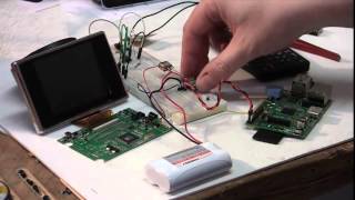
Connect your Raspberry Pi to a breadboard, download some code and create a push-button audio play project.


Puce électronique / Microchip :


Sans fil - Wireless :


Texas instrument :


Ordinateurs :


Logiciels :


Tutoriels :


Autres documentations :
Farnell-MSP430-Hardw..> 29-Jul-2014 10:36 1.1M
![[TXT]](http://www.audentia-gestion.fr/icons/text.gif)
Farnell-LM324-Texas-..> 29-Jul-2014 10:32 1.5M
Farnell-LM386-Low-Vo..> 29-Jul-2014 10:32 1.5M
Farnell-NE5532-Texas..> 29-Jul-2014 10:32 1.5M
Farnell-Hex-Inverter..> 29-Jul-2014 10:31 875K
Farnell-AT90USBKey-H..> 29-Jul-2014 10:31 902K
Farnell-AT89C5131-Ha..> 29-Jul-2014 10:31 1.2M
Farnell-MSP-EXP430F5..> 29-Jul-2014 10:31 1.2M
Farnell-Explorer-16-..> 29-Jul-2014 10:31 1.3M
Farnell-TMP006EVM-Us..> 29-Jul-2014 10:30 1.3M
Farnell-Gertboard-Us..> 29-Jul-2014 10:30 1.4M
Farnell-LMP91051-Use..> 29-Jul-2014 10:30 1.4M
Farnell-Thermometre-..> 29-Jul-2014 10:30 1.4M
Farnell-user-manuel-..> 29-Jul-2014 10:29 1.5M
Farnell-fx-3650P-fx-..> 29-Jul-2014 10:29 1.5M
Farnell-2-GBPS-Diffe..> 28-Jul-2014 17:42 2.7M
Farnell-LMT88-2.4V-1..> 28-Jul-2014 17:42 2.8M
Farnell-Octal-Genera..> 28-Jul-2014 17:42 2.8M
Farnell-Dual-MOSFET-..> 28-Jul-2014 17:41 2.8M
Farnell-TLV320AIC325..> 28-Jul-2014 17:41 2.9M
Farnell-SN54LV4053A-..> 28-Jul-2014 17:20 5.9M
Farnell-TAS1020B-USB..> 28-Jul-2014 17:19 6.2M
Farnell-TPS40060-Wid..> 28-Jul-2014 17:19 6.3M
Farnell-TL082-Wide-B..> 28-Jul-2014 17:16 6.3M
Farnell-RF-short-tra..> 28-Jul-2014 17:16 6.3M
Farnell-maxim-integr..> 28-Jul-2014 17:14 6.4M
Farnell-TSV6390-TSV6..> 28-Jul-2014 17:14 6.4M
Farnell-Fast-Charge-..> 28-Jul-2014 17:12 6.4M
Farnell-NVE-datashee..> 28-Jul-2014 17:12 6.5M
Farnell-Excalibur-Hi..> 28-Jul-2014 17:10 2.4M
Farnell-Excalibur-Hi..> 28-Jul-2014 17:10 2.4M
Farnell-REF102-10V-P..> 28-Jul-2014 17:09 2.4M
Farnell-TMS320F28055..> 28-Jul-2014 17:09 2.7M
Farnell-MULTICOMP-Ra..> 22-Jul-2014 12:35 5.9M
Farnell-RASPBERRY-PI..> 22-Jul-2014 12:35 5.9M
Farnell-Dremel-Exper..> 22-Jul-2014 12:34 1.6M
Farnell-STM32F103x8-..> 22-Jul-2014 12:33 1.6M
Farnell-BD6xxx-PDF.htm 22-Jul-2014 12:33 1.6M
Farnell-L78S-STMicro..> 22-Jul-2014 12:32 1.6M
Farnell-RaspiCam-Doc..> 22-Jul-2014 12:32 1.6M
Farnell-SB520-SB5100..> 22-Jul-2014 12:32 1.6M
Farnell-iServer-Micr..> 22-Jul-2014 12:32 1.6M
Farnell-LUMINARY-MIC..> 22-Jul-2014 12:31 3.6M
Farnell-TEXAS-INSTRU..> 22-Jul-2014 12:31 2.4M
Farnell-TEXAS-INSTRU..> 22-Jul-2014 12:30 4.6M
Farnell-CLASS 1-or-2..> 22-Jul-2014 12:30 4.7M
Farnell-TEXAS-INSTRU..> 22-Jul-2014 12:29 4.8M
Farnell-Evaluating-t..> 22-Jul-2014 12:28 4.9M
Farnell-LM3S6952-Mic..> 22-Jul-2014 12:27 5.9M
Farnell-Keyboard-Mou..> 22-Jul-2014 12:27 5.9M
Farnell-Full-Datashe..> 15-Jul-2014 17:08 951K
Farnell-pmbta13_pmbt..> 15-Jul-2014 17:06 959K
Farnell-EE-SPX303N-4..> 15-Jul-2014 17:06 969K
Farnell-Datasheet-NX..> 15-Jul-2014 17:06 1.0M
Farnell-Datasheet-Fa..> 15-Jul-2014 17:05 1.0M
Farnell-MIDAS-un-tra..> 15-Jul-2014 17:05 1.0M
Farnell-SERIAL-TFT-M..> 15-Jul-2014 17:05 1.0M
Farnell-MCOC1-Farnel..> 15-Jul-2014 17:05 1.0M
Farnell-TMR-2-series..> 15-Jul-2014 16:48 787K
Farnell-DC-DC-Conver..> 15-Jul-2014 16:48 781K
Farnell-Full-Datashe..> 15-Jul-2014 16:47 803K
Farnell-TMLM-Series-..> 15-Jul-2014 16:47 810K
Farnell-TEL-5-Series..> 15-Jul-2014 16:47 814K
Farnell-TXL-series-t..> 15-Jul-2014 16:47 829K
Farnell-TEP-150WI-Se..> 15-Jul-2014 16:47 837K
Farnell-AC-DC-Power-..> 15-Jul-2014 16:47 845K
Farnell-TIS-Instruct..> 15-Jul-2014 16:47 845K
Farnell-TOS-tracopow..> 15-Jul-2014 16:47 852K
Farnell-TCL-DC-traco..> 15-Jul-2014 16:46 858K
Farnell-TIS-series-t..> 15-Jul-2014 16:46 875K
Farnell-TMR-2-Series..> 15-Jul-2014 16:46 897K
Farnell-TMR-3-WI-Ser..> 15-Jul-2014 16:46 939K
Farnell-TEN-8-WI-Ser..> 15-Jul-2014 16:46 939K
Farnell-Full-Datashe..> 15-Jul-2014 16:46 947K
Farnell-HIP4081A-Int..> 07-Jul-2014 19:47 1.0M
Farnell-ISL6251-ISL6..> 07-Jul-2014 19:47 1.1M
Farnell-DG411-DG412-..> 07-Jul-2014 19:47 1.0M
Farnell-3367-ARALDIT..> 07-Jul-2014 19:46 1.2M
Farnell-ICM7228-Inte..> 07-Jul-2014 19:46 1.1M
Farnell-Data-Sheet-K..> 07-Jul-2014 19:46 1.2M
Farnell-Silica-Gel-M..> 07-Jul-2014 19:46 1.2M
Farnell-TKC2-Dusters..> 07-Jul-2014 19:46 1.2M
Farnell-CRC-HANDCLEA..> 07-Jul-2014 19:46 1.2M
Farnell-760G-French-..> 07-Jul-2014 19:45 1.2M
Farnell-Decapant-KF-..> 07-Jul-2014 19:45 1.2M
Farnell-1734-ARALDIT..> 07-Jul-2014 19:45 1.2M
Farnell-Araldite-Fus..> 07-Jul-2014 19:45 1.2M
Farnell-fiche-de-don..> 07-Jul-2014 19:44 1.4M
Farnell-safety-data-..> 07-Jul-2014 19:44 1.4M
Farnell-A-4-Hardener..> 07-Jul-2014 19:44 1.4M
Farnell-CC-Debugger-..> 07-Jul-2014 19:44 1.5M
Farnell-MSP430-Hardw..> 07-Jul-2014 19:43 1.8M
Farnell-SmartRF06-Ev..> 07-Jul-2014 19:43 1.6M
Farnell-CC2531-USB-H..> 07-Jul-2014 19:43 1.8M
Farnell-Alimentation..> 07-Jul-2014 19:43 1.8M
Farnell-BK889B-PONT-..> 07-Jul-2014 19:42 1.8M
Farnell-User-Guide-M..> 07-Jul-2014 19:41 2.0M
Farnell-T672-3000-Se..> 07-Jul-2014 19:41 2.0M
Farnell-0050375063-D..> 18-Jul-2014 17:03 2.5M
Farnell-Mini-Fit-Jr-..> 18-Jul-2014 17:03 2.5M
Farnell-43031-0002-M..> 18-Jul-2014 17:03 2.5M
Farnell-0433751001-D..> 18-Jul-2014 17:02 2.5M
Farnell-Cube-3D-Prin..> 18-Jul-2014 17:02 2.5M
Farnell-MTX-Compact-..> 18-Jul-2014 17:01 2.5M
Farnell-MTX-3250-MTX..> 18-Jul-2014 17:01 2.5M
Farnell-ATtiny26-L-A..> 18-Jul-2014 17:00 2.6M
Farnell-MCP3421-Micr..> 18-Jul-2014 17:00 1.2M
Farnell-LM19-Texas-I..> 18-Jul-2014 17:00 1.2M
Farnell-Data-Sheet-S..> 18-Jul-2014 17:00 1.2M
Farnell-LMH6518-Texa..> 18-Jul-2014 16:59 1.3M
Farnell-AD7719-Low-V..> 18-Jul-2014 16:59 1.4M
Farnell-DAC8143-Data..> 18-Jul-2014 16:59 1.5M
Farnell-BGA7124-400-..> 18-Jul-2014 16:59 1.5M
Farnell-SICK-OPTIC-E..> 18-Jul-2014 16:58 1.5M
Farnell-LT3757-Linea..> 18-Jul-2014 16:58 1.6M
Farnell-LT1961-Linea..> 18-Jul-2014 16:58 1.6M
Farnell-PIC18F2420-2..> 18-Jul-2014 16:57 2.5M
Farnell-DS3231-DS-PD..> 18-Jul-2014 16:57 2.5M
Farnell-RDS-80-PDF.htm 18-Jul-2014 16:57 1.3M
Farnell-AD8300-Data-..> 18-Jul-2014 16:56 1.3M
Farnell-LT6233-Linea..> 18-Jul-2014 16:56 1.3M
Farnell-MAX1365-MAX1..> 18-Jul-2014 16:56 1.4M
Farnell-XPSAF5130-PD..> 18-Jul-2014 16:56 1.4M
Farnell-DP83846A-DsP..> 18-Jul-2014 16:55 1.5M
Farnell-Dremel-Exper..> 18-Jul-2014 16:55 1.6M
Farnell-MCOC1-Farnel..> 16-Jul-2014 09:04 1.0M
Farnell-SL3S1203_121..> 16-Jul-2014 09:04 1.1M
Farnell-PN512-Full-N..> 16-Jul-2014 09:03 1.4M
Farnell-SL3S4011_402..> 16-Jul-2014 09:03 1.1M
Farnell-LPC408x-7x 3..> 16-Jul-2014 09:03 1.6M
Farnell-PCF8574-PCF8..> 16-Jul-2014 09:03 1.7M
Farnell-LPC81xM-32-b..> 16-Jul-2014 09:02 2.0M
Farnell-LPC1769-68-6..> 16-Jul-2014 09:02 1.9M
Farnell-Download-dat..> 16-Jul-2014 09:02 2.2M
Farnell-LPC3220-30-4..> 16-Jul-2014 09:02 2.2M
Farnell-LPC11U3x-32-..> 16-Jul-2014 09:01 2.4M
Farnell-SL3ICS1002-1..> 16-Jul-2014 09:01 2.5M
Farnell-T672-3000-Se..> 08-Jul-2014 18:59 2.0M
Farnell-tesa®pack63..> 08-Jul-2014 18:56 2.0M
Farnell-Encodeur-USB..> 08-Jul-2014 18:56 2.0M
Farnell-CC2530ZDK-Us..> 08-Jul-2014 18:55 2.1M
Farnell-2020-Manuel-..> 08-Jul-2014 18:55 2.1M
Farnell-Synchronous-..> 08-Jul-2014 18:54 2.1M
Farnell-Arithmetic-L..> 08-Jul-2014 18:54 2.1M
Farnell-NA555-NE555-..> 08-Jul-2014 18:53 2.2M
Farnell-4-Bit-Magnit..> 08-Jul-2014 18:53 2.2M
Farnell-LM555-Timer-..> 08-Jul-2014 18:53 2.2M
Farnell-L293d-Texas-..> 08-Jul-2014 18:53 2.2M
Farnell-SN54HC244-SN..> 08-Jul-2014 18:52 2.3M
Farnell-MAX232-MAX23..> 08-Jul-2014 18:52 2.3M
Farnell-High-precisi..> 08-Jul-2014 18:51 2.3M
Farnell-SMU-Instrume..> 08-Jul-2014 18:51 2.3M
Farnell-900-Series-B..> 08-Jul-2014 18:50 2.3M
Farnell-BA-Series-Oh..> 08-Jul-2014 18:50 2.3M
Farnell-UTS-Series-S..> 08-Jul-2014 18:49 2.5M
Farnell-270-Series-O..> 08-Jul-2014 18:49 2.3M
Farnell-UTS-Series-S..> 08-Jul-2014 18:49 2.8M
Farnell-Tiva-C-Serie..> 08-Jul-2014 18:49 2.6M
Farnell-UTO-Souriau-..> 08-Jul-2014 18:48 2.8M
Farnell-Clipper-Seri..> 08-Jul-2014 18:48 2.8M
Farnell-SOURIAU-Cont..> 08-Jul-2014 18:47 3.0M
Farnell-851-Series-P..> 08-Jul-2014 18:47 3.0M
Farnell-SL59830-Inte..> 06-Jul-2014 10:07 1.0M
Farnell-ALF1210-PDF.htm 06-Jul-2014 10:06 4.0M
Farnell-AD7171-16-Bi..> 06-Jul-2014 10:06 1.0M
Farnell-Low-Noise-24..> 06-Jul-2014 10:05 1.0M
Farnell-ESCON-Featur..> 06-Jul-2014 10:05 938K
Farnell-74LCX573-Fai..> 06-Jul-2014 10:05 1.9M
Farnell-1N4148WS-Fai..> 06-Jul-2014 10:04 1.9M
Farnell-FAN6756-Fair..> 06-Jul-2014 10:04 850K
Farnell-Datasheet-Fa..> 06-Jul-2014 10:04 861K
Farnell-ES1F-ES1J-fi..> 06-Jul-2014 10:04 867K
Farnell-QRE1113-Fair..> 06-Jul-2014 10:03 879K
Farnell-2N7002DW-Fai..> 06-Jul-2014 10:03 886K
Farnell-FDC2512-Fair..> 06-Jul-2014 10:03 886K
Farnell-FDV301N-Digi..> 06-Jul-2014 10:03 886K
Farnell-S1A-Fairchil..> 06-Jul-2014 10:03 896K
Farnell-BAV99-Fairch..> 06-Jul-2014 10:03 896K
Farnell-74AC00-74ACT..> 06-Jul-2014 10:03 911K
Farnell-NaPiOn-Panas..> 06-Jul-2014 10:02 911K
Farnell-LQ-RELAYS-AL..> 06-Jul-2014 10:02 924K
Farnell-ev-relays-ae..> 06-Jul-2014 10:02 926K
Farnell-ESCON-Featur..> 06-Jul-2014 10:02 931K
Farnell-Amplifier-In..> 06-Jul-2014 10:02 940K
Farnell-Serial-File-..> 06-Jul-2014 10:02 941K
Farnell-Both-the-Del..> 06-Jul-2014 10:01 948K
Farnell-Videk-PDF.htm 06-Jul-2014 10:01 948K
Farnell-EPCOS-173438..> 04-Jul-2014 10:43 3.3M
Farnell-Sensorless-C..> 04-Jul-2014 10:42 3.3M
Farnell-197.31-KB-Te..> 04-Jul-2014 10:42 3.3M
Farnell-PIC12F609-61..> 04-Jul-2014 10:41 3.7M
Farnell-PADO-semi-au..> 04-Jul-2014 10:41 3.7M
Farnell-03-iec-runds..> 04-Jul-2014 10:40 3.7M
Farnell-ACC-Silicone..> 04-Jul-2014 10:40 3.7M
Farnell-Series-TDS10..> 04-Jul-2014 10:39 4.0M
Farnell-03-iec-runds..> 04-Jul-2014 10:40 3.7M
Farnell-0430300011-D..> 14-Jun-2014 18:13 2.0M
Farnell-06-6544-8-PD..> 26-Mar-2014 17:56 2.7M
Farnell-3M-Polyimide..> 21-Mar-2014 08:09 3.9M
Farnell-3M-VolitionT..> 25-Mar-2014 08:18 3.3M
Farnell-10BQ060-PDF.htm 14-Jun-2014 09:50 2.4M
Farnell-10TPB47M-End..> 14-Jun-2014 18:16 3.4M
Farnell-12mm-Size-In..> 14-Jun-2014 09:50 2.4M
Farnell-24AA024-24LC..> 23-Jun-2014 10:26 3.1M
Farnell-50A-High-Pow..> 20-Mar-2014 17:31 2.9M
Farnell-197.31-KB-Te..> 04-Jul-2014 10:42 3.3M
Farnell-1907-2006-PD..> 26-Mar-2014 17:56 2.7M
Farnell-5910-PDF.htm 25-Mar-2014 08:15 3.0M
Farnell-6517b-Electr..> 29-Mar-2014 11:12 3.3M
Farnell-A-True-Syste..> 29-Mar-2014 11:13 3.3M
Farnell-ACC-Silicone..> 04-Jul-2014 10:40 3.7M
Farnell-AD524-PDF.htm 20-Mar-2014 17:33 2.8M
Farnell-ADL6507-PDF.htm 14-Jun-2014 18:19 3.4M
Farnell-ADSP-21362-A..> 20-Mar-2014 17:34 2.8M
Farnell-ALF1210-PDF.htm 04-Jul-2014 10:39 4.0M
Farnell-ALF1225-12-V..> 01-Apr-2014 07:40 3.4M
Farnell-ALF2412-24-V..> 01-Apr-2014 07:39 3.4M
Farnell-AN10361-Phil..> 23-Jun-2014 10:29 2.1M
Farnell-ARADUR-HY-13..> 26-Mar-2014 17:55 2.8M
Farnell-ARALDITE-201..> 21-Mar-2014 08:12 3.7M
Farnell-ARALDITE-CW-..> 26-Mar-2014 17:56 2.7M
Farnell-ATMEL-8-bit-..> 19-Mar-2014 18:04 2.1M
Farnell-ATMEL-8-bit-..> 11-Mar-2014 07:55 2.1M
Farnell-ATmega640-VA..> 14-Jun-2014 09:49 2.5M
Farnell-ATtiny20-PDF..> 25-Mar-2014 08:19 3.6M
Farnell-ATtiny26-L-A..> 13-Jun-2014 18:40 1.8M
Farnell-Alimentation..> 14-Jun-2014 18:24 2.5M
Farnell-Alimentation..> 01-Apr-2014 07:42 3.4M
Farnell-Amplificateu..> 29-Mar-2014 11:11 3.3M
Farnell-An-Improved-..> 14-Jun-2014 09:49 2.5M
Farnell-Atmel-ATmega..> 19-Mar-2014 18:03 2.2M
Farnell-Avvertenze-e..> 14-Jun-2014 18:20 3.3M
Farnell-BC846DS-NXP-..> 13-Jun-2014 18:42 1.6M
Farnell-BC847DS-NXP-..> 23-Jun-2014 10:24 3.3M
Farnell-BF545A-BF545..> 23-Jun-2014 10:28 2.1M
Farnell-BK2650A-BK26..> 29-Mar-2014 11:10 3.3M
Farnell-BT151-650R-N..> 13-Jun-2014 18:40 1.7M
Farnell-BTA204-800C-..> 13-Jun-2014 18:42 1.6M
Farnell-BUJD203AX-NX..> 13-Jun-2014 18:41 1.7M
Farnell-BYV29F-600-N..> 13-Jun-2014 18:42 1.6M
Farnell-BYV79E-serie..> 10-Mar-2014 16:19 1.6M
Farnell-BZX384-serie..> 23-Jun-2014 10:29 2.1M
Farnell-Battery-GBA-..> 14-Jun-2014 18:13 2.0M
Farnell-C.A-6150-C.A..> 14-Jun-2014 18:24 2.5M
Farnell-C.A 8332B-C...> 01-Apr-2014 07:40 3.4M
Farnell-CC2560-Bluet..> 29-Mar-2014 11:14 2.8M
Farnell-CD4536B-Type..> 14-Jun-2014 18:13 2.0M
Farnell-CIRRUS-LOGIC..> 10-Mar-2014 17:20 2.1M
Farnell-CS5532-34-BS..> 01-Apr-2014 07:39 3.5M
Farnell-Cannon-ZD-PD..> 11-Mar-2014 08:13 2.8M
Farnell-Ceramic-tran..> 14-Jun-2014 18:19 3.4M
Farnell-Circuit-Note..> 26-Mar-2014 18:00 2.8M
Farnell-Circuit-Note..> 26-Mar-2014 18:00 2.8M
Farnell-Cles-electro..> 21-Mar-2014 08:13 3.9M
Farnell-Conception-d..> 11-Mar-2014 07:49 2.4M
Farnell-Connectors-N..> 14-Jun-2014 18:12 2.1M
Farnell-Construction..> 14-Jun-2014 18:25 2.5M
Farnell-Controle-de-..> 11-Mar-2014 08:16 2.8M
Farnell-Cordless-dri..> 14-Jun-2014 18:13 2.0M
Farnell-Current-Tran..> 26-Mar-2014 17:58 2.7M
Farnell-Current-Tran..> 26-Mar-2014 17:58 2.7M
Farnell-Current-Tran..> 26-Mar-2014 17:59 2.7M
Farnell-Current-Tran..> 26-Mar-2014 17:59 2.7M
Farnell-DC-Fan-type-..> 14-Jun-2014 09:48 2.5M
Farnell-DC-Fan-type-..> 14-Jun-2014 09:51 1.8M
Farnell-Davum-TMC-PD..> 14-Jun-2014 18:27 2.4M
Farnell-De-la-puissa..> 29-Mar-2014 11:10 3.3M
Farnell-Directive-re..> 25-Mar-2014 08:16 3.0M
Farnell-Documentatio..> 14-Jun-2014 18:26 2.5M
Farnell-Download-dat..> 13-Jun-2014 18:40 1.8M
Farnell-ECO-Series-T..> 20-Mar-2014 08:14 2.5M
Farnell-ELMA-PDF.htm 29-Mar-2014 11:13 3.3M
Farnell-EMC1182-PDF.htm 25-Mar-2014 08:17 3.0M
Farnell-EPCOS-173438..> 04-Jul-2014 10:43 3.3M
Farnell-EPCOS-Sample..> 11-Mar-2014 07:53 2.2M
Farnell-ES2333-PDF.htm 11-Mar-2014 08:14 2.8M
Farnell-Ed.081002-DA..> 19-Mar-2014 18:02 2.5M
Farnell-F28069-Picco..> 14-Jun-2014 18:14 2.0M
Farnell-F42202-PDF.htm 19-Mar-2014 18:00 2.5M
Farnell-FDS-ITW-Spra..> 14-Jun-2014 18:22 3.3M
Farnell-FICHE-DE-DON..> 10-Mar-2014 16:17 1.6M
Farnell-Fastrack-Sup..> 23-Jun-2014 10:25 3.3M
Farnell-Ferric-Chlor..> 29-Mar-2014 11:14 2.8M
Farnell-Fiche-de-don..> 14-Jun-2014 09:47 2.5M
Farnell-Fiche-de-don..> 14-Jun-2014 18:26 2.5M
Farnell-Fluke-1730-E..> 14-Jun-2014 18:23 2.5M
Farnell-GALVA-A-FROI..> 26-Mar-2014 17:56 2.7M
Farnell-GALVA-MAT-Re..> 26-Mar-2014 17:57 2.7M
Farnell-GN-RELAYS-AG..> 20-Mar-2014 08:11 2.6M
Farnell-HC49-4H-Crys..> 14-Jun-2014 18:20 3.3M
Farnell-HFE1600-Data..> 14-Jun-2014 18:22 3.3M
Farnell-HI-70300-Sol..> 14-Jun-2014 18:27 2.4M
Farnell-HUNTSMAN-Adv..> 10-Mar-2014 16:17 1.7M
Farnell-Haute-vitess..> 11-Mar-2014 08:17 2.4M
Farnell-IP4252CZ16-8..> 13-Jun-2014 18:41 1.7M
Farnell-Instructions..> 19-Mar-2014 18:01 2.5M
Farnell-KSZ8851SNL-S..> 23-Jun-2014 10:28 2.1M
Farnell-L-efficacite..> 11-Mar-2014 07:52 2.3M
Farnell-LCW-CQ7P.CC-..> 25-Mar-2014 08:19 3.2M
Farnell-LME49725-Pow..> 14-Jun-2014 09:49 2.5M
Farnell-LOCTITE-542-..> 25-Mar-2014 08:15 3.0M
Farnell-LOCTITE-3463..> 25-Mar-2014 08:19 3.0M
Farnell-LUXEON-Guide..> 11-Mar-2014 07:52 2.3M
Farnell-Leaded-Trans..> 23-Jun-2014 10:26 3.2M
Farnell-Les-derniers..> 11-Mar-2014 07:50 2.3M
Farnell-Loctite3455-..> 25-Mar-2014 08:16 3.0M
Farnell-Low-cost-Enc..> 13-Jun-2014 18:42 1.7M
Farnell-Lubrifiant-a..> 26-Mar-2014 18:00 2.7M
Farnell-MC3510-PDF.htm 25-Mar-2014 08:17 3.0M
Farnell-MC21605-PDF.htm 11-Mar-2014 08:14 2.8M
Farnell-MCF532x-7x-E..> 29-Mar-2014 11:14 2.8M
Farnell-MICREL-KSZ88..> 11-Mar-2014 07:54 2.2M
Farnell-MICROCHIP-PI..> 19-Mar-2014 18:02 2.5M
Farnell-MOLEX-39-00-..> 10-Mar-2014 17:19 1.9M
Farnell-MOLEX-43020-..> 10-Mar-2014 17:21 1.9M
Farnell-MOLEX-43160-..> 10-Mar-2014 17:21 1.9M
Farnell-MOLEX-87439-..> 10-Mar-2014 17:21 1.9M
Farnell-MPXV7002-Rev..> 20-Mar-2014 17:33 2.8M
Farnell-MX670-MX675-..> 14-Jun-2014 09:46 2.5M
Farnell-Microchip-MC..> 13-Jun-2014 18:27 1.8M
Farnell-Microship-PI..> 11-Mar-2014 07:53 2.2M
Farnell-Midas-Active..> 14-Jun-2014 18:17 3.4M
Farnell-Midas-MCCOG4..> 14-Jun-2014 18:11 2.1M
Farnell-Miniature-Ci..> 26-Mar-2014 17:55 2.8M
Farnell-Mistral-PDF.htm 14-Jun-2014 18:12 2.1M
Farnell-Molex-83421-..> 14-Jun-2014 18:17 3.4M
Farnell-Molex-COMMER..> 14-Jun-2014 18:16 3.4M
Farnell-Molex-Crimp-..> 10-Mar-2014 16:27 1.7M
Farnell-Multi-Functi..> 20-Mar-2014 17:38 3.0M
Farnell-NTE_SEMICOND..> 11-Mar-2014 07:52 2.3M
Farnell-NXP-74VHC126..> 10-Mar-2014 16:17 1.6M
Farnell-NXP-BT136-60..> 11-Mar-2014 07:52 2.3M
Farnell-NXP-PBSS9110..> 10-Mar-2014 17:21 1.9M
Farnell-NXP-PCA9555 ..> 11-Mar-2014 07:54 2.2M
Farnell-NXP-PMBFJ620..> 10-Mar-2014 16:16 1.7M
Farnell-NXP-PSMN1R7-..> 10-Mar-2014 16:17 1.6M
Farnell-NXP-PSMN7R0-..> 10-Mar-2014 17:19 2.1M
Farnell-NXP-TEA1703T..> 11-Mar-2014 08:15 2.8M
Farnell-Nilï¬-sk-E-..> 14-Jun-2014 09:47 2.5M
Farnell-Novembre-201..> 20-Mar-2014 17:38 3.3M
Farnell-OMRON-Master..> 10-Mar-2014 16:26 1.8M
Farnell-OSLON-SSL-Ce..> 19-Mar-2014 18:03 2.1M
Farnell-OXPCIE958-FB..> 13-Jun-2014 18:40 1.8M
Farnell-PADO-semi-au..> 04-Jul-2014 10:41 3.7M
Farnell-PBSS5160T-60..> 19-Mar-2014 18:03 2.1M
Farnell-PDTA143X-ser..> 20-Mar-2014 08:12 2.6M
Farnell-PDTB123TT-NX..> 13-Jun-2014 18:43 1.5M
Farnell-PESD5V0F1BL-..> 13-Jun-2014 18:43 1.5M
Farnell-PESD9X5.0L-P..> 13-Jun-2014 18:43 1.6M
Farnell-PIC12F609-61..> 04-Jul-2014 10:41 3.7M
Farnell-PIC18F2455-2..> 23-Jun-2014 10:27 3.1M
Farnell-PIC24FJ256GB..> 14-Jun-2014 09:51 2.4M
Farnell-PMBT3906-PNP..> 13-Jun-2014 18:44 1.5M
Farnell-PMBT4403-PNP..> 23-Jun-2014 10:27 3.1M
Farnell-PMEG4002EL-N..> 14-Jun-2014 18:18 3.4M
Farnell-PMEG4010CEH-..> 13-Jun-2014 18:43 1.6M
Farnell-Panasonic-15..> 23-Jun-2014 10:29 2.1M
Farnell-Panasonic-EC..> 20-Mar-2014 17:36 2.6M
Farnell-Panasonic-EZ..> 20-Mar-2014 08:10 2.6M
Farnell-Panasonic-Id..> 20-Mar-2014 17:35 2.6M
Farnell-Panasonic-Ne..> 20-Mar-2014 17:36 2.6M
Farnell-Panasonic-Ra..> 20-Mar-2014 17:37 2.6M
Farnell-Panasonic-TS..> 20-Mar-2014 08:12 2.6M
Farnell-Panasonic-Y3..> 20-Mar-2014 08:11 2.6M
Farnell-Pico-Spox-Wi..> 10-Mar-2014 16:16 1.7M
Farnell-Pompes-Charg..> 24-Apr-2014 20:23 3.3M
Farnell-Ponts-RLC-po..> 14-Jun-2014 18:23 3.3M
Farnell-Portable-Ana..> 29-Mar-2014 11:16 2.8M
Farnell-Premier-Farn..> 21-Mar-2014 08:11 3.8M
Farnell-Produit-3430..> 14-Jun-2014 09:48 2.5M
Farnell-Proskit-SS-3..> 10-Mar-2014 16:26 1.8M
Farnell-Puissance-ut..> 11-Mar-2014 07:49 2.4M
Farnell-Q48-PDF.htm 23-Jun-2014 10:29 2.1M
Farnell-Radial-Lead-..> 20-Mar-2014 08:12 2.6M
Farnell-Realiser-un-..> 11-Mar-2014 07:51 2.3M
Farnell-Reglement-RE..> 21-Mar-2014 08:08 3.9M
Farnell-Repartiteurs..> 14-Jun-2014 18:26 2.5M
Farnell-S-TRI-SWT860..> 21-Mar-2014 08:11 3.8M
Farnell-SB175-Connec..> 11-Mar-2014 08:14 2.8M
Farnell-SMBJ-Transil..> 29-Mar-2014 11:12 3.3M
Farnell-SOT-23-Multi..> 11-Mar-2014 07:51 2.3M
Farnell-SPLC780A1-16..> 14-Jun-2014 18:25 2.5M
Farnell-SSC7102-Micr..> 23-Jun-2014 10:25 3.2M
Farnell-SVPE-series-..> 14-Jun-2014 18:15 2.0M
Farnell-Sensorless-C..> 04-Jul-2014 10:42 3.3M
Farnell-Septembre-20..> 20-Mar-2014 17:46 3.7M
Farnell-Serie-PicoSc..> 19-Mar-2014 18:01 2.5M
Farnell-Serie-Standa..> 14-Jun-2014 18:23 3.3M
Farnell-Series-2600B..> 20-Mar-2014 17:30 3.0M
Farnell-Series-TDS10..> 04-Jul-2014 10:39 4.0M
Farnell-Signal-PCB-R..> 14-Jun-2014 18:11 2.1M
Farnell-Strangkuhlko..> 21-Mar-2014 08:09 3.9M
Farnell-Supercapacit..> 26-Mar-2014 17:57 2.7M
Farnell-TDK-Lambda-H..> 14-Jun-2014 18:21 3.3M
Farnell-TEKTRONIX-DP..> 10-Mar-2014 17:20 2.0M
Farnell-Tektronix-AC..> 13-Jun-2014 18:44 1.5M
Farnell-Telemetres-l..> 20-Mar-2014 17:46 3.7M
Farnell-Termometros-..> 14-Jun-2014 18:14 2.0M
Farnell-The-essentia..> 10-Mar-2014 16:27 1.7M
Farnell-U2270B-PDF.htm 14-Jun-2014 18:15 3.4M
Farnell-USB-Buccanee..> 14-Jun-2014 09:48 2.5M
Farnell-USB1T11A-PDF..> 19-Mar-2014 18:03 2.1M
Farnell-V4N-PDF.htm 14-Jun-2014 18:11 2.1M
Farnell-WetTantalum-..> 11-Mar-2014 08:14 2.8M
Farnell-XPS-AC-Octop..> 14-Jun-2014 18:11 2.1M
Farnell-XPS-MC16-XPS..> 11-Mar-2014 08:15 2.8M
Farnell-YAGEO-DATA-S..> 11-Mar-2014 08:13 2.8M
Farnell-ZigBee-ou-le..> 11-Mar-2014 07:50 2.4M
Farnell-celpac-SUL84..> 21-Mar-2014 08:11 3.8M
Farnell-china_rohs_o..> 21-Mar-2014 10:04 3.9M
Farnell-cree-Xlamp-X..> 20-Mar-2014 17:34 2.8M
Farnell-cree-Xlamp-X..> 20-Mar-2014 17:35 2.7M
Farnell-cree-Xlamp-X..> 20-Mar-2014 17:31 2.9M
Farnell-cree-Xlamp-m..> 20-Mar-2014 17:32 2.9M
Farnell-cree-Xlamp-m..> 20-Mar-2014 17:32 2.9M
Farnell-ir1150s_fr.p..> 29-Mar-2014 11:11 3.3M
Farnell-manual-bus-p..> 10-Mar-2014 16:29 1.9M
Farnell-propose-plus..> 11-Mar-2014 08:19 2.8M
Farnell-techfirst_se..> 21-Mar-2014 08:08 3.9M
Farnell-testo-205-20..> 20-Mar-2014 17:37 3.0M
Farnell-testo-470-Fo..> 20-Mar-2014 17:38 3.0M
Farnell-uC-OS-III-Br..> 10-Mar-2014 17:20 2.0M
Sefram-7866HD.pdf-PD..> 29-Mar-2014 11:46 472K
Sefram-CAT_ENREGISTR..> 29-Mar-2014 11:46 461K
Sefram-CAT_MESUREURS..> 29-Mar-2014 11:46 435K
Sefram-GUIDE_SIMPLIF..> 29-Mar-2014 11:46 481K
Sefram-GUIDE_SIMPLIF..> 29-Mar-2014 11:46 442K
Sefram-GUIDE_SIMPLIF..> 29-Mar-2014 11:46 422K
Sefram-SP270.pdf-PDF..> 29-Mar-2014 11:46 464K
STM32F405xx
STM32F407xx
ARM Cortex-M4 32b MCU+FPU, 210DMIPS, up to 1MB Flash/192+4KB RAM, USB
OTG HS/FS, Ethernet, 17 TIMs, 3 ADCs, 15 comm. interfaces & camera
Datasheet - production data
Features
• Core: ARM 32-bit Cortex™-M4 CPU with FPU,
Adaptive real-time accelerator (ART
Accelerator™) allowing 0-wait state execution
from Flash memory, frequency up to 168 MHz,
memory protection unit, 210 DMIPS/
1.25 DMIPS/MHz (Dhrystone 2.1), and DSP
instructions
• Memories
– Up to 1 Mbyte of Flash memory
– Up to 192+4 Kbytes of SRAM including 64-
Kbyte of CCM (core coupled memory) data
RAM
– Flexible static memory controller
supporting Compact Flash, SRAM,
PSRAM, NOR and NAND memories
• LCD parallel interface, 8080/6800 modes
• Clock, reset and supply management
– 1.8 V to 3.6 V application supply and I/Os
– POR, PDR, PVD and BOR
– 4-to-26 MHz crystal oscillator
– Internal 16 MHz factory-trimmed RC (1%
accuracy)
– 32 kHz oscillator for RTC with calibration
– Internal 32 kHz RC with calibration
• Low power
– Sleep, Stop and Standby modes
– VBAT supply for RTC, 20×32 bit backup
registers + optional 4 KB backup SRAM
• 3×12-bit, 2.4 MSPS A/D converters: up to 24
channels and 7.2 MSPS in triple interleaved
mode
• 2×12-bit D/A converters
• General-purpose DMA: 16-stream DMA
controller with FIFOs and burst support
• Up to 17 timers: up to twelve 16-bit and two 32-
bit timers up to 168 MHz, each with up to 4
IC/OC/PWM or pulse counter and quadrature
(incremental) encoder input
• Debug mode
– Serial wire debug (SWD) & JTAG
interfaces
– Cortex-M4 Embedded Trace Macrocell™
• Up to 140 I/O ports with interrupt capability
– Up to 136 fast I/Os up to 84 MHz
– Up to 138 5 V-tolerant I/Os
• Up to 15 communication interfaces
– Up to 3 × I2C interfaces (SMBus/PMBus)
– Up to 4 USARTs/2 UARTs (10.5 Mbit/s, ISO
7816 interface, LIN, IrDA, modem control)
– Up to 3 SPIs (42 Mbits/s), 2 with muxed
full-duplex I2S to achieve audio class
accuracy via internal audio PLL or external
clock
– 2 × CAN interfaces (2.0B Active)
– SDIO interface
• Advanced connectivity
– USB 2.0 full-speed device/host/OTG
controller with on-chip PHY
– USB 2.0 high-speed/full-speed
device/host/OTG controller with dedicated
DMA, on-chip full-speed PHY and ULPI
– 10/100 Ethernet MAC with dedicated DMA:
supports IEEE 1588v2 hardware, MII/RMII
• 8- to 14-bit parallel camera interface up to
54 Mbytes/s
• True random number generator
• CRC calculation unit
• 96-bit unique ID
• RTC: subsecond accuracy, hardware calendar
LQFP64 (10 × 10 mm)
LQFP100 (14 × 14 mm)
LQFP144 (20 × 20 mm)
FBGA
UFBGA176
(10 × 10 mm)
LQFP176 (24 × 24 mm)
WLCSP90
Table 1. Device summary
Reference Part number
STM32F405xx STM32F405RG, STM32F405VG, STM32F405ZG,
STM32F405OG, STM32F405OE
STM32F407xx STM32F407VG, STM32F407IG, STM32F407ZG,
STM32F407VE, STM32F407ZE, STM32F407IE
www.st.com
Contents STM32F405xx, STM32F407xx
2/185 DocID022152 Rev 4
Contents
1 Introduction . . . . . . . . . . . . . . . . . . . . . . . . . . . . . . . . . . . . . . . . . . . . . . . 11
2 Description . . . . . . . . . . . . . . . . . . . . . . . . . . . . . . . . . . . . . . . . . . . . . . . . 12
2.1 Full compatibility throughout the family . . . . . . . . . . . . . . . . . . . . . . . . . . 15
2.2 Device overview . . . . . . . . . . . . . . . . . . . . . . . . . . . . . . . . . . . . . . . . . . . . 18
2.2.1 ARM® Cortex™-M4F core with embedded Flash and SRAM . . . . . . . . 19
2.2.2 Adaptive real-time memory accelerator (ART Accelerator™) . . . . . . . . 19
2.2.3 Memory protection unit . . . . . . . . . . . . . . . . . . . . . . . . . . . . . . . . . . . . . 19
2.2.4 Embedded Flash memory . . . . . . . . . . . . . . . . . . . . . . . . . . . . . . . . . . . 19
2.2.5 CRC (cyclic redundancy check) calculation unit . . . . . . . . . . . . . . . . . . 20
2.2.6 Embedded SRAM . . . . . . . . . . . . . . . . . . . . . . . . . . . . . . . . . . . . . . . . . 20
2.2.7 Multi-AHB bus matrix . . . . . . . . . . . . . . . . . . . . . . . . . . . . . . . . . . . . . . . 20
2.2.8 DMA controller (DMA) . . . . . . . . . . . . . . . . . . . . . . . . . . . . . . . . . . . . . . 21
2.2.9 Flexible static memory controller (FSMC) . . . . . . . . . . . . . . . . . . . . . . . 22
2.2.10 Nested vectored interrupt controller (NVIC) . . . . . . . . . . . . . . . . . . . . . . 22
2.2.11 External interrupt/event controller (EXTI) . . . . . . . . . . . . . . . . . . . . . . . 22
2.2.12 Clocks and startup . . . . . . . . . . . . . . . . . . . . . . . . . . . . . . . . . . . . . . . . . 22
2.2.13 Boot modes . . . . . . . . . . . . . . . . . . . . . . . . . . . . . . . . . . . . . . . . . . . . . . 23
2.2.14 Power supply schemes . . . . . . . . . . . . . . . . . . . . . . . . . . . . . . . . . . . . . 23
2.2.15 Power supply supervisor . . . . . . . . . . . . . . . . . . . . . . . . . . . . . . . . . . . . 23
2.2.16 Voltage regulator . . . . . . . . . . . . . . . . . . . . . . . . . . . . . . . . . . . . . . . . . . 25
2.2.17 Regulator ON/OFF and internal reset ON/OFF availability . . . . . . . . . . 28
2.2.18 Real-time clock (RTC), backup SRAM and backup registers . . . . . . . . 28
2.2.19 Low-power modes . . . . . . . . . . . . . . . . . . . . . . . . . . . . . . . . . . . . . . . . . 29
2.2.20 VBAT operation . . . . . . . . . . . . . . . . . . . . . . . . . . . . . . . . . . . . . . . . . . . . 30
2.2.21 Timers and watchdogs . . . . . . . . . . . . . . . . . . . . . . . . . . . . . . . . . . . . . . 30
2.2.22 Inter-integrated circuit interface (I²C) . . . . . . . . . . . . . . . . . . . . . . . . . . 33
2.2.23 Universal synchronous/asynchronous receiver transmitters (USART) . 33
2.2.24 Serial peripheral interface (SPI) . . . . . . . . . . . . . . . . . . . . . . . . . . . . . . . 34
2.2.25 Inter-integrated sound (I2S) . . . . . . . . . . . . . . . . . . . . . . . . . . . . . . . . . . 34
2.2.26 Audio PLL (PLLI2S) . . . . . . . . . . . . . . . . . . . . . . . . . . . . . . . . . . . . . . . . 34
2.2.27 Secure digital input/output interface (SDIO) . . . . . . . . . . . . . . . . . . . . . 35
2.2.28 Ethernet MAC interface with dedicated DMA and IEEE 1588 support . 35
2.2.29 Controller area network (bxCAN) . . . . . . . . . . . . . . . . . . . . . . . . . . . . . . 36
DocID022152 Rev 4 3/185
STM32F405xx, STM32F407xx Contents
2.2.30 Universal serial bus on-the-go full-speed (OTG_FS) . . . . . . . . . . . . . . . 36
2.2.31 Universal serial bus on-the-go high-speed (OTG_HS) . . . . . . . . . . . . . 36
2.2.32 Digital camera interface (DCMI) . . . . . . . . . . . . . . . . . . . . . . . . . . . . . . 37
2.2.33 Random number generator (RNG) . . . . . . . . . . . . . . . . . . . . . . . . . . . . 37
2.2.34 General-purpose input/outputs (GPIOs) . . . . . . . . . . . . . . . . . . . . . . . . 37
2.2.35 Analog-to-digital converters (ADCs) . . . . . . . . . . . . . . . . . . . . . . . . . . . 37
2.2.36 Temperature sensor . . . . . . . . . . . . . . . . . . . . . . . . . . . . . . . . . . . . . . . . 37
2.2.37 Digital-to-analog converter (DAC) . . . . . . . . . . . . . . . . . . . . . . . . . . . . . 38
2.2.38 Serial wire JTAG debug port (SWJ-DP) . . . . . . . . . . . . . . . . . . . . . . . . . 38
2.2.39 Embedded Trace Macrocell™ . . . . . . . . . . . . . . . . . . . . . . . . . . . . . . . . 38
3 Pinouts and pin description . . . . . . . . . . . . . . . . . . . . . . . . . . . . . . . . . . 39
4 Memory mapping . . . . . . . . . . . . . . . . . . . . . . . . . . . . . . . . . . . . . . . . . . . 69
5 Electrical characteristics . . . . . . . . . . . . . . . . . . . . . . . . . . . . . . . . . . . . 74
5.1 Parameter conditions . . . . . . . . . . . . . . . . . . . . . . . . . . . . . . . . . . . . . . . . 74
5.1.1 Minimum and maximum values . . . . . . . . . . . . . . . . . . . . . . . . . . . . . . . 74
5.1.2 Typical values . . . . . . . . . . . . . . . . . . . . . . . . . . . . . . . . . . . . . . . . . . . . 74
5.1.3 Typical curves . . . . . . . . . . . . . . . . . . . . . . . . . . . . . . . . . . . . . . . . . . . . 74
5.1.4 Loading capacitor . . . . . . . . . . . . . . . . . . . . . . . . . . . . . . . . . . . . . . . . . 74
5.1.5 Pin input voltage . . . . . . . . . . . . . . . . . . . . . . . . . . . . . . . . . . . . . . . . . . 74
5.1.6 Power supply scheme . . . . . . . . . . . . . . . . . . . . . . . . . . . . . . . . . . . . . . 75
5.1.7 Current consumption measurement . . . . . . . . . . . . . . . . . . . . . . . . . . . 76
5.2 Absolute maximum ratings . . . . . . . . . . . . . . . . . . . . . . . . . . . . . . . . . . . . 76
5.3 Operating conditions . . . . . . . . . . . . . . . . . . . . . . . . . . . . . . . . . . . . . . . . 77
5.3.1 General operating conditions . . . . . . . . . . . . . . . . . . . . . . . . . . . . . . . . . 77
5.3.2 VCAP_1/VCAP_2 external capacitor . . . . . . . . . . . . . . . . . . . . . . . . . . . 79
5.3.3 Operating conditions at power-up / power-down (regulator ON) . . . . . . 80
5.3.4 Operating conditions at power-up / power-down (regulator OFF) . . . . . 80
5.3.5 Embedded reset and power control block characteristics . . . . . . . . . . . 80
5.3.6 Supply current characteristics . . . . . . . . . . . . . . . . . . . . . . . . . . . . . . . . 82
5.3.7 Wakeup time from low-power mode . . . . . . . . . . . . . . . . . . . . . . . . . . . 95
5.3.8 External clock source characteristics . . . . . . . . . . . . . . . . . . . . . . . . . . . 96
5.3.9 Internal clock source characteristics . . . . . . . . . . . . . . . . . . . . . . . . . . . 99
5.3.10 PLL characteristics . . . . . . . . . . . . . . . . . . . . . . . . . . . . . . . . . . . . . . . 100
5.3.11 PLL spread spectrum clock generation (SSCG) characteristics . . . . . 102
Contents STM32F405xx, STM32F407xx
4/185 DocID022152 Rev 4
5.3.12 Memory characteristics . . . . . . . . . . . . . . . . . . . . . . . . . . . . . . . . . . . . 104
5.3.13 EMC characteristics . . . . . . . . . . . . . . . . . . . . . . . . . . . . . . . . . . . . . . . 106
5.3.14 Absolute maximum ratings (electrical sensitivity) . . . . . . . . . . . . . . . . 108
5.3.15 I/O current injection characteristics . . . . . . . . . . . . . . . . . . . . . . . . . . . 109
5.3.16 I/O port characteristics . . . . . . . . . . . . . . . . . . . . . . . . . . . . . . . . . . . . . 109
5.3.17 NRST pin characteristics . . . . . . . . . . . . . . . . . . . . . . . . . . . . . . . . . . . 113
5.3.18 TIM timer characteristics . . . . . . . . . . . . . . . . . . . . . . . . . . . . . . . . . . . 114
5.3.19 Communications interfaces . . . . . . . . . . . . . . . . . . . . . . . . . . . . . . . . . 116
5.3.20 12-bit ADC characteristics . . . . . . . . . . . . . . . . . . . . . . . . . . . . . . . . . . 129
5.3.21 Temperature sensor characteristics . . . . . . . . . . . . . . . . . . . . . . . . . . . 134
5.3.22 VBAT monitoring characteristics . . . . . . . . . . . . . . . . . . . . . . . . . . . . . . 134
5.3.23 Embedded reference voltage . . . . . . . . . . . . . . . . . . . . . . . . . . . . . . . . 135
5.3.24 DAC electrical characteristics . . . . . . . . . . . . . . . . . . . . . . . . . . . . . . . 135
5.3.25 FSMC characteristics . . . . . . . . . . . . . . . . . . . . . . . . . . . . . . . . . . . . . . 137
5.3.26 Camera interface (DCMI) timing specifications . . . . . . . . . . . . . . . . . . 155
5.3.27 SD/SDIO MMC card host interface (SDIO) characteristics . . . . . . . . . 156
5.3.28 RTC characteristics . . . . . . . . . . . . . . . . . . . . . . . . . . . . . . . . . . . . . . . 157
6 Package characteristics . . . . . . . . . . . . . . . . . . . . . . . . . . . . . . . . . . . . 158
6.1 Package mechanical data . . . . . . . . . . . . . . . . . . . . . . . . . . . . . . . . . . . 158
6.2 Thermal characteristics . . . . . . . . . . . . . . . . . . . . . . . . . . . . . . . . . . . . . 169
7 Part numbering . . . . . . . . . . . . . . . . . . . . . . . . . . . . . . . . . . . . . . . . . . . 170
Appendix A Application block diagrams . . . . . . . . . . . . . . . . . . . . . . . . . . . . . . 171
A.1 USB OTG full speed (FS) interface solutions . . . . . . . . . . . . . . . . . . . . . 171
A.2 USB OTG high speed (HS) interface solutions . . . . . . . . . . . . . . . . . . . . 173
A.3 Ethernet interface solutions. . . . . . . . . . . . . . . . . . . . . . . . . . . . . . . . . . . 174
8 Revision history . . . . . . . . . . . . . . . . . . . . . . . . . . . . . . . . . . . . . . . . . . 176
DocID022152 Rev 4 5/185
STM32F405xx, STM32F407xx List of tables
List of tables
Table 1. Device summary . . . . . . . . . . . . . . . . . . . . . . . . . . . . . . . . . . . . . . . . . . . . . . . . . . . . . . . . . . 1
Table 2. STM32F405xx and STM32F407xx: features and peripheral counts. . . . . . . . . . . . . . . . . . 13
Table 3. Regulator ON/OFF and internal reset ON/OFF availability. . . . . . . . . . . . . . . . . . . . . . . . . 28
Table 4. Timer feature comparison. . . . . . . . . . . . . . . . . . . . . . . . . . . . . . . . . . . . . . . . . . . . . . . . . . 30
Table 5. USART feature comparison . . . . . . . . . . . . . . . . . . . . . . . . . . . . . . . . . . . . . . . . . . . . . . . . 34
Table 6. Legend/abbreviations used in the pinout table . . . . . . . . . . . . . . . . . . . . . . . . . . . . . . . . . . 44
Table 7. STM32F40x pin and ball definitions . . . . . . . . . . . . . . . . . . . . . . . . . . . . . . . . . . . . . . . . . . 45
Table 8. FSMC pin definition . . . . . . . . . . . . . . . . . . . . . . . . . . . . . . . . . . . . . . . . . . . . . . . . . . . . . . 57
Table 9. Alternate function mapping . . . . . . . . . . . . . . . . . . . . . . . . . . . . . . . . . . . . . . . . . . . . . . . . . 60
Table 10. STM32F40x register boundary addresses . . . . . . . . . . . . . . . . . . . . . . . . . . . . . . . . . . . . . 70
Table 11. Voltage characteristics . . . . . . . . . . . . . . . . . . . . . . . . . . . . . . . . . . . . . . . . . . . . . . . . . . . . 76
Table 12. Current characteristics . . . . . . . . . . . . . . . . . . . . . . . . . . . . . . . . . . . . . . . . . . . . . . . . . . . . 77
Table 13. Thermal characteristics. . . . . . . . . . . . . . . . . . . . . . . . . . . . . . . . . . . . . . . . . . . . . . . . . . . . 77
Table 14. General operating conditions . . . . . . . . . . . . . . . . . . . . . . . . . . . . . . . . . . . . . . . . . . . . . . . 77
Table 15. Limitations depending on the operating power supply range . . . . . . . . . . . . . . . . . . . . . . . 79
Table 16. VCAP_1/VCAP_2 operating conditions . . . . . . . . . . . . . . . . . . . . . . . . . . . . . . . . . . . . . . . 80
Table 17. Operating conditions at power-up / power-down (regulator ON) . . . . . . . . . . . . . . . . . . . . 80
Table 18. Operating conditions at power-up / power-down (regulator OFF). . . . . . . . . . . . . . . . . . . . 80
Table 19. Embedded reset and power control block characteristics. . . . . . . . . . . . . . . . . . . . . . . . . . 81
Table 20. Typical and maximum current consumption in Run mode, code with data processing
running from Flash memory (ART accelerator enabled) or RAM . . . . . . . . . . . . . . . . . . . 83
Table 21. Typical and maximum current consumption in Run mode, code with data processing
running from Flash memory (ART accelerator disabled) . . . . . . . . . . . . . . . . . . . . . . . . . . 84
Table 22. Typical and maximum current consumption in Sleep mode . . . . . . . . . . . . . . . . . . . . . . . . 87
Table 23. Typical and maximum current consumptions in Stop mode . . . . . . . . . . . . . . . . . . . . . . . . 88
Table 24. Typical and maximum current consumptions in Standby mode . . . . . . . . . . . . . . . . . . . . . 88
Table 25. Typical and maximum current consumptions in VBAT mode. . . . . . . . . . . . . . . . . . . . . . . . 89
Table 26. Switching output I/O current consumption . . . . . . . . . . . . . . . . . . . . . . . . . . . . . . . . . . . . . 92
Table 27. Peripheral current consumption . . . . . . . . . . . . . . . . . . . . . . . . . . . . . . . . . . . . . . . . . . . . . 93
Table 28. Low-power mode wakeup timings . . . . . . . . . . . . . . . . . . . . . . . . . . . . . . . . . . . . . . . . . . . 95
Table 29. High-speed external user clock characteristics. . . . . . . . . . . . . . . . . . . . . . . . . . . . . . . . . . 96
Table 30. Low-speed external user clock characteristics . . . . . . . . . . . . . . . . . . . . . . . . . . . . . . . . . . 96
Table 31. HSE 4-26 MHz oscillator characteristics . . . . . . . . . . . . . . . . . . . . . . . . . . . . . . . . . . . . . . 98
Table 32. LSE oscillator characteristics (fLSE = 32.768 kHz) . . . . . . . . . . . . . . . . . . . . . . . . . . . . . . . 99
Table 33. HSI oscillator characteristics . . . . . . . . . . . . . . . . . . . . . . . . . . . . . . . . . . . . . . . . . . . . . . . 99
Table 34. LSI oscillator characteristics . . . . . . . . . . . . . . . . . . . . . . . . . . . . . . . . . . . . . . . . . . . . . . 100
Table 35. Main PLL characteristics. . . . . . . . . . . . . . . . . . . . . . . . . . . . . . . . . . . . . . . . . . . . . . . . . . 101
Table 36. PLLI2S (audio PLL) characteristics . . . . . . . . . . . . . . . . . . . . . . . . . . . . . . . . . . . . . . . . . 101
Table 37. SSCG parameters constraint . . . . . . . . . . . . . . . . . . . . . . . . . . . . . . . . . . . . . . . . . . . . . . 102
Table 38. Flash memory characteristics . . . . . . . . . . . . . . . . . . . . . . . . . . . . . . . . . . . . . . . . . . . . . . 104
Table 39. Flash memory programming. . . . . . . . . . . . . . . . . . . . . . . . . . . . . . . . . . . . . . . . . . . . . . . 104
Table 40. Flash memory programming with VPP . . . . . . . . . . . . . . . . . . . . . . . . . . . . . . . . . . . . . . . . . . . . . . . . . . 106
Table 41. Flash memory endurance and data retention . . . . . . . . . . . . . . . . . . . . . . . . . . . . . . . . . . 106
Table 42. EMS characteristics . . . . . . . . . . . . . . . . . . . . . . . . . . . . . . . . . . . . . . . . . . . . . . . . . . . . . 107
Table 43. EMI characteristics . . . . . . . . . . . . . . . . . . . . . . . . . . . . . . . . . . . . . . . . . . . . . . . . . . . . . . 108
Table 44. ESD absolute maximum ratings . . . . . . . . . . . . . . . . . . . . . . . . . . . . . . . . . . . . . . . . . . . . 108
Table 45. Electrical sensitivities . . . . . . . . . . . . . . . . . . . . . . . . . . . . . . . . . . . . . . . . . . . . . . . . . . . . 109
Table 46. I/O current injection susceptibility . . . . . . . . . . . . . . . . . . . . . . . . . . . . . . . . . . . . . . . . . . . 109
List of tables STM32F405xx, STM32F407xx
6/185 DocID022152 Rev 4
Table 47. I/O static characteristics . . . . . . . . . . . . . . . . . . . . . . . . . . . . . . . . . . . . . . . . . . . . . . . . . . 110
Table 48. Output voltage characteristics . . . . . . . . . . . . . . . . . . . . . . . . . . . . . . . . . . . . . . . . . . . . . 111
Table 49. I/O AC characteristics . . . . . . . . . . . . . . . . . . . . . . . . . . . . . . . . . . . . . . . . . . . . . . . . . . . . 112
Table 50. NRST pin characteristics . . . . . . . . . . . . . . . . . . . . . . . . . . . . . . . . . . . . . . . . . . . . . . . . . 114
Table 51. Characteristics of TIMx connected to the APB1 domain . . . . . . . . . . . . . . . . . . . . . . . . . 115
Table 52. Characteristics of TIMx connected to the APB2 domain . . . . . . . . . . . . . . . . . . . . . . . . . 116
Table 53. I2C characteristics. . . . . . . . . . . . . . . . . . . . . . . . . . . . . . . . . . . . . . . . . . . . . . . . . . . . . . . 116
Table 54. SCL frequency (fPCLK1= 42 MHz.,VDD = 3.3 V) . . . . . . . . . . . . . . . . . . . . . . . . . . . . . . . . 118
Table 55. SPI dynamic characteristics . . . . . . . . . . . . . . . . . . . . . . . . . . . . . . . . . . . . . . . . . . . . . . . 118
Table 56. I2S dynamic characteristics . . . . . . . . . . . . . . . . . . . . . . . . . . . . . . . . . . . . . . . . . . . . . . . 122
Table 57. USB OTG FS startup time . . . . . . . . . . . . . . . . . . . . . . . . . . . . . . . . . . . . . . . . . . . . . . . . 124
Table 58. USB OTG FS DC electrical characteristics. . . . . . . . . . . . . . . . . . . . . . . . . . . . . . . . . . . . 124
Table 59. USB OTG FS electrical characteristics. . . . . . . . . . . . . . . . . . . . . . . . . . . . . . . . . . . . . . . 125
Table 60. USB HS DC electrical characteristics . . . . . . . . . . . . . . . . . . . . . . . . . . . . . . . . . . . . . . . . 125
Table 61. USB HS clock timing parameters . . . . . . . . . . . . . . . . . . . . . . . . . . . . . . . . . . . . . . . . . . . 125
Table 62. ULPI timing . . . . . . . . . . . . . . . . . . . . . . . . . . . . . . . . . . . . . . . . . . . . . . . . . . . . . . . . . . . . 126
Table 63. Ethernet DC electrical characteristics . . . . . . . . . . . . . . . . . . . . . . . . . . . . . . . . . . . . . . . . 127
Table 64. Dynamic characteristics: Ehternet MAC signals for SMI. . . . . . . . . . . . . . . . . . . . . . . . . . 127
Table 65. Dynamic characteristics: Ethernet MAC signals for RMII . . . . . . . . . . . . . . . . . . . . . . . . . 128
Table 66. Dynamic characteristics: Ethernet MAC signals for MII . . . . . . . . . . . . . . . . . . . . . . . . . . 128
Table 67. ADC characteristics . . . . . . . . . . . . . . . . . . . . . . . . . . . . . . . . . . . . . . . . . . . . . . . . . . . . . 129
Table 68. ADC accuracy at fADC = 30 MHz . . . . . . . . . . . . . . . . . . . . . . . . . . . . . . . . . . . . . . . . . . . 131
Table 69. Temperature sensor characteristics . . . . . . . . . . . . . . . . . . . . . . . . . . . . . . . . . . . . . . . . . 134
Table 70. Temperature sensor calibration values. . . . . . . . . . . . . . . . . . . . . . . . . . . . . . . . . . . . . . . 134
Table 71. VBAT monitoring characteristics . . . . . . . . . . . . . . . . . . . . . . . . . . . . . . . . . . . . . . . . . . . . 134
Table 72. Embedded internal reference voltage. . . . . . . . . . . . . . . . . . . . . . . . . . . . . . . . . . . . . . . . 135
Table 73. Internal reference voltage calibration values . . . . . . . . . . . . . . . . . . . . . . . . . . . . . . . . . . 135
Table 74. DAC characteristics . . . . . . . . . . . . . . . . . . . . . . . . . . . . . . . . . . . . . . . . . . . . . . . . . . . . . 135
Table 75. Asynchronous non-multiplexed SRAM/PSRAM/NOR read timings . . . . . . . . . . . . . . . . . 138
Table 76. Asynchronous non-multiplexed SRAM/PSRAM/NOR write timings . . . . . . . . . . . . . . . . . 139
Table 77. Asynchronous multiplexed PSRAM/NOR read timings. . . . . . . . . . . . . . . . . . . . . . . . . . . 140
Table 78. Asynchronous multiplexed PSRAM/NOR write timings . . . . . . . . . . . . . . . . . . . . . . . . . . 141
Table 79. Synchronous multiplexed NOR/PSRAM read timings . . . . . . . . . . . . . . . . . . . . . . . . . . . 143
Table 80. Synchronous multiplexed PSRAM write timings. . . . . . . . . . . . . . . . . . . . . . . . . . . . . . . . 144
Table 81. Synchronous non-multiplexed NOR/PSRAM read timings . . . . . . . . . . . . . . . . . . . . . . . . 145
Table 82. Synchronous non-multiplexed PSRAM write timings . . . . . . . . . . . . . . . . . . . . . . . . . . . . 147
Table 83. Switching characteristics for PC Card/CF read and write cycles
in attribute/common space. . . . . . . . . . . . . . . . . . . . . . . . . . . . . . . . . . . . . . . . . . . . . . . . 151
Table 84. Switching characteristics for PC Card/CF read and write cycles
in I/O space . . . . . . . . . . . . . . . . . . . . . . . . . . . . . . . . . . . . . . . . . . . . . . . . . . . . . . . . . . . 152
Table 85. Switching characteristics for NAND Flash read cycles . . . . . . . . . . . . . . . . . . . . . . . . . . . 154
Table 86. Switching characteristics for NAND Flash write cycles. . . . . . . . . . . . . . . . . . . . . . . . . . . 155
Table 87. DCMI characteristics. . . . . . . . . . . . . . . . . . . . . . . . . . . . . . . . . . . . . . . . . . . . . . . . . . . . . 155
Table 88. Dynamic characteristics: SD / MMC characteristics . . . . . . . . . . . . . . . . . . . . . . . . . . . . . 157
Table 89. RTC characteristics . . . . . . . . . . . . . . . . . . . . . . . . . . . . . . . . . . . . . . . . . . . . . . . . . . . . . 157
Table 90. WLCSP90 - 0.400 mm pitch wafer level chip size package mechanical data . . . . . . . . . 159
Table 91. LQFP64 – 10 x 10 mm 64 pin low-profile quad flat package mechanical data . . . . . . . . . 160
Table 92. LQPF100 – 14 x 14 mm 100-pin low-profile quad flat package mechanical data. . . . . . . 162
Table 93. LQFP144, 20 x 20 mm, 144-pin low-profile quad flat package mechanical data . . . . . . . 164
Table 94. UFBGA176+25 - ultra thin fine pitch ball grid array 10 × 10 × 0.6 mm
mechanical data . . . . . . . . . . . . . . . . . . . . . . . . . . . . . . . . . . . . . . . . . . . . . . . . . . . . . . . . 166
Table 95. LQFP176, 24 x 24 mm, 176-pin low-profile quad flat package mechanical data . . . . . . . 167
DocID022152 Rev 4 7/185
STM32F405xx, STM32F407xx List of tables
Table 96. Package thermal characteristics . . . . . . . . . . . . . . . . . . . . . . . . . . . . . . . . . . . . . . . . . . . . 169
Table 97. Ordering information scheme . . . . . . . . . . . . . . . . . . . . . . . . . . . . . . . . . . . . . . . . . . . . . . 170
Table 98. Document revision history . . . . . . . . . . . . . . . . . . . . . . . . . . . . . . . . . . . . . . . . . . . . . . . . 176
List of figures STM32F405xx, STM32F407xx
8/185 DocID022152 Rev 4
List of figures
Figure 1. Compatible board design between STM32F10xx/STM32F4xx for LQFP64. . . . . . . . . . . . 15
Figure 2. Compatible board design STM32F10xx/STM32F2xx/STM32F4xx
for LQFP100 package. . . . . . . . . . . . . . . . . . . . . . . . . . . . . . . . . . . . . . . . . . . . . . . . . . . . . 16
Figure 3. Compatible board design between STM32F10xx/STM32F2xx/STM32F4xx
for LQFP144 package. . . . . . . . . . . . . . . . . . . . . . . . . . . . . . . . . . . . . . . . . . . . . . . . . . . . . 16
Figure 4. Compatible board design between STM32F2xx and STM32F4xx
for LQFP176 and BGA176 packages . . . . . . . . . . . . . . . . . . . . . . . . . . . . . . . . . . . . . . . . 17
Figure 5. STM32F40x block diagram. . . . . . . . . . . . . . . . . . . . . . . . . . . . . . . . . . . . . . . . . . . . . . . . . 18
Figure 6. Multi-AHB matrix. . . . . . . . . . . . . . . . . . . . . . . . . . . . . . . . . . . . . . . . . . . . . . . . . . . . . . . . . 21
Figure 7. Power supply supervisor interconnection with internal reset OFF . . . . . . . . . . . . . . . . . . . 24
Figure 8. PDR_ON and NRST control with internal reset OFF . . . . . . . . . . . . . . . . . . . . . . . . . . . . . 25
Figure 9. Regulator OFF . . . . . . . . . . . . . . . . . . . . . . . . . . . . . . . . . . . . . . . . . . . . . . . . . . . . . . . . . . 26
Figure 10. Startup in regulator OFF mode: slow VDD slope
- power-down reset risen after VCAP_1/VCAP_2 stabilization . . . . . . . . . . . . . . . . . . . . . . . . 27
Figure 11. Startup in regulator OFF mode: fast VDD slope
- power-down reset risen before VCAP_1/VCAP_2 stabilization . . . . . . . . . . . . . . . . . . . . . . 28
Figure 12. STM32F40x LQFP64 pinout . . . . . . . . . . . . . . . . . . . . . . . . . . . . . . . . . . . . . . . . . . . . . . . . 39
Figure 13. STM32F40x LQFP100 pinout . . . . . . . . . . . . . . . . . . . . . . . . . . . . . . . . . . . . . . . . . . . . . . . 40
Figure 14. STM32F40x LQFP144 pinout . . . . . . . . . . . . . . . . . . . . . . . . . . . . . . . . . . . . . . . . . . . . . . . 41
Figure 15. STM32F40x LQFP176 pinout . . . . . . . . . . . . . . . . . . . . . . . . . . . . . . . . . . . . . . . . . . . . . . . 42
Figure 16. STM32F40x UFBGA176 ballout . . . . . . . . . . . . . . . . . . . . . . . . . . . . . . . . . . . . . . . . . . . . . 43
Figure 17. STM32F40x WLCSP90 ballout. . . . . . . . . . . . . . . . . . . . . . . . . . . . . . . . . . . . . . . . . . . . . . 44
Figure 18. STM32F40x memory map . . . . . . . . . . . . . . . . . . . . . . . . . . . . . . . . . . . . . . . . . . . . . . . . . 69
Figure 19. Pin loading conditions. . . . . . . . . . . . . . . . . . . . . . . . . . . . . . . . . . . . . . . . . . . . . . . . . . . . . 74
Figure 20. Pin input voltage . . . . . . . . . . . . . . . . . . . . . . . . . . . . . . . . . . . . . . . . . . . . . . . . . . . . . . . . . 74
Figure 21. Power supply scheme . . . . . . . . . . . . . . . . . . . . . . . . . . . . . . . . . . . . . . . . . . . . . . . . . . . . 75
Figure 22. Current consumption measurement scheme . . . . . . . . . . . . . . . . . . . . . . . . . . . . . . . . . . . 76
Figure 23. External capacitor CEXT . . . . . . . . . . . . . . . . . . . . . . . . . . . . . . . . . . . . . . . . . . . . . . . . . . . 80
Figure 24. Typical current consumption versus temperature, Run mode, code with data
processing running from Flash (ART accelerator ON) or RAM, and peripherals OFF . . . . 85
Figure 25. Typical current consumption versus temperature, Run mode, code with data
processing running from Flash (ART accelerator ON) or RAM, and peripherals ON . . . . . 85
Figure 26. Typical current consumption versus temperature, Run mode, code with data
processing running from Flash (ART accelerator OFF) or RAM, and peripherals OFF . . . 86
Figure 27. Typical current consumption versus temperature, Run mode, code with data
processing running from Flash (ART accelerator OFF) or RAM, and peripherals ON . . . . 86
Figure 28. Typical VBAT current consumption (LSE and RTC ON/backup RAM OFF) . . . . . . . . . . . . 89
Figure 29. Typical VBAT current consumption (LSE and RTC ON/backup RAM ON) . . . . . . . . . . . . . 90
Figure 30. High-speed external clock source AC timing diagram . . . . . . . . . . . . . . . . . . . . . . . . . . . . 97
Figure 31. Low-speed external clock source AC timing diagram. . . . . . . . . . . . . . . . . . . . . . . . . . . . . 97
Figure 32. Typical application with an 8 MHz crystal . . . . . . . . . . . . . . . . . . . . . . . . . . . . . . . . . . . . . . 98
Figure 33. Typical application with a 32.768 kHz crystal . . . . . . . . . . . . . . . . . . . . . . . . . . . . . . . . . . . 99
Figure 34. ACCLSI versus temperature . . . . . . . . . . . . . . . . . . . . . . . . . . . . . . . . . . . . . . . . . . . . . . . 100
Figure 35. PLL output clock waveforms in center spread mode . . . . . . . . . . . . . . . . . . . . . . . . . . . . 103
Figure 36. PLL output clock waveforms in down spread mode . . . . . . . . . . . . . . . . . . . . . . . . . . . . . 104
Figure 37. I/O AC characteristics definition . . . . . . . . . . . . . . . . . . . . . . . . . . . . . . . . . . . . . . . . . . . . 113
Figure 38. Recommended NRST pin protection . . . . . . . . . . . . . . . . . . . . . . . . . . . . . . . . . . . . . . . . 114
Figure 39. I2C bus AC waveforms and measurement circuit . . . . . . . . . . . . . . . . . . . . . . . . . . . . . . . 117
DocID022152 Rev 4 9/185
STM32F405xx, STM32F407xx List of figures
Figure 40. SPI timing diagram - slave mode and CPHA = 0 . . . . . . . . . . . . . . . . . . . . . . . . . . . . . . . 120
Figure 41. SPI timing diagram - slave mode and CPHA = 1 . . . . . . . . . . . . . . . . . . . . . . . . . . . . . . . 120
Figure 42. SPI timing diagram - master mode . . . . . . . . . . . . . . . . . . . . . . . . . . . . . . . . . . . . . . . . . . 121
Figure 43. I2S slave timing diagram (Philips protocol) . . . . . . . . . . . . . . . . . . . . . . . . . . . . . . . . . . . 123
Figure 44. I2S master timing diagram (Philips protocol)(1). . . . . . . . . . . . . . . . . . . . . . . . . . . . . . . . . 123
Figure 45. USB OTG FS timings: definition of data signal rise and fall time . . . . . . . . . . . . . . . . . . . 124
Figure 46. ULPI timing diagram . . . . . . . . . . . . . . . . . . . . . . . . . . . . . . . . . . . . . . . . . . . . . . . . . . . . . 126
Figure 47. Ethernet SMI timing diagram . . . . . . . . . . . . . . . . . . . . . . . . . . . . . . . . . . . . . . . . . . . . . . 127
Figure 48. Ethernet RMII timing diagram . . . . . . . . . . . . . . . . . . . . . . . . . . . . . . . . . . . . . . . . . . . . . . 127
Figure 49. Ethernet MII timing diagram . . . . . . . . . . . . . . . . . . . . . . . . . . . . . . . . . . . . . . . . . . . . . . . 128
Figure 50. ADC accuracy characteristics. . . . . . . . . . . . . . . . . . . . . . . . . . . . . . . . . . . . . . . . . . . . . . 131
Figure 51. Typical connection diagram using the ADC . . . . . . . . . . . . . . . . . . . . . . . . . . . . . . . . . . . 132
Figure 52. Power supply and reference decoupling (VREF+ not connected to VDDA). . . . . . . . . . . . . 133
Figure 53. Power supply and reference decoupling (VREF+ connected to VDDA). . . . . . . . . . . . . . . . 133
Figure 54. 12-bit buffered /non-buffered DAC . . . . . . . . . . . . . . . . . . . . . . . . . . . . . . . . . . . . . . . . . . 137
Figure 55. Asynchronous non-multiplexed SRAM/PSRAM/NOR read waveforms . . . . . . . . . . . . . . 138
Figure 56. Asynchronous non-multiplexed SRAM/PSRAM/NOR write waveforms . . . . . . . . . . . . . . 139
Figure 57. Asynchronous multiplexed PSRAM/NOR read waveforms. . . . . . . . . . . . . . . . . . . . . . . . 140
Figure 58. Asynchronous multiplexed PSRAM/NOR write waveforms . . . . . . . . . . . . . . . . . . . . . . . 141
Figure 59. Synchronous multiplexed NOR/PSRAM read timings . . . . . . . . . . . . . . . . . . . . . . . . . . . 143
Figure 60. Synchronous multiplexed PSRAM write timings. . . . . . . . . . . . . . . . . . . . . . . . . . . . . . . . 144
Figure 61. Synchronous non-multiplexed NOR/PSRAM read timings . . . . . . . . . . . . . . . . . . . . . . . . 145
Figure 62. Synchronous non-multiplexed PSRAM write timings . . . . . . . . . . . . . . . . . . . . . . . . . . . . 146
Figure 63. PC Card/CompactFlash controller waveforms for common memory read access . . . . . . 148
Figure 64. PC Card/CompactFlash controller waveforms for common memory write access . . . . . . 148
Figure 65. PC Card/CompactFlash controller waveforms for attribute memory read
access. . . . . . . . . . . . . . . . . . . . . . . . . . . . . . . . . . . . . . . . . . . . . . . . . . . . . . . . . . . . . . . . 149
Figure 66. PC Card/CompactFlash controller waveforms for attribute memory write
access. . . . . . . . . . . . . . . . . . . . . . . . . . . . . . . . . . . . . . . . . . . . . . . . . . . . . . . . . . . . . . . . 150
Figure 67. PC Card/CompactFlash controller waveforms for I/O space read access . . . . . . . . . . . . 150
Figure 68. PC Card/CompactFlash controller waveforms for I/O space write access . . . . . . . . . . . . 151
Figure 69. NAND controller waveforms for read access . . . . . . . . . . . . . . . . . . . . . . . . . . . . . . . . . . 153
Figure 70. NAND controller waveforms for write access . . . . . . . . . . . . . . . . . . . . . . . . . . . . . . . . . . 153
Figure 71. NAND controller waveforms for common memory read access . . . . . . . . . . . . . . . . . . . . 154
Figure 72. NAND controller waveforms for common memory write access. . . . . . . . . . . . . . . . . . . . 154
Figure 73. DCMI timing diagram . . . . . . . . . . . . . . . . . . . . . . . . . . . . . . . . . . . . . . . . . . . . . . . . . . . . 155
Figure 74. SDIO high-speed mode . . . . . . . . . . . . . . . . . . . . . . . . . . . . . . . . . . . . . . . . . . . . . . . . . . 156
Figure 75. SD default mode . . . . . . . . . . . . . . . . . . . . . . . . . . . . . . . . . . . . . . . . . . . . . . . . . . . . . . . . 157
Figure 76. WLCSP90 - 0.400 mm pitch wafer level chip size package outline . . . . . . . . . . . . . . . . . 159
Figure 77. LQFP64 – 10 x 10 mm 64 pin low-profile quad flat package outline . . . . . . . . . . . . . . . . 160
Figure 78. LQFP64 recommended footprint . . . . . . . . . . . . . . . . . . . . . . . . . . . . . . . . . . . . . . . . . . . 161
Figure 79. LQFP100, 14 x 14 mm 100-pin low-profile quad flat package outline . . . . . . . . . . . . . . . 162
Figure 80. LQFP100 recommended footprint . . . . . . . . . . . . . . . . . . . . . . . . . . . . . . . . . . . . . . . . . . 163
Figure 81. LQFP144, 20 x 20 mm, 144-pin low-profile quad flat package outline . . . . . . . . . . . . . . . 164
Figure 82. LQFP144 recommended footprint . . . . . . . . . . . . . . . . . . . . . . . . . . . . . . . . . . . . . . . . . . 165
Figure 83. UFBGA176+25 - ultra thin fine pitch ball grid array 10 × 10 × 0.6 mm,
package outline. . . . . . . . . . . . . . . . . . . . . . . . . . . . . . . . . . . . . . . . . . . . . . . . . . . . . . . . . 166
Figure 84. LQFP176 24 x 24 mm, 176-pin low-profile quad flat package outline . . . . . . . . . . . . . . . 167
Figure 85. LQFP176 recommended footprint . . . . . . . . . . . . . . . . . . . . . . . . . . . . . . . . . . . . . . . . . . 168
Figure 86. USB controller configured as peripheral-only and used
in Full speed mode . . . . . . . . . . . . . . . . . . . . . . . . . . . . . . . . . . . . . . . . . . . . . . . . . . . . . . 171
Figure 87. USB controller configured as host-only and used in full speed mode. . . . . . . . . . . . . . . . 171
List of figures STM32F405xx, STM32F407xx
10/185 DocID022152 Rev 4
Figure 88. USB controller configured in dual mode and used in full speed mode . . . . . . . . . . . . . . . 172
Figure 89. USB controller configured as peripheral, host, or dual-mode
and used in high speed mode. . . . . . . . . . . . . . . . . . . . . . . . . . . . . . . . . . . . . . . . . . . . . . 173
Figure 90. MII mode using a 25 MHz crystal . . . . . . . . . . . . . . . . . . . . . . . . . . . . . . . . . . . . . . . . . . . 174
Figure 91. RMII with a 50 MHz oscillator . . . . . . . . . . . . . . . . . . . . . . . . . . . . . . . . . . . . . . . . . . . . . . 174
Figure 92. RMII with a 25 MHz crystal and PHY with PLL . . . . . . . . . . . . . . . . . . . . . . . . . . . . . . . . . 175
DocID022152 Rev 4 11/185
STM32F405xx, STM32F407xx Introduction
1 Introduction
This datasheet provides the description of the STM32F405xx and STM32F407xx lines of
microcontrollers. For more details on the whole STMicroelectronics STM32™ family, please
refer to Section 2.1: Full compatibility throughout the family.
The STM32F405xx and STM32F407xx datasheet should be read in conjunction with the
STM32F4xx reference manual.
The reference and Flash programming manuals are both available from the
STMicroelectronics website www.st.com.
For information on the Cortex™-M4 core, please refer to the Cortex™-M4 programming
manual (PM0214) available from www.st.com.
Description STM32F405xx, STM32F407xx
12/185 DocID022152 Rev 4
2 Description
The STM32F405xx and STM32F407xx family is based on the high-performance ARM®
Cortex™-M4 32-bit RISC core operating at a frequency of up to 168 MHz. The Cortex-M4
core features a Floating point unit (FPU) single precision which supports all ARM singleprecision
data-processing instructions and data types. It also implements a full set of DSP
instructions and a memory protection unit (MPU) which enhances application security. The
Cortex-M4 core with FPU will be referred to as Cortex-M4F throughout this document.
The STM32F405xx and STM32F407xx family incorporates high-speed embedded
memories (Flash memory up to 1 Mbyte, up to 192 Kbytes of SRAM), up to 4 Kbytes of
backup SRAM, and an extensive range of enhanced I/Os and peripherals connected to two
APB buses, three AHB buses and a 32-bit multi-AHB bus matrix.
All devices offer three 12-bit ADCs, two DACs, a low-power RTC, twelve general-purpose
16-bit timers including two PWM timers for motor control, two general-purpose 32-bit timers.
a true random number generator (RNG). They also feature standard and advanced
communication interfaces.
• Up to three I2Cs
• Three SPIs, two I2Ss full duplex. To achieve audio class accuracy, the I2S peripherals
can be clocked via a dedicated internal audio PLL or via an external clock to allow
synchronization.
• Four USARTs plus two UARTs
• An USB OTG full-speed and a USB OTG high-speed with full-speed capability (with the
ULPI),
• Two CANs
• An SDIO/MMC interface
• Ethernet and the camera interface available on STM32F407xx devices only.
New advanced peripherals include an SDIO, an enhanced flexible static memory control
(FSMC) interface (for devices offered in packages of 100 pins and more), a camera
interface for CMOS sensors. Refer to Table 2: STM32F405xx and STM32F407xx: features
and peripheral counts for the list of peripherals available on each part number.
The STM32F405xx and STM32F407xx family operates in the –40 to +105 °C temperature
range from a 1.8 to 3.6 V power supply. The supply voltage can drop to 1.7 V when the
device operates in the 0 to 70 °C temperature range using an external power supply
supervisor: refer to Section : Internal reset OFF. A comprehensive set of power-saving
mode allows the design of low-power applications.
The STM32F405xx and STM32F407xx family offers devices in various packages ranging
from 64 pins to 176 pins. The set of included peripherals changes with the device chosen.
These features make the STM32F405xx and STM32F407xx microcontroller family suitable
for a wide range of applications:
• Motor drive and application control
• Medical equipment
• Industrial applications: PLC, inverters, circuit breakers
• Printers, and scanners
• Alarm systems, video intercom, and HVAC
• Home audio appliances
STM32F405xx, STM32F407xx Description
DocID022152 Rev 4 13/185
Figure 5 shows the general block diagram of the device family.
Table 2. STM32F405xx and STM32F407xx: features and peripheral counts
Peripherals STM32F405RG STM32F405OG STM32F405VG STM32F405ZG STM32F405OE STM32F407Vx STM32F407Zx STM32F407Ix
Flash memory in
Kbytes 1024 512 512 1024 512 1024 512 1024
SRAM in
Kbytes
System 192(112+16+64)
Backup 4
FSMC memory
controller No Yes(1)
Ethernet No Yes
Timers
Generalpurpose
10
Advanced
-control 2
Basic 2
IWDG Yes
WWDG Yes
RTC Yes
Random number
generator Yes
Description STM32F405xx, STM32F407xx
14/185 DocID022152 Rev 4
Communi
cation
interfaces
SPI / I2S 3/2 (full duplex)(2)
I2C 3
USART/
UART 4/2
USB
OTG FS Yes
USB
OTG HS Yes
CAN 2
SDIO Yes
Camera interface No Yes
GPIOs 51 72 82 114 72 82 114 140
12-bit ADC
Number of channels
3
16 13 16 24 13 16 24 24
12-bit DAC
Number of channels
Yes
2
Maximum CPU
frequency 168 MHz
Operating voltage 1.8 to 3.6 V(3)
Operating
temperatures
Ambient temperatures: –40 to +85 °C /–40 to +105 °C
Junction temperature: –40 to + 125 °C
Package LQFP64 WLCSP90 LQFP100 LQFP144 WLCSP90 LQFP100 LQFP144 UFBGA176
LQFP176
1. For the LQFP100 and WLCSP90 packages, only FSMC Bank1 or Bank2 are available. Bank1 can only support a multiplexed NOR/PSRAM memory using the NE1 Chip
Select. Bank2 can only support a 16- or 8-bit NAND Flash memory using the NCE2 Chip Select. The interrupt line cannot be used since Port G is not available in this
package.
2. The SPI2 and SPI3 interfaces give the flexibility to work in an exclusive way in either the SPI mode or the I2S audio mode.
3. VDD/VDDA minimum value of 1.7 V is obtained when the device operates in reduced temperature range, and with the use of an external power supply supervisor (refer to
Section : Internal reset OFF).
Table 2. STM32F405xx and STM32F407xx: features and peripheral counts
Peripherals STM32F405RG STM32F405OG STM32F405VG STM32F405ZG STM32F405OE STM32F407Vx STM32F407Zx STM32F407Ix
DocID022152 Rev 4 15/185
STM32F405xx, STM32F407xx Description
2.1 Full compatibility throughout the family
The STM32F405xx and STM32F407xx are part of the STM32F4 family. They are fully pinto-
pin, software and feature compatible with the STM32F2xx devices, allowing the user to
try different memory densities, peripherals, and performances (FPU, higher frequency) for a
greater degree of freedom during the development cycle.
The STM32F405xx and STM32F407xx devices maintain a close compatibility with the
whole STM32F10xxx family. All functional pins are pin-to-pin compatible. The
STM32F405xx and STM32F407xx, however, are not drop-in replacements for the
STM32F10xxx devices: the two families do not have the same power scheme, and so their
power pins are different. Nonetheless, transition from the STM32F10xxx to the STM32F40x
family remains simple as only a few pins are impacted.
Figure 4, Figure 3, Figure 2, and Figure 1 give compatible board designs between the
STM32F40x, STM32F2xxx, and STM32F10xxx families.
Figure 1. Compatible board design between STM32F10xx/STM32F4xx for LQFP64
31
1 16
17
32
48 33
64
49 47
VSS
VSS
VSS
VSS
0 Ω resistor or soldering bridge
present for the STM32F10xx
configuration, not present in the
STM32F4xx configuration
ai18489
Description STM32F405xx, STM32F407xx
16/185 DocID022152 Rev 4
Figure 2. Compatible board design STM32F10xx/STM32F2xx/STM32F4xx
for LQFP100 package
Figure 3. Compatible board design between STM32F10xx/STM32F2xx/STM32F4xx
for LQFP144 package
20
49
1 25
26
50
75 51
100
76 73
19
VSS
VSS
VDD
VSS
VSS
VSS
0 ΩΩ resistor or soldering bridge
present for the STM32F10xxx
configuration, not present in the
STM32F4xx configuration
ai18488c
99 (VSS)
VDD VSS
Two 0 Ω resistors connected to:
- VSS for the STM32F10xx
- VSS for the STM32F4xx
VSS for STM32F10xx
VDD for STM32F4xx
- VSS, VDD or NC for the STM32F2xx
ai18487d
31
71
1 36
37
72
108 73
144
109
VSS
0 Ω resistor or soldering bridge
present for the STM32F10xx
configuration, not present in the
STM32F4xx configuration
106
VSS
30
Two 0 Ω resistors connected to:
- VSS for the STM32F10xx
- VDD or signal from external power supply supervisor for the STM32F4xx
VDD VSS
VSS
VSS
143 (PDR_ON)
VDD VSS
VSS for STM32F10xx
VDD for STM32F4xx
- VSS, VDD or NC for the STM32F2xx
Signal from
external power
supply
supervisor
DocID022152 Rev 4 17/185
STM32F405xx, STM32F407xx Description
Figure 4. Compatible board design between STM32F2xx and STM32F4xx
for LQFP176 and BGA176 packages
MS19919V3
1 44
45
88
132 89
176
133
Two 0 Ω resistors connected to:
- VSS, VDD or NC for the STM32F2xx
- VDD or signal from external power supply supervisor for the STM32F4xx
171 (PDR_ON)
VDDVSS
Signal from external
power supply
supervisor
Description STM32F405xx, STM32F407xx
18/185 DocID022152 Rev 4
2.2 Device overview
Figure 5. STM32F40x block diagram
1. The timers connected to APB2 are clocked from TIMxCLK up to 168 MHz, while the timers connected to
APB1 are clocked from TIMxCLK either up to 84 MHz or 168 MHz, depending on TIMPRE bit configuration
in the RCC_DCKCFGR register.
2. The camera interface and ethernet are available only on STM32F407xx devices.
MS19920V3
GPIO PORT A
AHB/APB2
140 AF
PA[15:0]
TIM1 / PWM
4 compl. channels (TIM1_CH1[1:4]N,
4 channels (TIM1_CH1[1:4]ETR,
BKIN as AF
RX, TX, CK,
CTS, RTS as AF
MOSI, MISO,
SCK, NSS as AF
APB 1 30M Hz
8 analog inputs common
to the 3 ADCs
VDDREF_ADC
MOSI/SD, MISO/SD_ext, SCK/CK
NSS/WS, MCK as AF
TX, RX
DAC1_OUT
as AF
ITF
WWDG
4 KB BKPSRAM
RTC_AF1
OSC32_IN
OSC32_OUT
VDDA, VSSA
NRST
16b
SDIO / MMC D[7:0]
CMD, CK as AF
VBAT = 1.65 to 3.6 V
DMA2
SCL, SDA, SMBA as AF
JTAG & SW
ARM Cortex-M4
168 MHz
ETM NVIC
MPU
TRACECLK
TRACED[3:0]
Ethernet MAC
10/100
DMA/
FIFO
MII or RMII as AF
MDIO as AF
USB
OTG HS
DP, DM
ULPI:CK, D[7:0], DIR, STP, NXT
ID, VBUS, SOF
DMA2
8 Streams
FIFO
ART ACCEL/
CACHE
SRAM 112 KB
CLK, NE [3:0], A[23:0],
D[31:0], OEN, WEN,
NBL[3:0], NL, NREG,
NWAIT/IORDY, CD
INTN, NIIS16 as AF
RNG
Camera
interface
HSYNC, VSYNC
PUIXCLK, D[13:0]
PHY
USB
OTG FS
DP
DM
ID, VBUS, SOF
FIFO
AHB1 168 MHz
PHY
FIFO
@VDDA
@VDDA
POR/PDR
BOR
Supply
supervision
@VDDA
PVD
Int
POR
reset
XTAL 32 kHz
MAN AGT
RTC
RC HS
FCLK
RC LS
PWR
interface
IWDG
@VBAT
AWU
Reset &
clock
control
P L L1&2
PCLKx
VDD = 1.8 to 3.6 V
VSS
VCAP1, VCPA2
Voltage
regulator
3.3 to 1.2 V
VDD Power managmt
Backup register RTC_AF1
AHB bus-matrix 8S7M
LS
2 channels as AF
DAC1
DAC2
Flash
up to
1 MB
SRAM, PSRAM, NOR Flash,
PC Card (ATA), NAND Flash
External memory
controller (FSMC)
TIM6
TIM7
TIM2
TIM3
TIM4
TIM5
TIM12
TIM13
TIM14
USART2
USART3
UART4
UART5
SP3/I2S3
I2C1/SMBUS
I2C2/SMBUS
I2C3/SMBUS
bxCAN1
bxCAN2
SPI1
EXT IT. WKUP
D-BUS
FIFO
FPU
APB142 MHz (max)
SRAM 16 KB
CCM data RAM 64 KB
AHB3
AHB2 168 MHz
NJTRST, JTDI,
JTCK/SWCLK
JTDO/SWD, JTDO
I-BUS
S-BUS
DMA/
FIFO
DMA1
8 Streams
FIFO
PB[15:0]
PC[15:0]
PD[15:0]
PE[15:0]
PF[15:0]
PG[15:0]
PH[15:0]
PI[11:0]
GPIO PORT B
GPIO PORT C
GPIO PORT D
GPIO PORT E
GPIO PORT F
GPIO PORT G
GPIO PORT H
GPIO PORT I
TIM8 / PWM 16b
4 compl. channels (TIM1_CH1[1:4]N,
4 channels (TIM1_CH1[1:4]ETR,
BKIN as AF
1 channel as AF
1 channel as AF
RX, TX, CK,
CTS, RTS as AF
8 analog inputs common
to the ADC1 & 2
8 analog inputs for ADC3
DAC2_OUT
as AF
16b
16b
SCL, SDA, SMBA as AF
SCL, SDA, SMBA as AF
MOSI/SD, MISO/SD_ext, SCK/CK
NSS/WS, MCK as AF
TX, RX
RX, TX as AF
RX, TX as AF
RX, TX as AF
CTS, RTS as AF
RX, TX as AF
CTS, RTS as AF
1 channel as AF
smcard
irDA
smcard
irDA
16b
16b
16b
1 channel as AF
2 channels as AF
32b
16b
16b
32b
4 channels
4 channels, ETR as AF
4 channels, ETR as AF
4 channels, ETR as AF
DMA1
AHB/APB1
LS
OSC_IN
OSC_OUT
HCLKx
XTAL OSC
4- 16MHz
FIFO
SP2/I2S2
NIORD, IOWR, INT[2:3]
ADC3
ADC2
ADC1
Temperature sensor
IF
TIM9 16b
TIM10 16b
TIM11 16b
smcard
irDA USART1
irDA smcard USART6
APB2 84 MHz
@VDD
@VDD
@VDDA
DocID022152 Rev 4 19/185
STM32F405xx, STM32F407xx Description
2.2.1 ARM® Cortex™-M4F core with embedded Flash and SRAM
The ARM Cortex-M4F processor is the latest generation of ARM processors for embedded
systems. It was developed to provide a low-cost platform that meets the needs of MCU
implementation, with a reduced pin count and low-power consumption, while delivering
outstanding computational performance and an advanced response to interrupts.
The ARM Cortex-M4F 32-bit RISC processor features exceptional code-efficiency,
delivering the high-performance expected from an ARM core in the memory size usually
associated with 8- and 16-bit devices.
The processor supports a set of DSP instructions which allow efficient signal processing and
complex algorithm execution.
Its single precision FPU (floating point unit) speeds up software development by using
metalanguage development tools, while avoiding saturation.
The STM32F405xx and STM32F407xx family is compatible with all ARM tools and software.
Figure 5 shows the general block diagram of the STM32F40x family.
Note: Cortex-M4F is binary compatible with Cortex-M3.
2.2.2 Adaptive real-time memory accelerator (ART Accelerator™)
The ART Accelerator™ is a memory accelerator which is optimized for STM32 industrystandard
ARM® Cortex™-M4F processors. It balances the inherent performance advantage
of the ARM Cortex-M4F over Flash memory technologies, which normally requires the
processor to wait for the Flash memory at higher frequencies.
To release the processor full 210 DMIPS performance at this frequency, the accelerator
implements an instruction prefetch queue and branch cache, which increases program
execution speed from the 128-bit Flash memory. Based on CoreMark benchmark, the
performance achieved thanks to the ART accelerator is equivalent to 0 wait state program
execution from Flash memory at a CPU frequency up to 168 MHz.
2.2.3 Memory protection unit
The memory protection unit (MPU) is used to manage the CPU accesses to memory to
prevent one task to accidentally corrupt the memory or resources used by any other active
task. This memory area is organized into up to 8 protected areas that can in turn be divided
up into 8 subareas. The protection area sizes are between 32 bytes and the whole 4
gigabytes of addressable memory.
The MPU is especially helpful for applications where some critical or certified code has to be
protected against the misbehavior of other tasks. It is usually managed by an RTOS (realtime
operating system). If a program accesses a memory location that is prohibited by the
MPU, the RTOS can detect it and take action. In an RTOS environment, the kernel can
dynamically update the MPU area setting, based on the process to be executed.
The MPU is optional and can be bypassed for applications that do not need it.
2.2.4 Embedded Flash memory
The STM32F40x devices embed a Flash memory of 512 Kbytes or 1 Mbytes available for
storing programs and data.
Description STM32F405xx, STM32F407xx
20/185 DocID022152 Rev 4
2.2.5 CRC (cyclic redundancy check) calculation unit
The CRC (cyclic redundancy check) calculation unit is used to get a CRC code from a 32-bit
data word and a fixed generator polynomial.
Among other applications, CRC-based techniques are used to verify data transmission or
storage integrity. In the scope of the EN/IEC 60335-1 standard, they offer a means of
verifying the Flash memory integrity. The CRC calculation unit helps compute a software
signature during runtime, to be compared with a reference signature generated at link-time
and stored at a given memory location.
2.2.6 Embedded SRAM
All STM32F40x products embed:
• Up to 192 Kbytes of system SRAM including 64 Kbytes of CCM (core coupled memory)
data RAM
RAM memory is accessed (read/write) at CPU clock speed with 0 wait states.
• 4 Kbytes of backup SRAM
This area is accessible only from the CPU. Its content is protected against possible
unwanted write accesses, and is retained in Standby or VBAT mode.
2.2.7 Multi-AHB bus matrix
The 32-bit multi-AHB bus matrix interconnects all the masters (CPU, DMAs, Ethernet, USB
HS) and the slaves (Flash memory, RAM, FSMC, AHB and APB peripherals) and ensures a
seamless and efficient operation even when several high-speed peripherals work
simultaneously.
DocID022152 Rev 4 21/185
STM32F405xx, STM32F407xx Description
Figure 6. Multi-AHB matrix
2.2.8 DMA controller (DMA)
The devices feature two general-purpose dual-port DMAs (DMA1 and DMA2) with 8
streams each. They are able to manage memory-to-memory, peripheral-to-memory and
memory-to-peripheral transfers. They feature dedicated FIFOs for APB/AHB peripherals,
support burst transfer and are designed to provide the maximum peripheral bandwidth
(AHB/APB).
The two DMA controllers support circular buffer management, so that no specific code is
needed when the controller reaches the end of the buffer. The two DMA controllers also
have a double buffering feature, which automates the use and switching of two memory
buffers without requiring any special code.
Each stream is connected to dedicated hardware DMA requests, with support for software
trigger on each stream. Configuration is made by software and transfer sizes between
source and destination are independent.
The DMA can be used with the main peripherals:
• SPI and I2S
• I2C
• USART
• General-purpose, basic and advanced-control timers TIMx
• DAC
• SDIO
• Camera interface (DCMI)
• ADC.
ARM
Cortex-M4
GP
DMA1
GP
DMA2
MAC
Ethernet
USB OTG
HS
Bus matrix-S
S0 S1 S2 S3 S4 S5 S6 S7
ICODE
DCODE
ACCEL
Flash
memory
SRAM1
112 Kbyte
SRAM2
16 Kbyte
AHB1
peripherals
AHB2
FSMC
Static MemCtl
M0
M1
M2
M3
M4
M5
M6
I-bus
D-bus
S-bus
DMA_PI
DMA_MEM1
DMA_MEM2
DMA_P2
ETHERNET_M
USB_HS_M
ai18490c
CCM data RAM
64-Kbyte
APB1
APB2
peripherals
Description STM32F405xx, STM32F407xx
22/185 DocID022152 Rev 4
2.2.9 Flexible static memory controller (FSMC)
The FSMC is embedded in the STM32F405xx and STM32F407xx family. It has four Chip
Select outputs supporting the following modes: PCCard/Compact Flash, SRAM, PSRAM,
NOR Flash and NAND Flash.
Functionality overview:
• Write FIFO
• Maximum FSMC_CLK frequency for synchronous accesses is 60 MHz.
LCD parallel interface
The FSMC can be configured to interface seamlessly with most graphic LCD controllers. It
supports the Intel 8080 and Motorola 6800 modes, and is flexible enough to adapt to
specific LCD interfaces. This LCD parallel interface capability makes it easy to build costeffective
graphic applications using LCD modules with embedded controllers or high
performance solutions using external controllers with dedicated acceleration.
2.2.10 Nested vectored interrupt controller (NVIC)
The STM32F405xx and STM32F407xx embed a nested vectored interrupt controller able to
manage 16 priority levels, and handle up to 82 maskable interrupt channels plus the 16
interrupt lines of the Cortex™-M4F.
• Closely coupled NVIC gives low-latency interrupt processing
• Interrupt entry vector table address passed directly to the core
• Allows early processing of interrupts
• Processing of late arriving, higher-priority interrupts
• Support tail chaining
• Processor state automatically saved
• Interrupt entry restored on interrupt exit with no instruction overhead
This hardware block provides flexible interrupt management features with minimum interrupt
latency.
2.2.11 External interrupt/event controller (EXTI)
The external interrupt/event controller consists of 23 edge-detector lines used to generate
interrupt/event requests. Each line can be independently configured to select the trigger
event (rising edge, falling edge, both) and can be masked independently. A pending register
maintains the status of the interrupt requests. The EXTI can detect an external line with a
pulse width shorter than the Internal APB2 clock period. Up to 140 GPIOs can be connected
to the 16 external interrupt lines.
2.2.12 Clocks and startup
On reset the 16 MHz internal RC oscillator is selected as the default CPU clock. The
16 MHz internal RC oscillator is factory-trimmed to offer 1% accuracy over the full
temperature range. The application can then select as system clock either the RC oscillator
or an external 4-26 MHz clock source. This clock can be monitored for failure. If a failure is
detected, the system automatically switches back to the internal RC oscillator and a
software interrupt is generated (if enabled). This clock source is input to a PLL thus allowing
to increase the frequency up to 168 MHz. Similarly, full interrupt management of the PLL
DocID022152 Rev 4 23/185
STM32F405xx, STM32F407xx Description
clock entry is available when necessary (for example if an indirectly used external oscillator
fails).
Several prescalers allow the configuration of the three AHB buses, the high-speed APB
(APB2) and the low-speed APB (APB1) domains. The maximum frequency of the three AHB
buses is 168 MHz while the maximum frequency of the high-speed APB domains is
84 MHz. The maximum allowed frequency of the low-speed APB domain is 42 MHz.
The devices embed a dedicated PLL (PLLI2S) which allows to achieve audio class
performance. In this case, the I2S master clock can generate all standard sampling
frequencies from 8 kHz to 192 kHz.
2.2.13 Boot modes
At startup, boot pins are used to select one out of three boot options:
• Boot from user Flash
• Boot from system memory
• Boot from embedded SRAM
The boot loader is located in system memory. It is used to reprogram the Flash memory by
using USART1 (PA9/PA10), USART3 (PC10/PC11 or PB10/PB11), CAN2 (PB5/PB13), USB
OTG FS in Device mode (PA11/PA12) through DFU (device firmware upgrade).
2.2.14 Power supply schemes
• VDD = 1.8 to 3.6 V: external power supply for I/Os and the internal regulator (when
enabled), provided externally through VDD pins.
• VSSA, VDDA = 1.8 to 3.6 V: external analog power supplies for ADC, DAC, Reset
blocks, RCs and PLL. VDDA and VSSA must be connected to VDD and VSS, respectively.
• VBAT = 1.65 to 3.6 V: power supply for RTC, external clock 32 kHz oscillator and
backup registers (through power switch) when VDD is not present.
Refer to Figure 21: Power supply scheme for more details.
Note: VDD/VDDA minimum value of 1.7 V is obtained when the device operates in reduced
temperature range, and with the use of an external power supply supervisor (refer to
Section : Internal reset OFF).
Refer to Table 2 in order to identify the packages supporting this option.
2.2.15 Power supply supervisor
Internal reset ON
On packages embedding the PDR_ON pin, the power supply supervisor is enabled by
holding PDR_ON high. On all other packages, the power supply supervisor is always
enabled.
The device has an integrated power-on reset (POR) / power-down reset (PDR) circuitry
coupled with a Brownout reset (BOR) circuitry. At power-on, POR/PDR is always active and
ensures proper operation starting from 1.8 V. After the 1.8 V POR threshold level is
reached, the option byte loading process starts, either to confirm or modify default BOR
threshold levels, or to disable BOR permanently. Three BOR thresholds are available
through option bytes. The device remains in reset mode when VDD is below a specified
threshold, VPOR/PDR or VBOR, without the need for an external reset circuit.
Description STM32F405xx, STM32F407xx
24/185 DocID022152 Rev 4
The device also features an embedded programmable voltage detector (PVD) that monitors
the VDD/VDDA power supply and compares it to the VPVD threshold. An interrupt can be
generated when VDD/VDDA drops below the VPVD threshold and/or when VDD/VDDA is
higher than the VPVD threshold. The interrupt service routine can then generate a warning
message and/or put the MCU into a safe state. The PVD is enabled by software.
Internal reset OFF
This feature is available only on packages featuring the PDR_ON pin. The internal power-on
reset (POR) / power-down reset (PDR) circuitry is disabled with the PDR_ON pin.
An external power supply supervisor should monitor VDD and should maintain the device in
reset mode as long as VDD is below a specified threshold. PDR_ON should be connected to
this external power supply supervisor. Refer to Figure 7: Power supply supervisor
interconnection with internal reset OFF.
Figure 7. Power supply supervisor interconnection with internal reset OFF
1. PDR = 1.7 V for reduce temperature range; PDR = 1.8 V for all temperature range.
The VDD specified threshold, below which the device must be maintained under reset, is
1.8 V (see Figure 7). This supply voltage can drop to 1.7 V when the device operates in the
0 to 70 °C temperature range.
A comprehensive set of power-saving mode allows to design low-power applications.
When the internal reset is OFF, the following integrated features are no more supported:
• The integrated power-on reset (POR) / power-down reset (PDR) circuitry is disabled
• The brownout reset (BOR) circuitry is disabled
• The embedded programmable voltage detector (PVD) is disabled
• VBAT functionality is no more available and VBAT pin should be connected to VDD
All packages, except for the LQFP64 and LQFP100, allow to disable the internal reset
through the PDR_ON signal.
MS31383V3
NRST
VDD
PDR_ON
External VDD power supply supervisor
Ext. reset controller active when
VDD < 1.7 V or 1.8 V (1)
VDD
Application reset
signal (optional)
DocID022152 Rev 4 25/185
STM32F405xx, STM32F407xx Description
Figure 8. PDR_ON and NRST control with internal reset OFF
1. PDR = 1.7 V for reduce temperature range; PDR = 1.8 V for all temperature range.
2.2.16 Voltage regulator
The regulator has four operating modes:
• Regulator ON
– Main regulator mode (MR)
– Low power regulator (LPR)
– Power-down
• Regulator OFF
Regulator ON
On packages embedding the BYPASS_REG pin, the regulator is enabled by holding
BYPASS_REG low. On all other packages, the regulator is always enabled.
There are three power modes configured by software when regulator is ON:
• MR is used in the nominal regulation mode (With different voltage scaling in Run)
In Main regulator mode (MR mode), different voltage scaling are provided to reach the
best compromise between maximum frequency and dynamic power consumption.
Refer to Table 14: General operating conditions.
• LPR is used in the Stop modes
The LP regulator mode is configured by software when entering Stop mode.
• Power-down is used in Standby mode.
The Power-down mode is activated only when entering in Standby mode. The regulator
output is in high impedance and the kernel circuitry is powered down, inducing zero
consumption. The contents of the registers and SRAM are lost)
MS19009V6
VDD
time
PDR = 1.7 V or 1.8 V (1)
time
NRST
PDR_ON PDR_ON
Reset by other source than
power supply supervisor
Description STM32F405xx, STM32F407xx
26/185 DocID022152 Rev 4
Two external ceramic capacitors should be connected on VCAP_1 & VCAP_2 pin. Refer to
Figure 21: Power supply scheme and Figure 16: VCAP_1/VCAP_2 operating conditions.
All packages have regulator ON feature.
Regulator OFF
This feature is available only on packages featuring the BYPASS_REG pin. The regulator is
disabled by holding BYPASS_REG high. The regulator OFF mode allows to supply
externally a V12 voltage source through VCAP_1 and VCAP_2 pins.
Since the internal voltage scaling is not manage internally, the external voltage value must
be aligned with the targetted maximum frequency. Refer to Table 14: General operating
conditions.
The two 2.2 μF ceramic capacitors should be replaced by two 100 nF decoupling
capacitors.
Refer to Figure 21: Power supply scheme
When the regulator is OFF, there is no more internal monitoring on V12. An external power
supply supervisor should be used to monitor the V12 of the logic power domain. PA0 pin
should be used for this purpose, and act as power-on reset on V12 power domain.
In regulator OFF mode the following features are no more supported:
• PA0 cannot be used as a GPIO pin since it allows to reset a part of the V12 logic power
domain which is not reset by the NRST pin.
• As long as PA0 is kept low, the debug mode cannot be used under power-on reset. As
a consequence, PA0 and NRST pins must be managed separately if the debug
connection under reset or pre-reset is required.
Figure 9. Regulator OFF
ai18498V4
External VCAP_1/2 power
supply supervisor
Ext. reset controller active
when VCAP_1/2 < Min V12
V12
VCAP_1
VCAP_2
BYPASS_REG
VDD
PA0 NRST
Application reset
signal (optional)
VDD
V12
DocID022152 Rev 4 27/185
STM32F405xx, STM32F407xx Description
The following conditions must be respected:
• VDD should always be higher than VCAP_1 and VCAP_2 to avoid current injection
between power domains.
• If the time for VCAP_1 and VCAP_2 to reach V12 minimum value is faster than the time for
VDD to reach 1.8 V, then PA0 should be kept low to cover both conditions: until VCAP_1
and VCAP_2 reach V12 minimum value and until VDD reaches 1.8 V (see Figure 10).
• Otherwise, if the time for VCAP_1 and VCAP_2 to reach V12 minimum value is slower
than the time for VDD to reach 1.8 V, then PA0 could be asserted low externally (see
Figure 11).
• If VCAP_1 and VCAP_2 go below V12 minimum value and VDD is higher than 1.8 V, then
a reset must be asserted on PA0 pin.
Note: The minimum value of V12 depends on the maximum frequency targeted in the application
(see Table 14: General operating conditions).
Figure 10. Startup in regulator OFF mode: slow VDD slope
- power-down reset risen after VCAP_1/VCAP_2 stabilization
1. This figure is valid both whatever the internal reset mode (onON or OFFoff).
2. PDR = 1.7 V for reduced temperature range; PDR = 1.8 V for all temperature ranges.
ai18491e
VDD
time
Min V12
PDR = 1.7 V or 1.8 V (2)
VCAP_1/VCAP_2 V12
NRST
time
Description STM32F405xx, STM32F407xx
28/185 DocID022152 Rev 4
Figure 11. Startup in regulator OFF mode: fast VDD slope
- power-down reset risen before VCAP_1/VCAP_2 stabilization
1. This figure is valid both whatever the internal reset mode (onON or offOFF).
2. PDR = 1.7 V for a reduced temperature range; PDR = 1.8 V for all temperature ranges.
2.2.17 Regulator ON/OFF and internal reset ON/OFF availability
2.2.18 Real-time clock (RTC), backup SRAM and backup registers
The backup domain of the STM32F405xx and STM32F407xx includes:
• The real-time clock (RTC)
• 4 Kbytes of backup SRAM
• 20 backup registers
The real-time clock (RTC) is an independent BCD timer/counter. Dedicated registers contain
the second, minute, hour (in 12/24 hour), week day, date, month, year, in BCD (binarycoded
decimal) format. Correction for 28, 29 (leap year), 30, and 31 day of the month are
performed automatically. The RTC provides a programmable alarm and programmable
periodic interrupts with wakeup from Stop and Standby modes. The sub-seconds value is
also available in binary format.
It is clocked by a 32.768 kHz external crystal, resonator or oscillator, the internal low-power
RC oscillator or the high-speed external clock divided by 128. The internal low-speed RC
VDD
time
Min V12
VCAP_1/VCAP_2
V12
PA0 asserted externally
NRST
time ai18492d
PDR = 1.7 V or 1.8 V (2)
Table 3. Regulator ON/OFF and internal reset ON/OFF availability
Regulator ON Regulator OFF Internal reset ON Internal reset
OFF
LQFP64
LQFP100
Yes No
Yes No
LQFP144
LQFP176 Yes
PDR_ON set to
VDD
Yes
PDR_ON
connected to an
external power
supply supervisor
WLCSP90
UFBGA176
Yes
BYPASS_REG set
to VSS
Yes
BYPASS_REG set
to VDD
DocID022152 Rev 4 29/185
STM32F405xx, STM32F407xx Description
has a typical frequency of 32 kHz. The RTC can be calibrated using an external 512 Hz
output to compensate for any natural quartz deviation.
Two alarm registers are used to generate an alarm at a specific time and calendar fields can
be independently masked for alarm comparison. To generate a periodic interrupt, a 16-bit
programmable binary auto-reload downcounter with programmable resolution is available
and allows automatic wakeup and periodic alarms from every 120 μs to every 36 hours.
A 20-bit prescaler is used for the time base clock. It is by default configured to generate a
time base of 1 second from a clock at 32.768 kHz.
The 4-Kbyte backup SRAM is an EEPROM-like memory area. It can be used to store data
which need to be retained in VBAT and standby mode. This memory area is disabled by
default to minimize power consumption (see Section 2.2.19: Low-power modes). It can be
enabled by software.
The backup registers are 32-bit registers used to store 80 bytes of user application data
when VDD power is not present. Backup registers are not reset by a system, a power reset,
or when the device wakes up from the Standby mode (see Section 2.2.19: Low-power
modes).
Additional 32-bit registers contain the programmable alarm subseconds, seconds, minutes,
hours, day, and date.
Like backup SRAM, the RTC and backup registers are supplied through a switch that is
powered either from the VDD supply when present or from the VBAT pin.
2.2.19 Low-power modes
The STM32F405xx and STM32F407xx support three low-power modes to achieve the best
compromise between low power consumption, short startup time and available wakeup
sources:
• Sleep mode
In Sleep mode, only the CPU is stopped. All peripherals continue to operate and can
wake up the CPU when an interrupt/event occurs.
• Stop mode
The Stop mode achieves the lowest power consumption while retaining the contents of
SRAM and registers. All clocks in the V12 domain are stopped, the PLL, the HSI RC
and the HSE crystal oscillators are disabled. The voltage regulator can also be put
either in normal or in low-power mode.
The device can be woken up from the Stop mode by any of the EXTI line (the EXTI line
source can be one of the 16 external lines, the PVD output, the RTC alarm / wakeup /
tamper / time stamp events, the USB OTG FS/HS wakeup or the Ethernet wakeup).
• Standby mode
The Standby mode is used to achieve the lowest power consumption. The internal
voltage regulator is switched off so that the entire V12 domain is powered off. The PLL,
the HSI RC and the HSE crystal oscillators are also switched off. After entering
Description STM32F405xx, STM32F407xx
30/185 DocID022152 Rev 4
Standby mode, the SRAM and register contents are lost except for registers in the
backup domain and the backup SRAM when selected.
The device exits the Standby mode when an external reset (NRST pin), an IWDG reset,
a rising edge on the WKUP pin, or an RTC alarm / wakeup / tamper /time stamp event
occurs.
The standby mode is not supported when the embedded voltage regulator is bypassed
and the V12 domain is controlled by an external power.
2.2.20 VBAT operation
The VBAT pin allows to power the device VBAT domain from an external battery, an external
supercapacitor, or from VDD when no external battery and an external supercapacitor are
present.
VBAT operation is activated when VDD is not present.
The VBAT pin supplies the RTC, the backup registers and the backup SRAM.
Note: When the microcontroller is supplied from VBAT, external interrupts and RTC alarm/events
do not exit it from VBAT operation.
When PDR_ON pin is not connected to VDD (internal reset OFF), the VBAT functionality is no
more available and VBAT pin should be connected to VDD.
2.2.21 Timers and watchdogs
The STM32F405xx and STM32F407xx devices include two advanced-control timers, eight
general-purpose timers, two basic timers and two watchdog timers.
All timer counters can be frozen in debug mode.
Table 4 compares the features of the advanced-control, general-purpose and basic timers.
Table 4. Timer feature comparison
Timer
type Timer
Counter
resolutio
n
Counter
type
Prescaler
factor
DMA
request
generatio
n
Capture/
compare
channels
Complementar
y output
Max
interface
clock
(MHz)
Max
timer
clock
(MHz)
Advanced
-control
TIM1,
TIM8 16-bit
Up,
Down,
Up/dow
n
Any integer
between 1
and 65536
Yes 4 Yes 84 168
DocID022152 Rev 4 31/185
STM32F405xx, STM32F407xx Description
Advanced-control timers (TIM1, TIM8)
The advanced-control timers (TIM1, TIM8) can be seen as three-phase PWM generators
multiplexed on 6 channels. They have complementary PWM outputs with programmable
inserted dead times. They can also be considered as complete general-purpose timers.
Their 4 independent channels can be used for:
• Input capture
• Output compare
• PWM generation (edge- or center-aligned modes)
• One-pulse mode output
If configured as standard 16-bit timers, they have the same features as the general-purpose
TIMx timers. If configured as 16-bit PWM generators, they have full modulation capability (0-
100%).
The advanced-control timer can work together with the TIMx timers via the Timer Link
feature for synchronization or event chaining.
TIM1 and TIM8 support independent DMA request generation.
General
purpose
TIM2,
TIM5 32-bit
Up,
Down,
Up/dow
n
Any integer
between 1
and 65536
Yes 4 No 42 84
TIM3,
TIM4 16-bit
Up,
Down,
Up/dow
n
Any integer
between 1
and 65536
Yes 4 No 42 84
TIM9 16-bit Up
Any integer
between 1
and 65536
No 2 No 84 168
TIM10
,
TIM11
16-bit Up
Any integer
between 1
and 65536
No 1 No 84 168
TIM12 16-bit Up
Any integer
between 1
and 65536
No 2 No 42 84
TIM13
,
TIM14
16-bit Up
Any integer
between 1
and 65536
No 1 No 42 84
Basic TIM6,
TIM7 16-bit Up
Any integer
between 1
and 65536
Yes 0 No 42 84
Table 4. Timer feature comparison (continued)
Timer
type Timer
Counter
resolutio
n
Counter
type
Prescaler
factor
DMA
request
generatio
n
Capture/
compare
channels
Complementar
y output
Max
interface
clock
(MHz)
Max
timer
clock
(MHz)
Description STM32F405xx, STM32F407xx
32/185 DocID022152 Rev 4
General-purpose timers (TIMx)
There are ten synchronizable general-purpose timers embedded in the STM32F40x devices
(see Table 4 for differences).
• TIM2, TIM3, TIM4, TIM5
The STM32F40x include 4 full-featured general-purpose timers: TIM2, TIM5, TIM3,
and TIM4.The TIM2 and TIM5 timers are based on a 32-bit auto-reload
up/downcounter and a 16-bit prescaler. The TIM3 and TIM4 timers are based on a 16-
bit auto-reload up/downcounter and a 16-bit prescaler. They all feature 4 independent
channels for input capture/output compare, PWM or one-pulse mode output. This gives
up to 16 input capture/output compare/PWMs on the largest packages.
The TIM2, TIM3, TIM4, TIM5 general-purpose timers can work together, or with the
other general-purpose timers and the advanced-control timers TIM1 and TIM8 via the
Timer Link feature for synchronization or event chaining.
Any of these general-purpose timers can be used to generate PWM outputs.
TIM2, TIM3, TIM4, TIM5 all have independent DMA request generation. They are
capable of handling quadrature (incremental) encoder signals and the digital outputs
from 1 to 4 hall-effect sensors.
• TIM9, TIM10, TIM11, TIM12, TIM13, and TIM14
These timers are based on a 16-bit auto-reload upcounter and a 16-bit prescaler.
TIM10, TIM11, TIM13, and TIM14 feature one independent channel, whereas TIM9
and TIM12 have two independent channels for input capture/output compare, PWM or
one-pulse mode output. They can be synchronized with the TIM2, TIM3, TIM4, TIM5
full-featured general-purpose timers. They can also be used as simple time bases.
Basic timers TIM6 and TIM7
These timers are mainly used for DAC trigger and waveform generation. They can also be
used as a generic 16-bit time base.
TIM6 and TIM7 support independent DMA request generation.
Independent watchdog
The independent watchdog is based on a 12-bit downcounter and 8-bit prescaler. It is
clocked from an independent 32 kHz internal RC and as it operates independently from the
main clock, it can operate in Stop and Standby modes. It can be used either as a watchdog
to reset the device when a problem occurs, or as a free-running timer for application timeout
management. It is hardware- or software-configurable through the option bytes.
Window watchdog
The window watchdog is based on a 7-bit downcounter that can be set as free-running. It
can be used as a watchdog to reset the device when a problem occurs. It is clocked from
the main clock. It has an early warning interrupt capability and the counter can be frozen in
debug mode.
DocID022152 Rev 4 33/185
STM32F405xx, STM32F407xx Description
SysTick timer
This timer is dedicated to real-time operating systems, but could also be used as a standard
downcounter. It features:
• A 24-bit downcounter
• Autoreload capability
• Maskable system interrupt generation when the counter reaches 0
• Programmable clock source.
2.2.22 Inter-integrated circuit interface (I²C)
Up to three I²C bus interfaces can operate in multimaster and slave modes. They can
support the Standard-mode (up to 100 kHz) and Fast-mode (up to 400 kHz) . They support
the 7/10-bit addressing mode and the 7-bit dual addressing mode (as slave). A hardware
CRC generation/verification is embedded.
They can be served by DMA and they support SMBus 2.0/PMBus.
2.2.23 Universal synchronous/asynchronous receiver transmitters (USART)
The STM32F405xx and STM32F407xx embed four universal synchronous/asynchronous
receiver transmitters (USART1, USART2, USART3 and USART6) and two universal
asynchronous receiver transmitters (UART4 and UART5).
These six interfaces provide asynchronous communication, IrDA SIR ENDEC support,
multiprocessor communication mode, single-wire half-duplex communication mode and
have LIN Master/Slave capability. The USART1 and USART6 interfaces are able to
communicate at speeds of up to 10.5 Mbit/s. The other available interfaces communicate at
up to 5.25 Mbit/s.
USART1, USART2, USART3 and USART6 also provide hardware management of the CTS
and RTS signals, Smart Card mode (ISO 7816 compliant) and SPI-like communication
capability. All interfaces can be served by the DMA controller.
Description STM32F405xx, STM32F407xx
34/185 DocID022152 Rev 4
2.2.24 Serial peripheral interface (SPI)
The STM32F40x feature up to three SPIs in slave and master modes in full-duplex and
simplex communication modes. SPI1 can communicate at up to 42 Mbits/s, SPI2 and SPI3
can communicate at up to 21 Mbit/s. The 3-bit prescaler gives 8 master mode frequencies
and the frame is configurable to 8 bits or 16 bits. The hardware CRC generation/verification
supports basic SD Card/MMC modes. All SPIs can be served by the DMA controller.
The SPI interface can be configured to operate in TI mode for communications in master
mode and slave mode.
2.2.25 Inter-integrated sound (I2S)
Two standard I2S interfaces (multiplexed with SPI2 and SPI3) are available. They can be
operated in master or slave mode, in full duplex and half-duplex communication modes, and
can be configured to operate with a 16-/32-bit resolution as an input or output channel.
Audio sampling frequencies from 8 kHz up to 192 kHz are supported. When either or both of
the I2S interfaces is/are configured in master mode, the master clock can be output to the
external DAC/CODEC at 256 times the sampling frequency.
All I2Sx can be served by the DMA controller.
2.2.26 Audio PLL (PLLI2S)
The devices feature an additional dedicated PLL for audio I2S application. It allows to
achieve error-free I2S sampling clock accuracy without compromising on the CPU
performance, while using USB peripherals.
Table 5. USART feature comparison
USART
name
Standard
features
Modem
(RTS/
CTS)
LIN SPI
master irDA Smartcard
(ISO 7816)
Max. baud rate
in Mbit/s
(oversampling
by 16)
Max. baud rate
in Mbit/s
(oversampling
by 8)
APB
mapping
USART1 X X X X X X 5.25 10.5
APB2
(max.
84 MHz)
USART2 X X X X X X 2.62 5.25
APB1
(max.
42 MHz)
USART3 X X X X X X 2.62 5.25
APB1
(max.
42 MHz)
UART4 X - X - X - 2.62 5.25
APB1
(max.
42 MHz)
UART5 X - X - X - 2.62 5.25
APB1
(max.
42 MHz)
USART6 X X X X X X 5.25 10.5
APB2
(max.
84 MHz)
DocID022152 Rev 4 35/185
STM32F405xx, STM32F407xx Description
The PLLI2S configuration can be modified to manage an I2S sample rate change without
disabling the main PLL (PLL) used for CPU, USB and Ethernet interfaces.
The audio PLL can be programmed with very low error to obtain sampling rates ranging
from 8 KHz to 192 KHz.
In addition to the audio PLL, a master clock input pin can be used to synchronize the I2S
flow with an external PLL (or Codec output).
2.2.27 Secure digital input/output interface (SDIO)
An SD/SDIO/MMC host interface is available, that supports MultiMediaCard System
Specification Version 4.2 in three different databus modes: 1-bit (default), 4-bit and 8-bit.
The interface allows data transfer at up to 48 MHz, and is compliant with the SD Memory
Card Specification Version 2.0.
The SDIO Card Specification Version 2.0 is also supported with two different databus
modes: 1-bit (default) and 4-bit.
The current version supports only one SD/SDIO/MMC4.2 card at any one time and a stack
of MMC4.1 or previous.
In addition to SD/SDIO/MMC, this interface is fully compliant with the CE-ATA digital
protocol Rev1.1.
2.2.28 Ethernet MAC interface with dedicated DMA and IEEE 1588 support
Peripheral available only on the STM32F407xx devices.
The STM32F407xx devices provide an IEEE-802.3-2002-compliant media access controller
(MAC) for ethernet LAN communications through an industry-standard mediumindependent
interface (MII) or a reduced medium-independent interface (RMII). The
STM32F407xx requires an external physical interface device (PHY) to connect to the
physical LAN bus (twisted-pair, fiber, etc.). the PHY is connected to the STM32F407xx MII
port using 17 signals for MII or 9 signals for RMII, and can be clocked using the 25 MHz
(MII) from the STM32F407xx.
The STM32F407xx includes the following features:
• Supports 10 and 100 Mbit/s rates
• Dedicated DMA controller allowing high-speed transfers between the dedicated SRAM
and the descriptors (see the STM32F40x reference manual for details)
• Tagged MAC frame support (VLAN support)
• Half-duplex (CSMA/CD) and full-duplex operation
• MAC control sublayer (control frames) support
• 32-bit CRC generation and removal
• Several address filtering modes for physical and multicast address (multicast and
group addresses)
• 32-bit status code for each transmitted or received frame
• Internal FIFOs to buffer transmit and receive frames. The transmit FIFO and the
receive FIFO are both 2 Kbytes.
• Supports hardware PTP (precision time protocol) in accordance with IEEE 1588 2008
(PTP V2) with the time stamp comparator connected to the TIM2 input
• Triggers interrupt when system time becomes greater than target time
Description STM32F405xx, STM32F407xx
36/185 DocID022152 Rev 4
2.2.29 Controller area network (bxCAN)
The two CANs are compliant with the 2.0A and B (active) specifications with a bitrate up to 1
Mbit/s. They can receive and transmit standard frames with 11-bit identifiers as well as
extended frames with 29-bit identifiers. Each CAN has three transmit mailboxes, two receive
FIFOS with 3 stages and 28 shared scalable filter banks (all of them can be used even if one
CAN is used). 256 bytes of SRAM are allocated for each CAN.
2.2.30 Universal serial bus on-the-go full-speed (OTG_FS)
The STM32F405xx and STM32F407xx embed an USB OTG full-speed device/host/OTG
peripheral with integrated transceivers. The USB OTG FS peripheral is compliant with the
USB 2.0 specification and with the OTG 1.0 specification. It has software-configurable
endpoint setting and supports suspend/resume. The USB OTG full-speed controller
requires a dedicated 48 MHz clock that is generated by a PLL connected to the HSE
oscillator. The major features are:
• Combined Rx and Tx FIFO size of 320 × 35 bits with dynamic FIFO sizing
• Supports the session request protocol (SRP) and host negotiation protocol (HNP)
• 4 bidirectional endpoints
• 8 host channels with periodic OUT support
• HNP/SNP/IP inside (no need for any external resistor)
• For OTG/Host modes, a power switch is needed in case bus-powered devices are
connected
2.2.31 Universal serial bus on-the-go high-speed (OTG_HS)
The STM32F405xx and STM32F407xx devices embed a USB OTG high-speed (up to
480 Mb/s) device/host/OTG peripheral. The USB OTG HS supports both full-speed and
high-speed operations. It integrates the transceivers for full-speed operation (12 MB/s) and
features a UTMI low-pin interface (ULPI) for high-speed operation (480 MB/s). When using
the USB OTG HS in HS mode, an external PHY device connected to the ULPI is required.
The USB OTG HS peripheral is compliant with the USB 2.0 specification and with the OTG
1.0 specification. It has software-configurable endpoint setting and supports
suspend/resume. The USB OTG full-speed controller requires a dedicated 48 MHz clock
that is generated by a PLL connected to the HSE oscillator.
The major features are:
• Combined Rx and Tx FIFO size of 1 Kbit × 35 with dynamic FIFO sizing
• Supports the session request protocol (SRP) and host negotiation protocol (HNP)
• 6 bidirectional endpoints
• 12 host channels with periodic OUT support
• Internal FS OTG PHY support
• External HS or HS OTG operation supporting ULPI in SDR mode. The OTG PHY is
connected to the microcontroller ULPI port through 12 signals. It can be clocked using
the 60 MHz output.
• Internal USB DMA
• HNP/SNP/IP inside (no need for any external resistor)
• for OTG/Host modes, a power switch is needed in case bus-powered devices are
connected
DocID022152 Rev 4 37/185
STM32F405xx, STM32F407xx Description
2.2.32 Digital camera interface (DCMI)
The camera interface is not available in STM32F405xx devices.
STM32F407xx products embed a camera interface that can connect with camera modules
and CMOS sensors through an 8-bit to 14-bit parallel interface, to receive video data. The
camera interface can sustain a data transfer rate up to 54 Mbyte/s at 54 MHz. It features:
• Programmable polarity for the input pixel clock and synchronization signals
• Parallel data communication can be 8-, 10-, 12- or 14-bit
• Supports 8-bit progressive video monochrome or raw bayer format, YCbCr 4:2:2
progressive video, RGB 565 progressive video or compressed data (like JPEG)
• Supports continuous mode or snapshot (a single frame) mode
• Capability to automatically crop the image
2.2.33 Random number generator (RNG)
All STM32F405xx and STM32F407xx products embed an RNG that delivers 32-bit random
numbers generated by an integrated analog circuit.
2.2.34 General-purpose input/outputs (GPIOs)
Each of the GPIO pins can be configured by software as output (push-pull or open-drain,
with or without pull-up or pull-down), as input (floating, with or without pull-up or pull-down)
or as peripheral alternate function. Most of the GPIO pins are shared with digital or analog
alternate functions. All GPIOs are high-current-capable and have speed selection to better
manage internal noise, power consumption and electromagnetic emission.
The I/O configuration can be locked if needed by following a specific sequence in order to
avoid spurious writing to the I/Os registers.
Fast I/O handling allowing maximum I/O toggling up to 84 MHz.
2.2.35 Analog-to-digital converters (ADCs)
Three 12-bit analog-to-digital converters are embedded and each ADC shares up to 16
external channels, performing conversions in the single-shot or scan mode. In scan mode,
automatic conversion is performed on a selected group of analog inputs.
Additional logic functions embedded in the ADC interface allow:
• Simultaneous sample and hold
• Interleaved sample and hold
The ADC can be served by the DMA controller. An analog watchdog feature allows very
precise monitoring of the converted voltage of one, some or all selected channels. An
interrupt is generated when the converted voltage is outside the programmed thresholds.
To synchronize A/D conversion and timers, the ADCs could be triggered by any of TIM1,
TIM2, TIM3, TIM4, TIM5, or TIM8 timer.
2.2.36 Temperature sensor
The temperature sensor has to generate a voltage that varies linearly with temperature. The
conversion range is between 1.8 V and 3.6 V. The temperature sensor is internally
Description STM32F405xx, STM32F407xx
38/185 DocID022152 Rev 4
connected to the ADC1_IN16 input channel which is used to convert the sensor output
voltage into a digital value.
As the offset of the temperature sensor varies from chip to chip due to process variation, the
internal temperature sensor is mainly suitable for applications that detect temperature
changes instead of absolute temperatures. If an accurate temperature reading is needed,
then an external temperature sensor part should be used.
2.2.37 Digital-to-analog converter (DAC)
The two 12-bit buffered DAC channels can be used to convert two digital signals into two
analog voltage signal outputs.
This dual digital Interface supports the following features:
• two DAC converters: one for each output channel
• 8-bit or 12-bit monotonic output
• left or right data alignment in 12-bit mode
• synchronized update capability
• noise-wave generation
• triangular-wave generation
• dual DAC channel independent or simultaneous conversions
• DMA capability for each channel
• external triggers for conversion
• input voltage reference VREF+
Eight DAC trigger inputs are used in the device. The DAC channels are triggered through
the timer update outputs that are also connected to different DMA streams.
2.2.38 Serial wire JTAG debug port (SWJ-DP)
The ARM SWJ-DP interface is embedded, and is a combined JTAG and serial wire debug
port that enables either a serial wire debug or a JTAG probe to be connected to the target.
Debug is performed using 2 pins only instead of 5 required by the JTAG (JTAG pins could
be re-use as GPIO with alternate function): the JTAG TMS and TCK pins are shared with
SWDIO and SWCLK, respectively, and a specific sequence on the TMS pin is used to
switch between JTAG-DP and SW-DP.
2.2.39 Embedded Trace Macrocell™
The ARM Embedded Trace Macrocell provides a greater visibility of the instruction and data
flow inside the CPU core by streaming compressed data at a very high rate from the
STM32F40x through a small number of ETM pins to an external hardware trace port
analyser (TPA) device. The TPA is connected to a host computer using USB, Ethernet, or
any other high-speed channel. Real-time instruction and data flow activity can be recorded
and then formatted for display on the host computer that runs the debugger software. TPA
hardware is commercially available from common development tool vendors.
The Embedded Trace Macrocell operates with third party debugger software tools.
DocID022152 Rev 4 39/185
STM32F405xx, STM32F407xx Pinouts and pin description
3 Pinouts and pin description
Figure 12. STM32F40x LQFP64 pinout
64 63 62 61 60 59 58 57 56 55 54 53 52 51 50 49
48
47
46
45
44
43
42
41
40
39
38
37
36
35
34
33
17 18 19 20 21 22 23 24 25 26 27 28 29 30 31 32
1
2
3
4
5
6
7
8
9
10
11
12
13
14
15
16
VBAT
PC14
PC15
NRST
PC0
PC1
PC2
PC3
VSSA
VDDA
PA0_WKUP
PA1
PA2
VDD
PB9
PB8
BOOT0
PB7
PB6
PB5
PB4
PB3
PD2
PC12
PC11
PC10
PA15
PA14
VDD
VCAP_2
PA13
PA12
PA11
PA10
PA9
PA8
PC9
PC8
PC7
PC6
PB15
PB14
PB13
PB12
PA3
VSS
VDD
PA4
PA5
PA6
PA7
PC4
PC5
PB0
PB1
PB2
PB10
PB11
VCAP_1
VDD
LQFP64
ai18493b
PC13
PH0
PH1
VSS
Pinouts and pin description STM32F405xx, STM32F407xx
40/185 DocID022152 Rev 4
Figure 13. STM32F40x LQFP100 pinout
100
99
98
97
96
95
94
93
92
91
90
89
88
87
86
85
84
83
82
81
80
79
78
77
76
123456789
10
11
12
13
14
15
16
17
18
19
20
21
22
23
24
25
75
74
73
72
71
70
69
68
67
66
65
64
63
62
61
60
59
58
57
56
55
54
53
52
51
PE2
PE3
PE4
PE5
PE6
VBAT
PC14
PC15
VSS
VDD
PH0
NRST
PC0
PC1
PC2
PC3
VDD
VSSA
VREF+
VDDA
PA0
PA1
PA2
VDD
VSS
VCAP_2
PA13
PA12
PA 11
PA10
PA9
PA8
PC9
PC8
PC7
PC6
PD15
PD14
PD13
PD12
PD11
PD10
PD9
PD8
PB15
PB14
PB13
PB12
PA3
VSS
VDD
PA4
PA5
PA6
PA7
PC4
PC5
PB0
PB1
PB2
PE7
PE8
PE9
PE10
PE11
PE12
PE13
PE14
PE15
PB10
PB11
VCAP_1
VDD
VDD
VSS
PE1
PE0
PB9
PB8
BOOT0
PB7
PB6
PB5
PB4
PB3
PD7
PD6
PD5
PD4
PD3
PD2
PD1
PD0
PC12
PC11
PC10
PA15
PA14
26
27
28
29
30
31
32
33
34
35
36
37
38
39
40
41
42
43
44
45
46
47
48
49
50
ai18495c
LQFP100
PC13
PH1
DocID022152 Rev 4 41/185
STM32F405xx, STM32F407xx Pinouts and pin description
Figure 14. STM32F40x LQFP144 pinout
VDD
PDR_ON
PE1
PE0
PB9
PB8
BOOT0
PB7
PB6
PB5
PB4
PB3
PG15
VDD
VSS
PG14
PG13
PG12
PG11
PG10
PG9
PD7
PD6
VDD
VSS
PD5
PD4
PD3
PD2
PD1
PD0
PC12
PC11
PC10
PA15
PA14
PE2 VDD PE3 VSS PE4
PE5 PA13
PE6 PA12
VBAT PA11
PC13 PA10
PC14 PA9
PC15 PA8
PF0 PC9
PF1 PC8
PF2 PC7
PF3 PC6
PF4 VDD PF5 VSS VSS PG8
VDD PG7
PF6 PG6
PF7 PG5
PF8 PG4
PF9 PG3
PF10 PG2
PH0 PD15
PH1 PD14
NRST VDD PC0 VSS PC1 PD13
PC2 PD12
PC3 PD11
VSSA
VDD PD10
PD9
VREF+ PD8
VDDA PB15
PA0 PB14
PA1 PB13
PA2 PB12
PA3
VSS
VDD
PA4
PA5
PA6
PA7
PC4
PC5
PB0
PB1
PB2
PF11
PF12
VDD
PF13
PF14
PF15
PG0
PG1
PE7
PE8
PE9
VSS
VDD
PE10
PE11
PE12
PE13
PE14
PE15
PB10
PB11
VCAP_1
VDD
144
143
142
141
140
139
138
137
136
135
134
133
132
131
130
129
128
127
126
125
124
123
122
121
109
123456789
10
11
12
13
14
15
16
17
18
19
20
21
22
23
24
25
108
107
106
105
104
103
102
101
100
99
98
97
96
95
94
93
92
91
90
89
88
87
86
85
84
37
38
39
40
41
42
43
44
45
46
47
48
49
50
51
52
53
54
55
56
57
58
59
60
72
LQFP144
120
119
118
117
116
115
114
113
112
111
110
61
62
63
64
65
66
67
68
69
70
71 26
27
28
29
30
31
32
33
34
35
36
83
82
81
80
79
78
77
76
75
74
73
ai18496b
VCAP_2
VSS
Pinouts and pin description STM32F405xx, STM32F407xx
42/185 DocID022152 Rev 4
Figure 15. STM32F40x LQFP176 pinout
MS19916V3
PDR_ON
PE1
PE0
PB9
PB8
BOOT0
PB7
PB6
PB5
PB4
PB3
PG15
PG14
PG13
PG12
PG11
PG10
PG9
PD7
PD6
PD5
PD4
PD3
PD2
PD1
PD0
PC12
PC11
PC10
PI7
PI6
PE2
PE3
PE4
PE5
PA13
PE6
PA12
VBAT
PA11
PI8
PA10
PC14
PA9
PC15
PA8
PF0
PC9
PF1
PC8
PF2
PC7
PF3
PC6
PF4
PF5 PG8
PG7
PF6
PG6
PF7
PG5
PF8
PG4
PF9
PG3
PF10
PG2
PH0
PD15
PH1
PD14
NRST
V
PC0
V
PC1
PD13
PC2
PD12
PC3
PD11
PD10
PD9
VREF+
PD8
PB15
PA0
PB14
PA1
PB13
PA2
PB12
PA3
PA4
PA5
PA6
PA7
PC4
PC5
PB0
PB1
PB2
PF11
PF12
VSS
PF13
PF14
PF15
PG0
PG1
PE7
PE8
PE9
PE10
PE11
PE12
PE13
PE14
PE15
PB10
PB11
176
175
174
173
172
171
170
169
168
167
166
165
164
163
162
161
160
159
158
157
156
155
154
153
141
1
2
3
4
5
6
7
8
9
10
11
12
13
14
15
16
17
18
19
20
21
22
23
24
25
132
131
130
129
128
127
126
125
124
123
122
121
120
119
118
117
116
115
114
113
112
111
110
109
108
45
46
47
48
49
50
51
52
53
54
55
56
57
58
59
60
61
62
63
64
65
66
67
68
80
LQFP176
152
151
150
149
148
147
146
145
144
143
142
69
70
71
72
73
74
75
76
77
78
79
26
27
28
29
30
31
32
33
34
35
36
107
106
105
104
103
102
101
100
99
98
89
PI4
PA15
PA14
PI3
PI2
PI5
140
139
138
137
136
135
134
133
PH4
PH5
PH6
PH7
PH8
PH9
PH10
PH11 88
81
82
83
84
85
86
87
PI1
PI0
PH15
PH14
PH13
PH12
96
95
94
93
92
91
90
97
37
38
39
40
41
42
43
44
PC13
PI9
PI10
PI11
VSS
PH2
PH3
VDD
VSS
VDD
VDDA
VSSA
VDDA
BYPASS_REG
VDD
VDD
VSS
VDD
VCAP_1
VDD
VSS
VDD
VCAP_2
VSS
VDD
VSS
VDD
VSS
VDD
VSS
VDD
VDD
VSS
VDD
VSS
VDD
DocID022152 Rev 4 43/185
STM32F405xx, STM32F407xx Pinouts and pin description
Figure 16. STM32F40x UFBGA176 ballout
1. This figure shows the package top view.
ai18497b
1 2 3 9 10 11 12 13 14 15
A PE3 PE2 PE1 PE0 PB8 PB5 PG14 PG13 PB4 PB3 PD7 PC12 PA15 PA14 PA13
B PE4 PE5 PE6 PB9 PB7 PB6 PG15 PG12 PG11 PG10 PD6 PD0 PC11 PC10 PA12
C VBAT PI7 PI6 PI5 VDD PDR_ON VDD VDD VDD PG9 PD5 PD1 PI3 PI2 PA11
D PC13 PI8 PI9 PI4 BOOT0 VSS VSS VSS PD4 PD3 PD2 PH15 PI1 PA10
E PC14 PF0 PI10 PI11 PH13 PH14 PI0 PA9
F PC15 VSS VDD PH2 VSS VSS VSS VSS VSS VSS VCAP_2 PC9 PA8
G PH0 VSS VDD PH3 VSS VSS VSS VSS VSS VSS VDD PC8 PC7
H PH1 PF2 PF1 PH4 VSS VSS VSS VSS VSS VSS VDD PG8 PC6
J NRST PF3 PF4 PH5 VSS VSS VSS VSS VSS VDD VDD PG7 PG6
K PF7 PF6 PF5 VDD VSS VSS VSS VSS VSS PH12 PG5 PG4 PG3
L PF10 PF9 PF8 BYPASS_
REG
PH11 PH10 PD15 PG2
M VSSA PC0 PC1 PC2 PC3 PB2 PG1 VSS VSS VCAP_1 PH6 PH8 PH9 PD14 PD13
N VREF- PA1 PA0 PA4 PC4 PF13 PG0 VDD VDD VDD PE13 PH7 PD12 PD11 PD10
P VREF+ PA2 PA6 PA5 PC5 PF12 PF15 PE8 PE9 PE11 PE14 PB12 PB13 PD9 PD8
R VDDA PA3 PA7 PB1 PB0 PF11 PF14 PE7 PE10 PE12 PE15 PB10 PB11 PB14 PB15
VSS
4 5 6 7 8
Pinouts and pin description STM32F405xx, STM32F407xx
44/185 DocID022152 Rev 4
Figure 17. STM32F40x WLCSP90 ballout
1. This figure shows the package bump view.
A VBAT PC13 PDR_ON PB4 PD7 PD4 PC12
B PC15 VDD PB7 PB3 PD6 PD2 PA15
C PA0 VSS PB6 PD5 PD1 PC11 PI0
D PC2 PB8 PA13
E PC3 VSS
F PH1 PA1
G NRST
H VSSA
J PA2 PA 4 PA7 PB2 PE11 PB11 PB12
MS30402V1
1
PA14
PI1
PA12
PA10 PA9
PC0 PC9 PC8
PH0
PB13
PC6 PD14
PD12
PE8 PE12
BYPASS_
REG
PD9 PD8
PE9 PB14
10 9 8 7 6 5 4 3 2
VDD
PC14
VCAP_2
PA11
PB5 PD0 PC10 PA8
VSS VDD VSS VDD PC7
VDD PE10 PE14 VCAP_1 PD15
PE13 PE15 PD10 PD11
PA3 PA6 PB1 PB10 PB15
PB9
BOOT0
VDDA PA5 PB0 PE7
Table 6. Legend/abbreviations used in the pinout table
Name Abbreviation Definition
Pin name Unless otherwise specified in brackets below the pin name, the pin function during and after
reset is the same as the actual pin name
Pin type
S Supply pin
I Input only pin
I/O Input / output pin
I/O structure
FT 5 V tolerant I/O
TTa 3.3 V tolerant I/O directly connected to ADC
B Dedicated BOOT0 pin
RST Bidirectional reset pin with embedded weak pull-up resistor
Notes Unless otherwise specified by a note, all I/Os are set as floating inputs during and after reset
Alternate
functions Functions selected through GPIOx_AFR registers
Additional
functions Functions directly selected/enabled through peripheral registers
DocID022152 Rev 4 45/185
STM32F405xx, STM32F407xx Pinouts and pin description
Table 7. STM32F40x pin and ball definitions
Pin number
Pin name
(function after
reset)(1)
Pin type
I / O structure
Notes
Alternate functions Additional functions
LQFP64
WLCSP90
LQFP100
LQFP144
UFBGA176
LQFP176
- - 1 1 A2 1 PE2 I/O FT
TRACECLK/ FSMC_A23 /
ETH_MII_TXD3 /
EVENTOUT
- - 2 2 A1 2 PE3 I/O FT TRACED0/FSMC_A19 /
EVENTOUT
- - 3 3 B1 3 PE4 I/O FT TRACED1/FSMC_A20 /
DCMI_D4/ EVENTOUT
- - 4 4 B2 4 PE5 I/O FT
TRACED2 / FSMC_A21 /
TIM9_CH1 / DCMI_D6 /
EVENTOUT
- - 5 5 B3 5 PE6 I/O FT
TRACED3 / FSMC_A22 /
TIM9_CH2 / DCMI_D7 /
EVENTOUT
1 A10 6 6 C1 6 VBAT S
- - - - D2 7 PI8 I/O FT
(2)(
3) EVENTOUT
RTC_TAMP1,
RTC_TAMP2,
RTC_TS
2 A9 7 7 D1 8 PC13 I/O FT
(2)
(3) EVENTOUT
RTC_OUT,
RTC_TAMP1,
RTC_TS
3 B10 8 8 E1 9
PC14/OSC32_IN
(PC14)
I/O FT
(2)(
3) EVENTOUT OSC32_IN(4)
4 B9 9 9 F1 10
PC15/
OSC32_OUT
(PC15)
I/O FT
(2)(
3) EVENTOUT OSC32_OUT(4)
- - - - D3 11 PI9 I/O FT CAN1_RX / EVENTOUT
- - - - E3 12 PI10 I/O FT ETH_MII_RX_ER /
EVENTOUT
- - - - E4 13 PI11 I/O FT OTG_HS_ULPI_DIR /
EVENTOUT
- - - - F2 14 VSS S
- - - - F3 15 VDD S
- - - 10 E2 16 PF0 I/O FT FSMC_A0 / I2C2_SDA /
EVENTOUT
Pinouts and pin description STM32F405xx, STM32F407xx
46/185 DocID022152 Rev 4
- - - 11 H3 17 PF1 I/O FT FSMC_A1 / I2C2_SCL /
EVENTOUT
- - - 12 H2 18 PF2 I/O FT FSMC_A2 / I2C2_SMBA /
EVENTOUT
- - - 13 J2 19 PF3 I/O FT (4) FSMC_A3/EVENTOUT ADC3_IN9
- - - 14 J3 20 PF4 I/O FT (4) FSMC_A4/EVENTOUT ADC3_IN14
- - - 15 K3 21 PF5 I/O FT (4) FSMC_A5/EVENTOUT ADC3_IN15
- C9 10 16 G2 22 VSS S
- B8 11 17 G3 23 VDD S
- - - 18 K2 24 PF6 I/O FT (4)
TIM10_CH1 /
FSMC_NIORD/
EVENTOUT
ADC3_IN4
- - - 19 K1 25 PF7 I/O FT (4) TIM11_CH1/FSMC_NREG
/ EVENTOUT ADC3_IN5
- - - 20 L3 26 PF8 I/O FT (4)
TIM13_CH1 /
FSMC_NIOWR/
EVENTOUT
ADC3_IN6
- - - 21 L2 27 PF9 I/O FT (4) TIM14_CH1 / FSMC_CD/
EVENTOUT ADC3_IN7
- - - 22 L1 28 PF10 I/O FT (4) FSMC_INTR/ EVENTOUT ADC3_IN8
5 F10 12 23 G1 29
PH0/OSC_IN
(PH0)
I/O FT EVENTOUT OSC_IN(4)
6 F9 13 24 H1 30
PH1/OSC_OUT
(PH1)
I/O FT EVENTOUT OSC_OUT(4)
7 G10 14 25 J1 31 NRST I/O RS
T
8 E10 15 26 M2 32 PC0 I/O FT (4) OTG_HS_ULPI_STP/
EVENTOUT ADC123_IN10
9 - 16 27 M3 33 PC1 I/O FT (4) ETH_MDC/ EVENTOUT ADC123_IN11
10 D10 17 28 M4 34 PC2 I/O FT (4)
SPI2_MISO /
OTG_HS_ULPI_DIR /
ETH_MII_TXD2
/I2S2ext_SD/ EVENTOUT
ADC123_IN12
Table 7. STM32F40x pin and ball definitions (continued)
Pin number
Pin name
(function after
reset)(1)
Pin type
I / O structure
Notes
Alternate functions Additional functions
LQFP64
WLCSP90
LQFP100
LQFP144
UFBGA176
LQFP176
DocID022152 Rev 4 47/185
STM32F405xx, STM32F407xx Pinouts and pin description
11 E9 18 29 M5 35 PC3 I/O FT (4)
SPI2_MOSI / I2S2_SD /
OTG_HS_ULPI_NXT /
ETH_MII_TX_CLK/
EVENTOUT
ADC123_IN13
- - 19 30 G3 36 VDD S
12 H10 20 31 M1 37 VSSA S
- - - - N1 - VREF– S
- - 21 32 P1 38 VREF+ S
13 G9 22 33 R1 39 VDDA S
14 C10 23 34 N3 40
PA0/WKUP
(PA0)
I/O FT (5)
USART2_CTS/
UART4_TX/
ETH_MII_CRS /
TIM2_CH1_ETR/
TIM5_CH1 / TIM8_ETR/
EVENTOUT
ADC123_IN0/WKUP(4
)
15 F8 24 35 N2 41 PA1 I/O FT (4)
USART2_RTS /
UART4_RX/
ETH_RMII_REF_CLK /
ETH_MII_RX_CLK /
TIM5_CH2 / TIM2_CH2/
EVENTOUT
ADC123_IN1
16 J10 25 36 P2 42 PA2 I/O FT (4)
USART2_TX/TIM5_CH3 /
TIM9_CH1 / TIM2_CH3 /
ETH_MDIO/ EVENTOUT
ADC123_IN2
- - - - F4 43 PH2 I/O FT ETH_MII_CRS/EVENTOU
T
- - - - G4 44 PH3 I/O FT ETH_MII_COL/EVENTOU
T
- - - - H4 45 PH4 I/O FT
I2C2_SCL /
OTG_HS_ULPI_NXT/
EVENTOUT
- - - - J4 46 PH5 I/O FT I2C2_SDA/ EVENTOUT
Table 7. STM32F40x pin and ball definitions (continued)
Pin number
Pin name
(function after
reset)(1)
Pin type
I / O structure
Notes
Alternate functions Additional functions
LQFP64
WLCSP90
LQFP100
LQFP144
UFBGA176
LQFP176
Pinouts and pin description STM32F405xx, STM32F407xx
48/185 DocID022152 Rev 4
17 H9 26 37 R2 47 PA3 I/O FT (4)
USART2_RX/TIM5_CH4 /
TIM9_CH2 / TIM2_CH4 /
OTG_HS_ULPI_D0 /
ETH_MII_COL/
EVENTOUT
ADC123_IN3
18 E5 27 38 - - VSS S
D9 L4 48 BYPASS_REG I FT
19 E4 28 39 K4 49 VDD S
20 J9 29 40 N4 50 PA4 I/O TTa (4)
SPI1_NSS / SPI3_NSS /
USART2_CK /
DCMI_HSYNC /
OTG_HS_SOF/ I2S3_WS/
EVENTOUT
ADC12_IN4
/DAC_OUT1
21 G8 30 41 P4 51 PA5 I/O TTa (4)
SPI1_SCK/
OTG_HS_ULPI_CK /
TIM2_CH1_ETR/
TIM8_CH1N/ EVENTOUT
ADC12_IN5/DAC_OU
T2
22 H8 31 42 P3 52 PA6 I/O FT (4)
SPI1_MISO /
TIM8_BKIN/TIM13_CH1 /
DCMI_PIXCLK /
TIM3_CH1 / TIM1_BKIN/
EVENTOUT
ADC12_IN6
23 J8 32 43 R3 53 PA7 I/O FT (4)
SPI1_MOSI/ TIM8_CH1N
/ TIM14_CH1/TIM3_CH2/
ETH_MII_RX_DV /
TIM1_CH1N /
ETH_RMII_CRS_DV/
EVENTOUT
ADC12_IN7
24 - 33 44 N5 54 PC4 I/O FT (4)
ETH_RMII_RX_D0 /
ETH_MII_RX_D0/
EVENTOUT
ADC12_IN14
25 - 34 45 P5 55 PC5 I/O FT (4)
ETH_RMII_RX_D1 /
ETH_MII_RX_D1/
EVENTOUT
ADC12_IN15
26 G7 35 46 R5 56 PB0 I/O FT (4)
TIM3_CH3 / TIM8_CH2N/
OTG_HS_ULPI_D1/
ETH_MII_RXD2 /
TIM1_CH2N/ EVENTOUT
ADC12_IN8
Table 7. STM32F40x pin and ball definitions (continued)
Pin number
Pin name
(function after
reset)(1)
Pin type
I / O structure
Notes
Alternate functions Additional functions
LQFP64
WLCSP90
LQFP100
LQFP144
UFBGA176
LQFP176
DocID022152 Rev 4 49/185
STM32F405xx, STM32F407xx Pinouts and pin description
27 H7 36 47 R4 57 PB1 I/O FT (4)
TIM3_CH4 / TIM8_CH3N/
OTG_HS_ULPI_D2/
ETH_MII_RXD3 /
TIM1_CH3N/ EVENTOUT
ADC12_IN9
28 J7 37 48 M6 58
PB2/BOOT1
(PB2)
I/O FT EVENTOUT
- - - 49 R6 59 PF11 I/O FT DCMI_D12/ EVENTOUT
- - - 50 P6 60 PF12 I/O FT FSMC_A6/ EVENTOUT
- - - 51 M8 61 VSS S
- - - 52 N8 62 VDD S
- - - 53 N6 63 PF13 I/O FT FSMC_A7/ EVENTOUT
- - - 54 R7 64 PF14 I/O FT FSMC_A8/ EVENTOUT
- - - 55 P7 65 PF15 I/O FT FSMC_A9/ EVENTOUT
- - - 56 N7 66 PG0 I/O FT FSMC_A10/ EVENTOUT
- - - 57 M7 67 PG1 I/O FT FSMC_A11/ EVENTOUT
- G6 38 58 R8 68 PE7 I/O FT FSMC_D4/TIM1_ETR/
EVENTOUT
- H6 39 59 P8 69 PE8 I/O FT FSMC_D5/ TIM1_CH1N/
EVENTOUT
- J6 40 60 P9 70 PE9 I/O FT FSMC_D6/TIM1_CH1/
EVENTOUT
- - - 61 M9 71 VSS S
- - - 62 N9 72 VDD S
- F6 41 63 R9 73 PE10 I/O FT FSMC_D7/TIM1_CH2N/
EVENTOUT
- J5 42 64 P10 74 PE11 I/O FT FSMC_D8/TIM1_CH2/
EVENTOUT
- H5 43 65 R10 75 PE12 I/O FT FSMC_D9/TIM1_CH3N/
EVENTOUT
- G5 44 66 N11 76 PE13 I/O FT FSMC_D10/TIM1_CH3/
EVENTOUT
Table 7. STM32F40x pin and ball definitions (continued)
Pin number
Pin name
(function after
reset)(1)
Pin type
I / O structure
Notes
Alternate functions Additional functions
LQFP64
WLCSP90
LQFP100
LQFP144
UFBGA176
LQFP176
Pinouts and pin description STM32F405xx, STM32F407xx
50/185 DocID022152 Rev 4
- F5 45 67 P11 77 PE14 I/O FT FSMC_D11/TIM1_CH4/
EVENTOUT
- G4 46 68 R11 78 PE15 I/O FT FSMC_D12/TIM1_BKIN/
EVENTOUT
29 H4 47 69 R12 79 PB10 I/O FT
SPI2_SCK / I2S2_CK /
I2C2_SCL/ USART3_TX /
OTG_HS_ULPI_D3 /
ETH_MII_RX_ER /
TIM2_CH3/ EVENTOUT
30 J4 48 70 R13 80 PB11 I/O FT
I2C2_SDA/USART3_RX/
OTG_HS_ULPI_D4 /
ETH_RMII_TX_EN/
ETH_MII_TX_EN /
TIM2_CH4/ EVENTOUT
31 F4 49 71 M10 81 VCAP_1 S
32 - 50 72 N10 82 VDD S
- - - - M11 83 PH6 I/O FT
I2C2_SMBA / TIM12_CH1
/ ETH_MII_RXD2/
EVENTOUT
- - - - N12 84 PH7 I/O FT
I2C3_SCL /
ETH_MII_RXD3/
EVENTOUT
- - - - M12 85 PH8 I/O FT
I2C3_SDA /
DCMI_HSYNC/
EVENTOUT
- - - - M13 86 PH9 I/O FT
I2C3_SMBA /
TIM12_CH2/ DCMI_D0/
EVENTOUT
- - - - L13 87 PH10 I/O FT TIM5_CH1 / DCMI_D1/
EVENTOUT
- - - - L12 88 PH11 I/O FT TIM5_CH2 / DCMI_D2/
EVENTOUT
- - - - K12 89 PH12 I/O FT TIM5_CH3 / DCMI_D3/
EVENTOUT
- - - - H12 90 VSS S
- - - - J12 91 VDD S
Table 7. STM32F40x pin and ball definitions (continued)
Pin number
Pin name
(function after
reset)(1)
Pin type
I / O structure
Notes
Alternate functions Additional functions
LQFP64
WLCSP90
LQFP100
LQFP144
UFBGA176
LQFP176
DocID022152 Rev 4 51/185
STM32F405xx, STM32F407xx Pinouts and pin description
33 J3 51 73 P12 92 PB12 I/O FT
SPI2_NSS / I2S2_WS /
I2C2_SMBA/
USART3_CK/ TIM1_BKIN
/ CAN2_RX /
OTG_HS_ULPI_D5/
ETH_RMII_TXD0 /
ETH_MII_TXD0/
OTG_HS_ID/ EVENTOUT
34 J1 52 74 P13 93 PB13 I/O FT
SPI2_SCK / I2S2_CK /
USART3_CTS/
TIM1_CH1N /CAN2_TX /
OTG_HS_ULPI_D6 /
ETH_RMII_TXD1 /
ETH_MII_TXD1/
EVENTOUT
OTG_HS_VBUS
35 J2 53 75 R14 94 PB14 I/O FT
SPI2_MISO/ TIM1_CH2N
/ TIM12_CH1 /
OTG_HS_DM/
USART3_RTS /
TIM8_CH2N/I2S2ext_SD/
EVENTOUT
36 H1 54 76 R15 95 PB15 I/O FT
SPI2_MOSI / I2S2_SD/
TIM1_CH3N / TIM8_CH3N
/ TIM12_CH2 /
OTG_HS_DP/
EVENTOUT
RTC_REFIN
- H2 55 77 P15 96 PD8 I/O FT FSMC_D13 /
USART3_TX/ EVENTOUT
- H3 56 78 P14 97 PD9 I/O FT FSMC_D14 /
USART3_RX/ EVENTOUT
- G3 57 79 N15 98 PD10 I/O FT FSMC_D15 /
USART3_CK/ EVENTOUT
- G1 58 80 N14 99 PD11 I/O FT
FSMC_CLE /
FSMC_A16/USART3_CT
S/ EVENTOUT
- G2 59 81 N13 100 PD12 I/O FT
FSMC_ALE/
FSMC_A17/TIM4_CH1 /
USART3_RTS/
EVENTOUT
Table 7. STM32F40x pin and ball definitions (continued)
Pin number
Pin name
(function after
reset)(1)
Pin type
I / O structure
Notes
Alternate functions Additional functions
LQFP64
WLCSP90
LQFP100
LQFP144
UFBGA176
LQFP176
Pinouts and pin description STM32F405xx, STM32F407xx
52/185 DocID022152 Rev 4
- - 60 82 M15 101 PD13 I/O FT FSMC_A18/TIM4_CH2/
EVENTOUT
- - - 83 - 102 VSS S
- - - 84 J13 103 VDD S
- F2 61 85 M14 104 PD14 I/O FT FSMC_D0/TIM4_CH3/
EVENTOUT/ EVENTOUT
- F1 62 86 L14 105 PD15 I/O FT FSMC_D1/TIM4_CH4/
EVENTOUT
- - - 87 L15 106 PG2 I/O FT FSMC_A12/ EVENTOUT
- - - 88 K15 107 PG3 I/O FT FSMC_A13/ EVENTOUT
- - - 89 K14 108 PG4 I/O FT FSMC_A14/ EVENTOUT
- - - 90 K13 109 PG5 I/O FT FSMC_A15/ EVENTOUT
- - - 91 J15 110 PG6 I/O FT FSMC_INT2/ EVENTOUT
- - - 92 J14 111 PG7 I/O FT
FSMC_INT3
/USART6_CK/
EVENTOUT
- - - 93 H14 112 PG8 I/O FT
USART6_RTS /
ETH_PPS_OUT/
EVENTOUT
- - - 94 G12 113 VSS S
- - - 95 H13 114 VDD S
37 F3 63 96 H15 115 PC6 I/O FT
I2S2_MCK /
TIM8_CH1/SDIO_D6 /
USART6_TX /
DCMI_D0/TIM3_CH1/
EVENTOUT
38 E1 64 97 G15 116 PC7 I/O FT
I2S3_MCK /
TIM8_CH2/SDIO_D7 /
USART6_RX /
DCMI_D1/TIM3_CH2/
EVENTOUT
39 E2 65 98 G14 117 PC8 I/O FT
TIM8_CH3/SDIO_D0
/TIM3_CH3/ USART6_CK
/ DCMI_D2/ EVENTOUT
Table 7. STM32F40x pin and ball definitions (continued)
Pin number
Pin name
(function after
reset)(1)
Pin type
I / O structure
Notes
Alternate functions Additional functions
LQFP64
WLCSP90
LQFP100
LQFP144
UFBGA176
LQFP176
DocID022152 Rev 4 53/185
STM32F405xx, STM32F407xx Pinouts and pin description
40 E3 66 99 F14 118 PC9 I/O FT
I2S_CKIN/ MCO2 /
TIM8_CH4/SDIO_D1 /
/I2C3_SDA / DCMI_D3 /
TIM3_CH4/ EVENTOUT
41 D1 67 100 F15 119 PA8 I/O FT
MCO1 / USART1_CK/
TIM1_CH1/ I2C3_SCL/
OTG_FS_SOF/
EVENTOUT
42 D2 68 101 E15 120 PA9 I/O FT
USART1_TX/ TIM1_CH2 /
I2C3_SMBA / DCMI_D0/
EVENTOUT
OTG_FS_VBUS
43 D3 69 102 D15 121 PA10 I/O FT
USART1_RX/ TIM1_CH3/
OTG_FS_ID/DCMI_D1/
EVENTOUT
44 C1 70 103 C15 122 PA11 I/O FT
USART1_CTS / CAN1_RX
/ TIM1_CH4 /
OTG_FS_DM/
EVENTOUT
45 C2 71 104 B15 123 PA12 I/O FT
USART1_RTS /
CAN1_TX/ TIM1_ETR/
OTG_FS_DP/
EVENTOUT
46 D4 72 105 A15 124
PA13
(JTMS-SWDIO)
I/O FT JTMS-SWDIO/
EVENTOUT
47 B1 73 106 F13 125 VCAP_2 S
- E7 74 107 F12 126 VSS S
48 E6 75 108 G13 127 VDD S
- - - - E12 128 PH13 I/O FT TIM8_CH1N / CAN1_TX/
EVENTOUT
- - - - E13 129 PH14 I/O FT TIM8_CH2N / DCMI_D4/
EVENTOUT
- - - - D13 130 PH15 I/O FT TIM8_CH3N / DCMI_D11/
EVENTOUT
- C3 - - E14 131 PI0 I/O FT
TIM5_CH4 / SPI2_NSS /
I2S2_WS / DCMI_D13/
EVENTOUT
Table 7. STM32F40x pin and ball definitions (continued)
Pin number
Pin name
(function after
reset)(1)
Pin type
I / O structure
Notes
Alternate functions Additional functions
LQFP64
WLCSP90
LQFP100
LQFP144
UFBGA176
LQFP176
Pinouts and pin description STM32F405xx, STM32F407xx
54/185 DocID022152 Rev 4
- B2 - - D14 132 PI1 I/O FT SPI2_SCK / I2S2_CK /
DCMI_D8/ EVENTOUT
- - - - C14 133 PI2 I/O FT
TIM8_CH4 /SPI2_MISO /
DCMI_D9 / I2S2ext_SD/
EVENTOUT
- - - - C13 134 PI3 I/O FT
TIM8_ETR / SPI2_MOSI /
I2S2_SD / DCMI_D10/
EVENTOUT
- - - - D9 135 VSS S
- - - - C9 136 VDD S
49 A2 76 109 A14 137
PA14
(JTCK/SWCLK)
I/O FT JTCK-SWCLK/
EVENTOUT
50 B3 77 110 A13 138
PA15
(JTDI)
I/O FT
JTDI/ SPI3_NSS/
I2S3_WS/TIM2_CH1_ET
R / SPI1_NSS /
EVENTOUT
51 D5 78 111 B14 139 PC10 I/O FT
SPI3_SCK / I2S3_CK/
UART4_TX/SDIO_D2 /
DCMI_D8 / USART3_TX/
EVENTOUT
52 C4 79 112 B13 140 PC11 I/O FT
UART4_RX/ SPI3_MISO /
SDIO_D3 /
DCMI_D4/USART3_RX /
I2S3ext_SD/ EVENTOUT
53 A3 80 113 A12 141 PC12 I/O FT
UART5_TX/SDIO_CK /
DCMI_D9 / SPI3_MOSI
/I2S3_SD / USART3_CK/
EVENTOUT
- D6 81 114 B12 142 PD0 I/O FT FSMC_D2/CAN1_RX/
EVENTOUT
- C5 82 115 C12 143 PD1 I/O FT FSMC_D3 / CAN1_TX/
EVENTOUT
54 B4 83 116 D12 144 PD2 I/O FT
TIM3_ETR/UART5_RX/
SDIO_CMD / DCMI_D11/
EVENTOUT
Table 7. STM32F40x pin and ball definitions (continued)
Pin number
Pin name
(function after
reset)(1)
Pin type
I / O structure
Notes
Alternate functions Additional functions
LQFP64
WLCSP90
LQFP100
LQFP144
UFBGA176
LQFP176
DocID022152 Rev 4 55/185
STM32F405xx, STM32F407xx Pinouts and pin description
- - 84 117 D11 145 PD3 I/O FT
FSMC_CLK/
USART2_CTS/
EVENTOUT
- A4 85 118 D10 146 PD4 I/O FT
FSMC_NOE/
USART2_RTS/
EVENTOUT
- C6 86 119 C11 147 PD5 I/O FT FSMC_NWE/USART2_TX
/ EVENTOUT
- - - 120 D8 148 VSS S
- - - 121 C8 149 VDD S
- B5 87 122 B11 150 PD6 I/O FT FSMC_NWAIT/
USART2_RX/ EVENTOUT
- A5 88 123 A11 151 PD7 I/O FT
USART2_CK/FSMC_NE1/
FSMC_NCE2/
EVENTOUT
- - - 124 C10 152 PG9 I/O FT
USART6_RX /
FSMC_NE2/FSMC_NCE3
/ EVENTOUT
- - - 125 B10 153 PG10 I/O FT FSMC_NCE4_1/
FSMC_NE3/ EVENTOUT
- - - 126 B9 154 PG11 I/O FT
FSMC_NCE4_2 /
ETH_MII_TX_EN/
ETH _RMII_TX_EN/
EVENTOUT
- - - 127 B8 155 PG12 I/O FT
FSMC_NE4 /
USART6_RTS/
EVENTOUT
- - - 128 A8 156 PG13 I/O FT
FSMC_A24 /
USART6_CTS
/ETH_MII_TXD0/
ETH_RMII_TXD0/
EVENTOUT
- - - 129 A7 157 PG14 I/O FT
FSMC_A25 / USART6_TX
/ETH_MII_TXD1/
ETH_RMII_TXD1/
EVENTOUT
Table 7. STM32F40x pin and ball definitions (continued)
Pin number
Pin name
(function after
reset)(1)
Pin type
I / O structure
Notes
Alternate functions Additional functions
LQFP64
WLCSP90
LQFP100
LQFP144
UFBGA176
LQFP176
Pinouts and pin description STM32F405xx, STM32F407xx
56/185 DocID022152 Rev 4
- E8 - 130 D7 158 VSS S
- F7 - 131 C7 159 VDD S
- - - 132 B7 160 PG15 I/O FT USART6_CTS /
DCMI_D13/ EVENTOUT
55 B6 89 133 A10 161
PB3
(JTDO/
TRACESWO)
I/O FT
JTDO/ TRACESWO/
SPI3_SCK / I2S3_CK /
TIM2_CH2 / SPI1_SCK/
EVENTOUT
56 A6 90 134 A9 162
PB4
(NJTRST)
I/O FT
NJTRST/ SPI3_MISO /
TIM3_CH1 / SPI1_MISO /
I2S3ext_SD/ EVENTOUT
57 D7 91 135 A6 163 PB5 I/O FT
I2C1_SMBA/ CAN2_RX /
OTG_HS_ULPI_D7 /
ETH_PPS_OUT/TIM3_CH
2 / SPI1_MOSI/
SPI3_MOSI / DCMI_D10 /
I2S3_SD/ EVENTOUT
58 C7 92 136 B6 164 PB6 I/O FT
I2C1_SCL/ TIM4_CH1 /
CAN2_TX /
DCMI_D5/USART1_TX/
EVENTOUT
59 B7 93 137 B5 165 PB7 I/O FT
I2C1_SDA / FSMC_NL /
DCMI_VSYNC /
USART1_RX/ TIM4_CH2/
EVENTOUT
60 A7 94 138 D6 166 BOOT0 I B VPP
61 D8 95 139 A5 167 PB8 I/O FT
TIM4_CH3/SDIO_D4/
TIM10_CH1 / DCMI_D6 /
ETH_MII_TXD3 /
I2C1_SCL/ CAN1_RX/
EVENTOUT
62 C8 96 140 B4 168 PB9 I/O FT
SPI2_NSS/ I2S2_WS /
TIM4_CH4/ TIM11_CH1/
SDIO_D5 / DCMI_D7 /
I2C1_SDA / CAN1_TX/
EVENTOUT
Table 7. STM32F40x pin and ball definitions (continued)
Pin number
Pin name
(function after
reset)(1)
Pin type
I / O structure
Notes
Alternate functions Additional functions
LQFP64
WLCSP90
LQFP100
LQFP144
UFBGA176
LQFP176
DocID022152 Rev 4 57/185
STM32F405xx, STM32F407xx Pinouts and pin description
- - 97 141 A4 169 PE0 I/O FT TIM4_ETR / FSMC_NBL0
/ DCMI_D2/ EVENTOUT
- - 98 142 A3 170 PE1 I/O FT FSMC_NBL1 / DCMI_D3/
EVENTOUT
63 - 99 - D5 - VSS S
- A8 - 143 C6 171 PDR_ON I FT
64 A1 10
0 144 C5 172 VDD S
- - - - D4 173 PI4 I/O FT TIM8_BKIN / DCMI_D5/
EVENTOUT
- - - - C4 174 PI5 I/O FT
TIM8_CH1 /
DCMI_VSYNC/
EVENTOUT
- - - - C3 175 PI6 I/O FT TIM8_CH2 / DCMI_D6/
EVENTOUT
- - - - C2 176 PI7 I/O FT TIM8_CH3 / DCMI_D7/
EVENTOUT
1. Function availability depends on the chosen device.
2. PC13, PC14, PC15 and PI8 are supplied through the power switch. Since the switch only sinks a limited amount of current
(3 mA), the use of GPIOs PC13 to PC15 and PI8 in output mode is limited:
- The speed should not exceed 2 MHz with a maximum load of 30 pF.
- These I/Os must not be used as a current source (e.g. to drive an LED).
3. Main function after the first backup domain power-up. Later on, it depends on the contents of the RTC registers even after
reset (because these registers are not reset by the main reset). For details on how to manage these I/Os, refer to the RTC
register description sections in the STM32F4xx reference manual, available from the STMicroelectronics website:
www.st.com.
4. FT = 5 V tolerant except when in analog mode or oscillator mode (for PC14, PC15, PH0 and PH1).
5. If the device is delivered in an UFBGA176 or WLCSP90 and the BYPASS_REG pin is set to VDD (Regulator off/internal reset
ON mode), then PA0 is used as an internal Reset (active low).
Table 7. STM32F40x pin and ball definitions (continued)
Pin number
Pin name
(function after
reset)(1)
Pin type
I / O structure
Notes
Alternate functions Additional functions
LQFP64
WLCSP90
LQFP100
LQFP144
UFBGA176
LQFP176
Table 8. FSMC pin definition
Pins(1)
FSMC
LQFP100(2) WLCSP90
(2)
CF NOR/PSRAM/
SRAM NOR/PSRAM Mux NAND 16 bit
PE2 A23 A23 Yes
PE3 A19 A19 Yes
Pinouts and pin description STM32F405xx, STM32F407xx
58/185 DocID022152 Rev 4
PE4 A20 A20 Yes
PE5 A21 A21 Yes
PE6 A22 A22 Yes
PF0 A0 A0 - -
PF1 A1 A1 - -
PF2 A2 A2 - -
PF3 A3 A3 - -
PF4 A4 A4 - -
PF5 A5 A5 - -
PF6 NIORD - -
PF7 NREG - -
PF8 NIOWR - -
PF9 CD - -
PF10 INTR - -
PF12 A6 A6 - -
PF13 A7 A7 - -
PF14 A8 A8 - -
PF15 A9 A9 - -
PG0 A10 A10 - -
PG1 A11 - -
PE7 D4 D4 DA4 D4 Yes Yes
PE8 D5 D5 DA5 D5 Yes Yes
PE9 D6 D6 DA6 D6 Yes Yes
PE10 D7 D7 DA7 D7 Yes Yes
PE11 D8 D8 DA8 D8 Yes Yes
PE12 D9 D9 DA9 D9 Yes Yes
PE13 D10 D10 DA10 D10 Yes Yes
PE14 D11 D11 DA11 D11 Yes Yes
PE15 D12 D12 DA12 D12 Yes Yes
PD8 D13 D13 DA13 D13 Yes Yes
PD9 D14 D14 DA14 D14 Yes Yes
PD10 D15 D15 DA15 D15 Yes Yes
PD11 A16 A16 CLE Yes Yes
Table 8. FSMC pin definition (continued)
Pins(1)
FSMC
LQFP100(2) WLCSP90
(2)
CF NOR/PSRAM/
SRAM NOR/PSRAM Mux NAND 16 bit
DocID022152 Rev 4 59/185
STM32F405xx, STM32F407xx Pinouts and pin description
PD12 A17 A17 ALE Yes Yes
PD13 A18 A18 Yes
PD14 D0 D0 DA0 D0 Yes Yes
PD15 D1 D1 DA1 D1 Yes Yes
PG2 A12 - -
PG3 A13 - -
PG4 A14 - -
PG5 A15 - -
PG6 INT2 - -
PG7 INT3 - -
PD0 D2 D2 DA2 D2 Yes Yes
PD1 D3 D3 DA3 D3 Yes Yes
PD3 CLK CLK Yes
PD4 NOE NOE NOE NOE Yes Yes
PD5 NWE NWE NWE NWE Yes Yes
PD6 NWAIT NWAIT NWAIT NWAIT Yes Yes
PD7 NE1 NE1 NCE2 Yes Yes
PG9 NE2 NE2 NCE3 - -
PG10 NCE4_1 NE3 NE3 - -
PG11 NCE4_2 - -
PG12 NE4 NE4 - -
PG13 A24 A24 - -
PG14 A25 A25 - -
PB7 NADV NADV Yes Yes
PE0 NBL0 NBL0 Yes
PE1 NBL1 NBL1 Yes
1. Full FSMC features are available on LQFP144, LQFP176, and UFBGA176. The features available on
smaller packages are given in the dedicated package column.
2. Ports F and G are not available in devices delivered in 100-pin packages.
Table 8. FSMC pin definition (continued)
Pins(1)
FSMC
LQFP100(2) WLCSP90
(2)
CF NOR/PSRAM/
SRAM NOR/PSRAM Mux NAND 16 bit
Pinouts and pin description STM32F405xx, STM32F407xx
60/185 DocID022152 Rev 4
Table 9. Alternate function mapping
Port
AF0 AF1 AF2 AF3 AF4 AF5 AF6 AF7 AF8 AF9 AF10 AF11 AF12 AF13
AF14 AF15
SYS TIM1/2 TIM3/4/5 TIM8/9/10/1
1 I2C1/2/3
SPI1/SPI2/
I2S2/I2S2ext
SPI3/I2Sext/
I2S3
USART1/2/3/
I2S3ext
UART4/5/
USART6
CAN1/
CAN2/
TIM12/13/14
OTG_FS/
OTG_HS ETH FSMC/SDIO/
OTG_FS DCMI
Port A
PA0 TIM2_CH1_E
TR TIM 5_CH1 TIM8_ETR USART2_CTS UART4_TX ETH_MII_CRS EVENTOUT
PA1 TIM2_CH2 TIM5_CH2 USART2_RTS UART4_RX
ETH_MII
_RX_CLK
ETH_RMII__REF
_CLK
EVENTOUT
PA2 TIM2_CH3 TIM5_CH3 TIM9_CH1 USART2_TX ETH_MDIO EVENTOUT
PA3 TIM2_CH4 TIM5_CH4 TIM9_CH2 USART2_RX OTG_HS_ULPI_
D0 ETH _MII_COL EVENTOUT
PA4 SPI1_NSS SPI3_NSS
I2S3_WS USART2_CK OTG_HS_SO
F
DCMI_HSYN
C EVENTOUT
PA5 TIM2_CH1_E
TR TIM8_CH1N SPI1_SCK OTG_HS_ULPI_
CK EVENTOUT
PA6 TIM1_BKIN TIM3_CH1 TIM8_BKIN SPI1_MISO TIM13_CH1 DCMI_PIXCK EVENTOUT
PA7 TIM1_CH1N TIM3_CH2 TIM8_CH1N SPI1_MOSI TIM14_CH1
ETH_MII _RX_DV
ETH_RMII
_CRS_DV
EVENTOUT
PA8 MCO1 TIM1_CH1 I2C3_SCL USART1_CK OTG_FS_SOF EVENTOUT
PA9 TIM1_CH2 I2C3_SMB
A USART1_TX DCMI_D0 EVENTOUT
PA10 TIM1_CH3 USART1_RX OTG_FS_ID DCMI_D1 EVENTOUT
PA11 TIM1_CH4 USART1_CTS CAN1_RX OTG_FS_DM EVENTOUT
PA12 TIM1_ETR USART1_RTS CAN1_TX OTG_FS_DP EVENTOUT
PA13 JTMSSWDIO
EVENTOUT
PA14 JTCKSWCLK
EVENTOUT
PA15 JTDI TIM 2_CH1
TIM 2_ETR SPI1_NSS SPI3_NSS/
I2S3_WS EVENTOUT
STM32F405xx, STM32F407xx Pinouts and pin description
DocID022152 Rev 4 61/185
Port B
PB0 TIM1_CH2N TIM3_CH3 TIM8_CH2N OTG_HS_ULPI_
D1 ETH _MII_RXD2 EVENTOUT
PB1 TIM1_CH3N TIM3_CH4 TIM8_CH3N OTG_HS_ULPI_
D2 ETH _MII_RXD3 EVENTOUT
PB2 EVENTOUT
PB3
JTDO/
TRACES
WO
TIM2_CH2 SPI1_SCK SPI3_SCK
I2S3_CK EVENTOUT
PB4 NJTRST TIM3_CH1 SPI1_MISO SPI3_MISO I2S3ext_SD EVENTOUT
PB5 TIM3_CH2 I2C1_SMB
A SPI1_MOSI SPI3_MOSI
I2S3_SD CAN2_RX OTG_HS_ULPI_
D7 ETH _PPS_OUT DCMI_D10 EVENTOUT
PB6 TIM4_CH1 I2C1_SCL USART1_TX CAN2_TX DCMI_D5 EVENTOUT
PB7 TIM4_CH2 I2C1_SDA USART1_RX FSMC_NL DCMI_VSYN
C EVENTOUT
PB8 TIM4_CH3 TIM10_CH1 I2C1_SCL CAN1_RX ETH _MII_TXD3 SDIO_D4 DCMI_D6 EVENTOUT
PB9 TIM4_CH4 TIM11_CH1 I2C1_SDA
SPI2_NSS
I2S2_WS
CAN1_TX SDIO_D5 DCMI_D7 EVENTOUT
PB10 TIM2_CH3 I2C2_SCL SPI2_SCK
I2S2_CK USART3_TX OTG_HS_ULPI_
D3 ETH_ MII_RX_ER EVENTOUT
PB11 TIM2_CH4 I2C2_SDA USART3_RX OTG_HS_ULPI_
D4
ETH _MII_TX_EN
ETH
_RMII_TX_EN
EVENTOUT
PB12 TIM1_BKIN I2C2_SMB
A
SPI2_NSS
I2S2_WS USART3_CK CAN2_RX OTG_HS_ULPI_
D5
ETH _MII_TXD0
ETH _RMII_TXD0 OTG_HS_ID EVENTOUT
PB13 TIM1_CH1N SPI2_SCK
I2S2_CK USART3_CTS CAN2_TX OTG_HS_ULPI_
D6
ETH _MII_TXD1
ETH _RMII_TXD1
EVENTOUT
PB14 TIM1_CH2N TIM8_CH2N SPI2_MISO I2S2ext_SD USART3_RTS TIM12_CH1 OTG_HS_DM EVENTOUT
PB15 RTC_
REFIN TIM1_CH3N TIM8_CH3N SPI2_MOSI
I2S2_SD TIM12_CH2 OTG_HS_DP EVENTOUT
Table 9. Alternate function mapping (continued)
Port
AF0 AF1 AF2 AF3 AF4 AF5 AF6 AF7 AF8 AF9 AF10 AF11 AF12 AF13
AF14 AF15
SYS TIM1/2 TIM3/4/5 TIM8/9/10/1
1 I2C1/2/3
SPI1/SPI2/
I2S2/I2S2ext
SPI3/I2Sext/
I2S3
USART1/2/3/
I2S3ext
UART4/5/
USART6
CAN1/
CAN2/
TIM12/13/14
OTG_FS/
OTG_HS ETH FSMC/SDIO/
OTG_FS DCMI
Pinouts and pin description STM32F405xx, STM32F407xx
62/185 DocID022152 Rev 4
Port C
PC0 OTG_HS_ULPI_
STP EVENTOUT
PC1 ETH_MDC EVENTOUT
PC2 SPI2_MISO I2S2ext_SD OTG_HS_ULPI_
DIR ETH _MII_TXD2 EVENTOUT
PC3 SPI2_MOSI
I2S2_SD
OTG_HS_ULPI_
NXT
ETH
_MII_TX_CLK EVENTOUT
PC4 ETH_MII_RXD0
ETH_RMII_RXD0 EVENTOUT
PC5 ETH _MII_RXD1
ETH _RMII_RXD1 EVENTOUT
PC6 TIM3_CH1 TIM8_CH1 I2S2_MCK USART6_TX SDIO_D6 DCMI_D0 EVENTOUT
PC7 TIM3_CH2 TIM8_CH2 I2S3_MCK USART6_RX SDIO_D7 DCMI_D1 EVENTOUT
PC8 TIM3_CH3 TIM8_CH3 USART6_CK SDIO_D0 DCMI_D2 EVENTOUT
PC9 MCO2 TIM3_CH4 TIM8_CH4 I2C3_SDA I2S_CKIN SDIO_D1 DCMI_D3 EVENTOUT
PC10 SPI3_SCK/
I2S3_CK USART3_TX/ UART4_TX SDIO_D2 DCMI_D8 EVENTOUT
PC11 I2S3ext_SD SPI3_MISO/ USART3_RX UART4_RX SDIO_D3 DCMI_D4 EVENTOUT
PC12 SPI3_MOSI
I2S3_SD USART3_CK UART5_TX SDIO_CK DCMI_D9 EVENTOUT
PC13 EVENTOUT
PC14 EVENTOUT
PC15 EVENTOUT
Table 9. Alternate function mapping (continued)
Port
AF0 AF1 AF2 AF3 AF4 AF5 AF6 AF7 AF8 AF9 AF10 AF11 AF12 AF13
AF14 AF15
SYS TIM1/2 TIM3/4/5 TIM8/9/10/1
1 I2C1/2/3
SPI1/SPI2/
I2S2/I2S2ext
SPI3/I2Sext/
I2S3
USART1/2/3/
I2S3ext
UART4/5/
USART6
CAN1/
CAN2/
TIM12/13/14
OTG_FS/
OTG_HS ETH FSMC/SDIO/
OTG_FS DCMI
STM32F405xx, STM32F407xx Pinouts and pin description
DocID022152 Rev 4 63/185
Port D
PD0 CAN1_RX FSMC_D2 EVENTOUT
PD1 CAN1_TX FSMC_D3 EVENTOUT
PD2 TIM3_ETR UART5_RX SDIO_CMD DCMI_D11 EVENTOUT
PD3 USART2_CTS FSMC_CLK EVENTOUT
PD4 USART2_RTS FSMC_NOE EVENTOUT
PD5 USART2_TX FSMC_NWE EVENTOUT
PD6 USART2_RX FSMC_NWAIT EVENTOUT
PD7 USART2_CK FSMC_NE1/
FSMC_NCE2 EVENTOUT
PD8 USART3_TX FSMC_D13 EVENTOUT
PD9 USART3_RX FSMC_D14 EVENTOUT
PD10 USART3_CK FSMC_D15 EVENTOUT
PD11 USART3_CTS FSMC_A16 EVENTOUT
PD12 TIM4_CH1 USART3_RTS FSMC_A17 EVENTOUT
PD13 TIM4_CH2 FSMC_A18 EVENTOUT
PD14 TIM4_CH3 FSMC_D0 EVENTOUT
PD15 TIM4_CH4 FSMC_D1 EVENTOUT
Table 9. Alternate function mapping (continued)
Port
AF0 AF1 AF2 AF3 AF4 AF5 AF6 AF7 AF8 AF9 AF10 AF11 AF12 AF13
AF14 AF15
SYS TIM1/2 TIM3/4/5 TIM8/9/10/1
1 I2C1/2/3
SPI1/SPI2/
I2S2/I2S2ext
SPI3/I2Sext/
I2S3
USART1/2/3/
I2S3ext
UART4/5/
USART6
CAN1/
CAN2/
TIM12/13/14
OTG_FS/
OTG_HS ETH FSMC/SDIO/
OTG_FS DCMI
Pinouts and pin description STM32F405xx, STM32F407xx
64/185 DocID022152 Rev 4
Port E
PE0 TIM4_ETR FSMC_NBL0 DCMI_D2 EVENTOUT
PE1 FSMC_NBL1 DCMI_D3 EVENTOUT
PE2 TRACECL
K ETH _MII_TXD3 FSMC_A23 EVENTOUT
PE3 TRACED0 FSMC_A19 EVENTOUT
PE4 TRACED1 FSMC_A20 DCMI_D4 EVENTOUT
PE5 TRACED2 TIM9_CH1 FSMC_A21 DCMI_D6 EVENTOUT
PE6 TRACED3 TIM9_CH2 FSMC_A22 DCMI_D7 EVENTOUT
PE7 TIM1_ETR FSMC_D4 EVENTOUT
PE8 TIM1_CH1N FSMC_D5 EVENTOUT
PE9 TIM1_CH1 FSMC_D6 EVENTOUT
PE10 TIM1_CH2N FSMC_D7 EVENTOUT
PE11 TIM1_CH2 FSMC_D8 EVENTOUT
PE12 TIM1_CH3N FSMC_D9 EVENTOUT
PE13 TIM1_CH3 FSMC_D10 EVENTOUT
PE14 TIM1_CH4 FSMC_D11 EVENTOUT
PE15 TIM1_BKIN FSMC_D12 EVENTOUT
Table 9. Alternate function mapping (continued)
Port
AF0 AF1 AF2 AF3 AF4 AF5 AF6 AF7 AF8 AF9 AF10 AF11 AF12 AF13
AF14 AF15
SYS TIM1/2 TIM3/4/5 TIM8/9/10/1
1 I2C1/2/3
SPI1/SPI2/
I2S2/I2S2ext
SPI3/I2Sext/
I2S3
USART1/2/3/
I2S3ext
UART4/5/
USART6
CAN1/
CAN2/
TIM12/13/14
OTG_FS/
OTG_HS ETH FSMC/SDIO/
OTG_FS DCMI
STM32F405xx, STM32F407xx Pinouts and pin description
DocID022152 Rev 4 65/185
Port F
PF0 I2C2_SDA FSMC_A0 EVENTOUT
PF1 I2C2_SCL FSMC_A1 EVENTOUT
PF2 I2C2_
SMBA FSMC_A2 EVENTOUT
PF3 FSMC_A3 EVENTOUT
PF4 FSMC_A4 EVENTOUT
PF5 FSMC_A5 EVENTOUT
PF6 TIM10_CH1 FSMC_NIORD EVENTOUT
PF7 TIM11_CH1 FSMC_NREG EVENTOUT
PF8 TIM13_CH1 FSMC_
NIOWR EVENTOUT
PF9 TIM14_CH1 FSMC_CD EVENTOUT
PF10 FSMC_INTR EVENTOUT
PF11 DCMI_D12 EVENTOUT
PF12 FSMC_A6 EVENTOUT
PF13 FSMC_A7 EVENTOUT
PF14 FSMC_A8 EVENTOUT
PF15 FSMC_A9 EVENTOUT
Table 9. Alternate function mapping (continued)
Port
AF0 AF1 AF2 AF3 AF4 AF5 AF6 AF7 AF8 AF9 AF10 AF11 AF12 AF13
AF14 AF15
SYS TIM1/2 TIM3/4/5 TIM8/9/10/1
1 I2C1/2/3
SPI1/SPI2/
I2S2/I2S2ext
SPI3/I2Sext/
I2S3
USART1/2/3/
I2S3ext
UART4/5/
USART6
CAN1/
CAN2/
TIM12/13/14
OTG_FS/
OTG_HS ETH FSMC/SDIO/
OTG_FS DCMI
Pinouts and pin description STM32F405xx, STM32F407xx
66/185 DocID022152 Rev 4
Port G
PG0 FSMC_A10 EVENTOUT
PG1 FSMC_A11 EVENTOUT
PG2 FSMC_A12 EVENTOUT
PG3 FSMC_A13 EVENTOUT
PG4 FSMC_A14 EVENTOUT
PG5 FSMC_A15 EVENTOUT
PG6 FSMC_INT2 EVENTOUT
PG7 USART6_CK FSMC_INT3 EVENTOUT
PG8 USART6_
RTS ETH _PPS_OUT EVENTOUT
PG9 USART6_RX FSMC_NE2/
FSMC_NCE3 EVENTOUT
PG10
FSMC_
NCE4_1/
FSMC_NE3
EVENTOUT
PG11
ETH _MII_TX_EN
ETH _RMII_
TX_EN
FSMC_NCE4_
2 EVENTOUT
PG12 USART6_
RTS FSMC_NE4 EVENTOUT
PG13 UART6_CTS
ETH _MII_TXD0
ETH _RMII_TXD0
FSMC_A24 EVENTOUT
PG14 USART6_TX ETH _MII_TXD1
ETH _RMII_TXD1 FSMC_A25 EVENTOUT
PG15 USART6_
CTS DCMI_D13 EVENTOUT
Table 9. Alternate function mapping (continued)
Port
AF0 AF1 AF2 AF3 AF4 AF5 AF6 AF7 AF8 AF9 AF10 AF11 AF12 AF13
AF14 AF15
SYS TIM1/2 TIM3/4/5 TIM8/9/10/1
1 I2C1/2/3
SPI1/SPI2/
I2S2/I2S2ext
SPI3/I2Sext/
I2S3
USART1/2/3/
I2S3ext
UART4/5/
USART6
CAN1/
CAN2/
TIM12/13/14
OTG_FS/
OTG_HS ETH FSMC/SDIO/
OTG_FS DCMI
STM32F405xx, STM32F407xx Pinouts and pin description
DocID022152 Rev 4 67/185
Port H
PH0 EVENTOUT
PH1 EVENTOUT
PH2 ETH _MII_CRS EVENTOUT
PH3 ETH _MII_COL EVENTOUT
PH4 I2C2_SCL OTG_HS_ULPI_
NXT EVENTOUT
PH5 I2C2_SDA EVENTOUT
PH6 I2C2_SMB
A TIM12_CH1 ETH _MII_RXD2 EVENTOUT
PH7 I2C3_SCL ETH _MII_RXD3 EVENTOUT
PH8 I2C3_SDA DCMI_HSYN
C EVENTOUT
PH9 I2C3_SMB
A TIM12_CH2 DCMI_D0 EVENTOUT
PH10 TIM5_CH1 DCMI_D1 EVENTOUT
PH11 TIM5_CH2 DCMI_D2 EVENTOUT
PH12 TIM5_CH3 DCMI_D3 EVENTOUT
PH13 TIM8_CH1N CAN1_TX EVENTOUT
PH14 TIM8_CH2N DCMI_D4 EVENTOUT
PH15 TIM8_CH3N DCMI_D11 EVENTOUT
Table 9. Alternate function mapping (continued)
Port
AF0 AF1 AF2 AF3 AF4 AF5 AF6 AF7 AF8 AF9 AF10 AF11 AF12 AF13
AF14 AF15
SYS TIM1/2 TIM3/4/5 TIM8/9/10/1
1 I2C1/2/3
SPI1/SPI2/
I2S2/I2S2ext
SPI3/I2Sext/
I2S3
USART1/2/3/
I2S3ext
UART4/5/
USART6
CAN1/
CAN2/
TIM12/13/14
OTG_FS/
OTG_HS ETH FSMC/SDIO/
OTG_FS DCMI
Pinouts and pin description STM32F405xx, STM32F407xx
68/185 DocID022152 Rev 4
Port I
PI0 TIM5_CH4 SPI2_NSS
I2S2_WS DCMI_D13 EVENTOUT
PI1 SPI2_SCK
I2S2_CK DCMI_D8 EVENTOUT
PI2 TIM8_CH4 SPI2_MISO I2S2ext_SD DCMI_D9 EVENTOUT
PI3 TIM8_ETR SPI2_MOSI
I2S2_SD DCMI_D10 EVENTOUT
PI4 TIM8_BKIN DCMI_D5 EVENTOUT
PI5 TIM8_CH1 DCMI_
VSYNC EVENTOUT
PI6 TIM8_CH2 DCMI_D6 EVENTOUT
PI7 TIM8_CH3 DCMI_D7 EVENTOUT
PI8 EVENTOUT
PI9 CAN1_RX EVENTOUT
PI10 ETH _MII_RX_ER EVENTOUT
PI11 OTG_HS_ULPI_
DIR EVENTOUT
Table 9. Alternate function mapping (continued)
Port
AF0 AF1 AF2 AF3 AF4 AF5 AF6 AF7 AF8 AF9 AF10 AF11 AF12 AF13
AF14 AF15
SYS TIM1/2 TIM3/4/5 TIM8/9/10/1
1 I2C1/2/3
SPI1/SPI2/
I2S2/I2S2ext
SPI3/I2Sext/
I2S3
USART1/2/3/
I2S3ext
UART4/5/
USART6
CAN1/
CAN2/
TIM12/13/14
OTG_FS/
OTG_HS ETH FSMC/SDIO/
OTG_FS DCMI
DocID022152 Rev 4 69/185
STM32F405xx, STM32F407xx Memory mapping
4 Memory mapping
The memory map is shown in Figure 18.
Figure 18. STM32F40x memory map
512-Mbyte
block 7
Cortex-M4's
internal
peripherals
512-Mbyte
block 6
Not used
512-Mbyte
block 5
FSMC registers
512-Mbyte
block 4
FSMC bank 3
& bank4
512-Mbyte
block 3
FSMC bank1
& bank2
512-Mbyte
block 2
Peripherals
512-Mbyte
block 1
SRAM
0x0000 0000
0x1FFF FFFF
0x2000 0000
0x3FFF FFFF
0x4000 0000
0x5FFF FFFF
0x6000 0000
0x7FFF FFFF
0x8000 0000
0x9FFF FFFF
0xA000 0000
0xBFFF FFFF
0xC000 0000
0xDFFF FFFF
0xE000 0000
0xFFFF FFFF
512-Mbyte
block 0
Code
Flash
0x0810 0000 - 0x0FFF FFFF
0x1FFF 0000 - 0x1FFF 7A0F
0x1FFF C000 - 0x1FFF C007
0x0800 0000 - 0x080F FFFF
0x0010 0000 - 0x07FF FFFF
0x0000 0000 - 0x000F FFFF
System memory + OTP
Reserved
Reserved
Aliased to Flash, system
memory or SRAM depending
on the BOOT pins
SRAM (16 KB aliased
by bit-banding)
Reserved
0x2000 0000 - 0x2001 BFFF
0x2001 C000 - 0x2001 FFFF
0x2002 0000 - 0x3FFF FFFF
0x4000 0000
Reserved
0x4000 7FFF
0x4000 7800 - 0x4000 FFFF
0x4001 0000
0x4001 57FF
0x4002 000
Reserved 0x5006 0C00 - 0x5FFF FFFF
0x6000 0000
AHB3
0xA000 0FFF
0xA000 1000 - 0xDFFF FFFF
ai18513f
Option Bytes
Reserved 0x4001 5800 - 0x4001 FFFF
0x5006 0BFF
AHB2
0x5000 0000
Reserved 0x4008 0000 - 0x4FFF FFFF
AHB1
SRAM (112 KB aliased
by bit-banding)
Reserved 0x1FFF C008 - 0x1FFF FFFF
Reserved 0x1FFF 7A10 - 0x1FFF 7FFF
CCM data RAM
(64 KB data SRAM) 0x1000 0000 - 0x1000 FFFF
Reserved 0x1001 0000 - 0x1FFE FFFF
Reserved
APB2
0x4007 FFFF
APB1
CORTEX-M4 internal peripherals 0xE000 0000 - 0xE00F FFFF
Reserved 0xE010 0000 - 0xFFFF FFFF
Memory mapping STM32F405xx, STM32F407xx
70/185 DocID022152 Rev 4
Table 10. STM32F40x register boundary addresses
Bus Boundary address Peripheral
0xE00F FFFF - 0xFFFF FFFF Reserved
Cortex-M4 0xE000 0000 - 0xE00F FFFF Cortex-M4 internal peripherals
0xA000 1000 - 0xDFFF FFFF Reserved
AHB3
0xA000 0000 - 0xA000 0FFF FSMC control register
0x9000 0000 - 0x9FFF FFFF FSMC bank 4
0x8000 0000 - 0x8FFF FFFF FSMC bank 3
0x7000 0000 - 0x7FFF FFFF FSMC bank 2
0x6000 0000 - 0x6FFF FFFF FSMC bank 1
0x5006 0C00- 0x5FFF FFFF Reserved
AHB2
0x5006 0800 - 0x5006 0BFF RNG
0x5005 0400 - 0x5006 07FF Reserved
0x5005 0000 - 0x5005 03FF DCMI
0x5004 0000- 0x5004 FFFF Reserved
0x5000 0000 - 0x5003 FFFF USB OTG FS
0x4008 0000- 0x4FFF FFFF Reserved
DocID022152 Rev 4 71/185
STM32F405xx, STM32F407xx Memory mapping
AHB1
0x4004 0000 - 0x4007 FFFF USB OTG HS
0x4002 9400 - 0x4003 FFFF Reserved
0x4002 9000 - 0x4002 93FF
ETHERNET MAC
0x4002 8C00 - 0x4002 8FFF
0x4002 8800 - 0x4002 8BFF
0x4002 8400 - 0x4002 87FF
0x4002 8000 - 0x4002 83FF
0x4002 6800 - 0x4002 7FFF Reserved
0x4002 6400 - 0x4002 67FF DMA2
0x4002 6000 - 0x4002 63FF DMA1
0x4002 5000 - 0x4002 5FFF Reserved
0x4002 4000 - 0x4002 4FFF BKPSRAM
0x4002 3C00 - 0x4002 3FFF Flash interface register
0x4002 3800 - 0x4002 3BFF RCC
0x4002 3400 - 0x4002 37FF Reserved
0x4002 3000 - 0x4002 33FF CRC
0x4002 2400 - 0x4002 2FFF Reserved
0x4002 2000 - 0x4002 23FF GPIOI
0x4002 1C00 - 0x4002 1FFF GPIOH
0x4002 1800 - 0x4002 1BFF GPIOG
0x4002 1400 - 0x4002 17FF GPIOF
0x4002 1000 - 0x4002 13FF GPIOE
0x4002 0C00 - 0x4002 0FFF GPIOD
0x4002 0800 - 0x4002 0BFF GPIOC
0x4002 0400 - 0x4002 07FF GPIOB
0x4002 0000 - 0x4002 03FF GPIOA
0x4001 5800- 0x4001 FFFF Reserved
Table 10. STM32F40x register boundary addresses (continued)
Bus Boundary address Peripheral
Memory mapping STM32F405xx, STM32F407xx
72/185 DocID022152 Rev 4
APB2
0x4001 4C00 - 0x4001 57FF Reserved
0x4001 4800 - 0x4001 4BFF TIM11
0x4001 4400 - 0x4001 47FF TIM10
0x4001 4000 - 0x4001 43FF TIM9
0x4001 3C00 - 0x4001 3FFF EXTI
0x4001 3800 - 0x4001 3BFF SYSCFG
0x4001 3400 - 0x4001 37FF Reserved
0x4001 3000 - 0x4001 33FF SPI1
0x4001 2C00 - 0x4001 2FFF SDIO
0x4001 2400 - 0x4001 2BFF Reserved
0x4001 2000 - 0x4001 23FF ADC1 - ADC2 - ADC3
0x4001 1800 - 0x4001 1FFF Reserved
0x4001 1400 - 0x4001 17FF USART6
0x4001 1000 - 0x4001 13FF USART1
0x4001 0800 - 0x4001 0FFF Reserved
0x4001 0400 - 0x4001 07FF TIM8
0x4001 0000 - 0x4001 03FF TIM1
0x4000 7800- 0x4000 FFFF Reserved
Table 10. STM32F40x register boundary addresses (continued)
Bus Boundary address Peripheral
DocID022152 Rev 4 73/185
STM32F405xx, STM32F407xx Memory mapping
APB1
0x4000 7800 - 0x4000 7FFF Reserved
0x4000 7400 - 0x4000 77FF DAC
0x4000 7000 - 0x4000 73FF PWR
0x4000 6C00 - 0x4000 6FFF Reserved
0x4000 6800 - 0x4000 6BFF CAN2
0x4000 6400 - 0x4000 67FF CAN1
0x4000 6000 - 0x4000 63FF Reserved
0x4000 5C00 - 0x4000 5FFF I2C3
0x4000 5800 - 0x4000 5BFF I2C2
0x4000 5400 - 0x4000 57FF I2C1
0x4000 5000 - 0x4000 53FF UART5
0x4000 4C00 - 0x4000 4FFF UART4
0x4000 4800 - 0x4000 4BFF USART3
0x4000 4400 - 0x4000 47FF USART2
0x4000 4000 - 0x4000 43FF I2S3ext
0x4000 3C00 - 0x4000 3FFF SPI3 / I2S3
0x4000 3800 - 0x4000 3BFF SPI2 / I2S2
0x4000 3400 - 0x4000 37FF I2S2ext
0x4000 3000 - 0x4000 33FF IWDG
0x4000 2C00 - 0x4000 2FFF WWDG
0x4000 2800 - 0x4000 2BFF RTC & BKP Registers
0x4000 2400 - 0x4000 27FF Reserved
0x4000 2000 - 0x4000 23FF TIM14
0x4000 1C00 - 0x4000 1FFF TIM13
0x4000 1800 - 0x4000 1BFF TIM12
0x4000 1400 - 0x4000 17FF TIM7
0x4000 1000 - 0x4000 13FF TIM6
0x4000 0C00 - 0x4000 0FFF TIM5
0x4000 0800 - 0x4000 0BFF TIM4
0x4000 0400 - 0x4000 07FF TIM3
0x4000 0000 - 0x4000 03FF TIM2
Table 10. STM32F40x register boundary addresses (continued)
Bus Boundary address Peripheral
Electrical characteristics STM32F405xx, STM32F407xx
74/185 DocID022152 Rev 4
5 Electrical characteristics
5.1 Parameter conditions
Unless otherwise specified, all voltages are referenced to VSS.
5.1.1 Minimum and maximum values
Unless otherwise specified the minimum and maximum values are guaranteed in the worst
conditions of ambient temperature, supply voltage and frequencies by tests in production on
100% of the devices with an ambient temperature at TA = 25 °C and TA = TAmax (given by
the selected temperature range).
Data based on characterization results, design simulation and/or technology characteristics
are indicated in the table footnotes and are not tested in production. Based on
characterization, the minimum and maximum values refer to sample tests and represent the
mean value plus or minus three times the standard deviation (mean±3Σ).
5.1.2 Typical values
Unless otherwise specified, typical data are based on TA = 25 °C, VDD = 3.3 V (for the
1.8 V ≤ VDD ≤ 3.6 V voltage range). They are given only as design guidelines and are not
tested.
Typical ADC accuracy values are determined by characterization of a batch of samples from
a standard diffusion lot over the full temperature range, where 95% of the devices have an
error less than or equal to the value indicated (mean±2Σ).
5.1.3 Typical curves
Unless otherwise specified, all typical curves are given only as design guidelines and are
not tested.
5.1.4 Loading capacitor
The loading conditions used for pin parameter measurement are shown in Figure 19.
5.1.5 Pin input voltage
The input voltage measurement on a pin of the device is described in Figure 20.
Figure 19. Pin loading conditions Figure 20. Pin input voltage
MS19011V1
C = 50 pF
STM32F pin
OSC_OUT (Hi-Z when
using HSE or LSE)
MS19010V1
STM32F pin
VIN OSC_OUT (Hi-Z when
using HSE or LSE)
DocID022152 Rev 4 75/185
STM32F405xx, STM32F407xx Electrical characteristics
5.1.6 Power supply scheme
Figure 21. Power supply scheme
1. Each power supply pair must be decoupled with filtering ceramic capacitors as shown above. These
capacitors must be placed as close as possible to, or below, the appropriate pins on the underside of the
PCB to ensure the good functionality of the device.
2. To connect BYPASS_REG and PDR_ON pins, refer to Section 2.2.16: Voltage regulator and Table 2.2.15:
Power supply supervisor.
3. The two 2.2 μF ceramic capacitors should be replaced by two 100 nF decoupling capacitors when the
voltage regulator is OFF.
4. The 4.7 μF ceramic capacitor must be connected to one of the VDD pin.
5. VDDA=VDD and VSSA=VSS.
MS19911V2
Backup circuitry
(OSC32K,RTC,
Wakeup logic
Backup registers,
backup RAM)
Kernel logic
(CPU, digital
& RAM)
Analog:
RCs,
PLL,..
Power
switch
VBAT
GPIOs
OUT
IN
15 × 100 nF
+ 1 × 4.7 μF
VBAT =
1.65 to 3.6V
Voltage
regulator
VDDA
ADC
Level shifter
IO
Logic
VDD
100 nF
+ 1 μF
Flash memory
VCAP_1
2 × 2.2 μF VCAP_2
BYPASS_REG
PDR_ON
Reset
controller
VDD
1/2/...14/15
VSS
1/2/...14/15
VDD
VREF+
VREFVSSA
VREF
100 nF
+ 1 μF
Electrical characteristics STM32F405xx, STM32F407xx
76/185 DocID022152 Rev 4
5.1.7 Current consumption measurement
Figure 22. Current consumption measurement scheme
5.2 Absolute maximum ratings
Stresses above the absolute maximum ratings listed in Table 11: Voltage characteristics,
Table 12: Current characteristics, and Table 13: Thermal characteristics may cause
permanent damage to the device. These are stress ratings only and functional operation of
the device at these conditions is not implied. Exposure to maximum rating conditions for
extended periods may affect device reliability.
ai14126
VBAT
VDD
VDDA
IDD_VBAT
IDD
Table 11. Voltage characteristics
Symbol Ratings Min Max Unit
VDD–VSS External main supply voltage (including VDDA, VDD)(1)
1. All main power (VDD, VDDA) and ground (VSS, VSSA) pins must always be connected to the external power
supply, in the permitted range.
–0.3 4.0
V
VIN
Input voltage on five-volt tolerant pin(2)
2. VIN maximum value must always be respected. Refer to Table 12 for the values of the maximum allowed
injected current.
VSS–0.3 VDD+4
Input voltage on any other pin VSS–0.3 4.0
|ΔVDDx| Variations between different VDD power pins - 50
mV
|VSSX − VSS| Variations between all the different ground pins - 50
VESD(HBM) Electrostatic discharge voltage (human body model)
see Section 5.3.14:
Absolute maximum
ratings (electrical
sensitivity)
DocID022152 Rev 4 77/185
STM32F405xx, STM32F407xx Electrical characteristics
5.3 Operating conditions
5.3.1 General operating conditions
Table 12. Current characteristics
Symbol Ratings Max. Unit
IVDD Total current into VDD power lines (source)(1)
1. All main power (VDD, VDDA) and ground (VSS, VSSA) pins must always be connected to the external power
supply, in the permitted range.
150
mA
IVSS Total current out of VSS ground lines (sink)(1) 150
IIO
Output current sunk by any I/O and control pin 25
Output current source by any I/Os and control pin 25
IINJ(PIN)
(2)
2. Negative injection disturbs the analog performance of the device. See note in Section 5.3.20: 12-bit ADC
characteristics.
Injected current on five-volt tolerant I/O(3)
3. Positive injection is not possible on these I/Os. A negative injection is induced by VINVDD while a negative injection is induced by VIN 25 MHz.
4. When the ADC is ON (ADON bit set in the ADC_CR2 register), add an additional power consumption of 1.6 mA per ADC for
the analog part.
5. When analog peripheral blocks such as ADCs, DACs, HSE, LSE, HSI, or LSI are ON, an additional power consumption
should be considered.
6. In this case HCLK = system clock/2.
Electrical characteristics STM32F405xx, STM32F407xx
84/185 DocID022152 Rev 4
Table 21. Typical and maximum current consumption in Run mode, code with data processing
running from Flash memory (ART accelerator disabled)
Symbol Parameter Conditions fHCLK
Typ Max(1)
Unit
TA = 25 °C TA = 85 °C TA = 105 °C
IDD
Supply current
in Run mode
External clock(2),
all peripherals
enabled(3)(4)
168 MHz 93 109 117
mA
144 MHz 76 89 96
120 MHz 67 79 86
90 MHz 53 65 73
60 MHz 37 49 56
30 MHz 20 32 39
25 MHz 16 27 35
16 MHz 11 23 30
8 MHz 6 18 25
4 MHz 4 16 23
2 MHz 3 15 22
External clock(2),
all peripherals
disabled(3)(4)
168 MHz 46 61 69
144 MHz 40 52 60
120 MHz 37 48 56
90 MHz 30 42 50
60 MHz 22 33 41
30 MHz 12 24 31
25 MHz 10 21 29
16 MHz 7 19 26
8 MHz 4 16 23
4 MHz 3 15 22
2 MHz 2 14 21
1. Based on characterization, tested in production at VDD max and fHCLK max with peripherals enabled.
2. External clock is 4 MHz and PLL is on when fHCLK > 25 MHz.
3. When analog peripheral blocks such as (ADCs, DACs, HSE, LSE, HSI,LSI) are on, an additional power consumption
should be considered.
4. When the ADC is ON (ADON bit set in the ADC_CR2 register), add an additional power consumption of 1.6 mA per ADC
for the analog part.
DocID022152 Rev 4 85/185
STM32F405xx, STM32F407xx Electrical characteristics
Figure 24. Typical current consumption versus temperature, Run mode, code with data
processing running from Flash (ART accelerator ON) or RAM, and peripherals OFF
Figure 25. Typical current consumption versus temperature, Run mode, code with data
processing running from Flash (ART accelerator ON) or RAM, and peripherals ON
MS19974V1
0
5
10
15
20
25
30
35
40
45
50
0 20 40 60 80 100 120 140 160 180
IDD RUN( mA)
CPU Frequency (MHz
-45 °C
0 °C
25 °C
55 °C
85 °C
105 °C
MS19975V1
0
10
20
30
40
50
60
70
80
90
100
0 20 40 60 80 100 120 140 160 180
IDD RUN( mA)
CPU Frequency (MHz
-45°C
0°C
25°C
55°C
85°C
105°C
Electrical characteristics STM32F405xx, STM32F407xx
86/185 DocID022152 Rev 4
Figure 26. Typical current consumption versus temperature, Run mode, code with data
processing running from Flash (ART accelerator OFF) or RAM, and peripherals OFF
Figure 27. Typical current consumption versus temperature, Run mode, code with data
processing running from Flash (ART accelerator OFF) or RAM, and peripherals ON
MS19976V1
0
10
20
30
40
50
60
0 20 40 60 80 100 120 140 160 180
IDD RUN( mA)
CPU Frequency (MHz
-45°C
0°C
25°C
55°C
85°C
105°C
MS19977V1
0
20
40
60
80
100
120
0 20 40 60 80 100 120 140 160 180
IDD RUN( mA)
CPU Frequency (MHz
-45°C
0°C
25°C
55°C
85°C
105°C
DocID022152 Rev 4 87/185
STM32F405xx, STM32F407xx Electrical characteristics
Table 22. Typical and maximum current consumption in Sleep mode
Symbol Parameter Conditions fHCLK
Typ Max(1)
T Unit A =
25 °C
TA =
85 °C
TA =
105 °C
IDD
Supply current in
Sleep mode
External clock(2),
all peripherals enabled(3)
168 MHz 59 77 84
mA
144 MHz 46 61 67
120 MHz 38 53 60
90 MHz 30 44 51
60 MHz 20 34 41
30 MHz 11 24 31
25 MHz 8 21 28
16 MHz 6 18 25
8 MHz 3 16 23
4 MHz 2 15 22
2 MHz 2 14 21
External clock(2), all
peripherals disabled
168 MHz 12 27 35
144 MHz 9 22 29
120 MHz 8 20 28
90 MHz 7 19 26
60 MHz 5 17 24
30 MHz 3 16 23
25 MHz 2 15 22
16 MHz 2 14 21
8 MHz 1 14 21
4 MHz 1 13 21
2 MHz 1 13 21
1. Based on characterization, tested in production at VDD max and fHCLK max with peripherals enabled.
2. External clock is 4 MHz and PLL is on when fHCLK > 25 MHz.
3. Add an additional power consumption of 1.6 mA per ADC for the analog part. In applications, this consumption occurs only
while the ADC is ON (ADON bit is set in the ADC_CR2 register).
Electrical characteristics STM32F405xx, STM32F407xx
88/185 DocID022152 Rev 4
Table 23. Typical and maximum current consumptions in Stop mode
Symbol Parameter Conditions
Typ Max
T Unit A =
25 °C
TA =
25 °C
TA =
85 °C
TA =
105 °C
IDD_STOP
Supply
current in
Stop mode
with main
regulator in
Run mode
Flash in Stop mode, low-speed and highspeed
internal RC oscillators and high-speed
oscillator OFF (no independent watchdog)
0.45 1.5 11.00 20.00
mA
Flash in Deep power down mode, low-speed
and high-speed internal RC oscillators and
high-speed oscillator OFF (no independent
watchdog)
0.40 1.5 11.00 20.00
Supply
current in
Stop mode
with main
regulator in
Low Power
mode
Flash in Stop mode, low-speed and highspeed
internal RC oscillators and high-speed
oscillator OFF (no independent watchdog)
0.31 1.1 8.00 15.00
Flash in Deep power down mode, low-speed
and high-speed internal RC oscillators and
high-speed oscillator OFF (no independent
watchdog)
0.28 1.1 8.00 15.00
Table 24. Typical and maximum current consumptions in Standby mode
Symbol Parameter Conditions
Typ Max(1)
TA = 25 °C Unit TA =
85 °C
TA =
105 °C
VDD =
1.8 V
VDD=
2.4 V
VDD =
3.3 V VDD = 3.6 V
IDD_STBY
Supply current
in Standby
mode
Backup SRAM ON, lowspeed
oscillator and RTC ON 3.0 3.4 4.0 20 36
μA
Backup SRAM OFF, lowspeed
oscillator and RTC ON 2.4 2.7 3.3 16 32
Backup SRAM ON, RTC
OFF 2.4 2.6 3.0 12.5 24.8
Backup SRAM OFF, RTC
OFF 1.7 1.9 2.2 9.8 19.2
1. Based on characterization, not tested in production.
DocID022152 Rev 4 89/185
STM32F405xx, STM32F407xx Electrical characteristics
Figure 28. Typical VBAT current consumption (LSE and RTC ON/backup RAM OFF)
Table 25. Typical and maximum current consumptions in VBAT mode
Symbol Parameter Conditions
Typ Max(1)
Unit
TA = 25 °C TA =
85 °C
TA =
105 °C
VBAT
=
1.8 V
VBAT=
2.4 V
VBAT
=
3.3 V
VBAT = 3.6 V
IDD_VBA
T
Backup
domain
supply
current
Backup SRAM ON, low-speed
oscillator and RTC ON 1.29 1.42 1.68 6 11
μA
Backup SRAM OFF, low-speed
oscillator and RTC ON 0.62 0.73 0.96 3 5
Backup SRAM ON, RTC OFF 0.79 0.81 0.86 5 10
Backup SRAM OFF, RTC OFF 0.10 0.10 0.10 2 4
1. Based on characterization, not tested in production.
MS19990V1
0
0.5
1
1.5
2
2.5
3
3.5
0 10 20 30 40 50 60 70 80 90 100
IVBAT in (μA)
Temperature in (°C)
1.65V
1.8V
2V
2.4V
2.7V
3V
3.3V
3.6V
Electrical characteristics STM32F405xx, STM32F407xx
90/185 DocID022152 Rev 4
Figure 29. Typical VBAT current consumption (LSE and RTC ON/backup RAM ON)
I/O system current consumption
The current consumption of the I/O system has two components: static and dynamic.
I/O static current consumption
All the I/Os used as inputs with pull-up generate current consumption when the pin is
externally held low. The value of this current consumption can be simply computed by using
the pull-up/pull-down resistors values given in Table 47: I/O static characteristics.
For the output pins, any external pull-down or external load must also be considered to
estimate the current consumption.
Additional I/O current consumption is due to I/Os configured as inputs if an intermediate
voltage level is externally applied. This current consumption is caused by the input Schmitt
trigger circuits used to discriminate the input value. Unless this specific configuration is
required by the application, this supply current consumption can be avoided by configuring
these I/Os in analog mode. This is notably the case of ADC input pins which should be
configured as analog inputs.
Caution: Any floating input pin can also settle to an intermediate voltage level or switch inadvertently,
as a result of external electromagnetic noise. To avoid current consumption related to
floating pins, they must either be configured in analog mode, or forced internally to a definite
digital value. This can be done either by using pull-up/down resistors or by configuring the
pins in output mode.
I/O dynamic current consumption
In addition to the internal peripheral current consumption measured previously (see
Table 27: Peripheral current consumption), the I/Os used by an application also contribute
to the current consumption. When an I/O pin switches, it uses the current from the MCU
MS19991V1
0
1
2
3
4
5
6
0 10 20 30 40 50 60 70 80 90 100
IVBAT in (μA)
Temperature in (°C)
1.65V
1.8V
2V
2.4V
2.7V
3V
3.3V
3.6V
DocID022152 Rev 4 91/185
STM32F405xx, STM32F407xx Electrical characteristics
supply voltage to supply the I/O pin circuitry and to charge/discharge the capacitive load
(internal or external) connected to the pin:
where
ISW is the current sunk by a switching I/O to charge/discharge the capacitive load
VDD is the MCU supply voltage
fSW is the I/O switching frequency
C is the total capacitance seen by the I/O pin: C = CINT+ CEXT
The test pin is configured in push-pull output mode and is toggled by software at a fixed
frequency.
ISW = VDD × fSW × C
Electrical characteristics STM32F405xx, STM32F407xx
92/185 DocID022152 Rev 4
Table 26. Switching output I/O current consumption
Symbol Parameter Conditions(1) I/O toggling
frequency (fSW) Typ Unit
IDDIO
I/O switching
current
VDD = 3.3 V(2)
C = CINT
2 MHz 0.02
mA
8 MHz 0.14
25 MHz 0.51
50 MHz 0.86
60 MHz 1.30
VDD = 3.3 V
CEXT = 0 pF
C = CINT + CEXT+ CS
2 MHz 0.10
8 MHz 0.38
25 MHz 1.18
50 MHz 2.47
60 MHz 2.86
VDD = 3.3 V
CEXT = 10 pF
C = CINT + CEXT+ CS
2 MHz 0.17
8 MHz 0.66
25 MHz 1.70
50 MHz 2.65
60 MHz 3.48
VDD = 3.3 V
CEXT = 22 pF
C = CINT + CEXT+ CS
2 MHz 0.23
8 MHz 0.95
25 MHz 3.20
50 MHz 4.69
60 MHz 8.06
VDD = 3.3 V
CEXT = 33 pF
C = CINT + CEXT+ CS
2 MHz 0.30
8 MHz 1.22
25 MHz 3.90
50 MHz 8.82
60 MHz -(3)
1. CS is the PCB board capacitance including the pad pin. CS = 7 pF (estimated value).
2. This test is performed by cutting the LQFP package pin (pad removal).
3. At 60 MHz, C maximum load is specified 30 pF.
DocID022152 Rev 4 93/185
STM32F405xx, STM32F407xx Electrical characteristics
On-chip peripheral current consumption
The current consumption of the on-chip peripherals is given in Table 27. The MCU is placed
under the following conditions:
• At startup, all I/O pins are configured as analog pins by firmware.
• All peripherals are disabled unless otherwise mentioned
• The code is running from Flash memory and the Flash memory access time is equal to
5 wait states at 168 MHz.
• The code is running from Flash memory and the Flash memory access time is equal to
4 wait states at 144 MHz, and the power scale mode is set to 2.
• ART accelerator and Cache off.
• The given value is calculated by measuring the difference of current consumption
– with all peripherals clocked off
– with one peripheral clocked on (with only the clock applied)
• When the peripherals are enabled: HCLK is the system clock, fPCLK1 = fHCLK/4, and
fPCLK2 = fHCLK/2.
• The typical values are obtained for VDD = 3.3 V and TA= 25 °C, unless otherwise
specified.
Table 27. Peripheral current consumption
Peripheral(1) 168 MHz 144 MHz Unit
AHB1
GPIO A 0.49 0.36
mA
GPIO B 0.45 0.33
GPIO C 0.45 0.34
GPIO D 0.45 0.34
GPIO E 0.47 0.35
GPIO F 0.45 0.33
GPIO G 0.44 0.33
GPIO H 0.45 0.34
GPIO I 0.44 0.33
OTG_HS + ULPI 4.57 3.55
CRC 0.07 0.06
BKPSRAM 0.11 0.08
DMA1 6.15 4.75
DMA2 6.24 4.8
ETH_MAC +
ETH_MAC_TX
ETH_MAC_RX
ETH_MAC_PTP
3.28 2.54
AHB2
OTG_FS 4.59 3.69
mA
DCMI 1.04 0.80
Electrical characteristics STM32F405xx, STM32F407xx
94/185 DocID022152 Rev 4
AHB3 FSMC 2.18 1.67
mA
APB1
TIM2 0.80 0.61
TIM3 0.58 0.44
TIM4 0.62 0.48
TIM5 0.79 0.61
TIM6 0.15 0.11
TIM7 0.16 0.12
TIM12 0.33 0.26
TIM13 0.27 0.21
TIM14 0.27 0.21
PWR 0.04 0.03
USART2 0.17 0.13
USART3 0.17 0.13
UART4 0.17 0.13
UART5 0.17 0.13
I2C1 0.17 0.13
I2C2 0.18 0.13
I2C3 0.18 0.13
SPI2/I2S2(2) 0.17/0.16 0.13/0.12
SPI3/I2S3(2) 0.16/0.14 0.12/0.12
CAN1 0.27 0.21
CAN2 0.26 0.20
DAC 0.14 0.10
DAC channel 1(3) 0.91 0.89
DAC channel 2(4) 0.91 0.89
DAC channel 1 and
2(3)(4) 1.69 1.68
WWDG 0.04 0.04
Table 27. Peripheral current consumption (continued)
Peripheral(1) 168 MHz 144 MHz Unit
DocID022152 Rev 4 95/185
STM32F405xx, STM32F407xx Electrical characteristics
5.3.7 Wakeup time from low-power mode
The wakeup times given in Table 28 is measured on a wakeup phase with a 16 MHz HSI
RC oscillator. The clock source used to wake up the device depends from the current
operating mode:
• Stop or Standby mode: the clock source is the RC oscillator
• Sleep mode: the clock source is the clock that was set before entering Sleep mode.
All timings are derived from tests performed under ambient temperature and VDD supply
voltage conditions summarized in Table 14.
APB2
SDIO 0.64 0.54
mA
TIM1 1.47 1.14
TIM8 1.58 1.22
TIM9 0.68 0.54
TIM10 0.45 0.36
TIM11 0.47 0.38
ADC1(5) 2.20 2.10
ADC2(5) 2.04 1.93
ADC3(5) 2.10 2.00
SPI1 0.14 0.12
USART1 0.34 0.27
USART6 0.34 0.28
1. HSE oscillator with 4 MHz crystal and PLL are ON.
2. I2SMOD bit set in SPI_I2SCFGR register, and then the I2SE bit set to enable I2S peripheral.
3. EN1 bit is set in DAC_CR register.
4. EN2 bit is set in DAC_CR register.
5. ADON bit set in ADC_CR2 register.
Table 27. Peripheral current consumption (continued)
Peripheral(1) 168 MHz 144 MHz Unit
Table 28. Low-power mode wakeup timings
Symbol Parameter Min(1) Typ(1) Max(1) Unit
tWUSLEEP
(2) Wakeup from Sleep mode - 1 - μs
tWUSTOP
(2)
Wakeup from Stop mode (regulator in Run mode) - 13 -
Wakeup from Stop mode (regulator in low power mode) - 17 40 μs
Wakeup from Stop mode (regulator in low power mode
and Flash memory in Deep power down mode) - 110 -
tWUSTDBY
(2)(3) Wakeup from Standby mode 260 375 480 μs
1. Based on characterization, not tested in production.
2. The wakeup times are measured from the wakeup event to the point in which the application code reads the first instruction.
3. tWUSTDBY minimum and maximum values are given at 105 °C and –45 °C, respectively.
Electrical characteristics STM32F405xx, STM32F407xx
96/185 DocID022152 Rev 4
5.3.8 External clock source characteristics
High-speed external user clock generated from an external source
The characteristics given in Table 29 result from tests performed using an high-speed
external clock source, and under ambient temperature and supply voltage conditions
summarized in Table 14.
Low-speed external user clock generated from an external source
The characteristics given in Table 30 result from tests performed using an low-speed
external clock source, and under ambient temperature and supply voltage conditions
summarized in Table 14.
Table 29. High-speed external user clock characteristics
Symbol Parameter Conditions Min Typ Max Unit
fHSE_ext
External user clock source
frequency(1) 1 - 50 MHz
VHSEH OSC_IN input pin high level voltage 0.7VDD - VDD V
VHSEL OSC_IN input pin low level voltage VSS - 0.3VDD
tw(HSE)
tw(HSE)
OSC_IN high or low time(1)
1. Guaranteed by design, not tested in production.
5 - -
ns
tr(HSE)
tf(HSE)
OSC_IN rise or fall time(1) - - 10
Cin(HSE) OSC_IN input capacitance(1) - 5 - pF
DuCy(HSE) Duty cycle 45 - 55 %
IL OSC_IN Input leakage current VSS ≤ VIN ≤ VDD - - ±1 μA
Table 30. Low-speed external user clock characteristics
Symbol Parameter Conditions Min Typ Max Unit
fLSE_ext
User External clock source
frequency(1) - 32.768 1000 kHz
VLSEH
OSC32_IN input pin high level
voltage 0.7VDD - VDD V
VLSEL OSC32_IN input pin low level voltage VSS - 0.3VDD
tw(LSE)
tf(LSE)
OSC32_IN high or low time(1) 450 - -
ns
tr(LSE)
tf(LSE)
OSC32_IN rise or fall time(1) - - 50
Cin(LSE) OSC32_IN input capacitance(1) - 5 - pF
DuCy(LSE) Duty cycle 30 - 70 %
IL OSC32_IN Input leakage current VSS ≤ VIN ≤ VDD - - ±1 μA
1. Guaranteed by design, not tested in production.
DocID022152 Rev 4 97/185
STM32F405xx, STM32F407xx Electrical characteristics
Figure 30. High-speed external clock source AC timing diagram
Figure 31. Low-speed external clock source AC timing diagram
High-speed external clock generated from a crystal/ceramic resonator
The high-speed external (HSE) clock can be supplied with a 4 to 26 MHz crystal/ceramic
resonator oscillator. All the information given in this paragraph are based on
characterization results obtained with typical external components specified in Table 31. In
the application, the resonator and the load capacitors have to be placed as close as
possible to the oscillator pins in order to minimize output distortion and startup stabilization
time. Refer to the crystal resonator manufacturer for more details on the resonator
characteristics (frequency, package, accuracy).
ai17528
OSC_IN
External
STM32F
clock source
VHSEH
tf(HSE) tW(HSE)
IL
90%
10%
THSE
tr(HSE) tW(HSE) t
fHSE_ext
VHSEL
ai17529
External OSC32_IN
STM32F
clock source
VLSEH
tf(LSE) tW(LSE)
IL
90%
10%
TLSE
tr(LSE) tW(LSE) t
fLSE_ext
VLSEL
Electrical characteristics STM32F405xx, STM32F407xx
98/185 DocID022152 Rev 4
For CL1 and CL2, it is recommended to use high-quality external ceramic capacitors in the
5 pF to 25 pF range (typ.), designed for high-frequency applications, and selected to match
the requirements of the crystal or resonator (see Figure 32). CL1 and CL2 are usually the
same size. The crystal manufacturer typically specifies a load capacitance which is the
series combination of CL1 and CL2. PCB and MCU pin capacitance must be included (10 pF
can be used as a rough estimate of the combined pin and board capacitance) when sizing
CL1 and CL2.
Note: For information on electing the crystal, refer to the application note AN2867 “Oscillator
design guide for ST microcontrollers” available from the ST website www.st.com.
Figure 32. Typical application with an 8 MHz crystal
1. REXT value depends on the crystal characteristics.
Low-speed external clock generated from a crystal/ceramic resonator
The low-speed external (LSE) clock can be supplied with a 32.768 kHz crystal/ceramic
resonator oscillator. All the information given in this paragraph are based on
characterization results obtained with typical external components specified in Table 32. In
the application, the resonator and the load capacitors have to be placed as close as
possible to the oscillator pins in order to minimize output distortion and startup stabilization
time. Refer to the crystal resonator manufacturer for more details on the resonator
characteristics (frequency, package, accuracy).
Table 31. HSE 4-26 MHz oscillator characteristics(1) (2)
1. Resonator characteristics given by the crystal/ceramic resonator manufacturer.
2. Based on characterization, not tested in production.
Symbol Parameter Conditions Min Typ Max Unit
fOSC_IN Oscillator frequency 4 - 26 MHz
RF Feedback resistor - 200 - kΩ
IDD HSE current consumption
VDD=3.3 V,
ESR= 30 Ω,
CL=5 pF@25 MHz
- 449 -
μA
VDD=3.3 V,
ESR= 30 Ω,
CL=10 pF@25 MHz
- 532 -
gm Oscillator transconductance Startup 5 - - mA/V
tSU(HSE
(3)
3. tSU(HSE) is the startup time measured from the moment it is enabled (by software) to a stabilized 8 MHz
oscillation is reached. This value is measured for a standard crystal resonator and it can vary significantly
with the crystal manufacturer
Startup time VDD is stabilized - 2 - ms
ai17530
OSC_OUT
OSC_IN fHSE
CL1
RF
STM32F
8 MHz
resonator
Resonator with
integrated capacitors
Bias
controlled
gain
CL2 REXT(1)
DocID022152 Rev 4 99/185
STM32F405xx, STM32F407xx Electrical characteristics
Note: For information on electing the crystal, refer to the application note AN2867 “Oscillator
design guide for ST microcontrollers” available from the ST website www.st.com.
Figure 33. Typical application with a 32.768 kHz crystal
5.3.9 Internal clock source characteristics
The parameters given in Table 33 and Table 34 are derived from tests performed under
ambient temperature and VDD supply voltage conditions summarized in Table 14.
High-speed internal (HSI) RC oscillator
Table 32. LSE oscillator characteristics (fLSE = 32.768 kHz) (1)
1. Guaranteed by design, not tested in production.
Symbol Parameter Conditions Min Typ Max Unit
RF Feedback resistor - 18.4 - MΩ
IDD LSE current consumption - - 1 μA
gm Oscillator Transconductance 2.8 - - μA/V
tSU(LSE)
(2)
2. tSU(LSE) is the startup time measured from the moment it is enabled (by software) to a stabilized
32.768 kHz oscillation is reached. This value is measured for a standard crystal resonator and it can vary
significantly with the crystal manufacturer
startup time VDD is stabilized - 2 - s
ai17531
OSC32_OUT
OSC32_IN fLSE
CL1
RF
STM32F
32.768 kHz
resonator
Resonator with
integrated capacitors
Bias
controlled
gain
CL2
Table 33. HSI oscillator characteristics (1)
Symbol Parameter Conditions Min Typ Max Unit
fHSI Frequency - 16 - MHz
ACCHSI
Accuracy of the HSI
oscillator
User-trimmed with the RCC_CR
register - - 1 %
Factorycalibrated
TA = –40 to
105 °C(2) –8 - 4.5 %
TA = –10 to 85 °C(2) –4 - 4 %
TA = 25 °C –1 - 1 %
tsu(HSI)
(3) HSI oscillator
startup time - 2.2 4 μs
IDD(HSI)
HSI oscillator
power consumption - 60 80 μA
Electrical characteristics STM32F405xx, STM32F407xx
100/185 DocID022152 Rev 4
Low-speed internal (LSI) RC oscillator
Figure 34. ACCLSI versus temperature
5.3.10 PLL characteristics
The parameters given in Table 35 and Table 36 are derived from tests performed under
temperature and VDD supply voltage conditions summarized in Table 14.
1. VDD = 3.3 V, TA = –40 to 105 °C unless otherwise specified.
2. Based on characterization, not tested in production.
3. Guaranteed by design, not tested in production.
Table 34. LSI oscillator characteristics (1)
1. VDD = 3 V, TA = –40 to 105 °C unless otherwise specified.
Symbol Parameter Min Typ Max Unit
fLSI
(2)
2. Based on characterization, not tested in production.
Frequency 17 32 47 kHz
tsu(LSI)
(3)
3. Guaranteed by design, not tested in production.
LSI oscillator startup time - 15 40 μs
IDD(LSI)
(3) LSI oscillator power consumption - 0.4 0.6 μA
MS19013V1
-40
-30
-20
-10
0
10
20
30
40
50
-45 -35 -25 -15 -5 5 15 25 35 45 55 65 75 85 95 105
Normalized deviati on (%)
Temperature (°C)
max
avg
min
DocID022152 Rev 4 101/185
STM32F405xx, STM32F407xx Electrical characteristics
Table 35. Main PLL characteristics
Symbol Parameter Conditions Min Typ Max Unit
fPLL_IN PLL input clock(1) 0.95(2) 1 2.10 MHz
fPLL_OUT PLL multiplier output clock 24 - 168 MHz
fPLL48_OUT
48 MHz PLL multiplier output
clock - 48 75 MHz
fVCO_OUT PLL VCO output 192 - 432 MHz
tLOCK PLL lock time
VCO freq = 192 MHz 75 - 200
μs
VCO freq = 432 MHz 100 - 300
Jitter(3)
Cycle-to-cycle jitter
System clock
120 MHz
RMS - 25 -
ps
peak
to
peak
- ±150 -
Period Jitter
RMS - 15 -
peak
to
peak
- ±200 -
Main clock output (MCO) for
RMII Ethernet
Cycle to cycle at 50 MHz
on 1000 samples - 32 -
Main clock output (MCO) for MII
Ethernet
Cycle to cycle at 25 MHz
on 1000 samples - 40 -
Bit Time CAN jitter Cycle to cycle at 1 MHz
on 1000 samples - 330 -
IDD(PLL)
(4) PLL power consumption on VDD
VCO freq = 192 MHz
VCO freq = 432 MHz
0.15
0.45
-
0.40
0.75
mA
IDDA(PLL)
(4) PLL power consumption on
VDDA
VCO freq = 192 MHz
VCO freq = 432 MHz
0.30
0.55
-
0.40
0.85
mA
1. Take care of using the appropriate division factor M to obtain the specified PLL input clock values. The M factor is shared
between PLL and PLLI2S.
2. Guaranteed by design, not tested in production.
3. The use of 2 PLLs in parallel could degraded the Jitter up to +30%.
4. Based on characterization, not tested in production.
Table 36. PLLI2S (audio PLL) characteristics
Symbol Parameter Conditions Min Typ Max Unit
fPLLI2S_IN PLLI2S input clock(1) 0.95(2) 1 2.10 MHz
fPLLI2S_OUT PLLI2S multiplier output clock - - 216 MHz
fVCO_OUT PLLI2S VCO output 192 - 432 MHz
tLOCK PLLI2S lock time
VCO freq = 192 MHz 75 - 200
μs
VCO freq = 432 MHz 100 - 300
Electrical characteristics STM32F405xx, STM32F407xx
102/185 DocID022152 Rev 4
5.3.11 PLL spread spectrum clock generation (SSCG) characteristics
The spread spectrum clock generation (SSCG) feature allows to reduce electromagnetic
interferences (see Table 43: EMI characteristics). It is available only on the main PLL.
Equation 1
The frequency modulation period (MODEPER) is given by the equation below:
fPLL_IN and fMod must be expressed in Hz.
As an example:
If fPLL_IN = 1 MHz, and fMOD = 1 kHz, the modulation depth (MODEPER) is given by
equation 1:
Jitter(3)
Master I2S clock jitter
Cycle to cycle at
12.288 MHz on
48KHz period,
N=432, R=5
RMS - 90 -
peak
to
peak
- ±280 - ps
Average frequency of
12.288 MHz
N = 432, R = 5
on 1000 samples
- 90 - ps
WS I2S clock jitter
Cycle to cycle at 48 KHz
on 1000 samples
- 400 - ps
IDD(PLLI2S)
(4) PLLI2S power consumption on
VDD
VCO freq = 192 MHz
VCO freq = 432 MHz
0.15
0.45
-
0.40
0.75
mA
IDDA(PLLI2S)
(4) PLLI2S power consumption on
VDDA
VCO freq = 192 MHz
VCO freq = 432 MHz
0.30
0.55
-
0.40
0.85
mA
1. Take care of using the appropriate division factor M to have the specified PLL input clock values.
2. Guaranteed by design, not tested in production.
3. Value given with main PLL running.
4. Based on characterization, not tested in production.
Table 36. PLLI2S (audio PLL) characteristics (continued)
Symbol Parameter Conditions Min Typ Max Unit
Table 37. SSCG parameters constraint
Symbol Parameter Min Typ Max(1) Unit
fMod Modulation frequency - - 10 KHz
md Peak modulation depth 0.25 - 2 %
MODEPER * INCSTEP - - 215−1 -
1. Guaranteed by design, not tested in production.
MODEPER = round[fPLL_IN ⁄ (4 × fMod)]
MODEPER round 106 4 10 3 = [ ⁄ ( × )] = 250
DocID022152 Rev 4 103/185
STM32F405xx, STM32F407xx Electrical characteristics
Equation 2
Equation 2 allows to calculate the increment step (INCSTEP):
fVCO_OUT must be expressed in MHz.
With a modulation depth (md) = ±2 % (4 % peak to peak), and PLLN = 240 (in MHz):
An amplitude quantization error may be generated because the linear modulation profile is
obtained by taking the quantized values (rounded to the nearest integer) of MODPER and
INCSTEP. As a result, the achieved modulation depth is quantized. The percentage
quantized modulation depth is given by the following formula:
As a result:
Figure 35 and Figure 36 show the main PLL output clock waveforms in center spread and
down spread modes, where:
F0 is fPLL_OUT nominal.
Tmode is the modulation period.
md is the modulation depth.
Figure 35. PLL output clock waveforms in center spread mode
INCSTEP = round[((215 – 1) × md × PLLN) ⁄ (100 × 5 × MODEPER)]
INCSTEP = round[((215 – 1) × 2 × 240) ⁄ (100 × 5 × 250)] = 126md(quantitazed)%
mdquantized% = (MODEPER × INCSTEP × 100 × 5) ⁄ ((215 – 1) × PLLN)
mdquantized% = (250 × 126 × 100 × 5) ⁄ ((215 – 1) × 240) = 2.002%(peak)
Frequency (PLL_OUT)
Time
F0
tmode
md
ai17291
md
2 x tmode
Electrical characteristics STM32F405xx, STM32F407xx
104/185 DocID022152 Rev 4
Figure 36. PLL output clock waveforms in down spread mode
5.3.12 Memory characteristics
Flash memory
The characteristics are given at TA = –40 to 105 °C unless otherwise specified.
The devices are shipped to customers with the Flash memory erased.
Time
ai17292
Frequency (PLL_OUT)
F0
2 x md
tmode 2 x tmode
Table 38. Flash memory characteristics
Symbol Parameter Conditions Min Typ Max Unit
IDD Supply current
Write / Erase 8-bit mode, VDD = 1.8 V - 5 -
Write / Erase 16-bit mode, VDD = 2.1 V - 8 - mA
Write / Erase 32-bit mode, VDD = 3.3 V - 12 -
Table 39. Flash memory programming
Symbol Parameter Conditions Min(1) Typ Max(1) Unit
tprog Word programming time Program/erase parallelism
(PSIZE) = x 8/16/32 - 16 100(2) μs
tERASE16KB Sector (16 KB) erase time
Program/erase parallelism
(PSIZE) = x 8 - 400 800
Program/erase parallelism ms
(PSIZE) = x 16 - 300 600
Program/erase parallelism
(PSIZE) = x 32 - 250 500
DocID022152 Rev 4 105/185
STM32F405xx, STM32F407xx Electrical characteristics
tERASE64KB Sector (64 KB) erase time
Program/erase parallelism
(PSIZE) = x 8 - 1200 2400
Program/erase parallelism ms
(PSIZE) = x 16 - 700 1400
Program/erase parallelism
(PSIZE) = x 32 - 550 1100
tERASE128KB Sector (128 KB) erase time
Program/erase parallelism
(PSIZE) = x 8 - 2 4
Program/erase parallelism s
(PSIZE) = x 16 - 1.3 2.6
Program/erase parallelism
(PSIZE) = x 32 - 1 2
tME Mass erase time
Program/erase parallelism
(PSIZE) = x 8 - 16 32
Program/erase parallelism s
(PSIZE) = x 16 - 11 22
Program/erase parallelism
(PSIZE) = x 32 - 8 16
Vprog Programming voltage
32-bit program operation 2.7 - 3.6 V
16-bit program operation 2.1 - 3.6 V
8-bit program operation 1.8 - 3.6 V
1. Based on characterization, not tested in production.
2. The maximum programming time is measured after 100K erase operations.
Table 39. Flash memory programming (continued)
Symbol Parameter Conditions Min(1) Typ Max(1) Unit
Electrical characteristics STM32F405xx, STM32F407xx
106/185 DocID022152 Rev 4
5.3.13 EMC characteristics
Susceptibility tests are performed on a sample basis during device characterization.
Functional EMS (electromagnetic susceptibility)
While a simple application is executed on the device (toggling 2 LEDs through I/O ports).
the device is stressed by two electromagnetic events until a failure occurs. The failure is
indicated by the LEDs:
• Electrostatic discharge (ESD) (positive and negative) is applied to all device pins until
a functional disturbance occurs. This test is compliant with the IEC 61000-4-2 standard.
• FTB: A burst of fast transient voltage (positive and negative) is applied to VDD and VSS
through a 100 pF capacitor, until a functional disturbance occurs. This test is compliant
with the IEC 61000-4-4 standard.
Table 40. Flash memory programming with VPP
Symbol Parameter Conditions Min(1) Typ Max(1)
1. Guaranteed by design, not tested in production.
Unit
tprog Double word programming
TA = 0 to +40 °C
VDD = 3.3 V
VPP = 8.5 V
- 16 100(2)
2. The maximum programming time is measured after 100K erase operations.
μs
tERASE16KB Sector (16 KB) erase time - 230 -
tERASE64KB Sector (64 KB) erase time - 490 - ms
tERASE128KB Sector (128 KB) erase time - 875 -
tME Mass erase time - 6.9 - s
Vprog Programming voltage 2.7 - 3.6 V
VPP VPP voltage range 7 - 9 V
IPP
Minimum current sunk on
the VPP pin 10 - - mA
tVPP
(3)
3. VPP should only be connected during programming/erasing.
Cumulative time during
which VPP is applied - - 1 hour
Table 41. Flash memory endurance and data retention
Symbol Parameter Conditions
Value
Unit
Min(1)
1. Based on characterization, not tested in production.
NEND Endurance
TA = –40 to +85 °C (6 suffix versions)
TA = –40 to +105 °C (7 suffix versions) 10 kcycles
tRET Data retention
1 kcycle(2) at TA = 85 °C
2. Cycling performed over the whole temperature range.
30
1 kcycle(2) at TA = 105 °C 10 Years
10 kcycles(2) at TA = 55 °C 20
DocID022152 Rev 4 107/185
STM32F405xx, STM32F407xx Electrical characteristics
A device reset allows normal operations to be resumed.
The test results are given in Table 42. They are based on the EMS levels and classes
defined in application note AN1709.
Designing hardened software to avoid noise problems
EMC characterization and optimization are performed at component level with a typical
application environment and simplified MCU software. It should be noted that good EMC
performance is highly dependent on the user application and the software in particular.
Therefore it is recommended that the user applies EMC software optimization and
prequalification tests in relation with the EMC level requested for his application.
Software recommendations
The software flowchart must include the management of runaway conditions such as:
• Corrupted program counter
• Unexpected reset
• Critical Data corruption (control registers...)
Prequalification trials
Most of the common failures (unexpected reset and program counter corruption) can be
reproduced by manually forcing a low state on the NRST pin or the Oscillator pins for 1
second.
To complete these trials, ESD stress can be applied directly on the device, over the range of
specification values. When unexpected behavior is detected, the software can be hardened
to prevent unrecoverable errors occurring (see application note AN1015).
Electromagnetic Interference (EMI)
The electromagnetic field emitted by the device are monitored while a simple application,
executing EEMBC? code, is running. This emission test is compliant with SAE IEC61967-2
standard which specifies the test board and the pin loading.
Table 42. EMS characteristics
Symbol Parameter Conditions Level/
Class
VFESD
Voltage limits to be applied on any I/O pin to
induce a functional disturbance
VDD = 3.3 V, LQFP176, TA = +25 °C,
fHCLK = 168 MHz, conforms to
IEC 61000-4-2
2B
VEFTB
Fast transient voltage burst limits to be
applied through 100 pF on VDD and VSS
pins to induce a functional disturbance
VDD = 3.3 V, LQFP176, TA =
+25 °C, fHCLK = 168 MHz, conforms
to IEC 61000-4-2
4A
Electrical characteristics STM32F405xx, STM32F407xx
108/185 DocID022152 Rev 4
5.3.14 Absolute maximum ratings (electrical sensitivity)
Based on three different tests (ESD, LU) using specific measurement methods, the device is
stressed in order to determine its performance in terms of electrical sensitivity.
Electrostatic discharge (ESD)
Electrostatic discharges (a positive then a negative pulse separated by 1 second) are
applied to the pins of each sample according to each pin combination. The sample size
depends on the number of supply pins in the device (3 parts × (n+1) supply pins). This test
conforms to the JESD22-A114/C101 standard.
Static latchup
Two complementary static tests are required on six parts to assess the latchup
performance:
• A supply overvoltage is applied to each power supply pin
• A current injection is applied to each input, output and configurable I/O pin
These tests are compliant with EIA/JESD 78A IC latchup standard.
Table 43. EMI characteristics
Symbol Parameter Conditions Monitored
frequency band
Max vs.
[fHSE/fCPU] Unit
25/168 MHz
SEMI Peak level
VDD = 3.3 V, TA = 25 °C, LQFP176
package, conforming to SAE J1752/3
EEMBC, code running from Flash with
ART accelerator enabled
0.1 to 30 MHz 32
30 to 130 MHz 25 dBμV
130 MHz to 1GHz 29
SAE EMI Level 4 -
VDD = 3.3 V, TA = 25 °C, LQFP176
package, conforming to SAE J1752/3
EEMBC, code running from Flash with
ART accelerator and PLL spread
spectrum enabled
0.1 to 30 MHz 19
30 to 130 MHz 16 dBμV
130 MHz to 1GHz 18
SAE EMI level 3.5 -
Table 44. ESD absolute maximum ratings
Symbol Ratings Conditions Class Maximum
value(1) Unit
VESD(HBM)
Electrostatic discharge
voltage (human body
model)
TA = +25 °C conforming to JESD22-A114 2 2000(2)
V
VESD(CDM)
Electrostatic discharge
voltage (charge device
model)
TA = +25 °C conforming to JESD22-C101 II 500
1. Based on characterization results, not tested in production.
2. On VBAT pin, VESD(HBM) is limited to 1000 V.
DocID022152 Rev 4 109/185
STM32F405xx, STM32F407xx Electrical characteristics
5.3.15 I/O current injection characteristics
As a general rule, current injection to the I/O pins, due to external voltage below VSS or
above VDD (for standard, 3 V-capable I/O pins) should be avoided during normal product
operation. However, in order to give an indication of the robustness of the microcontroller in
cases when abnormal injection accidentally happens, susceptibility tests are performed on a
sample basis during device characterization.
Functional susceptibilty to I/O current injection
While a simple application is executed on the device, the device is stressed by injecting
current into the I/O pins programmed in floating input mode. While current is injected into
the I/O pin, one at a time, the device is checked for functional failures.
The failure is indicated by an out of range parameter: ADC error above a certain limit (>5
LSB TUE), out of conventional limits of induced leakage current on adjacent pins (out of
5 uA/+0 uA range), or other functional failure (for example reset, oscillator frequency
deviation).
Negative induced leakage current is caused by negative injection and positive induced
leakage current by positive injection.
The test results are given in Table 46.
5.3.16 I/O port characteristics
General input/output characteristics
Unless otherwise specified, the parameters given in Table 47 are derived from tests
performed under the conditions summarized in Table 14. All I/Os are CMOS and TTL
compliant.
Table 45. Electrical sensitivities
Symbol Parameter Conditions Class
LU Static latch-up class TA = +105 °C conforming to JESD78A II level A
Table 46. I/O current injection susceptibility
Symbol Description
Functional susceptibility
Negative Unit
injection
Positive
injection
IINJ
(1)
1. It is recommended to add a Schottky diode (pin to ground) to analog pins which may potentially inject
negative currents.
Injected current on all FT pins –5 +0
mA
Injected current on any other pin –5 +5
Electrical characteristics STM32F405xx, STM32F407xx
110/185 DocID022152 Rev 4
All I/Os are CMOS and TTL compliant (no software configuration required). Their
characteristics cover more than the strict CMOS-technology or TTL parameters.
Output driving current
The GPIOs (general purpose input/outputs) can sink or source up to ±8 mA, and sink or
source up to ±20 mA (with a relaxed VOL/VOH) except PC13, PC14 and PC15 which can
sink or source up to ±3mA. When using the PC13 to PC15 GPIOs in output mode, the
speed should not exceed 2 MHz with a maximum load of 30 pF.
Table 47. I/O static characteristics
Symbol Parameter Conditions Min Typ Max Unit
VIL Input low level voltage TTL ports
2.7 V ≤ VDD ≤ 3.6 V
- - 0.8
V
VIH
(1) Input high level voltage 2.0 - -
VIL Input low level voltage
CMOS ports
1.8 V ≤ VDD ≤ 3.6 V
- - 0.3VDD
VIH
(1) Input high level voltage 0.7VDD
- -
- -
Vhys
I/O Schmitt trigger voltage hysteresis(2) - 200 -
IO FT Schmitt trigger voltage mV
hysteresis(2) 5% VDD
(3) - -
Ilkg
I/O input leakage current (4) VSS ≤ VIN ≤ VDD - - ±1
μA
I/O FT input leakage current (4) VIN = 5 V - - 3
RPU
Weak pull-up equivalent
resistor(5)
All pins
except for
PA10 and
PB12 VIN = VSS
30 40 50
kΩ
PA10 and
PB12 8 11 15
RPD
Weak pull-down
equivalent resistor
All pins
except for
PA10 and
PB12 VIN = VDD
30 40 50
PA10 and
PB12 8 11 15
CIO
(6) I/O pin capacitance 5 pF
1. Tested in production.
2. Hysteresis voltage between Schmitt trigger switching levels. Based on characterization, not tested in production.
3. With a minimum of 100 mV.
4. Leakage could be higher than the maximum value, if negative current is injected on adjacent pins.
5. Pull-up and pull-down resistors are designed with a true resistance in series with a switchable PMOS/NMOS. This
MOS/NMOS contribution to the series resistance is minimum (~10% order).
6. Guaranteed by design, not tested in production.
DocID022152 Rev 4 111/185
STM32F405xx, STM32F407xx Electrical characteristics
In the user application, the number of I/O pins which can drive current must be limited to
respect the absolute maximum rating specified in Section 5.2. In particular:
• The sum of the currents sourced by all the I/Os on VDD, plus the maximum Run
consumption of the MCU sourced on VDD, cannot exceed the absolute maximum rating
IVDD (see Table 12).
• The sum of the currents sunk by all the I/Os on VSS plus the maximum Run
consumption of the MCU sunk on VSS cannot exceed the absolute maximum rating
IVSS (see Table 12).
Output voltage levels
Unless otherwise specified, the parameters given in Table 48 are derived from tests
performed under ambient temperature and VDD supply voltage conditions summarized in
Table 14. All I/Os are CMOS and TTL compliant.
Input/output AC characteristics
The definition and values of input/output AC characteristics are given in Figure 37 and
Table 49, respectively.
Table 48. Output voltage characteristics(1)
1. PC13, PC14, PC15 and PI8 are supplied through the power switch. Since the switch only sinks a limited
amount of current (3 mA), the use of GPIOs PC13 to PC15 and PI8 in output mode is limited: the speed
should not exceed 2 MHz with a maximum load of 30 pF and these I/Os must not be used as a current
source (e.g. to drive an LED).
Symbol Parameter Conditions Min Max Unit
VOL
(2)
2. The IIO current sunk by the device must always respect the absolute maximum rating specified in Table 12
and the sum of IIO (I/O ports and control pins) must not exceed IVSS.
Output low level voltage for an I/O pin
when 8 pins are sunk at same time CMOS port
IIO = +8 mA
2.7 V < VDD < 3.6 V
- 0.4
V
VOH
(3)
3. The IIO current sourced by the device must always respect the absolute maximum rating specified in
Table 12 and the sum of IIO (I/O ports and control pins) must not exceed IVDD.
Output high level voltage for an I/O pin
when 8 pins are sourced at same time VDD–0.4 -
VOL
(2) Output low level voltage for an I/O pin
when 8 pins are sunk at same time TTL port
IIO =+ 8mA
2.7 V < VDD < 3.6 V
- 0.4
V
VOH
(3) Output high level voltage for an I/O pin
when 8 pins are sourced at same time 2.4 -
VOL
(2)(4)
4. Based on characterization data, not tested in production.
Output low level voltage for an I/O pin
when 8 pins are sunk at same time IIO = +20 mA
2.7 V < VDD < 3.6 V
- 1.3
V
VOH
(3)(4) Output high level voltage for an I/O pin
when 8 pins are sourced at same time VDD–1.3 -
VOL
(2)(4) Output low level voltage for an I/O pin
when 8 pins are sunk at same time IIO = +6 mA
2 V < VDD < 2.7 V
- 0.4
V
VOH
(3)(4) Output high level voltage for an I/O pin
when 8 pins are sourced at same time VDD–0.4 -
Electrical characteristics STM32F405xx, STM32F407xx
112/185 DocID022152 Rev 4
Unless otherwise specified, the parameters given in Table 49 are derived from tests
performed under the ambient temperature and VDD supply voltage conditions summarized
in Table 14.
Table 49. I/O AC characteristics(1)(2)(3)
OSPEEDRy
[1:0] bit
value(1)
Symbol Parameter Conditions Min Typ Max Unit
00
fmax(IO)out Maximum frequency(4)
CL = 50 pF, VDD > 2.70 V - - 2
MHz
CL = 50 pF, VDD > 1.8 V - - 2
CL = 10 pF, VDD > 2.70 V - - TBD
CL = 10 pF, VDD > 1.8 V - - TBD
tf(IO)out
Output high to low level fall
time CL = 50 pF, VDD = 1.8 V to
3.6 V
- - TBD
ns
tr(IO)out
Output low to high level rise
time - - TBD
01
fmax(IO)out Maximum frequency(4)
CL = 50 pF, VDD > 2.70 V - - 25
MHz
CL = 50 pF, VDD > 1.8 V - - 12.5(5)
CL = 10 pF, VDD > 2.70 V - - 50(5)
CL = 10 pF, VDD > 1.8 V - - TBD
tf(IO)out
Output high to low level fall
time
CL = 50 pF, VDD < 2.7 V - - TBD
ns
CL = 10 pF, VDD > 2.7 V - - TBD
tr(IO)out
Output low to high level rise
time
CL = 50 pF, VDD < 2.7 V - - TBD
CL = 10 pF, VDD > 2.7 V - - TBD
10
fmax(IO)out Maximum frequency(4)
CL = 40 pF, VDD > 2.70 V - - 50(5)
MHz
CL = 40 pF, VDD > 1.8 V - - 25
CL = 10 pF, VDD > 2.70 V - - 100(5)
CL = 10 pF, VDD > 1.8 V - - TBD
tf(IO)out
Output high to low level fall
time
CL = 50 pF,
2.4 < VDD < 2.7 V
- - TBD
CL = 10 pF, VDD > 2.7 V - - TBD ns
tr(IO)out
Output low to high level rise
time
CL = 50 pF,
2.4 < VDD < 2.7 V
- - TBD
CL = 10 pF, VDD > 2.7 V - - TBD
DocID022152 Rev 4 113/185
STM32F405xx, STM32F407xx Electrical characteristics
Figure 37. I/O AC characteristics definition
5.3.17 NRST pin characteristics
The NRST pin input driver uses CMOS technology. It is connected to a permanent pull-up
resistor, RPU (see Table 47).
Unless otherwise specified, the parameters given in Table 50 are derived from tests
performed under the ambient temperature and VDD supply voltage conditions summarized
in Table 14.
11
Fmax(IO)ou
t
Maximum frequency(4)
CL = 30 pF, VDD > 2.70 V - - 100(5)
MHz
CL = 30 pF, VDD > 1.8 V - - 50(5)
CL = 10 pF, VDD > 2.70 V - - 200(5)
CL = 10 pF, VDD > 1.8 V - - TBD
tf(IO)out
Output high to low level fall
time
CL = 20 pF,
2.4 < VDD < 2.7 V
- - TBD
ns
CL = 10 pF, VDD > 2.7 V - - TBD
tr(IO)out
Output low to high level rise
time
CL = 20 pF,
2.4 < VDD < 2.7 V
- - TBD
CL = 10 pF, VDD > 2.7 V - - TBD
- tEXTIpw
Pulse width of external
signals detected by the EXTI
controller
10 - - ns
1. Based on characterization data, not tested in production.
2. The I/O speed is configured using the OSPEEDRy[1:0] bits. Refer to the STM32F20/21xxx reference manual for a
description of the GPIOx_SPEEDR GPIO port output speed register.
3. TBD stands for “to be defined”.
4. The maximum frequency is defined in Figure 37.
5. For maximum frequencies above 50 MHz, the compensation cell should be used.
Table 49. I/O AC characteristics(1)(2)(3) (continued)
OSPEEDRy
[1:0] bit
value(1)
Symbol Parameter Conditions Min Typ Max Unit
ai14131
10%
90%
50%
tr(IO)out
OUTPUT
EXTERNAL
ON 50pF
Maximum frequency is achieved if (tr + tf) ≤ 2/3)T and if the duty cycle is (45-55%)
10%
50%
90%
when loaded by 50pF
T
tr(IO)out
Electrical characteristics STM32F405xx, STM32F407xx
114/185 DocID022152 Rev 4
Figure 38. Recommended NRST pin protection
1. The reset network protects the device against parasitic resets.
2. The user must ensure that the level on the NRST pin can go below the VIL(NRST) max level specified in
Table 50. Otherwise the reset is not taken into account by the device.
5.3.18 TIM timer characteristics
The parameters given in Table 51 and Table 52 are guaranteed by design.
Refer to Section 5.3.16: I/O port characteristics for details on the input/output alternate
function characteristics (output compare, input capture, external clock, PWM output).
Table 50. NRST pin characteristics
Symbol Parameter Conditions Min Typ Max Unit
VIL(NRST)
(1)
1. Guaranteed by design, not tested in production.
NRST Input low level voltage TTL ports
2.7 V ≤ VDD
≤ 3.6 V
- - 0.8
V
VIH(NRST)
(1) NRST Input high level voltage 2 - -
VIL(NRST)
(1) NRST Input low level voltage CMOS ports
1.8 V ≤ VDD
≤ 3.6 V
- 0.3VDD
VIH(NRST)
(1) NRST Input high level voltage 0.7VDD -
Vhys(NRST)
NRST Schmitt trigger voltage
hysteresis - 200 - mV
RPU Weak pull-up equivalent resistor(2)
2. The pull-up is designed with a true resistance in series with a switchable PMOS. This PMOS contribution to
the series resistance must be minimum (~10% order).
VIN = VSS 30 40 50 kΩ
VF(NRST)
(1) NRST Input filtered pulse - - 100 ns
VNF(NRST)
(1) NRST Input not filtered pulse VDD > 2.7 V 300 - - ns
TNRST_OUT Generated reset pulse duration Internal
Reset source 20 - - μs
ai14132c
STM32Fxxx
NRST(2) RPU
VDD
Filter
Internal Reset
0.1 μF
External
reset circuit(1)
DocID022152 Rev 4 115/185
STM32F405xx, STM32F407xx Electrical characteristics
Table 51. Characteristics of TIMx connected to the APB1 domain(1)
1. TIMx is used as a general term to refer to the TIM2, TIM3, TIM4, TIM5, TIM6, TIM7, and TIM12 timers.
Symbol Parameter Conditions Min Max Unit
tres(TIM) Timer resolution time
AHB/APB1
prescaler distinct
from 1, fTIMxCLK =
84 MHz
1 - tTIMxCLK
11.9 - ns
AHB/APB1
prescaler = 1,
fTIMxCLK = 42 MHz
1 - tTIMxCLK
23.8 - ns
fEXT
Timer external clock
frequency on CH1 to CH4
fTIMxCLK = 84 MHz
APB1= 42 MHz
0 fTIMxCLK/2 MHz
0 42 MHz
ResTIM Timer resolution - 16/32 bit
tCOUNTER
16-bit counter clock
period when internal clock
is selected
1 65536 tTIMxCLK
0.0119 780 μs
32-bit counter clock
period when internal clock
is selected
1 - tTIMxCLK
0.0119 51130563 μs
tMAX_COUNT Maximum possible count
- 65536 × 65536 tTIMxCLK
- 51.1 s
Electrical characteristics STM32F405xx, STM32F407xx
116/185 DocID022152 Rev 4
5.3.19 Communications interfaces
I2C interface characteristics
The STM32F405xx and STM32F407xx I2C interface meets the requirements of the
standard I2C communication protocol with the following restrictions: the I/O pins SDA and
SCL are mapped to are not “true” open-drain. When configured as open-drain, the PMOS
connected between the I/O pin and VDD is disabled, but is still present.
The I2C characteristics are described in Table 53. Refer also to Section 5.3.16: I/O port
characteristics for more details on the input/output alternate function characteristics (SDA
and SCL).
Table 52. Characteristics of TIMx connected to the APB2 domain(1)
1. TIMx is used as a general term to refer to the TIM1, TIM8, TIM9, TIM10, and TIM11 timers.
Symbol Parameter Conditions Min Max Unit
tres(TIM) Timer resolution time
AHB/APB2
prescaler distinct
from 1, fTIMxCLK =
168 MHz
1 - tTIMxCLK
5.95 - ns
AHB/APB2
prescaler = 1,
fTIMxCLK = 84 MHz
1 - tTIMxCLK
11.9 - ns
fEXT
Timer external clock
frequency on CH1 to
CH4
fTIMxCLK =
168 MHz
APB2 = 84 MHz
0 fTIMxCLK/2 MHz
0 84 MHz
ResTIM Timer resolution - 16 bit
tCOUNTER
16-bit counter clock
period when internal
clock is selected
1 65536 tTIMxCLK
tMAX_COUNT Maximum possible count - 32768 tTIMxCLK
Table 53. I2C characteristics
Symbol Parameter
Standard mode I2C(1) Fast mode I2C(1)(2)
Unit
Min Max Min Max
tw(SCLL) SCL clock low time 4.7 - 1.3 -
μs
tw(SCLH) SCL clock high time 4.0 - 0.6 -
tsu(SDA) SDA setup time 250 - 100 -
ns
th(SDA) SDA data hold time 0(3) - 0 900(4)
tr(SDA)
tr(SCL)
SDA and SCL rise time - 1000 20 + 0.1Cb 300
tf(SDA)
tf(SCL)
SDA and SCL fall time - 300 - 300
DocID022152 Rev 4 117/185
STM32F405xx, STM32F407xx Electrical characteristics
Figure 39. I2C bus AC waveforms and measurement circuit
1. Rs= series protection resistor.
2. Rp = external pull-up resistor.
3. VDD_I2C is the I2C bus power supply.
th(STA) Start condition hold time 4.0 - 0.6 -
μs
tsu(STA)
Repeated Start condition
setup time 4.7 - 0.6 -
tsu(STO) Stop condition setup time 4.0 - 0.6 - μs
tw(STO:STA)
Stop to Start condition time
(bus free) 4.7 - 1.3 - μs
Cb
Capacitive load for each bus
line - 400 - 400 pF
1. Guaranteed by design, not tested in production.
2. fPCLK1 must be at least 2 MHz to achieve standard mode I2C frequencies. It must be at least 4 MHz to
achieve fast mode I2C frequencies, and a multiple of 10 MHz to reach the 400 kHz maximum I2C fast mode
clock.
3. The device must internally provide a hold time of at least 300 ns for the SDA signal in order to bridge the
undefined region of the falling edge of SCL.
4. The maximum data hold time has only to be met if the interface does not stretch the low period of SCL
signal.
Table 53. I2C characteristics (continued)
Symbol Parameter
Standard mode I2C(1) Fast mode I2C(1)(2)
Unit
Min Max Min Max
ai14979c
S TAR T
SD A
RP
I²C bus
VDD_I2C
STM32Fxx
SDA
SCL
tf(SDA) tr(SDA)
SCL
th(STA)
tw(SCLH)
tw(SCLL)
tsu(SDA)
tr(SCL) tf(SCL)
th(SDA)
S TAR T REPEATED
t S TAR T su(STA)
tsu(STO)
S TOP tw(STO:STA)
VDD_I2C
RP RS
RS
Electrical characteristics STM32F405xx, STM32F407xx
118/185 DocID022152 Rev 4
SPI interface characteristics
Unless otherwise specified, the parameters given in Table 55 for SPI are derived from tests
performed under the ambient temperature, fPCLKx frequency and VDD supply voltage
conditions summarized in Table 14 with the following configuration:
• Output speed is set to OSPEEDRy[1:0] = 10
• Capacitive load C = 30 pF
• Measurement points are done at CMOS levels: 0.5 VDD
Refer to Section 5.3.16: I/O port characteristics for more details on the input/output alternate
function characteristics (NSS, SCK, MOSI, MISO).
Table 54. SCL frequency (fPCLK1= 42 MHz.,VDD = 3.3 V)(1)(2)
1. RP = External pull-up resistance, fSCL = I2C speed,
2. For speeds around 200 kHz, the tolerance on the achieved speed is of ±5%. For other speed ranges, the
tolerance on the achieved speed ±2%. These variations depend on the accuracy of the external
components used to design the application.
fSCL (kHz)
I2C_CCR value
RP = 4.7 kΩ
400 0x8019
300 0x8021
200 0x8032
100 0x0096
50 0x012C
20 0x02EE
Table 55. SPI dynamic characteristics(1)
Symbol Parameter Conditions Min Typ Max Unit
fSCK
SPI clock frequency
Master mode, SPI1,
2.7V < VDD < 3.6V
- -
42
MHz
Slave mode, SPI1,
2.7V < VDD < 3.6V 42
1/tc(SCK)
Master mode, SPI1/2/3,
1.7V < VDD < 3.6V
- -
21
Slave mode, SPI1/2/3,
1.7V < VDD < 3.6V 21
Duty(SCK) Duty cycle of SPI clock
frequency Slave mode 30 50 70 %
DocID022152 Rev 4 119/185
STM32F405xx, STM32F407xx Electrical characteristics
tw(SCKH)
SCK high and low time
Master mode, SPI presc = 2,
2.7V < VDD < 3.6V TPCLK-0.5 TPCLK TPCLK+0.5
ns
tw(SCKL)
Master mode, SPI presc = 2,
1.7V < VDD < 3.6V TPCLK-2 TPCLK TPCLK+2
tsu(NSS) NSS setup time Slave mode, SPI presc = 2 4 x TPCLK - -
th(NSS) NSS hold time Slave mode, SPI presc = 2 2 x TPCLK
tsu(MI) Data input setup time
Master mode 6.5 - -
tsu(SI) Slave mode 2.5 - -
th(MI) Data input hold time
Master mode 2.5 - -
th(SI) Slave mode 4 - -
ta(SO)
(2) Data output access time Slave mode, SPI presc = 2 0 - 4 x TPCLK
tdis(SO)
(3) Data output disable time
Slave mode, SPI1,
2.7V < VDD < 3.6V 0 - 7.5
Slave mode, SPI1/2/3
1.7V < VDD < 3.6V 0 - 16.5
tv(SO)
th(SO)
Data output valid/hold time
Slave mode (after enable edge),
SPI1, 2.7V < VDD < 3.6V - 11 13
Slave mode (after enable edge),
SPI2/3, 2.7V < VDD < 3.6V - 12 16.5
Slave mode (after enable edge),
SPI1, 1.7V < VDD < 3.6V - 15.5 19
Slave mode (after enable edge),
SPI2/3, 1.7V < VDD < 3.6V - 18 20.5
tv(MO) Data output valid time
Master mode (after enable edge),
SPI1 , 2.7V < VDD < 3.6V - - 2.5
Master mode (after enable edge),
SPI1/2/3 , 1.7V < VDD < 3.6V - - 4.5
th(MO) Data output hold time Master mode (after enable edge) 0 - -
1. Data based on characterization results, not tested in production.
2. Min time is for the minimum time to drive the output and the max time is for the maximum time to validate the data.
3. Min time is for the minimum time to invalidate the output and the max time is for the maximum time to put the data in Hi-Z.
Table 55. SPI dynamic characteristics(1) (continued)
Symbol Parameter Conditions Min Typ Max Unit
Electrical characteristics STM32F405xx, STM32F407xx
120/185 DocID022152 Rev 4
Figure 40. SPI timing diagram - slave mode and CPHA = 0
Figure 41. SPI timing diagram - slave mode and CPHA = 1
ai14134c
SCK Input
CPHA=0
MOSI
INPUT
MISO
OUT PUT
CPHA=0
MSB O UT
MSB IN
BIT6 OUT
LSB IN
LSB OUT
CPOL=0
CPOL=1
BIT1 IN
NSS input
tSU(NSS)
tc(SCK)
th(NSS)
ta(SO)
tw(SCKH)
tw(SCKL)
tv(SO) th(SO) tr(SCK)
tf(SCK)
tdis(SO)
tsu(SI)
th(SI)
ai14135
SCK Input
CPHA=1
MOSI
INPUT
MISO
OUT PUT
CPHA=1
MSB O UT
MSB IN
BIT6 OUT
LSB IN
LSB OUT
CPOL=0
CPOL=1
BIT1 IN
tSU(NSS) tc(SCK) th(NSS)
ta(SO)
tw(SCKH)
tw(SCKL)
tv(SO) th(SO)
tr(SCK)
tf(SCK)
tdis(SO)
tsu(SI) th(SI)
NSS input
DocID022152 Rev 4 121/185
STM32F405xx, STM32F407xx Electrical characteristics
Figure 42. SPI timing diagram - master mode
ai14136
SCK Input
CPHA=0
MOSI
OUTUT
MISO
INPUT
CPHA=0
MSBIN
MSB OUT
BIT6 IN
LSB OUT
LSB IN
CPOL=0
CPOL=1
BIT1 OUT
NSS input
tc(SCK)
tw(SCKH)
tw(SCKL)
tr(SCK)
tf(SCK)
th(MI)
High
SCK Input
CPHA=1
CPHA=1
CPOL=0
CPOL=1
tsu(MI)
tv(MO) th(MO)
Electrical characteristics STM32F405xx, STM32F407xx
122/185 DocID022152 Rev 4
I2S interface characteristics
Unless otherwise specified, the parameters given in Table 56 for the i2S interface are
derived from tests performed under the ambient temperature, fPCLKx frequency and VDD
supply voltage conditions summarized in Table 14, with the following configuration:
• Output speed is set to OSPEEDRy[1:0] = 10
• Capacitive load C = 30 pF
• Measurement points are done at CMOS levels: 0.5 VDD
Refer to Section 5.3.16: I/O port characteristics for more details on the input/output alternate
function characteristics (CK, SD, WS).
Note: Refer to the I2S section of RM0090 reference manual for more details on the sampling
frequency (FS). fMCK, fCK, and DCK values reflect only the digital peripheral behavior. The
value of these parameters might be slightly impacted by the source clock accuracy. DCK
depends mainly on the value of ODD bit. The digital contribution leads to a minimum value
of I2SDIV / (2 x I2SDIV + ODD) and a maximum value of (I2SDIV + ODD) / (2 x I2SDIV +
ODD). FS maximum value is supported for each mode/condition.
Table 56. I2S dynamic characteristics(1)
Symbol Parameter Conditions Min Max Unit
fMCK I2S main clock output - 256 x
8K 256 x FS
(2) MHz
fCK I2S clock frequency
Master data: 32 bits - 64 x FS MHz
Slave data: 32 bits - 64 x FS
DCK I2S clock frequency duty cycle Slave receiver 30 70 %
tv(WS) WS valid time Master mode 0 6
ns
th(WS) WS hold time Master mode 0 -
tsu(WS) WS setup time Slave mode 1 -
th(WS) WS hold time Slave mode 0 -
tsu(SD_MR) Data input setup time
Master receiver 7.5 -
tsu(SD_SR) Slave receiver 2 -
th(SD_MR) Data input hold time
Master receiver 0 -
th(SD_SR) Slave receiver 0 -
tv(SD_ST)
th(SD_ST) Data output valid time
Slave transmitter (after enable edge) - 27
tv(SD_MT) Master transmitter (after enable edge) - 20
th(SD_MT) Data output hold time Master transmitter (after enable edge) 2.5 -
1. Data based on characterization results, not tested in production.
2. The maximum value of 256 x FS is 42 MHz (APB1 maximum frequency).
DocID022152 Rev 4 123/185
STM32F405xx, STM32F407xx Electrical characteristics
Figure 43. I2S slave timing diagram (Philips protocol)
1. LSB transmit/receive of the previously transmitted byte. No LSB transmit/receive is sent before the first
byte.
Figure 44. I2S master timing diagram (Philips protocol)(1)
1. Based on characterization, not tested in production.
2. LSB transmit/receive of the previously transmitted byte. No LSB transmit/receive is sent before the first
byte.
USB OTG FS characteristics
This interface is present in both the USB OTG HS and USB OTG FS controllers. CK Input
CPOL = 0
CPOL = 1
tc(CK)
WS input
SDtransmit
SDreceive
tw(CKH) tw(CKL)
tsu(WS) tv(SD_ST) th(SD_ST)
th(WS)
tsu(SD_SR) th(SD_SR)
MSB receive Bitn receive LSB receive
MSB transmit Bitn transmit LSB transmit
ai14881b
LSB receive(2)
LSB transmit(2)
CK output
CPOL = 0
CPOL = 1
tc(CK)
WS output
SDreceive
SDtransmit
tw(CKH)
tw(CKL)
tsu(SD_MR)
tv(SD_MT) th(SD_MT)
th(WS)
th(SD_MR)
MSB receive Bitn receive LSB receive
MSB transmit Bitn transmit LSB transmit
ai14884b
tf(CK) tr(CK)
tv(WS)
LSB receive(2)
LSB transmit(2)
Electrical characteristics STM32F405xx, STM32F407xx
124/185 DocID022152 Rev 4
Figure 45. USB OTG FS timings: definition of data signal rise and fall time
Table 57. USB OTG FS startup time
Symbol Parameter Max Unit
tSTARTUP
(1)
1. Guaranteed by design, not tested in production.
USB OTG FS transceiver startup time 1 μs
Table 58. USB OTG FS DC electrical characteristics
Symbol Parameter Conditions Min.(1)
1. All the voltages are measured from the local ground potential.
Typ. Max.(1) Unit
Input
levels
VDD
USB OTG FS operating
voltage 3.0(2)
2. The STM32F405xx and STM32F407xx USB OTG FS functionality is ensured down to 2.7 V but not the full
USB OTG FS electrical characteristics which are degraded in the 2.7-to-3.0 V VDD voltage range.
- 3.6 V
VDI
(3)
3. Guaranteed by design, not tested in production.
Differential input sensitivity I(USB_FS_DP/DM,
USB_HS_DP/DM) 0.2 - -
VCM V
(3) Differential common mode
range Includes VDI range 0.8 - 2.5
VSE
(3) Single ended receiver
threshold 1.3 - 2.0
Output
levels
VOL Static output level low RL of 1.5 kΩ to 3.6 V(4)
4. RL is the load connected on the USB OTG FS drivers
- - 0.3
V
VOH Static output level high RL of 15 kΩ to VSS
(4) 2.8 - 3.6
RPD
PA11, PA12, PB14, PB15
(USB_FS_DP/DM,
USB_HS_DP/DM)
VIN = VDD
17 21 24
kΩ
PA9, PB13
(OTG_FS_VBUS,
OTG_HS_VBUS)
0.65 1.1 2.0
RPU
PA12, PB15 (USB_FS_DP,
USB_HS_DP) VIN = VSS 1.5 1.8 2.1
PA9, PB13
(OTG_FS_VBUS,
OTG_HS_VBUS)
VIN = VSS 0.25 0.37 0.55
ai14137
tf
Differen tial
Data L ines
VSS
VCRS
tr
Crossover
points
DocID022152 Rev 4 125/185
STM32F405xx, STM32F407xx Electrical characteristics
USB HS characteristics
Unless otherwise specified, the parameters given in Table 62 for ULPI are derived from
tests performed under the ambient temperature, fHCLK frequency summarized in Table 61
and VDD supply voltage conditions summarized in Table 60, with the following configuration:
• Output speed is set to OSPEEDRy[1:0] = 10
• Capacitive load C = 30 pF
• Measurement points are done at CMOS levels: 0.5VDD.
Refer to Section Section 5.3.16: I/O port characteristics for more details on the
input/outputcharacteristics.
Table 59. USB OTG FS electrical characteristics(1)
1. Guaranteed by design, not tested in production.
Driver characteristics
Symbol Parameter Conditions Min Max Unit
tr Rise time(2)
2. Measured from 10% to 90% of the data signal. For more detailed informations, please refer to USB
Specification - Chapter 7 (version 2.0).
CL = 50 pF 4 20 ns
tf Fall time(2) CL = 50 pF 4 20 ns
trfm Rise/ fall time matching tr/tf 90 110 %
VCRS Output signal crossover voltage 1.3 2.0 V
Table 60. USB HS DC electrical characteristics
Symbol Parameter Min.(1)
1. All the voltages are measured from the local ground potential.
Max.(1) Unit
Input level VDD USB OTG HS operating voltage 2.7 3.6 V
Table 61. USB HS clock timing parameters(1)
Parameter Symbol Min Nominal Max Unit
fHCLK value to guarantee proper operation of
USB HS interface 30 MHz
Frequency (first transition) 8-bit ±10% FSTART_8BIT 54 60 66 MHz
Frequency (steady state) ±500 ppm FSTEADY 59.97 60 60.03 MHz
Duty cycle (first transition) 8-bit ±10% DSTART_8BIT 40 50 60 %
Duty cycle (steady state) ±500 ppm DSTEADY 49.975 50 50.025 %
Time to reach the steady state frequency and
duty cycle after the first transition TSTEADY - - 1.4 ms
Clock startup time after the
de-assertion of SuspendM
Peripheral TSTART_DEV - - 5.6
ms
Host TSTART_HOST - - -
PHY preparation time after the first transition
of the input clock TPREP - - - μs
Electrical characteristics STM32F405xx, STM32F407xx
126/185 DocID022152 Rev 4
Figure 46. ULPI timing diagram
Ethernet characteristics
Unless otherwise specified, the parameters given in Table 64, Table 65 and Table 66 for
SMI, RMII and MII are derived from tests performed under the ambient temperature, fHCLK
frequency summarized in Table 14 and VDD supply voltage conditions summarized in
Table 63, with the following configuration:
• Output speed is set to OSPEEDRy[1:0] = 10
• Capacitive load C = 30 pF
• Measurement points are done at CMOS levels: 0.5VDD.
Refer to Section 5.3.16: I/O port characteristics for more details on the input/output
characteristics.
1. Guaranteed by design, not tested in production.
Table 62. ULPI timing
Parameter Symbol
Value(1)
1. VDD = 2.7 V to 3.6 V and TA = –40 to 85 °C.
Unit
Min. Max.
Control in (ULPI_DIR) setup time
tSC
- 2.0
ns
Control in (ULPI_NXT) setup time - 1.5
Control in (ULPI_DIR, ULPI_NXT) hold time tHC 0 -
Data in setup time tSD - 2.0
Data in hold time tHD 0 -
Control out (ULPI_STP) setup time and hold time tDC - 9.2
Data out available from clock rising edge tDD - 10.7
Clock
Control In
(ULPI_DIR,
ULPI_NXT)
data In
(8-bit)
Control out
(ULPI_STP)
data out
(8-bit)
tDD
tDC
tSD tHD
tSC tHC
ai17361c
tDC
DocID022152 Rev 4 127/185
STM32F405xx, STM32F407xx Electrical characteristics
Table 64 gives the list of Ethernet MAC signals for the SMI (station management interface)
and Figure 47 shows the corresponding timing diagram.
Figure 47. Ethernet SMI timing diagram
Table 65 gives the list of Ethernet MAC signals for the RMII and Figure 48 shows the
corresponding timing diagram.
Figure 48. Ethernet RMII timing diagram
Table 63. Ethernet DC electrical characteristics
Symbol Parameter Min.(1)
1. All the voltages are measured from the local ground potential.
Max.(1) Unit
Input level VDD Ethernet operating voltage 2.7 3.6 V
Table 64. Dynamic characteristics: Ehternet MAC signals for SMI(1)
1. Data based on characterization results, not tested in production.
Symbol Parameter Min Typ Max Unit
tMDC MDC cycle time( 2.38 MHz) 411 420 425
ns
Td(MDIO) Write data valid time 6 10 13
tsu(MDIO) Read data setup time 12 - -
th(MDIO) Read data hold time 0 - -
MS31384V1
ETH_MDC
ETH_MDIO(O)
ETH_MDIO(I)
tMDC
td(MDIO)
tsu(MDIO) th(MDIO)
RMII_REF_CLK
RMII_TX_EN
RMII_TXD[1:0]
RMII_RXD[1:0]
RMII_CRS_DV
td(TXEN)
td(TXD)
tsu(RXD)
tsu(CRS)
tih(RXD)
tih(CRS)
ai15667
Electrical characteristics STM32F405xx, STM32F407xx
128/185 DocID022152 Rev 4
Table 66 gives the list of Ethernet MAC signals for MII and Figure 48 shows the
corresponding timing diagram.
Figure 49. Ethernet MII timing diagram
Table 65. Dynamic characteristics: Ethernet MAC signals for RMII
Symbol Rating Min Typ Max Unit
tsu(RXD) Receive data setup time 2 - - ns
tih(RXD) Receive data hold time 1 - - ns
tsu(CRS) Carrier sense set-up time 0.5 - - ns
tih(CRS) Carrier sense hold time 2 - - ns
td(TXEN) Transmit enable valid delay time 8 9.5 11 ns
td(TXD) Transmit data valid delay time 8.5 10 11.5 ns
Table 66. Dynamic characteristics: Ethernet MAC signals for MII(1)
1. Data based on characterization results, not tested in production.
Symbol Parameter Min Typ Max Unit
tsu(RXD) Receive data setup time 9 -
ns
tih(RXD) Receive data hold time 10 -
tsu(DV) Data valid setup time 9 -
tih(DV) Data valid hold time 8 -
tsu(ER) Error setup time 6 -
tih(ER) Error hold time 8 -
td(TXEN) Transmit enable valid delay time 0 10 14
td(TXD) Transmit data valid delay time 0 10 15
MII_RX_CLK
MII_RXD[3:0]
MII_RX_DV
MII_RX_ER
td(TXEN)
td(TXD)
tsu(RXD)
tsu(ER)
tsu(DV)
tih(RXD)
tih(ER)
tih(DV)
ai15668
MII_TX_CLK
MII_TX_EN
MII_TXD[3:0]
DocID022152 Rev 4 129/185
STM32F405xx, STM32F407xx Electrical characteristics
CAN (controller area network) interface
Refer to Section 5.3.16: I/O port characteristics for more details on the input/output alternate
function characteristics (CANTX and CANRX).
5.3.20 12-bit ADC characteristics
Unless otherwise specified, the parameters given in Table 67 are derived from tests
performed under the ambient temperature, fPCLK2 frequency and VDDA supply voltage
conditions summarized in Table 14.
Table 67. ADC characteristics
Symbol Parameter Conditions Min Typ Max Unit
VDDA Power supply 1.8(1) - 3.6 V
VREF+ Positive reference voltage 1.8(1)(2)(3) - VDDA V
fADC ADC clock frequency
VDDA = 1.8(1)(3) to
2.4 V 0.6 15 18 MHz
VDDA = 2.4 to 3.6 V(3) 0.6 30 36 MHz
fTRIG
(4) External trigger frequency
fADC = 30 MHz,
12-bit resolution - - 1764 kHz
- - 17 1/fADC
VAIN Conversion voltage range(5) 0 (VSSA or VREFtied
to ground) - VREF+ V
RAIN
(4) External input impedance See Equation 1 for
details - - 50 κΩ
RADC
(4)(6) Sampling switch resistance - - 6 κΩ
CADC
(4) Internal sample and hold
capacitor - 4 - pF
tlat
(4) Injection trigger conversion
latency
fADC = 30 MHz - - 0.100 μs
- - 3(7) 1/fADC
tlatr
(4) Regular trigger conversion
latency
fADC = 30 MHz - - 0.067 μs
- - 2(7) 1/fADC
tS
(4) Sampling time
fADC = 30 MHz 0.100 - 16 μs
3 - 480 1/fADC
tSTAB
(4) Power-up time - 2 3 μs
Electrical characteristics STM32F405xx, STM32F407xx
130/185 DocID022152 Rev 4
Equation 1: RAIN max formula
The formula above (Equation 1) is used to determine the maximum external impedance
allowed for an error below 1/4 of LSB. N = 12 (from 12-bit resolution) and k is the number of
sampling periods defined in the ADC_SMPR1 register.
tCONV
(4) Total conversion time (including
sampling time)
fADC = 30 MHz
12-bit resolution
0.50 - 16.40 μs
fADC = 30 MHz
10-bit resolution
0.43 - 16.34 μs
fADC = 30 MHz
8-bit resolution
0.37 - 16.27 μs
fADC = 30 MHz
6-bit resolution
0.30 - 16.20 μs
9 to 492 (tS for sampling +n-bit resolution for successive
approximation) 1/fADC
fS
(4)
Sampling rate
(fADC = 30 MHz, and
tS = 3 ADC cycles)
12-bit resolution
Single ADC
- - 2 Msps
12-bit resolution
Interleave Dual ADC
mode
- - 3.75 Msps
12-bit resolution
Interleave Triple ADC
mode
- - 6 Msps
IVREF+
(4)
ADC VREF DC current
consumption in conversion
mode
- 300 500 μA
IVDDA
(4)
ADC VDDA DC current
consumption in conversion
mode
- 1.6 1.8 mA
1. VDD/VDDA minimum value of 1.7 V is obtained when the device operates in reduced temperature range, and with the use of
an external power supply supervisor (refer to Section : Internal reset OFF).
2. It is recommended to maintain the voltage difference between VREF+ and VDDA below 1.8 V.
3. VDDA -VREF+ < 1.2 V.
4. Based on characterization, not tested in production.
5. VREF+ is internally connected to VDDA and VREF- is internally connected to VSSA.
6. RADC maximum value is given for VDD=1.8 V, and minimum value for VDD=3.3 V.
7. For external triggers, a delay of 1/fPCLK2 must be added to the latency specified in Table 67.
Table 67. ADC characteristics (continued)
Symbol Parameter Conditions Min Typ Max Unit
RAIN
(k – 0.5)
fADC CADC 2N + 2 × × ln( )
= -------------------------------------------------------------- – RADC
DocID022152 Rev 4 131/185
STM32F405xx, STM32F407xx Electrical characteristics
a
Note: ADC accuracy vs. negative injection current: injecting a negative current on any analog
input pins should be avoided as this significantly reduces the accuracy of the conversion
being performed on another analog input. It is recommended to add a Schottky diode (pin to
ground) to analog pins which may potentially inject negative currents.
Any positive injection current within the limits specified for IINJ(PIN) and ΣIINJ(PIN) in
Section 5.3.16 does not affect the ADC accuracy.
Figure 50. ADC accuracy characteristics
1. See also Table 68.
2. Example of an actual transfer curve.
3. Ideal transfer curve.
4. End point correlation line.
5. ET = Total Unadjusted Error: maximum deviation between the actual and the ideal transfer curves.
EO = Offset Error: deviation between the first actual transition and the first ideal one.
Table 68. ADC accuracy at fADC = 30 MHz(1)
1. Better performance could be achieved in restricted VDD, frequency and temperature ranges.
Symbol Parameter Test conditions Typ Max(2)
2. Based on characterization, not tested in production.
Unit
ET Total unadjusted error
fPCLK2 = 60 MHz,
fADC = 30 MHz, RAIN < 10 kΩ,
VDDA = 1.8(3) to 3.6 V
3. VDD/VDDA minimum value of 1.7 V is obtained when the device operates in reduced temperature range,
and with the use of an external power supply supervisor (refer to Section : Internal reset OFF).
±2 ±5
LSB
EO Offset error ±1.5 ±2.5
EG Gain error ±1.5 ±3
ED Differential linearity error ±1 ±2
EL Integral linearity error ±1.5 ±3
ai14395c
EO
EG
1L SBIDEAL
4095
4094
4093
5
4
3
2
1
0
7
6
1 2 3 456 7 4093 4094 4095 4096
(1)
(2)
ET
ED
EL
(3)
VSSA VDDA
VREF+
4096
(or depending on package)]
VDDA
4096
[1LSB IDEAL =
Electrical characteristics STM32F405xx, STM32F407xx
132/185 DocID022152 Rev 4
EG = Gain Error: deviation between the last ideal transition and the last actual one.
ED = Differential Linearity Error: maximum deviation between actual steps and the ideal one.
EL = Integral Linearity Error: maximum deviation between any actual transition and the end point
correlation line.
Figure 51. Typical connection diagram using the ADC
1. Refer to Table 67 for the values of RAIN, RADC and CADC.
2. Cparasitic represents the capacitance of the PCB (dependent on soldering and PCB layout quality) plus the
pad capacitance (roughly 5 pF). A high Cparasitic value downgrades conversion accuracy. To remedy this,
fADC should be reduced.
ai17534
VDD STM32F
AINx
IL±1 μA
0.6 V
VT
RAIN
(1)
Cparasitic
VAIN
0.6 V
VT
RADC
(1)
CADC(1)
12-bit
converter
Sample and hold ADC
converter
DocID022152 Rev 4 133/185
STM32F405xx, STM32F407xx Electrical characteristics
General PCB design guidelines
Power supply decoupling should be performed as shown in Figure 52 or Figure 53,
depending on whether VREF+ is connected to VDDA or not. The 10 nF capacitors should be
ceramic (good quality). They should be placed them as close as possible to the chip.
Figure 52. Power supply and reference decoupling (VREF+ not connected to VDDA)
1. VREF+ and VREF– inputs are both available on UFBGA176. VREF+ is also available on LQFP100, LQFP144,
and LQFP176. When VREF+ and VREF– are not available, they are internally connected to VDDA and VSSA.
Figure 53. Power supply and reference decoupling (VREF+ connected to VDDA)
1. VREF+ and VREF– inputs are both available on UFBGA176. VREF+ is also available on LQFP100, LQFP144,
and LQFP176. When VREF+ and VREF– are not available, they are internally connected to VDDA and VSSA.
VREF+
STM32F
VDDA
VSSA/V REF-
1 μF // 10 nF
1 μF // 10 nF
ai17535
(See note 1)
(See note 1)
VREF+/VDDA
STM32F
1 μF // 10 nF
VREF–/VSSA
ai17536
(See note 1)
(See note 1)
Electrical characteristics STM32F405xx, STM32F407xx
134/185 DocID022152 Rev 4
5.3.21 Temperature sensor characteristics
5.3.22 VBAT monitoring characteristics
Table 69. Temperature sensor characteristics
Symbol Parameter Min Typ Max Unit
TL
(1) VSENSE linearity with temperature - ±1 ±2 °C
Avg_Slope(1) Average slope - 2.5 mV/°C
V25
(1) Voltage at 25 °C - 0.76 V
tSTART
(2) Startup time - 6 10 μs
TS_temp
(3)(2) ADC sampling time when reading the temperature (1 °C accuracy) 10 - - μs
1. Based on characterization, not tested in production.
2. Guaranteed by design, not tested in production.
3. Shortest sampling time can be determined in the application by multiple iterations.
Table 70. Temperature sensor calibration values
Symbol Parameter Memory address
TS_CAL1 TS ADC raw data acquired at temperature of 30 °C, VDDA=3.3 V 0x1FFF 7A2C - 0x1FFF 7A2D
TS_CAL2 TS ADC raw data acquired at temperature of 110 °C, VDDA=3.3 V 0x1FFF 7A2E - 0x1FFF 7A2F
Table 71. VBAT monitoring characteristics
Symbol Parameter Min Typ Max Unit
R Resistor bridge for VBAT - 50 - KΩ
Q Ratio on VBAT measurement - 2 -
Er(1) Error on Q –1 - +1 %
TS_vbat
(2)(2) ADC sampling time when reading the VBAT
1 mV accuracy 5 - - μs
1. Guaranteed by design, not tested in production.
2. Shortest sampling time can be determined in the application by multiple iterations.
DocID022152 Rev 4 135/185
STM32F405xx, STM32F407xx Electrical characteristics
5.3.23 Embedded reference voltage
The parameters given in Table 72 are derived from tests performed under ambient
temperature and VDD supply voltage conditions summarized in Table 14.
5.3.24 DAC electrical characteristics
Table 72. Embedded internal reference voltage
Symbol Parameter Conditions Min Typ Max Unit
VREFINT Internal reference voltage –40 °C < TA < +105 °C 1.18 1.21 1.24 V
TS_vrefint
(1) ADC sampling time when reading the
internal reference voltage 10 - - μs
VRERINT_s
(2) Internal reference voltage spread over the
temperature range VDD = 3 V - 3 5 mV
TCoeff
(2) Temperature coefficient - 30 50 ppm/°C
tSTART
(2) Startup time - 6 10 μs
1. Shortest sampling time can be determined in the application by multiple iterations.
2. Guaranteed by design, not tested in production.
Table 73. Internal reference voltage calibration values
Symbol Parameter Memory address
VREFIN_CAL Raw data acquired at temperature of 30 °C, VDDA=3.3 V 0x1FFF 7A2A - 0x1FFF 7A2B
Table 74. DAC characteristics
Symbol Parameter Min Typ Max Unit Comments
VDDA Analog supply voltage 1.8(1) - 3.6 V
VREF+ Reference supply voltage 1.8(1) - 3.6 V VREF+ ≤ VDDA
VSSA Ground 0 - 0 V
RLOAD
(2) Resistive load with buffer
ON 5 - - kΩ
RO
(2) Impedance output with
buffer OFF - - 15 kΩ
When the buffer is OFF, the
Minimum resistive load between
DAC_OUT and VSS to have a 1%
accuracy is 1.5 MΩ
CLOAD
(2) Capacitive load - - 50 pF
Maximum capacitive load at
DAC_OUT pin (when the buffer is
ON).
DAC_OUT
min(2)
Lower DAC_OUT voltage
with buffer ON 0.2 - - V
It gives the maximum output
excursion of the DAC.
It corresponds to 12-bit input code
(0x0E0) to (0xF1C) at VREF+ =
3.6 V and (0x1C7) to (0xE38) at
VREF+ = 1.8 V
DAC_OUT
max(2)
Higher DAC_OUT voltage
with buffer ON - - VDDA – 0.2 V
Electrical characteristics STM32F405xx, STM32F407xx
136/185 DocID022152 Rev 4
DAC_OUT
min(2)
Lower DAC_OUT voltage
with buffer OFF - 0.5 - mV
It gives the maximum output
DAC_OUT excursion of the DAC.
max(2)
Higher DAC_OUT voltage
with buffer OFF - - VREF+ – 1LSB V
IVREF+
(4)
DAC DC VREF current
consumption in quiescent
mode (Standby mode)
- 170 240
μA
With no load, worst code (0x800)
at VREF+ = 3.6 V in terms of DC
consumption on the inputs
- 50 75
With no load, worst code (0xF1C)
at VREF+ = 3.6 V in terms of DC
consumption on the inputs
IDDA
(4)
DAC DC VDDA current
consumption in quiescent
mode(3)
- 280 380 μA With no load, middle code (0x800)
on the inputs
- 475 625 μA
With no load, worst code (0xF1C)
at VREF+ = 3.6 V in terms of DC
consumption on the inputs
DNL(4)
Differential non linearity
Difference between two
consecutive code-1LSB)
- - ±0.5 LSB Given for the DAC in 10-bit
configuration.
- - ±2 LSB Given for the DAC in 12-bit
configuration.
INL(4)
Integral non linearity
(difference between
measured value at Code i
and the value at Code i on a
line drawn between Code 0
and last Code 1023)
- - ±1 LSB Given for the DAC in 10-bit
configuration.
- - ±4 LSB Given for the DAC in 12-bit
configuration.
Offset(4)
Offset error
(difference between
measured value at Code
(0x800) and the ideal value
= VREF+/2)
- - ±10 mV Given for the DAC in 12-bit
configuration
- - ±3 LSB Given for the DAC in 10-bit at
VREF+ = 3.6 V
- - ±12 LSB Given for the DAC in 12-bit at
VREF+ = 3.6 V
Gain
error(4) Gain error - - ±0.5 % Given for the DAC in 12-bit
configuration
tSETTLING
(4)
Settling time (full scale: for a
10-bit input code transition
between the lowest and the
highest input codes when
DAC_OUT reaches final
value ±4LSB
- 3 6 μs CLOAD ≤ 50 pF,
RLOAD ≥ 5 kΩ
THD(4) Total Harmonic Distortion
Buffer ON
- - - dB CLOAD ≤ 50 pF,
RLOAD ≥ 5 kΩ
Table 74. DAC characteristics (continued)
Symbol Parameter Min Typ Max Unit Comments
DocID022152 Rev 4 137/185
STM32F405xx, STM32F407xx Electrical characteristics
Figure 54. 12-bit buffered /non-buffered DAC
1. The DAC integrates an output buffer that can be used to reduce the output impedance and to drive external
loads directly without the use of an external operational amplifier. The buffer can be bypassed by
configuring the BOFFx bit in the DAC_CR register.
5.3.25 FSMC characteristics
Unless otherwise specified, the parameters given in Table 75 to Table 86 for the FSMC
interface are derived from tests performed under the ambient temperature, fHCLK frequency
and VDD supply voltage conditions summarized in Table 14, with the following configuration:
• Output speed is set to OSPEEDRy[1:0] = 10
• Capacitive load C = 30 pF
• Measurement points are done at CMOS levels: 0.5VDD
Refer to Section Section 5.3.16: I/O port characteristics for more details on the input/output
characteristics.
Update
rate(2)
Max frequency for a correct
DAC_OUT change when
small variation in the input
code (from code i to i+1LSB)
- - 1 MS/s CLOAD ≤ 50 pF,
RLOAD ≥ 5 kΩ
tWAKEUP
(4)
Wakeup time from off state
(Setting the ENx bit in the
DAC Control register)
- 6.5 10 μs
CLOAD ≤ 50 pF, RLOAD ≥ 5 kΩ
input code between lowest and
highest possible ones.
PSRR+ (2)
Power supply rejection ratio
(to VDDA) (static DC
measurement)
- –67 –40 dB No RLOAD, CLOAD = 50 pF
1. VDD/VDDA minimum value of 1.7 V is obtained when the device operates in reduced temperature range, and with the use of
an external power supply supervisor (refer to Section : Internal reset OFF).
2. Guaranteed by design, not tested in production.
3. The quiescent mode corresponds to a state where the DAC maintains a stable output level to ensure that no dynamic
consumption occurs.
4. Guaranteed by characterization, not tested in production.
Table 74. DAC characteristics (continued)
Symbol Parameter Min Typ Max Unit Comments
RLOAD
CLOAD
Buffered/Non-buffered DAC
DACx_OUT
Buffer(1)
12-bit
digital to
analog
converter
ai17157
Electrical characteristics STM32F405xx, STM32F407xx
138/185 DocID022152 Rev 4
Asynchronous waveforms and timings
Figure 55 through Figure 58 represent asynchronous waveforms and Table 75 through
Table 78 provide the corresponding timings. The results shown in these tables are obtained
with the following FSMC configuration:
• AddressSetupTime = 1
• AddressHoldTime = 0x1
• DataSetupTime = 0x1
• BusTurnAroundDuration = 0x0
In all timing tables, the THCLK is the HCLK clock period.
Figure 55. Asynchronous non-multiplexed SRAM/PSRAM/NOR read waveforms
1. Mode 2/B, C and D only. In Mode 1, FSMC_NADV is not used.
Table 75. Asynchronous non-multiplexed SRAM/PSRAM/NOR read timings(1)(2)
Symbol Parameter Min Max Unit
tw(NE) FSMC_NE low time 2THCLK–0.5 2 THCLK+1 ns
tv(NOE_NE) FSMC_NEx low to FSMC_NOE low 0.5 3 ns
tw(NOE) FSMC_NOE low time 2THCLK–2 2THCLK+ 2 ns
th(NE_NOE) FSMC_NOE high to FSMC_NE high hold time 0 - ns
tv(A_NE) FSMC_NEx low to FSMC_A valid - 4.5 ns
th(A_NOE) Address hold time after FSMC_NOE high 4 - ns
Data
FSMC_NE
FSMC_NBL[1:0]
FSMC_D[15:0]
tv(BL_NE)
t h(Data_NE)
FSMC_NOE
FSMC_A[25:0] Address
tv(A_NE)
FSMC_NWE
tsu(Data_NE)
tw(NE)
ai14991c
tv(NOE_NE) t w(NOE) t h(NE_NOE)
th(Data_NOE)
t h(A_NOE)
t h(BL_NOE)
tsu(Data_NOE)
FSMC_NADV(1)
t v(NADV_NE)
tw(NADV)
DocID022152 Rev 4 139/185
STM32F405xx, STM32F407xx Electrical characteristics
Figure 56. Asynchronous non-multiplexed SRAM/PSRAM/NOR write waveforms
1. Mode 2/B, C and D only. In Mode 1, FSMC_NADV is not used.
tv(BL_NE) FSMC_NEx low to FSMC_BL valid - 1.5 ns
th(BL_NOE) FSMC_BL hold time after FSMC_NOE high 0 - ns
tsu(Data_NE) Data to FSMC_NEx high setup time THCLK+4 - ns
tsu(Data_NOE) Data to FSMC_NOEx high setup time THCLK+4 - ns
th(Data_NOE) Data hold time after FSMC_NOE high 0 - ns
th(Data_NE) Data hold time after FSMC_NEx high 0 - ns
tv(NADV_NE) FSMC_NEx low to FSMC_NADV low - 2 ns
tw(NADV) FSMC_NADV low time - THCLK ns
1. CL = 30 pF.
2. Based on characterization, not tested in production.
Table 76. Asynchronous non-multiplexed SRAM/PSRAM/NOR write timings(1)(2)
Symbol Parameter Min Max Unit
tw(NE) FSMC_NE low time 3THCLK 3THCLK+ 4 ns
tv(NWE_NE) FSMC_NEx low to FSMC_NWE low THCLK–0.5 THCLK+0.5 ns
tw(NWE) FSMC_NWE low time THCLK–1 THCLK+2 ns
th(NE_NWE) FSMC_NWE high to FSMC_NE high hold time THCLK–1 - ns
tv(A_NE) FSMC_NEx low to FSMC_A valid - 0 ns
Table 75. Asynchronous non-multiplexed SRAM/PSRAM/NOR read timings(1)(2)
NBL
Data
FSMC_NEx
FSMC_NBL[1:0]
FSMC_D[15:0]
tv(BL_NE)
th(Data_NWE)
FSMC_NOE
FSMC_A[25:0] Address
tv(A_NE)
tw(NWE)
FSMC_NWE
tv(NWE_NE) t h(NE_NWE)
th(A_NWE)
th(BL_NWE)
tv(Data_NE)
tw(NE)
ai14990
FSMC_NADV(1)
t v(NADV_NE)
tw(NADV)
Electrical characteristics STM32F405xx, STM32F407xx
140/185 DocID022152 Rev 4
Figure 57. Asynchronous multiplexed PSRAM/NOR read waveforms
th(A_NWE) Address hold time after FSMC_NWE high THCLK– 2 - ns
tv(BL_NE) FSMC_NEx low to FSMC_BL valid - 1.5 ns
th(BL_NWE) FSMC_BL hold time after FSMC_NWE high THCLK– 1 - ns
tv(Data_NE) Data to FSMC_NEx low to Data valid - THCLK+3 ns
th(Data_NWE) Data hold time after FSMC_NWE high THCLK–1 - ns
tv(NADV_NE) FSMC_NEx low to FSMC_NADV low - 2 ns
tw(NADV) FSMC_NADV low time - THCLK+0.5 ns
1. CL = 30 pF.
2. Based on characterization, not tested in production.
Table 77. Asynchronous multiplexed PSRAM/NOR read timings(1)(2)
Symbol Parameter Min Max Unit
tw(NE) FSMC_NE low time 3THCLK–1 3THCLK+1 ns
tv(NOE_NE) FSMC_NEx low to FSMC_NOE low 2THCLK–0.5 2THCLK+0.5 ns
tw(NOE) FSMC_NOE low time THCLK–1 THCLK+1 ns
th(NE_NOE) FSMC_NOE high to FSMC_NE high hold time 0 - ns
tv(A_NE) FSMC_NEx low to FSMC_A valid - 3 ns
Table 76. Asynchronous non-multiplexed SRAM/PSRAM/NOR write timings(1)(2)
NBL
Data
FSMC_NBL[1:0]
FSMC_AD[15:0]
tv(BL_NE)
th(Data_NE)
FSMC_A[25:16] Address
tv(A_NE)
FSMC_NWE
t v(A_NE)
ai14892b
Address
FSMC_NADV
t v(NADV_NE)
tw(NADV)
tsu(Data_NE)
th(AD_NADV)
FSMC_NE
FSMC_NOE
tw(NE)
t w(NOE)
tv(NOE_NE) t h(NE_NOE)
th(A_NOE)
th(BL_NOE)
tsu(Data_NOE) th(Data_NOE)
DocID022152 Rev 4 141/185
STM32F405xx, STM32F407xx Electrical characteristics
Figure 58. Asynchronous multiplexed PSRAM/NOR write waveforms
tv(NADV_NE) FSMC_NEx low to FSMC_NADV low 1 2 ns
tw(NADV) FSMC_NADV low time THCLK– 2 THCLK+1 ns
th(AD_NADV)
FSMC_AD(adress) valid hold time after
FSMC_NADV high) THCLK - ns
th(A_NOE) Address hold time after FSMC_NOE high THCLK–1 - ns
th(BL_NOE) FSMC_BL time after FSMC_NOE high 0 - ns
tv(BL_NE) FSMC_NEx low to FSMC_BL valid - 2 ns
tsu(Data_NE) Data to FSMC_NEx high setup time THCLK+4 - ns
tsu(Data_NOE) Data to FSMC_NOE high setup time THCLK+4 - ns
th(Data_NE) Data hold time after FSMC_NEx high 0 - ns
th(Data_NOE) Data hold time after FSMC_NOE high 0 - ns
1. CL = 30 pF.
2. Based on characterization, not tested in production.
Table 78. Asynchronous multiplexed PSRAM/NOR write timings(1)(2)
Symbol Parameter Min Max Unit
tw(NE) FSMC_NE low time 4THCLK–0.5 4THCLK+3 ns
tv(NWE_NE) FSMC_NEx low to FSMC_NWE low THCLK–0.5 THCLK -0.5 ns
tw(NWE) FSMC_NWE low tim e 2THCLK–0.5 2THCLK+3 ns
Table 77. Asynchronous multiplexed PSRAM/NOR read timings(1)(2) (continued)
NBL
Data
FSMC_NEx
FSMC_NBL[1:0]
FSMC_AD[15:0]
tv(BL_NE)
th(Data_NWE)
FSMC_NOE
FSMC_A[25:16] Address
tv(A_NE)
tw(NWE)
FSMC_NWE
tv(NWE_NE) t h(NE_NWE)
th(A_NWE)
th(BL_NWE)
t v(A_NE)
tw(NE)
ai14891B
Address
FSMC_NADV
t v(NADV_NE)
tw(NADV)
t v(Data_NADV)
th(AD_NADV)
Electrical characteristics STM32F405xx, STM32F407xx
142/185 DocID022152 Rev 4
Synchronous waveforms and timings
Figure 59 through Figure 62 represent synchronous waveforms and Table 80 through
Table 82 provide the corresponding timings. The results shown in these tables are obtained
with the following FSMC configuration:
• BurstAccessMode = FSMC_BurstAccessMode_Enable;
• MemoryType = FSMC_MemoryType_CRAM;
• WriteBurst = FSMC_WriteBurst_Enable;
• CLKDivision = 1; (0 is not supported, see the STM32F40xxx/41xxx reference manual)
• DataLatency = 1 for NOR Flash; DataLatency = 0 for PSRAM
In all timing tables, the THCLK is the HCLK clock period (with maximum
FSMC_CLK = 60 MHz).
th(NE_NWE) FSMC_NWE high to FSMC_NE high hold time THCLK - ns
tv(A_NE) FSMC_NEx low to FSMC_A valid - 0 ns
tv(NADV_NE) FSMC_NEx low to FSMC_NADV low 1 2 ns
tw(NADV) FSMC_NADV low time THCLK– 2 THCLK+ 1 ns
th(AD_NADV)
FSMC_AD(address) valid hold time after
FSMC_NADV high) THCLK–2 - ns
th(A_NWE) Address hold time after FSMC_NWE high THCLK - ns
th(BL_NWE) FSMC_BL hold time after FSMC_NWE high THCLK–2 - ns
tv(BL_NE) FSMC_NEx low to FSMC_BL valid - 1.5 ns
tv(Data_NADV) FSMC_NADV high to Data valid - THCLK–0.5 ns
th(Data_NWE) Data hold time after FSMC_NWE high THCLK - ns
1. CL = 30 pF.
2. Based on characterization, not tested in production.
Table 78. Asynchronous multiplexed PSRAM/NOR write timings(1)(2)
DocID022152 Rev 4 143/185
STM32F405xx, STM32F407xx Electrical characteristics
Figure 59. Synchronous multiplexed NOR/PSRAM read timings
Table 79. Synchronous multiplexed NOR/PSRAM read timings(1)(2)
Symbol Parameter Min Max Unit
tw(CLK) FSMC_CLK period 2THCLK - ns
td(CLKL-NExL) FSMC_CLK low to FSMC_NEx low (x=0..2) - 0 ns
td(CLKL-NExH) FSMC_CLK low to FSMC_NEx high (x= 0…2) 2 - ns
td(CLKL-NADVL) FSMC_CLK low to FSMC_NADV low - 2 ns
td(CLKL-NADVH) FSMC_CLK low to FSMC_NADV high 2 - ns
td(CLKL-AV) FSMC_CLK low to FSMC_Ax valid (x=16…25) - 0 ns
td(CLKL-AIV) FSMC_CLK low to FSMC_Ax invalid (x=16…25) 0 - ns
td(CLKL-NOEL) FSMC_CLK low to FSMC_NOE low - 0 ns
td(CLKL-NOEH) FSMC_CLK low to FSMC_NOE high 2 - ns
td(CLKL-ADV) FSMC_CLK low to FSMC_AD[15:0] valid - 4.5 ns
td(CLKL-ADIV) FSMC_CLK low to FSMC_AD[15:0] invalid 0 - ns
tsu(ADV-CLKH) FSMC_A/D[15:0] valid data before FSMC_CLK high 6 - ns
FSMC_CLK
FSMC_NEx
FSMC_NADV
FSMC_A[25:16]
FSMC_NOE
FSMC_AD[15:0] AD[15:0] D1 D2
FSMC_NWAIT
(WAITCFG = 1b, WAITPOL + 0b)
FSMC_NWAIT
(WAITCFG = 0b, WAITPOL + 0b)
tw(CLK) tw(CLK)
Data latency = 0
BUSTURN = 0
td(CLKL-NExL) td(CLKL-NExH)
td(CLKL-NADVL)
td(CLKL-AV)
td(CLKL-NADVH)
td(CLKL-AIV)
td(CLKL-NOEL) td(CLKL-NOEH)
td(CLKL-ADV)
td(CLKL-ADIV)
tsu(ADV-CLKH)
th(CLKH-ADV)
tsu(ADV-CLKH) th(CLKH-ADV)
tsu(NWAITV-CLKH) th(CLKH-NWAITV)
tsu(NWAITV-CLKH) th(CLKH-NWAITV)
tsu(NWAITV-CLKH) th(CLKH-NWAITV)
ai14893g
Electrical characteristics STM32F405xx, STM32F407xx
144/185 DocID022152 Rev 4
Figure 60. Synchronous multiplexed PSRAM write timings
th(CLKH-ADV) FSMC_A/D[15:0] valid data after FSMC_CLK high 0 - ns
tsu(NWAIT-CLKH) FSMC_NWAIT valid before FSMC_CLK high 4 - ns
th(CLKH-NWAIT) FSMC_NWAIT valid after FSMC_CLK high 0 - ns
1. CL = 30 pF.
2. Based on characterization, not tested in production.
Table 80. Synchronous multiplexed PSRAM write timings(1)(2)
Symbol Parameter Min Max Unit
tw(CLK) FSMC_CLK period 2THCLK - ns
td(CLKL-NExL) FSMC_CLK low to FSMC_NEx low (x=0..2) - 1 ns
td(CLKL-NExH) FSMC_CLK low to FSMC_NEx high (x= 0…2) 1 - ns
td(CLKL-NADVL) FSMC_CLK low to FSMC_NADV low - 0 ns
td(CLKL-NADVH) FSMC_CLK low to FSMC_NADV high 0 - ns
td(CLKL-AV) FSMC_CLK low to FSMC_Ax valid (x=16…25) - 0 ns
Table 79. Synchronous multiplexed NOR/PSRAM read timings(1)(2) (continued)
FSMC_CLK
FSMC_NEx
FSMC_NADV
FSMC_A[25:16]
FSMC_NWE
FSMC_AD[15:0] AD[15:0] D1 D2
FSMC_NWAIT
(WAITCFG = 0b, WAITPOL + 0b)
tw(CLK) tw(CLK)
Data latency = 0
BUSTURN = 0
td(CLKL-NExL) td(CLKL-NExH)
td(CLKL-NADVL)
td(CLKL-AV)
td(CLKL-NADVH)
td(CLKL-AIV)
td(CLKL-NWEL) td(CLKL-NWEH)
td(CLKL-NBLH)
td(CLKL-ADV)
td(CLKL-ADIV) td(CLKL-Data)
tsu(NWAITV-CLKH) th(CLKH-NWAITV)
ai14992g
td(CLKL-Data)
FSMC_NBL
DocID022152 Rev 4 145/185
STM32F405xx, STM32F407xx Electrical characteristics
Figure 61. Synchronous non-multiplexed NOR/PSRAM read timings
td(CLKL-AIV) FSMC_CLK low to FSMC_Ax invalid (x=16…25) 8 - ns
td(CLKL-NWEL) FSMC_CLK low to FSMC_NWE low - 0.5 ns
td(CLKL-NWEH) FSMC_CLK low to FSMC_NWE high 0 - ns
td(CLKL-ADIV) FSMC_CLK low to FSMC_AD[15:0] invalid 0 - ns
td(CLKL-DATA) FSMC_A/D[15:0] valid data after FSMC_CLK low - 3 ns
td(CLKL-NBLH) FSMC_CLK low to FSMC_NBL high 0 - ns
tsu(NWAIT-CLKH) FSMC_NWAIT valid before FSMC_CLK high 4 - ns
th(CLKH-NWAIT) FSMC_NWAIT valid after FSMC_CLK high 0 - ns
1. CL = 30 pF.
2. Based on characterization, not tested in production.
Table 81. Synchronous non-multiplexed NOR/PSRAM read timings(1)(2)
Symbol Parameter Min Max Unit
tw(CLK) FSMC_CLK period 2THCLK –0.5 - ns
td(CLKL-NExL) FSMC_CLK low to FSMC_NEx low (x=0..2) - 0.5 ns
Table 80. Synchronous multiplexed PSRAM write timings(1)(2)
FSMC_CLK
FSMC_NEx
FSMC_A[25:0]
FSMC_NOE
FSMC_D[15:0] D1 D2
FSMC_NWAIT
(WAITCFG = 1b, WAITPOL + 0b)
FSMC_NWAIT
(WAITCFG = 0b, WAITPOL + 0b)
tw(CLK) tw(CLK)
Data latency = 0
BUSTURN = 0
td(CLKL-NExL) td(CLKL-NExH)
td(CLKL-AV) td(CLKL-AIV)
td(CLKL-NOEL) td(CLKL-NOEH)
tsu(DV-CLKH) th(CLKH-DV)
tsu(DV-CLKH) th(CLKH-DV)
tsu(NWAITV-CLKH) th(CLKH-NWAITV)
tsu(NWAITV-CLKH) t h(CLKH-NWAITV)
tsu(NWAITV-CLKH) th(CLKH-NWAITV)
ai14894f
FSMC_NADV
td(CLKL-NADVL) td(CLKL-NADVH)
Electrical characteristics STM32F405xx, STM32F407xx
146/185 DocID022152 Rev 4
Figure 62. Synchronous non-multiplexed PSRAM write timings
td(CLKL-NExH) FSMC_CLK low to FSMC_NEx high (x= 0…2) 0 - ns
td(CLKL-NADVL) FSMC_CLK low to FSMC_NADV low - 2 ns
td(CLKL-NADVH) FSMC_CLK low to FSMC_NADV high 3 - ns
td(CLKL-AV) FSMC_CLK low to FSMC_Ax valid (x=16…25) - 0 ns
td(CLKL-AIV) FSMC_CLK low to FSMC_Ax invalid (x=16…25) 2 - ns
td(CLKL-NOEL) FSMC_CLK low to FSMC_NOE low - 0.5 ns
td(CLKL-NOEH) FSMC_CLK low to FSMC_NOE high 1.5 - ns
tsu(DV-CLKH) FSMC_D[15:0] valid data before FSMC_CLK high 6 - ns
th(CLKH-DV) FSMC_D[15:0] valid data after FSMC_CLK high 3 - ns
tsu(NWAIT-CLKH) FSMC_NWAIT valid before FSMC_CLK high 4 - ns
th(CLKH-NWAIT) FSMC_NWAIT valid after FSMC_CLK high 0 - ns
1. CL = 30 pF.
2. Based on characterization, not tested in production.
Table 81. Synchronous non-multiplexed NOR/PSRAM read timings(1)(2) (continued)
FSMC_CLK
FSMC_NEx
FSMC_A[25:0]
FSMC_NWE
FSMC_D[15:0] D1 D2
FSMC_NWAIT
(WAITCFG = 0b, WAITPOL + 0b)
tw(CLK) tw(CLK)
Data latency = 0
BUSTURN = 0
td(CLKL-NExL) td(CLKL-NExH)
td(CLKL-AV) td(CLKL-AIV)
td(CLKL-NWEL) td(CLKL-NWEH)
td(CLKL-Data)
tsu(NWAITV-CLKH)
th(CLKH-NWAITV)
ai14993g
FSMC_NADV
td(CLKL-NADVL) td(CLKL-NADVH)
td(CLKL-Data)
FSMC_NBL
td(CLKL-NBLH)
DocID022152 Rev 4 147/185
STM32F405xx, STM32F407xx Electrical characteristics
PC Card/CompactFlash controller waveforms and timings
Figure 63 through Figure 68 represent synchronous waveforms, and Table 83 and Table 84
provide the corresponding timings. The results shown in this table are obtained with the
following FSMC configuration:
• COM.FSMC_SetupTime = 0x04;
• COM.FSMC_WaitSetupTime = 0x07;
• COM.FSMC_HoldSetupTime = 0x04;
• COM.FSMC_HiZSetupTime = 0x00;
• ATT.FSMC_SetupTime = 0x04;
• ATT.FSMC_WaitSetupTime = 0x07;
• ATT.FSMC_HoldSetupTime = 0x04;
• ATT.FSMC_HiZSetupTime = 0x00;
• IO.FSMC_SetupTime = 0x04;
• IO.FSMC_WaitSetupTime = 0x07;
• IO.FSMC_HoldSetupTime = 0x04;
• IO.FSMC_HiZSetupTime = 0x00;
• TCLRSetupTime = 0;
• TARSetupTime = 0.
In all timing tables, the THCLK is the HCLK clock period.
Table 82. Synchronous non-multiplexed PSRAM write timings(1)(2)
1. CL = 30 pF.
2. Based on characterization, not tested in production.
Symbol Parameter Min Max Unit
tw(CLK) FSMC_CLK period 2THCLK - ns
td(CLKL-NExL) FSMC_CLK low to FSMC_NEx low (x=0..2) - 1 ns
td(CLKL-NExH) FSMC_CLK low to FSMC_NEx high (x= 0…2) 1 - ns
td(CLKL-NADVL) FSMC_CLK low to FSMC_NADV low - 7 ns
td(CLKL-NADVH) FSMC_CLK low to FSMC_NADV high 6 - ns
td(CLKL-AV) FSMC_CLK low to FSMC_Ax valid (x=16…25) - 0 ns
td(CLKL-AIV) FSMC_CLK low to FSMC_Ax invalid (x=16…25) 6 - ns
td(CLKL-NWEL) FSMC_CLK low to FSMC_NWE low - 1 ns
td(CLKL-NWEH) FSMC_CLK low to FSMC_NWE high 2 - ns
td(CLKL-Data) FSMC_D[15:0] valid data after FSMC_CLK low - 3 ns
td(CLKL-NBLH) FSMC_CLK low to FSMC_NBL high 3 - ns
tsu(NWAIT-CLKH) FSMC_NWAIT valid before FSMC_CLK high 4 - ns
th(CLKH-NWAIT) FSMC_NWAIT valid after FSMC_CLK high 0 - ns
Electrical characteristics STM32F405xx, STM32F407xx
148/185 DocID022152 Rev 4
Figure 63. PC Card/CompactFlash controller waveforms for common memory read
access
1. FSMC_NCE4_2 remains high (inactive during 8-bit access.
Figure 64. PC Card/CompactFlash controller waveforms for common memory write
access
FSMC_NWE
tw(NOE)
FSMC_NOE
FSMC_D[15:0]
FSMC_A[10:0]
FSMC_NCE4_2(1)
FSMC_NCE4_1
FSMC_NREG
FSMC_NIOWR
FSMC_NIORD
td(NCE4_1-NOE)
tsu(D-NOE) th(NOE-D)
tv(NCEx-A)
td(NREG-NCEx)
td(NIORD-NCEx)
th(NCEx-AI)
th(NCEx-NREG)
th(NCEx-NIORD)
th(NCEx-NIOWR)
ai14895b
td(NCE4_1-NWE) tw(NWE)
th(NWE-D)
tv(NCE4_1-A)
td(NREG-NCE4_1)
td(NIORD-NCE4_1)
th(NCE4_1-AI)
MEMxHIZ =1
tv(NWE-D)
th(NCE4_1-NREG)
th(NCE4_1-NIORD)
th(NCE4_1-NIOWR)
ai14896b
FSMC_NWE
FSMC_NOE
FSMC_D[15:0]
FSMC_A[10:0]
FSMC_NCE4_1
FSMC_NREG
FSMC_NIOWR
FSMC_NIORD
td(NWE-NCE4_1)
td(D-NWE)
FSMC_NCE4_2 High
DocID022152 Rev 4 149/185
STM32F405xx, STM32F407xx Electrical characteristics
Figure 65. PC Card/CompactFlash controller waveforms for attribute memory read
access
1. Only data bits 0...7 are read (bits 8...15 are disregarded).
td(NCE4_1-NOE) tw(NOE)
tsu(D-NOE) th(NOE-D)
tv(NCE4_1-A) th(NCE4_1-AI)
td(NREG-NCE4_1) th(NCE4_1-NREG)
ai14897b
FSMC_NWE
FSMC_NOE
FSMC_D[15:0](1)
FSMC_A[10:0]
FSMC_NCE4_2
FSMC_NCE4_1
FSMC_NREG
FSMC_NIOWR
FSMC_NIORD
td(NOE-NCE4_1)
High
Electrical characteristics STM32F405xx, STM32F407xx
150/185 DocID022152 Rev 4
Figure 66. PC Card/CompactFlash controller waveforms for attribute memory write
access
1. Only data bits 0...7 are driven (bits 8...15 remains Hi-Z).
Figure 67. PC Card/CompactFlash controller waveforms for I/O space read access
tw(NWE)
tv(NCE4_1-A)
td(NREG-NCE4_1)
th(NCE4_1-AI)
th(NCE4_1-NREG)
tv(NWE-D)
ai14898b
FSMC_NWE
FSMC_NOE
FSMC_D[7:0](1)
FSMC_A[10:0]
FSMC_NCE4_2
FSMC_NCE4_1
FSMC_NREG
FSMC_NIOWR
FSMC_NIORD
td(NWE-NCE4_1)
High
td(NCE4_1-NWE)
td(NIORD-NCE4_1) tw(NIORD)
tsu(D-NIORD) td(NIORD-D)
tv(NCEx-A) th(NCE4_1-AI)
ai14899B
FSMC_NWE
FSMC_NOE
FSMC_D[15:0]
FSMC_A[10:0]
FSMC_NCE4_2
FSMC_NCE4_1
FSMC_NREG
FSMC_NIOWR
FSMC_NIORD
DocID022152 Rev 4 151/185
STM32F405xx, STM32F407xx Electrical characteristics
Figure 68. PC Card/CompactFlash controller waveforms for I/O space write access
td(NCE4_1-NIOWR) tw(NIOWR)
tv(NCEx-A) th(NCE4_1-AI)
th(NIOWR-D)
ATTxHIZ =1
tv(NIOWR-D)
ai14900c
FSMC_NWE
FSMC_NOE
FSMC_D[15:0]
FSMC_A[10:0]
FSMC_NCE4_2
FSMC_NCE4_1
FSMC_NREG
FSMC_NIOWR
FSMC_NIORD
Table 83. Switching characteristics for PC Card/CF read and write cycles
in attribute/common space(1)(2)
Symbol Parameter Min Max Unit
tv(NCEx-A) FSMC_Ncex low to FSMC_Ay valid - 0 ns
th(NCEx_AI) FSMC_NCEx high to FSMC_Ax invalid 4 - ns
td(NREG-NCEx) FSMC_NCEx low to FSMC_NREG valid - 3.5 ns
th(NCEx-NREG) FSMC_NCEx high to FSMC_NREG invalid THCLK+4 - ns
td(NCEx-NWE) FSMC_NCEx low to FSMC_NWE low - 5THCLK+0.5 ns
td(NCEx-NOE) FSMC_NCEx low to FSMC_NOE low - 5THCLK +0.5 ns
tw(NOE) FSMC_NOE low width 8THCLK–1 8THCLK+1 ns
td(NOE_NCEx) FSMC_NOE high to FSMC_NCEx high 5THCLK+2.5 - ns
tsu (D-NOE) FSMC_D[15:0] valid data before FSMC_NOE high 4.5 - ns
th(N0E-D) FSMC_N0E high to FSMC_D[15:0] invalid 3 - ns
tw(NWE) FSMC_NWE low width 8THCLK–0.5 8THCLK+ 3 ns
td(NWE_NCEx) FSMC_NWE high to FSMC_NCEx high 5THCLK–1 - ns
td(NCEx-NWE) FSMC_NCEx low to FSMC_NWE low - 5THCLK+ 1 ns
tv(NWE-D) FSMC_NWE low to FSMC_D[15:0] valid - 0 ns
th (NWE-D) FSMC_NWE high to FSMC_D[15:0] invalid 8THCLK –1 - ns
td (D-NWE) FSMC_D[15:0] valid before FSMC_NWE high 13THCLK –1 - ns
1. CL = 30 pF.
2. Based on characterization, not tested in production.
Electrical characteristics STM32F405xx, STM32F407xx
152/185 DocID022152 Rev 4
NAND controller waveforms and timings
Figure 69 through Figure 72 represent synchronous waveforms, and Table 85 and Table 86
provide the corresponding timings. The results shown in this table are obtained with the
following FSMC configuration:
• COM.FSMC_SetupTime = 0x01;
• COM.FSMC_WaitSetupTime = 0x03;
• COM.FSMC_HoldSetupTime = 0x02;
• COM.FSMC_HiZSetupTime = 0x01;
• ATT.FSMC_SetupTime = 0x01;
• ATT.FSMC_WaitSetupTime = 0x03;
• ATT.FSMC_HoldSetupTime = 0x02;
• ATT.FSMC_HiZSetupTime = 0x01;
• Bank = FSMC_Bank_NAND;
• MemoryDataWidth = FSMC_MemoryDataWidth_16b;
• ECC = FSMC_ECC_Enable;
• ECCPageSize = FSMC_ECCPageSize_512Bytes;
• TCLRSetupTime = 0;
• TARSetupTime = 0.
In all timing tables, the THCLK is the HCLK clock period.
Table 84. Switching characteristics for PC Card/CF read and write cycles
in I/O space(1)(2)
Symbol Parameter Min Max Unit
tw(NIOWR) FSMC_NIOWR low width 8THCLK –1 - ns
tv(NIOWR-D) FSMC_NIOWR low to FSMC_D[15:0] valid - 5THCLK– 1 ns
th(NIOWR-D) FSMC_NIOWR high to FSMC_D[15:0] invalid 8THCLK– 2 - ns
td(NCE4_1-NIOWR) FSMC_NCE4_1 low to FSMC_NIOWR valid - 5THCLK+ 2.5 ns
th(NCEx-NIOWR) FSMC_NCEx high to FSMC_NIOWR invalid 5THCLK–1.5 - ns
td(NIORD-NCEx) FSMC_NCEx low to FSMC_NIORD valid - 5THCLK+ 2 ns
th(NCEx-NIORD) FSMC_NCEx high to FSMC_NIORD) valid 5THCLK– 1.5 - ns
tw(NIORD) FSMC_NIORD low width 8THCLK–0.5 - ns
tsu(D-NIORD) FSMC_D[15:0] valid before FSMC_NIORD high 9 - ns
td(NIORD-D) FSMC_D[15:0] valid after FSMC_NIORD high 0 - ns
1. CL = 30 pF.
2. Based on characterization, not tested in production.
DocID022152 Rev 4 153/185
STM32F405xx, STM32F407xx Electrical characteristics
Figure 69. NAND controller waveforms for read access
Figure 70. NAND controller waveforms for write access
FSMC_NWE
FSMC_NOE (NRE)
FSMC_D[15:0]
tsu(D-NOE) th(NOE-D)
ai14901c
ALE (FSMC_A17)
CLE (FSMC_A16)
FSMC_NCEx
td(ALE-NOE) th(NOE-ALE)
tv(NWE-D) th(NWE-D)
ai14902c
FSMC_NWE
FSMC_NOE (NRE)
FSMC_D[15:0]
ALE (FSMC_A17)
CLE (FSMC_A16)
FSMC_NCEx
td(ALE-NWE) th(NWE-ALE)
Electrical characteristics STM32F405xx, STM32F407xx
154/185 DocID022152 Rev 4
Figure 71. NAND controller waveforms for common memory read access
Figure 72. NAND controller waveforms for common memory write access
Table 85. Switching characteristics for NAND Flash read cycles(1)
1. CL = 30 pF.
Symbol Parameter Min Max Unit
tw(N0E) FSMC_NOE low width 4THCLK–
0.5 4THCLK+ 3 ns
tsu(D-NOE) FSMC_D[15-0] valid data before FSMC_NOE high 10 - ns
th(NOE-D) FSMC_D[15-0] valid data after FSMC_NOE high 0 - ns
td(ALE-NOE) FSMC_ALE valid before FSMC_NOE low - 3THCLK ns
th(NOE-ALE) FSMC_NWE high to FSMC_ALE invalid 3THCLK– 2 - ns
FSMC_NWE
FSMC_NOE
FSMC_D[15:0]
tw(NOE)
tsu(D-NOE) th(NOE-D)
ai14912c
ALE (FSMC_A17)
CLE (FSMC_A16)
FSMC_NCEx
td(ALE-NOE) th(NOE-ALE)
tw(NWE)
tv(NWE-D) th(NWE-D)
ai14913c
FSMC_NWE
FSMC_NOE
FSMC_D[15:0]
td(D-NWE)
ALE (FSMC_A17)
CLE (FSMC_A16)
FSMC_NCEx
td(ALE-NOE) th(NOE-ALE)
DocID022152 Rev 4 155/185
STM32F405xx, STM32F407xx Electrical characteristics
5.3.26 Camera interface (DCMI) timing specifications
Unless otherwise specified, the parameters given in Table 87 for DCMI are derived from
tests performed under the ambient temperature, fHCLK frequency and VDD supply voltage
summarized in Table 13, with the following configuration:
• PCK polarity: falling
• VSYNC and HSYNC polarity: high
• Data format: 14 bits
Figure 73. DCMI timing diagram
Table 86. Switching characteristics for NAND Flash write cycles(1)
1. CL = 30 pF.
Symbol Parameter Min Max Unit
tw(NWE) FSMC_NWE low width 4THCLK–1 4THCLK+ 3 ns
tv(NWE-D) FSMC_NWE low to FSMC_D[15-0] valid - 0 ns
th(NWE-D) FSMC_NWE high to FSMC_D[15-0] invalid 3THCLK –2 - ns
td(D-NWE) FSMC_D[15-0] valid before FSMC_NWE high 5THCLK–3 - ns
td(ALE-NWE) FSMC_ALE valid before FSMC_NWE low - 3THCLK ns
th(NWE-ALE) FSMC_NWE high to FSMC_ALE invalid 3THCLK–2 - ns
Table 87. DCMI characteristics(1)
Symbol Parameter Min Max Unit
Frequency ratio DCMI_PIXCLK/fHCLK - 0.4
DCMI_PIXCLK Pixel clock input - 54 MHz
Dpixel Pixel clock input duty cycle 30 70 %
MS32414V1
Pixel clock
tsu(VSYNC)
tsu(HSYNC)
HSYNC
VSYNC
DATA[0:13]
1/DCMI_PIXCLK
th(HSYNC)
th(HSYNC)
tsu(DATA) th(DATA)
Electrical characteristics STM32F405xx, STM32F407xx
156/185 DocID022152 Rev 4
5.3.27 SD/SDIO MMC card host interface (SDIO) characteristics
Unless otherwise specified, the parameters given in Table 88 are derived from tests
performed under ambient temperature, fPCLKx frequency and VDD supply voltage conditions
summarized in Table 14 with the following configuration:
• Output speed is set to OSPEEDRy[1:0] = 10
• Capacitive load C = 30 pF
• Measurement points are done at CMOS levels: 0.5VDD
Refer to Section 5.3.16: I/O port characteristics for more details on the input/output
characteristics.
Figure 74. SDIO high-speed mode
tsu(DATA) Data input setup time 2.5 -
ns
th(DATA) Data hold time 1 -
tsu(HSYNC),
tsu(VSYNC)
HSYNC/VSYNC input setup time 2 -
th(HSYNC),
th(VSYNC)
HSYNC/VSYNC input hold time 0.5 -
1. Data based on characterization results, not tested in production.
Table 87. DCMI characteristics(1) (continued)
Symbol Parameter Min Max Unit
tW(CKH)
CK
D, CMD
(output)
D, CMD
(input)
tC
tW(CKL)
tOV tOH
tISU tIH
tf tr
ai14887
DocID022152 Rev 4 157/185
STM32F405xx, STM32F407xx Electrical characteristics
Figure 75. SD default mode
5.3.28 RTC characteristics
CK
D, CMD
(output)
tOVD tOHD
ai14888
Table 88. Dynamic characteristics: SD / MMC characteristics(1)
Symbol Parameter Conditions Min Typ Max Unit
fPP Clock frequency in data transfer mode 0 48 MHz
SDIO_CK/fPCLK2 frequency ratio - - 8/3 -
tW(CKL) Clock low time fpp = 48 MHz 8.5 9 -
ns
tW(CKH) Clock high time fpp = 48 MHz 8.3 10 -
CMD, D inputs (referenced to CK) in MMC and SD HS mode
tISU Input setup time HS fpp = 48 MHz 3 - -
ns
tIH Input hold time HS fpp = 48 MHz 0 - -
CMD, D outputs (referenced to CK) in MMC and SD HS mode
tOV Output valid time HS fpp = 48 MHz - 4.5 6
ns
tOH Output hold time HS fpp = 48 MHz 1 - -
CMD, D inputs (referenced to CK) in SD default mode
tISUD Input setup time SD fpp = 24 MHz 1.5 - -
ns
tIHD Input hold time SD fpp = 24 MHz 0.5 - -
CMD, D outputs (referenced to CK) in SD default mode
tOVD Output valid default time SD fpp = 24 MHz - 4.5 7
ns
tOHD Output hold default time SD fpp = 24 MHz 0.5 - -
1. Data based on characterization results, not tested in production.
Table 89. RTC characteristics
Symbol Parameter Conditions Min Max
- fPCLK1/RTCCLK frequency ratio Any read/write operation
from/to an RTC register 4 -
Package characteristics STM32F405xx, STM32F407xx
158/185 DocID022152 Rev 4
6 Package characteristics
6.1 Package mechanical data
In order to meet environmental requirements, ST offers these devices in different grades of
ECOPACK® packages, depending on their level of environmental compliance. ECOPACK®
specifications, grade definitions and product status are available at: www.st.com.
ECOPACK® is an ST trademark.
DocID022152 Rev 4 159/185
STM32F405xx, STM32F407xx Package characteristics
Figure 76. WLCSP90 - 0.400 mm pitch wafer level chip size package outline
Bump side
Side view
Detail A
Wafer back side
A1 ball location
A1
Detail A
rotated by 90 °C
eee
D
A0JW_ME
Seating plane
A2
A
b
E
e
e1
e
G
F
e2
Table 90. WLCSP90 - 0.400 mm pitch wafer level chip size package mechanical data
Symbol
millimeters inches(1)
Min Typ Max Min Typ Max
A 0.520 0.570 0.620 0.0205 0.0224 0.0244
A1 0.165 0.190 0.215 0.0065 0.0075 0.0085
A2 0.350 0.380 0.410 0.0138 0.015 0.0161
b 0.240 0.270 0.300 0.0094 0.0106 0.0118
D 4.178 4.218 4.258 0.1645 0.1661 0.1676
E 3.964 3.969 4.004 0.1561 0.1563 0.1576
e 0.400 0.0157
e1 3.600 0.1417
e2 3.200 0.126
F 0.312 0.0123
G 0.385 0.0152
eee 0.050 0.0020
1. Values in inches are converted from mm and rounded to 4 decimal digits.
Package characteristics STM32F405xx, STM32F407xx
160/185 DocID022152 Rev 4
Figure 77. LQFP64 – 10 x 10 mm 64 pin low-profile quad flat package outline
1. Drawing is not to scale.
ai14398b
A
A2
A1
c
L1
L
E E1
D
D1
e
b
Table 91. LQFP64 – 10 x 10 mm 64 pin low-profile quad flat package mechanical data
Symbol
millimeters inches(1)
Min Typ Max Min Typ Max
A 1.600 0.0630
A1 0.050 0.150 0.0020 0.0059
A2 1.350 1.400 1.450 0.0531 0.0551 0.0571
b 0.170 0.220 0.270 0.0067 0.0087 0.0106
c 0.090 0.200 0.0035 0.0079
D 12.000 0.4724
D1 10.000 0.3937
E 12.000 0.4724
E1 10.000 0.3937
e 0.500 0.0197
θ 0° 3.5° 7° 0° 3.5° 7°
L 0.450 0.600 0.750 0.0177 0.0236 0.0295
L1 1.000 0.0394
N
Number of pins
64
1. Values in inches are converted from mm and rounded to 4 decimal digits.
DocID022152 Rev 4 161/185
STM32F405xx, STM32F407xx Package characteristics
Figure 78. LQFP64 recommended footprint
1. Drawing is not to scale.
2. Dimensions are in millimeters.
48
49 32
64 17
1 16
1.2
0.3
33
10.3
12.7
10.3
0.5
7.8
12.7
ai14909
Package characteristics STM32F405xx, STM32F407xx
162/185 DocID022152 Rev 4
Figure 79. LQFP100, 14 x 14 mm 100-pin low-profile quad flat package outline
1. Drawing is not to scale.
IDENTIFICATION e
PIN 1
GAUGE PLANE
0.25 mm
SEATING
PLANE
D
D1
D3
E3
E1
E
K
ccc C
C
1 25
100 26
76
75 51
50
1L_ME_V4
A2
A
A1
L1
L
c
b
A1
Table 92. LQPF100 – 14 x 14 mm 100-pin low-profile quad flat package mechanical data(1)
Symbol
millimeters inches
Min Typ Max Min Typ Max
A 1.600 0.0630
A1 0.050 0.150 0.0020 0.0059
A2 1.350 1.400 1.450 0.0531 0.0551 0.0571
b 0.170 0.220 0.270 0.0067 0.0087 0.0106
c 0.090 0.200 0.0035 0.0079
D 15.800 16.000 16.200 0.6220 0.6299 0.6378
D1 13.800 14.000 14.200 0.5433 0.5512 0.5591
D3 12.000 0.4724
E 15.80v 16.000 16.200 0.6220 0.6299 0.6378
E1 13.800 14.000 14.200 0.5433 0.5512 0.5591
E3 12.000 0.4724
e 0.500 0.0197
L 0.450 0.600 0.750 0.0177 0.0236 0.0295
L1 1.000 0.0394
k 0° 3.5° 7° 0° 3.5° 7°
ccc 0.080 0.0031
1. Values in inches are converted from mm and rounded to 4 decimal digits.
DocID022152 Rev 4 163/185
STM32F405xx, STM32F407xx Package characteristics
Figure 80. LQFP100 recommended footprint
1. Drawing is not to scale.
2. Dimensions are in millimeters.
75 51
76 50
0.5
0.3
16.7 14.3
100 26
12.3
25
1.2
16.7
1
ai14906
Package characteristics STM32F405xx, STM32F407xx
164/185 DocID022152 Rev 4
Figure 81. LQFP144, 20 x 20 mm, 144-pin low-profile quad flat package outline
1. Drawing is not to scale.
D1
D3
D
E3 E1 E
e
Pin 1
identification
73
72
37
36
109
144
108
1
A A2A1
b c
A1 L
L1
k
Seating plane
C
ccc C
0.25 mm
gage plane
ME_1A
Table 93. LQFP144, 20 x 20 mm, 144-pin low-profile quad flat package mechanical data
Symbol
millimeters inches(1)
Min Typ Max Min Typ Max
A 1.600 0.0630
A1 0.050 0.150 0.0020 0.0059
A2 1.350 1.400 1.450 0.0531 0.0551 0.0571
b 0.170 0.220 0.270 0.0067 0.0087 0.0106
c 0.090 0.200 0.0035 0.0079
D 21.800 22.000 22.200 0.8583 0.8661 0.874
D1 19.800 20.000 20.200 0.7795 0.7874 0.7953
D3 17.500 0.689
E 21.800 22.000 22.200 0.8583 0.8661 0.8740
E1 19.800 20.000 20.200 0.7795 0.7874 0.7953
E3 17.500 0.6890
e 0.500 0.0197
L 0.450 0.600 0.750 0.0177 0.0236 0.0295
L1 1.000 0.0394
DocID022152 Rev 4 165/185
STM32F405xx, STM32F407xx Package characteristics
Figure 82. LQFP144 recommended footprint
1. Drawing is not to scale.
2. Dimensions are in millimeters.
k 0° 3.5° 7° 0° 3.5° 7°
ccc 0.080 0.0031
1. Values in inches are converted from mm and rounded to 4 decimal digits.
Table 93. LQFP144, 20 x 20 mm, 144-pin low-profile quad flat package mechanical data
Symbol
millimeters inches(1)
Min Typ Max Min Typ Max
ai14905c
0.5
0.35
19.9
17.85
22.6
1.35
22.6
19.9
1 36
37
72
108 73
109
144
Package characteristics STM32F405xx, STM32F407xx
166/185 DocID022152 Rev 4
Figure 83. UFBGA176+25 - ultra thin fine pitch ball grid array 10 × 10 × 0.6 mm,
package outline
1. Drawing is not to scale.
Table 94. UFBGA176+25 - ultra thin fine pitch ball grid array 10 × 10 × 0.6 mm
mechanical data
Symbol
millimeters inches(1)
1. Values in inches are converted from mm and rounded to 4 decimal digits.
Min Typ Max Min Typ Max
A 0.460 0.530 0.600 0.0181 0.0209 0.0236
A1 0.050 0.080 0.110 0.002 0.0031 0.0043
A2
0.400 0.450 0.500 0.0157 0.0177 0.0197
b 0.230 0.280 0.330 0.0091 0.0110 0.0130
D 9.900 10.000 10.100 0.3898 0.3937 0.3976
E 9.900 10.000 10.100 0.3898 0.3937 0.3976
e 0.650 0.0256
F 0.425 0.450 0.475 0.0167 0.0177 0.0187
ddd 0.080 0.0031
eee 0.150 0.0059
fff 0.080 0.0031
A0E7_ME_V4
Seating plane
A2 ddd C
A1
A
e F
F
e
R
A
15 1
BOTTOM VIEW
E
D
TOP VIEW
Øb (176 + 25 balls)
B
A
Ø eee M B
Ø fff M
C
C
A
C
A1 ball
identifier
A1 ball
index area
DocID022152 Rev 4 167/185
STM32F405xx, STM32F407xx Package characteristics
Figure 84. LQFP176 24 x 24 mm, 176-pin low-profile quad flat package outline
1. Drawing is not to scale.
ccc C
C Seating plane
A A2
A1 c
0.25 mm
gauge plane
HD
D
A1
L
L1
k
89
88
E HE
45
44
e
1
176
Pin 1
identification
b
133
132
1T_ME
ZD
ZE
Table 95. LQFP176, 24 x 24 mm, 176-pin low-profile quad flat package mechanical data
Symbol
millimeters inches(1)
Min Typ Max Min Typ Max
A 1.600 0.0630
A1 0.050 0.150 0.0020
A2 1.350 1.450 0.0531 0.0060
b 0.170 0.270 0.0067 0.0106
C 0.090 0.200 0.0035 0.0079
D 23.900 24.100 0.9409 0.9488
E 23.900 24.100 0.9409 0.9488
e 0.500 0.0197
HD 25.900 26.100 1.0200 1.0276
HE 25.900 26.100 1.0200 1.0276
L 0.450 0.750 0.0177 0.0295
L1 1.000 0.0394
ZD 1.250 0.0492
ZE 1.250 0.0492
Package characteristics STM32F405xx, STM32F407xx
168/185 DocID022152 Rev 4
Figure 85. LQFP176 recommended footprint
1. Dimensions are expressed in millimeters.
ccc 0.080 0.0031
k 0 ° 7 ° 0 ° 7 °
1. Values in inches are converted from mm and rounded to 4 decimal digits.
Table 95. LQFP176, 24 x 24 mm, 176-pin low-profile quad flat package mechanical data
Symbol
millimeters inches(1)
Min Typ Max Min Typ Max
1T_FP_V1
133
132
1.2
0.3
0.5
89
88
1.2
44
45
21.8
26.7
1
176
26.7
21.8
DocID022152 Rev 4 169/185
STM32F405xx, STM32F407xx Package characteristics
6.2 Thermal characteristics
The maximum chip-junction temperature, TJ max, in degrees Celsius, may be calculated
using the following equation:
TJ max = TA max + (PD max x ΘJA)
Where:
• TA max is the maximum ambient temperature in °C,
• ΘJA is the package junction-to-ambient thermal resistance, in °C/W,
• PD max is the sum of PINT max and PI/O max (PD max = PINT max + PI/Omax),
• PINT max is the product of IDD and VDD, expressed in Watts. This is the maximum chip
internal power.
PI/O max represents the maximum power dissipation on output pins where:
PI/O max = Σ (VOL × IOL) + Σ((VDD – VOH) × IOH),
taking into account the actual VOL / IOL and VOH / IOH of the I/Os at low and high level in the
application.
Reference document
JESD51-2 Integrated Circuits Thermal Test Method Environment Conditions - Natural
Convection (Still Air). Available from www.jedec.org.
Table 96. Package thermal characteristics
Symbol Parameter Value Unit
ΘJA
Thermal resistance junction-ambient
LQFP64 - 10 × 10 mm / 0.5 mm pitch 46
°C/W
Thermal resistance junction-ambient
LQFP100 - 14 × 14 mm / 0.5 mm pitch 43
Thermal resistance junction-ambient
LQFP144 - 20 × 20 mm / 0.5 mm pitch 40
Thermal resistance junction-ambient
LQFP176 - 24 × 24 mm / 0.5 mm pitch 38
Thermal resistance junction-ambient
UFBGA176 - 10× 10 mm / 0.65 mm pitch 39
Thermal resistance junction-ambient
WLCSP90 - 0.400 mm pitch 38.1
Part numbering STM32F405xx, STM32F407xx
170/185 DocID022152 Rev 4
7 Part numbering
For a list of available options (speed, package, etc.) or for further information on any aspect
of this device, please contact your nearest ST sales office.
Table 97. Ordering information scheme
Example: STM32 F 405 R E T 6 xxx
Device family
STM32 = ARM-based 32-bit microcontroller
Product type
F = general-purpose
Device subfamily
405 = STM32F40x, connectivity
407= STM32F40x, connectivity, camera interface, Ethernet
Pin count
R = 64 pins
O = 90 pins
V = 100 pins
Z = 144 pins
I = 176 pins
Flash memory size
E = 512 Kbytes of Flash memory
G = 1024 Kbytes of Flash memory
Package
T = LQFP
H = UFBGA
Y = WLCSP
Temperature range
6 = Industrial temperature range, –40 to 85 °C.
7 = Industrial temperature range, –40 to 105 °C.
Options
xxx = programmed parts
TR = tape and reel
DocID022152 Rev 4 171/185
STM32F405xx, STM32F407xx Application block diagrams
Appendix A Application block diagrams
A.1 USB OTG full speed (FS) interface solutions
Figure 86. USB controller configured as peripheral-only and used
in Full speed mode
1. External voltage regulator only needed when building a VBUS powered device.
2. The same application can be developed using the OTG HS in FS mode to achieve enhanced performance
thanks to the large Rx/Tx FIFO and to a dedicated DMA controller.
Figure 87. USB controller configured as host-only and used in full speed mode
1. The current limiter is required only if the application has to support a VBUS powered device. A basic power
switch can be used if 5 V are available on the application board.
2. The same application can be developed using the OTG HS in FS mode to achieve enhanced performance
thanks to the large Rx/Tx FIFO and to a dedicated DMA controller.
STM32F4xx
5V to VDD
Volatge regulator (1)
VDD
VBUS
DP
VSS
PA12/PB15
PA11//PB14
USB Std-B connector
DM
OSC_IN
OSC_OUT
MS19000V5
STM32F4xx
VDD
VBUS
DP
VSS
USB Std-A connector
DM
GPIO+IRQ
GPIO
EN
Overcurrent
5 V Pwr
OSC_IN
OSC_OUT
MS19001V4
Current limiter
power switch(1)
PA12/PB15
PA11//PB14
Application block diagrams STM32F405xx, STM32F407xx
172/185 DocID022152 Rev 4
Figure 88. USB controller configured in dual mode and used in full speed mode
1. External voltage regulator only needed when building a VBUS powered device.
2. The current limiter is required only if the application has to support a VBUS powered device. A basic power
switch can be used if 5 V are available on the application board.
3. The ID pin is required in dual role only.
4. The same application can be developed using the OTG HS in FS mode to achieve enhanced performance
thanks to the large Rx/Tx FIFO and to a dedicated DMA controller.
STM32F4xx
VDD
VBUS
DP
VSS
PA9/PB13
PA12/PB15
PA11/PB14
USB micro-AB connector
DM
GPIO+IRQ
GPIO
EN
Overcurrent
5 V Pwr
5 V to VDD
voltage regulator (1)
VDD
ID(3)
PA10/PB12
OSC_IN
OSC_OUT
MS19002V3
Current limiter
power switch(2)
DocID022152 Rev 4 173/185
STM32F405xx, STM32F407xx Application block diagrams
A.2 USB OTG high speed (HS) interface solutions
Figure 89. USB controller configured as peripheral, host, or dual-mode
and used in high speed mode
1. It is possible to use MCO1 or MCO2 to save a crystal. It is however not mandatory to clock the STM32F40x
with a 24 or 26 MHz crystal when using USB HS. The above figure only shows an example of a possible
connection.
2. The ID pin is required in dual role only.
DP
STM32F4xx
DM
VBUS
VSS
DM
DP
ID(2)
USB
USB HS
OTG Ctrl
FS PHY
ULPI
High speed
OTG PHY
ULPI_CLK
ULPI_D[7:0]
ULPI_DIR
ULPI_STP
ULPI_NXT
not connected
connector
MCO1 or MCO2
24 or 26 MHz XT(1)
PLL
XT1
XI
MS19005V2
Application block diagrams STM32F405xx, STM32F407xx
174/185 DocID022152 Rev 4
A.3 Ethernet interface solutions
Figure 90. MII mode using a 25 MHz crystal
1. fHCLK must be greater than 25 MHz.
2. Pulse per second when using IEEE1588 PTP optional signal.
Figure 91. RMII with a 50 MHz oscillator
1. fHCLK must be greater than 25 MHz.
MCU
Ethernet
MAC 10/100
Ethernet
PHY 10/100
PLL HCLK
XT1
PHY_CLK 25 MHz
MII_RX_CLK
MII_RXD[3:0]
MII_RX_DV
MII_RX_ER
MII_TX_CLK
MII_TX_EN
MII_TXD[3:0]
MII_CRS
MII_COL
MDIO
MDC
HCLK(1)
PPS_OUT(2)
XTAL
25 MHz
STM32
OSC
TIM2 Timestamp
comparator
Timer
input
trigger
IEEE1588 PTP
MII
= 15 pins
MII + MDC
= 17 pins
MS19968V1
MCO1/MCO2
MCU
Ethernet
MAC 10/100
Ethernet
PHY 10/100
PLL HCLK
PHY_CLK 50 MHz XT1
RMII_RXD[1:0]
RMII_CRX_DV
RMII_REF_CLK
RMII_TX_EN
RMII_TXD[1:0]
MDIO
MDC
HCLK(1)
STM32
OSC
50 MHz
TIM2 Timestamp
comparator
Timer
input
trigger
IEEE1588 PTP
RMII
= 7 pins
RMII + MDC
= 9 pins
MS19969V1
/2 or /20
2.5 or 25 MHz synchronous 50 MHz
50 MHz
DocID022152 Rev 4 175/185
STM32F405xx, STM32F407xx Application block diagrams
Figure 92. RMII with a 25 MHz crystal and PHY with PLL
1. fHCLK must be greater than 25 MHz.
2. The 25 MHz (PHY_CLK) must be derived directly from the HSE oscillator, before the PLL block.
MCU
Ethernet
MAC 10/100
Ethernet
PHY 10/100
PLL HCLK
PHY_CLK 25 MHz XT1
RMII_RXD[1:0]
RMII_CRX_DV
RMII_REF_CLK
RMII_TX_EN
RMII_TXD[1:0]
MDIO
MDC
HCLK(1)
STM32F
TIM2 Timestamp
comparator
Timer
input
trigger
IEEE1588 PTP
RMII
= 7 pins
RMII + MDC
= 9 pins
MS19970V1
/2 or /20
2.5 or 25 MHz synchronous 50 MHz
XTAL
25 MHz OSC
PLL
REF_CLK
MCO1/MCO2
Revision history STM32F405xx, STM32F407xx
176/185 DocID022152 Rev 4
8 Revision history
Table 98. Document revision history
Date Revision Changes
15-Sep-2011 1 Initial release.
24-Jan-2012 2
Added WLCSP90 package on cover page.
Renamed USART4 and USART5 into UART4 and UART5,
respectively.
Updated number of USB OTG HS and FS in Table 2: STM32F405xx
and STM32F407xx: features and peripheral counts.
Updated Figure 3: Compatible board design between
STM32F10xx/STM32F2xx/STM32F4xx for LQFP144 package and
Figure 4: Compatible board design between STM32F2xx and
STM32F4xx for LQFP176 and BGA176 packages, and removed note
1 and 2.
Updated Section 2.2.9: Flexible static memory controller (FSMC).
Modified I/Os used to reprogram the Flash memory for CAN2 and
USB OTG FS in Section 2.2.13: Boot modes.
Updated note in Section 2.2.14: Power supply schemes.
PDR_ON no more available on LQFP100 package. Updated
Section 2.2.16: Voltage regulator. Updated condition to obtain a
minimum supply voltage of 1.7 V in the whole document.
Renamed USART4/5 to UART4/5 and added LIN and IrDA feature for
UART4 and UART5 in Table 5: USART feature comparison.
Removed support of I2C for OTG PHY in Section 2.2.30: Universal
serial bus on-the-go full-speed (OTG_FS).
Added Table 6: Legend/abbreviations used in the pinout table.
Table 7: STM32F40x pin and ball definitions: replaced VSS_3, VSS_4,
and VSS_8 by VSS; reformatted Table 7: STM32F40x pin and ball
definitions to better highlight I/O structure, and alternate functions
versus additional functions; signal corresponding to LQFP100 pin 99
changed from PDR_ON to VSS; EVENTOUT added in the list of
alternate functions for all I/Os; ADC3_IN8 added as alternate function
for PF10; FSMC_CLE and FSMC_ALE added as alternate functions
for PD11 and PD12, respectively; PH10 alternate function
TIM15_CH1_ETR renamed TIM5_CH1; updated PA4 and PA5 I/O
structure to TTa.
Removed OTG_HS_SCL, OTG_HS_SDA, OTG_FS_INTN in Table 7:
STM32F40x pin and ball definitions and Table 9: Alternate function
mapping.
Changed TCM data RAM to CCM data RAM in Figure 18: STM32F40x
memory map.
Added IVDD and IVSS maximum values in Table 12: Current
characteristics.
Added Note 1 related to fHCLK, updated Note 2 in Table 14: General
operating conditions, and added maximum power dissipation values.
Updated Table 15: Limitations depending on the operating power
supply range.
DocID022152 Rev 4 177/185
STM32F405xx, STM32F407xx Revision history
24-Jan-2012
2
(continued)
Added V12 in Table 19: Embedded reset and power control block
characteristics.
Updated Table 21: Typical and maximum current consumption in Run
mode, code with data processing running from Flash memory (ART
accelerator disabled) and Table 20: Typical and maximum current
consumption in Run mode, code with data processing running from
Flash memory (ART accelerator enabled) or RAM. Added Figure ,
Figure 25, Figure 26, and Figure 27.
Updated Table 22: Typical and maximum current consumption in Sleep
mode and removed Note 1.
Updated Table 23: Typical and maximum current consumptions in Stop
mode and Table 24: Typical and maximum current consumptions in
Standby mode, Table 25: Typical and maximum current consumptions
in VBAT mode, and Table 26: Switching output I/O current
consumption.
Section : On-chip peripheral current consumption: modified conditions,
and updated Table 27: Peripheral current consumption and Note 2.
Changed fHSE_ext to 50 MHz and tr(HSE)/tf(HSE) maximum value in
Table 29: High-speed external user clock characteristics.
Added Cin(LSE) in Table 30: Low-speed external user clock
characteristics.
Updated maximum PLL input clock frequency, removed related note,
and deleted jitter for MCO for RMII Ethernet typical value in Table 35:
Main PLL characteristics. Updated maximum PLLI2S input clock
frequency and removed related note in Table 36: PLLI2S (audio PLL)
characteristics.
Updated Section : Flash memory to specify that the devices are
shipped to customers with the Flash memory erased. Updated
Table 38: Flash memory characteristics, and added tME in Table 39:
Flash memory programming.
Updated Table 42: EMS characteristics, and Table 43: EMI
characteristics.
Updated Table 56: I2S dynamic characteristics
Updated Figure 46: ULPI timing diagram and Table 62: ULPI timing.
Added tCOUNTER and tMAX_COUNT in Table 51: Characteristics of TIMx
connected to the APB1 domain and Table 52: Characteristics of TIMx
connected to the APB2 domain. Updated Table 65: Dynamic
characteristics: Ethernet MAC signals for RMII.
Removed USB-IF certification in Section : USB OTG FS
characteristics.
Table 98. Document revision history (continued)
Date Revision Changes
Revision history STM32F405xx, STM32F407xx
178/185 DocID022152 Rev 4
24-Jan-2012
2
(continued)
Updated Table 61: USB HS clock timing parameters
Updated Table 67: ADC characteristics.
Updated Table 68: ADC accuracy at fADC = 30 MHz.
Updated Note 1 in Table 74: DAC characteristics.
Section 5.3.25: FSMC characteristics: updated Table 75 toTable 86,
changed CL value to 30 pF, and modified FSMC configuration for
asynchronous timings and waveforms. Updated Figure 60:
Synchronous multiplexed PSRAM write timings.
Updated Table 96: Package thermal characteristics.
Appendix A.1: USB OTG full speed (FS) interface solutions: modified
Figure 86: USB controller configured as peripheral-only and used in
Full speed mode added Note 2, updated Figure 87: USB controller
configured as host-only and used in full speed mode and added
Note 2, changed Figure 88: USB controller configured in dual mode
and used in full speed mode and added Note 3.
Appendix A.2: USB OTG high speed (HS) interface solutions: removed
figures USB OTG HS device-only connection in FS mode and USB
OTG HS host-only connection in FS mode, and updated Figure 89:
USB controller configured as peripheral, host, or dual-mode and used
in high speed mode and added Note 2.
Added Appendix A.3: Ethernet interface solutions.
Table 98. Document revision history (continued)
Date Revision Changes
DocID022152 Rev 4 179/185
STM32F405xx, STM32F407xx Revision history
31-May-2012 3
Updated Figure 5: STM32F40x block diagram and Figure 7: Power
supply supervisor interconnection with internal reset OFF
Added SDIO, added notes related to FSMC and SPI/I2S in Table 2:
STM32F405xx and STM32F407xx: features and peripheral counts.
Starting from Silicon revision Z, USB OTG full-speed interface is now
available for all STM32F405xx devices.
Added full information on WLCSP90 package together with
corresponding part numbers.
Changed number of AHB buses to 3.
Modified available Flash memory sizes in Section 2.2.4: Embedded
Flash memory.
Modified number of maskable interrupt channels in Section 2.2.10:
Nested vectored interrupt controller (NVIC).
Updated case of Regulator ON/internal reset ON, Regulator
ON/internal reset OFF, and Regulator OFF/internal reset ON in
Section 2.2.16: Voltage regulator.
Updated standby mode description in Section 2.2.19: Low-power
modes.
Added Note 1 below Figure 16: STM32F40x UFBGA176 ballout.
Added Note 1 below Figure 17: STM32F40x WLCSP90 ballout.
Updated Table 7: STM32F40x pin and ball definitions.
Added Table 8: FSMC pin definition.
Removed OTG_HS_INTN alternate function in Table 7: STM32F40x
pin and ball definitions and Table 9: Alternate function mapping.
Removed I2S2_WS on PB6/AF5 in Table 9: Alternate function
mapping.
Replaced JTRST by NJTRST, removed ETH_RMII _TX_CLK, and
modified I2S3ext_SD on PC11 in Table 9: Alternate function mapping.
Added Table 10: STM32F40x register boundary addresses.
Updated Figure 18: STM32F40x memory map.
Updated VDDA and VREF+ decoupling capacitor in Figure 21: Power
supply scheme.
Added power dissipation maximum value for WLCSP90 in Table 14:
General operating conditions.
Updated VPOR/PDR in Table 19: Embedded reset and power control
block characteristics.
Updated notes in Table 21: Typical and maximum current consumption
in Run mode, code with data processing running from Flash memory
(ART accelerator disabled), Table 20: Typical and maximum current
consumption in Run mode, code with data processing running from
Flash memory (ART accelerator enabled) or RAM, and Table 22:
Typical and maximum current consumption in Sleep mode.
Updated maximum current consumption at TA = 25 °n Table 23:
Typical and maximum current consumptions in Stop mode.
Table 98. Document revision history (continued)
Date Revision Changes
Revision history STM32F405xx, STM32F407xx
180/185 DocID022152 Rev 4
31-May-2012 3
(continued)
Removed fHSE_ext typical value in Table 29: High-speed external user
clock characteristics. Updated Table 31: HSE 4-26 MHz oscillator
characteristics and Table 32: LSE oscillator characteristics (fLSE =
32.768 kHz).
Added fPLL48_OUT maximum value in Table 35: Main PLL
characteristics.
Modified equation 1 and 2 in Section 5.3.11: PLL spread spectrum
clock generation (SSCG) characteristics.
Updated Table 38: Flash memory characteristics, Table 39: Flash
memory programming, and Table 40: Flash memory programming with
VPP.
Updated Section : Output driving current.
Table 53: I2C characteristics: Note 4 updated and applied to th(SDA) in
Fast mode, and removed note 4 related to th(SDA) minimum value.
Updated Table 67: ADC characteristics. Updated note concerning ADC
accuracy vs. negative injection current below Table 68: ADC accuracy
at fADC = 30 MHz.
Added WLCSP90 thermal resistance in Table 96: Package thermal
characteristics.
Updated Table 90: WLCSP90 - 0.400 mm pitch wafer level chip size
package mechanical data.
Updated Figure 83: UFBGA176+25 - ultra thin fine pitch ball grid array
10 × 10 × 0.6 mm, package outline and Table 94: UFBGA176+25 -
ultra thin fine pitch ball grid array 10 × 10 × 0.6 mm mechanical data.
Added Figure 85: LQFP176 recommended footprint.
Removed 256 and 768 Kbyte Flash memory density from Table 97:
Ordering information scheme.
Table 98. Document revision history (continued)
Date Revision Changes
DocID022152 Rev 4 181/185
STM32F405xx, STM32F407xx Revision history
04-Jun-2013 4
Modified Note 1 below Table 2: STM32F405xx and STM32F407xx:
features and peripheral counts.
Updated Figure 4 title.
Updated Note 3 below Figure 21: Power supply scheme.
Changed simplex mode into half-duplex mode in Section 2.2.25: Interintegrated
sound (I2S).
Replaced DAC1_OUT and DAC2_OUT by DAC_OUT1 and
DAC_OUT2, respectively.
Updated pin 36 signal in Figure 15: STM32F40x LQFP176 pinout.
Changed pin number from F8 to D4 for PA13 pin in Table 7:
STM32F40x pin and ball definitions.
Replaced TIM2_CH1/TIM2_ETR by TIM2_CH1_ETR for PA0 and PA5
pins in Table 9: Alternate function mapping.
Changed system memory into System memory + OTP in Figure 18:
STM32F40x memory map.
Added Note 1 below Table 16: VCAP_1/VCAP_2 operating conditions.
Updated IDDA description in Table 74: DAC characteristics.
Removed PA9/PB13 connection to VBUS in Figure 86: USB controller
configured as peripheral-only and used in Full speed mode and
Figure 87: USB controller configured as host-only and used in full
speed mode.
Updated SPI throughput on front page and Section 2.2.24: Serial
peripheral interface (SPI)
Updated operating voltages in Table 2: STM32F405xx and
STM32F407xx: features and peripheral counts
Updated note in Section 2.2.14: Power supply schemes
Updated Section 2.2.15: Power supply supervisor
Updated “Regulator ON” paragraph in Section 2.2.16: Voltage
regulator
Removed note in Section 2.2.19: Low-power modes
Corrected wrong reference manual in Section 2.2.28: Ethernet MAC
interface with dedicated DMA and IEEE 1588 support
Updated Table 15: Limitations depending on the operating power
supply range
Updated Table 24: Typical and maximum current consumptions in
Standby mode
Updated Table 25: Typical and maximum current consumptions in
VBAT mode
Updated Table 36: PLLI2S (audio PLL) characteristics
Updated Table 43: EMI characteristics
Updated Table 48: Output voltage characteristics
Updated Table 50: NRST pin characteristics
Updated Table 55: SPI dynamic characteristics
Updated Table 56: I2S dynamic characteristics
Deleted Table 59
Updated Table 62: ULPI timing
Updated Figure 47: Ethernet SMI timing diagram
Table 98. Document revision history (continued)
Date Revision Changes
Revision history STM32F405xx, STM32F407xx
182/185 DocID022152 Rev 4
04-Jun-2013 4
(continued)
Updated Figure 83: UFBGA176+25 - ultra thin fine pitch ball grid array
10 × 10 × 0.6 mm, package outline
Updated Table 94: UFBGA176+25 - ultra thin fine pitch ball grid array
10 × 10 × 0.6 mm mechanical data
Updated Figure 5: STM32F40x block diagram
Updated Section 2: Description
Updated footnote (3) in Table 2: STM32F405xx and STM32F407xx:
features and peripheral counts
Updated Figure 3: Compatible board design between
STM32F10xx/STM32F2xx/STM32F4xx for LQFP144 package
Updated Figure 4: Compatible board design between STM32F2xx and
STM32F4xx for LQFP176 and BGA176 packages
Updated Section 2.2.14: Power supply schemes
Updated Section 2.2.15: Power supply supervisor
Updated Section 2.2.16: Voltage regulator, including figures.
Updated Table 14: General operating conditions, including footnote (2).
Updated Table 15: Limitations depending on the operating power
supply range, including footnote (3).
Updated footnote (1) in Table 67: ADC characteristics.
Updated footnote (3) in Table 68: ADC accuracy at fADC = 30 MHz.
Updated footnote (1) in Table 74: DAC characteristics.
Updated Figure 9: Regulator OFF.
Updated Figure 7: Power supply supervisor interconnection with
internal reset OFF.
Added Section 2.2.17: Regulator ON/OFF and internal reset ON/OFF
availability.
Updated footnote (2) of Figure 21: Power supply scheme.
Replaced respectively “I2S3S_WS" by "I2S3_WS”, “I2S3S_CK” by
“I2S3_CK” and “FSMC_BLN1” by “FSMC_NBL1” in Table 9: Alternate
function mapping.
Added “EVENTOUT” as alternate function “AF15” for pin PC13, PC14,
PC15, PH0, PH1, PI8 in Table 9: Alternate function mapping
Replaced “DCMI_12” by “DCMI_D12” in Table 7: STM32F40x pin and
ball definitions.
Removed the following sentence from Section : I2C interface
characteristics: ”Unless otherwise specified, the parameters
given in Table 53 are derived from tests performed under the
ambient temperature, fPCLK1 frequency and VDD supply voltage
conditions summarized in Table 14.”.
In Table 7: STM32F40x pin and ball definitions on page 45:
– For pin PC13, replaced “RTC_AF1” by “RTC_OUT, RTC_TAMP1,
RTC_TS”
– for pin PI8, replaced “RTC_AF2” by “RTC_TAMP1, RTC_TAMP2,
RTC_TS”.
– for pin PB15, added RTC_REFIN in Alternate functions column.
In Table 9: Alternate function mapping on page 60, for port
PB15, replaced “RTC_50Hz” by “RTC_REFIN”.
Table 98. Document revision history (continued)
Date Revision Changes
DocID022152 Rev 4 183/185
STM32F405xx, STM32F407xx Revision history
04-Jun-2013 4
(continued)
Updated Figure 6: Multi-AHB matrix.
Updated Figure 7: Power supply supervisor interconnection with
internal reset OFF
Changed 1.2 V to V12 in Section : Regulator OFF
Updated LQFP176 pin 48.
Updated Section 1: Introduction.
Updated Section 2: Description.
Updated operating voltage in Table 2: STM32F405xx and
STM32F407xx: features and peripheral counts.
Updated Note 1.
Updated Section 2.2.15: Power supply supervisor.
Updated Section 2.2.16: Voltage regulator.
Updated Figure 9: Regulator OFF.
Updated Table 3: Regulator ON/OFF and internal reset ON/OFF
availability.
Updated Section 2.2.19: Low-power modes.
Updated Section 2.2.20: VBAT operation.
Updated Section 2.2.22: Inter-integrated circuit interface (I²C) .
Updated pin 48 in Figure 15: STM32F40x LQFP176 pinout.
Updated Table 6: Legend/abbreviations used in the pinout table.
Updated Table 7: STM32F40x pin and ball definitions.
Updated Table 14: General operating conditions.
Updated Table 15: Limitations depending on the operating power
supply range.
Updated Section 5.3.7: Wakeup time from low-power mode.
Updated Table 33: HSI oscillator characteristics.
Updated Section 5.3.15: I/O current injection characteristics.
Updated Table 47: I/O static characteristics.
Updated Table 50: NRST pin characteristics.
Updated Table 53: I2C characteristics.
Updated Figure 39: I2C bus AC waveforms and measurement circuit.
Updated Section 5.3.19: Communications interfaces.
Updated Table 67: ADC characteristics.
Added Table 70: Temperature sensor calibration values.
Added Table 73: Internal reference voltage calibration values.
Updated Section 5.3.25: FSMC characteristics.
Updated Section 5.3.27: SD/SDIO MMC card host interface (SDIO)
characteristics.
Updated Table 23: Typical and maximum current consumptions in Stop
mode.
Updated Section : SPI interface characteristics included Table 55.
Updated Section : I2S interface characteristics included Table 56.
Updated Table 64: Dynamic characteristics: Ehternet MAC signals for
SMI.
Updated Table 66: Dynamic characteristics: Ethernet MAC signals for
MII.
Table 98. Document revision history (continued)
Date Revision Changes
Revision history STM32F405xx, STM32F407xx
184/185 DocID022152 Rev 4
04-Jun-2013 4
(continued)
Updated Table 64: Dynamic characteristics: Ehternet MAC signals for
SMI.
Updated Table 66: Dynamic characteristics: Ethernet MAC signals for
MII.
Updated Table 79: Synchronous multiplexed NOR/PSRAM read
timings.
Updated Table 80: Synchronous multiplexed PSRAM write timings.
Updated Table 81: Synchronous non-multiplexed NOR/PSRAM read
timings.
Updated Table 82: Synchronous non-multiplexed PSRAM write
timings.
Updated Section 5.3.26: Camera interface (DCMI) timing specifications
including Table 87: DCMI characteristics and addition of Figure 73:
DCMI timing diagram.
Updated Section 5.3.27: SD/SDIO MMC card host interface (SDIO)
characteristics including Table 88.
Updated Chapter Figure 9.
Table 98. Document revision history (continued)
Date Revision Changes
DocID022152 Rev 4 185/185
STM32F405xx, STM32F407xx
Please Read Carefully:
Information in this document is provided solely in connection with ST products. STMicroelectronics NV and its subsidiaries (“ST”) reserve the
right to make changes, corrections, modifications or improvements, to this document, and the products and services described herein at any
time, without notice.
All ST products are sold pursuant to ST’s terms and conditions of sale.
Purchasers are solely responsible for the choice, selection and use of the ST products and services described herein, and ST assumes no
liability whatsoever relating to the choice, selection or use of the ST products and services described herein.
No license, express or implied, by estoppel or otherwise, to any intellectual property rights is granted under this document. If any part of this
document refers to any third party products or services it shall not be deemed a license grant by ST for the use of such third party products
or services, or any intellectual property contained therein or considered as a warranty covering the use in any manner whatsoever of such
third party products or services or any intellectual property contained therein.
UNLESS OTHERWISE SET FORTH IN ST’S TERMS AND CONDITIONS OF SALE ST DISCLAIMS ANY EXPRESS OR IMPLIED
WARRANTY WITH RESPECT TO THE USE AND/OR SALE OF ST PRODUCTS INCLUDING WITHOUT LIMITATION IMPLIED
WARRANTIES OF MERCHANTABILITY, FITNESS FOR A PARTICULAR PURPOSE (AND THEIR EQUIVALENTS UNDER THE LAWS
OF ANY JURISDICTION), OR INFRINGEMENT OF ANY PATENT, COPYRIGHT OR OTHER INTELLECTUAL PROPERTY RIGHT.
ST PRODUCTS ARE NOT AUTHORIZED FOR USE IN WEAPONS. NOR ARE ST PRODUCTS DESIGNED OR AUTHORIZED FOR USE
IN: (A) SAFETY CRITICAL APPLICATIONS SUCH AS LIFE SUPPORTING, ACTIVE IMPLANTED DEVICES OR SYSTEMS WITH
PRODUCT FUNCTIONAL SAFETY REQUIREMENTS; (B) AERONAUTIC APPLICATIONS; (C) AUTOMOTIVE APPLICATIONS OR
ENVIRONMENTS, AND/OR (D) AEROSPACE APPLICATIONS OR ENVIRONMENTS. WHERE ST PRODUCTS ARE NOT DESIGNED
FOR SUCH USE, THE PURCHASER SHALL USE PRODUCTS AT PURCHASER’S SOLE RISK, EVEN IF ST HAS BEEN INFORMED IN
WRITING OF SUCH USAGE, UNLESS A PRODUCT IS EXPRESSLY DESIGNATED BY ST AS BEING INTENDED FOR “AUTOMOTIVE,
AUTOMOTIVE SAFETY OR MEDICAL” INDUSTRY DOMAINS ACCORDING TO ST PRODUCT DESIGN SPECIFICATIONS.
PRODUCTS FORMALLY ESCC, QML OR JAN QUALIFIED ARE DEEMED SUITABLE FOR USE IN AEROSPACE BY THE
CORRESPONDING GOVERNMENTAL AGENCY.
Resale of ST products with provisions different from the statements and/or technical features set forth in this document shall immediately void
any warranty granted by ST for the ST product or service described herein and shall not create or extend in any manner whatsoever, any
liability of ST.
ST and the ST logo are trademarks or registered trademarks of ST in various countries.
Information in this document supersedes and replaces all information previously supplied.
The ST logo is a registered trademark of STMicroelectronics. All other names are the property of their respective owners.
© 2013 STMicroelectronics - All rights reserved
STMicroelectronics group of companies
Australia - Belgium - Brazil - Canada - China - Czech Republic - Finland - France - Germany - Hong Kong - India - Israel - Italy - Japan -
Malaysia - Malta - Morocco - Philippines - Singapore - Spain - Sweden - Switzerland
SIXTY
User Guide
LU Sixty.book Page 1 Mardi, 26. octobre 2010 2:22 14
1Couv.fm Page 1 Dimanche, 16. mai 2010 3:20 15
3
Dear customer,
You have just acquired a new generation Sagemcom telephone and thank you for placing your confidence in us.
This device has been manufactured with the utmost care. If you should have difficulties in operating it, we recommend
that you consult this user manual.
You can also find information on the following site:
http://www.sagemcom.com/sixty
To operate the device safely and easily, please read carefully the paragraph “Recommendations and safety
instructions”, page 6.
The CE label confirms that the product complies with the 1999/5/EC regulations of the European Union
Parliament regarding wireless systems and telecommunications.
The declaration of compliance may be looked up on the www.sagemcom.com website, or can be obtained
from the following address :
Sagemcom Broadband SAS
250, route de l'Empereur - 92848 Rueil-Malmaison Cedex - France
Copyright © Sagemcom Broadband SAS
All rights reserved
Sagemcom is a registered trademark
LU Sixty.book Page 3 Mercredi, 19. mai 2010 12:30 12
4
Contents
Recommendations and safety instructions .....................6
Unpacking .......................................................................8
Phone description ...........................................................8
Your base................................................................... 8
Your handset.............................................................. 9
Control panel............................................................ 10
Phone installation ............................................ 12
Connecting the base .....................................................12
Setting up the handset ..................................................12
Charging batteries .........................................................12
Settings required before use .........................................13
Navigating in the menu .................................................13
Menu structure ......................................................... 14
Browsing through the menus ................................... 14
Phone use......................................................... 15
Handset location ...........................................................15
Telephoning ..................................................................15
Receiving a call ........................................................ 15
Making a call ............................................................ 16
Ending a call............................................................. 16
During a call ............................................................. 16
Call key function....................................................... 17
Secret mode............................................................. 17
Hands-free/speakerphone mode.............................. 17
Calling the last number dialled ................................. 18
Call time display ....................................................... 18
Phonebook ....................................................... 18
Creating an entry ...........................................................18
Editing an entry .............................................................19
Associating a ring tone with a phonebook entry ............19
Other number ................................................................19
Deleting an entry ...........................................................19
Calling using the phonebook .........................................20
Searching for a contact .................................................20
Call log.............................................................. 20
Viewing the received and dialled call log ...................... 20
The events log .............................................................. 21
Viewing the events log............................................. 21
Activating/deactivating
the new event information screen............................ 21
Clearing notifications ............................................... 21
Information .................................................................... 21
Accessories...................................................... 22
Alarm clock ................................................................... 22
Activating / deactivating the alarm clock.................. 22
Changing the alarm clock ring tone ......................... 22
Modifying the alarm clock time ................................ 22
Timer ............................................................................ 22
Activate the timer..................................................... 22
Changing the programmed time of the timer ........... 23
Displaying or hiding the programmed time
of the timer............................................................... 23
Changing the timer ring tone ................................... 23
Ring tones ........................................................ 23
Changing the ring tones ............................................... 23
Activating or deactivating the beeps ............................. 23
Activating/deactivating the silent mode ........................ 24
Settings............................................................. 24
Modifying the date and time ......................................... 24
Adjusting the contrast ................................................... 24
Modifying the language ................................................ 24
the voice box number (according to operator) .............. 25
Defining forbidden prefixes - Call barring ..................... 25
Demo ............................................................................ 26
Advanced settings ........................................................ 26
Base settings ........................................................... 26
Line settings ............................................................ 27
Modifying the base code.......................................... 29
LU Sixty.book Page 4 Mercredi, 19. mai 2010 12:30 12
5
Answering machine......................................... 29
Enabling / disabling the answering machine .................29
Modifying the OGM .......................................................30
Recording a personal outgoing message ................ 30
Deleting your personal OGM ................................... 30
Listen to a personal message .................................. 30
Playing messages .........................................................30
Remote access to answering machine .........................31
Deleting all the old messages .......................................31
TAM settings .................................................... 32
Activating and deactivating call screening ....................32
Modifying the remote access code ...............................32
Number of rings ............................................................32
Replacing the batteries................................... 33
Pairing GAP-compatible DECT handsets
on the SIXTY base ........................................... 33
Appendix .......................................................... 34
Care and Maintenance ..................................................34
Problems .......................................................................34
Technical characteristics................................ 35
Initial condition .............................................................35
Environment..................................................... 36
Packaging .....................................................................36
Batteries and rechargeable batteries ............................36
The product ...................................................................36
Guarantee......................................................... 37
Terms and Conditions for United Kingdom
& Ireland only ................................................................37
Terms and Conditions for other countries .....................39
LU SixtyTDM.fm Page 5 Jeudi, 20. mai 2010 9:03 09
6
RECOMMENDATIONS AND SAFETY INSTRUCTIONS
Do not install your DECT telephone in a damp environment, such as a bathroom, washroom, kitchen etc, and
not within 1.50 metres of a source of water or outside. This device is designed for use in temperatures of
between 5 °C and 45 °C.
Do not attempt to remove screws or open the appliance. It does not contain any user-replaceable parts.
Only use the power unit supplied and connect it to the electricity mains in accordance with the installation
instructions in this user manual and the details on the sticker regarding voltage, electrical current and
frequency. As a precaution if there is a risk of danger, the power plug can be pulled out to disconnect the 230
volt power supply. Therefore the sockets should be near the device and easily accessible.
This device is designed to be used for connecting to the public telephone network. If problems should arise,
contact your nearest specialist dealer. Only use the telephone cable supplied.
For safety reasons, never put the handset in the base station without the battery inserted or without the lid on
the battery compartment as this could cause an electric shock.
To avoid damaging your handset/base, only use certified rechargeable batteries NiMH 1.2 V 450 mAh, never
use non rechargeable batteries. Insert the batteries in the handset/base battery compartment respecting
polarity.
The used battery must be disposed of in line with the recycling regulations in this user manual.
Your DECT telephone has a range of approx. 50 metres indoors and up to 300 metres outdoors. The range
can be affected by the proximity of metal objects, such as a television and electrical devices.
Zones without reception may appear owing to elements in the building. This can cause brief interruptions in
the conversation, caused by faulty transmission.
LU Sixty.book Page 6 Mercredi, 19. mai 2010 12:30 12
7
Certain medical equipment and highly-sensitive machines or security systems may be affected by the
transmission power of the telephone. In these cases we recommend adhering to the safety information.
In regions greatly affected by electrical storms we recommend that you protect your telephone circuit with a
special fixture for excess voltage.
Your SIXTY has anti-skid pads that should leave no traces on your furniture and ensure stability. However,
given the the wide variety of finishes used by furniture manufacturers, traces may appear on surfaces in
contact with the parts of your SIXTY. Sagemcom Broadband SAS decline all responsibility in any such cases
of damage.
LU Sixty.book Page 7 Mercredi, 19. mai 2010 12:30 12
8
UNPACKING
Place the box in front of you, open it and make sure it contains the following items:
• one base SIXTY, one handset, one telephone line cord, one equipped power adapter and this user guide.
PHONE DESCRIPTION
Your base
The SIXTY is the contemporary interpretation by SAGEMCOM of the S63, which accompanied the development of
telephone communications in many countries in the 60s and 70s. It nevertheless has the latest technology, such as
browser touch buttons, Hifi ringtones, dialling light and sound effects.
* Keyway: indicates the position of the handset earpiece
** Press and hold the key :
- If the answering machine is turned off: access to voice messaging service.
- If the answering machine is turned on: access to your messages on the answering machine.
Base button/Paging
- Short press:
find handsets (Paging)
- Press and hold :
handset registration
Keyway *
Loudspeaker/
Pick up
Indicator light
Access to voice messaging service/
Access to your messages
on the answering machine **
LU Sixty.book Page 8 Mercredi, 19. mai 2010 12:30 12
9
Your handset
SIXTY's particularity is that it has a wireless handset.
The single button on the handset allows the user to hang up or answer an incoming call. It should be noted that the
handset is provided with a buzzer that sounds on receiving an incoming call with the handset not on its base.
The handset batteries are charged when the handset is placed on its base. When off the base, the handset's battery
power provides 120 hours of standby time and 10 hours of talk time.
Indicator light operation:
• Fast flashing: handset registration or paging.
• Slow flashing: handset on line or new events.
Make sure that when the handset is on the charger, the icon is animated.
Hang up/ Pick up
Battery compartment
Battery cover
Handset charging
contacts
Speaker
Microphone
+
-
LU Sixty.book Page 9 Mercredi, 19. mai 2010 12:30 12
10
Control panel
Your SIXTY has a touch keys for access to configuration and settings functions. The screen tells you about the state
(date and time, unread message, etc..).
Using the touch buttons
The screen includes six touch keys around its periphery. Simply touch the tactile area for the function to be taken into
account:
Key Function(s) Key Function(s)
Scroll up /Go to the menu list. Browse down / Go to the menu list.
Context key 1: Access a menu / Validate
the selection.
Context key 2: Delete an entry / Return
to the previous menu.
Asterisk key. # key.
LU Sixty.book Page 10 Mercredi, 19. mai 2010 12:30 12
11
Display screen
During use or on standby, the screen of your SIXTY tells you about the state of your telephone by showing icons, and
in particular:
* The low emission icon (ECO mode): Your telephone is provided with an automatic power management
system. As soon as the handset is near its base, the power required is reduced to the minimum. Radio
transmissions are also cut off when the handset is placed on the base, and the low emission icon is then
displayed.
If a second handset is paired with the base, the "low emission" icon is no longer displayed.
Battery indicator
Microphone off
Current call
Speakerphone on Recording answering machine on
Alarm on
New voice message
Low emission icon*
LU Sixty.book Page 11 Mercredi, 19. mai 2010 12:30 12
12
PHONE INSTALLATION
CONNECTING THE BASE
Never force the plugs: they are in different shapes to
avoid connection mistakes.
1. On the underside of the base, click the phone jack into
its socket and connect the other end of the cord to the
telephone wall outlet.
2. Connect the end of the power supply cord on the
underside of the base and connect the power adapter
to the mains socket. The phone display is turned on.
SETTING UP THE HANDSET
The batteries are already inserted in the handset. To put
the handset into use, simply remove the tab by pulling on
it firmly in the direction of the arrow.
The handset emits a double beep to indicate that it has
started and then a second beep to indicate that the
handset is synchronized with the base. From then on,
your handset becomes operative and you can use it to
make calls.
You can now use your telephone to make and receive
calls.
CHARGING BATTERIES
Place the handset on its base and fully charge the
batteries.
An audio signal is emitted and a light flashes when the
handset is placed correctly on the base.
The battery charge icon is animated to indicate that
the battery is being charged and stops to indicate that the
batteries are fully charged.
Before making any connections, please
refer to the safety instructions presented
at the beginning of this user guide.
Power socket Telephone socket
On leaving the factory, the handset is
already registered in the base.
If your handset is not recognized by the
base, then launch a manual registration
(See paragraph "Set the base to
registration mode", page 26.
LU Sixty.book Page 12 Mercredi, 19. mai 2010 12:30 12
13
SETTINGS REQUIRED BEFORE USE
Setting the date and time accurately will enable you to
Follow your calls and messages chronologically.
According to where your base is situated in the room, You
may have to adjust the contrast.
To set the date and time, refer to paragraph "Modifying
the date and time ", page 24.
To set the contrast or the brightness of the screen, refer
to paragraph "Adjusting the contrast ", page 24.
NAVIGATING IN THE MENU
With your SIXTY you can create your own telephone
directory, display the list of calls etc. To do this, use the
touch keys.
With the touch keys and you can choose a menu, a
sub-menu or a precise setting.
The key allows you to enter the sub-menus of the
chosen function and select the setting to modify. With the
key you can return to the previous function or cancel
the current choice.
The keys and are used when you use the
answerphone.
See the menu structure to familiarise yourself with what
your phone can do.
The handset batteries charging time is 10
hours. During charging, the batteries may
heat up. This is quite normal and perfectly
safe.
Handset charging contacts
Base charging contacts
LU Sixty.book Page 13 Mercredi, 19. mai 2010 12:30 12
14
Menu structure
To access one of your phone's menus, use key or .
Browsing through the menus
Use the browsing keys or to select the desired
menu. Press Valid. To confirm your selection.
Select the desired function by pressing the browsing keys
or and then press the Valid. key.
- To return to the previous menu, press Return.
- To save the settings, press Valid..
Example:
To access the menu SETTINGS /DATE/TIME:
1. Use or to access the menu list.
2. Select SETTINGS using or . Press Valid..
3. Select DATE/TIME using or . Press Valid.
You are now under the DATE/TIME menu.P
Menu PHONEBOOK
ACCESSORIES
CALLS
CALL
INCOMING CALLS
OUTGOING CALLS
EVENTS
ALARM
TIMER
EXTERNAL CALL
SILENT MODE
RING TONE
SETTINGS
Option
VIEW
RING TONE
DELETE
ADD NUMBER
NEW ENTRY
BEEPS
DATE/TIME
CONTRAST
DEMO
ANS.MACH MESSAGES
ON/ OFF
OUTGOING MESS.
SETTINGS
LANGUAGE
Edit
RESTRICTION
ADVANCED SET.
VOICE BOX No
DATE/TIME
LU Sixty.book Page 14 Mercredi, 19. mai 2010 12:30 12
15
PHONE USE
HANDSET LOCATION
Lost your handset? Press the button on the back of
the base, behind the keypad. The handset will then ring.
TELEPHONING
Receiving a call
• When a call is received, the phone rings.
• The caller's phone number is displayed on the screen
if you have subscribed to the "Caller ID" service.
The caller's name may also be displayed if it is
included in your phone book.
Accepting a call in handset mode
• Pick up the phone handset. You do not need to
press the handset's button.
• Make sure to identify the handset direction by the
dot which identifies the earpiece end. The call time
counter is displayed on the screen.
• To end the call, hang up the handset or press the
handset button.
• A visual and audible signal confirms that the handset
is hung up correctly.
• If the handset is not on the base, you have to press
the handset button to take the call.
Accepting a call in speakerphone mode
• Press to speak in speakerphone mode (without
holding the handset). The symbol and the
call time counter are displayed on the screen.
• To end the call, press again.
Toggle between handset mode and speakerphone
mode
• If you are in handset mode, press and hold the
key and then hang up the handset to toggle to
speakerphone mode. Press the key again to
end the call.
• If you are in speakerphone mode:
- If the handset is hung up on the base, lift the phone
handset to toggle to handset mode.
- If the handset is not hung up on the base, press
the dial tone button to toggle to handset mode.
• To end the call, hang up the handset on the base or
press .
Use the and keys to vary the
earphone volume or speakerphone
volume. The handset earphone volume or
speakerphone volume can vary from 1
to 5.
LU Sixty.book Page 15 Mercredi, 19. mai 2010 12:30 12
16
Making a call
The call can be made in two ways:
Making a call in handset mode
• Pick up the handset.
• The icon is displayed on the screen. Dial your
number on the keypad.
The call time counter is displayed on the screen.
Making a call in speakerphone mode
• Press to obtain a dial tone prompt on the
screen. Dial your number on the keypad.
The and icons are displayed on the
screen. The call time counter is displayed on the
screen.
Ending a call
When you have finished your call, press or hang up
the handset on the base.
During a call
Receiving a second call
• During the call, a beep is transmitted to your telephone
by your service provider to let you know that
you have a second call waiting.
• Press ACCEPT to take this new call.
• Your other caller is then put on hold and you can
talk with your second caller.
Making a second call
• During a call, you can put your contact on hold and
call a second one by pressing -R- and dial the number
using the keypad.
• The second call is then launched, with the first call
still on hold.
To alternate from one call to the other
• To toggle from one call to the other, press Menu
then SWITCH.
• The call in progress is put on hold, and you can
then take the second call.
To end one of the calls and continue the other
one
• To toggle from one call and take the other, press
Menu and then HANGING UP.
• The call in progress is definitely terminated, and
you can then take the second call.
You can also dial a number in pre-dialling
mode, whether in handset or
speakerphone mode: dial the number on
the keypad and then lift the handset or
press .
If necessary, you can correct the number
entered by pressing BACK.
The caller on hold hears a beep emitted by
the network.
LU Sixty.book Page 16 Mercredi, 19. mai 2010 12:30 12
17
To set up a 3 way-call (the two parties and
yourself)
• During a call, press Menu and then 3-PARTY
CONF.
• You can then talk to both parties simultaneously,
and "3-PARTY CONF" is displayed on the screen.
• To end the 3 way-call, Hang up the handset.
Call key function
This key is a shortcut to your phone's call log.
• From the idle screen, press the key :
- INCOMING CALLS,
- OUTGOING CALLS,
- EVENTS.
• Press keys or to select the calls list.
• Press Valid. and then select the number using keys
or .
Secret mode
During a call, you can switch to mute mode and your
phone's microphone will be muted. The person you are on
line with can no longer hear you.
To activate secret mode :
• During a call, press Menu/ SECRET and then
Activ..
• The "SECRET MODE" message will appear on the
screen.
To deactivate secret mode :
• Press Exit, "SECRET MODE" disappears from the
screen. Your correspondent will be able to hear you
again.
Hands-free/speakerphone mode
If you want to phone in speakerphone mode, do not lift the
handset, but press the base key; the icon is
displayed on your phone's screen.
The caller can then be heard through the loudspeaker and
you speak into the base microphone.
To end the call, press the key again .
If you want to toggle to speakerphone mode during a call
in handset mode, press the key; the icon is
displayed on your phone's screen.
The caller can then be heard through the base
loudspeaker and the handset earphone and you speak
into the handset microphone. In this mode the base
microphone is inactive.
You can return to speakerphone mode by holding down
the key and then replacing the handset.
To end the call, replace the handset or press the key .
When you call hand-free/speakerphone
mode, you can increase or decrease the
audio volume from 1 to 5, using or .
LU Sixty.book Page 17 Mercredi, 19. mai 2010 12:30 12
18
Calling the last number dialled
Your SIXTY stores the last 20 dialled numbers:
• Go to CALLS / OUTGOING CALLS.
• Select the number you want to call.
• Go to Option / CALL.
The number is automatically dialed in speakerphone
mode.
Call time display
Once connected, the call time is displayed on the screen
(minutes and seconds).
PHONEBOOK
You can save up to 150 entries in your phone book, with
each sheet able to contain a 24-digit number and a name
up to 12 letters long.
CREATING AN ENTRY
To enter a text, repeatedly press the required key to
display the desired letter.
• Go to PHONEBOOK / New.
• Enter the name of your contact using the
alphanumeric keys.
• Press Valid..
• Enter the contact`s telephone number using the
alphanumeric keys.
• PressValid..
• Select an icon for this number to specify the type of
number.
• Press Valid..
The name and number are then stored in your phone
book.
LU Sixty.book Page 18 Mercredi, 19. mai 2010 12:30 12
19
EDITING AN ENTRY
• Go to the menu PHONEBOOK.
• Press keys or to select the contact you want to
change.
• Select Option / Edit.
• Press Valid..
• You enter the name input screen.
To correct the name, press Return to delete
characters. Enter your changes on the keypad.
After making the changes, press Valid..
• You enter the number input screen.
To correct the number, press Return to delete the
numbers. Enter your changes on the keypad.
After making the changes, press Valid..
• Select an icon for this number.
• Press Valid..
ASSOCIATING A RING TONE WITH A
PHONEBOOK ENTRY
You can associate a unique ring tone to each entry and
thus create your own call groups
As you need the active number presentation service on
your handset, contact your operator to find out about the
conditions for obtaining the service.
• Go to the menu PHONEBOOK.
• Select the entry with which you want to associate a
ring tone.
• Go to Option / RING TONE.
• Select the ring tone of your choice.
• Press Valid..
OTHER NUMBER
This function allows you to assign new numbers to the
same name.
• Go to the menu PHONEBOOK.
• Select the entry you want to assign another number
to.
• Go to Option / ADD NUMBER.
• Enter the phone number on the alphanumeric keys.
• PressValid..
• Select an icon according to the type of number
entered. Press Valid..
DELETING AN ENTRY
• Go to the menu PHONEBOOK.
• Press keys or to select the contact you want to
delete.
• Select Option / DELETE.
• Press Valid..
• A confirmation screen asks you if you wish to delete
the entry.
- To delete the entry, press Yes, the contact is
deleted from your phone book.
- If you do not wish to delete the entry, press No.
LU Sixty.book Page 19 Mercredi, 19. mai 2010 12:30 12
20
CALLING USING THE PHONEBOOK
• Go to the menu PHONEBOOK.
• From the list of names, select the contact you want to
call using keys or .
• Go to Option/CALL.
The number is automatically dialled in speakerphone
mode.
SEARCHING FOR A CONTACT
• Access your phonebook list, press successively on
the keypad key which corresponds to the first letter of
the name you are searching for so as to make it
appear at the top of the screen.
• Once the first letter of the name is displayed, wait a
moment.
• The phonebook selects the first name in the list that
starts with the selected letter.
CALL LOG
Caller identification is a service that requires prior
registration with your operator.
VIEWING THE RECEIVED AND DIALLED CALL
LOG
• Go to the menu CALLS / INCOMING CALLS or
OUTGOING CALLS.
• Select the event to be viewed.
• Press Valid..
• The screen presents the following information.
(depending on the operator and the subscription):
- the full name of your contact and the telephone
number,
- the number of consecutive calls,
- time (for calls during the day) or the date (for
previous calls) of the call.
The calls are organised in chronological order, from the
most recent call to the oldest call.
To see the previous calls, use the keys or .
To check your call log directly, press the
Log key from the idle screen.
LU Sixty.book Page 20 Mercredi, 19. mai 2010 12:30 12
21
By pressing Option, a list of various executable actions
appears:
- CALL : To call the number.
- VIEW : To view the selected call again.
- STORE NUMBER : To store the name and number
in the phonebook.
- DELETE : To delete the call currently viewed.
- DELETE ALL : To delete all calls.
To return to the call viewing screen, press Return.
THE EVENTS LOG
Viewing the events log
If one or more new events occurred during your absence,
the information screen "NEW EVENTS !" appears and the
light starts flashing.
• If you do not wish to view the event log at this time,
press Return.
• To view the event log, press Valid..
• Choose the event using or .
• Press Valid..
Activating/deactivating the new event
information screen
The new event information screen can be inhibited.
The events which have occurred can then be viewed in
the menu CALLS / EVENTS / VIEW. The default setting
is active.
• Go to the menu CALLS / EVENTS.
• Select ACTIVATE or DEACTIVATE to enable or
disable the displaying of the new events screen.
• Press Valid..
Clearing notifications
The notifications received are saved in the event log and
can be deleted once they have been viewed.
• Go to the menu CALLS / EVENTS.
• Select DELETE NOTIF. and press Valid. to remove
the notifications received on your base.
INFORMATION
During an incoming call, following messages can be
displayed:
PRIVATE: Your contact does not want their number to be
displayed.
UNAVAILABLE: If there is a problem on the phone
network.
The light only stops flashing when all the
events have been viewed.
LU Sixty.book Page 21 Mercredi, 19. mai 2010 12:30 12
22
ACCESSORIES
ALARM CLOCK
This function enable you to use your SIXTY as an alarm
clock.
When the alarm is triggered the selected ring tone sounds
for 60 seconds through the handset speaker and an alert
screen is displayed.
Activating / deactivating the alarm clock
• Go to ACCESSORIES / ALARM.
• An information screen shows the alarm clock status.
• Use or to select ACTIVATE or DEACTIVATE.
• Press Valid..
The alarm settings information screen appears showing
the new status.
Changing the alarm clock ring tone
• Go to ACCESSORIES / ALARM.
• Use or to select RING TONE in the list, press
Valid..
• Select the ring tone of your choice, press Volume.
• Select the desired ring tone using or to increase
or decrease the volume, press Valid.. OK is displayed
on the screen.
• Press Return to go back to the previous menu.
Modifying the alarm clock time
• Go to ACCESSORIES / ALARM.
• Use or to select SET TIME.
• Enter the time at which you would like the alarm clock
to sound.
• Press Valid.. OK is displayed on the screen.
• Press Return to go back to the previous menu.
TIMER
With this menu you can use your telephone as a timer.
Once the specified time has elapsed, the base rings for 60
seconds and the alarm screen is activated. Turn off the
alarm by pressing Stop, the base stops ringing.
Activate the timer
• Go to ACCESSORIES / TIMER.
• Press Start. If a timer duration is already specified,
the timer is directly activated. If not please follow
instructions in the next paragraph.
The timer function must be inactive so that
it can be set.
LU Sixty.book Page 22 Mercredi, 19. mai 2010 12:30 12
23
Changing the programmed time of the
timer
• Go to ACCESSORIES / TIMER.
• Press Valid..
• Select SET DURATION in the list. Press Valid..
• Enter the desired time.
• Press Valid.. OK is displayed on the screen.
• Press Return to go back to the previous menu.
Displaying or hiding the programmed
time of the timer
• Go to ACCESSORIES / TIMER.
• Select VIEW in the list. Press Valid..
• If you want to show the timer, press Yes, else
press No.
• Press Return.
Changing the timer ring tone
• Go to ACCESSORIES / TIMER.
• Select RING TONE in the list of options, press Valid..
• The list of ring tones appears, the handset plays the
ring tone.
• Select the ring tone. Press Volume.
• Press or to increase or decrease the volume.
• Press Valid.. OK is displayed on the screen.
• Press Return to go back to the previous menu.
RING TONES
CHANGING THE RING TONES
This menu enables you to associate a unique ring tone to
incoming calls.
• Go to RING TONE / EXTERNAL CALL.
• Press Valid..
• Select the ring tone of your choice.
• then press Volume.
Adjust the ringer volume using or .
• Press Valid.. OK is displayed on the screen.
• Press Return to go back to the previous menu.
ACTIVATING OR DEACTIVATING THE BEEPS
• Go to RING TONE / BEEPS.
• Press Valid..
• To change the beep status, press Edit.
The status is changed on the screen.
• Press Valid.. OK is displayed on the screen.
• Press Return to go back to the previous menu.
LU Sixty.book Page 23 Mercredi, 19. mai 2010 12:30 12
24
ACTIVATING/DEACTIVATING THE SILENT MODE
When in silent mode, the telephone ringer and keypad
beeps are inhibited.
• Go to RING TONE / SILENT MODE.
• SILENCE MODE? is displayed on the screen.
• Press Yes to activate the silent mode.
SETTINGS
MODIFYING THE DATE AND TIME
• Go to SETTINGS / DATE/TIME.
• Enter the date in DD/MM/YY format.
• Press Valid..
• Enter the time in HH/ MM format.
• Press Valid.. OK is displayed on the screen.
• Press Return to go back to the previous menu.
ADJUSTING THE CONTRAST
• Go to SETTINGS / CONTRAST.
• A list with five levels of contrast is displayed.
• Select the level you want using the keys or . The
contrast is directly visible on the screen.
• when you have obtained a satisfactory level.
• Press Valid.. OK is displayed on the screen.
• Press Return to go back to the previous menu.
MODIFYING THE LANGUAGE
• Go to SETTINGS / LANGUAGE.
• An information screen presents the current language
used.
- To keep the setting, press Valid..
- To change the setting, press or .
• Select the language.
When you activate the silent mode, your
handset is muted for all timer and alarm
type functions.
LU Sixty.book Page 24 Mercredi, 19. mai 2010 12:30 12
25
• Press Valid.. OK is displayed on the screen.
• Press Return to go back to the previous menu.
THE VOICE BOX NUMBER (ACCORDING TO
OPERATOR)
This function allows you to receive calls in your absence
on your operator's voice messaging service.
To indicate that a new message has been received the
reception indicator on the the top of the '1' key is lit in red
and the new event message is displayed on the screen.
To change the voice box number, proceed as follows:
• Go to SETTINGS / VOICE BOX No.
• The programmed number is displayed on the screen.
- The number is correct, press Valid..
- To modify the number, press Edit.
DEFINING FORBIDDEN PREFIXES - CALL
BARRING
You can prohibit the use of certain prefixes on your
telephone.
When a prefix is forbidden, it becomes impossible to call
numbers that begin by this prefix.
• Go to SETTINGS/ RESTRICTION.
• Press Edit,
• Select PREFIX using or , press Valid..
• Enter the base code (by default 0000), press Valid..
• Select a location (dashes), press Valid..
• Enter the prefix using the keypad (for example : 06,
08, etc..).
• Press Valid..
• OK is displayed on the screen.
• Select ACTIVATE using or .
• Enter the base code (by default 0000), press Valid..
• Press Valid.. OK is displayed on the screen.
• Press Return to go back to the previous menu.
The answering machine message
language depends on the phone
language.
To check your voice messaging service,
hold down key .
LU Sixty.book Page 25 Mercredi, 19. mai 2010 12:30 12
26
DEMO
This menu allows you to see an animation for each of your
phone's key and ring tones.
• Go to SETTINGS / DEMO.
• Press Valid..
• Display of "DEMO Chenillard" with the animation of
each key.
• Press the key during this animation, "DEMO
MELODY" is displayed, and the melody for external
calls is initiated.
• Press Exit to stop the demonstration.
ADVANCED SETTINGS
Base settings
Set the base to registration mode
Using this function you can add GAP compatible
hnadsets to your base. The handset that you want to pair
with your base must itself be in pair mode.
Consult the user booklet of your handset to find out what
to do.
• Go to SETTINGS / ADVANCED SET. / SET BASE /
REGISTR. MODE.
• Press Valid..
• REGISTR. MODE? is displayed on the screen, press
Yes.
• Indicator on the the top of the '1' key starts to flash
rapidly. Your base will remain in registration mode for
about 1 minute.
Resetting the base
When you reset your base, all the base parameters are
reset to their initial values (factory settings).
• Go to SETTINGS / ADVANCED SET. / SET BASE /
RESET BASE.
• Press Valid..
• REINIT. BASE? is displayed on the screen.
• Press Yes.
• Enter the base code.
• Press Valid..
The "RE-INIT. IN PROCESS" and the OK messages
are displayed successively.
Your base is now reset.
You can save up to 5 GAP-compatible
handsets on your SIXTY base.
You can also set the base to pairing mode
by holding down your base's key.
LU Sixty.book Page 26 Mercredi, 19. mai 2010 12:30 12
27
De-registering a handset
• Go to SETTINGS / ADVANCED SET. / SET BASE /
DELETE HANDSET.
• Press Valid..
• Select the handset you wish to unregister using
or .
• Press Valid..
• A screen prompts you to confirm the unregistration.
Press Yes to unregister the handset.
The handset is no more registered to the base.
Line settings
Modifying the network type
Your telephone can be installed on a public or private
network (when using a PABX).
This function enables you to configure your telephone
according to the type of network.
• Go to SETTINGS / ADVANCED SET. / SET LINE /
NETWORK TYPE.
• Press Valid..
• A screen presents the current status.
- To keep the status, press Valid..
- To change the status, press Edit.
• Press Valid.. OK is displayed on the screen.
• Press Return to go back to the previous menu.
Modifying the dialling mode
The type of dialling generally used is voice frequency.
It is possible that the exchange to which you are
connected uses pulse dialling.
• Go to SETTINGS / ADVANCED SET. / SET LINE /
DIAL.
• Press Valid..
• A screen displays the current status.
- To keep the status, press Valid..
- To modify the status, press Edit. The status is
modified on the screen.
• Press Valid.. OK is displayed on the screen.
• Press Return to go back to the previous menu.
Before changing the settings of the
telephone line, contact your operator to
obtain the parameters for your line.
The default dialling mode is tone.
LU Sixty.book Page 27 Mercredi, 19. mai 2010 12:30 12
28
Modifying the flash duration
If you connect your telephone to a private automatic
branch exchange or use it in a foreign country, you may
need to modify the flash duration in order to use your
telephone correctly with regard to the following
functionalities: outgoing 2nd call, incoming 2nd call, 3 way
calling.
Contact your service provider to obtain the correct flash
duration and then modify it by doing the following.
• Go to SETTINGS / ADVANCED SET. / SET LINE /
FLASHING.
• Press Valid..
• An information screen presents the current flash
duration.
- To keep the duration, press Valid..
- To modify the duration, press Edit.
• Select the new duration.
• Press Valid.. OK is displayed on the screen.
• Press Return to go back to the previous menu.
Setting a PABX prefix
If a private automatic branch exchange is used, you can
programme the external call prefix.
With this function you can set the:
- PABX prefix number,
- dialled number length at which point the PABX
prefix will be automatically inserted (this length is
called “digit before prefix”),
- prefix status (on or off).
• Go to SETTINGS / ADVANCED SET. / SET LINE /
PABX PREFIX.
• Press Valid..
• Press to modify this setting.
• Select the desired option:
- ACTIVATE / DEACTIVATE : to select a status.
- PREFIX : to enter the number giving you access to
the outside line.
- EDIT LENGTH : to specify the «digits before
prefix».
• To modify the prefix, select PREFIX press Valid..
• Enter the prefix using the keypad, press Valid..
OK is displayed on the screen.
• To modify the digits before prefix, select EDIT
LENGTH, press Valid..
• Enter the digits before prefix using the keypad.
• Press Valid.. OK is displayed on the screen.
• Press Return to go back to the previous menu.
• Now you can activate the automatic PABX prefix
functionality, select ACTIVATE and press Valid..
LU Sixty.book Page 28 Mercredi, 19. mai 2010 12:30 12
29
Modifying the base code
This code securises and limits the use of your telephone.
• Go to SETTINGS / ADVANCED SET. / CHANGE
CODE.
• Press Valid..
• Enter the old base code using the keypad (default is
0000).
• Press Valid..
• Enter the new base code using the keypad.
• Press Valid..
• Confirm by entering the new base code again.
• Press Valid.. OK is displayed on the screen.
• Press Return to go back to the previous menu.
ANSWERING MACHINE
Your phone's answering machine provides the following
features:
• Active answering machine mode with pre-recorded
messages,
• Call filtering,
• Remote querying.
ENABLING / DISABLING THE ANSWERING
MACHINE
• Go to ANS. MACH / ON/OFF.
• Press Valid..
• A screen displays the current status of the answering
machine (On or Off).
- To keep the displayed status, press Valid..
- To change the status, press or :
To activate the answering machine, select
ACTIVATE.
To turn off the answering machine, select OFF.
Press Valid..
• OK is displayed on the screen.
• Press Return to go back to the previous menu.
If you have not recorded a personal
message, the answering machine will
automatically use one of the pre-recorded
messages in the selected language.
LU Sixty.book Page 29 Mercredi, 19. mai 2010 12:30 12
30
MODIFYING THE OGM
Recording a personal outgoing message
• Go to ANS. MACH / OUTGOING MESS. / CHANGE.
• Press Valid..
• RECORD OGM is displayed on the screen.
• Press Begin to start recording your OGM. Start talking
in the base microphone.
• To stop recording press End. Your outgoing message
is automatically played back.
• Press Return to go back to the previous menu or
make a new recording.
Deleting your personal OGM
• Go to ANS. MACH / OUTGOING MESS. / DELETE.
• Press Valid..
• DELETE ANOUNCE? is displayed on the screen,
press Yes to confirm the deletion of your personal
outgoing message.
• OGM DELETED is displayed on the screen.
• Press Return to go back to the previous menu.
Listen to a personal message
• Go to ANS. MACH / OUTGOING MESS. / PLAY.
• Press Valid..
• PLAY OGM is displayed on the screen and the OGM
is played back. At the end of the playback you will
return to the menu RECORD OGM.
• Press Return to go back to the previous menu.
PLAYING MESSAGES
If you have new messages (unread), these messages are
read first. Afterwards, the messages that have already
been taken are played back in chronological order (from
the oldest messages to the most recent messages).
• Go to ANS. MACH / MESSAGES / PLAY.
• Press Valid..
• The messages are played through the loudspeaker.
In order to modify an OGM, you must first
turn on the answering machine.
If you delete your personal outgoing
message, the answering machine will
automatically use the anonymous
message.
If you have not recorded a personal
message, you will hear the anonymous,
pre-recorded message.
LU Sixty.book Page 30 Mercredi, 19. mai 2010 12:30 12
31
• Depending on your service provider and your
subscription, the name and number of your contact
will be displayed on the screen (except for a
confidential call).
• During playback, you can use the touch-sensitive
keys to perform the following actions:
- * : go back to the beginning of the message.
- * x 2: return to the previous message.
- # : go to the next message.
- Pause/PLAY (context key 1): pause/resume
playback.
- DELETE (context key 2): delete the message being
played.
- : exit playback of messages.
REMOTE ACCESS TO ANSWERING MACHINE
Your answering machine can be queried remotely. This
feature allows you to read your messages and query your
answering from any phone when you are not at home.
To remotely access your answering machine:
• Dial your telephone number.
• Wait for the answering machine to come on.
• When your outgoing message is played, press «#».
• Enter your remote access code.
• A beep will indicate access to the answer machine,
Any unread messages will be automatically played
back.
• At the end of playback, a new beep will sound to let
you know that the answer machine is ready.
• You can carry out the following operations :
- 0 : delete the message being played.
- 1 : go back to the beginning of the message.
- 1 (x2): previous message.
- 2 : pause / play.
- 3 : next message.
- 5 : messages read.
- 9 : enable/disable the answering machine.
DELETING ALL THE OLD MESSAGES
• Go to ANS. MACH / MESSAGES / DELETE OLD.
• Press Valid..
• To confirm the deletion of all the old messages, press
Yes.
• Press Return to go back to the previous menu.
The remote access code is 0000 by
default. However, it can only be used once
it is customised, refer to paragraph
"Modifying the remote access code ",
page 32.
To delete old messages one by one, refer
to the previous paragraph and delete
unwanted messages during playback.
LU Sixty.book Page 31 Mercredi, 19. mai 2010 12:30 12
32
TAM SETTINGS
This menu allows you to change the advanced settings of
your answering machine. You can access the answering
machine SETTINGS menu from the ANS. MACH menu.
ACTIVATING AND DEACTIVATING CALL
SCREENING
The filtering function, when activated, allows you to listen
to the message left by the caller as it is being recorded.
You can unhook to answer at any time.
• Go to ANS. MACH/SETTINGS/CALL SCREENING.
• Press Valid..
• A screen indicating the function status appears.
- To keep the current status, press Valid..
- To change the status, press or .
• Press Valid..
MODIFYING THE REMOTE ACCESS CODE
The remote access code enables you to listen to the
messages left on your answering machine via another
telephone.
• Go to ANS. MACH / SETTINGS / REMOTE CODE.
• Press Valid..
• CODE BASE is displayed, enter your Base code
(default setting is 0000).
• Press Valid..
• CODE DISTANCE is displayed, enter the new remote
access code (4 digits mandatory).
• Press Valid.. OK is displayed on the screen.
• Press Return to go back to the previous menu.
NUMBER OF RINGS
This parameter determines the number of times your
phone rings before your answering machine is started.
The number of rings is between 3 and 7.
• Go to ANS. MACH / SETTINGS / NO OF RINGS.
• Press Valid..
• The programmed number of rings is displayed on the
screen. Press keys or to change this number
(from 3 to 7).
• Press Valid.. OK is displayed on the screen.
• Press Return to go back to the previous menu.
LU Sixty.book Page 32 Mercredi, 19. mai 2010 12:30 12
33
REPLACING THE BATTERIES
Your batteries' autonomy is no more satisfactory ? Please
contact your retailer, he will propose to you new
equivalent batteries.
• Remove the battery compartment hatch.
• Remove the old batteries, insert the new batteries one
by one in compliance with the polarity of the batteries,
as indicated in paragraph “Your handset”, page 9
• Refit the battery compartment hatch.
• Leave your handset on its base in order to fully charge
the batteries.
PAIRING GAP-COMPATIBLE
DECT HANDSETS ON THE
SIXTY BASE
Additional GAP-compatible DECT handsets can be
registered on the SIXTY base.
To register an additional handset on the SIXTY base:
• Set your base to pairing mode by holding down
the key. The light indicator on the top of the '1'
key starts flashing. The base remains in pairing mode
for one minute.
• Set the additional handset to registration mode. (Refer
to the your handset's user manual).
Up to five GAP-compatible DECT
handsets can be registered on the SIXTY
base.
LU Sixty.book Page 33 Mercredi, 19. mai 2010 12:30 12
34
APPENDIX
CARE AND MAINTENANCE
Turn off your phone. Use a soft damp cloth to wipe it. Do not use a dry cloth, strong liquid detergents, thinners, alcohol
or any other type of solvent to clean your phone. These products may damage your phone.
PROBLEMS
Refer to the table presented below in case of an operational malfunction:
Problems Possible causes Remedies
You are having
trouble reading or
cannot read the
display when not in
standby mode.
Contrast too low. Increase the contrast level (refer to paragraph "Adjusting
the contrast ", page 24).
No display on the
base screen.
Power connection unplugged. Check the power connection to the phone.
No tone. The phone jack is not
connected or is incorrectly
connected.
Check the phone cable connection (refer to paragraph
"Connecting the base ", page 12).
Make sure you have a dialling tone.
The speaker volume is too low. Increase the speaker volume (refer to paragraph
"Receiving a call ", page 15).
The phone does not
ring when a call is
received.
The mute mode is turned on. Turn off the mute mode (refer to paragraph "Activating/
deactivating the silent mode ", page 24).
Your party cannot
hear you.
You have turned on the mute
mode (microphone off).
Turn off the mute mode (microphone off) in MENU then
MUTE.
Make sure that the "MUTE MODE" message is not
displayed.
You obtain a "busy"
dial tone for each
dialled number.
Incorrect flashing time. Set the flashing time (refer to paragraph "Modifying the
flash duration ", page 28).
Contact your operator to get it to provide you with the right
time.
LU Sixty.book Page 34 Mercredi, 19. mai 2010 12:30 12
35
TECHNICAL CHARACTERISTICS
INITIAL CONDITION
Standard
Radio frequency band
Number of channels
Duplex mode
Spacing between channels
Bit rate
Modulation
Vocoding
Transmitting power
:::::::::
DECT, GAP
1.88-1.90 GHz
120
TDMA
1.728MHz
1152 kbit/s
GFSK
ADPCM
250 mW
Charging time
Range up to
Batteries
Handset operating time
Max answering machine
capacity
Ambient temperature
Dimensions
Weight including
batteries
::::::::
Handset Batteries: 10 hours
300 m outside and up to,
up to 50 m inside buildings
Type Ni-MH, AAA,
2 x 1.2 V 450 mAh
talk time up to 10 hours
standby time up to 120
hours
20 minutes
+5°C to +45°C
Base(WxHxL)
220 x 63 x 39 mm
Handset(WxHxL)
176 x 130 x 89 mm
Base 172g
Handset 43 g
Accessories Advanced Settings
Alarm clock off Network type Public
Timer off Dial mode Tone
Ring Tone Flashing 100 ms
Ringer Traditional PABX prefix Off
Keyboard beeps On Answering Machine
Silent mode Off Status On
Settings Call screening Off
Date/Time 01/01/10 // 00:00 Remote access code 0000
Contrast Level 2 Number of rings 7
Language English
Restriction off
Base code 0000
LU Sixty.book Page 35 Mercredi, 19. mai 2010 12:30 12
36
ENVIRONMENT
Environmental protection and sustainable development is an important priority for SAGEMCOM. SAGEMCOM has a
policy of using environmentally- friendly systems and makes environmental protection an essential part of the life-cycle
of its products – from the manufacturing, to the installation, operation and disposal.
PACKAGING
The logo (green point) on the packaging means that a fee is paid to an authorised national organisation to
improve packaging recycling and the recycling infrastructure. Follow the local sorting regulations for this type
of waste product in order to improve recycling.
BATTERIES AND RECHARGEABLE BATTERIES
If your product contains batteries or rechargeable batteries, these must be disposed of at designated
collecting centers.
THE PRODUCT
The crossed out dustbin displayed on the product signifies that it belongs to the electrical and electronic
equipment group. The European regulations request you to carry out your own selective recycling collection
at:
• the sales outlet when you buy a similar new device.
• the collection points available in your area (recycling centres, sorting points, etc).
This means you participate in the recycling and valorisation of used electric and electronic goods which would
otherwise have a negative impact on the environment and health.
Annexe.fm Page 36 Jeudi, 20. mai 2010 9:03 09
37
GUARANTEE
TERMS AND CONDITIONS FOR UNITED KINGDOM & IRELAND ONLY
In order to apply the guarantee, you should contact the SAGEMCOM Helpdesk or the retailer where you purchased
the equipment. Proof of purchase will be required in either case.
Please make sure that you use your equipment only for the purpose for which it was designed and under normal usage
conditions.
SAGEMCOM do not accept any liability for the equipment if used outside the frame of its original designed purpose or
any consequence that may arise from this usage.
Should any malfunction arise, the SAGEMCOM Helpdesk or your retailer will advise you how to proceed.
A) General Guarantee conditions
SAGEMCOM undertakes to remedy by repair or exchange at its own convenience, free of charge for labour and
replacement parts, any defects in the equipment during the guarantee period of 12 (twelve) months or 3 (three) months
for accessories, from the date of original invoice of the Equipment, where those defects are a result of faulty
workmanship.
Unless the customer has concluded with SAGEMCOM a maintenance contract in respect of the equipment which
specifically provides for repairs to be carried out at the customer`s premises, the repairs will not be carried out on the
equipment at the customer premises.
The customer must however return the defective equipment at his/her own expense, to the address supplied by the
SAGEMCOM Helpdesk or by the retailer.
In the case that a product needs to be sent in for a repair, it must always be accompanied by a proof of purchase (which
is not altered, written on or in any way made illegible) showing that the product is still under guarantee. In the case that
no proof of purchase is enclosed, the SAGEMCOM repair centre will use the production date as its reference for
establishing the guarantee status of the product.
Apart from all legal obligatory rules, SAGEMCOM, do not give any Guarantee, either implicit or explicit which is not set
force in the present section, and can not be held responsible for any direct or indirect, material or immaterial damage,
either in or out of the frame of the present guarantee.
If any provision of this guarantee shall be held to be in whole or in part invalid or illegal due to an obligatory rule
applicable to consumers pursuant to their national legislation, such invalidity or illegality shall not impair or affect the
remaining provisions or parts of this guarantee.
This guarantee does not affect the Customer statutory rights.
LU Sixty.book Page 37 Mercredi, 19. mai 2010 12:30 12
38
B) Exclusions From Guarantee
SAGEMCOM shall have no liability under the guarantee in respect of:
• Damage, defects, breakdown or malfunction due to one or more of the following:
- Failure to properly follow the installation process and instructions for use
- An external cause to the equipment (including but not limited to: lightening, fire, shock, vandalism, inappropriate
conditions of electrical network or water damage of any nature)
- Modifications made without the written approval of SAGEMCOM
- Unsuitable operating conditions, particularly of temperature and humidity
- Repair or maintenance of the equipment by persons not authorised by SAGEMCOM
• Wear and tear from normal daily use of the equipment and its accessories
• Damage due to insufficient or bad packaging of equipment when returned to SAGEMCOM
• Usage of new versions of software without the previous approval of SAGEMCOM
• Work on any equipment or software modified or added without the prior written consent of SAGEMCOM
• Malfunctions not resulting from the Equipment or from software installed in user workstations for the purpose of
use of the equipment.
Communication problems related to an unsuitable environment including:
- Problems related to access and/or connection to the Internet such as interruptions by access networks or malfunction
of the line used by the subscriber or his correspondent
- Transmission faults (for example poor geographical coverage by radio and TV transmitters, interference or poor
line quality)
- Local network faults (wiring, servers, workstations) or the failure of the transmission network (such as but not
limited to interferences, fault or poor quality of the network)
- Modification of the parameters of the cellular or broadcast network carried out after the sale of the Product
• Normal servicing (as defined in the user guide supplied with the equipment) as well as malfunctioning due to servicing
not being carried out. Servicing costs are in any event always borne by the customer.
• Malfunctions resulting from the usage of products, consumables or accessories not compatible with the equipment.
C) Out of Guarantee Repairs
In the cases set forth in B) as well as after expiry of the guarantee period, the customer must ask the Authorised
SAGEMCOM Repair Centre for a cost estimation prior to work being carried out.
In such cases, the repair and delivery costs will be invoiced to the customer.
The foregoing shall apply unless otherwise agreed in writing with the customer and only for the United Kingdom and
Ireland.
LU Sixty.book Page 38 Mercredi, 19. mai 2010 12:30 12
39
TERMS AND CONDITIONS FOR OTHER COUNTRIES
If, despite our best efforts, your product presents any defects, you should refer to your retailer and present the proof
of purchase that they gave you on the day of purchase.
Should any malfunctioning arise, the retailer will advise you what to do.
For the warranty to apply, you should ensure that the product was used in accordance with the instructions for use and
the purpose for use, and that you have at your disposal the sales invoice or receipt stating the date of purchase, the
name of the retailer, the reference and the serial number of the product.
No coverage shall be given under this warranty if the following conditions are applicable:
• The required documents have been modified or altered in order to take advantage of the warranty.
• The manufacturing numbers, product brands or labels have been altered or made illegible.
• Interventions on the product have been made by an unauthorized person.
• The product has been subjected to abnormal or improper use.
• The product has been damaged by external factors such as lightning, over-voltage, moisture, accidental damage,
improper care as well as all Acts of God.
This present warranty does not affect the consumer rights that you may have under the laws in effect in your country.
Important:
Should you return the product to the after-sales department, please ensure that you return as well all the elements and
accessories originally supplied with the product.
LU Sixty.book Page 39 Mercredi, 19. mai 2010 12:30 12
SIXTY by
Sagemcom Broadband SAS
250, route de l'Empereur - 92848 Rueil-Malmaison - France
Tél. +33(0)1 57 61 10 00 - Fax : +33(0)1 57 61 10 01
www.sagemcom.com
All rights reserved. Sagemcom Broadband SAS reserves the right to change the technical characteristics of its products and services or to stop marketing
them at any time. The information and specifications included are subject to change without prior notice. Sagemcom Broadband SAS tries to ensure that
all information in this document is correct, but does not accept liability for error or omission. Non contractual document. All trademarks are registered by
their respective owners. Simplified joint stock company - Capital 35 703 000 € - 518 250 360 RCS Nanterre
Thermomètre infrarouge
572-2
L'outil qu'il vous faut pour les
environnements les plus chauds
2 Fluke Corporation Thermomètre infrarouge 572-2
Caractéristiques techniques du thermomètre infrarouge 572-2
Mesures infrarouges
Gamme de température infrarouge -30 °C à 900 °C
Précision IR (Géométrie d'étalonnage à une
température ambiante de 23 °C ± 2 °C)
≥0 °C ± 1 °C ou ± 1 % du relevé, selon la valeur la plus élevée
≥-10 °C à <0 °C ± 2 °C
<-10 °C ± 3 °C
Répétabilité IR ± 0,5 % de la mesure ou ± 0,5 °C, selon la valeur la plus élevée
Résolution d'affichage 0,1 °C / 0,1 °F
Distance : Mesure 60:1 (calculée à 90 % de l'énergie)
Dimensions minimales du point 19 mm
Système de visée laser Décalage du laser double, puissance de sortie <1 mW
Réponse spectrale 8 μm à 14 μm
Temps de réponse (95 %) <500 ms
Emissivité Réglable numériquement de 0,10 à 1,00 par pas de 0,01 ou à partir du tableau intégré des
matériaux courants
Options de mesure
Alarmes Basse et/ou Haute Sonores ou visuelles en couleur
Min/Max/Moy/Dif Oui
Commutable entre degrés Celsius et Fahrenheit Oui
Rétro-éclairage Deux niveaux, normal et ultra-lumineux pour les environnements sombres
Entrée sonde Thermocouple de type K
Affichage simultanée de la température IR et de la sonde sur le thermocouple de type-K
Verrouillage du déclenchement Oui
Stockage de données 99 points
Ecran Matriciel de 98 x 96 pixels avec menus de fonctions
Communication USB 2.0
Caractéristiques techniques du thermocouple de type K
Gamme de températures en entrée du thermocouple
de type K
-270 °C à 1 372 °C
Précision d'entrée du thermocouple de type-K (avec
température ambiante de 23 °C ± 2 °C)
<-40 °C ± (1 °C + 0,2 °/1 °C)
≥-40 °C ± 1 % ou 1 °C, selon le plus élevé des deux
Résolution du thermocouple de type K 0,1 °C
Répétabilité de thermocouple type K ± 0,5 % de la mesure ou ± 0,5 °C, selon la valeur la plus élevée
Gamme de mesure (sonde à perles du thermocouple
de type K)
-40 °C à 260 °C
Précision ± 1,1 °C de 0 °C à 260 °C. Typiquement à moins de 1,1 °C de -40 °C à 0 °C
Longueur du câble Câble de thermocouple de type K de 1 m avec connecteur de thermocouple miniature standard
et terminaison par perle
Caractéristiques générales
Température de fonctionnement 0 °C à 50 °C
Température de stockage -20 °C à 60 °C
Humidité relative 10 % à 90 % HR sans condensation jusqu'à 30 °C
Altitude de fonctionnement 2 000 mètres au-dessus du niveau moyen de la mer
Poids 0,322 kg
Puissance 2 piles AA
Autonomie 8 heures avec laser et rétro-éclairage allumés ; 100 heures avec laser et rétro-éclairage
éteints, rapport cyclique de 100 % (thermomètre actif en continu)
Sécurité et conformité IEC 60825-1
Laser FDA Classe II
EMC 61326-1
Conformité CE
CMC 沪制01120009
3 Fluke Corporation Thermomètre infrarouge 572-2
Pour commander
Thermomètre infrarouge 572-2
Comprend
Thermomètre infrarouge avec fonctions de
thermomètre de contact, sonde à perle pour
thermocouple de type K, cordon d’interface USB 2.0,
logiciel de documentation FlukeView® Forms, mallette
de transport rigide, manuel d'introduction (papier) et
manuel de l'utilisateur (CD).
Sondes de température recommandées
Sonde Utilisation
80PK-1 Cette sonde à perle polyvalente permet de mesurer rapidement et avec précision les températures de surface et
les températures de l'air dans les gaines et les bouches d'aération.
80PK-8 Les sondes de température à collier de serrage (2) sont essentielles pour le suivi des différentiels de température
en constante évolution sur les boucles de tuyauterie et les tubulures d'eau chaude, et excellentes pour obtenir
des températures de réfrigération rapides et précises.
80PK-9 La sonde de perforation d'isolant dispose d'un embout pointu pour perforer l'isolation des tuyaux, et d'un embout
à bout plat pour obtenir des mesures de contact thermique en surface, des températures dans les gaines et les
bouches d'aération.
80PK-11 La sonde pour thermocouple à gaine souple permet de fixer facilement un thermocouple au tuyau pour une
utilisation en mains libres.
80PK-25 La sonde perforante est l’option la plus polyvalente. Excellente pour vérifier la température de l'air des conduits,
la température de surface sous les moquettes/rembourrages, des liquides, des puits de thermomètre, des
températures d'évacuation et pour pénétrer l'isolation des tuyaux.
80PK-26 La sonde conique est une excellente sonde polyvalente de mesure de surface et de gaz, disposant d'une bonne
longueur et d'un revêtement d'embout à faible masse pour une réaction accélérée aux températures de l'air et des
surfaces.
Fluke Deutschland GmbH
Parc des Nations - Allee du Ponant Bat T3
95956 ROISSY CDG CEDEX
Téléphone: (01) 48 17 37 37
Télécopie: (01) 48 17 37 30
E-mail: info@fr.fluke.nl
Web: www.fluke.fr
N.V. Fluke Belgium S.A.
Langveld Park – Unit 5
P. Basteleusstraat 2-4-6
1600 St. Pieters-Leeuw
Tel: 02/40 22 100
Fax: 02/40 22 101
E-mail: info@fluke.be
Web: www.fluke.be
Fluke (Switzerland) GmbH
Industrial Division
Hardstrasse 20
CH-8303 Bassersdorf
Tel: 044 580 75 00
Fax: 044 580 75 01
E-mail: info@ch.fluke.nl
Web: www.fluke.ch
©2013 Fluke Corporation. Tous droits réservés.
Informations modifiables sans préavis.
6/2013 Pub_ID: 12090-fre
La modiflcation de ce document est interdite sans
l’autorisation écrite de Fluke Corporation.
User’s Guide
October 2012
LMP91051EVM User’s Guide
October 2012 LMP91051EVM User’s Guide
CONTENTS
1 INTRODUCTION ................................................................................................... 1
2 SETUP .................................................................................................................. 2
3 OPERATION ......................................................................................................... 5
4 INSTALLING THE SENSOR AFE SOFTWARE ................................................... 10
5 BOARD LAYOUT ................................................................................................ 11
6 SCHEMATIC ....................................................................................................... 12
7 BOM .................................................................................................................... 13
LIST OF FIGURES
1 Connection Diagram ............................................................................................... 2
2 Jumper Setting (Default) for voltage reading ........................................................... 3
3 LMP91051EVM to SPIO-4 Board Connection ......................................................... 4
4 Sensor AFE Items of Interest .................................................................................. 5
5 Recommended LMP91051 Configuration for a voltage Reading ............................. 7
6 Sensor Database Window ..................................................................................... 8
7 Reults of DC Reading ............................................................................................. 9
8 LMP91051EVM’s J3 for SPI Signals ..................................................................... 10
9 LMP91051EVM Layout ......................................................................................... 11
8 LMP91051EVM Schematic ................................................................................... 12
LIST OF TABLES
1 Jumpers for Voltage Measurement ......................................................................... 3
2 LMP91051EVM Bill of Materials............................................................................ 13
1. Introduction
The LMP91051 Design Kit (consisting of the LMP91051 Evaluation Module, the SPIO-4 Digital Controller
Board, the Sensor AFE software, and this user’s guide) is designed to ease evaluation and design-in of Texas
Instrument’s LMP91051 Configurable AFE for Nondispersive Infrared (NDIR).
Data capturing and evaluations are simplified by connecting the SPIO-4 Digital Controller Board (SPIO-4 board)
to a PC via USB and running the Sensor AFE software. The data capture board will generate the SPI signals
to communicate to and capture data from the LMP91051. The user will also have the option to evaluate the
LMP91051 without using the SPIO-4 board or the Sensor AFE software.
The on board data converter will digitize the LMP91051’s analog output, and the software will display these
results in time domain and histogram. The software also allows customers to write to and read from registers,
to configure the device’s gain, output offset, and common mode voltage, and most importantly, to configure and
learn about the LMP91051.
2 LMP91051EVM User’s Guide snou034
This document describes the connection between the boards and PC, and provides a quick start for voltage
measurements. This document also describes how to evaluate the LMP91051 with and without the SPIO-4
board and provides the schematic, board layout, and BOM.
2. Setup
This section describes the jumpers and connectors on the EVM as well and how to properly connect, set up
and use the LMP91051EVM.
2.1. Connection Diagram
Figure 1 shows the connection between the LMP91051 Evaluation Module (LMP91051EVM), SPIO-4 board,
and a personal computer with the Sensor AFE software. LMP91051 can be powered using external power
supplies or from the SPIO-4 board.
Figure 1: Connection Diagram
2.2. Jumper Connections
1. The jumpers for this example application can be seen in Figure 2 and Table 1.
2. The SPIO-4 board is properly setup out of the box (no assembly required).
3. The schematic for the LMP91051EVM can be seen in Figure 10.
3 LMP91051EVM User’s Guide October 2012
Figure 2: Jumper Setting (Default) for voltage reading
Table 1: Jumpers for Voltage Measurement
Jumpers Pin Purpose
JP1: VDD_DUT P1-P2 Connect LMP91051 VDD to +3.3V from SPIO4
JP2: VREF_ADC P1-P2 Connect ADC VREF to 4.1V from U5 (LM4140)
JP3: VA_ADC P1-P2 Connect ADC VA to +5V from SPIO4
JP4: OUT_DUT to
ADC
P1-P2 Connect LMP91051 OUT to ADC input RC filter
JP5: VDD to VIO Open Connect LMP91051 VDD to VIO
JP6: VIO P2-P3 Connect LMP91051 VIO to +3.3V from SPIO4
J1: IN1 to CMOUT Open Connect LMP91051 IN1 to CMOUT. Note: Board is
provided with this jumper open. Use provided jumper to
short IN to CMOUT for easy evaluation.
J2: IN2 to CMOUT Open Connect LMP91051 IN2 to CMOUT. Note: Board is
provided with this jumper open. Use provided jumper to
short IN to CMOUT for easy evaluation.
4 LMP91051EVM User’s Guide snou034
2.3. Installing/Opening the Software
Follow Section 4 to install and open the Sensor AFE software.
2.4. Connecting and Powering the Boards
These Steps have to be done in this order.
1. Connect the LMP91051EVM’s J3 to SPIO-4 Board’s J6. See Figure 3.
.
Figure 3: LMP91051EVM to SPIO-4 Board Connection
2. Connect SPIO-4 board to a PC via USB.
3. Use a multimeter to measure LMP91051EVM’s +5V test point; it should be approximately 5V.
If it is not, check your power supplies and jumpers. Measure test point VREF_ADC; it should
be approximately 4.1V. If it’s not, check your jumpers and U5.
J3
5 LMP91051EVM User’s Guide October 2012
3. Operation
3.1. Sensor AFE Software Overview
Once connection between the boards and PC is established, you can use the software to communicate to and
capture data from the LMP91051. Drag cursor over window icons to get an icon description. Some items of
interest are shown in Figure 4.
Figure 4: Sensor AFE Items of Interest
.
1. Menu Bar Icons (from left to right)
a. Save Configuration to File: Saves the current configuration settings (register settings)
to an .xml file.
b. Load Configuration File: Loads the selected configuration settings (register settings)
.xml file.
c. Register Map: Opens Register Map window. An alternative to the Virtual Device, for
writing and reading the device registers. See datasheet for details on device Register
Map.
d. Save All Registers to File: Saves register contents to a .cvs file.
e. Read All Register from Board: After configuring the register map, use this button to
read all registers. Functional only in SDIO Mode (see Item 3).
f. Write All Registers To Board: After configuring the register map use this button to write
all registers. Registers will not be updated until this step is done.
g. Zoom In/Out Diagram Image: Zoom in and out of the virtual device image.
h. Show Tutorial: Takes you to the interactive Software Overview videos.
1 2 3 4 5
6 LMP91051EVM User’s Guide snou034
i. Documentation: Accesses the LMP91051 Datasheet, SPIO4 User’s Guide, or
Evaluation Board User’s Guide.
2. Device Selection and User Inputs
a. LMP91050/1 : Toggle between LMP91050 and LMP91051 device.
b. fc: Center frequency of external bandpass filter.
c. bandwidth: Pass band bandwidth of external bandpass filter.
d. R1_EXT, R2_EXT, C1_EXT, C2_EXT: External bandpass filter component values
calculated based on user input for center frequency (fc) and pass band (bandwidth)
described above.
e. Supply: LMP91051 supply voltage (VDD).
f. IC Temp: LMP91051 operating temperature
g. Offset Adjust Voltage: The tool will calculate the DAC code (decimal) required to
achieve this output offset adjust voltage. User must then Write to the register to update
the value in the NDAC register.
h. ADC Vref: ADC reference voltage. User should input value measured at VREF_ADC
test point. Value used to calculate displayed Output Voltage.
i. Vout Dark: This value corresponds to the user measured value at the LMP91051
output (OUT) when input is shorted (IN = CMOUT). Tool will use this value to estimate
LMP91051 input voltage (IN - CMOUT) on subsequent measurements.
3. Change Mode: Change between device Read Mode OFF (default) and ON. See datasheet for
details on SPI Read Mode.
4. Eval Board Setting: Document to show user how to configure jumpers and connect thermopile
based on sensor selected.
5. Virtual Device: Drag cursor across color coded blocks and click to configure each block. To
update registers “Write All Registers” when done.
3.2. Configuring the LMP91051 Using the Sensor AFE Software
Follow the step-by-step instructions under the “HelpBar” mini-tab (left hand side of the GUI) to configure the
LMP91051 for this example. These step-by-step instructions are discussed in details below, and the
recommended configuration should look similar to Figure 5.
7 LMP91051EVM User’s Guide October 2012
Figure 5: Recommended LMP91051 Configuration for a voltage Reading
1. Step 1: Select a Sensor – Sensor Database window opens. See Figure 6. Step 1: Click sensor type
(Thermopile) and the sensors will show in the bottom table. Step 2: Click sensor and then click
“Select” button on the left to use this sensor.
8 LMP91051EVM User’s Guide snou034
Figure 6: Sensor Database Window
2. Step 2: Input Mux – click on the mux block to set “1: IN1” (default).
3. Step 3: PGA1 Enable – click on the “PGA1” block to set “1: PGA1 ON” . Remember after
configuring the register map to use the Write All Registers button to update the registers.
4. Step 4: PGA2 Enable – click on the “PGA2” block to set “1: PGA2 ON” . Note: By default PGA1
and PGA2 are OFF on power up. However the software was designed to automatically power ON
PGA1 and PGA2 for ease of use.
5. Step 5: External Filter – click on the switch block to choose “0: PGA1 to PGA2 direct” (default).
6. Step 6: Common Mode – click on the “CM GEN” block to set “0: 1.15V” (default).
7. Step 7: GAIN 2 – click on the “PGA2” block to set “00: 4” (default).
8. Step 8: GAIN 1 – click on the “PGA1” block to set “0: 250” (default).
9. Step 8: DAC (Output Offset) – click on the “DAC” block to set “128” (default) for 0 mV offset.
Alternatively, user can also use the Offset Adjust Voltage user input field to input 0 mV.
10. Step 10: Performance - click on the “Performance” mini-tab. This tab displays the Estimated
Device Performance based on device configuration and user input device Supply and IC Temp
.This tab also displays the Measured System Performance if you’ve connected a board and ran the
LMP91051.
Step 1
Step 2
9 LMP91051EVM User’s Guide October 2012
3.3. Capturing Data
1. Click on the “Measurement” tab.
2. Under the “Output Format” field, select Display as “Output Voltage (V)”
3. Under the “Stop Condition” field, select Run as “1” Seconds. Alternatively, select “Run
Continuously” radio button to run continuously up to 1 hour.
4. Click on the “Run” button to view the output voltage results. A reading should be plotted as seen
in Figure . Output voltage will vary depending on input voltage across input (IN1/IN2) and CMOUT.
If J1/J2 are shorted, IN1/IN2 = CMOUT, output voltage should be about 1V. Note: Board is
provided with jumper J1/J2 open. Use provided jumper to short IN1/IN2 to CMOUT for easy
evaluation.
Figure 7: Results of DC Reading
3.4. Powering the LMP91051EVM
There are two ways in which VDD can be sourced: external supply or SPIO-4 power.
If using an external power supply to source VDD, do the following:
1. Connect an external power supply to banana jacks VDD-EXT and GND.
2. Jumper pins 2 and 3 of JP1 to connect the external power to VDD_DUT.
If using the SPIO-4 power to source VDD, then do the following:
1. Jumper pins 1 and 2 of JP1 to connect +3.3V SPIO-4 power to VDD_DUT.
The schematic for the LMP91051EVM can be seen in Figure 10.
10 LMP91051EVM User’s Guide snou034
3.5. Evaluating the LMP91051 without the SPIO-4 Board
The SPIO-4 digital controller board is used to generate the SPI signals to communicate to the LMP91051.
Without the SPIO-4 board, the Sensor AFE software for the LMP91051 cannot be used to capture and
analyze data from the LMP91051EVM.
If the SPIO-4 board is not available but LMP91051 evaluation is desirable, then connect your own SPI
signals to J1 of the LMP91051EVM as seen below. Reference the LMP91051 datasheet for appropriate
SPI timing diagrams. Source LMP91051 VDD with an external power supply per previous section.
Figure 8: LMP91051EVM’s J3 for SPI Signals
Refer to the LMP91051 datasheet for more information on the LMP91051’s SPI protocol.
4. Installing the Sensor AFE Software
Each Sensor AFE product will have its own software. To access the Sensor AFE software for LMP91051,
follow the steps below.
1. Getting the Zip Files
a. You can find the latest downloadable Sensor AFE software at
ti.com/sensorafe
b. Download the zip file onto your local hard drive. Unzip this folder.
2. Installing the Driver - skip this step if you don’t have the LMP91051EVM and SPIO4 digital controller
board.
a. See the provided Installation Guide For SensorAFE Drivers.pdf.
11 LMP91051EVM User’s Guide October 2012
3. Installing the Software
a. See the provided Installation Guide for LMP91050 SensorAFE Software.pdf
i. Note: If you run the software without the boards, you’ll get an error message. Ignore that
error message and click “Ok” to continue.
5. Board Layout
Figure 9: LMP91051EVM Layout
6. Schematic
Figure 10: LMP91051EVM Schematic
7. BOM
LMP91051EVM Bill of Materials
Item Designator Description Manufacturer PartNumber Quantity
1 +3P3V, +5V, A0_DUT, A1_DUT, CMOUT_DUT, CSB_ADC,
CSB_DUT, DOUT_ADC, IN1_DUT, IN2_DUT, MISO, MOSI,
MOSI_EN, OUT_DUT, REF_ADC, SCLK_ADC, SCLK_DUT,
SDIO_DUT, TEMP, VA_ADC, VDD_DUT, VDD_EXT, VIO,
VIO_ADC, VIO_EXT, VREF_ADC
Test Point, TH, Compact, Red Keystone Electronics 5005 26
2 AA1 Printed Circuit Board TBD by TI 551xxxxxx-001 REV A 1
3 BNC1, BNC2, OUT DNS Amphenol Connex 112404 3
4 C1 CAP, CERM, 10uF, 6.3V, +/-
20%, X5R, 1206
TDK C3216X5R0J106M 1
5 C2 CAP CER 4700PF 250V X7R
10% 0805
TDK C2012X7R2E472K 1
6 C3, C9, C10, C12, C17, C22 CAP, TANT, 10uF, 10V, +/-
20%, 3.4 ohm, 3216-18 SMD
Vishay-Sprague 293D106X0010A2TE3 6
7 C4, C7, C13, C15, C18, C19, C23 CAP, CERM, 0.1uF, 16V, +/-
5%, X7R, 0603
AVX 0603YC104JAT2A 7
8 C5, C6, C21 CAP, CERM, 10nF, 50V, +/-5%,
C0G/NP0, 0805
MuRata GRM2195C1H103JA01D 3
9 C8, C14 CAP, CERM, 0.1uF, 25V, +/-
10%, X7R, 0805
AVX 08053C104KAT2A 2
10 C11 CAP, CERM, 0.1uF, 100V, +/-
5%, X7R, 1206
AVX 12061C104JAT2A 1
11 C16, C20 CAP, CERM, 1uF, 10V, +/-10%,
X7R, 0805
AVX 0805ZC105KAT2A 2
12 FID1, FID2, FID3 Fiducial mark. There is nothing
to buy or mount.
N/A N/A 3
13 GND1, GND2, GND3, GND4, GND5, GND6, GND7, GND8,
GND9, GND10, GND11
Test Point, TH, Compact, Black Keystone Electronics 5006 11
14 H1, H2, H3, H4 Bump Hemisphere B&F Fastener Supply NY PMS 440 0025 PH 4
15 J1, J2, JP3, JP4, JP5 Header, TH, 100mil, 2x1, Gold
plated, 230 mil above insulator Samtec Inc. TSW-102-07-G-S
5
16 J3 SPIO-GPSI16 Header, 16-Pin,
Dual row, Right Angle
Sullins Connector
Solutions
PBC36DGAN 1
17 JP1, JP2, JP6 Header, TH, 100mil, 1x3, Gold
plated, 230 mil above insulator
Samtec Inc. TSW-103-07-G-S 3
18 L1, L2 Ferrite, Chip, 200mA, .080 ohm,
SMD
Wurth Elektronik eiSos BLM21BD272SN1L 2
19 R1, R2 RES, 160k ohm, 5%, 0.125W,
0805
Vishay-Dale CRCW0805160KJNEA 2
20 R3 DNS Vishay-Dale DNS 1
21 R4 RES, 100k ohm, 5%, 0.125W,
0805
Vishay-Dale CRCW0805100KJNEA 1
22 R5, R10 RES, 0 ohm, 5%, 0.125W, 0805 Vishay-Dale CRCW08050000Z0EA 2
23 R6 RES, 100k ohm, 1%, 0.125W,
0805
Vishay-Dale CRCW0805100KFKEA 1
24 R7 RES, 1.00k ohm, 1%, 0.125W,
0805
Vishay-Dale CRCW08051K00FKEA 1
25 R8 RES, 27.4 ohm, 1%, 0.1W,
0603
Vishay-Dale CRCW060327R4FKEA 1
26 R9 RES, 51.1 ohm, 1%, 0.1W,
0603
Vishay-Dale CRCW060351R1FKEA 1
27 R11, R12, R13, R14 DNS Vishay-Dale CRCW06031R00JNEA 4
28 U1 LMP91051 Texas Instruments LMP91051 1
29 U2 16-Bit, 50 to 250 kSPS,
Differential Input, MicroPower
ADC, 10-pin Mini SOIC, Pb-
Free
Texas Instruments ADC141S628QIMMX/NOP
B
1
30 U3 Non-Inverting 3-State Buffer Texas Instruments SN74AHC1G125DCKR 1
31 U4 DNS Heimann HMS J21 1
32 U5 Precision Micropower Low
Dropout Voltage Reference, 8-
pin Narrow SOIC
Texas Instruments LM4140ACM-4.1 1
33 U6 2K 5.0V I2C Serial EEPROM On Semiconductor CAT24C02WI-GT3 1
34 Y1 Osc 4.000Mhz 5.0V Full Size ECS Inc ECS-100AX-100 1
35 Y1A Oscllator Socket Aires Electronics A462-ND 1
EVALUATION BOARD/KIT/MODULE (EVM) ADDITIONAL TERMS
Texas Instruments (TI) provides the enclosed Evaluation Board/Kit/Module (EVM) under the following conditions:
The user assumes all responsibility and liability for proper and safe handling of the goods. Further, the user
indemnifies TI from all claims arising from the handling or use of the goods.
Should this evaluation board/kit not meet the specifications indicated in the User’s Guide, the board/kit may be
returned within 30 days from the date of delivery for a full refund. THE FOREGOING LIMITED WARRANTY IS THE
EXCLUSIVE WARRANTY MADE BY SELLER TO BUYER AND IS IN LIEU OF ALL OTHER WARRANTIES,
EXPRESSED, IMPLIED, OR STATUTORY, INCLUDING ANY WARRANTY OF MERCHANTABILITY OR FITNESS
FOR ANY PARTICULAR PURPOSE. EXCEPT TO THE EXTENT OF THE INDEMNITY SET FORTH ABOVE,
NEITHER PARTY SHALL BE LIABLE TO THE OTHER FOR ANY INDIRECT, SPECIAL, INCIDENTAL, OR
CONSEQUENTIAL DAMAGES.
Please read the User's Guide and, specifically, the Warnings and Restrictions notice in the User's Guide prior to
handling the product. This notice contains important safety information about temperatures and voltages. For
additional information on TI's environmental and/or safety programs, please visit www.ti.com/esh or contact TI.
No license is granted under any patent right or other intellectual property right of TI covering or relating to any
machine, process, or combination in which such TI products or services might be or are used. TI currently deals
with a variety of customers for products, and therefore our arrangement with the user is not exclusive. TI assumes
no liability for applications assistance, customer product design, software performance, or infringement of patents
or services described herein.
REGULATORY COMPLIANCE INFORMATION
As noted in the EVM User’s Guide and/or EVM itself, this EVM and/or accompanying hardware may or may not be
subject to the Federal Communications Commission (FCC) and Industry Canada (IC) rules.
For EVMs not subject to the above rules, this evaluation board/kit/module is intended for use for ENGINEERING
DEVELOPMENT, DEMONSTRATION OR EVALUATION PURPOSES ONLY and is not considered by TI to be a
finished end product fit for general consumer use. It generates, uses, and can radiate radio frequency energy and
has not been tested for compliance with the limits of computing devices pursuant to part 15 of FCC or ICES-003
rules, which are designed to provide reasonable protection against radio frequency interference. Operation of the
equipment may cause interference with radio communications, in which case the user at his own expense will be
required to take whatever measures may be required to correct this interference.
General Statement for EVMs including a radio
User Power/Frequency Use Obligations: This radio is intended for development/professional use only in legally
allocated frequency and power limits. Any use of radio frequencies and/or power availability of this EVM and its
development application(s) must comply with local laws governing radio spectrum allocation and power limits for
this evaluation module. It is the user’s sole responsibility to only operate this radio in legally acceptable frequency
space and within legally mandated power limitations. Any exceptions to this are strictly prohibited and unauthorized
by Texas Instruments unless user has obtained appropriate experimental/development licenses from local
regulatory authorities, which is responsibility of user including its acceptable authorization.
For EVMs annotated as FCC – FEDERAL COMMUNICATIONS COMMISSION Part 15 Compliant
Caution
This device complies with part 15 of the FCC Rules. Operation is subject to the following two conditions: (1) This
device may not cause harmful interference, and (2) this device must accept any interference received, including
interference that may cause undesired operation.
Changes or modifications not expressly approved by the party responsible for compliance could void the user's
authority to operate the equipment.
FCC Interference Statement for Class A EVM devices
This equipment has been tested and found to comply with the limits for a Class A digital device, pursuant to part 15
of the FCC Rules. These limits are designed to provide reasonable protection against harmful interference when
the equipment is operated in a commercial environment. This equipment generates, uses, and can radiate radio
frequency energy and, if not installed and used in accordance with the instruction manual, may cause harmful
interference to radio communications. Operation of this equipment in a residential area is likely to cause harmful
interference in which case the user will be required to correct the interference at his own expense.
FCC Interference Statement for Class B EVM devices
This equipment has been tested and found to comply with the limits for a Class B digital device, pursuant to part 15
of the FCC Rules. These limits are designed to provide reasonable protection against harmful interference in a
residential installation. This equipment generates, uses and can radiate radio frequency energy and, if not installed
and used in accordance with the instructions, may cause harmful interference to radio communications. However,
there is no guarantee that interference will not occur in a particular installation. If this equipment does cause
harmful interference to radio or television reception, which can be determined by turning the equipment off and on,
the user is encouraged to try to correct the interference by one or more of the following measures:
• Reorient or relocate the receiving antenna.
• Increase the separation between the equipment and receiver.
• Connect the equipment into an outlet on a circuit different from that to which the receiver is connected.
• Consult the dealer or an experienced radio/TV technician for help.
For EVMs annotated as IC – INDUSTRY CANADA Compliant
This Class A or B digital apparatus complies with Canadian ICES-003.
Changes or modifications not expressly approved by the party responsible for compliance could void the user’s
authority to operate the equipment.
Concerning EVMs including radio transmitters
This device complies with Industry Canada licence-exempt RSS standard(s). Operation is subject to the following
two conditions: (1) this device may not cause interference, and (2) this device must accept any interference,
including interference that may cause undesired operation of the device.
Concerning EVMs including detachable antennas
Under Industry Canada regulations, this radio transmitter may only operate using an antenna of a type and
maximum (or lesser) gain approved for the transmitter by Industry Canada. To reduce potential radio interference to
other users, the antenna type and its gain should be so chosen that the equivalent isotropically radiated power
(e.i.r.p.) is not more than that necessary for successful communication.
This radio transmitter has been approved by Industry Canada to operate with the antenna types listed in the user
guide with the maximum permissible gain and required antenna impedance for each antenna type indicated.
Antenna types not included in this list, having a gain greater than the maximum gain indicated for that type, are
strictly prohibited for use with this device.
Cet appareil numérique de la classe A ou B est conforme à la norme NMB-003 du Canada.
Les changements ou les modifications pas expressément approuvés par la partie responsable de la conformité ont
pu vider l’autorité de l'utilisateur pour actionner l'équipement.
Concernant les EVMs avec appareils radio
Le présent appareil est conforme aux CNR d'Industrie Canada applicables aux appareils radio exempts de licence.
L'exploitation est autorisée aux deux conditions suivantes : (1) l'appareil ne doit pas produire de brouillage, et (2)
l'utilisateur de l'appareil doit accepter tout brouillage radioélectrique subi, même si le brouillage est susceptible d'en
compromettre le fonctionnement.
Concernant les EVMs avec antennes détachables
Conformément à la réglementation d'Industrie Canada, le présent émetteur radio peut fonctionner avec une
antenne d'un type et d'un gain maximal (ou inférieur) approuvé pour l'émetteur par Industrie Canada. Dans le but
de réduire les risques de brouillage radioélectrique à l'intention des autres utilisateurs, il faut choisir le type
d'antenne et son gain de sorte que la puissance isotrope rayonnée équivalente (p.i.r.e.) ne dépasse pas l'intensité
nécessaire à l'établissement d'une communication satisfaisante.
Le présent émetteur radio a été approuvé par Industrie Canada pour fonctionner avec les types d'antenne
énumérés dans le manuel d’usage et ayant un gain admissible maximal et l'impédance requise pour chaque type
d'antenne. Les types d'antenne non inclus dans cette liste, ou dont le gain est supérieur au gain maximal indiqué,
sont strictement interdits pour l'exploitation de l'émetteur.
SPACER
SPACER
SPACER
【Important Notice for Users of this Product in Japan】
This development kit is NOT certified as Confirming to Technical Regulations of Radio Law of Japan
If you use this product in Japan, you are required by Radio Law of Japan to follow the instructions below with
respect to this product:
1. Use this product in a shielded room or any other test facility as defined in the notification #173 issued by
Ministry of Internal Affairs and Communications on March 28, 2006, based on Sub-section 1.1 of Article 6
of the Ministry’s Rule for Enforcement of Radio Law of Japan,
2. Use this product only after you obtained the license of Test Radio Station as provided in Radio Law of
Japan with respect to this product, or
3. Use of this product only after you obtained the Technical Regulations Conformity Certification as provided
in Radio Law of Japan with respect to this product. Also, please do not transfer this product, unless you
give the same notice above to the transferee. Please note that if you could not follow the instructions
above, you will be subject to penalties of Radio Law of Japan.
Texas Instruments Japan Limited
(address) 24-1, Nishi-Shinjuku 6 chome, Shinjuku-ku, Tokyo, Japan
http://www.tij.co.jp
【ご使用にあたっての注】
本開発キットは技術基準適合証明を受けておりません。
本製品のご使用に際しては、電波法遵守のため、以下のいずれかの措置を取っていただく必要がありますのでご注
意ください。
1. 電波法施行規則第6条第1項第1号に基づく平成18年3月28日総務省告示第173号で定められた電波暗室等の
試験設備でご使用いただく。
2. 実験局の免許を取得後ご使用いただく。
3. 技術基準適合証明を取得後ご使用いただく。
なお、本製品は、上記の「ご使用にあたっての注意」を譲渡先、移転先に通知しない限り、譲渡、移転できないも
のとします。
上記を遵守頂けない場合は、電波法の罰則が適用される可能性があることをご留意ください。
日本テキサス・インスツルメンツ株式会社
東京都新宿区西新宿6丁目24番1号
西新宿三井ビル
http://www.tij.co.jp
SPACER
SPACER
EVALUATION BOARD/KIT/MODULE (EVM)
WARNINGS, RESTRICTIONS AND DISCLAIMERS
For Feasibility Evaluation Only, in Laboratory/Development Environments. Unless otherwise indicated, this
EVM is not a finished electrical equipment and not intended for consumer use. It is intended solely for use for
preliminary feasibility evaluation in laboratory/development environments by technically qualified electronics experts
who are familiar with the dangers and application risks associated with handling electrical mechanical components,
systems and subsystems. It should not be used as all or part of a finished end product.
Your Sole Responsibility and Risk. You acknowledge, represent and agree that:
1. You have unique knowledge concerning Federal, State and local regulatory requirements (including but not
limited to Food and Drug Administration regulations, if applicable) which relate to your products and which
relate to your use (and/or that of your employees, affiliates, contractors or designees) of the EVM for
evaluation, testing and other purposes.
2. You have full and exclusive responsibility to assure the safety and compliance of your products with all
such laws and other applicable regulatory requirements, and also to assure the safety of any activities to be
conducted by you and/or your employees, affiliates, contractors or designees, using the EVM. Further, you
are responsible to assure that any interfaces (electronic and/or mechanical) between the EVM and any
human body are designed with suitable isolation and means to safely limit accessible leakage currents to
minimize the risk of electrical shock hazard.
3. You will employ reasonable safeguards to ensure that your use of the EVM will not result in any property
damage, injury or death, even if the EVM should fail to perform as described or expected.
4. You will take care of proper disposal and recycling of the EVM’s electronic components and packing
materials.
Certain Instructions. It is important to operate this EVM within TI’s recommended specifications and
environmental considerations per the user guidelines. Exceeding the specified EVM ratings (including but not
limited to input and output voltage, current, power, and environmental ranges) may cause property damage,
personal injury or death. If there are questions concerning these ratings please contact a TI field representative
prior to connecting interface electronics including input power and intended loads. Any loads applied outside of the
specified output range may result in unintended and/or inaccurate operation and/or possible permanent damage to
the EVM and/or interface electronics. Please consult the EVM User's Guide prior to connecting any load to the EVM
output. If there is uncertainty as to the load specification, please contact a TI field representative. During normal
operation, some circuit components may have case temperatures greater than 60°C as long as the input and output
are maintained at a normal ambient operating temperature. These components include but are not limited to linear
regulators, switching transistors, pass transistors, and current sense resistors which can be identified using the
EVM schematic located in the EVM User's Guide. When placing measurement probes near these devices during
normal operation, please be aware that these devices may be very warm to the touch. As with all electronic
evaluation tools, only qualified personnel knowledgeable in electronic measurement and diagnostics normally found
in development environments should use these EVMs.
Agreement to Defend, Indemnify and Hold Harmless. You agree to defend, indemnify and hold TI, its licensors
and their representatives harmless from and against any and all claims, damages, losses, expenses, costs and
liabilities (collectively, "Claims") arising out of or in connection with any use of the EVM that is not in accordance
with the terms of the agreement. This obligation shall apply whether Claims arise under law of tort or contract or
any other legal theory, and even if the EVM fails to perform as described or expected.
Safety-Critical or Life-Critical Applications. If you intend to evaluate the components for possible use in safety
critical applications (such as life support) where a failure of the TI product would reasonably be expected to cause
severe personal injury or death, such as devices which are classified as FDA Class III or similar classification, then
you must specifically notify TI of such intent and enter into a separate Assurance and Indemnity Agreement.
Mailing Address: Texas Instruments, Post Office Box 655303, Dallas, Texas 75265
Copyright © 2012, Texas Instruments Incorporated
IMPORTANT NOTICE
Texas Instruments Incorporated and its subsidiaries (TI) reserve the right to make corrections, enhancements, improvements and other
changes to its semiconductor products and services per JESD46, latest issue, and to discontinue any product or service per JESD48, latest
issue. Buyers should obtain the latest relevant information before placing orders and should verify that such information is current and
complete. All semiconductor products (also referred to herein as “components”) are sold subject to TI’s terms and conditions of sale
supplied at the time of order acknowledgment.
TI warrants performance of its components to the specifications applicable at the time of sale, in accordance with the warranty in TI’s terms
and conditions of sale of semiconductor products. Testing and other quality control techniques are used to the extent TI deems necessary
to support this warranty. Except where mandated by applicable law, testing of all parameters of each component is not necessarily
performed.
TI assumes no liability for applications assistance or the design of Buyers’ products. Buyers are responsible for their products and
applications using TI components. To minimize the risks associated with Buyers’ products and applications, Buyers should provide
adequate design and operating safeguards.
TI does not warrant or represent that any license, either express or implied, is granted under any patent right, copyright, mask work right, or
other intellectual property right relating to any combination, machine, or process in which TI components or services are used. Information
published by TI regarding third-party products or services does not constitute a license to use such products or services or a warranty or
endorsement thereof. Use of such information may require a license from a third party under the patents or other intellectual property of the
third party, or a license from TI under the patents or other intellectual property of TI.
Reproduction of significant portions of TI information in TI data books or data sheets is permissible only if reproduction is without alteration
and is accompanied by all associated warranties, conditions, limitations, and notices. TI is not responsible or liable for such altered
documentation. Information of third parties may be subject to additional restrictions.
Resale of TI components or services with statements different from or beyond the parameters stated by TI for that component or service
voids all express and any implied warranties for the associated TI component or service and is an unfair and deceptive business practice.
TI is not responsible or liable for any such statements.
Buyer acknowledges and agrees that it is solely responsible for compliance with all legal, regulatory and safety-related requirements
concerning its products, and any use of TI components in its applications, notwithstanding any applications-related information or support
that may be provided by TI. Buyer represents and agrees that it has all the necessary expertise to create and implement safeguards which
anticipate dangerous consequences of failures, monitor failures and their consequences, lessen the likelihood of failures that might cause
harm and take appropriate remedial actions. Buyer will fully indemnify TI and its representatives against any damages arising out of the use
of any TI components in safety-critical applications.
In some cases, TI components may be promoted specifically to facilitate safety-related applications. With such components, TI’s goal is to
help enable customers to design and create their own end-product solutions that meet applicable functional safety standards and
requirements. Nonetheless, such components are subject to these terms.
No TI components are authorized for use in FDA Class III (or similar life-critical medical equipment) unless authorized officers of the parties
have executed a special agreement specifically governing such use.
Only those TI components which TI has specifically designated as military grade or “enhanced plastic” are designed and intended for use in
military/aerospace applications or environments. Buyer acknowledges and agrees that any military or aerospace use of TI components
which have not been so designated is solely at the Buyer's risk, and that Buyer is solely responsible for compliance with all legal and
regulatory requirements in connection with such use.
TI has specifically designated certain components which meet ISO/TS16949 requirements, mainly for automotive use. Components which
have not been so designated are neither designed nor intended for automotive use; and TI will not be responsible for any failure of such
components to meet such requirements.
Products Applications
Audio www.ti.com/audio Automotive and Transportation www.ti.com/automotive
Amplifiers amplifier.ti.com Communications and Telecom www.ti.com/communications
Data Converters dataconverter.ti.com Computers and Peripherals www.ti.com/computers
DLP® Products www.dlp.com Consumer Electronics www.ti.com/consumer-apps
DSP dsp.ti.com Energy and Lighting www.ti.com/energy
Clocks and Timers www.ti.com/clocks Industrial www.ti.com/industrial
Interface interface.ti.com Medical www.ti.com/medical
Logic logic.ti.com Security www.ti.com/security
Power Mgmt power.ti.com Space, Avionics and Defense www.ti.com/space-avionics-defense
Microcontrollers microcontroller.ti.com Video and Imaging www.ti.com/video
RFID www.ti-rfid.com
OMAP Applications Processors www.ti.com/omap TI E2E Community e2e.ti.com
Wireless Connectivity www.ti.com/wirelessconnectivity
Mailing Address: Texas Instruments, Post Office Box 655303, Dallas, Texas 75265
Copyright © 2012, Texas Instruments Incorporated
Copyright 2012 by Fen Logic Ltd. All rights reserved.
FEN LOGIC LTD.
Gertboard User Manual
Gert van Loo and Myra VanInwegen
Revision 1.0
The Gertboard is an add-on GPIO expansion board for the Raspberry Pi computer. It comes with a
large variety of components, including buttons, LEDs, A/D and D/A converters, a motor controller,
and an Atmel AVR microcontroller. There is a suite of test/example programs for the Gertboard,
written in C, which is freely available at www.element14.com/raspberrypi This manual explains both
how to set up the Gertboard for various control experiments and also explains at a high level how
the test code works.
3
Contents
Gertboard Overview ................................................................................................................................ 4
Labels on the circuit board .................................................................................................................. 5
Location of the building blocks on the Gertboard .............................................................................. 7
Jumpers and straps .............................................................................................................................. 8
GPIO pins ........................................................................................................................................... 8
Schematics .......................................................................................................................................... 9
Test programs overview ...................................................................................................................... 9
Macros........................................................................................................................................... 10
Buffered I/O, LEDs, and pushbuttons ................................................................................................... 11
Push buttons ...................................................................................................................................... 12
Locating the relevant sections of the Gertboard ............................................................................... 12
Testing the pushbuttons .................................................................................................................... 14
Testing the LEDs .............................................................................................................................. 16
Testing I/O ........................................................................................................................................ 18
Open Collector Driver ........................................................................................................................... 19
Testing the open collector drivers ..................................................................................................... 20
Motor Controller ................................................................................................................................... 22
Testing the motor controller .............................................................................................................. 23
Digital to Analogue and Analogue to Digital Converters ..................................................................... 25
Digital to analogue converter ............................................................................................................ 25
Analogue to Digital converter ........................................................................................................... 26
Testing the D/A and A/D .................................................................................................................. 26
ATmega device ..................................................................................................................................... 29
Programming the ATmega ................................................................................................................ 30
Arduino pins on the Gertboard ...................................................................................................... 30
A few sketches to get you going ................................................................................................... 31
Minicom ........................................................................................................................................ 36
Combined Tests .................................................................................................................................... 38
A/D and motor controller .................................................................................................................. 38
Decoder ............................................................................................................................................. 39
For More Information ........................................................................................................................... 40
Appendix A: Schematics ....................................................................................................................... 40
4
Gertboard Overview
Raspi
open collector (6x)
Micro controller
strapping area
Motor
controller
D
A
A
D
SPI PWM I/O UART I/O
12x
3x
SPI/dbg
out
in 1k
1k
ULN2803a
ATmega
74xx244
L6203
MCP3002
MCP4802
Fig. 1: The principle, high level diagram of the Gertboard. In this view it is possible to see how
flexible Gertboard is, by being able to connect various parts of the board together.
Above is a principle diagram1 of the Gertboard. Each circle in the diagram represents a header pin.
These headers give you access to a wide range of control combinations. As you begin experimenting
with the board, you will probably use the strapping area to connect various components on the
Gertboard to the Raspberry Pi. This flexibility even allows you, for example, to connect the motor
controller input pins to the Atmel ATmega device (an AVR microcontroller). The ATmega device has
a separate 6-pin header, which allows it to be programmed by the Raspberry Pi using the (Serial
Peripheral Interface) SPI bus.
The major building blocks are:
• 12x buffered I/O
• 3x push buttons
• 6x open collector drivers (50V, 0.5A)
• 48V, 4A motor controller
• 28-pin dual in line ATmega microcontroller
• 2-channel 8/10/12 bit Digital to Analogue converter
• 2-channel 10 bit Analogue to Digital converter
Each of these building blocks has a section below.
1
A ‘principle diagram’ is a coarse overview of the most important parts of the system. It is not correct in all details. For that
you must look at the board schematics.
5
Labels on the circuit board
Fig. 2: A photograph of the unpopulated Gertboard viewed from above, showing the silver
coloured holes and pads that eventually will be home to the components, as well as the
legends printed in white epoxy ink, and green solder resist coating.
Fig. 3: This image is a diagrammatic representation of the same photograph shown in Fig. 2
above. It was generated from the same files that were used to create the physical printed
circuit board. The blue elements in the diagram correspond to the white text and lines on the
photo and the red elements correspond to the silver pads and holes on the photo.
6
From now onwards in this guide, because it is much clearer to see, the diagram shown in Fig. x will
be used in preference to show you how to wire up the Gertboard, and to run the test and example
programs.
It is useful to be able to look at the bare board in order to see the labels (the white text in the photo
and the blue text in the diagram) on the board without the components getting in the way. These labels
provide essential information that is required in order to use Gertboard to its full potential. Almost all
of the components have labels, and more importantly, the pins in the headers have labels.
It isn’t necessary to be too concerned about the majority of the components; such as resistors and
capacitors (labelled with Cn and Rn, where n is some number). These are fairly simple devices that
don’t have a ‘right way round’ when they are assembled to the board. Diodes on the other hand, do
need assembling the right way round (covered later) - all the diodes are labelled Dn; of these, the ones
that you will be interested in are D1 through D12, the light emitting diodes (LEDs; they are located
near the top of the board on the left). Pushbutton switches are labelled S1, S2, and S3 (they are
located just beneath the LEDs).
Fig. 4: Two examples of ICs – an 8-pin and a 20-pin
dual-inline (DIL) package. In this package style, pin
1 is always identified as the first pin anticlockwise
from the package notch marking.
Integrated circuits, or ICs, are marked Un, so for example the I/O buffer chips are U3, U4, and U5
(these are near the middle of the board), while the Atmel microcontroller is U8 (this is below and to
the left of U3 to U5). For the ICs, it is very important to know which is pin 1. If the IC is orientated so
that the end with the semi-circle notch is to the left, then pin 1 is the leftmost pin in the bottom row.
On the Gertboard, the location of pin 1 is always marked with a square pad. Pin numbers increase in
an anti-clockwise direction from there, as shown in the diagram. Knowing this means that the
schematics in Appendix A can always be related to the pinning on the ICs on the Gertboard.
Headers (the rows of pins sticking up from the board) will be a frequently used component on the
Gertboard. They are labelled Jn, so for example the header to the ribbon cable from the Raspberry Pi
is attached, is J1. Pin 1 on the headers is again marked with a square pad.
Power pins are marked with their voltage; for example there are a few positions marked 3V3. This is a
commonly used notation in electronics, and in this case it means 3.3 volts. A 5V power supply comes
onto the board via the GPIO connector, but the standard Gertboard assembly instructions do not
require that a header is installed to access this. If 5V is really required, and spare header pins are
available, a header can be soldered in location J24 in the lower right-hand corner of the board, and
then a 5V supply can be picked up from the lower pin (next to the text ‘5V’). Ground is marked with
GND or a ⊥ symbol.
1 2 3 4
8 7 6 5
1 2 3 4 5 6 7 8
20 19 18
9 10
17 16 15 14 13 12 11
7
Location of the building blocks on the Gertboard
Fig. 5: Photograph of an assembled Gertboard, with key functional blocks identified by
coloured boundary marking. This image serves as a good reference point for a board that has
been successfully assembled from bare board and components. Please note that the appearance
of some components can vary.
This annotated photo of a populated Gertboard shows where the building blocks (the major
capabilities of the board) are located. Some of the building blocks have two areas marked. For
example, the turquoise lines showing the Atmel ATmega chip not only surround the chip itself (on the
lower left) but also surround two header pins near the bottom of the board, in the middle. These pins
are connected to the Atmel chip and provide an easy way to interface the GPIO signals from the
Raspberry Pi (which are in the black box) with the Atmel chip.
The supply voltage (the voltage that acts as high or logical 1 on the board) is 3.3V. This is generated
from the 5V power pin in the J1 header (the one where the ribbon cable to the Raspberry Pi is
attached) by the components in the lower right corner of the board. The open collector and motor
controllers can handle higher voltages and have points to attach external power supplies.
8
Jumpers and straps
Fig. 6: Image showing straps on the left hand side, and jumpers on the right. Straps connect two
parts of Gertboard together, whilst jumpers conveniently connect two adjacent pins on the same
header, together. The Gertboard Kit contains materials to produce single straps, although the
double strap also shown can also be useful.
To work properly, and get the maximum flexibility from the Gertboard a number of straps and
jumpers are essential. On the left of the photo are straps: they consist of wires that connect the small
metal connector and plastic housing, that slip over the header pins. They are meant for connecting
header pins that are further apart. It is sometimes useful to have straps that connect two or three
adjacent pins to the same number of adjacent pins elsewhere on the board. This is useful for example
when you want to use several LEDs. On the right of the above photo are jumpers: they are used to
connect two header pins that are right next to each other.
There is one jumper that should be in place at all times on the board: the one connecting pins 1 and 2
in header J7. This is the jumper that connects power from the power input pins to the rest of the board.
It is near the lower right corner of the board and is the jumper connecting the two pins below the text
3V3 in the photo below.
Fig. 7: Image showing header J7 with
translucent jumper in place. J7 is located just
above J8 (J7 legend is obscured in this image)
GPIO pins
The header J2, to the right of the text ‘Raspberry Pi’ on the board, provides access to all the I/O pins
on the GPIO header. There are 26 pins in J1 (the GPIO header which is connected to the Raspberry Pi
through the ribbon cable) but only 17 pins in J2: 3 of the pins in J1 are power and ground, and 6 are
DNC (do not connect). The labels on these pins, GP0, GP1, GP4, GP7, etc, may initially seem a little
arbitrary, as there are some obvious gaps, and the numbers do not correspond with the pin numbers on
the GPIO header J1. These labels are important however: they correspond with the signal names used
9
by the BCM2835, the processor on the Raspberry Pi. Signal GPIOn on the BCM2835 datasheet
corresponds to the pin labelled GPn on header J2 (so for example, GPIO17 on the data sheet can be
found at the pin labelled GP17 on the board). The numbers in the labels allow us to specify which
pins are required in the control programs to be run later.
Some of the GPIO pins have an alternate function that are made use of in some of the test programs.
These are shown in the table below. The rest are only used as general purpose input/output in the
code. On page 27 there is a description of how to gain access to the alternate functions of GPIO pins.
GPIO0 SDA0 (alt 0)
I2C bus
GPIO1 SLC0 (alt 0)
GPIO7 SPI_CE1_N (alt 0)
SPI bus
GPIO8 SPI_CE0_N (alt 0)
GPIO9 SPI_MISO (alt 0)
GPIO10 SPI_MOSI (alt 0)
GPIO11 SPI_SCLK (alt 0)
GPIO14 TXD0 (alt 0)
UART
GPIO15 RXD0 (alt 0)
GPIO18 PWM0 (alt 5) pulse width modulation
Table 1: Table showing the GPIO pins on the Gertboard, and what their alternative function is.
We mention the I2C bus use of GPIO0 and 1 above not because the I2C bus is used in the test
programs, but because each of them has a 1800� pull-up resistor on the Raspberry Pi, and this
prevents them from being used with the pushbuttons (see page 134).
Schematics
Whilst there are some circuit diagrams, or schematics, in the main body of the manual for some of the
building blocks of the board, they are simplifications of the actual circuits on the board. To truly
understand the board and the connections you need to make on it, you need to be a little familiar with
the schematics. Thus we have attached the full schematics at the end of this manual as Appendix A.
These pages are in landscape format. The page numbers A-1, A-2, etc, are in the lower left corner of
the pages (if you hold them so that the writing is the right way up).
Test programs overview
When you download the Gertboard test/example code (available at www.element14.com/raspberrypi),
you will have a file with a name something like gertboard_sw_10_07_12.tar.gz. This is a
compressed (hence the .gz suffix, which means it was compressed using the gzip algorithm) archive
(hence the .tar), where an archive is a collection of different files, all stored in a single file.
To retrieve the original software, put the file where you want your Gertboard software to end up on
your Raspberry Pi computer, then uncompress it by typing the following in one of the terminal
windows on your Pi (substituting the name of the actual file you have downloaded for the file name
we are using in this example):
gunzip gertboard_sw_10_07_12.tar.gz
10
Typing a directory command, ls, should then show the newly uncompressed archive file
gertboard_sw_10_07_12.tar . So now, to extract the files from the archive, type
tar –xvf gertboard_sw_10_07_12.tar
A new directory, gertboard_sw, will be created. In it is a set of C files and a makefile. C files are
software files, but they need to be compiled to run on the processor on your system. In the case of
Raspberry Pi, this is an ARM11. To compile all the code to run on Raspberry Pi, first change
directory to gertboard_sw by typing:
cd gertboard_sw
And then in that directory, type:
make all
Each building block has at least one test program that goes with it. Currently the test programs are
written in C; but they’ll be translated into Python in the near future. Each test program is compiled
from two or more C files. The file gb_common.c (which has an associated header file
gb_common.h) contains code used by all of the building blocks on the board. Each test has a C file
that contains code specific to that test (thus you will find main here). Some of the tests use a special
interface (for example the SPI bus), and these tests have an additional C file that provides code
specific to that interface (these files are gb_spi.c for the SPI bus and gb_pwm for the pulse width
modulator).
In each of the sections about the individual building blocks, the code specific to the tests for that block
is explained. Since all of the tests share the code in gb_common.c, an overview of that code will be
given here. In order to use the Gertboard via the GPIO, the test code first needs to call setup_io.
This function allocates various arrays and then calls mmap to associate the arrays with the devices that
it wants to control, such as the GPIO, SPI bus, PWM (pulse width modulator) etc. The result of this is
that it writes to these arrays control the devices or sends data to them, and reads from these arrays get
status bits or data from the devices. At the end of a test program, restore_io should be called,
which undoes the memory map and frees the allocated memory.
Macros
In gb_common.h, gb_spi.h, and gb_pwm.h there are a number of macros that give a more
intuitive name to various parts of the arrays that have been mapped. These macros are used to do
everything from setting whether a GPIO is used as input or output to controlling the clock speed of
the pulse width modulator. In the chart below is a summary of the purpose of the more commonly
used macros and give the page number on which its use is explained in more detail. The T column
below gives the ‘type’ of the macro. This shows how the macro is used. ‘E’ means that the command
is executed, as in:
INP_GPIO(17);
‘W’ means that that the command is written to (assigned), as in:
GPIO_PULL = 2;
11
‘R’ means that that the command is read from, as in:
data = GPIO_IN0;
Macro name T Explanation Page no.
INP_GPIO(n) E activates GPIO pin number n (for input) 11
OUT_GPIO(n) E used after above, sets pin n for output 11
SET_GPIO_ALT(n, a) E used after INP_GPIO, select alternate function for pin 24
GPIO_PULL W set pull code 16
GPIO_PULLCCLK0 W select which pins pull code is applied to 16
GPIO_IN0 R get input values 16
GPIO_SET0 W select which pins are set high 17
GPIO_CLR0 W select which pins are set low 17
Table 2: Commonly used macros, their purpose, type and location within this manual.
The macro INP_GPIO(n) must be called for a pin number n to allow this pin to be used. By default
its mode is set up as an input. If it is required that the pin is used for an output, OUT_GPIO(n)must
be called after INP_GPIO(n).
Buffered I/O, LEDs, and pushbuttons
There are 12 pins which can be used as input or output ports. Each can be set to behave either as an
input or an output, using a jumper. Note that the terms ‘input’ and ‘output’ here are always with
respect to the Raspberry Pi: in input mode, the pin inputs data to the Pi; in output mode it acts as
output from the Pi. It is important to keep this in mind as the Gertboard is set up: an output from the
Gertboard is an input to the Raspberry Pi, and so the ‘input’ jumper must be installed to implement
this.
I/O
1k
1k-10k
input 74xx244 output
Raspi
Fig. 8: The circuit diagram for I/O ports 4-12
The triangles symbols in the diagram above represent buffers. In order to make the port function as an
input to the Raspberry Pi you install the ‘input’ jumper: then the data flows from the ‘I/O’ point to the
‘Raspi’ point. To make the port function as an output, the ‘output’ jumper must be installed: then the
data flows from the ‘Raspi’ point to the ‘I/O’ point. If both jumpers are installed, it won’t harm the
board, but the port won’t do anything sensible.
12
In both the input and output mode the LED will indicate what the logic level is on the ‘I/O’ pin. The
LED will be on when the level is high and it will be off when the level is low. There is a third option
for using this port: if neither the input nor output jumper is placed the I/O pin can be used as a simple
‘logic’ detector. The I/O pin can be connected to some other logic point (i.e. one that is either at 0V or
3.3V) and use the LED to check if the connect point is seen as high or low.
Depending on the type of 74xx244 buffer chosen, the LED could behave randomly if the port is not
driven properly. In that case it may easily switch state, switching on or off with the smallest of
electronic changes, for example, when the board is simply touched.
There is a series resistor between the input buffer and the GPIO port. This is to protect the BCM2835
(the processor on the Raspberry Pi) in case the user programs the GPIO as output and also leaves the
‘input’ jumper in place. The BCM2835 input is a high impedance input and thus even a 10K series
resistor will not produce a noticeable change in behaviour when it is used as input.
Push buttons
The Gertboard has three push buttons; these are connected to ports 1, 2, and 3. Thus the first three I/O
ports look like this:
I/O
1k
1k-10k
input 74xx244 output
Raspi
1k
Fig. 9: Circuit diagram showing one of the three
push buttons I/Os. There is a circuit like this for
ports 1 to 3.
In order to use a push button, the ‘input’ jumper must not be installed, even if the intention is to use
this as an input to the Raspberry Pi. If it is installed, the output of the lower buffer prevents the
pushbutton from working properly. To make clear what state each button is in, the output jumper can
be installed, and then the LED will now show the button state (LED on means button up, LED off
means button down). To use the push buttons, a pull-up must be set on the Raspberry Pi GPIO pins
used (described below, page 16) so that they are read as high (logical 1) when the buttons are not
pressed.
Locating the relevant sections of the Gertboard
In the building blocks location diagram on page 7, the components implementing the buffered I/O are
outlined in red. The ICs containing the buffers are U3, U4, and U5 near the centre of the board. The
LEDs (the round translucent red plastic devices) are labelled D1 to D12; D1 is driven by port 1, D2 by
port 2, etc. The pushbutton switches (the silver rectangular devices with circular depressions in the
middle) are labelled S1 to S3; S1 is connected to port 1 and so on. The long thin yellow components
with multiple pins, are resistor arrays.
13
The pins corresponding to ‘Raspi’ in the circuit diagrams above are B1 to B12 on the J3 header above
the words ‘Raspberry Pi’ on the board (B1 to B3 correspond to the ‘Raspi’ points on the second
circuit diagram with the pushbutton, and B4 to B12 correspond to the ‘Raspi’ points on the first
circuit diagram). They are called ‘Raspi’ because these are the ones that should be connected to the
pins in header J2, which are directly connected to the pins in J1, and which are then finally connected
via the ribbon cable to the Raspberry Pi. The pins corresponding to the ‘I/O’ point on the right of the
circuit diagrams above are BUF1 to BUF12 in the (unlabeled) single row header at the top of the
Gertboard.
On the Gertboard schematic, I/O buffers are on page A-2. The buffer chips U3, U4, and U5 are clearly
labelled. It should be apparent that ports 1 to 4 are handled by chip U3, ports 5 to 8 by chip U4, and
ports 9 to 12 by chip U5. The ‘Raspi’ points in the circuit diagrams above are shown as the signals
BUF_1 to BUF_12 on the left side of the page, and the ‘I/O’ points are BUF1 to BUF12 to the right of
the buffer chips. The input jumper locations are the blue rectangles labelled P1, P3, P5, P7, etc to the
left of the buffer chips, and the output jumper locations are the blue rectangles labelled P2, P4, P6, P8,
etc, to the right of the buffer chips. The pushbutton switches S1, S2, and S3 are shown separately, on
the right side of the page near the bottom.
The buffered I/O ports can be used with (almost) any of the GPIO pins; they just have to be connected
up using the straps. So for example, if you want to use port 1 with GPIO17 a strap is placed between
the B1 pin in J3 and the GP17 pin in J2. Beware that the push buttons cannot be used with GPIO0 or
GPIO1 (GP0 and GP1 in header J2 on the board) as those two pins have a 1800� pull-up resistor on
the Raspberry Pi. When the button is pressed the voltage on the input will be
3.3�� ×
1000Ω
1000Ω + 1800Ω
= 1.2�
This is not an I/O voltage which can be reliably seen as low.
The output and input jumper locations are above and below the U3, U4, and U5 buffer chips. The
‘input’ jumpers need to be placed on the headers below the chips (shown on the board with the ‘in’
text; they are separated from the chip they go with by a yellow resistor array), and the ‘output’
jumpers need to be placed on the headers above the chips (with the ‘out’ text). If viewed closely (it is
clearer on the bare board), it is possible to see that each row of 8 header pins above and below the
buffer chips is divided up into 4 pairs of pins. The pairs on U3 are labelled B1 to B4, the ones on U4
are B5 to B8, and the ones on U5 are B9 to B12. The B1 pins are for port 1, B2 for port 2, etc.
To use port n as an input (but not when using the pushbutton, if n is 1, 2, or 3), a jumper is installed
over the pair of pins in Bn in the row marked ‘in’ (below the appropriate buffer chip). To use port n as
an output, a jumper is installed over the pair of pins in Bn in the row marked ‘out’ (above the
appropriate buffer chip).
14
Fig. 10: Example of port configuration where ports 1
to 3 are set to be outputs and ports 10 and 11 are set
to be inputs.
As a concrete example, in the picture above, ports 1, 2, and 3 are configured for output (because of the
jumpers across B1, B2, and B3 on the ‘out’ side of chip U3). Ports 10 and 11 are configured for input
(because of the jumpers across B10 and B11 on the ‘in’ side of U5).
In the test programs, the required connections are printed out before starting the tests. The input and
output jumpers are referred to in the following way: U3-out-B1 means that there is a jumper across
the B1 pins on the ‘out’ side of the U3 buffer chip. So the 5 jumpers in the picture above would be
referred to as U3-out-B1, U3-out-B2, U3-out-B3, U5-in-B10, and U5-in-B11.
Testing the pushbuttons
The test program for the pushbutton switches is called buttons. To run this test, the Gertboard must
be set up as in the image below. There are straps connecting pins B1, B2, and B3 in header J3 to pins
GP25, GP24, and GP23 in header J2 (respectively). Thus GPIO25 will read the leftmost pushbutton,
GPIO24 will read the middle one, and GPIO23 will read the rightmost pushbutton. The jumpers on
the ‘out’ area of U3 (U3-out-B1, U3-out-B2, U3-out-B3) are optional: if they are installed, the
leftmost 3 LEDs will light up to indicate the state of the switches.
15
Fig. 11: Whilst the image above is clear, it isn’t very good at showing exactly how the straps are
connected, and between which pins on the board.
Fig. 12: This type of diagram is much more effective at showing how straps connect pins
together on the board, so from now onwards, we will use these type of diagrams to show wiring
arrangements.
16
In the diagram, black circles show which pins are being connected, and black lines between two pins
indicate that jumpers (if they are adjacent) or straps (if they are further apart) are used to connect
them.
The code specific to the buttons test is buttons.c. In the main routine, the connections
required for this test are firstly printed to the terminal (a text description of the wiring diagram above).
When the user verifies that the connections are correct, setup_io is called (described on page 10)
to get everything ready.
setup_gpio is then called, which gets GPIO pins 1 to 3 ready to be used as pushbutton inputs. It
does this by first using the macro INP_GPIO(n) (where n is the GPIO pin number) to select these 3
pins for input.
Then pins are required to be pulled high: the buttons work by dropping the voltage down to 0V when
the button is pressed, so it needs to be high when the button is not pressed. This is done by setting
GPIO_PULL to 2, the code for pull-up. Should it ever be required, the code for pull-down is 1. The
code for no pull is 0; this will allows this pin to be used for output after it has been used as a
pushbutton input. To apply this code to the desired pins, set GPIO_PULLCCLK0 = 0X03800000.
This hexadecimal number has bits 23, 24, and 25 set to 1 and all the rest set to 0. This means that the
pull code is applied to GPIO pins 23, 24, and 25. A short_wait allows time for this to take effect,
and then GPIO_PULL and GPIO_PULLCLK0 are set back to 0.
Back in the main routine, a loop is entered in which the button states are read (using macro
GPIO_IN0), grabbing bits 23, 24, and 25 using a shift and mask logical operations, and, if the button
state is different from before, it is printed out in binary: up (high) is printed as ‘1’ and down (low) is
printed as ‘0’. This loop executes until a sufficient number of button state changes have occurred.
After the loop, unpull_pins is called, which undoes the pull-up on the pins, then call
restore_io in gb_common.c to clean up.
Testing the LEDs
The test program for the LEDs is called leds. To set up the Gertboard to run this test, see the wiring
diagram below. Every I/O port is connected up as an output, so all the ‘out’ jumpers (those above the
buffer chips) are installed. Straps are used to connect the following (where all the ‘GP’ pins are in
header J2 and all the ‘B’ pins are in header J3): GP25 to B1, GP24 to B2, GP23 to B3, GP22 to B4,
GP21 to B5, GP18 to B6, GP17 to B7, GP11 to B8, GP10 to B9, GP9 to B10, GP8 to B11, and GP7
to B12. In other words, the leftmost 12 ‘GP’ pins are connected to the ‘B’ pins, except that GP14 and
GP15 are missed out: they are already set to UART mode by Linux, so it’s best if they are not
touched.
If there aren’t enough jumpers or straps to wire these connections all up at once, don’t worry. Just
wire up as many as possible, and run the test. Once it’s finished the straps/jumpers can be moved and
the test can be run again. Nothing bad will happen if a pin is written to that has nothing connected to
it.
17
Fig. 13: The wiring diagram necessary to run the Gertboard LED test program, leds
The test code in leds.c first calls setup_io to get everything ready. Then setup_gpio is
called, which prepares 12 GPIO pins to be used as outputs (as all 12 I/O ports will require
controlling). All of the GPIO signals except GPIO 0, 1, 4, 14, and 15 are used. To set them up for
output, first call INP_GPIO(n) (where n is the GPIO pin number) for each of the 12 pins to activate
them. This also sets them up for input, so then call OUT_GPIO(n) afterwards for each of the 12 pins
to put them in output mode.
LEDs are switched on using the macro GPIO_SET0: the value assigned to GPIO_SET0 will set
GPIO pin n to high if bit n is set in that value. When a GPIO pin is set high, the I/O port connected to
that pin goes high, and the LED for that port turns on. Thus, the line of code “GPIO_SET0 =
0x180;” will set GPIO pins 7 and 8 high (since bits 7 and 8 are set in the hexadecimal number
0x180). Given the wiring setup above, ports 11 and 12 will go high (because these are the ports
connected to GP7 and GP8), and thus the rightmost two LEDs will turn on.
To turn LEDs off, use macro GPIO_CLR0. This works in a similar way to GPIO_SET0, but here the
bits that are high in the value assigned to GPIO_CLR0 specify which GPIO ports will be set low (and
hence which ports will be set low, and which LEDs will turn off). So for example, given the wiring
above, the command “GPIO_CLR0 = 0x100;” will set GPIO8 pin low, and thus turn off the LED
for port 11, which is the port connected to GP8. (In leds.c the LEDs are always all turned off
together, but they don’t have to be used this way.)
The test program flashes the LEDs in three patterns. The patterns are specified by a collection of
global arrays given values using an initializer. The number in each of the arrays says which LEDs will
18
be turned on at that point in the pattern – so, pattern value is submitted sequentially to produce the
changing pattern, switching all the LEDs off between successive pattern values. Each pattern is run
through twice. The first pattern lights the LEDs one at a time in sequence, left to right. The second
pattern does the same but when it reaches the rightmost LED, it then reverses direction and lights
them in sequence right to left. The third pattern starts at the left end and at each step switches on one
more LED until they are all lit up, then starting at the left it switches them off one by one until they
are all off.
Finally, the test program switches off all the LEDs and then finally calls restore_io to clean up all
the LEDs to a predictable final state.
Testing I/O
Our two examples so far have only used the ports to access the pushbuttons and LEDs. The next
example, called butled (for BUTton LED) will show one of the ports serving just as an input port.
The idea is that one port (along with its button) is used to generate a signal, and software then sends
that signal to another port which it is used as just an input. We read both ports in and print them on the
screen.
Fig. 14: The wiring diagram for test program butled which detects a button press, and then
display that button state on the screen. This is to test all the I/O on the Gertboard.
The wiring for this test is shown above. Pin GPIO23 controls I/O port 3, and GPIO22 controls I/O
port 6, so GP23 in header J2 is connected to pin B3 in header J3, and GP22 is connected to B6. Now,
for the interesting part. The pushbutton on port 3 is going to be used here, but the LED for port 3
should not be used, so therefore the output jumper for port 3 is not installed (which would be placed at
U3-out-B3).
19
Looking at the schematic on page A-2, it is clear that the output buffer for port 3 goes to pin 14 of
buffer chip U3. This is connected to the U3-out-B3 header pin just above pin 14 on the chip (it is pin
1 of U3-out-B3; this is clear from the schematic and from the fact that this pin has a square pad on the
bare circuit board), so that pin is connected to the BUF6 pin at the top of the board. This allows the
switch to generate a signal which is then sent to port 6. A jumper is installed across U4-in-B6 to allow
that signal to be input from the board. The value of the switch from port 3 is also read in, and these
two should be the same (most of the time).
In butled.c we use INP_GPIO to set GPIO22 and GPIO23 to input and GPIO_PULL and
GPIO_PULLCLK0 to set the pull-up on GPIO23. This is described in more detail on page 16, in the
buttons test. Then the GPIO values are repeatedly read in, and the binary values of GPIO22 and
GPIO23 are printed out, if they have changed since the last cycle. So if ‘01’ is displayed on the
monitor, it can be deduced that GPIO23 is low and GPIO22 is high. (Note that the LED for port 6,
labelled D6, should be off when switch 3 is pressed and on when switch 3 is up.)
Now, if the values for GPIO22 and GPIO23 are always the same, ‘00’ and ‘11’ will only ever be
printed out. But if the test is started with button 3 up (so ‘11’ is displayed), and then the button is
pushed down, occasionally ‘01’ might be seen, followed very quickly by ‘00’. The reason for this
differs between the Python and C implementations. In the C version, both values are read at the same
time, and the signal from the push button (which is connected to GPIO23) takes a small amount of
time to propagate through the buffers to get to GPIO22.
It may even be possible to get one reading in after GPIO23 has changed, but insufficient time has
passed for GPIO22 to change state and follow it! In the Python code, the read of GPIO22 occurs
before the read of GPIO23 (the button). Thus if the button is pressed or released between these two
reads, the new value will be read in for the button (GPIO23), but the new value of the other input
(GPIO22) won’t change until the next time through the while loop.
Open Collector Driver
The Gertboard uses six ports of a ULN2803a to provide open collector drivers. These are used to turn
off and on devices, especially those that need a different voltage or higher current than that available
on the Gertboard and are powered by an external power supply. The ULN2803a can withstand up to
50V and drive 500mA on each of its ports. Each driver has an integrated protection diode (the
uppermost diode in the circuit diagram below).
Raspi
OUT
common
Fig. 15: Circuit diagram of each open collector driver.
20
The ‘common’ pin is, as the name states, common for all open collector drivers. It is not connected to
any other point on the Gertboard. As with all devices the control for the open collector drivers (the
‘Raspi’ point) can also be connected to the ATmega controller to, for example, drive relays or motors.
The open collector drivers are in the schematics on page A-3.
On the Gertboard building block diagram on page 7, the area containing the components for the open
collector drivers are outlined in yellow. The pins corresponding to ‘Raspi’ in the diagram above are
RLY1 to RLY6 pins in the J4 header; the pins corresponding to ‘common’ are the ones marked
RPWR in the headers on the right edge of the board; and the pins corresponding to ‘OUT’ are the
RLY1 to RLY6 pins in the headers J12 to J17. How these are then used is demonstrated by the test
wiring and code examples.
Testing the open collector drivers
The program ocol (for open collector) allows the functional testing of the open collector drivers. A
simple mechanism was required to switch the driver on and off, so we created a little circuit (see
diagram below) consisting of two large LEDs and a resistor in series. Once connected, the forward
voltage across each of these LEDs is a little above 3V, so we used a 9V battery as a power supply, and
calculated a series resistance of around about 90� to set a suitable current flow through the LEDs.
Since this small test circuit will not be used again, it can simply be hand soldered together off-board.
Remember that LEDs are diodes, and have to be connected the right way round. The small ‘flat’ in the
LED moulding denotes the ‘cathode’ or negative pin. If you think of the LED symbol in the circuit
diagram below as an arrow, it is pointing in the direction of the current flow, from + to -, or from
anode to cathode.
To turn the circuit off and on using the open collector driver (say you want to use driver 1), first check
that it works with the power supply described above. Then, leave the positive side of your circuit
attached to the positive terminal of the power supply, but in addition connect it to one of the RPWR
pins in the headers on the right edge of the board (they are all connected together). Disconnect the
ground side of the circuit from the power supply and connect it instead to RLY1 in header J12 on the
right of the board. Attach the ground terminal of the power supply to any GND or ⊥ pin on the board.
Now, we need a signal to control the driver. For the ocol test we are using GPIO4 to control the
open collector (you could of course use any logic signal), so connect GP4 in header J2 to RLY1 in J4.
(To test a different driver, say n, with the ocol test, connect the ground side of the circuit up to
RLYn in the headers on the right of the board and connect GP4 in header J2 to RLYn in J4.)
Now, when RLY1 in J4 is set low, the circuit doesn’t receive any power and thus is off. When RLY1
in J4 goes high, the open collector driver uses transistors to connect the ‘ground’ side of the circuit to
the ground on the board, and since this is connected to the ground terminal on the power supply, the
power supply ends up powering the circuit: it is just turned off and on by the open collector driver.
21
Fig.16: Wiring diagram showing how to connect Gertboard to test the open collector drivers. It
also shows the small test power supply made up of two LEDs in series, a 90 � resistor and a 9V
battery.
You may wonder why you need to connect the positive terminal of the power supply to the open
collector driver (via the RPWR pin). The reason for this is that if the circuit happens to contain an
component that has electrical inductance, for example a motor or a relay, when the power is turned off
this inductance causes the voltage on RLYn pin to quickly rise to a higher voltage than the positive
terminal of the power supply, dropping quickly afterwards. The chip itself has an internal diode
connecting the RLYn pin to the RPWR. This allows current to flow to the top (positive side) of your
circuit, allowing the energy to dissipate, and preventing damage.
The ocol test is very simple. First, it prints out the connections required on the board (and with your
external circuit and power supply), and then it calls setup_io to get the GPIO interface ready to use
and setup_gpio to set pin GPIO4 to be used as an output (using the commands INP_GPIO(4);
OUT_GPIO(4); as described on page 11). Then in it uses GPIO_SET0 and GPIO_CLR0
(described on page 17) to set GPIO4 high then low 10 times. Note: the test asks which driver should
be tested, but it only uses this information to print out the connections that need to be made.
Otherwise it ignores your response.
22
Motor Controller
The Gertboard has a position for a L6203 (Miniwatt package) motor controller. The motor controller
is for brushed DC motors.
The controller has two input pins, A and B (labelled MOTA and MOTB on the board). The pins can
be driven high or low, and the motor responds according to the table below. The speed of the motor
can be controlled by applying a pulse-width-modulated (PWM) signal to either the A or B pin.
A B Motor action
0 0 no movement
0 1 rotate one way
1 0 rotate opposite way from above
1 1 no movement
Table 3: Truth table showing the behaviour of the motor
controller under different logic combinations.
The motor controller IC has internal temperature protection. Current protection is provided by a fuse
on the Gertboard.
The motor controller is in the schematics on page A-4.
On the Gertboard building block diagram on page 7, the area containing the components for the motor
controller are outlined in purple. The motor controller and screw terminals are near the top of the
board, and there are two pins for the control signals in a small header just above GP4 and GP1 in
header J2. The MOTA and MOTB pins just above header J2 are the inputs to the motor controller –
these are digital signals (low and high). The screw terminals at the top of the board labelled MOTA
and MOTB are the outputs of the motor controller: they actually provide the power to the motor. The
motor will probably need more power (a higher voltage or current) than that provided by the
Gertboard. The screw terminals at the top labelled MOT+ and ⊥ allow the connection of an external
power supply to provide this: the motor controller directs this power to the MOTA and MOTB screw
terminals, modulating it according to the MOTA and MOTB inputs near J2.
If you just want to turn the motor off and on, in either direction, this is achieved by simply choosing
two of the GPIO pins and installing straps between them to the MOTA and MOTB motor controller
inputs. Then, to control the motor, the pins are set high or low per the table 3 above. To control the
speed of the motor however, pulse width modulation (PWM) is required. This is a device that outputs
a square wave that flips back and forth from on to off very rapidly, as in the diagram below:
Fig. 17: An example of a PWM output. In this example the output is
neither on nor off all the time. In fact, here it is on for 50% of the
time, and is therefore said to have a duty cycle of 50%.
0
1
23
With a PWM, you can control the amount of time the output is high vs. when it is low. This is called
the duty cycle and is expressed as a percentage. The diagram above shows a 50% duty cycle; the one
below is 25%.
Fig. 18: In this PWM example, the duty cycle is 25%.
There is a PWM in the BCM2835 (the Raspberry Pi processor), and it’s output can be accessed via
GPIO18 (it is alternate function 5). If this is connected to one of the motor controller inputs (MOTA
has been used in our motor test), and set the other motor controller input (MOTB in our test) to a
steady high or low, the speed and direction of the motor can be controlled.
Fig. 19: The motor direction is set by MOTB. Whilst MOTA has a duty cycle of 25%, the motor
only receives power when MOTA and MOTB are different, thus it receives power for 75% of
the time.
For example, in the diagram above we are alternating between A low/B high and A high/B high (the
second and fourth lines of the table above). When A is low, the motor will receive power making it
turn one way; when A is high it will not receive power. The end result for the 25% duty cycle shown
here is that the motor will turn one way at roughly ¾ speed.
Fig. 20: In this example, the truth table predicts that the motor will run in the opposite direction
at around 25% speed.
If on the other hand you set MOTB low, as in the diagram above, then when A is high the motor will
receive power making it turn in the other direction, and when A is low the motor will not receive
power. The result for the 25% duty cycle is that it will turn in the other direction at about ¼ speed.
Testing the motor controller
The PWM is controlled by a memory map, like the GPIO and SPI bus. This memory map is part of
the setup_io function in gb_common.c, so that is whether the PWM is used or not. Further setup
code is found in, gb_pwm.c, with an associated header file gb_pwm.h. The function setup_pwm
in gb_pwm.c sets the speed of the PWM clock, and sets the maximum value of the PWM to 1024:
this is the value at which the duty cycle of the PWM will be 100%. It also makes sure that the PWM is
off. The two routines set_pwm0 and force_pwm0 set the value that controls the duty cycle for the
PWM. set_pwm0 sets the value (first checking that it is between 0 and 1024), but as there are only
certain points in the PWM cycle where a new value is picked up, if a second value is written again
quickly the first will have no effect. The force_pwm0 routine takes two arguments, a new value and
a new mode. It disables the PWM, then sets the value, then re-enables it with the given mode setting,
0
1
0
1
0
1
MOTA MOTB
0
1
0
1
MOTA MOTB
24
with delays in strategic places to allow the new values to be picked up. The pwm_off routine simply
disables the PWM.
The test program for the motor controller is called motor. To set up Gertboard for this, connect
GP17 in J2 to the MOTB pin (the MOTB pin in the 2-pin header above GP1 and GP4, not the one at
the top of the board), and GP18 to MOTA in that little header. The motor leads need to be connected
to the MOTA and MOTB screw terminals at the top of the board, and the power supply for the motor
needs to be connected to the MOT+ and ⊥ screw terminals. This is shown below.
Fig. 20: The wiring diagram for the test program motor.
The code for the motor program is in motor.c. In the main routine, first the connections that must
be made on the board to run this program are printed out, then call setup_io to get the GPIO
interface ready for use. setup_gpio is then called to set GPIO18 up for use as the PWM output and
GPIO17 up for normal output. For the latter, both INP_GPIO and OUT_GPIO are used, see page 11
for more info. To set up GPIO18, first use INP_GPIO(18) to activate the pin. One of the alternate
functions for GPIO18 is to act as the output for the PWM; this is alternative 5. Thus use the macro
SET_GPIO_ALT(18, 5) to select this alternate use of the pin. (See table Table 6-31 from the
BCM2835 datasheet, or the online version at http://elinux.org/RPi_BCM2835_GPIOs, for more
details about alternative functions for the GPIO pins. A summary of the alternate function of GPIO
pins used on the Gertboard, see the table on page 9.)
25
We set the output of GPIO17 low (to make sure that the motor doesn’t turn) and then initialize the
PWM by calling setup_pwm. We enable the PWM by setting the mode to PWM0_ENABLE using
force_pwm0. Since GPIO17 (motor controller B input) is set low, when the duty cycle on the PWM
(motor controller A input) is high enough, the motor will turn the ‘opposite way’ as described in the
motor table on page 22.
A loop now starts where the PWM is started, first with a very low duty cycle (because the value
passed to set_pwm0 is low), then gradually increasing this to the maximum (which is set to 0x400 –
1024 – in setup_pwm). Then the value sent to the PWM is decreased to slow the motor down. Then
GPIO17 is set high, so that the motor will get power on the low phase of the PWM signal. The PWM
is re-enabled with the mode PWM0_ENABLE|PWM0_REVPOLAR. The reverse polarization flag flips
the PWM signal, so that a low value sent to the PWM results in a signal that is high most of the time
(rather than low most of the time). That way the same code can be used to slowly ramp up the speed
of the motor (but in the ‘one way’ direction as in the table on page 22), then slow it down again.
Finally the PWM is switched off, and the GPIO interface is closed down.
Digital to Analogue and Analogue to Digital Converters
In the Gertboard building blocks diagram on page 7, the components implementing the converters are
outlined in orange. Both the analogue converter (D/A) and analogue to digital converter (A/D) are 8-
pin chips from Microchip. The D/A is U6 (above) and the A/D is U10 (below). Each supports 2
channels.
Both use the SPI bus to communicate with the Raspberry Pi. The SPI pins on the two chips are
connected to the pins labelled SCLK, MOSI, MISO, CSnA, and CSnB in the header just above J2 on
the board (thus in the building blocks diagram, these pins are also outlined in orange). SCLK is the
clock, MOSI is the output from the RPi, and MISO is the input to the RPi. CSnA is the chip select for
the A/D, and CSnB is the chip select signal for the D/A (the ‘n’ in the signal name means that the
signal is ‘negative’, thus the chip is only selected when the pin is low). Both A/D and D/A chips have
a 10K pull-up resistor on their chip-select pins, so the devices will not be accessed if the chips select
pins are not connected.
The SPI pins are conveniently located just above GP7 to GP11 in header J2, because one of the
alternate functions of these pins is to drive the SPI signals. For example, the “ALT0” (alternative 0)
function of GPIO9 is SPI0_MISO, which is why the pin labelled MISO is just about the pin labelled
GP9. Thus to use the A/D and D/A, simply put jumpers connecting pins GP7 to GP11 to the SPI pins
directly about them (although technically you only need CSnA for the A/D and CSnB for the D/A).
In the schematics, the D/A and A/D converts are on page A-6.
Digital to analogue converter
The Gertboard uses a MCP48xx digital to analogue converter (D/A) from Microchip. The device
comes in three different types: 8, 10 or 12 bits. It is likely that MCP4802, the 8 bit version, will be
used, but if higher resolutions are needed, it can be replaced with the MCP4812 (10 bits) or MCP4822
(12 bits). These chips are all pin-compatible and are written to in the same way. In particular, the
routine that writes to the D/A assumes that writes are in 12 bits, so it is important that the value is
selected appropriately (details are below in the “Testing the D/A and A/D” section). The maximum
output voltage of the D/A – the output voltage when you send an input of all 1s – is 2.04V.
26
The analogue outputs of the two channels go to pins labelled DA0 (for channel 0) and DA1 (for
channel 1) in the J29 header. Just next to these pins are ground pins (GND) to provide a reference.
Analogue to Digital converter
The Gertboard uses a MCP3002 10-bit analogue to digital converter from Microchip. It supports 2
channels with a sampling rate of ~72k samples per second (sps). The maximum value (1023) is
returned when the input voltage is 3.3V.
The analogue inputs for these two channels are AD0 (for channel 0) and AD1 (for channel 1) in the
J28 header. Just next to these pins are ground pins (GND) to provide a reference.
Testing the D/A and A/D
Since the D/A and A/D converters both use the SPI bus, the common SPI bus code has been placed
into a separate file, gb_spi.c. There is also an associated header file, gb_spi.h, which contains
many macros and constants needed for interacting with the SPI bus, as well as the declarations for the
functions in gb_spi.c. These functions are setup_spi, read_adc, and write_dac.
setup_spi sets the clock speed for the bus and clears status bits. read_adc takes an argument
specifying the channel (should be 0 or 1) and returns an integer with the value read from the A/D
converter. The value returned will be between 0 and 1023 (i.e. only the least significant 10 bits are
set), with 0 returned when the input pin for that channel is 0V and 1023 returned for 3.3V.
The write_dac routine takes two arguments, a channel number (0 or 1) and a value to write. The
value written requires some explanation. The MCP48xx family of digital to analogue converters all
accept a 12 bit value. The MCP4822 uses all the bits; the MCP4812 ignores the last two; and the
MCP4802 (which is probably the one you are using) ignores the last four. Since you could use any of
those chips on the Gertboard, write_dac is written in so that it will work with all three, so it simply
sends to the D/A the value it was given. If Gertboard is fitted with the MCP4802, it can only handle
values between 0 and 255, but these must be in bits 4 through 11 (assuming the least significant bit is
bit 0) of the bit string it is sent. Thus if the desired number to be sent to the D/A is between 0 and 255,
it must be multiplied by 16 (which effectively shifts the information 4 bits to the left) before sending
this value to write_dac.
The value on the output pin, Vout, is given by the following formula (assuming the 8-bit MCP4802):
���� =
���
256
× 2.048�
To test the D/A, a multimeter is required. The test program for this is dtoa. To set up Gertboard for
this test, jumpers are placed on the pins GP11, GP10, GP9, and GP7 connecting them to the SPI bus
pins above them. Attach the multimeter as follows: the black lead needs to be connected to ground.
You can use any of the pins marked with ⊥ or GND for this. The red lead needs to be connected to
DA0 (to test the D/A channel 0 which is shown below) or DA1 (for channel 1). Switch the
multimeter on, and set it to measure voltages from 0 to around 5V.
27
Fig. 21: The wiring diagram required to measure the output from the D to A converter fitted to
the Gertboard whilst running the test program dtoa.
The dtoa program first asks which channel to use and prints out the connections needed to make on
Gertboard to run the program. Then it calls setup_io to get the GPIO ready to use, then calls
setup_gpio to choose which pins to use and how to use them. In setup_gpio, as usual
INP_GPIO(n) (where n is the pin number) is used to activate the pins. This also sets them up to be
used as inputs. They should however, be used as an SPI bus, which is one of the alternative functions
for these pins (it is alternate 0). Thus we use SET_GPIO_ALT(n, a) (where n is the pin number
and a is the alternate number, in this case 0) to select this alternate use of the pins. Then the program
sends different values to the D/A and asks for real verification, using the multimeter, that the D/A
converter is generating the correct output voltage.
The test program for the A/D is called atod. To run this test a voltage source on the analogue input is
required. This is most easily provided by a potentiometer (a variable resistor). The two ends of the
potentiometer are connected, one side to high (3.3V, which you can access from any pin labelled 3V3)
and the other to low (GND or ⊥), and the middle (wiper) part to AD0 (for channel 0 as shown below)
or AD1 (for channel 1). To use the SPI bus jumpers should be installed on the pins GP11, GP10, GP9,
and GP8 connecting them to the SPI bus pins above them.
28
Fig. 22: Wiring diagram showing how the Gertboard is connected to verify that the A/D
converter is working properly, using the test program atod.
The atod program first asks which channel should be used and prints out the connections required on
Gertboard to run the program. Then it calls setup_io to get the GPIO ready, then calls
setup_gpio to choose which pins will be used, and how they will be used. The setup_gpio
used in atod works the same way as the one in dtoa (except for activating GPIO8 instead of
GPIO7).
Then atod repeatedly reads the 10 bit value from the A/D converter and prints out the value on the
terminal, both as an absolute number and as a bar graph (the value read is divided by 16, and the
quotient is represented as a string of ‘#’ characters). One thing to be aware of is that even if the
potentiometer is not moved, exactly the same result may not appear on successive reads. With 10 bits
of accuracy, it is very sensitive, and even the smallest changes, such as house current running in
nearby wires, can affect the value read.
Even without a multimeter or a potentiometer, it is still possible to test the A/D and D/A by sending
the output of the D/A to the input of the A/D. The test that does this is called dad, for digitalanalogue-
digital. To set the Gertboard up for this test, hook up all the SPI bus pins (connecting GP11
though GP7 with jumpers to the pins above them) and put a jumper between pins DA1 and AD0, as in
the diagram below.
29
Fig. 23: The wiring diagram for an alternative method of testing the A/D and D/A converters
together, without the aid of a multimeter and potentiometer.
The dad test sends 17 different digital values to the D/A (0 to 255 in even jumps, then back down to
0). The resulting values are then read in from the A/D. Both the original digital values sent and the
values read back are printed out, as is a bar graph representing the value read back (divided by 16 as
in atod). The bar graph printed out should be a triangle shape: the lines will start out very short, then
get longer and longer as larger digital values are read back, then will get shorter again.
ATmega device
The Gertboard can hold an Atmel AVR microcontroller, a 28-pin ATmega device, at location U8 on
the lower left of the board. This can be any of the following: ATmega48A/PA, 88A/PA, 168A/PA or
328/P in a 28-pin DIP package. The device has a 12MHz ceramic resonator attached to pins 9 and 10.
All input/output pins are brought out to header J25 on the left edge of the board. There is a separate 6-
pin header (J23 on the left side of the board) that can be used to program the device.
The PD0/PD1 pins (ATmega UART TX and RX) are brought out to pins placed adjacent to the
Raspberry Pi UART pins so you only need to place two jumpers to connect the two devices.
Note that the ATmega device on the Gertboard operates at 3.3Volts. That is in contrast to the
‘Arduino’ system which runs at 5V. It is also the reason why the device does not have a 16MHz
clock. In fact at 3V3 the maximum operating frequency according to the specification is just under
12MHz. Warning: many of the Arduino example sketches (programs) mention +5V as part of the
circuit. Because we are running at 3.3V, you must use 3.3V instead of 5V wherever the latter is
mentioned. If you use 5V you risk damaging the chip.
The ATmega device is in the schematics on page A-6.
30
Programming the ATmega
Programming the ATmega microcontroller is straightforward once you have all the infrastructure set
up, but it requires a fair bit of software to be installed on your Raspberry Pi. We are immensely
grateful to Gordon Henderson, of Drogon Systems, for working out what needed to be done and
providing the customized software. Using his system, you can use the Arduino IDE (Integrated
Development Environment) on the Raspberry Pi to develop and upload code for the ATmega chip on
the Gertboard. The Atmel chips most commonly used on the Gertboard are the ATmega168 and
ATmega328, so Gordon assumes you have one of these.
To use Gordon’s system, first you need to install the Arduino IDE. Then you download a custom
version of avrdude, which allows you to program the AVR microcontroller using the SPI bus.
(GPIO pins GPIO7 through GPIO11 can be used as a SPI bus.) Then you have to edit various
configuration files to fully integrate the Gertboard into the Arduino IDE. Finally, you have to program
the ‘fuses’ on the ATmega chip. Happily, Gordon has written some scripts to do all this for you. Full
instructions, scripts, and the modified avrdude are available at:
https://projects.drogon.net/raspberry-pi/gertboard/ We assume now that you have downloaded and
successfully installed and configured the Arduino IDE, as described above, and we proceed from
there.
To get going with the ATmega chip, start up the Arduino IDE. This should be easy: if the installation
of the Arduino package was successful, you will have a new item “Arduino IDE” in your start menu,
under “Electronics”. The exact version of the IDE you get with depends on the operating system you
are using. The version number is given in the title bar. The Debian squeeze package is version 0018,
while the wheezy package is 1.0.1. First you will need to configure the IDE to work with the
Gertboard. Go to the Tools > Board menu and choose the Gertboard option with the chip you are
using (ATmega168 or ATmega328). For IDE version 1.0.1, you will also have go to the Tools >
Programmer menu and choose “Raspberry Pi GPIO”.
Arduino pins on the Gertboard
All the input and output pins of the ATmega chip are brought out to header J25 on the left edge of the
board. They are labelled PCn, PDn, and PBn, where n is a number. These labels correspond to the
pinout diagrams of the ATmega168/328 chips. However, in the Arduino world, the pins of the chips
are not referred to directly. Instead there is an abstract notion of digital and analogue pin numbers,
which is independent of the physical devices. This allows code written for one Arduino board to be
easily used with another Arduino board, which may have a chip with a different pinout. Thus, in order
to use your Gertboard with the Arduino IDE, you need to know how the Arduino pin number relates
to the labels on your Gertboard. The table below shows this correspondence (“GB” means Gertboard).
31
Arduino Pin GB pin Arduino Pin GB pin Arduino Pin GB pin
digital 0 PD0 digital 7 PD7 analogue 0, A0 PC0
digital 1 PD1 digital 8 PB0 analogue 1, A1 PC1
digital 2 PD2 digital 9 PB1 analogue 2, A2 PC2
digital 3 PD3 digital 10 PB2 analogue 3, A3 PC3
digital 4 PD4 digital 11 PB3 analogue 4, A4 PC4
digital 5 PD5 digital 12 PB4 analogue 5, A5 PC5
digital 6 PD6 digital 13 PB5
Table 4: The relationship between pins on Arduino and pins on the Gertboard.
In both versions of the Arduino IDE, digital pins are referred to in the code with just a number. For
example
digitalWrite(13, HIGH);
will set pin 13 (PB5 on the Gertboard) to logical 1. (In the Arduino world, LOW refers to logical 0, and
HIGH refers to logical 1.)
The analogue pins are handled slightly differently. In version 0018, analogue pins are referred to
simply by number, so whether 0 refers to PD0 (a digital pin) or PC0 (an analogue pin) depends on the
context. The command
value = digitalRead(0);
will cause a read from digital 0 (PD0), and value will be assigned LOW or HIGH, while the
command
value = analogRead(0);
will cause a read from analogue 0 (PC0), and value will be assigned a number between 0 and 1023,
as the A/D converters in the ATmega chip return 10 bit values.
In version 1.0.1, however, although numbers 0 through 5 still work to specify analogue pins, they are
referred to in the examples as A0 to A5, and this seems to be the preferred style now. So to read from
analogue pin 0 you would use the command
value = analogRead(A0);
A few sketches to get you going
A good first sketch to try is Blink, which makes an LED turn on and off. With version 0018 of the
IDE it’s in the File > Examples > Digital menu; in 1.0.1 it’s in the File > Examples > Basics menu.
When you select this, a new window pops up with the Blink code. There are only two functions in the
code, setup and loop. These are required for all Arduino programs: setup is executed once at the
very beginning, and loop is called repeatedly, as long as the chip has power. Note that you do not
need to provide any code to call these functions.
32
The modified avrdude that you downloaded uses the SPI bus to upload the code to the ATmega
chip, so you need to connect the GPIO pins used for the SPI bus to the 6-pin header J23, as in the
diagram below. Here you are simply connecting the SPI pins in the GPIO to the corresponding SPI
pins in the header. The arrangement of the pins in J23 is shown in the schematics, on page A-6.
Fig. 23: The wiring diagram for downloading sketches to the ATmega microprocessor.
To upload your sketch to the chip in Arduino IDE version 0018, either choose File > Upload to I/O
Board option, or click the icon with the right-pointing arrow and the array of dots. With version 1.0.1
choose File > Upload Using Programmer. It will take a bit of time to compile and upload, and then
your sketch is running. But nothing is happening! On most Arduino boards, pin 13 (the digital pin
used by this sketch) has an LED attached to it, but not the Gertboard. You have to wire up the LED
yourself. Looking at the table above, we see that digital pin 13 is labelled PB5 on the Gertboard, so
you need to connect PB5 to one of the I/O ports. Looking back to the port diagram on page Error!
Bookmark not defined., we need to connect it to the point labelled ‘I/O’ on that diagram. Recall that
the pins corresponding to these points are BUF1 to BUF12 in the (unlabeled) single row header at the
top of the Gertboard. So if you connect PB5 to BUF1, as below, the first LED will start to blink.
33
Fig. 24: Wiring diagram for the sketch Blink.
Note that in this diagram we have not shown the connections to the SPI pins. Once you have uploaded
the code, you no longer need them and can remove the straps. On the other hand, if you want you can
leave them in place, and this is a good idea if you are planning on uploading some other sketches
later.
Let’s look at another fairly simple sketch called Button, located under File > Examples > Digital
menu in both 0018 and 1.0.1. The comments at the beginning of the sketch read
The circuit:
* LED attached from pin 13 to ground
* pushbutton attached to pin 2 from +5V
* 10K resistor attached to pin 2 from ground
Assuming that you have Blink working, your LED is already wired up, but what about the button?
As mentioned above, since the ATmega chip on the Gertboard runs at 3.3V, we must replace the 5V
with 3.3V. So they suggest using a circuit like the one below, where the value read at pin 2 is logical 0
if the button is not pressed (due to the 10K pull-down resistor) and logical 1 if the button is pressed.
Fig. 25: Suggested switch circuit for use with Button sketch.
However, the buttons on the Gertboard are used like this:
34
Fig. 26: Circuit actually in use on the Gertboard, showing an additional 1k resistor to protect
the input to BCM2835.
The 1K resistor between the pushbutton and the ‘Raspi’ point is to protect the BCM2835 (the
processor on the Raspberry Pi) if you accidentally set the GPIO pin connected to ‘Raspi’ to output
instead of input. The circuit to the right of the ‘Raspi’ point happens on the Raspberry Pi: to use the
push button we set a pull-up (shown as a resistor in the circuit above) on the pin so that the value read
is logical 1 when the button is not pressed (see page 16). The Gertboard buttons are connected directly
to ground so they cannot be made to read logic 1 when pressed. If you are want to use a Gertboard
button with an Arduino sketch that assumes that the button reads 1 when pressed, the best approach is
to modify the sketch, if needed, so that it will invert the value it reads from the button. For the pull-up,
we can take advantage of the pull-ups in the ATmega chip. To do this, find the lines below in the
sketch
// initialize the pushbutton pin as an input:
pinMode(buttonPin, INPUT);
and insert the following two lines after them:
// set pullup on pushbutton pin
digitalWrite(buttonPin, HIGH);
To invert the value read from the button, find the line below:
buttonSate = digitalRead(buttonPin);
and insert a ! (the negation operator in C) as follows:
buttonSate = !digitalRead(buttonPin);
Now upload this modified sketch, as described for Blink. We still need to attach Arduino digial pin
2 (PD2 on the Gertboard, as you can see from the table) to a button, say button 3.The ‘Raspi’ pin in
the circuit diagram above, which is where we want to read the value, is in the J3 header.
35
Fig. 27: Wiring diagram showing the additional strap necessary for button operation for the
sketch Button.
When you have done this, the first LED will be on when the third button is pressed, and off when the
third button is up.
Now let’s try using an analogue pin. Find the AnalogInput sketch under File > Examples >
Analog (in both versions 0018 and 1.0.1). This reads in a value from analogue input 0 (which has
already been converted by the internal A/D to a value between 0 and 1023), then uses that number as
a delay between turning an LED on and off. Thus, the lower the voltage on the analogue pin, the
faster the LED flashes. To run this example, you’ll need a potentiometer. The one used to test the A/D
will work fine here. The comments for AnalogInput say to connect the potentiometer so that the
wiper is on analogue pin 0 (PC0 on the Gertboard) and the outer pins are connected to +5V and
ground. As above, you must use 3.3V instead of 5V as we’re running the chip at 3.3V here. The
diagram below shows how to connect up the Gertboard to make this sketch work after it is uploaded.
36
Fig. 28: Wiring diagram for the AnalogInput sketch.
Minicom
Some of the Arduino sketches involve reading or writing data via the serial port, or UART. An
example is AnalogInSerial under File > Examples > Analog for version 0018. In version 1.0.1,
this same example has been renamed AnalogReadSerial and is under File > Examples > Basics.
This sketch sets the baud rate to 9600, then repeatedly reads in a value from analogue pin 0 and prints
this value to the serial port (also called UART). The value read in is between 0 and 1023; 0 means that
the input pin is at 0V and 1023 means that it is at the supply voltage (3.3V for the Gertboard).
To set up your Gertboard for this sketch, you need the potentiometer attached to analogue input 0 as
described above. In addition you need to connect the ATmega chip’s UART pins to the Raspberry Pi.
Digital pin 0 (PD0 on the Gertboard) is RX (receive), and digital pin 1 (PD1 on the Gertboard) is TX
(transmit). These signals are also brought out to the pins labelled MCTX and MCRX just above the
GP15 and GP14 pins in header J2 on the Gertboard. Thus you can use two jumpers to attach the
ATmega’s TX to GP15 and RX to GP14, as shown below.
37
Fig. 29: Wiring diagram for the sketch AnalogInSerial/AnalogReadSerial.
GPIO14 and GPIO15 are the pins that the Raspberry Pi uses for the UART serial port. If you refer
back to the table of alternate functions on page 9, you will see that GPIO14 is listed as TX and
GPIO15 as RX. This is not a mistake! This swapping is necessary: the data that is transmitted by the
ATmega is received by the Raspberry Pi, and vice versa.
Now, how to we get the Raspberry Pi to read and show us the data that the ATmega is sending out on
the serial port? There is a button labelled Serial Monitor on the toolbar of the Arduino IDE, but it
doesn’t work on the Raspberry Pi. It assumes that you are talking to an Arduino board over USB, not
talking to a Gertboard over GPIO. The easiest way to retrieve this data is to use the minicom program.
You can install this easily by typing into a terminal this command:
sudo apt-get install minicom
You can use menus to configure minicom (by typing minicom –s). Alternatively, included with the
Gertboard software is a file minirc.ama0 with the settings you need to read from the GPIO UART
pins at 9600 baud. Copy this file (which was provided by Gordon Henderson) to /etc/minicom/
(you’ll probably need to sudo this) and invoke minicom by typing
sudo minicom ama0
Now if you upload the sketch to the ATmega chip, you should see the value from the potentiometer
displayed in your minicom monitor.
These examples have only just scratched the surface of the wonderful world of Arduino. Check out
http://arduino.cc/en/Tutorial/HomePage
for much, much more.
38
Combined Tests
This section shows some examples of using more than one building block at a time.
A/D and motor controller
In the potmot (for potentiometer-motor) test we use a potentiometer (“pot”) connected to the
analogue to digital converter (A/D) to get an input value, and this value is used to control the speed
and direction of the motor. It is set up so that at one extreme, the motor is going at top speed, and as
you move the wiper towards the middle it slows, at the middle the motor stops, and as you continue to
move the wiper along, the motor speeds up again but in the other direction. The main routine for this
is in potmot.c. Functions from gb_spi.c and gb_pwm.c are used to control the SPI bus (for
reading the A/D) and the pulse width modulator (for controlling the speed of the motor).
To wire up the Gertboard for this example, you combine the wiring for the A/D and motor tests.
Jumpers connect GP8 to GP11 to the pins directly above them to allow us to control the SPI bus using
GPIO8 to GPIO11. You must attach your potentiometer to the AD0 input. GPIO17 controls the motor
B input and GPIO18 controls the motor A input using the pulse width modulator (PWM). Thus GP17
must be connected via a strap to MOTB, and GP18 must be connected to MOTA. The motor and its
power source must be connected to the screw terminals in J19 at the top of the board. See the wiring
diagram below.
Fig. 30: Wiring diagram for the combined potmot test.
+
-
your power
source
goes here
M
1
2
3
39
In the main routine for potmot, first we print to the terminal the connections that need to be made
on the Gertboard to run this example, then we call setup_io to set up the GPIO ready for use. Then
we call setup_gpio to set the GPIO pins the way we want them. In this, we set up GPIO8 to
GPIO11 to use the SPI bus using INP_GPIO and SET_GPIO_ALT as described in the section on
A/D and D/A converters (page 27). GPIO17 is set up as an output (using INP_GPIO and
OUT_GPIO), and GPIO18 is set up as a PWM using as INP_GPIO and SET_GPIO_ALT as
described in the section on the motor controller (page 24). Back in main, we call setup_spi and
setup_pwm to get the SPI bus and PWM ready for use and get the motor ready to go.
Then we repeatedly read the A/D and set the direction and speed of the motor depending on the value
we read. Lower A/D values (up to 511 – recall that the A/D chip used returns a 10 bit value so the
maximum will be 1023) result in the motor B input being set high, and thus the motor goes in the
“rotate one way” as in the motor controller table on page 22. Confusingly, this motor direction is
called “backwards” in the comments of the program! Higher A/D values (512 to 1023) result in the
motor B input being set low, and the motor goes in the “rotate opposite way” direction. This is called
“forwards” in the comments of the program. Simple arithmetic is used to translate A/D values near
511 to slow motor speeds and A/D values near the endpoints of the range (0 and 1023) to fast motor
speeds by varying the value sent to the PWM.
Decoder
The decoder implemented by the decoder program takes the three pushbuttons as input and turns on
one of 8 LEDs to indicate the number with the binary encoding given by the state of the buttons.
Switch S1 gives the most significant bit of the number, S2 the middle bit, and S3 the least significant
bit. For output, the LED D5 represents the number 0, D6 represents 1, and so on, so D12 represents 7.
Recall that the pushbuttons are high (1) when up and low (0) when pushed, so LED D12 is lit up when
no buttons are pressed (giving binary 111 or 7), D6 is lit up when S1 and S2 are pressed (giving
binary 001), etc.
There is quite a bit of wiring for this one, as we are using all but one of the I/O ports.GPIO25 to
GPIO23 are reading the pushbuttons, so you need to connect GP25 to B1, GP24 to B2, and GP23 to
B3. The 8 lowest-numbered GPIO pins are used with I/O ports 5 to 12, so you need to connect GP11
to B5, GP10 to B6, GP9 to B7, GP8 to B8, GP7 to B9, GP4 to B10, GP1to B11, and GP0 to B12. In
addition, since we are using I/O ports 5 to 12 for output, you need to install all the out jumpers for
buffer chips U4 and U5 (recall that the out jumpers are those above the chips).
40
Fig. 31: Wiring diagram for the decoder test.
In the main routine for decoder, as always we start out by printing out to the terminal the
connections that need to be made on the Gertboard. Then we call setup_io to set up the GPIO
ready for use. Then we call setup_gpio to set GPIO25 to 23 for use with the pushbuttons (by
selecting them for input and enabling a pull-up, as described on page 16) and to set GPIO11 to GP7,
GPIO4, GPIO1, and GPIO0 up as outputs (as described on page 11). Then we enter a loop where we
read the state of the pushbuttons and light up the LED corresponding to this number (after turning off
the LED previously set). We turn the LEDs on and off using GPIO_SET0 and GPIO_CLR0 as
described on page 17.
For More Information
For further information, the datasheet for the processor can be found here:
http://www.raspberrypi.org/wp-content/uploads/2012/02/BCM2835-ARM-Peripherals.pdf
Appendix A: Schematics
We have included the schematics for the Gertboard in the pages that follow. They are numbered A-1,
A-2, etc. The page number is located in the lower left hand of each page.
5
5
4
4
3
3
2
2
1
1
D D
C C
B B
A A
in gnd out
Front
1 2 3
TO220
Not used. Do not install!
Do not use LDxxx series.
They have a different pin-out!
GPIO9
GPIO22
GPIO21
GPIO1
GPIO11
GPIO17
GPIO4
GPIO10
GPIO14
GPIO15
GPIO18
GPIO23
GPIO24
GPIO25
GPIO8
GPIO7
GPIO0
GPIO0
GPIO1
GPIO4
GPIO7
GPIO8
GPIO9
GPIO10
GPIO11
GPIO14
GPIO15
GPIO17
GPIO18
GPIO21
GPIO22
GPIO23
GPIO24
GPIO25
3V3_RASP 5V_RASP
3V3_RASP
3V3
5V_RASP
3V3 3V3
MOTOR_A
MOTOR_B
BUF_1
BUF_2
BUF_4
BUF_3
BUF_6
BUF_7
BUF_8
BUF_5
RELAY_1
RELAY_2
RELAY_3
RELAY_4
BUF_9
BUF_12
BUF_10
BUF_11
RELAY_5
RELAY_6
SCLK
MOSI
MISO
CSnA
CSnB
MC_TX
MC_RX
Title
Size Document Number Rev
Date: Sheet of
- 3
Gertboard
A4
1 6
R1
10K-0805
J4
CON6
1
2
3
4
5
6
J2
CON17
1
2
3
4
5
6
7
8
9
10
11
12
13
14
15
16
17
D20 ~1.5A
MH1
HOLE_M3
J5
CON2
1
2
C6
100nF-0805
MH2
HOLE_M3
C3
100nF-0805
R2
10K-0805
U2 REG78xx
In
1
Gnd
2
Out
3
J64
CON2
1
2
J11
HEADER 5
1
2
3
4
5
J3 CON12
1
2
3
4
5
6
7
8
9
10
11
12
U1
REG3v3
In
1
Gnd
2
Out
3
C2
100nF-0805
+ C5
10uF-1206
J7
CON3
1
2
3
MH4
HOLE_M3
J9
CON3
1
2
3
J1
CON26A
1 2
3 4
5 6
7 8
9 10
11 12
13 14
15 16
17 18
19 20
21 22
23 24
25 26
+ C1
10uF-1206
+ C4
100uF-CX02-C
MH3
HOLE_M3
C7
100nF-0805
J8
CON3
1
2
3
J24
CON2
1
2
A-1
5
5
4
4
3
3
2
2
1
1
D D
C C
B B
A A
BUF1
BUF2
BUF6
BUF5
BUF10
BUF9
BUF3
BUF4
BUF8
BUF11
BUF12
BUF2
BUF12
BUF1
BUF6
BUF5
BUF11
BUF7
BUF4
BUF9
BUF3
BUF8
BUF10
BUF7
3V3
3V3
3V3
3V3
BUF_1
BUF_3
BUF_4
BUF_8
BUF_5
BUF_6
BUF_7
BUF_12
BUF_9
BUF_10
BUF_11
BUF_2
BUF_3
BUF_2
BUF_1
Title
Size Document Number Rev
Date: Sheet of
- 3
Gertboard
A4
2 6
P4
CON2
1
2
P11
CON2
1
2
U4
74xx244
20
1 19
2
4
6
8
18
14
16
12
9
7
5
3
10
11
13
15
17
RN7B
1k
4 3
P23
CON2
1
2
RN5B
1k-10k
4 3
P1
CON2
1
2
D10
LED
P12
CON2
1
2
P3
CON2
1
2
D12
LED
D6
LED
D8
LED
S3
Switch
1 2
3 4
S1
Switch
1 2
3 4
P8
CON2
1
2
RN2
1K_RESN4X1
1
2
3
4
5
D1
LED
RN4C
1k-10k
6 5
P13
CON2
1
2
D9
LED
RN7A
1k
2 1
C9
100n-0805
RN5A
1k-10k
2 1
D5
LED
P17
CON2
1
2
P18
CON2
1
2
P15
CON2
1
2
P6
CON2
1
2
P14
CON2
1
2
P24
CON2
1
2
RN5C
1k-10k
6 5
S2
Switch
1 2
3 4
D11
LED
RN7D
1k
8 7
D7
LED
P2
CON2
1
2
P5
CON2
1
2
RN3
1K_RESN4x1
1
2
3
4
5
RN6D
1k-10k
8 7
RN6B
1k-10k
4 3
P20
CON2
1
2
C10
100n-0805
P9
CON2
1
2
P19
CON2
1
2
RN4A
1k-10k
2 1
D3
LED
RN4D
1k-10k
8 7
J10
CON24
1
2
3
4
5
6
7
8
9
10
11
12
13
14
15
16
17
18
19
20
21
22
23
P10
24
CON2
1
2
RN6A
1k-10k
2 1
U3
74xx244
20
1 19
2
4
6
8
18
14
16
12
9
7
5
3
10
11
13
15
17
D4
LED
RN1
1K_RESN4X1
1
2
3
4
5
C8
100n-0805
RN5D
1k-10k
8 7
RN4B
1k-10k
4 3
P7
CON2
1
2
RN6C
1k-10k
6 5
U5
74xx244
20
1 19
2
4
6
8
18
14
16
12
9
7
5
3
10 11
13
15
17
D2
LED
P21
CON2
1
2
P22
CON2
1
2
P16
CON2
1
2
RN7C
1k
6 5
A-2
5
5
4
4
3
3
2
2
1
1
D D
C C
B B
A A
RELAY_PWR
RELAY_6
RELAY_4
RELAY_2
RELAY_1
RELAY_5
RELAY_3
Title
Size Document Number Rev
Date: Sheet of
- 3
Gertboard
A4
3 6
J16
CON2
1
2
J13
CON2
1
2
8x
U12
ULN2803A
I1
1
I2
2
I3
3
I4
4
I5
5
I6
6
I7
7
I8
8
GND
9
Q1
18
Q2
17
Q3
16
Q4
15
Q5
14
Q6
13
Q7
12
Q8
11
COM
10
J12
CON2
1
2
J15
CON2
1
2
J17
CON2
1
2
J14
CON2
1
2
J6
CON2
1
2
A-3
5
5
4
4
3
3
2
2
1
1
D D
C C
B B
A A
motor power nets named to make high current
MB
MP
MPC
MA
MGND
3V3
MOTOR_A
MOTOR_B
Title
Size Document Number Rev
Date: Sheet of
- 3
Gertboard
A4
4 6
C13
22n-0805
J20
CON2
1
2
F1
4A
C11
100n-0805
R23
0.1-2512
C12
22n-0805
J19
CON4
1
2
3
4
U7
L6203-MW
VREF
9
ENB
11
IN1
5
IN2
7
BOOT1
4
BOOT2
8
OUT1
3
OUT2
1
VSS
2
GND
6
Sense
10
A-4
5
5
4
4
3
3
2
2
1
1
D D
C C
B B
A A
Patch area
3V3
3V3 3V3
of
- 3
Gertboard
A4
5 6
Title
Size Document Number Rev
Date: Sheet J37
CON2-DNF
1
2
J68
CON3-DNF
1
2
3
J42
CON2-DNF
1
2
J51
CON2-DNF
1
2
J70
CON2-DNF
1
2
J30
CON2-DNF
1
2
J36
CON2-DNF
1
2
J48
CON2-DNF
1
2
J50
CON2-DNF
1
2
J35
CON2-DNF
1
2
J55
CON3-DNF
1
2
3
J43
CON2-DNF
1
2
J32
CON2-DNF
1
2
J60
CON2-DNF
1
2
J62
CON3-DNF
1
2
3
J53
CON2-DNF
1
2
J69
CON3-DNF
1
2
3
J40
CON2-DNF
1
2
J56
CON3-DNF
1
2
3
J57
CON3-DNF
1
2
3
J38
CON2-DNF
1
2
J54
CON2-DNF
1
2
J26
CON2-DNF
1
2
J34
CON2-DNF
1
2
J47
CON2-DNF
1
2
J66
CON3-DNF
1
2
3
J67
CON3-DNF
1
2
3
J45
CON2-DNF
1
2
J41
CON2-DNF
1
2
J59
CON3-DNF
1
2
3
J39
CON2-DNF
1
2
J44
CON2-DNF
1
2
J49
CON2-DNF
1
2
J63
CON3-DNF
1
2
3
J52
CON2-DNF
1
2
J33
CON2-DNF
1
2
J46
CON2-DNF
1
2
J58
CON3-DNF
1
2
3
J27
CON2-DNF
1
2
J65
CON3-DNF
1
2
3
J31
CON2-DNF
1
2
J61
CON2-DNF
1
2
A-5
5
5
4
4
3
3
2
2
1
1
D D
C C
B B
A A
AD0
XTAL_IN
DA0
DA1
AD1
XTAL_IN
PD0
PD1
PD2
PD3
PD4
PC4
PC5
PB1
PB0
PC0
PC1
PC2
RC3
PD6
PD5
PD7
PC6/DBG/RESETn
PC1
PC4
PC5
PC0
PC2
RC3
PD0
PD5
PD3
PD6
PD2
PD7
PD4
PD1
PB1
PB0
PC6/DBG/RESETn
PD0
PD1
MC_SCK
MC_MISO
MC_MOSI
MC_MOSI
PB2
PB2
MC_MOSI
MC_MISO
MC_SCK
MC_SCK
MC_MISO
3V3
3V3
3V3
3V3
MISO
MOSI
MOSI
SCLK
SCLK
MC_RX
MC_TX
CSnA
CSnB
Title
Size Document Number Rev
Date: Sheet of
- 3
Gertboard
A4
6 6
R4
0_0805
U8
ATmega328P
PC6/Reset_n
1
PD0/RXD
2
PD1/TXD
3
PD2/INT0
4
PD4/XCK/T0
6
VCC
7
PB6/XTAL1
9
GND
8
PB7/XTAL2
10
PD5/OC0B/T1
11
PD6/OC0A/AIN0
12
PD7/AIN1
13
PB0/CLK0/ICP1
14
GND
22 AVCC
20
AREF
21
OC1A/PB1
SS_n/OC1B/PB2 15
MOSI/OC2A/PB3 16
MISO/OC2A/PB4 17
SCK/PB5 18
19
ADC0/PC0
ADC1/PC1 23
ADC2/PC2 24
ADC3/PC3 25
ADC4/SDA/PC4 26
ADC5/SCL/PC5 27
28
PD3/INT1/OC2B
5
J25
CONN PCB 20x2
2
4
6
8
10
12
14
16
18
20
24
22
26
28
30
32
34
36
38
40 39
37
35
33
31
29
27
25
23
21
19
17
15
13
11
9
7
5
3
1
D19
1N4001
J29
CON4A
1
3
2
4
U10
MCP4802
VDD
1
CSn
2
SCK
3
SDI
4
LDACn
5
VOUTB
6
VOUTA
8
VSS
7
J71
HEADER 1
1
J28
CON4A
1
3
2
4
C15
100nF-0805
U6
MCP3002
VDD
8
VSS
4
CH0
2
CH1
3
CSn/SHDN
1
CLK
7
DOUT
6
DIN
5
R24 0_0805
C17
100nF-0805
X1
Cer resonator
1
2
3
C19
100nF-0805
C20
100nF-0805
R34
10K-0805
J23
HEADER 3X2
2
4
6
1
3
5
C16
xxF-1206
A-6
User's Guide
SBOU109A–May 2011–Revised October 2011
TMP006EVM User Guide and Software Tutorial
This user's guide describes the characteristics, operation, and use of the TMP006EVM evaluation board. It
discusses how to set up and configure the software and hardware, and reviews various aspects of the
program operation. Throughout this document, the terms evaluation board, evaluation module, and EVM
are synonymous with the TMP006EVM. This document also includes an electrical schematic, printed
circuit board (PCB) layout drawings, and a parts list for the EVM.
Contents
1 Overview ..................................................................................................................... 2
2 TMP006EVM Hardware Setup ............................................................................................ 3
3 TMP006EVM Hardware Overview ........................................................................................ 7
4 TMP006EVM Software Overview ......................................................................................... 8
5 TMP006EVM Software Use .............................................................................................. 11
List of Figures
1 Hardware Included with TMP006EVM Kit ............................................................................... 2
2 TMP006EVM Hardware Setup ............................................................................................ 3
3 TMP006EVM Board Block Diagram ...................................................................................... 4
4 TMP006 Test Board Schematic........................................................................................... 5
5 Typical Hardware Connection ............................................................................................. 7
6 Typical PC Behavior After Connecting TMP006EVM .................................................................. 8
7 TMP006EVM Software Installation Files................................................................................. 8
8 TMP006EVM Software Installation Launch.............................................................................. 9
9 TMP006EVM GUI Software Installation Prompts....................................................................... 9
10 TMP006EVM GUI Software Default Configuration.................................................................... 10
11 Hardware Error Message................................................................................................. 11
12 Read All Registers to Update Temperature............................................................................ 12
13 Make Changes to TMP006 Registers .................................................................................. 13
14 Write Changes to TMP006 Registers................................................................................... 14
15 TMP006EVM GUI Software Registers Tab ............................................................................ 15
16 Read Registers Continuously to Update Graphs...................................................................... 16
17 Enable Transient Correction Algorithm ................................................................................. 17
18 Start Data Logging ........................................................................................................ 18
19 Example .CSV Output File (Formatted and Displayed in Microsoft Excel®) ....................................... 19
List of Tables
1 TMP006EVM Kit Contents................................................................................................. 2
2 TMP006 Test Board Parts List ........................................................................................... 6
3 Signal Definitions for H1 (10-Pin Female Socket) on TMP006EVM Board ......................................... 6
4 Signal Definition for H2 (10-Pin FFC Connector) on TMP006EVM Board .......................................... 7
Excel, Microsoft, Windows are registered trademarks of Microsoft Corporation.
SPI is a trademark of Motorola Inc.
I2C is a trademark of NXP Semiconductors.
All other trademarks are the property of their respective owners.
SBOU109A–May 2011–Revised October 2011 TMP006EVM User Guide and Software Tutorial 1
Submit Documentation Feedback
Copyright © 2011, Texas Instruments Incorporated
Overview www.ti.com
1 Overview
The TMP006 is an infrared thermopile sensor with digital output integrated circuit. This device measures
the temperature of an object without making contact, making it ideal for many types of applications. The
TMP006EVM is a platform for evaluating the performance of the TMP006 under various conditions. The
TMP006EVM consists of two PCBs. One board, the SM-USB-DIG, communicates with the user’s
computer, provides power, and sends and receives appropriate digital signals to communicate with the
TMP006. The second PCB, the TMP006_Test_Board, contains the TMP006 as well as support and
configuration circuitry. This document gives a general overview of the TMP006EVM, and provides a
general description of the features and functions to be considered while using this evaluation module.
1.1 TMP006EVM Kit Contents
Table 1 summarizes the contents of the TMP006EVM kit. Figure 1 shows all of the included hardware.
Contact the Texas Instruments Product Information Center nearest you if any component is missing. It is
highly recommended that you also check the TMP006 product folder on the TI web site at www.ti.com to
verify that you have the latest versions of the related software.
Table 1. TMP006EVM Kit Contents
Item Quantity
TMP006_Test_Board 1
SM-USB-DIG Board 1
USB Cable 1
CR-ROM with TMP006EVM GUI Software (not shown) 1
Figure 1. Hardware Included with TMP006EVM Kit
2 TMP006EVM User Guide and Software Tutorial SBOU109A–May 2011–Revised October 2011
Submit Documentation Feedback
Copyright © 2011, Texas Instruments Incorporated
www.ti.com TMP006EVM Hardware Setup
1.2 Related Documentation from Texas Instruments
The following documents provide information regarding Texas Instruments' integrated circuits used in the
assembly of the TMP006EVM. This user's guide is available from the TI web site under literature number
SBOU109A. Any letter appended to the literature number corresponds to the document revision that is
current at the time of the writing of this document. Newer revisions may be available from the TI web site,
or call the Texas Instruments' Literature Response Center at (800) 477-8924 or the Product Information
Center at (972) 644-5580. When ordering, identify the document by both title and literature number.
Related Documentation
Document Literature Number
TMP006 Product Data Sheet SBOS518
SM-USB-DIG_Platform User Guide SBOU0958
TMP006 Layout and Assembly SBOU108
Guidelines
2 TMP006EVM Hardware Setup
Figure 2 shows the system setup for the TMP006EVM. The PC runs graphical user interface (GUI)
software that communicates with the SM-USB-DIG over a USB connection. The SM-USB-DIG translates
the USB commands from the PC into power, I2C™, SPI™, and general-purpose input/output (GPIO)
commands for the TMP006_Test_Board. The TMP006EVM does not require any additional components to
operate.
Figure 2. TMP006EVM Hardware Setup
SBOU109A–May 2011–Revised October 2011 TMP006EVM User Guide and Software Tutorial 3
Submit Documentation Feedback
Copyright © 2011, Texas Instruments Incorporated
TMP006
V Supply
(Switched +3.3-V Power)
DUT
I C Interface
2
Serial Interface (SPI)
10-Pin Female
SM-USB-DIG
Connector
DRDY
LED
Circuitry
10-Pin FFC
Cable
Connector
TMP006EVM Hardware Setup www.ti.com
2.1 Theory of Operation for the TMP006 Test Board
A block diagram of the TMP006 test board hardware setup is shown in Figure 3. The TMP006 Test Board
contains connections for the power, I2C, SPI, and GPIO signals from the SM-USB-DIG. It also has a
connector that allows other boards to be connected to the TMP006 Test Board to assist with calibrating
the TMP006.
Figure 3. TMP006EVM Board Block Diagram
4 TMP006EVM User Guide and Software Tutorial SBOU109A–May 2011–Revised October 2011
Submit Documentation Feedback
Copyright © 2011, Texas Instruments Incorporated
www.ti.com TMP006EVM Hardware Setup
Figure 4 shows the complete schematic of the TMP006 Test Board. The ferrite bead and input capacitor,
FB1 and C1 respectively, filter the power coming into the TMP006 test board from the SM-USB-DIG. The
I2C pull-up resistors, R3 and R4, and the DRDY pull-up, R5, are required for the open-drain outputs to
operate correctly. The Q1 and R6 components drive the LED (D1) so current is not provided from the
TMP006 that would cause the device to self-heat. Power, I2C, and SPI signals are provided to the
calibration header, H2, for use with the TMP006 calibration tools.
Figure 4. TMP006 Test Board Schematic
SBOU109A–May 2011–Revised October 2011 TMP006EVM User Guide and Software Tutorial 5
Submit Documentation Feedback
Copyright © 2011, Texas Instruments Incorporated
TMP006EVM Hardware Setup www.ti.com
2.2 Bill of Materials for the TMP006 Test Board
Table 2 lists the bill of materials for the TMP006EVM board.
Table 2. TMP006 Test Board Parts List
Qty RefDes Value Description Part Number MFR
1 C1 1μF Capacitor, Ceramic 1.0μF 16V X7R 10% 0603 C1608X7R1C105K TDK
1 C2 0.01μF Capacitor, Ceramic 10000pF 25V X7R 10% 0402 C1005X7R1E103K TDK
1 D1 LED Alingap Grn Wht Diff 0603SMD SML-LX0603SUGW- Lumex
TR
1 FB1 Ferrite Bead 300Ω .2A 0402 74279272 Wurth
1 H1 Connector, Socket 50-Pl .050 R/A Sngl 851-43-050-20- Mill-Max
001000
1 H2 Connector, FPC/FFC 10-Pos .5mm Horz SMD FH12-10S-0.5SH(55) Hirose
1 Q1 MOSFET P-CH 50V 130mA SC70-3 BSS84W-7-F Diodes Inc
2 R1, R2 0Ω Resistor, 0.0Ω 1/16W 0402 SMD MCR01MZPJ000 Rohm
3 R3, R4, R5 47k Resistor, 47.0kΩ 1/16W 1% 0402 SMD MCR01MZPF4702 Rohm
1 R6 160Ω Resistor, 160Ω 1/16W 1% 0402 SMD MCR01MZPF1600 Rohm
1 U1 Infrared Sensor with Digital Interface TMP006 Texas Instruments
2.3 Signal Definition of H1 (10-Pin Female Socket)
Table 3 identifies the signals connected to the H1 connector on the TMP006 Test Board. This summary
also identifies the signals that are used with the TMP006EVM along with the respective signal names.
Table 3. Signal Definitions for H1 (10-Pin Female Socket) on TMP006EVM Board
Used on the TMP006 Test Board
Pin No. Signal TMP006EVM? Signal
1 I2C_SCL Yes SCL
2 CTRL/MEAS4 Yes DRDY
3 I2C_SDA1 Yes SDA
4 CTRL/MEAS5 No —
5 SPI_DOUT1 Yes SDO
6 VDUT Yes VCC
7 SPI_CLK Yes SCLK
8 GND Yes GND
9 SPI_CS1 Yes CS
10 SPI_DIN1 Yes SDI
6 TMP006EVM User Guide and Software Tutorial SBOU109A–May 2011–Revised October 2011
Submit Documentation Feedback
Copyright © 2011, Texas Instruments Incorporated
www.ti.com TMP006EVM Hardware Overview
2.4 Signal Definition of H2 (10-Pin FFC Connector)
Table 4 shows the signals connected to the H2 connector on the TMP006 Test Board.
Table 4. Signal Definition for H2 (10-Pin FFC
Connector) on TMP006EVM Board
Pin No. Signal
1 SCL
2 VCC
3 SDA
4 VCC
5 SDO
6 GND
7 SCLK
8 GND
9 CS
10 SDI
3 TMP006EVM Hardware Overview
If not already assembled, the basic hardware setup for the TMP006EVM involves connecting the TMP006
Test Board to the SM-USB-DIG and then connecting the USB cable. This section presents the details of
this procedure.
3.1 Electrostatic Discharge Warning
CAUTION
Many of the components on the TMP006EVM are susceptible to damage by
electrostatic discharge (ESD). Customers are advised to observe proper ESD
handling precautions when unpacking and handling the EVM, including the use
of a grounded wrist strap at an approved ESD workstation.
3.2 Typical TMP006EVM Hardware Setup
Connect the right-angle female socket (H1) on the TMP006 Test Board to the right-angle male header
(H2) on the SM-USB-DIG. Take special care to ensure that the two 10-pin sockets directly align with each
other. Plug the female USB-A cable to the SM-USB-DIG and then plug the male USB-A cable into the
computer.
Always connect the two boards together before connecting the USB cable to avoid any issues if the
connectors are misaligned.
Figure 5. Typical Hardware Connection
SBOU109A–May 2011–Revised October 2011 TMP006EVM User Guide and Software Tutorial 7
Submit Documentation Feedback
Copyright © 2011, Texas Instruments Incorporated
TMP006EVM Software Overview www.ti.com
Figure 6 shows the typical behavior when the SM-USB-DIG is plugged into the USB port of a PC for the
first time. Typically, the computer will respond with a Found New Hardware, USB Device pop-up dialog.
The pop-up window then typically changes to Found New Hardware, USB Human Interface Device. This
pop-up indicates that the device is ready to be used. The SM-USB-DIG uses the human interface device
drivers that are part of the Microsoft® Windows® operating system.
Figure 6. Typical PC Behavior After Connecting TMP006EVM
In some cases, the Windows Add Hardware wizard appears. If this installation prompt occurs, allow the
Device Manager to install the human interface drivers by clicking Yes at each request to install the drivers.
4 TMP006EVM Software Overview
This section describes the installation and use of the TMP006EVM software.
4.1 Hardware Requirements
The TMP006EVM software has been tested on the Microsoft Windows XP operating system (OS) with
United States and European regional settings. The software should function correctly on other
Windows-based OSs.
4.2 GUI Software Installation
The TMP006EVM software is included on the CD that is shipped with the EVM kit. It is also available
through the TMP006EVM product folder on the TI web site. To install the software to a computer, insert
the disc into an available CD-ROM drive. Navigate to the drive contents and open the TMP006EVM
software folder. Locate and launch the TMP006EVM installation file, setup.exe, as shown in Figure 7. It is
in the Installer directory.
Figure 7. TMP006EVM Software Installation Files
8 TMP006EVM User Guide and Software Tutorial SBOU109A–May 2011–Revised October 2011
Submit Documentation Feedback
Copyright © 2011, Texas Instruments Incorporated
www.ti.com TMP006EVM Software Overview
The TMP006EVM software installer file then begins the installation process as shown in Figure 8.
Figure 8. TMP006EVM Software Installation Launch
Follow the prompts as shown in Figure 9 to install the TMP006EVM GUI software.
Figure 9. TMP006EVM GUI Software Installation Prompts
The TMP006EVM GUI software is now installed.
SBOU109A–May 2011–Revised October 2011 TMP006EVM User Guide and Software Tutorial 9
Submit Documentation Feedback
Copyright © 2011, Texas Instruments Incorporated
TMP006EVM Software Overview www.ti.com
4.3 Launching the TMP006EVM GUI Software
With the TMP006EVM properly connected (see Figure 5), launch the EVM GUI software from the Start
menu. It is located in a folder titled, TMP006EVM GUI Installer. The software should launch with a screen
similar to that shown in Figure 10.
Figure 10. TMP006EVM GUI Software Default Configuration
10 TMP006EVM User Guide and Software Tutorial SBOU109A–May 2011–Revised October 2011
Submit Documentation Feedback
Copyright © 2011, Texas Instruments Incorporated
www.ti.com TMP006EVM Software Use
If the message shown in Figure 11 appears when the TMP006EVM GUI software is launched, disconnect
all components of the TMP006EVM kit, and repeat the hardware assembly instructions in Section 3.2.
Figure 11. Hardware Error Message
5 TMP006EVM Software Use
This section discusses how to use the TMP006EVM software. The TMP006EVM GUI software has a
primary window that is used to configure and read from the TMP006, along with two other windows that
are used to access different features of the TMP006. Basic GUI functionality and a description of the tabs
are also presented in this section.
SBOU109A–May 2011–Revised October 2011 TMP006EVM User Guide and Software Tutorial 11
Submit Documentation Feedback
Copyright © 2011, Texas Instruments Incorporated
TMP006EVM Software Use www.ti.com
5.1 Reading from the TMP006
On the primary GUI window (see Figure 10), press the Read All Reg button to read the TMP006 registers
and begin collecting temperature measurement data. Figure 12 illustrates this action. Raw temperature
and configuration register values can be found in the Registers tab (refer to Section 5.3).
Figure 12. Read All Registers to Update Temperature
12 TMP006EVM User Guide and Software Tutorial SBOU109A–May 2011–Revised October 2011
Submit Documentation Feedback
Copyright © 2011, Texas Instruments Incorporated
www.ti.com TMP006EVM Software Use
5.2 Writing to the TMP006
To modify the TMP006 configuration register, make any desired changes on the Block Diagram tab and
then press the Write All Reg button, as shown in Figure 13.
Figure 13. Make Changes to TMP006 Registers
SBOU109A–May 2011–Revised October 2011 TMP006EVM User Guide and Software Tutorial 13
Submit Documentation Feedback
Copyright © 2011, Texas Instruments Incorporated
TMP006EVM Software Use www.ti.com
The Pending changes need to be written LED illuminates when there are changes that have not been
written to the TMP006, as shown in Figure 14.
Figure 14. Write Changes to TMP006 Registers
14 TMP006EVM User Guide and Software Tutorial SBOU109A–May 2011–Revised October 2011
Submit Documentation Feedback
Copyright © 2011, Texas Instruments Incorporated
www.ti.com TMP006EVM Software Use
5.3 Registers Tab
In this tab, you can select any row in the Register table by clicking on it with your mouse. When a row is
selected, it becomes highlighted in blue in the table. The individual 16 bits in the selected register are
displayed below the Register table. Note that each bit has descriptive text above the bit that identifies the
function of the bit. You can edit the bit value using the up (↑) or down (↓) arrow to the left of the bit. Any
changes on the bit are displayed in the table and in the block diagram. Additionally, any changes in the
block diagram are reflected in the table.
The Help w Reg button can be pressed to see detailed help about the register that is currently selected.
This feature gives detailed information regarding the meaning of each bit. The Registers tab on the
TMP006EVM GUI software is illustrated in Figure 15.
Figure 15. TMP006EVM GUI Software Registers Tab
SBOU109A–May 2011–Revised October 2011 TMP006EVM User Guide and Software Tutorial 15
Submit Documentation Feedback
Copyright © 2011, Texas Instruments Incorporated
TMP006EVM Software Use www.ti.com
5.4 Graphing Tab
The Graphing tab allows you to graph the temperature sensor results. To start the graphing process, you
must press the Read Continuous button. After pressing this button, it turns green and the graph starts to
update. Press the Read Continuous button again to turn off this function. Figure 16 shows this process.
Figure 16. Read Registers Continuously to Update Graphs
16 TMP006EVM User Guide and Software Tutorial SBOU109A–May 2011–Revised October 2011
Submit Documentation Feedback
Copyright © 2011, Texas Instruments Incorporated
www.ti.com TMP006EVM Software Use
5.5 Transient Correction Algorithm
The accurate performance of the TMP006EVM is highly dependent on a stable local temperature.
Degraded performance can be observed when local temperature transients are introduced into the
system, because the infrared (IR) thermopile in the TMP006 is sensitive to conducted and radiated IR
energy from below the sensor as well as radiated IR energy that comes from above the sensor.
When the TMP006EVM experiences a local temperature transient event, the PCB temperature and the
TMP006 die temperature drift apart from each other as a result of the thermal time constant of the
TMP006 thermopile. This difference in temperatures causes a heat transfer between the IR sensor and
the PCB to occur. Because of the small distance between the PCB and the bottom of the sensor, this heat
energy is conducted (as opposed to radiated) through the thin layer of air between the IR sensor and the
PCB below it. This conducted heat energy causes an offset in the IR sensor voltage reading, and
ultimately leads to unwanted temperature calculation error.
The additional error that results from local temperature transient events can be suppressed in the software
by using a transient correction algorithm. This algorithm monitors the TMP006 die temperature over a
four-second interval and uses the die temperature data to calculate a local temperature slope, as shown in
Equation 1.
TSLOPE = – (0.3 × TDIE1) – (0.1 × TDIE2) + (0.1 × TDIE3) + (0.3 × TDIE4) (1)
The local temperature slope and the known thermal resistance and capacitance of the TMP006 thermopile
are then applied to Equation 2 to correct the sensor voltage reading.
VOBJ_CORRECTED = VOBJ + TSLOPE × 2.96 × 10⁻⁴ (2)
The corrected sensor voltage value is then substituted for the raw sensor voltage, and the object
temperature is calculated using the normal methods.
To enable the transient correction algorithm, simply click the Transient Correction button in the
TMP006EVM GUI as shown in Figure 17. When transient correction is first enabled, a delay of four
conversions will be observed while the local temperature slope is being calculated.
Figure 17. Enable Transient Correction Algorithm
SBOU109A–May 2011–Revised October 2011 TMP006EVM User Guide and Software Tutorial 17
Submit Documentation Feedback
Copyright © 2011, Texas Instruments Incorporated
TMP006EVM Software Use www.ti.com
5.6 Logging Data from the TMP006EVM
The TMP006EVM software has the ability to save data collected by the TMP006 into a comma-separated
value (.CSV) format file. To save data in this format, select Save Temperature Data from the USB
Controls drop-down menu. Figure 18 shows the steps required to begin logging temperature data with the
TMP006EVM.
Figure 18. Start Data Logging
18 TMP006EVM User Guide and Software Tutorial SBOU109A–May 2011–Revised October 2011
Submit Documentation Feedback
Copyright © 2011, Texas Instruments Incorporated
www.ti.com TMP006EVM Software Use
Figure 19 displays an example of how the output file can appear after minimal formatting by the user.
Figure 19. Example .CSV Output File (Formatted and Displayed in Microsoft Excel®)
SBOU109A–May 2011–Revised October 2011 TMP006EVM User Guide and Software Tutorial 19
Submit Documentation Feedback
Copyright © 2011, Texas Instruments Incorporated
Revision History www.ti.com
Revision History
Changes from Original (May, 2011) to A Revision .......................................................................................................... Page
• Updated document to reflect new software functionality ............................................................................ 1
• Revised Figure 2 for improved clarity .................................................................................................. 3
• Updated Figure 4 to reflect unpopulated connector H2 ............................................................................. 5
• Changed Figure 5 to reflect new SM-USB-DIG casing .............................................................................. 7
• Corrected typos and updated Figure 10 through Figure 16 to reflect new software functionality ............................. 8
• Added Transient Correction Algorithm section ...................................................................................... 17
• Updated Figure 18 to reflect new software functionality ........................................................................... 18
• Revised Figure 19 for improved clarity ............................................................................................... 19
NOTE: Page numbers for previous revisions may differ from page numbers in the current version.
20 Revision History SBOU109A–May 2011–Revised October 2011
Submit Documentation Feedback
Copyright © 2011, Texas Instruments Incorporated
Evaluation Board/Kit Important Notice
Texas Instruments (TI) provides the enclosed product(s) under the following conditions:
This evaluation board/kit is intended for use for ENGINEERING DEVELOPMENT, DEMONSTRATION, OR EVALUATION
PURPOSES ONLY and is not considered by TI to be a finished end-product fit for general consumer use. Persons handling the
product(s) must have electronics training and observe good engineering practice standards. As such, the goods being provided are
not intended to be complete in terms of required design-, marketing-, and/or manufacturing-related protective considerations,
including product safety and environmental measures typically found in end products that incorporate such semiconductor
components or circuit boards. This evaluation board/kit does not fall within the scope of the European Union directives regarding
electromagnetic compatibility, restricted substances (RoHS), recycling (WEEE), FCC, CE or UL, and therefore may not meet the
technical requirements of these directives or other related directives.
Should this evaluation board/kit not meet the specifications indicated in the User’s Guide, the board/kit may be returned within 30
days from the date of delivery for a full refund. THE FOREGOING WARRANTY IS THE EXCLUSIVE WARRANTY MADE BY
SELLER TO BUYER AND IS IN LIEU OF ALL OTHER WARRANTIES, EXPRESSED, IMPLIED, OR STATUTORY, INCLUDING
ANY WARRANTY OF MERCHANTABILITY OR FITNESS FOR ANY PARTICULAR PURPOSE.
The user assumes all responsibility and liability for proper and safe handling of the goods. Further, the user indemnifies TI from all
claims arising from the handling or use of the goods. Due to the open construction of the product, it is the user’s responsibility to
take any and all appropriate precautions with regard to electrostatic discharge.
EXCEPT TO THE EXTENT OF THE INDEMNITY SET FORTH ABOVE, NEITHER PARTY SHALL BE LIABLE TO THE OTHER
FOR ANY INDIRECT, SPECIAL, INCIDENTAL, OR CONSEQUENTIAL DAMAGES.
TI currently deals with a variety of customers for products, and therefore our arrangement with the user is not exclusive.
TI assumes no liability for applications assistance, customer product design, software performance, or infringement of
patents or services described herein.
Please read the User’s Guide and, specifically, the Warnings and Restrictions notice in the User’s Guide prior to handling the
product. This notice contains important safety information about temperatures and voltages. For additional information on TI’s
environmental and/or safety programs, please contact the TI application engineer or visit www.ti.com/esh.
No license is granted under any patent right or other intellectual property right of TI covering or relating to any machine, process, or
combination in which such TI products or services might be or are used.
FCC Warning
This evaluation board/kit is intended for use for ENGINEERING DEVELOPMENT, DEMONSTRATION, OR EVALUATION
PURPOSES ONLY and is not considered by TI to be a finished end-product fit for general consumer use. It generates, uses, and
can radiate radio frequency energy and has not been tested for compliance with the limits of computing devices pursuant to part 15
of FCC rules, which are designed to provide reasonable protection against radio frequency interference. Operation of this
equipment in other environments may cause interference with radio communications, in which case the user at his own expense
will be required to take whatever measures may be required to correct this interference.
EVM Warnings and Restrictions
It is important to operate this EVM within the input voltage range of 2.7V (min) to 5.5V (max) and the output voltage range of 2.7V
(min) to 5.5V (max).
Exceeding the specified input range may cause unexpected operation and/or irreversible damage to the EVM. If there are
questions concerning the input range, please contact a TI field representative prior to connecting the input power.
Applying loads outside of the specified output range may result in unintended operation and/or possible permanent damage to the
EVM. Please consult the EVM User's Guide prior to connecting any load to the EVM output. If there is uncertainty as to the load
specification, please contact a TI field representative.
During normal operation, some circuit components may have case temperatures greater than +25°C. The EVM is designed to
operate properly with certain components above +25°C as long as the input and output ranges are maintained. These components
include but are not limited to linear regulators, switching transistors, pass transistors, and current sense resistors. These types of
devices can be identified using the EVM schematic located in the EVM User's Guide. When placing measurement probes near
these devices during operation, please be aware that these devices may be very warm to the touch.
Mailing Address: Texas Instruments, Post Office Box 655303, Dallas, Texas 75265
Copyright © 2011, Texas Instruments Incorporated
IMPORTANT NOTICE
Texas Instruments Incorporated and its subsidiaries (TI) reserve the right to make corrections, modifications, enhancements, improvements,
and other changes to its products and services at any time and to discontinue any product or service without notice. Customers should
obtain the latest relevant information before placing orders and should verify that such information is current and complete. All products are
sold subject to TI’s terms and conditions of sale supplied at the time of order acknowledgment.
TI warrants performance of its hardware products to the specifications applicable at the time of sale in accordance with TI’s standard
warranty. Testing and other quality control techniques are used to the extent TI deems necessary to support this warranty. Except where
mandated by government requirements, testing of all parameters of each product is not necessarily performed.
TI assumes no liability for applications assistance or customer product design. Customers are responsible for their products and
applications using TI components. To minimize the risks associated with customer products and applications, customers should provide
adequate design and operating safeguards.
TI does not warrant or represent that any license, either express or implied, is granted under any TI patent right, copyright, mask work right,
or other TI intellectual property right relating to any combination, machine, or process in which TI products or services are used. Information
published by TI regarding third-party products or services does not constitute a license from TI to use such products or services or a
warranty or endorsement thereof. Use of such information may require a license from a third party under the patents or other intellectual
property of the third party, or a license from TI under the patents or other intellectual property of TI.
Reproduction of TI information in TI data books or data sheets is permissible only if reproduction is without alteration and is accompanied
by all associated warranties, conditions, limitations, and notices. Reproduction of this information with alteration is an unfair and deceptive
business practice. TI is not responsible or liable for such altered documentation. Information of third parties may be subject to additional
restrictions.
Resale of TI products or services with statements different from or beyond the parameters stated by TI for that product or service voids all
express and any implied warranties for the associated TI product or service and is an unfair and deceptive business practice. TI is not
responsible or liable for any such statements.
TI products are not authorized for use in safety-critical applications (such as life support) where a failure of the TI product would reasonably
be expected to cause severe personal injury or death, unless officers of the parties have executed an agreement specifically governing
such use. Buyers represent that they have all necessary expertise in the safety and regulatory ramifications of their applications, and
acknowledge and agree that they are solely responsible for all legal, regulatory and safety-related requirements concerning their products
and any use of TI products in such safety-critical applications, notwithstanding any applications-related information or support that may be
provided by TI. Further, Buyers must fully indemnify TI and its representatives against any damages arising out of the use of TI products in
such safety-critical applications.
TI products are neither designed nor intended for use in military/aerospace applications or environments unless the TI products are
specifically designated by TI as military-grade or "enhanced plastic." Only products designated by TI as military-grade meet military
specifications. Buyers acknowledge and agree that any such use of TI products which TI has not designated as military-grade is solely at
the Buyer's risk, and that they are solely responsible for compliance with all legal and regulatory requirements in connection with such use.
TI products are neither designed nor intended for use in automotive applications or environments unless the specific TI products are
designated by TI as compliant with ISO/TS 16949 requirements. Buyers acknowledge and agree that, if they use any non-designated
products in automotive applications, TI will not be responsible for any failure to meet such requirements.
Following are URLs where you can obtain information on other Texas Instruments products and application solutions:
Products Applications
Audio www.ti.com/audio Communications and Telecom www.ti.com/communications
Amplifiers amplifier.ti.com Computers and Peripherals www.ti.com/computers
Data Converters dataconverter.ti.com Consumer Electronics www.ti.com/consumer-apps
DLP® Products www.dlp.com Energy and Lighting www.ti.com/energy
DSP dsp.ti.com Industrial www.ti.com/industrial
Clocks and Timers www.ti.com/clocks Medical www.ti.com/medical
Interface interface.ti.com Security www.ti.com/security
Logic logic.ti.com Space, Avionics and Defense www.ti.com/space-avionics-defense
Power Mgmt power.ti.com Transportation and Automotive www.ti.com/automotive
Microcontrollers microcontroller.ti.com Video and Imaging www.ti.com/video
RFID www.ti-rfid.com
OMAP Mobile Processors www.ti.com/omap
Wireless Connectivity www.ti.com/wirelessconnectivity
TI E2E Community Home Page e2e.ti.com
Mailing Address: Texas Instruments, Post Office Box 655303, Dallas, Texas 75265
Copyright © 2011, Texas Instruments Incorporated
© 2005 Microchip Technology Inc. DS51589A
Explorer 16 Development Board
User’s Guide
DS51589A-page ii © 2005 Microchip Technology Inc.
Information contained in this publication regarding device
applications and the like is provided only for your convenience
and may be superseded by updates. It is your responsibility to
ensure that your application meets with your specifications.
MICROCHIP MAKES NO REPRESENTATIONS OR WARRANTIES
OF ANY KIND WHETHER EXPRESS OR IMPLIED,
WRITTEN OR ORAL, STATUTORY OR OTHERWISE,
RELATED TO THE INFORMATION, INCLUDING BUT NOT
LIMITED TO ITS CONDITION, QUALITY, PERFORMANCE,
MERCHANTABILITY OR FITNESS FOR PURPOSE.
Microchip disclaims all liability arising from this information and
its use. Use of Microchip’s products as critical components in
life support systems is not authorized except with express
written approval by Microchip. No licenses are conveyed,
implicitly or otherwise, under any Microchip intellectual property
rights.
Trademarks
The Microchip name and logo, the Microchip logo, Accuron,
dsPIC, KEELOQ, microID, MPLAB, PIC, PICmicro, PICSTART,
PRO MATE, PowerSmart, rfPIC, and SmartShunt are
registered trademarks of Microchip Technology Incorporated
in the U.S.A. and other countries.
AmpLab, FilterLab, Migratable Memory, MXDEV, MXLAB,
PICMASTER, SEEVAL, SmartSensor and The Embedded
Control Solutions Company are registered trademarks of
Microchip Technology Incorporated in the U.S.A.
Analog-for-the-Digital Age, Application Maestro, dsPICDEM,
dsPICDEM.net, dsPICworks, ECAN, ECONOMONITOR,
FanSense, FlexROM, fuzzyLAB, In-Circuit Serial
Programming, ICSP, ICEPIC, Linear Active Thermistor,
MPASM, MPLIB, MPLINK, MPSIM, PICkit, PICDEM,
PICDEM.net, PICLAB, PICtail, PowerCal, PowerInfo,
PowerMate, PowerTool, rfLAB, rfPICDEM, Select Mode,
Smart Serial, SmartTel, Total Endurance and WiperLock are
trademarks of Microchip Technology Incorporated in the
U.S.A. and other countries.
SQTP is a service mark of Microchip Technology Incorporated
in the U.S.A.
All other trademarks mentioned herein are property of their
respective companies.
© 2005, Microchip Technology Incorporated, Printed in the
U.S.A., All Rights Reserved.
Printed on recycled paper.
Note the following details of the code protection feature on Microchip devices:
• Microchip products meet the specification contained in their particular Microchip Data Sheet.
• Microchip believes that its family of products is one of the most secure families of its kind on the market today, when used in the
intended manner and under normal conditions.
• There are dishonest and possibly illegal methods used to breach the code protection feature. All of these methods, to our
knowledge, require using the Microchip products in a manner outside the operating specifications contained in Microchip’s Data
Sheets. Most likely, the person doing so is engaged in theft of intellectual property.
• Microchip is willing to work with the customer who is concerned about the integrity of their code.
• Neither Microchip nor any other semiconductor manufacturer can guarantee the security of their code. Code protection does not
mean that we are guaranteeing the product as “unbreakable.”
Code protection is constantly evolving. We at Microchip are committed to continuously improving the code protection features of our
products. Attempts to break Microchip’s code protection feature may be a violation of the Digital Millennium Copyright Act. If such acts
allow unauthorized access to your software or other copyrighted work, you may have a right to sue for relief under that Act.
Microchip received ISO/TS-16949:2002 quality system certification for
its worldwide headquarters, design and wafer fabrication facilities in
Chandler and Tempe, Arizona and Mountain View, California in
October 2003. The Company’s quality system processes and
procedures are for its PICmicro® 8-bit MCUs, KEELOQ® code hopping
devices, Serial EEPROMs, microperipherals, nonvolatile memory and
analog products. In addition, Microchip’s quality system for the design
and manufacture of development systems is ISO 9001:2000 certified.
EXPLORER 16 DEVELOPMENT
BOARD USER’S GUIDE
© 2005 Microchip Technology Inc. DS51589A-page iii
Table of Contents
Preface ........................................................................................................................... 1
Chapter 1. Introducing the Explorer 16 Development Board
1.1 Introduction ..................................................................................................... 7
1.2 Highlights ........................................................................................................ 7
1.3 What’s in the Kit ............................................................................................. 7
1.4 Explorer 16 Development Board Functionality and Features ......................... 8
1.5 Using the Explorer 16 Out of the Box ............................................................. 9
1.6 Explorer 16 Development Board Demonstration Programs ......................... 10
1.7 Reference Documents .................................................................................. 10
Chapter 2. Explorer 16 Programming Tutorial
2.1 Introduction ................................................................................................... 11
2.2 Highlights ...................................................................................................... 11
2.3 Tutorial Overview ......................................................................................... 11
2.4 Creating the Project ...................................................................................... 12
2.5 Building The Code ........................................................................................ 16
2.6 Programming the Device .............................................................................. 19
Chapter 3. Explorer 16 Tutorial Programs
3.1 Introduction ................................................................................................... 23
3.2 PIC24 Tutorial Program Operation ............................................................... 23
3.3 dsPIC33F Tutorial Program Operation ......................................................... 25
Chapter 4. Explorer 16 Development Hardware
4.1 Introduction .................................................................................................. 27
4.2 Hardware Features ....................................................................................... 27
Appendix A. Explorer 16 Development Board Schematics
A.1 Introduction .................................................................................................. 33
A.2 Development Board Block Diagram ............................................................. 33
A.3 Development Board Schematics .................................................................. 34
Appendix B. Updating the USB Connectivity Firmware
B.1 Introduction .................................................................................................. 43
B.2 Updating the PICkit 2 Microcontroller Programmer ..................................... 43
B.3 Other USB Firmware Updates ..................................................................... 44
Index ............................................................................................................................. 45
Worldwide Sales and Service .................................................................................... 46
Explorer 16 Development Board User’s Guide
DS51589A-page iv © 2005 Microchip Technology Inc.
NOTES:
EXPLORER 16 DEVELOPMENT
BOARD USER’S GUIDE
© 2005 Microchip Technology Inc. DS51589A-page 1
Preface
INTRODUCTION
This chapter contains general information that will be useful to know before using the
Explorer 16 Development Board. Items discussed in this chapter include:
• Document Layout
• Conventions Used in this Guide
• Warranty Registration
• Recommended Reading
• The Microchip Web Site
• Development Systems Customer Change Notification Service
• Customer Support
• Document Revision History
DOCUMENT LAYOUT
This document describes how to use the Explorer 16 Development Board as a
development tool to emulate and debug firmware on a target board. The manual layout
is as follows:
• Chapter 1. “Introducing the Explorer 16 Development Board” provides a brief
overview of the Explorer 16 Development Board, its features and its uses.
• Chapter 2. “Explorer 16 Programming Tutorial” provides step-by-step instructions
for using MBLAB® IDE to create a project and program the Explorer 16 board.
• Chapter 3. “Explorer 16 Tutorial Programs” describes the demonstration
program created in Chapter 2. “Explorer 16 Programming Tutorial”.
• Chapter 4. “Explorer 16 Development Hardware” provides a more detailed
description of the Explorer 16 board’s hardware features.
• Appendix A. “Explorer 16 Development Board Schematics” provides a block
diagram and detailed schematics of the Explorer 16 board.
• Appendix B. “Updating the USB Connectivity Firmware” describes how to
upgrade the Explorer 16 board’s USB connectivity subsystem.
NOTICE TO CUSTOMERS
All documentation becomes dated, and this manual is no exception. Microchip tools and
documentation are constantly evolving to meet customer needs, so some actual dialogs
and/or tool descriptions may differ from those in this document. Please refer to our web site
(www.microchip.com) to obtain the latest documentation available.
Documents are identified with a “DS” number. This number is located on the bottom of each
page, in front of the page number. The numbering convention for the DS number is
“DSXXXXXA”, where “XXXXX” is the document number and “A” is the revision level of the
document.
For the most up-to-date information on development tools, see the MPLAB® IDE on-line help.
Select the Help menu, and then Topics to open a list of available on-line help files.
Preface
© 2005 Microchip Technology Inc. DS51589A-page 2
CONVENTIONS USED IN THIS GUIDE
This manual uses the following documentation conventions:
WARRANTY REGISTRATION
Please complete the enclosed Warranty Registration Card and mail it promptly.
Sending in the Warranty Registration Card entitles users to receive new product
updates. Interim software releases are available at the Microchip web site.
DOCUMENTATION CONVENTIONS
Description Represents Examples
Arial font:
Italic characters Referenced books MPLAB® IDE User’s Guide
Emphasized text ...is the only compiler...
Initial caps A window the Output window
A dialog the Settings dialog
A menu selection select Enable Programmer
Quotes A field name in a window or
dialog
“Save project before build”
Underlined, italic text with
right angle bracket
A menu path File>Save
Bold characters A dialog button Click OK
A tab Click the Power tab
Text in angle brackets < > A key on the keyboard Press ,
Courier New font:
Plain Courier New Sample source code #define START
Filenames autoexec.bat
File paths c:\mcc18\h
Keywords _asm, _endasm, static
Command-line options -Opa+, -Opa-
Bit values 0, 1
Constants (in source code) 0xFF, ‘A’
Italic Courier New A variable argument file.o, where file can be
any valid filename
Square brackets [ ] Optional arguments mcc18 [options] file
[options]
Curly brackets and pipe
character: { | }
Choice of mutually exclusive
arguments; an OR selection
errorlevel {0|1}
Ellipses... Replaces repeated text var_name [,
var_name...]
Represents code supplied by
user
void main (void)
{ ...
}
Explorer 16 Development Board User’s Guide
DS51589A-page 3 © 2005 Microchip Technology Inc.
RECOMMENDED READING
This user’s guide describes how to use the Explorer 16 Development Board. Other
useful documents are listed below. The following Microchip documents are available
and recommended as supplemental reference resources.
Readme for the Explorer 16 Development Board
For the latest information on using the Explorer 16 Development Board, read the
Readme for Explorer 16 Development Board.txt file (an ASCII text file) at
the root level of the Explorer 16 CD-ROM. The Readme file contains update information
and known issues that may not be included in this user’s guide.
Readme Files
For the latest information on using other tools, read the tool-specific Readme files in
the Readmes subdirectory of the MPLAB IDE installation directory. The Readme files
contain update information and known issues that may not be included in this user’s
guide.
PIC24FJ128GA010 PS Data Sheet (DS39756) and PIC24FJ128GA Family
Data Sheet (DS39747)
Consult this document for detailed information on the PIC24F general purpose, 16-bit
devices. Reference information found in this data sheet includes:
• Device memory map
• Device pinout and packaging details
• Device electrical specifications
• List of peripherals included on the device
Note that document, DS39756, is for use only with the initial prototype samples of the
PIC24F family. These devices are all marked with a “PS” suffix at the end of the device
number. For all other PIC24FJ128GA family devices, including those with an “ES”
suffix, use DS39747.
dsPIC33F Family Data Sheet (DS70165)
Consult this document for detailed information on the dsPIC33F Digital Signal
Controllers. Reference information found in this data sheet includes:
• Device memory map
• Device pinout and packaging details
• Device electrical specifications
• List of peripherals included on the device
dsPIC30F Programmer’s Reference Manual (DS70030)
This manual is a software developer’s reference for all of Microchip’s 16-bit digital
signal controllers. It describes the instruction set in detail and also provides general
information to assist in developing software for PIC24 MCUs, dsPIC30F and dsPIC33F
DSCs.
PIC24H Family Overview (DS70166)
This document provides an overview of the functionality of the new PIC24H product
family. It helps determine how the PIC24H high-performance, 16-bit microcontrollers fit
a specific product application.
Preface
© 2005 Microchip Technology Inc. DS51589A-page 4
MPLAB® C30 C Compiler User’s Guide (DS51284)
This document details the use of Microchip’s MPLAB C30 C Compiler for dsPIC®
devices to develop an application. MPLAB C30 is a GNU-based language tool, based
on source code from the Free Software Foundation (FSF). For more information about
the FSF, see www.fsf.org.
Other GNU language tools available from Microchip are:
• MPLAB ASM30 Assembler
• MPLAB LINK30 Linker
• MPLAB LIB30 Librarian/Archiver
MPLAB® IDE Simulator, Editor User’s Guide (DS51025)
Consult this document for more information pertaining to the installation and
implementation of the MPLAB Integrated Development Environment (IDE) software.
THE MICROCHIP WEB SITE
Microchip provides online support via our web site at www.microchip.com. This web
site is used as a means to make files and information easily available to customers.
Accessible by using your favorite Internet browser, the web site contains the following
information:
• Product Support – Data sheets and errata, application notes and sample
programs, design resources, user’s guides and hardware support documents,
latest software releases and archived software
• General Technical Support – Frequently Asked Questions (FAQs), technical
support requests, online discussion groups, Microchip consultant program
member listing
• Business of Microchip – Product selector and ordering guides, latest Microchip
press releases, listing of seminars and events, listings of Microchip sales offices,
distributors and factory representatives
Explorer 16 Development Board User’s Guide
DS51589A-page 5 © 2005 Microchip Technology Inc.
DEVELOPMENT SYSTEMS CUSTOMER CHANGE NOTIFICATION SERVICE
Microchip’s customer notification service helps keep customers current on Microchip
products. Subscribers will receive e-mail notification whenever there are changes,
updates, revisions or errata related to a specified product family or development tool of
interest.
To register, access the Microchip web site at www.microchip.com, click on Customer
Change Notification and follow the registration instructions.
The Development Systems product group categories are:
• Compilers – The latest information on Microchip C compilers and other language
tools. These include the MPLAB C18 and MPLAB C30 C compilers; MPASM™
and MPLAB ASM30 assemblers; MPLINK™ and MPLAB LINK30 object linkers;
and MPLIB™ and MPLAB LIB30 object librarians.
• Emulators – The latest information on Microchip in-circuit emulators.This
includes the MPLAB ICE 2000 and MPLAB ICE 4000.
• In-Circuit Debuggers – The latest information on the Microchip in-circuit
debugger, MPLAB ICD 2.
• MPLAB® IDE – The latest information on Microchip MPLAB IDE, the Windows®
Integrated Development Environment for development systems tools. This list is
focused on the MPLAB IDE, MPLAB SIM simulator, MPLAB IDE Project Manager
and general editing and debugging features.
• Programmers – The latest information on Microchip programmers. These
include the MPLAB PM3 and PRO MATE® II device programmers and the
PICSTART® Plus and PICkit™ 1 development programmers.
CUSTOMER SUPPORT
Users of Microchip products can receive assistance through several channels:
• Distributor or Representative
• Local Sales Office
• Field Application Engineer (FAE)
• Technical Support
• Development Systems Information Line
Customers should contact their distributor, representative or field application engineer
(FAE) for support. Local sales offices are also available to help customers. A listing of
sales offices and locations is included in the back of this document.
Technical support is available through the web site at: http://support.microchip.com
DOCUMENT REVISION HISTORY
Revision A (November 2005)
This is the initial release of this Document.
Preface
© 2005 Microchip Technology Inc. DS51589A-page 6
NOTES:
EXPLORER 16 DEVELOPMENT
BOARD USER’S GUIDE
© 2005 Microchip Technology Inc. DS51589A-page 7
Chapter 1. Introducing the Explorer 16 Development Board
1.1 INTRODUCTION
Thank you for purchasing Microchip Technology’s Explorer 16 Development Board Kit.
The development board provides a low-cost, modular development system for
Microchip’s new line of 16-bit microcontroller families, including the PIC24, PIC24H and
the 16-bit digital signal controller family, dsPIC33F.
As provided, the development board works as a demo board right from the box, and
also has the ability to extend its functionality through modular expansion interfaces.
The Explorer 16 board supports MPLAB ICD 2 for full emulation and debug capabilities,
and also allows 3V controllers to interface with 5V peripheral devices.
1.2 HIGHLIGHTS
This chapter covers the following topics:
• What’s in the Kit
• Explorer 16 Development Board Functionality and Features
• Using the Explorer 16 Out of the Box
• Explorer 16 Development Board Demonstration Programs
• Reference Documents
1.3 WHAT’S IN THE KIT
The Explorer 16 Development Board Kit contains the following:
• The Explorer 16 Development Board.
• A preprogrammed PIC24FJ128GA010 Processor Installation Module (PIM),
already installed to the board
• A preprogrammed dsPIC33FJ256GP710 PIM
• An RS-232 cable
• The Explorer 16 Development CD ROM, containing:
- This User’s Guide
- Data Sheets for the PIC24FJ128GA family and dsPIC33FJ256GP family
- Schematics and PCB drawing files for the PIM modules
- Example programs for use with the PIC24 and dsPIC33F devices
- Files detailing general purpose expansion boards that can be used with the
Explorer 16 board (provided in Gerber format)
If you are missing any part of the kit, please contact your nearest Microchip sales office,
listed on the last page of this manual, for further assistance.
Note: The Explorer 16 Development Board has been designed to function primarily
from a permanently mounted PIC24FJ128GA010 device at position U1.
Initial units will be shipped with U1 unpopulated and a PIC24FJ PIM of
equal functionality mounted on the U1A headers instead. When using the
PIC24FJ PIM or any other PIM, it is critical to verify that switch S2 always
remains in the “PIM” position. See Section 4.2.1 “Processor Support” for
more information.
Introducing the Explorer 16 Development Board
© 2005 Microchip Technology Inc. DS51589A-page 8
1.4 EXPLORER 16 DEVELOPMENT BOARD FUNCTIONALITY AND FEATURES
A layout of the Explorer 16 Development Board is shown in Figure 1-1. The board
includes these key features, as indicated in the diagram:
1. 100-pin PIM riser, compatible with the PIM versions of all Microchip
PIC24F/24H/dsPIC33F devices
2. Direct 9 VDC power input that provides +3.3V and +5V (regulated) to the entire
board
3. Power indicator LED
4. RS-232 serial port and associated hardware
5. On-board analog thermal sensor
6. USB connectivity for communications and device programming/debugging
7. Standard 6-wire In-Circuit Debugger (ICD) connector for connections to an
MPLAB ICD 2 programmer/debugger module
8. Hardware selection of PIM or soldered on-board microcontroller
(in future versions)
9. 2-line by 16-character LCD
10. Provisioning on PCB for add on graphic LCD
11. Push button switches for device Reset and user-defined inputs
12. Potentiometer for analog input
13. Eight indicator LEDs
14. 74HCT4053 multiplexers for selectable crossover configuration on serial communication
lines
15. Serial EEPROM
16. Independent crystals for precision microcontroller clocking (8 MHz) and RTCC
operation (32.768 kHz)
17. Prototype area for developing custom applications
18. Socket and edge connector for PICtail™ Plus card compatibility
19. Six-pin interface for PICkit 2 Programmer
20. JTAG connector pad for optional boundary scan functionality
For additional details on these features, refer to Chapter 4. “Explorer 16 Development
Hardware”.
1.4.1 Sample Devices Included with the Development Kit
Each Explorer 16 Development Board Kit contains two preprogrammed 16-bit devices:
a PIC24FJ128GA010 and a dsPIC33FJ256GP710. These are provided as 100-pin
PIMs on riser sockets, which can be quickly installed on pin header U1A and
exchanged as needed.
Note: As Microchip’s 16-bit portfolio develops, alternate devices may be included
with the Explorer 16 Development Board Kit. It is anticipated that one
device each of the PIC24 and dsPIC33F families will always be included.
Also in the future, the included PIC24 device will be soldered onto the board
and only the dsPIC33F device will be provided as a PIM.
Explorer 16 Development Board User’s Guide
DS51589A-page 9 © 2005 Microchip Technology Inc.
FIGURE 1-1: EXPLORER 16 DEVELOPMENT BOARD LAYOUT
1.5 USING THE EXPLORER 16 OUT OF THE BOX
Although intended as a development platform, the Explorer 16 board may also be used
directly from the box as a demonstration board for PIC24 and dsPIC33F devices. The
programs discussed in Chapter 3. “Explorer 16 Tutorial Programs” are
preprogrammed into the sample device PIMs (i.e., PIC24ExplDemo.hex for the
PIC24 device and dsPIC33ExplDemo.hex for the dsPIC33F device) and are ready
for immediate use.
To get started with the board:
1. For Explorer 16 boards without a permanently mounted PIC24FJ device: verify
that the PIC24FJ128GA010 PIM is correctly installed onto the board. If you want
to use the dsPIC® device PIM, carefully remove the PIC24 PIM and install the
dsPIC33F PIM in its place. For all PIMs, be certain to align the PIM so the
notched corner marking is oriented in the upper left corner.
2. For Explorer 16 boards without a permanently mounted PIC24FJ device: verify
that switch S2 is set in the “PIM” position.
For Explorer 16 boards with a permanently mounted PIC24FJ device: verify that
switch S2 is set in the “PIC” position.
3. Verify that the jumper on JP2 is installed (to enable the LEDs).
4. Apply power to the board (9 VDC) at power input J2. For information on acceptable
power sources, see Appendix A. “Explorer 16 Development Board
Schematics”.
Refer to Chapter 3. “Explorer 16 Tutorial Programs” for details on the demonstration
code operation.
1
10
7
4
5
6
3
2
8
9
11 12 13 14 15 16
17
18
19
20
Introducing the Explorer 16 Development Board
© 2005 Microchip Technology Inc. DS51589A-page 10
FIGURE 1-2: EXPLORER 16 PIM MODULE, SHOWING NOTCHED CORNER
MARKING
1.6 EXPLORER 16 DEVELOPMENT BOARD DEMONSTRATION PROGRAMS
The preprogrammed example code on the PIMs has been included on the Explorer 16
CD-ROM for future reference. All project files have been included, so that the code may
be used directly to restore a PIM to its original state (i.e., if the sample device has been
reprogrammed with another program), or so the user may use the tutorial code as a
platform for further experimentation.
In addition, the CD-ROM contains sample demonstration programs for both PIC24 and
dsPIC33F family devices. Separate demo source code (as files in C) and compiled
code files (in Hex) are provided for each family. These may be used with the included
PIC24 and dsPIC33F PIMs by reprogramming the devices using MPLAB ICD 2.
1.7 REFERENCE DOCUMENTS
In addition to the documents listed in the “Recommended Reading” section, these
documents are also available from Microchip to support the use of the Explorer 16
Development Board:
• PIC18F2455/2550/4455/4550 Data Sheet (DS39632)
• TC1047/TC1047A Data Sheet (DS21498)
• 25AA256/25LC256 Data Sheet (DS21822)
• PICkit™ 2 Microcontroller Programmer User’s Guide (DS51553)
• MPLAB® ICD 2 In-Circuit Debugger Quick Start Guide (DS51268)
• PRO MATE® II User’s Guide (DS30082)
You can obtain these reference documents from your nearest Microchip sales office
(listed in the back of this document) or by downloading them from the Microchip web
site (www.microchip.com).
PIC24FJ128GA010
EXPLORER 16 DEVELOPMENT
BOARD USER’S GUIDE
© 2005 Microchip Technology Inc. DS51589A-page 11
Chapter 2. Explorer 16 Programming Tutorial
2.1 INTRODUCTION
This chapter is a self-paced tutorial to get you started using the Explorer 16 Development
Board.
2.2 HIGHLIGHTS
Items discussed in this chapter include:
• Tutorial Overview
• Creating the Project
• Building the Code
• Programming the Device
2.3 TUTORIAL OVERVIEW
The tutorial in this chapter demonstrates the main features of the MPLAB IDE and
MPLAB ICD 2 as they are used with the Explorer 16 Development Board. As presented,
it is designed for use with the PIC24FJ128GA010 specifically. However, the
same procedures and toolsuites can also be used with PIC24H or dsPIC33F devices.
The PIC24 tutorial project demonstrated here, PIC24ExplDemo.mcp, is written in C
for MPLAB C30. The program displays PIC24 features on the alphanumeric LCD, and
also displays voltage, temperature and date/time as the various buttons are pressed.
Described with the PIC24 project is the dsPIC device tutorial,
Example1_RTC_LED_ADC.mcp. It is also written in C for MPLAB C30. The program
displays voltage and current time, updating the display on command. Both programs
are described in more detail in Chapter 3. “Explorer 16 Tutorial Programs”.
For either project, the source file (PIC24ExplDemo.c or main_rtc.c for PIC24 or
dsPIC33F, respectively) is used with a linker script file (p24fj128ga010.gld or
p33fj256gp710ps.gld) and header file (p24fj128ga010.h or
p33fj256gp710ps.h) to form a complete project. While these simple projects use a
single source code file, more complex projects might use multiple assembler and
compiler source files, as well as library files and precompiled object files.
Upon completing this tutorial, you should be able to:
• Create a project using the Project Wizard
• Assemble and link the code and set the Configuration bits
• Set up MPLAB IDE to use the MPLAB ICD 2
• Program the chip with the MPLAB ICD 2
There are three steps to this tutorial:
1. Creating a project in MPLAB IDE.
2. Assembling and linking the code.
3. Programming the chip with the MPLAB ICD 2.
Explorer 16 Programming Tutorial
© 2005 Microchip Technology Inc. DS51589A-page 12
2.4 CREATING THE PROJECT
The first step is to create a project and a workspace in MPLAB IDE. Typically, there is
one project in one workspace.
A project contains the files needed to build an application (source code, linker script
files, etc.) along with their associations to various build tools and build options.
A workspace contains one or more projects and information on the selected device,
debug tool and/or programmer, open windows and their location and other MPLAB IDE
configuration settings.
MPLAB IDE contains a Project Wizard to help create new projects. Before starting,
create a folder named Tutorial for the project files for this tutorial (C:\Tutorial is
assumed in the instructions that follow). From the Example Code\Tutorial Code
directory on the Explorer 16 Development Kit Software CD-ROM, copy all of the source
files into this folder.
2.4.1 Select a Device
1. Start MPLAB IDE.
2. Close any workspace that might be open (File > Close Workspace).
3. From the Project menu, select Project Wizard.
4. From the Welcome screen, click Next > to display the Project Wizard Step One
dialog (Figure 2-1).
FIGURE 2-1: SELECTING THE DEVICE
5. From the Device drop-down list, select “PIC24FJ128GA010” or
“dsPIC33FJ256GP710PS”, depending on the PIM being used. Click Next >. The
Project Wizard Step Two dialog will be displayed (see Figure 2-2).
Note: These instructions presume the use of MPLAB IDE 7.22 or newer.
Note: The screen shots in the following sections show the PIC24 tutorial. Except for
displayed file names, the screens for the dsPIC33F tutorial will be identical.
Explorer 16 Development Board User’s Guide
DS51589A-page 13 © 2005 Microchip Technology Inc.
FIGURE 2-2: SELECTING THE TOOLSUITE
2.4.2 Select Language Toolsuite
1. From the Active Toolsuite drop-down list, select Microchip C30 Toolsuite. This
toolsuite includes the assembler and linker that will be used.
2. In the Toolsuite Contents combo box, select MPLAB C30 Compiler
(pic30-gcc.exe).
3. In the Location box, click Browse... and navigate to
C:\Program Files\Microchip\MPLAB C30\bin\pic30-as.exe.
4. With MPLAB LINK 30 Object Linker (pic30-ld.exe) selected in Toolsuite
Contents, click Browse... and navigate to
C:\Program Files\Microchip\MPLAB C30\bin\pic30-Id.exe.
5. Click Next > to continue. The Project Wizard Step Three dialog displays
(Figure 2-3).
Explorer 16 Programming Tutorial
© 2005 Microchip Technology Inc. DS51589A-page 14
FIGURE 2-3: NAMING YOUR PROJECT
2.4.3 Name Your Project
1. In the Project Name text box, type “MyProject”.
2. In the Project Directory box, click Browse... and navigate to C:\Tutorial to
place your project in the Tutorial folder.
3. Click Next > to continue. The Project Wizard Step Four dialog displays
(Figure 2-4).
FIGURE 2-4: ADDING FILES TO THE PROJECT
Explorer 16 Development Board User’s Guide
DS51589A-page 15 © 2005 Microchip Technology Inc.
2.4.4 Add Files to Project
1. From the list of folders on the PC, locate the C:\Tutorial folder.
2. Select the source (.c) and header (.h) files. Click Add >> to include the file in
the project.
3. Expand the C:\Program Files\Microchip\MPLAB 30\support\gld
folder and select the p24fj128ga010.gld or p33fj256gp710ps.gld file,
as appropriate.
4. Click Add >> to include this file in the project. There should now be two files in
the project.
5. Click Next > to continue.
6. When the summary screen displays, click Finish.
After the Project Wizard completes, the MPLAB Project window shows the source files
in the Source Files folder and the appropriate linker script in the Linker Scripts folder
(Figure 2-5).
FIGURE 2-5: PROJECT WINDOW
A project and workspace has now been created in MPLAB IDE. MyProject.mcw is
the workspace file and MyProject.mcp is the project file. Double-click the
PIC24ExplDemo.c file (for PIC24) or main_rtc.c file (for dsPIC33F) in the Project
window to open the file. MPLAB IDE should now look similar to Figure 2-6.
Explorer 16 Programming Tutorial
© 2005 Microchip Technology Inc. DS51589A-page 16
FIGURE 2-6: MPLAB® IDE WORKSPACE
2.5 BUILDING THE CODE
In this project, building the code consists of compiling the source files to create an
object file, MyProject.o, then linking the object file to create the MyProject.hex
and MyProject.cof output files. (For dsPIC33F projects, the files would be
Example1_RTC_LED_ADC.o, Example1_RTC_LED_ADC.hex and
Example1_RTC_LED_ADC.cof.)The Hex file contains the data necessary to program
the device, and the .cof file contains additional information that lets you debug the
code at the source code level.
Before building, there are settings required to tell MPLAB IDE where to find the include
files and to reserve space for the extra debug code when the MPLAB ICD 2 is used.
For PIC24 projects, the following line in the system.h file is:
#include “p24fj128ga010.h”
For dsPIC33 projects, the line is:
#include “p33fj256gp710ps.h”
This line causes a standard include file to be used. Microchip provides these files with
all the Special Function Register (SFR) labels already defined for convenience.
To build the code, select Build Options > Project from the Project menu. The Build
Options dialog displays (Figure 2-7).
Project
Window
Output
Window
Source
Window
Code
Explorer 16 Development Board User’s Guide
DS51589A-page 17 © 2005 Microchip Technology Inc.
FIGURE 2-7: BUILD OPTIONS
2.5.1 Identify Assembler Include Path
1. Select the General tab.
2. Click Suite Default. This tells the environment where to find the library files.
3. Select the MPLAB LINK30 tab to view the linker settings (Figure 2-8).
4. Check Link for ICD2.
5. Click OK. The text box closes while the linker reserves space for the debug code
used by the MPLAB ICD 2.
6. Click OK again to save these changes. The project is now ready to build.
Explorer 16 Programming Tutorial
© 2005 Microchip Technology Inc. DS51589A-page 18
FIGURE 2-8: MPLAB® LINK30 BUILD OPTIONS
2.5.2 Build the Project
From the menu bar of the main MPLAB IDE window, select Project > Make. The Build
Output window displays (Figure 2-9).
Observe the progress of the build. When the “BUILD SUCCEEDED” message displays,
you are ready to program the device.
FIGURE 2-9: BUILD OUTPUT
Explorer 16 Development Board User’s Guide
DS51589A-page 19 © 2005 Microchip Technology Inc.
2.6 PROGRAMMING THE DEVICE
The MPLAB ICD 2 In-Circuit Debugger is used to program and debug the
microcontroller in-circuit on the Explorer 16 Development Board.
2.6.1 Set Up the Device Configuration
The device configuration for the target microcontroller can be set by two methods:
using configuration macros in the source code, or using the Configuration Bits window
in MPLAB IDE.
The PIC24 Explorer 16 tutorial code already includes configuration macros in the
source code itself. It is only necessary to confirm that the following macros are in place
near the top of the PIC24ExplDemo.c file:
_CONFIG1(JTAGEN_OFF & GSS0_OFF & GWRP_OFF & BKBUG_OFF & COE_OFF
& FWDTEN_OFF & FNOSC_PRI)
_CONFIG2(FCKSM_CSDCMD & OSCIOFNC_ON & POSCMOD_HS)
For the dsPIC33F tutorial code, confirm that the following macros are in place near the
top of the main_rtc.c file:
_FGS(CODE_WRITE_PROT_OFF);
_FOSCSEL(FRC_PLL);
_FOSC(CSW_FSCM_OFF & OSC2_IO & XT);
_FWDT(WDT_OFF);
If configuration macros are not used in the source code, it is also possible to set device
configuration with the Configuration Bits window. For the PIC24 code, the process is as
follows:
1. From the main window’s menu bar, select Configure > Configuration Bits to
display the configuration settings (Figure 2-10).
2. Set the Configuration bits by clicking on a particular line item and selecting an
option from the drop-down menu that appears. The Configuration bits should be
set as shown in Figure 2-10.
The settings that will most likely need to change are:
a) Primary Oscillator Select: HS Oscillator Enabled
b) Oscillator Select: Primary Oscillator (XT, HS, ES)
c) Clock Switching and Monitor: SW Disabled, Mon Disabled
d) Watchdog Timer Enable: Disable
Note: Before proceeding, make sure that the USB driver for the MPLAB ICD 2 has
been installed on the PC (see the MPLAB® ICD 2 In-Circuit Debugger
User’s Guide (DS51331) for more details regarding the installation of the
MPLAB ICD 2).
Explorer 16 Programming Tutorial
© 2005 Microchip Technology Inc. DS51589A-page 20
FIGURE 2-10: CONFIGURATION SETTINGS (PIC24)
2.6.2 Connect and Enable MPLAB ICD 2
1. Connect the MPLAB ICD 2 module to the PC with the USB cable.
2. Connect the MPLAB ICD 2 to the Explorer 16 Development Board with the short
RJ-11 cable.
3. Apply power to the Explorer 16 board.
4. From the Debugger menu, click Select Tool > MPLAB ICD 2 to set the MPLAB
ICD 2 as the debug tool in MPLAB IDE.
5. From the Debugger menu, select Connect to connect the debugger to the device.
MPLAB IDE should report that it found the PIC24FJ128GA010 device, as shown
in Figure 2-11.
FIGURE 2-11: ENABLING MPLAB® ICD 2
Note: Do not use the Configuration Bits window to set device configuration if
configuration macros are already used in the source code. In cases where
both methods are used, configuration macros may override settings from
the Configuration Bits window. Refer to the MPLAB IDE Simulator, Editor
User’s Guide (DS51025) for additional information.
Note: MPLAB IDE may need to download new firmware if this is the first time the
MPLAB ICD 2 is being used with a PIC24FJ device. Allow it to do so. If any
errors are shown, double-click the error message to get more information.
Status indicates
device is found
Explorer 16 Development Board User’s Guide
DS51589A-page 21 © 2005 Microchip Technology Inc.
2.6.3 Program the Device
1. From the Debugger menu, select Program to program the part. The Output
window (Figure 2-12) displays the program steps as they occur.
2. Observe the results of the programming. When “MPLAB ICD 2 Ready” displays,
the device is programmed and ready to run.
FIGURE 2-12: PROGRAMMING THE DEVICE
Explorer 16 Programming Tutorial
© 2005 Microchip Technology Inc. DS51589A-page 22
NOTES:
EXPLORER 16 DEVELOPMENT
BOARD USER’S GUIDE
© 2005 Microchip Technology Inc. DS51589A-page 23
Chapter 3. Explorer 16 Tutorial Programs
3.1 INTRODUCTION
This chapter provides a high-level overview of the PIC24 and dsPIC33F firmware
programmed during the tutorial exercise in the previous chapter.
3.2 PIC24 TUTORIAL PROGRAM OPERATION
The PIC24 tutorial program is made up of three components which are individually
displayed on the LCD. The program is used to demonstrate the new Parallel Master
Port (PMP) module which is used to drive the LCD, as well as the new Real-Time
Clock/Calendar module (RTCC). The program flow is shown in Figure 3-1.
3.2.1 PIC24 Features
Features mode displays a continuous description of the PIC24FJ128GA010 device
feature set. To exit the display and continue to the next mode, press S4.
3.2.2 Voltmeter/Temperature
Voltmeter/Temperature mode uses the code modules, vbanner.c and ADC.c, and
the A/D module to measure analog signals from the board and convert them for display
on the LCD. The voltage is taken from the potentiometer (R6) and displays a voltage
between 0.00V and 3.29V on line 1 of the LCD. Temperature is from a TC1074A analog
thermal sensor (U5). The temperature is displayed on line 2 of the LCD and automatically
alternates between Celsius and Fahrenheit values. The voltage and
temperature are updated continuously.
This mode also lets users store the current temperature in the on-board serial
EEPROM by pressing S5. Pressing S6 switches the display between current and
stored temperature values. An ‘M’ on the right side of the LCD indicates that a stored
temperature value is being displayed.
To exit and continue to the next mode, press S4.
3.2.3 Clock/Calendar
Clock/Calendar mode uses code in the modules, rtcc.c and tbanner.c. Once this
mode is entered from the main menu, a Real-Time Clock will start counting from
10:00:00, and display the date and day for Oct. 10, 2005. The new RTCC module and
a 32 kHz clock crystal are used to provide the Real-Time Clock with day/date calendar.
In Clock/Calendar mode, the user-defined push buttons do the following:
• S3 toggles the Clock Set mode, which allows the user to set the date and time.
Setup mode starts with the tens digit of the hour in the time display.
• S4 accepts the value of the current item and moves cursor to the next item.
• S5 decrements the currently selected item.
• S6 increments the currently selected item.
Pressing S3 once superimposes a flashing cursor over the tens digit of the hour in the
time display. Each press of S4 moves the cursor sequentially through the digits of the
time display, then the month, day and year. Pressing S3 at any time in the process
returns to the regular clock/calendar display.
Explorer 16 Tutorial Programs
© 2005 Microchip Technology Inc. DS51589A-page 24
Pressing S4 at this point exits Clock/Calendar mode and returns the device to the
PIC24 Features mode.
The data that is sent to the LCD is also sent to the RS-232 serial port using the UART.
A terminal emulator, such as HyperTerminal (installed by default on most Microsoft®
Windows systems), will be able to display the same information. To do this, set the
terminal emulator for 19200 baud, 8-bit data, 1 Stop bit and no parity check.
FIGURE 3-1: PIC24 TUTORIAL PROGRAM FLOWCHART
“Explorer 16
Development Board”
Power-up
PIC24 Features
Scrolling Banner
Is S4
pressed?
“Mon 10:00:00”
“Oct 10, 2005”
No
Yes
Is S4
pressed?
Is S5
pressed?
Toggle Displayed
Temperature between
Current and Stored
Is S4
pressed?
No
Is S3
pressed?
Clock Setup mode:
S3 – Exit Setup mode
S4 – Accept Selection, Adjust Next Value
S5 – Decrement Selection
S6 – Increment Selection
Yes
Yes
No
Yes
No
Yes
No
Display Voltage
Display
Display
Display
Store Temperature
in EEROM
Is S6
pressed?
No
Yes
and Temperature
Explorer 16 Development Board User’s Guide
DS51589A-page 25 © 2005 Microchip Technology Inc.
3.3 dsPIC33F TUTORIAL PROGRAM OPERATION
The dsPIC33F tutorial program is made up of five simple processes which continuously
execute on the dsPIC33FJ256GP710 device:
• Real-Time Clock (RTC) using Timer1
• A/D conversion of Potentiometer (R6)
• A/D volts to Hex conversion
• Hex to Decimal conversion (for LCD display)
• LCD Update
The time of day and A/D conversion values are continually updated and displayed on
the LCD. The program demonstrates the basic code to initialize Timer1, enable the
Timer1 oscillator for RTC operation, and initialize the A/D for single channel conversion
of potentiometer, RP5. The LCD is driven via the port pins. The program flow is shown
in Figure 3-2.
In addition to the tutorial, the Explorer 16 CD also provides code examples to demonstrate
higher level processing requirements, such as DMA, digital filters and Fast
Fourier Transforms (FFT). See Code Example 2 on the CD for more information.
3.3.1 Voltmeter
The simple tutorial program initializes the A/D module for 12-bit mode with
auto-sampling and conversion of the potentiometer connected to pin AN5 and initializes
the respective interrupt. The A/D module continually samples and converts the
potentiometer signal (0 to 3.3 VDC) on analog channel, AN5. When a conversion is
complete, an interrupt is generated and the result in the ADCBUF0 register is copied
into a temporary variable, temp1. The adc_lcd_update flag is then asserted and the
A/D Interrupt Flag, AD1IF (IFS0<13>), is cleared.
The program exits the Interrupt Service Routine and re-enters the main program loop.
The variable, adc_lcd_update, is evaluated in the main loop to determine if there is
a new A/D conversion value which can be converted and displayed on the LCD.
The primary code modules associated with the operation of the ADC module and
display are:
• init_ADC.c
• isr_ADC.c
• advolts.c
• hexdec.c
3.3.2 Real-Time Clock
The tutorial program also supports a Real-Time Clock demo. Timer1 is initialized with
interrupts enabled and the external 32.768 kHz oscillator is enabled. Within the Timer1
Interrupt Service Routine (once every second), the variables, hours, minutes and
seconds, are updated, the flag variable, rtc_lcd_update, is asserted and the
Timer1 Interrupt Flag, T1IF (IFS0<3>), is cleared.
The program exits the Interrupt Service Routine and re-enters the main program loop.
The variable, rtc_lcd_update, is evaluated in the main loop to determine if there is
a new time of day value which can be converted and displayed on the LCD.
The primary code modules associated with the operation of the Timer1 module and
display are:
• init_timer1.c
• isr_timer1.c
• hexdec.c
Explorer 16 Tutorial Programs
© 2005 Microchip Technology Inc. DS51589A-page 26
FIGURE 3-2: dsPIC33F TUTORIAL PROGRAM FLOWCHART
“dsPIC33 Demo”
“Press S3 to cont”
Power-up
Initialize Timer1
Is S3
pressed?
Initialize A/D Converter
to Decimal and
Call Update_LCD
No
Update
time?
Update
volts?
Yes
Yes
No
Yes
No
Convert Time of Day
Display
“Time 00:00:00”
“R6 = 0.00 VDC”
Display
to Decimal and
Call Update_LCD
Convert A/D Result
EXPLORER 16 DEVELOPMENT
BOARD USER’S GUIDE
© 2005 Microchip Technology Inc. DS51589A-page 27
Chapter 4. Explorer 16 Development Hardware
4.1 INTRODUCTION
This chapter provides a more detailed description of the hardware features of the
Explorer 16 Development Board.
4.2 HARDWARE FEATURES
The key features of the Explorer 16 board are listed below. They are presented in the order
given in Section 1.4 “Explorer 16 Development Board Functionality and Features”,
Figure 1-1.
4.2.1 Processor Support
The Explorer 16 board has been designed to accommodate both permanently mounted
(i.e., soldered on) and detachable PIM processors. Slider switch, S2, allows the user
to choose which processor to use. This makes it possible for the Explorer 16 board to
support most 3V, 16-bit, pin compatible microcontrollers with appropriate PIMs.
PIMs are visually indexed for proper installation. The PIM is always installed with the
notched corner mark on the corner of the PIM board oriented to the upper left corner.
Current revisions of the board do not have a permanently mounted microcontroller in
U1. In order for the board to work, therefore, S2 must always be left in the “PIM” position.
In future versions with a permanently mounted PIC24 device at U1, setting S2 in
the “PIC” position will enable the on-board device and disable the PIM socket.
4.2.2 Power Supply
There are two ways to supply power to the Explorer 16 board:
• An unregulated DC supply of 9V to 15V (preferably 9V) supplied to J12.
For default functionality, a power supply with a current capability of 250 mA is
sufficient. Since the board can serve as a modular development platform that can
connect to multiple expansion boards, voltage regulators (Q1 and Q2) with a
maximum current capability of 800 mA are used. This may require a larger power
supply of up to 1.6A. Because the regulators do not have heat sinks, long-term
operation at such loads is not recommended.
• An external, regulated DC power supply that provides both +5V and +3.3V can be
connected to the terminals provided (at the bottom left side of the board, near S3).
One green LED (D1) is provided to show when the Explorer 16 board is powered up.
The power-on LED indicates the presence of +3.3V.
Note: The Explorer 16 kit does not include a power supply. If an external supply
is needed, use Microchip part number AC162039.
Note: Do not attempt to power the Explorer 16 board using the MPLAB ICD 2
module. It is not designed to be a USB bus power source.
Explorer 16 Development Hardware
© 2005 Microchip Technology Inc. DS51589A-page 28
4.2.3 RS-232 Serial Port
An RS-232 level shifter (U3) has been provided with all necessary hardware to support
RS-232 connection with hardware flow control through the DB9 connector. The port is
configured as a DCE device, and can be connected to a PC using a straight-through
cable.
The PIC24/dsPIC33F RX and TX pins are tied to the RX and TX lines of U3. The
PIC24/dsPIC33F RTS and CTS pins are tied to the RX2 (DIN2) and TX2 (DOUT2) lines
of the MAX3232 for hardware flow control.
4.2.4 Temperature Sensor
An analog output thermal sensor (Microchip TC1074A, U4) is connected to one of the
controller’s A/D channels.
4.2.5 USB Connectivity
The Explorer 16 board includes a PIC18LF4550 USB microcontroller, which provides
both USB connectivity and support for protocol translation. The PIC18LF4550 is
hard-wired to the PIC24/dsPIC33F devices to provide three types of connectivity:
• SPI™ of PIC18LF4550 to SPI1 of PIC24/dsPIC33F
• I/O pins of PIC18LF4550 to ICSP™ pins of PIC24/dsPIC33F
• I/O pins of PIC18LF4550 to JTAG pins of PIC24/dsPIC33F
The type of connectivity depends on the firmware installed on the PIC18LF4550. At the
time of initial release, the PIC18LF4550 is loaded with USB bootloader firmware, which
permits easy upgrades of connectivity firmware over the USB. Installing this firmware
is described in Appendix B. “Updating the USB Connectivity Firmware”.
PIC24 and dsPIC33F devices both have some 5V tolerant input pins. If a 5V tolerant
input is connected to the PIC18LF4550, protection diodes on the PIC18LF4550
device’s port pins will limit inputs to VDD. For more information on which pins of the
16-bit devices are 5V tolerant, refer to the appropriate device data sheet.
4.2.6 ICD Connector
An MPLAB ICD 2 module can be connected by way of the modular connector (JP1) for
low-cost debugging. The ICD connector utilizes port pins, RB6 and RB7 of the
microcontroller, for in-circuit debugging.
Jumper J7 decides the terminus of the ICD 2 connector. If the jumper is set to the
“PIC24” side, JP1 communicates directly with RB6/RB7 of the PIM or on-board device
(determined by S2). If the jumper is set to the “F4450” side, JP1 communicates with the
on-board PIC18LF4550 USB device.
4.2.7 LCD
The Explorer 16 board includes an alphanumeric LCD display with two lines of 16 characters
each. The display is driven with three control lines (RD4, RD5 and RD15) and
eight data lines (RE7:RE0). On PIC24 devices, the LCD is driven by the PMP module,
not the I/O port.
The Explorer 16 board has multiple LCD footprints and support options, although only
one footprint is ever populated at one time. The Lumex LCM-SO1062 (populated at
LCD4) is a 5V LCD with TTL input, and is used in the initial version of the Explorer 16
board. The Tianma TM162JCAWG1 (populated at LCD1) is a 3V LCD; it is anticipated
to be used in future versions of the board.
An alternate configuration option allows the use of RD3:RD0 as four of the data lines,
instead of RE7:RE4. To do this, the user must cut the trace jumpers at R60/62/64/66
and create solder bridges from the pads for R61/63/65/67 (see Figure 4-1).
Explorer 16 Development Board User’s Guide
DS51589A-page 29 © 2005 Microchip Technology Inc.
FIGURE 4-1: MODIFICATIONS TO R60-R67 FOR LCD CONFIGURATION
(SCALE ENHANCED FOR VISIBILITY)
4.2.8 Graphic LCD
The Explorer 16 also has a footprint and layout support for the Optrex 128 x 64 dot-matrix
graphic LCD (part number F-51320GNB-LW-AB) and associated circuitry. This is the
same display used in Microchip’s MPLAB PM3 programmer.
4.2.9 Switches
Five push button switches provide the following functions:
• S1: Active-low MCLR switch to hard reset the processor
• S3: Active-low switch connected to RD6 (user-defined)
• S4: Active-low switch connected to RD13 (user-defined)
• S5: Active-low switch connected to RA7 (user-defined)
• S6: Active-low switch connected to RD7 (user-defined)
Switch S1 has a debounce capacitor, whereas S3 through S6 do not; this allows the
user to investigate debounce techniques. When Idle, the switches are pulled high
(+3.3V). When pressed, they are grounded.
4.2.10 Analog Input (Potentiometer)
A 10 kΩ potentiometer is connected through a series resistor to AN5. It can be adjusted
from VDD to GND to provide an analog input to one of the controller’s A/D channels.
4.2.11 LEDs
Eight red LEDs (D2 through D9) are connected to PORTA of the PIM socket. The
PORTA pins are set high to light the LEDs. These LEDs may be disabled by removing
jumper JP2.
4.2.12 Oscillator Options
The installed microcontroller has two separate oscillator circuits connected.The main
oscillator uses an 8 MHz crystal (Y3) and functions as the controller’s primary oscillator.
A second circuit, using a 32.768 kHz (watch type) crystal (Y2), functions as the Timer1
oscillator and serves as the source for the RTCC and secondary oscillator.
The PIC18LF4550, at the heart of the USB subsystem, is independently clocked and
has its own 20 MHz crystal (Y1).
4.2.13 Serial EEPROM
A 25LC256 256K (32K x 8) serial EEPROM (U5) is included for nonvolatile firmware
storage. It is also used to demonstrate SPI bus operation.
R60
R61
R62
R63
R64
R65
R66
R67
Cut Traces
Here
Add
Solder
Bridges
Here
Explorer 16 Development Hardware
© 2005 Microchip Technology Inc. DS51589A-page 30
4.2.14 PICkit 2 Connector
Connector J14 provides the footprint for a 6-pin PICkit 2 programmer interface. This will
provide a third low-cost programming option, besides MPLAB ICD 2 and the JTAG
interface, when PICkit 2 support for larger devices become available in the future.
4.2.15 JTAG Connector
Connector J13 provides a standard JTAG interface, allowing users to connect to and
program the controller via JTAG.
4.2.16 PICtail™ Plus Card Edge Modular Expansion Connectors
The Explorer 16 board has been designed with the PICtail™ Plus modular expansion
interface, allowing the board to provide basic generic functionality and still be easily
extendable to new technologies as they become available.
PICtail Plus is based on a 120-pin connection divided into three sections of 30 pins,
30 pins and 56 pins. The two 30-pin connections have parallel functionality; for example,
pins 1, 3, 5 and 7 have SPI1 functionality on the top 30-pin segment, with similar
SPI2 functionality on the corresponding pins in the middle 30-pin segment.
Each 30-pin section provides connections to all of the serial communications
peripherals, as well as many I/O ports, external interrupts and A/D channels. This provides
enough signals to develop many different expansion interfaces, such as
Ethernet, Zigbee™, IrDA® and so on. The 30-pin PICtail Plus expansion boards can be
used in either the top or middle 30-pin sections.
The Explorer 16 board provides footprints for two edge connectors for daughter cards,
one populated (J5, Samtec # MEC1-160-02-S-D-A) and one unpopulated (J6). The
board also has a matching male edge connection (J9), allowing it to be used as an
expansion card itself.
4.2.16.1 CROSSOVER CONNECTIONS FOR SPI AND UART
The PICtail Plus interface allows two Explorer 16 boards to be connected directly to
each other without any external connector. This provides 1-to-1 connection between
the microcontrollers on the two boards, an interface that works well for many types of
peripherals (I2C, PMP, etc.). However, certain serial peripheral modules, such as SPIs
and UARTs, require cross-wire connections; that is, the TX (or SDO) pin of one
controller must be connected to the RX (or SDI) of the other and vice versa.
The Explorer 16 board uses two 74HCT4053 analog multiplexers to simplify the connections
between itself and any daughter boards. U6 and U7 provide active control of
the cross-wire capability on SPI1 and UART1, with a hardware flow control signal
provided by three I/O pins.
The multiplexers are controlled by the state of pins RB12, RB13 and RB14. When a
control pin is high (the default state), the corresponding SPI1 or UART1 pin pairs are
connected to their default pins on the PICtail Plus interface. When a control pin is
asserted low, the corresponding pin pair functions are swapped. Table 4-1 details the
relationship between the control pins and SPI1/UART1 functions on the interface.
Explorer 16 Development Board User’s Guide
DS51589A-page 31 © 2005 Microchip Technology Inc.
TABLE 4-1: LOCATION OF SPI1 AND UART1 PINS ON PICtail™ PLUS
INTERFACE
Control
Pin State
UART1 Control Pins SPI1
Control Pin RB14 Control Pin RB13 Control Pin RB12
U1RX U1TX U1CTS U1RTS SDI1 SDO1
1 2 4 19 20 5 7
0 4 2 20 19 7 5
Note: When connecting SPI and UART peripherals on two Explorer 16 boards,
use crossover connection on only one of the boards.
Explorer 16 Development Hardware
© 2005 Microchip Technology Inc. DS51589A-page 32
NOTES:
EXPLORER 16 DEVELOPMENT
BOARD USER’S GUIDE
© 2005 Microchip Technology Inc. DS51589A-page 33
Appendix A. Explorer 16 Development Board Schematics
A.1 INTRODUCTION
This section provides detailed technical information on the Explorer 16 board.
A.2 DEVELOPMENT BOARD BLOCK DIAGRAM
FIGURE A-1: HIGH-LEVEL BLOCK DIAGRAM OF THE EXPLORER 16 DEVELOPMENT BOARD
PIC24FJ128GA010
dsPIC33FJ256GP710
16x2 LCD Display
PIC18LF4550
SPI*
ICSP*
JTAG*
ICD/ICSP
JTAG
RS-232
Transceiver
SPI
EEPROM
+3.3V and
+5V Supply
9-15 VDC
Switches
Temperature
Sensor
LEDs
POT
Modular Expansion
Connector
USB
PICtail™ Plus
PICtail™ Plus
* Hardware support only; firmware support for SPI™, JTAG and ICSP™ via USB are not available at this time.
Explorer 16 Development Board Schematics
© 2005 Microchip Technology Inc. DS51589A-page 34
A.3 DEVELOPMENT BOARD SCHEMATICS
FIGURE A-2: EXPLORER 16 BOARD SCHEMATIC, SHEET 1 OF 8 (PIM SOCKET)
VCAP/VDDCORE VDDCORE
VSS
VSS
VDD
100-Pin PIM
VSS
VDD
VSS
VDD
CVREF/AN10/RB10
AVDD
AVSS
VSS
VDD
VDD
Explorer 16 Development Board User’s Guide
DS51589A-page 35 © 2005 Microchip Technology Inc.
FIGURE A-3: EXPLORER 16 BOARD SCHEMATIC, SHEET 2 OF 8 (BOARD MOUNTED
PIC24FJ128GA010 MCU, WHEN INSTALLED)
10 μF .1 μF
VCAP/VDDCORE
VDD
VSS
PIC24FJ128GA010
VDD
AVDD
VDD
VSS
AVSS
CVREF/AN10/RB10
VSS
VDD
VDD
VSS
VSS
Explorer 16 Development Board Schematics
© 2005 Microchip Technology Inc. DS51589A-page 36
FIGURE A-4: EXPLORER 16 BOARD SCHEMATIC, SHEET 3 OF 8 (MPLAB® ICD 2, JTAG,
PICkit™ 2 AND PICtail™ Plus CONNECTORS)
MPLAB® ICD 2 Connector
.1 μF
PICkit™ 2 Programmer
Explorer 16 Development Board User’s Guide
DS51589A-page 37 © 2005 Microchip Technology Inc.
FIGURE A-5: EXPLORER 16 BOARD SCHEMATIC, SHEET 4 OF 8 (PICtail™ PLUS EDGE AND
SOCKET CONNECTORS)
Explorer 16 Development Board Schematics
© 2005 Microchip Technology Inc. DS51589A-page 38
FIGURE A-6: EXPLORER 16 BOARD SCHEMATIC, SHEET 5 OF 8 (SWITCHES,
MULTIPLEXERS AND POTENTIOMETER)
VEE
VCC
.1 μF
.1 μF
VCC
VEE
.1 μF
Explorer 16 Development Board User’s Guide
DS51589A-page 39 © 2005 Microchip Technology Inc.
FIGURE A-7: EXPLORER 16 BOARD SCHEMATIC, SHEET 6 OF 8 (EEPROM, TEMPERATURE
SENSOR, LEDs, OSCILLATOR CIRCUITS AND POWER SUPPLY)
.1 μF
25LC256
.1 μF
TC1047A
22 pF 22 pF
32 kHz
.1 μF 47 μF
.1 μF 47 μF
47 μF
.1 μF
.1 μF .1 μF .1 μF .1 μF .1 μF .1 μF
VCC
VSS
VDD VOUT
VSS
8 MHz
22 pF 22 pF
Explorer 16 Development Board Schematics
© 2005 Microchip Technology Inc. DS51589A-page 40
FIGURE A-8: EXPLORER 16 BOARD SCHEMATIC, SHEET 7 OF 8 (USB AND
UART SUBSYSTEMS)
VUSB
VSS
VDD
VDD
VSS
VSS
VDD
PIC18F4550_QFN44 VDD
.1 μF .1 μF
.1 μF .1 μF
.1 μF
.1 μF
.1 μF
.1 μF
.1 μF .1 μF
22 pF 22 pF
20 MHz
VBUS
VCC
Explorer 16 Development Board User’s Guide
DS51589A-page 41 © 2005 Microchip Technology Inc.
FIGURE A-9: EXPLORER 16 BOARD SCHEMATIC, SHEET 8 OF 8 (LCDs AND OPTIONAL
LCD CONNECTIONS)
Alternative LCD Configurations:
4.7 μF
4.7 μF
4.7 μF
4.7 μF
1 μF
1 μF
1 μF
1 μF
1 μF
.1 μF
VEE VO
VCC
VEE
VCC
VEE
VEE
VSS
VDD
VO
Explorer 16 Development Board Schematics
© 2005 Microchip Technology Inc. DS51589A-page 42
NOTES:
EXPLORER 16 DEVELOPMENT
BOARD USER’S GUIDE
© 2005 Microchip Technology Inc. DS51589A-page 43
Appendix B. Updating the USB Connectivity Firmware
B.1 INTRODUCTION
The USB subsystem of the Explorer 16 Development Board is preprogrammed with
USB bootloader firmware. This provides an easy method for upgrading the
PIC18LF4550 firmware to support ICSP, JTAG and SPI connectivity to PIC24 and
dsPIC33F devices.
This chapter describes how to upgrade the PIC18LF4550 device’s firmware with the
PICkit 2 software. The same process can be used to upgrade the PIC18LF4550
device’s firmware when updates and new firmware packages become available.
B.2 UPDATING THE PICkit 2 MICROCONTROLLER PROGRAMMER
Before beginning, it will be necessary to obtain and install the PICkit 2 programmer
software. Complete instructions for installing and using the programmer software
application is provided in the PICkit™ 2 Microcontroller Programmer User’s Guide
(DS51553). The programmer and user’s guide, as well as the latest version of the
PICkit 2 operating system firmware, are available from the Microchip corporate
web site, www.microchip.com.
To update the USB firmware:
1. If not done already, download the latest PICkit 2 operating system software from
the Microchip web site.
2. On the Explorer 16 board, install a jumper between pins 9 and 10 of the JTAG
connector (J13).
3. Press and release MCLR (S1). This places the USB subsystem in Bootloader
mode and makes it ready to accept new code.
4. Connect the Explorer 16 board to the PC via a standard USB cable.
5. Launch the PICkit 2 programmer software. From the menu bar, select
Tools > Download PICKit 2 Operating System (Figure B-1).
FIGURE B-1: DOWNLOAD PICkit™ 2 OPERATING SYSTEM
Updating the USB Connectivity Firmware
© 2005 Microchip Technology Inc. DS51589A-page 44
6. Browse to the directory where the latest operating system firmware was saved
(Figure B-2).
FIGURE B-2: SELECT PICkit™ 2 OPERATING SYSTEM
7. Select the PK2_Explorer16_*.hex file and click the Open button.
The progress of the update is displayed in the status bar of the programming software.
When the update completes successfully, the status bar displays “Operating System
Verified”. The update is now complete.
B.3 OTHER USB FIRMWARE UPDATES
It is anticipated that various USB connectivity firmwares will be made available in the
future. Users are encouraged to periodically check the Microchip web site
(www.microchip.com) for new and revised code.
EXPLORER 16 DEVELOPMENT
BOARD USER’S GUIDE
© 2005 Microchip Technology Inc. DS51589A-page 45
Index
B
Build Options............................................................ 16
C
Configuration Bits..................................................... 19
Crossover Connections
(Serial Communications) ...................................8, 30
Customer Change Notification Service ...................... 5
Customer Support ...................................................... 5
D
Documentation
Conventions........................................................ 2
Layout ................................................................. 1
dsPIC33 Tutorial Program........................................ 25
dsPIC33F Tutorial Program
Flowchart .......................................................... 26
E
Explorer 16 Development Board
Block Diagram .................................................. 33
Layout ................................................................. 9
Schematics ..................................................34–41
Explorer 16 Programming Tutorial ........................... 11
Building the Code ............................................. 16
Creating the Project .......................................... 12
Programming the Device .................................. 19
F
Free Software Foundation ......................................... 4
G
GNU Language Tools ................................................ 4
H
Hardware Features
Analog Potentiometer ....................................8, 29
ICD Connector ...............................................8, 28
JTAG Connector ............................................8, 30
LCD, Alphanumeric........................................8, 28
LCD, Graphic .................................................8, 29
LEDs ..............................................................8, 29
Multiplexers....................................................8, 30
Oscillator Options ..........................................8, 29
PICkit 2 Connector.........................................8, 30
PICtail Plus Card Edge Connectors...............8, 30
Power Indicator LED........................................... 8
Power Supply.................................................8, 27
Processor Support ........................................ 8, 27
Prototype Area .................................................... 8
RS-232 Serial Port ........................................ 8, 28
Serial EEPROM............................................ 8, 29
Switches........................................................ 8, 29
Temperature Sensor ..................................... 8, 28
USB Connectivity .......................................... 8, 28
I
Internet Address......................................................... 4
L
Language Toolsuite.................................................. 13
M
Microchip Internet Web Site ....................................... 4
MPLAB ICD 2........................................................... 10
MPLAB IDE Simulator, Editor User’s Guide............... 4
P
PIC24 Tutorial Program ........................................... 23
Flowchart .......................................................... 24
PICtail Plus Edge Connectors
Use with Crossover Serial
Connections........................................ 30
Project ...................................................................... 12
Project Wizard.......................................................... 12
R
Reading, Recommended ........................................... 3
Readme...................................................................... 3
Reference Documents ............................................. 10
S
Schematics......................................................... 34–41
U
USB
Connectivity ...................................................... 28
Updating the USB Connectivity
Firmware............................................. 43
W
Warranty Registration ................................................ 2
Workspace ............................................................... 12
WWW Address........................................................... 4
DS51589A-page 46 © 2005 Microchip Technology Inc.
AMERICAS
Corporate Office
2355 West Chandler Blvd.
Chandler, AZ 85224-6199
Tel: 480-792-7200
Fax: 480-792-7277
Technical Support:
http://support.microchip.com
Web Address:
www.microchip.com
Atlanta
Alpharetta, GA
Tel: 770-640-0034
Fax: 770-640-0307
Boston
Westborough, MA
Tel: 774-760-0087
Fax: 774-760-0088
Chicago
Itasca, IL
Tel: 630-285-0071
Fax: 630-285-0075
Dallas
Addison, TX
Tel: 972-818-7423
Fax: 972-818-2924
Detroit
Farmington Hills, MI
Tel: 248-538-2250
Fax: 248-538-2260
Kokomo
Kokomo, IN
Tel: 765-864-8360
Fax: 765-864-8387
Los Angeles
Mission Viejo, CA
Tel: 949-462-9523
Fax: 949-462-9608
San Jose
Mountain View, CA
Tel: 650-215-1444
Fax: 650-961-0286
Toronto
Mississauga, Ontario,
Canada
Tel: 905-673-0699
Fax: 905-673-6509
ASIA/PACIFIC
Australia - Sydney
Tel: 61-2-9868-6733
Fax: 61-2-9868-6755
China - Beijing
Tel: 86-10-8528-2100
Fax: 86-10-8528-2104
China - Chengdu
Tel: 86-28-8676-6200
Fax: 86-28-8676-6599
China - Fuzhou
Tel: 86-591-8750-3506
Fax: 86-591-8750-3521
China - Hong Kong SAR
Tel: 852-2401-1200
Fax: 852-2401-3431
China - Qingdao
Tel: 86-532-8502-7355
Fax: 86-532-8502-7205
China - Shanghai
Tel: 86-21-5407-5533
Fax: 86-21-5407-5066
China - Shenyang
Tel: 86-24-2334-2829
Fax: 86-24-2334-2393
China - Shenzhen
Tel: 86-755-8203-2660
Fax: 86-755-8203-1760
China - Shunde
Tel: 86-757-2839-5507
Fax: 86-757-2839-5571
China - Wuhan
Tel: 86-27-5980-5300
Fax: 86-27-5980-5118
China - Xian
Tel: 86-29-8833-7250
Fax: 86-29-8833-7256
ASIA/PACIFIC
India - Bangalore
Tel: 91-80-2229-0061
Fax: 91-80-2229-0062
India - New Delhi
Tel: 91-11-5160-8631
Fax: 91-11-5160-8632
India - Pune
Tel: 91-20-2566-1512
Fax: 91-20-2566-1513
Japan - Yokohama
Tel: 81-45-471- 6166
Fax: 81-45-471-6122
Korea - Gumi
Tel: 82-54-473-4301
Fax: 82-54-473-4302
Korea - Seoul
Tel: 82-2-554-7200
Fax: 82-2-558-5932 or
82-2-558-5934
Malaysia - Penang
Tel: 60-4-646-8870
Fax: 60-4-646-5086
Philippines - Manila
Tel: 63-2-634-9065
Fax: 63-2-634-9069
Singapore
Tel: 65-6334-8870
Fax: 65-6334-8850
Taiwan - Hsin Chu
Tel: 886-3-572-9526
Fax: 886-3-572-6459
Taiwan - Kaohsiung
Tel: 886-7-536-4818
Fax: 886-7-536-4803
Taiwan - Taipei
Tel: 886-2-2500-6610
Fax: 886-2-2508-0102
Thailand - Bangkok
Tel: 66-2-694-1351
Fax: 66-2-694-1350
EUROPE
Austria - Wels
Tel: 43-7242-2244-399
Fax: 43-7242-2244-393
Denmark - Copenhagen
Tel: 45-4450-2828
Fax: 45-4485-2829
France - Paris
Tel: 33-1-69-53-63-20
Fax: 33-1-69-30-90-79
Germany - Munich
Tel: 49-89-627-144-0
Fax: 49-89-627-144-44
Italy - Milan
Tel: 39-0331-742611
Fax: 39-0331-466781
Netherlands - Drunen
Tel: 31-416-690399
Fax: 31-416-690340
Spain - Madrid
Tel: 34-91-708-08-90
Fax: 34-91-708-08-91
UK - Wokingham
Tel: 44-118-921-5869
Fax: 44-118-921-5820
WORLDWIDE SALES AND SERVICE
10/31/05
MSP-EXP430F5529 Experimenter Board
User's Guide
Literature Number: SLAU330A
May 2011–Revised June 2011
2 SLAU330A–May 2011–Revised June 2011
Submit Documentation Feedback
Copyright © 2011, Texas Instruments Incorporated
Contents
Preface ....................................................................................................................................... 5
1 Getting Started ................................................................................................................... 7
1.1 MSP-EXP430F5529 Experimenter Board Introduction ............................................................. 7
1.2 Kit Contents .............................................................................................................. 8
2 User Experience Software .................................................................................................... 9
2.1 Introduction ............................................................................................................... 9
2.2 Main Menu ............................................................................................................... 9
2.3 Clock ..................................................................................................................... 10
2.4 Games ................................................................................................................... 10
2.5 Power Tests ............................................................................................................ 10
2.6 Demo Apps ............................................................................................................. 11
2.7 SD Card Access ....................................................................................................... 12
2.8 Settings Menu .......................................................................................................... 12
3 Software Installation and Debugging ................................................................................... 13
3.1 Software ................................................................................................................. 13
3.2 Download the Required Software .................................................................................... 13
3.3 Working With the Example Software ................................................................................ 13
4 MSP-EXP430F5529 Hardware .............................................................................................. 17
4.1 Hardware Overview .................................................................................................... 17
4.2 Jumper Settings and Power .......................................................................................... 18
4.3 eZ-FET Emulator ....................................................................................................... 21
4.4 MSP-EXP430F5529 Hardware Components ...................................................................... 21
5 Frequently Asked Questions, References, and Schematics .................................................... 24
5.1 Frequently Asked Questions ......................................................................................... 24
5.2 References .............................................................................................................. 24
5.3 Schematics and BOM ................................................................................................. 25
SLAU330A–May 2011–Revised June 2011 Table of Contents 3
Submit Documentation Feedback
Copyright © 2011, Texas Instruments Incorporated
www.ti.com
List of Figures
1 MSP-EXP430F5529 Experimenter Board ............................................................................... 7
2 User Experience Navigation ............................................................................................... 9
3 Selecting a CCS Workspace............................................................................................. 14
4 Opening Existing Project ................................................................................................. 14
5 Simple Hardware Overview .............................................................................................. 17
6 Hardware Block Details ................................................................................................... 18
7 Common Power Jumper Settings ....................................................................................... 18
8 Visual Power Schematic.................................................................................................. 20
9 MSP430 Current Measurement Connection ........................................................................... 21
10 Schematics (1 of 7)........................................................................................................ 25
11 Schematics (2 of 7)........................................................................................................ 26
12 Schematics (3 of 7)........................................................................................................ 27
13 Schematics (4 of 7)........................................................................................................ 28
14 Schematics (5 of 7)........................................................................................................ 29
15 Schematics (6 of 7)........................................................................................................ 30
16 Schematics (7 of 7)........................................................................................................ 31
List of Tables
1 MSP-EXP430F5529 Jumper Settings and Functionality ............................................................. 19
2 Push Buttons, Potentiometer, and LED Connections................................................................. 22
3 Pinning Mapping for Header J4.......................................................................................... 23
4 Pin Mapping for Header J5............................................................................................... 23
5 Pin Mapping for Header J12 ............................................................................................. 23
6 Bill of Materials............................................................................................................. 32
4 List of Figures SLAU330A–May 2011–Revised June 2011
Submit Documentation Feedback
Copyright © 2011, Texas Instruments Incorporated
Preface
SLAU330A–May 2011–Revised June 2011
Read This First
If You Need Assistance
The primary sources of information for MSP430 devices are the data sheets and the family user's guides.
The most up-to-date versions of these documents can be found at www.ti.com/msp430.
Information specific to the MSP-EXP430F5529 Experimenter Board can be found at www.ti.com/usbexp.
Customer support for MSP430 devices and the MSP-EXP430F5529 Experimenter Board is provided by
the Texas Instruments Product Information Center (PIC), as well as on the TI E2E (Engineer-2-Engineer)
Forum at the link below.
Contact information for the PIC can be found on the TI web site at: support.ti.com.
The MSP430 Specific E2E forum is located at: community.ti.com/forums/12.aspx.
Related Documentation from Texas Instruments
MSP-EXP430F5529 Experimenter Board User's Guide (SLAU330)
MSP-EXP430F5529 Experimenter Board User Experience Software
MSP-EXP430F5529 Experimenter Board Quick Start Guide (SLAU339)
MSP-EXP430F5529 Experimenter Board PCB Design Files (SLAR055)
MSP430F552x Code Examples (SLAC300)
FCC Warning
This equipment is intended for use in a laboratory test environment only. It generates, uses, and can
radiate radio frequency energy and has not been tested for compliance with the limits of computing
devices pursuant to subpart J of part 15 of FCC rules, which are designed to provide reasonable
protection against radio frequency interference. Operation of this equipment in other environments may
cause interference with radio communications, in which case the user, at his own expense, will be
required to take whatever measures may be required to correct this interference.
SLAU330A–May 2011–Revised June 2011 Preface 5
Submit Documentation Feedback
Copyright © 2011, Texas Instruments Incorporated
6 Read This First SLAU330A–May 2011–Revised June 2011
Submit Documentation Feedback
Copyright © 2011, Texas Instruments Incorporated
User's Guide
SLAU330A–May 2011–Revised June 2011
MSP-EXP430F5529 Experimenter Board
1 Getting Started
1.1 MSP-EXP430F5529 Experimenter Board Introduction
The MSP-EXP430F5529 Experimenter Board is a development platform based on the MSP430F5529 with
integrated USB. The Experimenter Board showcases the abilities of the latest family of MSP430s and is
perfect for learning and developing USB-based applications using the MSP430. The features include a
102x64 dot-matrix LCD, microSD memory card interface, 3-axis accelerometer, five capacitive-touch pads,
RF EVM expansion headers, nine LEDs, an analog thumb-wheel, easy access to spare F5529 pins,
integrated Spy-Bi-Wire flash emulation module, and standard full JTAG pin access. The kit is
pre-programmed with an out-of-box demo to immediately demonstrate the capabilities of the MSP430 and
Experimenter Board. This document details the hardware, its use, and the example software.
Figure 1. MSP-EXP430F5529 Experimenter Board
The MSP-EXP430F5529 Experimenter Board is available for purchase from the TI eStore:
https://estore.ti.com/MSP-EXP430F5529-MSP430F5529-Experimenter-Board-P2413C43.aspx
SLAU330A–May 2011–Revised June 2011 MSP-EXP430F5529 Experimenter Board 7
Submit Documentation Feedback
Copyright © 2011, Texas Instruments Incorporated
Getting Started www.ti.com
1.2 Kit Contents
• MSP-EXP430F5529 Experimenter Board
• Two mini-USB cables
• Battery holder
• 1GB microSD card
• Quick start guide
8 MSP-EXP430F5529 Experimenter Board SLAU330A–May 2011–Revised June 2011
Submit Documentation Feedback
Copyright © 2011, Texas Instruments Incorporated
www.ti.com User Experience Software
2 User Experience Software
2.1 Introduction
The MSP-EXP430F5529 Experimenter Board arrives with a User Experience application installed to
demonstrate a few of the capabilities of the MSP430F5529. Set the power switch to "LDO", and connect
your PC to the "5529 USB" connection as shown in Figure 2. A splash screen displaying the TI logo
should appear on the LCD. Wait approximately three seconds, or press either the S1 or S2 button, to
display the Main Menu. Use the thumb wheel to navigate up and down the menu items on the LCD
screen. Press the S1 pushbutton to enter a selection, or press the S2 pushbutton to cancel.
Figure 2. User Experience Navigation
2.2 Main Menu
The main menu displays a list of applications and settings that demonstrate key features of the
MSP430F5529. Use the thumb wheel on the bottom right of the PCB to scroll up and down through the
menu options. Use the push-buttons to enter and exit menu items. Press S1 to enter a menu item. Press
S2 to return to a previous menu or to cancel an operation. Each application in the main menu is described
in the following sections.
SLAU330A–May 2011–Revised June 2011 MSP-EXP430F5529 Experimenter Board 9
Submit Documentation Feedback
Copyright © 2011, Texas Instruments Incorporated
User Experience Software www.ti.com
2.3 Clock
Select this option from the main menu to bring up the Clock sub-menu. Press S2 to return to the previous
menu.
NOTE: The User Experience software initializes the real-time clock to 04:30:00 - 01/01/2011 when
powered is applied to the MSP430.
Digital Clock: Displays an image of a digital watch with the current time and date.
Analog Clock: Displays an image of an analog clock with the current time.
Set Time: Allows the user to set the current time. Use the scroll wheel to change the value of the current
selection. Press push-button S1 is used to advance to the next field. The clock changes take affect after
the last field is updated.
2.4 Games
Select this option from the main menu to bring up the Games sub-menu. Press S2 to return to the
previous menu.
Defender: The player controls a small spaceship. The object of the game is to fly through a tunnel without
hitting the walls and to successfully navigate around mines scattered throughout the tunnel.
Press S1 or S2 to begin the game. Use the wheel to move the ship up and down and press S1 or S2 to
shoot a missile. As the game progresses, the tunnel gets narrower and the game speeds up. After the
player's ship crashes, the score is displayed.
Simon: A version of the famous memory game. The objective of the game is to match a randomly
generated sequence of LEDs displayed on the touch pads. After the sequence is displayed, the user must
touch the correct pads in the same sequence.
The game begins with a single-symbol sequence and adds an additional symbol to the sequence after
each successful response by the user. The game ends when the user incorrectly enters a sequence. The
number of turns obtained in the sequence is then displayed.
Tilt Puzzle: A version of the famous "8-puzzle" game. The game consists of a 3 by 3 grid with eight
numbers and one empty space. The game utilizes the on-board accelerometer to shift numbers up-down
and left-right. The objective of the game is to have the sum of the numbers in each row and column equal
to twelve. Press S1 to begin a new game if the current game is unsolvable. The nature of the game is that
there is a 50% probability the game is not solvable.
2.5 Power Tests
Select this option from the main menu to bring up the Power Test sub-menu. Press S2 to return to the
previous menu.
The Power Test menu contains two demonstrations that allow the user to externally measure the current
consumption of the MSP430 in both active mode and low-power mode. Current consumption can be
measured using a multi-meter with current measuring capabilities (ammeter). Remove the jumper on "430
PWR" (JP6) and connect a multi-meter in series with the MSP430 VCC supply. This connection can be
made using the two large vias near the "430 PWR" text on the PCB. See Section 4 for more details on this
connection.
Active Mode: Demo for measuring active mode current of the MSP430. Instructions are presented on
screen. Press S1 to continue to the application.
Press S2 to return to the Power Tests sub-menu.
The Active Mode menu consists of two columns. The left column controls the core voltage (VCORE) of the
MSP430F5529, and the right column controls MCLK. The right column displays only those MCLK
frequencies that are valid for the current VCORE setting. The capacitive touch pads at the bottom of the
board control which column is currently active. The wheel scrolls through the options in the active column.
10 MSP-EXP430F5529 Experimenter Board SLAU330A–May 2011–Revised June 2011
Submit Documentation Feedback
Copyright © 2011, Texas Instruments Incorporated
www.ti.com User Experience Software
Press S1 to enter Measurement Mode. While in measurement mode, measure the current by attaching a
multi-meter across the 430 PWR holes and removing the 430 PWR jumper J6. Replace the 430 PWR
jumper after making the measurement, then press S1 or S2 to return to the Active Mode menu.
Press S2 to return to the Power Tests sub-menu
Low Power Mode: Selecting Low Power Mode takes the user to an information screen with directions on
how to navigate the Low Power Mode menu. Press S1 to continue on to the application.
Press S2 to return to the Power Tests sub-menu.
In the Low Power Mode menu, use the wheel to select a low-power mode option, then press S1 to enter
low-power mode. While in low-power mode, measure the current by attaching a multi-meter across the
430 PWR holes and removing the 430 PWR jumper.
Press S1 or S2 to return to the Low Power Mode menu.
2.6 Demo Apps
Select this option from the main menu to bring up the Demo Apps sub-menu, which allows access to
various demo applications. Many of them require a USB connection. Use the wheel to select one of the
options and then press S1 to enter the application. Press S2 to return to the main menu.
Terminal Echo uses the CDC stack to communicate with a hyperterminal on the PC. USB Mouse uses the
HID stack to interface with the PC.
Terminal Echo: Select Terminal Echo to display an informational screen and connects to the PC. Make
sure to connect a USB cable from the USB port labeled "5529 USB" to the host PC. Open a hyperterminal
window and connect to the MSP430. Text that is typed in the hyperterminal window is echoed back to the
terminal and is displayed on the LCD screen of the Experimenter Board.
Press S2 to exit and return Demo Apps sub-menu.
USB Mouse: Select USB Mouse to display an informational screen and connects to the PC. Make sure to
connect a USB cable from the USB port labeled "5529 USB" to the host PC. The MSP430 now acts as the
mouse for the PC. Tilt the board to move the mouse around the screen, and press S1 to click.
Press S2 to exit and return Demo Apps sub-menu.
USB microSD: Select USB microSD to connect to the PC as a mass storage device. Make sure to
connect a USB cable from the USB port labeled "5529 USB" to the host PC. The MSP430 shows as an
external drive (or removable drive) for the PC.
Press S2 to return to the Demo Apps sub-menu.
Touch Graph: Select Touch Graph to display an instruction screen for a very short time and then launch
the application. Touch the capacitor key pads with varying pressures to see the varying capacitance being
displayed as bars with varying heights. Slide a finger over multiple capacitor key pads to observe the
change in heights of bars with respect to the current position of the finger and also the effect of
capacitance from neighboring pads.
Press S2 to exit and return Demo Apps sub-menu.
Touch Slide: Select Touch Slide to display an instruction screen for a very short time and then launch the
application. Touch the capacitor key pads with varying pressures to see the varying capacitance being
displayed as bars with varying heights. Slide a finger over multiple capacitor key pads to observe the
change in heights of bars with respect to the current position of the finger and also the effect of
capacitance from neighboring pads.
Press S2 to exit and return Demo Apps sub-menu.
Demo Cube: Select Demo Cube to launch the demo cube application. Read the instructions and press S1
to start the application. There are two modes. Use S1 to toggle between them.
In the first mode, the cube randomly rotates by itself. In the second mode, the cube can be rotated by
tilting the board. This mode uses the accelerometer.
Press S2 to exit and return Demo Apps sub-menu.
SLAU330A–May 2011–Revised June 2011 MSP-EXP430F5529 Experimenter Board 11
Submit Documentation Feedback
Copyright © 2011, Texas Instruments Incorporated
User Experience Software www.ti.com
2.7 SD Card Access
Select SD Card Access to access a microSD card placed in the SD card reader at the top of the board. If
no SD card is present, a warning screen is displayed. When an SD card is present, the screen displays a
list of the contents of the card. Directories are denoted by "". Use the wheel to scroll through the list
and select files or directories to open by pressing S1. When a file is open, use the wheel to scroll further
through the file. Press S2 to close the current file or directory.
Press S2 while in the root directory to return to the main menu.
2.8 Settings Menu
Select Settings to modify the display settings for the Experimenter Board. Use the wheel to select the
setting to modify and press S1 to enter.
Press S2 to return to the main menu.
Contrast: Modify the contrast of the LCD by turning the wheel. When first entering the menu, the contrast
remains unchanged for a few seconds to allow the user to read the instructions and then changes to the
setting for the current position of the wheel.
After the contrast is set at the desired level, press S2 to return to the Settings sub-menu.
Backlight: Modify the brightness of the backlight by turning the wheel. There are 12 brightness settings,
from having the backlight turned off up to full brightness.
After the backlight is set at the desired level, press S2 to return to the Settings sub-menu.
Calibrate Accel: Sets the "default" position for the accelerometer. An instruction screen is shown first. For
best results, set the board on a flat surface. Press S1 to start calibrations. The accelerometer readings at
that point in time are stored to flash and are subtracted from the subsequent accelerometer readings of
other applications like USB Mouse and USB Tilt Puzzle.
SW Version: Displays the current version of the firmware loaded on the Experimenter Board.
LEDs & Logo: Lights all the LEDs on the board. There are one red, one yellow, one green, and five blue
LEDs on the capacitive touch pads. This provides a method to determine whether or not all the LEDs are
in working condition.
The screen also displays the TI Bug and a USB Flash Drive logo on the screen.
12 MSP-EXP430F5529 Experimenter Board SLAU330A–May 2011–Revised June 2011
Submit Documentation Feedback
Copyright © 2011, Texas Instruments Incorporated
www.ti.com Software Installation and Debugging
3 Software Installation and Debugging
3.1 Software
Texas Instruments' Code Composer Studio (CCS) is an MSP430 integrated development environment
(IDE) designed specifically to develop applications and program MSP430 devices. CCS, CCS Core
Edition, and IAR Embedded Workbench can all be used to evaluate the example software for the
Experimenter Board. The compiler limitation of 8KB prevents IAR KickStart from being used for the
evaluation of the example software. The example software, titled "User Experience," is available online as
MSP-EXP430F5529 Experimenter Board User Experience Software.
3.2 Download the Required Software
Different development software tools are available for the MSP-EXP430F5529 Experimenter Board
development board. IAR Embedded Workbench KickStart and Code Composer Studio (CCS) are both
available in a free limited version. IAR Embedded Workbench KickStart allows 8KB of C-code compilation.
CCS is limited to a code size of 16KB. The software is available at www.ti.com/msp430.
The firmware is larger than IAR KickStart's 8KB limit, so a full license of IAR Workbench is required to
compile the application using IAR. A 30-day evaluation version of IAR is also available from
http://supp.iar.com/Download/SW/?item=EW430-EVAL. This document describes working with Code
Composer Studio (CCS).
There are many other compilers and integrated development environments (IDEs) for MSP430 that can be
used with the MSP-EXP430F5529 Experimenter Board, including Rowley Crossworks and MSPGCC.
However, the example project has been created using Code Composer Studio (CCS) and IAR. For more
information on the supported software and the latest code examples visit the online product folder
(http://focus.ti.com/docs/toolsw/folders/print/msp-exp430f5529.html).
3.3 Working With the Example Software
The MSP-EXP430F5529 example software is written in C and offers APIs to control the MSP430F5529
chip and external components on the MSP-EXP430F5529 Experimenter Board. New application
development can use this library for guidance.
The example software can be downloaded from the MSP-EXP430F5529 tools page, MSP-EXP430F5529
Experimenter Board User Experience Software. The zip package includes the MSP-EXP430F5529
example software. The code is ready for compilation and execution.
To modify, compile, and debug the example code the following steps should be followed:
1. If you have not already done so, download the sample code from the MSP-EXP430F5529 tools page.
2. Install 5529UE-x.xx-Setup.exe installation package to the PC.
3. Connect the MSP-FET430UIF programmer to the PC. If you have not already done so, install the
drivers for the programmer.
4. Connect one end of the 14-pin cable to JTAG programmer and another end to the JTAG header on the
board.
5. Open CCS and select a workspace directory (see Figure 3).
SLAU330A–May 2011–Revised June 2011 MSP-EXP430F5529 Experimenter Board 13
Submit Documentation Feedback
Copyright © 2011, Texas Instruments Incorporated
Software Installation and Debugging www.ti.com
Figure 3. Selecting a CCS Workspace
• Select Project > Import Existing CCS/CCE Eclipse Project.
• Browse to the extracted project directory. The project should now show up in the Projects list (see
Figure 4).
• Make sure the project is selected, and click Finish.
Figure 4. Opening Existing Project
The project is now open. To build, download, and debug the code on the device on the
MSP-EXP430F5529 Experimenter Board, select Target > Debug Active Project or click the green 'bug'
button.
14 MSP-EXP430F5529 Experimenter Board SLAU330A–May 2011–Revised June 2011
Submit Documentation Feedback
Copyright © 2011, Texas Instruments Incorporated
www.ti.com Software Installation and Debugging
You may be prompted to update the firmware on the MSP-FET430UIF programmer. Do not be concerned;
click the button that says Update, and the program download should continue as expected.
NOTE: To begin developing your own application, follow these steps:
1. Download and install a supported IDE:
Code Composer Studio – Free 16KB IDE: www.ti.com/ccs
IAR Embedded Workbench KickStart – Free 8KB IDE: www.ti.com/iar-kickstart
2. Connect the MSP-EXP430F5529 Experimenter Board "eZ-FET" USB to the PC.
3. Download and debug your application.
SLAU330A–May 2011–Revised June 2011 MSP-EXP430F5529 Experimenter Board 15
Submit Documentation Feedback
Copyright © 2011, Texas Instruments Incorporated
Software Installation and Debugging www.ti.com
3.3.1 Basic Code Structure
CTS "Capacitive Touch Sensing" library with functions related to the capacitive
touch pads.
CCS CCS-specific project files
CCS_Code_Size_Limited CCS-specific project files for 16kb code size limited version
F5xx_F6xx_Core_Lib Core Libraries
FatFs Stack for the FAT file system used by SD Card
IAR IAR-specific project files
MSP-EXP430F5529_HAL Provides an abstraction layer for events like button presses, etc.
HAL_AppUart Functions for controlling application UART
HAL_Board Experimenter Board port initialization and control
HAL_Buttons Driver for the buttons on the Experimenter Board
HAL_Cma3000 Functions required to use on-board accelerometer
HAL_Dogs102x6 Driver for the DOGS 102x64 display
HAL_Menu Used to create the menus for the example software and applications
HAL_SDCard Driver for the SD Card module
HAL_Wheel Driver for the scroll (thumb) wheel
USB USB stack for the Experimenter Board
UserExperienceDemo Files related to the example software provided with the board
5xx_ACTIVE_test Runs a RAM test
Clock Displays analog and digital clocks. Also provides a function to set time and
date.
Demo_Cube Displays a auto/manual rotating cube (uses accelerometer)
DemoApps Contains the demos for capacitive touch
EchoUsb HyperTerminal application
LPM Provides options for various low-power modes
MassStorage Use microSD as external storage on computer
menuGames Play LaunchPad Defender or Simon
Puzzle Play Tilt-puzzle
Mouse Use the Experimenter Board as a mouse
PMM Active low-power modes. Choose VCORE and MCLK settings.
PowerTest Test the current consumption of various low-power modes
Random Random number generator
SDCard Access microSD card contents on the Experimenter's Board
Settings Options to set various parameters like contrast, brightness, etc.
UserExperience.c Main MSP-EXP430F5529 Experimenter Board file
MSP-EXP430F5529 User Experience Manifest.pdf
readme.txt
16 MSP-EXP430F5529 Experimenter Board SLAU330A–May 2011–Revised June 2011
Submit Documentation Feedback
Copyright © 2011, Texas Instruments Incorporated
www.ti.com MSP-EXP430F5529 Hardware
4 MSP-EXP430F5529 Hardware
4.1 Hardware Overview
Figure 5 and Figure 6 show the functional blocks and connections of the MSP-EXP430F5529
Experimenter Board. The area of the PCB labeled as "eZ430-FET Emulator" and bordered by a thick
broken line on the PCB silk screen is an integrated TI Flash Emulation Tool (FET) which is connected to
the Experimenter Board by the jumpers on JP16. This module is similar to any eZ430 emulator, and
provides real-time in-system Spy-Bi-Wire programming and debugging via a USB connection to a PC.
Using the eZ430-FET Emulator module eliminates the need for using an external MSP430 Flash
Emulation Tool (MSP-FET430UIF). However, full speed 4-wire JTAG communication is only possible with
a MSP-FET430UIF connected to the "5529 JTAG" header. For additional details on the installation and
usage of the Flash Emulation Tool, Spy-Bi-Wire and JTAG, see the MSP430 Hardware Tools User's
Guide (SLAU278).
Figure 5. Simple Hardware Overview
SLAU330A–May 2011–Revised June 2011 MSP-EXP430F5529 Experimenter Board 17
Submit Documentation Feedback
Copyright © 2011, Texas Instruments Incorporated
MSP-EXP430F5529 Hardware www.ti.com
Figure 6. Hardware Block Details
4.2 Jumper Settings and Power
Figure 7 shows the common jumper settings, depending on the power source for the MSP-EXP430F5529
Experimenter Board.
Figure 7. Common Power Jumper Settings
18 MSP-EXP430F5529 Experimenter Board SLAU330A–May 2011–Revised June 2011
Submit Documentation Feedback
Copyright © 2011, Texas Instruments Incorporated
www.ti.com MSP-EXP430F5529 Hardware
There are also other jumpers available for current measurement, disconnection of certain peripherals, and
other advanced options (see Table 1). The black line on the board below the jumpers JP8 (LDO) and
JP11 (JTAG) indicates the default jumper position.
Table 1. MSP-EXP430F5529 Jumper Settings and Functionality
Header Functionality When Jumper Present Functionality When Jumper Absent
JP2 – POT Connects pin P8.0 to potentiometer Disconnects pin P8.0 to
potentiometer
JP3 – LED1 Connects pin P1.0 to LED1 Disconnects pin P1.0 to LED1
JP6 – 430 PWR Provides power to MSP430F5529. Also used to measure current MSP430F5529 is not powered.
consumption of the MSP430F5529.
NOTE: The two large vias near the
"430 PWR" label on the PCB
are connected to JP6 as well.
These vias can be used to
easily connect a test lead onto
the PCB for current
consumption measurement.
JP7 – SYS PWR Provides power to the entire MSP-EXP430F5529 board. Also MSP-EXP430F5529 Experimenter
used to measure current consumption of the entire board. Board system devices are not
powered.
JP8 – LDO Only applicable when powering via "5529 USB" connection. No connection to MSP430 VCC when
powered via "5529 USB". ALT (Default): Connects the alternate LDO (TPS73533) to the
MSP430 VCC.
INT: Connects the internal 'F5529 LDO to the MSP430 VCC.
JP11 – JTAG Only applicable when powering via JTAG connection. JTAG tool does NOT provide power
to system. EXT (Default): JTAG tool does NOT provide power to system.
INT: JTAG tool will provide power to system.
JP14 – RF PWR Connects system VCC to the RF headers: J12, J13, and RF2. RF headers: J12, J13, and RF2 do
not have power.
JP15 – USB PWR Connects USB 5-V power to MSP430F5529 and Alternate LDO USB 5-V power not connected to
(TPS73533). system.
JP16 – eZ-FET DVCC: Connects MSP430 V No connection between CC to eZ-FET
Connection MSP430F5529 and the eZ-FET. TXD / RXD: Connects UART between F5529 and eZ-FET.
RST / TEST: Connects Spy-Bi-Wire JTAG between F5529 and
eZ-FET.
SLAU330A–May 2011–Revised June 2011 MSP-EXP430F5529 Experimenter Board 19
Submit Documentation Feedback
Copyright © 2011, Texas Instruments Incorporated
MSP-EXP430F5529 Hardware www.ti.com
Figure 8 shows a visual diagram of the power connections for the MSP-EXP430F5529 Experimenter
Board. Care should be observed when using multiple power sources such as USB and a battery at the
same time. This could lead to the battery being charged if the power settings are not correct.
Figure 8. Visual Power Schematic
20 MSP-EXP430F5529 Experimenter Board SLAU330A–May 2011–Revised June 2011
Submit Documentation Feedback
Copyright © 2011, Texas Instruments Incorporated
www.ti.com MSP-EXP430F5529 Hardware
Figure 9 shows a method of connecting a multi-meter to the MSP-EXP430F5529 to measure the current
of the MSP430F5529.
Figure 9. MSP430 Current Measurement Connection
4.3 eZ-FET Emulator
The connection between the eZ-FET emulator and the MSP-EXP430F5529 can be opened by removing
the jumpers on JP16. This is necessary only to ensure there is no interaction between the two
sub-systems. The eZ-FET Emulator can program other eZ430 tools such as the eZ430-F2013 target
board as well. A six-pin header on J17 would need be installed on the PCB for this feature.
The USB interface on the eZ-FET emulator also allows for UART communication with a PC host, in
addition to providing power to Experimenter Board when the power switch is set to 'eZ'. The USCI module
in the MSP430F5529 supports the UART protocol that is used to communicate with the TI TUSB3410
device on the eZ-FET emulator for data transfer to the PC.
4.4 MSP-EXP430F5529 Hardware Components
4.4.1 Dot-Matrix LCD
The EA DOGS102W-6 is a dot-matrix LCD with a resolution of 102x64 pixels. The LCD has a built-in
back-light driver that can be controlled by a PWM signal from the MSP430F5529, pin P7.6. The
MSP430F5529 communicates with the EA DOGS102W-6 via an SPI-like communication protocol. To
supplement the limited set of instructions and functionalities provided by the on-chip LCD driver, an LCD
driver has been developed for the MSP430F5529 to support additional functionalities such as font set and
graphical utilities. More information on the LCD can be obtained from the manufacturer's data sheet.
SLAU330A–May 2011–Revised June 2011 MSP-EXP430F5529 Experimenter Board 21
Submit Documentation Feedback
Copyright © 2011, Texas Instruments Incorporated
MSP-EXP430F5529 Hardware www.ti.com
4.4.2 Push Buttons, Potentiometer, and LEDs
Table 2 describes the pin connections for the potentiometer, push-button switches, and the on-board
LEDs.
Table 2. Push Buttons, Potentiometer, and LED
Connections
Peripheral Pin Connection
Potentiometer Wheel P8.0
Switch 1 (S1) P1.7
Switch 2 (S2) P2.2
RESET Switch (S3) RST / NMI
LED1 P1.0
LED2 P8.1
LED3 P8.3
Capacitive Touch Pad 1 (Cross) P1.1
Capacitive Touch Pad 2 (Square) P1.2
Capacitive Touch Pad 3 (Octagon) P1.3
Capacitive Touch Pad 4 (Triangle) P1.4
Capacitive Touch Pad 5 (Circle) P1.5
4.4.3 Wireless Evaluation Module Interface
Included in the communication peripherals are the headers that support the CC-EM boards from TI. The
transceiver modules connect to the USCI of the MSP430F5529 configured in SPI mode using the UCB0
peripheral. Libraries that interface the MSP430 to these transceivers are available at www.ti.com/msp430
under the Code Examples tab. The RF PWR jumper must be populated to provide power to the EM
daughterboard. The following radio daughter cards are compatible with the MSP-EXP430F5529
Experimenter Board:
• CC1100EMK/CC1101EMK – Sub-1-GHz radio
• CC2500EMK – 2.4-GHz radio
• CC2420EMK/CC2430EMK – 2.4-GHz 802.15.4 [SoC] radio
• CC2520EMK/CC2530EMK – 2.4-GHz 802.15.4 [SoC] radio
• CC2520 + CC2591 EM (if R4 and R8 0-Ω resistors are connected)
NOTE: Future evaluation boards may also be compatible with the header connections.
4.4.4 eZ430-RF2500T Interface
The eZ430-RF2500T module can be attached to the MSP-EXP430F5529 Experimenter Board in one of
two ways – through an 18-pin connector (J12 – eZ RF) or a 6-pin connector (J13 – eZ RF Target). The
pins on the eZ430-RF2500T headers are multiplexed with the pins on the CC-EM headers, which allows
the EZ430-RF2500T module to behave identically to a CC-EM daughterboard. Power must be provided to
the EZ430-RF2500T module by setting the jumper RF PWR (JP14). The eZ430-RF2500T connection
should always be made with the antenna facing off of the board. For more information on the connections
to the required eZ430-RF2500T, see the eZ430-RF2500 Development Tool User's Guide (SLAU227),
available through www.ti.com/ez430.
22 MSP-EXP430F5529 Experimenter Board SLAU330A–May 2011–Revised June 2011
Submit Documentation Feedback
Copyright © 2011, Texas Instruments Incorporated
www.ti.com MSP-EXP430F5529 Hardware
4.4.5 Three-Axis Accelerometer
The MSP-EXP430F5529 Experimenter Board includes a VTI digital three-axis accelerometer (part number
CMA3000-D01). The accelerometer supports SPI communication and outputs data for each X, Y and Z
axis. The accelerometer is powered through pin P3.6. This interface, especially in conjunction with other
on-board interfaces such as the LCD, enables several potential applications such as USB mouse
movement emulation and tilt sensing. The example software used the accelerometer for the Tilt Puzzle,
Demo Cube, and USB Mouse. For more information on the accelerometer chip, see the manufacturer's
data sheet (http://www.vti.fi).
4.4.6 Pin Access Headers
The MSP-EXP430F5529 Experimenter Boards includes three headers (J4, J5, and J12) that can be used
as additional connections to external hardware or for signal analysis during firmware development. All pins
except the GND pin are internally selectable as either general purpose input/output pins or as described in
the device datasheet.
Table 3. Pinning Mapping for Header J4
Pin Description Port Pin Port Pin Pin Description
Vcc VCC P6.6 CB6 / A6
UCA1RXD / UCA1SOMI P4.5 P8.1 GPIO – LED2
UCA1TXD / UCA1SIMO P4.4 P8.2 GPIO – LED3
GPIO P4.6 P8.0 GPIO – POT
GPIO P4.7 P4.5 UCA1RXD / UCA1SOMI
A9 / VREF- / VeREF- P5.1 P4.4 UCA1TXD / UCA1SIMO
GND GND P6.7 CB7 / A7
Table 4. Pin Mapping for Header J5
Pin Description Port Pin Port Pin Pin Description
VCC VCC P7.0 CB8 / A12
UCB1SOMI / UCB1SCL - SD P4.2 P7.1 CB9 / A13
UCB1SIMO / UCB1SDA - LCD/SD P4.1 P7.2 CB10 / A14
UCB1CLK / UCA1STE - LCD/SD P4.3 P7.3 CB11 / A15
UCB1STE / UCA1CLK - RF P4.0 P4.1 UCB1SIMO / UCB1SDA - LCD/SD
TB0OUTH / SVMOUT - SD P3.7 P4.2 UCB1SOMI / UCB1SCL - SD
GND GND P7.7 TB0CLK / MCLK
Table 5. Pin Mapping for Header J12
Pin Description Port Pin Port Pin Pin Description
(RF_STE) P2.6 P3.0 (RF_SIMO)
(RF_SOMI) P3.1 P3.2 (RF_SPI_CLK)
TA2.0 P2.3 P2.1 TA1.2
TB0.3 P7.5 GND GND
GPIO P4.7 P2.4 TA2.1
(RXD) P4.5 P4.6 GPIO
(TXD) P4.4 P4.0 UCx1xx
(LED1) P1.0 P2.0 TA1.1
GND GND RF_PWR RF_PWR
SLAU330A–May 2011–Revised June 2011 MSP-EXP430F5529 Experimenter Board 23
Submit Documentation Feedback
Copyright © 2011, Texas Instruments Incorporated
Frequently Asked Questions, References, and Schematics www.ti.com
5 Frequently Asked Questions, References, and Schematics
5.1 Frequently Asked Questions
1. Which devices can be programmed with the Experimenter Board?
The MSP-EXP430F5529 board is designed specifically to demonstrate the MSP430F5529.
2. The MSP430F5529 is no longer accessible via JTAG. Is something wrong with the device?
Verify that the jumpers are configured correctly. See Section 4 for jumper configuration.
Verify that the target device is powered properly.
If the target is powered locally, verify that the supplied VCC is sufficient to power the board. Check the
device data sheet for the specification.
3. I did every step in the previous question but still could not use or communicate with the device.
Improper programming of the device could lead to a JTAG total lockup condition. The cause of this
problem might be an incorrect device selection when creating a new project in CCS (select
MSP430F5529) or programming the device without a stable power source (low battery, switching the
Power Selector while programming, or absence of the MSP430 power jumper JP6 during
programming).
To solve this, completely reset the device. First unplug all power sources and connections (JTAG and
USB cables). Set the Power Selector Switch to FET mode. Use a jumper cable to briefly short one of
the GND test points with the 430 PWR test point. The device should now be released from the lockup
state.
4. Does the Experimenter board protect against blowing the JTAG fuse of the target device?
No. Fuse blow capability is inherent to all flash-based MSP430 devices to protect user's intellectual
property. Care must be taken to avoid the enabling of the fuse blow option during programming,
because blowing the fuse would prevent further access to the MSP430 device via JTAG.
5. I am measuring system current in the range of 30 mA, is this normal?
The LCD and the LCD backlight require a large amount of current (approximately 20 mA to 25 mA) to
operate. This results in a total system current consumption in the range of 30 mA. If the LCD backlight
is on, 30 mA is considered normal.
To ensure the board is OK, disable the LCD and the LCD backlight and measure the current again.
The entire board current consumption should not exceed 10 mA at this state. Note that the current
consumption of the board could vary greatly depending on the optimization of the board configurations
and the applications.
The expected current consumption for the MSP430F5529 in standby mode (LPM3), for example, is
~2 μA. Operating at 1 MHz, the total current consumption should not exceed ~280 μA.
6. I have trouble reading the LCD clearly. Why is the LCD contrast setting so low?
The LCD contrast is highly dependent on the voltage of the system. Changing power source from USB
(3.3 V) to batteries (~3 V) could drastically reduce the contrast. Fortunately, the LCD driver supports
adjustable contrast. The specific instruction can be found in the LCD user's guide. The
MSP-EXP430F5529 software also provides the function to adjust the contrast using the wheel (see
Section 2.8).
7. When I run the example code, nothing happens on the LCD.
Verify that all jumpers are installed correctly and the 14-pin JTAG cable are properly connected.
5.2 References
• MSP430x5xx/MSP430x6xx Family User's Guide (SLAU208)
• Code Composer Studio (CCStudio) Integrated Development Environment (IDE)
(http://focus.ti.com/docs/toolsw/folders/print/msp-ccstudio.html)
• MSP430 Interface to CC1100/2500 Code Library (PDF: SLAA325) (Associated Files: SLAA325.ZIP)
24 MSP-EXP430F5529 Experimenter Board SLAU330A–May 2011–Revised June 2011
Submit Documentation Feedback
Copyright © 2011, Texas Instruments Incorporated
www.ti.com Frequently Asked Questions, References, and Schematics
5.3 Schematics and BOM
The following pages show the schematics and BOM. In addition, the original Eagle CAD schematics and
Gerber files are available for download (SLAR055).
Figure 10. Schematics (1 of 7)
SLAU330A–May 2011–Revised June 2011 MSP-EXP430F5529 Experimenter Board 25
Submit Documentation Feedback
Copyright © 2011, Texas Instruments Incorporated
Frequently Asked Questions, References, and Schematics www.ti.com
Figure 11. Schematics (2 of 7)
26 MSP-EXP430F5529 Experimenter Board SLAU330A–May 2011–Revised June 2011
Submit Documentation Feedback
Copyright © 2011, Texas Instruments Incorporated
www.ti.com Frequently Asked Questions, References, and Schematics
Figure 12. Schematics (3 of 7)
SLAU330A–May 2011–Revised June 2011 MSP-EXP430F5529 Experimenter Board 27
Submit Documentation Feedback
Copyright © 2011, Texas Instruments Incorporated
Frequently Asked Questions, References, and Schematics www.ti.com
Figure 13. Schematics (4 of 7)
28 MSP-EXP430F5529 Experimenter Board SLAU330A–May 2011–Revised June 2011
Submit Documentation Feedback
Copyright © 2011, Texas Instruments Incorporated
www.ti.com Frequently Asked Questions, References, and Schematics
Figure 14. Schematics (5 of 7)
SLAU330A–May 2011–Revised June 2011 MSP-EXP430F5529 Experimenter Board 29
Submit Documentation Feedback
Copyright © 2011, Texas Instruments Incorporated
Frequently Asked Questions, References, and Schematics www.ti.com
Figure 15. Schematics (6 of 7)
30 MSP-EXP430F5529 Experimenter Board SLAU330A–May 2011–Revised June 2011
Submit Documentation Feedback
Copyright © 2011, Texas Instruments Incorporated
www.ti.com Frequently Asked Questions, References, and Schematics
Figure 16. Schematics (7 of 7)
SLAU330A–May 2011–Revised June 2011 MSP-EXP430F5529 Experimenter Board 31
Submit Documentation Feedback
Copyright © 2011, Texas Instruments Incorporated
Frequently Asked Questions, References, and Schematics www.ti.com
Table 6. Bill of Materials
Part Value Package Type Device
C1 47pF 0805
C2 12pF 0805
C3 DNP 0603
C4 12pF 0805
C5 10μF 0805
C6 47pF 0805
C7 100nF 0805
C8 220n 0603
C9 220n 0603
C10 10uF/6,3V 1210
C11 100n 0603
C12 100n 0805
C13 100n 0805
C14 DNP 0603
C15 10uF/6,3V 1210
C16 100n 0805
C17 470n 0805
C18 10μF 0805
C19 100nF 0805
C20 .1u 0603
C21 .1u 0603
C22 1μF 0805
C23 1μF 0805
C24 1μF 0805
C25 1μF 0805
C26 1μF 0805
C27 1μF 0805
C28 4.7uF 0805
C29 10nF 0805
C30 1μF 0805
C31 .1u 0603
C32 4.7u 0805
C33 0.1u 0603
C34 4u7 0603
C35 10p 0603
C36 10p 0603
C37 10n 0402
C38 33p 0402
C39 33p 0402
C40 1u/6.3V 0603
C41 100n 0402
C42 1u/6.3V 0603
C43 100n 0402
C44 1u/6.3V 0603
C45 22p 0402
C46 22p 0402
C47 100n 0402
C48 100n 0402
C49 100n 0402
C50 10uF/6,3V 1210
CON1 8PIN_SM_MA_HEADER HEADER 2x4 MALE .1" SMD
CON2 8PIN_SM_MA_HEADER HEADER 2x4 MALE .1" SMD
32 MSP-EXP430F5529 Experimenter Board SLAU330A–May 2011–Revised June 2011
Submit Documentation Feedback
Copyright © 2011, Texas Instruments Incorporated
www.ti.com Frequently Asked Questions, References, and Schematics
Table 6. Bill of Materials (continued)
Part Value Package Type Device
CON3 8PIN_SM_MA_HEADER HEADER 2x4 MALE .1" SMD
D1 LLSD103A-7 Mini MELF
D2 1N4148 Micro MELF SOD110-R
J1 103308-2 14-Pin Male JTAG Connector
JP2 POT_JMP HEADER 1x2 MALE .1" TH JP1E\SMALL_PIN
JP3 LED_JMP HEADER 1x2 MALE .1" TH JP1E\SMALL_PIN
J4 HEADER - F5529 PIN ACCESS HEADER 2x7 MALE .1" TH
J5 HEADER - F5529 PIN ACCESS HEADER 2x7 MALE .1" TH
JP6 430_PWR HEADER 1x2 MALE .1" TH JP1E
JP7 SYS_PWR HEADER 1x2 MALE .1" TH JP1E
JP8 LDO_PWR_SEL HEADER 1x3 MALE .1" TH PINHD-1X3/SMALL_PIN
J9 22-03-5035 MOLEX 3-PIN MALE HEADER 22-03-5035
J10 HEADER - PWR HEADER 1x3 MALE .1" TH PINHD-1X3
JP11 JTAG_PWR_SEN HEADER 1x3 MALE .1" TH PINHD-1X3/SMALL_PIN
J12 eZ-RF1 HEADER - RF2500 HEADER 2x9 MALE .1" TH
J13 6-Pin Male eZ430 Connector 6-Pin Male eZ430 Connector SL127L6TH
JP14 RF_PWR HEADER 1x2 MALE .1" TH JP1E
JP15 USB_PWR HEADER 1x2 MALE .1" TH JP1E
JP16 eZ430-FET_JMP HEADER 2x5 MALE .1" TH JP5Q
J17 6-Pin Male eZ430 Connector 6-Pin Male eZ430 Connector SL127L6TH
LED1 LEDCHIPLED_0603 0603 LEDCHIPLED_0603
LED2 LEDCHIPLED_0603 0603 LEDCHIPLED_0603
LED3 LEDCHIPLED_0603 0603 LEDCHIPLED_0603
LED4 OSRAM TOPLED Santana Blue LED 0805 (Surface Mount Bottom) OSRAM TOPLED Santana Blue LED
LED5 OSRAM TOPLED Santana Blue LED 0805 (Surface Mount Bottom) OSRAM TOPLED Santana Blue LED
LED6 OSRAM TOPLED Santana Blue LED 0805 (Surface Mount Bottom) OSRAM TOPLED Santana Blue LED
LED7 OSRAM TOPLED Santana Blue LED 0805 (Surface Mount Bottom) OSRAM TOPLED Santana Blue LED
LED8 OSRAM TOPLED Santana Blue LED 0805 (Surface Mount Bottom) OSRAM TOPLED Santana Blue LED
LED9 LEDCHIPLED_0603 0603 LED_0603D0603
PAD1 CAP_TOUCH_PAD CAP_TOUCH_PAD PROJECT7264_CC430_PAD
PAD2 CAP_TOUCH_PAD CAP_TOUCH_PAD PROJECT7264_CC430_PAD
PAD3 CAP_TOUCH_PAD CAP_TOUCH_PAD PROJECT7264_CC430_PAD
PAD4 CAP_TOUCH_PAD CAP_TOUCH_PAD PROJECT7264_CC430_PAD
PAD5 CAP_TOUCH_PAD CAP_TOUCH_PAD PROJECT7264_CC430_PAD
POT1 EVL-HFKA05B54 POT EVL-HFKA05B54
Q1 MS3V-T1R 32.768kHz CL Clock Crystal 32kHz F20XX_PIR_DEMO_&_EVAL_CM200T
Q2 SMD Oscillator 4MHz SMD Oscillator 4MHz QUARZ_HC49_4P-1
Q3 SMD Oscillator 12MHz SMD Oscillator 12MHz XTL_FT7AFT10A
R1 47k 0603 R-US_R0603
R2 0R 0603 R-US_R0603
R3 470R 0603 R-US_R0603
R4 470R 0603 R-US_R0603
R5 470R 0603 R-US_R0603
R6 47k 0603 R-US_R0603
R7 680 0805 RES0805
R8 680 0805 RES0805
R9 680 0805 RES0805
R10 680 0805 RES0805
R11 680 0805 RES0805
R12 100K 0603 R-US_R0603
R13 100k 0603 R-US_R0603
SLAU330A–May 2011–Revised June 2011 MSP-EXP430F5529 Experimenter Board 33
Submit Documentation Feedback
Copyright © 2011, Texas Instruments Incorporated
Frequently Asked Questions, References, and Schematics www.ti.com
Table 6. Bill of Materials (continued)
Part Value Package Type Device
R14 100k 0603 R-US_R0603
R15 100K 0603 R-US_R0603
R16 100k 0603 R-US_R0603
R17 47k 0603 R-US_R0603
R18 47k 0603 R-US_R0603
R19 0 0603 R-US_R0603
R20 100k 0603 R-US_R0603
R21 36k 1% 0603 R-US_R0603
R22 27R 0603 R-US_R0603
R23 27R 0603 R-US_R0603
R24 1M 0603 R-US_R0603
R25 1k4 0603 R-US_R0603
R26 100R 0603 R-US_R0603
R27 33k 0603 R-US_R0603
R28 47k 0402 R_SMDR0402
R29 47k 0402 R_SMDR0402
R30 47k 0402 R_SMDR0402
R31 100R 0402 R_SMDR0402
R32 100R 0402 R_SMDR0402
R33 270 0402 R_SMDR0402
R34 DNP 0402 R_SMDR0402
R35 100R 0402 R_SMDR0402
R36 100R 0402 R_SMDR0402
R37 6k8 0402 R_SMDR0402
R38 3k3 0402 R_SMDR0402
R39 10k 0402 R_SMDR0402
R40 15k 0402 R_SMDR0402
R41 33k 0402 R_SMDR0402
R42 1k5 0402 R_SMDR0402
R43 33R 0402 R_SMDR0402
R44 DNP (47k) 0402 R_SMDR0402
R45 DNP (47k) 0402 R_SMDR0402
R46 33R 0402 R_SMDR0402
R47 100k/1% 0402 R_SMDR0402
R48 33k 0402 R_SMDR0402
R49 3k3 0402 R_SMDR0402
R50 100k/1% 0402 R_SMDR0402
R51 3k3 0402 R_SMDR0402
R52 100R 0402 R_SMDR0402
R53 1k5 0402 R_SMDR0402
R54 1k5 0402 R_SMDR0402
RF1 CCxxxx RF EVM HEADER CCXXXX_20PIN TFM-110-02-SM-D-A-K
RF2 CCxxxx RF EVM HEADER CCXXXX_20PIN TFM-110-02-SM-D-A-K
S1 USER1 PUSHBUTTON BUTTON EVQ-11L05R
S2 USER2 PUSHBUTTON BUTTON EVQ-11L05R
S3 F5529 RESET PUSHBUTTON BUTTON EVQ-11L05R
S4 F5529 USB BSL PUSHBUTTON BUTTON EVQ-11L05R
SW1 POWER SELECT SWITCH DP3T_SWITCH JS203011CQN
TP1 F5529 VREF+ TEST POINT TEST_POINT -
TP2 F5529 VCORE TEST POINT TEST_POINT -
TP3 CC430 EM TEST POINT TEST_POINT -
34 MSP-EXP430F5529 Experimenter Board SLAU330A–May 2011–Revised June 2011
Submit Documentation Feedback
Copyright © 2011, Texas Instruments Incorporated
www.ti.com Frequently Asked Questions, References, and Schematics
Table 6. Bill of Materials (continued)
Part Value Package Type Device
TP4 CC430 EM TEST POINT TEST_POINT -
TP5 CC430 EM TEST POINT TEST_POINT -
TP6 CC430 EM TEST POINT TEST_POINT -
TP7 CC430 EM TEST POINT TEST_POINT -
TP8 CC430 EM TEST POINT TEST_POINT -
TP9 eZ430 F16x TEST POINT (EZ_VBUS) TEST_POINT -
TP10 eZ430 F16x TEST POINT (RESET) TEST_POINT -
TP11 eZ430 F16x TEST POINT (GND) TEST_POINT -
TP12 eZ430 F16x TEST POINT (HTCK) TEST_POINT -
TP13 eZ430 F16x TEST POINT (HTMS) TEST_POINT -
TP14 eZ430 F16x TEST POINT (HTDI) TEST_POINT -
TP15 eZ430 F16x TEST POINT (HTDO) TEST_POINT -
U1 F5529 - MSP430F5529 80-LQFP MSP430F5529IPNR
U2 3-AXIS SPI/I2C ACCELEROMETER SMD CMA3000 CMA3000-D01
U3 102x64 LCD DISPLAY EA DOGS102-6 EA DOGS102-6
U3 LED BACKLIGHT EA DOGS102-6 EA LED39x41-W
U4 Alternate LDO - TPS73533 SC70-5 TPS73533DRBT
U5 LED Backlight Current Source - TPS75105 SON-10 TPS75105DSKR
U6 F5529 USB ESD Protection - TPD2E001 SOT-5 TPD2E001DRLR
U7 eZ430 - MSP430F16x 64-LQFP MSP430F1612IPMR
U8 eZ430 Level Translator - TXS0104E 14-TSSOP TXS0104EPWR
U9 eZ430 LDO - TPS77301 8-MSOP TPS77301DGK
U10 eZ430 - TUSB3410 32-LQFP TUSB3410VF
U11 eZ430 USB ESD Protection - TPD2E001 SOT-5 TPD2E001DRLR
U12 eZ430 EEPROM - CAT24C128YI 8-TSSOP CAT24C128YI
USB1 F5529 USB Mini-USB Through Hole 54819-0519
USB2 eZ430 USB Mini-USB Through Hole 54819-0519
X1 microSD Card Holder microSD Card Holder 502702-0891
SLAU330A–May 2011–Revised June 2011 MSP-EXP430F5529 Experimenter Board 35
Submit Documentation Feedback
Copyright © 2011, Texas Instruments Incorporated
IMPORTANT NOTICE
Texas Instruments Incorporated and its subsidiaries (TI) reserve the right to make corrections, modifications, enhancements, improvements,
and other changes to its products and services at any time and to discontinue any product or service without notice. Customers should
obtain the latest relevant information before placing orders and should verify that such information is current and complete. All products are
sold subject to TI’s terms and conditions of sale supplied at the time of order acknowledgment.
TI warrants performance of its hardware products to the specifications applicable at the time of sale in accordance with TI’s standard
warranty. Testing and other quality control techniques are used to the extent TI deems necessary to support this warranty. Except where
mandated by government requirements, testing of all parameters of each product is not necessarily performed.
TI assumes no liability for applications assistance or customer product design. Customers are responsible for their products and
applications using TI components. To minimize the risks associated with customer products and applications, customers should provide
adequate design and operating safeguards.
TI does not warrant or represent that any license, either express or implied, is granted under any TI patent right, copyright, mask work right,
or other TI intellectual property right relating to any combination, machine, or process in which TI products or services are used. Information
published by TI regarding third-party products or services does not constitute a license from TI to use such products or services or a
warranty or endorsement thereof. Use of such information may require a license from a third party under the patents or other intellectual
property of the third party, or a license from TI under the patents or other intellectual property of TI.
Reproduction of TI information in TI data books or data sheets is permissible only if reproduction is without alteration and is accompanied
by all associated warranties, conditions, limitations, and notices. Reproduction of this information with alteration is an unfair and deceptive
business practice. TI is not responsible or liable for such altered documentation. Information of third parties may be subject to additional
restrictions.
Resale of TI products or services with statements different from or beyond the parameters stated by TI for that product or service voids all
express and any implied warranties for the associated TI product or service and is an unfair and deceptive business practice. TI is not
responsible or liable for any such statements.
TI products are not authorized for use in safety-critical applications (such as life support) where a failure of the TI product would reasonably
be expected to cause severe personal injury or death, unless officers of the parties have executed an agreement specifically governing
such use. Buyers represent that they have all necessary expertise in the safety and regulatory ramifications of their applications, and
acknowledge and agree that they are solely responsible for all legal, regulatory and safety-related requirements concerning their products
and any use of TI products in such safety-critical applications, notwithstanding any applications-related information or support that may be
provided by TI. Further, Buyers must fully indemnify TI and its representatives against any damages arising out of the use of TI products in
such safety-critical applications.
TI products are neither designed nor intended for use in military/aerospace applications or environments unless the TI products are
specifically designated by TI as military-grade or "enhanced plastic." Only products designated by TI as military-grade meet military
specifications. Buyers acknowledge and agree that any such use of TI products which TI has not designated as military-grade is solely at
the Buyer's risk, and that they are solely responsible for compliance with all legal and regulatory requirements in connection with such use.
TI products are neither designed nor intended for use in automotive applications or environments unless the specific TI products are
designated by TI as compliant with ISO/TS 16949 requirements. Buyers acknowledge and agree that, if they use any non-designated
products in automotive applications, TI will not be responsible for any failure to meet such requirements.
Following are URLs where you can obtain information on other Texas Instruments products and application solutions:
Products Applications
Audio www.ti.com/audio Communications and Telecom www.ti.com/communications
Amplifiers amplifier.ti.com Computers and Peripherals www.ti.com/computers
Data Converters dataconverter.ti.com Consumer Electronics www.ti.com/consumer-apps
DLP® Products www.dlp.com Energy and Lighting www.ti.com/energy
DSP dsp.ti.com Industrial www.ti.com/industrial
Clocks and Timers www.ti.com/clocks Medical www.ti.com/medical
Interface interface.ti.com Security www.ti.com/security
Logic logic.ti.com Space, Avionics and Defense www.ti.com/space-avionics-defense
Power Mgmt power.ti.com Transportation and www.ti.com/automotive
Automotive
Microcontrollers microcontroller.ti.com Video and Imaging www.ti.com/video
RFID www.ti-rfid.com Wireless www.ti.com/wireless-apps
RF/IF and ZigBee® Solutions www.ti.com/lprf
TI E2E Community Home Page e2e.ti.com
Mailing Address: Texas Instruments, Post Office Box 655303, Dallas, Texas 75265
Copyright © 2011, Texas Instruments Incorporated
STK525
.............................................................................................
Hardware User Guide
STK525 Hardware User Guide User Guide 1
7608A–AVR–04/06
Section 1
Introduction ........................................................................................... 1-3
1.1 Overview ...................................................................................................1-3
1.2 STK525 Starter Kit Features .....................................................................1-4
Section 2
Using the STK525................................................................................. 2-6
2.1 Overview ...................................................................................................2-6
2.2 Power Supply ............................................................................................2-7
2.3 RESET ....................................................................................................2-10
2.4 AT90USBxxx AVR Microcontroller..........................................................2-11
2.5 Serial Links .............................................................................................2-11
2.6 On-board Resources...............................................................................2-14
2.7 STK500 Resources .................................................................................2-19
2.8 In-System Programming .........................................................................2-20
2.10 Test Points ..............................................................................................2-23
2.11 Configuration Pads .................................................................................2-24
2.12 Solder Pads ............................................................................................2-25
Section 3
Troubleshooting Guide ....................................................................... 3-26
Section 4
Technical Specifications ..................................................................... 4-27
Section 5
Technical Support............................................................................... 5-28
Section 6
Complete Schematics......................................................................... 6-29
STK525 Hardware User Guide 1-3
7608A–AVR–04/06
Section 1
Introduction
Congratulation for acquiring the AVR® STK525 Starter Kit. This kit is designed to give
designers a quick start to develop code on the AT90USBxxx and for prototyping and
testing of new designs.
1.1 Overview
This document describes the STK525 dedicated to the AT90USBxxx AVR
microcontroller. This board is designed to allow an easy evaluation of the product using
demonstration software.
To complement the evaluation and enable additional development capability, the
STK525 can be plugged into the Atmel STK500 Starter Kit Board in order to use the
AT90USBxxx with advanced features such as variable VCC, variable VRef, variable
XTAL, etc. and supports all AVR development tools.
To increase its demonstrative capabilities, this stand alone board has numerous onboard
resources (USB, RS232, joystick, data-flash, microphone and temperature
sensor).
This user guide acts as a general getting started guide as well as a complete technical
reference for advanced users.
Introduction
1-4 STK525 Hardware User Guide
7608A–AVR–04/06
Figure 1-1 . STK525 Board
1.2 STK525 Starter Kit Features
The STK525 provides the following features:
AT90USBxxx TQFP device (2.7V 1.0
STK500 Expand connectors
A4
Tuesday , January 17, 2006 2 4
STKNC
Important:
Def ault conf iguration: open
reserv ed f or f uture mass storage extension
3.3V
SP3
STK525 MEZZANINE FOR STK500
NRST
STKNC
VTG
XTAL1
PA0
R8
2k
PB7
PB3
PB5
PD5
PD7
PB1
PB6
PD1
PD3
PB2
PB4
PD6
PB0
PD2
PD4
C12
1nF
PD0
1 2 AREF
JP3
STK AREF
VTG
REF
XT1 XT2
PE[2..0]
VTG VTG
PE[2..0]
VTG
PC[7..0] PC[7..0]
PB[7..0]
PD[7..0]
PA[7..0] PA[7..0]
PA5
PA7 PA6
PA1
PA3
PA4
1 2
JP1
STK X1
PA2
1 2
JP2
STK X2
PB[7..0]
Complete Schematics
STK525 Hardware User Guide 6-33
7608A–AVR–04/06
Figure 6-3 . Schematics, 3 of 5
Data Flash
3.3V
LEDs
3.3V
PF[7..0]
DECOUPLING CAPACITOR
CLOSE TO THE CONNECTOR
R19
POT 100k
Select
5
Lef t
7
Up
3
Right
6
Down
4
Com1
1
Com2
2
SW3
TPA511G
PF[7..0]
Temp Sensor
PB[7..0]
R18
NCP18WF104J03RB
5 9 4 8 3 7 2 6 1
10
11
P1
SUB-D9 FEMALE
RS232
1234
J7
PF Spare (Not mounted)
RS232 Interface
JTAG Interface
RS-CTS
3.3V
Serial ISP
Interface
PE[7..0]
CP1
VCC
R16
100k
STK525 MEZZANINE FOR STK500
3.3V VCC
BUSY
1
RESET
2
WP
3 VCC
6
GND
7
CS
11
SCK
12
SI
13
SO
14
U2
AT45DB321C TSOP28
Microphone Preamplifier Interface
PF0
VCC
PB[7..0]
CTS
Title
Size Document Number Rev
Date: Sheet of
1.0
Interf aces
A4
Tuesday , January 17, 2006 3 4
C20
100nF
RTS
CP2
R23 100k
.
11
.
12
.
10
.
9
.
8
.
7
.
13
.
14
.
15
.
16
C1+
1
V+
2
C1-
3
C2+
4
C2-
5
V-
6
TTL RS 232
GND
VCC
U3
MAX3232
RS232 BUFFER
C17
100nF
C16
100nF
C18
100nF
PF1
C19
100nF
PD2 RxD
DECOUPLING CAPACITOR
CLOSE TO THE DEVICE
RS-TxD
RS-RxD
PD[7..0]
VCC
PF0
1
TP4
Mic
VCC
DECOUPLING CAPACITOR
CLOSE TO THE DEVICE
C15
100nF
PF1
SP4
PF2
SP5
VCC
Caution DataFlash
Fix 3V Power supply Only
PF3
PB[7..0]
C26
100nF
RESET
R11
100k
CP3
DECOUPLING CAPACITOR
CLOSE TO THE CONNECTOR
PB5
PDO
1
VCC
2
SCK
3
PDI
4
RESET
5
GND
6
CON 2x3
J5
ISP CON
TCK
1
GND
2
TDO
3
VCC
4
TMS
5
RESET
6
VCC
7
n.c.
8
TDI
9
GND
10
CON 2x5
J4
JTAG CON
C21
100nF
C23
100nF
PD1
PF4
PF6
PF7
PF5
RESET
PB1
R17
0
PB2
PB3
3.3V
PB6
PD0
VCC
PD3 TXD
SP7
PB7
5
6
7
8 4
+
-
U4B
LMV358
3
2
1
8 4
+
-
U4A
LMV358
R27 0
R26 22k
R25 10k
R24 100k
PB4
+
C25
1uF
R21
100k
R28
100k
C22 220pF
+
C24 4.7uF
3.3V
R20
2.2k
MIC1
MICROPHONE
R22
100k
DECOUPLING CAPACITOR
CLOSE TO THE DEVICE
PE4
PB1
R10
100k
PF2
In-line Grouped LEDs
RESET
TOPLED LP M676 D2
LED 0 (green)
TOPLED LP M676 D3
LED 1 (green)
TOPLED LP M676 D4
LED 2 (green)
TOPLED LP M676 D5
LED 3 (green)
PB2
1k R12
1k R13
PE5
1k R14
1k R15
PD4
PB3
PD5
PD7
PD[7..0]
PD6
SP8
RS-RTS
Joystick Interface
Complete Schematics
6-34 STK525 Hardware User Guide
7608A–AVR–04/06
Figure 6-4 . Schematics, 4 of 5
-
C30
4.7uF
VTG
IN
GND
OUT
U8
LM340
VBUS generator f or OTG/HOST mode
1�F 1.0
POWER
A4
Tuesday , January 17, 2006 4 4
5V
C32
220nF
1 2
3 4
5 6
7 8
JP6
VCC Source
VCC
-
C34
4.7uF
2
1
3
JP7
VBUS gen
D6
LL4148
R32
10k
R35
100k 1%
3
1
4
2 - +
U7
DF005S
321
J6
CONNECTOR JACK PWR
Ext Power Supply C33
100nF
C29
33nF
UVCON
VBUS
OUT
1
IN
2
GND
3
OUT
4
FAULT
SHDN 8
7
CC
6
SET
5
U6
LP3982
Complete Schematics
STK525 Hardware User Guide 6-35
7608A–AVR–04/06
Figure 6-5 . Assembly Drawing, 1 of 2 (component side)
Figure 6-6 . Assembly Drawing, 2 of 2 (solder side)
Complete Schematics
6-36 STK525 Hardware User Guide
7608A–AVR–04/06
Table 6-1 . Bill of material
Item Q.ty Reference Part Tech. Characteristics Package
1 2 CR1,CR2 PGB0010603 ESD protection CASE 0805
2 19
C1,C2,C3,C4,C5,C6,C13,C14,C15,C16,C
17,C18,C19,C20,C21,C23,C26,C27,C33
100nF 50V-10% Ceramic CASE 0805
3 2 C7,C25 1uF 10Vmin ±10% EIA/IECQ 3216
4 3 C8,C9,C32 220nF 50V-10% Ceramic CASE 0805
5 2 C10,C11 15pF 50V-5% Ceramic CASE 0805
6 1 C12 1nF 50V-5% Ceramic CASE 0805
7 1 C22 220pF 50V-5% Ceramic CASE 0805
8 5 C24,C28,C30,C31,C34 4.7uF 10Vmin ±10% EIA/IECQ 3216
9 1 C29 33nF 50V-5% Ceramic CASE 0805
10 3 CP1, CP2, CP3 Configuration Pad
11 1 D1 BAT54/SOT Vf=0.3V SOT23
12 5 D2,D3,D4,D5,D8 TOPLED LP M676
Green
I=10 mA_
PLCC-2
13 2 D6,D7 LL4148 i=200mA max LL-34
14 5 JP1,JP2,JP3,JP4,JP5 JUMPER 1x2 Need 1 shunt 0,1" pitch
15 1 J1 USB_MiniABF
USB mini AB receptacle
Surface mount
16 2 J2,J3 CON 2x20
17 1 J4 CON 2x5
18 1 J5 CON 2x3
19 1 J7 CON 2x2 Not Mounted
20 1 JP6 JUMPER 2x4 Need 1 shunt 0,1" pitch
21 1 J6
CONNECTOR JACK
PWR
Int.Diam=2.1mm PCB Embase
22 1 JP7 JUMPER 3x1
23 1 L1 BLM-21A102S
FERRITE BEAD
1 KOhms at 100 MHz
CASE 0805
24 1 MIC1 MICROPHONE Electret Cap Mic
25 1 M1 FDV304P/FAI MOSFET P SOT23
26 1 P1 SUB-D9 FEMALE 90° with harpoons
27 2 Q1,Q2 BC847B
NPN
IC peak=200mA
SOT23
28 2 R1,R2 22 1/16W-5% SMD CASE 0602
29 2 R3,R5 47k 1/16W-5% SMD CASE 0603
30 5 R4,R6,R7,R17,R27 0 CASE 0603
31 1 R8 2k CASE 0604
32 4 R9,R25,R29,R32 10k 1/16W-5% SMD CASE 0603
Complete Schematics
STK525 Hardware User Guide 6-37
7608A–AVR–04/06
6.0.1 Default Configuration - Summary
Table 6-2 . Default Configuration summary
33 9 R10,R11,R16,R21,R22,R23,R24,R28,R33 100k 1/16W-5% SMD CASE 0603
34 5 R12,R13,R14,R15,R34 1k 1/16W-5% SMD CASE 0603
35 1 R18 NCP18WF104J03RB 100K - ß=4250 CASE 0603
36 1 R19 POT 100k PT10MH104ME
37 1 R19 Button Pot Button
38 1 R20 2.2k 1/16W-5% SMD CASE 0603
39 1 R26 22k 1/16W-5% SMD CASE 0603
40 1 R30, R35 100k 1% 1/16W-1% SMD CASE 0603
41 1 R31 120k 1% 1/16W-1% SMD CASE 0603
42 6 SP1,SP2,SP3,SP4,SP5,SP6 SolderPad (NA) (NA)
43 2 SW1,SW2 PUSH-BUTTON 6x3.5mm - 1.6N
44 1 SW3 TPA511G 4+1 ways joystick CMS
45 8 TP1,TP2,TP3,TP4,TP5,TP6, TP7, TP8 TEST POINT Diam.=1.32mm
46 1 U1 AT90USBxxx TQFP64
47 1 U1 Socket TQFP64 ZIF
48 1 U2 AT45DB321C TSOP28
49 1 U3 MAX3232ECAE+ SSOP16
50 1 U4 LMV358 SO8
51 1 U5 TPS2041A SOIC8
52 1 U6 LP3982
Low Drop Out
Vin Max 6V, 300mA
MSOP8
53 1 U7 DF005S Bridge rectifier See DS
54 1 U8 LM340 Reg 5V CMS SOT223
55 1 Y1 8MHz CRYSTAL H=4mm HC49/4H
Item Q.ty Reference Part Tech. Characteristics Package
Name Ref. Function State
Jumpers
STKX1 JP1 XTAL Configuration OFF
STKX2 JP2 XTAL Configuration OFF
Aref JP3 STK500 Analog Ref OFF
VTG33 JP4 Short 3.3V to VTG (Mass storage extension
board)
OFF
UCAP JP5 Short UCAP with Uvcc OFF
Vcc Src JP6 Vcc Selection 3.4 shorted
Vbus Gen JP7 VBUS generation selection (host mode) 2.3 shorted
Solder PADS
Complete Schematics
6-38 STK525 Hardware User Guide
7608A–AVR–04/06
SP1 Bypass L1 OPEN
SP2 OPEN
SP3 3.3V on Expand 0 NC pin OPEN
SP4 CTS OPEN
SP5 RTS OPEN
SP6 Bypass limiter OPEN
SP7 RS232 hardware control enable OPEN
SP8 RS232 hardware control enable OPEN
Configuration PADS
CP1 Bypass CTN in on PF0 CLOSE
CP2 Bypass Potentiometer ADC in on PF1 CLOSE
CP3 Bypass Mic In on PF2 CLOSE
Name Ref. Function State
Printed on recycled paper.
7608A–AVR–04/06 /xM
© Atmel Corporation 2006. All rights reserved. Atmel®, logo and combinations thereof, are registered trademarks, and Everywhere You Are®
are the trademarks of Atmel Corporation or its subsidiaries. Other terms and product names may be trademarks of others.
Disclaimer: The information in this document is provided in connection with Atmel products. No license, express or implied, by estoppel or otherwise,to anyintellectualproperty
right is granted by this document or in connection with the sale of Atmel products. EXCEPT AS SET FORTH IN ATMEL’S TERMS AND CONDI-TIONS OF
SALE LOCATED ON ATMEL’S WEB SITE, ATMEL ASSUMES NO LIABILITY WHATSOEVER AND DISCLAIMS ANY EXPRESS, IMPLIED OR STATUTORYWARRANTY
RELATING TO ITS PRODUCTS INCLUDING, BUT NOT LIMITED TO, THE IMPLIED WARRANTY OF MERCHANTABILITY, FITNESS FOR A PARTICULARPURPOSE,
OR NON-INFRINGEMENT. IN NO EVENT SHALL ATMEL BE LIABLE FOR ANY DIRECT, INDIRECT, CONSEQUENTIAL, PUNITIVE, SPECIAL
OR INCIDEN-TAL DAMAGES (INCLUDING, WITHOUT LIMITATION, DAMAGES FOR LOSS OF PROFITS, BUSINESS INTERRUPTION, OR LOSS OF INFORMATION)
ARISING OUTOF THE USE OR INABILITY TO USE THIS DOCUMENT, EVEN IF ATMEL HAS BEEN ADVISED OF THE POSSIBILITY OF SUCH DAMAGES.
Atmel makes norepresentationsor warranties with respect to the accuracy or completeness of the contents of this document and reserves the right to make
changes to specificationsand product descriptions at any time without notice. Atmel does not make any commitment to update the information contained herein.
Unless specifically provided otherwise, Atmel products are not suitable for, and shall not be used in, automotive applications. Atmel’s products are not intended,
authorized, or warranted for useas components in applications intended to support or sustainlife.
Atmel Corporation Atmel Operations
2325 Orchard Parkway
San Jose, CA 95131, USA
Tel: 1(408) 441-0311
Fax: 1(408) 487-2600
Regional Headquarters
Europe
Atmel Sarl
Route des Arsenaux 41
Case Postale 80
CH-1705 Fribourg
Switzerland
Tel: (41) 26-426-5555
Fax: (41) 26-426-5500
Asia
Room 1219
Chinachem Golden Plaza
77 Mody Road Tsimshatsui
East Kowloon
Hong Kong
Tel: (852) 2721-9778
Fax: (852) 2722-1369
Japan
9F, Tonetsu Shinkawa Bldg.
1-24-8 Shinkawa
Chuo-ku, Tokyo 104-0033
Japan
Tel: (81) 3-3523-3551
Fax: (81) 3-3523-7581
Memory
2325 Orchard Parkway
San Jose, CA 95131, USA
Tel: 1(408) 441-0311
Fax: 1(408) 436-4314
Microcontrollers
2325 Orchard Parkway
San Jose, CA 95131, USA
Tel: 1(408) 441-0311
Fax: 1(408) 436-4314
La Chantrerie
BP 70602
44306 Nantes Cedex 3, France
Tel: (33) 2-40-18-18-18
Fax: (33) 2-40-18-19-60
ASIC/ASSP/Smart Cards
Zone Industrielle
13106 Rousset Cedex, France
Tel: (33) 4-42-53-60-00
Fax: (33) 4-42-53-60-01
1150 East Cheyenne Mtn. Blvd.
Colorado Springs, CO 80906, USA
Tel: 1(719) 576-3300
Fax: 1(719) 540-1759
Scottish Enterprise Technology Park
Maxwell Building
East Kilbride G75 0QR, Scotland
Tel: (44) 1355-803-000
Fax: (44) 1355-242-743
RF/Automotive
Theresienstrasse 2
Postfach 3535
74025 Heilbronn, Germany
Tel: (49) 71-31-67-0
Fax: (49) 71-31-67-2340
1150 East Cheyenne Mtn. Blvd.
Colorado Springs, CO 80906, USA
Tel: 1(719) 576-3300
Fax: 1(719) 540-1759
Biometrics/Imaging/Hi-Rel MPU/
High Speed Converters/RF Datacom
Avenue de Rochepleine
BP 123
38521 Saint-Egreve Cedex, France
Tel: (33) 4-76-58-30-00
Fax: (33) 4-76-58-34-80
Literature Requests
www.atmel.com/literature
MSP430 Hardware Tools
User's Guide
Literature Number: SLAU278R
May 2009–Revised May 2014
Contents
Preface ........................................................................................................................................ 8
1 Get Started Now!................................................................................................................ 11
1.1 Flash Emulation Tool (FET) Overview................................................................................... 12
1.2 Kit Contents, MSP-FET430PIF........................................................................................... 13
1.3 Kit Contents, eZ430-F2013 ............................................................................................... 13
1.4 Kit Contents, eZ430-T2012 ............................................................................................... 13
1.5 Kit Contents, eZ430-RF2500 ............................................................................................. 13
1.6 Kit Contents, eZ430-RF2500T............................................................................................ 13
1.7 Kit Contents, eZ430-RF2500-SEH....................................................................................... 13
1.8 Kit Contents, eZ430-Chronos-xxx........................................................................................ 14
1.9 Kit Contents, MSP-FET430UIF........................................................................................... 14
1.10 Kit Contents, MSP-FET.................................................................................................... 14
1.11 Kit Contents, MSP-FET430xx ............................................................................................ 14
1.12 Kit Contents, FET430F6137RF900 ...................................................................................... 15
1.13 Kit Contents, MSP-TS430xx .............................................................................................. 15
1.14 Kit Contents, EM430Fx1x7RF900 ....................................................................................... 17
1.15 Hardware Installation, MSP-FET430PIF ................................................................................ 17
1.16 Hardware Installation, MSP-FET430UIF ................................................................................ 18
1.17 Hardware Installation, MSP-FET ......................................................................................... 18
1.18 Hardware Installation, eZ430-XXXX, MSP-EXP430G2, MSP-EXP430FR5739, MSP-EXP430F5529.......... 18
1.19 Hardware Installation, MSP-FET430Uxx, MSP-TS430xxx, FET430F6137RF900, EM430Fx137RF900 ....... 19
1.20 Important MSP430 Documents on the Web ............................................................................ 20
2 Design Considerations for In-Circuit Programming ................................................................ 21
2.1 Signal Connections for In-System Programming and Debugging ................................................... 22
2.2 External Power ............................................................................................................. 26
2.3 Bootstrap Loader (BSL) ................................................................................................... 26
A Frequently Asked Questions and Known Issues .................................................................... 27
A.1 Hardware FAQs ............................................................................................................ 28
A.2 Known Issues ............................................................................................................... 30
B Hardware........................................................................................................................... 31
B.1 MSP-TS430D8.............................................................................................................. 33
B.2 MSP-TS430PW14.......................................................................................................... 36
B.3 MSP-TS430L092 ........................................................................................................... 39
B.4 MSP-TS430L092 Active Cable ........................................................................................... 42
B.5 MSP-TS430PW24.......................................................................................................... 45
B.6 MSP-TS430DW28.......................................................................................................... 48
B.7 MSP-TS430PW28.......................................................................................................... 51
B.8 MSP-TS430PW28A........................................................................................................ 54
B.9 MSP-TS430RHB32A....................................................................................................... 57
B.10 MSP-TS430DA38 .......................................................................................................... 60
B.11 MSP-TS430QFN23x0...................................................................................................... 63
B.12 MSP-TS430RSB40......................................................................................................... 66
B.13 MSP-TS430RHA40A....................................................................................................... 69
B.14 MSP-TS430DL48........................................................................................................... 72
2 Contents SLAU278R–May 2009–Revised May 2014
Submit Documentation Feedback
Copyright © 2009–2014, Texas Instruments Incorporated
www.ti.com
B.15 MSP-TS430RGZ48B....................................................................................................... 75
B.16 MSP-TS430RGZ48C ...................................................................................................... 78
B.17 MSP-TS430PM64 .......................................................................................................... 81
B.18 MSP-TS430PM64A ........................................................................................................ 84
B.19 MSP-TS430RGC64B ...................................................................................................... 87
B.20 MSP-TS430RGC64C ...................................................................................................... 90
B.21 MSP-TS430RGC64USB................................................................................................... 94
B.22 MSP-TS430PN80 .......................................................................................................... 98
B.23 MSP-TS430PN80A ....................................................................................................... 101
B.24 MSP-TS430PN80USB ................................................................................................... 104
B.25 MSP-TS430PZ100........................................................................................................ 108
B.26 MSP-TS430PZ100A...................................................................................................... 111
B.27 MSP-TS430PZ100B...................................................................................................... 114
B.28 MSP-TS430PZ100C...................................................................................................... 117
B.29 MSP-TS430PZ100D...................................................................................................... 121
B.30 MSP-TS430PZ5x100..................................................................................................... 124
B.31 MSP-TS430PZ100USB .................................................................................................. 127
B.32 MSP-TS430PEU128...................................................................................................... 131
B.33 EM430F5137RF900 ...................................................................................................... 134
B.34 EM430F6137RF900 ...................................................................................................... 138
B.35 EM430F6147RF900 ...................................................................................................... 142
B.36 MSP-FET .................................................................................................................. 146
B.36.1 Features ......................................................................................................... 146
B.36.2 Release Notes .................................................................................................. 146
B.36.3 Schematics ...................................................................................................... 148
B.36.4 Layout............................................................................................................ 153
B.36.5 LED Signals ..................................................................................................... 153
B.36.6 JTAG Target Connector ....................................................................................... 154
B.36.7 Specifications ................................................................................................... 156
B.36.8 MSP-FET Revision History.................................................................................... 156
B.37 MSP-FET430PIF.......................................................................................................... 157
B.38 MSP-FET430UIF.......................................................................................................... 159
B.38.1 MSP-FET430UIF Revision History ........................................................................... 164
C Hardware Installation Guide ............................................................................................... 165
C.1 Hardware Installation ..................................................................................................... 166
Revision History ........................................................................................................................ 171
SLAU278R–May 2009–Revised May 2014 Contents 3
Submit Documentation Feedback
Copyright © 2009–2014, Texas Instruments Incorporated
www.ti.com
List of Figures
2-1. Signal Connections for 4-Wire JTAG Communication................................................................. 23
2-2. Signal Connections for 2-Wire JTAG Communication (Spy-Bi-Wire) Used by MSP430F2xx,
MSP430G2xx, and MSP430F4xx Devices.............................................................................. 24
2-3. Signal Connections for 2-Wire JTAG Communication (Spy-Bi-Wire) Used by MSP430F5xx and
MSP430F6xx Devices ..................................................................................................... 25
B-1. MSP-TS430D8 Target Socket Module, Schematic .................................................................... 33
B-2. MSP-TS430D8 Target Socket Module, PCB ........................................................................... 34
B-3. MSP-TS430PW14 Target Socket Module, Schematic ................................................................ 36
B-4. MSP-TS430PW14 Target Socket Module, PCB ....................................................................... 37
B-5. MSP-TS430L092 Target Socket Module, Schematic.................................................................. 39
B-6. MSP-TS430L092 Target Socket Module, PCB......................................................................... 40
B-7. MSP-TS430L092 Active Cable Target Socket Module, Schematic.................................................. 42
B-8. MSP-TS430L092 Active Cable Target Socket Module, PCB......................................................... 43
B-9. MSP-TS430PW24 Target Socket Module, Schematic ................................................................ 45
B-10. MSP-TS430PW24 Target Socket Module, PCB ....................................................................... 46
B-11. MSP-TS430DW28 Target Socket Module, Schematic ................................................................ 48
B-12. MSP-TS430DW28 Target Socket Module, PCB ....................................................................... 49
B-13. MSP-TS430PW28 Target Socket Module, Schematic ................................................................ 51
B-14. MSP-TS430PW28 Target Socket Module, PCB ....................................................................... 52
B-15. MSP-TS430PW28A Target Socket Module, Schematic .............................................................. 54
B-16. MSP-TS430PW28A Target Socket Module, PCB (Red) .............................................................. 55
B-17. MSP-TS430RHB32A Target Socket Module, Schematic ............................................................. 57
B-18. MSP-TS430RHB32A Target Socket Module, PCB .................................................................... 58
B-19. MSP-TS430DA38 Target Socket Module, Schematic................................................................. 60
B-20. MSP-TS430DA38 Target Socket Module, PCB........................................................................ 61
B-21. MSP-TS430QFN23x0 Target Socket Module, Schematic ............................................................ 63
B-22. MSP-TS430QFN23x0 Target Socket Module, PCB ................................................................... 64
B-23. MSP-TS430RSB40 Target Socket Module, Schematic ............................................................... 66
B-24. MSP-TS430RSB40 Target Socket Module, PCB ...................................................................... 67
B-25. MSP-TS430RHA40A Target Socket Module, Schematic ............................................................. 69
B-26. MSP-TS430RHA40A Target Socket Module, PCB .................................................................... 70
B-27. MSP-TS430DL48 Target Socket Module, Schematic ................................................................. 72
B-28. MSP-TS430DL48 Target Socket Module, PCB ........................................................................ 73
B-29. MSP-TS430RGZ48B Target Socket Module, Schematic ............................................................. 75
B-30. MSP-TS430RGZ48B Target Socket Module, PCB .................................................................... 76
B-31. MSP-TS430RGZ48C Target Socket Module, Schematic ............................................................. 78
B-32. MSP-TS430RGZ48C Target Socket Module, PCB .................................................................... 79
B-33. MSP-TS430PM64 Target Socket Module, Schematic................................................................. 81
B-34. MSP-TS430PM64 Target Socket Module, PCB........................................................................ 82
B-35. MSP-TS430PM64A Target Socket Module, Schematic............................................................... 84
B-36. MSP-TS430PM64A Target Socket Module, PCB...................................................................... 85
B-37. MSP-TS430RGC64B Target Socket Module, Schematic............................................................. 87
B-38. MSP-TS430RGC64B Target Socket Module, PCB.................................................................... 88
B-39. MSP-TS430RGC64C Target Socket Module, Schematic............................................................. 91
B-40. MSP-TS430RGC64C Target Socket Module, PCB.................................................................... 92
B-41. MSP-TS430RGC64USB Target Socket Module, Schematic ......................................................... 94
B-42. MSP-TS430RGC64USB Target Socket Module, PCB ................................................................ 95
B-43. MSP-TS430PN80 Target Socket Module, Schematic................................................................. 98
4 List of Figures SLAU278R–May 2009–Revised May 2014
Submit Documentation Feedback
Copyright © 2009–2014, Texas Instruments Incorporated
www.ti.com
B-44. MSP-TS430PN80 Target Socket Module, PCB........................................................................ 99
B-45. MSP-TS430PN80A Target Socket Module, Schematic.............................................................. 101
B-46. MSP-TS430PN80A Target Socket Module, PCB..................................................................... 102
B-47. MSP-TS430PN80USB Target Socket Module, Schematic.......................................................... 104
B-48. MSP-TS430PN80USB Target Socket Module, PCB................................................................. 105
B-49. MSP-TS430PZ100 Target Socket Module, Schematic .............................................................. 108
B-50. MSP-TS430PZ100 Target Socket Module, PCB ..................................................................... 109
B-51. MSP-TS430PZ100A Target Socket Module, Schematic ............................................................ 111
B-52. MSP-TS430PZ100A Target Socket Module, PCB ................................................................... 112
B-53. MSP-TS430PZ100B Target Socket Module, Schematic ............................................................ 114
B-54. MSP-TS430PZ100B Target Socket Module, PCB ................................................................... 115
B-55. MSP-TS430PZ100C Target Socket Module, Schematic ............................................................ 117
B-56. MSP-TS430PZ100C Target Socket Module, PCB ................................................................... 118
B-57. MSP-TS430PZ100D Target Socket Module, Schematic ............................................................ 121
B-58. MSP-TS430PZ100D Target Socket Module, PCB ................................................................... 122
B-59. MSP-TS430PZ5x100 Target Socket Module, Schematic ........................................................... 124
B-60. MSP-TS430PZ5x100 Target Socket Module, PCB .................................................................. 125
B-61. MSP-TS430PZ100USB Target Socket Module, Schematic......................................................... 127
B-62. MSP-TS430PZ100USB Target Socket Module, PCB................................................................ 128
B-63. MSP-TS430PEU128 Target Socket Module, Schematic ............................................................ 131
B-64. MSP-TS430PEU128 Target Socket Module, PCB ................................................................... 132
B-65. EM430F5137RF900 Target board, Schematic........................................................................ 134
B-66. EM430F5137RF900 Target board, PCB............................................................................... 135
B-67. EM430F6137RF900 Target board, Schematic........................................................................ 138
B-68. EM430F6137RF900 Target Board, PCB .............................................................................. 139
B-69. EM430F6147RF900 Target Board, Schematic ....................................................................... 142
B-70. EM430F6147RF900 Target Board, PCB .............................................................................. 143
B-71. MSP-FET Top View ...................................................................................................... 147
B-72. MSP-FET Bottom View .................................................................................................. 147
B-73. MSP-FET USB Debugger, Schematic (1 of 5)........................................................................ 148
B-74. MSP-FET USB Debugger, Schematic (2 of 5)........................................................................ 149
B-75. MSP-FET USB Debugger, Schematic (3 of 5)........................................................................ 150
B-76. MSP-FET USB Debugger, Schematic (4 of 5)........................................................................ 151
B-77. MSP-FET USB Debugger, Schematic (5 of 5)........................................................................ 152
B-78. MSP-FET USB Debugger, PCB (Top) ................................................................................. 153
B-79. MSP-FET USB Debugger, PCB (Bottom) ............................................................................. 153
B-80. JTAG Connector Pinout.................................................................................................. 154
B-81. Pin States After Power-Up............................................................................................... 155
B-82. MSP-FET430PIF FET Interface Module, Schematic................................................................. 157
B-83. MSP-FET430PIF FET Interface Module, PCB........................................................................ 158
B-84. MSP-FET430UIF USB Interface, Schematic (1 of 4) ................................................................ 159
B-85. MSP-FET430UIF USB Interface, Schematic (2 of 4) ................................................................ 160
B-86. MSP-FET430UIF USB Interface, Schematic (3 of 4) ................................................................ 161
B-87. MSP-FET430UIF USB Interface, Schematic (4 of 4) ................................................................ 162
B-88. MSP-FET430UIF USB Interface, PCB................................................................................. 163
C-1. Windows XP Hardware Wizard ......................................................................................... 166
C-2. Windows XP Driver Location Selection Folder........................................................................ 167
C-3. Device Manager Using USB Debug Interface using VID/PID 0x2047/0x0010 ................................... 168
C-4. Device Manager Using USB Debug Interface with VID/PID 0x0451/0xF430 ..................................... 169
SLAU278R–May 2009–Revised May 2014 List of Figures 5
Submit Documentation Feedback
Copyright © 2009–2014, Texas Instruments Incorporated
www.ti.com
C-5. Device Manager Using USB Debug Interface With VID/PID 0x0451/0xF432 .................................... 170
6 List of Figures SLAU278R–May 2009–Revised May 2014
Submit Documentation Feedback
Copyright © 2009–2014, Texas Instruments Incorporated
www.ti.com
List of Tables
1-1. Flash Emulation Tool (FET) Features and Device Compatibility..................................................... 12
1-2. Individual Kit Contents, MSP-TS430xx.................................................................................. 15
B-1. MSP-TS430D8 Bill of Materials .......................................................................................... 35
B-2. MSP-TS430PW14 Bill of Materials....................................................................................... 38
B-3. MSP-TS430L092 Bill of Materials ........................................................................................ 41
B-4. MSP-TS430L092 JP1 Settings ........................................................................................... 43
B-5. MSP-TS430L092 Active Cable Bill of Materials ........................................................................ 44
B-6. MSP-TS430PW24 Bill of Materials....................................................................................... 47
B-7. MSP-TS430DW28 Bill of Materials ...................................................................................... 50
B-8. MSP-TS430PW28 Bill of Materials ...................................................................................... 53
B-9. MSP-TS430PW28A Bill of Materials..................................................................................... 56
B-10. MSP-TS430RHB32A Bill of Materials ................................................................................... 59
B-11. MSP-TS430DA38 Bill of Materials ....................................................................................... 62
B-12. MSP-TS430QFN23x0 Bill of Materials .................................................................................. 65
B-13. MSP-TS430RSB40 Bill of Materials ..................................................................................... 68
B-14. MSP-TS430RHA40A Bill of Materials ................................................................................... 71
B-15. MSP-TS430DL48 Bill of Materials ....................................................................................... 74
B-16. MSP-TS430RGZ48B Bill of Materials ................................................................................... 77
B-17. MSP-TS430RGZ48C Revision History .................................................................................. 79
B-18. MSP-TS430RGZ48C Bill of Materials ................................................................................... 80
B-19. MSP-TS430PM64 Bill of Materials....................................................................................... 83
B-20. MSP-TS430PM64A Bill of Materials ..................................................................................... 86
B-21. MSP-TS430RGC64B Bill of Materials ................................................................................... 89
B-22. MSP-TS430RGC64C Bill of Materials ................................................................................... 93
B-23. MSP-TS430RGC64USB Bill of Materials ............................................................................... 96
B-24. MSP-TS430PN80 Bill of Materials...................................................................................... 100
B-25. MSP-TS430PN80A Bill of Materials.................................................................................... 103
B-26. MSP-TS430PN80USB Bill of Materials ................................................................................ 106
B-27. MSP-TS430PZ100 Bill of Materials .................................................................................... 110
B-28. MSP-TS430PZ100A Bill of Materials................................................................................... 113
B-29. MSP-TS430PZ100B Bill of Materials................................................................................... 116
B-30. MSP-TS430PZ100C Bill of Materials .................................................................................. 119
B-31. MSP-TS430PZ100D Bill of Materials .................................................................................. 123
B-32. MSP-TS430PZ5x100 Bill of Materials.................................................................................. 126
B-33. MSP-TS430PZ100USB Bill of Materials ............................................................................... 129
B-34. MSP-TS430PEU128 Bill of Materials .................................................................................. 133
B-35. EM430F5137RF900 Bill of Materials................................................................................... 136
B-36. EM430F6137RF900 Bill of Materials................................................................................... 140
B-37. EM430F6147RF900 Bill of Materials................................................................................... 144
B-38. UART Backchannel Implementation ................................................................................... 146
B-39. MSP-FET LED Signals................................................................................................... 153
B-40. JTAG Connector Pin State by Operating Mode ...................................................................... 154
B-41. Specifications.............................................................................................................. 156
B-42. MSP-FET Revision History .............................................................................................. 156
C-1. USB VIDs and PIDs Used in MSP430 Tools.......................................................................... 166
SLAU278R–May 2009–Revised May 2014 List of Tables 7
Submit Documentation Feedback
Copyright © 2009–2014, Texas Instruments Incorporated
Preface
SLAU278R–May 2009–Revised May 2014
Read This First
About This Manual
This manual describes the hardware of the Texas Instruments MSP-FET430 Flash Emulation Tool (FET).
The FET is the program development tool for the MSP430™ ultra-low-power microcontroller. Both
available interface types, the parallel port interface and the USB interface, are described.
How to Use This Manual
Read and follow the instructions in Chapter 1. This chapter lists the contents of the FET, provides
instructions on installing the hardware and according software drivers. After you see how quick and easy it
is to use the development tools, TI recommends that you read all of this manual.
This manual describes the setup and operation of the FET but does not fully describe the MSP430™
microcontrollers or the development software systems. For details of these items, see the appropriate TI
documents listed in Section 1.20.
This manual applies to the following tools (and devices):
• MSP-FET430PIF (debug interface with parallel port connection, for all MSP430 flash-based devices)
• MSP-FET430UIF (debug interface with USB connection, for all MSP430 flash-based devices)
• MSP-FET (successor to MSP-FET430UIF, debug interface with USB connection, for all MSP430
devices)
• eZ430-F2013 (USB stick form factor interface with attached MSP430F2013 target, for all
MSP430F20xx, MSP430G2x01, MSP430G2x11, MSP430G2x21, and MSP430G2x31 devices)
• eZ430-T2012 (three MSP430F2012 based target boards)
• eZ430-RF2500 (USB stick form factor interface with attached MSP430F2274 and CC2500 target, for
all MSP430F20xx, MSP430F21x2, MSP430F22xx, MSP430G2x01, MSP430G2x11, MSP430G2x21,
and MSP430G2x31 devices)
• eZ430-RF2500T (one MSP430F2274 and CC2500 target board including battery pack)
• eZ430-RF2500-SEH (USB stick form factor interface with attached MSP430F2274 and CC2500 target
and solar energy harvesting module)
• eZ430-Chronos-xxx (USB stick form factor interface with CC430F6137 based development system
contained in a watch. Includes <1 GHz RF USB access point)
Stand-alone target-socket modules (without debug interface) named as MSP-TS430TSxx.
Tools named as MSP-FET430Uxx contain the USB debug interface (MSP-FET430UIF) and the respective
target socket module MSP-TS430TSxx, where 'xx' is the same for both names. The following tools contain
also the USB debug interface (MSP-FET430UIF):
• FET430F5137RF900 (for CC430F513x devices in 48-pin RGZ packages) (green PCB)
• FET430F6137RF900 (for CC430F612x and CC430F613x devices in 64-pin RGC packages) (green
PCB)
These tools contain the most up-to-date materials available at the time of packaging. For the latest
materials (data sheets, user's guides, software, application information, and so on), visit the TI MSP430
web site at www.ti.com/msp430 or contact your local TI sales office.
8 Read This First SLAU278R–May 2009–Revised May 2014
Submit Documentation Feedback
Copyright © 2009–2014, Texas Instruments Incorporated
www.ti.com Information About Cautions and Warnings
Information About Cautions and Warnings
This document may contain cautions and warnings.
CAUTION
This is an example of a caution statement.
A caution statement describes a situation that could potentially damage your
software or equipment.
WARNING
This is an example of a warning statement.
A warning statement describes a situation that could potentially
cause harm to you.
The information in a caution or a warning is provided for your protection. Read each caution and warning
carefully.
Related Documentation From Texas Instruments
MSP430 development tools documentation:
Code Composer Studio for MSP430 User's Guide (literature number SLAU157)
Code Composer Studio v5.x Core Edition (CCS Mediawiki)
IAR Embedded Workbench for MSP430(tm) User's Guide (literature number SLAU138)
IAR Embedded Workbench KickStart installer (literature number SLAC050)
eZ430-F2013 Development Tool User's Guide (literature number SLAU176)
eZ430-RF2480 Demonstration Kit User's Guide (literature number SWRU151)
eZ430-RF2500 Development Tool User's Guide (literature number SLAU227)
eZ430-RF2500-SEH Development Tool User's Guide (literature number SLAU273)
eZ430-Chronos Development Tool User's Guide (literature number SLAU292)
Spectrum Analyzer (MSP-SA430-SUB1GHZ) User's Guide (literature number SLAU371)
MSP-EXP430F5529 Experimenter Board User's Guide (literature number SLAU330)
MSP-EXP430F5438 Experimenter Board User's Guide (literature number SLAU263)
MSP-EXP430G2 LaunchPad Experimenter Board User's Guide (literature number SLAU318)
MSP Gang Programmer (MSP-GANG) User's Guide (literature number SLAU358)
MSP430 Gang Programmer (MSP-GANG430) User's Guide (literature number SLAU101)
MSP430 device user's guides:
MSP430x1xx Family User's Guide (literature number SLAU049)
MSP430x2xx Family User's Guide (literature number SLAU144)
MSP430x3xx Family User's Guide (literature number SLAU012)
MSP430x4xx Family User's Guide (literature number SLAU056)
MSP430x5xx and MSP430x6xx Family User's Guide (literature number SLAU208)
CC430 Family User's Guide (literature number SLAU259)
SLAU278R–May 2009–Revised May 2014 Read This First 9
Submit Documentation Feedback
Copyright © 2009–2014, Texas Instruments Incorporated
If You Need Assistance www.ti.com
MSP430FR57xx Family User's Guide (literature number SLAU272)
MSP430FR58xx and MSP430FR59xx Family User's Guide (literature number SLAU367)
If You Need Assistance
Support for the MSP430 devices and the FET development tools is provided by the Texas Instruments
Product Information Center (PIC). Contact information for the PIC can be found on the TI web site at
www.ti.com/support. The Texas Instruments E2E Community support forums for the MSP430 provide
open interaction with peer engineers, TI engineers, and other experts. Additional device-specific
information can be found on the MSP430 web site.
10 Read This First SLAU278R–May 2009–Revised May 2014
Submit Documentation Feedback
Copyright © 2009–2014, Texas Instruments Incorporated
Chapter 1
SLAU278R–May 2009–Revised May 2014
Get Started Now!
This chapter lists the contents of the FET and provides instruction on installing the hardware.
Topic ........................................................................................................................... Page
1.1 Flash Emulation Tool (FET) Overview ................................................................... 12
1.2 Kit Contents, MSP-FET430PIF.............................................................................. 13
1.3 Kit Contents, eZ430-F2013................................................................................... 13
1.4 Kit Contents, eZ430-T2012................................................................................... 13
1.5 Kit Contents, eZ430-RF2500 ................................................................................ 13
1.6 Kit Contents, eZ430-RF2500T............................................................................... 13
1.7 Kit Contents, eZ430-RF2500-SEH ......................................................................... 13
1.8 Kit Contents, eZ430-Chronos-xxx......................................................................... 14
1.9 Kit Contents, MSP-FET430UIF.............................................................................. 14
1.10 Kit Contents, MSP-FET ....................................................................................... 14
1.11 Kit Contents, MSP-FET430xx .............................................................................. 14
1.12 Kit Contents, FET430F6137RF900 ........................................................................ 15
1.13 Kit Contents, MSP-TS430xx ................................................................................. 15
1.14 Kit Contents, EM430Fx1x7RF900.......................................................................... 17
1.15 Hardware Installation, MSP-FET430PIF ................................................................. 17
1.16 Hardware Installation, MSP-FET430UIF ................................................................. 18
1.17 Hardware Installation, MSP-FET........................................................................... 18
1.18 Hardware Installation, eZ430-XXXX, MSP-EXP430G2, MSP-EXP430FR5739, MSPEXP430F5529.....................................................................................................
18
1.19 Hardware Installation, MSP-FET430Uxx, MSP-TS430xxx, FET430F6137RF900,
EM430Fx137RF900 ............................................................................................. 19
1.20 Important MSP430 Documents on the Web............................................................ 20
SLAU278R–May 2009–Revised May 2014 Get Started Now! 11
Submit Documentation Feedback
Copyright © 2009–2014, Texas Instruments Incorporated
Flash Emulation Tool (FET) Overview www.ti.com
1.1 Flash Emulation Tool (FET) Overview
TI offers several flash emulation tools according to different requirements.
Table 1-1. Flash Emulation Tool (FET) Features and Device Compatibility(1)
eZ430-F2013
eZ430-RF2500
eZ430-RF2480
eZ430-RF2560
MSP-WDSxx Metawatch
eZ430-Chronos
MSP-FET430PIF
MSP-FET430UIF
LaunchPad (MSP-EXP430G2)
MSP-EXP430FR5739
MSP-EXP430F5529
Supports all programmable MSP430 and
CC430 devices (F1xx, F2xx, F4xx, F5xx, F6xx, G2xx, L092, FR57xx, FR59xx, x x
MSP430TCH5E)
Supports only F20xx, G2x01, G2x11, x G2x21, G2x31
Supports MSP430F20xx, F21x2, F22xx, x G2x01, G2x11, G2x21, G2x31, G2x53
Supports MSP430F20xx, F21x2, F22xx, x x G2x01, G2x11, G2x21, G2x31
Supports F5438, F5438A x
Supports BT5190, F5438A x x
Supports only F552x x
Supports FR57xx, F5638, F6638 x
Supports only CC430F613x x
Allows fuse blow x
Adjustable target supply voltage x
Fixed 2.8-V target supply voltage x
Fixed 3.6-V target supply voltage x x x x x x x x x
4-wire JTAG x x
2-wire JTAG(2) x x x x x x x x x x
Application UART x x x x x x x x
Supported by CCS for Windows x x x x x x x x x x x
Supported by CCS for Linux x
Supported by IAR x x x x x x x x x x x
(1) The MSP-FET430PIF is for legacy device support only. This emulation tool will not support any new devices released after 2011.
(2) The 2-wire JTAG debug interface is also referred to as Spy-Bi-Wire (SBW) interface.
12 Get Started Now! SLAU278R–May 2009–Revised May 2014
Submit Documentation Feedback
Copyright © 2009–2014, Texas Instruments Incorporated
www.ti.com Kit Contents, MSP-FET430PIF
1.2 Kit Contents, MSP-FET430PIF
• One READ ME FIRST document
• One MSP-FET430PIF interface module
• One 25-conductor cable
• One 14-conductor cable
NOTE: This part is obsolete and is not recommended to use in new design.
1.3 Kit Contents, eZ430-F2013
• One QUICK START GUIDE document
• One eZ430-F2013 development tool including one MSP430F2013 target board
1.4 Kit Contents, eZ430-T2012
• Three MSP430F2012-based target boards
1.5 Kit Contents, eZ430-RF2500
• One QUICK START GUIDE document
• One eZ430-RF2500 CD-ROM
• One eZ430-RF2500 development tool including one MSP430F2274 and CC2500 target board
• One eZ430-RF2500T target board
• One AAA battery pack with expansion board (batteries included)
1.6 Kit Contents, eZ430-RF2500T
• One eZ430-RF2500T target board
• One AAA battery pack with expansion board (batteries included)
1.7 Kit Contents, eZ430-RF2500-SEH
• One MSP430 development tool CD containing documentation and development software
• One eZ430-RF USB debugging interface
• Two eZ430-RF2500T wireless target boards
• One SEH-01 solar energy harvester board
• One AAA battery pack with expansion board (batteries included)
SLAU278R–May 2009–Revised May 2014 Get Started Now! 13
Submit Documentation Feedback
Copyright © 2009–2014, Texas Instruments Incorporated
Kit Contents, eZ430-Chronos-xxx www.ti.com
1.8 Kit Contents, eZ430-Chronos-xxx
'433, '868, '915
• One QUICK START GUIDE document
• One ez430-Chronos emulator
• One screwdriver
• Two spare screws
eZ430-Chronos-433:
– One 433-MHz eZ430-Chronos watch (battery included)
– One 433-MHz eZ430-Chronos access point
eZ430-Chronos-868:
– One 868-MHz eZ430-Chronos watch (battery included)
– One 868-MHz eZ430-Chronos access point
eZ430-Chronos-915:
– One 915-MHz eZ430-Chronos watch (battery included)
– One 915-MHz eZ430-Chronos access point
1.9 Kit Contents, MSP-FET430UIF
• One READ ME FIRST document
• One MSP-FET430UIF interface module
• One USB cable
• One 14-conductor cable
1.10 Kit Contents, MSP-FET
• One READ ME FIRST document
• One MSP-FET interface module
• One USB cable
• One 14-conductor cable
1.11 Kit Contents, MSP-FET430xx
• One READ ME FIRST document
• One MSP-FET430UIF USB interface module. This is the unit that has a USB B-connector on one end
of the case, and a 2×7-pin male connector on the other end of the case.
• One USB cable
• One 32.768-kHz crystal from Micro Crystal, if the board has an option to use the quartz.
• A 2×7-pin male JTAG connector is also present on the PCB (see different setup for L092)
• One 14-Pin JTAG conductor cable
• One small box containing two MSP430 device samples (See table for Sample Type)
• One target socket module. To determine the devices used for each board and a summary of the board,
see Table 1-2. The name of MSP-TS430xx board can be derived from the name of the MSP-FET430xx
kit; for example, the MSP-FET430U28A kit contains the MSP-TS430PW28A board.
Refer to the device data sheets for device specifications. Device errata can be found in the respective
device product folder on the web provided as a PDF document. Depending on the device, errata may also
be found in the device bug database at www.ti.com/sc/cgi-bin/buglist.cgi.
14 Get Started Now! SLAU278R–May 2009–Revised May 2014
Submit Documentation Feedback
Copyright © 2009–2014, Texas Instruments Incorporated
www.ti.com Kit Contents, FET430F6137RF900
1.12 Kit Contents, FET430F6137RF900
• One READ ME FIRST document
• One legal notice
• One MSP-FET430UIF interface module
• Two EM430F6137RF900 target socket modules. This is the PCB on which is soldered a CC430F6137
device in a 64-pin RGC package. A 2×7-pin male connector is also present on the PCB.
• Two CC430EM battery packs
• Four AAA batteries
• Two 868-MHz or 915-MHz antennas
• Two 32.768-kHz crystals
• 18 PCB 2x4-pin headers
• One USB cable
• One 14-pin JTAG conductor cable
1.13 Kit Contents, MSP-TS430xx
• One READ ME FIRST document
• One 32.768-kHz crystal from Micro Crystal (except MSP-TS430PW24)
• One target socket module
• A 2×7-pin male JTAG connector is also present on the PCB (see different setup for L092)
• MSP430 device samples (see Table 1-2 for sample type)
Table 1-2. Individual Kit Contents, MSP-TS430xx
Part Number Socket Type Supported Devices Included Devices Headers and Comment
MSP-TS430D8 8-pin D MSP430G2210, 1 x MSP430G2210ID and Two PCB 1×4-pin headers (two male and
(green PCB) (TSSOP ZIF) MSP430G2230 1 x MSP430G2230ID two female)
MSP430F20xx,
MSP-TS430PW14 14-pin PW MSP430G2x01, Four PCB 1×7-pin headers (two male and (green PCB) (TSSOP ZIF) MSP430G2x11, 2 x MSP430F2013IPW two female) MSP430G2x21,
MSP430G2x31
Four PCB 1×7-pin headers (two male and
two female). A "Micro-MaTch" 10-pin
MSP-TS430L092 14-pin PW female connector is also present on the (green PCB) (TSSOP ZIF) MSP-TS430L092 2 x MSP430L092IPW PCB which connects the kit with an 'Active Cable' PCB; this 'Active Cable'
PCB is connected by 14-pin JTAG cable
with the FET430UIF
MSP-TS430PW24 24-pin PW MSP430AFE2xx 2 x MSP430AFE253IPW Four PCB 1×12-pin headers (two male (green PCB) (TSSOP ZIF) and two female)
MSP430F11x1,
MSP430F11x2,
MSP-TS430DW28 28-pin DW MSP430F12x, Four PCB 1×12-pin headers (two male (green PCB) (SSOP ZIF) MSP430F12x2, 2 x MSP430F123IDW and two female) MSP430F21xx
Supports devices in 20- and
28-pin DA packages
MSP430F11x1,
MSP-TS430PW28 28-pin PW MSP430F11x2, Four PCB 1×12-pin headers (two male (green PCB) (TSSOP ZIF) MSP430F12x, 2 x MSP430F2132IPW and two female) MSP430F12x2,
MSP430F21xx
MSP430F20xx,
MSP-TS430PW28A 28-pin PW MSP430G2xxx in 14-, 20-, Four PCB 1×12-pin headers (two male (red PCB) (TSSOP ZIF) and 28-pin PW packages, 2 x MSP430G2452IPW20 and two female) MSP430TCH5E in PW
package
MSP-TS430RHB32A 32-pin RHB MSP430i204x 2 x MSP430i2041TRHB Eight PCB 1×8-pin headers (four male (red PCB) (QFN ZIF) and four female)
MSP-TS430DA38 38-pin DA MSP430F22xx, 2 x MSP430F2274IDA Four PCB 1×19-pin headers (two male (green PCB) (TSSOP ZIF) MSP430G2x44, 2 x MSP430G2744IDA and two female) MSP430G2x55 2 x MSP430G2955IDA
SLAU278R–May 2009–Revised May 2014 Get Started Now! 15
Submit Documentation Feedback
Copyright © 2009–2014, Texas Instruments Incorporated
Kit Contents, MSP-TS430xx www.ti.com
Table 1-2. Individual Kit Contents, MSP-TS430xx (continued)
Part Number Socket Type Supported Devices Included Devices Headers and Comment
MSP-TS430QFN23x0 40-pin RHA MSP430F23x0 2 x MSP430F2370IRHA Eight PCB 1×10-pin headers (four male (green PCB) (QFN ZIF) and four female)
MSP-TS430RSB40 40-pin RSB MSP430F51x1, 2 x MSP430F5172IRSB Eight PCB 1×10-pin headers (four male (green PCB) (QFN ZIF) MSP430F51x2 and four female)
MSP-TS430RHA40A 40-pin RHA MSP430FR572x, 2 x MSP430FR5739IRHA Eight PCB 1×10-pin headers (four male (red PCB) (QFN ZIF) MSP430FR573x and four female)
MSP-TS430DL48 48-pin DL MSP430F42x0 2 x MSP430F4270IDL Four PCB 2×12-pin headers (two male (green PCB) (TSSOP ZIF) and two female)
MSP-TS430RGZ48B 48-pin RGZ MSP430F534x 2 x MSP430F5342IRGZ Eight PCB 1×12-pin headers (four male (blue PCB) (QFN ZIF) and four female)
MSP-TS430RGZ48C 48-pin RGZ MSP430FR58xx and 2 x MSP430FR5969IRGZ Eight PCB 1×12-pin headers (four male (black PCB) (QFN ZIF) MSP430FR59xx and four female)
MSP430F13x,
MSP430F14x,
MSP430F14x1,
MSP430F15x,
MSP430F16x,
MSP430F16x1,
MSP430F23x, TS Kit:
MSP-TS430PM64 64-pin PM MSP430F24x, 2 x MSP430F2618IPM; Eight PCB 1×16-pin headers (four male (green PCB) (QFP ZIF) MSP430F24xx, FET Kit: and four female) MSP430F261x, 2 x MSP430F417IPM and
MSP430F41x, 2 x MSP430F169IPM
MSP430F42x,
MSP430F42xA,
MSP430FE42x,
MSP430FE42xA,
MSP430FE42x2,
MSP430FW42x
MSP-TS430PM64A 64-pin PM MSP430F41x2 2 x MSP430F4152IPM Eight PCB 1×16-pin headers (four male (red PCB) (QFP ZIF) and four female)
MSP-TS430RGC64B 64-pin RGC MSP430F530x 2 x MSP430F5310IRGC Eight PCB 1×16-pin headers (four male (blue PCB) (QFN ZIF) and four female)
MSP430F522x,
MSP-TS430RGC64C 64-pin RGC MSP430F521x , Eight PCB 1×16-pin headers (four male (black PCB) (QFN ZIF) MSP430F523x, 2 x MSP430F5229IRGC and four female) MSP430F524x,
MSP430F525x
MSP-TS430RGC64USB 64-pin RGC MSP430F550x, 2 x MSP430F5510IRGC or Eight PCB 1×16-pin headers (four male (green PCB) (QFN ZIF) MSP430F551x, 2 x MSP430F5528IRGC and four female) MSP430F552x
MSP430F241x,
MSP430F261x,
MSP-TS430PN80 80-pin PN MSP430F43x, Eight PCB 1×20-pin headers (four male (green PCB) (QFP ZIF) MSP430F43x1, 2 x MSP430FG439IPN and four female) MSP430FG43x,
MSP430F47x,
MSP430FG47x
MSP-TS430PN80A 80-pin PN MSP430F532x 2 x MSP430F5329IPN Eight PCB 1×20-pin headers (four male (red PCB) (QFP ZIF) and four female)
MSP-TS430PN80USB 80-pin PN MSP430F552x, 2 x MSP430F5529IPN Eight PCB 1×20-pin headers (four male (green PCB) (QFP ZIF) MSP430F551x and four female)
MSP430F43x,
MSP-TS430PZ100 100-pin PZ MSP430F43x1, Eight PCB 1×25-pin headers (four male (green PCB) (QFP ZIF) MSP430F44x, 2 x MSP430FG4619IPZ and four female) MSP430FG461x,
MSP430F47xx
MSP-TS430PZ100A 100-pin PZ MSP430F471xx 2 x MSP430F47197IPZ Eight PCB 1×25-pin headers (four male (red PCB) (QFP ZIF) and four female)
MSP-TS430PZ100B 100-pin PZ MSP430F67xx 2 x MSP430F6733IPZ Eight PCB 1×25-pin headers (four male (blue PCB) (QFP ZIF) and four female)
MSP430F645x,
MSP-TS430PZ100C 100-pin PZ MSP430F643x, 2 x MSP430F6438IPZ Eight PCB 1×25-pin headers (four male (black PCB) (QFP ZIF) MSP430F535x, and four female)
MSP430F533x
MSP-TS430PZ100D 100-pin PZ MSP430FR698x(1), 2 x MSP430FR6989IPZ Eight PCB 1×25-pin headers (four male (white PCB) (QFP ZIF) MSP430FR688x(1) and four female)
16 Get Started Now! SLAU278R–May 2009–Revised May 2014
Submit Documentation Feedback
Copyright © 2009–2014, Texas Instruments Incorporated
www.ti.com Kit Contents, EM430Fx1x7RF900
Table 1-2. Individual Kit Contents, MSP-TS430xx (continued)
Part Number Socket Type Supported Devices Included Devices Headers and Comment
MSP-TS430PZ5x100 100-pin PZ MSP430F543x, Eight PCB 1×25-pin headers (four male (green PCB) (QFP ZIF) MSP430BT5190, 2 x MSP430F5438IPZ and four female) MSP430SL5438A
MSP-TS430PZ100USB 100-pin PZ MSP430F665x, Eight PCB 1×25-pin headers (four male (green PCB) (QFP ZIF) MSP430F663x, 2 x MSP430F6638IPZ and four female) MSP430F563x
MSP430F677x,
MSP430F676x, Four PCB 1x26-pin headers (two male MSP-TS430PEU128 128-pin PEU MSP430F674x, 2 x MSP430F67791IPEU and two female) and four PCB 1x38-pin (green PCB) (QFP ZIF) MSP430F677x1, headers (two male and two female) MSP430F676x1,
MSP430F674x1
See the device data sheets for device specifications. Device errata can be found in the respective device
product folder on the web provided as a PDF document. Depending on the device, errata may also be
found in the device bug database at www.ti.com/sc/cgi-bin/buglist.cgi.
1.14 Kit Contents, EM430Fx1x7RF900
• One READ ME FIRST document
• One legal notice
• Two target socket module
MSP-EM430F5137RF900: Two EM430F5137RF900 target socket modules. This is the PCB on which
is soldered a CC430F5137 device in a 48-pin RGZ package. A 2×7-pin male connector is also present
on the PCB
MSP-EM430F6137RF900: Two EM430F6137RF900 target socket modules. This is the PCB on which
is soldered a CC430F6137 device in a 64-pin RGC package. A 2×7-pin male connector is also present
on the PCB
MSP-EM430F6147RF900: Two EM430F6147RF900 target socket modules. This is the PCB on which
is soldered a CC430F6147 device in a 64-pin RGC package. A 2×7-pin male connector is also present
on the PCB
• Two CC430EM battery packs
• Four AAA batteries
• Two 868- or 915-MHz antennas
• Two 32.768-kHz crystals
• 18 PCB 2×4-pin headers
1.15 Hardware Installation, MSP-FET430PIF
Follow these steps to install the hardware for the MSP-FET430PIF tools:
1. Use the 25-conductor cable to connect the FET interface module to the parallel port of the PC. The
necessary driver for accessing the PC parallel port is installed automatically during CCS or IAR
Embedded Workbench installation. Note that a restart is required after the CCS or IAR Embedded
Workbench installation for the driver to become active.
2. Use the 14-conductor cable to connect the parallel-port debug interface module to a target board, such
as an MSP-TS430xxx target socket module. Module schematics and PCBs are shown in Appendix B.
SLAU278R–May 2009–Revised May 2014 Get Started Now! 17
Submit Documentation Feedback
Copyright © 2009–2014, Texas Instruments Incorporated
Hardware Installation, MSP-FET430UIF www.ti.com
1.16 Hardware Installation, MSP-FET430UIF
Follow these steps to install the hardware for the MSP-FET430UIF tool:
1. Install the IDE (CCS or IAR) you plan to use before connecting USB-FET interface to PC. The IDE
installation installs drivers automatically.
2. Use the USB cable to connect the USB-FET interface module to a USB port on the PC. The USB FET
should be recognized, as the USB device driver is installed automatically. If the driver has not been
installed yet, the install wizard starts. Follow the prompts and point the wizard to the driver files.
The default location for CCS is c:\ti\ccsv5\ccs_base\emulation\drivers\msp430\USB_CDC or
c:\ti\ccsv5\ccs_base\emulation\drivers\msp430\USB_FET_XP_XX, depending of firmware version of
the tool.
The default location for IAR Embedded Workbench is \Embedded Workbench x.x\430\drivers\TIUSBFET\eZ430-UART or \Embedded Workbench x.x\430\drivers\, depending of firmware version of the tool.
The USB driver is installed automatically. Detailed driver installation instructions can be found in
Appendix C.
3. After connecting to a PC, the USB FET performs a self-test during which the red LED may flash for
approximately two seconds. If the self-test passes successfully, the green LED stays on.
4. Use the 14-conductor cable to connect the USB-FET interface module to a target board, such as an
MSP-TS430xxx target socket module.
5. Ensure that the MSP430 device is securely seated in the socket, and that its pin 1 (indicated with a
circular indentation on the top surface) aligns with the "1" mark on the PCB.
6. Compared to the parallel-port debug interface, the USB FET has additional features including JTAG
security fuse blow and adjustable target VCC (1.8 V to 3.6 V). Supply the module with up to 60 mA.
1.17 Hardware Installation, MSP-FET
Follow these steps to install the hardware for the MSP-FET tool:
1. Install the IDE (CCS or IAR) that you plan to use before connecting MSP-FET to PC. During IDE
installation, USB drivers are installed automatically. Make sure to use the latest IDE version, otherwise
the USB drivers might not be able to recognize the MSP-FET.
2. Connect the MSP-FET to a USB port on the PC with the provided USB cable.
3. The following procedure applies to operation under Windows:
(a) After connecting to the PC, the MSP-FET should be recognized automatically, as the USB device
driver has been already installed together with the IDE.
(b) If the driver has not been installed yet, the Found New Hardware wizard starts. Follow the
instructions and point the wizard to the driver files.
(c) The default location for CCS is c:\ti\ccsv6\ccs_base\emulation\drivers\msp430\USB_CDC.
(d) The default location for IAR Embedded Workbench is \Embedded Workbench
x.x\430\drivers\.
4. After connecting to a PC, the MSP-FET performs a self-test. If the self-test passes successfully, the
green LED stays on. For a complete list of LED signals, please refer to the MSP-FET chapter in this
document.
5. Connect the MSP-FET to a target board, such as an MSP-TS430xxx target socket module, with the
14-conductor cable.
6. Make sure that the MSP430 device is securely seated in the socket and that its pin 1 (indicated with a
circular indentation on the top surface) aligns with the "1" mark on the PCB.
1.18 Hardware Installation, eZ430-XXXX, MSP-EXP430G2, MSP-EXP430FR5739, MSPEXP430F5529
To install the eZ430-XXXX, MSP-EXP430G2, MSP-EXP430FR5739, MSP-EXP430F5529 tools, follow
steps 1 and 2 of Section 1.16
18 Get Started Now! SLAU278R–May 2009–Revised May 2014
Submit Documentation Feedback
Copyright © 2009–2014, Texas Instruments Incorporated
www.ti.com Hardware Installation, MSP-FET430Uxx, MSP-TS430xxx, FET430F6137RF900, EM430Fx137RF900
1.19 Hardware Installation, MSP-FET430Uxx, MSP-TS430xxx, FET430F6137RF900,
EM430Fx137RF900
Follow these steps to install the hardware for the MSP-FET430Uxx and MSP-TS430xxx tools:
1. Follow steps 1 and 2 of Section 1.16
2. Connect the MSP-FET430PIF or MSP-FET430UIF debug interface to the appropriate port of the PC.
Use the 14-conductor cable to connect the FET interface module to the supplied target socket module.
3. Ensure that the MSP430 device is securely seated in the socket and that its pin 1 (indicated with a
circular indentation on the top surface) aligns with the "1" mark on the PCB.
4. Ensure that the two jumpers (LED and VCC) near the 2×7-pin male connector are in place. Illustrations
of the target socket modules and their parts are found in Appendix B.
SLAU278R–May 2009–Revised May 2014 Get Started Now! 19
Submit Documentation Feedback
Copyright © 2009–2014, Texas Instruments Incorporated
Important MSP430 Documents on the Web www.ti.com
1.20 Important MSP430 Documents on the Web
The primary sources of MSP430 information are the device-specific data sheet and user's guide. The
MSP430 web site (www.ti.com/msp430) contains the most recent version of these documents.
PDF documents describing the CCS tools (CCS IDE, the assembler, the C compiler, the linker, and the
librarian) are in the msp430\documentation folder. A Code Composer Studio specific Wiki page (FAQ) is
available, and the Texas Instruments E2E Community support forums for the MSP430 and Code
Composer Studio v5 provide additional help besides the product help and Welcome page.
PDF documents describing the IAR tools (Workbench C-SPY, the assembler, the C compiler, the linker,
and the librarian) are in the common\doc and 430\doc folders. Supplements to the documents (that is, the
latest information) are available in HTML format in the same directories. A IAR specific Wiki Page is also
available.
20 Get Started Now! SLAU278R–May 2009–Revised May 2014
Submit Documentation Feedback
Copyright © 2009–2014, Texas Instruments Incorporated
Chapter 2
SLAU278R–May 2009–Revised May 2014
Design Considerations for In-Circuit Programming
This chapter presents signal requirements for in-circuit programming of the MSP430.
Topic ........................................................................................................................... Page
2.1 Signal Connections for In-System Programming and Debugging............................. 22
2.2 External Power................................................................................................... 26
2.3 Bootstrap Loader (BSL) ...................................................................................... 26
SLAU278R–May 2009–Revised May 2014 Design Considerations for In-Circuit Programming 21
Submit Documentation Feedback
Copyright © 2009–2014, Texas Instruments Incorporated
Signal Connections for In-System Programming and Debugging www.ti.com
2.1 Signal Connections for In-System Programming and Debugging
MSP-FET430PIF, MSP-FET430UIF, MSP-GANG, MSP-GANG430, MSP-PRGS430
With the proper connections, the debugger and an FET hardware JTAG interface (such as the MSPFET430PIF
and MSP-FET430UIF) can be used to program and debug code on the target board. In
addition, the connections also support the MSP-GANG430 or MSP-PRGS430 production programmers,
thus providing an easy way to program prototype boards, if desired.
Figure 2-1 shows the connections between the 14-pin FET interface module connector and the target
device required to support in-system programming and debugging for 4-wire JTAG communication.
Figure 2-2 shows the connections for 2-wire JTAG mode (Spy-Bi-Wire). The 4-wire JTAG mode is
supported on most MSP430 devices, except devices with low pin counts (for example, MSP430G2230).
The 2-wire JTAG mode is available on selected devices only. See the Code Composer Studio for MSP430
User's Guide (SLAU157) or IAR Embedded Workbench Version 3+ for MSP430 User's Guide (SLAU138)
for information on which interface method can be used on which device.
The connections for the FET interface module and the MSP-GANG, MSP-GANG430, or MSP-PRGS430
are identical. Both the FET interface module and MSP-GANG430 can supply VCC to the target board
(through pin 2). In addition, the FET interface module, MSP-GANG, and MSP-GANG430 have a VCCsense
feature that, if used, requires an alternate connection (pin 4 instead of pin 2). The VCC-sense feature
senses the local VCC present on the target board (that is, a battery or other local power supply) and
adjusts the output signals accordingly. If the target board is to be powered by a local VCC, then the
connection to pin 4 on the JTAG should be made, and not the connection to pin 2. This uses the VCCsense
feature and prevents any contention that might occur if the local on-board VCC were connected to
the VCC supplied from the FET interface module, MSP-GANG or the MSP-GANG430. If the VCC-sense
feature is not necessary (that is, if the target board is to be powered from the FET interface module, MSPGANG,
or MSP-GANG430), the VCC connection is made to pin 2 on the JTAG header, and no connection
is made to pin 4. Figure 2-1 and Figure 2-2 show a jumper block that supports both scenarios of supplying
VCC to the target board. If this flexibility is not required, the desired VCC connections may be hard-wired to
eliminate the jumper block. Pins 2 and 4 must not be connected at the same time.
Note that in 4-wire JTAG communication mode (see Figure 2-1), the connection of the target RST signal
to the JTAG connector is optional when using devices that support only 4-wire JTAG communication
mode. However, when using devices that support 2-wire JTAG communication mode in 4-wire JTAG
mode, the RST connection must be made. The MSP430 development tools and device programmers
perform a target reset by issuing a JTAG command to gain control over the device. However, if this is
unsuccessful, the RST signal of the JTAG connector may be used by the development tool or device
programmer as an additional way to assert a device reset.
22 Design Considerations for In-Circuit Programming SLAU278R–May 2009–Revised May 2014
Submit Documentation Feedback
Copyright © 2009–2014, Texas Instruments Incorporated
1
3
5
7
9
11
13
2
4
6
8
10
12
14
TDO/TDI
TDI/VPP
TMS
TCK
GND
TEST/VPP
JTAG
VCC TOOL
VCC TARGET
J1 (see Note A)
J2 (see Note A)
VCC
R1
47 k
(see Note B)
W
C2
10 μF
C3
0.1 μF
VCC/AVCC/DVCC
RST/NMI
TDO/TDI
TDI/VPP
TMS
TCK
TEST/VPP (see Note C)
V /AV /DV SS SS SS
MSP430Fxxx
C1
10 nF/2.2 nF
(see Notes B and E)
RST (see Note D)
Important to connect
www.ti.com Signal Connections for In-System Programming and Debugging
A If a local target power supply is used, make connection J1. If power from the debug or programming adapter is used,
make connection J2.
B The configuration of R1 and C1 for the RST/NMI pin depends on the device family. See the respective MSP430 family
user's guide for the recommended configuration.
C The TEST pin is available only on MSP430 family members with multiplexed JTAG pins. See the device-specific data
sheet to determine if this pin is available.
D The connection to the JTAG connector RST pin is optional when using a device that supports only 4-wire JTAG
communication mode, and it is not required for device programming or debugging. However, this connection is
required when using a device that supports 2-wire JTAG communication mode in 4-wire JTAG mode.
E When using a device that supports 2-wire JTAG communication in 4-wire JTAG mode, the upper limit for C1 should
not exceed 2.2 nF. This applies to both TI FET interface modules (LPT and USB FET).
Figure 2-1. Signal Connections for 4-Wire JTAG Communication
SLAU278R–May 2009–Revised May 2014 Design Considerations for In-Circuit Programming 23
Submit Documentation Feedback
Copyright © 2009–2014, Texas Instruments Incorporated
1
3
5
7
9
11
13
2
4
6
8
10
12
14
TEST/SBWTCK
MSP430Fxxx
RST/NMI/SBWTDIO
TDO/TDI
TCK
GND
TEST/VPP
JTAG
VCC TOOL
VCC TARGET
330!
R2
J1 (see Note A)
J2 (see Note A)
Important to connect
VCC/AVCC/DVCC
V /AV /DV SS SS SS
R1
47 k!
See Note B
C1
2.2 nF
See Note B
VCC
C2
10 μF
C3
0.1 μF
Signal Connections for In-System Programming and Debugging www.ti.com
A If a local target power supply is used, make connection J1. If power from the debug or programming adapter is used,
make connection J2.
B The device RST/NMI/SBWTDIO pin is used in 2-wire mode for bidirectional communication with the device during
JTAG access, and any capacitance that is attached to this signal may affect the ability to establish a connection with
the device. The upper limit for C1 is 2.2 nF when using current TI tools.
C R2 protects the JTAG debug interface TCK signal from the JTAG security fuse blow voltage that is supplied by the
TEST/VPP pin during the fuse blow process. If fuse blow functionality is not needed, R2 is not required (populate 0 Ω)
and do not connect TEST/VPP to TEST/SBWTCK.
Figure 2-2. Signal Connections for 2-Wire JTAG Communication (Spy-Bi-Wire) Used by MSP430F2xx,
MSP430G2xx, and MSP430F4xx Devices
24 Design Considerations for In-Circuit Programming SLAU278R–May 2009–Revised May 2014
Submit Documentation Feedback
Copyright © 2009–2014, Texas Instruments Incorporated
1
3
5
7
9
11
13
2
4
6
8
10
12
14
TEST/SBWTCK
MSP430Fxxx
RST/NMI/SBWTDIO
TDO/TDI
TCK
GND
JTAG
R1
47 k!
See Note B
VCC TOOL
VCC TARGET
C1
2.2 nF
See Note B
J1 (see Note A)
J2 (see Note A)
Important to connect
VCC/AVCC/DVCC
V /AV /DV SS SS SS
VCC
C2
10 μF
C3
0.1 μF
www.ti.com Signal Connections for In-System Programming and Debugging
A Make connection J1 if a local target power supply is used, or make connection J2 if the target is powered from the
debug or programming adapter.
B The device RST/NMI/SBWTDIO pin is used in 2-wire mode for bidirectional communication with the device during
JTAG access, and any capacitance that is attached to this signal may affect the ability to establish a connection with
the device. The upper limit for C1 is 2.2 nF when using current TI tools.
Figure 2-3. Signal Connections for 2-Wire JTAG Communication (Spy-Bi-Wire) Used by MSP430F5xx and
MSP430F6xx Devices
SLAU278R–May 2009–Revised May 2014 Design Considerations for In-Circuit Programming 25
Submit Documentation Feedback
Copyright © 2009–2014, Texas Instruments Incorporated
External Power www.ti.com
2.2 External Power
The MSP-FET430UIF can supply targets with up to 60 mA through pin 2 of the 14-pin connector. Note
that the target should not consume more than 60 mA, even as a peak current, as it may violate the USB
specification. For example, if the target board has a capacitor on VCC more than 10 μF, it may cause
inrush current during capacitor charging that may exceed 60 mA. In this case, the current should be
limited by the design of the target board, or an external power supply should be used.
The VCC for the target can be selected between 1.8 V and 3.6 V in steps of 0.1 V. Alternatively, the target
can be supplied externally. In this case, the external voltage should be connected to pin 4 of the 14-pin
connector. The MSP-FET430UIF then adjusts the level of the JTAG signals to external VCC automatically.
Only pin 2 (MSP-FET430UIF supplies target) or pin 4 (target is externally supplied) must be connected;
not both at the same time.
When a target socket module is powered from an external supply, the external supply powers the device
on the target socket module and any user circuitry connected to the target socket module, and the FET
interface module continues to be powered from the PC through the parallel port. If the externally supplied
voltage differs from that of the FET interface module, the target socket module must be modified so that
the externally supplied voltage is routed to the FET interface module (so that it may adjust its output
voltage levels accordingly). See the target socket module schematics in Appendix B.
The PC parallel port can source a limited amount of current. Because of the ultra-low-power requirement
of the MSP430, a standalone FET does not exceed the available current. However, if additional circuitry is
added to the tool, this current limit could be exceeded. In this case, external power can be supplied to the
tool through connections provided on the target socket modules. See the schematics and pictorials of the
target socket modules in Appendix B to locate the external power connectors. Note that the MSPFET430PIF
is not recommended for new design.
2.3 Bootstrap Loader (BSL)
The JTAG pins provide access to the memory of the MSP430 and CC430 devices. On some devices,
these pins are shared with the device port pins, and this sharing of pins can complicate a design (or
sharing may not be possible). As an alternative to using the JTAG pins, most MSP430Fxxx devices
contain a program (a "bootstrap loader") that permits the flash memory to be erased and programmed
using a reduced set of signals. The MSP430 Programming Via the Bootstrap Loader User's Guide
(SLAU319) describes this interface. See the MSP430 web site for the application reports and a list of
MSP430 BSL tool developers.
TI suggests that MSP430Fxxx customers design their circuits with the BSL in mind (that is, TI suggests
providing access to these signals by, for example, a header).
See FAQ Hardware #10 for a second alternative to sharing the JTAG and port pins.
26 Design Considerations for In-Circuit Programming SLAU278R–May 2009–Revised May 2014
Submit Documentation Feedback
Copyright © 2009–2014, Texas Instruments Incorporated
Appendix A
SLAU278R–May 2009–Revised May 2014
Frequently Asked Questions and Known Issues
This appendix presents solutions to frequently asked questions regarding the MSP-FET430 hardware.
Topic ........................................................................................................................... Page
A.1 Hardware FAQs.................................................................................................. 28
A.2 Known Issues .................................................................................................... 30
SLAU278R–May 2009–Revised May 2014 Frequently Asked Questions and Known Issues 27
Submit Documentation Feedback
Copyright © 2009–2014, Texas Instruments Incorporated
Hardware FAQs www.ti.com
A.1 Hardware FAQs
1. MSP430F22xx Target Socket Module (MSP-TS430DA38) – Important Information
Due to the large capacitive coupling introduced by the device socket between the adjacent signals
XIN/P2.6 (socket pin 6) and RST/SBWTDIO (socket pin 7), in-system debugging can disturb the
LFXT1 low-frequency crystal oscillator operation (ACLK). This behavior applies only to the Spy-Bi-Wire
(2-wire) JTAG configuration and only to the period while a debug session is active.
Workarounds:
• Use the 4-wire JTAG mode debug configuration instead of the Spy-Bi-Wire (2-wire) JTAG
configuration. This can be achieved by placing jumpers JP4 through JP9 accordingly.
• Use the debugger option "Run Free" that can be selected from the Advanced Run drop-down
menu (at top of Debug View). This prevents the debugger from accessing the MSP430 device
while the application is running. Note that, in this mode, a manual halt is required to see if a
breakpoint was hit. See the IDE documentation for more information on this feature.
• Use an external clock source to drive XIN directly.
2. With current interface hardware and software, there is a weakness when adapting target boards
that are powered externally. This leads to an accidental fuse check in the MSP430 device. This is
valid for PIF and UIF but is seen most often on the UIF. A solution is being developed.
Workarounds:
• Connect the RST/NMI pin to the JTAG header (pin 11). LPT and USB tools are able to pull the
RST line, which also resets the device internal fuse logic.
• Use the debugger option "Release JTAG On Go" that can be selected from the IDE drop-down
menu. This prevents the debugger from accessing the MCU while the application is running. Note
that in this mode, a manual halt is required to see if a breakpoint was hit. See the IDE
documentation for more information on this feature.
• Use an external clock source to drive XIN directly.
3. The 14-conductor cable that connects the FET interface module and the target socket module must
not exceed 8 inches (20 centimeters) in length.
4. The signal assignment on the 14-conductor cable is identical for the parallel port interface and the
USB FET.
5. To use the on-chip ADC voltage references, the capacitor must be installed on the target socket
module. See the schematic of the target socket module to populate the capacitor according to the data
sheet of the device.
6. To use the charge pump on the devices with LCD+ Module, the capacitor must be installed on
the target socket module. See the schematic of the target socket module to populate the capacitor
according to the data sheet of the device.
7. Crystals or resonators Q1 and Q2 (if applicable) are not provided on the target socket module.
For MSP430 devices that contain user-selectable loading capacitors, see the device and crystal data
sheets for the value of capacitance.
8. Crystals or resonators have no effect upon the operation of the tool and the CCS debugger or
C-SPY (as any required clocking and timing is derived from the internal DCO and FLL).
9. On devices with multiplexed port or JTAG pins, to use these pin in their port capability:
For CCS: "Run Free" (in Run pulldown menu at top of Debug View) must be selected.
For C-SPY: "Release JTAG On Go" must be selected.
10. As an alternative to sharing the JTAG and port pins (on low pin count devices), consider using
an MSP430 device that is a "superset" of the smaller device. A very powerful feature of the
MSP430 is that the family members are code and architecturally compatible, so code developed on
one device (for example, one without shared JTAG and port pins) ports effortlessly to another
(assuming an equivalent set of peripherals).
28 Frequently Asked Questions and Known Issues SLAU278R–May 2009–Revised May 2014
Submit Documentation Feedback
Copyright © 2009–2014, Texas Instruments Incorporated
www.ti.com Hardware FAQs
11. Information memory may not be blank (erased to 0xFF) when the device is delivered from TI.
Customers should erase the information memory before its first use. Main memory of packaged
devices is blank when the device is delivered from TI.
12. The device current is higher then expected. The device current measurement may not be accurate
with the debugger connected to the device. For accurate measurement, disconnect the debugger.
Additionally some unused pins of the device should be terminated. See the Connection of Unused Pins
table in the device's family user's guide.
13. The following ZIF sockets are used in the FET tools and target socket modules:
• 8-pin device (D package): Yamaichi IC369-0082
• 14-pin device (PW package): Enplas OTS-14-065-01
• 14-pin package for 'L092 (PW package): Yamaichi IC189-0142-146
• 24-pin package (PW package): Enplas OTS-24(28)-0.65-02
• 28-pin device (DW package): Wells-CTI 652 D028
• 28-pin device (PW package): Enplas OTS-28-0.65-01
• 38-pin device (DA package): Yamaichi IC189-0382-037
• 40-pin device (RHA package): Enplas QFN-40B-0.5-01
• 40-pin device (RSB package): Enplas QFN-40B-0.4
• 48-pin device (RGZ package): Yamaichi QFN11T048-008 A101121-001
• 48-pin device (DL package): Yamaichi IC51-0482-1163
• 64-pin device (PM package): Yamaichi IC51-0644-807
• 64-pin device (RGC package): Yamaichi QFN11T064-006
• 80-pin device (PN package): Yamaichi IC201-0804-014
• 100-pin device (PZ package): Yamaichi IC201-1004-008
• 128-pin device (PEU package): Yamaichi IC500-1284-009P
Enplas: www.enplas.com
Wells-CTI: www.wellscti.com
Yamaichi: www.yamaichi.us
SLAU278R–May 2009–Revised May 2014 Frequently Asked Questions and Known Issues 29
Submit Documentation Feedback
Copyright © 2009–2014, Texas Instruments Incorporated
Known Issues www.ti.com
A.2 Known Issues
MSP-FET430UIF Current detection algorithm of the UIF firmware
Problem Description If high current is detected, the ICC monitor algorithm stays in a loop of frequently
switching on and off the target power supply. This power switching puts some MSP430
devices such as the MSP430F5438 in a state that requires a power cycle to return the
device to JTAG control.
A side issue is that if the UIF firmware has entered this switch on and switch off loop, it
is not possible to turn off the power supply to the target by calling MSP430_VCC(0). A
power cycle is required to remove the device from this state.
Solution IAR KickStart and Code Composer Essentials that have the MSP430.dll version
2.04.00.003 and higher do not show this problem. Update the software development tool
to this version or higher to update the MSP-FET430UIF firmware.
MSP-FET430PIF Some PCs do not supply 5 V through the parallel port
Problem Description Device identification problems with modern PCs, because the parallel port often does not
deliver 5 V as was common with earlier hardware.
1. When connected to a laptop, the test signal is clamped to 2.5 V.
2. When the external VCC becomes less than 3 V, up to 10 mA is flowing in the adapter
through pin 4 (sense).
Solution Measure the voltage level of the parallel port. If it is too low, provide external 5 V to the
VCC pads of the interface. The jumper on a the target socket must be switched to
external power.
30 Frequently Asked Questions and Known Issues SLAU278R–May 2009–Revised May 2014
Submit Documentation Feedback
Copyright © 2009–2014, Texas Instruments Incorporated
Appendix B
SLAU278R–May 2009–Revised May 2014
Hardware
This appendix contains information relating to the FET hardware, including schematics, PCB pictorials,
and bills of materials (BOMs). All other tools, such as the eZ430 series, are described in separate productspecific
user's guides.
SLAU278R–May 2009–Revised May 2014 Hardware 31
Submit Documentation Feedback
Copyright © 2009–2014, Texas Instruments Incorporated
Appendix B www.ti.com
Topic ........................................................................................................................... Page
B.1 MSP-TS430D8 .................................................................................................... 33
B.2 MSP-TS430PW14................................................................................................ 36
B.3 MSP-TS430L092 ................................................................................................. 39
B.4 MSP-TS430L092 Active Cable .............................................................................. 42
B.5 MSP-TS430PW24................................................................................................ 45
B.6 MSP-TS430DW28................................................................................................ 48
B.7 MSP-TS430PW28................................................................................................ 51
B.8 MSP-TS430PW28A.............................................................................................. 54
B.9 MSP-TS430RHB32A............................................................................................ 57
B.10 MSP-TS430DA38 ................................................................................................ 60
B.11 MSP-TS430QFN23x0........................................................................................... 63
B.12 MSP-TS430RSB40 .............................................................................................. 66
B.13 MSP-TS430RHA40A............................................................................................ 69
B.14 MSP-TS430DL48 ................................................................................................ 72
B.15 MSP-TS430RGZ48B ............................................................................................ 75
B.16 MSP-TS430RGZ48C ............................................................................................ 78
B.17 MSP-TS430PM64 ................................................................................................ 81
B.18 MSP-TS430PM64A.............................................................................................. 84
B.19 MSP-TS430RGC64B............................................................................................ 87
B.20 MSP-TS430RGC64C............................................................................................ 90
B.21 MSP-TS430RGC64USB ....................................................................................... 94
B.22 MSP-TS430PN80 ................................................................................................ 98
B.23 MSP-TS430PN80A ............................................................................................ 101
B.24 MSP-TS430PN80USB ........................................................................................ 104
B.25 MSP-TS430PZ100 ............................................................................................. 108
B.26 MSP-TS430PZ100A ........................................................................................... 111
B.27 MSP-TS430PZ100B ........................................................................................... 114
B.28 MSP-TS430PZ100C ........................................................................................... 117
B.29 MSP-TS430PZ100D ........................................................................................... 121
B.30 MSP-TS430PZ5x100 .......................................................................................... 124
B.31 MSP-TS430PZ100USB ....................................................................................... 127
B.32 MSP-TS430PEU128 ........................................................................................... 131
B.33 EM430F5137RF900 ........................................................................................... 134
B.34 EM430F6137RF900 ........................................................................................... 138
B.35 EM430F6147RF900 ........................................................................................... 142
B.36 MSP-FET ......................................................................................................... 146
B.37 MSP-FET430PIF................................................................................................ 157
B.38 MSP-FET430UIF ............................................................................................... 159
32 Hardware SLAU278R–May 2009–Revised May 2014
Submit Documentation Feedback
Copyright © 2009–2014, Texas Instruments Incorporated
GND
100nF
330R
10uF/10V
47K
2.2nF
GND
330R
GND
GND
green
FE4L FE4H
GND
Ext_PWR
Socket: YAMAICHI
Type: IC369-0082
Vcc
ext
int
to measure supply current DNP
1
3
5
7
9
11
13
2
4
6
12
14
8
10
SBW
C5
R3
C7
R5
C8
1
2
3
J3
1
2
J4
1
2
J6
1
2
3
J5 R2
D1
1
2
3
4
J1
5
6
7
8
J2
DVCC
1
DVSS
8
P1.2/TA1/A2
2
P1.5/TA0/A5/SCLK
3
P1.6/TA1/A6/SDO/SCL
4
TST/SBWTCK
7
RST/SBWTDIO
6
P1.7/A7/SDI/SDA
5
U1
MSP-TS430D8
GND
VCC
RST/SBWTDIO
RST/SBWTDIO
RST/SBWTDIO
SBWTCK
VCC430
TST/SBWTCK
TST/SBWTCK
TST/SBWTCK
P1.5
P1.6 P1.7
P1.2
Date: 28.07.201111:03:35 Sheet: /11
REV:
TITLE:
Document Number:
MSP-TS430D8
+
1.0
MSP-TS430D8 Target Socket Board
www.ti.com MSP-TS430D8
B.1 MSP-TS430D8
Figure B-1. MSP-TS430D8 Target Socket Module, Schematic
SLAU278R–May 2009–Revised May 2014 Hardware 33
Submit Documentation Feedback
Copyright © 2009–2014, Texas Instruments Incorporated
Jumper J4
Open to disconnect LED
D1
LED connected to P1.2
Orient Pin 1 of MSP430 device
14-pin connector for debugging
in Spy-Bi-Wire mode only
(4-Wire JTAG not available)
Jumper J6
Open to measure current
Jumper J5
1-2 (int): Power supply via JTAG interface
2-3 (ext): External power supply
Connector J3
External power connector
Jumper J5 to “ext”
MSP-TS430D8 www.ti.com
Figure B-2. MSP-TS430D8 Target Socket Module, PCB
34 Hardware SLAU278R–May 2009–Revised May 2014
Submit Documentation Feedback
Copyright © 2009–2014, Texas Instruments Incorporated
www.ti.com MSP-TS430D8
Table B-1. MSP-TS430D8 Bill of Materials
Position Ref Des No. per Description Digi-Key Part No. Comment Board
1 J4, J6 2 2-pin header, male, TH SAM1035-02-ND place jumper on header
2 J5 1 3-pin header, male, TH SAM1035-03-ND place jumper on pins 1-2
3 SBW 1 10-pin connector, male, TH HRP10H-ND
4 J3 1 3-pin header, male, TH SAM1035-03-ND
5 C8 1 2.2nF, CSMD0805 Buerklin 53 D 292
6 C7 1 10uF, 10V, 1210ELKO 478-3875-1-ND
7 R5 1 47K, 0805 541-47000ATR-ND
8 C5 1 100nF, CSMD0805 311-1245-2-ND
9 R2, R3 2 330R, 0805 541-330ATR-ND
10 J1, J2 2 4-pin header, TH SAM1029-04-ND DNP: headers enclosed with kit. Keep vias free of solder.
10,1 J1, J2 1 4-pin socket, TH SAM1029-04-ND DNP: receptacles enclosed with kit.
11 U1 1 SO8 Socket: Type IC369-0082 Manuf.: Yamaichi
12 D1 1 red, LED 0603
13 MSP430 2 MSP430G2210, MSP430G2230 DNP: enclosed with kit. Is supplied by TI
14 PCB 1 50,0mmx44,5mm MSP-TS430D8 Rev. 1.0
SLAU278R–May 2009–Revised May 2014 Hardware 35
Submit Documentation Feedback
Copyright © 2009–2014, Texas Instruments Incorporated
12pF
12pF
GND
100nF
330R
10uF/10V
47K
2.2nF
GND
330R
100nF
GND
GND
GND
green
Ext_PWR
Socket: ENPLAS
Type: OTS-14-065
Vcc
ext
int
to measure supply current
DNP
DNP
DNP
DNP
DNP
JTAG ->
SBW ->
JTAG-Mode selection:
4-wire JTAG: Set jumpers J7 to J12 to position 2-3
2-wire "SpyBiWire": Set jumpers J7 to J12 to position 2-1
1
3
5
7
9
11
13
2
4
6
12
14
8
10
JTAG
C2
C1
C5
R3
C7
R5
C8
1
2
3
J3
Q1
8
9
10
11
12
13
14
J2
1
2
3
4
5
6
7
J1
1
2
J4
1
2
J6
J5
1
2
3
R2
C3
J7
1
2
3
J8
1
2
3
J9
1
2
3
J10
1
2
3
J11
1
2
3
J12
1
2
3
1
2
3
4
5
6
7 8
9
10
14
13
12
11
D1
P1.0
P1.3
P1.2
P1.1 XOUT XOUT
GND
XIN
XIN
VCC
RST/SBWTDIO
RST/SBWTDIO
SBWTCK
TEST/SBWTCK
TEST/SBWTCK
TEST/SBWTCK
VCC430
P1.4/TCK
P1.4/TCK
P1.5/TMS
P1.5/TMS
P1.6/TDI
P1.6/TDI
P1.7/TDO
P1.7/TDO
TDO/SBWTDIO
RST/NMI
TMS
TDI
Date: 7/16/2007 8:22:36 AM Sheet: 1/1
REV:
TITLE:
Document Number:
MSP-TS430PW14
+
2.0
MSP-TS430PW14 Target Socket Board
MSP-TS430PW14 www.ti.com
B.2 MSP-TS430PW14
Figure B-3. MSP-TS430PW14 Target Socket Module, Schematic
36 Hardware SLAU278R–May 2009–Revised May 2014
Submit Documentation Feedback
Copyright © 2009–2014, Texas Instruments Incorporated
Jumper J4
Open to disconnect LED
Orient Pin 1 of MSP430 device Jumper J6
Open to measure current
Connector J3
External power connector
D1 Jumper J5 to "ext"
LED connected to P1.0
Jumpers J7 to J12
Close 1-2 to debug in Spy-Bi-Wire mode.
Close 2-3 to debug in 4-wire JTAG mode.
Jumper J5
1-2 (int): Power supply via JTAG interface
2-3 (ext): External power supply
Connector JTAG
For JTAG Tool
www.ti.com MSP-TS430PW14
Figure B-4. MSP-TS430PW14 Target Socket Module, PCB
SLAU278R–May 2009–Revised May 2014 Hardware 37
Submit Documentation Feedback
Copyright © 2009–2014, Texas Instruments Incorporated
MSP-TS430PW14 www.ti.com
Table B-2. MSP-TS430PW14 Bill of Materials
Position Ref Des No. per Description Digi-Key Part No. Comment Board
1 C1, C2 0 12pF, SMD0805 DNP
2 C7 1 10uF, 10V, Tantal Size 511-1463-2-ND B
3 C3, C5 1 100nF, SMD0805 478-3351-2-ND DNP: C3
4 C8 0 2.2nF, SMD0805 DNP
5 D1 1 green LED, SMD0603 475-1056-2-ND
DNP: Headers and receptacles
enclosed with kit. Keep vias free of
6 J1, J2 0 7-pin header, TH solder
SAM1029-07-ND : Header
SAM1213-07-ND : Receptacle
J3, J5, J7, Place jumpers on headers J5, J7, J8, 7 J8, J9, J10, 8 3-pin header, male, TH SAM1035-03-ND J9, J10, J11, J12; Pos 1-2 J11, J12
8 J4, J6 2 2-pin header, male, TH SAM1035-02-ND Place jumper on header
9 9 Jumper 15-38-1024-ND Place on: J5, J7-J12; Pos 1-2
10 JTAG 1 14-pin connector, male, HRP14H-ND TH
Micro Crystal MS1V-T1K
12 Q1 0 Crystal 32.768kHz, C(Load) = DNP: keep vias free of solder
12.5pF
13 R2, R3 2 330 Ω, SMD0805 541-330ATR-ND
15 R5 1 47k Ω, SMD0805 541-47000ATR-ND
16 U1 1 Socket: OTS-14-0.65-01 Manuf.: Enplas
17 PCB 1 56 x 53 mm 2 layers
Adhesive Approximately 6mm For example, 3M 18 plastic feet 4 width, 2mm height Bumpons Part No. SJ- Apply to corners at bottom side 5302
19 MSP430 2 MSP430F2013IPW DNP: enclosed with kit, supplied by TI
38 Hardware SLAU278R–May 2009–Revised May 2014
Submit Documentation Feedback
Copyright © 2009–2014, Texas Instruments Incorporated
www.ti.com MSP-TS430L092
B.3 MSP-TS430L092
Figure B-5. MSP-TS430L092 Target Socket Module, Schematic
SLAU278R–May 2009–Revised May 2014 Hardware 39
Submit Documentation Feedback
Copyright © 2009–2014, Texas Instruments Incorporated
Connector J3
External power connector
Jumper JP3
Open to measure current
Jumper JP1
Write enable for EPROM
Orient pin 1 of
MSP430 device
MSP-TS430L092 www.ti.com
Settings of the MSP-TS430L092 Target Socket
Figure B-6 shows the PCB layout of the MSP-TS430L092 target socket. The following pinning is
recommended:
• JP1 is write enable for the EPROM. If this is not set, the EPROM can only be read.
• JP2 and JP3 connect device supply with boost converter. They can be opened to measure device
current consumption. For default operation, they should be closed.
Figure B-6. MSP-TS430L092 Target Socket Module, PCB
40 Hardware SLAU278R–May 2009–Revised May 2014
Submit Documentation Feedback
Copyright © 2009–2014, Texas Instruments Incorporated
www.ti.com MSP-TS430L092
Table B-3. MSP-TS430L092 Bill of Materials
Pos. Ref Des No. No. Per Description Digi-Key Part No. Comment Board
1 C1, C2 2 330nF, SMD0603
2 C5 1 100n, SMD0603
3 C6 1 10u, SMD0805
4 C10 1 100n, SMD0603
5 EEPROM1 1 M95512 SO08 (SO8) ST Micro M95160R Digikey: 497-8688-1-ND
DNP: headers and
receptacles enclosed with kit.
7 J1, J2 2 7-pin header, TH Keep vias free of solder.
SAM1213-07-ND : Header
SAM1035-07-ND : Receptacle
8 J3 1 3-pin header, male, TH SAM1035-03-ND
9 J4, J5 2 FE4L, FE4H 4 pol. Stiftreihe DNP; Keep vias free of solder.
11 J13 1 MICRO_STECKV_10 Reichelt: MicroMaTch- Connector: MM FL 10G
12 JP1, JP2,JP3 3 2-pin header, male, TH SAM1035-02-ND place jumper on header
15 L1 1 33uH, SMD0806 LQH2MCN330K02L Farnell: 151-5557
16 LED1, LED4 2 LEDCHIPLED_0603 Farnell: 1686065
17 Q2 1 BC817-16LT1SMD BC817-16LT1SMD SOT23-BEC
18 R0, R6, R7 3 2K7, SMD0603
19 R1 1 1k, SMD0603
20 R2 1 47k, SMD0603
21 R4,R5, R8, 6 10k, SMD0603 R10, RC, RD
22 RA 1 3.9k, SMD0603
23 RB 1 6.8k, SMD0603
24 U1 1 14 Pin Socket - IC189-0142- Manuf. Yamaichi 146
22 MSP430 2 MSP430L092PWR DNP: Enclosed with kit. Is supplied by TI.
SLAU278R–May 2009–Revised May 2014 Hardware 41
Submit Documentation Feedback
Copyright © 2009–2014, Texas Instruments Incorporated
MSP-TS430L092 Active Cable www.ti.com
B.4 MSP-TS430L092 Active Cable
Figure B-7. MSP-TS430L092 Active Cable Target Socket Module, Schematic
42 Hardware SLAU278R–May 2009–Revised May 2014
Submit Documentation Feedback
Copyright © 2009–2014, Texas Instruments Incorporated
Connector JTAG
For JTAG Tool
JP2
JP1
www.ti.com MSP-TS430L092 Active Cable
Figure B-8 shows the PCB layout for the Active Cable. The following pinning is possible:
• JP1 has two jumpers (Jumper 1 and Jumper 2) that can be set as shown in Table B-4.
Table B-4. MSP-TS430L092 JP1 Settings
Jumper 1 Jumper 2 Description
Off Off The active cable has no power and does not function.
Off On The active cable receives power from target socket. For this option, the target socket must have its own power supply.
On Off The active cable receives power from the JTAG connector.
The JTAG connector powers the active cable and the target socket. For
On On this option, the target socket must not have its own power source, as this
would cause a not defined state.
• JP2 is for reset. For the standard MSP-TS430L092, this jumper must be set. It sets the reset pin to
high and can also control it. Without this jumper on the MSP-TS430L092, reset is set to zero.
Figure B-8. MSP-TS430L092 Active Cable Target Socket Module, PCB
SLAU278R–May 2009–Revised May 2014 Hardware 43
Submit Documentation Feedback
Copyright © 2009–2014, Texas Instruments Incorporated
MSP-TS430L092 Active Cable www.ti.com
Table B-5. MSP-TS430L092 Active Cable Bill of Materials
Pos. Ref Des No. Per Description Digi-Key Part No. Comment Board
1 C1, C3, C5, 4 100nF, SMD0603 C6
2 C2, C4 2 1uF, SMD0805
3 R1, R10 2 10K, SMD0603
4 R2 1 4K7, SMD0603
5 R5, R6, R7, 4 100, SMD0603 R9
6 R8 1 680k, SMD0603
7 R11, R15 2 1K, SMD0603
8 R12 0 SMD0603 DNP
9 R13 0 SMD0603 DNP
10 R14 1 0, SMD0603
11 IC1 1 SN74AUC1G04DBVR Manu: TI
12 IC2, IC3, IC4 3 SN74AUC2G125DCTR Manu: TI
13 J2 1 MICRO_STECKV_10 Reichelt: MicroMaTch- Connector: MM FL 10G
14 JP1 1 2x2 Header JP2Q Put jumper on Position 1 and 2. Do not mix direction.
15 JP2 1 2-pin header, male, TH SAM1035-02-ND place jumper on header
16 JTAG 1 14-pin connector, male, TH HRP14H-ND
17 Q1 1 BC817-25LT1SMD, SOT23- Digi-Key: BC817- BEC 25LT1GOSCT-ND
18 U1, U2 2 TLVH431IDBVR SOT23-5 Manu: TI
44 Hardware SLAU278R–May 2009–Revised May 2014
Submit Documentation Feedback
Copyright © 2009–2014, Texas Instruments Incorporated
www.ti.com MSP-TS430PW24
B.5 MSP-TS430PW24
Figure B-9. MSP-TS430PW24 Target Socket Module, Schematic
SLAU278R–May 2009–Revised May 2014 Hardware 45
Submit Documentation Feedback
Copyright © 2009–2014, Texas Instruments Incorporated
Jumper JP2
Open to measure current
Orient Pin 1 of MSP430 device
D1
LED connected to P1.0
Jumper JP3
Open to disconnect LED
Connector J5
External power connector
Jumper JP1 to "ext"
Jumpers JP4 to JP9
Close 1-2 to debug in Spy-Bi-Wire mode
Close 2-3 to debug in 4-wire JTAG mode
Jumper JP1
1-2 (int): Power supply via JTAG interface
2-3 (ext): External power supply
Connector JTAG
For JTAG Tool
MSP-TS430PW24 www.ti.com
Figure B-10. MSP-TS430PW24 Target Socket Module, PCB
46 Hardware SLAU278R–May 2009–Revised May 2014
Submit Documentation Feedback
Copyright © 2009–2014, Texas Instruments Incorporated
www.ti.com MSP-TS430PW24
Table B-6. MSP-TS430PW24 Bill of Materials
Position Ref Des No. per Description Digi-Key Part No. Comment Board
1 C1, C2 0 12pF, SMD0805 DNP
2 C5 1 2.2nF, SMD0805
3 C3, C7 2 10uF, 10V, SMD0805
4 C4, C6, C8 3 100nF, SMD0805 478-3351-2-ND
5 D1 1 green LED, SMD0805 P516TR-ND
SAM1029-07- DNP: Headers and receptacles 6 J1, J2 0 12-pin header, TH NDSAM1213-07-ND enclosed with kit. Keep vias free of solder. (Header and Receptacle)
J5, JP1,
7 JP4, JP5, 8 3-pin header, male, TH SAM1035-03-ND Place jumper on 1-2 of JP4-JP9 JP6, JP7, Place on 1-2 on JP1
JP8, JP9
8 JP2, JP3 2 2-pin header, male, TH SAM1035-02-ND Place jumper on header
9 9 Jumper 15-38-1024-ND see Pos 7 an 8
10 JTAG 1 14-pin connector, male, HRP14H-ND TH
11 Q1 0 Crystal DNP: keep vias free of solder
12 R1, R7 2 330 Ω, SMD0805 541-330ATR-ND
13 R5, R6, 2 0 Ohm, SMD0805 541-000ATR-ND DNP R5, R6 R8, R9,
14 R4 1 47k Ohm, SMD0805 541-47000ATR-ND
15 U1 1 Socket: OTS 24(28)- Manuf.: Enplas 065-02-00
16 PCB 1 68.5 x 61 mm 2 layers
Adhesive Approximately 6mm for example, 3M 17 plastic feet 4 width, 2mm height Bumpons Part No. SJ- Apply to corners at bottom side 5302
18 MSP430 2 MSP430AFE2xx DNP: enclosed with kit, supplied by TI
SLAU278R–May 2009–Revised May 2014 Hardware 47
Submit Documentation Feedback
Copyright © 2009–2014, Texas Instruments Incorporated
ML14
LED3
12pF
12pF
GND
GND
100nF
560R
ML10
JP1Q
JP1Q
10uF/10V
50K
10nF
0R
0R
0R -
-
0R
-
U1
SOCK28DW
F123
FE14H FE14L
0R
GND
remove R8 and add R9 (0 Ohm)
If external supply voltage:
remove R11 and add R10 (0 Ohm) SMD-Footprint
Socket: Yamaichi
2.0
MSP-TS430DW28 Target Socket DW28
Type: IC189-0282-042
If external supply voltage:
R1, C1, C2
not assembled
not assembled
1
3
5
7
9
11
13
2
4
6
12
14
8
10
JTAG
D1
C2
C1
C5
R3
BOOTST
1 2
3 4
5 6
7 8
9 10
1 2
J5
J4
1 2
C7
R5
C8
R6
R7
R8 R9
R10
R11
R1
1
2
3
4
5
6
7
8
9
10
11
12
13
14 15
16
17
18
19
20
21
22
23
24
25
26
27
28
TST 1
VCC 2
P2.5 3
VSS 4
XOUT 5
XIN 6
RST 7
P2.0 8
P2.1 9
P2.2 10 P2.3 19
P2.4 20
P1.0 21
P1.1 22
P1.2 23
P1.3 24
P1.4 25
P1.5 26
P1.6 27
P1.7 28
P3.0 11
P3.1 12
P3.2 13
P3.3 14 P3.4 15
P3.5 16
P3.6 17
P3.7 18
U2
15
16
17
18
19
20
21
22
23
24
25
26
27
28
J2 J1
1
2
3
4
5
6
7
8
9
10
11
12
13
14
R2
1
2
3
J3
Q1
QUARZ3
P1.0
P1.0
P1.3
P1.3
P1.2
P1.2
P1.1
P1.1 RST/NMI
RST/NMI
RST/NMI
RST/NMI RST/NMI
TCK
TCK
TCK
TMS
TMS
TMS
TDI
TDI
TDI
TDO
TDO
TDO
XOUT
XOUT
VCC
GND
GND
GND
P2.3
P2.3
P2.4
P2.4
XIN
XIN
P2.5
P2.5
P2.2
P2.2
P2.1
P2.1
P2.0
P2.0
TST/VPP
TST/VPP
TST/VPP
P3.0
P3.0
P3.1
P3.1
P3.2
P3.2
P3.3
P3.3
P3.7
P3.7
P3.6
P3.6
P3.5
P3.5
P3.4
P3.4
VCC430
Ext_PWR
Date: 11/14/2006 1:26:04 PM Sheet: 1/1
REV:
TITLE:
Document Number:
MSP-TS430DW28
+
VCC430
MSP-TS430DW28 www.ti.com
B.6 MSP-TS430DW28
Figure B-11. MSP-TS430DW28 Target Socket Module, Schematic
48 Hardware SLAU278R–May 2009–Revised May 2014
Submit Documentation Feedback
Copyright © 2009–2014, Texas Instruments Incorporated
Jumper J4
Open to disconnect LED
Orient Pin 1 of
MSP430 device
Jumper J5
Open to measure current
Connector J3
External power connector
Remove R8 and jumper R9
D1
LED connected to P1.0
Connector JTAG
For JTAG Tool
Connector BOOTST
For Bootstrap Loader Tool
www.ti.com MSP-TS430DW28
Figure B-12. MSP-TS430DW28 Target Socket Module, PCB
SLAU278R–May 2009–Revised May 2014 Hardware 49
Submit Documentation Feedback
Copyright © 2009–2014, Texas Instruments Incorporated
MSP-TS430DW28 www.ti.com
Table B-7. MSP-TS430DW28 Bill of Materials
Position Ref Des No. per Description Digi-Key Part No. Comment Board
1 C1, C2 0 12pF, SMD0805 DNP: C1, C2, Cover holes while soldering
2 C5 1 100nF, SMD0805
3 C7 1 10uF, 10V Tantal Elko B
4 C8 1 10nF SMD0805
5 D1 1 LED3 T1 3mm yellow RS: 228-4991
Micro Crystal MS1V-T1K
6 Q1 0 QUARZ, Crystal 32.768kHz, C(Load) = DNP: Cover holes while soldering
12.5pF
DNP: Headers and receptacles
enclosed with kit. Keep vias free of
7 J1, J2 2 14-pin header, TH male solder.
: Header
: Receptacle
DNP: Headers and receptacles
enclosed with kit. Keep vias free of
7.1 2 14-pin header, TH solder. female : Header
: Receptacle
8 J3 1 3-Pin Connector, male
9 J4, J5 2 2-Pin Connector, male With jumper
10 BOOTST 0 ML10, 10-Pin Conn., m RS: 482-115 DNP, Cover holes while soldering
11 JTAG 1 ML14, 14-Pin Conn., m RS: 482-121
R1, R2,
12 R6, R7, 4 0R, SMD0805 DNP: R1, R2, R9, R10 R8,R9,
R10, R11
13 R3 1 560R, SMD0805
14 R5 1 47K, SMD0805
15 U1 1 SOP28DW socket Yamaichi: IC189-0282- 042
16 U2 0 TSSOP DNP
50 Hardware SLAU278R–May 2009–Revised May 2014
Submit Documentation Feedback
Copyright © 2009–2014, Texas Instruments Incorporated
12pF
12pF
GND
GND
100nF
330R
10uF/10V
-
0R
GND
GND
green
2.2nF
47k
GND
0R 0R
330R
MSP430F12xx
If external supply voltage:
remove R11 and add R10 (0 Ohm)
3.1
MSP-TS430PW28:
OTS-28-0.65-01
Socket: Enplas
Vcc
int
ext
Target Socket Board for MSP430's in PW28 package
DNP
DNP
DNP
DNP
DNP
DNP
DNP
JTAG ->
SBW ->
JTAG-Mode selection:
4-wire JTAG: Set jumpers JP4 to JP9 to position 2-3
2-wire "SpyBiWire": Set jumpers JP4 to JP9 to position 1-2
DNP
1
3
5
7
9
11
13
2
4
6
12
14
8
10
JTAG
C2
C1
C4
R1
1 2
3 4
5 6
7 8
9 10
BOOTST
C3
R2
R3
1
2
3
J5
JP1
1
2
3
JP2
1
2
1
2
JP3
D1
C5 R4
JP4
1
2
3
JP5
1
2
3
JP6
1
2
3
JP7
1
2
3
JP8
1
2
3
JP9
1
2
3
R5 R6
1 2
Q1
R7
J1
1
2
3
4
5
6
7
8
9
10
11
12
13
14
J2
1
2
3
4
5
6
7
8
9
10
11
12
13
14
U1
TST 1
VCC 2
P2.5 3
VSS 4
XOUT 5
XIN 6
RST 7
P2.0 8
P2.1 9
P2.2 10 P2.3 19
P2.4 20
P1.0 21
P1.1 22
P1.2 23
P1.3 24
P1.4 25
P1.5 26
P1.6 27
P1.7 28
P3.0 11
P3.1 12
P3.2 13
P3.3 14 P3.4 15
P3.5 16
P3.6 17
P3.7 18
P1.0
P1.0
RST/NMI
TMS
TDI
VCC
GND
GND
VCC430 VCC430
P2.0
P1.1
P1.1
P3.3
P3.2
P3.1
P3.0
P2.2
P2.2
XIN/P2.6
XIN/P2.6
XOUT/P2.7
XOUT/P2.7
P2.1
RST/SBWTDIO
RST/SBWTDIO
RST/SBWTDIO
P3.4
P3.5
P3.6
P3.7
P2.3
P2.4
P1.2
P1.3
P1.4/TCK
P1.4/TCK
P1.5/TMS
P1.5/TMS
P1.6/TDI
P1.6/TDI
P1.7/TDO
P1.7/TDO
TEST/SBWTCK
TEST/SBWTCK
TEST/SBWTCK
TEST/SBWTCK
P2.5
TCK/SBWTCK
TDO/SBWTDIO
XTLGND
Ext_PWR
+
www.ti.com MSP-TS430PW28
B.7 MSP-TS430PW28
Figure B-13. MSP-TS430PW28 Target Socket Module, Schematic
SLAU278R–May 2009–Revised May 2014 Hardware 51
Submit Documentation Feedback
Copyright © 2009–2014, Texas Instruments Incorporated
Jumper JP2
Open to measure current
Jumper JP3
Open to disconnect LED
D1
LED connected to P5.1
Jumper JP1
1-2 (int): Power supply via JTAG interface
2-3 (ext): External power supply
Jumper JP4 to JP9:
Close 1-2 to debug in Spy-Bi-Wire mode
Close 2-3 to debug in 4-wire JTAG mode
Orient Pin 1 of MSP430 device
Connector JTAG
For JTAG Tool
Connector BOOTST
For Bootstrap Loader Tool
Connector J5
External power connector
Jumper JP1 to “ext”
MSP-TS430PW28 www.ti.com
Figure B-14. MSP-TS430PW28 Target Socket Module, PCB
52 Hardware SLAU278R–May 2009–Revised May 2014
Submit Documentation Feedback
Copyright © 2009–2014, Texas Instruments Incorporated
www.ti.com MSP-TS430PW28
Table B-8. MSP-TS430PW28 Bill of Materials(1)
Pos. Ref Des No. per Description Digi-Key Part No. Comment Board
1 C1, C2 0 12pF, SMD0805 DNP: C1, C2 , Cover holes while soldering
2 C3 1 10uF, 10V Tantal Elko B
3 C4 1 100nF, SMD0805
4 C5 0 2.2nF, SMD0805 DNP
5 D1 1 LED green SMD0603
Micro Crystal MS1V-T1K DNP: Cover holes and
6 Q1 0 QUARZ, Crystal 32.768kHz, C(Load) = neighboring holes while
12.5pF soldering
DNP: Headers and
receptacles enclosed with
7 J1, J2 2 14-pin header, TH male kit.Keep vias free of solder.
: Header
: Receptacle
DNP: headers and
receptacles enclosed with
7.1 2 14-pin header, TH female kit.Keep vias free of solder.
: Header
: Receptacle
8 J5, IP1 1 3-Pin Connector , male
JP1, JP4,
8a JP5, JP6, 7 3-Pin Connector , male Jumper on Pos 1-2 JP7, JP8,
JP9
9 JP2, JP3 2 2-Pin Connector , male with Jumper
10 BOOTST 0 ML10, 10-Pin Conn. , m RS: 482-115 DNP: Cover holes while soldering
11 JTAG 1 ML14, 14-Pin Conn. , m RS: 482-121
12 R1, R7 2 330R, SMD0805
12 R2, R3, R5, 0 0R, SMD0805 DNP R6
14 R4 1 47K, SMD0805
15 U1 1 SOP28PW socket Enplas: OTS-28-0.65-01
(1) PCB 66 x 79 mm, two layers; Rubber stand off, four pieces
SLAU278R–May 2009–Revised May 2014 Hardware 53
Submit Documentation Feedback
Copyright © 2009–2014, Texas Instruments Incorporated
JTAG Mode selection:
4-wire JTAG: Set jumpers J4 to J9 to position 2-3
2-wire "SpyBiWire": Set jumpers J4 to J9 to position 2-1
MSP-TS430PW28A www.ti.com
B.8 MSP-TS430PW28A
Figure B-15. MSP-TS430PW28A Target Socket Module, Schematic
54 Hardware SLAU278R–May 2009–Revised May 2014
Submit Documentation Feedback
Copyright © 2009–2014, Texas Instruments Incorporated
Jumper JP2
Open to measure current
Orient Pin 1 of MSP430 device
Jumper JP3
Open to disconnect LED
D1
LED connected to P1.0
Connector J5
External power connector
Jumper JP1 to "ext"
Jumpers JP4 to JP9
Close 1-2 to debug in Spy-Bi-Wire mode
Close 2-3 to debug in 4-wire JTAG mode
Connector JTAG
For JTAG Tool
Connector BOOTST
For Bootstrap Loader Tool
Jumper JP1
1-2 (int): Power supply via JTAG interface
2-3 (ext): External power supply
www.ti.com MSP-TS430PW28A
Figure B-16. MSP-TS430PW28A Target Socket Module, PCB (Red)
SLAU278R–May 2009–Revised May 2014 Hardware 55
Submit Documentation Feedback
Copyright © 2009–2014, Texas Instruments Incorporated
MSP-TS430PW28A www.ti.com
Table B-9. MSP-TS430PW28A Bill of Materials
Position Ref Des No. per Description Digi-Key Part No. Comment Board
1 C1, C2 0 12pF, SMD0805 DNP
2 C5 1 2.2nF, SMD0805
3 C3 1 10uF, 10V, SMD0805
4 C4, C6, 2 100nF, SMD0805 478-3351-2-ND
5 D1 1 green LED, SMD0805 P516TR-ND
DNP: Headers and receptacles
6 J1, J2 0 14-pin header, TH enclosed with kit. Keep vias free of
solder: (Header and Receptacle)
J5, JP1,
7 JP4, JP5, 8 3-pin header, male, TH SAM1035-03-ND Place jumper on 1-2 of JP4-JP9 JP6, JP7, Place on 1-2 on JP1
JP8, JP9
8 JP2, JP3 2 2-pin header, male, TH SAM1035-02-ND Place jumper on header
9 9 Jumper 15-38-1024-ND see Pos 7 an 8
10 JTAG 1 14-pin connector, male, HRP14H-ND TH
11 BOOTST 0 DNP Keep vias free of solder
Micro Crystal MS3V
12 Q1 0 Crystal 32.768kHz, C(Load) = DNP: keep vias free of solder
12.5pF
13 R1, R7 2 330 Ω, SMD0805 541-330ATR-ND
14 R2, R3,R5, 0 0 Ohm, SMD0805 541-000ATR-ND DNP R2, R3,R5, R6 R6,
15 R4 1 47k Ω, SMD0805 541-47000ATR-ND
16 U1 1 Socket: OTS-28-0.65-01 Manuf.: Enplas
17 PCB 1 63.5 x 64.8 mm 2 layers
Adhesive Approximately 6mm for example, 3M 18 plastic feet 4 width, 2mm height Bumpons Part No. SJ- Apply to corners at bottom side 5302
19 MSP430 2 MSP430G2553IPW28 DNP: enclosed with kit, supplied by TI
56 Hardware SLAU278R–May 2009–Revised May 2014
Submit Documentation Feedback
Copyright © 2009–2014, Texas Instruments Incorporated
DNP
DNP
DNP
DNP
DNP
DNP
DNP
DNP
GND
0R
330R
2.2nF
PWR3
GND
GND
0R
47K
470nF
100nF
10uF 100nF
GND
GND
20k/0.1%
10k
10k
10k
10k
GND AVSS
AVSS
10k
10k
10k
10k
GND
SAM1029-08-ND1-8
SAM1029-08-ND9-16
MSP430I2040TRHBQFN11T032-003
SAM1029-08-ND17-2417-24
SAM1029-08-ND25-32
1.0
for MSP430i2040
MSP430: Target-Socket MSP-TS430RHB32A
DNP
<- SBW
<- JTAG
Vcc
int
ext
Socket:
Yamaichi
QFN11T032-003
1
3
5
7
9
11
13
2
4
6
12
14
8
10
JTAG
R1
R3
C8
J5
1
2
3
1 JP1
2
1
2
JP2
R4
1
2
3
JP4 1
2
3
JP9 1
2
3
JP8 1
2
3
JP7 1
2
3
JP6 1
2
3
JP5
R5
D1
C9
1
2
3
JP3
C14
C12 C13
R2
R6
R8
R9
R10
R11
R12
R13
R14
1
2
3
4
5
6
7
8
J1
9
10
11
12
13
14
15
16
J2
A0.0+
1
A0.0-
2
A1.0+
3
A1.0-
4
A2.0+
5
A2.0-
6
A3.0+
7
A3.0-
8
VREF
9
AVSS
10
ROSC
11
DVSS
12
VCC
13
VCORE
14
P2.3/VMONIN
28
P2.2/TA1.2
27
P2.1/TA1.1
26
P2.0/TA1.0/CLKIN
25
P1.7/UCB0SDA/UCB0SIMO/TA1CLK
24
P1.6/UCB0SCL/UCB0SOMI/TA0.2
23
P1.5/UCB0CLK/TA0.1
22
P1.4/UCB0STE/TA0.0
21
P1.3/UCA0TXD/UCA0SIMO/TA0CLK/TDO/TDI
20
P1.2/UCA0RXD/UCA0SOMI/ACLK/TDI/TCLK
19
P1.1/UCA0CLK/SMCLK/TMS
18
P1.0/UCA0STE/MCLK/TCK
17
TEST/SBWTCK
16
RST/NMI/SBWTDIO
15
U1
P2.4/TA1.0
29
P2.5/TA0.0
30
P2.6/TA0.1
31
P2.7/TA0.2
32
17
18
19
20
21
22
23
24
J3
25
26
27
28
29
30
31
32
J4
TMS
TMS
TDI
TDI
TDO
TDO
TDO
VCC
GND
GND
P1.4
P1.4
DVCC
DVCC
DVCC
AVSS
M
M
I
I
O
O
RST/NMI RST/NMI
TCK
TCK
TCK
C
TEST/SBWTCK C
TEST/SBWTCK
VCORE
A0.0+
A0.0-
A1.0+
A1.0-
VREF
ROSC
RST
RST
RST
A2.0+
A2.0-
A3.0+
A3.0-
P1.5
P1.6
P1.7
P2.0
P2.1
P2.2
P2.3
P2.4
P2.5
P2.6
P2.7
www.ti.com MSP-TS430RHB32A
B.9 MSP-TS430RHB32A
Figure B-17. MSP-TS430RHB32A Target Socket Module, Schematic
SLAU278R–May 2009–Revised May 2014 Hardware 57
Submit Documentation Feedback
Copyright © 2009–2014, Texas Instruments Incorporated
Orient Pin 1 of MSP430 device
D1
LED connected to P1.4
Jumper JP1
Open to measure current
Connector J5
External power connector
Jumper JP3 to “ext”
Connector JTAG
For JTAG Tool
Jumper JP4 to JP9
Close 1-2 to debug in Spy-Bi-Wire mode
Close 3-4 to debug in 4-wire JTAG mode
Jumper JP3
1-2 (int): Power supply via JTAG interface
2-3 (ext): External power supply
Jumper JP2
Open to disconnect LED
P1.4
14
1
2
GND
GND
VCC
1 2 3
3 2 1
8 5 1
16 9
17 20 24
25 30 32
Vcc
ext int
MSP-TS430RHB32A
Rev.: 1.0 RoHS
SBW
JTAG
1
Curr. Meas.
JTAG
R1
R3
C8
J5
JP1
JP2
R4
JP4
JP9
JP8
JP7
JP6
JP5
R5
D1
C9
JP3
C14
C13
C12
R2
R6
R8
R9
R10
R11
R12
R13
R14
J1
J2
U1
J3
J4
1 2 3
1 2 3
1 2 3
1 2 3
1 2 3
MSP-TS430RHB32A www.ti.com
Figure B-18. MSP-TS430RHB32A Target Socket Module, PCB
58 Hardware SLAU278R–May 2009–Revised May 2014
Submit Documentation Feedback
Copyright © 2009–2014, Texas Instruments Incorporated
www.ti.com MSP-TS430RHB32A
Table B-10. MSP-TS430RHB32A Bill of Materials
Pos. Ref Des No. per Description Digi-Key Part No. Comment Board
1 PCB 1 76.9 x 67.6 mm MSP-TS430RHB32A Rev. 2 layers, red solder mask
1
2 D1 1 green LED, DIODE0805 P516TR-ND
3 JP1, JP2 2 2-pin header, male, TH SAM1035-02-ND place jumper on header
4 JP3, JP4, 7 3-pin header, male, TH SAM1035-03-ND place jumpers on pins 1-2
JP5, JP6, (SBW)
JP7, JP8,
JP9
5 R1, R4 2 0R, 0805 541-0.0ATR-ND
6 C8 1 2.2nF, CSMD0805 490-1628-2-ND DNP
7 R6, R8, R9, 8 10k, 0805 311-10KARTR-ND DNP
R10, R11,
R12, R13,
R14
8 C12 1 10uF, CSMD0805 445-1371-2-ND
9 R2 1 20k/0.1%, 0805 P20KDACT-ND
10 R5 1 47K, 0805 311-47KARTR-ND
11 C13, C14 2 100nF, CSMD0805 311-1245-2-ND
12 R3 1 330R, 0805 541-330ATR-ND
13 C9 1 470nF, CSMD0805 445-1357-2-ND
14 J1, J2, J3, 1 8-pin header, TH SAM1029-08-ND DNP: headers and
J4 receptacles, enclosed with
kit.
Keep vias free of solder.
15 J1, J2, J3, 1 8-pin receptable, TH SAM1213-08-ND DNP: headers and
J4 receptacles, enclosed with
kit.
Keep vias free of solder.
16 JTAG 1 14-pin connector, male, TH HRP14H-ND
17 U1 1 Socket QFN11T032-003 Manuf.: Yamaichi
18 U1 1 MSP430i2041TRHB DNP: enclosed with kit.
Is supplied by TI
19 J5 1 3-pin header, male, TH SAM1035-03-ND
20 Rubber 4 Buerklin: 20H1724 apply to corners at bottom
stand off side
SLAU278R–May 2009–Revised May 2014 Hardware 59
Submit Documentation Feedback
Copyright © 2009–2014, Texas Instruments Incorporated
12pF
12pF
GND
GND
100nF
560R
10uF/10V
47k
10nF
-
0R
GND
MSP430F2274IDA
GND
330R
GND
yellow
If external supply voltage:
remove R11 and add R10 (0 Ohm)
IC189-0382-037
Socket:
4-wire JTAG:
2-wire "SpyBiWire":
JTAG-Mode selection:
Set jumpers JP4 to JP9 to position 2-3
Set jumpers JP4 to JP9 to position 2-1
JTAG ->
SBW ->
Yamaichi
DNP
DNP
DNP
DNP
DNP
DNP
DNP
1
3
5
7
9
11
13
2
4
6
12
14
8
10
JTAG
C2
C1
C5
R3
1 2
3 4
5 6
7 8
9 10
BOOTST
C7
R5
C8
R10
R11
1
2
3
J3
Q1
TEST/SBWTCK 1
P3.5 26
P3.6 27
P1.4/TCK 35
RST/SBWDAT 7
DVCC 2
DVSS 4
P4.7 24
P3.7 28
AVSS 15
AVCC 16
P3.0 11
P3.1 12
P3.2 13
P3.3 14
P4.0 17
P4.1 18
P4.2 19
P3.4 25
P2.5 3
P2.4 30
P2.3 29 P2.2 10
P2.1 9
P2.0 8
P1.5/TMS 36
P1.6/TDI 37
P1.7/TDO 38
P2.7 5
P2.6 6
P4.6 23
P4.5 22
P4.4 21
P4.3 20
P1.0 31
P1.1 32
P1.2 33
P1.3 34
U1
JP1
1
2
3
JP2
1
2
1
2
JP3
1
2
3
JP4 JP5
1
2
3
JP6
1
2
3
JP7
1
2
3
JP8
1
2
3
R1
JP9
1
2
3
2
3
4
5
6
7
8
9
10
11
12
13
14
15
16
17
18
19
1
J1
21
22
23
24
25
26
27
28
29
30
31
32
33
34
35
36
37
38
20
J2
D1
P1.0
P1.0
RST/NMI
TMS
TDI
VCC
GND
GND
GND
VCC430
VCC430
VCC430
TCK/SBWTCK
TDO/SBWTDIO
TEST/SBWTCK
TEST/SBWTCK
TEST/SBWTCK
TEST/SBWTCK
P2.5
P2.0
P2.1
P3.0
P3.1
P3.2
P3.3
P4.0
P4.1
P4.2
P1.7/TDO
P1.7/TDO
P1.6/TDI
P1.6/TDI
P1.5/TMS
P1.5/TMS
P1.4/TCK
P1.4/TCK
P1.3
P1.2
P1.1
P1.1
P2.4
P2.3
P3.7
P3.6
P3.5
P3.4
P4.7
P4.6
P4.5
P4.4
P4.3
P2.7/XOUT
P2.7/XOUT
P2.6/XIN
P2.6/XIN
RST/SBWTDIO
RST/SBWTDIO
RST/SBWTDIO
P2.2
P2.2
Ext_PWR
Date: 6/18/2008 11:04:56 AM Sheet: 1/1
REV:
TITLE:
Document Number:
MSP-TS430DA38
+
1.3
MSP-TS430DA38:
Vcc
int
ext
Target Socket Board for MSP430F2247IDA
MSP-TS430DA38 www.ti.com
B.10 MSP-TS430DA38
Figure B-19. MSP-TS430DA38 Target Socket Module, Schematic
60 Hardware SLAU278R–May 2009–Revised May 2014
Submit Documentation Feedback
Copyright © 2009–2014, Texas Instruments Incorporated
Orient pin 1 of MSP430 device
D1
LED connected to P1.0
Connector J3
External power connector
Jumper JP1 to "ext"
Jumper JP3
Open to disconnect LED
Jumper JP2
Open to measure current
Jumpers JP4 to JP9
Close 1-2 to debug in Spy-Bi-Wire mode
Close 2-3 to debug in 4-wire JTAG mode
Jumper JP1
1-2 (int): Power supply via JTAG interface
2-3 (ext): External power supply
Connector JTAG
For JTAG Tool
Connector BOOTST
For Bootstrap Loader Tool
www.ti.com MSP-TS430DA38
Figure B-20. MSP-TS430DA38 Target Socket Module, PCB
SLAU278R–May 2009–Revised May 2014 Hardware 61
Submit Documentation Feedback
Copyright © 2009–2014, Texas Instruments Incorporated
MSP-TS430DA38 www.ti.com
Table B-11. MSP-TS430DA38 Bill of Materials
Pos. Ref Des No. per Description Digi-Key Part No. Comment Board
1 C1, C2 0 12pF, SMD0805 DNP
2 C7 1 10uF, 10V, Tantal Size B 511-1463-2-ND
3 C5 1 100nF, SMD0805 478-3351-2-ND
4 C8 0 2.2nF, SMD0805 DNP
5 D1 1 green LED, SMD0603 475-1056-2-ND
DNP: headers and
receptacles enclosed with
6 J1, J2 0 19-pin header, TH kit.Keep vias free of solder.
SAM1029-19-ND : Header
SAM1213-19-ND : Receptacle
"J3, JP1, Place jumpers on headers 7 JP4, JP5, 8 3-pin header, male, TH SAM1035-03-ND JP1, JP4,JP5, JP6, JP7, JP6, JP7, JP8, JP9; Pos 1-2 JP8, JP9"
8 JP2, JP3 2 2-pin header, male, TH SAM1035-02-ND Place jumper on header
9 9 Jumper 15-38-1024-ND Place on: JP1 - JP9; Pos 1- 2
10 JTAG 1 14-pin connector, male, TH HRP14H-ND
11 BOOTST 0 10-pin connector, male, TH DNP: Keep vias free of solder
Micro Crystal MS1V-T1K DNP: Keep vias free of 12 Q1 0 Crystal 32.768kHz, C(Load) = solder 12.5pF
13 R1, R3 2 330 Ω, SMD0805 541-330ATR-ND
14 R10, R11 0 0 Ω, SMD0805 541-000ATR-ND DNP
15 R5 1 47k Ω, SMD0805 541-47000ATR-ND
16 U1 1 Socket: IC189-0382--037 Manuf.: Yamaichi
17 PCB 1 67 x 66 mm 2 layers
18 Adhesive 4 ~6mm width, 2mm height for example, 3M Bumpons Apply to corners at bottom Plastic feet Part No. SJ-5302 side
19 MSP430 2 MSP430F2274IDA DNP: enclosed with kit supplied by TI
62 Hardware SLAU278R–May 2009–Revised May 2014
Submit Documentation Feedback
Copyright © 2009–2014, Texas Instruments Incorporated
www.ti.com MSP-TS430QFN23x0
B.11 MSP-TS430QFN23x0
Figure B-21. MSP-TS430QFN23x0 Target Socket Module, Schematic
SLAU278R–May 2009–Revised May 2014 Hardware 63
Submit Documentation Feedback
Copyright © 2009–2014, Texas Instruments Incorporated
D1
LED connected to P1.0
Connector J5
External power connector
Jumper JP1 to "ext"
Jumper JP3
Open to disconnect LED
Jumper JP2
Open to measure current
Connector JTAG
For JTAG Tool
Connector BOOTST
For Bootstrap Loader Tool
Jumper JP1
1-2 (int): Power supply via JTAG interface
2-3 (ext): External power supply
Orient Pin 1 of MSP430 device
MSP-TS430QFN23x0 www.ti.com
Figure B-22. MSP-TS430QFN23x0 Target Socket Module, PCB
64 Hardware SLAU278R–May 2009–Revised May 2014
Submit Documentation Feedback
Copyright © 2009–2014, Texas Instruments Incorporated
www.ti.com MSP-TS430QFN23x0
Table B-12. MSP-TS430QFN23x0 Bill of Materials
Pos. Ref Des No. per Description Digi-Key Part No. Comment Board
1 C1, C2 0 12pF, SMD0805 DNP
2 C3 1 10uF, 10V, Tantal Size B 511-1463-2-ND
3 C4 1 100nF, SMD0805 478-3351-2-ND
4 C5 1 10nF, SMD0805 478-1383-2-ND
5 D1 1 green LED, SMD0603 475-1056-2-ND
DNP: headers and
receptacles enclosed with
6 J1, J2, J3, 0 10-pin header, TH kit.Keep vias free of solder. J4 SAM1034-10-ND : Header
SAM1212-10-ND : Receptacle
7 J5, JP1 2 3-pin header, male, TH SAM1035-03-ND Place jumper on header JP1; Pos 1-2.
8 JP2, JP3 2 2-pin header, male, TH SAM1035-02-ND Place jumper on header
9 3 Jumper 15-38-1024-ND Place on: JP1, JP2, JP3
10 JTAG 1 14-pin connector, male, TH HRP14H-ND
11 BOOTST 0 10-pin connector, male, TH DNP: Keep vias free of solder
Micro Crystal MS1V-T1K DNP: Keep vias free of 12 Q1 0 Crystal 32.768kHz, C(Load) = solder 12.5pF
13 R1 1 330 Ω, SMD0805 541-330ATR-ND
14 R2, R3 0 0 Ω, SMD0805 541-000ATR-ND DNP
15 R4 1 47k Ω, SMD0805 541-47000ATR-ND
16 U1 1 Socket: QFN-40B-0.5-01 Manuf.: Enplas
17 PCB 1 79 x 66 mm 2 layers
18 Adhesive 4 ~6mm width, 2mm height for example, 3M Bumpons Apply to corners at bottom Plastic feet Part No. SJ-5302 side
19 MSP430 2 MSP430F2370IRHA DNP: enclosed with kit supplied by TI
SLAU278R–May 2009–Revised May 2014 Hardware 65
Submit Documentation Feedback
Copyright © 2009–2014, Texas Instruments Incorporated
MSP-TS430RSB40 www.ti.com
B.12 MSP-TS430RSB40
Figure B-23. MSP-TS430RSB40 Target Socket Module, Schematic
66 Hardware SLAU278R–May 2009–Revised May 2014
Submit Documentation Feedback
Copyright © 2009–2014, Texas Instruments Incorporated
Jumper JP2
Open to measure current
Orient Pin 1 of MSP430 device
Jumper JP3
Open to disconnect LED
D1
LED connected to P1.0
Jumpers JP4 to JP9
Close 1-2 to debug in Spy-Bi-Wire mode
Close 2-3 to debug in 4-wire JTAG mode
Connector J5
External power connector
Jumper JP1 to "ext"
Connector JTAG
For JTAG Tool
Connector BOOTST
For Bootstrap Loader Tool
Jumper JP1
1-2 (int): Power supply via JTAG interface
2-3 (ext): External power supply
www.ti.com MSP-TS430RSB40
Figure B-24. MSP-TS430RSB40 Target Socket Module, PCB
SLAU278R–May 2009–Revised May 2014 Hardware 67
Submit Documentation Feedback
Copyright © 2009–2014, Texas Instruments Incorporated
MSP-TS430RSB40 www.ti.com
Table B-13. MSP-TS430RSB40 Bill of Materials
Pos. Ref Des No. Per Description Digi-Key Part No. Comment Board
1 C1, C2 0 12pF, SMD0805 DNP: C1, C2
2 C3, C7, C10, 3 10uF, 10V, SMD 0805 445-1371-1-ND DNP C12 C12
3 C4, C6, C8, 3 100nF, SMD0805 311-1245-2-ND DNP C11 C11
4 C5 1 2.2nF, SMD0805
5 C9 1 470nF, SMD0805
6 D1 1 green LED, SMD0805 P516TR-ND
DNP: headers and
receptacles enclosed with kit.
7 J1, J2, J3, J4 4 10-pin header, TH Keep vias free of solder.
: Header
: Receptacle
DNP: headers and
receptacles enclosed with kit.
7.1 4 10-pin header, TH Keep vias free of solder.
: Header
: Receptacle
JP1,
JP4,JP5, Jumper: 1-2 on JP1, JP10; 2- 8 JP6, JP7, 9 3-pin header, male, TH SAM1035-03-ND 3 on JP4-JP9 JP8, JP9, J5,
JP10
9 JP2, JP3 2 2-pin header, male, TH SAM1035-02-ND place jumper on header
10 JTAG 1 14-pin connector, male, TH HRP14H-ND
11 BOOTST 0 10-pin connector, male, TH DNP. Keep vias free of solder
12 U1 1 QFN-40B-0.4_ Enplas ENPLAS_SOCKET
Micro Crystal MS3V-T1R DNP: Q1. Keep vias free of 13 Q1 0 Crystal 32.768kHz, C(Load) = solder 12.5pF
Place on: JP1, JP2, JP3,
15 10 Jumper 15-38-1024-ND JP4, JP5, JP6, JP7, JP8,
JP9, JP10
16 R1,R7 2 330R SMD0805
R2, R3, R5,
17 R6, R8, R9, 3 0R SMD0805 DNP R2, R3, R5, R6
R10
18 R4 1 47k SMD0805
19 MSP430 2 MSP430F5132 DNP: enclosed with kit. Is supplied by TI
20 Rubber stand 4 select appropriate; for apply to corners at bottom off example, Buerklin: 20H1724 side
68 Hardware SLAU278R–May 2009–Revised May 2014
Submit Documentation Feedback
Copyright © 2009–2014, Texas Instruments Incorporated
www.ti.com MSP-TS430RHA40A
B.13 MSP-TS430RHA40A
Figure B-25. MSP-TS430RHA40A Target Socket Module, Schematic
SLAU278R–May 2009–Revised May 2014 Hardware 69
Submit Documentation Feedback
Copyright © 2009–2014, Texas Instruments Incorporated
Jumper JP2
Open to measure current
Connector J5
External power connector
Jumper JP1 to "ext"
Jumpers JP4 to JP9
Close 1-2 to debug in Spy-Bi-Wire mode
Close 2-3 to debug in 4-wire JTAG mode
D1
LED connected to P1.0
Jumper JP3
Open to disconnect LED
Orient Pin 1 of MSP430 device
Jumper JP1
1-2 (int): Power supply via JTAG interface
2-3 (ext): External power supply
Connector JTAG
For JTAG Tool
Connector BOOTST
For Bootstrap Loader Tool
MSP-TS430RHA40A www.ti.com
Figure B-26. MSP-TS430RHA40A Target Socket Module, PCB
70 Hardware SLAU278R–May 2009–Revised May 2014
Submit Documentation Feedback
Copyright © 2009–2014, Texas Instruments Incorporated
www.ti.com MSP-TS430RHA40A
Table B-14. MSP-TS430RHA40A Bill of Materials
Position Ref Des No. per Description Digi-Key Part No. Comment Board
1 C1, C2 0 12pF, SMD0805 DNP: C1, C2
2 C5 0 2.2nF, SMD0805 DNP C12
3 C3, C7 2 10uF, 10V, SMD0805 5 DNP C11
4 C4, C6 2 100nF, SMD0805 478-3351-2-ND
5 C9 1 470nF, SMD0805
6 D1 1 green LED, SMD0805 P516TR-ND
DNP: headers and receptacles
enclosed with kit. Keep vias free of
7 J1, J2, J3, 4 10-pin header, TH solder. J4 : Header
: Receptacle
DNP: headers and receptacles
enclosed with kit. Keep vias free of
7.1 4 10-pin header, TH solder.
: Header
: Receptacle
J5, JP1,
8 JP4, JP5, 8 3-pin header, male, TH SAM1035-03-ND Place jumper on 1-2 of JP4-JP9; JP6, JP7, Place on 1-2 on JP1
JP8, JP9
9 JP2, JP3 2 2-pin header, male, TH SAM1035-02-ND place jumper on header
10 9 Jumper 15-38-1024-ND see Pos 8 an 9
11 JTAG 1 14-pin connector, male, HRP14H-ND TH
12 BOOTST 0 10-pin connector, male, DNP. Keep vias free of solder TH
13 U1 1 Socket: QFN-40B-0.5-01 Manuf.: Enplas
Micro Crystal MS3V-T1R
14 Q1 0 Crystal 32.768kHz, C(Load) = DNP: Q1. Keep vias free of solder
12.5pF
15 R1,R7 2 330R SMD0805 541-330ATR-ND
R2, R3,
16 R5, R6, 2 0 Ohm, SMD0805 541-000ATR-ND DNP:R2, R3, R5, R6
R8, R9,
17 R4 1 47k SMD0805
18 PCB 1 79 x 66 mm 2 layers
Rubber select appropriate; for 19 stand off 4 example, Buerklin: apply to corners at bottom side 20H1724
20 MSP430 2 MSP430N5736IRHA DNP: enclosed with kit. Is supplied by TI
SLAU278R–May 2009–Revised May 2014 Hardware 71
Submit Documentation Feedback
Copyright © 2009–2014, Texas Instruments Incorporated
ML14
LED3
12pF
12pF
GND
GND
100nF
560R
ML10
JP1Q
JP1Q
10uF/10V
47K
10nF
0R
0R
GND
0R
0R
10uF/10V
GND
IC51-1387.KS-15186
100nF
1.3
MSP-TS430DL48 Target Socket DL48
Q1, C1, C2
not assembled
1
3
5
7
9
11
13
2
4
6
12
14
8
10
JTAG
D1
C2
C1
C5
R3
BOOTST
1 2
3 4
5 6
7 8
9 10
1 2
J5
J4
1 2
C7
R5
C8
R6
R7
1
2
3
J3
Q1
QUARZ3
J2
1
3
5
2
4
6
7
9
8
10
11
13
15
12
14
16
17
19
18
20
21
23
22
24
1
3
5
2
4
6
7
9
8
10
11
13
15
12
14
16
17
19
18
20
21
23
22
24
J1
R12
R4
JP1
1
2
3
1
2
3
JP2
C4
U1
TDO/TDI 1
TDI/TCLK 2
TMS 3
TCK 4
RST/NMI 5
DVCC 6
DVSS 7
XIN 8
XOUT 9
AVSS 10
AVCC 11
VREF+ 12
P6.0 13
P6.1 14
P6.2 15
P6.3 16
P6.4 17
P6.5 18
P6.6 19
P6.7 20
P2.5 39
P2.4 40
P2.3 41
P2.2 42
P2.1 43
P2.0 44
COM0 45
P5.2 46
P5.3 47
P5.4 48
LCDREF 29
LCDCAP 30
P5.1 31
P5.0 32
P5.5 33
P5.6 34
P5.7 35
S5 36
P2.7 37
P2.6 38
P1.7 21
P1.6 22
P1.5 23
P1.4 24
P1.0 28
P1.1 27
P1.2 26
P1.3 25
C3
P1.0
P1.0
RST/NMI
RST/NMI
RST/NMI
TCK
TCK
TCK
TMS
TMS
TDI
TDI
TDO
TDO
XOUT
XOUT
GND
GND GND
XIN
XIN
BSL_TX
VCC
BSL_RX
Ext_PWR
Date: 11/14/2006 1:24:44 PM Sheet: 1/1
REV:
TITLE:
Document Number:
MSP-TS430DL48
+
+
Vcc
ext
int
int ext
Vcc
MSP-TS430DL48 www.ti.com
B.14 MSP-TS430DL48
Figure B-27. MSP-TS430DL48 Target Socket Module, Schematic
72 Hardware SLAU278R–May 2009–Revised May 2014
Submit Documentation Feedback
Copyright © 2009–2014, Texas Instruments Incorporated
Jumper J4
Open to disconnect LED
D1
LED connected to P1.0
Orient pin 1 of MSP430 device
Jumper J5
Open to measure current
Connector J3
External power connector
Jumper JP2 to "ext"
Connector JTAG
For JTAG Tool
Connector BOOTST
For Bootstrap Loader Tool
Jumper JP2
1-2 (int): Power supply via JTAG interface
2-3 (ext): External power supply
www.ti.com MSP-TS430DL48
Figure B-28. MSP-TS430DL48 Target Socket Module, PCB
SLAU278R–May 2009–Revised May 2014 Hardware 73
Submit Documentation Feedback
Copyright © 2009–2014, Texas Instruments Incorporated
MSP-TS430DL48 www.ti.com
Table B-15. MSP-TS430DL48 Bill of Materials
Pos. Ref Des No. per Description Digi-Key Part No. Comment Board
1 C1, C2 0 12pF, SMD0805 DNP
2 C4, C7 2 10uF, 10V, Tantal Size B 511-1463-2-ND
3 C3, C5 2 100nF, SMD0805 478-3351-2-ND
4 C8 1 10nF, SMD0805 478-1383-2-ND
5 D1 1 yellow LED, TH, 3mm, T1 511-1251-ND
DNP: Headers and
receptacles enclosed with
6 J1, J2 0 24-pin header, TH kit.Keep vias free of solder.
SAM1034-12-ND : Header
SAM1212-12-ND : Receptacle
7 J3, JP1, JP2 2 3-pin header, male, TH SAM1035-03-ND Place jumper on header JP1; Pos 1-2. DNP: JP2
8 J4, J5 2 2-pin header, male, TH SAM1035-02-ND Place jumper on header
9 3 Jumper 15-38-1024-ND Place on: JP1, J4, J5
10 JTAG 1 14-pin connector, male, TH HRP14H-ND
11 BOOTST 0 10-pin connector, male, TH DNP: Keep vias free of solder
Micro Crystal MS1V-T1K DNP: Keep vias free of 12 Q1 0 Crystal 32.768kHz, C(Load) = solder 12.5pF
13 R3 1 560 Ω, SMD0805 541-560ATR-ND
14 R4, R6, R7, 2 0 Ω, SMD0805 541-000ATR-ND DNP: R6, R7 R12
15 R5 1 47k Ω, SMD0805 541-47000ATR-ND
16 U1 1 Socket: IC51-1387 KS- Manuf.: Yamaichi 15186
17 PCB 1 58 x 66 mm 2 layers
18 Adhesive 4 ~6mm width, 2mm height for example, 3M Bumpons Apply to corners at bottom Plastic feet Part No. SJ-5302 side
19 MSP430 2 MSP430F4270IDL DNP: Enclosed with kit supplied by TI
74 Hardware SLAU278R–May 2009–Revised May 2014
Submit Documentation Feedback
Copyright © 2009–2014, Texas Instruments Incorporated
www.ti.com MSP-TS430RGZ48B
B.15 MSP-TS430RGZ48B
Figure B-29. MSP-TS430RGZ48B Target Socket Module, Schematic
SLAU278R–May 2009–Revised May 2014 Hardware 75
Submit Documentation Feedback
Copyright © 2009–2014, Texas Instruments Incorporated
Jumper JP2
Open to disconnect LED
Connector J5
External power connector
Jumper JP3 to "ext"
Jumpers JP5 to JP10
Close 1-2 to debug in Spy-Bi-Wire mode
Close 2-3 to debug in 4-wire JTAG mode
D1
LED connected to P1.0
Jumper JP1
Open to measure current
Orient Pin 1 of MSP430 device
Connector JTAG
For JTAG Tool
Connector BOOTST
For Bootstrap Loader Tool
Jumper JP3
1-2 (int): Power supply via JTAG interface
2-3 (ext): External power supply
MSP-TS430RGZ48B www.ti.com
Figure B-30. MSP-TS430RGZ48B Target Socket Module, PCB
76 Hardware SLAU278R–May 2009–Revised May 2014
Submit Documentation Feedback
Copyright © 2009–2014, Texas Instruments Incorporated
www.ti.com MSP-TS430RGZ48B
Table B-16. MSP-TS430RGZ48B Bill of Materials
Position Ref Des No. per Description Digi-Key Part No. Comment Board
1 C1, C2 0 12pF, SMD0805 DNP
2 C3, C4 0 47pF, SMD0805 DNP
3 C6, C7, 3 10uF, 6.3V, SMD0805 C12
4 C5, C11, 4 100nF, SMD0805 311-1245-2-ND C13, C14
5 C8 1 2.2nF, SMD0805
6 C9 1 470nF, SMD0805 478-1403-2-ND
7 D1 1 green LED, SMD0805 P516TR-ND
J1, J2, J3, SAM1029-12-ND DNP: Headers and receptacles 8 J4 0 12-pin header, TH (Header) SAM1213-12- enclosed with kit. Keep vias free of ND (Receptacle) solder:
9 J5 1 3-pin header, male, TH
JP3, JP5, place jumpers on pins 2-3 on JP5, 10 JP6, JP7, 7 3-pin header, male, TH SAM1035-03-ND JP6, JP7, JP8, JP9, JP10 place JP8, JP9, jumpers on pins 1-2 on JP3, JP10
11 JP1, JP2 2 2-pin header, male, TH SAM1035-02-ND Place jumper on header
12 9 Jumper 15-38-1024-ND See Pos. 10and Pos. 11
13 JTAG 1 14-pin connector, male, HRP14H-ND TH
14 BOOTST 0 10-pin connector, male, "DNP Keep vias free of solder" TH
Micro Crystal MS3V-T1R
15 Q1 0 Crystal 32.768kHz, C(Load) = DNP: Q1 Keep vias free of solder
12.5pF
16 Q2 0 Crystal Q2: 4MHz Buerklin: DNP: Q2 Keep vias free of solder 78D134
Insulating http://www.ettinger.de/Ar 17 disk to Q2 0 Insulating disk to Q2 t_Detail.cfm?ART_ART NUM=70.08.121
18 R3, R7 2 330 Ω, SMD0805 541-330ATR-ND
R1, R2,
R4, R6,
19 R8, 3 0 Ohm, SMD0805 541-000ATR-ND DNP: R6, R8, R9, R10, R11,R12
R9,R10,
R11, R12
20 R5 1 47k Ω, SMD0805 541-47000ATR-ND
21 U1 1 Socket: QFN11T048- Manuf.: Yamaichi 008_A101121_RGZ48
22 PCB 1 81 x 76 mm 2 layers
Adhesive Approximately 6mm for example, 3M 23 plastic feet 4 width, 2mm height Bumpons Part No. SJ- Apply to corners at bottom side 5302
24 MSP430 2 MSP430F5342IRGZ DNP: enclosed with kit, supplied by TI
SLAU278R–May 2009–Revised May 2014 Hardware 77
Submit Documentation Feedback
Copyright © 2009–2014, Texas Instruments Incorporated
DNP
DNP
DNP
GND
GND
100nF
330R
0R -
GND
GND
47k 1.1nF
GND
0R 0R
0R
1uF/10V QUARZ5
1uF/10V 100nF
green
DNP
yellow (DNP)
DNP
red (DNP)
0R
GND
DNP
DNP
0R 0R
QUARZ5
EVQ11
0R
DNP
DNP
If external supply voltage:
remove R3 and add R2 (0 Ohm)
1.3
Ext_PWR
MSP-TS430RGZ48C
Vcc
int
ext
Target Socket Board for MSP430FR58xx, FR59xx IRGZ
DNP
DNP
DNP
DNP
DNP
JTAG ->
SBW ->
JTAG-Mode selection:
4-wire JTAG: Set jumpers JP3 to JP8 to position 2-3
2-wire "SpyBiWire": Set jumpers JP3 to JP8 to position 1-2
connection by via
DNP
DNP
1
3
5
7
9
11
13
2
4
6
12
14
8
10
JTAG
C2
C1
C4
R1
1 2
3 4
5 6
7 8
9 10
BOOTST
R3 R2
1
2
3
J2
J1
1
2
3
JP1
1
2
1
2
JP9
R4 C5
1
2
3
JP3
1
2
3
JP4
1
2
3
JP5
1
2
3
JP6
1
2
3
JP7
1
2
3
JP8
R5 R6
R7
C3 Q1
C7 C6
D1
R10
1
2
JP10
D2
R11
1
2
JP11
D3
R12
JP2
1
2
C8
C9
R9 R8
Q2
SV4
1
2
3
4
5
6
7
8
9
10
11
12
SV1
1
2
3
4
5
6
7
8
9
10
11
12
SV2
1
2
3
4
5
6
7
8
9
10
11
12
SV3
1
2
3
4
5
6
7
8
9
10
11
12
1 1_P1.0
2 2_P1.1
3 3_P1.2
4 4_P3.0
5 5_P3.1
6 6_P3.2
7 7_P3.3
8 8_P4.7
9 9_P1.3
10 10_P1.4
11 11_P1.5
12 12_PJ.0_TDO
13 13_PJ.1_TDI
14 14_PJ.2_TMS
15 15_PJ.3/TCK
16 16_P4.0
17 17_P4.1
18 18_P4.2
19 19_P4.3
20 20_P2.5
21 21_P2.6
22 22_TEST/SBWTCK
23 23_RST/SBWTDIO
24 24_P2.0
25_P2.1 25
26_P2.2 26
27_P3.4 27
28_P3.5 28
29_P3.6 29
30_P3.7 30
31_P1.6 31
32_P1.7 32
33_P4.4 33
34_P4.5 34
35_P4.6 35
36_DVSS 36
37_DVCC 37
38_P2.7 38
39_P2.3 39
40_P2.4 40
41_AVSS 41
42_HFXIN 42
43_HFXOUT 43
44_AVSS 44
45_LFXIN 45
46_LFXOUT 46
47_AVSS 47
48_AVCC 48
U1
SW1
R13
TP1TP2
SW2
R14
P1.0
P1.0
RST/NMI
TMS
TDI
VCC
GND
P1.1
P1.1
RST/SBWTDIO
RST/SBWTDIO
RST/SBWTDIO
TCK/SBWTCK
TDO/SBWTDIO
PJ.0/TDO
PJ.0/TDO
PJ.2/TMS
PJ.2/TMS
PJ.3/TCK
PJ.3/TCK
PJ.1/TDI
PJ.1/TDI
P1.2
P1.2
P2.0
P2.0
P2.1
P2.1
P1.3
P1.3
P1.4
P1.5
AVCC
AVCC
AVSS
AVSS
AVSS
AVSS
LFXOUT
LFXIN
LFGND HFGND
HFXOUT
HFXIN
P2.4
P2.3
P2.7
DVCC DVCC
DVCC
DVCC
DVSS
DVSS
P4.6
P4.5
P4.4
P1.7
P1.6
P3.7
P3.6
P3.5
P3.4
P2.2
P2.6
P2.5
P4.3
P4.2
P4.1
P4.0
P4.7
P3.3
P3.2
P3.1
P3.0
TEST/SBWTCK1
TEST/SBWTCK
TEST/SBWTCK
TEST/SBWTCK
MSP-TS430RGZ48C www.ti.com
B.16 MSP-TS430RGZ48C
Figure B-31. MSP-TS430RGZ48C Target Socket Module, Schematic
78 Hardware SLAU278R–May 2009–Revised May 2014
Submit Documentation Feedback
Copyright © 2009–2014, Texas Instruments Incorporated
Jumper JP1
Open to measure current
Connector J2
External power connector
Jumper J1 to "ext"
Jumpers JP3 to JP8
Close 1-2 to debug in Spy-Bi-Wire mode
Close 2-3 to debug in 4-wire JTAG mode
Switch SW1
Device reset
LEDs connected to
P1.0, P1.1, P1.2 via
JP9, JP10, JP11
(only D1 assembled)
Orient Pin 1 of MSP430 device
Connector JTAG
For JTAG Tool
Connector BOOTST
For Bootstrap Loader Tool
Jumper J1
1-2 (int): Power supply via JTAG interface
2-3 (ext): External power supply
Jumper JP2
Analog/digital power
Switch SW2
Connected to P1.3
HF ands LF oscillators with capacitors
and resistors to connect pinheads
www.ti.com MSP-TS430RGZ48C
Figure B-32. MSP-TS430RGZ48C Target Socket Module, PCB
Table B-17. MSP-TS430RGZ48C Revision History
Revision Comments
1.2 Initial release
LFOSC pins swapped at SV1 (9-10).
1.3 HFOSC pins swapped at SV1 (6-7).
BOOTST pin 4 now directly connected to the device RST/SBWTDIO pin.
SLAU278R–May 2009–Revised May 2014 Hardware 79
Submit Documentation Feedback
Copyright © 2009–2014, Texas Instruments Incorporated
MSP-TS430RGZ48C www.ti.com
Table B-18. MSP-TS430RGZ48C Bill of Materials
Number
Pos Ref Des Per Description Digi-Key Part Number Comment
Board
1 SV1, SV2, SV3, 4 12-pin header, TH DNP: headers and receptacles enclosed with kit.
SV4 Keep vias free of solder.
SAM1029-12-ND : Header
: Receptacle
1.1 SV1, SV2, SV3, 4 12-pin receptable, TH DNP: headers and receptacles enclosed with kit.
SV4 Keep vias free of solder.
: Header
SAM1213-12-ND : Receptacle
2 JP1, JP2, JP9 3 2-pin header, male, TH SAM1035-02-ND Place jumper on header
3 JP10, JP11 2 2-pin header, male, TH SAM1035-02-ND DNP
4 J1, JP3, JP4, JP5, 7 3-pin header, male, TH SAM1035-03-ND Place jumpers on pins 2-3
JP6, JP7, JP8
5 J2 1 3-pin header, male, TH SAM1035-03-ND
6 JP1, JP2, JP9, J1, 10 Jumper 15-38-1024-ND Place on: JP1, JP2, JP9, J1, JP3, JP4, JP5, JP6,
JP3, JP4, JP5, JP7, JP8
JP6, JP7, JP8
7 R2, R3, R5, R6, 9 DNP, 0805 DNP
R8, R9, R10, R11,
R14
8 R12, R13, R7 3 0R, 0805 541-000ATR-ND
9 C5 1 1.1nF, CSMD0805 490-1623-2-ND
10 C3, C7 2 1uF, 10V, CSMD0805 490-1702-2-ND
11 R4 1 47k, 0805 541-47000ATR-ND
12 C4, C6 2 100nF, CSMD0805 311-1245-2-ND
13 R1 1 330R, 0805 541-330ATR-ND
14 C1, C2, C8, C9 4 DNP, CSMD0805 DNP
15 SW1, SW2 2 EVQ-11L05R P8079STB-ND DNP
16 BOOTST 1 10-pin connector, male, TH HRP10H-ND DNP, keep vias free of solder
17 JTAG 1 14-pin connector, male, TH HRP14H-ND
18 Q1 1 DNP: MS3V-TR1 (32768kHz, depends on application Micro Crystal, DNP, enclosed in kit, keep vias
20ppm, 12.5pF) free of solder
19 Q2 1 DNP, Christal depends on application DNP, keep vias free of solder
20 U1 1 Socket: QFN11T048-008 Manuf.: Yamaichi
A101121-001
20.1 U1 1 MSP430FR5969IRGZ DNP: enclosed with kit. Is supplied by TI.
21 D1 1 green LED, DIODE0805 P516TR-ND
22 D3 1 red (DNP), DIODE0805 DNP
23 D2 1 yellow (DNP), DIODE0805 DNP
24 TP1, TP2 2 Testpoint DNP, keep pads free of solder
25 Rubber stand off 4 Buerklin: 20H1724 apply to corners at bottom side
26 PCB 1 79.6 x 91.0 mm MSP-TS430RGZ48C 2 layers, black solder mask
Rev. 1.2
80 Hardware SLAU278R–May 2009–Revised May 2014
Submit Documentation Feedback
Copyright © 2009–2014, Texas Instruments Incorporated
ML14
LED3
0R
12pF
12pF
12pF
12pF
GND
GND
0R
100nF
560R
ML10
JP1Q
JP1Q
10uF/6,3V
10uF/10V
47K
10nF
0R
0R
0R
-
-
0R
-
0R
0R
FE16-1-1
FE16-1-2
FE16-1-3
FE16-1-4
PWR3
GNDGND
-
MSP64PM
not assembled
not assembled
not assembled
not assembled
enhancement
reserved for
future
JTAG
1
3
5
7
9
11
13
2
4
6
12
14
8
10
D1
R2
C2
C1
C3
C4
R1
C5
R3
BOOTST
1 2
3 4
5 6
7 8
9 10
J7
1 2
J6
1 2
C6
C7
R5
C8
R6
R7
R8
R9
R10
R11
R12
R13
R14
1
2
3
4
5
6
7
8
9
10
11
12
13
14
15
16
J1
J2
17
18
19
20
21
22
23
24
25
26
27
28
29
30
31
32
J3
33
34
35
36
37
38
39
40
41
42
43
44
45
46
47
48
49
50
51
52
53
54
55
56
57
58
59
60
61
62
63
64
J4
J5
1
2
3
R4
Q1
LFXTCLK
XTCLK
U2
DVCC
2
3
4
5
6
7
XIN
XOUT
10
11
12
13
14
15
16
17
18
19
20
21
22
23
24
25
26
27
28
29
30
31
32
33
34
35
36
37
38
39
40
41
42
43
44
45
46
47
48
49
50
51
52
53
TDO
TDI
TMS
TCK
RST
59
60
61
AVSS
DVSS
AVCC
RST/NMI
TCK
TMS
TDI
TDO
VCC
Date: 3/14/2006 10:46:30 AM Sheet: 1/1
REV:
TITLE:
Document Number:
MSP-TS430PM64
+
+
1
MSP-TS430PM64 Target Socket PM64
Yamaichi
IC51-0644-807
Socket:
1.2
for F14x and F41x
Open J6 if LCD
is connected
If external supply voltage:
remove R8 and add R9 (0 Ohm)
If external supply voltage:
remove R11 and add R10 (0 Ohm)
For BSL usage add:
R6 R7 R13 R14
MSP430F14x : 0 0 open open
MSP430F41x : open open 0 0
www.ti.com MSP-TS430PM64
B.17 MSP-TS430PM64
NOTE: Connections between the JTAG header and pins XOUT and XIN are no longer required and should not be
made.
Figure B-33. MSP-TS430PM64 Target Socket Module, Schematic
SLAU278R–May 2009–Revised May 2014 Hardware 81
Submit Documentation Feedback
Copyright © 2009–2014, Texas Instruments Incorporated
Connector J5
External power connection
Remove R8 and jumper R9
D1
LED connected to pin 12
Jumper J6
Open to disconnect LED
Jumper J7
Open to measure current
Orient Pin 1 of
MSP430 device
Connector JTAG
For JTAG Tool
Connector BOOTST
For Bootstrap Loader Tool
MSP-TS430PM64 www.ti.com
Figure B-34. MSP-TS430PM64 Target Socket Module, PCB
82 Hardware SLAU278R–May 2009–Revised May 2014
Submit Documentation Feedback
Copyright © 2009–2014, Texas Instruments Incorporated
www.ti.com MSP-TS430PM64
Table B-19. MSP-TS430PM64 Bill of Materials
Pos. Ref Des No. per Description Digi-Key Part No. Comment Board
1 C1, C2 0 12pF, SMD0805 DNP
1.1 C3, C4 0 47pF, SMD0805 DNP: Only recommendation. Check your crystal spec.
2 C6, C7 1 10uF, 10V, Tantal Size B 511-1463-2-ND DNP: C6
3 C5 1 100nF, SMD0805 478-3351-2-ND
4 C8 1 10nF, SMD0805 478-1383-2-ND
5 C9 1 470nF, SMD0805 478-1403-2-ND
6 D1 1 green LED, SMD0805 P516TR-ND
DNP: Headers and
receptacles enclosed with
7 J1, J2, J3, J4 0 16-pin header, TH kit.Keep vias free of solder.
SAM1029-16-ND : Header
SAM1213-16-ND : Receptacle
8 J5 1 3-pin header, male, TH SAM1035-03-ND
9 J6, J7 2 2-pin header, male, TH SAM1035-02-ND Place jumper on header
11 2 Jumper 15-38-1024-ND Place on: J6, J7
12 JTAG 1 14-pin connector, male, TH HRP14H-ND
13 BOOTST 0 10-pin connector, male, TH DNP: Keep vias free of solder
Q1: Micro Crystal MS1V-T1K DNP: Keep vias free of 14 Q1, Q2 0 Crystal 32.768kHz, C(Load) = solder 12.5pF
15 R3 1 330 Ω, SMD0805 541-330ATR-ND
R1, R2, R4,
R6, R7, R8, DNP: R4, R6, R7, R9, R10, 16 R9, R10, 3 0 Ω, SMD0805 541-000ATR-ND R11, R12, R13, R14 R11, R12,
R13, R14
17 R5 1 47k Ω, SMD0805 541-47000ATR-ND
18 U1 1 Socket: IC51-0644-807 Manuf.: Yamaichi
19 PCB 1 78 x 75 mm 2 layers
20 Rubber 4 select appropriate Apply to corners at bottom standoff side
21 MSP430 22 MSP430F2619IPM DNP: Enclosed with kit MSP430F417IPM supplied by TI
SLAU278R–May 2009–Revised May 2014 Hardware 83
Submit Documentation Feedback
Copyright © 2009–2014, Texas Instruments Incorporated
0R
12pF
12pF
GND
GND
0R
100nF
330R
10uF/6.3V
0R 0R
0R 0R
PWR3
GND
47k
2.2nF
330R
GND
GND
100nF
GND
0R
0R
MSP-TS430PM64A Target Socket
DNP
Yamaichi
IC51-0644-807
Socket:
DNP
1.1
for F4152
Open JP1 if LCD
is connected
JTAG ->
SBW ->
DNP
DNP
DNP
DNP DNP
DNP DNP
Vcc
ext
int
TEST/SBWTCK RST/SBWTDIO P7.0/TDO P7.1/TDI P7.2/TMS P7.3/TCK
ADD LCD-CAP!
DNP
DNP
JTAG
1
3
5
7
9
11
13
2
4
6
12
14
8
10
R2
C2
C1
R1
C5
R3
BOOTST
1 2
3 4
5 6
7 8
9 10
C6
R10 R11
R13 R14
1
2
3
4
5
6
7
8
9
10
11
12
13
14
15
16
J1
17
18
19
20
21
22
23
24
25
26
27
28
29
30
31
32
J2
J3
33
34
35
36
37
38
39
40
41
42
43
44
45
46
47
48
49
50
51
52
53
54
55
56
57
58
59
60
61
62
63
64
J4
J5
1
2
3
48
47
46
45
44
43
42
41
40
39
38
37
36
35
34
33
32
31
30
29
28
27
26
25
24
23
22
21
20
19
18
17
16
1
2
3
4
5
6
7
8
9
11
12
13
14
15
10
64
63
62
61
60
59
58
57
56
55
54
53
52
51
50
49
1 2
Q1
R4
C3
1
2
3
JP4 JP5
1
2
3
JP6
1
2
3
JP7
1
2
3
JP8
1
2
3
R6
JP9
1
2
3
1
2
JP1
JP2
1
2
JP3
1
2
3
D1
C4
R5
R7
RST/NMI
TMS
TDI
VCC
GND
XTLGND
TCK/SBWTCK
TDO/SBWTDIO
VCC430
VCC430
VCC430
P5.1
P5.1
AVCC
AVCC
AVSS
AVSS
P1.0
P1.1
XIN
XOUT
A
A
A
B
B
B
C
C
D
D
E
E
F
F
Date: 3/29/2011 3:07:02 PM Sheet: 1/1
REV:
TITLE:
Document Number:
MSP-TS430PM64A
+
TEST/SBWTCK
RST/SBWTDIO
If supplied locally: populate R10 (0R), remove R11
If supplied by interface: populate R11 (0R), remove R10
MSP-TS430PM64A www.ti.com
B.18 MSP-TS430PM64A
Figure B-35. MSP-TS430PM64A Target Socket Module, Schematic
84 Hardware SLAU278R–May 2009–Revised May 2014
Submit Documentation Feedback
Copyright © 2009–2014, Texas Instruments Incorporated
Jumper JP2
Open to measure current
Jumper JP1
Open to disconnect LED
D1
LED connected to P5.1
Jumper JP3
1-2 (int): Power supply via JTAG interface
2-3 (ext): External power supply
Jumpers JP4 to JP9
Close 1-2 to debug in Spy-Bi-Wire mode
Close 2-3 to debug in 4-wire JTAG mode
Orient Pin 1 ofMSP430 device
Connector JTAG
For JTAG Tool
Connector BOOTST
For Bootstrap Loader Tool
Connector J5
External power connector
Jumper JP3 to "ext"
www.ti.com MSP-TS430PM64A
Figure B-36. MSP-TS430PM64A Target Socket Module, PCB
SLAU278R–May 2009–Revised May 2014 Hardware 85
Submit Documentation Feedback
Copyright © 2009–2014, Texas Instruments Incorporated
MSP-TS430PM64A www.ti.com
Table B-20. MSP-TS430PM64A Bill of Materials
Pos. Ref Des No. per Description Digi-Key Part No. Comment Board
1 C1, C2, 0 12pF, SMD0805 DNP
2 C3 0 2.2nF, SMD0805 DNP
3 C6, 1 10uF, 10V, Tantal Size B 511-1463-2-ND
4 C4, C5 2 100nF, SMD0805 478-3351-2-ND
5 D1 1 green LED, SMD0805 P516TR-ND
DNP: Headers and
receptacles enclosed with kit.
6 J1, J2, J3, J4 0 16-pin header, TH Keep vias free of solder.
SAM1029-16-ND : Header
SAM1213-16-ND : Receptacle
J5, JP3, JP4,
7 JP5, JP6, 8 3-pin header, male, TH SAM1035-03-ND JP7, JP8,
JP9
8 JP1, JP2 2 2-pin header, male, TH SAM1035-02-ND Place jumper on header
9 2 Jumper 15-38-1024-ND Place on: J6, J7
10 JTAG 1 14-pin connector, male, TH HRP14H-ND
11 BOOTST 0 10-pin connector, male, TH DNP: Keep vias free of solder
Micro Crystal MS1V-T1K DNP: Keep vias free of 12 Q1 0 Crystal 32.768kHz, C(Load) = solder 12.5pF
13 R3, R6 2 330 Ω, SMD0805 541-330ATR-ND
R1, R2, R5,
14 R7, R9, R10, 2 0 Ω, SMD0805 541-000ATR-ND DNP: R5, R7, R9, R10, R11, R11, R13, R13, R14
R14
15 R4 1 47k Ω, SMD0805 541-47000ATR-ND
16 U1 1 Socket: IC51-0644-807 Manuf.: Yamaichi
17 PCB 1 78 x 75 mm 4 layers
18 Rubber stand 4 select appropriate Apply to corners at bottom off side
19 MSP430 2 MSP430F4152IPM DNP: Enclosed with kit supplied by TI
86 Hardware SLAU278R–May 2009–Revised May 2014
Submit Documentation Feedback
Copyright © 2009–2014, Texas Instruments Incorporated
www.ti.com MSP-TS430RGC64B
B.19 MSP-TS430RGC64B
Figure B-37. MSP-TS430RGC64B Target Socket Module, Schematic
SLAU278R–May 2009–Revised May 2014 Hardware 87
Submit Documentation Feedback
Copyright © 2009–2014, Texas Instruments Incorporated
Jumper JP2
Open to disconnect LED
Connector J5
External power connector
Jumpers JP5 to JP10 Jumper JP3 to "ext"
Close 1-2 to debug in Spy-Bi-Wire mode
Close 2-3 to debug in 4-wire JTAG mode
D1
LED connected to P1.0
If the system should
be supplied via LDOI (J6),
close JP4 and set JP3 to "ext"
Orient Pin 1 of MSP430 device
Connector JTAG
For JTAG Tool
Connector BOOTST
For Bootstrap Loader Tool
Jumper JP3
1-2 (int): Power supply via JTAG interface
2-3 (ext): External power supply
Jumper JP1
Open to measure current
MSP-TS430RGC64B www.ti.com
Figure B-38. MSP-TS430RGC64B Target Socket Module, PCB
88 Hardware SLAU278R–May 2009–Revised May 2014
Submit Documentation Feedback
Copyright © 2009–2014, Texas Instruments Incorporated
www.ti.com MSP-TS430RGC64B
Table B-21. MSP-TS430RGC64B Bill of Materials
Pos. Ref Des No. per Description Digi-Key Part No. Comment Board
1 C1, C2 0 12pF, SMD0805 DNP
2 C3, C4 0 47pF, SMD0805 DNP
3 C6, C7, C10 3 10uF, 6.3V, SMD0805
C5, C11,
4 C13, C14, 5 100nF, SMD0805 311-1245-2-ND
C15
5 C8 1 2.2nF, SMD0805
6 C9 1 470nF, SMD0805 478-1403-2-ND
7 C16 1 4.7uF, SMD0805
8 C17 1 220nF, SMD0805
9 D1 1 green LED, SMD0805 P516TR-ND
J1, J2, J3, SAM1029-16-ND DNP: Headers and receptacles 10 J4 0 16-pin header, TH (Header) SAM1213-16- enclosed with kit. Keep vias free of ND (Receptacle) solder:
11 J5 , J6 2 3-pin header, male, TH
JP3, JP5, place jumpers on pins 2-3 on JP5, JP6, 12 JP6, JP7, 7 3-pin header, male, TH SAM1035-03-ND JP7, JP8, JP9, JP10 place jumpers on JP8, JP9, pins 1-2 on JP3, JP10
13 JP1, JP2, 3 2-pin header, male, TH SAM1035-02-ND Place jumper on header JP4
14 10 Jumper 15-38-1024-ND See Pos. 12 and Pos. 13
15 JTAG 1 14-pin connector, male, HRP14H-ND TH
16 BOOTST 0 10-pin connector, male, "DNP Keep vias free of solder" TH
Micro Crystal MS3V-T1R
17 Q1 0 Crystal 32.768kHz, C(Load) = DNP: Q1 Keep vias free of solder
12.5pF
18 Q2 0 Crystal Q2: 4MHz Buerklin: DNP: Q2 Keep vias free of solder 78D134
Insulating http://www.ettinger.de/Art 19 disk to Q2 0 Insulating disk to Q2 _Detail.cfm?ART_ARTNU M=70.08.121
20 R3, R7 2 330 Ω, SMD0805 541-330ATR-ND
R1, R2, R4,
21 R6, R8, 3 0 Ohm, SMD0805 541-000ATR-ND DNP: R6, R8, R9, R10, R11,R12 R9,R10,
R11, R12
22 R5 1 47k Ω, SMD0805 541-47000ATR-ND
23 U1 1 Socket: QFN11T064-006- Manuf.: Yamaichi N-HSP
24 PCB 1 85 x 76 mm 2 layers
Adhesive Approximately 6mm for example, 3M 25 plastic feet 4 width, 2mm height Bumpons Part No. SJ- Apply to corners at bottom side 5302
26 D3,D4
27 MSP430 2 MSP430F5310 RGC DNP: enclosed with kit, supplied by TI
SLAU278R–May 2009–Revised May 2014 Hardware 89
Submit Documentation Feedback
Copyright © 2009–2014, Texas Instruments Incorporated
MSP-TS430RGC64C www.ti.com
B.20 MSP-TS430RGC64C
The MSP-TS430RGC64C target board has been designed with the option to operate with the target
device DVIO input voltage supplied via header J6 (see Figure B-39). This development platform does not
supply the 1.8-V DVIO rail on board and it MUST be provided by external power supply for proper device
operation. For correct JTAG connection, programming, and debug operation, it is important to follow this
procedure:
1. Make sure that the VCC and DVIO voltage supplies are OFF and that the power rails are fully
discharged to 0 V.
2. Enable the 1.8-V external DVIO power supply.
3. Enable the 1.8-V to 3.6-V VCC power supply (alternatively, this supply can be provided from the MSPFET430UIF
JTAG debugger interface).
4. Connect the MSP-FET430UIF JTAG connector to the target board.
5. Start the debug session using IAR or CCS IDE.
For more information on debugging the MSP4and MSP430F525x, see the device-specific data sheets
(MSP430F522x: SLAS718; MSP430F525x: SLAS903) and Designing with MSP430F522x and
MSP430F521x Devices (SLAA558).
For debugging of devices (MSP430F524x and MSP430F523x) without use of the DVIO power domain,
short JP4 with the jumper.
90 Hardware SLAU278R–May 2009–Revised May 2014
Submit Documentation Feedback
Copyright © 2009–2014, Texas Instruments Incorporated
1.1
MSP-TS430RGC64C
TI Friesing
Tools
MSP430
1 1
12/14/10 S.G.
1 2 3 4 5 6
A
B
C
D
A
B
C
D
Design:
Appr.:
Rev.:
Comment:
Drawing#: Revision:
File: Page: Size:
Title of Schematic
of Mentor Pads Logic V9
Date: Name:
1 2 3 4 5 6
MSP-TS430RGC64C.sch
<-- SBW
<-- JTAG
ext
int
VCC
DVIO Power Circle
BSL
1 P6.0/CB0/A0
2 P6.1/CB1/A1
3 P6.2/CB2/A2
4 P6.3/CB3/A3
5 P6.4/CB4/A4
6 P6.5/CB5/A5
7 P6.6/CB6/A6
8 P6.7/CB7/A7
9 P5.0/A8/VEREF+
10 P5.1/A9/VEREF-
11 AVCC
12 P5.4/XIN
13 P5.5/XOUT
14 AVSS
15 DVCC
16 DVSS
17 VCORE
18 P1.0/TA0CLK/ACLK
19 P1.1/TA0.0
20 P1.2/TA0.1
21 P1.3/TA0.2
22 P1.4/TA0.3
23 P1.5/TA0.4
24 P1.6/TA1CLK/CBOUT
25 P1.7/TA1.0
26 P2.0/TA1.1
27 P2.1/TA1.2
28 P2.2/TA2CLK/SMCLK
29 P2.3/TA2.0
30 P2.4/TA2.1
31 P2.5/TA2.2
32 P2.6/RTCCLK/DMAE0
P2.7/UCB0STE/UCA0CLK 33
P3.0/UCB0SIMO/UCB0SDA 34
P3.1/UCB0SOMI/UCB0SCL 35
P3.2/UCB0CLK/UCA0STE 36
P3.3/UCA0TXD/UCA0SIMO 37
P3.4/UCA0RXD/UCA0SOMI 38
DVSS 39
DVIO 40
P4.0/PM_UCB1STE 41
P4.1/PM_UCB1SIMO 42
P4.2/PM_UCB1SOMI 43
P4.3/PM_UCB1CLK 44
P4.4/PM_UCA1TXD 45
P4.5/PM_UCA1RXD 46
P4.6/PM_NONE 47
P4.7/PM_NONE 48
49 P7.0/TB0.0
50 P7.1/TB0.1
51 P7.2/TB0.2
52 P7.3/TB0.3
53 P7.4/TB0.4
54 P7.5/TB0.5
55 BSLEN
56 RST/NMI
57 P5.2/XT2IN
58 P5.3/XT2OUT
59 TEST/SBWTCK
60 PJ.0/TDO
61 PJ.1/TDI/TCLK
62 PJ.2/TMS
63 PJ.3/TCK
64 RSTDVCC/SBWTDIO
65 THERMAL_1
66 THERMAL_2
67 THERMAL_3
68 THERMAL_4
69 THERMAL_5
70 THERMAL_6
71 THERMAL_7
72 THERMAL_8
U1
MSP430F5229
2 1
4 3
6 5
8 7
10 9
12 11
14 13
JTAG
1 2
3 4
5 6
7 8
9 0 1
BOOTST
CN-ML10
1
2
3
4
5
6
7
8
9
10
11
12
13
14
15
16
J1
1
2
3
4
5
6
7
8
9
10
11
12
13
14
15
16
J2
1
2
3
4
5
6
7
8
9
10
11
12
13
14
15
16
J3
1
2
3
4
5
6
7
8
9
10
11
12
13
14
15
16
J4
1
2
3
JP5
PINHEAD_1X3
1
2
3
JP6
PINHEAD_1X3
1
2
3
JP7
PINHEAD_1X3
1
2
3
JP8
PINHEAD_1X3
1
2
3
JP9
PINHEAD_1X3
1
2
3
JP10
PINHEAD_1X3
1
2
3
J5
PINHEAD_1X3
R7
330R
1
2
3
JP3
C10
10uF
C14
100nF
C5
10uF
C6
100nF
R1
0R
R2
0R
R6
0R R8
0R
C1 12pF
C2
12pF
C7
10uF
C13
100nF
1
2
JP2
R3
330R
1 2
D1
??? R4
0R
C9
470nF
R5
47K
C8
2.2nF
R11
0R
R12
0R
C16
4.7uF
tbd C3
tbd C4
R9
0R
R10
0R
C15
100nF
1
2
3
J6
PINHEAD_1X3
1
2
JP4
PINHEAD_1X2
D3
Q2
QUARZ_4PIN
26MHz/ASX53
Q1
1
2
JP1
PINHEAD_1X2
SHC1
SHORTCUT2
GND
GND
GND
GND
XTLGND
VCORE
GND
GND
DVCC
DVCC
GND
XTLGND2
GND
GND
DVCC
GND
RST/NMI
TCK
TMS
TDI
TDO
RSTDVCC_SBWTDIO
TDO
RST/NMI
TCK
C
TCK
M
TMS
I
TDI
O
TDO
DVCC
P1.2/TA0.1
P1.1/TA0.0
TEST/SBWTCK
C
M
I
O
DVCC
P1.1/TA0.0
P1.2/TA0.1
RSTDVCC_SBWTDIO
TEST/SBWTCK
AVSS
www.ti.com MSP-TS430RGC64C
Figure B-39. MSP-TS430RGC64C Target Socket Module, Schematic
SLAU278R–May 2009–Revised May 2014 Hardware 91
Submit Documentation Feedback
Copyright © 2009–2014, Texas Instruments Incorporated
Connector J5
External power connector for DVCC
Set jumper JP3 to "ext"
IMPORTANT NOTE:
Rev1.0 of the board does not have
connection from pin 4 of BOOTST to
pin 64 of MCU. To use BSL, these pins
should be connected by a wire.
Jumper JP2
Open to disconnect LED
D1
LED connected to P1.0
Orient Pin 1 of MSP430 device
Jumper JP4
For F524x devices, close.
For F522x, F523x, and F525x devices,
close only if one power supply is used
for VCC and DVIO, and if VCC is not
higher then 1.98 V. Otherwise, supply
DVIO over J6.
Do not close if VCC > 1.98 V, as it may
damage the chip.
Connector J6
External power connector
to supply DVIO
Jumpers JP5 to JP10
Close 1-2 to debug in Spy-Bi-Wire mode
Close 2-3 to debug in 4-wire JTAG mode
Connector JTAG
For JTAG Tool
Connector BOOTST
For Bootstrap Loader Tool
Jumper JP3
1-2 (int): Power supply via JTAG interface
2-3 (ext): External power supply
Jumper JP1
Open to measure current
MSP-TS430RGC64C www.ti.com
Figure B-40. MSP-TS430RGC64C Target Socket Module, PCB
92 Hardware SLAU278R–May 2009–Revised May 2014
Submit Documentation Feedback
Copyright © 2009–2014, Texas Instruments Incorporated
www.ti.com MSP-TS430RGC64C
Table B-22. MSP-TS430RGC64C Bill of Materials
Item Qty Reference Value Description Comment Supplier No.
1 0 C1, C2 12pF CAP, SMD, Ceramic, 0805 DNP C1 C2
2 0 C3, C4 tbd CAP, SMD, Ceramic, 0805 DNP C3 C4
4 3 C5, C7, C10 10uF CAP, SMD, Ceramic, 0805
5 5 C8 C6 C13-15 100nF CAP, SMD, Ceramic, 0805 Digi-Key: 311-1245-2-ND
5 5 C8 2.2nF CAP, SMD, Ceramic, 0805
6 1 C9 470nF CAP, SMD, Ceramic, 0805 Digi-Key: 478-1403-2-ND
7 1 C16 4.7uF CAP, SMD, Ceramic, 0805
8 1 D1 Green LED LED, SMD, 0805
DNP: headers and
receptacles enclosed with
9 4 J1-J4 16-pin header Pin header 1x16: Grid: 100mil kit. Keep vias free of (2.54 mm) solder.
: Header SAM1029-16-ND
: Receptacle SAM1213-16-ND
10 2 J5, J6 3-pin header, male, TH Pin header 1x3: Grid: 100mil SAM1035-03-ND (2.54 mm)
11 JP5, JP6, JP7, 3-pin header, male, TH Pinheader 1x3: Grid: 100mil place jumpers on pins 2-3 SAM1035-03-ND JP8, JP9, JP10 (2.54 mm)
12 JP3 3-pin header, male, TH Pin header 1x3: Grid: 100mil place jumper on pins 1-2 SAM1035-03-ND (2.54 mm)
13 JP1, JP2, JP4 2-pin header, male, TH Pin header 1x2; Grid: 100mil place jumper on header SAM1035-02-ND (2.54 mm)
Place on: JP1, JP2, JP3,
14 10 Jumper JP4, JP5, JP6, JP7, JP8, 15-38-1024-ND
JP9, JP10
15 1 JTAG 2x7Pin,Wanne Header, THD, Male 2x7 Pin, HRP14H-ND Wanne, 100mil spacing
16 0 BOOTST 2x5Pin,Wanne Header, THD, Male 2x5 Pin, DNP Wanne, 100mil spacing
17 1 Q1 26MHz/ASX53 CRYSTAL, SMD, 5x3MM, Only Kit. 26MHz
18 0 Q2 26MHz/ASX53 CRYSTAL, SMD, 5x3MM, 300-8219-1-ND 26MHz
19 1 D3 LL103A DIODE, SMD, SOD123, Buerklin: 24S3406 Schottky
20 2 R3, R7 330 Ohm, SMD0805 541-330ATR-ND
21 1 R5 47k Ohm, SMD0805 RES, SMD, 0805, 1/8W, x% 541-47000ATR-ND
R1, R2, R4, DNP: R6, R8, R9, R10, 22 R6, R8, R9, 0 Ohm, SMD0805 RES, SMD, 0805, 1/8W, x% R11,R12 541-000ATR-ND R10, R11, R12
23 1 U1 Socket: QFN11T064-006-N- Manuf.: Yamaichi HSP
24 2 MSP430 MSP430F5229IRGCR IC, MCU, SMD, 9.15x9.15mm Thermal Pad with Socket
25 4 Rubber stand Rubber stand off apply to corners at bottom Buerklin: 20H1724 off side
26 1 PCB 84 x 76 mm 84 x 76 mm
SLAU278R–May 2009–Revised May 2014 Hardware 93
Submit Documentation Feedback
Copyright © 2009–2014, Texas Instruments Incorporated
MSP-TS430RGC64USB www.ti.com
B.21 MSP-TS430RGC64USB
Due to the use of diodes in the power chain, the voltage on the MSP430F5xx device is approximately
0.3 V lower than is set by the debugging tool. Set the voltage in the IDE to 0.3 V higher than desired; for
example, to run the MCU at 3.0 V, set it to 3.3 V.
Figure B-41. MSP-TS430RGC64USB Target Socket Module, Schematic
94 Hardware SLAU278R–May 2009–Revised May 2014
Submit Documentation Feedback
Copyright © 2009–2014, Texas Instruments Incorporated
Orient Pin 1 of MSP430 device
Jumpers JP5 to JP10
Close 1-2 to debug in Spy-Bi-Wire mode
Close 2-3 to debug in 4-wire JTAG mode
Jumper JP3
1-2 (int): Power supply via JTAG interface
2-3 (ext): External power supply
Connector JTAG
For JTAG Tool
USB1
USB connector
Connector J5
External power connector
Jumper JP3 to "ext"
Jumper JP2
Open to disconnect LED
D1
LED connected to P1.0
Jumper JP1
Open to measure current
www.ti.com MSP-TS430RGC64USB
Figure B-42. MSP-TS430RGC64USB Target Socket Module, PCB
SLAU278R–May 2009–Revised May 2014 Hardware 95
Submit Documentation Feedback
Copyright © 2009–2014, Texas Instruments Incorporated
MSP-TS430RGC64USB www.ti.com
Table B-23. MSP-TS430RGC64USB Bill of Materials
Pos. Ref Des No. Per Description Digi-Key Part No. Comment Board
1 C1, C2 0 12pF, SMD0805 DNP: C1, C2
1.1 C3, C4 2 47pF, SMD0805
2 C6, C7 2 10uF, 6.3V, Tantal Size B 511-1463-2-ND
3 C5, C11, 4 100nF, SMD0805 311-1245-2-ND C13, C14
3.1 C10, C12 0 10uF, SMD0805 DNP: C10, C12
4 C8 1 2.2nF, SMD0805
5 C9 1 470nF, SMD0805 478-1403-2-ND
6 D1 1 green LED, SMD0805 P516TR-ND
DNP: headers and
receptacles enclosed with kit.
7 J1, J2, J3, J4 4 16-pin header, TH Keep vias free of solder.
SAM1029-16-ND : Header
SAM1213-16-ND : Receptacle
8 J5 1 3-pin header, male, TH SAM1035-03-ND
JP5, JP6,
9 JP7, JP8, 6 3-pin header, male, TH SAM1035-03-ND place jumpers on pins 2-3
JP9, JP10
10 JP1, JP2, 3 2-pin header, male, TH SAM1035-02-ND place jumper on header JP4
11 JP3 1 3-pin header, male, TH SAM1035-03-ND place jumper on pins 1-2
Place on: JP1, JP2, JP3,
12 10 Jumper 15-38-1024-ND JP4, JP5, JP6, JP7, JP8,
JP9, JP10
13 JTAG 1 14-pin connector, male, TH HRP14H-ND
Q1: Micro Crystal MS1V-T1K DNP: Q1 14 Q1 0 Crystal 32.768kHz, C(Load) = Keep vias free of solder" 12.5pF
15 Q2 1 Crystal Q2: 4MHz Buerklin: 78D134
16 R3, R7 2 330 Ω, SMD0805 541-330ATR-ND
R1, R2, R4,
17 R6, R8, R9, 2 0 Ω, SMD0805 541-000ATR-ND DNP: R4, R6, R8, R9, R12
R12
18 R10 1 100 Ω, SMD0805 Buerklin: 07E500
18 R11 1 1M Ω, SMD0805
18 R5 1 47k Ω, SMD0805 541-47000ATR-ND
19 U1 1 Socket: QFN11T064-006 Manuf.: Yamaichi
20 PCB 1 79 x 77 mm 2 layers
21 Rubber stand 4 Buerklin: 20H1724 apply to corners at bottom off side
22 MSP430 2 MSP430F5509 RGC DNP: enclosed with kit. Is supplied by TI
Insulating http://www.ettinger.de/Art_De 23 disk to Q2 1 Insulating disk to Q2 tail.cfm?ART_ARTNUM=70.0 8.121
27 C33 1 220n SMD0603 Buerklin: 53D2074
28 C35 1 10p SMD0603 Buerklin: 56D102
29 C36 1 10p SMD0603 Buerklin: 56D102
30 C38 1 220n SMD0603 Buerklin: 53D2074
31 C39 1 4u7 SMD0603 Buerklin: 53D2086
32 C40 1 0.1u SMD0603 Buerklin: 53D2068
33 D2, D3, D4 3 LL103A Buerklin: 24S3406
96 Hardware SLAU278R–May 2009–Revised May 2014
Submit Documentation Feedback
Copyright © 2009–2014, Texas Instruments Incorporated
www.ti.com MSP-TS430RGC64USB
Table B-23. MSP-TS430RGC64USB Bill of Materials (continued)
Pos. Ref Des No. Per Description Digi-Key Part No. Comment Board
34 IC7 1 TPD4E004 Manu: TI
36 LED 0 JP3QE SAM1032-03-ND DNP
37 LED1 0 LEDCHIPLED_0603 FARNELL: 852-9833 DNP
38 LED2 0 LEDCHIPLED_0603 FARNELL: 852-9868 DNP
39 LED3 0 LEDCHIPLED_0603 FARNELL: 852-9841 DNP
40 R13, R15, 0 470R Buerklin: 07E564 DNP R16
41 R33 1 1k4 / 1k5 Buerklin: 07E612
42 R34 1 27R Buerklin: 07E444
43 R35 1 27R Buerklin: 07E444
44 R36 1 33k Buerklin: 07E740
45 S1 0 PB P12225STB-ND DNP
46 S2 0 PB P12225STB-ND DNP
46 S3 1 PB P12225STB-ND
47 USB1 1 USB_RECEPTACLE FARNELL: 117-7885
SLAU278R–May 2009–Revised May 2014 Hardware 97
Submit Documentation Feedback
Copyright © 2009–2014, Texas Instruments Incorporated
MSP-TS430PN80 www.ti.com
B.22 MSP-TS430PN80
NOTE: For MSP430F47x and MSP430FG47x devices:
Connect pins 7 and 10 (GND) externally to DVSS (see data sheet).
Connect load capacitance on Vref pin 60 when SD16 is used (see data sheet).
For use of BSL: connect pin 1 of BOOST to pin 58 of U1 and pin 3 of BOOST to pin 57 of U1.
Figure B-43. MSP-TS430PN80 Target Socket Module, Schematic
98 Hardware SLAU278R–May 2009–Revised May 2014
Submit Documentation Feedback
Copyright © 2009–2014, Texas Instruments Incorporated
Connector J5
External power connector
Jumper JP1 to "ext"
D1
LED connected to pin 12
Jumper J6
Open to disconnect LED
Orient Pin 1 of
MSP430 device
Connector JTAG
For JTAG Tool
Connector BOOTST
For Bootstrap Loader Tool
Jumper JP1
1-2 (int): Power supply via JTAG interface
2-3 (ext): External power supply
Jumper JP2
Open to measure current
www.ti.com MSP-TS430PN80
Figure B-44. MSP-TS430PN80 Target Socket Module, PCB
SLAU278R–May 2009–Revised May 2014 Hardware 99
Submit Documentation Feedback
Copyright © 2009–2014, Texas Instruments Incorporated
MSP-TS430PN80 www.ti.com
Table B-24. MSP-TS430PN80 Bill of Materials
Pos. Ref Des No. per Description Digi-Key Part No. Comment Board
1 C1, C2 0 12pF, SMD0805 DNP: C1, C2
1.1 C3, C4 0 47pF, SMD0805 DNP: Only recommendation. Check your crystal spec.
2 C6, C7 1 10uF, 10V, Tantal Size B 511-1463-2-ND
3 C5 1 100nF, SMD0805 478-3351-2-ND
4 C8 1 10nF, SMD0805 478-1383-2-ND
5 D1 1 green LED, SMD0603 475-1056-2-ND
DNP: Headers and
receptacles enclosed with
6 J1, J2, J3, J4 0 25-pin header, TH kit.Keep vias free of solder.
SAM1029-20-ND : Header
SAM1213-20-ND : Receptacle
7 J5, JP1 2 3-pin header, male, TH SAM1035-03-ND
8 J6, JP2 2 2-pin header, male, TH SAM1035-02-ND Place jumper on header
9 3 Jumper 15-38-1024-ND Place on: J6, JP2, JP1/Pos1- 2
10 JTAG 1 14-pin connector, male, TH HRP14H-ND
11 BOOTST 0 10-pin connector, male, TH DNP: Keep vias free of solder
Q1: Micro Crystal MS1V-T1K DNP: Keep vias free of 12 Q1, Q2 0 Crystal 32.768kHz, C(Load) = solder 12.5pF
13 R3 1 560 Ω, SMD0805 541-560ATR-ND
R1, R2, R4, DNP: R4, R6, R7, R10, R11, 14 R6, R7, R10, 2 0 Ω, SMD0805 541-000ATR-ND R12 R11, R12
15 R5 1 47k Ω, SMD0805 541-47000ATR-ND
16 U1 1 Socket: IC201-0804-014 Manuf.: Yamaichi
17 PCB 1 77 x 77 mm 2 layers
18 Adhesive 4 ~6mm width, 2mm height for example, 3M Bumpons Apply to corners at bottom Plastic feet Part No. SJ-5302 side
19 MSP430 2 MSP430FG439IPN DNP: Enclosed with kit supplied by TI
100 Hardware SLAU278R–May 2009–Revised May 2014
Submit Documentation Feedback
Copyright © 2009–2014, Texas Instruments Incorporated
www.ti.com MSP-TS430PN80A
B.23 MSP-TS430PN80A
Figure B-45. MSP-TS430PN80A Target Socket Module, Schematic
SLAU278R–May 2009–Revised May 2014 Hardware 101
Submit Documentation Feedback
Copyright © 2009–2014, Texas Instruments Incorporated
Connector J5
External power connector
Jumper JP3 to "ext"
Orient Pin 1 of
MSP430 device
Jumpers JP5 to JP10
Close 1-2 to debug in Spy-Bi-Wire mode
Close 2-3 to debug in 4-wire JTAG mode
D1
LED connected to P1.0
Jumper JP2
Open to disconnect LED
Connector J6
If the system is supplied via LDOI,
close JP4 and set JP3 to external
Connector JTAG
For JTAG Tool
Connector BOOTST
For Bootstrap Loader Tool
Jumper JP3
1-2 (int): Power supply via JTAG interface
2-3 (ext): External power supply
Jumper JP1
Open to measure current
MSP-TS430PN80A www.ti.com
Figure B-46. MSP-TS430PN80A Target Socket Module, PCB
102 Hardware SLAU278R–May 2009–Revised May 2014
Submit Documentation Feedback
Copyright © 2009–2014, Texas Instruments Incorporated
www.ti.com MSP-TS430PN80A
Table B-25. MSP-TS430PN80A Bill of Materials
Position Ref Des No. per Description Digi-Key Part No. Comment Board
1 C1, C2 0 12pF, SMD0805 DNP
2 C3, C4 0 47pF, SMD0805 DNP
3 C6, C7, 3 10uF, 6.3V, SMD0805 DNP C10 C10, C12
C5, C11,
4 C13, C14, 5 100nF, SMD0805 311-1245-2-ND
C15
5 C8 1 2.2nF, SMD0805
6 C9 1 470nF, SMD0805 478-1403-2-ND
7 C16 1 4.7uF, SMD0805
8 C17 1 220nF, SMD0805
9 D1 1 green LED, SMD0805 P516TR-ND
J1, J2, J3, SAM1029-20-ND DNP: Headers and receptacles 10 J4 0 20-pin header, TH (Header) SAM1213-20- enclosed with kit. Keep vias free of ND (Receptacle) solder:
11 J5 , J6 2 3-pin header, male, TH
JP3, JP5, place jumpers on pins 2-3 on JP5, 12 JP6, JP7, 7 3-pin header, male, TH SAM1035-03-ND JP6, JP7, JP8, JP9, JP10 place JP8, JP9, jumpers on pins 1-2 on JP3, JP10
13 JP1, JP2, 3 2-pin header, male, TH SAM1035-02-ND Place jumper on header JP4
14 10 Jumper 15-38-1024-ND See Pos. 12 and Pos. 13
15 JTAG 1 14-pin connector, male, HRP14H-ND TH
16 BOOTST 0 10-pin connector, male, "DNP Keep vias free of solder" TH
Micro Crystal MS3V-T1R
17 Q1 0 Crystal 32.768kHz, C(Load) = DNP: Q1 Keep vias free of solder
12.5pF
18 Q2 0 Crystal Q2: 4MHz Buerklin: DNP: Q2 Keep vias free of solder 78D134
Insulating http://www.ettinger.de/Ar 19 disk to Q2 0 Insulating disk to Q2 t_Detail.cfm?ART_ART NUM=70.08.121
20 D3,D4 2 LL103A Buerklin: 24S3406
21 R3, R7 2 330 Ω, SMD0805 541-330ATR-ND
R1, R2,
R4, R6,
22 R8, 3 0 Ohm, SMD0805 541-000ATR-ND DNP: R6, R8, R9, R10, R11,R12
R9,R10,
R11, R12
23 R5 1 47k Ω, SMD0805 541-47000ATR-ND
24 U1 1 Socket:IC201-0804-014 Manuf.: Yamaichi
25 PCB 1 77 x 91 mm 2 layers
Adhesive Approximately 6mm for example, 3M 26 plastic feet 4 width, 2mm height Bumpons Part No. SJ- Apply to corners at bottom side 5302
27 MSP430 2 MSP430F5329IPN DNP: enclosed with kit, supplied by TI
SLAU278R–May 2009–Revised May 2014 Hardware 103
Submit Documentation Feedback
Copyright © 2009–2014, Texas Instruments Incorporated
MSP-TS430PN80USB www.ti.com
B.24 MSP-TS430PN80USB
Due to the use of diodes in the power chain, the voltage on the MSP430F5xx device is approximately
0.3 V lower than is set by the debugging tool. Set the voltage in the IDE to 0.3 V higher than desired; for
example, to run the MCU at 3.0 V, set it to 3.3 V.
NOTE: R11 should be populated.
Figure B-47. MSP-TS430PN80USB Target Socket Module, Schematic
104 Hardware SLAU278R–May 2009–Revised May 2014
Submit Documentation Feedback
Copyright © 2009–2014, Texas Instruments Incorporated
Jumper JP3
1-2 (int): Power supply via JTAG debug interface
2-3 (ext): External power supply
Connector J5
External power connector
Jumper JP3 to "ext"
USB Connector
Button S3
BSL invoke
Jumper JP4
Close for USB bus powered device
Jumper JP2
Open to disconnect LED
D1
LED connected to P1.0
Jumper JP1
Open to measure current
Jumpers JP5 to JP10
Close 1-2 to debug in Spy-Bi-Wire mode
Close 2-3 to debug in 4-wire JTAG mode
Connector JTAG
For JTAG Tool
Orient Pin 1 of MSP430 device
www.ti.com MSP-TS430PN80USB
Figure B-48. MSP-TS430PN80USB Target Socket Module, PCB
SLAU278R–May 2009–Revised May 2014 Hardware 105
Submit Documentation Feedback
Copyright © 2009–2014, Texas Instruments Incorporated
MSP-TS430PN80USB www.ti.com
Table B-26. MSP-TS430PN80USB Bill of Materials
Pos. Ref Des No. per Description Digi-Key Part No. Comment Board
1 C1, C2 0 12pF, SMD0805 DNP: C1, C2
1.1 C3, C4 2 47pF, SMD0805
2 C6, C7 2 10uF, 6.3V, Tantal Size B 511-1463-2-ND
3 C5, C11, 4 100nF, SMD0805 311-1245-2-ND C13, C14
3.1 C10, C12 0 10uF, SMD0805 311-1245-2-ND DNP: C10, C12
4 C8 1 2.2nF, SMD0805
5 C9 1 470nF, SMD0805 478-1403-2-ND
6 D1 1 green LED, SMD0805 P516TR-ND
DNP: headers and
7 J1, J2, J3, 4 20-pin header, TH SAM1029-20-ND receptacles enclosed with J4 kit. Keep vias free of
solder.
DNP: headers and
receptacles enclosed with
kit. Keep vias free of
7.1 4 20-pin header, TH solder.
SAM1213-20-ND : Header
: Receptacle
8 J5 1 3-pin header, male, TH SAM1035-03-ND
JP5, JP6,
9 JP7, 6 3-pin header, male, TH SAM1035-03-ND Place jumpers on pins 2-3 JP8,JP9,
JP10
10 JP1, JP2 2 2-pin header, male, TH SAM1035-02-ND Place jumper on header
JP4 1 SAM1035-02-ND Place jumper only on one pin
11 JP3 1 3-pin header, male, TH SAM1035-03-ND Place jumper on pins 1-2
Place on: JP1, JP2, JP3,
12 10 Jumper 15-38-1024-ND JP4, JP5, JP6, JP7, JP8,
JP9, JP10
13 JTAG 1 14-pin connector, male, TH HRP14H-ND
Micro Crystal MS1V-T1K DNP: Q1 Keep vias free of 14 Q1 0 Crystal 32.768kHz, C(Load) = solder 12.5pF
15 Q2 1 Crystal "Q2: 4MHzBuerklin: 78D134"
16 R3, R7 2 330 Ω, SMD0805 541-330ATR-ND
R1, R2, R4,
17 R6, R8, R9, 2 0 Ω, SMD0805 541-000ATR-ND DNP: R4, R6, R8, R9, R12
R12
18 R10 1 100 Ω, SMD0805 Buerklin: 07E500
18 R11 0 1M Ω, SMD0805 DNP
18 R5 1 47k Ω, SMD0805 541-47000ATR-ND
19 U1 1 Socket:IC201-0804-014 Manuf.: Yamaichi
20 PCB 1 79 x 77 mm 2 layers
21 Rubber 4 Buerklin: 20H1724 Apply to corners at bottom standoff side
22 MSP430 2 MSP430F5529 DNP: Enclosed with kit supplied by TI
Insulating http://www.ettinger.de/Art_ 23 disk to Q2 1 Insulating disk to Q2 Detail.cfm?ART_ARTNUM =70.08.121
27 C33 1 220n Buerklin: 53D2074
106 Hardware SLAU278R–May 2009–Revised May 2014
Submit Documentation Feedback
Copyright © 2009–2014, Texas Instruments Incorporated
www.ti.com MSP-TS430PN80USB
Table B-26. MSP-TS430PN80USB Bill of Materials (continued)
Pos. Ref Des No. per Description Digi-Key Part No. Comment Board
28 C35 1 10p Buerklin: 56D102
29 C36 1 10p Buerklin: 56D102
30 C38 1 220n Buerklin: 53D2074
31 C39 1 4u7 Buerklin: 53D2086
32 C40 1 0.1u Buerklin: 53D2068
33 D2, D3, D4 3 LL103A Buerklin: 24S3406
34 IC7 1 TPD4E004 Manu: TI
36 LED 0 JP3QE SAM1032-03-ND DNP
37 LED1 0 LEDCHIPLED_0603 FARNELL: 852-9833 DNP
38 LED2 0 LEDCHIPLED_0603 FARNELL: 852-9868 DNP
39 LED3 0 LEDCHIPLED_0603 FARNELL: 852-9841 DNP
40 R13, R15, 0 470R Buerklin: 07E564 DNP R16
41 R33 1 1k4 Buerklin: 07E612
42 R34 1 27R Buerklin: 07E444
43 R35 1 27R Buerklin: 07E444
44 R36 1 33k Buerklin: 07E740
45 S1 0 PB P12225STB-ND DNP
46 S2 0 PB P12225STB-ND DNP
46 S3 1 PB P12225STB-ND
47 USB1 1 USB_RECEPTACLE FARNELL: 117-7885
SLAU278R–May 2009–Revised May 2014 Hardware 107
Submit Documentation Feedback
Copyright © 2009–2014, Texas Instruments Incorporated
MSP-TS430PZ100 www.ti.com
B.25 MSP-TS430PZ100
NOTE: Connections between the JTAG header and pins XOUT and XIN are no longer required and should not be
made.
Figure B-49. MSP-TS430PZ100 Target Socket Module, Schematic
108 Hardware SLAU278R–May 2009–Revised May 2014
Submit Documentation Feedback
Copyright © 2009–2014, Texas Instruments Incorporated
Connector J5
External power connection
Remove R8 and jumper R9
D1
LED connected to pin 12
Jumper J6
Open to disconnect LED
Orient Pin 1 of MSP430 device
Jumper J7
Open to measure current
Connector JTAG
For JTAG Tool
Connector BOOTST
For Bootstrap Loader Tool
www.ti.com MSP-TS430PZ100
Figure B-50. MSP-TS430PZ100 Target Socket Module, PCB
SLAU278R–May 2009–Revised May 2014 Hardware 109
Submit Documentation Feedback
Copyright © 2009–2014, Texas Instruments Incorporated
MSP-TS430PZ100 www.ti.com
Table B-27. MSP-TS430PZ100 Bill of Materials
Pos. Ref Des No. per Description Digi-Key Part No. Comment Board
1 C1, C2 0 12pF, SMD0805 DNP
DNP: Only
1b C3, C4 0 47pF, SMD0805 recommendation. Check
your crystal spec.
2 C6, C7 1 10uF, 10V, Tantal Size B 511-1463-2-ND DNP: C6
3 C5 1 100nF, SMD0805 478-3351-2-ND
4 C8 1 10nF, SMD0805 478-1383-2-ND
5 C9 1 470nF, SMD0805 478-1403-2-ND
6 D1 1 yellow LED, TH, 3mm, T1 511-1251-ND
DNP: Headers and
receptacles enclosed with
7 J1, J2, J3, 0 25-pin header, TH kit.Keep vias free of solder. J4 SAM1029-25-ND : Header
SAM1213-25-ND : Receptacle
8 J5 1 3-pin header, male, TH SAM1035-03-ND
9 J6, J7 2 2-pin header, male, TH SAM1035-02-ND place jumper on header
10 2 Jumper 15-38-1024-ND Place on: J6, J7
11 JTAG 1 14-pin connector, male, TH HRP14H-ND
12 BOOTST 0 10-pin connector, male, TH DNP: Keep vias free of solder
Q1: Micro Crystal MS1V- DNP: Keep vias free of 13 Q1, Q2 0 Crystal T1K 32.768kHz, C(Load) = solder 12.5pF
14 R3 1 330 Ω, SMD0805 541-330ATR-ND
R1, R2, R4,
15 R8, R9, R10, 3 0 Ω, SMD0805 541-000ATR-ND DNP: R4, R9, R10, R12
R11, R12
16 R5 1 47k Ω, SMD0805 541-47000ATR-ND
17 U1 1 Socket: IC201-1004-008 or Manuf.: Yamaichi IC357-1004-53N
18 PCB 1 82 x 90 mm 2 layers
19 Adhesive 4 ~6mm width, 2mm height for example, 3M Bumpons Apply to corners at bottom Plastic feet Part No. SJ-5302 side
20 MSP430 2 MSP430FG4619IPZ DNP: enclosed with kit supplied by TI
110 Hardware SLAU278R–May 2009–Revised May 2014
Submit Documentation Feedback
Copyright © 2009–2014, Texas Instruments Incorporated
www.ti.com MSP-TS430PZ100A
B.26 MSP-TS430PZ100A
Figure B-51. MSP-TS430PZ100A Target Socket Module, Schematic
SLAU278R–May 2009–Revised May 2014 Hardware 111
Submit Documentation Feedback
Copyright © 2009–2014, Texas Instruments Incorporated
Jumper JP1
Open to measure current
Jumper JP2
Open to disconnect LED
D1
LED connected to P5.1
Jumper JP3
1-2 (int): Power supply via JTAG interface
2-3 (ext): External power supply
Orient Pin 1 of
MSP430 Device
Connector J5
External power connector
Jumper JP3 to "ext"
Connector JTAG
For JTAG Tool
Connector BOOTST
For Bootstrap Loader Tool
MSP-TS430PZ100A www.ti.com
Figure B-52. MSP-TS430PZ100A Target Socket Module, PCB
112 Hardware SLAU278R–May 2009–Revised May 2014
Submit Documentation Feedback
Copyright © 2009–2014, Texas Instruments Incorporated
www.ti.com MSP-TS430PZ100A
Table B-28. MSP-TS430PZ100A Bill of Materials
Pos. Ref Des No. per Description Digi-Key Part No. Comment Board
1 C1, C2 0 12pF, SMD0805 DNP
DNP: Only
1b C3, C4 0 47pF, SMD0805 recommendation. Check
your crystal spec.
2 C7, C9 2 10uF, 10V, Tantal Size B 511-1463-2-ND
3 C5, C11, 3 100nF, SMD0805 311-1245-2-ND C14
4 C8 1 10nF, SMD0805 478-1358-1-ND
5 C6 0 470nF, SMD0805 478-1403-2-ND DNP
6 D1 1 green LED, SMD0805 67-1553-1-ND
DNP: Headers and
receptacles enclosed with
7 J1, J2, J3, 0 25-pin header, TH kit.Keep vias free of solder. J4 SAM1029-25-ND : Header
SAM1213-25-ND : Receptacle
8 J5 1 3-pin header, male, TH SAM1035-03-ND
10 JP1, JP2 2 2-pin header, male, TH SAM1035-02-ND pPlace jumper on header
11 JP3 1 3-pin header, male, TH SAM1035-03-ND Place jumper on pins 1-2
12 3 Jumper 15-38-1024-ND Place on: JP1, JP2, JP3
13 JTAG 1 14-pin connector, male, TH HRP14H-ND
14 BOOTST 0 10-pin connector, male, TH DNP: Keep vias free of solder
Q1: Micro Crystal MS1V- DNP: Keep vias free of 15 Q1, Q2 0 Crystal T1K 32.768kHz, C(Load) = solder 12.5pF
16 R3 1 330 Ω, SMD0805 541-330ATR-ND
R1, R2, R4,
17 R6, R7, R8, 2 0 Ω, SMD0805 541-000ATR-ND DNP: R4, R6, R7, R8, R9, R9, R10, R10, R11, R12
R11, R12
18 R5 1 47k Ω, SMD0805 541-47000ATR-ND
19 U1 1 Socket: IC357-1004-53N Manuf.: Yamaichi
20 PCB 1 90 x 82 mm 4 layers
21 Rubber 4 Select appropriate Apply to corners at bottom standoff side
22 MSP430 2 MSP430F47197IPZ DNP: Enclosed with kit supplied by TI
SLAU278R–May 2009–Revised May 2014 Hardware 113
Submit Documentation Feedback
Copyright © 2009–2014, Texas Instruments Incorporated
MSP-TS430PZ100B www.ti.com
B.27 MSP-TS430PZ100B
Figure B-53. MSP-TS430PZ100B Target Socket Module, Schematic
114 Hardware SLAU278R–May 2009–Revised May 2014
Submit Documentation Feedback
Copyright © 2009–2014, Texas Instruments Incorporated
Connector J5
External power connector
Jumper JP3 to "ext"
Jumper JP1
Open to measure current
Orient Pin 1 of MSP430 device
Jumpers JP5 to JP10
Close 1-2 to debug in Spy-Bi-Wire mode
Close 2-3 to debug in 4-wire JTAG mode
JP11, JP12, JP13
Connect 1-2 to connect
AUXVCCx with DVCC
or drive AUXVCCx externally
D1
LED connected to P1.0
Jumper JP2
Open to disconnect LED
Jumper JP3
1-2 (int): Power supply via JTAG interface
2-3 (ext): External power supply
Connector JTAG
For JTAG Tool
Connector BOOTST
For Bootstrap Loader Tool
www.ti.com MSP-TS430PZ100B
Figure B-54. MSP-TS430PZ100B Target Socket Module, PCB
SLAU278R–May 2009–Revised May 2014 Hardware 115
Submit Documentation Feedback
Copyright © 2009–2014, Texas Instruments Incorporated
MSP-TS430PZ100B www.ti.com
Table B-29. MSP-TS430PZ100B Bill of Materials
Position Ref Des No. per Description Digi-Key Part No. Comment Board
1 C1, C2 0 12pF, SMD0805 DNP
C4, C5,
2 C6 , C7, 6 100nF, SMD0805 311-1245-2-ND
C8, C9
3 C10, C26 2 470 nF, SMD0805 478-1403-2-ND
4 C11, C12 1 10 uF / 6.3 V SMD0805 C12 DNP
C13, C14,
5 C16, C18, 6 4.7 uF SMD0805
C19, C29
6 D1 1 green LED, SMD0805 P516TR-ND
J1, J2, J3, SAM1029-25-ND DNP: Headers and receptacles 7 J4 0 25-pin header, TH (Header) SAM1213-25- enclosed with kit. Keep vias free of ND (Receptacle) solder:
8 J5 1 3-pin header, male, TH
JP3, JP5, place jumpers on pins 2-3 on JP5, 9 JP6, JP7, 7 3-pin header, male, TH SAM1035-03-ND JP6, JP7, JP8, JP9, JP10 place JP8, JP9, jumpers on pins 1-2 on JP3, JP10
10 JP1, JP2, 3 2-pin header, male, TH SAM1035-02-ND Place jumper on header JP4
11 JP11, 3 4-pin header, male, TH place jumper on header 1-2 JP12, JP13
12 13 Jumper 15-38-1024-ND See Pos. 9 and Pos. 10 and Pos. 11
15 JTAG 1 14-pin connector, male, HRP14H-ND TH
16 BOOTST 0 10-pin connector, male, "DNP Keep vias free of solder" TH
17 Q1 0 Crystal DNP: Q1 Keep vias free of solder
21 R3, R7 2 330 Ω, SMD0805 541-330ATR-ND
R1, R2,
22 R4, R6, 2 0 Ohm, SMD0805 541-000ATR-ND DNP: R4, R6, R8, R10, R11 R8, R10,
R11
23 R5 1 47k Ω, SMD0805 541-47000ATR-ND
24 U1 1 Socket: IC357-1004-53N Manuf.: Yamaichi
25 PCB 1 90 x 82 mm 2 layers
Adhesive Approximately 6mm for example, 3M 26 plastic feet 4 width, 2mm height Bumpons Part No. SJ- Apply to corners at bottom side 5302
27 MSP430 2 MSP430F6733IPZ DNP: enclosed with kit, supplied by TI
116 Hardware SLAU278R–May 2009–Revised May 2014
Submit Documentation Feedback
Copyright © 2009–2014, Texas Instruments Incorporated
DNP
DNP
DNP
DNP
DNP
DNP
0R
12pF
12pF
47pF
47pF
GND
0R
100nF
330R
10uF/6.3V
10uF/6.3V
2.2nF
PWR3
GND
GND
GND
0R GND
330R
47K
100nF
100nF
P516TR-ND
470nF
100nF
100nF
0R
0R
0R
0R
GND
VCC
100nF
GND
100nF
100nF
GND
100nF
LL103A
GND
4.7n
HCTC_XTL_4
HCTC_XTL_4
HCTC_XTL_4
HCTC_XTL_4
GND
0R
0R
GND
GND
GND
4.7uF
GND
100nF
220nF
GND
VCC
LL103A
1.1
MSP430: Target-Socket MSP-TS430PZ100C
Socket:
Yamaichi
IC201-1004-008
LFXTCLK
<- SBW
<- JTAG
Vcc
int
ext
DNP
DNP
DNP
DNP
DNP
DNP
BSL-Rx
BSL-Tx
DNP
1
3
5
7
9
11
13
2
4
6
12
14
8
10
JTAG
R2
C2
C1
C3
C4
C5 R1
R3
C6
C7
C8
1
2
3
J5
80
79
78
77
76
75
74
73
72
71
70
69
68
67
66
65
60
59
58
57
56
55
54
53
52
51
50
49
48
47
46
45
36
35
34
33
32
31
30
29
28
27
26
25
24
23
22
21
16
15
14
13
12
11
10
9
8
7
6
5
4
3
2
1
64
63
62
61
44
43
42
41
37
38
39
40
17
18
19
20
81
82
83
84
85
86
87
88
89
90
91
92
93
94
95
96
97
98
99
100
U1
QFP100PZ
1
2
3
4
5
6
7
8
9
10
11
12
13
14
15
16
17
18
19
20
21
22
23
24
25
J1
26
27
28
29
30
31
32
33
34
35
36
37
38
39
40
41
42
43
44
45
46
47
48
49
50
J2
51
52
53
54
55
56
57
58
59
60
61
62
63
64
65
66
67
68
69
70
71
72
73
74
75
J3
76
77
78
79
80
81
82
83
84
85
86
87
88
89
90
91
92
93
94
95
96
97
98
99
100
J4
1 JP1
2
1
JP2
2
R4
1
2
3
JP5 1
2
3
JP6 1
2
3
JP7 1
2
3
JP8 1
2
3
JP9 1
2
3
R7 JP10
R5
C11
C12
D1
C9
C13
C10
R6
R8
R9
R12
1
2
3
JP3
C17
C18
C19
C14
D3
C16
1
2
3
JP11
4
1 2
Q1G$1
3 4
Q1G$2
2 1
Q2G$1
4 3
Q2G$2
1 2
3 4
5 6
7 8
9 10
BOOTST
R10
R11
C15
C20
C21
1 JP4
2
D4
1
2
3
J6
TMS
TMS
TDI
TDI
TDO
TDO
TDO
XOUT
VCC
GND
GND
GND
XIN
P1.0
DVCC1
DVCC1
DVCC1
DVCC1
DVCC1
DVCC1
AVCC
XT2OUT
AVSS
AVSS
AVSS
M
M
I
I
O
O
XT2IN
RST/NMI
RST/NMI
TCK
TCK
TCK
C
C
TEST/SBWTCK
TEST/SBWTCK
TEST/SBWTCK
RST
RST
RST
XTLGND2
XTLGND1
PU.0
PU.1
P1.6
P1.7
P8.0
P8.1
P8.2
VBAK
VBAT
VBAT
VBAT
P1.1
P1.1
P1.2
P1.2
LDOI
LDOI
LDOO
LDOO
BSL Interface
LDOI/LDOO Interface
+
+
Note: If the system should be
supplied via LDOI (J6) close JP4
and set JP3 to external
www.ti.com MSP-TS430PZ100C
B.28 MSP-TS430PZ100C
Figure B-55. MSP-TS430PZ100C Target Socket Module, Schematic
SLAU278R–May 2009–Revised May 2014 Hardware 117
Submit Documentation Feedback
Copyright © 2009–2014, Texas Instruments Incorporated
If the system should
be supplied via LDOI (J6),
close JP4 and set JP3 to external
Jumper JP2
Open to disconnect LED
D1
LED connected to P1.0
Orient Pin 1 of MSP430 device
LDOI/LDOO
14
1
2
GND
GND
VCC
1 05 11 5 2 0 25
26 30 3540 45 50
75 70 65 60 55 51
100 95 90 85 80 76
1 2 3
123
123
123
123
123
3 2 1
1 2 3 4
10
1
2
1 2 3
1
SBW JTAG
Vcc
int
ext
GND
VBAT
DVCC
JTAG
R2
C2
C1
C3
C4
R1
C5
R3
+
C6
+
C7
C8
J5
U1
J1
J2
J3
J4
JP1
JP2
R4
JP5
JP6
JP7
JP8
JP9
JP10
R7
R5
C11
C12
D1
C9
C13
C10
R6
R8
R9
R12
JP3
C17
C18
C19
C14
D3
C16
JP11
Q1
Q2
BOOTST
R10
R11 C15
C20
C21
JP4
D4
J6
Jumpers JP5 to JP10
Close 1-2 to debug in Spy-Bi-Wire mode
Close 2-3 to debug in 4-wire JTAG mode
Jumper JP3
1-2 (int): Power supply via JTAG interface
2-3 (ext): External power supply
Connector JTAG
For JTAG Tool
Connector BOOTST
For Bootstrap Loader Tool
Connector J5
External power connector
Jumper JP3 to "ext"
Jumper JP1
Open to measure current
MSP-TS430PZ100C www.ti.com
Figure B-56. MSP-TS430PZ100C Target Socket Module, PCB
118 Hardware SLAU278R–May 2009–Revised May 2014
Submit Documentation Feedback
Copyright © 2009–2014, Texas Instruments Incorporated
www.ti.com MSP-TS430PZ100C
Table B-30. MSP-TS430PZ100C Bill of Materials
Number
Pos. Ref Des Per Description Digi-Key Part No. Comment
Board
1 C1, C2 0 12pF, SMD0805 DNP: C1, C2
1.1 C3, C4 2 47pF, SMD0805 DNP: C3, C4
2 C6, C7 2 10uF, 6.3V, Tantal Size B 511-1463-2-ND
C5, C11,
3 C13, C14, 6 100nF, SMD0805 311-1245-2-ND
C19, C20
3.1 C10, C12, 0 100nF, SMD0805 311-1245-2-ND DNP: C10, C12,C18, C17 C18,17
4 C8 1 2.2nF, SMD0805 Buerklin 53 D 292
5 C9 1 470nF, SMD0805 478-1403-2-ND
6 D1 1 green LED, SMD0805 P516TR-ND
7 J1, J2, J3, 4 25-pin header, TH SAM1029-25-ND DNP: headers and receptacles enclosed J4 with kit. Keep vias free of solder.
7.1 4 25-pin header, TH SAM1213-25-ND DNP: headers and receptacles enclosed with kit. Keep vias free of solder.
8 J5, J6 2 3-pin header, male, TH SAM1035-03-ND
JP5, JP6,
9 JP7, 6 3-pin header, male, TH SAM1035-03-ND place jumpers on pins 2-3 JP8,JP9,
JP10
10 JP1, JP2 2 2-pin header, male, TH SAM1035-02-ND place jumper on header
10.1 JP4 1 2-pin header, male, TH SAM1035-02-ND place jumper on header
11 JP3 1 3-pin header, male, TH SAM1035-03-ND place jumper on pins 1-2
12 10 Jumper 15-38-1024-ND Place on: JP1, JP2, JP3, JP4, JP5, JP6, JP7, JP8, JP9, JP10
13 JTAG 1 14-pin connector, male, TH HRP14H-ND
14 BOOTST 1 10-pin connector, male, TH HRP10H-ND DNP, keep vias free of solder
15 Q1 0 Crystal DNP: Q1
Keep vias free of solder
16 Q2 1 Crystal DNP: Q2 Keep vias free of solder
17 R3, R7 2 330 Ohm, SMD0805 541-330ATR-ND
R1, R2, R4,
18 R6, R8, R9, 3 0 Ohm, SMD0805 541-000ATR-ND DNP: R6, R8, R9, R10, R11, R12 R10, R11,
R12
19 R5 1 47k Ohm, SMD0805 541-47000ATR-ND
20 U1 1 Socket: IC357-1004-53N Manuf.: Yamaichi
21 PCB 1 79.5 x 99.5 mm MSP-TS430PZ100C 2 layers Rev 1.0
22 Rubber 4 Buerklin: 20H1724 apply to corners at bottom side stand off
23 MSP430 2 MSP430F643x DNP: enclosed with kit. Is supplied by
TI.
24 C16 1 4.7 nF SMD0603 Buerklin 53 D 2042
26 D3, D4 2 LL103A Buerklin: 24S3406
27 JP11 1 4-pin header, male, TH SAM1035-04-ND Place jumper on Pin 1 and Pin 2
28 C15 1 4.7 uF, SMD0805 Buerklin 53 D 2430
29 C21 1 220nF, SMD0805 Buerklin 53 D 2381
SLAU278R–May 2009–Revised May 2014 Hardware 119
Submit Documentation Feedback
Copyright © 2009–2014, Texas Instruments Incorporated
MSP-TS430PZ100C www.ti.com
120 Hardware SLAU278R–May 2009–Revised May 2014
Submit Documentation Feedback
Copyright © 2009–2014, Texas Instruments Incorporated
DNP
Socket:
Yamaichi IC201-1004-008
DNP
DNP
GND
GND
100nF
330R
0R -
GND
GND
47k 1.1nF
GND
0R 0R
QUARZ5
1uF/10V
1uF/10V 100nF
green
DNP
yellow (DNP)
DNP
red (DNP)
0R
GND
DNP
DNP
0R 0R
QUARZ5
EVQ11
0R
DNP
DNP
MSP430FR698XPZ
FE25-1A1
FE25-1A2
FE25-1A3
FE25-1A4
100nF
GND
100nF
GND
1uF/10V
100nF
GND
GND
470nF
GND
0R
4u7
GND
If external supply voltage:
remove R3 and add R2 (0 Ohm)
Ext_PWR
MSP-TS430PZ100D
Vcc
int
ext
Target Socket Board for MSP430FR698xPZ, FR688xPZ
DNP
DNP
DNP
DNP
DNP
JTAG ->
SBW ->
JTAG-Mode selection:
4-wire JTAG: Set jumpers JP3 to JP8 to position 2-3
2-wire "SpyBiWire": Set jumpers JP3 to JP8 to position 1-2
connection by via
DNP
DNP
Petersen
1099/1/001/01.1
1.2
DNP
DNP DNP
DNP
DNP
DNP DNP
1
3
5
7
9
11
13
2
4
6
12
14
8
10
JTAG
C2
C1
C4
R1
1 2
3 4
5 6
7 8
9 10
BSL
R3 R2
1
2
3
J2
1
2
3
J1
1
2
JP1
1
2
JP9
R4 C5
1
2
3
JP3
1
2
3
JP4
1
2
3
JP5
1
2
3
JP6
1
2
3
JP7
1
2
3
JP8
R5 R6
Q1
C3
C7 C6
D1
R10
1
2
JP10
D2
R11
1
2
JP11
D3
R12
1
2
JP2
C8
C9
R9 R8
Q2
SW1
R13
TP1TP2
SW2
R14
1 P4.3/UCA0SOMI/UCA0RXD/UCB1STE
2 P1.4/UCB0CLK/UCA0STE/TA1.0/S1
3 P1.5/UCB0STE/UCA0CLK/TA0.0/S0
4 P1.6/UCB0SIMO/USB0SDA/TA0.1
5 P1.7/UCB0SOMI/UCB0SCL/TA0.2
6 R33/LCDCAP
7 P6.0/R23
8 P6.1/R13/LCDREF
9 P6.2/COUT/R03
10 P6.3/COM0
11 P6.4/TB0.0/COM1
12 P6.5/TB0.1/COM2
13 P6.6/TB0.2/COM3
14 P2.4/TB0.3/COM4/S43
15 P2.5/TB0.4/COM5/S42
16 P2.6/TB0.5/COM6/S41
17 P2.7/TB0.6/COM7/S40
18 P10.2/TA1.0/SMCLK/S39
19 P5.0/TA1.1/MCLK/S38
20 P5.1/TA1.2/S37
21 P5.2/TA1.0/TA1CLK/ACLK/S36
22 P5.3/UCB1STE/S35
23 P3.0/UCB1CLK/S34
24 P3.1/UCB1SIMO/UCB1SDA/S33
25 P3.2/UCB1SOMI/UCB1SCL/S32
26 DVSS1
27 DVCC1
28 TEST/SBWTCK
29 XRST/NMI/SBWTDIO
30 PJ.0/TDO/TB0OUTH/SMCLK/SRSCG1
31 PJ.1/TDI/TCLK/MCLK/SRSCG0
32 PJ.2/TMS/ACLK/SROSCOFF
33 PJ.3/TCK/COUT/SRCPUOFF
34 P6.7/TA0CLK/S31
35 P7.5/TA0.2/S30
36 P7.6/TA0.1/S29
37 P10.1/TA0.0/S28
38 P7.7/TA1.2/TB0OUTH/S27
39 P3.3/TA1.1/TB0CLK/S26
40 P3.4/UCA1SIMO/UCA1TXD/TB0.0/S25
41 P3.5/UCA1SOMI/UCA1RXD/TB0.1/S24
42 P3.6/UCA1CLK/TB0.2/S23
43 P3.7/UCA1STE/TB0.3/S22
44 P8.0/RTCCLK/S21
45 P8.1/DMAE0/S20
46 P8.2/S19
47 P8.3/MCLK/S18
48 P2.3/UCA0STE/TB0OUTH
49 P2.2/UCA0CLK/TB0.4/RTCCLK
50 P2.1/UCA0SOMI/UCA0RXD/TB0.5/DMAE0
P2.0/UCA0SIMO/UCA0TXD/TB0.6/TB0CLK51
P7.0/TA0CLK/S17 52
P7.1/TA0.0/S16 53
P7.2/TA0.1/S15 54
P7.3/TA0.2/S14 55
P7.4/SMCLK/S13 56
DVSS2 57
DVCC2 58
P8.4/A7/C7 59
P8.5/A6/C6 60
P8.6/A5/C5 61
P8.7/A4/C4 62
P1.3/ESITEST4/TA1.2/A3/C3 63
P1.2/TA1.1/TA0CLK/COUT/A2/C2 64
P1.1/TA0.2/TA1CLK/COUT/A1/C1/VREF+/VEREF+65
P1.0/TA0.1/DMAE0/RTCCLK/A0/C0/VREF-/VEREF66
P9.0/ESICH0/ESITEST0/A8/C8 67
P9.1/ESICH1/ESITEST1/A9/C9 68
P9.2/ESICH2/ESITEST2/A10/C10 69
P9.3/ESICH3/ESITEST3/A11/C11 70
P9.4/ESICI0/A12/C12 71
P9.5/ESICI1/A13/C13 72
P9.6/ESICI2/A14/C14 73
P9.7/ESICI3/A15/C15 74
ESIVCC 75
ESIVSS 76
ESICI 77
ESICOM 78
AVCC1 79
AVSS3 80
PJ.7/HFXOUT 81
PJ.6/HFXIN 82
AVSS1 83
P4.2/UCA0SIMO/UCA0TXD/UCB1CLK 100
DVCC3 99
DVSS3 98
P4.1/UCB1SOMI/UCB1SCL/ACLK/S2 97
P4.0/UCB1SIMO/UCB1SDA/MCLK/S3 96
P10.0/SMCLK/S4 95
P4.7/UCB1SOMI/UCB1SCL/TA1.2/S5 94
P4.6/UCB1SIMO/UCB1SDA/TA1.1/S6 93
P4.5/UCB1CLK/TA1.0/S7 92
P4.4/UCB1STE/TA1CLK/S8 91
P5.7/UCA1STE/TB0CLK/S9 90
P5.6/UCA1CLK/S10 89
P5.5/UCA1SOMI/UCA1RXD/S11 88
P5.4/UCA1SIMO/UCA1TXD/S12 87
AVSS2 86
PJ.5/LFXOUT 85
PJ.4/LFXIN 84
IC1
1
2
3
4
5
6
7
8
9
10
11
12
13
14
15
16
17
18
19
20
21
22
23
24
25
J3
26
27
28
29
30
31
32
33
34
35
36
37
38
39
40
41
42
43
44
45
46
47
48
49
50
J4
51
52
53
54
55
56
57
58
59
60
61
62
63
64
65
66
67
68
69
70
71
72
73
74
75
J5
76
77
78
79
80
81
82
83
84
85
86
87
88
89
90
91
92
93
94
95
96
97
98
99
100
J6
C10
C11
1
2
JP12
C12
C13
C14
R7
P1.0 C15
P1.0
RST/NMI
TMS
TDI
VCC
GND
P1.1
P1.1
TCK/SBWTCK
TDO/SBWTDIO
PJ.0/TDO
PJ.0/TDO
PJ.2/TMS
PJ.2/TMS
PJ.3/TCK
PJ.3/TCK
PJ.1/TDI
PJ.1/TDI
P1.2
P1.2
BSLTX
BSLTX
BSLRX
BSLRX
P1.3
P1.3
AVCC
AVCC
AVSS
AVSS
AVSS
AVSS
LFXOUT
LFXIN
LFGND HFGND
HFXIN
HFXOUT
DVCC
DVCC
DVCC
DVCC
DVCC
DVCC
DVCC
DVCC
DVCC
DVSS
DVSS
DVSS
DVSS
TEST/SBWTCK1
TEST/SBWTCK
TEST/SBWTCK
TEST/SBWTCK
LCDCAP
LCDCAP
ESIVCC
ESIVCC
ESICOM
ESICOM
ESIVSS
RST/SBWTDIO
RST/SBWTDIO
RST/SBWTDIO
1
2
3
4
5
6
1
2
3
4
5
6
Titel:
Datum:
Bearb.:
Seite 1/1
MSP-TS430PZ100D
7/9/2013 5:23:25 PM
A3
A B C D E F G H I
A B C D E F G H I
File:
Dok:
Rev.:
www.ti.com MSP-TS430PZ100D
B.29 MSP-TS430PZ100D
Figure B-57. MSP-TS430PZ100D Target Socket Module, Schematic
SLAU278R–May 2009–Revised May 2014 Hardware 121
Submit Documentation Feedback
Copyright © 2009–2014, Texas Instruments Incorporated
1
Vcc
ext
int
Vcc
GND
GND
JTAG
SBW
RESET
Ext.
Pwr.
PWR
DVCC
AVCC
TCK
TMS
TDI
TDO
RST/SBWTDIO
TEST/SBWTCK
GND
GND
P1.3
ESIVCC
14
1
2
10
1
2
1
1
1
1
1
1
1
1 25 5 10 15 20
50 45 40 35 30 26
51 75 55 60 65 70
76 80 85 90 95 100
MSP-TS430PZ100D
Rev. 1.2 RoHS
Q2 Q1
P1.0
P1.1
P1.2
JTAG
C2
C1
C4
R1
BSL
R2
R3
J2
J1
JP1
JP9
C5
R4
JP3
JP4
JP5
JP6
JP7
JP8
R5
R6
C3
C6
C7
D1
R10
JP10
D2
R11
JP11
D3
R12
JP2
C8
C9
R8
R9
SW1
R13
TP2
TP1
SW2
R14
IC1
J3
J4
J5
J6
C10
C11
JP12
C12
C13
C14
R7
C15
Orient Pin 1 of MSP430 device
LEDs connected to
P1.0, P1.1, P1.2 via
JP9, JP10, JP11
(only D1 assembled)
Switch SW2
Connected to P1.3
Jumper JP1
Open to measure current
Connector J2
External power connector
Jumper J1 to “ext”
Connector BSL
For Bootstrap Loader Tool
Connector JTAG
For JTAG Tool
Jumper JP3 to JP8
Close 1-2 to debug in Spy-Bi-Wire mode
Close 3-4 to debug in 4-wire JTAG mode
Jumper J1
1-2 (int): Power supply via JTAG interface
2-3 (ext): External power supply
Switch SW1
Device reset
HF and LF oscillators with
capacitors and resistors
to connect pinheads
MSP-TS430PZ100D www.ti.com
Figure B-58. MSP-TS430PZ100D Target Socket Module, PCB
122 Hardware SLAU278R–May 2009–Revised May 2014
Submit Documentation Feedback
Copyright © 2009–2014, Texas Instruments Incorporated
www.ti.com MSP-TS430PZ100D
Table B-31. MSP-TS430PZ100D Bill of Materials
Number
Pos. Ref Des Per Description Digi-Key Part No. Comment
Board
1 PCB 1 90.0 x 100.0 mm MSP-TS430PZ100D 2 layers, white solder mask
Rev 1.2
2 JP1, JP2, 3 2-pin header, male, TH SAM1035-02-ND place jumper on header
JP9
3 JP10, JP11, 3 2-pin header, male, TH SAM1035-02-ND DNP, keep pads free of solder
JP12
4 J1 1 3-pin header, male, TH SAM1035-03-ND place jumpers on pins 1-2
5 JP3, JP4, 6 3-pin header, male, TH SAM1035-03-ND place jumpers on pins 2-3
JP5, JP6,
JP7, JP8
6 J2 1 3-pin header, male, TH SAM1035-03-ND
7 R2, R3, R5, 6 0R, 0805 541-0.0ATR-ND DNP
R6, R8, R9
8 R7, R12, 3 0R, 0805 541-0.0ATR-ND
R13
9 C5 1 1.1nF, CSMD0805 490-1623-2-ND
10 C3, C7 2 1uF/10V, CSMD0805 490-1702-2-ND
11 C12 1 1uF/10V, CSMD0805 490-1702-2-ND DNP
12 R4 1 47k, 0805 541-47KATR-ND
13 C4, C6, 4 100nF, CSMD0805 490-1666-1-ND
C10, C11
14 C13 1 100nF, CSMD0805 490-1666-1-ND DNP
15 C15 1 4u7, CSMD0805 445-1370-1-ND DNP
16 R1 1 330R, 0805 541-330ATR-ND
17 C14 1 470nF, CSMD0805 587-1290-2-ND DNP
18 R10, R11 2 330R, 0805 541-330ATR-ND DNP
19 R14 1 47k, 0805 541-47KATR-ND DNP
20 C1, C2, C8, 4 DNP, CSMD0805 DNP
C9
21 SW2 1 EVQ-11L05R P8079STB-ND DNP
22 SW1 1 EVQ-11L05R P8079STB-ND DNP
23 J3, J4, J5, 4 25-pin header, TH DNP: headers and receptacles enclosed
J6 with kit. Keep vias free of solder.
SAM1029-25-ND : Header
24 J3, J4, J5, 4 25-pin receptacle, TH DNP: headers and receptacles enclosed
J6 with kit. Keep vias free of solder.
SAM1213-25-ND : Receptacle
25 TP1, TP2 2 Testpoint DNP, keep pads free of solder
26 BSL 1 10-pin connector, male, TH HRP10H-ND DNP, keep vias free of solder
27 JTAG 1 14-pin connector, male, TH HRP14H-ND
28 IC1 1 Socket: IC201-1004-008 Manuf. Yamaichi
29 IC1 1 MSP430FR6989 DNP: enclosed with kit. Is supplied by TI
30 Q1 1 DNP: MS3V-TR1 depends on application Micro Crystal, DNP, enclosed in kit, keep
(32768kHz/20ppm/12,5pF) vias free of solder
31 Q2 1 DNP, Crystal depends on application DNP, keep vias free of solder
32 D1 1 green LED, DIODE0805 P516TR-ND
33 D3 1 red (DNP), DIODE0805 DNP
34 D2 1 yellow (DNP), DIODE0805 DNP
35 Rubber 4 Buerklin: 20H1724 apply to corners at bottom side
stand off
SLAU278R–May 2009–Revised May 2014 Hardware 123
Submit Documentation Feedback
Copyright © 2009–2014, Texas Instruments Incorporated
MSP-TS430PZ5x100 www.ti.com
B.30 MSP-TS430PZ5x100
Figure B-59. MSP-TS430PZ5x100 Target Socket Module, Schematic
124 Hardware SLAU278R–May 2009–Revised May 2014
Submit Documentation Feedback
Copyright © 2009–2014, Texas Instruments Incorporated
Connector J5
External power connector
Jumper JP3 to "ext"
Jumper JP1
Open to measure current
Jumper JP2
Open to disconnect LED
D1
LED connected to P1.0
Jumpers JP5 to JP10
Close 1-2 to debug in Spy-Bi-Wire mode
Close 2-3 to debug in 4-wire JTAG mode
Jumper JP3
1-2 (int): Power supply via JTAG interface
2-3 (ext): External power supply
Connector JTAG
For JTAG Tool
Connector BOOTST
For Bootstrap Loader Tool
Orient Pin 1 ofMSP430 device
www.ti.com MSP-TS430PZ5x100
Figure B-60. MSP-TS430PZ5x100 Target Socket Module, PCB
SLAU278R–May 2009–Revised May 2014 Hardware 125
Submit Documentation Feedback
Copyright © 2009–2014, Texas Instruments Incorporated
MSP-TS430PZ5x100 www.ti.com
Table B-32. MSP-TS430PZ5x100 Bill of Materials
Pos. Ref Des No. Per Description Digi-Key Part No. Comment Board
1 C1, C2 0 12pF, SMD0805 DNP
1b C3, C4 47pF, SMD0805 DNP: Only recommendation. Check your crystal spec.
2 C6, C7 2 10uF, 10V, Tantal Size B 511-1463-2-ND
C5, C10,
3 C11, C12, 4 100nF, SMD0805 311-1245-2-ND DNP: C12, C14
C13, C14
4 C8 0 2.2nF, SMD0805 DNP
5 C9 1 470nF, SMD0805 478-1403-2-ND
6 D1 1 green LED, SMD0805 67-1553-1-ND
DNP: headers and
receptacles enclosed with kit.
7 J1, J2, J3, J4 0 25-pin header, TH Keep vias free of solder.
SAM1029-25-ND : Header
SAM1213-25-ND : Receptacle
8 J5 1 3-pin header, male, TH SAM1035-03-ND
JP5, JP6,
9 JP7, JP8, 6 3-pin header, male, TH SAM1035-03-ND Place jumpers on pins 2-3
JP9, JP10
10 JP1, JP2 2 2-pin header, male, TH SAM1035-02-ND Place jumper on header
11 JP3 1 3-pin header, male, TH SAM1035-03-ND Place jumper on pins 1-2
12 9 Jumper 15-38-1024-ND Place on JP1, JP2, JP3, JP5, JP6, JP7, JP8, JP9, JP10
13 JTAG 1 14-pin connector, male, TH HRP14H-ND
14 BOOTST 0 10-pin connector, male, TH DNP: Keep vias free of solder
Q1: Micro Crystal MS1V-T1K DNP: Keep vias free of 15 Q1, Q2 0 Crystal 32.768kHz, C(Load) = solder 12.5pF
16 R3, R7 2 330 Ω, SMD0805 541-330ATR-ND
R1, R2, R4,
17 R6, R8, R9, 3 0 Ω, SMD0805 541-000ATR-ND DNP: R6, R8, R9, R10, R11, R10, R11, R12
R12
18 R5 1 47k Ω, SMD0805 541-47000ATR-ND
19 U1 1 Socket: IC357-1004-53N Manuf.: Yamaichi
20 PCB 1 90 x 82 mm 2 layers
21 Rubber 4 Select appropriate Apply to corners at bottom standoff side
22 MSP430 2 MSP430F5438IPZ DNP: Enclosed with kit supplied by TI
126 Hardware SLAU278R–May 2009–Revised May 2014
Submit Documentation Feedback
Copyright © 2009–2014, Texas Instruments Incorporated
www.ti.com MSP-TS430PZ100USB
B.31 MSP-TS430PZ100USB
Due to the use of diodes in the power chain, the voltage on the MSP430F5xx device is approximately
0.3 V lower than is set by the debugging tool. Set the voltage in the IDE to 0.3 V higher than desired; for
example, to run the MCU at 3.0 V, set it to 3.3 V.
Figure B-61. MSP-TS430PZ100USB Target Socket Module, Schematic
SLAU278R–May 2009–Revised May 2014 Hardware 127
Submit Documentation Feedback
Copyright © 2009–2014, Texas Instruments Incorporated
Jumpers LED 1, 2, 3
Open to disconnect LED1, LED2, LED3
LED1, D2, D3
LEDs connected to P8.0,
LE LE
P8.1, P8.2
Orient Pin 1 of MSP430 device
Jumpers JP5 to JP10
Close 1-2 to debug in Spy-Bi-Wire mode
Close 2-3 to debug in 4-wire JTAG mode
Jumper JP3
1-2 (int): Power supply via JTAG interface
2-3 (ext): External power supply
Connector JTAG
For JTAG Tool
USB1
USB connector
Connector J5
External power connector
Jumper JP3 to "ext"
Jumper JP2
Open to disconnect LED
D1
LED connected to P1.0
Jumper JP1
Open to measure current
MSP-TS430PZ100USB www.ti.com
Figure B-62. MSP-TS430PZ100USB Target Socket Module, PCB
128 Hardware SLAU278R–May 2009–Revised May 2014
Submit Documentation Feedback
Copyright © 2009–2014, Texas Instruments Incorporated
www.ti.com MSP-TS430PZ100USB
Table B-33. MSP-TS430PZ100USB Bill of Materials
Pos. Ref Des No. Per Description Digi-Key Part No. Comment Board
1 C1, C2 0 12pF, SMD0805 DNP: C1, C2
1.1 C3, C4 2 47pF, SMD0805
2 C6, C7 2 10uF, 6.3V, Tantal Size B 511-1463-2-ND
C5, C11,
3 C13, C14, 5 100nF, SMD0805 311-1245-2-ND
C19
3.1 C10, C12, 0 100nF, SMD0805 311-1245-2-ND DNP: C10, C12,C18, C17 C18, C17
4 C8 1 2.2nF, SMD0805
5 C9 1 470nF, SMD0805 478-1403-2-ND
6 D1 1 green LED, SMD0805 P516TR-ND
DNP: headers and
receptacles enclosed with kit.
7 J1, J2, J3, J4 4 25-pin header, TH SAM1029-25-ND Keep vias free of solder.
: Header
: Receptacle
DNP: headers and
receptacles enclosed with kit.
7.1 4 25-pin header, TH SAM1213-25-ND Keep vias free of solder.
: Header
: Receptacle
8 J5 1 3-pin header, male, TH SAM1035-03-ND
JP5, JP6,
9 JP7, JP8, 6 3-pin header, male, TH SAM1035-03-ND place jumpers on pins 2-3
JP9, JP10
10 JP1, JP2, 3 2-pin header, male, TH SAM1035-02-ND place jumper on header JP4
11 JP3 1 3-pin header, male, TH SAM1035-03-ND place jumper on pins 1-2
Place on: JP1, JP2, JP3,
12 10 Jumper 15-38-1024-ND JP4, JP5, JP6, JP7, JP8,
JP9, JP10
13 JTAG 1 14-pin connector, male, TH HRP14H-ND
Micro Crystal MS1V-T1K DNP: Q1. Keep vias free of 14 Q1 0 Crystal 32.768kHz, C(Load) = solder 12.5pF
15 Q2 1 Crystal Q2: 4MHz, Buerklin: 78D134
16 R3, R7 2 330 Ω, SMD0805 541-330ATR-ND
R1, R2, R4,
17 R6, R8, R9, 3 0 Ω, SMD0805 541-000ATR-ND DNP: R6, R8, R9, R12
R12
18 R10 1 100 Ω, SMD0805 Buerklin: 07E500
18 R11 1 1M Ω, SMD0603 not existing in Rev 1.0
18 R5 1 47k Ω, SMD0805 541-47000ATR-ND
19 U1 1 Socket:IC201-1004-008 Manuf.: Yamaichi
20 PCB 1 79 x 77 mm 2 layers
21 Rubber stand 4 Buerklin: 20H1724 apply to corners at bottom off side
22 MSP430 2 MSP430F6638IPZ DNP: enclosed with kit. Is supplied by TI
Insulating http://www.ettinger.de/Art_De 23 disk to Q2 1 Insulating disk to Q2 tail.cfm?ART_ARTNUM=70.0 8.121
24 C16 1 4.7 nF SMD0603
27 C33 1 220n SMD0603 Buerklin: 53D2074
28 C35, C36 2 10p SMD0603 Buerklin: 56D102
SLAU278R–May 2009–Revised May 2014 Hardware 129
Submit Documentation Feedback
Copyright © 2009–2014, Texas Instruments Incorporated
MSP-TS430PZ100USB www.ti.com
Table B-33. MSP-TS430PZ100USB Bill of Materials (continued)
Pos. Ref Des No. Per Description Digi-Key Part No. Comment Board
30 C38 1 220n SMD0603 Buerklin: 53D2074
31 C39 1 4u7 SMD0603 Buerklin: 53D2086
32 C40 1 0.1u SMD0603 Buerklin: 53D2068
33 D2, D3, D4 3 LL103A Buerklin: 24S3406
34 IC7 1 TPD4E004 Manu: TI
35 LED 0 JP3QE SAM1032-03-ND DNP
36 LED1, LED2, 0 LEDCHIPLED_0603 FARNELL: 852-9833 DNP LED3
37 R13, R15, 0 470R SMD0603 Buerklin: 07E564 DNP R16
38 R33 1 1k4 / 1k5 SMD0603 Buerklin: 07E612
39 R34 1 27R SMD0603 Buerklin: 07E444
40 R35 1 27R SMD0603 Buerklin: 07E444
41 R36 1 33k SMD0603 Buerklin: 07E740
42 S1, S2, S3 1 PB P12225STB-ND DNP S1 and S2. (Only S3)
43 USB1 1 USB_RECEPTACLE FARNELL: 117-7885
44 JP11 1 4-pin header, male, TH SAM1035-04-ND place jumper only on Pin 1
130 Hardware SLAU278R–May 2009–Revised May 2014
Submit Documentation Feedback
Copyright © 2009–2014, Texas Instruments Incorporated
0R
12pF
12pF
GND
GND
0R
100nF
330R
2.2nF
0R
0R
PWR3
GND
330R
47K
0R
0R
100nF
4.7uF
GND
GND
100nF
470nF
0R
QUARZ5
100nF
10uF/6,3V
10uF/6,3V
100nF 4.7uF
4.7uF 100nF
4.7uF
4.7uF
4.7uF
470nF
FE04-1
VCC
GND
GND
100nF
4.7uF
GND
GND
GND
GND
GND
VCC1
VCC1
VCC1
VCC1
VCC1
GND
GND
GND
GND
GND
GND
AVSS
AVSS
DVCC AVCC
GND
VCC
VCC
GND
MSP430: Target-Socket
MSP-TS430PEU128 for F6779
Petersen
1080/1/001/01.1
DNP
LFXTCLK
DNP
<- SBW
<- JTAG
DNP
Vcc
int
ext
DNP
DNP
DNP
DNP
DNP
DNP
DNP
DVDSYS
1.1
1
2
3
4
5
6
7
8
9
10
11
12
13
14
15
16
17
18
19
20
21
22
23
24
25
26
27
28
29
30
31
32
33
34
35
36
37
38
J1
39
40
41
42
43
44
45
46
47
48
49
50
51
52
53
54
55
56
57
58
59
60
61
62
63
64
J2
65
66
67
68
69
70
71
72
73
74
75
76
77
78
79
80
81
82
83
84
85
86
87
88
89
90
91
92
93
94
95
96
97
98
99
100
101
102
J3
103
104
105
106
107
108
109
110
111
112
113
114
115
116
117
118
119
120
121
122
123
124
125
126
127
128
J4
1
3
5
7
9
11
13
2
4
6
12
14
8
10
JTAG
R2
C2
C1
R1
C5
R3
1 2
3 4
5 6
7 8
9 10
BOOTST
C3
R10
R11
J5
1
2
3
1
2
JP1
JP2
1
2
1
2
3
JP5 1
2
3
JP6 1
2
3
JP7 1
2
3
JP8 1
2
3
JP9 1
2
3
JP10
R7
R5
D1
R6
R8
C6
C29
C7
C10
R4
Q1
JP12 1
2
3
4
1
2
3
4
JP11
JP131
2
3
4
C4
C11
C12
C8 C13
C14 C9
C16
C19
C18
C26
1
2
JP4
JP3
1
2
3
4
C15
C17
TP1 TP2
IC1
MSP430F677XIPEU#
XIN
1
XOUT
2
AUXVCC3
3
RTCCAP1
4
RTCCAP0
5
P1.5/SMCLK/CB0/A5
6
P1.4/MCLK/SDCLK/CB1/A4
7
P1.3/ADC10CLK/TACLK/RTCCLK/A3
8
P1.2/ACLK/TA3.1/A2
9
P1.1/TA2.1/VEREF+/A1
10
P1.0/TA1.1/TA0.0/VEREF-/A0
11
P2.4/PM_TA2.0
12
P2.5/PM_UCB0SOMI/PM_UCB0SCL
13
P2.6/PM_USB0SIMO/PM_UCB0SDA
14
P2.7/PM_UCB0CLK
15
P3.0/PM_UCA0RXD/PM_UCA0SOMI
16
P3.1/PM_UCA0TXD/PM_UCA0SIMO
17
P3.2/PM_UCA0CLK
18
P3.3/PM_UCA1CLK
19
P3.4/PM_UCA1RXD/PM_UCA1SOMI
20
P3.5/PM_UCA1TXD/PM_UCA1SIMO
21
COM0
22
COM1
23
P1.6/COM2
24
P1.7/COM3
25
P5.0/COM4
26
P5.1/COM5
27
P5.2/COM6
28
P5.3/COM7
29
LCDCAP/R33
30
P5.4/SDCLK/R23
31
P5.5/SD0DIO/LCDREF/R13
32
P5.6/SD1DIO/R03
33
P5.7/SD2DIO/CB2
34
P6.0/SD3DIO
35
P3.6/PM_UCA2RXD/PM_UCA2SOMI
36
P3.7/PM_UCA2TXD/PM_UCA2SIMO
37
P4.0/PM_UCA2CLK
38
P4.1/PM_UCA3RXD/PM_UCA3SOMI
39
P4.2/PM_UCA3TXD/PM_UCA3SIMO
40
P4.3/PM_UCA3CLK
41
P4.4/PM_UCB1SOMI/PM_UCB1SCL
42
P4.5/PM_UCB1SIMO/PM_UCB1SDA
43
P4.6/PM_UCB1CLK
44
P4.7/PM_TA3.0
45
P6.1/SD4DIO/S39
46
P6.2/SD5DIO/S38
47
P6.3/SD6DIO/S37
48
P6.4/S36
49
P6.5/S35
50
P6.6/S34
51
P6.7/S33
52
P7.0/S32
53
P7.1/S31
54
P7.2/S30
55
P7.3/S29
56
P7.4/S28
57
P7.5/S27
58
P7.6/S26
59
P7.7/S25
60
P8.0/S24
61
P8.1/S23
62
P8.2/S22
63
P8.3/S21
64
P8.4/S20
65
P8.5/S19
66
P8.6/S18
67
P8.7/S17
68
DVSYS
69
DVSS2
70
P9.0/S16
71
P9.1/S15
72
P9.2/S14
73
P9.3/S13
74
P9.4/S12
75
P9.5/S11
76
P9.6/S10
77
P9.7/S9
78
P10.0/S8
79
P10.1/S7
80
P10.2/S6
81
P10.3/S5
82
P10.4/S4
83
P10.5/S3
84
P10.6/S2
85
P10.7/S1
86
P11.0/S0
87
P11.1/TA3.1/CB3
88
P11.2/TA1.1
89
P11.3/TA2.1
90
P11.4/CBOUT
91
P11.5/TACLK/RTCCLK
92
P2.0/PM_TA0.0
93
P2.1/PM_TA0.1
94
P2.2/PM_TA0.2
95
P2.3/PM_TA1.0
96
TEST/SBWTCK
97
PJ.0/TDO
98
PJ.1/TDI/TCLK
99
PJ.2/TMS
100
PJ.3/TCK
101
~RST/NMI/SBWTDIO
102
SD0P0
103
SD0N0
104
SD1P0
105
SD1N0
106
SD2P0
107
SD2N0
108
SD3P0
109
SD3N0
110
VASYS2
111
AVSS2
112
VREF
113
SD4P0
114
SD4N0
115
SD5P0
116
SD5N0
117
SD6P0
118
SD6N0
119
AVSS1
120
AVCC
121
VASYS1
122
AUXVCC2
123
AUXVCC1
124
VDSYS
125
DVCC
126
DVSS1
127
VCORE
128
P1.0 P1.0
P2.0 P2.0
P2.1 P2.1
SD0P0
SD0N0
SD1P0
SD1N0
SD2P0
SD2N0
SD3P0
SD3N0
SD4P0
SD4N0
SD5P0
SD5N0
SD6P0
SD6N0
VASYS1/2
VASYS1/2
VASYS1/2
VASYS1/2
TMS
TMS
TDI
TDI
TDO
TDO
TDO
XOUT
GND
GND
XIN
DVCC
AVCC
DVDSYS
DVDSYS
DVDSYS
DVDSYS
AVSS
AVSS
PJ.2
PJ.2
PJ.1
PJ.1
PJ.0
PJ.0
RST/NMI
RST/NMI
TCK
TCK
TCK
PJ.3
PJ.3
TEST/SBWTCK
TEST/SBWTCK
TEST/SBWTCK
TEST/SBWTCK
RST
RST
RST
RST
LCDCAP
LCDCAP
VREF
VREF
VEREF+ VEREF+
VCORE
AUXVCC2
AUXVCC2
AUXVCC1
AUXVCC1
AUXVCC3
AUXVCC3
1
2
3
4
5
6
1
2
3
4
5
6
Titel:
Datum:
Bearb.:
Seite 1/1
MSP-TS430PEU128
22.05.2012 09:37:33
A3
A B C D E F G H I
A B C D E F G H I
File:
Dok:
Rev.:
www.ti.com MSP-TS430PEU128
B.32 MSP-TS430PEU128
Figure B-63. MSP-TS430PEU128 Target Socket Module, Schematic
SLAU278R–May 2009–Revised May 2014 Hardware 131
Submit Documentation Feedback
Copyright © 2009–2014, Texas Instruments Incorporated
1
P1.0
SBW
JTAG
DVDSYS
ext
int
MSP-TS430PEU128
Rev. 1.1 RoHS
DVCC
AUXVCC
GND
AUXVCC1
AUXVCC2
AUXVCC3
GND
GND
RST/NMI
TCK
TDI
TDO
TEST/SBWTCK
TMS
1 25 5 10 15 20 30 35
40 45 50 55 60 64
65 90 70 75 80 85 95 100
128 125 120 115 110 105
14
1
2
10
1
2
GND
GND
VCC
3 2 1
3 2 1
3 2 1
3 2 1
3 2 1
3 2 1
1 2 3 4
1234
1234
1
J1
J2
J3
J4
JTAG
R2
C2
C1
R1
C5
R3
BOOTST
C3
R10 R11
J5
JP1
JP2
JP5
JP6
JP7
JP8
JP9
JP10 R7
R5
D1
R6
R8
C6
C29
C7
C10
R4
JP12
JP11
JP13
C4
C11
C12
C8
C13
C14
C9
C16
C19
C18
C26
JP4
JP3
C15
C17
TP1
TP2
IC1
Connector J5
External power connector
Jumper JP3 to "ext"
Jumper JP1
Open to measure current
Orient Pin 1 of
MSP430 device
Jumpers JP5 to JP10
Close 1-2 to debug in Spy-Bi-Wire mode
Close 2-3 to debug in 4-wire JTAG mode
JP11, JP12, JP13
Connect 1-2 to connect AUXVCCx with DVCC or
drive AUXVCCx externally
D1
LED connected to P1.0
Jumper JP2
Open to disconnect LED
Connector JTAG
For JTAG Tool
Connector BOOTST
For Bootstrap Loader Tool
Jumper JP3
1-2 (int): Power supply via JTAG interface
2-3 (ext): External power supply
MSP-TS430PEU128 www.ti.com
Figure B-64. MSP-TS430PEU128 Target Socket Module, PCB
NOTE: The MSP-TS430PEU128 Rev 1.1 ships with the following modifications:
• R7 value is changed to 0 Ω instead of 330 Ω.
• JTAG pin 8 is connected only to JP5 pin 3, and not to pin 2.
• JP5 pin 2 is connected to IC1 pin 97.
• BOOTST pin 7 is connected to IC1 pin 97.
132 Hardware SLAU278R–May 2009–Revised May 2014
Submit Documentation Feedback
Copyright © 2009–2014, Texas Instruments Incorporated
www.ti.com MSP-TS430PEU128
Table B-34. MSP-TS430PEU128 Bill of Materials
Pos. Ref Des No. Per Description Digi-Key Part No. Comment Board
1 PCB 1 94x119.4mm, 4 layers MSP-TS430PEU128 4 layers, green solder mask Rev. 1.1
2 D1 1 green LED, DIODE0805 516-1434-1-ND
3 JP1, JP2, JP4 3 2-pin header, male, TH SAM1035-02-ND Place jumper on header
4 JP5, JP6, JP7, JP8, 6 3-pin header, male, TH SAM1035-03-ND Place jumpers on pins 1-2 (SBW) JP9, JP10
5 JP11, JP12, JP13 3 4-pin header, male, TH SAM1035-04-ND Place jumpers on pins 1-2 (AVCC=VCC)
6 JP3 1 4-pin header, male, TH SAM1035-04-ND Place jumpers on pins 1-2
JP1, JP2, JP3, JP4, Jumper WM4592-ND
7 JP5, JP6, JP7, JP8, 13 JP9, JP10, JP11,
JP12, JP13
8 R1, R2, R4, R6, R8 5 0R, 0805 541-0.0ATR-ND
9 R10, R11 2 0R, 0805 541-0.0ATR-ND DNP
10 C3 1 2.2nF, CSMD0805 490-1628-2-ND DNP
11 C13, C14, C16, 7 4.7uF, 6.3V, CSMD0805 587-1302-2-ND C17, C18, C19, C29
12 C11 1 10uF, 6.3V, CSMD0805 445-1372-2-ND
13 C12 1 10uF, 6.3V, CSMD0805 445-1372-2-ND DNP
14 C1, C2 2 12pF, CSMD0805 490-5531-2-ND DNP
15 R5 1 47K, 0805 311-47KARTR-ND
16 C4, C5, C6, C7, C8, 6 100nF, CSMD0805 311-1245-2-ND C15
17 C9 1 100nF, CSMD0805 311-1245-2-ND DNP
18 R3, R7 2 330R, 0805 541-330ATR-ND
19 C10, C26 2 470nF, CSMD0805 587-1282-2-ND
20 BOOTST 1 10-pin connector, male, TH HRP10H-ND DNP, keep vias free of solder
21 JTAG 1 14-pin connector, male, TH HRP14H-ND
22 IC1 Socket 1 Socket: IC500-1284-009P Manuf. Yamaichi
23 IC1 2 MSP430F67791IPEU DNP: enclosed with kit. Is supplied by TI
24 J5 1 3-pin header, male, TH SAM1035-03-ND
25 Q1 1 Crystal: MS3V-T1R 32.768kHz DNP: Crystal enclosed with kit. Keep vias 12.5pF ±20ppm free of solder
26 TP1, TP2 2 Test point DNP, keep vias free of solder
27 J2,J4 2 26-pin header, TH SAM1029-26-ND DNP: Headers enclosed with kit. Keep vias free of solder.
28 J2,J4 2 26-pin receptable, TH SAM1213-26-ND DNP: Receptacles enclosed with kit. Keep vias free of solder.
29 J1, J3 2 38-pin header, TH SAM1029-38-ND DNP: Headers enclosed with kit. Keep vias free of solder.
30 J1, J3 2 38-pin receptable, TH SAM1213-38-ND DNP: Receptacles enclosed with kit. Keep vias free of solder.
31 Rubber feet 4 Rubber feet Buerklin: 20H1724 apply to bottom side corners
SLAU278R–May 2009–Revised May 2014 Hardware 133
Submit Documentation Feedback
Copyright © 2009–2014, Texas Instruments Incorporated
Power Management
VCC01 = external VCC
Vdd = DVCC
Vdda1 = AVDD_RF / AVCC_RF
Vdda2 = AVCC
Port connectors
CON1 ..
CON3 = Port1 .. Port3 of cc430
CON4 = spare
CON5 = 1: XIN 2: XOUT
CON6 = Vdd, GND, Vcore,
COM0, LCDCAP
CON7 = Vdda1, Vdda2, GND,
AGND
CON8 = JTAG_BASE
(JTAG Port)
CON9 = Vdd, GND, AGND
(May be addedclose
to therespective pins
to reduce emissions
at 5GHz toel vel
required byETSI)
EM430F5137RF900 www.ti.com
B.33 EM430F5137RF900
Figure B-65. EM430F5137RF900 Target board, Schematic
134 Hardware SLAU278R–May 2009–Revised May 2014
Submit Documentation Feedback
Copyright © 2009–2014, Texas Instruments Incorporated
JTAG connector
External power connector
CON12
GND
GND
VCC
Open to disconnect LEDs
jumper JP5/JP10
LED D2 (red) connected to
P3.6 via JP10
LED D1 (green) connected
to P1.0 via JP5
RF - Crystal Q1 26 MHz
RF - Signal SMA
Reset button S1
Push-button S2
connected to P1.7
Jumper JP1
Close JTAG
position to
debug in
JTAG mode
Jumper JP2
Close EXT for external supply
Close INT for JTAG supply
Close SBW position
to debug in
Spy-Bi-Wire mode
Jumper JP1
Spy-Bi-Wire mode
Footprint for 32kHz crystal
Use 0 resistor for R431/R441
to make XIN/XOUT available
on connector port5
!
Open to measure current
jumper JP3
www.ti.com EM430F5137RF900
Figure B-66. EM430F5137RF900 Target board, PCB
The battery pack that is included with the EM430F5137RF900 kit may be connected to CON12. Ensure
correct battery insertion regarding the polarity as indicated in battery holder.
SLAU278R–May 2009–Revised May 2014 Hardware 135
Submit Documentation Feedback
Copyright © 2009–2014, Texas Instruments Incorporated
EM430F5137RF900 www.ti.com
Table B-35. EM430F5137RF900 Bill of Materials
Item Reference No. per Description Value Manufacturer's Part Manufacturer Comment Board Number
1 Q1 1 ( CUSTOMER SUPPLY ) CRYSTAL, 26M ASX-531(CS) AKER SMT, 4P, 26MHz ELECTRONIC
C1-C5, C082,
C222, C271, CAPACITOR, SMT, 0402, CER, 16V, 2 C281, C311, 14 10%, 0.1uF 0.1uF 0402YC104KAT2A AVX C321, C341,
C412, C452
3 C071 1 CAPACITOR, SMT, 0603, CERAMIC, 0.47uF 0603YD474KAT2A AVX 0.47uF, 16V, 10%, X5R
4 R401 1 RES0402, 47.0K 47kΩ CRCW04024702F10 DALE 0
5 CON11 1 HEADER, THU, MALE, 14P, 2X7, 09 18 514 6323 HARTING 25.4x9.2x9.45mm
6 CON10 0 HEADER, THU, MALE, 10P, 2X5, 09 18 510 6323 HARTING DNP 20.32x9.2x9.45mm
7 D1 1 LED, SMT, 0603, GREEN, 2.1V active APT1608MGC KINGBRIGHT
8 D2 1 LED, SMT, 0603, RED, 2.0V active APT1608EC KINGBRIGHT
9 Q3 0 UNINSTALLED CRYSTAL, SMT, 3P, 32.768k MS1V-T1K (UN) MICRO DNP MS1V (Customer Supply) CRYSTAL
10 CON12 1 HEADER, THU, MALE, 3P, 1x3, 22-03-5035 MOLEX 9.9x4.9x5.9mm
11 C251, C261 2 50V, 5%, 27pF 27pF GRM36COG270J50 MURATA
12 L341 1 FERRITE, SMT, 0402, 1.0kΩ, 250mA 1kΩ BLM15HG102SN1D MURATA
13 C293 1 CAPACITOR, SMT, 0402, CERAMIC, 100pF GRM1555C1H101JZ MURATA 100pF, 50V, 0.25pF, C0G(NP0) 01
14 L304 1 INDUCTOR, SMT, 0402, 2.2nH, 0.1nH, 0.0022uH LQP15MN2N2B02 MURATA 220mA, 500MHz
15 L303, L305 2 INDUCTOR, SMT, 0402, 15nH, 2%, 0.015uH LQW15AN15NG00 MURATA 450mA, 250MHz
16 L292, L302 2 INDUCTOR, SMT, 0402, 18nH, 2%, 0.018uH LQW15AN18NG00 MURATA 370mA, 250MHz
17 C291 1 CAPACITOR, SMT, 0402, CERAMIC, 1pF GRM1555C1H1R0W MURATA 1pF, 50V, 0.05pF, C0G(NP0) Z01
18 C303 1 CAPACITOR, SMT, 0402, CERAMIC, 8.2pF GRM1555C1H8R2W MURATA 8.2pF, 50V, 0.05pF, C0G(NP0) Z01
19 C292, C301- 4 CAPACITOR, SMT, 0402, CERAMIC, 1.5pF GRM1555C1H1R5W MURATA C302, C304 1.5pF, 50V, 0.05pF, C0G(NP0) Z01
20 L291, L301 2 INDUCTOR, SMT, 0402, 12nH, 2%, 0.012uH LQW15AN12NG00 MURATA 500mA, 250MHz
C282, C312, CAPACITOR, SMT, 0402, CERAMIC, GRM1555C1H2R0B 21 C351, C361, 5 2pF, 50V, 0.1pF, C0G 2.0pF Z01 Murata C371
22 L1 1 INDUCTOR, SMT, 0402, 6.2nH, 0.1nH, 6.2nH LQP15MN6N2B02 Murata 130mA, 500MHz
23 S1-S2 2 ULTRA-SMALL TACTILE SWITCH, SMT, B3U-1000P OMRON 2P, SPST-NO, 1.2x3x2.5mm, 0.05A, 12V
R4-R5, R051, UNINSTALLED RESISTOR/JUMPER, 24 R061, R431, 0 SMT, 0402, 0 Ω, 5%, 1/16W 0Ω ERJ-2GE0R00X PANASONIC DNP R441
24a R7 1 RESISTOR/JUMPER, SMT, 0402, 0 Ω, 0Ω ERJ-2GE0R00X PANASONIC 5%, 1/16W
25 R2-R3, R6 3 RESISTOR, SMT, 0402, THICK FILM, 330Ω ERJ-2GEJ331 PANASONIC 5%, 1/16W, 330
26 C431, C441 0 CAPACITOR, SMT, 0402, CER, 12pF, 12pF ECJ-0EC1H120J PANASONIC 50V, 5%, NPO
27 C401 1 CAPACITOR, SMT, 0402, CER, 2200pF, 0.0022uF ECJ-0EB1H222K PANASONIC 50V, 10%, X7R
28 R331 1 RESISTOR, SMT, THICK FILM, 56K, 56kΩ ERJ-2GEJ563 PANASONIC 1/16W, 5%
29 C081, C221, 4 CAPACITOR, SMT, 0603, CERAMIC, 10uF ECJ-1VB0J106M PANASONIC C411, C451 10uF, 6.3V, 20%, X5R
136 Hardware SLAU278R–May 2009–Revised May 2014
Submit Documentation Feedback
Copyright © 2009–2014, Texas Instruments Incorporated
www.ti.com EM430F5137RF900
Table B-35. EM430F5137RF900 Bill of Materials (continued)
Item Reference No. per Description Value Manufacturer's Part Manufacturer Comment Board Number
30 R1 1 RESISTOR/JUMPER, SMT, 0402, 0 Ω, 0Ω ERJ-2GE0R00X PANASONIC 5%, 1/16W
31 C041 0 UNINSTALLED CAP CERAMIC 4.7UF 4.7uF ECJ-1VB0J475K Panasonic DNP 6.3V X5R 0603
32 X1 1 SMA STRIGHT JACK, SMT 32K10A-40ML5 ROSENBERGER
33 Q2 0 Crystal, SMT, 32.768 kHz 32.768k MS3V-T1R Micro Crystal DNP
34 U1 1 DUT, SMT, PQFP, RGZ-48, 0.5mmLS, CC430F52x1 TI 7.15x7.15x1mm, THRM.PAD
35 JP1 1 Pin Connector 2x4pin 61300821121 WUERTH
36 CON1-CON9 0 Pin Connector 2x4pin 61300821121 WUERTH DNP
37 JP2 1 Pin Connector 1x3pin 61300311121 WUERTH
38 JP3, JP5, 3 Pin Connector 1x2pin 61300211121 WUERTH JP10
38a JP7, CON13 0 Pin Connector 1x2pin 61300211121 WUERTH DNP
39 JP4 1 Pin Connector 2x2pin 61300421121 WUERTH DNP
40 JP1a 1 Pin Connector 2x3pin 61300621121 WUERTH
SLAU278R–May 2009–Revised May 2014 Hardware 137
Submit Documentation Feedback
Copyright © 2009–2014, Texas Instruments Incorporated
Power Management
VCC01 = external VCC
Vdd = DVCC
Vdda1 = AVDD_RF / AVCC_RF
Vdda2 = AVCC
Port connectors
CON1 ..
CON5 = Port1 .. Port5 of cc430
CON6 = Vdd, GND, Vcore,
COM0, LCDCAP
CON7 = Vdda1, Vdda2, GND,
AGND
CON8 = JTAG_BASE
(JTAG Port)
CON9 = Vdd, GND, AGND
(May beaddedcol se
to therespective pins
to reduce emissions
at 5GHz to el vel
required by ETSI)
EM430F6137RF900 www.ti.com
B.34 EM430F6137RF900
Figure B-67. EM430F6137RF900 Target board, Schematic
138 Hardware SLAU278R–May 2009–Revised May 2014
Submit Documentation Feedback
Copyright © 2009–2014, Texas Instruments Incorporated
CON12
External power connector
Jumper JP2 to "EXT"
Jumpers JP5, JP10
Open to disconnect LEDs
D2
LED (red) connected to P3.6 via JP10
D1
LED (green) connected to P1.0 via JP5
Crystal Q1
RF - 26 MHz
X1
RF - Signal SMA
Button S1
Reset
Push-button S2
Connected to P1.7
Q2/Q3
Footprint for 32-kHz crystal
Jumper JP3
Open to measure current
GND
GND
VCC
C392
C422
L451
Jumper JP1 in Spy-Bi-Wire mode
Jumper JP2
Close INT for power supply via JTAG interface
Close EXT to external power supply (CON12)
Jumper JP1
Close SBW position to debug in Spy-Bi-Wire mode
Close JTAG position to debug in 4-wire JTAG mode
R541 and R551
Use 0- resistor to make P5.0 and P5.1
available on connector Port 5
W
Connector JTAG
For JTAG Tool
Connector BOOTST
For Bootstrap Loader Tool
www.ti.com EM430F6137RF900
Figure B-68. EM430F6137RF900 Target Board, PCB
The battery pack that is included with the EM430F6137RF900 kit may be connected to CON12. Ensure
correct battery insertion regarding the polarity as indicated in battery holder.
SLAU278R–May 2009–Revised May 2014 Hardware 139
Submit Documentation Feedback
Copyright © 2009–2014, Texas Instruments Incorporated
EM430F6137RF900 www.ti.com
Table B-36. EM430F6137RF900 Bill of Materials
No.
Pos. Ref Des per Description Part No. Manufacturer
Board
1 Q1 1 ( CUSTOMER SUPPLY ) CRYSTAL, SMT, ASX-531(CS) AKER 4P, 26MHz ELECTRONIC
C1-C5, C112,
C252, C381, CAPACITOR, SMT, 0402, CER, 16V, 10%, 2 C391, C421, 14 0.1uF 0402YC104KAT2A AVX C431, C451,
C522, C562
3 C101 1 CAPACITOR, SMT, 0603, CERAMIC, 0.47uF, 0603YD474KAT2A AVX 16V, 10%, X5R
4 R511 1 RES0402, 47.0K CRCW04024702F100 DALE
5 CON11 1 HEADER, THU, MALE, 14P, 2X7, 09 18 514 6323 HARTING 25.4x9.2x9.45mm, 90deg
7 D1 1 LED, SMT, 0603, GREEN, 2.1V APT1608MGC KINGBRIGHT
8 D2 1 LED, SMT, 0603, RED, 2.0V APT1608EC KINGBRIGHT
10 CON12 1 HEADER, THU, MALE, 3P, 1x3, 22-03-5035 MOLEX 9.9x4.9x5.9mm
11 C361, C371 2 50V, ±5%, 27pF GRM36COG270J50 MURATA
12 L451 1 FERRITE, SMT, 0402, 1.0kΩ, 250mA BLM15HG102SN1D MURATA
13 C403 1 CAPACITOR, SMT, 0402, CERAMIC, 100pF, GRM1555C1H101JZ01 MURATA 50V, ±0.25pF, C0G(NP0)
14 L414 1 INDUCTOR, SMT, 0402, 2.2nH, ±0.2nH, LQW15AN2N2C10 MURATA 1000mA, 250MHz
15 L413, L415 2 INDUCTOR, SMT, 0402, 15nH, ±5%, 460mA, LQW15AN15NJ00 MURATA 250MHz
16 L402, L412 2 INDUCTOR, SMT, 0402, 18nH, ±5%, 370mA, LQW15AN18NJ00 MURATA 250MHz
17 C401 1 CAPACITOR, SMT, 0402, CER, 1pF, 50V, GJM1555C1H1R0CB01D MURATA ±0.25pF, NP0
18 C413 1 CAPACITOR, SMT, 0402, CERAMIC, 8.2pF, GRM1555C1H8R2CZ01 MURATA 50V, ±0.25pF, C0G(NP0)
19 C402, C411- 4 CAPACITOR, SMT, 0402, CERAMIC, 1.5pF, GRM1555C1H1R5CZ01 MURATA C412, C414 50V, ±0.25pF, C0G(NP0)
20 L401, L411 2 INDUCTOR, SMT, 0402, 12nH, ±5%, 500mA, LQW15AN12NJ00 MURATA 250MHz
21 C46-C48, 5 CAPACITOR, SMT, 0402, CERAMIC, 2.0pF, GRM1555C1H2R0CZ01 Murata C392, C422 50V, ±0.25pF, C0G(NP0)
22 L1 1 INDUCTOR, SMT, 0402, 6.2nH, ±0.1nH, LQW15AN6N2D00 Murata 700mA, 250MHz
23 S1-S2 2 ULTRA-SMALL TACTILE SWITCH, SMT, 2P, B3U-1000P OMRON SPST-NO, 1.2x3x2.5mm, 0.05A, 12V
24 R7 1 RESISTOR/JUMPER, SMT, 0402, 0 Ω, 5%, ERJ-2GE0R00X (UN) PANASONIC 1/16W
25 R2-R3, R6 3 RESISTOR, SMT, 0402, THICK FILM, 5%, ERJ-2GEJ331 PANASONIC 1/16W, 330
27 C511 1 CAPACITOR, SMT, 0402, CER, 2200pF, ECJ-0EB1H222K PANASONIC 50V, 10%, X7R
28 C111, C251, 4 CAPACITOR, SMT, 0603, CERAMIC, 10uF, ECJ-1VB0J106M PANASONIC C521, C561 6.3V, 20%, X5R
28a C041 1 CAP CERAMIC 4.7UF 6.3V X5R 0603 ECJ-1VB0J475M PANASONIC
29 R441 1 RESISTOR, SMT, THICK FILM, 56K, 1/16W, ERJ-2RKF5602 PANASONIC 1%
30 R1 1 RESISTOR/JUMPER, SMT, 0402, 0 Ω, 5%, ERJ-2GE0R00X PANASONIC 1/16W
31 X1 1 SMA STRIGHT JACK, SMT 32K10A-40ML5 ROSENBERGER
140 Hardware SLAU278R–May 2009–Revised May 2014
Submit Documentation Feedback
Copyright © 2009–2014, Texas Instruments Incorporated
www.ti.com EM430F6137RF900
Table B-36. EM430F6137RF900 Bill of Materials (continued)
No.
Pos. Ref Des per Description Part No. Manufacturer
Board
33 U1 1 DUT, SMT, PQFP, RGC-64, 0.5mmLS, CC430F6137 TI 9.15x9.15x1mm, THRM.PAD
34 JP1 1 Pin Connector 2x4pin 61300821121 WUERTH
35 JP2 1 Pin Connector 1x3pin 61300311121 WUERTH
36a JP3, JP5, JP10 3 Pin Connector 1x2pin 61300211121 WUERTH
38 JP1a 1 Pin Connector 2x3pin 61300621121 WUERTH
SLAU278R–May 2009–Revised May 2014 Hardware 141
Submit Documentation Feedback
Copyright © 2009–2014, Texas Instruments Incorporated
EM430F6147RF900 www.ti.com
B.35 EM430F6147RF900
Figure B-69. EM430F6147RF900 Target Board, Schematic
142 Hardware SLAU278R–May 2009–Revised May 2014
Submit Documentation Feedback
Copyright © 2009–2014, Texas Instruments Incorporated
Orient pin 1 of MSP430 device
D1
LED (green) connected to P1.0 via JP5
Jumpers JP5 and JP10
Open to disconnect LEDs
D2
LED (red) connected to P3.6 via JP10
Jumpers JP6 and JP8
Close 1-2 for Bypass mode
Jumper JP9 Close 2-3 for TPS mode
TPS status
Connector JTAG
For JTAG Tool
Connector BOOTST
For Bootstrap Loader Tool
TPS62730
Jumper JP2
Close INT: Power supply via JTAG interface
Close EXT: External power supply
Button S2
Connected to P1.7
32-kHz crystal
R554 and R551
Use 0- resistor to make P5.0 and P5.1
available on connector Port 5
W
Button S1
Reset
Jumper JP3
Open to measure current
CON12
External poser connector
Jumper JP2 to "EXT"
Crystal Q1
RF - 26 MHz
SMA1
RF - Signal SMA
Jumper JP1
Close JTAG position to debug in JTAG mode
Close SBW position to debug in Spy-BI-Wire mode
www.ti.com EM430F6147RF900
Figure B-70. EM430F6147RF900 Target Board, PCB
The battery pack which comes with the EM430F6147RF900 kit may be connected to CON12. Ensure
correct battery insertion regarding the polarity as indicated in battery holder.
SLAU278R–May 2009–Revised May 2014 Hardware 143
Submit Documentation Feedback
Copyright © 2009–2014, Texas Instruments Incorporated
EM430F6147RF900 www.ti.com
Table B-37. EM430F6147RF900 Bill of Materials
No.
Pos. Ref Des per Description Part No. Manufacturer
Board
1 Q1 1 ( CUSTOMER SUPPLY ) CRYSTAL, SMT, ASX-531(CS) AKER 4P, 26MHz ELECTRONIC
C1-5 C112
C252 C381 CAPACITOR, SMT, 0402, CER, 16V, 10%, 2 C391 C421 14 0.1uF 0402YC104KAT2A AVX C431 C451
C522 C562
3 C101 1 CAPACITOR, SMT, 0603, CERAMIC, 0.47uF, 0603YD474KAT2A AVX 16V, 10%, X5R
4 R511 1 RES0402, 47.0K CRCW04024702F100 DALE
5 CON11 1 HEADER, THU, MALE, 14P, 2X7, 09 18 514 6323 HARTING 25.4x9.2x9.45mm, 90deg
7 D1 1 LED, SMT, 0603, GREEN, 2.1V APT1608MGC KINGBRIGHT
8 D2 1 LED, SMT, 0603, RED, 2.0V APT1608EC KINGBRIGHT
10 CON12 1 HEADER, THU, MALE, 3P, 1x3, 22-03-5035 MOLEX 9.9x4.9x5.9mm
11 C361, C371 2 50V, ±5%, 27pF GRM36COG270J50 MURATA
12 L451 1 Inductor, SMD, 0402, 12nH, 5%, 370mA LQW15AN12NJ00 MURATA
13 C403 1 CAPACITOR, SMT, 0402, CERAMIC, 100pF, GRM1555C1H101JZ01 MURATA 50V, ±0.25pF, C0G(NP0)
14 L414 1 INDUCTOR, SMT, 0402, 2.2nH, ±0.2nH, LQW15AN2N2C10 MURATA 1000mA, 250MHz
15 L413 1 Inductor, SMD, 0402, 15nH, 5%, 370mA, LQW15AN15NJ00 MURATA 250MHz
15 L415 1 INDUCTOR,SMT,0402,15nH,±5%,460mA,250 LQW15AN15NJ00 MURATA MHz
16 L402, L412 2 Inductor, SMD, 0402, 18nH, 5%, 460mA, LQW15AN18NJ00 MURATA 250MHz
17 C401 1 CAPACITOR, SMT, 0402, CER, 1pF, 50V, GJM1555C1H1R0CB01D MURATA ±0.25pF, NP0
18 C413 1 CAPACITOR, SMT, 0402, CERAMIC, 8.2pF, GRM1555C1H8R2CZ01 MURATA 50V, ±0.25pF, C0G(NP0)
19 C402, C411- 4 CAPACITOR, SMT, 0402, CERAMIC, 1.5pF, GRM1555C1H1R5CZ01 MURATA C412, C414 50V, ±0.25pF, C0G(NP0)
20 L1, L401, L411 3 INDUCTOR, SMT, 0402, 12nH, ±5%, 500mA, LQW15AN12NJ00 MURATA 250MHz
21 C46-C48, 4 CAPACITOR, SMT, 0402, CERAMIC, 2.0pF, GRM1555C1H2R0CZ01 MURATA C392 50V, ±0.25pF, C0G(NP0)
22 L2 1 Inductor, SMD, 0805, 2.2uH, 20%, 600mA, LQM21PN2R2MC0 MURATA 50MHz
23 S1-S2 2 ULTRA-SMALL TACTILE SWITCH, SMT, 2P, B3U-1000P OMRON SPST-NO, 1.2x3x2.5mm, 0.05A, 12V
24 R1, R7, R551, 4 RESISTOR/JUMPER, SMT, 0402, 0 Ω, 5%, ERJ-2GE0R00X (UN) PANASONIC R554 1/16W
25 R2-R3, R6 3 RESISTOR, SMT, 0402, THICK FILM, 5%, ERJ-2GEJ331 PANASONIC 1/16W, 330
27 C511 1 CAPACITOR, SMT, 0402, CER, 2200pF, ECJ-0EB1H222K PANASONIC 50V, 10%, X7R
28 C111, C251, 4 CAPACITOR, SMT, 0603, CERAMIC, 1uF, ECJ-1VB0J105K PANASONIC C521, C561 6.3V, 20%, X5R
28a C041 1 CAP CERAMIC 4.7UF 6.3V X5R 0603 ECJ-1VB0J475M PANASONIC
29 R441 1 RESISTOR, SMT, THICK FILM, 56K, 1/16W, ERJ-2RKF5602 PANASONIC 1%
30 X1 1 SMA STRIGHT JACK, SMT 32K10A-40ML5 ROSENBERGER
144 Hardware SLAU278R–May 2009–Revised May 2014
Submit Documentation Feedback
Copyright © 2009–2014, Texas Instruments Incorporated
www.ti.com EM430F6147RF900
Table B-37. EM430F6147RF900 Bill of Materials (continued)
No.
Pos. Ref Des per Description Part No. Manufacturer
Board
31 U1 1 DUT, SMT, PQFP, RGC-64, 0.5mmLS, CC430F6147 TI 9.15x9.15x1mm, THRM.PAD
33 U2 1 IC, Step Down Converter with Bypass Mode TPS62370 TI for Low Power Wireless
34 JP1 1 Pin Connector 2x4pin 61300821121 WUERTH
35 JP2, JP6, JP8 3 Pin Connector 1x3pin 61300311121 WUERTH
36a JP3, JP5, JP9, 4 Pin Connector 1x2pin 61300211121 WUERTH JP10
38 JP1a 1 Pin Connector 2x3pin 61300621121 WUERTH
38 C7 1 Capacitor, Ceramic, 1206, 16V, X5R, 20% GRM31CR61C226ME15L MURATA
38 C8-9 2 CAP, SMD, Ceramic, 0402, 2.2uF, X5R GRM155R60J225ME15D MURATA
38 C041 1 CAP, SMD, Ceramic, 0603, 4.7uF, 16V, 10%, MURATA X5R
SLAU278R–May 2009–Revised May 2014 Hardware 145
Submit Documentation Feedback
Copyright © 2009–2014, Texas Instruments Incorporated
MSP-FET www.ti.com
B.36 MSP-FET
The MSP-FET is a powerful flash emulation tool to quickly begin application development on MSP430
microcontrollers.
It includes a USB interface to program and debug the MSP430 in-system through the JTAG interface or
the pin-saving Spy-Bi-Wire (2-wire JTAG) protocol.
The enclosed MSP-FET development tool supports development with all MSP430 devices and is designed
for use in conjunction with PCBs that contain MSP430 devices; for example, the MSP430 target socket
boards.
B.36.1 Features
• USB debugging interface to connect a MSP430 MCU to a PC for real-time in-system programming and
debugging
• Software configurable supply voltage between 1.8 V and 3.6 V at 100 mA
• Supports JTAG Security Fuse blow to protect code
• Supports all MSP430 boards with JTAG header
• Supports both JTAG and Spy-Bi-Wire (2-wire JTAG) debug protocols
B.36.2 Release Notes
The MSP-FET is supported by MSP Debug Stack (MSPDS) revision 3.4.0.20 and higher. Observe the
following MSPDS-specific MSP-FET limitations.
B.36.2.1 MSPDS 3.4.0.20 Limitations
• EEM access to F149 and L092 devices is possible only when JTAG speed is set to slow.
• Poly Fuse Blow in Spy-Bi-Wire mode is in beta state and is not officially supported.
• The UART backchannel function is not implemented (even though an additional COM port is shown on
the PC).
B.36.2.2 MSPDS UART Backchannel Implementation
In MSPDS v3.4.1.0 and later, the UART backchannel function is implemented and supported for the MSPFET.
The baud rates that are supported depend on the target configuration and the debug settings.
Table B-38 shows which baud rates are supported with certain configuration combinations.
A green cell with ✓ means that the corresponding baud rate is supported without any data loss with the
specified combination of settings.
A red cell with ✗ means that the corresponding baud rate is not supported (data loss is expected) with the
specified combination of settings.
Table B-38. UART Backchannel Implementation
Target MCLK Frequency: 1 MHz 1 MHz 8 MHz 8 MHz 1 MHz 1 MHz 8 MHz 8 MHz
Debugger: Active Active Active Active Inactive Inactive Inactive Inactive
Flow Control: No Yes No Yes No Yes No Yes
4800 baud ✓ ✓ ✓ ✓ ✓ ✓ ✓ ✓
9600 baud ✓ ✓ ✓ ✓ ✓ ✓ ✓ ✓
19200 baud ✓ ✓ ✓ ✓ ✓ ✓ ✓ ✓
28800 baud ✗ ✓ ✓ ✓ ✓ ✓ ✓ ✓
38400 baud ✗ ✓ ✗ ✓ ✗ ✓ ✓ ✓
57200 baud ✗ ✓ ✗ ✓ ✗ ✓ ✗ ✓
115200 baud ✗ ✗ ✗ ✓ ✗ ✗ ✗ ✓
146 Hardware SLAU278R–May 2009–Revised May 2014
Submit Documentation Feedback
Copyright © 2009–2014, Texas Instruments Incorporated
www.ti.com MSP-FET
Figure B-71. MSP-FET Top View
Figure B-72. MSP-FET Bottom View
SLAU278R–May 2009–Revised May 2014 Hardware 147
Submit Documentation Feedback
Copyright © 2009–2014, Texas Instruments Incorporated
MSP-FET Rev 1.2
1
3/12/2014
3/12/2014
C
4
A B C D
Date
E
Sheet of
F
4
2
1
Title
3
1
A B C D E
Size Number
F
2
3
Rev
1
A
5
General power supply
Additional supply
LED
USB interface Host MCU
DVCC1
DVCC3
DVCC2
AVCC1
Debug i/f
USB BSL activation
VBUS bypass
1 P6.4/CB4/A4
2 P6.5/CB5/A5
3 P6.6/CB6/A6/DAC0
4 P6.7/CB7/A7/DAC1
5 P7.4/CB8/A12
6 P7.5/CB9/A13
7 P7.6/CB10/A14/DAC0
8 P7.7/CB11/A15/DAC1
9 P5.0/VREF+/VEREF+
10 P5.1/VREF-/VEREF-
11 AVCC1
12 AVSS1
13 XIN
14 XOUT
15 AVSS2
16 P5.6/ADC12CLK/DMAE0
17 P2.0/P2MAP0
18 P2.1/P2MAP1
19 P2.2/P2MAP2
20 P2.3/P2MAP3
21
P2.4/P2MAP4
22
P2.5/P2MAP5
23
P2.6/P2MAP6/R03
24
P2.7/P2MAP7/LCDREF/
25
DVCC1
26
DVSS1
27
VCORE(2)
28
P5.2/R23
29
LCDCAP/R33
30
COM0
31
P5.3/COM1/S42
32
P5.4/COM2/S41
33
P5.5/COM3/S40
34
P1.0/TA0CLK/ACLK/S3
35
P1.1/TA0.0/S38
36
P1.2/TA0.1/S37
37
P1.3/TA0.2/S36
38
P1.4/TA0.3/S35
39
P1.5/TA0.4/S34
40
P1.6/TA0.1/S33
41
P1.7/TA0.2/S32
42
P3.0/TA1CLK/CBOUT/S
43
P3.1/TA1.0/S30
44
P3.2/TA1.1/S29
45
P3.3/TA1.2/S28
46
P3.4/TA2CLK/SMCLK/S
47
P3.5/TA2.0/S26
48
P3.6/TA2.1/S25
49
P3.7/TA2.2/S24
50
P4.0/TB0.0/S23
P4.1/TB0.1/S22 51
P4.2/TB0.2/S21 52
P4.3/TB0.3/S20 53
P4.4/TB0.4/S19 54
P4.5/TB0.5/S18 55
P4.6/TB0.6/S17 56
P4.7/TB0OUTH/SVMOUT57
P8.0/TB0CLK/S1558
P8.1/UCB1STE 59
P8.2/UCA1TXD 60
P8.3/UCA1RXD 61
P8.4/UCB1CLK/UCA1ST62
DVSS2 63
DVCC2 64
P8.5/UCB1SIMO 65
P8.6/UCB1SOMI 66
P8.7/S8 67
P9.0/S7 68
P9.1/S6 69
P9.2/S5 70
P9.3/S4 71
P9.4/S3 72
P9.5/S2 73
P9.6/S1 74
P9.7/S0 75
VSSU 76
PU.0/DP 77
PUR 78
PU.1/DM 79
VBUS 80
81
VUSB
V18 82
AVSS3 83
P7.2/XT2IN 84
P7.3/XT2OUT 85
VBAK 86
87
VBAT
P5.7/RTCCLK 88
DVCC3 89
DVSS3 90
TEST/SBWTCK 91
PJ.0/TDO 92
93
PJ.1/TDI/TCLK
PJ.2/TMS 94
PJ.3/TCK 95
RST/NMI/SBWTDIO96
P6.0/CB0/A0 97
P6.1/CB1/A1 98
99
P6.2/CB2/A2
100
P6.3/CB3/A3
U1
MSP430F6638IPZR
C6
100n
+ C5
10uF/6.3V
C7
100n
C9
100n
C11
100n
0R R1
C15
68p
C16
470n
C17
220n
C18
4.7n
D1 D2
R47 470R
0R R50
1 IO1
2 IO2
3 GND IO3 4
IO4 5
VCC 6
U5
TPD4E004DRYR
1k4 R2
C14
4.7u, dnp
C23
100n
33k R60
C31
10p
C33
10p
R61
1M
R62
100R
J5
C8
220n
3 1
2
P1
0R R17
A C
D7
B0530W-7-F
R76
27k
C70
4.7u, dnp
C71
100n
R85
0R, dnp
C55
1n
R3 27R
R45 27R
R46 470R
+ C12
10uF/6.3V
1
2
3
4
5
6
7
11
10
J1
R28
4k7
R30
4k7
1
1
1 1
1
1
1
1 1 1
1 1
1
1 1 1
1 1 1 1
1
1
VCC_DT_REF
VCC_DCDC_REF
VCC_DT2TRGT_CTRL
VCC_SUPPLY2TRGT_CTRL
LED1
TDIOFF_CTRL
PWM_SETVF
FPGA_TCK
FPGA_TDI
FPGA_TMS
FPGA_TDO
FPGA_TRST
VF2TEST_CTRL
VF2TDI_CTRL
AVCC_POD
VCC_POD33
VCC_POD33
VCC_POD33
VREF+
VCORE
VBAK
MCU_DMAE0
DCDC_PULSE
MCU_P2.2
MCU_P2.3
MCU_P2.4
MCU_P2.5
MCU_P2.6
MCU_P2.7
MCU_P1.0
MCU_P1.1
MCU_P1.2
MCU_P1.3
MCU_P1.4
MCU_P1.5
MCU_P1.6
MCU_P1.7
MCU_P3.0
MCU_P3.1
MCU_P3.2
MCU_P3.3
MCU_P3.4
MCU_P3.5
MCU_P3.6
MCU_P3.7
MCU_P4.0
MCU_P4.1
MCU_P4.2
MCU_P4.3
MCU_P4.4
MCU_P4.5
MCU_P4.6
MCU_P4.7
MCU_P8.1
MCU_P8.2
MCU_P8.3
PUR
PU.1/DM
PU.0/DP
VBUS
VUSB
AVCC_POD
VCC_POD33
VCC_POD33
VCC_POD33
AVCC_POD
VCC_POD33
VREF+
VCORE
V18
V18
VBAK
HOST_TEST
HOST_RST
FPGA_RESET
LED0
LED1
PUR
VUSB
PU.1/DM
PU.0/DP
DCDC_RST
HOST_SCL
HOST_SDA
DCDC_IO0
LED0
A_VBUS5
VBUS
A_VCC_SUPPLY_HOST
DCDC_TEST
A_VF
MCU_P9.5
DCDC_IO1
HOST_TCK
HOST_TMS
HOST_TDI
HOST_TDO
VCC_POD33
HOST_RST
VCC_POD33
GND1
VBUS5
MCU_P2.1
GND1 GND1
VCC_DT2SUPPLY_CTRL
A_VCC_DT
A_VCC_DT_BSR
A_VCC_SENSE0_TRGT
VCC_POD33
VCC_DT_SENSE
MSP-FET www.ti.com
B.36.3 Schematics
Figure B-73. MSP-FET USB Debugger, Schematic (1 of 5)
148 Hardware SLAU278R–May 2009–Revised May 2014
Submit Documentation Feedback
Copyright © 2009–2014, Texas Instruments Incorporated
MSP-FET Rev 1.2
3/12/2014
5
1 A
2
Rev
3
2
F
Size Number
A B C D E
1
3
Title
1
2
4
F
Sheet of
E
Date
A B C D
4
C
3/12/2014
VCC_PUMP VCC_JTAG
FPGA
1 GND
2 GAA2/IO51RSB1
3 IO52RSB1
4 GAB2/IO53RSB1
5 IO95RSB1
6 GAC2/IO94RSB1
7 IO93RSB1
8 IO92RSB1
9 GND
10 GFB1/IO87RSB1
11 GFB0/IO86RSB1
12 VCOMPLF
13 GFA0/IO85RSB1
14 VCCPLF
15 GFA1/IO84RSB1
16 GFA2/IO83RSB1
17 VCC
18 VCCIB1
19 GEC1/IO77RSB1
20 GEB1/IO75RSB1
21
GEB0/IO74RSB1
22
GEA1/IO73RSB1
23
GEA0/IO72RSB1
24
VMV1
25
GNDQ
26
GEA2/IO71RSB1
27
FF/GEB2/IO70RSB1
28
GEC2/IO69RSB1
29
IO68RSB1
30
IO67RSB1
31
IO66RSB1
32
IO65RSB1
33
IO64RSB1
34
IO63RSB1
35
IO62RSB1
36
IO61RSB1
37
VCC
38
GND
39
VCCIB1
40
IO60RSB1
41
IO59RSB1
42
IO58RSB1
43
IO57RSB1
44
GDC2/IO56RSB1
45
GDB2/IO55RSB1
46
GDA2/IO54RSB1
47
TCK
48
TDI
49
TMS
50
VMV1
GND 51
VPUMP 52
NC 53
TDO 54
TRST 55
VJTAG 56
GDA1/IO49RSB057
GDC0/IO46RSB058
GDC1/IO45RSB059
GCC2/IO43RSB060
GCB2/IO42RSB061
GCA0/IO40RSB062
GCA1/IO39RSB063
GCC0/IO36RSB064
GCC1/IO35RSB065
VCCIB0 66
GND 67
VCC 68
IO31RSB0 69
GBC2/IO29RSB070
GBB2/IO27RSB071
IO26RSB0 72
GBA2/IO25RSB073
VMV0 74
GNDQ 75
GBA1/IO24RSB076
GBA0/IO23RSB077
GBB1/IO22RSB078
GBB0/IO21RSB079
GBC1/IO20RSB080
81
GBC0/IO19RSB0
IO18RSB0 82
IO17RSB0 83
IO15RSB0 84
IO13RSB0 85
IO11RSB0 86
87
VCCIB0
GND 88
VCC 89
IO10RSB0 90
IO09RSB0 91
IO08RSB0 92
93
GAC1/IO07RSB0
GAC0/IO06RSB094
GAB1/IO05RSB095
GAB0/IO04RSB096
GAA1/IO03RSB097
GAA0/IO02RSB098
99
IO01RSB0
100
IO00RSB0
U2
A3PN125-VQG100
R4
1k
R5
1k
1 2
L3
33n
+ C19
10uF/6.3V
C20
100n
C21
10n
C22
100n
C34
10n
C35
100n
C36
10n
C37
100n
C38
10n
C39
100n
C40
10n
C41
100n
C42
10n
C43
100n
C44
10n
C45
100n
C46
10n
C47
100n
C48
10n
C49
100n
C50
10n
C51
100n
C52
10n
R44 27R
1
1 1 1
1
1 1 1
1
1
1
1
1
1
1 1 1
VCC_PLF
VCC_POD15
VCC_POD15
VCC_POD15
VCC_POD15
VCC_POD33
VCC_POD33
VCC_POD33
VCC_POD33
VCC_POD33
VCC_POD33
VCC_POD33
VCC_POD33
VCC_POD33
FPGA_TCK
FPGA_TDI
FPGA_TMS
FPGA_TRST
MCU_DMAE0
MCU_P2.2
MCU_P2.3
MCU_P2.4
MCU_P2.5
MCU_P2.6
MCU_P1.0
MCU_P1.1
MCU_P1.2
MCU_P1.3
MCU_P1.4
MCU_P1.5
MCU_P1.6
MCU_P1.7
MCU_P3.0
MCU_P3.1
MCU_P3.2
MCU_P3.3
MCU_P3.4
MCU_P3.5
MCU_P3.6
MCU_P3.7
MCU_P4.0
MCU_P4.1
MCU_P4.2
MCU_P4.3
MCU_P4.4
MCU_P4.5
MCU_P4.6
MCU_P4.7
MCU_P8.1
MCU_P8.2
MCU_P8.3
FPGA_IO_TCK
FPGA_DIR_CTRL_TCK
FPGA_IO_TMS
FPGA_DIR_CTRL_TMS
FPGA_IO_TDI
FPGA_DIR_CTRL_TDI
FPGA_IO_TDO
FPGA_DIR_CTRL_TDO
MCU_P2.7
FPGA_DIR_CTRL_RST
FPGA_IO_TEST
FPGA_DIR_CTRL_TEST
FPGA_IO_UART_TXD
FPGA_DIR_CTRL_UART_TXD
FPGA_IO_UART_RXD
FPGA_DIR_CTRL_UART_RXD
FPGA_IO_UART_CTS
FPGA_DIR_CTRL_UART_CTS
FPGA_IO_UART_RTS
FPGA_DIR_CTRL_UART_RTS
FPGA_TDO
FPGA_RESET
VCC_POD15
VCC_POD15
VCC_POD33
VCC_PLF VCC_POD33 VCC_POD33
FPGA_IO_RST
FPGA_TP0
FPGA_TP1
FPGA_TP2
MCU_P9.5
MCU_P2.1
www.ti.com MSP-FET
Figure B-74. MSP-FET USB Debugger, Schematic (2 of 5)
SLAU278R–May 2009–Revised May 2014 Hardware 149
Submit Documentation Feedback
Copyright © 2009–2014, Texas Instruments Incorporated
3/12/2014
3/12/2014
C
4
A B C D
Date
E
Sheet of
F
4
2
1
3
1
A B C D E
Size Number
F
2
3
Rev
3
A
1
5
S/W controlled DCDC converter
DCDC MCU reference voltage DT level shifter supply
DCDC calibration switch
DCDC MCU
DCDC MCU debug i/f
DT current measurement shunt
DT current sense
MSP-FET Rev 1.2
Energy measurement method protected under U.S. Patent Application 13/329,073
and subsequent patent applications
1 DVCC
2 P1.0/TA0CLK
3 P1.1/TA0.0
4 P1.2/TA0.1
5 P1.3/ADC10CLK
6 P1.4/TA0.2
7 P1.5/TA0.0 P1.6/TA0.1 8
P1.7/SDI 9
NMI-RST 10
TEST/SBWTCK 11
XOUT/P2.7 12
XIN/P2.6 13
DVSS 14
U4
MSP430G2452PW
MSP430G2452PW
1 2
L4
R53
R55
R56
R64
1
2
3
D4
R65
220k
C28
33p
R63
C53
100n
1 NO1
2 COM1
3 NO2
4 COM2
5 IN2
6 IN3
7 GND NO3 8
COM3 9
COM4 10
NO4 11
IN4 12
IN1 13
V+ 14
U20
TS3A4751PWR
TS3A4751PWR
C13
1n, dnp
C56
4.7u
+ C57
2.2u
C63
100n
R19
1 A1
2 A2
C1,C2 3
D8
C66
1n
0R R20
R23180k
R25150k
R15
220k
1
G 2
S
3
D
Q3
R26
27k, dnp
1 IN
2 GND
3 EN NR 4
OUT 5
U7
TPS73401DDCT
C54 1n
C26
2.2u
R24160k
C24 1n
C62
10n
C29
4.7u
C10
1u
2E
B1
C 3
Q4
R6
220k
C1
33p
R7
220k
C65 100n
5 IN-
4 IN+
6
OUT
1
REF
2
GND
3
V+
U10
INA21XDCK
INA214AIDCKT
C67 10p
C68 1n
10R R49
10R R54
R57 0.2
C69 2.2u
C72 2.2u
C73 2.2u
1 1
DCDC_CAL0
DCDC_CAL2
DCDC_TEST
DCDC_RST
HOST_SDA
DCDC_CAL1
VCC_POD33
DCDC_PULSE
DCDC_IO0
VCC_DCDC_REF
A_VCC_SUPPLY
VBUS5
VCC_SUPPLY
A_VCC_SUPPLY
DCDC_CAL0
VCC_SUPPLY
VCC_DT
DCDC_CAL1
DCDC_CAL2
DCDC_RST
VCC_POD33
GND1
GND1
GND1 GND1
GND1
VBUS
GND1 GND1 GND1
DCDCGND
GND1
DCDCGND DCDCGND DCDCGND
DCDCGND
DCDCGND
GND1
VCC_SUPPLY
GND1
GND1
VCC_DT_REF
GND1
DCDC_IO1
VCC_DT
HOST_SCL
VCC_DT_BSR
VCC_SUPPLY
A_VCC_SUPPLY_HOST
VCC_SUPPLY
VCC_POD33
VCC_DT_SENSE
VCC_DT
VCC_DT_BSR
GND1
GND1 GND1
MSP-FET www.ti.com
Figure B-75. MSP-FET USB Debugger, Schematic (3 of 5)
150 Hardware SLAU278R–May 2009–Revised May 2014
Submit Documentation Feedback
Copyright © 2009–2014, Texas Instruments Incorporated
3/12/2014
5
1
A
4
Rev
3
2
F
Size Number
A B C D E
1
3
1
2
4
F
Sheet of
E
Date
A B C D
4
C
3/12/2014
VF = +5V ... 6.5V
Fuse blow step-up converter
Fuse voltage multiplexer / VCC_DT to level shifters
ESD protection
Target MCU connector
DT level shifters
MSP-FET Rev 1.2
S1
D1
IN2
GND S2
D2
IN1
VDD
U6
ADG821BRMZ-REEL7
D5
dnp
MMSZ5232B-7-F
R13 100R
R14
2k2
S1
D1
IN2
GND S2
D2
IN1
VDD
U9
ADG821BRMZ-REEL7
L2
33u
C30
330n
E
B
C
Q1
BC817-16LT1
1
2
3
4
5
6
7
8
9
10
11
12
13
14
J6
R35 100R
1 IO1
2 IO2
3 IO3
4 IO4 IO5 5
IO6 6
IO7 7
IO8 8
9 GND
U3
TPD8E003DQD
TPD8E003DQDR
1 IO1
2 IO2
3 IO3
4 IO4 IO5 5
IO6 6
IO7 7
IO8 8
9 GND
U21
TPD8E003DQD
TPD8E003DQDR
R22
47k
R29
47k
R42
1k
D3
dnp
DDZ9692-7 1 VCCA
2 GND
3 A B 4
DIR 5
VCCB 6
U12
SN74LVC1T45DCKR
1 VCCA
2 GND
3 A B 4
DIR 5
VCCB 6
U13
SN74LVC1T45DCKR
1 VCCA
2 GND
3 A B 4
DIR 5
VCCB 6
U14
SN74LVC1T45DCKR
1 VCCA
2 GND
3 A B 4
DIR 5
VCCB 6
U15
SN74LVC1T45DCKR
1 VCCA
2 GND
3 A B 4
DIR 5
VCCB 6
U16
SN74LVC1T45DCKR
1 VCCA
2 GND
3 A B 4
DIR 5
VCCB 6
U17
SN74LVC1T45DCKR
1 VCCA
2 GND
3 A B 4
DIR 5
VCCB 6
U22
SN74LVC1T45DCKR
1 VCCA
2 GND
3 A B 4
DIR 5
VCCB 6
U26
SN74LVC1T45DCKR
1 VCCA
2 GND
3 A B 4
DIR 5
VCCB 6
U27
SN74LVC1T45DCKR
1 VCCA
2 GND
3 A B 4
DIR 5
VCCB 6
U28
SN74LVC1T45DCKR
R27
47k
R31
47k
R84
47k, dnp
R86
47k
R87
47k
R88
47k
R89
47k
R90
47k
R91
47k
R92
47k
R93
47k
R94
47k
R95
47k
R96
47k
R97
47k
R98
47k
R99
47k
R100
47k
R101
47k
R102
47k
C77
100n
C78
100n
C79
100n
C80
100n
C82
100n
C83
100n
C84
100n
C85
100n
R32 100R
R33 100R
R34 100R
R37 100R
R38 100R
R39 100R
R40 100R
R41 100R
R43 100R
A C
D10
B0530W-7-F
A C
D6
DNP B0530W-7-F
+
C74
100u/10V
R48
47k
R58
47k
R59
47k
1
1
1 1
1
1 1
1 1 1 1 1
1 1 1 1 1
VF
VF2TDI_CTRL
VF
VF2TEST_CTRL
TDIOFF_CTRL
VF
TC_TDI_FD
VF_TDI
VBUS VF
TC_TEST_FD
VF_TEST
TC_TEST_BSR
TC_TDI_BSR
TC_TDO_FD
VCC_SENSE0_TRGT
TC_TMS_FD
TC_TCK_FD
TC_UART_CTS_FD
TC_RST_FD
TC_UART_TXD_FD
TC_UART_RTS_FD
TC_UART_RXD_FD
VCC_SUPPLY_TRGT
TC_TDI_BSR
TC_TEST_BSR
VCC_SUPPLY_TRGT
TC_TDO_FD
TC_TCK_FD
TC_TEST_BSR
VCC_SENSE0_TRGT TC_TMS_FD
TC_TDI_BSR TC_UART_CTS_FD
TC_UART_RTS_FD
TC_UART_RXD_FD
TC_RST_FD
TC_UART_TXD_FD
VCC_JTAGLDO_TRGT
VCC_JTAGLDO_TRGT
VCC_DT2TRGT_CTRL
VCC_DT_TRGT
VCC_DT
GND1
PWM_SETVF
VCC_POD33
FPGA_IO_TCK
FPGA_DIR_CTRL_TCK
TC_TCK_FD
VCC_DT_TRGT
VCC_DT_TRGT
VCC_POD33
FPGA_IO_TMS
FPGA_DIR_CTRL_TMS
TC_TMS_FD
VCC_DT_TRGT
VCC_DT_TRGT
VCC_POD33
FPGA_IO_TDI
FPGA_DIR_CTRL_TDI
TC_TDI_FD
VCC_DT_TRGT
VCC_DT_TRGT
VCC_POD33
FPGA_IO_TDO
FPGA_DIR_CTRL_TDO
TC_TDO_FD
VCC_DT_TRGT
VCC_DT_TRGT
VCC_POD33
FPGA_IO_RST
FPGA_DIR_CTRL_RST
TC_RST_FD
VCC_DT_TRGT
VCC_DT_TRGT
VCC_POD33
FPGA_IO_TEST
FPGA_DIR_CTRL_TEST
TC_TEST_FD
VCC_DT_TRGT
VCC_DT_TRGT
VCC_POD33
FPGA_IO_UART_TXD
FPGA_DIR_CTRL_UART_TXD
TC_UART_TXD_FD
VCC_DT_TRGT
VCC_DT_TRGT
VCC_POD33
FPGA_IO_UART_RXD
FPGA_DIR_CTRL_UART_RXD
TC_UART_RXD_FD
VCC_DT_TRGT
VCC_DT_TRGT
VCC_POD33
FPGA_IO_UART_CTS
FPGA_DIR_CTRL_UART_CTS
TC_UART_CTS_FD
VCC_DT_TRGT
VCC_DT_TRGT
VCC_POD33
FPGA_IO_UART_RTS
FPGA_DIR_CTRL_UART_RTS
TC_UART_RTS_FD
VCC_DT_TRGT
VCC_DT_TRGT
VCC_POD33
GND1
VCC_DT_TRGT
GND1 GND1
GND1 GND1
GND1
GND1
GND1
GND1
GND1 GND1
GND1
GND1
GND1
GND1
GND1
GND1
VCC_POD33
GND1
GND1
VF_TDI
VF_TEST
www.ti.com MSP-FET
Figure B-76. MSP-FET USB Debugger, Schematic (4 of 5)
SLAU278R–May 2009–Revised May 2014 Hardware 151
Submit Documentation Feedback
Copyright © 2009–2014, Texas Instruments Incorporated
3/12/2014
3/12/2014
C
4
A B C D
Date
E
Sheet of
F
4
2
1
3
1
A B C D E
Size Number
F
2
3
Rev
5
A
1
5
MSP-FET power supply
Target power switch
Analog inputs to Host MCU
Test points
Common debug and test i/f
MSP-FET Rev 1.2
R80R
R11
150k
C3
33p
R51
240k
R52
150k
C27
33p
R12
270k
R36
150k
C4
33p
TP3
TP0 TP4
TP5
TP6
TP1
TP2
R10
150k
R21
47k
1
2
3
4
5
6
7
8
J4
HEADER_1X8_50MIL_A
1
2
3
4
5
6
7
8
J2
HEADER_1X8_50MIL_A
1
2
3
4
5
6
7
8
J3
HEADER_1X8_50MIL_A
C32
33p
R78
150k
R79
150k
TP7
TP9 TP8
TP11
R16
47k
1 NO1
2 V+
3 IN1
4 COM2 NO2 5
GND 6
IN2 7
COM1 8
U18
TS5A21366RSE
TS5A21366RSER
1 EN1
2 IN
3 EN2 GND 4
OUT2 5
OUT1 6
U19
TLV7111533D
C25
10n
C58
1u
C59
1u
C61
1u
C2
33p
R9
150k
R18
150k
1
1 1 1 1 1
VCC_SENSE0_TRGT
A_VCC_SENSE0_TRGT
VBUS5
A_VBUS5
VF
A_VF
DCDC_PULSE
VCC_SUPPLY FPGA_TP0
FPGA_TP1
FPGA_TP2
VBUS
GND1
VBUS
HOST_TEST
HOST_TDO
HOST_TDI
HOST_TMS
HOST_TCK
HOST_RST
DCDC_RST
DCDC_TEST
VCC_POD33
FPGA_TRST
FPGA_TCK
FPGA_TMS
FPGA_TDI
FPGA_TDO
GND1
GND1
A_VCC_SUPPLY_HOST
VCC_POD15
VBUS5
VCC_DT
A_VCC_DT
GND1
DCDC_IO0 DCDC_IO1
VCC_DT
HOST_SCL
HOST_SDA
VCC_SUPPLY_TRGT
VCC_SUPPLY_TRGT
VBUS
VCC_SUPPLY2TRGT_CTRL
VCC_SUPPLY
VCC_DT
VCC_DT2SUPPLY_CTRL
GND1
GND1
GND1
VCC_POD15
VBUS VCC_POD33
PWRGND PWRGND PWRGND PWRGND PWRGND
VCC_DT_BSR
A_VCC_DT_BSR
MSP-FET www.ti.com
Figure B-77. MSP-FET USB Debugger, Schematic (5 of 5)
152 Hardware SLAU278R–May 2009–Revised May 2014
Submit Documentation Feedback
Copyright © 2009–2014, Texas Instruments Incorporated
www.ti.com MSP-FET
B.36.4 Layout
Figure B-78. MSP-FET USB Debugger, PCB (Top) Figure B-79. MSP-FET USB Debugger, PCB (Bottom)
B.36.5 LED Signals
The MSP-FET shows its operating states using two LEDs, one green and one red. Table B-39 lists all
available operation modes. An or icon indicates that the LED is off, an or icon indicates that
the LED is on, and an or icon indicates that the LED flashes.
Table B-39. MSP-FET LED Signals
Function Power LED Mode LED
MSP-FET not connected to PC, or MSP-FET not ready; for example, after a major firmware
update. Connect or reconnect MSP-FET to PC.
MSP-FET connected and ready
MSP-FET waiting for data transfer
Ongoing data transfer
An error has occurred; for example, target VCC overcurrent. Unplug MSP-FET from target,
and cycle the power off and on. Check target connection, and reconnect MSP-FET.
Firmware update in progress. Do not disconnect MSP-FET while both LEDs are blinking.
SLAU278R–May 2009–Revised May 2014 Hardware 153
Submit Documentation Feedback
Copyright © 2009–2014, Texas Instruments Incorporated
MSP-FET www.ti.com
B.36.6 JTAG Target Connector
Figure B-80 shows the pinout of the JTAG connector.
Figure B-80. JTAG Connector Pinout
Table B-40. JTAG Connector Pin State by Operating Mode
Pin Name After Power-Up When JTAG Protocol is When Spy-Bi-Wire Protocol Selected is Selected
1 TDO/TDI Hi-Z, pulled up to 3.3 V In, TDO In and Out, SBWTDIO
2 VCC_TOOL 3.3 V VCC VCC
3 TDI/VPP Hi-Z, pulled up to 3.3 V Out, TDI Hi-Z, pulled up to VCC
4 VCC_TARGET In, external VCC sense In, external VCC sense In, external VCC sense
5 TMS Hi-Z, pulled up to 3.3 V Out, TMS Hi-Z, pulled up to VCC
6 N/C N/C N/C N/C
7 TCK Hi-Z, pulled up to 3.3 V Out, TCK Out, SBWTCK
8 TEST/VPP Out, Gnd Out, TEST Hi-Z, pulled up to VCC
9 GND Ground Ground Ground
10 UART_CTS/SPI_CLK/I2C_SCL Hi-Z, pulled up to 3.3 V Out, Target UART Clear-To- Out, Target UART Clear-To- Send Handshake input Send Handshake input
11 RST Out, VCC Out, RST Out
12 UART_TXD/SPI_SOMI/I2C_SDA Hi-Z, pulled up to 3.3 V In, Target UART TXD output In, Target UART TXD output
13 UART_RTS Hi-Z, pulled up to 3.3 V In, Target UART Ready-to- In, Target UART Ready-to- Send Handshake output Send Handshake output
14 UART_RXD/SPI_SIMO Hi-Z, pulled up to 3.3 V Out, Target UART RXD input Out, Target UART RXD input
154 Hardware SLAU278R–May 2009–Revised May 2014
Submit Documentation Feedback
Copyright © 2009–2014, Texas Instruments Incorporated
12 UART_TXD
11 RST
8 TEST
7 TCK
5 TMS
3 TDI
1 TDO/TDI
2 VCC_TOOL
- USB Power
10 UART_CTS
14 UART_RXD
13 UART_RTS
Pin Signal
www.ti.com MSP-FET
Figure B-81 shows the state of each pin in the connector after power-up.
Figure B-81. Pin States After Power-Up
SLAU278R–May 2009–Revised May 2014 Hardware 155
Submit Documentation Feedback
Copyright © 2009–2014, Texas Instruments Incorporated
MSP-FET www.ti.com
B.36.7 Specifications
Table B-41 shows the physical and electrical specifications of the MSP-FET.
Table B-41. Specifications
Mechanical
Size (without cables) 80 mm x 50 mm x 20 mm
Interfaces
USB interface USB 2.0, full speed
Target interface JTAG 14-pin See Table B-40 for pinout
JTAG cable length 20 cm (max)
JTAG and Spy-Bi-Wire Interface, Electrical
Power supply USB powered, 200 mA (max)
Target output voltage 1.8 V to 3.6 V Selectable in 0.1-V steps. VCC_TOOL available from JTAG pin 2. VCC_TOOL
Target output current 100 mA (max) Current supplied through JTAG pin 2
Target output overcurrent 160 mA (max) detection level
JTAG signal overcurrent 30 mA (max) Total current supplied through JTAG pins 1, 3, 5, 7, 8, 10, 11, 12, 13, 14 detection level
External target supply Supported (1.8 V to 3.6 V) Connect external target voltage VCC_TARGET to JTAG pin 4. JTAG and SBW signals are regulated to external target voltage ±100 mV.
Fuse blow Supported For devices with poly-fuse
JTAG and Spy-Bi-Wire Interface, Timing
JTAG clock speed 8 MHz (max) Protocol speed selectable by software
Spy‑Bi‑Wire clock speed 8 MHz (max) Protocol speed selectable by software. System limitations due to external RC components on reset pin (SBWTDIO) might apply.
JTAG and Spy-Bi-Wire Interface, Speed
Flash write speed (JTAG) Up to 20 kB/sec
Flash write speed Up to 7 kB/sec (Spy‑Bi‑Wire)
FRAM write speed (JTAG) Up to 50 kB/sec
FRAM write speed Up to 14 kB/sec (Spy‑Bi‑Wire)
EnergyTrace™ Technology
Target output current ± 2%, ± 500 nA For target output voltage = 1.8 V to 3.6 V, target output current <75 mA accuracy and USB voltage = 5 V constant during and after calibration
B.36.8 MSP-FET Revision History
Revision numbers are printed on the PCB and are stored in nonvolatile memory in firmware. Table B-42
shows the revision history of the MSP-FET.
Table B-42. MSP-FET Revision History
Revision Date Comments
Revision 1.2 March 2014 Initial release
156 Hardware SLAU278R–May 2009–Revised May 2014
Submit Documentation Feedback
Copyright © 2009–2014, Texas Instruments Incorporated
www.ti.com MSP-FET430PIF
B.37 MSP-FET430PIF
Figure B-82. MSP-FET430PIF FET Interface Module, Schematic
SLAU278R–May 2009–Revised May 2014 Hardware 157
Submit Documentation Feedback
Copyright © 2009–2014, Texas Instruments Incorporated
MSP-FET430PIF www.ti.com
Figure B-83. MSP-FET430PIF FET Interface Module, PCB
158 Hardware SLAU278R–May 2009–Revised May 2014
Submit Documentation Feedback
Copyright © 2009–2014, Texas Instruments Incorporated
www.ti.com MSP-FET430UIF
B.38 MSP-FET430UIF
Figure B-84. MSP-FET430UIF USB Interface, Schematic (1 of 4)
SLAU278R–May 2009–Revised May 2014 Hardware 159
Submit Documentation Feedback
Copyright © 2009–2014, Texas Instruments Incorporated
MSP-FET430UIF www.ti.com
Figure B-85. MSP-FET430UIF USB Interface, Schematic (2 of 4)
160 Hardware SLAU278R–May 2009–Revised May 2014
Submit Documentation Feedback
Copyright © 2009–2014, Texas Instruments Incorporated
www.ti.com MSP-FET430UIF
Figure B-86. MSP-FET430UIF USB Interface, Schematic (3 of 4)
SLAU278R–May 2009–Revised May 2014 Hardware 161
Submit Documentation Feedback
Copyright © 2009–2014, Texas Instruments Incorporated
MSP-FET430UIF www.ti.com
Figure B-87. MSP-FET430UIF USB Interface, Schematic (4 of 4)
162 Hardware SLAU278R–May 2009–Revised May 2014
Submit Documentation Feedback
Copyright © 2009–2014, Texas Instruments Incorporated
www.ti.com MSP-FET430UIF
Figure B-88. MSP-FET430UIF USB Interface, PCB
SLAU278R–May 2009–Revised May 2014 Hardware 163
Submit Documentation Feedback
Copyright © 2009–2014, Texas Instruments Incorporated
MSP-FET430UIF www.ti.com
B.38.1 MSP-FET430UIF Revision History
Revision 1.3
• Initial released hardware version
Assembly change on 1.3 (May 2005)
• R29, R51, R42, R21, R22, R74: value changed from 330R to 100R
Changes 1.3 to 1.4 (Aug 2005)
• J5: VBUS and RESET additionally connected
• R29, R51, R42, R21, R22, R74: value changed from 330R to 100R
• U1, U7: F1612 can reset TUSB3410; R44 = 0R added
• TARGET-CON.: pins 6, 10, 12, 13, 14 disconnected from GND
• Firmware-upgrade option through BSL: R49, R52, R53, R54 added; R49, R52 are currently DNP
• Pullups on TCK and TMS: R78, R79 added
• U2: Changed from SN74LVC1G125DBV to SN74LVC1G07DBV
NOTE: Using a locally powered target board with hardware revision 1.4
Using an MSP-FET430UIF interface hardware revision 1.4 with populated R62 in conjunction
with a locally powered target board is not possible. In this case, the target device RESET
signal is pulled down by the FET tool. It is recommended to remove R62 to eliminate this
restriction. This component is located close to the 14-pin connector on the MSP-FET430UIF
PCB. See the schematic and PCB drawings in this document for the exact location of this
component.
Assembly change on 1.4a (January 2006)
• R62: not populated
164 Hardware SLAU278R–May 2009–Revised May 2014
Submit Documentation Feedback
Copyright © 2009–2014, Texas Instruments Incorporated
Appendix C
SLAU278R–May 2009–Revised May 2014
Hardware Installation Guide
This section describes the hardware installation process of the following USB debug interfaces on a PC
running Windows XP:
• MSP-FET430UIF
• eZ430-F2013
• eZ430-RF2500
• eZ430-Chronos
• eZ430-RF2780
• eZ430-RF2560
• MSP-WDSxx "Metawatch"
• LaunchPad (MSP-EXP430G2)
• MSP-EXP430FR5739
• MSP-EXP430F5529
The installation procedure for other supported versions of Windows is very similar and, therefore, not
shown here.
Topic ........................................................................................................................... Page
C.1 Hardware Installation ........................................................................................ 166
SLAU278R–May 2009–Revised May 2014 Hardware Installation Guide 165
Submit Documentation Feedback
Copyright © 2009–2014, Texas Instruments Incorporated
Hardware Installation www.ti.com
C.1 Hardware Installation
Table C-1 shows the USB VIDs and PIDs used in MSP430 tools.
Table C-1. USB VIDs and PIDs Used in MSP430 Tools
Tool USB VID USB PID INF File Name
eZ430-F2013 0x0451 0xF430 usbuart3410.inf
eZ430-RF2500 0x0451 0xF432 430CDC.inf
eZ430-RF2780 0x0451 0xF432 430CDC.inf
eZ430-RF2560 0x0451 0xF432 430CDC.inf
MSP-WDSxx "Metawatch" 0x0451 0xF432 430CDC.inf
eZ430-Chronos 0x0451 0xF432 430CDC.inf
MSP-FET430UIF(1) 0x2047 0x0010 msp430tools.inf
MSP-FET 0x2047 0x0204 msp430tools.inf
eZ-FET 0x2047 0x0203 msp430tools.inf
LaunchPad (MSP-EXP430G2) 0x0451 0xF432 430CDC.inf
MSP-EXP430FR5739 0x0451 0xF432 430CDC.inf
MSP-EXP430F5529 0x0451 0xF432 430CDC.inf
(1) The older MSP-FET430UIF used with IAR versions before v5.20.x and CCS versions before v5.1 has VID 0x0451 and PID
0xF430. With the firmware update, it is updated to the 0x2047 and 0x0010, respectively.
1. Before connecting of the USB Debug Interface with a USB cable to a USB port of the PC the one of
IDEs (CCS or IAR) should be installed. The IDE installation isntalls also drivers for USB Debug
Interfaces without user interaction. After IDE installation the USB Debug Interface can be connected
and will be ready to work within few seconds.
2. The driver can be also installed manually. After plug in the USB Debug Interface to USB port of the PC
the Hardware Wizard starts automatically and opens the "Found New Hardware Wizard" window.
3. Select "Install from a list or specific location (Advanced)" (see Figure C-1).
Figure C-1. Windows XP Hardware Wizard
166 Hardware Installation Guide SLAU278R–May 2009–Revised May 2014
Submit Documentation Feedback
Copyright © 2009–2014, Texas Instruments Incorporated
www.ti.com Hardware Installation
4. Browse to the folder where the driver information files are located (see Figure C-2).
For CCS, the default folder is: c:\ti\ccsv5\ccs_base\emulation\drivers\msp430\USB_CDC, or
c:\ti\ccsv5\ccs_base\emulation\drivers\msp430\USB_FET_XP_XX, or
c:\ti\ccsv5\ccs_base\emulation\drivers\msp430\USB_eZ-RF depending of firmware version of the tool.
For IAR Embedded Workbench, the default folder is: \Embedded Workbench
x.x\430\drivers\TIUSBFET\eZ430-UART, or
\Embedded Workbench x.x\430\drivers\.
Figure C-2. Windows XP Driver Location Selection Folder
5. The Wizard generates a message that an appropriate driver has been found.
SLAU278R–May 2009–Revised May 2014 Hardware Installation Guide 167
Submit Documentation Feedback
Copyright © 2009–2014, Texas Instruments Incorporated
Hardware Installation www.ti.com
6. The wizard installs the driver files.
7. The wizard shows a message that it has finished the installation of the software USB Debug Interface.
8. The USB debug interface is installed and ready to use. The Device Manager lists a new entry as
shown in Figure C-3, Figure C-4, or Figure C-5.
Figure C-3. Device Manager Using USB Debug Interface using VID/PID 0x2047/0x0010
168 Hardware Installation Guide SLAU278R–May 2009–Revised May 2014
Submit Documentation Feedback
Copyright © 2009–2014, Texas Instruments Incorporated
www.ti.com Hardware Installation
Figure C-4. Device Manager Using USB Debug Interface with VID/PID 0x0451/0xF430
SLAU278R–May 2009–Revised May 2014 Hardware Installation Guide 169
Submit Documentation Feedback
Copyright © 2009–2014, Texas Instruments Incorporated
Hardware Installation www.ti.com
Figure C-5. Device Manager Using USB Debug Interface With VID/PID 0x0451/0xF432
170 Hardware Installation Guide SLAU278R–May 2009–Revised May 2014
Submit Documentation Feedback
Copyright © 2009–2014, Texas Instruments Incorporated
www.ti.com Revision History
Revision History
Changes from Q Revision (January 2014) to R Revision ............................................................................................... Page
• In Table 1-1, added support for "BT5190, F5438A" to "eZ430-RF2560" column ............................................... 12
• Added Section 1.10...................................................................................................................... 14
• Added MSP-TS430RHB32A to Table 1-2 ............................................................................................ 15
• Added MSP-TS430PZ100D to Table 1-2............................................................................................. 16
• Added Section 1.17...................................................................................................................... 18
• Updated descriptive labels on all PCB figures in Appendix B ..................................................................... 31
• In Table B-1, updated Description for Position 13................................................................................... 35
• Added Section B.9 MSP-TS430RHB32A............................................................................................. 57
• In Table B-18, updated Description of Pos 20.1 and Comment of Pos 15. ...................................................... 80
• In Table B-28, corrected the device in the Description column for Pos. 22 .................................................... 113
• Added Section B.29 MSP-TS430PZ100D .......................................................................................... 121
• In Table B-33, corrected the device in the Description column for Pos. 22 .................................................... 129
• Added Section B.36 and all of its subsections ..................................................................................... 146
• Added rows for MSP-FET and eZ-FET to Table C-1.............................................................................. 166
NOTE: Page numbers for previous revisions may differ from page numbers in the current version.
SLAU278R–May 2009–Revised May 2014 Revision History 171
Submit Documentation Feedback
Copyright © 2009–2014, Texas Instruments Incorporated
IMPORTANT NOTICE
Texas Instruments Incorporated and its subsidiaries (TI) reserve the right to make corrections, enhancements, improvements and other
changes to its semiconductor products and services per JESD46, latest issue, and to discontinue any product or service per JESD48, latest
issue. Buyers should obtain the latest relevant information before placing orders and should verify that such information is current and
complete. All semiconductor products (also referred to herein as “components”) are sold subject to TI’s terms and conditions of sale
supplied at the time of order acknowledgment.
TI warrants performance of its components to the specifications applicable at the time of sale, in accordance with the warranty in TI’s terms
and conditions of sale of semiconductor products. Testing and other quality control techniques are used to the extent TI deems necessary
to support this warranty. Except where mandated by applicable law, testing of all parameters of each component is not necessarily
performed.
TI assumes no liability for applications assistance or the design of Buyers’ products. Buyers are responsible for their products and
applications using TI components. To minimize the risks associated with Buyers’ products and applications, Buyers should provide
adequate design and operating safeguards.
TI does not warrant or represent that any license, either express or implied, is granted under any patent right, copyright, mask work right, or
other intellectual property right relating to any combination, machine, or process in which TI components or services are used. Information
published by TI regarding third-party products or services does not constitute a license to use such products or services or a warranty or
endorsement thereof. Use of such information may require a license from a third party under the patents or other intellectual property of the
third party, or a license from TI under the patents or other intellectual property of TI.
Reproduction of significant portions of TI information in TI data books or data sheets is permissible only if reproduction is without alteration
and is accompanied by all associated warranties, conditions, limitations, and notices. TI is not responsible or liable for such altered
documentation. Information of third parties may be subject to additional restrictions.
Resale of TI components or services with statements different from or beyond the parameters stated by TI for that component or service
voids all express and any implied warranties for the associated TI component or service and is an unfair and deceptive business practice.
TI is not responsible or liable for any such statements.
Buyer acknowledges and agrees that it is solely responsible for compliance with all legal, regulatory and safety-related requirements
concerning its products, and any use of TI components in its applications, notwithstanding any applications-related information or support
that may be provided by TI. Buyer represents and agrees that it has all the necessary expertise to create and implement safeguards which
anticipate dangerous consequences of failures, monitor failures and their consequences, lessen the likelihood of failures that might cause
harm and take appropriate remedial actions. Buyer will fully indemnify TI and its representatives against any damages arising out of the use
of any TI components in safety-critical applications.
In some cases, TI components may be promoted specifically to facilitate safety-related applications. With such components, TI’s goal is to
help enable customers to design and create their own end-product solutions that meet applicable functional safety standards and
requirements. Nonetheless, such components are subject to these terms.
No TI components are authorized for use in FDA Class III (or similar life-critical medical equipment) unless authorized officers of the parties
have executed a special agreement specifically governing such use.
Only those TI components which TI has specifically designated as military grade or “enhanced plastic” are designed and intended for use in
military/aerospace applications or environments. Buyer acknowledges and agrees that any military or aerospace use of TI components
which have not been so designated is solely at the Buyer's risk, and that Buyer is solely responsible for compliance with all legal and
regulatory requirements in connection with such use.
TI has specifically designated certain components as meeting ISO/TS16949 requirements, mainly for automotive use. In any case of use of
non-designated products, TI will not be responsible for any failure to meet ISO/TS16949.
Products Applications
Audio www.ti.com/audio Automotive and Transportation www.ti.com/automotive
Amplifiers amplifier.ti.com Communications and Telecom www.ti.com/communications
Data Converters dataconverter.ti.com Computers and Peripherals www.ti.com/computers
DLP® Products www.dlp.com Consumer Electronics www.ti.com/consumer-apps
DSP dsp.ti.com Energy and Lighting www.ti.com/energy
Clocks and Timers www.ti.com/clocks Industrial www.ti.com/industrial
Interface interface.ti.com Medical www.ti.com/medical
Logic logic.ti.com Security www.ti.com/security
Power Mgmt power.ti.com Space, Avionics and Defense www.ti.com/space-avionics-defense
Microcontrollers microcontroller.ti.com Video and Imaging www.ti.com/video
RFID www.ti-rfid.com
OMAP Applications Processors www.ti.com/omap TI E2E Community e2e.ti.com
Wireless Connectivity www.ti.com/wirelessconnectivity
Mailing Address: Texas Instruments, Post Office Box 655303, Dallas, Texas 75265
Copyright © 2014, Texas Instruments Incorporated
AT90USBKey
.............................................................................................
Hardware User Guide
AT90USBKey Hardware User Guide User Guide 1
7627A–AVR–04/06
Section 1
Introduction ........................................................................................... 1-3
1.1 Overview ...................................................................................................1-3
1.2 AT90USBKey Features............................................................................1-4
Section 2
Using the AT90USBKey ....................................................................... 2-5
2.1 Overview ...................................................................................................2-5
2.2 Power Supply ............................................................................................2-6
2.3 Reset.........................................................................................................2-8
2.4 On-board Resources.................................................................................2-9
2.5 In-System Programming .........................................................................2-13
2.6 Debugging...............................................................................................2-14
Section 3
Troubleshooting Guide ....................................................................... 3-15
Section 4
Technical Specifications ..................................................................... 4-16
Section 5
Technical Support............................................................................... 5-17
Section 6
Complete Schematics......................................................................... 6-18
AT90USBKey Hardware User Guide 1-3
7627A–AVR–04/06
Section 1
Introduction
Congratulations on acquiring the AVR® AT90USBKey. This kit is designed to give
designers a quick start to develop code on the AVR® and for prototyping and testing of
new designs with the AT90USB microcontroller family.
1.1 Overview
This document describes the AT90USBKey dedicated to the AT90USB AVR
microcontroller. This board is designed to allow an easy evaluation of the product using
demonstration software.
To increase its demonstrative capabilities, this stand alone board has numerous onboard
resources: USB, joystick, data-flash and temperature sensor.
Figure 1-1 . AT90USBKey
Introduction
1-4 AT90USBKey Hardware User Guide
7627A–AVR–04/06
1.2 AT90USBKey Features
The AT90USBKey provides the following features:
AT90USB QFN64
AVR Studio® software interface (1)
USB software interface for Device Firmware Upgrade (DFU bootloader) (2)
Power supply flagged by “VCC-ON” LED:
– regulated 3.3V
– from an external battery connector (for reduced host or OTG operation)
– from the USB interface (USB device bus powered application)
JTAG interface (connector not mounted):
– for on-chip ISP
– for on-chip debugging using JTAG ICE
Serial interfaces:
– 1 USB full/low speed device/host/OTG interface
On-board resources:
– 4+1-ways joystick
– 2 Bi-Color LEDs
– temperature sensor
– serial dataflash memories
– all microcontroller I/O ports access on 2x8pin headers (not mounted)
On-board RESET button
On-board HWB button to force bootloader section execution at reset.
System clock:
– 8 MHz crystal
Notes: 1. The AVRUSBKey is supported by AVR Studio®, version 4.12 or higher. For up-todate
information on this and other AVR tool products, please consult our web site.
The most recent version of AVR Studio®, AVR tools and this User Guide can be
found in the AVR section of the Atmel web site, http://www.atmel.com.
2. ATMEL Flip®, In System Programming Version 3 or Higher shall be used for Device
Firmware Upgrade. Please consult Atmel web site to retrieve the latex version of Flip
and the DFU bootloader Hex file if needed.
AT90USBKey Hardware User Guide 2-5
7627A–AVR–04/06
Section 2
Using the AT90USBKey
This chapter describes the AVRUSBKey and all its resources.
2.1 Overview
Figure 2-1 . AT90USBKey Overview
Using the AT90USBKey
2-6 AT90USBKey Hardware User Guide
7627A–AVR–04/06
2.2 Power Supply
2.2.1 Power Supply Sources
The on-board power supply circuitry allows two power supply configurations:
from USB connector
from battery connector
USB powered When used as a USB device bus powered application, the AVRUSBKey can be directly
powered via the USB VBUS power supply line.
Battery powered The external battery connector should be used when the AT90USBKey is used as a
USB host. This mode allows the AT90USBKey to provide a 5V power supply from its
VBUS pin.
– Need of a female battery clip
– Input supply from 8 up to 15V DC (min. 100mA)
Figure 2-2 . Power supply schematic
VCC3
IN
1
GND
2
OUT
3
U5
LM340
VBUS
VBAT
D4
LL4148
-
C16
4.7uF
R19
124k 1%
U3out=1.25*(1+(R15+R18)/R19)
100k 1% R18
D3
LL4148
C17
220nF
VCC3
5V
R15
100k 1%
MTA
Ext power supply
1 2
J8
C18
100nF
OUT
1
IN
2
GND
3
OUT
4
FAULT
SHDN 8
7
CC
6
SET
5
U4
LP3982
C15
33nF
D6
LL4148
Using the AT90USBKey
AT90USBKey Hardware User Guide 2-7
7627A–AVR–04/06
2.2.2 VBUS Generator
When using the AT90USB microcontroller in USB host mode, the AT90USBKey should
provide a 5V power supply over the VBUS pin of its USB mini AB connector.
A couple of transistors allows the UVCON pin of the AT90USB to control the VBUS
generation (See Figure 2-3). In this mode the AT90USBKey is powered by external
battery power supply source.
Figure 2-3 . VBUS generator schematic
2.2.3 “POWER-ON“ LED
The POWER-ON LED (“D1”) is always lit when power is applied to AVRUSBKey
regardless of the power supply source.
R25
100k
Q1
BC847B -
C19
4.7uF
R24
10k
M1
FDV304P/FAI
UVCON
5V VBUS
Using the AT90USBKey
2-8 AT90USBKey Hardware User Guide
7627A–AVR–04/06
2.3 Reset
Although the AT90USB has its on-chip RESET circuitry (c.f. AT90USB Datasheet,
section “System Control and Reset), the AVRUSBKey provides to the AT90USB a
RESET signal witch can come from two different sources:
Figure 2-4 . Reset Implementation
2.3.1 Power-on RESET
The on-board RC network acts as power-on RESET.
2.3.2 RESET Push Button
By pressing the RESET push button on the AVRUSBKey, a warm RESET of the
AT90USB is performed.
2.3.3 Main Clock XTAL
To use the USB interface of the AT90USB, the clock source should always be a crystal
or external clock oscillator (the internal 8MHz RC oscillator can not be used to operate
with the USB interface). Only the following crystal frequency allows proper USB
operations: 2MHz, 4MHz, 6MHz, 8MHz, 12MHz, 16MHz. The AT90USBKey comes with
a default 8MHz crystal oscillator.
RST
VCC
R6
47k C8
220nF
RESET
Using the AT90USBKey
AT90USBKey Hardware User Guide 2-9
7627A–AVR–04/06
2.4 On-board Resources
2.4.1 USB
The AVRUSBKey is supplied with a standard USB mini A-B receptacle. The mini AB
receptacle allows to connect both a mini A plug or a mini B plug connectors.
Figure 2-5 . USB mini A-B Receptacle
When connected to a mini B plug, the AT90USB operates as an “USB device” (the ID
pin of the plug is unconnected) and when connected to a mini A plug, the AT90USB
operates as a “USB host” (the ID pin of the A plug is tied to ground).
2.4.2 Joystick
The 4+1 ways joystick offers an easy user interface implementation for a USB
application (it can emulate mouse movements, keyboard inputs...).
Pushing the push-button causes the corresponding signal to be pulled low, while
releasing (not pressed) causes an H.Z state on the signal. The user must enable
internal pull-ups on the microcontroller input pins, removing the need for an external
pull-up resistors on the push-button.
Figure 2-6 . Joystick Schematic
C7
1uF
VBUS
R4 0
GND
VBUS
1-V_BUS
3-D+
2-D-
4-ID
5-GND
SHIELD
USB_MiniAB
J3
VBUS
VBUS
GND
R3 22
R2 22
D+
DUID
CR1 CR2
UCAP
Select
5
Lef t
7
Up
3
Right
6
Down
4
Com1
1
Com2
2
SW3
TPA511G
PE[7..0]
PB[7..0]
PB5
PB6
PB7
PE4
PE5
Using the AT90USBKey
2-10 AT90USBKey Hardware User Guide
7627A–AVR–04/06
2.4.3 LEDs
The AT90USBKey includes 2 bi-color LEDs (green/red) implemented on one line. They
are connected to the high nibble of “Port D” of AT90USB (PORTD[4..7]).
To light on a LED, the corresponding port pin must drive a high level. To light off a LED,
the corresponding port pin must drive a low level.
Figure 2-7 . LEDs Implementation schematic
Table 2-1 . Leds references
2.4.4 Temperature Sensor
The temperature sensor uses a thermistor (R29), or temperature-sensitive resistor. This
thermistor have a negative temperature coefficient (NTC), meaning the resistance goes
up as temperature goes down. Of all passive temperature measurement sensors,
thermistors have the highest sensitivity (resistance change per degree of temperature
change). Thermistors do not have a linear temperature/resistance curve.
The voltage over the NTC can be found using the A/D converter (connected to channel
0). See the AT90USB Datasheet for how to use the ADC. The thermistor value (RT) is
calculate with the following expression:
Where: RT = Thermistor value (Ω) at T temperature (°Kelvin)
RH = Second resistor of the bridge -100 KΩ ±10% at 25°C
VADC0 = Voltage value on ADC-0 input (V)
VCC = Board power supply
LED Reference AT90USB Connection Color
D2 PORTD.4 Red
PORTD.5 Green
D5 PORTD.6 Green
PORTD.7 Red
D2
D5
1k R14
1k R17
LEDs In-line Grouped LEDs
PD4
PD5
PD7
PD[7..0]
PD6
1k R22
1k R23
RT (RH ⋅ VADC0) VCC VADC0 – = ⁄ ( )
Using the AT90USBKey
AT90USBKey Hardware User Guide 2-11
7627A–AVR–04/06
The NTC thermistor used in AT90USBKey has a resistance of 100 KΩ ±5% at 25°C (T0)
and a beta-value of 4250 ±3%. By the use of the following equation, the temperature (T)
can be calculated:
Where: RT = Thermistor value (Ω) at T temperature (°Kelvin)
ß = 4250 ±3%
R0 = 100 KΩ ±5% at 25°C
T0 = 298 °K (273 °K + 25°K)
The following cross table also can be used. It is based on the above equation.
Table 2-2 . Thermistor Values versus Temperature
Temp.
(°C)
RT
(KΩ)
Temp.
(°C)
RT
(KΩ)
Temp.
(°C)
RT
(KΩ)
Temp.
(°C)
RT
(KΩ)
-20 1263,757 10 212,958 40 50,486 70 15,396
-19 1182,881 11 201,989 41 48,350 71 14,851
-18 1107,756 12 191,657 42 46,316 72 14,329
-17 1037,934 13 181,920 43 44,380 73 13,828
-16 973,006 14 172,740 44 42,537 74 13,347
-15 912,596 15 164,083 45 40,781 75 12,885
-14 856,361 16 155,914 46 39,107 76 12,442
-13 803,984 17 148,205 47 37,513 77 12,017
-12 755,175 18 140,926 48 35,992 78 11,608
-11 709,669 19 134,051 49 34,542 79 11,215
-10 667,221 20 127,555 50 33,159 80 10,838
-9 627,604 21 121,414 51 31,840 81 10,476
-8 590,613 22 115,608 52 30,580 82 10,128
-7 556,056 23 110,116 53 29,378 83 9,793
-6 523,757 24 104,919 54 28,229 84 9,471
-5 493,555 25 100,000 55 27,133 85 9,161
-4 465,300 26 95,342 56 26,085 86 8,863
-3 438,854 27 90,930 57 25,084 87 8,576
-2 414,089 28 86,750 58 24,126 88 8,300
-1 390,890 29 82,787 59 23,211 89 8,035
0 369,145 30 79,030 60 22,336 90 7,779
1 348,757 31 75,466 61 21,498 91 7,533
2 329,630 32 72,085 62 20,697 92 7,296
3 311,680 33 68,876 63 19,930 93 7,067
4 294,826 34 65,830 64 19,196 94 6,847
T β
RT
R0
⎝ ln-------⎠
⎛ ⎞ β
T0
+ ------
= -------------------------------
Using the AT90USBKey
2-12 AT90USBKey Hardware User Guide
7627A–AVR–04/06
Figure 2-8 . Thermistor Schematic
2.4.5 Data Flash memory
For mass-storage class demonstration purpose, the AT90USBKey provides two on-chip
serial Flash memories (AT45DB642D) connected to the AT90USB Serial Port Interface
(SPI).
The data-flash chip select signals are connected to PortE bit 0 and bit 1 of the AT90USB
(See Figure 2-9).
Figure 2-9 . On-board data flash schematic
5 278,995 35 62,937 65 18,493 95 6,635
6 264,119 36 60,188 66 17,820 96 6,430
7 250,134 37 57,576 67 17,174 97 6,233
8 236,981 38 55,093 68 16,556 98 6,043
9 224,606 39 52,732 69 15,964 99 5,860
Temp.
(°C)
RT
(KΩ)
Temp.
(°C)
RT
(KΩ)
Temp.
(°C)
RT
(KΩ)
Temp.
(°C)
RT
(KΩ)
PF[7..0]
R29
R27
100k
PF0
VCC
PE0
VCC3
VCC3
PB[7..0]
PB1
R9
100k
RESET
PB3
PB2
SI
1
SCK
2
RESET
3
CS
4
WP
VCC 5
GND 6
SO 7
8
U2
AT45DB642D CASON8
PE1
VCC3
VCC3
RESET
PB1
R10
100k
PB3
PB2
SI
1
SCK
2
RESET
3
CS
4
WP
VCC 5
GND 6
SO 7
8
U3
AT45DB642D CASON8
R12
100k
R11
100k
Using the AT90USBKey
AT90USBKey Hardware User Guide 2-13
7627A–AVR–04/06
2.5 In-System Programming
2.5.1 Programming with USB bootloader: DFU (Device Firmware Upgrade)
AT90USB part comes with a default factory pre-programmed USB bootloader located in
the on-chip boot section of the AT90USB. This is the easiest and fastest way to
reprogram the device directly over the USB interface. The “Flip” PC side application, is
available from the Atmel website, offers a flexible an user friendly interface to reprogram
the application over the USB bus.
The HWB pin of the AT90USB allows to force the bootloader section execution after
reset. (Refer to AT90USB datasheet section “boot loader support”). To force bootloader
execution, operate as follow:
Press both “RST” and “HWB” push buttons
First release the “RST” push button
Release the “HWB” push button
For more information about the USB bootloader and “Flip” application, please refer to
the “USB bootloader datasheet document” and “Flip’s user manual”.
Note: The HWB pin is active only if the HWBE fuse is set (default factory configuration).
2.5.2 Programming with AVR JTAGICEmKII
The AT90USB can be programmed using specific JTAG link. To use the AVR
JTAGICEmkII with an AT90USBKey an optional HE10 connector should be soldered to
J9 footprint. Then the JTAG probe can be connected to the AT90USBKey as shown in
Figure 2-10.
Note: When the JTAGEN Fuse is unprogrammed, the four TAP pins are normal port pins, and
the TAP controller is in reset. When programmed, the input TAP signals are internally
pulled high and the JTAG is enabled for Boundary-scan and programming. The
AT90USB device is shipped with this fuse programmed.
Using the AT90USBKey
2-14 AT90USBKey Hardware User Guide
7627A–AVR–04/06
Figure 2-10 . Connecting AVR JTAG ICE to AVRUSBKey
The Flash, EEPROM and all Fuse and Lock Bit options ISP-programmable can be
programmed individually or with the sequential automatic programming option.
Note: See AVR Studio® on-line Help for information.
2.6 Debugging
2.6.1 Debugging with AVR JTAG ICE mkII
The AT90USBKey can be used for debugging with JTAG ICE MK II.
Connect the JTAG ICE mkII as shown in Figure 2-10, for debugging, please refer to
AVR Studio® Help information.
When using JTAG ICE MK II for debugging, and as AT90USB parts are factory
configured with the higher security level set, a chip erase operation will be performed on
the part before debugging. Thus the on-chip flash bootloader will be erased. It can be
restored after the debug session using the bootloader hex file available from ATMEL
website.
AT90USBKey Hardware User Guide 3-15
7627A–AVR–04/06
Section 3
Troubleshooting Guide
Figure 3-1 . Troubleshooting Guide
Problem Reason Solution
The Green “VCC-ON”
LED is not on
No power supply
Verify the power supply source (check
AVRUSBKey does not battery charge or USB connection).
work
The AT90USB cannot be
programmed
The AVR JTAG ICE
probe is not
connected
Connect the JTAG ICE 10-PIN header to
the correct AVRUSBKey JTAG header
(page 13)
The memory lock bits
are programmed
Erase the memory before programming
with JTAG ICE.
The fuse bits are
wrongly programmed
Check the fuse bits with JTAG ICE
Can not connect to
USB bootloader
Force bootloader execution with HWB
under reset.
USB bootloader erased after a JTAG
debugging session: reprogram the USB
bootloader with JTAG.
AVR Studio does not
detect the AVR JTAG
ICE.
Serial/USB cable is
not connected, or
power is off
Connect serial cable to RS232 (STK500 -
AVR ISP) and check power connections
Connect serial cable to USB (JATG ICE
MKII, AVR ISPmkIIl) and check power
connections
PC COM port is in
use
Disable other programs that are using
PC COM port.
Change PC COM port
AVR Studio does not
detect COM port.
Disable COM port auto-detection in AVR
Studio file menu. Force COM port to
correct COM port
AT90USBKey Hardware User Guide 4-16
7627A–AVR–04/06
Section 4
Technical Specifications
System Unit
– Physical Dimensions.....................................................L=90 x W=30 x H=8 mm
– Weight ...........................................................................................................12 g
Operating Conditions
– Internal Voltage Supply ............................................................................... 3.3V
– External Voltage Supply .........................................................................8V -15V
Connections
– USB Connector ......................................................................Mini AB receptacle
– USB Communications .......................................................Full speed/low speed
– JTAG Connector.................................................... Footprint for HE10 connector
– All ports connectors.............................................................J1, J2, J4, J5, J6, J7
– Battery connector ....................................................................... MTA right angle
AT90USBKey Hardware User Guide 5-17
7627A–AVR–04/06
Section 5
Technical Support
For Technical support, please contact avr@atmel.com. When requesting technical
support, please include the following information:
Which target AVR device is used (complete part number)
Target voltage and speed
Clock source and fuse setting of the AVR
Programming method (ISP, JTAG or specific Boot-Loader)
Hardware revisions of the AVR tools, found on the PCB
Version number of AVR Studio. This can be found in the AVR Studio help menu.
PC operating system and version/build
PC processor type and speed
A detailed description of the problem
AT90USBKey Hardware User Guide 6-18
7627A–AVR–04/06
Section 6
Complete Schematics
On the next pages, the following documents of AT90USBKey are shown:
Complete schematics,
Bill of materials.
Complete Schematics
AT90USBKey Hardware User Guide 6-19
7627A–AVR–04/06
Figure 6-1 . Schematics, 1 of 2
C7
1uF
C3216-A
VBUS
RST
RST
DTSM-3
AVCC
PD[7..0] PD[7..0]
PA0
UCAP Capacitor
Closed to the MCU
VCC
PA1
R4 0
R0603
PE0
PF7
PE2
PE1
PE4
PE3
PE6
PE[7..0]
PE5
1
1
2
2 3
3
4
4 5
5
6
6 7
7
8
8 9
9
10
10
J2
1.27 mm Dual
H1.27-10
PE7
PA3
UGND
(not mounted)
PE2
VCC
PA[7..0]
PF0
PA2
RESET
PA4
PF2
Reset Circuit
UVCON
VBUS
PA5
HWB
HWB
DTSM-3
R1 0
R0603
PF4
RESET
UGND
R8 0
R0603
PA6
AGND
C1
100nF
C0603
PF1
UCAP
PA7
(not mounted)
(not mounted)
(not mounted)
PF3
PE2
PF[7..0]
PC7
R5 0
R0603
VCC
C9
220nF
C0603
(not mounted)
PE4
VCC
PB[7..0] PB[7..0]
PE5
PC6
VCC AVCC
C2
100nF
C0603
GND
Title
Size Document Number Rev
Date: Sheet of
1.0.0
CPU
A4
Monday , January 09, 2006 1 2
PE6
PF6
PC5
PD0
PD2
PD1
PD4
PD3
PD6
PD[7..0]
PD5
(not mounted)
1
1
2
2 3
3
4
4 5
5
6
6 7
7
8
8 9
9
10
10
J4
1.27 mm Dual
H1.27-10
PD7
PC4
QFN64
VCC
PB0
VCC
Ferrite & capacitors
closed to the MCU
PB0
PB2
PB1
PB4
PB1 PB3
PB6
PB[7..0]
PB5
1
1
2
2 3
3
4
4 5
5
6
6 7
7
8
8 9
9
10
10
J6
1.27 mm Dual
H1.27-10
PB7
PA0
1-V_BUS
3-D+
2-D-
4-ID
5-GND
SHIELD
USB_MiniABF
J3
MINI_USBC
PA2
PA1
PA4
PA3
PA6
PA[7..0]
PB2
PA5
PC3
PF[7..0]
1
1
2
2 3
3
4
4 5
5
6
6 7
7
8
8 9
9
10
10
J7
1.27 mm Dual
H1.27-10
PA7
R6
47k
R0603
PE7
2
UVcc
3
D-
4
D+
5
UGND
6
UCAP
7
VBUS
8
PE3
9
PB0
10
PB1
11
PB2
12
PB3
13
PB4
14
PB5
15
PB6
16
PB7
17
PD0
25
PD1
26
PD2
27
PD3
28
PD4
29
PD5
30
PD6
31
PD7
32
PE4
18
PE5
19
AREF
62
RESET
20
GND
53
GND
63
GND
22
XTAL2
23
XTAL1
24
PE0
PE1 33
34
PE6
1
PE2
43
PC0
PC1 35
PC2 36
PC3 37
PC4 38
PC5 39
PC6 40
PC7 41
42
PA7
PA6 44
PA5 45
PA4 46
PA3 47
48
PA2
PA1 49
PA0 50
51
PF7
PF6 54
PF5 55
PF4 56
PF3 57
PF2 58
PF1 59
PF0 60
61
VCC
52
VCC
21
AVCC
64
AT90USB128
U1
QFN64
PB3
UVCON PE7
C5
100nF
C0603
VCC
DECOUPLING CAPACITORS
CLOSED TO THE DEVICE
VBUS MCU Pin3
PC2
PB4
Y1 8MHz CRYSTAL
8MHz
49US
C11
15pF
C0603
C10
15pF
C0603
PC1
PB5
PC0
PC2
PC1
PC4
PC3
PC6
PC[7..0]
PC5
1
1
2
2 3
3
4
4 5
5
6
6 7
7
8
8 9
9
10
10
J5
1.27 mm Dual
H1.27-10
PC7
VBUS
AREF
PC0
PB6
PE[7..0]
PE1
PB7
VCC
PF0
PE0
C8
220nF
C0603
UGND UGND
PC[7..0] PC[7..0]
C3
100nF
C0603
GND
PF1
R3 22
R0603
R7
47k
R0603
R2 22
R0603
RESET
D+
C4
100nF
C0603
DUID
PE3
PF2
A90USB Key
VCC
GND
PD0
XTAL2
PD1
PD2
PF5
PF3
PD3
AGND
CR1
PGB0010603
R0603
CR2
PGB0010603
R0603
PD4
XTAL1
VCC
PD5
1
1
2
2 3
3
4
4 5
5
6
6 7
7
8
8 9
9
10
10
J1
1.27 mm Dual
H1.27-10
PD6
DECOUPLING CAPACITORS
CLOSED TO THE DEVICE
MCU Pin52
RESISTORS
CLOSED TO THE DEVICE
PD7
PF4
VCC
XTAL2
VCC
UCAP
PF7
UVCC
D+ D- RESISTORS
Closed to the MCU
PF5
Bootloader Activation
C6
100nF
C0603
VCC
PA[7..0]
VCC
AREF
DECOUPLING CAPACITORS
CLOSED TO THE DEVICE
MCU Pin21
PF6
XTAL1
Complete Schematics
6-20 AT90USBKey Hardware User Guide
7627A–AVR–04/06
Figure 6-2 . Schematics, 2 of 2
PE0
VCC3
!!! R21 not mounted
D2
IN
1
GND
2
OUT
3
U5
LM340
-
C14
4.7uF
VCC3
When mounting R21:
R20 not mounted
U4 not mounted
Allows to generate 3.3V
from U1 internal regulator
CAUTION: R21 default not mounted !!!
VBUS generator f or OTG/HOST mode
1�F 1.0.0
Power & Interf aces
A4
Saturday , February 18, 2006 2 2
1k R17
LEDs In-line Grouped LEDs
PD4
PD5
PD7
PD[7..0]
PD6
1k R22
C17
220nF
VBat Mon.
VCC
1k R23
VCC3
-
C19
4.7uF
5V
PE1
VCC3
VCC3
VCC3
DECOUPLING CAPACITOR
CLOSE TO THE DEVICE
C13
100nF
RESET
PB1
R10
100k
PB3
PB2
SI
1
SCK
2
RESET
3
CS
4
WP
VCC 5
GND 6
SO 7
8
U3
AT45DB642D CASON8
R12
100k
R24
10k
R15
100k 1%
MTA
Ext power supply
1 2
J8
C18
100nF
VCC
OUT
1
IN
2
GND
3
OUT
4
FAULT
SHDN 8
7
CC
6
SET
5
U4
LP3982
C15
33nF
R11
100k
(not mounted)
M1
D6 FDV304P/FAI
LL4148
R16
0 R20
0
UCAP
UVCON
R21
0
VCC
VBUS
Complete Schematics
AT90USBKey Hardware User Guide 6-21
7627A–AVR–04/06
Table 6-1 . Bill of material
Item Q.ty Reference Part
Tech.
Characteristics Package
1 2 CR1,CR2 ESD protection (PGB0010603)
2 10 C1,C2,C3,C4,C5,C6,C12,
C13, C18, C20
100nF 50V-10% Ceramic CASE 0603
3 1 C7 1uF 10Vmin ±10% EIA/IECQ 3216
4 3 C8,C9, C17 220nF 50V-10% Ceramic CASE 0603
5 2 C10, C11 15pF 50V-5% Ceramic CASE 0603
6 3 C14, C16, C19 4.7uF 10Vmin ±10% EIA/IECQ 3216
7 1 C15 33nF 50V-5% Ceramic CASE 0603
8 2 D2,D5 LED BI-COLOUR/ LSGT670 I=10 mA_ PLCC-4
9 1 D1 TOPLED/ LPM676-K2M1 I=10 mA_ PLCC-2
10 2 D3,D4 DII LL4148-7 i=200mA max LL-34
11 1 J3 USB mini AB receptacle Surface mount
12 0 J9 CON 2x5 (2.54mm) (Not Mounted)
13 0 J1,J2,J4,J5,J6,J7 1.27 mm Dual header (Not Mounted)
14 1 J8 Connector MTA 2 cts right angle
15 1 M1 FDV304P/FAI SOT23
16 1 Q1 BC847B IC peak=200mA SOT23
17 2 R2,R3 22 1/16W-5% SMD CASE 0603
18 1 R5 68k 1/16W-5% SMD CASE 0603
19 2 R6,R7 47k 1/16W-5% SMD CASE 0603
20 7 R1,R4,R5,R8,R16,R20, R26 0 CASE 0603
21 0 R21 0 (Not Mounted) CASE 0603
22 1 R28 220k 1/16W-5% SMD CASE 0603
23 7 R9,R10,R11,R12,R25,R27,R3
0
100k 1/16W-5% SMD CASE 0603
24 5 R13,R14,R17,R22,R23 1k 1/16W-5% SMD CASE 0603
25 2 R24,R28 10k 1/16W-5% SMD CASE 0603
26 1 R29 NCP18WF104J03RB 100K - ß=4250 CASE 0603
27 2 R15,R18 100k 1% 1/16W-1% SMD CASE 0603
28 1 R19 120k 1% 1/16W-1% SMD CASE 0603
29 2 SW1,SW2 PUSH-BUTTON / DTSM31N 6x3.5mm - 1.6N See DS
30 1 SW3 TPA511G 4 ways joystick + center CMS mount
31 1 U1 AT90USB1287 QFN64
32 2 U2,U3 AT45DB642D CASON8
33 1 U4 LP3982IMM-ADJ Vin Max 6V, 300mA MSOP8
34 1 U6 LM340MP5.0
35 1 Y1 8MHz CRYSTAL H=4mm HC49/4H
Printed on recycled paper.
7627A–AVR–04/06 /xM
© Atmel Corporation 2006. All rights reserved. Atmel®, logo and combinations thereof, are registered trademarks, and Everywhere You Are®
are the trademarks of Atmel Corporation or its subsidiaries. Other terms and product names may be trademarks of others.
Disclaimer: The information in this document is provided in connection with Atmel products. No license, express or implied, by estoppel or otherwise,to anyintellectualproperty
right is granted by this document or in connection with the sale of Atmel products. EXCEPT AS SET FORTH IN ATMEL’S TERMS AND CONDI-TIONS OF
SALE LOCATED ON ATMEL’S WEB SITE, ATMEL ASSUMES NO LIABILITY WHATSOEVER AND DISCLAIMS ANY EXPRESS, IMPLIED OR STATUTORYWARRANTY
RELATING TO ITS PRODUCTS INCLUDING, BUT NOT LIMITED TO, THE IMPLIED WARRANTY OF MERCHANTABILITY, FITNESS FOR A PARTICULARPURPOSE,
OR NON-INFRINGEMENT. IN NO EVENT SHALL ATMEL BE LIABLE FOR ANY DIRECT, INDIRECT, CONSEQUENTIAL, PUNITIVE, SPECIAL
OR INCIDEN-TAL DAMAGES (INCLUDING, WITHOUT LIMITATION, DAMAGES FOR LOSS OF PROFITS, BUSINESS INTERRUPTION, OR LOSS OF INFORMATION)
ARISING OUTOF THE USE OR INABILITY TO USE THIS DOCUMENT, EVEN IF ATMEL HAS BEEN ADVISED OF THE POSSIBILITY OF SUCH DAMAGES.
Atmel makes norepresentationsor warranties with respect to the accuracy or completeness of the contents of this document and reserves the right to make
changes to specificationsand product descriptions at any time without notice. Atmel does not make any commitment to update the information contained herein.
Unless specifically provided otherwise, Atmel products are not suitable for, and shall not be used in, automotive applications. Atmel’s products are not intended,
authorized, or warranted for useas components in applications intended to support or sustainlife.
Atmel Corporation Atmel Operations
2325 Orchard Parkway
San Jose, CA 95131, USA
Tel: 1(408) 441-0311
Fax: 1(408) 487-2600
Regional Headquarters
Europe
Atmel Sarl
Route des Arsenaux 41
Case Postale 80
CH-1705 Fribourg
Switzerland
Tel: (41) 26-426-5555
Fax: (41) 26-426-5500
Asia
Room 1219
Chinachem Golden Plaza
77 Mody Road Tsimshatsui
East Kowloon
Hong Kong
Tel: (852) 2721-9778
Fax: (852) 2722-1369
Japan
9F, Tonetsu Shinkawa Bldg.
1-24-8 Shinkawa
Chuo-ku, Tokyo 104-0033
Japan
Tel: (81) 3-3523-3551
Fax: (81) 3-3523-7581
Memory
2325 Orchard Parkway
San Jose, CA 95131, USA
Tel: 1(408) 441-0311
Fax: 1(408) 436-4314
Microcontrollers
2325 Orchard Parkway
San Jose, CA 95131, USA
Tel: 1(408) 441-0311
Fax: 1(408) 436-4314
La Chantrerie
BP 70602
44306 Nantes Cedex 3, France
Tel: (33) 2-40-18-18-18
Fax: (33) 2-40-18-19-60
ASIC/ASSP/Smart Cards
Zone Industrielle
13106 Rousset Cedex, France
Tel: (33) 4-42-53-60-00
Fax: (33) 4-42-53-60-01
1150 East Cheyenne Mtn. Blvd.
Colorado Springs, CO 80906, USA
Tel: 1(719) 576-3300
Fax: 1(719) 540-1759
Scottish Enterprise Technology Park
Maxwell Building
East Kilbride G75 0QR, Scotland
Tel: (44) 1355-803-000
Fax: (44) 1355-242-743
RF/Automotive
Theresienstrasse 2
Postfach 3535
74025 Heilbronn, Germany
Tel: (49) 71-31-67-0
Fax: (49) 71-31-67-2340
1150 East Cheyenne Mtn. Blvd.
Colorado Springs, CO 80906, USA
Tel: 1(719) 576-3300
Fax: 1(719) 540-1759
Biometrics/Imaging/Hi-Rel MPU/
High Speed Converters/RF Datacom
Avenue de Rochepleine
BP 123
38521 Saint-Egreve Cedex, France
Tel: (33) 4-76-58-30-00
Fax: (33) 4-76-58-34-80
Literature Requests
www.atmel.com/literature
��
��
SDLS029C − DECEMBER 1983 − REVISED JANUARY 2004
POST OFFICE BOX 655303 • DALLAS, TEXAS 75265 1
� Dependable Texas Instruments Quality and
Reliability
description/ordering information
These devices contain six independent inverters.
Copyright 2004, Texas Instruments Incorporated
Please be aware that an important notice concerning availability, standard warranty, and use in critical applications of
Texas Instruments semiconductor products and disclaimers thereto appears at the end of this data sheet.
1
2
3
4
5
6
7
14
13
12
11
10
9
8
1A
1Y
2A
2Y
3A
3Y
GND
VCC
6A
6Y
5A
5Y
4A
4Y
SN5404 . . . J PACKAGE
SN54LS04, SN54S04 . . . J OR W PACKAGE
SN7404, SN74S04 . . . D, N, OR NS PACKAGE
SN74LS04 . . . D, DB, N, OR NS PACKAGE
(TOP VIEW)
1
2
3
4
5
6
7
14
13
12
11
10
9
8
1A
2Y
2A
VCC
3A
3Y
4A
1Y
6A
6Y
GND
5Y
5A
4Y
SN5404 . . . W PACKAGE
(TOP VIEW)
3 2 1 20 19
9 10 11 12 13
4
5
6
7
8
18
17
16
15
14
6Y
NC
5A
NC
5Y
2A
NC
2Y
NC
3A
SN54LS04, SN54S04 . . . FK PACKAGE
(TOP VIEW)
1Y
1A
NC
4Y
4A 6A
3Y
GND
NC
NC − No internal connection
VCC
���������� ���� ����������� �� �!��"�� �� �� #!$%������� &��"'
���&!��� ������� �� �#"����������� #"� �(" �"��� �� �")�� �����!�"���
����&��& *������+' ���&!����� #���"����, &�"� ��� �"�"�����%+ ���%!&"
�"����, �� �%% #����"�"��'
�� #��&!��� ���#%���� �� -��.��/.01�0�� �%% #����"�"�� ��" �"��"&
!�%"�� ��("�*��" ���"&' �� �%% ��("� #��&!���� #��&!�����
#���"����, &�"� ��� �"�"�����%+ ���%!&" �"����, �� �%% #����"�"��'
������� ��������� ��������
������� ��������� �������
� ��
��
��
SDLS029C − DECEMBER 1983 − REVISED JANUARY 2004
2 POST OFFICE BOX 655303 • DALLAS, TEXAS 75265
ORDERING INFORMATION
TA PACKAGE† ORDERABLE
PART NUMBER
TOP-SIDE
MARKING
Tube SN7404N SN7404N
PDIP − N Tube SN74LS04N SN74LS04N
Tube SN74S04N SN74S04N
Tube SN7404D
7404
Tape and reel SN7404DR
SOIC − D
Tube SN74LS04D
LS04
0°C to 70°C
Tape and reel SN74LS04DR
0 70 Tube SN74S04D
S04
Tape and reel SN74S04DR
Tape and reel SN7404NSR SN7404
SOP − NS Tape and reel SN74LS04NSR 74LS04
Tape and reel SN74S04NSR 74S04
SSOP − DB Tape and reel SN74LS04DBR LS04
Tube SN5404J SN5404J
Tube SNJ5404J SNJ5404J
CDIP − J
Tube SN54LS04J SN54LS04J
Tube SN54S04J SN54S04J
Tube SNJ54LS04J SNJ54LS04J
−55°C to 125°C Tube SNJ54S04J SNJ54S04J
Tube SNJ5404W SNJ5404W
CFP − W Tube SNJ54LS04W SNJ54LS04W
Tube SNJ54S04W SNJ54S04W
LCCC − FK
Tube SNJ54LS04FK SNJ54LS04FK
Tube SNJ54S04FK SNJ54S04FK
† Package drawings, standard packing quantities, thermal data, symbolization, and PCB design guidelines
are available at www.ti.com/sc/package.
FUNCTION TABLE
(each inverter)
INPUT
A
OUTPUT
Y
H L
L H
������� ��������� ��������
������� ��������� �������
� ��
��
��
SDLS029C − DECEMBER 1983 − REVISED JANUARY 2004
POST OFFICE BOX 655303 • DALLAS, TEXAS 75265 3
logic diagram (positive logic)
1A
2A
3A
4A
5A
6A
1Y
2Y
3Y
4Y
5Y
6Y
Y = A
������� ��������� ��������
������� ��������� �������
� ��
��
��
SDLS029C − DECEMBER 1983 − REVISED JANUARY 2004
4 POST OFFICE BOX 655303 • DALLAS, TEXAS 75265
schematics (each gate)
Input A
VCC
Output Y
GND
130 Ω
1 kΩ
1.6 kΩ
’04
4 kΩ
Input
A
VCC
Output
Y
GND
20 kΩ 120 Ω
’LS04
8 kΩ
12 kΩ
1.5 kΩ
3 kΩ
4 kΩ
Input
A
VCC
Output
Y
GND
2.8 kΩ 900 Ω
’S04
50 Ω
3.5 kΩ
250 Ω
500 Ω
Resistor values shown are nominal.
������� ��������� ��������
������� ��������� �������
� ��
��
��
SDLS029C − DECEMBER 1983 − REVISED JANUARY 2004
POST OFFICE BOX 655303 • DALLAS, TEXAS 75265 5
absolute maximum ratings over operating free-air temperature range (unless otherwise noted)†
Supply voltage, VCC (see Note 1) . . . . . . . . . . . . . . . . . . . . . . . . . . . . . . . . . . . . . . . . . . . . . . . . . . . . . . . . . . . . . 7 V
Input voltage, VI: ’04, ’S04 . . . . . . . . . . . . . . . . . . . . . . . . . . . . . . . . . . . . . . . . . . . . . . . . . . . . . . . . . . . . . . . . 5.5 V
’LS04 . . . . . . . . . . . . . . . . . . . . . . . . . . . . . . . . . . . . . . . . . . . . . . . . . . . . . . . . . . . . . . . . . . . . . 7 V
Package thermal impedance, θJA (see Note 2): D package . . . . . . . . . . . . . . . . . . . . . . . . . . . . . . . . . . . 86°C/W
DB package . . . . . . . . . . . . . . . . . . . . . . . . . . . . . . . . . 96°C/W
N package . . . . . . . . . . . . . . . . . . . . . . . . . . . . . . . . . . . 80°C/W
NS package . . . . . . . . . . . . . . . . . . . . . . . . . . . . . . . . . 76°C/W
Storage temperature range, Tstg . . . . . . . . . . . . . . . . . . . . . . . . . . . . . . . . . . . . . . . . . . . . . . . . . . . −65°C to 150°C
† Stresses beyond those listed under “absolute maximum ratings” may cause permanent damage to the device. This are stress ratings only, and
functional operation of the device at these or any other conditions beyond those indicated under “recommended operating conditions” is not
implied. Exposure to absolute-maximum-rated conditions for extended periods may affect device reliability.
NOTES: 1. Voltage values are with respect to network ground terminal.
2. The package thermal impedance is calculated in accordance with JESD 51-7.
recommended operating conditions (see Note 3)
SN5404 SN7404
UNIT
MIN NOM MAX MIN NOM MAX
VCC Supply voltage 4.5 5 5.5 4.75 5 5.25 V
VIH High-level input voltage 2 2 V
VIL Low-level input voltage 0.8 0.8 V
IOH High-level output current −0.4 −0.4 mA
IOL Low-level output current 16 16 mA
TA Operating free-air temperature −55 125 0 70 °C
NOTE 3: All unused inputs of the device must be held at VCC or GND to ensure proper device operation. Refer to the TI application report,
Implications of Slow or Floating CMOS Inputs, literature number SCBA004.
electrical characteristics over recommended operating free-air temperature range (unless
otherwise noted)
PARAMETER TEST SN5404 SN7404
CONDITIONS‡
UNIT
MIN TYP§ MAX MIN TYP§ MAX
VIK VCC = MIN, II = − 12 mA −1.5 −1.5 V
VOH VCC = MIN, VIL = 0.8 V, IOH = −0.4 mA 2.4 3.4 2.4 3.4 V
VOL VCC = MIN, VIH = 2 V, IOL = 16 mA 0.2 0.4 0.2 0.4 V
II VCC = MAX, VI = 5.5 V 1 1 mA
IIH VCC = MAX, VI = 2.4 V 40 40 μA
IIL VCC = MAX, VI = 0.4 V −1.6 −1.6 mA
IOS¶ VCC = MAX −20 −55 −18 −55 mA
ICCH VCC = MAX, VI = 0 V 6 12 6 12 mA
ICCL VCC = MAX, VI = 4.5 V 18 33 18 33 mA
‡ For conditions shown as MIN or MAX, use the appropriate value specified under recommended operating conditions.
§ All typical values are at VCC = 5 V, TA = 25°C.
¶ Not more than one output should be shorted at a time.
������� ��������� ��������
������� ��������� �������
� ��
��
��
SDLS029C − DECEMBER 1983 − REVISED JANUARY 2004
6 POST OFFICE BOX 655303 • DALLAS, TEXAS 75265
switching characteristics, VCC = 5 V, TA = 25°C (see Figure 1)
FROM
TO
SN5404
PARAMETER
SN7404 (INPUT)
(OUTPUT) TEST CONDITIONS
MIN TYP MAX
UNIT
tPLH
A Y RL = 400 Ω, CL = 15 pF
12 22
ns
tPHL
8 15
recommended operating conditions (see Note 3)
SN54LS04 SN74LS04
UNIT
MIN NOM MAX MIN NOM MAX
VCC Supply voltage 4.5 5 5.5 4.75 5 5.25 V
VIH High-level input voltage 2 2 V
VIL Low-level input voltage 0.7 0.8 V
IOH High-level output current −0.4 −0.4 mA
IOL Low-level output current 4 8 mA
TA Operating free-air temperature −55 125 0 70 °C
NOTE 3: All unused inputs of the device must be held at VCC or GND to ensure proper device operation. Refer to the TI application report,
Implications of Slow or Floating CMOS Inputs, literature number SCBA004.
electrical characteristics over recommended operating free-air temperature range (unless
otherwise noted)
PARAMETER TEST CONDITIONS†
SN54LS04 SN74LS04
UNIT
MIN TYP‡ MAX MIN TYP‡ MAX
VIK VCC = MIN, II = − 18 mA −1.5 −1.5 V
VOH VCC = MIN, VIL = MAX, IOH = −0.4 mA 2.5 3.4 2.7 3.4 V
VOL VCC = MIN, VIH = 2 V
IOL = 4 mA 0.25 0.4 0.4
V
IOL = 8 mA 0.25 0.5
II VCC = MAX, VI = 7 V 0.1 0.1 mA
IIH VCC = MAX, VI = 2.7 V 20 20 μA
IIL VCC = MAX, VI = 0.4 V −0.4 −0.4 mA
IOS§ VCC = MAX −20 −100 −20 −100 mA
ICCH VCC = MAX, VI = 0 V 1.2 2.4 1.2 2.4 mA
ICCL VCC = MAX, VI = 4.5 V 3.6 6.6 3.6 6.6 mA
† For conditions shown as MIN or MAX, use the appropriate value specified under recommended operating conditions.
‡ All typical values are at VCC = 5 V, TA = 25°C.
§ Not more than one output should be shorted at a time, and the duration of the short-circuit should not exceed one second.
switching characteristics, VCC = 5 V, TA = 25°C (see Figure 2)
FROM
TO
SN54LS04
PARAMETER
SN74LS04 (INPUT)
(OUTPUT) TEST CONDITIONS
MIN TYP MAX
UNIT
tPLH
A Y RL = 2 kΩ, CL = 15 pF
9 15
ns
tPHL
10 15
������� ��������� ��������
������� ��������� �������
� ��
��
��
SDLS029C − DECEMBER 1983 − REVISED JANUARY 2004
POST OFFICE BOX 655303 • DALLAS, TEXAS 75265 7
recommended operating conditions (see Note 3)
SN54S04 SN74S04
UNIT
MIN NOM MAX MIN NOM MAX
VCC Supply voltage 4.5 5 5.5 4.75 5 5.25 V
VIH High-level input voltage 2 2 V
VIL Low-level input voltage 0.8 0.8 V
IOH High-level output current −1 −1 mA
IOL Low-level output current 20 20 mA
TA Operating free-air temperature −55 125 0 70 °C
NOTE 3: All unused inputs of the device must be held at VCC or GND to ensure proper device operation. Refer to the TI application report,
Implications of Slow or Floating CMOS Inputs, literature number SCBA004.
electrical characteristics over recommended operating free-air temperature range (unless
otherwise noted)
PARAMETER TEST CONDITIONS†
SN54S04 SN74S04
UNIT
MIN TYP‡ MAX MIN TYP‡ MAX
VIK VCC = MIN, II = − 18 mA −1.2 −1.2 V
VOH VCC = MIN, VIL = 0.8 V, IOH = −1 mA 2.5 3.4 2.7 3.4 V
VOL VCC = MIN, VIH = 2 V, IOL = 20 mA 0.5 0.5 V
II VCC = MAX, VI = 5.5 V 1 1 mA
IIH VCC = MAX, VI = 2.7 V 50 50 μA
IIL VCC = MAX, VI = 0.5 V −2 −2 mA
IOS§ VCC = MAX −40 −100 −40 −100 mA
ICCH VCC = MAX, VI = 0 V 15 24 15 24 mA
ICCL VCC = MAX, VI = 4.5 V 30 54 30 54 mA
† For conditions shown as MIN or MAX, use the appropriate value specified under recommended operating conditions.
‡ All typical values are at VCC = 5 V, TA = 25°C.
§ Not more than one output should be shorted at a time, and the duration of the short-circuit should not exceed one second.
switching characteristics, VCC = 5 V, TA = 25°C (see Figure 1)
FROM
TO
SN54S04
PARAMETER
SN74S04 (INPUT)
(OUTPUT) TEST CONDITIONS
MIN TYP MAX
UNIT
tPLH
A Y RL = 280 Ω, CL = 15 pF
3 4.5
ns
tPHL
3 5
tPLH
A Y RL = 280 Ω, CL = 50 pF
4.5
ns
tPHL
5
������� ��������� ��������
������� ��������� �������
� ��
��
��
SDLS029C − DECEMBER 1983 − REVISED JANUARY 2004
8 POST OFFICE BOX 655303 • DALLAS, TEXAS 75265
PARAMETER MEASUREMENT INFORMATION
SERIES 54/74 AND 54S/74S DEVICES
tPHL tPLH
tPLH tPHL
LOAD CIRCUIT
FOR 3-STATE OUTPUTS
High-Level
Pulse
Low-Level
Pulse
VOLTAGE WAVEFORMS
PULSE DURATIONS
Input
Out-of-Phase
Output
(see Note D)
3 V
0 V
VOL
VOH
VOH
VOL
In-Phase
Output
(see Note D)
VOLTAGE WAVEFORMS
PROPAGATION DELAY TIMES
VCC
RL
Test
Point
From Output
Under Test
CL
(see Note A)
LOAD CIRCUIT
FOR OPEN-COLLECTOR OUTPUTS
LOAD CIRCUIT
FOR 2-STATE TOTEM-POLE OUTPUTS
(see Note B)
VCC
RL
From Output
Under Test
CL
(see Note A)
Test
Point
(see Note B)
VCC
RL
From Output
Under Test
CL
(see Note A)
Test
Point
1 kΩ
NOTES: A. CL includes probe and jig capacitance.
B. All diodes are 1N3064 or equivalent.
C. Waveform 1 is for an output with internal conditions such that the output is low, except when disabled by the output control.
Waveform 2 is for an output with internal conditions such that the output is high, except when disabled by the output control.
D. S1 and S2 are closed for tPLH, tPHL, tPHZ, and tPLZ; S1 is open and S2 is closed for tPZH; S1 is closed and S2 is open for tPZL.
E. All input pulses are supplied by generators having the following characteristics: PRR ≤ 1 MHz, ZO≈ 50 Ω; tr and tf ≤ 7 ns for Series
54/74 devices and tr and tf ≤ 2.5 ns for Series 54S/74S devices.
F. The outputs are measured one at a time, with one input transition per measurement.
S1
S2
tPHZ
tPZL tPLZ
tPZH
3 V
3 V
0 V
0 V
th
tsu
VOLTAGE WAVEFORMS
SETUP AND HOLD TIMES
Timing
Input
Data
Input
3 V
0 V
Output
Control
(low-level
enabling)
Waveform 1
(see Notes C
and D)
Waveform 2
(see Notes C
and D)
≈1.5 V
VOH − 0.5 V
VOL + 0.5 V
≈1.5 V
VOLTAGE WAVEFORMS
ENABLE AND DISABLE TIMES, 3-STATE OUTPUTS
1.5 V 1.5 V
1.5 V 1.5 V
1.5 V
1.5 V 1.5 V
1.5 V 1.5 V
1.5 V
1.5 V
tw
1.5 V 1.5 V
1.5 V 1.5 V
1.5 V 1.5 V
VOH
VOL
Figure 1. Load Circuits and Voltage Waveforms
������� ��������� ��������
������� ��������� �������
� ��
��
��
SDLS029C − DECEMBER 1983 − REVISED JANUARY 2004
POST OFFICE BOX 655303 • DALLAS, TEXAS 75265 9
PARAMETER MEASUREMENT INFORMATION
SERIES 54LS/74LS DEVICES
tPHL tPLH
tPLH tPHL
LOAD CIRCUIT
FOR 3-STATE OUTPUTS
High-Level
Pulse
Low-Level
Pulse
VOLTAGE WAVEFORMS
PULSE DURATIONS
Input
Out-of-Phase
Output
(see Note D)
3 V
0 V
VOL
VOH
VOH
VOL
In-Phase
Output
(see Note D)
VOLTAGE WAVEFORMS
PROPAGATION DELAY TIMES
VCC
RL
Test
Point
From Output
Under Test
CL
(see Note A)
LOAD CIRCUIT
FOR OPEN-COLLECTOR OUTPUTS
LOAD CIRCUIT
FOR 2-STATE TOTEM-POLE OUTPUTS
(see Note B)
VCC
RL
From Output
Under Test
CL
(see Note A)
Test
Point
(see Note B)
VCC
RL
From Output
Under Test
CL
(see Note A)
Test
Point
5 kΩ
NOTES: A. CL includes probe and jig capacitance.
B. All diodes are 1N3064 or equivalent.
C. Waveform 1 is for an output with internal conditions such that the output is low, except when disabled by the output control.
Waveform 2 is for an output with internal conditions such that the output is high, except when disabled by the output control.
D. S1 and S2 are closed for tPLH, tPHL, tPHZ, and tPLZ; S1 is open and S2 is closed for tPZH; S1 is closed and S2 is open for tPZL.
E. Phase relationships between inputs and outputs have been chosen arbitrarily for these examples.
F. All input pulses are supplied by generators having the following characteristics: PRR ≤ 1 MHz, ZO ≈ 50 Ω, tr ≤ 1.5 ns, tf ≤ 2.6 ns.
G. The outputs are measured one at a time, with one input transition per measurement.
S1
S2
tPHZ
tPZL tPLZ
tPZH
3 V
3 V
0 V
0 V
th
tsu
VOLTAGE WAVEFORMS
SETUP AND HOLD TIMES
Timing
Input
Data
Input
3 V
0 V
Output
Control
(low-level
enabling)
Waveform 1
(see Notes C
and D)
Waveform 2
(see Notes C
and D) ≈1.5 V
VOH − 0.5 V
VOL + 0.5 V
≈1.5 V
VOLTAGE WAVEFORMS
ENABLE AND DISABLE TIMES, 3-STATE OUTPUTS
1.3 V 1.3 V
1.3 V 1.3 V
1.3 V
1.3 V 1.3 V
1.3 V 1.3 V
1.3 V
1.3 V
tw
1.3 V 1.3 V
1.3 V 1.3 V
1.3 V 1.3 V
VOL
VOH
Figure 2. Load Circuits and Voltage Waveforms
PACKAGE OPTION ADDENDUM
www.ti.com 2-May-2014
Addendum-Page 1
PACKAGING INFORMATION
Orderable Device Status
(1)
Package Type Package
Drawing
Pins Package
Qty
Eco Plan
(2)
Lead/Ball Finish
(6)
MSL Peak Temp
(3)
Op Temp (°C) Device Marking
(4/5)
Samples
JM38510/00105BCA ACTIVE CDIP J 14 1 TBD A42 N / A for Pkg Type -55 to 125 JM38510/
00105BCA
JM38510/00105BDA ACTIVE CFP W 14 1 TBD A42 N / A for Pkg Type -55 to 125 JM38510/
00105BDA
JM38510/07003BCA ACTIVE CDIP J 14 1 TBD A42 N / A for Pkg Type -55 to 125 JM38510/
07003BCA
JM38510/07003BDA ACTIVE CFP W 14 1 TBD A42 N / A for Pkg Type -55 to 125 JM38510/
07003BDA
JM38510/30003B2A ACTIVE LCCC FK 20 1 TBD POST-PLATE N / A for Pkg Type -55 to 125 JM38510/
30003B2A
JM38510/30003BCA ACTIVE CDIP J 14 1 TBD A42 N / A for Pkg Type -55 to 125 JM38510/
30003BCA
JM38510/30003BDA ACTIVE CFP W 14 1 TBD A42 N / A for Pkg Type -55 to 125 JM38510/
30003BDA
JM38510/30003SCA ACTIVE CDIP J 14 25 TBD A42 N / A for Pkg Type -55 to 125 JM38510/
30003SCA
JM38510/30003SDA ACTIVE CFP W 14 25 TBD A42 N / A for Pkg Type -55 to 125 JM38510/
30003SDA
M38510/00105BCA ACTIVE CDIP J 14 1 TBD A42 N / A for Pkg Type -55 to 125 JM38510/
00105BCA
M38510/00105BDA ACTIVE CFP W 14 1 TBD A42 N / A for Pkg Type -55 to 125 JM38510/
00105BDA
M38510/07003BCA ACTIVE CDIP J 14 1 TBD A42 N / A for Pkg Type -55 to 125 JM38510/
07003BCA
M38510/30003B2A ACTIVE LCCC FK 20 1 TBD POST-PLATE N / A for Pkg Type -55 to 125 JM38510/
30003B2A
M38510/30003BCA ACTIVE CDIP J 14 1 TBD A42 N / A for Pkg Type -55 to 125 JM38510/
30003BCA
M38510/30003BDA ACTIVE CFP W 14 1 TBD A42 N / A for Pkg Type -55 to 125 JM38510/
30003BDA
M38510/30003SCA ACTIVE CDIP J 14 25 TBD A42 N / A for Pkg Type -55 to 125 JM38510/
30003SCA
M38510/30003SDA ACTIVE CFP W 14 25 TBD A42 N / A for Pkg Type -55 to 125 JM38510/
30003SDA
PACKAGE OPTION ADDENDUM
www.ti.com 2-May-2014
Addendum-Page 2
Orderable Device Status
(1)
Package Type Package
Drawing
Pins Package
Qty
Eco Plan
(2)
Lead/Ball Finish
(6)
MSL Peak Temp
(3)
Op Temp (°C) Device Marking
(4/5)
Samples
SN5404J ACTIVE CDIP J 14 1 TBD A42 N / A for Pkg Type -55 to 125 SN5404J
SN54LS04J ACTIVE CDIP J 14 1 TBD A42 N / A for Pkg Type -55 to 125 SN54LS04J
SN54S04J ACTIVE CDIP J 14 1 TBD A42 N / A for Pkg Type -55 to 125 SN54S04J
SN7404D ACTIVE SOIC D 14 50 Green (RoHS
& no Sb/Br)
CU NIPDAU Level-1-260C-UNLIM 0 to 70 7404
SN7404DE4 ACTIVE SOIC D 14 50 Green (RoHS
& no Sb/Br)
CU NIPDAU Level-1-260C-UNLIM 0 to 70 7404
SN7404DG4 ACTIVE SOIC D 14 50 Green (RoHS
& no Sb/Br)
CU NIPDAU Level-1-260C-UNLIM 0 to 70 7404
SN7404DR ACTIVE SOIC D 14 2500 Green (RoHS
& no Sb/Br)
CU NIPDAU Level-1-260C-UNLIM 0 to 70 7404
SN7404DRE4 ACTIVE SOIC D 14 2500 Green (RoHS
& no Sb/Br)
CU NIPDAU Level-1-260C-UNLIM 0 to 70 7404
SN7404DRG4 ACTIVE SOIC D 14 2500 Green (RoHS
& no Sb/Br)
CU NIPDAU Level-1-260C-UNLIM 0 to 70 7404
SN7404N ACTIVE PDIP N 14 25 Pb-Free
(RoHS)
CU NIPDAU N / A for Pkg Type 0 to 70 SN7404N
SN7404N3 OBSOLETE PDIP N 14 TBD Call TI Call TI 0 to 70
SN7404NE4 ACTIVE PDIP N 14 25 Pb-Free
(RoHS)
CU NIPDAU N / A for Pkg Type 0 to 70 SN7404N
SN74LS04D ACTIVE SOIC D 14 50 Green (RoHS
& no Sb/Br)
CU NIPDAU Level-1-260C-UNLIM 0 to 70 LS04
SN74LS04DE4 ACTIVE SOIC D 14 50 Green (RoHS
& no Sb/Br)
CU NIPDAU Level-1-260C-UNLIM 0 to 70 LS04
SN74LS04DG4 ACTIVE SOIC D 14 50 Green (RoHS
& no Sb/Br)
CU NIPDAU Level-1-260C-UNLIM 0 to 70 LS04
SN74LS04DR ACTIVE SOIC D 14 2500 Green (RoHS
& no Sb/Br)
CU NIPDAU Level-1-260C-UNLIM 0 to 70 LS04
SN74LS04DRE4 ACTIVE SOIC D 14 2500 Green (RoHS
& no Sb/Br)
CU NIPDAU Level-1-260C-UNLIM 0 to 70 LS04
SN74LS04DRG4 ACTIVE SOIC D 14 2500 Green (RoHS
& no Sb/Br)
CU NIPDAU Level-1-260C-UNLIM 0 to 70 LS04
SN74LS04J OBSOLETE CDIP J 14 TBD Call TI Call TI 0 to 70
PACKAGE OPTION ADDENDUM
www.ti.com 2-May-2014
Addendum-Page 3
Orderable Device Status
(1)
Package Type Package
Drawing
Pins Package
Qty
Eco Plan
(2)
Lead/Ball Finish
(6)
MSL Peak Temp
(3)
Op Temp (°C) Device Marking
(4/5)
Samples
SN74LS04N ACTIVE PDIP N 14 25 Pb-Free
(RoHS)
CU NIPDAU N / A for Pkg Type 0 to 70 SN74LS04N
SN74LS04N3 OBSOLETE PDIP N 14 TBD Call TI Call TI 0 to 70
SN74LS04NE4 ACTIVE PDIP N 14 25 Pb-Free
(RoHS)
CU NIPDAU N / A for Pkg Type 0 to 70 SN74LS04N
SN74LS04NSR ACTIVE SO NS 14 2000 Green (RoHS
& no Sb/Br)
CU NIPDAU Level-1-260C-UNLIM 0 to 70 74LS04
SN74LS04NSRG4 ACTIVE SO NS 14 2000 Green (RoHS
& no Sb/Br)
CU NIPDAU Level-1-260C-UNLIM 0 to 70 74LS04
SN74S04D ACTIVE SOIC D 14 50 Green (RoHS
& no Sb/Br)
CU NIPDAU Level-1-260C-UNLIM 0 to 70 S04
SN74S04DE4 ACTIVE SOIC D 14 50 Green (RoHS
& no Sb/Br)
CU NIPDAU Level-1-260C-UNLIM 0 to 70 S04
SN74S04DG4 ACTIVE SOIC D 14 50 Green (RoHS
& no Sb/Br)
CU NIPDAU Level-1-260C-UNLIM 0 to 70 S04
SN74S04DR ACTIVE SOIC D 14 2500 Green (RoHS
& no Sb/Br)
CU NIPDAU Level-1-260C-UNLIM 0 to 70 S04
SN74S04DRE4 ACTIVE SOIC D 14 2500 Green (RoHS
& no Sb/Br)
CU NIPDAU Level-1-260C-UNLIM 0 to 70 S04
SN74S04DRG4 ACTIVE SOIC D 14 2500 Green (RoHS
& no Sb/Br)
CU NIPDAU Level-1-260C-UNLIM 0 to 70 S04
SN74S04N ACTIVE PDIP N 14 25 Pb-Free
(RoHS)
CU NIPDAU N / A for Pkg Type 0 to 70 SN74S04N
SN74S04N3 OBSOLETE PDIP N 14 TBD Call TI Call TI 0 to 70
SN74S04NE4 ACTIVE PDIP N 14 25 Pb-Free
(RoHS)
CU NIPDAU N / A for Pkg Type 0 to 70 SN74S04N
SN74S04NSR ACTIVE SO NS 14 2000 Green (RoHS
& no Sb/Br)
CU NIPDAU Level-1-260C-UNLIM 0 to 70 74S04
SN74S04NSRE4 ACTIVE SO NS 14 2000 Green (RoHS
& no Sb/Br)
CU NIPDAU Level-1-260C-UNLIM 0 to 70 74S04
SN74S04NSRG4 ACTIVE SO NS 14 2000 Green (RoHS
& no Sb/Br)
CU NIPDAU Level-1-260C-UNLIM 0 to 70 74S04
SNJ5404J ACTIVE CDIP J 14 1 TBD A42 N / A for Pkg Type -55 to 125 SNJ5404J
SNJ5404W ACTIVE CFP W 14 1 TBD A42 N / A for Pkg Type -55 to 125 SNJ5404W
PACKAGE OPTION ADDENDUM
www.ti.com 2-May-2014
Addendum-Page 4
Orderable Device Status
(1)
Package Type Package
Drawing
Pins Package
Qty
Eco Plan
(2)
Lead/Ball Finish
(6)
MSL Peak Temp
(3)
Op Temp (°C) Device Marking
(4/5)
Samples
SNJ54LS04FK ACTIVE LCCC FK 20 1 TBD POST-PLATE N / A for Pkg Type -55 to 125 SNJ54LS
04FK
SNJ54LS04J ACTIVE CDIP J 14 1 TBD A42 N / A for Pkg Type -55 to 125 SNJ54LS04J
SNJ54LS04W ACTIVE CFP W 14 1 TBD A42 N / A for Pkg Type -55 to 125 SNJ54LS04W
SNJ54S04FK ACTIVE LCCC FK 20 1 TBD POST-PLATE N / A for Pkg Type -55 to 125 SNJ54S
04FK
SNJ54S04J ACTIVE CDIP J 14 1 TBD A42 N / A for Pkg Type -55 to 125 SNJ54S04J
SNJ54S04W ACTIVE CFP W 14 1 TBD A42 N / A for Pkg Type -55 to 125 SNJ54S04W
(1) The marketing status values are defined as follows:
ACTIVE: Product device recommended for new designs.
LIFEBUY: TI has announced that the device will be discontinued, and a lifetime-buy period is in effect.
NRND: Not recommended for new designs. Device is in production to support existing customers, but TI does not recommend using this part in a new design.
PREVIEW: Device has been announced but is not in production. Samples may or may not be available.
OBSOLETE: TI has discontinued the production of the device.
(2) Eco Plan - The planned eco-friendly classification: Pb-Free (RoHS), Pb-Free (RoHS Exempt), or Green (RoHS & no Sb/Br) - please check http://www.ti.com/productcontent for the latest availability
information and additional product content details.
TBD: The Pb-Free/Green conversion plan has not been defined.
Pb-Free (RoHS): TI's terms "Lead-Free" or "Pb-Free" mean semiconductor products that are compatible with the current RoHS requirements for all 6 substances, including the requirement that
lead not exceed 0.1% by weight in homogeneous materials. Where designed to be soldered at high temperatures, TI Pb-Free products are suitable for use in specified lead-free processes.
Pb-Free (RoHS Exempt): This component has a RoHS exemption for either 1) lead-based flip-chip solder bumps used between the die and package, or 2) lead-based die adhesive used between
the die and leadframe. The component is otherwise considered Pb-Free (RoHS compatible) as defined above.
Green (RoHS & no Sb/Br): TI defines "Green" to mean Pb-Free (RoHS compatible), and free of Bromine (Br) and Antimony (Sb) based flame retardants (Br or Sb do not exceed 0.1% by weight
in homogeneous material)
(3) MSL, Peak Temp. - The Moisture Sensitivity Level rating according to the JEDEC industry standard classifications, and peak solder temperature.
(4) There may be additional marking, which relates to the logo, the lot trace code information, or the environmental category on the device.
(5) Multiple Device Markings will be inside parentheses. Only one Device Marking contained in parentheses and separated by a "~" will appear on a device. If a line is indented then it is a continuation
of the previous line and the two combined represent the entire Device Marking for that device.
(6) Lead/Ball Finish - Orderable Devices may have multiple material finish options. Finish options are separated by a vertical ruled line. Lead/Ball Finish values may wrap to two lines if the finish
value exceeds the maximum column width.
PACKAGE OPTION ADDENDUM
www.ti.com 2-May-2014
Addendum-Page 5
Important Information and Disclaimer:The information provided on this page represents TI's knowledge and belief as of the date that it is provided. TI bases its knowledge and belief on information
provided by third parties, and makes no representation or warranty as to the accuracy of such information. Efforts are underway to better integrate information from third parties. TI has taken and
continues to take reasonable steps to provide representative and accurate information but may not have conducted destructive testing or chemical analysis on incoming materials and chemicals.
TI and TI suppliers consider certain information to be proprietary, and thus CAS numbers and other limited information may not be available for release.
In no event shall TI's liability arising out of such information exceed the total purchase price of the TI part(s) at issue in this document sold by TI to Customer on an annual basis.
OTHER QUALIFIED VERSIONS OF SN5404, SN54LS04, SN54LS04-SP, SN54S04, SN7404, SN74LS04, SN74S04 :
• Catalog: SN7404, SN74LS04, SN54LS04, SN74S04
• Military: SN5404, SN54LS04, SN54S04
• Space: SN54LS04-SP
NOTE: Qualified Version Definitions:
• Catalog - TI's standard catalog product
• Military - QML certified for Military and Defense Applications
• Space - Radiation tolerant, ceramic packaging and qualified for use in Space-based application
TAPE AND REEL INFORMATION
*All dimensions are nominal
Device Package
Type
Package
Drawing
Pins SPQ Reel
Diameter
(mm)
Reel
Width
W1 (mm)
A0
(mm)
B0
(mm)
K0
(mm)
P1
(mm)
W
(mm)
Pin1
Quadrant
SN7404DR SOIC D 14 2500 330.0 16.4 6.5 9.0 2.1 8.0 16.0 Q1
SN74LS04DR SOIC D 14 2500 330.0 16.4 6.5 9.0 2.1 8.0 16.0 Q1
SN74S04DR SOIC D 14 2500 330.0 16.4 6.5 9.0 2.1 8.0 16.0 Q1
SN74S04NSR SO NS 14 2000 330.0 16.4 8.2 10.5 2.5 12.0 16.0 Q1
PACKAGE MATERIALS INFORMATION
www.ti.com 8-Apr-2013
Pack Materials-Page 1
*All dimensions are nominal
Device Package Type Package Drawing Pins SPQ Length (mm) Width (mm) Height (mm)
SN7404DR SOIC D 14 2500 367.0 367.0 38.0
SN74LS04DR SOIC D 14 2500 367.0 367.0 38.0
SN74S04DR SOIC D 14 2500 367.0 367.0 38.0
SN74S04NSR SO NS 14 2000 367.0 367.0 38.0
PACKAGE MATERIALS INFORMATION
www.ti.com 8-Apr-2013
Pack Materials-Page 2
IMPORTANT NOTICE
Texas Instruments Incorporated and its subsidiaries (TI) reserve the right to make corrections, enhancements, improvements and other
changes to its semiconductor products and services per JESD46, latest issue, and to discontinue any product or service per JESD48, latest
issue. Buyers should obtain the latest relevant information before placing orders and should verify that such information is current and
complete. All semiconductor products (also referred to herein as “components”) are sold subject to TI’s terms and conditions of sale
supplied at the time of order acknowledgment.
TI warrants performance of its components to the specifications applicable at the time of sale, in accordance with the warranty in TI’s terms
and conditions of sale of semiconductor products. Testing and other quality control techniques are used to the extent TI deems necessary
to support this warranty. Except where mandated by applicable law, testing of all parameters of each component is not necessarily
performed.
TI assumes no liability for applications assistance or the design of Buyers’ products. Buyers are responsible for their products and
applications using TI components. To minimize the risks associated with Buyers’ products and applications, Buyers should provide
adequate design and operating safeguards.
TI does not warrant or represent that any license, either express or implied, is granted under any patent right, copyright, mask work right, or
other intellectual property right relating to any combination, machine, or process in which TI components or services are used. Information
published by TI regarding third-party products or services does not constitute a license to use such products or services or a warranty or
endorsement thereof. Use of such information may require a license from a third party under the patents or other intellectual property of the
third party, or a license from TI under the patents or other intellectual property of TI.
Reproduction of significant portions of TI information in TI data books or data sheets is permissible only if reproduction is without alteration
and is accompanied by all associated warranties, conditions, limitations, and notices. TI is not responsible or liable for such altered
documentation. Information of third parties may be subject to additional restrictions.
Resale of TI components or services with statements different from or beyond the parameters stated by TI for that component or service
voids all express and any implied warranties for the associated TI component or service and is an unfair and deceptive business practice.
TI is not responsible or liable for any such statements.
Buyer acknowledges and agrees that it is solely responsible for compliance with all legal, regulatory and safety-related requirements
concerning its products, and any use of TI components in its applications, notwithstanding any applications-related information or support
that may be provided by TI. Buyer represents and agrees that it has all the necessary expertise to create and implement safeguards which
anticipate dangerous consequences of failures, monitor failures and their consequences, lessen the likelihood of failures that might cause
harm and take appropriate remedial actions. Buyer will fully indemnify TI and its representatives against any damages arising out of the use
of any TI components in safety-critical applications.
In some cases, TI components may be promoted specifically to facilitate safety-related applications. With such components, TI’s goal is to
help enable customers to design and create their own end-product solutions that meet applicable functional safety standards and
requirements. Nonetheless, such components are subject to these terms.
No TI components are authorized for use in FDA Class III (or similar life-critical medical equipment) unless authorized officers of the parties
have executed a special agreement specifically governing such use.
Only those TI components which TI has specifically designated as military grade or “enhanced plastic” are designed and intended for use in
military/aerospace applications or environments. Buyer acknowledges and agrees that any military or aerospace use of TI components
which have not been so designated is solely at the Buyer's risk, and that Buyer is solely responsible for compliance with all legal and
regulatory requirements in connection with such use.
TI has specifically designated certain components as meeting ISO/TS16949 requirements, mainly for automotive use. In any case of use of
non-designated products, TI will not be responsible for any failure to meet ISO/TS16949.
Products Applications
Audio www.ti.com/audio Automotive and Transportation www.ti.com/automotive
Amplifiers amplifier.ti.com Communications and Telecom www.ti.com/communications
Data Converters dataconverter.ti.com Computers and Peripherals www.ti.com/computers
DLP® Products www.dlp.com Consumer Electronics www.ti.com/consumer-apps
DSP dsp.ti.com Energy and Lighting www.ti.com/energy
Clocks and Timers www.ti.com/clocks Industrial www.ti.com/industrial
Interface interface.ti.com Medical www.ti.com/medical
Logic logic.ti.com Security www.ti.com/security
Power Mgmt power.ti.com Space, Avionics and Defense www.ti.com/space-avionics-defense
Microcontrollers microcontroller.ti.com Video and Imaging www.ti.com/video
RFID www.ti-rfid.com
OMAP Applications Processors www.ti.com/omap TI E2E Community e2e.ti.com
Wireless Connectivity www.ti.com/wirelessconnectivity
Mailing Address: Texas Instruments, Post Office Box 655303, Dallas, Texas 75265
Copyright © 2014, Texas Instruments Incorporated
1FEATURES
1
2
3
4 5
6
7
8
2IN+
2IN–
2OUT
V
CC+
V
CC–
1IN+
1IN–
1OUT
NE5532, NE5532A . . . D, P, OR PS PACKAGE
SA5532, SA5532A . . . D OR P PACKAGE
(TOP VIEW)
DESCRIPTION/ORDERING INFORMATION
NE5532, NE5532A
SA5532, SA5532A
www.ti.com................................................................................................................................................... SLOS075I–NOVEMBER 1979–REVISED APRIL 2009
DUAL LOW-NOISE OPERATIONAL AMPLIFIERS
· Equivalent Input Noise Voltage:
5 nV/√Hz Typ at 1 kHz
· Unity-Gain Bandwidth: 10 MHz Typ
· Common-Mode Rejection Ratio: 100 dB Typ
· High DC Voltage Gain: 100 V/mV Typ
· Peak-to-Peak Output Voltage Swing 26 V Typ
With VCC± = ±15 V and RL = 600 Ω
· High Slew Rate: 9 V/ms Typ
The NE5532, NE5532A, SA5532, and SA5532A are high-performance operational amplifiers combining excellent
dc and ac characteristics. They feature very low noise, high output-drive capability, high unity-gain and
maximum-output-swing bandwidths, low distortion, high slew rate, input-protection diodes, and output
short-circuit protection. These operational amplifiers are compensated internally for unity-gain operation. These
devices have specified maximum limits for equivalent input noise voltage.
ORDERING INFORMATION(1)
TA PACKAGE(2) ORDERABLE PART NUMBER TOP-SIDE MARKING
NE5532P NE5532P
PDIP – P Tube of 50
NE5532AP NE5532AP
Tube of 75 NE5532D
N5532
Reel of 2500 NE5532DR
0°C to 70°C SOIC – D
Tube of 75 NE5532AD
N5532A
Reel of 2500 NE5532ADR
NE5532PSR N5532
SOP – PS Reel of 2000
NE5532APSR N5532A
SA5532P SA5532P
PDIP – P Tube of 50
SA5532AP SA5532AP
Tube of 75 SA5532D
–40°C to 85°C SA5532
Reel of 2500 SA5532DR
SOIC – D
Tube of 75 SA5532AD
SA5532A
Reel of 2500 SA5532ADR
(1) For the most current package and ordering information, see the Package Option Addendum at the end of this document, or see the TI
web site at www.ti.com.
(2) Package drawings, thermal data, and symbolization are available at www.ti.com/packaging.
1
Please be aware that an important notice concerning availability, standard warranty, and use in critical applications of Texas
Instruments semiconductor products and disclaimers thereto appears at the end of this data sheet.
PRODUCTION DATA information is current as of publication date. Copyright © 1979–2009, Texas Instruments Incorporated Products conform to specifications per the terms of the Texas
Instruments standard warranty. Production processing does not
necessarily include testing of all parameters.
OUT
VCC–
VCC+
36 pF
37 pF
14 pF
7 pF
15 W
460 W
15 W
IN+
IN–
Component values shown are nominal.
ABSOLUTE MAXIMUM RATINGS(1)
NE5532, NE5532A
SA5532, SA5532A
SLOS075I–NOVEMBER 1979–REVISED APRIL 2009................................................................................................................................................... www.ti.com
SCHEMATIC (EACH AMPLIFIER)
over operating free-air temperature range (unless otherwise noted)
VCC+ 22 V
VCC Supply voltage(2)
VCC– –22 V
Input voltage, either input(2) (3) VCC±
Input current(4) ±10 mA
Duration of output short circuit(5) Unlimited
D package 97°C/W
qJA Package thermal impedance(6) (7) P package 85°C/W
PS package 95°C/W
TJ Operating virtual-junction temperature 150°C
Tstg Storage temperature range –65°C to 150°C
(1) Stresses beyond those listed under "absolute maximum ratings" may cause permanent damage to the device. These are stress ratings
only, and functional operation of the device at these or any other conditions beyond those indicated under "recommended operating
conditions" is not implied. Exposure to absolute-maximum-rated conditions for extended periods may affect device reliability.
(2) All voltage values, except differential voltages, are with respect to the midpoint between VCC+ and VCC–.
(3) The magnitude of the input voltage must never exceed the magnitude of the supply voltage.
(4) Excessive input current will flow if a differential input voltage in excess of approximately 0.6 V is applied between the inputs, unless
some limiting resistance is used.
(5) The output may be shorted to ground or either power supply. Temperature and/or supply voltages must be limited to ensure the
maximum dissipation rating is not exceeded.
(6) The package thermal impedance is calculated in accordance with JESD 51-7.
(7) Maximum power dissipation is a function of TJ(max), qJA, and TA. The maximum allowable power dissipation at any allowable ambient
temperature is PD = (TJ(max) - TA)/qJA. Operating at the absolute maximum TJ of 150°C can affect reliability.
2 Submit Documentation Feedback Copyright © 1979–2009, Texas Instruments Incorporated
Product Folder Link(s): NE5532 NE5532A SA5532 SA5532A
RECOMMENDED OPERATING CONDITIONS
ELECTRICAL CHARACTERISTICS
NE5532, NE5532A
SA5532, SA5532A
www.ti.com................................................................................................................................................... SLOS075I–NOVEMBER 1979–REVISED APRIL 2009
MIN MAX UNIT
VCC+ Supply voltage 5 15 V
VCC– Supply voltage –5 –15 V
NE5532, NE5532A 0 70
TA Operating free-air temperature °C
SA5532, SA5532A –40 85
VCC± = ±15 V, TA = 25°C (unless otherwise noted)
PARAMETER TEST CONDITIONS(1) MIN TYP MAX UNIT
TA = 25°C 0.5 4
VIO Input offset voltage VO = 0 mV
TA = Full range(2) 5
TA = 25°C 10 150
IIO Input offset current nA
TA = Full range(2) 200
TA = 25°C 200 800
IIB Input bias current nA
TA = Full range(2) 1000
VICR Common-mode input-voltage range ±12 ±13 V
V Maximum peak-to-peak output-voltage OPP swing RL ≥ 600 Ω, VCC± = ±15 V 24 26 V
TA = 25°C 15 50
RL ≥ 600 Ω, VO = ±10 V
Large-signal differential-voltage TA = Full range(2) 10 AVD amplification V/mV TA = 25°C 25 100
RL ≥ 2 kΩ, VO±10 V
TA = Full range(2) 15
A Small-signal differential-voltage vd amplification f = 10 kHz 2.2 V/mV
BOM Maximum output-swing bandwidth RL = 600 Ω, VO = ±10 V 140 kHz
B1 Unity-gain bandwidth RL = 600 Ω, CL = 100 pF 10 MHz
ri Input resistance 30 300 kΩ
zo Output impedance AVD = 30 dB, RL = 600 Ω, f = 10 kHz 0.3 Ω
CMRR Common-mode rejection ratio VIC = VICR min 70 100 dB
k Supply-voltage rejection ratio SVR (ΔV VCC± = ±9 V to ±15 V, VO = 0 80 100 dB CC±/ΔVIO)
IOS Output short-circuit current 10 38 60 mA
ICC Total supply curent VO = 0, No load 8 16 mA
Crosstalk attenuation (VO1/VO2) V01 = 10 V peak, f = 1 kHz 110 dB
(1) All characteristics are measured under open-loop conditions, with zero common-mode input voltage, unless otherwise specified.
(2) Full temperature ranges are: –40°C to 85°C for the SA5532 and SA5532A, and 0°C to 70°C for the NE5532 and NE5532A.
Copyright © 1979–2009, Texas Instruments Incorporated Submit Documentation Feedback 3
Product Folder Link(s): NE5532 NE5532A SA5532 SA5532A
OPERATING CHARACTERISTICS
NE5532, NE5532A
SA5532, SA5532A
SLOS075I–NOVEMBER 1979–REVISED APRIL 2009................................................................................................................................................... www.ti.com
VCC± = ±15 V, TA = 25°C (unless otherwise noted)
NE5532, SA5532 NE5532A, SA5532A
PARAMETER TEST CONDITIONS UNIT
MIN TYP MAX MIN TYP MAX
SR Slew rate at unity gain 9 9 V/ms
Overshoot factor VI = 100 mV, RL = 600 Ω, 10 10 % AVD = 1, CL = 100 pF
f = 30 Hz 8 8 10
Vn Equivalent input noise voltage nV/√Hz
f = 1 kHz 5 5 6
f = 30 Hz 2.7 2.7
In Equivalent input noise current pA/√Hz
f = 1 kHz 0.7 0.7
4 Submit Documentation Feedback Copyright © 1979–2009, Texas Instruments Incorporated
Product Folder Link(s): NE5532 NE5532A SA5532 SA5532A
PACKAGE OPTION ADDENDUM
www.ti.com 17-May-2014
Addendum-Page 1
PACKAGING INFORMATION
Orderable Device Status
(1)
Package Type Package
Drawing
Pins Package
Qty
Eco Plan
(2)
Lead/Ball Finish
(6)
MSL Peak Temp
(3)
Op Temp (°C) Device Marking
(4/5)
Samples
NE5532AD ACTIVE SOIC D 8 75 Green (RoHS
& no Sb/Br)
CU NIPDAU Level-1-260C-UNLIM 0 to 70 N5532A
NE5532ADE4 ACTIVE SOIC D 8 75 Green (RoHS
& no Sb/Br)
CU NIPDAU Level-1-260C-UNLIM 0 to 70 N5532A
NE5532ADG4 ACTIVE SOIC D 8 TBD Call TI Call TI 0 to 70
NE5532ADR ACTIVE SOIC D 8 2500 Green (RoHS
& no Sb/Br)
CU NIPDAU Level-1-260C-UNLIM 0 to 70 N5532A
NE5532ADRE4 ACTIVE SOIC D 8 2500 Green (RoHS
& no Sb/Br)
CU NIPDAU Level-1-260C-UNLIM 0 to 70 N5532A
NE5532ADRG4 ACTIVE SOIC D 8 2500 Green (RoHS
& no Sb/Br)
CU NIPDAU Level-1-260C-UNLIM 0 to 70 N5532A
NE5532AIP OBSOLETE PDIP P 8 TBD Call TI Call TI -40 to 85
NE5532AP ACTIVE PDIP P 8 50 Pb-Free
(RoHS)
CU NIPDAU N / A for Pkg Type 0 to 70 NE5532AP
NE5532APE4 ACTIVE PDIP P 8 50 Pb-Free
(RoHS)
CU NIPDAU N / A for Pkg Type 0 to 70 NE5532AP
NE5532APSR ACTIVE SO PS 8 2000 Green (RoHS
& no Sb/Br)
CU NIPDAU Level-1-260C-UNLIM 0 to 70 N5532A
NE5532APSRE4 ACTIVE SO PS 8 2000 Green (RoHS
& no Sb/Br)
CU NIPDAU Level-1-260C-UNLIM 0 to 70 N5532A
NE5532APSRG4 ACTIVE SO PS 8 TBD Call TI Call TI 0 to 70
NE5532D ACTIVE SOIC D 8 75 Green (RoHS
& no Sb/Br)
CU NIPDAU Level-1-260C-UNLIM 0 to 70 N5532
NE5532DE4 ACTIVE SOIC D 8 TBD Call TI Call TI 0 to 70
NE5532DG4 ACTIVE SOIC D 8 75 Green (RoHS
& no Sb/Br)
CU NIPDAU Level-1-260C-UNLIM 0 to 70 N5532
NE5532DR ACTIVE SOIC D 8 2500 Green (RoHS
& no Sb/Br)
CU NIPDAU | CU SN Level-1-260C-UNLIM 0 to 70 N5532
NE5532DRE4 ACTIVE SOIC D 8 2500 Green (RoHS
& no Sb/Br)
CU NIPDAU Level-1-260C-UNLIM 0 to 70 N5532
NE5532DRG4 ACTIVE SOIC D 8 2500 Green (RoHS
& no Sb/Br)
CU NIPDAU Level-1-260C-UNLIM 0 to 70 N5532
PACKAGE OPTION ADDENDUM
www.ti.com 17-May-2014
Addendum-Page 2
Orderable Device Status
(1)
Package Type Package
Drawing
Pins Package
Qty
Eco Plan
(2)
Lead/Ball Finish
(6)
MSL Peak Temp
(3)
Op Temp (°C) Device Marking
(4/5)
Samples
NE5532IP OBSOLETE PDIP P 8 TBD Call TI Call TI -40 to 85
NE5532P ACTIVE PDIP P 8 50 Pb-Free
(RoHS)
CU NIPDAU N / A for Pkg Type 0 to 70 NE5532P
NE5532PE4 ACTIVE PDIP P 8 50 Pb-Free
(RoHS)
CU NIPDAU N / A for Pkg Type 0 to 70 NE5532P
NE5532PSR ACTIVE SO PS 8 2000 Green (RoHS
& no Sb/Br)
CU NIPDAU Level-1-260C-UNLIM 0 to 70 N5532
NE5532PSRE4 ACTIVE SO PS 8 2000 Green (RoHS
& no Sb/Br)
CU NIPDAU Level-1-260C-UNLIM 0 to 70 N5532
NE5532PSRG4 ACTIVE SO PS 8 2000 Green (RoHS
& no Sb/Br)
CU NIPDAU Level-1-260C-UNLIM 0 to 70 N5532
SA5532AD ACTIVE SOIC D 8 75 Green (RoHS
& no Sb/Br)
CU NIPDAU Level-1-260C-UNLIM -40 to 85 SA5532A
SA5532ADE4 ACTIVE SOIC D 8 TBD Call TI Call TI -40 to 85
SA5532ADG4 ACTIVE SOIC D 8 75 Green (RoHS
& no Sb/Br)
CU NIPDAU Level-1-260C-UNLIM -40 to 85 SA5532A
SA5532ADR ACTIVE SOIC D 8 2500 Green (RoHS
& no Sb/Br)
CU NIPDAU Level-1-260C-UNLIM -40 to 85 SA5532A
SA5532ADRE4 ACTIVE SOIC D 8 TBD Call TI Call TI -40 to 85
SA5532ADRG4 ACTIVE SOIC D 8 2500 Green (RoHS
& no Sb/Br)
CU NIPDAU Level-1-260C-UNLIM -40 to 85 SA5532A
SA5532AP ACTIVE PDIP P 8 50 Pb-Free
(RoHS)
CU NIPDAU N / A for Pkg Type -40 to 85 SA5532AP
SA5532APE4 ACTIVE PDIP P 8 50 Pb-Free
(RoHS)
CU NIPDAU N / A for Pkg Type -40 to 85 SA5532AP
SA5532D ACTIVE SOIC D 8 75 Green (RoHS
& no Sb/Br)
CU NIPDAU Level-1-260C-UNLIM -40 to 85 SA5532
SA5532DE4 ACTIVE SOIC D 8 TBD Call TI Call TI -40 to 85
SA5532DG4 ACTIVE SOIC D 8 TBD Call TI Call TI -40 to 85
SA5532DR ACTIVE SOIC D 8 2500 Green (RoHS
& no Sb/Br)
CU NIPDAU Level-1-260C-UNLIM -40 to 85 SA5532
SA5532DRE4 ACTIVE SOIC D 8 TBD Call TI Call TI -40 to 85
PACKAGE OPTION ADDENDUM
www.ti.com 17-May-2014
Addendum-Page 3
Orderable Device Status
(1)
Package Type Package
Drawing
Pins Package
Qty
Eco Plan
(2)
Lead/Ball Finish
(6)
MSL Peak Temp
(3)
Op Temp (°C) Device Marking
(4/5)
Samples
SA5532DRG4 ACTIVE SOIC D 8 2500 Green (RoHS
& no Sb/Br)
CU NIPDAU Level-1-260C-UNLIM -40 to 85 SA5532
SA5532P ACTIVE PDIP P 8 50 Pb-Free
(RoHS)
CU NIPDAU N / A for Pkg Type -40 to 85 SA5532P
SA5532PE4 ACTIVE PDIP P 8 50 Pb-Free
(RoHS)
CU NIPDAU N / A for Pkg Type -40 to 85 SA5532P
(1) The marketing status values are defined as follows:
ACTIVE: Product device recommended for new designs.
LIFEBUY: TI has announced that the device will be discontinued, and a lifetime-buy period is in effect.
NRND: Not recommended for new designs. Device is in production to support existing customers, but TI does not recommend using this part in a new design.
PREVIEW: Device has been announced but is not in production. Samples may or may not be available.
OBSOLETE: TI has discontinued the production of the device.
(2) Eco Plan - The planned eco-friendly classification: Pb-Free (RoHS), Pb-Free (RoHS Exempt), or Green (RoHS & no Sb/Br) - please check http://www.ti.com/productcontent for the latest availability
information and additional product content details.
TBD: The Pb-Free/Green conversion plan has not been defined.
Pb-Free (RoHS): TI's terms "Lead-Free" or "Pb-Free" mean semiconductor products that are compatible with the current RoHS requirements for all 6 substances, including the requirement that
lead not exceed 0.1% by weight in homogeneous materials. Where designed to be soldered at high temperatures, TI Pb-Free products are suitable for use in specified lead-free processes.
Pb-Free (RoHS Exempt): This component has a RoHS exemption for either 1) lead-based flip-chip solder bumps used between the die and package, or 2) lead-based die adhesive used between
the die and leadframe. The component is otherwise considered Pb-Free (RoHS compatible) as defined above.
Green (RoHS & no Sb/Br): TI defines "Green" to mean Pb-Free (RoHS compatible), and free of Bromine (Br) and Antimony (Sb) based flame retardants (Br or Sb do not exceed 0.1% by weight
in homogeneous material)
(3) MSL, Peak Temp. - The Moisture Sensitivity Level rating according to the JEDEC industry standard classifications, and peak solder temperature.
(4) There may be additional marking, which relates to the logo, the lot trace code information, or the environmental category on the device.
(5) Multiple Device Markings will be inside parentheses. Only one Device Marking contained in parentheses and separated by a "~" will appear on a device. If a line is indented then it is a continuation
of the previous line and the two combined represent the entire Device Marking for that device.
(6) Lead/Ball Finish - Orderable Devices may have multiple material finish options. Finish options are separated by a vertical ruled line. Lead/Ball Finish values may wrap to two lines if the finish
value exceeds the maximum column width.
Important Information and Disclaimer:The information provided on this page represents TI's knowledge and belief as of the date that it is provided. TI bases its knowledge and belief on information
provided by third parties, and makes no representation or warranty as to the accuracy of such information. Efforts are underway to better integrate information from third parties. TI has taken and
continues to take reasonable steps to provide representative and accurate information but may not have conducted destructive testing or chemical analysis on incoming materials and chemicals.
TI and TI suppliers consider certain information to be proprietary, and thus CAS numbers and other limited information may not be available for release.
PACKAGE OPTION ADDENDUM
www.ti.com 17-May-2014
Addendum-Page 4
In no event shall TI's liability arising out of such information exceed the total purchase price of the TI part(s) at issue in this document sold by TI to Customer on an annual basis.
TAPE AND REEL INFORMATION
*All dimensions are nominal
Device Package
Type
Package
Drawing
Pins SPQ Reel
Diameter
(mm)
Reel
Width
W1 (mm)
A0
(mm)
B0
(mm)
K0
(mm)
P1
(mm)
W
(mm)
Pin1
Quadrant
NE5532ADR SOIC D 8 2500 330.0 12.4 6.4 5.2 2.1 8.0 12.0 Q1
NE5532APSR SO PS 8 2000 330.0 16.4 8.2 6.6 2.5 12.0 16.0 Q1
NE5532DR SOIC D 8 2500 330.0 12.8 6.4 5.2 2.1 8.0 12.0 Q1
NE5532DR SOIC D 8 2500 330.0 12.4 6.4 5.2 2.1 8.0 12.0 Q1
NE5532DRG4 SOIC D 8 2500 330.0 12.4 6.4 5.2 2.1 8.0 12.0 Q1
NE5532PSR SO PS 8 2000 330.0 16.4 8.2 6.6 2.5 12.0 16.0 Q1
SA5532ADR SOIC D 8 2500 330.0 12.4 6.4 5.2 2.1 8.0 12.0 Q1
SA5532DR SOIC D 8 2500 330.0 12.4 6.4 5.2 2.1 8.0 12.0 Q1
PACKAGE MATERIALS INFORMATION
www.ti.com 15-Oct-2013
Pack Materials-Page 1
*All dimensions are nominal
Device Package Type Package Drawing Pins SPQ Length (mm) Width (mm) Height (mm)
NE5532ADR SOIC D 8 2500 340.5 338.1 20.6
NE5532APSR SO PS 8 2000 367.0 367.0 38.0
NE5532DR SOIC D 8 2500 364.0 364.0 27.0
NE5532DR SOIC D 8 2500 340.5 338.1 20.6
NE5532DRG4 SOIC D 8 2500 340.5 338.1 20.6
NE5532PSR SO PS 8 2000 367.0 367.0 38.0
SA5532ADR SOIC D 8 2500 340.5 338.1 20.6
SA5532DR SOIC D 8 2500 340.5 338.1 20.6
PACKAGE MATERIALS INFORMATION
www.ti.com 15-Oct-2013
Pack Materials-Page 2
IMPORTANT NOTICE
Texas Instruments Incorporated and its subsidiaries (TI) reserve the right to make corrections, enhancements, improvements and other
changes to its semiconductor products and services per JESD46, latest issue, and to discontinue any product or service per JESD48, latest
issue. Buyers should obtain the latest relevant information before placing orders and should verify that such information is current and
complete. All semiconductor products (also referred to herein as “components”) are sold subject to TI’s terms and conditions of sale
supplied at the time of order acknowledgment.
TI warrants performance of its components to the specifications applicable at the time of sale, in accordance with the warranty in TI’s terms
and conditions of sale of semiconductor products. Testing and other quality control techniques are used to the extent TI deems necessary
to support this warranty. Except where mandated by applicable law, testing of all parameters of each component is not necessarily
performed.
TI assumes no liability for applications assistance or the design of Buyers’ products. Buyers are responsible for their products and
applications using TI components. To minimize the risks associated with Buyers’ products and applications, Buyers should provide
adequate design and operating safeguards.
TI does not warrant or represent that any license, either express or implied, is granted under any patent right, copyright, mask work right, or
other intellectual property right relating to any combination, machine, or process in which TI components or services are used. Information
published by TI regarding third-party products or services does not constitute a license to use such products or services or a warranty or
endorsement thereof. Use of such information may require a license from a third party under the patents or other intellectual property of the
third party, or a license from TI under the patents or other intellectual property of TI.
Reproduction of significant portions of TI information in TI data books or data sheets is permissible only if reproduction is without alteration
and is accompanied by all associated warranties, conditions, limitations, and notices. TI is not responsible or liable for such altered
documentation. Information of third parties may be subject to additional restrictions.
Resale of TI components or services with statements different from or beyond the parameters stated by TI for that component or service
voids all express and any implied warranties for the associated TI component or service and is an unfair and deceptive business practice.
TI is not responsible or liable for any such statements.
Buyer acknowledges and agrees that it is solely responsible for compliance with all legal, regulatory and safety-related requirements
concerning its products, and any use of TI components in its applications, notwithstanding any applications-related information or support
that may be provided by TI. Buyer represents and agrees that it has all the necessary expertise to create and implement safeguards which
anticipate dangerous consequences of failures, monitor failures and their consequences, lessen the likelihood of failures that might cause
harm and take appropriate remedial actions. Buyer will fully indemnify TI and its representatives against any damages arising out of the use
of any TI components in safety-critical applications.
In some cases, TI components may be promoted specifically to facilitate safety-related applications. With such components, TI’s goal is to
help enable customers to design and create their own end-product solutions that meet applicable functional safety standards and
requirements. Nonetheless, such components are subject to these terms.
No TI components are authorized for use in FDA Class III (or similar life-critical medical equipment) unless authorized officers of the parties
have executed a special agreement specifically governing such use.
Only those TI components which TI has specifically designated as military grade or “enhanced plastic” are designed and intended for use in
military/aerospace applications or environments. Buyer acknowledges and agrees that any military or aerospace use of TI components
which have not been so designated is solely at the Buyer's risk, and that Buyer is solely responsible for compliance with all legal and
regulatory requirements in connection with such use.
TI has specifically designated certain components as meeting ISO/TS16949 requirements, mainly for automotive use. In any case of use of
non-designated products, TI will not be responsible for any failure to meet ISO/TS16949.
Products Applications
Audio www.ti.com/audio Automotive and Transportation www.ti.com/automotive
Amplifiers amplifier.ti.com Communications and Telecom www.ti.com/communications
Data Converters dataconverter.ti.com Computers and Peripherals www.ti.com/computers
DLP® Products www.dlp.com Consumer Electronics www.ti.com/consumer-apps
DSP dsp.ti.com Energy and Lighting www.ti.com/energy
Clocks and Timers www.ti.com/clocks Industrial www.ti.com/industrial
Interface interface.ti.com Medical www.ti.com/medical
Logic logic.ti.com Security www.ti.com/security
Power Mgmt power.ti.com Space, Avionics and Defense www.ti.com/space-avionics-defense
Microcontrollers microcontroller.ti.com Video and Imaging www.ti.com/video
RFID www.ti-rfid.com
OMAP Applications Processors www.ti.com/omap TI E2E Community e2e.ti.com
Wireless Connectivity www.ti.com/wirelessconnectivity
Mailing Address: Texas Instruments, Post Office Box 655303, Dallas, Texas 75265
Copyright © 2014, Texas Instruments Incorporated
LM386
LM386 Low Voltage Audio Power Amplifier
Literature Number: SNAS545A
LM386
Low Voltage Audio Power Amplifier
General Description
The LM386 is a power amplifier designed for use in low voltage
consumer applications. The gain is internally set to 20 to
keep external part count low, but the addition of an external
resistor and capacitor between pins 1 and 8 will increase the
gain to any value from 20 to 200.
The inputs are ground referenced while the output automatically
biases to one-half the supply voltage. The quiescent
power drain is only 24 milliwatts when operating from a 6 volt
supply, making the LM386 ideal for battery operation.
Features
n Battery operation
n Minimum external parts
n Wide supply voltage range: 4V–12V or 5V–18V
n Low quiescent current drain: 4mA
n Voltage gains from 20 to 200
n Ground referenced input
n Self-centering output quiescent voltage
n Low distortion: 0.2% (AV = 20, VS = 6V, RL = 8W, PO =
125mW, f = 1kHz)
n Available in 8 pin MSOP package
Applications
n AM-FM radio amplifiers
n Portable tape player amplifiers
n Intercoms
n TV sound systems
n Line drivers
n Ultrasonic drivers
n Small servo drivers
n Power converters
Equivalent Schematic and Connection Diagrams
DS006976-1
Small Outline,
Molded Mini Small Outline,
and Dual-In-Line Packages
DS006976-2
Top View
Order Number LM386M-1,
LM386MM-1, LM386N-1,
LM386N-3 or LM386N-4
See NS Package Number
M08A, MUA08A or N08E
August 2000
LM386 Low Voltage Audio Power Amplifier
© 2000 National Semiconductor Corporation DS006976 www.national.com
Absolute Maximum Ratings (Note 2)
If Military/Aerospace specified devices are required,
please contact the National Semiconductor Sales Office/
Distributors for availability and specifications.
Supply Voltage
(LM386N-1, -3, LM386M-1) 15V
Supply Voltage (LM386N-4) 22V
Package Dissipation (Note 3)
(LM386N) 1.25W
(LM386M) 0.73W
(LM386MM-1) 0.595W
Input Voltage ±0.4V
Storage Temperature −65°C to +150°C
Operating Temperature 0°C to +70°C
Junction Temperature +150°C
Soldering Information
Dual-In-Line Package
Soldering (10 sec) +260°C
Small Outline Package
(SOIC and MSOP)
Vapor Phase (60 sec) +215°C
Infrared (15 sec) +220°C
See AN-450 “Surface Mounting Methods and Their Effect
on Product Reliability” for other methods of soldering
surface mount devices.
Thermal Resistance
qJC (DIP) 37°C/W
qJA (DIP) 107°C/W
qJC (SO Package) 35°C/W
qJA (SO Package) 172°C/W
qJA (MSOP) 210°C/W
qJC (MSOP) 56°C/W
Electrical Characteristics (Notes 1, 2)
TA = 25°C
Parameter Conditions Min Typ Max Units
Operating Supply Voltage (VS)
LM386N-1, -3, LM386M-1, LM386MM-1 4 12 V
LM386N-4 5 18 V
Quiescent Current (IQ) VS = 6V, VIN = 0 4 8 mA
Output Power (POUT)
LM386N-1, LM386M-1, LM386MM-1 VS = 6V, RL = 8W, THD = 10% 250 325 mW
LM386N-3 VS = 9V, RL = 8W, THD = 10% 500 700 mW
LM386N-4 VS = 16V, RL = 32W, THD = 10% 700 1000 mW
Voltage Gain (AV) VS = 6V, f = 1 kHz 26 dB
10 μF from Pin 1 to 8 46 dB
Bandwidth (BW) VS = 6V, Pins 1 and 8 Open 300 kHz
Total Harmonic Distortion (THD) VS = 6V, RL = 8W, POUT = 125 mW 0.2 %
f = 1 kHz, Pins 1 and 8 Open
Power Supply Rejection Ratio (PSRR) VS = 6V, f = 1 kHz, CBYPASS = 10 μF 50 dB
Pins 1 and 8 Open, Referred to Output
Input Resistance (RIN) 50 kW
Input Bias Current (IBIAS) VS = 6V, Pins 2 and 3 Open 250 nA
Note 1: All voltages are measured with respect to the ground pin, unless otherwise specified.
Note 2: Absolute Maximum Ratings indicate limits beyond which damage to the device may occur. Operating Ratings indicate conditions for which the device is functional,
but do not guarantee specific performance limits. Electrical Characteristics state DC and AC electrical specifications under particular test conditions which guarantee
specific performance limits. This assumes that the device is within the Operating Ratings. Specifications are not guaranteed for parameters where no limit is
given, however, the typical value is a good indication of device performance.
Note 3: For operation in ambient temperatures above 25°C, the device must be derated based on a 150°C maximum junction temperature and 1) a thermal resistance
of 107°C/W junction to ambient for the dual-in-line package and 2) a thermal resistance of 170°C/W for the small outline package.
LM386
www.national.com 2
Application Hints
GAIN CONTROL
To make the LM386 a more versatile amplifier, two pins (1
and 8) are provided for gain control. With pins 1 and 8 open
the 1.35 kW resistor sets the gain at 20 (26 dB). If a capacitor
is put from pin 1 to 8, bypassing the 1.35 kW resistor, the
gain will go up to 200 (46 dB). If a resistor is placed in series
with the capacitor, the gain can be set to any value from 20
to 200. Gain control can also be done by capacitively coupling
a resistor (or FET) from pin 1 to ground.
Additional external components can be placed in parallel
with the internal feedback resistors to tailor the gain and frequency
response for individual applications. For example,
we can compensate poor speaker bass response by frequency
shaping the feedback path. This is done with a series
RC from pin 1 to 5 (paralleling the internal 15 kW resistor).
For 6 dB effective bass boost: R . 15 kW, the lowest value
for good stable operation is R = 10 kW if pin 8 is open. If pins
1 and 8 are bypassed then R as low as 2 kW can be used.
This restriction is because the amplifier is only compensated
for closed-loop gains greater than 9.
INPUT BIASING
The schematic shows that both inputs are biased to ground
with a 50 kW resistor. The base current of the input transistors
is about 250 nA, so the inputs are at about 12.5 mV
when left open. If the dc source resistance driving the LM386
is higher than 250 kW it will contribute very little additional
offset (about 2.5 mV at the input, 50 mV at the output). If the
dc source resistance is less than 10 kW, then shorting the
unused input to ground will keep the offset low (about 2.5 mV
at the input, 50 mV at the output). For dc source resistances
between these values we can eliminate excess offset by putting
a resistor from the unused input to ground, equal in
value to the dc source resistance. Of course all offset problems
are eliminated if the input is capacitively coupled.
When using the LM386 with higher gains (bypassing the
1.35 kW resistor between pins 1 and 8) it is necessary to bypass
the unused input, preventing degradation of gain and
possible instabilities. This is done with a 0.1 μF capacitor or
a short to ground depending on the dc source resistance on
the driven input.
LM386
3 www.national.com
Typical Performance Characteristics
Quiescent Supply Current
vs Supply Voltage
DS006976-5
Power Supply Rejection Ratio
(Referred to the Output)
vs Frequency
DS006976-12
Peak-to-Peak Output Voltage
Swing vs Supply Voltage
DS006976-13
Voltage Gain vs Frequency
DS006976-14
Distortion vs Frequency
DS006976-15
Distortion vs Output Power
DS006976-16
Device Dissipation vs Output
Power—4W Load
DS006976-17
Device Dissipation vs Output
Power—8W Load
DS006976-18
Device Dissipation vs Output
Power—16W Load
DS006976-19
LM386
www.national.com 4
Typical Applications
Amplifier with Gain = 20
Minimum Parts
DS006976-3
Amplifier with Gain = 200
DS006976-4
Amplifier with Gain = 50
DS006976-6
Low Distortion Power Wienbridge Oscillator
DS006976-7
Amplifier with Bass Boost
DS006976-8
Square Wave Oscillator
DS006976-9
LM386
5 www.national.com
Typical Applications (Continued)
Note 4: Twist Supply lead and supply ground very tightly.
Note 5: Twist speaker lead and ground very tightly.
Note 6: Ferrite bead in Ferroxcube K5-001-001/3B with 3 turns of wire.
Note 7: R1C1 band limits input signals.
Note 8: All components must be spaced very closely to IC.
Frequency Response with Bass Boost
DS006976-10
AM Radio Power Amplifier
DS006976-11
LM386
www.national.com 6
Physical Dimensions inches (millimeters) unless otherwise noted
SO Package (M)
Order Number LM386M-1
NS Package Number M08A
LM386
7 www.national.com
Physical Dimensions inches (millimeters) unless otherwise noted (Continued)
8-Lead (0.118” Wide) Molded Mini Small Outline Package
Order Number LM386MM-1
NS Package Number MUA08A
LM386
www.national.com 8
Physical Dimensions inches (millimeters) unless otherwise noted (Continued)
LIFE SUPPORT POLICY
NATIONAL’S PRODUCTS ARE NOT AUTHORIZED FOR USE AS CRITICAL COMPONENTS IN LIFE SUPPORT
DEVICES OR SYSTEMS WITHOUT THE EXPRESS WRITTEN APPROVAL OF THE PRESIDENT AND GENERAL
COUNSEL OF NATIONAL SEMICONDUCTOR CORPORATION. As used herein:
1. Life support devices or systems are devices or
systems which, (a) are intended for surgical implant
into the body, or (b) support or sustain life, and
whose failure to perform when properly used in
accordance with instructions for use provided in the
labeling, can be reasonably expected to result in a
significant injury to the user.
2. A critical component is any component of a life
support device or system whose failure to perform
can be reasonably expected to cause the failure of
the life support device or system, or to affect its
safety or effectiveness.
National Semiconductor
Corporation
Americas
Tel: 1-800-272-9959
Fax: 1-800-737-7018
Email: support@nsc.com
National Semiconductor
Europe
Fax: +49 (0) 180-530 85 86
Email: europe.support@nsc.com
Deutsch Tel: +49 (0) 69 9508 6208
English Tel: +44 (0) 870 24 0 2171
Français Tel: +33 (0) 1 41 91 8790
National Semiconductor
Asia Pacific Customer
Response Group
Tel: 65-2544466
Fax: 65-2504466
Email: ap.support@nsc.com
National Semiconductor
Japan Ltd.
Tel: 81-3-5639-7560
Fax: 81-3-5639-7507
www.national.com
Dual-In-Line Package (N)
Order Number LM386N-1, LM386N-3 or LM386N-4
NS Package Number N08E
LM386 Low Voltage Audio Power Amplifier
National does not assume any responsibility for use of any circuitry described, no circuit patent licenses are implied and National reserves the right at any time without notice to change said circuitry and specifications.
IMPORTANT NOTICE
Texas Instruments Incorporated and its subsidiaries (TI) reserve the right to make corrections, modifications, enhancements, improvements,
and other changes to its products and services at any time and to discontinue any product or service without notice. Customers should
obtain the latest relevant information before placing orders and should verify that such information is current and complete. All products are
sold subject to TI’s terms and conditions of sale supplied at the time of order acknowledgment.
TI warrants performance of its hardware products to the specifications applicable at the time of sale in accordance with TI’s standard
warranty. Testing and other quality control techniques are used to the extent TI deems necessary to support this warranty. Except where
mandated by government requirements, testing of all parameters of each product is not necessarily performed.
TI assumes no liability for applications assistance or customer product design. Customers are responsible for their products and
applications using TI components. To minimize the risks associated with customer products and applications, customers should provide
adequate design and operating safeguards.
TI does not warrant or represent that any license, either express or implied, is granted under any TI patent right, copyright, mask work right,
or other TI intellectual property right relating to any combination, machine, or process in which TI products or services are used. Information
published by TI regarding third-party products or services does not constitute a license from TI to use such products or services or a
warranty or endorsement thereof. Use of such information may require a license from a third party under the patents or other intellectual
property of the third party, or a license from TI under the patents or other intellectual property of TI.
Reproduction of TI information in TI data books or data sheets is permissible only if reproduction is without alteration and is accompanied
by all associated warranties, conditions, limitations, and notices. Reproduction of this information with alteration is an unfair and deceptive
business practice. TI is not responsible or liable for such altered documentation. Information of third parties may be subject to additional
restrictions.
Resale of TI products or services with statements different from or beyond the parameters stated by TI for that product or service voids all
express and any implied warranties for the associated TI product or service and is an unfair and deceptive business practice. TI is not
responsible or liable for any such statements.
TI products are not authorized for use in safety-critical applications (such as life support) where a failure of the TI product would reasonably
be expected to cause severe personal injury or death, unless officers of the parties have executed an agreement specifically governing
such use. Buyers represent that they have all necessary expertise in the safety and regulatory ramifications of their applications, and
acknowledge and agree that they are solely responsible for all legal, regulatory and safety-related requirements concerning their products
and any use of TI products in such safety-critical applications, notwithstanding any applications-related information or support that may be
provided by TI. Further, Buyers must fully indemnify TI and its representatives against any damages arising out of the use of TI products in
such safety-critical applications.
TI products are neither designed nor intended for use in military/aerospace applications or environments unless the TI products are
specifically designated by TI as military-grade or "enhanced plastic." Only products designated by TI as military-grade meet military
specifications. Buyers acknowledge and agree that any such use of TI products which TI has not designated as military-grade is solely at
the Buyer's risk, and that they are solely responsible for compliance with all legal and regulatory requirements in connection with such use.
TI products are neither designed nor intended for use in automotive applications or environments unless the specific TI products are
designated by TI as compliant with ISO/TS 16949 requirements. Buyers acknowledge and agree that, if they use any non-designated
products in automotive applications, TI will not be responsible for any failure to meet such requirements.
Following are URLs where you can obtain information on other Texas Instruments products and application solutions:
Products Applications
Audio www.ti.com/audio Communications and Telecom www.ti.com/communications
Amplifiers amplifier.ti.com Computers and Peripherals www.ti.com/computers
Data Converters dataconverter.ti.com Consumer Electronics www.ti.com/consumer-apps
DLP® Products www.dlp.com Energy and Lighting www.ti.com/energy
DSP dsp.ti.com Industrial www.ti.com/industrial
Clocks and Timers www.ti.com/clocks Medical www.ti.com/medical
Interface interface.ti.com Security www.ti.com/security
Logic logic.ti.com Space, Avionics and Defense www.ti.com/space-avionics-defense
Power Mgmt power.ti.com Transportation and Automotive www.ti.com/automotive
Microcontrollers microcontroller.ti.com Video and Imaging www.ti.com/video
RFID www.ti-rfid.com
OMAP Mobile Processors www.ti.com/omap
Wireless Connectivity www.ti.com/wirelessconnectivity
TI E2E Community Home Page e2e.ti.com
Mailing Address: Texas Instruments, Post Office Box 655303, Dallas, Texas 75265
Copyright © 2011, Texas Instruments Incorporated
LM124, LM124A, LM224, LM224A, LM324, LM324A, LM2902, LM2902V,
LM224K, LM224KA, LM324K, LM324KA, LM2902K, LM2902KV, LM2902KAV
QUADRUPLE OPERATIONAL AMPLIFIERS
SLOS066T − SEPTEMBER 1975 − REVISED MARCH 2010
POST OFFICE BOX 655303 • DALLAS, TEXAS 75265 1
� 2-kV ESD Protection for:
− LM224K, LM224KA
− LM324K, LM324KA
− LM2902K, LM2902KV, LM2902KAV
� Wide Supply Ranges
− Single Supply . . . 3 V to 32 V
(26 V for LM2902)
− Dual Supplies . . . �1.5 V to �16 V
(�13 V for LM2902)
� Low Supply-Current Drain Independent of
Supply Voltage . . . 0.8 mA Typ
� Common-Mode Input Voltage Range
Includes Ground, Allowing Direct Sensing
Near Ground
� Low Input Bias and Offset Parameters
− Input Offset Voltage . . . 3 mV Typ
A Versions . . . 2 mV Typ
− Input Offset Current . . . 2 nA Typ
− Input Bias Current . . . 20 nA Typ
A Versions . . . 15 nA Typ
� Differential Input Voltage Range Equal to
Maximum-Rated Supply Voltage . . . 32 V
(26 V for LM2902)
� Open-Loop Differential Voltage
Amplification . . . 100 V/mV Typ
� Internal Frequency Compensation
description/ordering information
These devices consist of four independent
high-gain frequency-compensated operational
amplifiers that are designed specifically to operate
from a single supply over a wide range of voltages.
Operation from split supplies also is possible if the
difference between the two supplies is 3 V to 32 V
(3 V to 26 V for the LM2902), and VCC is at least
1.5 V more positive than the input common-mode
voltage. The low supply-current drain is
independent of the magnitude of the supply
voltage.
Applications include transducer amplifiers, dc amplification blocks, and all the conventional
operational-amplifier circuits that now can be more easily implemented in single-supply-voltage systems. For
example, the LM124 can be operated directly from the standard 5-V supply that is used in digital systems and
provides the required interface electronics, without requiring additional ±15-V supplies.
PRODUCTION DATA information is current as of publication date. Copyright 2010, Texas Instruments Incorporated
Products conform to specifications per the terms of Texas
Instruments standard warranty. Production processing does not
necessarily include testing of all parameters.
1
2
3
4
5
6
7
14
13
12
11
10
9
8
1OUT
1IN−
1IN+
VCC
2IN+
2IN−
2OUT
4OUT
4IN−
4IN+
GND
3IN+
3IN−
3OUT
LM124 . . . D, J, OR W PACKAGE
LM124A . . . J OR W PACKAGE
LM224, LM224A, LM224K, LM224KA . . . D OR N PACKAGE
LM324, LM324K . . . D, N, NS, OR PW PACKAGE
LM324A . . . D, DB, N, NS, OR PW PACKAGE
LM324KA . . . D, N, NS, OR PW PACKAGE
LM2902 . . . D, N, NS, OR PW PACKAGE
LM2902K . . . D, DB, N, NS, OR PW PACKAGE
LM2902KV, LM2902KAV . . . D OR PW PACKAGE
(TOP VIEW)
3 2 1 20 19
9 10 11 12 13
4
5
6
7
8
18
17
16
15
14
4IN+
NC
GND
NC
3IN+
1IN+
NC
VCC
NC
2IN+
LM124, LM124A . . . FK PACKAGE
(TOP VIEW)
1IN−
1OUT
NC
3IN− 4IN−
2IN−
2OUT
NC
NC − No internal connection
3OUT 4OUT
On products compliant to MIL-PRF-38535, all parameters are
tested unless otherwise noted. On all other products,
production processing does not necessarily include testing
of all parameters.
LM124, LM124A, LM224, LM224A, LM324, LM324A, LM2902, LM2902V,
LM224K, LM224KA, LM324K, LM324KA, LM2902K, LM2902KV, LM2902KAV
QUADRUPLE OPERATIONAL AMPLIFIERS
SLOS066T − SEPTEMBER 1975 − REVISED MARCH 2010
2 POST OFFICE BOX 655303 • DALLAS, TEXAS 75265
ORDERING INFORMATION�
TA
VIOmax
AT 25°C
MAX
TESTED
VCC
PACKAGE� ORDERABLE
PART NUMBER
TOP-SIDE
MARKING
PDIP (N) Tube of 25
LM324N LM324N
LM324KN LM324KN
Tube of 50 LM324D
Reel of 2500 LM324DR LM324
SOIC (D)
Reel of 2500 LM324DRG3
Tube of 50 LM324KD
LM324K
7 mV 30 V
Reel of 2500 LM324KDR
Reel of 2000 LM324NSR LM324
SOP (NS)
Tube of 50 LM324KNS
LM324K
Reel of 2000 LM324KNSR
Tube of 90 LM324PW
L324
TSSOP (PW)
Reel of 2000 LM324PWR
Tube of 90 LM324KPW
L324K
0°C to 70°C
Reel of 2000 LM324KPWR
PDIP (N)
Tube of 25 LM324AN LM324AN
Tube of 25 LM324KAN LM324KAN
Tube of 50 LM324AD
LM324A
SOIC (D)
Reel of 2500 LM324ADR
Tube of 50 LM324KAD
LM324KA
Reel of 2500 LM324KADR
3 mV 30 V
Reel of 2000 LM324ANSR LM324A
SOP (NS)
Tube of 50 LM324KANS
LM324KA
Reel of 2000 LM324KANSR
SSOP (DB) Reel of 2000 LM324ADBR LM324A
Tube of 90 LM324APW
L324A
TSSOP (PW)
Reel of 2000 LM324APWR
Tube of 90 LM324KAPW
L324KA
Reel of 2000 LM324KAPWR
PDIP (N) Tube of 25
LM224N LM224N
LM224KN LM224KN
5 mV 30 V
Tube of 50 LM224D
LM224
SOIC (D)
Reel of 2500 LM224DR
Tube of 50 LM224KD
LM224K
25°C to 85°C
Reel of 2500 LM224KDR
−PDIP (N)
Tube of 25 LM224AN LM224AN
Tube of 25 LM224KAN LM224KAN
3 mV 30 V
Tube of 50 LM224AD
LM224A
SOIC (D)
Reel of 2500 LM224ADR
Tube of 50 LM224KAD
LM224KA
Reel of 2500 LM224KADR
† For the most current package and ordering information, see the Package Option Addendum at the end of this document, or see the TI
web site at www.ti.com.
‡ Package drawings, thermal data, and symbolization are available at www.ti.com/packaging.
LM124, LM124A, LM224, LM224A, LM324, LM324A, LM2902, LM2902V,
LM224K, LM224KA, LM324K, LM324KA, LM2902K, LM2902KV, LM2902KAV
QUADRUPLE OPERATIONAL AMPLIFIERS
SLOS066T − SEPTEMBER 1975 − REVISED MARCH 2010
POST OFFICE BOX 655303 • DALLAS, TEXAS 75265 3
ORDERING INFORMATION (CONTINUED)
TA
VIOmax
AT 25°C
MAX
TESTED
VCC
PACKAGE† ORDERABLE
PART NUMBER
TOP-SIDE
MARKING
PDIP (N)
Tube of 25 LM2902N LM2902N
Tube of 25 LM2902KN LM2902KN
Tube of 50 LM2902D
LM2902
SOIC (D)
Reel of 2500 LM2902DR
Tube of 50 LM2902KD
LM2902K
Reel of 2500 LM2902KDR
Reel of 2000 LM2902NSR LM2902
26 V SOP (NS)
Tube of 50 LM2902KNS
LM2902K
7 mV
Reel of 2000 LM2902KNSR
−40°C to 125°C
SSOP (DB)
Tube of 80 LM2902KDB
L2902K
40 125 Reel of 2000 LM2902KDBR
Tube of 90 LM2902PW
L2902
TSSOP (PW)
Reel of 2000 LM2902PWR
Tube of 90 LM2902KPW
L2902K
Reel of 2000 LM2902KPWR
32 V
SOIC (D) Reel of 2500 LM2902KVQDR L2902KV
TSSOP (PW) Reel of 2000 LM2902KVQPWR L2902KV
2 mV 32 V
SOIC (D) Reel of 2500 LM2902KAVQDR L2902KA
TSSOP (PW) Reel of 2000 LM2902KAVQPWR L2902KA
CDIP (J) Tube of 25 LM124J LM124J
CFP (W) Tube of 25 LM124W LM124W
5 mV 30 V
LCCC (FK) Tube of 55 LM124FK LM124FK
55°C to 125°C
SOIC (D)
Tube of 50 LM124D
−LM124
Reel of 2500 LM124DR
CDIP (J) Tube of 25 LM124AJ LM124AJ
2 mV 30 V CFP (W) Tube of 25 LM124AW LM124AW
LCCC (FK) Tube of 55 LM124AFK LM124AFK
† Package drawings, standard packing quantities, thermal data, symbolization, and PCB design guidelines are available at
www.ti.com/sc/package.
symbol (each amplifier)
−
+
IN−
IN+
OUT
LM124, LM124A, LM224, LM224A, LM324, LM324A, LM2902, LM2902V,
LM224K, LM224KA, LM324K, LM324KA, LM2902K, LM2902KV, LM2902KAV
QUADRUPLE OPERATIONAL AMPLIFIERS
SLOS066T − SEPTEMBER 1975 − REVISED MARCH 2010
4 POST OFFICE BOX 655303 • DALLAS, TEXAS 75265
schematic (each amplifier)
To Other
Amplifiers
≈6-μA
Current
Regulator
VCC
OUT
GND
IN−
IN+
≈100-μA
Current
Regulator
≈50-μA
Current
Regulator
COMPONENT COUNT
(total device)
Epi-FET
Transistors
Diodes
Resistors
Capacitors
1
95
4
11
4
≈6-μA
Current
Regulator
† ESD protection cells - available on LM324K and LM324KA only
†
†
LM124, LM124A, LM224, LM224A, LM324, LM324A, LM2902, LM2902V,
LM224K, LM224KA, LM324K, LM324KA, LM2902K, LM2902KV, LM2902KAV
QUADRUPLE OPERATIONAL AMPLIFIERS
SLOS066T − SEPTEMBER 1975 − REVISED MARCH 2010
POST OFFICE BOX 655303 • DALLAS, TEXAS 75265 5
absolute maximum ratings over operating free-air temperature range (unless otherwise noted)†
LM2902
ALL OTHER
DEVICES UNIT
Supply voltage, VCC (see Note 1) ±13 or 26 ±16 or 32 V
Differential input voltage, VID (see Note 2) ±26 ±32 V
Input voltage, VI (either input) −0.3 to 26 −0.3 to 32 V
Duration of output short circuit (one amplifier) to ground at (or below) TA = 25°C,
VCC ≤ 15 V (see Note 3)
Unlimited Unlimited
D package 86 86
DB package 96 96
Package thermal impedance, θJA (see Notes 4 and 5) N package 80 80 °C/W
NS package 76 76
PW package 113 113
FK package 5.61
Package thermal impedance, �JC (see Notes 6 and 7) J package 15.05 °C/W
W package 14.65
Operating virtual junction temperature, TJ 150 150 °C
Case temperature for 60 seconds FK package 260 °C
Lead temperature 1,6 mm (1/16 inch) from case for 60 seconds J or W package 300 300 °C
Storage temperature range, Tstg −65 to 150 −65 to 150 °C
† Stresses beyond those listed under “absolute maximum ratings” may cause permanent damage to the device. These are stress ratings only, and
functional operation of the device at these or any other conditions beyond those indicated under “recommended operating conditions” is not
implied. Exposure to absolute-maximum-rated conditions for extended periods may affect device reliability.
NOTES: 1. All voltage values (except differential voltages and VCC specified for the measurement of IOS) are with respect to the network GND.
2. Differential voltages are at IN+, with respect to IN−.
3. Short circuits from outputs to VCC can cause excessive heating and eventual destruction.
4. Maximum power dissipation is a function of TJ(max), �JA, and TA. The maximum allowable power dissipation at any allowable
ambient temperature is PD = (TJ(max) − TA)/�JA. Operating at the absolute maximum TJ of 150°C can affect reliability.
5. The package thermal impedance is calculated in accordance with JESD 51-7.
6. Maximum power dissipation is a function of TJ(max), �JC, and TC. The maximum allowable power dissipation at any allowable case
temperature is PD = (TJ(max) − TC)/�JC. Operating at the absolute maximum TJ of 150°C can affect reliability.
7. The package thermal impedance is calculated in accordance with MIL-STD-883.
ESD protection
TEST CONDITIONS TYP UNIT
Human-Body Model LM224K, LM224KA, LM324K, LM324KA, LM2902K, LM2902KV, LM2902KAV ±2 kV
LM124, LM124A, LM224, LM224A, LM324, LM324A, LM2902, LM2902V,
LM224K, LM224KA, LM324K, LM324KA, LM2902K, LM2902KV, LM2902KAV
QUADRUPLE OPERATIONAL AMPLIFIERS
SLOS066T − SEPTEMBER 1975 − REVISED MARCH 2010
6 POST OFFICE BOX 655303 • DALLAS, TEXAS 75265
electrical characteristics at specified free-air temperature, VCC = 5 V (unless otherwise noted)
PARAMETER TEST CONDITIONS† TA
LM124
LM224
LM324
LM324K UNIT
‡
MIN TYP§ MAX MIN TYP§ MAX
V Input offset voltage VCC = 5 V to MAX, 25°C 3 5 3 7
VIO mV
VIC = VICRmin, VO = 1.4 V Full range 7 9
I Input offset current V 1 4 V
25°C 2 30 2 50
IIO VO = 1.4 nA
Full range 100 150
I Input bias current V 1 4 V
25°C −20 −150 −20 −250
IIB VO = 1.4 nA
Full range −300 −500
25°C 0 to
0 to
V Common-mode
V 5 V to MAX
VCC − 1.5
VCC − 1.5
VICR V
input voltage range
VCC = Full range 0 to
0 to
VCC − 2
VCC − 2
RL = 2 kΩ 25°C VCC − 1.5 VCC − 1.5
V High-level
RL = 10 kΩ 25°C
VOH V
output voltage
V MAX
RL = 2 kΩ Full range 26 26
p g
VCC = RL ≥ 10 kΩ Full range 27 28 27 28
VOL
Low-level
output voltage
RL ≤ 10 kΩ Full range 5 20 5 20 mV
A
Large-signal
differential voltage VCC = 15 V, VO = 1 V to 11 V,
25°C 50 100 25 100
AVD V/mV
amplification
RL ≥ 2 kΩ Full range 25 15
CMRR
Common-mode
rejection ratio
VIC = VICRmin 25°C 70 80 65 80 dB
k
Supply-voltage
kSVR rejection ratio 25°C 65 100 65 100 dB
(ΔVCC /ΔVIO)
VO1/VO2
Crosstalk
attenuation
f = 1 kHz to 20 kHz 25°C 120 120 dB
VCC = 15 V,
V 1 V Source
CC 25°C −20 −30 −60 −20 −30 −60
VID = V,
VO = 0
Full range −10 −10
mA
IO Output current VCC = 15 V,
V 1 V Sink
25°C 10 20 10 20
O p CC
VID = −V,
VO = 15 V
Full range 5 5
VID = −1 V, VO = 200 mV 25°C 12 30 12 30 μA
IOS
Short-circuit
output current
VCC at 5 V,
GND at −5 V
VO = 0,
25°C ±40 ±60 ±40 ±60 mA
Supply current
VO = 2.5 V, No load Full range 0.7 1.2 0.7 1.2
ICC
(four amplifiers) VCC = MAX,
VO = 0.5 VCC, No load Full range 1.4 3 1.4 3
mA
† All characteristics are measured under open-loop conditions, with zero common-mode input voltage, unless otherwise specified. MAX VCC for
testing purposes is 26 V for LM2902 and 30 V for the others.
‡ Full range is −55°C to 125°C for LM124, −25°C to 85°C for LM224, and 0°C to 70°C for LM324.
§ All typical values are at TA = 25°C.
LM124, LM124A, LM224, LM224A, LM324, LM324A, LM2902, LM2902V,
LM224K, LM224KA, LM324K, LM324KA, LM2902K, LM2902KV, LM2902KAV
QUADRUPLE OPERATIONAL AMPLIFIERS
SLOS066T − SEPTEMBER 1975 − REVISED MARCH 2010
POST OFFICE BOX 655303 • DALLAS, TEXAS 75265 7
electrical characteristics at specified free-air temperature, VCC = 5 V (unless otherwise noted)
PARAMETER TEST CONDITIONS† T ‡
LM2902 LM2902V
TA UNIT
MIN TYP§ MAX MIN TYP§ MAX
V 5 V t
Non-A-suffix
25°C 3 7 3 7
V Input offset voltage
VCC = to
devices Full range 10 10
VIO MAX,
mV
VIC = VICRmin,
V 1 4 V A-suffix
25°C 1 2
IC ICR
VO = 1.4 devices Full range 4
ΔVIO/ΔT
Input offset voltage
temperature drift
RS = 0 Ω Full range 7 μV/°C
I Input offset current V 1 4 V
25°C 2 50 2 50
IIO VO = 1.4 nA
Full range 300 150
ΔIIO/ΔT
Input offset current
temperature drift
Full range 10 pA/°C
I Input bias current V 1 4 V
25°C −20 −250 −20 −250
IIB VO = 1.4 nA
Full range −500 −500
25°C 0 to
0 to
V Common-mode
V 5 V to MAX
VCC − 1.5
VCC − 1.5
VICR V
input voltage range
VCC = Full range 0 to
0 to
VCC − 2
VCC − 2
RL = 2 kΩ 25°C
V High-level
RL = 10 kΩ 25°C VCC − 1.5 VCC − 1.5
VOH V
output voltage
V MAX
RL = 2 kΩ Full range 22 26
p g
VCC = RL ≥ 10 kΩ Full range 23 24 27
VOL
Low-level
output voltage
RL ≤ 10 kΩ Full range 5 20 5 20 mV
A
Large-signal
differential voltage VCC = 15 V, VO = 1 V to 11 V,
25°C 25 100 25 100
AVD V/mV
amplification
RL ≥ 2 kΩ Full range 15 15
CMRR
Common-mode
rejection ratio
VIC = VICRmin 25°C 50 80 60 80 dB
k
Supply-voltage
kSVR rejection ratio 25°C 50 100 60 100 dB
(ΔVCC /ΔVIO)
VO1/VO2
Crosstalk
attenuation
f = 1 kHz to 20 kHz 25°C 120 120 dB
VCC = 15 V,
V 1 V S
CC 25°C −20 −30 −60 −20 −30 −60
VID = V,
VO = 0
Source
Full range −10 −10
mA
IO Output current VCC = 15 V,
V 1 V Sink
25°C 10 20 10 20
CC
VID = −V,
VO = 15 V
Full range 5 5
VID = −1 V, VO = 200 mV 25°C 30 12 40 μA
IOS
Short-circuit
output current
VCC at 5 V,
GND at −5 V
VO = 0,
25°C ±40 ±60 ±40 ±60 mA
Supply current
VO = 2.5 V, No load Full range 0.7 1.2 0.7 1.2
ICC
(four amplifiers) VCC = MAX,
VO = 0.5 VCC, No load Full range 1.4 3 1.4 3
mA
† All characteristics are measured under open-loop conditions, with zero common-mode input voltage, unless otherwise specified. MAX VCC for
testing purposes is 26 V for LM2902 and 32 V for LM2902V.
‡ Full range is −40°C to 125°C for LM2902.
§ All typical values are at TA = 25°C.
LM124, LM124A, LM224, LM224A, LM324, LM324A, LM2902, LM2902V,
LM224K, LM224KA, LM324K, LM324KA, LM2902K, LM2902KV, LM2902KAV
QUADRUPLE OPERATIONAL AMPLIFIERS
SLOS066T − SEPTEMBER 1975 − MARCH 2010
8 POST OFFICE BOX 655303 • DALLAS, TEXAS 75265
electrical characteristics at specified free-air temperature, VCC = 5 V (unless otherwise noted)
PARAMETER TEST CONDITIONS† TA
‡
LM124A LM224A
LM324A,
T LM324KA UNIT
A
MIN TYP§ MAX MIN TYP§ MAX MIN TYP § MAX
V Input offset voltage
VCC = 5 V to 30 V,
25°C 2 2 3 2 3
VIO mV
VIC = VICRmin, VO = 1.4 V Full range 4 4 5
I Input offset current V 1 4 V
25°C 10 2 15 2 30
IIO VO = 1.4 nA
Full range 30 30 75
I Input bias current V 1 4 V
25°C −50 −15 −80 −15 −100
IIB VO = 1.4 nA
Full range −100 −100 −200
V
Common-mode input
V 30 V
25°C
0 to
VCC − 1.5
0 to
VCC − 1.5
0 to
VCC − 1.5
VICR V
voltage range
VCC = Full range
0 to
VCC − 2
0 to
VCC − 2
0 to
VCC − 2
RL = 2 kΩ 25°C VCC − 1.5 VCC − 1.5 VCC − 1.5
VOH High-level output voltage
V 30 V
High RL = 2 kΩ Full range 26 26 26 V
VCC = RL ≥ 10 kΩ Full range 27 27 28 27 28
VOL Low-level output voltage RL ≤ 10 kΩ Full range 20 5 20 5 20 mV
A
Large-signal differential
VCC = 15 V, VO = 1 V to 11 V,
25°C 50 100 50 100 25 100
AVD V/mV
voltage amplification
RL ≥ 2 kΩ Full range 25 25 15
CMRR Common-mode rejection ratio VIC = VICRmin 25°C 70 70 80 65 80 dB
kSVR
Supply-voltage rejection ratio
(ΔVCC /ΔVIO)
25°C 65 65 100 65 100 dB
VO1/VO2 Crosstalk attenuation f = 1 kHz to 20 kHz 25°C 120 120 120 dB
VCC = 15 V,
V 1 V
Source
25°C −20 −20 −30 −60 −20 −30 −60
VID = V,
VO = 0
Full range −10 −10 −10
mA
IO Output current VCC = 15 V,
V 1 V Sink
25°C 10 10 20 10 20
VID = −V,
VO = 15 V
Full range 5 5 5
VID = −1 V, VO = 200 mV 25°C 12 12 30 12 30 μA
IOS Short-circuit output current
VCC at 5 V, GND at −5 V,
VO = 0
25°C ±40 ±60 ±40 ±60 ±40 ±60 mA
Supply current
VO = 2.5 V, No load Full range 0.7 1.2 0.7 1.2 0.7 1.2
ICC
(four amplifiers) VCC = 30 V, VO = 15 V,
No load
Full range 1.4 3 1.4 3 1.4 3
mA
† All characteristics are measured under open-loop conditions, with zero common-mode input voltage, unless otherwise specified.
‡ Full range is −55°C to 125°C for LM124A, −25°C to 85°C for LM224A, and 0°C to 70°C for LM324A.
§ All typical values are at TA = 25°C.
LM124, LM124A, LM224, LM224A, LM324, LM324A, LM2902, LM2902V,
LM224K, LM224KA, LM324K, LM324KA, LM2902K, LM2902KV, LM2902KAV
QUADRUPLE OPERATIONAL AMPLIFIERS
SLOS066T − SEPTEMBER 1975 − REVISED MARCH 2010
POST OFFICE BOX 655303 • DALLAS, TEXAS 75265 9
operating conditions, VCC = ±15 V, TA = 25°C
PARAMETER TEST CONDITIONS TYP UNIT
SR Slew rate at unity gain RL = 1 MΩ, CL = 30 pF, VI = ±10 V (see Figure 1) 0.5 V/μs
B1 Unity-gain bandwidth RL = 1 MΩ, CL = 20 pF (see Figure 1) 1.2 MHz
Vn Equivalent input noise voltage RS = 100 Ω, VI = 0 V, f = 1 kHz (see Figure 2) 35 nV/√Hz
VO
−
+
RL CL
VI
VCC+
VCC−
Figure 1. Unity-Gain Amplifier
VO
−
+
100 Ω
VCC+
VCC−
RS
900 Ω
VI = 0 V
Figure 2. Noise-Test Circuit
PACKAGE OPTION ADDENDUM
www.ti.com 31-Oct-2013
Addendum-Page 1
PACKAGING INFORMATION
Orderable Device Status
(1)
Package Type Package
Drawing
Pins Package
Qty
Eco Plan
(2)
Lead/Ball Finish
(6)
MSL Peak Temp
(3)
Op Temp (°C) Device Marking
(4/5)
Samples
5962-7704301VCA ACTIVE CDIP J 14 1 TBD A42 N / A for Pkg Type -55 to 125 5962-7704301VC
A
LM124JQMLV
5962-9950403V9B ACTIVE XCEPT KGD 0 100 TBD Call TI N / A for Pkg Type -55 to 125
5962-9950403VCA ACTIVE CDIP J 14 1 TBD A42 N / A for Pkg Type -55 to 125 5962-9950403VC
A
LM124AJQMLV
77043012A ACTIVE LCCC FK 20 1 TBD POST-PLATE N / A for Pkg Type -55 to 125 77043012A
LM124FKB
7704301CA ACTIVE CDIP J 14 1 TBD A42 N / A for Pkg Type -55 to 125 7704301CA
LM124JB
7704301DA ACTIVE CFP W 14 1 TBD A42 N / A for Pkg Type -55 to 125 7704301DA
LM124WB
77043022A ACTIVE LCCC FK 20 1 TBD POST-PLATE N / A for Pkg Type -55 to 125 77043022A
LM124AFKB
7704302CA ACTIVE CDIP J 14 1 TBD A42 N / A for Pkg Type -55 to 125 7704302CA
LM124AJB
7704302DA ACTIVE CFP W 14 1 TBD A42 N / A for Pkg Type -55 to 125 7704302DA
LM124AWB
JM38510/11005BCA ACTIVE CDIP J 14 1 TBD A42 N / A for Pkg Type -55 to 125 JM38510
/11005BCA
LM124ADR OBSOLETE SOIC D 14 TBD Call TI Call TI -55 to 125
LM124AFKB ACTIVE LCCC FK 20 1 TBD POST-PLATE N / A for Pkg Type -55 to 125 77043022A
LM124AFKB
LM124AJ ACTIVE CDIP J 14 1 TBD A42 N / A for Pkg Type -55 to 125 LM124AJ
LM124AJB ACTIVE CDIP J 14 1 TBD A42 N / A for Pkg Type -55 to 125 7704302CA
LM124AJB
LM124AWB ACTIVE CFP W 14 1 TBD A42 N / A for Pkg Type -55 to 125 7704302DA
LM124AWB
LM124D ACTIVE SOIC D 14 50 Green (RoHS
& no Sb/Br)
CU NIPDAU Level-1-260C-UNLIM -55 to 125 LM124
LM124DG4 ACTIVE SOIC D 14 50 Green (RoHS
& no Sb/Br)
CU NIPDAU Level-1-260C-UNLIM -55 to 125 LM124
PACKAGE OPTION ADDENDUM
www.ti.com 31-Oct-2013
Addendum-Page 2
Orderable Device Status
(1)
Package Type Package
Drawing
Pins Package
Qty
Eco Plan
(2)
Lead/Ball Finish
(6)
MSL Peak Temp
(3)
Op Temp (°C) Device Marking
(4/5)
Samples
LM124DR ACTIVE SOIC D 14 2500 Green (RoHS
& no Sb/Br)
CU NIPDAU Level-1-260C-UNLIM -55 to 125 LM124
LM124DRG4 ACTIVE SOIC D 14 2500 Green (RoHS
& no Sb/Br)
CU NIPDAU Level-1-260C-UNLIM -55 to 125 LM124
LM124FKB ACTIVE LCCC FK 20 1 TBD POST-PLATE N / A for Pkg Type -55 to 125 77043012A
LM124FKB
LM124J ACTIVE CDIP J 14 1 TBD A42 N / A for Pkg Type -55 to 125 LM124J
LM124JB ACTIVE CDIP J 14 1 TBD A42 N / A for Pkg Type -55 to 125 7704301CA
LM124JB
LM124N OBSOLETE PDIP N 14 TBD Call TI Call TI -55 to 125
LM124W ACTIVE CFP W 14 1 TBD A42 N / A for Pkg Type -55 to 125 LM124W
LM124WB ACTIVE CFP W 14 1 TBD A42 N / A for Pkg Type -55 to 125 7704301DA
LM124WB
LM224AD ACTIVE SOIC D 14 50 Green (RoHS
& no Sb/Br)
CU NIPDAU Level-1-260C-UNLIM -25 to 85 LM224A
LM224ADE4 ACTIVE SOIC D 14 50 Green (RoHS
& no Sb/Br)
CU NIPDAU Level-1-260C-UNLIM -25 to 85 LM224A
LM224ADG4 ACTIVE SOIC D 14 50 Green (RoHS
& no Sb/Br)
CU NIPDAU Level-1-260C-UNLIM -25 to 85 LM224A
LM224ADR ACTIVE SOIC D 14 2500 Green (RoHS
& no Sb/Br)
CU NIPDAU | CU SN Level-1-260C-UNLIM -25 to 85 LM224A
LM224ADRE4 ACTIVE SOIC D 14 2500 Green (RoHS
& no Sb/Br)
CU NIPDAU Level-1-260C-UNLIM -25 to 85 LM224A
LM224ADRG4 ACTIVE SOIC D 14 2500 Green (RoHS
& no Sb/Br)
CU NIPDAU Level-1-260C-UNLIM -25 to 85 LM224A
LM224AN ACTIVE PDIP N 14 25 Pb-Free
(RoHS)
CU NIPDAU N / A for Pkg Type -25 to 85 LM224AN
LM224ANE4 ACTIVE PDIP N 14 25 Pb-Free
(RoHS)
CU NIPDAU N / A for Pkg Type -25 to 85 LM224AN
LM224D ACTIVE SOIC D 14 50 Green (RoHS
& no Sb/Br)
CU NIPDAU Level-1-260C-UNLIM -25 to 85 LM224
LM224DE4 ACTIVE SOIC D 14 50 Green (RoHS
& no Sb/Br)
CU NIPDAU Level-1-260C-UNLIM -25 to 85 LM224
LM224DG4 ACTIVE SOIC D 14 50 Green (RoHS
& no Sb/Br)
CU NIPDAU Level-1-260C-UNLIM -25 to 85 LM224
PACKAGE OPTION ADDENDUM
www.ti.com 31-Oct-2013
Addendum-Page 3
Orderable Device Status
(1)
Package Type Package
Drawing
Pins Package
Qty
Eco Plan
(2)
Lead/Ball Finish
(6)
MSL Peak Temp
(3)
Op Temp (°C) Device Marking
(4/5)
Samples
LM224DR ACTIVE SOIC D 14 2500 Green (RoHS
& no Sb/Br)
CU NIPDAU | CU SN Level-1-260C-UNLIM -25 to 85 LM224
LM224DRE4 ACTIVE SOIC D 14 2500 Green (RoHS
& no Sb/Br)
CU NIPDAU Level-1-260C-UNLIM -25 to 85 LM224
LM224DRG3 ACTIVE SOIC D 14 2500 Green (RoHS
& no Sb/Br)
CU SN Level-1-260C-UNLIM -25 to 85 LM224
LM224DRG4 ACTIVE SOIC D 14 2500 Green (RoHS
& no Sb/Br)
CU NIPDAU Level-1-260C-UNLIM -25 to 85 LM224
LM224KAD ACTIVE SOIC D 14 50 Green (RoHS
& no Sb/Br)
CU NIPDAU Level-1-260C-UNLIM -25 to 85 LM224KA
LM224KADE4 ACTIVE SOIC D 14 50 Green (RoHS
& no Sb/Br)
CU NIPDAU Level-1-260C-UNLIM -25 to 85 LM224KA
LM224KADG4 ACTIVE SOIC D 14 50 Green (RoHS
& no Sb/Br)
CU NIPDAU Level-1-260C-UNLIM -25 to 85 LM224KA
LM224KADR ACTIVE SOIC D 14 2500 Green (RoHS
& no Sb/Br)
CU NIPDAU Level-1-260C-UNLIM -25 to 85 LM224KA
LM224KADRE4 ACTIVE SOIC D 14 2500 Green (RoHS
& no Sb/Br)
CU NIPDAU Level-1-260C-UNLIM -25 to 85 LM224KA
LM224KADRG4 ACTIVE SOIC D 14 2500 Green (RoHS
& no Sb/Br)
CU NIPDAU Level-1-260C-UNLIM -25 to 85 LM224KA
LM224KAN ACTIVE PDIP N 14 25 Pb-Free
(RoHS)
CU NIPDAU N / A for Pkg Type -25 to 85 LM224KAN
LM224KANE4 ACTIVE PDIP N 14 25 Pb-Free
(RoHS)
CU NIPDAU N / A for Pkg Type -25 to 85 LM224KAN
LM224KDR ACTIVE SOIC D 14 2500 Green (RoHS
& no Sb/Br)
CU NIPDAU Level-1-260C-UNLIM -25 to 85 LM224K
LM224KDRE4 ACTIVE SOIC D 14 2500 Green (RoHS
& no Sb/Br)
CU NIPDAU Level-1-260C-UNLIM -25 to 85 LM224K
LM224KDRG4 ACTIVE SOIC D 14 2500 Green (RoHS
& no Sb/Br)
CU NIPDAU Level-1-260C-UNLIM -25 to 85 LM224K
LM224KN ACTIVE PDIP N 14 25 Pb-Free
(RoHS)
CU NIPDAU N / A for Pkg Type -25 to 85 LM224KN
LM224KNE4 ACTIVE PDIP N 14 25 Pb-Free
(RoHS)
CU NIPDAU N / A for Pkg Type -25 to 85 LM224KN
LM224N ACTIVE PDIP N 14 25 Pb-Free
(RoHS)
CU NIPDAU N / A for Pkg Type -25 to 85 LM224N
PACKAGE OPTION ADDENDUM
www.ti.com 31-Oct-2013
Addendum-Page 4
Orderable Device Status
(1)
Package Type Package
Drawing
Pins Package
Qty
Eco Plan
(2)
Lead/Ball Finish
(6)
MSL Peak Temp
(3)
Op Temp (°C) Device Marking
(4/5)
Samples
LM224NE4 ACTIVE PDIP N 14 25 Pb-Free
(RoHS)
CU NIPDAU N / A for Pkg Type -25 to 85 LM224N
LM2902D ACTIVE SOIC D 14 50 Green (RoHS
& no Sb/Br)
CU NIPDAU Level-1-260C-UNLIM -40 to 125 LM2902
LM2902DE4 ACTIVE SOIC D 14 50 Green (RoHS
& no Sb/Br)
CU NIPDAU Level-1-260C-UNLIM -40 to 125 LM2902
LM2902DG4 ACTIVE SOIC D 14 50 Green (RoHS
& no Sb/Br)
CU NIPDAU Level-1-260C-UNLIM -40 to 125 LM2902
LM2902DR ACTIVE SOIC D 14 2500 Green (RoHS
& no Sb/Br)
CU NIPDAU | CU SN Level-1-260C-UNLIM -40 to 125 LM2902
LM2902DRE4 ACTIVE SOIC D 14 2500 Green (RoHS
& no Sb/Br)
CU NIPDAU Level-1-260C-UNLIM -40 to 125 LM2902
LM2902DRG3 ACTIVE SOIC D 14 2500 Green (RoHS
& no Sb/Br)
CU SN Level-1-260C-UNLIM -40 to 125 LM2902
LM2902DRG4 ACTIVE SOIC D 14 2500 Green (RoHS
& no Sb/Br)
CU NIPDAU Level-1-260C-UNLIM -40 to 125 LM2902
LM2902KAVQDR ACTIVE SOIC D 14 2500 Green (RoHS
& no Sb/Br)
CU NIPDAU Level-1-260C-UNLIM -40 to 125 L2902KA
LM2902KAVQDRG4 ACTIVE SOIC D 14 2500 Green (RoHS
& no Sb/Br)
CU NIPDAU Level-1-260C-UNLIM -40 to 125 L2902KA
LM2902KAVQPWR ACTIVE TSSOP PW 14 2000 Green (RoHS
& no Sb/Br)
CU NIPDAU Level-1-260C-UNLIM -40 to 125 L2902KA
LM2902KAVQPWRG4 ACTIVE TSSOP PW 14 2000 Green (RoHS
& no Sb/Br)
CU NIPDAU Level-1-260C-UNLIM -40 to 125 L2902KA
LM2902KD ACTIVE SOIC D 14 50 Green (RoHS
& no Sb/Br)
CU NIPDAU Level-1-260C-UNLIM -40 to 125 LM2902K
LM2902KDB ACTIVE SSOP DB 14 80 Green (RoHS
& no Sb/Br)
CU NIPDAU Level-1-260C-UNLIM -40 to 125 L2902K
LM2902KDBE4 ACTIVE SSOP DB 14 80 Green (RoHS
& no Sb/Br)
CU NIPDAU Level-1-260C-UNLIM -40 to 125 L2902K
LM2902KDBG4 ACTIVE SSOP DB 14 80 Green (RoHS
& no Sb/Br)
CU NIPDAU Level-1-260C-UNLIM -40 to 125 L2902K
LM2902KDE4 ACTIVE SOIC D 14 50 Green (RoHS
& no Sb/Br)
CU NIPDAU Level-1-260C-UNLIM -40 to 125 LM2902K
LM2902KDG4 ACTIVE SOIC D 14 50 Green (RoHS
& no Sb/Br)
CU NIPDAU Level-1-260C-UNLIM -40 to 125 LM2902K
PACKAGE OPTION ADDENDUM
www.ti.com 31-Oct-2013
Addendum-Page 5
Orderable Device Status
(1)
Package Type Package
Drawing
Pins Package
Qty
Eco Plan
(2)
Lead/Ball Finish
(6)
MSL Peak Temp
(3)
Op Temp (°C) Device Marking
(4/5)
Samples
LM2902KDR ACTIVE SOIC D 14 2500 Green (RoHS
& no Sb/Br)
CU NIPDAU Level-1-260C-UNLIM -40 to 125 LM2902K
LM2902KDRE4 ACTIVE SOIC D 14 2500 Green (RoHS
& no Sb/Br)
CU NIPDAU Level-1-260C-UNLIM -40 to 125 LM2902K
LM2902KDRG4 ACTIVE SOIC D 14 2500 Green (RoHS
& no Sb/Br)
CU NIPDAU Level-1-260C-UNLIM -40 to 125 LM2902K
LM2902KN ACTIVE PDIP N 14 25 Pb-Free
(RoHS)
CU NIPDAU N / A for Pkg Type -40 to 125 LM2902KN
LM2902KNE4 ACTIVE PDIP N 14 25 Pb-Free
(RoHS)
CU NIPDAU N / A for Pkg Type -40 to 125 LM2902KN
LM2902KNSR ACTIVE SO NS 14 2000 Green (RoHS
& no Sb/Br)
CU NIPDAU Level-1-260C-UNLIM -40 to 125 LM2902K
LM2902KNSRE4 ACTIVE SO NS 14 2000 Green (RoHS
& no Sb/Br)
CU NIPDAU Level-1-260C-UNLIM -40 to 125 LM2902K
LM2902KNSRG4 ACTIVE SO NS 14 2000 Green (RoHS
& no Sb/Br)
CU NIPDAU Level-1-260C-UNLIM -40 to 125 LM2902K
LM2902KPW ACTIVE TSSOP PW 14 90 Green (RoHS
& no Sb/Br)
CU NIPDAU Level-1-260C-UNLIM -40 to 125 L2902K
LM2902KPWE4 ACTIVE TSSOP PW 14 90 Green (RoHS
& no Sb/Br)
CU NIPDAU Level-1-260C-UNLIM -40 to 125 L2902K
LM2902KPWG4 ACTIVE TSSOP PW 14 90 Green (RoHS
& no Sb/Br)
CU NIPDAU Level-1-260C-UNLIM -40 to 125 L2902K
LM2902KPWR ACTIVE TSSOP PW 14 2000 Green (RoHS
& no Sb/Br)
CU NIPDAU Level-1-260C-UNLIM -40 to 125 L2902K
LM2902KPWRE4 ACTIVE TSSOP PW 14 2000 Green (RoHS
& no Sb/Br)
CU NIPDAU Level-1-260C-UNLIM -40 to 125 L2902K
LM2902KPWRG4 ACTIVE TSSOP PW 14 2000 Green (RoHS
& no Sb/Br)
CU NIPDAU Level-1-260C-UNLIM -40 to 125 L2902K
LM2902KVQDR ACTIVE SOIC D 14 2500 Green (RoHS
& no Sb/Br)
CU NIPDAU Level-1-260C-UNLIM -40 to 125 L2902KV
LM2902KVQDRG4 ACTIVE SOIC D 14 2500 Green (RoHS
& no Sb/Br)
CU NIPDAU Level-1-260C-UNLIM -40 to 125 L2902KV
LM2902KVQPWR ACTIVE TSSOP PW 14 2000 Green (RoHS
& no Sb/Br)
CU NIPDAU Level-1-260C-UNLIM -40 to 125 L2902KV
LM2902KVQPWRG4 ACTIVE TSSOP PW 14 2000 Green (RoHS
& no Sb/Br)
CU NIPDAU Level-1-260C-UNLIM -40 to 125 L2902KV
PACKAGE OPTION ADDENDUM
www.ti.com 31-Oct-2013
Addendum-Page 6
Orderable Device Status
(1)
Package Type Package
Drawing
Pins Package
Qty
Eco Plan
(2)
Lead/Ball Finish
(6)
MSL Peak Temp
(3)
Op Temp (°C) Device Marking
(4/5)
Samples
LM2902N ACTIVE PDIP N 14 25 Pb-Free
(RoHS)
CU NIPDAU N / A for Pkg Type -40 to 125 LM2902N
LM2902NE4 ACTIVE PDIP N 14 25 Pb-Free
(RoHS)
CU NIPDAU N / A for Pkg Type -40 to 125 LM2902N
LM2902NSR ACTIVE SO NS 14 2000 Green (RoHS
& no Sb/Br)
CU NIPDAU Level-1-260C-UNLIM -40 to 125 LM2902
LM2902NSRG4 ACTIVE SO NS 14 2000 Green (RoHS
& no Sb/Br)
CU NIPDAU Level-1-260C-UNLIM -40 to 125 LM2902
LM2902PW ACTIVE TSSOP PW 14 90 Green (RoHS
& no Sb/Br)
CU NIPDAU Level-1-260C-UNLIM -40 to 125 L2902
LM2902PWE4 ACTIVE TSSOP PW 14 90 Green (RoHS
& no Sb/Br)
CU NIPDAU Level-1-260C-UNLIM -40 to 125 L2902
LM2902PWG4 ACTIVE TSSOP PW 14 90 Green (RoHS
& no Sb/Br)
CU NIPDAU Level-1-260C-UNLIM -40 to 125 L2902
LM2902PWLE OBSOLETE TSSOP PW 14 TBD Call TI Call TI -40 to 125
LM2902PWR ACTIVE TSSOP PW 14 2000 Green (RoHS
& no Sb/Br)
CU NIPDAU | CU SN Level-1-260C-UNLIM -40 to 125 L2902
LM2902PWRE4 ACTIVE TSSOP PW 14 Green (RoHS
& no Sb/Br)
CU NIPDAU Level-1-260C-UNLIM -40 to 125 L2902
LM2902PWRG3 ACTIVE TSSOP PW 14 2000 Green (RoHS
& no Sb/Br)
CU SN Level-1-260C-UNLIM -40 to 125 L2902
LM2902PWRG4 ACTIVE TSSOP PW 14 2000 Green (RoHS
& no Sb/Br)
CU NIPDAU Level-1-260C-UNLIM -40 to 125 L2902
LM2902QN OBSOLETE PDIP N 14 TBD Call TI Call TI -40 to 125
LM324AD ACTIVE SOIC D 14 50 Green (RoHS
& no Sb/Br)
CU NIPDAU Level-1-260C-UNLIM 0 to 70 LM324A
LM324ADBLE OBSOLETE SSOP DB 14 TBD Call TI Call TI
LM324ADBR ACTIVE SSOP DB 14 2000 Green (RoHS
& no Sb/Br)
CU NIPDAU Level-1-260C-UNLIM 0 to 70 LM324A
LM324ADBRE4 ACTIVE SSOP DB 14 2000 Green (RoHS
& no Sb/Br)
CU NIPDAU Level-1-260C-UNLIM 0 to 70 LM324A
LM324ADBRG4 ACTIVE SSOP DB 14 2000 Green (RoHS
& no Sb/Br)
CU NIPDAU Level-1-260C-UNLIM 0 to 70 LM324A
LM324ADE4 ACTIVE SOIC D 14 50 Green (RoHS
& no Sb/Br)
CU NIPDAU Level-1-260C-UNLIM 0 to 70 LM324A
PACKAGE OPTION ADDENDUM
www.ti.com 31-Oct-2013
Addendum-Page 7
Orderable Device Status
(1)
Package Type Package
Drawing
Pins Package
Qty
Eco Plan
(2)
Lead/Ball Finish
(6)
MSL Peak Temp
(3)
Op Temp (°C) Device Marking
(4/5)
Samples
LM324ADG4 ACTIVE SOIC D 14 50 Green (RoHS
& no Sb/Br)
CU NIPDAU Level-1-260C-UNLIM 0 to 70 LM324A
LM324ADR ACTIVE SOIC D 14 2500 Green (RoHS
& no Sb/Br)
CU NIPDAU | CU SN Level-1-260C-UNLIM 0 to 70 LM324A
LM324ADRE4 ACTIVE SOIC D 14 2500 Green (RoHS
& no Sb/Br)
CU NIPDAU Level-1-260C-UNLIM 0 to 70 LM324A
LM324ADRG4 ACTIVE SOIC D 14 2500 Green (RoHS
& no Sb/Br)
CU NIPDAU Level-1-260C-UNLIM 0 to 70 LM324A
LM324AN ACTIVE PDIP N 14 25 Pb-Free
(RoHS)
CU NIPDAU N / A for Pkg Type 0 to 70 LM324AN
LM324ANE4 ACTIVE PDIP N 14 25 Pb-Free
(RoHS)
CU NIPDAU N / A for Pkg Type 0 to 70 LM324AN
LM324ANSR ACTIVE SO NS 14 2000 Green (RoHS
& no Sb/Br)
CU NIPDAU Level-1-260C-UNLIM 0 to 70 LM324A
LM324ANSRE4 ACTIVE SO NS 14 2000 Green (RoHS
& no Sb/Br)
CU NIPDAU Level-1-260C-UNLIM 0 to 70 LM324A
LM324ANSRG4 ACTIVE SO NS 14 2000 Green (RoHS
& no Sb/Br)
CU NIPDAU Level-1-260C-UNLIM 0 to 70 LM324A
LM324APW ACTIVE TSSOP PW 14 90 Green (RoHS
& no Sb/Br)
CU NIPDAU Level-1-260C-UNLIM 0 to 70 L324A
LM324APWE4 ACTIVE TSSOP PW 14 90 Green (RoHS
& no Sb/Br)
CU NIPDAU Level-1-260C-UNLIM 0 to 70 L324A
LM324APWG4 ACTIVE TSSOP PW 14 90 Green (RoHS
& no Sb/Br)
CU NIPDAU Level-1-260C-UNLIM 0 to 70 L324A
LM324APWLE OBSOLETE TSSOP PW 14 TBD Call TI Call TI
LM324APWR ACTIVE TSSOP PW 14 2000 Green (RoHS
& no Sb/Br)
CU NIPDAU | CU SN Level-1-260C-UNLIM 0 to 70 L324A
LM324APWRE4 ACTIVE TSSOP PW 14 2000 Green (RoHS
& no Sb/Br)
CU NIPDAU Level-1-260C-UNLIM 0 to 70 L324A
LM324APWRG4 ACTIVE TSSOP PW 14 2000 Green (RoHS
& no Sb/Br)
CU NIPDAU Level-1-260C-UNLIM 0 to 70 L324A
LM324D ACTIVE SOIC D 14 50 Green (RoHS
& no Sb/Br)
CU NIPDAU Level-1-260C-UNLIM 0 to 70 LM324
LM324DE4 ACTIVE SOIC D 14 50 Green (RoHS
& no Sb/Br)
CU NIPDAU Level-1-260C-UNLIM 0 to 70 LM324
PACKAGE OPTION ADDENDUM
www.ti.com 31-Oct-2013
Addendum-Page 8
Orderable Device Status
(1)
Package Type Package
Drawing
Pins Package
Qty
Eco Plan
(2)
Lead/Ball Finish
(6)
MSL Peak Temp
(3)
Op Temp (°C) Device Marking
(4/5)
Samples
LM324DG4 ACTIVE SOIC D 14 50 Green (RoHS
& no Sb/Br)
CU NIPDAU Level-1-260C-UNLIM 0 to 70 LM324
LM324DR ACTIVE SOIC D 14 2500 Green (RoHS
& no Sb/Br)
CU NIPDAU | CU SN Level-1-260C-UNLIM 0 to 70 LM324
LM324DRE4 ACTIVE SOIC D 14 2500 Green (RoHS
& no Sb/Br)
CU NIPDAU Level-1-260C-UNLIM 0 to 70 LM324
LM324DRG3 ACTIVE SOIC D 14 2500 Green (RoHS
& no Sb/Br)
CU SN Level-1-260C-UNLIM 0 to 70 LM324
LM324DRG4 ACTIVE SOIC D 14 2500 Green (RoHS
& no Sb/Br)
CU NIPDAU Level-1-260C-UNLIM 0 to 70 LM324
LM324KAD ACTIVE SOIC D 14 50 Green (RoHS
& no Sb/Br)
CU NIPDAU Level-1-260C-UNLIM 0 to 70 LM324KA
LM324KADE4 ACTIVE SOIC D 14 50 Green (RoHS
& no Sb/Br)
CU NIPDAU Level-1-260C-UNLIM 0 to 70 LM324KA
LM324KADG4 ACTIVE SOIC D 14 50 Green (RoHS
& no Sb/Br)
CU NIPDAU Level-1-260C-UNLIM 0 to 70 LM324KA
LM324KADR ACTIVE SOIC D 14 2500 Green (RoHS
& no Sb/Br)
CU NIPDAU Level-1-260C-UNLIM 0 to 70 LM324KA
LM324KADRE4 ACTIVE SOIC D 14 2500 Green (RoHS
& no Sb/Br)
CU NIPDAU Level-1-260C-UNLIM 0 to 70 LM324KA
LM324KADRG4 ACTIVE SOIC D 14 2500 Green (RoHS
& no Sb/Br)
CU NIPDAU Level-1-260C-UNLIM 0 to 70 LM324KA
LM324KAN ACTIVE PDIP N 14 25 Pb-Free
(RoHS)
CU NIPDAU N / A for Pkg Type 0 to 70 LM324KAN
LM324KANE4 ACTIVE PDIP N 14 25 Pb-Free
(RoHS)
CU NIPDAU N / A for Pkg Type 0 to 70 LM324KAN
LM324KANSR ACTIVE SO NS 14 2000 Green (RoHS
& no Sb/Br)
CU NIPDAU Level-1-260C-UNLIM 0 to 70 LM324KA
LM324KANSRE4 ACTIVE SO NS 14 2000 Green (RoHS
& no Sb/Br)
CU NIPDAU Level-1-260C-UNLIM 0 to 70 LM324KA
LM324KANSRG4 ACTIVE SO NS 14 2000 Green (RoHS
& no Sb/Br)
CU NIPDAU Level-1-260C-UNLIM 0 to 70 LM324KA
LM324KAPW ACTIVE TSSOP PW 14 90 Green (RoHS
& no Sb/Br)
CU NIPDAU Level-1-260C-UNLIM 0 to 70 L324KA
LM324KAPWE4 ACTIVE TSSOP PW 14 90 Green (RoHS
& no Sb/Br)
CU NIPDAU Level-1-260C-UNLIM 0 to 70 L324KA
PACKAGE OPTION ADDENDUM
www.ti.com 31-Oct-2013
Addendum-Page 9
Orderable Device Status
(1)
Package Type Package
Drawing
Pins Package
Qty
Eco Plan
(2)
Lead/Ball Finish
(6)
MSL Peak Temp
(3)
Op Temp (°C) Device Marking
(4/5)
Samples
LM324KAPWG4 ACTIVE TSSOP PW 14 90 Green (RoHS
& no Sb/Br)
CU NIPDAU Level-1-260C-UNLIM 0 to 70 L324KA
LM324KAPWR ACTIVE TSSOP PW 14 2000 Green (RoHS
& no Sb/Br)
CU NIPDAU Level-1-260C-UNLIM 0 to 70 L324KA
LM324KAPWRE4 ACTIVE TSSOP PW 14 2000 Green (RoHS
& no Sb/Br)
CU NIPDAU Level-1-260C-UNLIM 0 to 70 L324KA
LM324KAPWRG4 ACTIVE TSSOP PW 14 2000 Green (RoHS
& no Sb/Br)
CU NIPDAU Level-1-260C-UNLIM 0 to 70 L324KA
LM324KD ACTIVE SOIC D 14 50 Green (RoHS
& no Sb/Br)
CU NIPDAU Level-1-260C-UNLIM 0 to 70 LM324K
LM324KDE4 ACTIVE SOIC D 14 50 Green (RoHS
& no Sb/Br)
CU NIPDAU Level-1-260C-UNLIM 0 to 70 LM324K
LM324KDG4 ACTIVE SOIC D 14 50 Green (RoHS
& no Sb/Br)
CU NIPDAU Level-1-260C-UNLIM 0 to 70 LM324K
LM324KDR ACTIVE SOIC D 14 2500 Green (RoHS
& no Sb/Br)
CU NIPDAU Level-1-260C-UNLIM 0 to 70 LM324K
LM324KDRE4 ACTIVE SOIC D 14 2500 Green (RoHS
& no Sb/Br)
CU NIPDAU Level-1-260C-UNLIM 0 to 70 LM324K
LM324KDRG4 ACTIVE SOIC D 14 2500 Green (RoHS
& no Sb/Br)
CU NIPDAU Level-1-260C-UNLIM 0 to 70 LM324K
LM324KN ACTIVE PDIP N 14 25 Pb-Free
(RoHS)
CU NIPDAU N / A for Pkg Type 0 to 70 LM324KN
LM324KNE4 ACTIVE PDIP N 14 25 Pb-Free
(RoHS)
CU NIPDAU N / A for Pkg Type 0 to 70 LM324KN
LM324KNSR ACTIVE SO NS 14 2000 Green (RoHS
& no Sb/Br)
CU NIPDAU Level-1-260C-UNLIM 0 to 70 LM324K
LM324KNSRE4 ACTIVE SO NS 14 2000 Green (RoHS
& no Sb/Br)
CU NIPDAU Level-1-260C-UNLIM 0 to 70 LM324K
LM324KNSRG4 ACTIVE SO NS 14 2000 Green (RoHS
& no Sb/Br)
CU NIPDAU Level-1-260C-UNLIM 0 to 70 LM324K
LM324KPW ACTIVE TSSOP PW 14 90 Green (RoHS
& no Sb/Br)
CU NIPDAU Level-1-260C-UNLIM 0 to 70 L324K
LM324KPWE4 ACTIVE TSSOP PW 14 90 Green (RoHS
& no Sb/Br)
CU NIPDAU Level-1-260C-UNLIM 0 to 70 L324K
LM324KPWG4 ACTIVE TSSOP PW 14 90 Green (RoHS
& no Sb/Br)
CU NIPDAU Level-1-260C-UNLIM 0 to 70 L324K
PACKAGE OPTION ADDENDUM
www.ti.com 31-Oct-2013
Addendum-Page 10
Orderable Device Status
(1)
Package Type Package
Drawing
Pins Package
Qty
Eco Plan
(2)
Lead/Ball Finish
(6)
MSL Peak Temp
(3)
Op Temp (°C) Device Marking
(4/5)
Samples
LM324KPWR ACTIVE TSSOP PW 14 2000 Green (RoHS
& no Sb/Br)
CU NIPDAU Level-1-260C-UNLIM 0 to 70 L324K
LM324KPWRE4 ACTIVE TSSOP PW 14 2000 Green (RoHS
& no Sb/Br)
CU NIPDAU Level-1-260C-UNLIM 0 to 70 L324K
LM324KPWRG4 ACTIVE TSSOP PW 14 2000 Green (RoHS
& no Sb/Br)
CU NIPDAU Level-1-260C-UNLIM 0 to 70 L324K
LM324N ACTIVE PDIP N 14 25 Pb-Free
(RoHS)
CU NIPDAU | CU SN N / A for Pkg Type 0 to 70 LM324N
LM324NE3 ACTIVE PDIP N 14 25 Pb-Free
(RoHS)
CU SN N / A for Pkg Type 0 to 70 LM324N
LM324NE4 ACTIVE PDIP N 14 25 Pb-Free
(RoHS)
CU NIPDAU N / A for Pkg Type 0 to 70 LM324N
LM324NSR ACTIVE SO NS 14 2000 Green (RoHS
& no Sb/Br)
CU NIPDAU Level-1-260C-UNLIM 0 to 70 LM324
LM324NSRE4 ACTIVE SO NS 14 2000 Green (RoHS
& no Sb/Br)
CU NIPDAU Level-1-260C-UNLIM 0 to 70 LM324
LM324NSRG4 ACTIVE SO NS 14 2000 Green (RoHS
& no Sb/Br)
CU NIPDAU Level-1-260C-UNLIM 0 to 70 LM324
LM324PW ACTIVE TSSOP PW 14 90 Green (RoHS
& no Sb/Br)
CU NIPDAU Level-1-260C-UNLIM 0 to 70 L324
LM324PWE4 ACTIVE TSSOP PW 14 90 Green (RoHS
& no Sb/Br)
CU NIPDAU Level-1-260C-UNLIM 0 to 70 L324
LM324PWG4 ACTIVE TSSOP PW 14 90 Green (RoHS
& no Sb/Br)
CU NIPDAU Level-1-260C-UNLIM 0 to 70 L324
LM324PWLE OBSOLETE TSSOP PW 14 TBD Call TI Call TI 0 to 70
LM324PWR ACTIVE TSSOP PW 14 2000 Green (RoHS
& no Sb/Br)
CU NIPDAU | CU SN Level-1-260C-UNLIM 0 to 70 L324
LM324PWRE4 ACTIVE TSSOP PW 14 2000 Green (RoHS
& no Sb/Br)
CU NIPDAU Level-1-260C-UNLIM 0 to 70 L324
LM324PWRG3 ACTIVE TSSOP PW 14 2000 Green (RoHS
& no Sb/Br)
CU SN Level-1-260C-UNLIM 0 to 70 L324
LM324PWRG4 ACTIVE TSSOP PW 14 2000 Green (RoHS
& no Sb/Br)
CU NIPDAU Level-1-260C-UNLIM 0 to 70 L324
LM324Y OBSOLETE DIESALE Y 0 TBD Call TI Call TI
M38510/11005BCA ACTIVE CDIP J 14 1 TBD A42 N / A for Pkg Type -55 to 125 JM38510
/11005BCA
PACKAGE OPTION ADDENDUM
www.ti.com 31-Oct-2013
Addendum-Page 11
(1) The marketing status values are defined as follows:
ACTIVE: Product device recommended for new designs.
LIFEBUY: TI has announced that the device will be discontinued, and a lifetime-buy period is in effect.
NRND: Not recommended for new designs. Device is in production to support existing customers, but TI does not recommend using this part in a new design.
PREVIEW: Device has been announced but is not in production. Samples may or may not be available.
OBSOLETE: TI has discontinued the production of the device.
(2) Eco Plan - The planned eco-friendly classification: Pb-Free (RoHS), Pb-Free (RoHS Exempt), or Green (RoHS & no Sb/Br) - please check http://www.ti.com/productcontent for the latest availability
information and additional product content details.
TBD: The Pb-Free/Green conversion plan has not been defined.
Pb-Free (RoHS): TI's terms "Lead-Free" or "Pb-Free" mean semiconductor products that are compatible with the current RoHS requirements for all 6 substances, including the requirement that
lead not exceed 0.1% by weight in homogeneous materials. Where designed to be soldered at high temperatures, TI Pb-Free products are suitable for use in specified lead-free processes.
Pb-Free (RoHS Exempt): This component has a RoHS exemption for either 1) lead-based flip-chip solder bumps used between the die and package, or 2) lead-based die adhesive used between
the die and leadframe. The component is otherwise considered Pb-Free (RoHS compatible) as defined above.
Green (RoHS & no Sb/Br): TI defines "Green" to mean Pb-Free (RoHS compatible), and free of Bromine (Br) and Antimony (Sb) based flame retardants (Br or Sb do not exceed 0.1% by weight
in homogeneous material)
(3) MSL, Peak Temp. - The Moisture Sensitivity Level rating according to the JEDEC industry standard classifications, and peak solder temperature.
(4) There may be additional marking, which relates to the logo, the lot trace code information, or the environmental category on the device.
(5) Multiple Device Markings will be inside parentheses. Only one Device Marking contained in parentheses and separated by a "~" will appear on a device. If a line is indented then it is a continuation
of the previous line and the two combined represent the entire Device Marking for that device.
(6) Lead/Ball Finish - Orderable Devices may have multiple material finish options. Finish options are separated by a vertical ruled line. Lead/Ball Finish values may wrap to two lines if the finish
value exceeds the maximum column width.
Important Information and Disclaimer:The information provided on this page represents TI's knowledge and belief as of the date that it is provided. TI bases its knowledge and belief on information
provided by third parties, and makes no representation or warranty as to the accuracy of such information. Efforts are underway to better integrate information from third parties. TI has taken and
continues to take reasonable steps to provide representative and accurate information but may not have conducted destructive testing or chemical analysis on incoming materials and chemicals.
TI and TI suppliers consider certain information to be proprietary, and thus CAS numbers and other limited information may not be available for release.
In no event shall TI's liability arising out of such information exceed the total purchase price of the TI part(s) at issue in this document sold by TI to Customer on an annual basis.
OTHER QUALIFIED VERSIONS OF LM124, LM124-SP, LM124M, LM2902 :
• Catalog: LM124, LM124
• Automotive: LM2902-Q1
PACKAGE OPTION ADDENDUM
www.ti.com 31-Oct-2013
Addendum-Page 12
• Enhanced Product: LM2902-EP
• Military: LM124M, LM124M
• Space: LM124-SP, LM124-SP
NOTE: Qualified Version Definitions:
• Catalog - TI's standard catalog product
• Automotive - Q100 devices qualified for high-reliability automotive applications targeting zero defects
• Enhanced Product - Supports Defense, Aerospace and Medical Applications
• Military - QML certified for Military and Defense Applications
• Space - Radiation tolerant, ceramic packaging and qualified for use in Space-based application
TAPE AND REEL INFORMATION
*All dimensions are nominal
Device Package
Type
Package
Drawing
Pins SPQ Reel
Diameter
(mm)
Reel
Width
W1 (mm)
A0
(mm)
B0
(mm)
K0
(mm)
P1
(mm)
W
(mm)
Pin1
Quadrant
LM124DR SOIC D 14 2500 330.0 16.4 6.5 9.0 2.1 8.0 16.0 Q1
LM224ADR SOIC D 14 2500 330.0 16.8 6.5 9.5 2.3 8.0 16.0 Q1
LM224ADR SOIC D 14 2500 330.0 16.4 6.5 9.0 2.1 8.0 16.0 Q1
LM224ADRG4 SOIC D 14 2500 330.0 16.4 6.5 9.0 2.1 8.0 16.0 Q1
LM224ADRG4 SOIC D 14 2500 330.0 16.4 6.5 9.0 2.1 8.0 16.0 Q1
LM224DR SOIC D 14 2500 330.0 16.4 6.5 9.0 2.1 8.0 16.0 Q1
LM224DRG3 SOIC D 14 2500 330.0 16.8 6.5 9.5 2.3 8.0 16.0 Q1
LM224KADR SOIC D 14 2500 330.0 16.4 6.5 9.0 2.1 8.0 16.0 Q1
LM224KDR SOIC D 14 2500 330.0 16.4 6.5 9.0 2.1 8.0 16.0 Q1
LM2902DR SOIC D 14 2500 330.0 16.4 6.5 9.0 2.1 8.0 16.0 Q1
LM2902DR SOIC D 14 2500 330.0 16.4 6.5 9.0 2.1 8.0 16.0 Q1
LM2902DRG3 SOIC D 14 2500 330.0 16.8 6.5 9.5 2.3 8.0 16.0 Q1
LM2902DRG4 SOIC D 14 2500 330.0 16.4 6.5 9.0 2.1 8.0 16.0 Q1
LM2902KAVQPWR TSSOP PW 14 2000 330.0 12.4 6.9 5.6 1.6 8.0 12.0 Q1
LM2902KAVQPWRG4 TSSOP PW 14 2000 330.0 12.4 6.9 5.6 1.6 8.0 12.0 Q1
LM2902KDR SOIC D 14 2500 330.0 16.4 6.5 9.0 2.1 8.0 16.0 Q1
LM2902KNSR SO NS 14 2000 330.0 16.4 8.2 10.5 2.5 12.0 16.0 Q1
LM2902KPWR TSSOP PW 14 2000 330.0 12.4 6.9 5.6 1.6 8.0 12.0 Q1
PACKAGE MATERIALS INFORMATION
www.ti.com 23-Oct-2013
Pack Materials-Page 1
Device Package
Type
Package
Drawing
Pins SPQ Reel
Diameter
(mm)
Reel
Width
W1 (mm)
A0
(mm)
B0
(mm)
K0
(mm)
P1
(mm)
W
(mm)
Pin1
Quadrant
LM2902KVQPWR TSSOP PW 14 2000 330.0 12.4 6.9 5.6 1.6 8.0 12.0 Q1
LM2902KVQPWRG4 TSSOP PW 14 2000 330.0 12.4 6.9 5.6 1.6 8.0 12.0 Q1
LM2902NSR SO NS 14 2000 330.0 16.4 8.2 10.5 2.5 12.0 16.0 Q1
LM2902PWR TSSOP PW 14 2000 330.0 12.4 6.9 5.6 1.6 8.0 12.0 Q1
LM2902PWRG3 TSSOP PW 14 2000 330.0 12.4 7.0 5.6 1.6 8.0 12.0 Q1
LM2902PWRG4 TSSOP PW 14 2000 330.0 12.4 6.9 5.6 1.6 8.0 12.0 Q1
LM324ADBR SSOP DB 14 2000 330.0 16.4 8.2 6.6 2.5 12.0 16.0 Q1
LM324ADR SOIC D 14 2500 330.0 16.8 6.5 9.5 2.3 8.0 16.0 Q1
LM324ADR SOIC D 14 2500 330.0 16.4 6.5 9.0 2.1 8.0 16.0 Q1
LM324ADRG4 SOIC D 14 2500 330.0 16.4 6.5 9.0 2.1 8.0 16.0 Q1
LM324ANSR SO NS 14 2000 330.0 16.4 8.2 10.5 2.5 12.0 16.0 Q1
LM324APWR TSSOP PW 14 2000 330.0 12.4 7.0 5.6 1.6 8.0 12.0 Q1
LM324APWR TSSOP PW 14 2000 330.0 12.4 6.9 5.6 1.6 8.0 12.0 Q1
LM324APWRG4 TSSOP PW 14 2000 330.0 12.4 6.9 5.6 1.6 8.0 12.0 Q1
LM324DR SOIC D 14 2500 330.0 16.4 6.55 9.05 2.1 8.0 16.0 Q1
LM324DR SOIC D 14 2500 330.0 16.8 6.5 9.5 2.3 8.0 16.0 Q1
LM324DR SOIC D 14 2500 330.0 16.4 6.5 9.0 2.1 8.0 16.0 Q1
LM324DRG3 SOIC D 14 2500 330.0 16.8 6.5 9.5 2.3 8.0 16.0 Q1
LM324DRG4 SOIC D 14 2500 330.0 16.4 6.5 9.0 2.1 8.0 16.0 Q1
LM324KADR SOIC D 14 2500 330.0 16.4 6.5 9.0 2.1 8.0 16.0 Q1
LM324KANSR SO NS 14 2000 330.0 16.4 8.2 10.5 2.5 12.0 16.0 Q1
LM324KAPWR TSSOP PW 14 2000 330.0 12.4 6.9 5.6 1.6 8.0 12.0 Q1
LM324KDR SOIC D 14 2500 330.0 16.4 6.5 9.0 2.1 8.0 16.0 Q1
LM324KNSR SO NS 14 2000 330.0 16.4 8.2 10.5 2.5 12.0 16.0 Q1
LM324KPWR TSSOP PW 14 2000 330.0 12.4 6.9 5.6 1.6 8.0 12.0 Q1
LM324PWR TSSOP PW 14 2000 330.0 12.4 6.9 5.6 1.6 8.0 12.0 Q1
LM324PWRG3 TSSOP PW 14 2000 330.0 12.4 7.0 5.6 1.6 8.0 12.0 Q1
LM324PWRG4 TSSOP PW 14 2000 330.0 12.4 6.9 5.6 1.6 8.0 12.0 Q1
PACKAGE MATERIALS INFORMATION
www.ti.com 23-Oct-2013
Pack Materials-Page 2
*All dimensions are nominal
Device Package Type Package Drawing Pins SPQ Length (mm) Width (mm) Height (mm)
LM124DR SOIC D 14 2500 367.0 367.0 38.0
LM224ADR SOIC D 14 2500 364.0 364.0 27.0
LM224ADR SOIC D 14 2500 333.2 345.9 28.6
LM224ADRG4 SOIC D 14 2500 333.2 345.9 28.6
LM224ADRG4 SOIC D 14 2500 367.0 367.0 38.0
LM224DR SOIC D 14 2500 367.0 367.0 38.0
LM224DRG3 SOIC D 14 2500 364.0 364.0 27.0
LM224KADR SOIC D 14 2500 367.0 367.0 38.0
LM224KDR SOIC D 14 2500 367.0 367.0 38.0
LM2902DR SOIC D 14 2500 333.2 345.9 28.6
LM2902DR SOIC D 14 2500 367.0 367.0 38.0
LM2902DRG3 SOIC D 14 2500 364.0 364.0 27.0
LM2902DRG4 SOIC D 14 2500 333.2 345.9 28.6
LM2902KAVQPWR TSSOP PW 14 2000 367.0 367.0 35.0
LM2902KAVQPWRG4 TSSOP PW 14 2000 367.0 367.0 35.0
LM2902KDR SOIC D 14 2500 367.0 367.0 38.0
LM2902KNSR SO NS 14 2000 367.0 367.0 38.0
LM2902KPWR TSSOP PW 14 2000 367.0 367.0 35.0
LM2902KVQPWR TSSOP PW 14 2000 367.0 367.0 35.0
LM2902KVQPWRG4 TSSOP PW 14 2000 367.0 367.0 35.0
PACKAGE MATERIALS INFORMATION
www.ti.com 23-Oct-2013
Pack Materials-Page 3
Device Package Type Package Drawing Pins SPQ Length (mm) Width (mm) Height (mm)
LM2902NSR SO NS 14 2000 367.0 367.0 38.0
LM2902PWR TSSOP PW 14 2000 367.0 367.0 35.0
LM2902PWRG3 TSSOP PW 14 2000 364.0 364.0 27.0
LM2902PWRG4 TSSOP PW 14 2000 367.0 367.0 35.0
LM324ADBR SSOP DB 14 2000 367.0 367.0 38.0
LM324ADR SOIC D 14 2500 364.0 364.0 27.0
LM324ADR SOIC D 14 2500 367.0 367.0 38.0
LM324ADRG4 SOIC D 14 2500 367.0 367.0 38.0
LM324ANSR SO NS 14 2000 367.0 367.0 38.0
LM324APWR TSSOP PW 14 2000 364.0 364.0 27.0
LM324APWR TSSOP PW 14 2000 367.0 367.0 35.0
LM324APWRG4 TSSOP PW 14 2000 367.0 367.0 35.0
LM324DR SOIC D 14 2500 385.0 388.0 194.0
LM324DR SOIC D 14 2500 364.0 364.0 27.0
LM324DR SOIC D 14 2500 333.2 345.9 28.6
LM324DRG3 SOIC D 14 2500 364.0 364.0 27.0
LM324DRG4 SOIC D 14 2500 333.2 345.9 28.6
LM324KADR SOIC D 14 2500 367.0 367.0 38.0
LM324KANSR SO NS 14 2000 367.0 367.0 38.0
LM324KAPWR TSSOP PW 14 2000 367.0 367.0 35.0
LM324KDR SOIC D 14 2500 367.0 367.0 38.0
LM324KNSR SO NS 14 2000 367.0 367.0 38.0
LM324KPWR TSSOP PW 14 2000 367.0 367.0 35.0
LM324PWR TSSOP PW 14 2000 367.0 367.0 35.0
LM324PWRG3 TSSOP PW 14 2000 364.0 364.0 27.0
LM324PWRG4 TSSOP PW 14 2000 367.0 367.0 35.0
PACKAGE MATERIALS INFORMATION
www.ti.com 23-Oct-2013
Pack Materials-Page 4
MECHANICAL DATA
MSSO002E – JANUARY 1995 – REVISED DECEMBER 2001
POST OFFICE BOX 655303 • DALLAS, TEXAS 75265
DB (R-PDSO-G**) PLASTIC SMALL-OUTLINE
4040065 /E 12/01
28 PINS SHOWN
Gage Plane
8,20
7,40
0,55
0,95
0,25
38
12,90
12,30
28
10,50
24
8,50
Seating Plane
7,90 9,90
30
10,50
9,90
0,38
5,60
5,00
15
0,22
14
A
28
1
16 20
6,50 6,50
14
0,05 MIN
5,90 5,90
DIM
A MAX
A MIN
PINS **
2,00 MAX
6,90
7,50
0,65 0,15 M
0°–�8°
0,10
0,09
0,25
NOTES: A. All linear dimensions are in millimeters.
B. This drawing is subject to change without notice.
C. Body dimensions do not include mold flash or protrusion not to exceed 0,15.
D. Falls within JEDEC MO-150
IMPORTANT NOTICE
Texas Instruments Incorporated and its subsidiaries (TI) reserve the right to make corrections, enhancements, improvements and other
changes to its semiconductor products and services per JESD46, latest issue, and to discontinue any product or service per JESD48, latest
issue. Buyers should obtain the latest relevant information before placing orders and should verify that such information is current and
complete. All semiconductor products (also referred to herein as “components”) are sold subject to TI’s terms and conditions of sale
supplied at the time of order acknowledgment.
TI warrants performance of its components to the specifications applicable at the time of sale, in accordance with the warranty in TI’s terms
and conditions of sale of semiconductor products. Testing and other quality control techniques are used to the extent TI deems necessary
to support this warranty. Except where mandated by applicable law, testing of all parameters of each component is not necessarily
performed.
TI assumes no liability for applications assistance or the design of Buyers’ products. Buyers are responsible for their products and
applications using TI components. To minimize the risks associated with Buyers’ products and applications, Buyers should provide
adequate design and operating safeguards.
TI does not warrant or represent that any license, either express or implied, is granted under any patent right, copyright, mask work right, or
other intellectual property right relating to any combination, machine, or process in which TI components or services are used. Information
published by TI regarding third-party products or services does not constitute a license to use such products or services or a warranty or
endorsement thereof. Use of such information may require a license from a third party under the patents or other intellectual property of the
third party, or a license from TI under the patents or other intellectual property of TI.
Reproduction of significant portions of TI information in TI data books or data sheets is permissible only if reproduction is without alteration
and is accompanied by all associated warranties, conditions, limitations, and notices. TI is not responsible or liable for such altered
documentation. Information of third parties may be subject to additional restrictions.
Resale of TI components or services with statements different from or beyond the parameters stated by TI for that component or service
voids all express and any implied warranties for the associated TI component or service and is an unfair and deceptive business practice.
TI is not responsible or liable for any such statements.
Buyer acknowledges and agrees that it is solely responsible for compliance with all legal, regulatory and safety-related requirements
concerning its products, and any use of TI components in its applications, notwithstanding any applications-related information or support
that may be provided by TI. Buyer represents and agrees that it has all the necessary expertise to create and implement safeguards which
anticipate dangerous consequences of failures, monitor failures and their consequences, lessen the likelihood of failures that might cause
harm and take appropriate remedial actions. Buyer will fully indemnify TI and its representatives against any damages arising out of the use
of any TI components in safety-critical applications.
In some cases, TI components may be promoted specifically to facilitate safety-related applications. With such components, TI’s goal is to
help enable customers to design and create their own end-product solutions that meet applicable functional safety standards and
requirements. Nonetheless, such components are subject to these terms.
No TI components are authorized for use in FDA Class III (or similar life-critical medical equipment) unless authorized officers of the parties
have executed a special agreement specifically governing such use.
Only those TI components which TI has specifically designated as military grade or “enhanced plastic” are designed and intended for use in
military/aerospace applications or environments. Buyer acknowledges and agrees that any military or aerospace use of TI components
which have not been so designated is solely at the Buyer's risk, and that Buyer is solely responsible for compliance with all legal and
regulatory requirements in connection with such use.
TI has specifically designated certain components as meeting ISO/TS16949 requirements, mainly for automotive use. In any case of use of
non-designated products, TI will not be responsible for any failure to meet ISO/TS16949.
Products Applications
Audio www.ti.com/audio Automotive and Transportation www.ti.com/automotive
Amplifiers amplifier.ti.com Communications and Telecom www.ti.com/communications
Data Converters dataconverter.ti.com Computers and Peripherals www.ti.com/computers
DLP® Products www.dlp.com Consumer Electronics www.ti.com/consumer-apps
DSP dsp.ti.com Energy and Lighting www.ti.com/energy
Clocks and Timers www.ti.com/clocks Industrial www.ti.com/industrial
Interface interface.ti.com Medical www.ti.com/medical
Logic logic.ti.com Security www.ti.com/security
Power Mgmt power.ti.com Space, Avionics and Defense www.ti.com/space-avionics-defense
Microcontrollers microcontroller.ti.com Video and Imaging www.ti.com/video
RFID www.ti-rfid.com
OMAP Applications Processors www.ti.com/omap TI E2E Community e2e.ti.com
Wireless Connectivity www.ti.com/wirelessconnectivity
Mailing Address: Texas Instruments, Post Office Box 655303, Dallas, Texas 75265
Copyright © 2013, Texas Instruments Incorporated
User's Guide
SLAU295A–September 2009–Revised October 2012
TLV320AIC3254EVM-U
This User’s Guide describes the operation, use, features and characteristics of the TLV320AIC3254EVMU.
This small form factor evaluation module (EVM) is a programmable USB audio device that features the
TLV320AIC3254 Audio Codec with miniDSP.
Figure 1. TLV321AIC3254EVM-U Angle View
The following related documents are available through the Texas Instruments Web site at www.ti.com.
EVM-Compatible Device Data Sheets
Device Literature Number
TLV320AIC3254 SLAS549
TAS1020B SLES025
Contents
1 EVM Overview ............................................................................................................... 3
2 EVM Description and Basics .............................................................................................. 4
3 AIC3254EVM-U Control Software ........................................................................................ 7
Appendix A TLV320AIC3254EVM Schematic ............................................................................... 15
Appendix B TLV320AIC3254EVM Bill of Materials ......................................................................... 16
Appendix C Writing Scripts ..................................................................................................... 18
List of Figures
1 TLV321AIC3254EVM-U Angle View ..................................................................................... 1
2 Bottom and Top Views ..................................................................................................... 4
3 Default Input and Output Signals ......................................................................................... 5
4 Sounds and Audio Devices Properties................................................................................... 6
5 Main Panel Window ........................................................................................................ 8
6 Compatibility Tab............................................................................................................ 9
7 Playback Configurations and Controls.................................................................................. 10
8 Associated Script and Description ...................................................................................... 10
9 Tip Strip Example.......................................................................................................... 11
10 Status Flags Panel ........................................................................................................ 12
11 Register Tables Panel .................................................................................................... 13
SLAU295A–September 2009–Revised October 2012 TLV320AIC3254EVM-U 1
Submit Documentation Feedback
Copyright © 2009–2012, Texas Instruments Incorporated
www.ti.com
12 Command Line interface Panel.......................................................................................... 14
List of Tables
1 TLV320AIC3254EVM Bill of Materials .................................................................................. 16
2 TLV320AIC3254EVM-U SLAU295A–September 2009–Revised October 2012
Submit Documentation Feedback
Copyright © 2009–2012, Texas Instruments Incorporated
www.ti.com EVM Overview
1 EVM Overview
1.1 Features
• Small USB Stick form factor EVM for the TLV320AIC3254 Audio Codec.
• USB connection to the PC provides power, control and streaming audio for easy evaluation.
• Pre-programmed EEPROM boots the TLV320AIC3254 as a fully functional USB Audio Device when
connected to a PC.
• Easy to use AIC3254 Control Software (CS) configures and controls the TLV320AIC3254.
The TLV320AIC3254EVM-U is a universal serial bus (USB)-based audio device for use with a personal
computer running the Microsoft Windows™ XP operating system
1.2 Introduction
The TLV320AIC3254EVM-U is a USB Audio Device with programmable inputs and outputs, effects and
extensive routing capabilities. It is a simple platform to evaluate the TLV320AIC3254 miniDSP Audio
Codec.
SLAU295A–September 2009–Revised October 2012 TLV320AIC3254EVM-U 3
Submit Documentation Feedback
Copyright © 2009–2012, Texas Instruments Incorporated
EVM Description and Basics www.ti.com
2 EVM Description and Basics
This section provides information on the analog input and output, digital control, power, and general
connection of the TLV320AIC3254EVM-U.
2.1 TLV320AIC3254EVM-U Hardware Description
The TLV320AIC3254EVM-U has 2 stereo analog input connectors (Line-in and Mic-in) and 2 stereo
analog output connectors (Line-Out and Headphone-Out) that are routed to the TLV320AIC3254. Digital
audio as well as control data communicated between the PC and the EVM are interpreted by the
TAS1020B USB Streaming Controller. Control data is communicated to the TLV320AIC3254 via the I2C
protocol; audio data is communicated via the I2S protocol.
An on-board 32KB EEPROM is capable of storing TLV320AIC3254 commands (scripts) as well as the
TAS1020B firmware. A push button is provided to cycle between scripts along with an LED that provides
the user feedback regarding the script that is currently loaded. The EEPROM Manager in the AIC3254 CS
is used to write new scripts into the EEPROM.
Figure 2. Bottom and Top Views
4 TLV320AIC3254EVM-U SLAU295A–September 2009–Revised October 2012
Submit Documentation Feedback
Copyright © 2009–2012, Texas Instruments Incorporated
www.ti.com EVM Description and Basics
The table below summarizes the audio jacks available to connect analog inputs and outputs to the
TLV320AIC3254, as well as a switch.
Designator Label Associated Pin Description
J1 L IN (LINE IN) IN2_L / IN2_R Line Input.
External electric
microphone input.
J2 MIC IN (MIC IN) IN3_L / IN3_R MICBIAS is connected to
both tip and ring through
resistors.
Line output. Only high
impedance loads should
J3 L OUT (LINE OUT) LOL / LOR be connected to this
output (e.g. external
Class-D amplifier).
J4 HP OUT (HEADPHONE) HPL / HPR Headphone output.
Cycles through scripts
SW1 SW1 N/A loaded in the on-board
EEPROM.
2.2 Getting Started
Evaluation can start right out of the box. Simply connect the TLV320AIC3254EVM-U to an available USB
port, connect stereo headphones to HP OUT and start playing audio with any media player. By default,
when the TLV320AIC3254EVM-U is connected, the TLV320AIC3254 is automatically configured to play
and record stereo audio through all four jacks, as shown below.
Figure 3. Default Input and Output Signals
To adjust playback volume, open “Sounds and Audio Devices” in the “Control Panel” and click the
“Volume” button of the “Sound playback” section of the “Audio” tab. Ensure USB-miniEVM is selected as
the default playback and recording device.
SLAU295A–September 2009–Revised October 2012 TLV320AIC3254EVM-U 5
Submit Documentation Feedback
Copyright © 2009–2012, Texas Instruments Incorporated
EVM Description and Basics www.ti.com
Figure 4. Sounds and Audio Devices Properties
Pressing SW1 on the EVM once will set a flat response at the outputs (LED D1 blinks once). Pressing
SW1 again will switch to bass and treble boost (LED D1 blinks twice).
The following section explains the software installation procedure which allows programming of the audio
device.
6 TLV320AIC3254EVM-U SLAU295A–September 2009–Revised October 2012
Submit Documentation Feedback
Copyright © 2009–2012, Texas Instruments Incorporated
www.ti.com AIC3254EVM-U Control Software
3 AIC3254EVM-U Control Software
The AIC3254 Control Software (CS) is an intuitive, easy-to-use, powerful tool to learn, evaluate, and
control the TLV320AIC3254. This tool was specifically designed to make learning the TLV320AIC3254
software easy. The following sections describe the operation and installation of this software
NOTE: For configuration of the codec, the TLV320AIC3254 block diagram located in SLAS549 is a
good reference to help determine the signal routing.
3.1 AIC3254EVM-U CS Setup
This section provides setup instructions for the AIC3254EVM-U CS.
To install the AIC3254EVM-U software:
1. Download the latest version of the AIC3254EVM-U Control Software (CS) located in the
TLV320AIC3254EVM-U Product Folder.
2. Open the self-extracting installation file.
3. Extract the software to a known folder.
4. Install the EVM software by double-clicking the Setup executable, and follow the directions. The user
may be prompted to restart their computer.
This installs all the AIC3254EVM-U software and required drivers onto the PC.
SLAU295A–September 2009–Revised October 2012 TLV320AIC3254EVM-U 7
Submit Documentation Feedback
Copyright © 2009–2012, Texas Instruments Incorporated
AIC3254EVM-U Control Software www.ti.com
3.2 AIC3254EVM-U CS Usage
The following sections describe the AIC3254EVM-U CS usage.
3.2.1 Main Panel Window The Firmware Name and Version boxes provide
The Main Panel window, shown in the figure below, information about the firmware loaded into the EVM's
provides easy access to all the features of the EEPROM.
AIC3254 CS. The USB-MODEVM Interface drop-down menu allows
the user to select which communication protocol the
TAS1020B USB Controller uses to communicate with
the TLV320AIC3254.
The TLV320AIC3254 supports I2C Standard, I2C Fast,
and 8-bit register SPI. However, this EVM only
supports I2C. The USB Interface selection is global to
all panels, including the Command-Line Interface.
The Panel Selection Tree provides access to typical
configurations, features, and other panels that allow
the user to control the TLV320AIC3254.
The tree is divided into several categories which
contain items that pop up panels. A panel can be
opened by double-clicking any item inside a category
in the Panel Selection Tree.
Below the Panel Selection Tree are three buttons that
pop up the following:
• Status Flags - Allows the user to monitor the
TLV320AIC3254 status flags.
• Register Tables - A tool to monitor register pages.
• Command-Line Interface - A tool to
execute/generate scripts and monitor register
activity.
The USB LED indicates if the EVM is recognized by
the software and the ACTIVITY LED illuminates every
time a command request is sent.
The dialog box at the bottom of the Main Panel
provides feedback of the current status of the
software.
Figure 5. Main Panel Window
8 TLV320AIC3254EVM-U SLAU295A–September 2009–Revised October 2012
Submit Documentation Feedback
Copyright © 2009–2012, Texas Instruments Incorporated
www.ti.com AIC3254EVM-U Control Software
If running the software in Windows Vista or Windows 7, right-click the AIC3254EVM-U CS shortcut and select
Properties. Configure the Compatibility tab as shown in Figure 6
Figure 6. Compatibility Tab
3.2.2 Typical Configurations
This category can help users to quickly become familiar with the TLV320AIC3254. Each of the panels that
can be accessed through this menu have controls relevant to the selected configuration; a tab shows the
script that will be loaded for that particular configuration. Each script includes a brief description of the
selected configuration.
SLAU295A–September 2009–Revised October 2012 TLV320AIC3254EVM-U 9
Submit Documentation Feedback
Copyright © 2009–2012, Texas Instruments Incorporated
AIC3254EVM-U Control Software www.ti.com
Figure 7. Playback Configurations and Controls
Figure 8. Associated Script and Description
3.2.3 Control Categories
The Digital Settings, Analog Settings, and Signal Processing categories provide control of many registers
and other features of the TLV320AIC3254 . These categories are intended for the advanced user.
Hovering the mouse cursor on top of a control displays a tip strip that contains page, register, and bit
information. As an example, hovering on top of IN1_R of the Audio Inputs panel, as shown in Figure 9
displays p1_r55_b7-6 which means that this control writes to Page 1/Register 55/Bits D7 to D6.
10 TLV320AIC3254EVM-U SLAU295A–September 2009–Revised October 2012
Submit Documentation Feedback
Copyright © 2009–2012, Texas Instruments Incorporated
www.ti.com AIC3254EVM-U Control Software
Figure 9. Tip Strip Example
Before changing a control, see the data sheet to ensure that a particular control is compatible with the
current state of the codec. As an example, some controls in the Analog Setup panel must be modified in a
particular order as described in the data sheet. Other controls must only be modified with a specific
hardware setup, such as powering up the AVDD LDO.
All controls update their status with respect to the register contents in the following conditions:
• A panel is opened.
• The Execute Command Buffer button in the Command-Line Interface is pressed (if enabled).
• The Refresh button at the bottom right of a panel is pressed
SLAU295A–September 2009–Revised October 2012 TLV320AIC3254EVM-U 11
Submit Documentation Feedback
Copyright © 2009–2012, Texas Instruments Incorporated
AIC3254EVM-U Control Software www.ti.com
3.2.4 Status Flags Panel
The TLV320AIC3254 status flags can monitored in the Status Flags panel (Figure 10) which is located
below in the Panel Selection Tree . Pressing the POLL button continuously reads all the registers relevant
to each flag and updates those flags accordingly. The rate at which the registers are read can be modified
by changing the value in the Polling Interval numeric control. Note that a smaller interval reduces
responsiveness of other controls, especially volume sliders, due to bandwidth limitations. By default, the
polling interval is 200 ms and can be set to a minimum of 20 ms. The Sticky Flags tab contains indicators
whose corresponding register contents clear every time a read is performed to that register. To read all
the sticky flags, click the Read Sticky Flags button.
Figure 10. Status Flags Panel
12 TLV320AIC3254EVM-U SLAU295A–September 2009–Revised October 2012
Submit Documentation Feedback
Copyright © 2009–2012, Texas Instruments Incorporated
www.ti.com AIC3254EVM-U Control Software
3.2.5 Register Tables Panel
The contents of configuration and coefficient pages of the TLV320AIC3254 can be accessed through the
Register Tables panel (Figure 11). The Page Number control changes to the page to be displayed in the
register table. The register table contains page information such as the register name, reset value, current
value, and a bitmap of the current value. The contents of the selected page can be exported into a
spreadsheet by clicking the Dump to Spreadsheet button.
Figure 11. Register Tables Panel
SLAU295A–September 2009–Revised October 2012 TLV320AIC3254EVM-U 13
Submit Documentation Feedback
Copyright © 2009–2012, Texas Instruments Incorporated
AIC3254EVM-U Control Software www.ti.com
3.2.6 Command-line Interface Panel
The Command-Line Interface panel provides a means to communicate with the TLV320AIC3254 using a
simple scripting language (described in Appendix C). The TAS1020B USB Controller handles all
communication between the PC and the TLV320AIC3254. A script is loaded into the command buffer,
either by loading a script file using the File menu or by pasting text from the clipboard using the Ctrl-V key
combination (Figure 12). When the command buffer is executed, the return data packets which result from
each individual command are displayed in the Command History control. This control is an array (with a
maximum size of 100 elements) that contains information about each command as well as status. The
Interface box displays the interface used for a particular command in the Command History array. The
Command box displays the type of command executed (i.e., write, read) for a particular interface. The
Flag Retries box displays the number of read iterations performed by a Wait for Flag command (see
Appendix C for details). The Register Data array displays the register number and data bytes that
correspond to a particular command. The Information tab provides additional information related to the
Command History as well as additional settings. The Syntax and Examples tabs provide useful information
related to the scripting language.
The File menu provides some options for working with scripts. The first option, Open Script File..., loads a
command file script into the command buffer. This script can then be executed by pressing the Execute
Command Buffer button. The contents of the Command Buffer can be saved using the Save Script File...
option.
Both the Command Buffer and Command History can be cleared by clicking their corresponding Clear
buttons
Figure 12. Command Line interface Panel
14 TLV320AIC3254EVM-U SLAU295A–September 2009–Revised October 2012
Submit Documentation Feedback
Copyright © 2009–2012, Texas Instruments Incorporated
www.ti.com
Appendix A TLV320AIC3254EVM Schematic
The schematic diagram for the TLV320AIC3254EVM is provided as a reference.
SLAU295A–September 2009–Revised October 2012 TLV320AIC3254EVM Schematic 15
Submit Documentation Feedback
Copyright © 2009–2012, Texas Instruments Incorporated
DOUT
DIN
WCLK
BCLK
MCLK
SCLK
SDA
SCL
RESET~
DESIGN LEAD: EDGE #:
DATE:
FILENAME:
SCH REV:
PCB REV:
SHEET: OF:
LEAD # DRAWN BY:
PAGE INFO: TI
FILENAME
DATE OF
BY
SHEET
REV
REV
C12
0402
0.1ufd/6.3V
C16
0603
10ufd/6.3V
GND
TLV320AIC3254RHB
U1
QFN32-RHB
25 26 27 28 29 30 31 32
6
8
4
1
2
3
5
7
16 15 14 13 12 11 10 9
21
24
22
23
19
20
18
17
C15
0805
22ufd/6.3V
C11
0402
0.1ufd/6.3V
GND
GND
GND
C5
0603
0.47ufd/16V
C6
0603
0.47ufd/16V
GND
C13
0603
.047ufd/25V
C9
0603
1.0ufd/16V
C14
0603
.047ufd/25V
C8
0603
1.0ufd/16V
GND
GND GND
C10
0805
22ufd/6.3V
C7
0402
0.1ufd/6.3V
GND
GND
GND
C1
0603
0.47ufd/16V
C2
0603
0.47ufd/16V
C3
0603
10ufd/6.3V
GND
R4
0603
4.7K
+3.3V
+3.3V
+3.3V
J1
LEFT
RIGHT
Shield
2
4
1
3
6
5
J2
LEFT
RIGHT
Shield
2
4
1
3
6
5
J3
LEFT
RIGHT
Shield
2
4
1
3
6
5
J4
LEFT
RIGHT
Shield
2
4
1
3
6
5
C17
1210
100ufd/6.3V
C18
1210
100ufd/6.3V
R1
0603
1.2K
R2
0603
1.2K
C4
0402
0.1ufd/6.3V
TLV320AIC3254RHB
U1
41
40
39
38
37
36
35
34
33
QFN32-RHB
GND
GND
GND
GND
GND
GND
GND
GND
GND
GND
C35
0603
10ufd/6.3V
R3
100
0603
R5
100
0603
TLV320AIC3254_RHB_USB_EVM
TLV320AIC3254_RHB_USB_EVM
STEVE LEGGIO
JULY 09, 2009
B
B
1 4
TLV320AIC3254_RHB_USB_EVM SL
LINE IN
MIC IN
LINE OUT
HEADPHONE
6508852
SDA
SCL
DOUT
WCLK
BCLK
DIN
MCLK
SCLK
RESET~
LEAD #
TI
FILENAME
DATE OF
DRAWN BY
SHEET
PCB REV
SCH REV
BY:
SHEET: OF:
REV:
REV:
FILENAME:
DATE:
DESIGN LEAD: EDGE #:
PAGE INFO: U2
13 14 15 17 18 19 20 22
31
30
29
27
26
25
23 24
32
34
35
36
40 39 38 37
21
8
4
28
16
33
42 41
12
11
10
9
7
6
5
45 44 43
2
1
48
3
47 46
R9
0603
1.50K
C26
0603
47pfd/50v
C27
0603
47pfd/50v
C22
0603
1000pfd/50V
1
2
3
4
5
6
7
8
J5
TYPEA_SMT-RA
NC
NC
CASE
CASE
Data+
GND
+5V
Data-
R12
0603
100K
C30
0603
1.0ufd/16V
C28
0402
0.1ufd/6.3V
C25
0402
0.1ufd/6.3V
C29
0402
0.1ufd/6.3V
C24
0402
0.1ufd/6.3V
D1
0805
Yellow
C23
0805
100pfd/50V
C19
0402
0.1ufd/6.3V
+3.3V
GND
GND
GND
GND
GND
GND GND GND GND GND
GND
GND
GND
GND
GND
GND
GND
GND
+3.3V
+3.3V
+3.3V +3.3V
+3.3V
+3.3V
+3.3V
+5V
+5V +3.3V
GND GND GND GND
C33
0603
0.1ufd/50V
C34
0805
10ufd/16V
C32
0805
10ufd/16V
1
2 3
4
Y1
SMT-8002
6MHz/3.3V
Vcc
OUT
OE
GND
GND
+3.3V
1 2
SW1
GND
C31
0603
0.1ufd/50V
R14
0603
10K
+3.3V
GND
+5V
VR1
5
3
2
1
SOT230DBV5
3.3V/400mA
4
1
2
3
4 5
6
7
8
U3
MSOP8-DGK
R13
0603
649
R8
0603
30.9K
R10
0603
27.4
R11
0603
27.4
R6
0603
2.7K/5%
R7
0603
2.7K/5%
EEPROM
USB INPUT
+5.0V USB INPUT
+3.3V OUTPUT
POWER SUPPLY
TLV320AIC3254_RHB_USB_EVM SL
2 4
B
B
JULY 09, 2009
STEVE LEGGIO
TLV320AIC3254_RHB_USB_EVM
TLV320AIC3254_RHB_USB_EVM
GPIO
6508852
www.ti.com
Appendix B TLV320AIC3254EVM Bill of Materials
The complete bill of materials for the TLV320AIC3254EVM is provided as a reference.
Table 1. TLV320AIC3254EVM Bill of Materials
PCB
Qty Value Ref Des Description Vendor Part number
1 U1 ULTRA LO PWR ST AUDIO CODEC Texas TLV320AIC3254
W/EMBEDDED MINI DSP QFN32- Instruments RHB
RHB ROHS
RESISTORS
Qty Value Ref Des Description Vendor Part number
1 1.5k R9 RESISTOR SMD0603 1.50K OHM DIGI-KEY P1.50KHCT
1% THICK FILM 1/10W ROHS
3 100k R3,R5,R12 RESISTOR SMD0603 100K OHM 1% DIGI-KEY P100KHCT
THICK FILM 1/10W ROHS
1 1.7k R4 RESISTOR SMD0603 4.7K OHMS DIGI-KEY P4.7KGCT
1% 1/10W ROHS
1 10k R14 RESISTOR SMD0603 10K 5% 1/10W DIGI-KEY P10KGCT
ROHS
2 1.2k R1,R2 RESISTOR SMD0603 1.2K OHMS DIGI-KEY P1.2KGCT
5% 1/10W ROHS
1 649 R13 RESISTOR SMD0603 THICK FILM DIGI-KEY 311-649HRCT
649 OHMS 1% 1/10W ROHS
1 30.9k R8 RESISTOR SMD0603 30.9K OHMS 541-30.9KHCT
1% 1/10W ROHS
2 27.4k R10,R11 RESISTOR SMD0603 27.4 OHMS DIGI-KEY P27.4HCT
1% 1/10W ROHS
2 2.7k R6,R7 RESISTOR SMD0603 2.7K OHMS DIGI-KEY P2.7KGCT
5% 1/10W ROHS
2 100 R3,R5 RESISTOR SMD0603 100 OHM DIGI-KEY 541-100HCT
1/10W 1% ROHS
CAPACITORS
Qty Value Ref Des Description Vendor Part number
9 0.1μF C4,C7,C11,C12,C19,C24,C25,C28,C29 CAP SMD0402 CERM 0.1UFD 6.3V DIGI-KEY 445-1266-1
10% X5R ROHS
3 10μF C3,C16, C35 CAP SMD0603 CERM 10UFD 6.3V DIGI-KEY PCC2395CT
20% X5R ROHS
2 22μF C10,C15 CAP SMD0805 CERM 22UFD 6.3V DIGI-KEY 445-1422-1
20% X5R ROHS
2 47pF C26,C27 CAP SMD0603 CERM 47PFD 50V DIGI-KEY PCC470ACVCT
5% NPO ROHS
1 1000pF C22 CAP SMD0603 CERM 1000PFD 50V DIGI-KEY 445-1293-1
5% COG ROHS
1 1μF C30 CAP SMD0603 CERM 1.0UFD 16V DIGI-KEY 445-1604-1
5% X7R ROHS
4 0.47μF C1,C2,C5,C6 CAP SMD0603 CERM 0.47UFD 16V DIGI-KEY 478-1248-1
10% X5R ROHS
2 0.47μF C13,C14 CAP SMD0603 CERM 0.47UFD 25V DIGI-KEY PCC1771CT
10% X7R ROHS
2 1μF C8,C9 CAP SMD0603 CERM 1.0UFD 16V DIGI-KEY PCC2224CT
10% X5R ROHS
1 100pF C23 CAP SMD0805 CERM 100PFD 50V DIGI-KEY 490-1615-1
5% C0G ROHS
2 0.1μF C31,C33 CAP SMD0603 CERM 0.1UFD 50V DIGI-KEY 445-1314-1
10% X7R ROHS
16 TLV320AIC3254EVM Bill of Materials SLAU295A–September 2009–Revised October 2012
Submit Documentation Feedback
Copyright © 2009–2012, Texas Instruments Incorporated
www.ti.com Appendix B
Table 1. TLV320AIC3254EVM Bill of Materials (continued)
2 10μF C32,C34 CAP SMD0805 CERM 10UFD 16V DIGI-KEY 490-3886-1
10% X5R ROHS
2 100μF C17,C18 CAP SMD1210 CERM 100UFD 6.3V DIGI-KEY 490-3390-1
20% X5R ROHS
INTEGRATED CIRCUITS
Qty Value Ref Des Description Vendor Part number
1 U2 USB STREAMING CONTROLLER DIGI-KEY 296-13041-5
TQFP48-PFB ROHS
1 VR1 VOLT REG 3.3V 400MA LDO CAP- DIGI-KEY 296-15819-1
FREE NMOS SOT23-DBV5 ROHS
1 U3 256K I2C SERIAL EEPROM,MSOP-8 DIGI-KEY 24AA256-I/MSND
1 D1 LED, YELLOW 2.0V SMD0805 DIGI-KEY 67-1554-1
ROHS
1 Y1 OSCILLATOR SMT 6MHz 3.3V OUT- DIGI-KEY 788-
ENABLE ROHS 8002AI133E-
6.0T
MISCELLANEOUS ITEMS
Qty Value Ref Des Description Vendor Part number
1 J5 JACK-USB MALE TYPEA SMT-RA DIGI-KEY WM17118
4PIN ROHS J
4 J1,J2,J3,J4 ACK AUDIO MINI(3.5MM ,4-COND DIGI-KEY CP-43516SJCT
PCB-RA ROHS
1 SW1 SWITCH, MOM, 160G SMT 4X3MM DIGI-KEY EG4344CT
ROHS
ATTENTION: All components must be Rhos compliant. Some part numbers may be either leaded or Rhos. Verify that purchased
components are Rhos compliant.
SLAU295A–September 2009–Revised October 2012 TLV320AIC3254EVM Bill of Materials 17
Submit Documentation Feedback
Copyright © 2009–2012, Texas Instruments Incorporated
www.ti.com
Appendix C Writing Scripts
A script is simply a text file that contains data to send to the serial control buses.
Each line in a script file is one command. No provision is made for extending lines beyond one line, except
for the > command. A line is terminated by a carriage return.
The first character of a line is the command. Commands are:
I Set interface bus to use
r Read from the serial control bus
w Write to the serial control bus
> Extend repeated write commands to lines below a w
# Comment
b Break
d Delay
f Wait for Flag
The first command, I, sets the interface to use for the commands to follow. This command must be
followed by one of the following parameters:
i2cstd Standard mode I2C bus
i2cfast Fast mode I2C bus
spi8 SPI bus with 8-bit register addressing
spi16 SPI bus with 16-bit register addressing
For example, if a fast mode I2C bus is to be used, the script begins with:
I i2cfast
A double quoted string of characters following the b command can be added to provide information to the
user about each breakpoint. When the script is executed, the software's command handler halts as soon
as a breakpoint is detected and displays the string of characters within the double quotes.
The Wait for Flag command, f, reads a specified register and verifies if the bitmap provided with the
command matches the data being read. If the data does not match, the command handler retries for up to
200 times. This feature is useful when switching buffers in parts that support the adaptive filtering mode.
The command f syntax follows:
f [i2c address] [register] [D7][D6][D5][D4][D3][D2][D1][D0]
where 'i2c address' and 'register' are in hexadecimal format
and 'D7' through 'D0' are in binary format with values of 0,
1 or X for don't care.
Anything following a comment command # is ignored by the parser, provided that it is on the same line.
The delay command d allows the user to specify a time, in milliseconds, that the script pauses before
proceeding. The delay time is entered in decimal format.
A series of byte values follows either a read or write command. Each byte value is expressed in
hexadecimal, and each byte must be separated by a space. Commands are interpreted and sent to the
TAS1020B by the program.
The first byte following an r (read) or w (write) command is the I2C slave address of the device (if I2C is
used) or the first data byte to write (if SPI is usednote that SPI interfaces are not standardized on
protocols, so the meaning of this byte varies with the device being addressed on the SPI bus). The
second byte is the starting register address that data will be written to (again, with I2C; SPI varies.
Following these two bytes are data, if writing; if reading, the third byte value is the number of bytes to
read, (expressed in hexadecimal).
18 Writing Scripts SLAU295A–September 2009–Revised October 2012
Submit Documentation Feedback
Copyright © 2009–2012, Texas Instruments Incorporated
www.ti.com Appendix C
For example, to write the values 0xAA 0x55 to an I2C device with a slave address of 0x30, starting at a
register address of 0x03, the user writes:
#example script
I i2cfast
w 30 03 AA 55
r 30 03 02
This script begins with a comment, specifies that a fast I2C bus will be used, then writes 0xAA 0x55 to the
I2C slave device at address 0x30, writing the values into registers 0x03 and 0x04. The script then reads
back two bytes from the same device starting at register address 0x03. Note that the slave device value
does not change. It is unnecessary to set the R/W bit for I2C devices in the script; the read or write
commands does that.
If extensive repeated write commands are sent and commenting is desired for a group of bytes, the >
command can be used to extend the bytes to other lines that follow. A usage example for the > command
follows:
#example script for '>' command
I i2cfast
# Write AA and BB to registers 3 and 4, respectively
w 30 03 AA BB
# Write CC, DD, EE and FF to registers 5, 6, 7 and 8, respectively
> CC DD EE FF
# Place a commented breakpoint
b "AA BB CC DD EE FF was written, starting at register 3"
# Read back all six registers, starting at register 3
r 30 03 06
The following example demonstrates usage of the Wait for Flag command, f:
#example script for 'wait for flag' command
I i2cfast
# Switch to Page 44
w 30 00 2C
# Switch buffers
w 30 01 05
# Wait for bit D0 to clear. 'x' denotes a don't care.
f 30 01 xxxxxxx0
Any text editor can be used to write these scripts; Jedit is an editor that is highly recommended for general
usage. For more information, go to: http://www.jedit.org.
Once the script is written, it can be used in the command window by running the program, and then
selecting Open Script File... from the File menu. Locate the script and open it. The script is then displayed
in the command buffer. The user can also edit the script once it is in the buffer and save it by selecting
Save Script File... from the File menu.
SLAU295A–September 2009–Revised October 2012 Writing Scripts 19
Submit Documentation Feedback
Copyright © 2009–2012, Texas Instruments Incorporated
Appendix C www.ti.com
Once the script is in the command buffer, it can be executed by pressing the Execute Command Buffer
button. If there are breakpoints in the script, the script executes to that point, and the user is presented
with a dialog box with a button to press to continue executing the script. When ready to proceed, push that
button and the script continues.
20 Writing Scripts SLAU295A–September 2009–Revised October 2012
Submit Documentation Feedback
Copyright © 2009–2012, Texas Instruments Incorporated
EVALUATION BOARD/KIT IMPORTANT NOTICE
Texas Instruments (TI) provides the enclosed product(s) under the following conditions:
This evaluation board/kit is intended for use for ENGINEERING DEVELOPMENT, DEMONSTRATION, OR EVALUATION PURPOSES
ONLY and is not considered by TI to be a finished end-product fit for general consumer use. Persons handling the product(s) must have
electronics training and observe good engineering practice standards. As such, the goods being provided are not intended to be complete
in terms of required design-, marketing-, and/or manufacturing-related protective considerations, including product safety and environmental
measures typically found in end products that incorporate such semiconductor components or circuit boards. This evaluation board/kit does
not fall within the scope of the European Union directives regarding electromagnetic compatibility, restricted substances (RoHS), recycling
(WEEE), FCC, CE or UL, and therefore may not meet the technical requirements of these directives or other related directives.
Should this evaluation board/kit not meet the specifications indicated in the User’s Guide, the board/kit may be returned within 30 days from
the date of delivery for a full refund. THE FOREGOING WARRANTY IS THE EXCLUSIVE WARRANTY MADE BY SELLER TO BUYER
AND IS IN LIEU OF ALL OTHER WARRANTIES, EXPRESSED, IMPLIED, OR STATUTORY, INCLUDING ANY WARRANTY OF
MERCHANTABILITY OR FITNESS FOR ANY PARTICULAR PURPOSE.
The user assumes all responsibility and liability for proper and safe handling of the goods. Further, the user indemnifies TI from all claims
arising from the handling or use of the goods. Due to the open construction of the product, it is the user’s responsibility to take any and all
appropriate precautions with regard to electrostatic discharge.
EXCEPT TO THE EXTENT OF THE INDEMNITY SET FORTH ABOVE, NEITHER PARTY SHALL BE LIABLE TO THE OTHER FOR ANY
INDIRECT, SPECIAL, INCIDENTAL, OR CONSEQUENTIAL DAMAGES.
TI currently deals with a variety of customers for products, and therefore our arrangement with the user is not exclusive.
TI assumes no liability for applications assistance, customer product design, software performance, or infringement of patents or
services described herein.
Please read the User’s Guide and, specifically, the Warnings and Restrictions notice in the User’s Guide prior to handling the product. This
notice contains important safety information about temperatures and voltages. For additional information on TI’s environmental and/or
safety programs, please contact the TI application engineer or visit www.ti.com/esh.
No license is granted under any patent right or other intellectual property right of TI covering or relating to any machine, process, or
combination in which such TI products or services might be or are used.
FCC Warning
This evaluation board/kit is intended for use for ENGINEERING DEVELOPMENT, DEMONSTRATION, OR EVALUATION PURPOSES
ONLY and is not considered by TI to be a finished end-product fit for general consumer use. It generates, uses, and can radiate radio
frequency energy and has not been tested for compliance with the limits of computing devices pursuant to part 15 of FCC rules, which are
designed to provide reasonable protection against radio frequency interference. Operation of this equipment in other environments may
cause interference with radio communications, in which case the user at his own expense will be required to take whatever measures may
be required to correct this interference.
EVM WARNINGS AND RESTRICTIONS
It is important to operate the EVM daughterboard within the input voltage range specified in Table A-4 and the EVM motherboard within the
input voltage range of 6 Vdc to 10 Vdc when using an external ac/dc power source. See the USB-MODEVM Interface Power section of this
manual when using laboratory power supplies.
Exceeding the specified input range may cause unexpected operation and/or irreversible damage to the EVM. If there are questions
concerning the input range, please contact a TI field representative prior to connecting the input power.
Applying loads outside of the specified output range may result in unintended operation and/or possible permanent damage to the EVM.
Please consult the EVM User's Guide prior to connecting any load to the EVM output. If there is uncertainty as to the load specification,
please contact a TI field representative.
During normal operation, some circuit components may have case temperatures greater than 85°C. The EVM is designed to operate
properly with certain components above 85°C as long as the input and output ranges are maintained. These components include but are
not limited to linear regulators, switching transistors, pass transistors, and current sense resistors. These types of devices can be identified
using the EVM schematic located in the EVM User's Guide. When placing measurement probes near these devices during operation,
please be aware that these devices may be very warm to the touch.
Mailing Address: Texas Instruments, Post Office Box 655303, Dallas, Texas 75265
Copyright © 2008, Texas Instruments Incorporated
IMPORTANT NOTICE
Texas Instruments Incorporated and its subsidiaries (TI) reserve the right to make corrections, enhancements, improvements and other
changes to its semiconductor products and services per JESD46, latest issue, and to discontinue any product or service per JESD48, latest
issue. Buyers should obtain the latest relevant information before placing orders and should verify that such information is current and
complete. All semiconductor products (also referred to herein as “components”) are sold subject to TI’s terms and conditions of sale
supplied at the time of order acknowledgment.
TI warrants performance of its components to the specifications applicable at the time of sale, in accordance with the warranty in TI’s terms
and conditions of sale of semiconductor products. Testing and other quality control techniques are used to the extent TI deems necessary
to support this warranty. Except where mandated by applicable law, testing of all parameters of each component is not necessarily
performed.
TI assumes no liability for applications assistance or the design of Buyers’ products. Buyers are responsible for their products and
applications using TI components. To minimize the risks associated with Buyers’ products and applications, Buyers should provide
adequate design and operating safeguards.
TI does not warrant or represent that any license, either express or implied, is granted under any patent right, copyright, mask work right, or
other intellectual property right relating to any combination, machine, or process in which TI components or services are used. Information
published by TI regarding third-party products or services does not constitute a license to use such products or services or a warranty or
endorsement thereof. Use of such information may require a license from a third party under the patents or other intellectual property of the
third party, or a license from TI under the patents or other intellectual property of TI.
Reproduction of significant portions of TI information in TI data books or data sheets is permissible only if reproduction is without alteration
and is accompanied by all associated warranties, conditions, limitations, and notices. TI is not responsible or liable for such altered
documentation. Information of third parties may be subject to additional restrictions.
Resale of TI components or services with statements different from or beyond the parameters stated by TI for that component or service
voids all express and any implied warranties for the associated TI component or service and is an unfair and deceptive business practice.
TI is not responsible or liable for any such statements.
Buyer acknowledges and agrees that it is solely responsible for compliance with all legal, regulatory and safety-related requirements
concerning its products, and any use of TI components in its applications, notwithstanding any applications-related information or support
that may be provided by TI. Buyer represents and agrees that it has all the necessary expertise to create and implement safeguards which
anticipate dangerous consequences of failures, monitor failures and their consequences, lessen the likelihood of failures that might cause
harm and take appropriate remedial actions. Buyer will fully indemnify TI and its representatives against any damages arising out of the use
of any TI components in safety-critical applications.
In some cases, TI components may be promoted specifically to facilitate safety-related applications. With such components, TI’s goal is to
help enable customers to design and create their own end-product solutions that meet applicable functional safety standards and
requirements. Nonetheless, such components are subject to these terms.
No TI components are authorized for use in FDA Class III (or similar life-critical medical equipment) unless authorized officers of the parties
have executed a special agreement specifically governing such use.
Only those TI components which TI has specifically designated as military grade or “enhanced plastic” are designed and intended for use in
military/aerospace applications or environments. Buyer acknowledges and agrees that any military or aerospace use of TI components
which have not been so designated is solely at the Buyer's risk, and that Buyer is solely responsible for compliance with all legal and
regulatory requirements in connection with such use.
TI has specifically designated certain components which meet ISO/TS16949 requirements, mainly for automotive use. Components which
have not been so designated are neither designed nor intended for automotive use; and TI will not be responsible for any failure of such
components to meet such requirements.
Products Applications
Audio www.ti.com/audio Automotive and Transportation www.ti.com/automotive
Amplifiers amplifier.ti.com Communications and Telecom www.ti.com/communications
Data Converters dataconverter.ti.com Computers and Peripherals www.ti.com/computers
DLP® Products www.dlp.com Consumer Electronics www.ti.com/consumer-apps
DSP dsp.ti.com Energy and Lighting www.ti.com/energy
Clocks and Timers www.ti.com/clocks Industrial www.ti.com/industrial
Interface interface.ti.com Medical www.ti.com/medical
Logic logic.ti.com Security www.ti.com/security
Power Mgmt power.ti.com Space, Avionics and Defense www.ti.com/space-avionics-defense
Microcontrollers microcontroller.ti.com Video and Imaging www.ti.com/video
RFID www.ti-rfid.com
OMAP Applications Processors www.ti.com/omap TI E2E Community e2e.ti.com
Wireless Connectivity www.ti.com/wirelessconnectivity
Mailing Address: Texas Instruments, Post Office Box 655303, Dallas, Texas 75265
Copyright © 2012, Texas Instruments Incorporated
�
SLLS025A − JULY 1986
�
Copyright 1986, Texas Instruments Incorporated
Revision Information
POST OFFICE BOX 655303 • DALLAS, TEXAS 75265 3−1
POST OFFICE BOX 1443 • HOUSTON, TEXAS 77251−1443
• Dual Circuits Capable of Driving
High-Capacitance Loads at High Speeds
• Output Supply Voltage Range up to 24 V
• Low Standby Power Dissipation
description
The SN75372 is a dual NAND gate interface
circuit designed to drive power MOSFETs from
TTL inputs. It provides high current and voltage
levels necessary to drive large capacitive loads at
high speeds. The device operates from a VCC1 of
5 V and a VCC2 of up to 24 V.
The SN75372 is characterized for operation from
0°C to 70°C.
schematic (each driver)
VCC1 VCC2
To Other
Driver
To Other
Driver
Output Y
GND
Input A
Enable E
1Y
7
2Y
6
E
2
EN
1A
1
2A
3
logic symbol†
TTL/MOS
1
2
3
4
8
7
6
5
1A
E
2A
GND
VCC1
1Y
2Y
VCC2
D OR P PACKAGE
(TOP VIEW)
† This symbol is in accordance with ANSI/IEEE Std 91-1984
and IEC Publication 617-12.
�������� � � ����������� �� !"��#�� �� �� $"%&�!����� '��#(
���'"!�� !������ �� �$#!���!������ $#� �)# �#��� �� �#*�� �����"�#���
����'��' +������,( ���'"!���� $��!#����- '�#� ��� �#!#�����&, ��!&"'#
�#����- �� �&& $����#�#��(
�������
��
�������������
�
�
SLLS025A − JULY 1986
3−2 POST OFFICE BOX 655303 • DALLAS, TEXAS 75265
POST OFFICE BOX 1443 • HOUSTON, TEXAS 77251−1443
absolute maximum ratings over operating free-air temperature range (unless otherwise noted)†
Supply voltage range, VCC1 (see Note 1) . . . . . . . . . . . . . . . . . . . . . . . . . . . . . . . . . . . . . . . . . . . . . −0.5 V to 7 V
Supply voltage range, VCC2 . . . . . . . . . . . . . . . . . . . . . . . . . . . . . . . . . . . . . . . . . . . . . . . . . . . . . . . . −0.5 V to 25 V
Input voltage, VI . . . . . . . . . . . . . . . . . . . . . . . . . . . . . . . . . . . . . . . . . . . . . . . . . . . . . . . . . . . . . . . . . . . . . . . . . . 5.5 V
Peak output current, VO (tw < 10 ms, duty cycle < 50%) . . . . . . . . . . . . . . . . . . . . . . . . . . . . . . . . . . . . . . 500 mA
Continuous total power dissipation . . . . . . . . . . . . . . . . . . . . . . . . . . . . . . . . . . . . . See Dissipation Rating Table
Operating free-air temperature range, TA . . . . . . . . . . . . . . . . . . . . . . . . . . . . . . . . . . . . . . . . . . . . . . 0°C to 70°C
Storage temperature range, Tstg . . . . . . . . . . . . . . . . . . . . . . . . . . . . . . . . . . . . . . . . . . . . . . . . . . . −65°C to 150°C
Lead temperature 1,6 mm (1/16 inch) from case for 10 seconds . . . . . . . . . . . . . . . . . . . . . . . . . . . . . . . 260°C
† Stresses beyond those listed under “absolute maximum ratings” may cause permanent damage to the device. These are stress ratings only, and
functional operation of the device at these or any other conditions beyond those indicated under “recommended operating conditions” is not
implied. Exposure to absolute-maximum-rated conditions for extended periods may affect device reliability.
NOTE 1: Voltage values are with respect to network GND.
DISSIPATION RATING TABLE
PACKAGE
TA = 25°C
DERATING FACTOR
TA = 70°C
25 POWER RATING
ABOVE TA = 25°C
70 POWER RATING
D 725 mW 5.8 mW/°C 464 mW
P 1000 mW 8.0 mW/°C 640 mW
recommended operating conditions
MIN NOM MAX UNIT
Supply voltage, VCC1 4.75 5 5.25 V
Supply voltage, VCC2 4.75 20 24 V
High-level input voltage, VIH 2 V
Low-level input voltage, VIL 0.8 V
High-level output current, IOH −10 mA
Low-level output current, IOL 40 mA
Operating free-air temperature, TA 0 70 °C
�������
��
�������������
�
�
SLLS025A − JULY 1986
POST OFFICE BOX 655303 • DALLAS, TEXAS 75265 3−3
POST OFFICE BOX 1443 • HOUSTON, TEXAS 77251−1443
electrical characteristics over recommended ranges of VCC1, VCC2, and operating free-air
temperature (unless otherwise noted)
PARAMETER TEST CONDITIONS MIN TYP† MAX UNIT
VIK Input clamp voltage II = − 12 mA −1.5 V
VOH High-level output voltage
VIL = 0.8 V, IOH = −50 μA VCC2−1.3 VCC2−0.8
V
VIL = 0.8 V, IOH = − 10 mA VCC2−2.5 VCC2−1.8
VIH = 2 V, IOL = 10 mA 0.15 0.3
VOL Low-level output voltage VCC2 = 15 V to 24 V,
IOL = 40 mA
VIH = 2 V,
0.25 0.5
V
VF Output clamp-diode forward voltage VI = 0, IF = 20 mA 1.5 V
II
Input current at maximum input
VI = 5.5 V 1 mA
voltage IIH High-level input current
Any A
VI = 2.4 V
40
A
Any E
80
μA
IIL Low-level input current
Any A
VI = 0.4 V
−1 −1.6
mA
Any E
−2 −3.2
ICC1(H)
Supply current from VCC1, both
outputs high 2 4 mA
ICC2(H)
Supply current from VCC2, both
outputs high
VCC1 = 5.25 V,
All inputs at 0 V,
VCC2 = 24 V,
No load
0.5 mA
ICC1(L)
Supply current from VCC1, both
outputs low 16 24 mA
ICC2(L)
Supply current from VCC2, both
outputs low
VCC1 = 5.25 V,
All inputs at 5 V,
VCC2 = 24 V,
No load
7 13 mA
ICC2(S)
Supply current from VCC2, standby
condition
VCC1 = 0,
All inputs at 5 V,
VCC2 = 24 V,
No load
0.5 mA
† All typical values are at VCC1 = 5 V, VCC2 = 20 V, and TA = 25°C.
switching characteristics, VCC1 = 5 V, VCC2 = 20 V, TA = 25°C
PARAMETER TEST CONDITIONS MIN TYP MAX UNIT
tDLH Delay time, low-to-high-level output 20 35 ns
tDHL Delay time, high-to-low-level output 10 20 ns
tTLH Transition time, low-to-high-level output
CL = 390 pF, RD = 10 Ω, See Figure 1
20 30 ns
tTHL Transition time, high-to-low-level output
20 30 ns
tPLH Propagation delay time, low-to-high-level output 10 40 65 ns
tPHL Propagation delay time, high-to-low-level output 10 30 50 ns
�������
��
�������������
�
�
SLLS025A − JULY 1986
3−4 POST OFFICE BOX 655303 • DALLAS, TEXAS 75265
POST OFFICE BOX 1443 • HOUSTON, TEXAS 77251−1443
PARAMETER MEASUREMENT INFORMATION
10%
5 V
2.4 V
VCC1
TEST CIRCUIT
Input
GND
VCC2
Pulse
Generator
(see Note A) Output
CL = 390 pF
(see Note B)
20 V
RD
Input
Output
VOLTAGE WAVEFORMS
≤ 10 ns
90%
1.5 V
0.5 μs
tDHL tTLH
VCC2−3 V
2 V
0 V
VOH
≤ 10 ns
90%
1.5 V 10%
tPHL tPHL
tDLH
tTHL
VCC2−3 V
2 V
VOL
3 V
NOTES: A. The pulse generator has the following characteristics: PRR = 1 MHz, ZO ≈ 50 Ω.
B. CL includes probe and jig capacitance.
Figure 1. Test Circuit and Voltage Waveforms, Each Driver
TYPICAL CHARACTERISTICS
−1
HIGH-LEVEL OUTPUT VOLTAGE
vs
HIGH-LEVEL OUTPUT CURRENT
−10 −100
0.3
0.2
0.1
0
0 20 40 60
0.4
LOW-LEVEL OUTPUT VOLTAGE
vs
LOW-LEVEL OUTPUT CURRENT
0.5
80 100
VCC2−0.5
VCC2−1
VCC2−1.5
VCC2−2
VCC2−2.5
VCC2−3
VCC1 = 5 V
VCC2 = 20 V
VI = 0.8 V
TA = 25°C
TA = 70°C
TA = 0°C
VVO0HH − High-Level Output Voltage − V
IOL − Low-Level Output Current − mA
VCC1 = 5 V
VCC2 = 20 V
VI = 2 V
TA = 70°C
TA = 0°C
VVOOLL − Low-Level Output Voltage − V
IOH − High-Level Output Current − mA
VCC2
− 0.01 − 0.1
Figure 2 Figure 3
�������
��
�������������
�
�
SLLS025A − JULY 1986
POST OFFICE BOX 655303 • DALLAS, TEXAS 75265 3−5
POST OFFICE BOX 1443 • HOUSTON, TEXAS 77251−1443
TYPICAL CHARACTERISTICS
10 20 40 100 400 1000
f − Frequency − kHz
POWER DISSIPATION (BOTH DRIVERS)
vs
FREQUENCY
200
400
200
0
800
1000
1200
12 600
8
4
0
0 0.5 1 1.5
16
20
VOLTAGE TRANSFER CHARACTERISTICS
24
2 2.5
VI − Input Voltage − V
VVO) − Output Voltage − V
VCC1 = 5 V
VCC2 = 20 V
No Load
TA = 25°C
VCC1 = 5 V
VCC2 = 20 V
Input: 3-V Square Wave
50% Duty Cycle
TA = 25°C
CL = 600 pF
CL = 1000 pF
CL = 2000 pF
CL = 4000 pF
CL = 400 pF
PPDT − Power Dissipation − mW
Allowable in P Package Only
Figure 4 Figure 5
PROPAGATION DELAY TIME,
HIGH-TO-LOW-LEVEL OUTPUT
vs
FREE-AIR TEMPERATURE
PROPAGATION DELAY TIME,
LOW-TO-HIGH-LEVEL OUTPUT
vs
FREE-AIR TEMPERATURE
100
80
20
0
0 10 20 30 40 50 60
High-to-Low-Level Output − ns
140
180
200
70 80
60
160
120
40
TA − Free-Air Temperature − °C
tkPSLVHR − Propagation Delay Time,
Low-to-High-Level Output − ns
ktSPVHRL − Propagation Delay Time,
TA − Free-Air Temperature − °C
100
80
20
0
140
180
200
60
160
120
40
0 10 20 30 40 50 60 70 80
CL = 50 pF
CL = 200 pF
CL = 1000 pF
CL = 2000 pF
CL = 4000 pF
VCC1 = 5 V
VCC2 = 20 V
RD = 10 Ω
See Figure 1
CL = 4000 pF
CL = 2000 pF
CL = 1000 pF
VCC1 = 5 V
VCC2 = 20 V
RD = 10 Ω
See Figure 1
CL = 200 pF CL = 390 pF
CL = 50 pF
CL = 390 pF
Figure 6 Figure 7
�������
��
�������������
�
�
SLLS025A − JULY 1986
3−6 POST OFFICE BOX 655303 • DALLAS, TEXAS 75265
POST OFFICE BOX 1443 • HOUSTON, TEXAS 77251−1443
TYPICAL CHARACTERISTICS
0 5 10 15
PROPAGATION DELAY TIME,
LOW-TO-HIGH-LEVEL OUTPUT
vs
VCC2 SUPPLY VOLTAGE
20 25
100
80
20
0
140
180
200
60
160
120
40
Low-to-High-Level Output − ns
VCC2 − Supply Voltage − V
PROPAGATION DELAY TIME,
HIGH-TO-LOW-LEVEL OUTPUT
vs
VCC2 SUPPLY VOLTAGE
100
80
20
0
140
180
200
60
160
120
40
0 5 10 15 20 25
VCC2 − Supply Voltage − V
tPLH − Propagation Delay Time,
VCC1 = 5 V
RD = 10 Ω
TA = 25°C
See Figure 1
CL = 2000 pF
CL = 1000 pF
CL = 200 pF CL = 390 pF
CL = 50 pF
VCC1 = 5 V
RD = 10 Ω
TA = 25°C
See Figure 1
CL = 4000 pF
CL = 2000 pF
CL = 1000 pF
CL = 390 pF
CL = 200 pF
CL = 50 pF
CL = 4000 pF
High-to-Low-Level Output − ns
tPLH − Propagation Delay Time,
Figure 8 Figure 9
0 1000 2000 3000 4000
VCC1 = 5 V
VCC2 = 20 V
TA = 25°C
See Figure 1
Low-to-High-Level Output − ns
100
80
20
0
140
180
200
60
160
120
40
PROPAGATION DELAY TIME,
LOW-TO-HIGH-LEVEL OUTPUT
vs
LOAD CAPACITANCE
CL − Load Capacitance − pF
RD = 10 Ω
RD = 0
RD = 24 Ω
100
80
20
0
140
180
200
60
160
120
40
0 1000 2000 3000 4000
CL − Load Capacitance − pF
VCC1 = 5 V
VCC2 = 20 V
TA = 25°C
See Figure 1
RD = 24 Ω
RD = 10 Ω
PROPAGATION DELAY TIME,
HIGH-TO-LOW-LEVEL OUTPUT
vs
LOAD CAPACITANCE
RD = 0
ktSPVLRH − Propagation Delay Time,
High-to-Low-Level Output − ns
ktSPVLRH − Propagation Delay Time,
Figure 10 Figure 11
NOTE: For RD = 0, operation with CL > 2000 pF violates absolute maximum current rating.
�������
��
�������������
�
�
SLLS025A − JULY 1986
POST OFFICE BOX 655303 • DALLAS, TEXAS 75265 3−7
POST OFFICE BOX 1443 • HOUSTON, TEXAS 77251−1443
THERMAL INFORMATION
power dissipation precautions
Significant power may be dissipated in the SN75372 driver when charging and discharging high-capacitance
loads over a wide voltage range at high frequencies. Figure 5 shows the power dissipated in a typical SN75372
as a function of load capacitance and frequency. Average power dissipated by this driver is derived from the
equation
PT(AV) = PDC(AV) + PC(AV) = PS(AV)
where PDC(AV) is the steady-state power dissipation with the output high or low, PC(AV) is the power level during
charging or discharging of the load capacitance, and PS(AV) is the power dissipation during switching between
the low and high levels. None of these include energy transferred to the load, and all are averaged over a full
cycle.
The power components per driver channel are
PC(AV) � C V2
C
f
tHL tLH
tH
tL
T = 1/f
where the times are as defined in Figure 14. Figure 12. Output Voltage Waveform
PDC(AV) =
PHtH + PLtL
T
PS(AV) =
PLHtLH + PHLtHL
T
PL, PH, PLH, and PHL are the respective instantaneous levels of power dissipation, C is the load capacitance.
VC is the voltage across the load capacitance during the charge cycle shown by the equation
VC = VOH − VOL
PS(AV) may be ignored for power calculations at low frequencies.
In the following power calculation, both channels are operating under identical conditions:
VOH =19.2 V and VOL = 0.15 V with VCC1 = 5 V, VCC2 = 20 V, VC = 19.05 V, C = 1000 pF, and the
duty cycle = 60%. At 0.5 MHz, PS(AV) is negligible and can be ignored. When the output voltage is high, ICC2
is negligible and can be ignored.
On a per-channel basis using data sheet values,
PDC(AV) � �(5 V) �2 mA
2 � �(20 V) �0 mA
2 �� (0.6)��(5 V) �16 mA
2 � �(20 V) �7 mA
2 �� (0.4)
PDC(AV) = 47 mW per channel
Power during the charging time of the load capacitance is
PC(AV) = (1000 pF) (19.05 V)2 (0.5 MHz) = 182 mW per channel
Total power for each driver is
PT(AV) = 47 mW + 182 mW = 229 mW
and total package power is
PT(AV) = (229) (2) = 458 mW.
�������
��
�������������
�
�
SLLS025A − JULY 1986
3−8 POST OFFICE BOX 655303 • DALLAS, TEXAS 75265
POST OFFICE BOX 1443 • HOUSTON, TEXAS 77251−1443
APPLICATION INFORMATION
driving power MOSFETs
The drive requirements of power MOSFETs are much lower than comparable bipolar power transistors. The
input impedance of a FET consists of a reverse biased PN junction that can be described as a large capacitance
in parallel with a very high resistance. For this reason, the commonly used open-collector driver with a pullup
resistor is not satisfactory for high-speed applications. In Figure 12(a), an IRF151 power MOSFET switching
an inductive load is driven by an open-collector transistor driver with a 470-Ω pullup resistor. The input
capacitance (Ciss) specification for an IRF151 is 4000 pF maximum. The resulting long turn-on time due to the
combination of Ciss and the pullup resistor is shown in Figure 12(b).
5 V
7
4 8
3
5
2 1
6
VVO0HH − − Gate Voltage − V
TLC555P
1/2 SN75447
470 Ω
48 V
M
VOL
t − Time − μs
(b)
(a)
IRF151
4
3
2
1
0
0 0.5 1 1.5 2 2.5 3
Figure 13. Power MOSFET Drive Using SN75447
�������
��
�������������
�
�
SLLS025A − JULY 1986
POST OFFICE BOX 655303 • DALLAS, TEXAS 75265 3−9
POST OFFICE BOX 1443 • HOUSTON, TEXAS 77251−1443
APPLICATION INFORMATION
A faster, more efficient drive circuit uses an active pullup as well as an active pulldown output configuration,
referred to as a totem-pole output. The SN75372 driver provides the high speed, totem-pole drive desired in
an application of this type, see Figure 13(a). The resulting faster switching speeds are shown in Figure 13(b).
5 V
TLC555P
1/2 SN75372
M
t − Time − μs
(b)
(a)
IRF151
48 V
4
3
2
1
0
0 0.5 1 1.5 2 2.5 3
VVO0HH − VVOOLL − Gate Voltage − V
7
4 8
3
5
2 1
6
Figure 14. Power MOSFET Drive Using SN75372
Power MOSFET drivers must be capable of supplying high peak currents to achieve fast switching speeds as
shown by the equation
Ipk �
VC
tr
where C is the capacitive load, and tr is the desired drive time. V is the voltage that the capacitance is charged
to. In the circuit shown in Figure 13(a), V is found by the equation
V = VOH − VOL
Peak current required to maintain a rise time of 100 ns in the circuit of Figure 13(a) is
IPK �
(3�0)4(10�9)
100(10�9) � 120 mA
Circuit capacitance can be ignored because it is very small compared to the input capacitance of the IRF151.
With a VCC of 5 V, and assuming worst-cast conditions, the gate drive voltage is 3 V.
For applications in which the full voltage of VCC2 must be supplied to the MOSFET gate, the SN75374 quad
MOSFET driver should be used.
PACKAGE OPTION ADDENDUM
www.ti.com 19-Jun-2010
Addendum-Page 1
PACKAGING INFORMATION
Orderable Device Status (1) Package Type Package
Drawing
Pins Package Qty Eco Plan (2) Lead/
Ball Finish
MSL Peak Temp (3) Samples
(Requires Login)
SN75372D ACTIVE SOIC D 8 75 Green (RoHS
& no Sb/Br)
CU NIPDAU Level-1-260C-UNLIM Purchase Samples
SN75372DG4 ACTIVE SOIC D 8 75 Green (RoHS
& no Sb/Br)
CU NIPDAU Level-1-260C-UNLIM Purchase Samples
SN75372DR ACTIVE SOIC D 8 2500 Green (RoHS
& no Sb/Br)
CU NIPDAU Level-1-260C-UNLIM Contact TI Distributor
or Sales Office
SN75372DRE4 ACTIVE SOIC D 8 2500 Green (RoHS
& no Sb/Br)
CU NIPDAU Level-1-260C-UNLIM Contact TI Distributor
or Sales Office
SN75372DRG4 ACTIVE SOIC D 8 2500 Green (RoHS
& no Sb/Br)
CU NIPDAU Level-1-260C-UNLIM Contact TI Distributor
or Sales Office
SN75372P ACTIVE PDIP P 8 50 Pb-Free (RoHS) CU NIPDAU N / A for Pkg Type Contact TI Distributor
or Sales Office
SN75372PE4 ACTIVE PDIP P 8 50 Pb-Free (RoHS) CU NIPDAU N / A for Pkg Type Contact TI Distributor
or Sales Office
SN75372PSR ACTIVE SO PS 8 2000 Green (RoHS
& no Sb/Br)
CU NIPDAU Level-1-260C-UNLIM Purchase Samples
SN75372PSRE4 ACTIVE SO PS 8 2000 Green (RoHS
& no Sb/Br)
CU NIPDAU Level-1-260C-UNLIM Purchase Samples
SN75372PSRG4 ACTIVE SO PS 8 2000 Green (RoHS
& no Sb/Br)
CU NIPDAU Level-1-260C-UNLIM Purchase Samples
(1) The marketing status values are defined as follows:
ACTIVE: Product device recommended for new designs.
LIFEBUY: TI has announced that the device will be discontinued, and a lifetime-buy period is in effect.
NRND: Not recommended for new designs. Device is in production to support existing customers, but TI does not recommend using this part in a new design.
PREVIEW: Device has been announced but is not in production. Samples may or may not be available.
OBSOLETE: TI has discontinued the production of the device.
(2) Eco Plan - The planned eco-friendly classification: Pb-Free (RoHS), Pb-Free (RoHS Exempt), or Green (RoHS & no Sb/Br) - please check http://www.ti.com/productcontent for the latest availability
information and additional product content details.
TBD: The Pb-Free/Green conversion plan has not been defined.
Pb-Free (RoHS): TI's terms "Lead-Free" or "Pb-Free" mean semiconductor products that are compatible with the current RoHS requirements for all 6 substances, including the requirement that
lead not exceed 0.1% by weight in homogeneous materials. Where designed to be soldered at high temperatures, TI Pb-Free products are suitable for use in specified lead-free processes.
Pb-Free (RoHS Exempt): This component has a RoHS exemption for either 1) lead-based flip-chip solder bumps used between the die and package, or 2) lead-based die adhesive used between
the die and leadframe. The component is otherwise considered Pb-Free (RoHS compatible) as defined above.
PACKAGE OPTION ADDENDUM
www.ti.com 19-Jun-2010
Addendum-Page 2
Green (RoHS & no Sb/Br): TI defines "Green" to mean Pb-Free (RoHS compatible), and free of Bromine (Br) and Antimony (Sb) based flame retardants (Br or Sb do not exceed 0.1% by weight
in homogeneous material)
(3) MSL, Peak Temp. -- The Moisture Sensitivity Level rating according to the JEDEC industry standard classifications, and peak solder temperature.
Important Information and Disclaimer:The information provided on this page represents TI's knowledge and belief as of the date that it is provided. TI bases its knowledge and belief on information
provided by third parties, and makes no representation or warranty as to the accuracy of such information. Efforts are underway to better integrate information from third parties. TI has taken and
continues to take reasonable steps to provide representative and accurate information but may not have conducted destructive testing or chemical analysis on incoming materials and chemicals.
TI and TI suppliers consider certain information to be proprietary, and thus CAS numbers and other limited information may not be available for release.
In no event shall TI's liability arising out of such information exceed the total purchase price of the TI part(s) at issue in this document sold by TI to Customer on an annual basis.
TAPE AND REEL INFORMATION
*All dimensions are nominal
Device Package
Type
Package
Drawing
Pins SPQ Reel
Diameter
(mm)
Reel
Width
W1 (mm)
A0
(mm)
B0
(mm)
K0
(mm)
P1
(mm)
W
(mm)
Pin1
Quadrant
SN75372DR SOIC D 8 2500 330.0 12.4 6.4 5.2 2.1 8.0 12.0 Q1
SN75372PSR SO PS 8 2000 330.0 16.4 8.2 6.6 2.5 12.0 16.0 Q1
PACKAGE MATERIALS INFORMATION
www.ti.com 14-Jul-2012
Pack Materials-Page 1
*All dimensions are nominal
Device Package Type Package Drawing Pins SPQ Length (mm) Width (mm) Height (mm)
SN75372DR SOIC D 8 2500 340.5 338.1 20.6
SN75372PSR SO PS 8 2000 367.0 367.0 38.0
PACKAGE MATERIALS INFORMATION
www.ti.com 14-Jul-2012
Pack Materials-Page 2
IMPORTANT NOTICE
Texas Instruments Incorporated and its subsidiaries (TI) reserve the right to make corrections, enhancements, improvements and other
changes to its semiconductor products and services per JESD46C and to discontinue any product or service per JESD48B. Buyers should
obtain the latest relevant information before placing orders and should verify that such information is current and complete. All
semiconductor products (also referred to herein as “components”) are sold subject to TI’s terms and conditions of sale supplied at the time
of order acknowledgment.
TI warrants performance of its components to the specifications applicable at the time of sale, in accordance with the warranty in TI’s terms
and conditions of sale of semiconductor products. Testing and other quality control techniques are used to the extent TI deems necessary
to support this warranty. Except where mandated by applicable law, testing of all parameters of each component is not necessarily
performed.
TI assumes no liability for applications assistance or the design of Buyers’ products. Buyers are responsible for their products and
applications using TI components. To minimize the risks associated with Buyers’ products and applications, Buyers should provide
adequate design and operating safeguards.
TI does not warrant or represent that any license, either express or implied, is granted under any patent right, copyright, mask work right, or
other intellectual property right relating to any combination, machine, or process in which TI components or services are used. Information
published by TI regarding third-party products or services does not constitute a license to use such products or services or a warranty or
endorsement thereof. Use of such information may require a license from a third party under the patents or other intellectual property of the
third party, or a license from TI under the patents or other intellectual property of TI.
Reproduction of significant portions of TI information in TI data books or data sheets is permissible only if reproduction is without alteration
and is accompanied by all associated warranties, conditions, limitations, and notices. TI is not responsible or liable for such altered
documentation. Information of third parties may be subject to additional restrictions.
Resale of TI components or services with statements different from or beyond the parameters stated by TI for that component or service
voids all express and any implied warranties for the associated TI component or service and is an unfair and deceptive business practice.
TI is not responsible or liable for any such statements.
Buyer acknowledges and agrees that it is solely responsible for compliance with all legal, regulatory and safety-related requirements
concerning its products, and any use of TI components in its applications, notwithstanding any applications-related information or support
that may be provided by TI. Buyer represents and agrees that it has all the necessary expertise to create and implement safeguards which
anticipate dangerous consequences of failures, monitor failures and their consequences, lessen the likelihood of failures that might cause
harm and take appropriate remedial actions. Buyer will fully indemnify TI and its representatives against any damages arising out of the use
of any TI components in safety-critical applications.
In some cases, TI components may be promoted specifically to facilitate safety-related applications. With such components, TI’s goal is to
help enable customers to design and create their own end-product solutions that meet applicable functional safety standards and
requirements. Nonetheless, such components are subject to these terms.
No TI components are authorized for use in FDA Class III (or similar life-critical medical equipment) unless authorized officers of the parties
have executed a special agreement specifically governing such use.
Only those TI components which TI has specifically designated as military grade or “enhanced plastic” are designed and intended for use in
military/aerospace applications or environments. Buyer acknowledges and agrees that any military or aerospace use of TI components
which have not been so designated is solely at the Buyer's risk, and that Buyer is solely responsible for compliance with all legal and
regulatory requirements in connection with such use.
TI has specifically designated certain components which meet ISO/TS16949 requirements, mainly for automotive use. Components which
have not been so designated are neither designed nor intended for automotive use; and TI will not be responsible for any failure of such
components to meet such requirements.
Products Applications
Audio www.ti.com/audio Automotive and Transportation www.ti.com/automotive
Amplifiers amplifier.ti.com Communications and Telecom www.ti.com/communications
Data Converters dataconverter.ti.com Computers and Peripherals www.ti.com/computers
DLP® Products www.dlp.com Consumer Electronics www.ti.com/consumer-apps
DSP dsp.ti.com Energy and Lighting www.ti.com/energy
Clocks and Timers www.ti.com/clocks Industrial www.ti.com/industrial
Interface interface.ti.com Medical www.ti.com/medical
Logic logic.ti.com Security www.ti.com/security
Power Mgmt power.ti.com Space, Avionics and Defense www.ti.com/space-avionics-defense
Microcontrollers microcontroller.ti.com Video and Imaging www.ti.com/video
RFID www.ti-rfid.com
OMAP Mobile Processors www.ti.com/omap TI E2E Community e2e.ti.com
Wireless Connectivity www.ti.com/wirelessconnectivity
Mailing Address: Texas Instruments, Post Office Box 655303, Dallas, Texas 75265
Copyright © 2012, Texas Instruments Incorporated
SN75161B, SN75162B
OCTAL GENERAL-PURPOSE INTERFACE BUS TRANSCEIVERS
SLLS005B – OCTOBER 1980 – REVISED MAY 1995
POST OFFICE BOX 655303 • DALLAS, TEXAS 75265 1
� Meets IEEE Standard 488-1978 (GPIB)
� 8-Channel Bidirectional Transceivers
� Power-Up/Power-Down Protection
(Glitch Free)
� Designed to Implement Control Bus
Interface
� SN75161B Designed for Single Controller
� SN75162B Designed for Multiple
Controllers
� High-Speed, Low-Power Schottky Circuitry
� Low Power Dissipation . . . 72 mW Max Per
Channel
� Fast Propagation Times . . . 22 ns Max
� High-Impedance pnp Inputs
� Receiver Hysteresis . . . 650 mV Typ
� Bus-Terminating Resistors Provided on
Driver Outputs
� No Loading of Bus When Device Is
Powered Down (VCC = 0)
description
The SN75161B and SN75162B eight-channel,
general-purpose interface bus transceivers are
monolithic, high-speed, low-power Schottky
devices designed to meet the requirements of
IEEE Standard 488-1978. Each transceiver is
designed to provide the bus-management and
data-transfer signals between operating units of
a single- or multiple-controller instrumentation
system. When combined with the SN75160B octal
bus transceiver, the SN75161B or SN75162B
provides the complete 16-wire interface for the
IEEE-488 bus.
The SN75161B and SN75162B feature eight
driver-receiver pairs connected in a front-to-back
configuration to form input/output (I/O) ports at
both the bus and terminal sides. A powerup/-
down disable circuit is included on all bus and
receiver outputs. This provides glitch-free operation
during VCC power up and power down.
PRODUCTION DATA information is current as of publication date. Copyright W 1995, Texas Instruments Incorporated
Products conform to specifications per the terms of Texas Instruments
standard warranty. Production processing does not necessarily include
testing of all parameters.
Please be aware that an important notice concerning availability, standard warranty, and use in critical applications of
Texas Instruments semiconductor products and disclaimers thereto appears at the end of this data sheet.
SC
TE
REN
IFC
NDAC
NRFD
DAV
EOI
ATN
SRQ
NC
GND
1
2
3
4
5
6
7
8
9
10
11
22
21
20
19
18
17
16
15
14
13
12
VCC
NC
REN
IFC
NDAC
NRFD
DAV
EOI
ATN
SRQ
NC
DC
(TOP VIEW)
TE
REN
IFC
NDAC
NRFD
DAV
EOI
ATN
SRQ
GND
VCC
REN
IFC
NDAC
NRFD
DAV
EOI
ATN
SRQ
DC
1
2
3
4
5
6
7
8
9
10
20
19
18
17
16
15
14
13
12
11
GPIB
I/O Ports
Terminal
I/O Ports
(TOP VIEW)
1
2
3
4
5
6
7
8
9
10
11
12
24
23
22
21
20
19
18
17
16
15
14
13
SC
TE
REN
IFC
NDAC
NRFD
DAV
EOI
ATN
SRQ
GND
VCC
NC
REN
IFC
NDAC
NRFD
DAV
EOI
ATN
SRQ
DC
(TOP VIEW)
NC–No internal connection
SN75161B . . . DW OR N PACKAGE
SN75162B . . . DW PACKAGE
SN75162B . . . N PACKAGE
GPIB
I/O Ports
Terminal
I/O Ports
GPIB
I/O Ports
Terminal
I/O Ports
SN75161B, SN75162B
OCTAL GENERAL-PURPOSE INTERFACE BUS TRANSCEIVERS
SLLS005B – OCTOBER 1980 – REVISED MAY 1995
2 POST OFFICE BOX 655303 • DALLAS, TEXAS 75265
description (continued)
The direction of data through these driver-receiver pairs is determined by the DC, TE, and SC (on SN75162B)
enable signals. The SC input on the SN75162B allows the REN and IFC transceivers to be controlled
independently.
The driver outputs (GPIB I/O ports) feature active bus-terminating resistor circuits designed to provide a high
impedance to the bus when supply voltage VCC is 0. The drivers are designed to handle loads up to 48 mA of
sink current. Each receiver features pnp transistor inputs for high input impedance and hysteresis of 400 mV
for increased noise immunity. All receivers have 3-state outputs to present a high impedance to the terminal
when disabled.
The SN75161B and SN75162B are characterized for operation from 0°C to 70°C.
Function Tables
SN75161B RECEIVE/TRANSMIT
CONTROLS BUS-MANAGEMENT CHANNELS DATA-TRANSFER CHANNELS
DC TE ATN† ATN† SRQ REN IFC EOI DAV NDAC NRFD
(Controlled by DC) (Controlled by TE)
H H H
R T R R
T
T R R
H H L
R
L L H
T R T T
R
R T T
L L L
T
H L X R T R R R R T T
L H X T R T T T T R R
H = high level, L = low level, R = receive, T = transmit, X = irrelevant
Direction of data transmission is from the terminal side to the bus side, and the direction of data receiving is from the bus side to the terminal side.
Data transfer is noninverting in both directions.
† ATN is a normal transceiver channel that functions additionally as an internal direction control or talk enable for EOI whenever the DC and TE
inputs are in the same state. When DC and TE are in opposite states, the ATN channel functions as an independent transceiver only.
SN75162B RECEIVE/TRANSMIT
CONTROLS BUS-MANAGEMENT CHANNELS DATA-TRANSFER CHANNELS
SC DC TE ATN† ATN† SRQ REN IFC EOI DAV NDAC NRFD
(Controlled by DC) (Controlled by SC) (Controlled by TE)
H H H
R T
T
T R R
H H L
R
L L H
T R
R
R T T
L L L
T
H L X R T R R T T
L H X T R T T R R
H T T
L R R
H = high level, L = low level, R = receive, T = transmit, X = irrelevant
Direction of data transmission is from the terminal side to the bus side, and the direction of data receiving is from the bus side to the terminal side.
Data transfer is noninverting in both directions.
† ATN is a normal transceiver channel that functions additionally as an internal direction control or talk enable for EOI whenever the DC and TE
inputs are in the same state. When DC and TE are in opposite states, the ATN channel functions as an independent transceiver only.
SN75161B, SN75162B
OCTAL GENERAL-PURPOSE INTERFACE BUS TRANSCEIVERS
SLLS005B – OCTOBER 1980 – REVISED MAY 1995
POST OFFICE BOX 655303 • DALLAS, TEXAS 75265 3
CHANNEL-IDENTIFICATION TABLE
NAME IDENTITY CLASS
DC Direction Control
TE Talk Enable Control
SC System Control (SN75162B only)
ATN Attention
SRQ Service Request
REN Remote Enable Bus
IFC Interface Clear Management
EOI End of Identity
DAV Data Valid
NDAC Not Data Accepted Data
NRFD Not Ready for Data Transfer
SN75161B logic symbol†
EN3
1
ATN
8
1
ATN
13
1
1
EOI
7
3
EOI
14
1
3
SRQ
1
SRQ
12
1
1
REN
2
1
REN
19
1
1
IFC
3
1
IFC
18
1
1
DAV
6
2
DAV
15
1
2
NDAC
4
2
NDAC
17
1
2
2
1
16
NRFD
2
EN1/G4
EN2/G5
5
4
5
NRFD
TE
1
DC
11
This symbol is in accordance with IEEE Std 91-1984 and
IEC Publication 617-12.
Designates 3-state outputs
Designates passive-pullup outputs
�
9
SN75161B logic diagram (positive logic)
NRFD 5 NRFD
16
NDAC 4 NDAC
17
DAV 6 DAV
15
IFC 3 IFC
18
REN 2 REN
19
SRQ 9 SRQ
12
EOI 7 EOI
14
11
DC
1
TE
13
ATN 8 ATN
SN75161B, SN75162B
OCTAL GENERAL-PURPOSE INTERFACE BUS TRANSCEIVERS
SLLS005B – OCTOBER 1980 – REVISED MAY 1995
4 POST OFFICE BOX 655303 • DALLAS, TEXAS 75265
SN75162B logic symbol†
EN3
. 1
ATN
1
ATN
14
1
1
EOI
6
EOI
1
6
SRQ
1
SRQ
1
1
REN REN
1
3
IFC IFC
1
DAV
2
DAV
1
2
NDAC
2
NDAC
1
2
2
1
NRFD
2
EN1/G4
EN2/G5
5
4
NRFD
TE
DC
This symbol is in accordance with IEEE Std 91-1984 and
IEC Publication 617-12.
Designates 3-state outputs
Designates passive-pullup outputs
�
EN3
12
2
1
15
SC
13
20
19
16
18
17
9
8
10
3
4
7
5
6
3
3
3
Pin numbers shown are for the N package.
SN75162B logic diagram (positive logic)
NRFD NRFD
NDAC NDAC
DAV DAV
IFC IFC
REN REN
SRQ SRQ
EOI EOI
DC
TE
ATN ATN
12
2
1
14
15
13
20
19
16
18
17
9
8
10
3
4
7
5
6
SC
SN75161B, SN75162B
OCTAL GENERAL-PURPOSE INTERFACE BUS TRANSCEIVERS
SLLS005B – OCTOBER 1980 – REVISED MAY 1995
POST OFFICE BOX 655303 • DALLAS, TEXAS 75265 5
schematics of inputs and outputs
NOM
4 kW
R(eq) 1.7 kW
NOM
10 kW
NOM
VCC
GND
Input/Output Port
Input/Output Port
GND
VCC
NOM
10 kW
NOM
4 kW
NOM
1.7 kW
NOM
9 kW
GND
Input
VCC
NOM
4 kW
EQUIVALENT OF ALL CONTROL INPUTS TYPICAL OF SRQ, NDAC, AND NRFD GPIB I/O PORT
Circuit inside dashed lines is on the driver outputs only.
TYPICAL OF ALL I/O PORTS EXCEPT SRQ, NDAC,
AND NRFD GPIB I/O PORTS
Driver output R(eq) = 30 W NOM
Receiver output R(eq) = 110 W NOM
Circuit inside dashed lines is on the driver outputs only.
R(eq) = equivalent resistor
absolute maximum ratings over operating free-air temperature range (unless otherwise noted)†
Supply voltage, VCC (see Note 1) . . . . . . . . . . . . . . . . . . . . . . . . . . . . . . . . . . . . . . . . . . . . . . . . . . . . . . . . . . . . . 7 V
Input voltage, VI . . . . . . . . . . . . . . . . . . . . . . . . . . . . . . . . . . . . . . . . . . . . . . . . . . . . . . . . . . . . . . . . . . . . . . . . . . 5.5 V
Low-level driver output current, IOL . . . . . . . . . . . . . . . . . . . . . . . . . . . . . . . . . . . . . . . . . . . . . . . . . . . . . . . . 100 mA
Continuous total power dissipation . . . . . . . . . . . . . . . . . . . . . . . . . . . . . . . . . . . . . See Dissipation Rating Table
Operating free-air temperature range, TA . . . . . . . . . . . . . . . . . . . . . . . . . . . . . . . . . . . . . . . . . . . . . . 0°C to 70°C
Storage temperature range, Tstg . . . . . . . . . . . . . . . . . . . . . . . . . . . . . . . . . . . . . . . . . . . . . . . . . . . –65°C to 150°C
Lead temperature 1,6 mm (1/16) inch from the case for 10 seconds . . . . . . . . . . . . . . . . . . . . . . . . . . . . 260°C
† Stresses beyond those listed under “absolute maximum ratings” may cause permanent damage to the device. These are stress ratings only, and
functional operation of the device at these or any other conditions beyond those indicated under “recommended operating conditions” is not
implied. Exposure to absolute-maximum-rated conditions for extended periods may affect device reliability.
NOTE 1: All voltage values are with respect to network ground terminal.
SN75161B, SN75162B
OCTAL GENERAL-PURPOSE INTERFACE BUS TRANSCEIVERS
SLLS005B – OCTOBER 1980 – REVISED MAY 1995
6 POST OFFICE BOX 655303 • DALLAS, TEXAS 75265
DISSIPATION RATING TABLE
PACKAGE
TA 3 25°C
POWER RATING
DERATING FACTOR
ABOVE TA = 25°C
TA = 70°C
POWER RATING
DW (20 pin) 1125 mW 9.0 mW/°C 720 mW
DW (24 pin) 1350 mW 10.8 mW/°C 864 mW
N (20 pin) 1150 mW 9.2 mW/°C 736 mW
N (22 pin) 1700 mW 13.6 mW/°C 1088 mW
recommended operating conditions
MIN NOM MAX UNIT
Supply voltage, VCC 4.75 5 5.25 V
High-level input voltage, VIH 2 V
Low-level input voltage, VIL 0.8 V
High level output current IOH
Bus ports with 3-state outputs –5.2 mA
High-current, Terminal ports –800 mA
Low level output current IOL
Bus ports 48
Low-current, mA
Terminal ports 16
Operating free-air temperature, TA 0 70 °C
SN75161B, SN75162B
OCTAL GENERAL-PURPOSE INTERFACE BUS TRANSCEIVERS
SLLS005B – OCTOBER 1980 – REVISED MAY 1995
POST OFFICE BOX 655303 • DALLAS, TEXAS 75265 7
electrical characteristics over recommended ranges of supply voltage and operating free-air
temperature (unless otherwise noted)
PARAMETER TEST CONDITIONS MIN TYP† MAX UNIT
VIK Input clamp voltage II = – 18 mA –0.8 –1.5 V
Vhys
Hysteresis voltage
(VIT+ – VIT–) Bus See Figure 7 0.4 0.65 V
VOH‡ High level output voltage
Terminal IOH = – 800 mA 2.7 3.5
High-V
Bus IOH = – 5.2 mA 2.5 3.3
VOL Low level output voltage
Terminal IOL = 16 mA 0.3 0.5
Low-V
Bus IOL = 48 mA 0.35 0.5
II
Input current at maximum
Terminal VI = 5 5 V 0 2 100 mA
input voltage
5.5 0.2 IIH High-level input current Terminal and VI = 2.7 V 0.1 20 mA
IIL Low-level input current control inputs VI = 0.5 V –10 –100 mA
VI/O(b ) Voltage at bus port Driver disabled
II(bus) = 0 2.5 3.0 3.7
bus) V
II(bus) = – 12 mA –1.5
VI(bus) = – 1.5 V to 0.4 V –1.3
VI(bus) = 0.4 V to 2.5 V 0 –3.2
Power on Driver disabled VI(b ) = 2 5 V to 3 7 V
2.5
mA
II/O(bus) Current into bus port
bus) 2.5 3.7 –3.2
( )
VI(bus) = 3.7 V to 5 V 0 2.5
VI(bus) = 5 V to 5.5 V 0.7 2.5
Power off VCC = 0, VI(bus) = 0 V to 2.5 V –40 mA
IOS Short circuit output current
Terminal –15 –35 –75
Short-mA
Bus –25 –50 –125
ICC Supply current No load, TE, DE, and SC low 110 mA
CI/O(b ) Bus port capacitance
VCC = 5 V to 0,
bus) Bus-CC 16 pF
VI/O = 0 to 2 V, f = 1 MHz † All typical values are at VCC = 5 V, TA = 25°C.
‡ VOH applies for 3-state outputs only.
SN75161B, SN75162B
OCTAL GENERAL-PURPOSE INTERFACE BUS TRANSCEIVERS
SLLS005B – OCTOBER 1980 – REVISED MAY 1995
8 POST OFFICE BOX 655303 • DALLAS, TEXAS 75265
switching characteristics, VCC = 5 V, CL = 15 pF, TA = 25°C (unless otherwise noted)
PARAMETER FROM
(INPUT)
TO
(OUTPUT)
TEST
CONDITIONS MIN TYP MAX UNIT
tPLH
Propagation delay time,
low- to high-level output
Terminal Bus
CL = 30 pF,
14 20
ns
tPHL
Propagation delay time,
high- to low-level output
L
See Figure 1
14 20
tPLH
Propagation delay time,
low- to high-level output
Terminal
Bus
(SRQ,NDAC,
NRFD)
CL = 30 pF,
See Figure 1
29 35 ns
tPLH
Propagation delay time,
low- to high-level output
Bus Terminal
CL = 30 pF,
10 20
ns
tPHL
Propagation delay time,
high- to low-level output
L
See Figure 2
15 22
tPZH Output enable time to high level
Bus (ATN
60
tPHZ Output disable time from high level TE,DC,
ATN,
EOI, REN, See Figure 3
45
ns
tPZL Output enable time to low level
or
SC
, ,
IFC, and
60
tPLZ Output disable time from low level
DAV)
55
tPZH Output enable time to high level 55
tPHZ Output disable time from high level TE,DC,
Terminal See Figure 4
50
ns
tPZL Output enable time to low level
or
SC
45
tPLZ Output disable time from low level
55
SN75161B, SN75162B
OCTAL GENERAL-PURPOSE INTERFACE BUS TRANSCEIVERS
SLLS005B – OCTOBER 1980 – REVISED MAY 1995
POST OFFICE BOX 655303 • DALLAS, TEXAS 75265 9
PARAMETER MEASUREMENT INFORMATION
VOLTAGE WAVEFORMS
LOAD CIRCUIT
480 W
200 W
(see Note A)
CL = 30 pF
Test Point
5 V
Output
Bus
Input
Terminal
See Note B
VOH
VOH
0 V
3 V
tPHL
2.2 V
1.0 V
1.5 V
tPLH
1.5 V
From (Bus)
Output Under
Test
NOTES: A. CL includes probe and jig capacitance.
B. The input pulse is supplied by a generator having the following characteristics: PRR 3 1 MHz, 50% duty cycle, tr 3 6 ns,
tf 3 6 ns, ZO = 50 W.
Figure 1. Terminal-to-Bus Load Circuit and Voltage Waveforms
See Note B
1.5 V
tPLH
1.5 V
1.5 V 1.5 V
tPHL
3 V
0 V
VOH
VOL
Bus
Input
Output
From (Terminal)
Output Under
Test
4.3 V
Test Point
CL = 30 pF
(see Note A)
240 W
3 kW
LOAD CIRCUIT
VOLTAGE WAVEFORMS
Terminal
NOTES: A. CL includes probe and jig capacitance.
B. The input pulse is supplied by a generator having the following characteristics: PRR 3 1 MHz, 50% duty cycle, tr 3 6 ns,
tf 3 6 ns, ZO = 50 W.
Figure 2. Bus-to-Terminal Load Circuit and Voltage Waveforms
SN75161B, SN75162B
OCTAL GENERAL-PURPOSE INTERFACE BUS TRANSCEIVERS
SLLS005B – OCTOBER 1980 – REVISED MAY 1995
10 POST OFFICE BOX 655303 • DALLAS, TEXAS 75265
PARAMETER MEASUREMENT INFORMATION
NOTES: A. CL includes probe and jig capacitance.
B. The input pulse is supplied by a generator having the following characteristics: PRR 3 1 MHz, 50% duty cycle, tr 3 6 ns,
tf 3 6 ns, ZO = 50 W.
S1 Open
tPHZ
1.5 V
3 V
0 V
S1 Closed
1 V
3.5 V
VOL
Input
Control
See Note B
1.5 V
tPZH
S1
VOLTAGE WAVEFORMS
2 V
tPZL
90%
0.5 V
tPLZ
VOH
0 V
Bus
Output
Bus
Output
5 V
Test Point
CL = 15 pF
(see Note A)
200 W
480 W
LOAD CIRCUIT
From (Bus)
Output Under
Test
Figure 3. Bus Enable and Disable Times Load Circuit and Voltage Waveforms
SN75161B, SN75162B
OCTAL GENERAL-PURPOSE INTERFACE BUS TRANSCEIVERS
SLLS005B – OCTOBER 1980 – REVISED MAY 1995
POST OFFICE BOX 655303 • DALLAS, TEXAS 75265 11
PARAMETER MEASUREMENT INFORMATION
Output 90%
Terminal
S1 Open
S1 Closed
Terminal
tPHZ
VOLTAGE WAVEFORMS
Output
0 V
VOH
tPLZ
0.7 V
tPZL
1.5 V
tPZH
1.5 V
See Note B
Control
Input
VOL
4 V
1 V
0 V
3 V
1.5 V
LOAD CIRCUIT
3 kW
240 W
Test Point
S1 4.3 V
CL = 15 pF
(see Note A)
From (Terminal)
Output Under
Test
NOTES: A. CL includes probe and jig capacitance.
B. The Input pulse is supplied by a generator having the following characteristics: PRR 3 1 MHz, 50% duty cycle,
tr 3 6 ns, tf 3 6 ns, ZO = 50 W.
Figure 4. Terminal Enable and Disable Times Load Circuit and Voltage Waveforms
SN75161B, SN75162B
OCTAL GENERAL-PURPOSE INTERFACE BUS TRANSCEIVERS
SLLS005B – OCTOBER 1980 – REVISED MAY 1995
12 POST OFFICE BOX 655303 • DALLAS, TEXAS 75265
TYPICAL CHARACTERISTICS
VOH
– High-Level Output Voltage – V
TERMINAL I/O PORTS
HIGH-LEVEL OUTPUT VOLTAGE
vs
HIGH-LEVEL OUTPUT CURRENT
3.5
3
2.5
2
1.5
1
0.5
–5 –10 –15 –20 –25 –30 –35
0
–40
4
0
TA = 25°C
VCC = 5 V
IOH – High-Level Output Current – mA
Figure 5
IOL – Low-Level Output Current – mA
– Low-Level Output Voltage – V
TERMINAL I/O PORTS
LOW-LEVEL OUTPUT VOLTAGE
vs
LOW-LEVEL OUTPUT CURRENT
TA = 25°C
VCC = 5 V
0.5
0.4
0.3
0.2
0.1
10 20 30 40 50
0
60
0.6
0
VOL
Figure 6
2
– Output Voltage – V
TERMINAL I/O PORTS
OUTPUT VOLTAGE
vs
BUS INPUT VOLTAGE
VIT–
TA = 25°C
No Load
VCC = 5 V
3.5
3
2.5
2
1.5
1
0.5
0.2 0.4 0.6 0.8 1 1.2 1.4 1.6 1.8
0
4
VI – Bus Input Voltage – V
0
VO
VIT+
Figure 7
SN75161B, SN75162B
OCTAL GENERAL-PURPOSE INTERFACE BUS TRANSCEIVERS
SLLS005B – OCTOBER 1980 – REVISED MAY 1995
POST OFFICE BOX 655303 • DALLAS, TEXAS 75265 13
TYPICAL CHARACTERISTICS
IOH – High-Level Output Current – mA
– High-Level Output Voltage – V
GPIB I/O PORTS
HIGH-LEVEL OUTPUT VOLTAGE
vs
HIGH-LEVEL OUTPUT CURRENT
TA = 25°C
VCC = 5 V
3
2
1
–10 –20 –40 –30 –50
0
–60
0
0
VOH
Figure 8
IOL – Low-Level Output Current – mA
– Low-Level Output Voltage – V
GPIB I/O PORTS
LOW-LEVEL OUTPUT VOLTAGE
vs
LOW-LEVEL OUTPUT CURRENT
TA = 25°C
VCC = 5 V
0.5
0.4
0.3
0.2
0.1
10 20 30 40 50 60 70 80 90
0
100
0.6
0
VOL
Figure 9
Figure 10
VI – Input Voltage – V
VO
– Output Voltage – V
GPIB I/O PORTS
OUTPUT VOLTAGE
vs
THERMAL INPUT VOLTAGE
TA = 25°C
No Load
VCC = 5 V
3
2
1
1 1.1 1.2 1.3 1.4 1.5 1.6
0
4
0.9 1.7
– Current – mA
GPIB I/O PORTS
CURRENT
vs
VOLTAGE
2
1
0
–1
–2
–3
–6
–1 0 1 2 3 4 5
–7
6
VI/O – Voltage – V
–2
TA = 25°C
VCC = 5 V
ÁÁÁÁÁÁÁÁ
ÁÁÁÁÁÁÁÁ
ÁÁÁÁÁÁÁÁ
The Unshaded
Area Conforms to
Paragraph 3.5.3 of
IEEE Standard 488-1978
II/O
–5
–4
Figure 11
PACKAGING INFORMATION
Orderable Device Status (1) Package
Type
Package
Drawing
Pins Package
Qty
Eco Plan (2) Lead/Ball Finish MSL Peak Temp (3)
SN75161BDW ACTIVE SOIC DW 20 25 Green (RoHS &
no Sb/Br)
CU NIPDAU Level-1-260C-UNLIM
SN75161BDWG4 ACTIVE SOIC DW 20 25 Green (RoHS &
no Sb/Br)
CU NIPDAU Level-1-260C-UNLIM
SN75161BDWR ACTIVE SOIC DW 20 2000 Green (RoHS &
no Sb/Br)
CU NIPDAU Level-1-260C-UNLIM
SN75161BDWRE4 ACTIVE SOIC DW 20 2000 Green (RoHS &
no Sb/Br)
CU NIPDAU Level-1-260C-UNLIM
SN75161BDWRG4 ACTIVE SOIC DW 20 2000 Green (RoHS &
no Sb/Br)
CU NIPDAU Level-1-260C-UNLIM
SN75161BN ACTIVE PDIP N 20 20 Pb-Free
(RoHS)
CU NIPDAU N / A for Pkg Type
SN75161BNE4 ACTIVE PDIP N 20 20 Pb-Free
(RoHS)
CU NIPDAU N / A for Pkg Type
SN75162BDW ACTIVE SOIC DW 24 25 Green (RoHS &
no Sb/Br)
CU NIPDAU Level-1-260C-UNLIM
SN75162BDWE4 ACTIVE SOIC DW 24 25 Green (RoHS &
no Sb/Br)
CU NIPDAU Level-1-260C-UNLIM
SN75162BDWG4 ACTIVE SOIC DW 24 25 Green (RoHS &
no Sb/Br)
CU NIPDAU Level-1-260C-UNLIM
SN75162BDWR ACTIVE SOIC DW 24 2000 Green (RoHS &
no Sb/Br)
CU NIPDAU Level-1-260C-UNLIM
SN75162BDWRE4 ACTIVE SOIC DW 24 2000 Green (RoHS &
no Sb/Br)
CU NIPDAU Level-1-260C-UNLIM
SN75162BDWRG4 ACTIVE SOIC DW 24 2000 Green (RoHS &
no Sb/Br)
CU NIPDAU Level-1-260C-UNLIM
SN75162BN OBSOLETE PDIP N 22 TBD Call TI Call TI
(1) The marketing status values are defined as follows:
ACTIVE: Product device recommended for new designs.
LIFEBUY: TI has announced that the device will be discontinued, and a lifetime-buy period is in effect.
NRND: Not recommended for new designs. Device is in production to support existing customers, but TI does not recommend using this part in
a new design.
PREVIEW: Device has been announced but is not in production. Samples may or may not be available.
OBSOLETE: TI has discontinued the production of the device.
(2) Eco Plan - The planned eco-friendly classification: Pb-Free (RoHS), Pb-Free (RoHS Exempt), or Green (RoHS & no Sb/Br) - please check
http://www.ti.com/productcontent for the latest availability information and additional product content details.
TBD: The Pb-Free/Green conversion plan has not been defined.
Pb-Free (RoHS): TI's terms "Lead-Free" or "Pb-Free" mean semiconductor products that are compatible with the current RoHS requirements
for all 6 substances, including the requirement that lead not exceed 0.1% by weight in homogeneous materials. Where designed to be soldered
at high temperatures, TI Pb-Free products are suitable for use in specified lead-free processes.
Pb-Free (RoHS Exempt): This component has a RoHS exemption for either 1) lead-based flip-chip solder bumps used between the die and
package, or 2) lead-based die adhesive used between the die and leadframe. The component is otherwise considered Pb-Free (RoHS
compatible) as defined above.
Green (RoHS & no Sb/Br): TI defines "Green" to mean Pb-Free (RoHS compatible), and free of Bromine (Br) and Antimony (Sb) based flame
retardants (Br or Sb do not exceed 0.1% by weight in homogeneous material)
(3) MSL, Peak Temp. -- The Moisture Sensitivity Level rating according to the JEDEC industry standard classifications, and peak solder
temperature.
Important Information and Disclaimer:The information provided on this page represents TI's knowledge and belief as of the date that it is
provided. TI bases its knowledge and belief on information provided by third parties, and makes no representation or warranty as to the
PACKAGE OPTION ADDENDUM
www.ti.com 18-Sep-2008
Addendum-Page 1
accuracy of such information. Efforts are underway to better integrate information from third parties. TI has taken and continues to take
reasonable steps to provide representative and accurate information but may not have conducted destructive testing or chemical analysis on
incoming materials and chemicals. TI and TI suppliers consider certain information to be proprietary, and thus CAS numbers and other limited
information may not be available for release.
In no event shall TI's liability arising out of such information exceed the total purchase price of the TI part(s) at issue in this document sold by TI
to Customer on an annual basis.
PACKAGE OPTION ADDENDUM
www.ti.com 18-Sep-2008
Addendum-Page 2
TAPE AND REEL INFORMATION
*All dimensions are nominal
Device Package
Type
Package
Drawing
Pins SPQ Reel
Diameter
(mm)
Reel
Width
W1 (mm)
A0
(mm)
B0
(mm)
K0
(mm)
P1
(mm)
W
(mm)
Pin1
Quadrant
SN75161BDWR SOIC DW 20 2000 330.0 24.4 10.8 13.0 2.7 12.0 24.0 Q1
SN75161BDWR SOIC DW 20 2000 330.0 24.4 10.8 13.1 2.65 12.0 24.0 Q1
SN75162BDWR SOIC DW 24 2000 330.0 24.4 10.75 15.7 2.7 12.0 24.0 Q1
PACKAGE MATERIALS INFORMATION
www.ti.com 19-Feb-2011
Pack Materials-Page 1
*All dimensions are nominal
Device Package Type Package Drawing Pins SPQ Length (mm) Width (mm) Height (mm)
SN75161BDWR SOIC DW 20 2000 346.0 346.0 41.0
SN75161BDWR SOIC DW 20 2000 346.0 346.0 41.0
SN75162BDWR SOIC DW 24 2000 346.0 346.0 41.0
PACKAGE MATERIALS INFORMATION
www.ti.com 19-Feb-2011
Pack Materials-Page 2
IMPORTANT NOTICE
Texas Instruments Incorporated and its subsidiaries (TI) reserve the right to make corrections, modifications, enhancements, improvements,
and other changes to its products and services at any time and to discontinue any product or service without notice. Customers should
obtain the latest relevant information before placing orders and should verify that such information is current and complete. All products are
sold subject to TI’s terms and conditions of sale supplied at the time of order acknowledgment.
TI warrants performance of its hardware products to the specifications applicable at the time of sale in accordance with TI’s standard
warranty. Testing and other quality control techniques are used to the extent TI deems necessary to support this warranty. Except where
mandated by government requirements, testing of all parameters of each product is not necessarily performed.
TI assumes no liability for applications assistance or customer product design. Customers are responsible for their products and
applications using TI components. To minimize the risks associated with customer products and applications, customers should provide
adequate design and operating safeguards.
TI does not warrant or represent that any license, either express or implied, is granted under any TI patent right, copyright, mask work right,
or other TI intellectual property right relating to any combination, machine, or process in which TI products or services are used. Information
published by TI regarding third-party products or services does not constitute a license from TI to use such products or services or a
warranty or endorsement thereof. Use of such information may require a license from a third party under the patents or other intellectual
property of the third party, or a license from TI under the patents or other intellectual property of TI.
Reproduction of TI information in TI data books or data sheets is permissible only if reproduction is without alteration and is accompanied
by all associated warranties, conditions, limitations, and notices. Reproduction of this information with alteration is an unfair and deceptive
business practice. TI is not responsible or liable for such altered documentation. Information of third parties may be subject to additional
restrictions.
Resale of TI products or services with statements different from or beyond the parameters stated by TI for that product or service voids all
express and any implied warranties for the associated TI product or service and is an unfair and deceptive business practice. TI is not
responsible or liable for any such statements.
TI products are not authorized for use in safety-critical applications (such as life support) where a failure of the TI product would reasonably
be expected to cause severe personal injury or death, unless officers of the parties have executed an agreement specifically governing
such use. Buyers represent that they have all necessary expertise in the safety and regulatory ramifications of their applications, and
acknowledge and agree that they are solely responsible for all legal, regulatory and safety-related requirements concerning their products
and any use of TI products in such safety-critical applications, notwithstanding any applications-related information or support that may be
provided by TI. Further, Buyers must fully indemnify TI and its representatives against any damages arising out of the use of TI products in
such safety-critical applications.
TI products are neither designed nor intended for use in military/aerospace applications or environments unless the TI products are
specifically designated by TI as military-grade or "enhanced plastic." Only products designated by TI as military-grade meet military
specifications. Buyers acknowledge and agree that any such use of TI products which TI has not designated as military-grade is solely at
the Buyer's risk, and that they are solely responsible for compliance with all legal and regulatory requirements in connection with such use.
TI products are neither designed nor intended for use in automotive applications or environments unless the specific TI products are
designated by TI as compliant with ISO/TS 16949 requirements. Buyers acknowledge and agree that, if they use any non-designated
products in automotive applications, TI will not be responsible for any failure to meet such requirements.
Following are URLs where you can obtain information on other Texas Instruments products and application solutions:
Products Applications
Audio www.ti.com/audio Automotive and Transportation www.ti.com/automotive
Amplifiers amplifier.ti.com Communications and Telecom www.ti.com/communications
Data Converters dataconverter.ti.com Computers and Peripherals www.ti.com/computers
DLP® Products www.dlp.com Consumer Electronics www.ti.com/consumer-apps
DSP dsp.ti.com Energy and Lighting www.ti.com/energy
Clocks and Timers www.ti.com/clocks Industrial www.ti.com/industrial
Interface interface.ti.com Medical www.ti.com/medical
Logic logic.ti.com Security www.ti.com/security
Power Mgmt power.ti.com Space, Avionics and Defense www.ti.com/space-avionics-defense
Microcontrollers microcontroller.ti.com Video and Imaging www.ti.com/video
RFID www.ti-rfid.com
OMAP Mobile Processors www.ti.com/omap
Wireless Connectivity www.ti.com/wirelessconnectivity
TI E2E Community Home Page e2e.ti.com
Mailing Address: Texas Instruments, Post Office Box 655303, Dallas, Texas 75265
Copyright © 2012, Texas Instruments Incorporated
6 O
6
(1.8639 V
2.1962 10
3.88 10
)
T 1481.96 �
�
u
u
� � �
GND NC
V+ VO
LMT88
LMT88
www.ti.com SNIS175 –MARCH 2013
LMT88 2.4V, 10μA, SC70, DSBGA Temperature Sensor
Check for Samples: LMT88
1FEATURES DESCRIPTION
The LMT88 is a precision analog output CMOS 2• Cost-Effective Alternative to Thermistors
integrated-circuit temperature sensor that operates
• Rated for full −55°C to +130°C range over a −55°C to 130°C temperature range. The
• Available in an SC70 Package power supply operating range is 2.4 V to 5.5 V. The
• Predictable Curvature Error transfer function of LMT88 is predominately linear, yet
• Suitable for Remote Applications has a slight predictable parabolic curvature. The accuracy of the LMT88 when specified to a parabolic
transfer function is ±1.5°C at an ambient temperature APPLICATIONS of 30°C. The temperature error increases linearly and
• Industrial reaches a maximum of ±2.5°C at the temperature
• HVAC range extremes. The temperature range is affected
by the power supply voltage. At a power supply
• Disk Drives voltage of 2.7 V to 5.5 V the temperature range
• Automotive extremes are 130°C and −55°C. Decreasing the
• Portable Medical Instruments power supply voltage to 2.4 V changes the negative
extreme to −30°C, while the positive remains at
• Computers 130°C.
• Battery Management
The LMT88 quiescent current is less than 10 μA.
• Printers Therefore, self-heating is less than 0.02°C in still air.
• Power Supply Modules Shutdown capability for the LMT88 is intrinsic
• FAX Machines because its inherent low power consumption allows it
to be powered directly from the output of many logic
• Mobile Phones gates or does not necessitate shutdown at all.
• Automotive
The LMT88 is a cost-competitive alternative to
thermistors.
TYPICAL APPLICATION
Full-Range Celsius (Centigrade) Temperature Sensor (−55°C TO 130°C) Operating From a Single LI-Ion
Battery Cell
space
space VO = (−3.88×10⁻⁶×T2) + (−1.15×10⁻²×T) + 1.8639
space
where: T is temperature, and VO is the measured output voltage of the LMT88.
1
Please be aware that an important notice concerning availability, standard warranty, and use in critical applications of
Texas Instruments semiconductor products and disclaimers thereto appears at the end of this data sheet.
2All trademarks are the property of their respective owners.
PRODUCTION DATA information is current as of publication date. Copyright © 2013, Texas Instruments Incorporated
Products conform to specifications per the terms of the Texas
Instruments standard warranty. Production processing does not
necessarily include testing of all parameters.
LMT88
GND NC
V+ VO
1
4 3
5
GND
2
LMT88
SNIS175 –MARCH 2013 www.ti.com
Figure 1. Output Voltage vs Temperature
Table 1. Output Voltage vs Temperature
TEMPERATURE (T) TYPICAL VO
130°C 303 mV
100°C 675 mV
80°C 919 mV
30°C 1515 mV
25°C 1574 mV
0°C 1863.9 mV
–30°C 2205 mV
−40°C 2318 mV
−55°C 2485 mV
CONNECTION DIAGRAMS
GND (pin 2) may be grounded or left floating. For optimum thermal conductivity to the pc board ground plane, pin 2
must be grounded.
NC (pin 1) must be left floating or grounded. Other signal traces must not be connected to this pin.
Figure 2. SC70-5 Top View
2 Submit Documentation Feedback Copyright © 2013, Texas Instruments Incorporated
Product Folder Links: LMT88
LMT88
www.ti.com SNIS175 –MARCH 2013
ABSOLUTE MAXIMUM RATINGS(1)
VALUES
Supply Voltage 6.5V to −0.2V
Output Voltage (V+ + 0.6 V) to −0.6 V
Output Current 10 mA
Input Current at any pin (2) 5 mA
Storage Temperature −65°C to 150°C
Maximum Junction Temperature (TJMAX) 150°C
Human Body Model 2500 V
ESD Susceptibility (3)
Machine Model 250 V
Soldering process must comply with the Reflow Temperature Profile specifications. Refer to www.ti.com/packaging.(4)
(1) Absolute Maximum Ratings indicate limits beyond which damage to the device may occur. Operating Ratings indicate conditions for
which the device is functional, but do not guarantee specific performance limits. For specified specifications and test conditions, see the
ELECTRICAL CHARACTERISTICS. The specifications apply only for the test conditions listed. Some performance characteristics may
degrade when the device is not operated under the listed test conditions.
(2) When the input voltage (VI) at any pin exceeds power supplies (VI < GND or VI > V+), the current at that pin should be limited to 5 mA.
(3) The human body model is a 100 pF capacitor discharged through a 1.5 kΩ resistor into each pin. The machine model is a 200 pF
capacitor discharged directly into each pin.
(4) Reflow temperature profiles are different for lead-free and non-lead-free packages.
OPERATION RATINGS
Specified Temperature Range: TMIN ≤ TA ≤ TMAX
LMT88 with 2.4 V ≤ V+≤ 2.7 V −30°C ≤ TA ≤ 130°C
LMT88 with 2.7 V ≤ V+≤ 5.5 V −55°C ≤ TA ≤ 130°C
Supply Voltage Range (V+) 2.4 V to 5.5 V
Thermal Resistance, θJA
(1)
SC70 415°C/W
(1) The junction to ambient thermal resistance (θJA) is specified without a heat sink in still air using the printed circuit board layout shown in
PCB Layouts Used For Thermal Measurements.
Copyright © 2013, Texas Instruments Incorporated Submit Documentation Feedback 3
Product Folder Links: LMT88
LMT88
SNIS175 –MARCH 2013 www.ti.com
ELECTRICAL CHARACTERISTICS
Unless otherwise noted, these specifications apply for V+ = +2.7 VDC. Boldface limits apply for TA = TJ = TMIN to TMAX ; all
other limits TA = TJ = 25°C; Unless otherwise noted.
PARAMETER CONDITIONS TYPICAL(1) MAX(2) UNIT
(Limit)
TA = 25°C to 30°C ±1.5 ±4.0 °C (max)
TA = 130°C ±5.0 °C (max)
TA = 125°C ±5.0 °C (max)
TA = 100°C ±4.7 °C (max)
Temperature to Voltage Error TA = 85°C ±4.6 °C (max) VO = (−3.88×10⁻⁶×T2) + (−1.15×10⁻²×T) + 1.8639V(3)
TA = 80°C ±4.5 °C (max)
TA = 0°C ±4.4 °C (max)
TA = –30°C ±4.7 °C (min)
TA = –40°C ±4.8 °C (max)
TA = –55°C ±5.0 °C (max)
Output Voltage at 0°C 1.8639 V
Variance from Curve ±1.0 °C
Non-Linearity (4) –20°C ≤ TA ≤ 80°C ±0.4%
Sensor Gain (Temperature Sensitivity or Average Slope) –30°C ≤ T −11.0 mV/°C (min) to equation: V A ≤ 100°C −11.77 O=−11.77 mV/ °C×T+1.860V −12.6 mV/°C (max)
Output Impedance 0 μA ≤ IL ≤ 16 μA (5) (6) 160 Ω (max)
Load Regulation(7) 0 μA ≤ IL ≤ 16 μA (5) (6) −2.5 mV (max)
2.4 V ≤ V+ ≤ 5.0V 3.7 mV/V (max)
Line Regulation(8)
5.0 V ≤ V+ ≤ 5.5 V 11 mV (max)
2.4V ≤ V+ ≤ 5.0V 4.5 7 μA (max)
Quiescent Current 5.0V ≤ V+ ≤ 5.5V 4.5 9 μA (max)
2.4V ≤ V+ ≤ 5.0V 4.5 10 μA (max)
Change of Quiescent Current 2.4 V ≤ V+ ≤ 5.5V 0.7 μA
Temperature Coefficient of Quiescent Current −11 nA/°C
Shutdown Current V+ ≤ 0.8 V 0.02 μA
(1) Typicals are at TJ = TA = 25°C and represent most likely parametric norm.
(2) Limits are specified to TI's AOQL (Average Outgoing Quality Level).
(3) Accuracy is defined as the error between the measured and calculated output voltage at the specified conditions of voltage, current, and
temperature (expressed in°C).
(4) Non-Linearity is defined as the deviation of the calculated output-voltage-versus-temperature curve from the best-fit straight line, over
the temperature range specified.
(5) Negative currents are flowing into the LMT88. Positive currents are flowing out of the LMT88. Using this convention the LMT88 can at
most sink −1 μA and source 16 μA.
(6) Load regulation or output impedance specifications apply over the supply voltage range of 2.4V to 5.5V.
(7) Regulation is measured at constant junction temperature, using pulse testing with a low duty cycle. Changes in output due to heating
effects can be computed by multiplying the internal dissipation by the thermal resistance.
(8) Line regulation is calculated by subtracting the output voltage at the highest supply input voltage from the output voltage at the lowest
supply input voltage.
4 Submit Documentation Feedback Copyright © 2013, Texas Instruments Incorporated
Product Folder Links: LMT88
6 O
6
(1.8639 V
2.1962 10
3.88 10
T 1481.96 �
�
u �
u
� �
LMT88
www.ti.com SNIS175 –MARCH 2013
TYPICAL PERFORMANCE CHARACTERISTICS
PCB Layouts Used For Thermal Measurements
Figure 4. Layout Used For No Heat Sink Measurements
Figure 5. Layout Used For Measurements With Small Heat Sink
LMT88 TRANSFER FUNCTION
The LMT88 transfer function can be described in different ways with varying levels of precision. A simple linear
transfer function, with good accuracy near 25°C, is
VO = −11.69 mV/°C × T + 1.8663 V (1)
Over the full operating temperature range of −55°C to 130°C, best accuracy can be obtained by using the
parabolic transfer function.
VO = (−3.88×10⁻⁶×T2) + (−1.15×10⁻²×T) + 1.8639 (2)
solving for T:
(3)
A linear transfer function can be used over a limited temperature range by calculating a slope and offset that give
best results over that range. A linear transfer function can be calculated from the parabolic transfer function of
the LMT88. The slope of the linear transfer function can be calculated using the following equation:
m = −7.76 × 10⁻⁶× T − 0.0115, (4)
where T is the middle of the temperature range of interest and m is in V/°C. For example for the temperature
range of TMIN = −30 to TMAX = +100°C:
T = 35°C (5)
and
m = −11.77 mV/°C (6)
The offset of the linear transfer function can be calculated using the following equation:
b = (VOP(TMAX) + VOP(T) − m × (TMAX+T))/2 (7)
where:
VOP(TMAX) is the calculated output voltage at TMAX using the parabolic transfer function for VO
VOP(T) is the calculated output voltage at T using the parabolic transfer function for VO.
Using this procedure the best fit linear transfer function for many popular temperature ranges was calculated in
Table 2. As shown in Table 2 the error that is introduced by the linear transfer function increases with wider
temperature ranges.
Copyright © 2013, Texas Instruments Incorporated Submit Documentation Feedback 5
Product Folder Links: LMT88
LMT88
SNIS175 –MARCH 2013 www.ti.com
Table 2. First Order Equations Optimized for Different Temperature Ranges
TEMPERATURE RANGE MAXIMUM DEVIATION OF LINEAR EQUATION
LINEAR EQUATION
Tmin (°C) Tmax (°C) FROM PARABOLIC EQUATION (°C)
−55 130 VO = −11.79 mV/°C × T + 1.8528 V ±1.41
−40 110 VO = −11.77 mV/°C × T + 1.8577 V ±0.93
−30 100 VO = −11.77 mV/°C × T + 1.8605 V ±0.70
-40 85 VO = −11.67 mV/°C × T + 1.8583 V ±0.65
−10 65 VO = −11.71 mV/°C × T + 1.8641 V ±0.23
35 45 VO = −11.81 mV/°C × T + 1.8701 V ±0.004
20 30 VO = –11.69 mV/°C × T + 1.8663 V ±0.004
MOUNTING
The LMT88 can be applied easily in the same way as other integrated-circuit temperature sensors. It can be
glued or cemented to a surface. The temperature that the LMT88 is sensing will be within about +0.02°C of the
surface temperature to which the LMT88's leads are attached to.
This presumes that the ambient air temperature is almost the same as the surface temperature; if the air
temperature were much higher or lower than the surface temperature, the actual temperature measured would
be at an intermediate temperature between the surface temperature and the air temperature.
To ensure good thermal conductivity the backside of the LMT88 die is directly attached to the pin 2 GND pin.
The tempertures of the lands and traces to the other leads of the LMT88 will also affect the temperature that is
being sensed.
Alternatively, the LMT88 can be mounted inside a sealed-end metal tube, and can then be dipped into a bath or
screwed into a threaded hole in a tank. As with any IC, the LMT88 and accompanying wiring and circuits must be
kept insulated and dry, to avoid leakage and corrosion. This is especially true if the circuit may operate at cold
temperatures where condensation can occur. Printed-circuit coatings and varnishes such as Humiseal and epoxy
paints or dips are often used to ensure that moisture cannot corrode the LMT88 or its connections.
The thermal resistance junction to ambient (θJA) is the parameter used to calculate the rise of a device junction
temperature due to its power dissipation. For the LMT88 the equation used to calculate the rise in the die
temperature is as follows:
TJ = TA + θJA [(V+ IQ) + (V+ − VO) IL]
where IQ is the quiescent current and ILis the load current on the output. Since the LMT88's junction temperature
is the actual temperature being measured care should be taken to minimize the load current that the LMT88 is
required to drive.
6 Submit Documentation Feedback Copyright © 2013, Texas Instruments Incorporated
Product Folder Links: LMT88
OUT
Heavy Capacitive Load, Wiring, Etc.
LMT88
+
d� R
C
OUT
Heavy Capacitive Load, Wiring, Etc.
LMT88
+
d�
R
C
0.1 μF Bypass
Optional
0.1 μF Bypass
Optional
OUT
Heavy Capacitive Load, Wiring, Etc.
LMT88
+
d�
To A High-Impedance Load
LMT88
www.ti.com SNIS175 –MARCH 2013
The tables shown in Table 3 summarize the rise in die temperature of the LMT88 without any loading, and the
thermal resistance for different conditions.
Table 3. Temperature Rise of LMT88 Due to Self-Heating and Thermal Resistance (θJA)(1)
SC70-5 SC70-5
NO HEAT SINK SMALL HEAT SINK
θJA TJ − TA θJA TJ − TA
(°C/W) (°C) (°C/W) (°C)
Still air 412 0.2 350 0.19
Moving air 312 0.17 266 0.15
(1) See PCB Layouts Used For Thermal Measurements for PCB layout samples.
CAPACITIVE LOADS
The LMT88 handles capacitive loading well. Without any precautions, the LMT88 can drive any capacitive load
less than 300 pF as shown in Figure 6. Over the specified temperature range the LMT88 has a maximum output
impedance of 160 Ω. In an extremely noisy environment it may be necessary to add some filtering to minimize
noise pickup. It is recommended that 0.1 μF be added from V+ to GND to bypass the power supply voltage, as
shown in . In a noisy environment it may even be necessary to add a capacitor from the output to ground with a
series resistor as shown in . A 1 μF output capacitor with the 160 Ω maximum output impedance and a 200 Ω
series resistor will form a 442 Hz lowpass filter. Since the thermal time constant of the LMT88 is much slower,
the overall response time of the LMT88 will not be significantly affected.
Figure 6. LMT88 No Decoupling Required for Capacitive Loads Less Than 300 pF
R (Ω) C (μF)
200 1
470 0.1
680 0.01
1 k 0.001
spacer between the table and graphic
Figure 7. LMT88 with Filter for Noisy Environment and Capacitive Loading Greater Than 300 pF
Copyright © 2013, Texas Instruments Incorporated Submit Documentation Feedback 7
Product Folder Links: LMT88
GND
0.1 PF
V+ VO
LMT88
GND NC 0.1 PF
V+ (+5.0V)
1 k
ADCV0831
LM4040BIM3-4.1
GND
VIN
V+
6
5
4
1
3
2
3
2
1
4
5
CS
DO
CLK
470
LMT88
SHUTDOWN +VS VO
Any logic
device output
4.1V R1
R3
R2
LM4040 U3 0.1 PF
R4
VOUT
V+
VT
VTemp
+
-
U1
V+ LMT88
U2
(High = overtemp alarm)
VT1
VT2
VTEMP
VOUT
VT1 =
R1 + R2||R3
(4.1)R2
VT2 =
R2 + R1||R3
(4.1)R2||R3
LM7211
LMT88
SNIS175 –MARCH 2013 www.ti.com
NOTE
Either placement of resistor as shown above is just as effective.
APPLICATION CIRCUITS
Figure 8. Centigrade Thermostat
Figure 9. Conserving Power Dissipation with Shutdown
Figure 10. Suggested Connection to a Sampling Analog to Digital Converter Input Stage
Most CMOS ADCs found in ASICs have a sampled data comparator input structure that is notorious for causing
grief to analog output devices such as the LMT88 and many op amps. The cause of this grief is the requirement
of instantaneous charge of the input sampling capacitor in the ADC. This requirement is easily accommodated by
the addition of a capacitor. Since not all ADCs have identical input stages, the charge requirements will vary
necessitating a different value of compensating capacitor. This ADC is shown as an example only. If a digital
output temperature is required please refer to devices such as the LM74.
8 Submit Documentation Feedback Copyright © 2013, Texas Instruments Incorporated
Product Folder Links: LMT88
PACKAGE OPTION ADDENDUM
www.ti.com 11-Apr-2013
Addendum-Page 1
PACKAGING INFORMATION
Orderable Device Status
(1)
Package Type Package
Drawing
Pins Package
Qty
Eco Plan
(2)
Lead/Ball Finish MSL Peak Temp
(3)
Op Temp (°C) Top-Side Markings
(4)
Samples
LMT88DCKR ACTIVE SC70 DCK 5 3000 Green (RoHS
& no Sb/Br)
CU SN Level-1-260C-UNLIM -55 to 130 T9C
LMT88DCKT ACTIVE SC70 DCK 5 250 Green (RoHS
& no Sb/Br)
CU SN Level-1-260C-UNLIM -55 to 130 T9C
(1) The marketing status values are defined as follows:
ACTIVE: Product device recommended for new designs.
LIFEBUY: TI has announced that the device will be discontinued, and a lifetime-buy period is in effect.
NRND: Not recommended for new designs. Device is in production to support existing customers, but TI does not recommend using this part in a new design.
PREVIEW: Device has been announced but is not in production. Samples may or may not be available.
OBSOLETE: TI has discontinued the production of the device.
(2) Eco Plan - The planned eco-friendly classification: Pb-Free (RoHS), Pb-Free (RoHS Exempt), or Green (RoHS & no Sb/Br) - please check http://www.ti.com/productcontent for the latest availability
information and additional product content details.
TBD: The Pb-Free/Green conversion plan has not been defined.
Pb-Free (RoHS): TI's terms "Lead-Free" or "Pb-Free" mean semiconductor products that are compatible with the current RoHS requirements for all 6 substances, including the requirement that
lead not exceed 0.1% by weight in homogeneous materials. Where designed to be soldered at high temperatures, TI Pb-Free products are suitable for use in specified lead-free processes.
Pb-Free (RoHS Exempt): This component has a RoHS exemption for either 1) lead-based flip-chip solder bumps used between the die and package, or 2) lead-based die adhesive used between
the die and leadframe. The component is otherwise considered Pb-Free (RoHS compatible) as defined above.
Green (RoHS & no Sb/Br): TI defines "Green" to mean Pb-Free (RoHS compatible), and free of Bromine (Br) and Antimony (Sb) based flame retardants (Br or Sb do not exceed 0.1% by weight
in homogeneous material)
(3) MSL, Peak Temp. -- The Moisture Sensitivity Level rating according to the JEDEC industry standard classifications, and peak solder temperature.
(4) Multiple Top-Side Markings will be inside parentheses. Only one Top-Side Marking contained in parentheses and separated by a "~" will appear on a device. If a line is indented then it is a
continuation of the previous line and the two combined represent the entire Top-Side Marking for that device.
Important Information and Disclaimer:The information provided on this page represents TI's knowledge and belief as of the date that it is provided. TI bases its knowledge and belief on information
provided by third parties, and makes no representation or warranty as to the accuracy of such information. Efforts are underway to better integrate information from third parties. TI has taken and
continues to take reasonable steps to provide representative and accurate information but may not have conducted destructive testing or chemical analysis on incoming materials and chemicals.
TI and TI suppliers consider certain information to be proprietary, and thus CAS numbers and other limited information may not be available for release.
In no event shall TI's liability arising out of such information exceed the total purchase price of the TI part(s) at issue in this document sold by TI to Customer on an annual basis.
TAPE AND REEL INFORMATION
*All dimensions are nominal
Device Package
Type
Package
Drawing
Pins SPQ Reel
Diameter
(mm)
Reel
Width
W1 (mm)
A0
(mm)
B0
(mm)
K0
(mm)
P1
(mm)
W
(mm)
Pin1
Quadrant
LMT88DCKR SC70 DCK 5 3000 178.0 8.4 2.25 2.45 1.2 4.0 8.0 Q3
LMT88DCKT SC70 DCK 5 250 178.0 8.4 2.25 2.45 1.2 4.0 8.0 Q3
PACKAGE MATERIALS INFORMATION
www.ti.com 8-Apr-2013
Pack Materials-Page 1
*All dimensions are nominal
Device Package Type Package Drawing Pins SPQ Length (mm) Width (mm) Height (mm)
LMT88DCKR SC70 DCK 5 3000 210.0 185.0 35.0
LMT88DCKT SC70 DCK 5 250 210.0 185.0 35.0
PACKAGE MATERIALS INFORMATION
www.ti.com 8-Apr-2013
Pack Materials-Page 2
IMPORTANT NOTICE
Texas Instruments Incorporated and its subsidiaries (TI) reserve the right to make corrections, enhancements, improvements and other
changes to its semiconductor products and services per JESD46, latest issue, and to discontinue any product or service per JESD48, latest
issue. Buyers should obtain the latest relevant information before placing orders and should verify that such information is current and
complete. All semiconductor products (also referred to herein as “components”) are sold subject to TI’s terms and conditions of sale
supplied at the time of order acknowledgment.
TI warrants performance of its components to the specifications applicable at the time of sale, in accordance with the warranty in TI’s terms
and conditions of sale of semiconductor products. Testing and other quality control techniques are used to the extent TI deems necessary
to support this warranty. Except where mandated by applicable law, testing of all parameters of each component is not necessarily
performed.
TI assumes no liability for applications assistance or the design of Buyers’ products. Buyers are responsible for their products and
applications using TI components. To minimize the risks associated with Buyers’ products and applications, Buyers should provide
adequate design and operating safeguards.
TI does not warrant or represent that any license, either express or implied, is granted under any patent right, copyright, mask work right, or
other intellectual property right relating to any combination, machine, or process in which TI components or services are used. Information
published by TI regarding third-party products or services does not constitute a license to use such products or services or a warranty or
endorsement thereof. Use of such information may require a license from a third party under the patents or other intellectual property of the
third party, or a license from TI under the patents or other intellectual property of TI.
Reproduction of significant portions of TI information in TI data books or data sheets is permissible only if reproduction is without alteration
and is accompanied by all associated warranties, conditions, limitations, and notices. TI is not responsible or liable for such altered
documentation. Information of third parties may be subject to additional restrictions.
Resale of TI components or services with statements different from or beyond the parameters stated by TI for that component or service
voids all express and any implied warranties for the associated TI component or service and is an unfair and deceptive business practice.
TI is not responsible or liable for any such statements.
Buyer acknowledges and agrees that it is solely responsible for compliance with all legal, regulatory and safety-related requirements
concerning its products, and any use of TI components in its applications, notwithstanding any applications-related information or support
that may be provided by TI. Buyer represents and agrees that it has all the necessary expertise to create and implement safeguards which
anticipate dangerous consequences of failures, monitor failures and their consequences, lessen the likelihood of failures that might cause
harm and take appropriate remedial actions. Buyer will fully indemnify TI and its representatives against any damages arising out of the use
of any TI components in safety-critical applications.
In some cases, TI components may be promoted specifically to facilitate safety-related applications. With such components, TI’s goal is to
help enable customers to design and create their own end-product solutions that meet applicable functional safety standards and
requirements. Nonetheless, such components are subject to these terms.
No TI components are authorized for use in FDA Class III (or similar life-critical medical equipment) unless authorized officers of the parties
have executed a special agreement specifically governing such use.
Only those TI components which TI has specifically designated as military grade or “enhanced plastic” are designed and intended for use in
military/aerospace applications or environments. Buyer acknowledges and agrees that any military or aerospace use of TI components
which have not been so designated is solely at the Buyer's risk, and that Buyer is solely responsible for compliance with all legal and
regulatory requirements in connection with such use.
TI has specifically designated certain components as meeting ISO/TS16949 requirements, mainly for automotive use. In any case of use of
non-designated products, TI will not be responsible for any failure to meet ISO/TS16949.
Products Applications
Audio www.ti.com/audio Automotive and Transportation www.ti.com/automotive
Amplifiers amplifier.ti.com Communications and Telecom www.ti.com/communications
Data Converters dataconverter.ti.com Computers and Peripherals www.ti.com/computers
DLP® Products www.dlp.com Consumer Electronics www.ti.com/consumer-apps
DSP dsp.ti.com Energy and Lighting www.ti.com/energy
Clocks and Timers www.ti.com/clocks Industrial www.ti.com/industrial
Interface interface.ti.com Medical www.ti.com/medical
Logic logic.ti.com Security www.ti.com/security
Power Mgmt power.ti.com Space, Avionics and Defense www.ti.com/space-avionics-defense
Microcontrollers microcontroller.ti.com Video and Imaging www.ti.com/video
RFID www.ti-rfid.com
OMAP Applications Processors www.ti.com/omap TI E2E Community e2e.ti.com
Wireless Connectivity www.ti.com/wirelessconnectivity
Mailing Address: Texas Instruments, Post Office Box 655303, Dallas, Texas 75265
Copyright © 2013, Texas Instruments Incorporated
2−GBPS Differential Repeater
Evaluation Module
November 2002 High-Performance Linear/Interface Products
User’s Guide
SLLU040A
IMPORTANT NOTICE
Texas Instruments Incorporated and its subsidiaries (TI) reserve the right to make corrections, modifications,
enhancements, improvements, and other changes to its products and services at any time and to discontinue
any product or service without notice. Customers should obtain the latest relevant information before placing
orders and should verify that such information is current and complete. All products are sold subject to TI’s terms
and conditions of sale supplied at the time of order acknowledgment.
TI warrants performance of its hardware products to the specifications applicable at the time of sale in
accordance with TI’s standard warranty. Testing and other quality control techniques are used to the extent TI
deems necessary to support this warranty. Except where mandated by government requirements, testing of all
parameters of each product is not necessarily performed.
TI assumes no liability for applications assistance or customer product design. Customers are responsible for
their products and applications using TI components. To minimize the risks associated with customer products
and applications, customers should provide adequate design and operating safeguards.
TI does not warrant or represent that any license, either express or implied, is granted under any TI patent right,
copyright, mask work right, or other TI intellectual property right relating to any combination, machine, or process
in which TI products or services are used. Information published by TI regarding third-party products or services
does not constitute a license from TI to use such products or services or a warranty or endorsement thereof.
Use of such information may require a license from a third party under the patents or other intellectual property
of the third party, or a license from TI under the patents or other intellectual property of TI.
Reproduction of information in TI data books or data sheets is permissible only if reproduction is without
alteration and is accompanied by all associated warranties, conditions, limitations, and notices. Reproduction
of this information with alteration is an unfair and deceptive business practice. TI is not responsible or liable for
such altered documentation.
Resale of TI products or services with statements different from or beyond the parameters stated by TI for that
product or service voids all express and any implied warranties for the associated TI product or service and
is an unfair and deceptive business practice. TI is not responsible or liable for any such statements.
Mailing Address:
Texas Instruments
Post Office Box 655303
Dallas, Texas 75265
Copyright 2002, Texas Instruments Incorporated
EVM IMPORTANT NOTICE
Texas Instruments (TI) provides the enclosed product(s) under the following conditions:
This evaluation kit being sold by TI is intended for use for ENGINEERING DEVELOPMENT OR EVALUATION
PURPOSES ONLY and is not considered by TI to be fit for commercial use. As such, the goods being provided
may not be complete in terms of required design-, marketing-, and/or manufacturing-related protective
considerations, including product safety measures typically found in the end product incorporating the goods.
As a prototype, this product does not fall within the scope of the European Union directive on electromagnetic
compatibility and therefore may not meet the technical requirements of the directive.
Should this evaluation kit not meet the specifications indicated in the EVM User’s Guide, the kit may be returned
within 30 days from the date of delivery for a full refund. THE FOREGOING WARRANTY IS THE EXCLUSIVE
WARRANTY MADE BY SELLER TO BUYER AND IS IN LIEU OF ALL OTHER WARRANTIES, EXPRESSED,
IMPLIED, OR STATUTORY, INCLUDING ANY WARRANTY OF MERCHANTABILITY OR FITNESS FOR ANY
PARTICULAR PURPOSE.
The user assumes all responsibility and liability for proper and safe handling of the goods. Further, the user
indemnifies TI from all claims arising from the handling or use of the goods. Please be aware that the products
received may not be regulatory compliant or agency certified (FCC, UL, CE, etc.). Due to the open construction
of the product, it is the user’s responsibility to take any and all appropriate precautions with regard to electrostatic
discharge.
EXCEPT TO THE EXTENT OF THE INDEMNITY SET FORTH ABOVE, NEITHER PARTY SHALL BE LIABLE
TO THE OTHER FOR ANY INDIRECT, SPECIAL, INCIDENTAL, OR CONSEQUENTIAL DAMAGES.
TI currently deals with a variety of customers for products, and therefore our arrangement with the user is not
exclusive.
TI assumes no liability for applications assistance, customer product design, software performance, or
infringement of patents or services described herein.
Please read the EVM User’s Guide and, specifically, the EVM Warnings and Restrictions notice in the EVM
User’s Guide prior to handling the product. This notice contains important safety information about temperatures
and voltages. For further safety concerns, please contact the TI application engineer.
Persons handling the product must have electronics training and observe good laboratory practice standards.
No license is granted under any patent right or other intellectual property right of TI covering or relating to any
machine, process, or combination in which such TI products or services might be or are used.
Mailing Address:
Texas Instruments
Post Office Box 655303
Dallas, Texas 75265
Copyright 2002, Texas Instruments Incorporated
EVM WARNINGS AND RESTRICTIONS
It is important to operate this EVM within the supply voltage range of 3 V to 3.6 V.
Exceeding the specified input range may cause unexpected operation and/or irreversible
damage to the EVM. If there are questions concerning the supply range, please contact a TI
field representative prior to connecting the input power.
Applying loads outside of the specified output range may result in unintended operation and/or
possible permanent damage to the EVM. Please consult the EVM User’s Guide prior to
connecting any load to the EVM output. If there is uncertainty as to the load specification,
please contact a TI field representative.
During normal operation, some circuit components may have case temperatures greater than
125°C. The EVM is designed to operate properly with certain components above 125°C as
long as the input and output ranges are maintained. These components include but are not
limited to linear regulators, switching transistors, pass transistors, and current sense
resistors. These types of devices can be identified using the EVM schematic located in the
EVM User’s Guide. When placing measurement probes near these devices during operation,
please be aware that these devices may be very warm to the touch.
Mailing Address:
Texas Instruments
Post Office Box 655303
Dallas, Texas 75265
Copyright 2002, Texas Instruments Incorporated
Information About Cautions and Warnings
v
Preface
Read This First
About This Manual
This EVM user’s guide provides information about the 2-GBPS differential
repeater evaluation module.
How to Use This Manual
This document contains the following chapters:
� Chapter 1 — Introduction
� Chapter2 — Setup and Equipment Required
� Chapter 3 — EVM Construction
Information About Cautions and Warnings
This book may contain cautions and warnings.
This is an example of a caution statement.
A caution statement describes a situation that could potentially
damage your software or equipment.
This is an example of a warning statement.
A warning statement describes a situation that could potentially
cause harm to you.
The information in a caution or a warning is provided for your protection.
Please read each caution and warning carefully.
Related Documentation From Texas Instruments
vi
Related Documentation From Texas Instruments
To obtain a copy of any of the following TI document, call the Texas Instruments
Literature Response Center at (800) 477-8924 or the Product Information
Center (PIC) at (972) 644-5580. When ordering, identify this booklet by its title
and literature number. Updated documents can also be obtained through our
website at www.ti.com.
Data Sheet: Literature Number:
SN65LVDS100/101 SLLS516
SN65CML100 SLLS547
FCC Warning
This equipment is intended for use in a laboratory test environment only. It generates,
uses, and can radiate radio frequency energy and has not been tested
for compliance with the limits of computing devices pursuant to subpart J of
part 15 of FCC rules, which are designed to provide reasonable protection
against radio frequency interference. Operation of this equipment in other environments
may cause interference with radio communications, in which case
the user at his own expense will be required to take whatever measures may
be required to correct this interference.
Contents
vii
Contents
1 Introduction . . . . . . . . . . . . . . . . . . . . . . . . . . . . . . . . . . . . . . . . . . . . . . . . . . . . . . . . . . . . . . . . . . . . . 1-1
1.1 Overview . . . . . . . . . . . . . . . . . . . . . . . . . . . . . . . . . . . . . . . . . . . . . . . . . . . . . . . . . . . . . . . . . . 1-2
1.2 Signal Paths . . . . . . . . . . . . . . . . . . . . . . . . . . . . . . . . . . . . . . . . . . . . . . . . . . . . . . . . . . . . . . . 1-3
2 Setup and Equipment Required . . . . . . . . . . . . . . . . . . . . . . . . . . . . . . . . . . . . . . . . . . . . . . . . . . . 2-1
2.1 Overview . . . . . . . . . . . . . . . . . . . . . . . . . . . . . . . . . . . . . . . . . . . . . . . . . . . . . . . . . . . . . . . . . . 2-2
2.2 Applying an Input . . . . . . . . . . . . . . . . . . . . . . . . . . . . . . . . . . . . . . . . . . . . . . . . . . . . . . . . . . . 2-3
2.3 Observing an Output . . . . . . . . . . . . . . . . . . . . . . . . . . . . . . . . . . . . . . . . . . . . . . . . . . . . . . . . 2-5
2.4 Typical Test Results . . . . . . . . . . . . . . . . . . . . . . . . . . . . . . . . . . . . . . . . . . . . . . . . . . . . . . . . . 2-6
3 EVM Construction . . . . . . . . . . . . . . . . . . . . . . . . . . . . . . . . . . . . . . . . . . . . . . . . . . . . . . . . . . . . . . . 3-1
3.1 Schematic . . . . . . . . . . . . . . . . . . . . . . . . . . . . . . . . . . . . . . . . . . . . . . . . . . . . . . . . . . . . . . . . . 3-2
3.2 Bill of Materials . . . . . . . . . . . . . . . . . . . . . . . . . . . . . . . . . . . . . . . . . . . . . . . . . . . . . . . . . . . . . 3-3
3.3 Board Stackup . . . . . . . . . . . . . . . . . . . . . . . . . . . . . . . . . . . . . . . . . . . . . . . . . . . . . . . . . . . . . 3-4
3.4 Board Layer Patterns . . . . . . . . . . . . . . . . . . . . . . . . . . . . . . . . . . . . . . . . . . . . . . . . . . . . . . . 3-5
Figures
1-1 EVM With SN65LVDS100 Installed . . . . . . . . . . . . . . . . . . . . . . . . . . . . . . . . . . . . . . . . . . . . . . 1-2
1-2 Schematic of EVM Signal Path . . . . . . . . . . . . . . . . . . . . . . . . . . . . . . . . . . . . . . . . . . . . . . . . . . 1-3
2-1 TIA/EIA-644-A LVDS Driver Test Load . . . . . . . . . . . . . . . . . . . . . . . . . . . . . . . . . . . . . . . . . . . 2-2
2-2 EVM Power Connections for SN65LVDS100 Evaluation . . . . . . . . . . . . . . . . . . . . . . . . . . . . 2-3
2-3 External Termination for Differential CML or LVPECL Inputs to EVM . . . . . . . . . . . . . . . . . 2-4
2-4 External Termination for Single-Ended LVPECL Inputs to EVM . . . . . . . . . . . . . . . . . . . . . . 2-5
2-5 Typical Output From SN65LVDS100 EVM . . . . . . . . . . . . . . . . . . . . . . . . . . . . . . . . . . . . . . . . 2-7
Tables
1-1 Ordering Information . . . . . . . . . . . . . . . . . . . . . . . . . . . . . . . . . . . . . . . . . . . . . . . . . . . . . . . . . . 1-2
Contents
viii
Introduction 1-1
Introduction
The 2-GBPS differential repeater evaluation module (EVM) allows evaluation
of the SN65LVDS100, SN65LVDS101, and SN65CML100 differential
repeaters/ translators. This user’s guide gives a brief overview of the EVM,
setup and operation instructions, and typical test results that can be expected.
Topic Page
1.1 Overview . . . . . . . . . . . . . . . . . . . . . . . . . . . . . . . . . . . . . . . . . . . . . . . . . . . . . 1-2
1.2 Signal Paths . . . . . . . . . . . . . . . . . . . . . . . . . . . . . . . . . . . . . . . . . . . . . . . . . . 1-3
Chapter 1
Overview
1-2
1.1 Overview
The 2-GBPS differential repeater evaluation module (EVM) is designed for
evaluation of the SN65LVDS100, SN65LVDS101, and SN65CML100
differential repeaters/ translators. The SN65LVDS100 and SN65LVDS101
devices both incorporate wide common-mode range receivers, allowing
receipt of LVDS, LVPECL, or CML input signals. The SN65LVDS100 provides
an LVDS output, the SN65LVDS101 incorporates an LVPECL output driver,
and the SN65CML100 delivers a CML output. Both devices provide a VBB
reference voltage to support receiving of single-ended LVPECL input signals,
or biasing of ac-coupled inputs. The EVM can be ordered with the
SN65LVDS100, SN65LVDS101, or SN65CML100 installed. Orderable EVM
part numbers are shown in Table 1-1.
Table 1-1. Ordering Information
EVM Part Number Installed Device
SN65LVDS100EVM SN65LVDS100DGK
SN65LVDS101EVM SN65LVDS101DGK
SN65CML100EVM SN65CML100DGK
Detailed information relating to the SN65LVDS100, SN65LVDS101, and
SN65CML100 can be found in the device data sheet, a copy of which is
shipped as part of the EVM or available from www.ti.com. A picture of the EVM,
with an SN65LVDS100 device installed, is shown in Figure 1-1.
Figure 1-1. EVM With SN65LVDS100 Installed
Signal Paths
Introduction 1-3
1.2 Signal Paths
A partial schematic of the EVM is shown in Figure 1-2 and a full
schematic is in chapter 3. Edge-mount SMA connectors (J4, J5, J6, and
J7) are provided for data input and output connections. Three power
jacks (J1, J2, and J3) are used to provide power to and a ground
reference, for the EVM. The use of these power jacks is addressed
later. Chapter 3 also provides a parts list for the EVM, as well as an
indication of which components are installed when shipped.
Figure 1-2. Schematic of EVM Signal Path
NC
A
B
Vbb
VCC
Y
Z
GND
R5
Uninstalled
JMP2
1
2
C12
.010 μF
DUT_MSOP8
DUT1
VCC01
VCC
C11
.010 μF
R2
Uninstalled
J6
GND
J7
GND
R4
Uninstalled
R3
Uninstalled
J4 R1 100 Ω
GND
J5
GND
1
1
1
2
3
4
8
7
6
5
1
1
1-4
Setup and Equipment Required 2-1
Setup and Equipment Required
This chapter examines the setup and use of the evaluation module and the results
of operation.
Topic Page
2.1 Overview . . . . . . . . . . . . . . . . . . . . . . . . . . . . . . . . . . . . . . . . . . . . . . . . . . . . . 2-2
2.2 Applying an Input . . . . . . . . . . . . . . . . . . . . . . . . . . . . . . . . . . . . . . . . . . . . . 2-3
2.3 Observing an Output . . . . . . . . . . . . . . . . . . . . . . . . . . . . . . . . . . . . . . . . . . 2-5
2.4 Typical Test Results . . . . . . . . . . . . . . . . . . . . . . . . . . . . . . . . . . . . . . . . . . . 2-6
Chapter 2
Overview
2-2
2.1 Overview
LVDS driver output characteristics are specified in the TIA/EIA-644 standard.
LVDS drivers nominally provide a 350-mV differential signal, with a 1.25-V
offset from ground. These levels are attained when driving a 100-Ω differential
line-termination test load (see Figure 2-1). In real applications, there may be
a ground potential between a driver and receiver(s). The driver must drive the
common-mode load presented by the receiver inputs and the differential load.
A TIA/EIA-644-A compliant LVDS driver is required to maintain its differential
output with up to 32 standard receivers. The receiver load is represented by
the 3.74-kΩ resistors shown in Figure 2-1.
Figure 2-1. TIA/EIA-644-A LVDS Driver Test Load
_
+
A
B
VOD 100 Ω
3.74 kΩ
3.74 kΩ
0 V ≤ Vtest ≤ 2.4 V
D
LVPECL drivers are generally loaded with 50-Ω resistors to a termination bias
voltage, VT. VT is usually 2-V below the supply voltage of the driver circuit.
When the driver operates from a 3.3-V supply, VT is set to approximately 1.3 V.
CML drivers are generally loaded with 50-Ω resistors to a termination voltage,
VTT. VTT can either be equivalent to the supply voltage of the driver circuit
(equal to VCC) or set to 2.5 V or 1.8 V, irrelevant to the supply voltage. If desired,
the SN65CML100 can be configured to drive a dual 50-Ω load. In this
configuration one 50-Ω resistor (tied to the termination voltage VTT) is placed
near the output of the SN65CML100 and a second 50-Ω resistor (also tied to
VTT) is placed near the end of the transmission line.
The EVM has been designed to support the SN65LVDS100 LVDS-output
device, the SN65LVDS101 LVPECL-output device, and the SN65CML100
CML-output device. By using the three power jacks (J1, J2, and J3), as well
as installing termination resistors (R2, R3, and R4), different methods of
termination and probing can be used to evaluate the device output
characteristics. The typical setup for the SN65LVDS100 is shown in
Figure 2-2.
Applying an Input
Setup and Equipment Required 2-3
Figure 2-2. EVM Power Connections for SN65LVDS100 Evaluation
Pattern
Generator
Oscilloscope
EVM
Power Supply 1 +
-
Power Supply 2 +
-
EVM VCC
GND
DUT
GND
1.22V
3.3V
Matched
Cables
SMA to SMA
Matched
Cables
SMA to SMA
J2
J7
J6
J5
J4
J3 J1
100 Ω
50 Ω 50 Ω
Warning
Power jacks J1, J2, and J3 are not insulated on the backside of the
EVM. Place on a nonconductive surface.
2.2 Applying an Input
LVDS inputs should be applied to SMA connectors J4 and J5, while keeping
R1 installed. The EVM comes with a 100-Ω termination resistor (R1) installed
across the differential inputs. This 100-Ω resistor represents an LVDS
termination.
When using a general-purpose signal generator with 50-Ω output impedance,
make sure that the signal levels are between 0 V to 4 V with respect to J3. A
signal generator such as the Advantest D3186 can simulate LVDS, LVPECL,
or CML inputs.
When using LVPECL or CML drivers for the input signal, termination external
to the EVM must be provided (see Figure 2-3). LVPECL drivers should be
terminated with 50-Ω pulldowns to VT, while CML drivers should be terminated
Applying an Input
2-4
with 50-Ω pullups to VTT. When using external terminations, the onboard
termination resistor R1 should be removed from the EVM. It should be noted
that the signal quality at the receiver input may be degraded when external
terminations are used, as a significant stub exists from the external termination
network to the receiver input. The user needs to verify that the transition time
of the input signal, coupled with the stub length, does not lead to reflection
problems. These concerns would be addressed in a real application where the
terminations are placed close to the receiver input.
Figure 2-3. External Termination for Differential CML or LVPECL Inputs to EVM
Select VT for LVPECL
or
Select VTT for CML
Select VT for LVPECL
or
Select VTT for CML
50 Ω
50 Ω
OUT
OUT
Signal Source EVM BOARD
NOTES: A. Locate 50-Ω resistors as close to the EVM as possible
B. Remove R1
A
B
Y
Z
Finally, as mentioned above, the SN65LVDS100, SN65LVDS101, and
SN65CML100 devices provide a VBB reference voltage output. This output
can be used with an externally terminated, single-ended, LVPECL input to
convert from a single-ended input to a differential output. The same cautions
that are mentioned above concerning signal quality and reflections apply.
When using VBB as a single-ended reference, R1 should be removed while R5
and JMP2 should be installed. The single-ended input signal is applied to J4.
This setup directly connects the VBB output to the DUT receiver B input via a
0-Ω connection (see Figure 2-4).
Observing an Output
Setup and Equipment Required 2-5
Figure 2-4. External Termination for Single-Ended LVPECL Inputs to EVM
50 Ω
OUT
Signal Source EVM BOARD
NOTES: A. Add jumper Jmp2 and 0-Ω R5
B. Remove R1
A
B
Y
Z
2.3 Observing an Output
Direct connection to an oscilloscope with 50-Ω internal terminations to ground
is accomplished without R2, R3, and R41. The outputs are available at J6 and
J7 for direct connection to oscilloscope inputs. Matched length cables must be
used when connecting the EVM to a scope to avoid inducing skew between
the noninverting (+) and inverting (-) outputs.
The three power jacks (J1, J2, and J3) are used to provide power and a ground
reference for the EVM. The power connections to the EVM determine the
common-mode load to the device. As mentioned earlier, LVDS drivers have
limited common-mode driver capability. When connecting the EVM outputs
directly to oscilloscope inputs, setting of the oscilloscope common-mode
offset voltage is required, as the oscilloscope presents low common-mode
load impedance to the device.
Returning to Figure 2-2, power supply 1 is used to provide the required 3.3 V
to the EVM. Power supply 2 is used to offset the EVM ground relative to the
DUT ground. The EVM ground is connected to the oscilloscope ground
through the returns on SMA connectors J6 and J7. With power applied as
shown in Figure 2-2, the common-mode voltage seen by the SN65LVDS100
is approximately equal to the reference voltage being used inside the device
preventing significant common-mode current to flow. Optimum device setup
can be confirmed by adjusting the voltage on power supply 2 until its current
is minimized. It is important to note that use of the dual supplies and offsetting
the EVM ground relative to the DUT ground are simply steps needed for the
test and evaluation of devices. Actual designs would include high-impedance
receivers, which would not require the setup steps outlined above.
1 As delivered R2, R3, and R4 are not installed
Typical Test Results
2-6
LVPECL drivers need a 50-Ω termination to VT. A modification of Figure 2-2
and the above instructions are used when evaluating an SN65LVDS101 with
a direct connection to a 50-Ω oscilloscope. With power supply 1 in Figure 2-2
set to 3.3 V, power supply 2 should be set to 1.3 V (2 V below VCC) to provide
the correct termination voltage.
CML drivers need a 50-Ω termination to VTT (VTT is either VCC, 2.5 V, or
1.8 V). A modification of Figure 2-2 and the instructions for the SN65LVDS100
are used when evaluating a SN65CML100 with direct connection to a 50-Ω
oscilloscope. With power supply 1 in Figure 2-2 set to 3.3 V, power supply 2
should be set to either VCC (3.3 V), 2.5 V, or 1.8 V to provide the correct
termination voltage.
Dual termination of the output can be achieved by placing 49.9-Ω resistors at
R2 and R3 and connecting to an oscilloscope as described above.
If the EVM outputs are to be evaluated with a high-impedance probe, direct
probing on the EVM is supported via installation of R2, R3, and R4. LVDS
outputs can be observed by installing R4, a 100-Ω resistor. LVPECL outputs
can be observed by installing R2 and R3 (49.9-Ω resistors), and setting power
supply 2 to 1.3 V. CML outputs can be observed by setting power supply 2 to
VTT and installing 49.9-Ω resistors at R2 and R3 for single termination, or
24.9-Ω resistors at R2 and R3 for dual termination (Note that power supply 2
must be able to sink current.)
2.4 Typical Test Results
Figure 2-5 shows a typical test result obtained with the EVM. Figure 2-5
shows the output of an SN65LVDS100 being driven directly into a 50-Ω
oscilloscope. For this figure, the SN65LVDS100 was stimulated with an HP
3-GBPS BERT. The input data was pseudorandom data at 2 GBPS and with
a random record length of 223-1. The BERT drove two electrically matched
one-meter cables with an electrical length of 3.667 ns. These cables were then
connected to the EVM inputs. The EVM outputs were connected through
another set of electrically matched one-meter cables and terminated by a
TDS8000 oscilloscope’s 50-Ω resistors to ground.
Typical Test Results
Setup and Equipment Required 2-7
Figure 2-5. Typical Output From SN65LVDS100 EVM
2-8
EVM Construction 3-1
EVM Construction
This chapter lists the EVM components and examines the construction of the
evaluation module.
Topic Page
3.1 Schematic . . . . . . . . . . . . . . . . . . . . . . . . . . . . . . . . . . . . . . . . . . . . . . . . . . . . 3-2
3.2 Bill of Materials . . . . . . . . . . . . . . . . . . . . . . . . . . . . . . . . . . . . . . . . . . . . . . . 3-3
3.3 Board Stackup . . . . . . . . . . . . . . . . . . . . . . . . . . . . . . . . . . . . . . . . . . . . . . . . 3-4
3.4 Board Layer Patterns . . . . . . . . . . . . . . . . . . . . . . . . . . . . . . . . . . . . . . . . . . 3-5
Chapter 3
Schematic
3-2
3.1 Schematic
NC
A
B
Vbb
VCC
Y
Z
GND
R5
Uninstalled
JMP2
1
2
C12
.010 μF
DUT_MSOP8
DUT1
VCC01
VCC
C11
.010 μF
R2
Uninstalled
J6
GND
J7
GND
R4
Uninstalled
R3
Uninstalled
J4 R1 100 Ω
GND
J5
GND
1
1
1
2
3
4
8
7
6
5
1
1
VCC
VCC01
+
+
+
+
C1
10 μF
C6
10 μF
C2
68 μF
C7
68 μF
C3
1 μF
C8
1 μF
C4
0.1 μF
C9
0.1 μF
C5
0.001 μF
109
0.001 μF
J1 -1
J2 -1
J3 -1
MNTH1
MNTH2
MNTH3
MNTH4
Bill of Materials
EVM Construction 3-3
3.2 Bill of Materials
ITEM QTY MFG MFG PART NO. REF.
DES.
DESCRIPTION VALUE OR
FUNCTION
NOT
INSTALLED
1 2 Sprague 293D106X0035D2W C1,C6 Capacitor, SMT,
TANT
35 V, 10%, 10 μF
2 2 AVX 12063G105ZATRA C3,C8 Capacitor, SMT1206 25 V, 80 -20%, 1.0
μF
3 2 AVX 12065C104JATMA C4,C9 Capacitor, SMT1206 50 V, 5%, 0.1 μF
4 2 Sprague 592D686X0010R2T C2,C7 Capacitor, SMT,
TANT
10 V, 20%,
68 μF, Low ESR
5 2 Murata GRM39X7R103K50V C11,
C12
Capacitor, SMT0603 50 V,±10%,
0.010 μF
6 2 AVX 06033G102JATMA C5,C10 Capacitor, SMT0603 25 V, 5%,
0.001 μF
7 3 ITT-Pomona 3267 J1, J2,
J3
Connector, banana
jack
Bannana jack
8 4 EF Johnson 142-0701-801 J4, J5,
J6, J7
Connector SMA Jack, end
launch, 0.062
9 1 Dale CRCW0603100F R1 Resistor, SMT,0603 100 Ω
10 2 R2, R3 Resistor, SMT, 0603 49.9 Ω R2, R3
11 1 R4 Resistor, SMT, 0603 100 Ω R4
12 1 R5 Resistor, SMT, 0603 0 Ω R5
13 1 AMP 4-103239-0x2 JMP2 Header Male, 2 pin,
0.100 CC
14 1 TI SN65LVDS100†
SN65LVDS101†
DUT1 IC, SMT, 8P 2-GBPS differential
repeater/translator
15 3 Screws
16 3 Nuts
17 1 User’s manual
18 1 Data sheet
† Only one is installed
Board Stackup
3-4
3.3 Board Stackup
9
Copper Foil CH A1
Copper Foil CH A1
.0062 PREPREG
.0062 PREPREG
CORE .015 C1/0 A1
.0122 PREPREG
CORE .015 C0/1 A1
SECTION A - A
NO SCALE
TOP SIDE-SIGNAL/GND FILL (LAYER 1)
INT1-GND PLANE (LAYER 2)
INT2-VCC SPLIT PLANE (LAYER 3)
9 BOTTOM SIDE-GND PLANE (LAYER 4)
Symbol Diameter (in)
0.0160
0.0320
0.0400
0.0500
0.1250
0.2720
Plated
Yes
Yes
Yes
Yes
Yes
Yes
Quantity
49
82343
Through Holes
3.000
A A
3.000
DATUM 0,0
TOP SIDE SHOWN
DRILL
0.250
0.250
NN
THIS IS AN IMPEDANCE CONTROLLED BOARD.
GENERAL NOTES: UNLESS OTHERWISE SPECIFIED
1. ALL FABRICATION ITEMS MUST MEET OR EXCEED BEST
INDUSTRY PRACTICE. IPC-A 600C ( Commercial Std.)
2.LAMINATE MATERIAL: NELCO N4000-13 (DO NOT USE - 13SI)
3. COOPER WEIGHT:1 OZ. START INTERNAL AND 1/2 OZ. START EXTERNAL
4. FINISHED BOARD THICKNESS: .062 ±10%
5. MAXIMUM WARP AND TWIST TO BE .005 INCH PER INCH
6 MINIMUM COPPER WALL THICKNESS OF PLATED-THRU
HOLES TO BE .001 INCH
7 MINIMUM ANNULAR RING OF PLATED-THRU
HOLES TO BE .002 INCH
8. MINIMUM ALLOWABLE LINE REDUCTION TO BE
20% OR .002 WHICHEVER IS GREATER
9. 0.013 INCH SIGNAL LINES ON LAYER 1 TO BE
IMPEDANCE CONTROLLED 50 OHMS TO GND ±10%
0.010 INCH SIGNAL LINES ON LAYER 1 TO BE
IMPEDANCE CONTROLLED 100 OHMS TO EACH OTHER ±10%
10. DIELECTRIC CONSTANTS ARE:
CORE: 3.2
PREPREG:3.2
PROCESS NOTES:
1. CIRCUITRY ON OUTER LAYERS TO BE PLATED WITH TIN LEAD
2. SOLDERMASK BOTH SIDES PER ARTWORK: GREEN LPI
3. SILKSCREEN BOTH SIDE PER ARTWORK: COLOR=WHITE
4
N
6434666A PWA, BENCH, EVALUATION BOARD, SN65LVDS100/101D, EVM 10/31/01
Board Layer Patterns
EVM Construction 3-5
3.4 Board Layer Patterns
(Not to Scale)
Layer 1 - Signal/GND Fill (Top Side)
Layer 2 - GND Plane (INT1)
Board Layer Patterns
3-6
Layer 3 - VCC Split Plane (INT2)
Layer 4 - GND Plane (Bottom Side)
ADVANCE INFORMATION
TMS320F28055, TMS320F28054, TMS320F28053
TMS320F28052, TMS320F28051, TMS320F28050
www.ti.com SPRS797 –NOVEMBER 2012
Piccolo Microcontrollers
Check for Samples: TMS320F28055, TMS320F28054, TMS320F28053, TMS320F28052, TMS320F28051, TMS320F28050
1 TMS320F2805x ( Piccolo™) MCUs
1.1 Features
123
• Highlights • Programmable Control Law Accelerator (CLA)
– High-Efficiency 32-Bit CPU ( TMS320C28x™) – 32-Bit Floating-Point Math Accelerator
– 60-MHz Device – Executes Code Independently of the Main
– Single 3.3-V Supply CPU
– Integrated Power-on and Brown-out Resets • Low Device and System Cost:
– Two Internal Zero-pin Oscillators – Single 3.3-V Supply
– Up to 42 Multiplexed GPIO Pins – No Power Sequencing Requirement
– Three 32-Bit CPU Timers – Integrated Power-on Reset and Brown-out
– On-Chip Flash, SARAM, Message RAM, OTP, Reset
CLA Data ROM, Boot ROM, Secure ROM – Low Power
Memory – No Analog Support Pins
– Dual-Zone Security Module • Clocking:
– Serial Port Peripherals (SCI/SPI/I2C/eCAN) – Two Internal Zero-pin Oscillators
– Enhanced Control Peripherals – On-Chip Crystal Oscillator/External Clock
• Enhanced Pulse Width Modulator (ePWM) Input
• Enhanced Capture (eCAP) – Dynamic PLL Ratio Changes Supported
• Enhanced Quadrature Encoder Pulse – Watchdog Timer Module
(eQEP) – Missing Clock Detection Circuitry
– Analog Peripherals • Up to 42 Individually Programmable,
• One 12-Bit Analog-to-Digital Converter Multiplexed GPIO Pins With Input Filtering
(ADC) • Peripheral Interrupt Expansion (PIE) Block That
• One On-Chip Temperature Sensor Supports All Peripheral Interrupts
• Up to Seven Comparators With up to • Three 32-Bit CPU Timers
Three Integrated Digital-to-Analog • Independent 16-Bit Timer in Each ePWM
Converters (DACs) Module
• One Buffered Reference DAC • On-Chip Memory
• Up to Four Programmable Gain – Flash, SARAM, Message RAM, OTP, CLA
Amplifiers (PGAs) Data ROM, Boot ROM, Secure ROM Available
• Up to Four Digital Filters • 128-Bit Security Key and Lock
– 80-Pin Package – Protects Secure Memory Blocks
• High-Efficiency 32-Bit CPU ( TMS320C28x™) – Prevents Firmware Reverse Engineering
– 60 MHz (16.67-ns Cycle Time) • Serial Port Peripherals
– 16 x 16 and 32 x 32 MAC Operations – Three SCI (UART) Modules
– 16 x 16 Dual MAC – One SPI Module
– Harvard Bus Architecture – One Inter-Integrated-Circuit (I2C) Bus
– Atomic Operations – One Enhanced Controller Area Network
– Fast Interrupt Response and Processing (eCAN) Bus
– Unified Memory Programming Model • Advanced Emulation Features
– Code-Efficient (in C/C++ and Assembly) – Analysis and Breakpoint Functions
• Endianness: Little Endian – Real-Time Debug via Hardware
• 80-Pin PN Low-Profile Quad Flatpack (LQFP)
1
Please be aware that an important notice concerning availability, standard warranty, and use in critical applications of
Texas Instruments semiconductor products and disclaimers thereto appears at the end of this data sheet.
2Piccolo, TMS320C28x, C28x, TMS320C2000, Code Composer Studio, XDS510, XDS560 are trademarks of Texas
Instruments.
3All other trademarks are the property of their respective owners.
ADVANCE INFORMATION concerns new products in the sampling or preproduction Copyright © 2012, Texas Instruments Incorporated
phase of development. Characteristic data and other specifications are subject to change
without notice.
ADVANCE INFORMATION
TMS320F28055, TMS320F28054, TMS320F28053
TMS320F28052, TMS320F28051, TMS320F28050
SPRS797 –NOVEMBER 2012 www.ti.com
1.2 Description
The F2805x Piccolo™ family of microcontrollers provides the power of the C28x™ core and Control Law
Accelerator (CLA) coupled with highly integrated control peripherals in low pin-count devices. This family
is code-compatible with previous C28x-based code, as well as providing a high level of analog integration.
An internal voltage regulator allows for single rail operation. Analog comparators with internal 6-bit
references have been added and can be routed directly to control the PWM outputs. The ADC converts
from 0 to 3.3-V fixed full scale range and supports ratio-metric VREFHI/VREFLO references. The ADC
interface has been optimized for low overhead/latency.
The Analog Front End (AFE) contains up to seven comparators with up to three integrated Digital-to-
Analog Converters (DACs), one VREFOUT-buffered DAC, up to four Programmable Gain Amplifiers
(PGAs), and up to four digital filters. The Programmable Gain Amplifiers (PGAs) are capable of amplifying
the input signal in three discrete gain modes. The actual gain itself depends on the resistors defined by
the user at the bipolar input end. The actual number of AFE peripherals will depend upon the 2805x
device number. See Table 2-1 for more details.
2 TMS320F2805x ( Piccolo™) MCUs Copyright © 2012, Texas Instruments Incorporated
Submit Documentation Feedback
Product Folder Links: TMS320F28055 TMS320F28054 TMS320F28053 TMS320F28052 TMS320F28051
TMS320F28050
ADVANCE INFORMATION
M0
SARAM 1Kx16
(0-wait)
16-bit Peripheral Bus
M1
SARAM 1Kx16
(0-wait)
SCI-A,
B C
(4L FIFO)
SCI- , SCI-
SPISIMOA
SPISOMIA
SPICLKA
SPISTEA
ePWM1–ePWM7
SPI-A
(4L FIFO)
I2C-A
(4L FIFO)
32-Bit
Peripheral Bus
GPIO MUX
C28x CPU
(60 MHz)
PIE
(up to 96 interrupts)
CPU Timer 0
CPU Timer 1
CPU Timer 2
TRST
TCK
TDI
TMS
TDO
OSC1,
OSC2,
Ext,
PLL,
LPM,
WD
X2
32-bit Peripheral Bus
(CLA-accessible)
EPWMxA
EPWMxB
SDAx
SCLx
SCIRXDx
GPIO
Mux
LPM Wakeup
CLA +
Message RAMs
ADC
0-wait
Result
Regs
Boot ROM
12Kx16
(0-wait)
Non-Secure
L0 SARAM (2Kx16)
(0-wait, Secure)
CLA Data RAM2
COMP
+
Digital
COMPAn Filter
COMPBn
32-bit Peripheral Bus
(CLA-accessible)
eCAN-A
(32-mbox)
eCAP
ECAPx
CANTXx
CANRXx
eQEP
EQEPxA
EQEPxB
EQEPxI
EQEPxS
SCITXDx
X1
GPIO
MUX
Program-
mable
Gain
Amps
VREG
POR/
BOR
Memory Bus
Memory Bus
TZx
Secure ROM
(A)
2Kx16
(0-wait)
Secure
L1 DPSARAM (1Kx16)
(0-wait, Secure)
CLA Data RAM0
L2 DPSARAM (1Kx16)
(0-wait, Secure)
CLA Data RAM1
L3 DPSARAM (4Kx16)
(0-wait, Secure)
CLA Program RAM
CLA Data ROM
(4Kx16)
CTRIPnOUT
ADC
3.75
MSPS
32-bit Peripheral Bus
(CLA-accessible)
CLA Bus
XRS
GPIO
Mux
XCLKIN
3 External Interrupts
Memory Bus
EPWMSYNCI
EPWMSYNCO
PSWD
Dual-
Zone
Security
Module
+
ECSL
OTP/Flash Wrapper
Z1/Z2 User OTP
Secure
PUMP
FLASH
28055, 28054: 64K x 16, 10 Sectors
28053, 28052, 28051: 32K x 16, 5 Sectors
28050: 16K x 16, 3 Sectors
Secure
TMS320F28055, TMS320F28054, TMS320F28053
TMS320F28052, TMS320F28051, TMS320F28050
www.ti.com SPRS797 –NOVEMBER 2012
1.3 Functional Block Diagram
A. Stores Secure Copy Code Functions on all devices.
B. Not all peripheral pins are available at the same time due to multiplexing.
Figure 1-1. Functional Block Diagram
Copyright © 2012, Texas Instruments Incorporated TMS320F2805x ( Piccolo™) MCUs 3
Submit Documentation Feedback
Product Folder Links: TMS320F28055 TMS320F28054 TMS320F28053 TMS320F28052 TMS320F28051
TMS320F28050
ADVANCE INFORMATION
TMS320F28055, TMS320F28054, TMS320F28053
TMS320F28052, TMS320F28051, TMS320F28050
SPRS797 –NOVEMBER 2012 www.ti.com
1 TMS320F2805x ( Piccolo™) MCUs .................. 1 5.1 Power Sequencing ................................. 58
1.1 Features ............................................. 1 5.2 Clocking ............................................ 60
1.2 Description ........................................... 2 5.3 Interrupts ............................................ 63
1.3 Functional Block Diagram ........................... 3 6 Peripheral Information and Timings ............... 68
2 Device Overview ........................................ 5 6.1 Parameter Information .............................. 68
2.1 Device Characteristics ............................... 5 6.2 Control Law Accelerator (CLA) ..................... 69
2.2 Memory Maps ........................................ 8 6.3 Analog Block ........................................ 72
2.3 Brief Descriptions ................................... 15 6.4 Serial Peripheral Interface (SPI) .................... 91
2.4 Register Map ....................................... 26 6.5 Serial Communications Interface (SCI) ........... 100
2.5 Device Emulation Registers ........................ 28 6.6 Enhanced Controller Area Network (eCAN) ...... 103
2.6 VREG, BOR, POR .................................. 30 6.7 Inter-Integrated Circuit (I2C) ...................... 107
2.7 System Control ..................................... 32 6.8 Enhanced Pulse Width Modulator (ePWM) ....... 110
2.8 Low-power Modes Block ........................... 40 6.9 Enhanced Capture Module (eCAP) ............... 118
2.9 Thermal Design Considerations .................... 40 6.10 Enhanced Quadrature Encoder Pulse (eQEP) .... 120
3 Device Pins ............................................. 41 6.11 JTAG Port ......................................... 123
3.1 Pin Assignments .................................... 41 6.12 General-Purpose Input/Output (GPIO) ............ 125
3.2 Terminal Functions ................................. 42 7 Device and Documentation Support ............. 136
4 Device Operating Conditions ....................... 50 7.1 Device Support .................................... 136
4.1 Absolute Maximum Ratings ........................ 50 7.2 Documentation Support ........................... 138
4.2 Recommended Operating Conditions .............. 50 7.3 Community Resources ............................ 138
4.3 Electrical Characteristics Over Recommended 8 Mechanical Packaging and Orderable
Operating Conditions (Unless Otherwise Noted) ... 51 Information ............................................ 139
4.4 Current Consumption ............................... 52 8.1 Thermal Data for Package ........................ 139
4.5 Flash Timing ........................................ 56 8.2 Packaging Information ............................ 139
5 Power, Reset, Clocking, and Interrupts ........... 58
4 Contents Copyright © 2012, Texas Instruments Incorporated
Submit Documentation Feedback
Product Folder Links: TMS320F28055 TMS320F28054 TMS320F28053 TMS320F28052 TMS320F28051
TMS320F28050
ADVANCE INFORMATION
TMS320F28055, TMS320F28054, TMS320F28053
TMS320F28052, TMS320F28051, TMS320F28050
www.ti.com SPRS797 –NOVEMBER 2012
2 Device Overview
2.1 Device Characteristics
Table 2-1 lists the features of the TMS320F2805x devices.
Copyright © 2012, Texas Instruments Incorporated Device Overview 5
Submit Documentation Feedback
Product Folder Links: TMS320F28055 TMS320F28054 TMS320F28053 TMS320F28052 TMS320F28051
TMS320F28050
ADVANCE INFORMATION
TMS320F28055, TMS320F28054, TMS320F28053
TMS320F28052, TMS320F28051, TMS320F28050
SPRS797 –NOVEMBER 2012 www.ti.com
Table 2-1. TMS320F2805x Hardware Features
FEATURE 28055 28054 28053 28052 28051 28050 (60 MHz) (60 MHz) (60 MHz) (60 MHz) (60 MHz) (60 MHz)
Package Type 80-Pin PN 80-Pin PN 80-Pin PN 80-Pin PN 80-Pin PN 80-Pin PN LQFP LQFP LQFP LQFP LQFP LQFP
Instruction cycle 16.67 ns 16.67 ns 16.67 ns 16.67 ns 16.67 ns 16.67 ns
Control Law Accelerator (CLA) Yes No Yes No No No
On-chip flash (16-bit word) 64K 64K 32K 32K 32K 16K
On-chip SARAM (16-bit word) 10K 10K 10K 10K 8K 6K
Dual-zone security for on-chip Flash, SARAM, OTP, Yes Yes Yes Yes Yes Yes and Secure ROM blocks
Boot ROM (12K x 16) Yes Yes Yes Yes Yes Yes
One-time programmable (OTP) ROM 1K 1K 1K 1K 1K 1K (16-bit word)
ePWM outputs 14 14 14 14 14 14
eCAP inputs 1 1 1 1 1 1
eQEP modules 1 1 1 1 1 1
Watchdog timer Yes Yes Yes Yes Yes Yes
MSPS 3.75 3.75 3.75 3.75 2 2
Conversion Time 267 ns 267 ns 267 ns 267 ns 500 ns 500 ns
12-Bit ADC Channels 16 16 16 16 16 16
Temperature Sensor Yes Yes Yes Yes Yes Yes
Dual Yes Yes Yes Yes Yes Yes Sample-and-Hold
Programmable Gain Amplifier (PGA) 4 4 4 4 4 3 (Gains = ~3, ~6, ~11)
Fixed Gain Amplifier 3 3 3 3 3 4 (Gain = ~3)
Comparators 7 7 7 7 7 6
Internal Comparator Reference DACs 3 3 3 3 3 2
Buffered Reference DAC 1 1 1 1 1 1
32-Bit CPU timers 3 3 3 3 3 3
Inter-integrated circuit (I2C) 1 1 1 1 1 1
Enhanced Controller Area Network (eCAN) 1 1 1 1 1 1
Serial Peripheral Interface (SPI) 1 1 1 1 1 1
Serial Communications Interface (SCI) 3 3 3 3 3 3
0-pin Oscillators 2 2 2 2 2 2
I/O pins (shared) GPIO 42 42 42 42 42 42
External interrupts 3 3 3 3 3 3
Supply voltage (nominal) 3.3 V 3.3 V 3.3 V 3.3 V 3.3 V 3.3 V
6 Device Overview Copyright © 2012, Texas Instruments Incorporated
Submit Documentation Feedback
Product Folder Links: TMS320F28055 TMS320F28054 TMS320F28053 TMS320F28052 TMS320F28051
TMS320F28050
ADVANCE INFORMATION
TMS320F28055, TMS320F28054, TMS320F28053
TMS320F28052, TMS320F28051, TMS320F28050
www.ti.com SPRS797 –NOVEMBER 2012
Table 2-1. TMS320F2805x Hardware Features (continued)
FEATURE 28055 28054 28053 28052 28051 28050 (60 MHz) (60 MHz) (60 MHz) (60 MHz) (60 MHz) (60 MHz)
T: –40ºC to 105ºC Yes Yes Yes Yes Yes Yes
Temperature options
S: –40ºC to 125ºC Yes Yes Yes Yes Yes Yes
Product status(1) TMX TMX TMX TMX TMX TMX
(1) See Section 7.1.2, Device and Development Support Tool Nomenclature, for descriptions of device stages. The "TMX" product status denotes an experimental device that is not
necessarily representative of the final device's electrical specifications.
Copyright © 2012, Texas Instruments Incorporated Device Overview 7
Submit Documentation Feedback
Product Folder Links: TMS320F28055 TMS320F28054 TMS320F28053 TMS320F28052 TMS320F28051
TMS320F28050
ADVANCE INFORMATION
TMS320F28055, TMS320F28054, TMS320F28053
TMS320F28052, TMS320F28051, TMS320F28050
SPRS797 –NOVEMBER 2012 www.ti.com
2.2 Memory Maps
In Figure 2-1, Figure 2-2, Figure 2-3, and Figure 2-4, the following apply:
• Memory blocks are not to scale.
• Peripheral Frame 0, Peripheral Frame 1, Peripheral Frame 2, and Peripheral Frame 3 memory maps
are restricted to data memory only. A user program cannot access these memory maps in program
space.
• Protected means the order of Write-followed-by-Read operations is preserved rather than the pipeline
order.
• Certain memory ranges are EALLOW protected against spurious writes after configuration.
8 Device Overview Copyright © 2012, Texas Instruments Incorporated
Submit Documentation Feedback
Product Folder Links: TMS320F28055 TMS320F28054 TMS320F28053 TMS320F28052 TMS320F28051
TMS320F28050
ADVANCE INFORMATION
M0 Vector RAM (Enabled if VMAP = 0)
M0 SARAM (1K x 16, 0-Wait)
0x00 0000
0x00 0040
0x00 0400 M1 SARAM (1K x 16, 0-Wait)
Data Space Prog Space
Reserved
0x00 2000 Reserved
Peripheral Frame 1
(1K x 16, Protected)
0x00 6000
Peripheral Frame 3
(1.5K x 16, Protected)
0x00 6400
Peripheral Frame 1
(1.5K x 16, Protected)
0x00 6A00
Peripheral Frame 2
(4K x 16, Protected)
0x00 7000
Reserved
0x00 0800 Peripheral Frame 0
0x00 1580 Peripheral Frame 0
0x00 0D00
PIE Vector - RAM
(256 x 16)
(Enabled if
VMAP = 1,
ENPIE = 1)
0x00 1400
0x00 0E00
0x00 1500
0x00 1480
CPU-to-CLA Message RAM
CLA-to-CPU Message RAM
CLA Registers
Peripheral Frame 0
0x00 8000
L0 DPSARAM (2K x 16)
(0-Wait, Z1 or Z2 Secure Zone + ECSL, CLA Data RAM 2)
0x00 8800
L1 DPSARAM (1K x 16)
(0-Wait, Z1 or Z2 Secure Zone + ECSL, CLA Data RAM 0)
0x00 8C00
L2 DPSARAM (1K x 16)
(0-Wait, Z1 or Z2 Secure Zone + ECSL, CLA Data RAM 1)
0x00 9000
L3 DPSARAM (4K x 16)
(0-Wait, Z1 or Z2 Secure Zone + ECSL, CLA Prog RAM)
0x3D 7800 User OTP, Zone 2 Passwords (512 x 16)
0x3D 7A00 User OTP, Zone 1 Passwords (512 x 16)
0x00 F000 CLA Data ROM (4K x 16)
0x00 A000 Reserved
0x01 0000
Reserved
0x3D 7C00
Reserved
0x3D 7E00
Calibration Data
FLASH
(64K x 16, 10 Sectors, Dual Secure Zone + ECSL)
(Z1/Z2 User-Selectable Security Zone Per Sector)
0x3E 8000
0x3F 7FFF
Zone 1 Secure Copy Code ROM
(1K x 16)
0x3F 8000
Zone 2 Secure Copy Code ROM
(1K x 16)
0x3F 8400
0x3D 7FCB
Configuration Data
0x3F FFC0
0x3F D000
Vector (32 Vectors, Enabled if VMAP = 1)
Boot ROM (12K x 16, 0-Wait)
0x3D 7FF0
Reserved
0x3F 8800
Reserved
TMS320F28055, TMS320F28054, TMS320F28053
TMS320F28052, TMS320F28051, TMS320F28050
www.ti.com SPRS797 –NOVEMBER 2012
A. CLA-specific registers and RAM apply to the 28055 device only.
Figure 2-1. 28055 and 28054 Memory Map
Copyright © 2012, Texas Instruments Incorporated Device Overview 9
Submit Documentation Feedback
Product Folder Links: TMS320F28055 TMS320F28054 TMS320F28053 TMS320F28052 TMS320F28051
TMS320F28050
ADVANCE INFORMATION
M0 Vector RAM (Enabled if VMAP = 0)
M0 SARAM (1K x 16, 0-Wait)
0x00 0000
0x00 0040
0x00 0400 M1 SARAM (1K x 16, 0-Wait)
Data Space Prog Space
Reserved
0x00 2000 Reserved
Peripheral Frame 1
(1K x 16, Protected)
0x00 6000
Peripheral Frame 3
(1.5K x 16, Protected)
0x00 6400
Peripheral Frame 1
(1.5K x 16, Protected)
0x00 6A00
Peripheral Frame 2
(4K x 16, Protected)
0x00 7000
Reserved
0x00 0800 Peripheral Frame 0
0x00 1580 Peripheral Frame 0
0x00 0D00
PIE Vector - RAM
(256 x 16)
(Enabled if
VMAP = 1,
ENPIE = 1)
0x00 1400
0x00 0E00
0x00 1500
0x00 1480
CPU-to-CLA Message RAM
CLA-to-CPU Message RAM
CLA Registers
Peripheral Frame 0
0x00 8000
L0 DPSARAM (2K x 16)
(0-Wait, Z1 or Z2 Secure Zone + ECSL, CLA Data RAM 2)
0x00 8800
L1 DPSARAM (1K x 16)
(0-Wait, Z1 or Z2 Secure Zone + ECSL, CLA Data RAM 0)
0x00 8C00
L2 DPSARAM (1K x 16)
(0-Wait, Z1 or Z2 Secure Zone + ECSL, CLA Data RAM 1)
0x00 9000
L3 DPSARAM (4K x 16)
(0-Wait, Z1 or Z2 Secure Zone + ECSL, CLA Prog RAM)
0x3D 7800 User OTP, Zone 2 Passwords (512 x 16)
0x3D 7A00 User OTP, Zone 1 Passwords (512 x 16)
0x00 F000 CLA Data ROM (4K x 16)
0x00 A000 Reserved
0x01 0000
Reserved
0x3D 7C00
Reserved
0x3D 7E00
Calibration Data
FLASH
(32K x 16, 5 Sectors, Dual Secure Zone + ECSL)
(Z1/Z2 User-Selectable Security Zone Per Sector)
0x3F 0000
0x3F 7FFF
Zone 1 Secure Copy Code ROM
(1K x 16)
0x3F 8000
Zone 2 Secure Copy Code ROM
(1K x 16)
0x3F 8400
0x3D 7FCB
Configuration Data
0x3F FFC0
0x3F D000
Vector (32 Vectors, Enabled if VMAP = 1)
Boot ROM (12K x 16, 0-Wait)
0x3D 7FF0
Reserved
0x3F 8800
Reserved
TMS320F28055, TMS320F28054, TMS320F28053
TMS320F28052, TMS320F28051, TMS320F28050
SPRS797 –NOVEMBER 2012 www.ti.com
A. CLA-specific registers and RAM apply to the 28053 device only.
Figure 2-2. 28053 and 28052 Memory Map
10 Device Overview Copyright © 2012, Texas Instruments Incorporated
Submit Documentation Feedback
Product Folder Links: TMS320F28055 TMS320F28054 TMS320F28053 TMS320F28052 TMS320F28051
TMS320F28050
ADVANCE INFORMATION
M0 Vector RAM (Enabled if VMAP = 0)
M0 SARAM (1K x 16, 0-Wait)
0x00 0000
0x00 0040
0x00 0400 M1 SARAM (1K x 16, 0-Wait)
Data Space Prog Space
Reserved
0x00 2000 Reserved
Peripheral Frame 1
(1K x 16, Protected)
0x00 6000
Peripheral Frame 3
(1.5K x 16, Protected)
0x00 6400
Peripheral Frame 1
(1.5K x 16, Protected)
0x00 6A00
Peripheral Frame 2
(4K x 16, Protected)
0x00 7000
Reserved
0x00 0800 Peripheral Frame 0
0x00 1580 Peripheral Frame 0
0x00 0D00
PIE Vector - RAM
(256 x 16)
(Enabled if
VMAP = 1,
ENPIE = 1)
0x00 1400
0x00 0E00
0x00 1500
0x00 1480
CPU-to-CLA Message RAM
CLA-to-CPU Message RAM
CLA Registers
Peripheral Frame 0
0x00 8000
0x00 8800
L1 DPSARAM (1K x 16)
(0-Wait, Z1 or Z2 Secure Zone + ECSL, CLA Data RAM 0)
0x00 8C00
L2 DPSARAM (1K x 16)
(0-Wait, Z1 or Z2 Secure Zone + ECSL, CLA Data RAM 1)
0x00 9000
L3 DPSARAM (4K x 16)
(0-Wait, Z1 or Z2 Secure Zone + ECSL, CLA Prog RAM)
0x3D 7800 User OTP, Zone 2 Passwords (512 x 16)
0x3D 7A00 User OTP, Zone 1 Passwords (512 x 16)
0x00 F000 CLA Data ROM (4K x 16)
0x00 A000 Reserved
0x01 0000
Reserved
0x3D 7C00
Reserved
0x3D 7E00
Calibration Data
FLASH
(32K x 16, 5 Sectors, Dual Secure Zone + ECSL)
(Z1/Z2 User-Selectable Security Zone Per Sector)
0x3F 0000
0x3F 7FFF
Zone 1 Secure Copy Code ROM
(1K x 16)
0x3F 8000
Zone 2 Secure Copy Code ROM
(1K x 16)
0x3F 8400
0x3D 7FCB
Configuration Data
0x3F FFC0
0x3F D000
Vector (32 Vectors, Enabled if VMAP = 1)
Boot ROM (12K x 16, 0-Wait)
0x3D 7FF0
Reserved
0x3F 8800
Reserved
Reserved
TMS320F28055, TMS320F28054, TMS320F28053
TMS320F28052, TMS320F28051, TMS320F28050
www.ti.com SPRS797 –NOVEMBER 2012
Figure 2-3. 28051 Memory Map
Copyright © 2012, Texas Instruments Incorporated Device Overview 11
Submit Documentation Feedback
Product Folder Links: TMS320F28055 TMS320F28054 TMS320F28053 TMS320F28052 TMS320F28051
TMS320F28050
ADVANCE INFORMATION
M0 Vector RAM (Enabled if VMAP = 0)
M0 SARAM (1K x 16, 0-Wait)
0x00 0000
0x00 0040
0x00 0400 M1 SARAM (1K x 16, 0-Wait)
Data Space Prog Space
Reserved
0x00 2000 Reserved
Peripheral Frame 1
(1K x 16, Protected)
0x00 6000
Peripheral Frame 3
(1.5K x 16, Protected)
0x00 6400
Peripheral Frame 1
(1.5K x 16, Protected)
0x00 6A00
Peripheral Frame 2
(4K x 16, Protected)
0x00 7000
Reserved
0x00 0800 Peripheral Frame 0
0x00 1580 Peripheral Frame 0
0x00 0D00
PIE Vector - RAM
(256 x 16)
(Enabled if
VMAP = 1,
ENPIE = 1)
0x00 1400
0x00 0E00 Peripheral Frame 0
0x00 8000
L0 DPSARAM (2K x 16)
(0-Wait, Z1 or Z2 Secure Zone + ECSL)
0x00 8800
L1 DPSARAM (1K x 16)
(0-Wait, Z1 or Z2 Secure Zone + ECSL)
0x00 8C00
L2 DPSARAM (1K x 16)
(0-Wait, Z1 or Z2 Secure Zone + ECSL)
0x00 9000
0x3D 7800 User OTP, Zone 2 Passwords (512 x 16)
0x3D 7A00 User OTP, Zone 1 Passwords (512 x 16)
0x00 F000
0x00 A000 Reserved
0x01 0000
Reserved
0x3D 7C00
Reserved
0x3D 7E00
Calibration Data
FLASH
(16K x 16, 3 Sectors, Dual Secure Zone + ECSL)
(Z1/Z2 User-Selectable Security Zone Per Sector)
0x3F 4000
0x3F 7FFF
Zone 1 Secure Copy Code ROM
(1K x 16)
0x3F 8000
Zone 2 Secure Copy Code ROM
(1K x 16)
0x3F 8400
0x3D 7FCB
Configuration Data
0x3F FFC0
0x3F D000
Vector (32 Vectors, Enabled if VMAP = 1)
Boot ROM (12K x 16, 0-Wait)
0x3D 7FF0
Reserved
0x3F 8800
Reserved
Reserved
Reserved
Reserved
TMS320F28055, TMS320F28054, TMS320F28053
TMS320F28052, TMS320F28051, TMS320F28050
SPRS797 –NOVEMBER 2012 www.ti.com
Figure 2-4. 28050 Memory Map
12 Device Overview Copyright © 2012, Texas Instruments Incorporated
Submit Documentation Feedback
Product Folder Links: TMS320F28055 TMS320F28054 TMS320F28053 TMS320F28052 TMS320F28051
TMS320F28050
ADVANCE INFORMATION
TMS320F28055, TMS320F28054, TMS320F28053
TMS320F28052, TMS320F28051, TMS320F28050
www.ti.com SPRS797 –NOVEMBER 2012
Table 2-2. Addresses of Flash Sectors in F28055 and F28054
ADDRESS RANGE PROGRAM AND DATA SPACE
0x3E 8000 – 0x3E 8FFF Sector J (4K x 16)
0x3E 9000 – 0x3E 9FFF Sector I (4K x 16)
0x3E A000 – 0x3E BFFF Sector H (8K x 16)
0x3E C000 – 0x3E DFFF Sector G (8K x 16)
0x3E E000 – 0x3E FFFF Sector F (8K x 16)
0x3F 0000 – 0x3F 1FFF Sector E (8K x 16)
0x3F 2000 – 0x3F 3FFF Sector D (8K x 16)
0x3F 4000 – 0x3F 5FFF Sector C (8K x 16)
0x3F 6000 – 0x3F 6FFF Sector B (4K x 16)
0x3F 7000 – 0x3F 7FFF Sector A (4K x 16)
Table 2-3. Addresses of Flash Sectors in F28053, F28052, and F28051
ADDRESS RANGE PROGRAM AND DATA SPACE
0x3F 0000 – 0x3F 1FFF Sector E (8K x 16)
0x3F 2000 – 0x3F 3FFF Sector D (8K x 16)
0x3F 4000 – 0x3F 5FFF Sector C (8K x 16)
0x3F 6000 – 0x3F 6FFF Sector B (4K x 16)
0x3F 7000 – 0x3F 7FFF Sector A (4K x 16)
Table 2-4. Addresses of Flash Sectors in F28050
ADDRESS RANGE PROGRAM AND DATA SPACE
0x3F 4000 – 0x3F 5FFF Sector C (8K x 16)
0x3F 6000 – 0x3F 6FFF Sector B (4K x 16)
0x3F 7000 – 0x3F 7FFF Sector A (4K x 16)
Copyright © 2012, Texas Instruments Incorporated Device Overview 13
Submit Documentation Feedback
Product Folder Links: TMS320F28055 TMS320F28054 TMS320F28053 TMS320F28052 TMS320F28051
TMS320F28050
ADVANCE INFORMATION
TMS320F28055, TMS320F28054, TMS320F28053
TMS320F28052, TMS320F28051, TMS320F28050
SPRS797 –NOVEMBER 2012 www.ti.com
Peripheral Frame 1, Peripheral Frame 2, and Peripheral Frame 3 are grouped together to enable these
blocks to be write/read peripheral block protected. The protected mode makes sure that all accesses to
these blocks happen as written. Because of the pipeline, a write immediately followed by a read to
different memory locations will appear in reverse order on the memory bus of the CPU. This action can
cause problems in certain peripheral applications where the user expected the write to occur first (as
written). The CPU supports a block protection mode where a region of memory can be protected so that
operations occur as written (the penalty is extra cycles are added to align the operations). This mode is
programmable, and by default, it protects the selected zones.
The wait-states for the various spaces in the memory map area are listed in Table 2-5.
Table 2-5. Wait-States
AREA WAIT-STATES (CPU) COMMENTS
M0 and M1 SARAMs 0-wait Fixed
Peripheral Frame 0 0-wait
Peripheral Frame 1 0-wait (writes) Cycles can be extended by peripheral generated ready.
2-wait (reads) Back-to-back write operations to Peripheral Frame 1 registers will incur
a 1-cycle stall (1-cycle delay).
Peripheral Frame 2 0-wait (writes) Fixed. Cycles cannot be extended by the peripheral.
2-wait (reads)
Peripheral Frame 3 0-wait (writes) Assumes no conflict between CPU and CLA.
2-wait (reads) Cycles can be extended by peripheral-generated ready.
L0 SARAM 0-wait data and program Assumes no CPU conflicts
L1 SARAM 0-wait data and program Assumes no CPU conflicts
L2 SARAM 0-wait data and program Assumes no CPU conflicts
L3 SARAM 0-wait data and program Assumes no CPU conflicts
OTP Programmable Programmed via the Flash registers.
1-wait minimum 1-wait is minimum number of wait states allowed.
FLASH Programmable Programmed via the Flash registers.
0-wait Paged min
1-wait Random min
Random ≥ Paged
FLASH Password 16-wait fixed Wait states of password locations are fixed.
Boot-ROM 0-wait
14 Device Overview Copyright © 2012, Texas Instruments Incorporated
Submit Documentation Feedback
Product Folder Links: TMS320F28055 TMS320F28054 TMS320F28053 TMS320F28052 TMS320F28051
TMS320F28050
ADVANCE INFORMATION
TMS320F28055, TMS320F28054, TMS320F28053
TMS320F28052, TMS320F28051, TMS320F28050
www.ti.com SPRS797 –NOVEMBER 2012
2.3 Brief Descriptions
2.3.1 CPU
The 2805x (C28x) family is a member of the TMS320C2000™ microcontroller (MCU) platform. The C28xbased
controllers have the same 32-bit fixed-point architecture as existing C28x MCUs. Each C28x-based
controller, including the 2805x device, is a very efficient C/C++ engine, enabling users to develop not only
their system control software in a high-level language, but also enabling development of math algorithms
using C/C++. The device is as efficient at MCU math tasks as it is at system control tasks. This efficiency
removes the need for a second processor in many systems. The 32 x 32-bit MAC 64-bit processing
capabilities enable the controller to handle higher numerical resolution problems efficiently. Add to this
feature the fast interrupt response with automatic context save of critical registers, resulting in a device
that is capable of servicing many asynchronous events with minimal latency. The device has an 8-leveldeep
protected pipeline with pipelined memory accesses. This pipelining enables the device to execute at
high speeds without resorting to expensive high-speed memories. Special branch-look-ahead hardware
minimizes the latency for conditional discontinuities. Special store conditional operations further improve
performance.
2.3.2 Control Law Accelerator (CLA)
The C28x control law accelerator is a single-precision (32-bit) floating-point unit that extends the
capabilities of the C28x CPU by adding parallel processing. The CLA is an independent processor with its
own bus structure, fetch mechanism, and pipeline. Eight individual CLA tasks, or routines, can be
specified. Each task is started by software or a peripheral such as the ADC, ePWM, eCAP, eQEP, or CPU
Timer 0. The CLA executes one task at a time to completion. When a task completes the main CPU is
notified by an interrupt to the PIE and the CLA automatically begins the next highest-priority pending task.
The CLA can directly access the ADC Result registers, ePWM, eCAP, eQEP, and the Comparator and
DAC registers. Dedicated message RAMs provide a method to pass additional data between the main
CPU and the CLA.
2.3.3 Memory Bus (Harvard Bus Architecture)
As with many MCU-type devices, multiple busses are used to move data between the memories and
peripherals and the CPU. The memory bus architecture contains a program read bus, data read bus, and
data write bus. The program read bus consists of 22 address lines and 32 data lines. The data read and
write busses consist of 32 address lines and 32 data lines each. The 32-bit-wide data busses enable
single cycle 32-bit operations. The multiple bus architecture, commonly termed Harvard Bus, enables the
C28x to fetch an instruction, read a data value and write a data value in a single cycle. All peripherals and
memories attached to the memory bus prioritize memory accesses. Generally, the priority of memory bus
accesses can be summarized as follows:
Highest: Data Writes (Simultaneous data and program writes cannot occur on the
memory bus.)
Program Writes (Simultaneous data and program writes cannot occur on the
memory bus.)
Data Reads
Program Reads (Simultaneous program reads and fetches cannot occur on the
memory bus.)
Lowest: Fetches (Simultaneous program reads and fetches cannot occur on the
memory bus.)
Copyright © 2012, Texas Instruments Incorporated Device Overview 15
Submit Documentation Feedback
Product Folder Links: TMS320F28055 TMS320F28054 TMS320F28053 TMS320F28052 TMS320F28051
TMS320F28050
ADVANCE INFORMATION
TMS320F28055, TMS320F28054, TMS320F28053
TMS320F28052, TMS320F28051, TMS320F28050
SPRS797 –NOVEMBER 2012 www.ti.com
2.3.4 Peripheral Bus
To enable migration of peripherals between various Texas Instruments (TI) MCU family of devices, the
devices adopt a peripheral bus standard for peripheral interconnect. The peripheral bus bridge multiplexes
the various busses that make up the processor Memory Bus into a single bus consisting of 16 address
lines and 16 or 32 data lines and associated control signals. Three versions of the peripheral bus are
supported. One version supports only 16-bit accesses (called peripheral frame 2). Another version
supports both 16- and 32-bit accesses (called peripheral frame 1). The third version supports CLA access
and both 16- and 32-bit accesses (called peripheral frame 3).
2.3.5 Real-Time JTAG and Analysis
The devices implement the standard IEEE 1149.1 JTAG (1) interface for in-circuit based debug.
Additionally, the devices support real-time mode of operation allowing modification of the contents of
memory, peripheral, and register locations while the processor is running and executing code and
servicing interrupts. The user can also single step through non-time-critical code while enabling timecritical
interrupts to be serviced without interference. The device implements the real-time mode in
hardware within the CPU. This feature is unique to the 28x family of devices, and requires no software
monitor. Additionally, special analysis hardware is provided that allows setting of hardware breakpoint or
data/address watch-points and generating various user-selectable break events when a match occurs.
These devices do not support boundary scan; however, IDCODE and BYPASS features are available if
the following considerations are taken into account. The IDCODE does not come by default. The user
needs to go through a sequence of SHIFT IR and SHIFT DR state of JTAG to get the IDCODE. For
BYPASS instruction, the first shifted DR value would be 1.
2.3.6 Flash
The F28055 and F28054 devices contain 64K x 16 of embedded flash memory, segregated into six
8K x 16 sectors and four 4K x 16 sectors. The F28053, F28052, and F28051 devices contain 32K x 16 of
embedded flash memory, segregated into three 8K x 16 sectors and two 4K x 16 sectors. The F28050
device contains 16K x 16 of embedded flash memory, segregated into one 8K x 16 sector and two 4K x
16 sectors. The devices also contain a single 1K x 16 of OTP memory at address range 0x3D 7800 –
0x3D 7BFF. The user can individually erase, program, and validate a flash sector while leaving other
sectors untouched. However, it is not possible to use one sector of the flash or the OTP to execute flash
algorithms that erase or program other sectors. Special memory pipelining is provided to enable the flash
module to achieve higher performance. The flash/OTP is mapped to both program and data space;
therefore, the flash/OTP can be used to execute code or store data information.
NOTE
The Flash and OTP wait-states can be configured by the application. This feature allows
applications running at slower frequencies to configure the flash to use fewer wait-states.
Flash effective performance can be improved by enabling the flash pipeline mode in the
Flash options register. With this mode enabled, effective performance of linear code
execution will be much faster than the raw performance indicated by the wait-state
configuration alone. The exact performance gain when using the Flash pipeline mode is
application-dependent.
For more information on the Flash options, Flash wait-state, and OTP wait-state registers,
see the System Control and Interrupts chapter of the TMS320x2805x Piccolo Technical
Reference Manual (literature number SPRUHE5).
(1) IEEE Standard 1149.1-1990 Standard Test Access Port and Boundary Scan Architecture
16 Device Overview Copyright © 2012, Texas Instruments Incorporated
Submit Documentation Feedback
Product Folder Links: TMS320F28055 TMS320F28054 TMS320F28053 TMS320F28052 TMS320F28051
TMS320F28050
ADVANCE INFORMATION
TMS320F28055, TMS320F28054, TMS320F28053
TMS320F28052, TMS320F28051, TMS320F28050
www.ti.com SPRS797 –NOVEMBER 2012
2.3.7 M0, M1 SARAMs
All devices contain these two blocks of single access memory, each 1K x 16 in size. The stack pointer
points to the beginning of block M1 on reset. The M0 and M1 blocks, like all other memory blocks on C28x
devices, are mapped to both program and data space. Hence, the user can use M0 and M1 to execute
code or for data variables. The partitioning is performed within the linker. The C28x device presents a
unified memory map to the programmer, which makes for easier programming in high-level languages.
2.3.8 L0 SARAM, and L1, L2, and L3 DPSARAMs
The device contains up to 8K x 16 of single-access RAM. To ascertain the exact size for a given device,
see the device-specific memory map figures in Section 2.2. This block is mapped to both program and
data space. Block L0 is 2K in size and is dual mapped to both program and data space. Blocks L1 and L2
are both 1K in size, and together with L0, are shared with the CLA which can ultilize these blocks for its
data space. Block L3 is 4K in size and is shared with the CLA which can ultilize this block for its program
space. DPSARAM refers to the dual-port configuration of these blocks.
2.3.9 Boot ROM
The Boot ROM is factory-programmed with boot-loading software. Boot-mode signals are provided to tell
the bootloader software what boot mode to use on power up. The user can select to boot normally or to
download new software from an external connection or to select boot software that is programmed in the
internal Flash/ROM. The Boot ROM also contains standard tables, such as SIN/COS waveforms, for use
in math-related algorithms.
Table 2-6. Boot Mode Selection
MODE GPIO37/TDO GPIO34/COMP2OUT/ TRST MODE COMP3OUT
3 1 1 0 GetMode
2 1 0 0 Wait (see Section 2.3.10 for description)
1 0 1 0 SCI
0 0 0 0 Parallel IO
EMU x x 1 Emulation Boot
2.3.9.1 Emulation Boot
When the emulator is connected, the GPIO37/TDO pin cannot be used for boot mode selection. In this
case, the boot ROM detects that an emulator is connected and uses the contents of two reserved SARAM
locations in the PIE vector table to determine the boot mode. If the content of either location is invalid,
then the Wait boot option is used. All boot mode options can be accessed in emulation boot.
2.3.9.2 GetMode
The default behavior of the GetMode option is to boot to flash. This behavior can be changed to another
boot option by programming two locations in the OTP. If the content of either OTP location is invalid, then
boot to flash is used. One of the following loaders can be specified: SCI, SPI, I2C, CAN, or OTP.
Copyright © 2012, Texas Instruments Incorporated Device Overview 17
Submit Documentation Feedback
Product Folder Links: TMS320F28055 TMS320F28054 TMS320F28053 TMS320F28052 TMS320F28051
TMS320F28050
ADVANCE INFORMATION
TMS320F28055, TMS320F28054, TMS320F28053
TMS320F28052, TMS320F28051, TMS320F28050
SPRS797 –NOVEMBER 2012 www.ti.com
2.3.9.3 Peripheral Pins Used by the Bootloader
Table 2-7 shows which GPIO pins are used by each peripheral bootloader. Refer to the GPIO mux table
to see if these conflict with any of the peripherals you would like to use in your application.
Table 2-7. Peripheral Bootload Pins
BOOTLOADER PERIPHERAL LOADER PINS
SCI SCIRXDA (GPIO28)
SCITXDA (GPIO29)
Parallel Boot Data (GPIO31,30,5:0)
28x Control (GPIO26)
Host Control (GPIO27)
SPI SPISIMOA (GPIO16)
SPISOMIA (GPIO17)
SPICLKA (GPIO18)
SPISTEA (GPIO19)
I2C SDAA (GPIO28)
SCLA (GPIO29)
CAN CANRXA (GPIO30)
CANTXA (GPIO31)
2.3.10 Security
The TMS320F2805x device supports high levels of security with a dual-zone (Z1/Z2) feature to protect
user's firmware from being reverse-engineered. The dual-zone feature enables the user to co-develop
application software with a third-party or sub-contractor by preventing visibility into each other's software
IP. The security features a 128-bit password (hardcoded for 16 wait states) for each zone, which the user
programs into the USER-OTP. Each zone has its own dedicated USER-OTP, which needs to be
programmed by the user with the required security settings, including the 128-bit password. Since OTP
cannot be erased, in order to provide the user with the flexibility of changing security-related settings and
passwords multiple times, a 32-bit link pointer is stored at the beginning of each USER-OTP. Considering
the fact that user can only flip a ‘1’ in USER-OTP to ‘0’, the most significant bit position in the link pointer,
programmed as 0, defines the USER-OTP region (zone-select) for each zone in which security-related
settings and passwords are stored.
Table 2-8. Location of Zone-Select Block Based on Link Pointer
Zx LINK POINTER VALUE ADDRESS OFFSET FOR ZONE-SELECT
32’bxx111111111111111111111111111111 0x10
32’bxx111111111111111111111111111110 0x20
32’bxx11111111111111111111111111110x 0x30
32’bxx1111111111111111111111111110xx 0x40
32’bxx111111111111111111111111110xxx 0x50
32’bxx11111111111111111111111110xxxx 0x60
32’bxx1111111111111111111111110xxxxx 0x70
32’bxx111111111111111111111110xxxxxx 0x80
32’bxx11111111111111111111110xxxxxxx 0x90
32’bxx1111111111111111111110xxxxxxxx 0xa0
32’bxx111111111111111111110xxxxxxxxx 0xb0
32’bxx11111111111111111110xxxxxxxxxx 0xc0
32’bxx1111111111111111110xxxxxxxxxxx 0xd0
32’bxx111111111111111110xxxxxxxxxxxx 0xe0
32’bxx11111111111111110xxxxxxxxxxxxx 0xf0
18 Device Overview Copyright © 2012, Texas Instruments Incorporated
Submit Documentation Feedback
Product Folder Links: TMS320F28055 TMS320F28054 TMS320F28053 TMS320F28052 TMS320F28051
TMS320F28050
ADVANCE INFORMATION
TMS320F28055, TMS320F28054, TMS320F28053
TMS320F28052, TMS320F28051, TMS320F28050
www.ti.com SPRS797 –NOVEMBER 2012
Table 2-8. Location of Zone-Select Block Based on Link Pointer (continued)
Zx LINK POINTER VALUE ADDRESS OFFSET FOR ZONE-SELECT
32’bxx1111111111111110xxxxxxxxxxxxxx 0x100
32’bxx111111111111110xxxxxxxxxxxxxxx 0x110
32’bxx11111111111110xxxxxxxxxxxxxxxx 0x120
32’bxx1111111111110xxxxxxxxxxxxxxxxx 0x130
32’bxx111111111110xxxxxxxxxxxxxxxxxx 0x140
32’bxx11111111110xxxxxxxxxxxxxxxxxxx 0x150
32’bxx1111111110xxxxxxxxxxxxxxxxxxxx 0x160
32’bxx111111110xxxxxxxxxxxxxxxxxxxxx 0x170
32’bxx11111110xxxxxxxxxxxxxxxxxxxxxx 0x180
32’bxx1111110xxxxxxxxxxxxxxxxxxxxxxx 0x190
32’bxx111110xxxxxxxxxxxxxxxxxxxxxxxx 0x1a0
32’bxx11110xxxxxxxxxxxxxxxxxxxxxxxxx 0x1b0
32’bxx1110xxxxxxxxxxxxxxxxxxxxxxxxxx 0x1c0
32’bxx110xxxxxxxxxxxxxxxxxxxxxxxxxxx 0x1d0
32’bxx10xxxxxxxxxxxxxxxxxxxxxxxxxxxx 0x1e0
32’bxx0xxxxxxxxxxxxxxxxxxxxxxxxxxxxx 0x1f0
Table 2-9. Zone-Select Block Organization in USER-OTP
16-BIT ADDRESS OFFSET (WITH RESPECT TO OFFSET OF ZONE-SELECT) CONTENT
0x0
Zx-EXEONLYRAM
0x1
0x2
Zx-EXEONLYSECT
0x3
0x4
Zx-GRABRAM
0x5
0x6
Zx-GRABSECT
0x7
0x8
Zx-CSMPSWD0
0x9
0xa
Zx-CSMPSWD1
0xb
0xc
Zx-CSMPSWD2
0xd
0xe
Zx-CSMPSWD3
0xf
The Dual Code Security Module (DCSM) is used to protect the Flash/OTP/Lx SARAM blocks/CLA/Secure
ROM content. Individual flash sectors and SARAM blocks can be attached to any of the secure zone at
start-up time. Secure ROM and the CLA are always attached to Z1. Resources attached to (owned by)
one zone do not have any access to code running in the other zone when it is secured. Individual flash
sectors, as well as SARAM blocks, can be further protected by enabling the EXEONLY protection.
EXEONLY flash sectors or SARAM blocks do not have READ/WRITE access. Only code execution is
allowed from such memory blocks.
Copyright © 2012, Texas Instruments Incorporated Device Overview 19
Submit Documentation Feedback
Product Folder Links: TMS320F28055 TMS320F28054 TMS320F28053 TMS320F28052 TMS320F28051
TMS320F28050
ADVANCE INFORMATION
TMS320F28055, TMS320F28054, TMS320F28053
TMS320F28052, TMS320F28051, TMS320F28050
SPRS797 –NOVEMBER 2012 www.ti.com
The security feature prevents unauthorized users from examining memory contents via the JTAG port,
executing code from external memory, or trying to boot load an undesirable software that would export the
secure memory contents. To enable access to the secure blocks of a particular zone, the user must write
a 128-bit value in the zone’s CSMKEY registers that matches the values stored in the password locations
in USER-OTP. If the 128 bits of the password locations in USER-OTP of a particular zone are all ones
(un-programmed), then the security for that zone gets UNLOCKED as soon as a dummy read is done to
the password locations in USER-OTP (the value in the CSMKEY register becomes "Don’t care" in this
case).
In addition to the DCSM, the Emulation Code Security Logic (ECSL) has been implemented for each zone
to prevent unauthorized users from stepping through secure code. A halt inside secure code will trip the
ECSL and break the emulation connection. To allow emulation of secure code while maintaining DCSM
protection against secure memory reads, the user must write the lower 64 bits of the USER-OTP
password into the zone's CSMKEY register to disable the ECSL. Note that dummy reads of all 128 bits of
the password for that particular zone in USER-OTP must still be performed. If the lower 64 bits of the
password locations of a particular zone are all zeros, then the ECSL for that zone gets disabled as soon
as a dummy read is done to the password locations in USER-OTP (the value in the CSMKEY register
becomes "Don’t care" in this case).
When initially debugging a device with the password locations in OTP (that is, secured), the CPU will start
running and may execute an instruction that performs an access to ECSL-protected area. If the CPU
execution is halted when the program counter belongs to the secure code region, the ECSL will trip and
cause the emulator connection to be cut. The solution is to use the Wait boot option. The Wait boot option
will sit in a loop around a software breakpoint to allow an emulator to be connected without tripping
security. The user can then exit this mode once the emulator is connected by using one of the emulation
boot options as described in the Boot ROM chapter of the TMS320x2805x Piccolo Technical Reference
Manual (literature number SPRUHE5). 2805x devices do not support hardware wait-in-reset mode.
To prevent reverse-engineering of the code in secure zone, unauthorized users are prevented from
looking at the CPU registers in the CCS Expressions Window. The values in the Expressions Window for
all of these registers, except for PC and some status bits, display false values when code is running from
a secure zone. This feature gets disabled if the zone is unlocked.
NOTE
• The USER-OTP contains security-related settings for their respective zone. Execution is
not allowed from the USER-OTP; therefore, the user should not keep any code/data in
this region.
• The 128-bit password must not be programmed to zeros. Doing so would permanently
lock the device.
• The user must try not to write into the CPU registers through the debugger watch window
when code is running/halted from/inside secure zone. This may corrupt the execution of
the actual program.
20 Device Overview Copyright © 2012, Texas Instruments Incorporated
Submit Documentation Feedback
Product Folder Links: TMS320F28055 TMS320F28054 TMS320F28053 TMS320F28052 TMS320F28051
TMS320F28050
ADVANCE INFORMATION
TMS320F28055, TMS320F28054, TMS320F28053
TMS320F28052, TMS320F28051, TMS320F28050
www.ti.com SPRS797 –NOVEMBER 2012
Disclaimer
Dual Code Security Module Disclaimer
THE DUAL CODE SECURITY MODULE (DCSM) INCLUDED ON THIS DEVICE WAS
DESIGNED TO PASSWORD PROTECT THE DATA STORED IN THE ASSOCIATED
MEMORY (EITHER ROM OR FLASH) AND IS WARRANTED BY TEXAS INSTRUMENTS
(TI), IN ACCORDANCE WITH ITS STANDARD TERMS AND CONDITIONS, TO CONFORM
TO TI'S PUBLISHED SPECIFICATIONS FOR THE WARRANTY PERIOD APPLICABLE
FOR THIS DEVICE.
TI DOES NOT, HOWEVER, WARRANT OR REPRESENT THAT THE DCSM CANNOT BE
COMPROMISED OR BREACHED OR THAT THE DATA STORED IN THE ASSOCIATED
MEMORY CANNOT BE ACCESSED THROUGH OTHER MEANS. MOREOVER, EXCEPT
AS SET FORTH ABOVE, TI MAKES NO WARRANTIES OR REPRESENTATIONS
CONCERNING THE DCSM OR OPERATION OF THIS DEVICE, INCLUDING ANY IMPLIED
WARRANTIES OF MERCHANTABILITY OR FITNESS FOR A PARTICULAR PURPOSE.
IN NO EVENT SHALL TI BE LIABLE FOR ANY CONSEQUENTIAL, SPECIAL, INDIRECT,
INCIDENTAL, OR PUNITIVE DAMAGES, HOWEVER CAUSED, ARISING IN ANY WAY
OUT OF YOUR USE OF THE DCSM OR THIS DEVICE, WHETHER OR NOT TI HAS BEEN
ADVISED OF THE POSSIBILITY OF SUCH DAMAGES. EXCLUDED DAMAGES INCLUDE,
BUT ARE NOT LIMITED TO LOSS OF DATA, LOSS OF GOODWILL, LOSS OF USE OR
INTERRUPTION OF BUSINESS OR OTHER ECONOMIC LOSS.
2.3.11 Peripheral Interrupt Expansion (PIE) Block
The PIE block serves to multiplex numerous interrupt sources into a smaller set of interrupt inputs. The
PIE block can support up to 96 peripheral interrupts. On the F2805x devices, 54 of the possible 96
interrupts are used by peripherals. The 96 interrupts are grouped into blocks of 8 and each group is fed
into 1 of 12 CPU interrupt lines (INT1 to INT12). Each of the 96 interrupts is supported by its own vector
stored in a dedicated RAM block that can be overwritten by the user. The vector is automatically fetched
by the CPU on servicing the interrupt. Eight CPU clock cycles are needed to fetch the vector and save
critical CPU registers. Hence the CPU can quickly respond to interrupt events. Prioritization of interrupts is
controlled in hardware and software. Each individual interrupt can be enabled or disabled within the PIE
block.
Copyright © 2012, Texas Instruments Incorporated Device Overview 21
Submit Documentation Feedback
Product Folder Links: TMS320F28055 TMS320F28054 TMS320F28053 TMS320F28052 TMS320F28051
TMS320F28050
ADVANCE INFORMATION
TMS320F28055, TMS320F28054, TMS320F28053
TMS320F28052, TMS320F28051, TMS320F28050
SPRS797 –NOVEMBER 2012 www.ti.com
2.3.12 External Interrupts (XINT1–XINT3)
The devices support three masked external interrupts (XINT1–XINT3). Each of the interrupts can be
selected for negative, positive, or both negative and positive edge triggering and can also be enabled or
disabled. These interrupts also contain a 16-bit free running up counter, which is reset to zero when a
valid interrupt edge is detected. This counter can be used to accurately time stamp the interrupt. There are
no dedicated pins for the external interrupts. XINT1, XINT2, and XINT3 interrupts can accept inputs from
GPIO0–GPIO31 pins.
2.3.13 Internal Zero-Pin Oscillators, Oscillator, and PLL
The device can be clocked by either of the two internal zero-pin oscillators, an external oscillator, or by a
crystal attached to the on-chip oscillator circuit. A PLL is provided supporting up to 12 input-clock-scaling
ratios. The PLL ratios can be changed on-the-fly in software, enabling the user to scale back on operating
frequency if lower power operation is desired. Refer to Section 5.2 for timing details. The PLL block can
be set in bypass mode.
2.3.14 Watchdog
Each device contains two watchdogs: CPU-Watchdog that monitors the core and NMI-Watchdog that is a
missing clock-detect circuit. The user software must regularly reset the CPU-watchdog counter within a
certain time frame; otherwise, the CPU-watchdog generates a reset to the processor. The CPU-watchdog
can be disabled if necessary. The NMI-Watchdog engages only in case of a clock failure and can either
generate an interrupt or a device reset.
2.3.15 Peripheral Clocking
The clocks to each individual peripheral can be enabled or disabled to reduce power consumption when a
peripheral is not in use. Additionally, the system clock to the serial ports (except I2C) can be scaled
relative to the CPU clock.
2.3.16 Low-power Modes
The devices are full-static CMOS devices. Three low-power modes are provided:
IDLE: Place CPU in low-power mode. Peripheral clocks may be turned off selectively and
only those peripherals that need to function during IDLE are left operating. An
enabled interrupt from an active peripheral or the watchdog timer will wake the
processor from IDLE mode.
STANDBY: Turns off clock to CPU and peripherals. This mode leaves the oscillator and PLL
functional. An external interrupt event will wake the processor and the peripherals.
Execution begins on the next valid cycle after detection of the interrupt event
HALT: This mode basically shuts down the device and places the device in the lowest
possible power consumption mode. If the internal zero-pin oscillators are used as the
clock source, the HALT mode turns them off, by default. To keep these oscillators
from shutting down, the INTOSCnHALTI bits in CLKCTL register may be used. The
zero-pin oscillators may thus be used to clock the CPU-watchdog in this mode. If the
on-chip crystal oscillator is used as the clock source, the crystal oscillator is shut
down in this mode. A reset or an external signal (through a GPIO pin) or the CPUwatchdog
can wake the device from this mode.
The CPU clock (OSCCLK) and WDCLK should be from the same clock source before attempting to put
the device into HALT or STANDBY.
22 Device Overview Copyright © 2012, Texas Instruments Incorporated
Submit Documentation Feedback
Product Folder Links: TMS320F28055 TMS320F28054 TMS320F28053 TMS320F28052 TMS320F28051
TMS320F28050
ADVANCE INFORMATION
TMS320F28055, TMS320F28054, TMS320F28053
TMS320F28052, TMS320F28051, TMS320F28050
www.ti.com SPRS797 –NOVEMBER 2012
2.3.17 Peripheral Frames 0, 1, 2, 3 (PFn)
The device segregates peripherals into four sections. The mapping of peripherals is as follows:
PF0: PIE: PIE Interrupt Enable and Control Registers Plus PIE Vector Table
Flash: Flash Waitstate Registers
Timers: CPU-Timers 0, 1, 2 Registers
DCSM: Dual Zone Security Module Registers
ADC: ADC Result Registers
CLA Control Law Accelrator Registers and Message RAMs
PF1: GPIO: GPIO MUX Configuration and Control Registers
eCAN: Enhanced Control Area Network Configuration and Control Registers
eCAP: Enhanced Capture Module and Registers
eQEP: Enhanced Quadrature Encoder Pulse Module and Registers
PF2: SYS: System Control Registers
SCI: Serial Communications Interface (SCI) Control and RX/TX Registers
SPI: Serial Port Interface (SPI) Control and RX/TX Registers
ADC: ADC Status, Control, and Configuration Registers
I2C: Inter-Integrated Circuit Module and Registers
XINT: External Interrupt Registers
PF3: ePWM: Enhanced Pulse Width Modulator Module and Registers
Comparators and Comparator Modules
Digital Filters:
eCAP: Enhanced Capture Module and Registers
eQEP: Enhanced Quadrature Encoder Pulse Module and Registers
ADC: ADC Status, Control, and Configuration Registers
ADC: ADC Result Registers
DAC: DAC Control Registers
2.3.18 General-Purpose Input/Output (GPIO) Multiplexer
Most of the peripheral signals are multiplexed with general-purpose input/output (GPIO) signals. This
muxing enables the user to use a pin as GPIO if the peripheral signal or function is not used. On reset,
GPIO pins are configured as inputs. The user can individually program each pin for GPIO mode or
peripheral signal mode. For specific inputs, the user can also select the number of input qualification
cycles. This selection is to filter unwanted noise glitches. The GPIO signals can also be used to bring the
device out of specific low-power modes.
Copyright © 2012, Texas Instruments Incorporated Device Overview 23
Submit Documentation Feedback
Product Folder Links: TMS320F28055 TMS320F28054 TMS320F28053 TMS320F28052 TMS320F28051
TMS320F28050
ADVANCE INFORMATION
TMS320F28055, TMS320F28054, TMS320F28053
TMS320F28052, TMS320F28051, TMS320F28050
SPRS797 –NOVEMBER 2012 www.ti.com
2.3.19 32-Bit CPU-Timers (0, 1, 2)
CPU-Timers 0, 1, and 2 are identical 32-bit timers with presettable periods and with 16-bit clock
prescaling. The timers have a 32-bit count-down register, which generates an interrupt when the counter
reaches zero. The counter is decremented at the CPU clock speed divided by the prescale value setting.
When the counter reaches zero, the counter is automatically reloaded with a 32-bit period value.
CPU-Timer 0 is for general use and is connected to the PIE block. CPU-Timer 1 is also for general use
and can be connected to INT13 of the CPU. CPU-Timer 2 is reserved for DSP/BIOS. CPU-Timer 2 is
connected to INT14 of the CPU. If DSP/BIOS is not being used, CPU-Timer 2 is available for general use.
CPU-Timer 2 can be clocked by any one of the following:
• SYSCLKOUT (default)
• Internal zero-pin oscillator 1 (INTOSC1)
• Internal zero-pin oscillator 2 (INTSOC2)
• External clock source
2.3.20 Control Peripherals
The devices support the following peripherals that are used for embedded control and communication:
ePWM: The enhanced PWM peripheral supports independent/complementary
PWM generation, adjustable dead-band generation for leading/trailing
edges, latched/cycle-by-cycle trip mechanism. The type 1 module found on
2805x devices also supports increased dead-band resolution, enhanced
SOC and interrupt generation, and advanced triggering including trip
functions based on comparator outputs.
eCAP: The enhanced capture peripheral uses a 32-bit time base and registers up
to four programmable events in continuous/one-shot capture modes.
This peripheral can also be configured to generate an auxiliary PWM
signal.
eQEP: The enhanced QEP peripheral uses a 32-bit position counter, supports
low-speed measurement using capture unit and high-speed measurement
using a 32-bit unit timer. This peripheral has a watchdog timer to detect
motor stall and input error detection logic to identify simultaneous edge
transition in QEP signals.
ADC: The ADC block is a 12-bit converter. The ADC has up to 16 single-ended
channels pinned out, depending on the device. The ADC also contains two
sample-and-hold units for simultaneous sampling.
Comparator and Each comparator block consists of one analog comparator along with an
Digital Filter internal 6-bit reference for supplying one input of the comparator. The
Subsystems: comparator output signal filtering is achieved using the Digital Filter
present on each input line and qualifies the output of the COMP/DAC
subsystem. The filtered or unfiltered output of the COMP/DAC subsystem
can be configured to be an input to the Digital Compare submodule of the
ePWM peripheral. There is also a configurable option to bring the output of
the COMP/DAC subsystem onto the GPIO’s.
24 Device Overview Copyright © 2012, Texas Instruments Incorporated
Submit Documentation Feedback
Product Folder Links: TMS320F28055 TMS320F28054 TMS320F28053 TMS320F28052 TMS320F28051
TMS320F28050
ADVANCE INFORMATION
TMS320F28055, TMS320F28054, TMS320F28053
TMS320F28052, TMS320F28051, TMS320F28050
www.ti.com SPRS797 –NOVEMBER 2012
2.3.21 Serial Port Peripherals
The devices support the following serial communication peripherals:
SPI: The SPI is a high-speed, synchronous serial I/O port that allows a serial bit stream
of programmed length (one to sixteen bits) to be shifted into and out of the device
at a programmable bit-transfer rate. Normally, the SPI is used for communications
between the MCU and external peripherals or another processor. Typical
applications include external I/O or peripheral expansion through devices such as
shift registers, display drivers, and ADCs. Multi-device communications are
supported by the master/slave operation of the SPI. The SPI contains a 4-level
receive and transmit FIFO for reducing interrupt servicing overhead.
SCI: The serial communications interface is a two-wire asynchronous serial port,
commonly known as UART. The SCI contains a 4-level receive and transmit FIFO
for reducing interrupt servicing overhead.
I2C: The inter-integrated circuit (I2C) module provides an interface between an MCU
and other devices compliant with Philips Semiconductors Inter-IC bus (I2C-bus)
specification version 2.1 and connected by way of an I2C-bus. External
components attached to this 2-wire serial bus can transmit and receive up to 8-bit
data to and from the MCU through the I2C module. The I2C contains a 4-level
receive and transmit FIFO for reducing interrupt servicing overhead.
eCAN: The eCAN is the enhanced version of the CAN peripheral. The eCAN supports 32
mailboxes, time stamping of messages, and is CAN 2.0B-compliant.
Copyright © 2012, Texas Instruments Incorporated Device Overview 25
Submit Documentation Feedback
Product Folder Links: TMS320F28055 TMS320F28054 TMS320F28053 TMS320F28052 TMS320F28051
TMS320F28050
ADVANCE INFORMATION
TMS320F28055, TMS320F28054, TMS320F28053
TMS320F28052, TMS320F28051, TMS320F28050
SPRS797 –NOVEMBER 2012 www.ti.com
2.4 Register Map
The devices contain four peripheral register spaces. The spaces are categorized as follows:
Peripheral Frame 0: These are peripherals that are mapped directly to the CPU memory bus.
See Table 2-10.
Peripheral Frame 1: These are peripherals that are mapped to the 32-bit peripheral bus. See
Table 2-11.
Peripheral Frame 2: These are peripherals that are mapped to the 16-bit peripheral bus. See
Table 2-12.
Peripheral Frame 3: These are peripherals that are mapped to CLA in addition to their respective
Peripheral Frame. See Table 2-13.
Table 2-10. Peripheral Frame 0 Registers(1)
NAME ADDRESS RANGE SIZE (×16) EALLOW PROTECTED(2)
Device Emulation Registers 0x00 0880 – 0x00 0984 261 Yes
System Power Control Registers 0x00 0985 – 0x00 0987 3 Yes
FLASH Registers(3) 0x00 0A80 – 0x00 0ADF 96 Yes
ADC registers (0 wait read only) 0x00 0B00 – 0x00 0B0F 16 No
DCSM Zone 1 Registers 0x00 0B80 – 0x00 0BBF 64 Yes
DCSM Zone 2 Registers 0x00 0BC0 – 0x00 0BEF 48 Yes
CPU-TIMER0, CPU-TIMER1, CPU-TIMER2 0x00 0C00 – 0x00 0C3F 64 No
Registers
PIE Registers 0x00 0CE0 – 0x00 0CFF 32 No
PIE Vector Table 0x00 0D00 – 0x00 0DFF 256 No
CLA Registers 0x00 1400 – 0x00 147F 128 Yes
CLA to CPU Message RAM (CPU writes ignored) 0x00 1480 – 0x00 14FF 128 NA
CPU to CLA Message RAM (CLA writes ignored) 0x00 1500 – 0x00 157F 128 NA
(1) Registers in Frame 0 support 16-bit and 32-bit accesses.
(2) If registers are EALLOW protected, then writes cannot be performed until the EALLOW instruction is executed. The EDIS instruction
disables writes to prevent stray code or pointers from corrupting register contents.
(3) The Flash Registers are also protected by the Dual Code Security Module (DCSM).
Table 2-11. Peripheral Frame 1 Registers
NAME ADDRESS RANGE SIZE (×16) EALLOW PROTECTED
eCAN-A Registers 0x00 6000 – 0x00 61FF 512 (1)
eCAP1 Registers 0x00 6A00 – 0x00 6A1F 32 No
eQEP1 Registers 0x00 6B00 – 0x00 6B3F 64 (1)
GPIO Registers 0x00 6F80 – 0x00 6FFF 128 (1)
(1) Some registers are EALLOW protected. See the module reference guide for more information.
26 Device Overview Copyright © 2012, Texas Instruments Incorporated
Submit Documentation Feedback
Product Folder Links: TMS320F28055 TMS320F28054 TMS320F28053 TMS320F28052 TMS320F28051
TMS320F28050
ADVANCE INFORMATION
TMS320F28055, TMS320F28054, TMS320F28053
TMS320F28052, TMS320F28051, TMS320F28050
www.ti.com SPRS797 –NOVEMBER 2012
Table 2-12. Peripheral Frame 2 Registers
NAME ADDRESS RANGE SIZE (×16) EALLOW PROTECTED
System Control Registers 0x00 7010 – 0x00 702F 32 Yes
SPI-A Registers 0x00 7040 – 0x00 704F 16 No
SCI-A Registers 0x00 7050 – 0x00 705F 16 No
NMI Watchdog Interrupt Registers 0x00 7060 – 0x00 706F 16 Yes
External Interrupt Registers 0x00 7070 – 0x00 707F 16 Yes
ADC Registers 0x00 7100 – 0x00 717F 128 (1)
I2C-A Registers 0x00 7900 – 0x00 793F 64 (1)
(1) Some registers are EALLOW protected. See the module reference guide for more information.
Table 2-13. Peripheral Frame 3 Registers
NAME ADDRESS RANGE SIZE (×16) EALLOW PROTECTED
ADC registers 0x00 0B00 – 0x00 0B0F 16 No
(0 wait read only)
DAC Control Registers 0x00 6400 – 0x00 640F 16 Yes
DAC, PGA, Comparator, and Filter Enable 0x00 6410 – 0x00 641F 16 Yes
Registers
SWITCH Registers 0x00 6420 – 0x00 642F 16 Yes
Digital Filter and Comparator Control Registers 0x00 6430 – 0x00 647F 80 Yes
LOCK Registers 0x00 64F0 – 0x00 64FF 16 Yes
ePWM1 registers 0x00 6800 – 0x00 683F 64 (1)
ePWM2 registers 0x00 6840 – 0x00 687F 64 (1)
ePWM3 registers 0x00 6880 – 0x00 68BF 64 (1)
ePWM4 registers 0x00 68C0 – 0x00 68FF 64 (1)
ePWM5 registers 0x00 6900 – 0x00 693F 64 (1)
ePWM6 registers 0x00 6940 – 0x00 697F 64 (1)
ePWM7 registers 0x00 6980 – 0x00 69BF 64 (1)
eCAP1 Registers 0x00 6A00 – 0x00 6A1F 32 No
eQEP1 Registers 0x00 6B00 – 0x00 6B3F 64 (1)
(1) Some registers are EALLOW protected. See the module reference guide for more information.
Copyright © 2012, Texas Instruments Incorporated Device Overview 27
Submit Documentation Feedback
Product Folder Links: TMS320F28055 TMS320F28054 TMS320F28053 TMS320F28052 TMS320F28051
TMS320F28050
ADVANCE INFORMATION
TMS320F28055, TMS320F28054, TMS320F28053
TMS320F28052, TMS320F28051, TMS320F28050
SPRS797 –NOVEMBER 2012 www.ti.com
2.5 Device Emulation Registers
These registers are used to control the protection mode of the C28x CPU and to monitor some critical
device signals. The registers are defined in Table 2-14.
Table 2-14. Device Emulation Registers
NAME ADDRESS SIZE (x16) DESCRIPTION EALLOW RANGE PROTECTED
DEVICECNF 0x0880 – 2 Device Configuration Register Yes 0x0881
PARTID 0x0882 1 PARTID Register TMS320F28055 0x0105
TMS320F28054 0x0104
TMS320F28053 0x0103
No
TMS320F28052 0x0102
TMS320F28051 0x0101
TMS320F28050 0x0100
REVID 0x0883 1 Revision ID 0x0000 - Silicon Rev. 0 - TMX No Register
DC1 0x0886 – 2 Device Capability Register 1.
0x0887 The Device Capability Register is predefined by the part and Yes can be used to verify features. If any bit is “zero” in this
register, the module is not present. See Table 2-15.
DC2 0x0888 – 2 Device Capability Register 2.
0x0889 The Device Capability Register is predefined by the part and Yes can be used to verify features. If any bit is “zero” in this
register, the module is not present. See Table 2-16.
DC3 0x088A – 2 Device Capability Register 3.
0x088B The Device Capability Register is predefined by the part and Yes can be used to verify features. If any bit is “zero” in this
register, the module is not present. See Table 2-17.
Table 2-15. Device Capability Register 1 (DC1) Field Descriptions(1)
BIT FIELD TYPE DESCRIPTION
31–30 RSVD R = 0 Reserved
29–22 PARTNO R These 8 bits set the PARTNO field value in the PARTID register for the device. They
are readable in the PARTID[7:0] register bits.
21–14 RSVD R = 0 Reserved
13 CLA R CLA is present when this bit is set.
12–7 RSVD R = 0 Reserved
6 L3 R L3 is present when this bit is set.
5 L2 R L2 is present when this bit is set.
4 L1 R L1 is present when this bit is set.
3 L0 R L0 is present when this bit is set.
2 RSVD R = 0 Reserved
1–0 RSVD R = 0 Reserved
(1) All reserved bits should not be written to but if any use case demands that they must be written to, then software must write the same
value that is read back from the reserved bits. These bits are reserved for future enhancements.
28 Device Overview Copyright © 2012, Texas Instruments Incorporated
Submit Documentation Feedback
Product Folder Links: TMS320F28055 TMS320F28054 TMS320F28053 TMS320F28052 TMS320F28051
TMS320F28050
ADVANCE INFORMATION
TMS320F28055, TMS320F28054, TMS320F28053
TMS320F28052, TMS320F28051, TMS320F28050
www.ti.com SPRS797 –NOVEMBER 2012
Table 2-16. Device Capability Register 2 (DC2) Field Descriptions(1)
BIT FIELD TYPE DESCRIPTION
31–28 RSVD R = 0 Reserved
27 eCAN-A R eCAN-A is present when this bit is set.
26–17 RSVD R = 0 Reserved
16 EQEP-1 R eQEP-1 is present when this bit is set.
15–13 RSVD R = 0 Reserved
12 ECAP-1 R eCAP-1 is present when this bit is set.
11–9 RSVD R = 0 Reserved
8 I2C-A R I2C-A is present when this bit is set.
7–5 RSVD R = 0 Reserved
4 SPI-A R SPI-A is present when this bit is set.
3 RSVD R = 0 Reserved
2 SCI-C R SCI-C is present when this bit is set.
1 SCI-B R SCI-B is present when this bit is set.
0 SCI-A R SCI-A is present when this bit is set.
(1) All reserved bits should not be written to but if any use case demands that they must be written to, then software must write the same
value that is read back from the reserved bits. These bits are reserved for future enhancements.
Table 2-17. Device Capability Register 3 (DC3) Field Descriptions(1)
BIT FIELD TYPE DESCRIPTION
31–20 RSVD R = 0 Reserved
19 CTRIPFIL7 R CTRIPFIL7(B7) is present when this bit is set.
18 CTRIPFIL6 R CTRIPFIL6(B6) is present when this bit is set.
17 CTRIPFIL5 R CTRIPFIL5(B4) is present when this bit is set.
16 CTRIPFIL4 R CTRIPFIL4(A6) is present when this bit is set.
15 CTRIPFIL3 R CTRIPFIL3(B1) is present when this bit is set.
14 CTRIPFIL2 R CTRIPFIL2(A3) is present when this bit is set.
13 CTRIPFIL1 R CTRIPFIL1(A1) is present when this bit is set.
12–8 RSVD R = 0 Reserved
7 RSVD R = 0 Reserved
6 ePWM7 R ePWM7 is present when this bit is set.
5 ePWM6 R ePWM6 is present when this bit is set.
4 ePWM5 R ePWM5 is present when this bit is set.
3 ePWM4 R ePWM4 is present when this bit is set.
2 ePWM3 R ePWM3 is present when this bit is set.
1 ePWM2 R ePWM2 is present when this bit is set.
0 ePWM1 R ePWM1 is present when this bit is set.
(1) All reserved bits should not be written to but if any use case demands that they must be written to, then software must write the same
value that is read back from the reserved bits. These bits are reserved for future enhancements.
Copyright © 2012, Texas Instruments Incorporated Device Overview 29
Submit Documentation Feedback
Product Folder Links: TMS320F28055 TMS320F28054 TMS320F28053 TMS320F28052 TMS320F28051
TMS320F28050
ADVANCE INFORMATION
TMS320F28055, TMS320F28054, TMS320F28053
TMS320F28052, TMS320F28051, TMS320F28050
SPRS797 –NOVEMBER 2012 www.ti.com
2.6 VREG, BOR, POR
Although the core and I/O circuitry operate on two different voltages, these devices have an on-chip
voltage regulator (VREG) to generate the VDD voltage from the VDDIO supply. This feature eliminates the
cost and space of a second external regulator on an application board. Additionally, internal power-on
reset (POR) and brown-out reset (BOR) circuits monitor both the VDD and VDDIO rails during power-up and
run mode.
2.6.1 On-chip Voltage Regulator (VREG)
A linear regulator generates the core voltage (VDD) from the VDDIO supply. Therefore, although capacitors
are required on each VDD pin to stabilize the generated voltage, power need not be supplied to these pins
to operate the device. Conversely, the VREG can be disabled, should power or redundancy be the
primary concern of the application.
2.6.1.1 Using the On-chip VREG
To utilize the on-chip VREG, the VREGENZ pin should be tied low and the appropriate recommended
operating voltage should be supplied to the VDDIO and VDDA pins. In this case, the VDD voltage needed by
the core logic will be generated by the VREG. Each VDD pin requires on the order of 1.2 μF (minimum)
capacitance for proper regulation of the VREG. These capacitors should be located as close as possible
to the VDD pins.
2.6.1.2 Disabling the On-chip VREG
To conserve power, it is also possible to disable the on-chip VREG and supply the core logic voltage to
the VDD pins with a more efficient external regulator. To enable this option, the VREGENZ pin must be tied
high.
30 Device Overview Copyright © 2012, Texas Instruments Incorporated
Submit Documentation Feedback
Product Folder Links: TMS320F28055 TMS320F28054 TMS320F28053 TMS320F28052 TMS320F28051
TMS320F28050
ADVANCE INFORMATION
I/O Pin
In
Out
DIR (0 = Input, 1 = Output)
(Force Hi-Z When High)
SYSRS
C28x
Core
Sync RS
XRS
PLL
+
Clocking
Logic
MCLKRS
VREGHALT
Deglitch
Filter
On-Chip
Voltage
Regulator
(VREG)
VREGENZ
POR/BOR
Generating
Module
XRS
Pin
SYSCLKOUT
WDRST
(A)
JTAG
TCK
Detect
Logic
PBRS
(B)
Internal
Weak PU
TMS320F28055, TMS320F28054, TMS320F28053
TMS320F28052, TMS320F28051, TMS320F28050
www.ti.com SPRS797 –NOVEMBER 2012
2.6.2 On-chip Power-On Reset (POR) and Brown-Out Reset (BOR) Circuit
The purpose of the POR is to create a clean reset throughout the device during the entire power-up
procedure. The trip point is a looser, lower trip point than the BOR, which watches for dips in the VDD or
VDDIO rail during device operation. The POR function is present on both VDD and VDDIO rails at all times.
After initial device power-up, the BOR function is present on VDDIO at all times, and on VDD when the
internal VREG is enabled (VREGENZ pin is tied low). Both functions tie the XRS pin low when one of the
voltages is below their respective trip point. Additionally, when the internal voltage regulator is enabled, an
over-voltage protection circuit will tie XRS low if the VDD rail rises above its trip point. See Section 4.3 for
the various trip points as well as the delay time for the device to release the XRS pin after the undervoltage
or over-voltage condition is removed. Figure 2-5 shows the VREG, POR, and BOR. To disable
both the VDD and VDDIO BOR functions, a bit is provided in the BORCFG register. See the System Control
and Interrupts chapter of the TMS320x2805x Piccolo Technical Reference Manual (literature number
SPRUHE5) for details.
A. WDRST is the reset signal from the CPU-watchdog.
B. PBRS is the reset signal from the POR/BOR module.
Figure 2-5. VREG + POR + BOR + Reset Signal Connectivity
Copyright © 2012, Texas Instruments Incorporated Device Overview 31
Submit Documentation Feedback
Product Folder Links: TMS320F28055 TMS320F28054 TMS320F28053 TMS320F28052 TMS320F28051
TMS320F28050
ADVANCE INFORMATION
TMS320F28055, TMS320F28054, TMS320F28053
TMS320F28052, TMS320F28051, TMS320F28050
SPRS797 –NOVEMBER 2012 www.ti.com
2.7 System Control
This section describes the oscillator and clocking mechanisms, the watchdog function and the low power
modes.
Table 2-18. PLL, Clocking, Watchdog, and Low-Power Mode Registers
NAME ADDRESS SIZE (x16) DESCRIPTION(1)
BORCFG 0x00 0985 1 BOR Configuration Register
XCLK 0x00 7010 1 XCLKOUT Control
PLLSTS 0x00 7011 1 PLL Status Register
CLKCTL 0x00 7012 1 Clock Control Register
PLLLOCKPRD 0x00 7013 1 PLL Lock Period
INTOSC1TRIM 0x00 7014 1 Internal Oscillator 1 Trim Register
INTOSC2TRIM 0x00 7016 1 Internal Oscillator 2 Trim Register
LOSPCP 0x00 701B 1 Low-Speed Peripheral Clock Prescaler Register
PCLKCR0 0x00 701C 1 Peripheral Clock Control Register 0
PCLKCR1 0x00 701D 1 Peripheral Clock Control Register 1
LPMCR0 0x00 701E 1 Low Power Mode Control Register 0
PCLKCR3 0x00 7020 1 Peripheral Clock Control Register 3
PLLCR 0x00 7021 1 PLL Control Register
SCSR 0x00 7022 1 System Control and Status Register
WDCNTR 0x00 7023 1 Watchdog Counter Register
PCLKCR4 0x00 7024 1 Peripheral Clock Control Register 4
WDKEY 0x00 7025 1 Watchdog Reset Key Register
WDCR 0x00 7029 1 Watchdog Control Register
(1) All registers in this table are EALLOW protected.
32 Device Overview Copyright © 2012, Texas Instruments Incorporated
Submit Documentation Feedback
Product Folder Links: TMS320F28055 TMS320F28054 TMS320F28053 TMS320F28052 TMS320F28051
TMS320F28050
ADVANCE INFORMATION
PCLKCR0/1/3/4
(System Ctrl Regs)
LOSPCP
(System Ctrl Regs)
I/O
Clock Enables LSPCLK
Peripheral
Registers
SPI-A, SCI-A, SCI-B, SCI-C
SYSCLKOUT
Clock Enables
Peripheral
Registers
I/O eCAP1, eQEP1
Clock Enables
Peripheral
Registers
ePWM1, ePWM2,
ePWM3, ePWM4,
ePWM5, ePWM6, ePWM7
I/O
Clock Enables
Peripheral
Registers
I/O I2C-A
Clock Enables
ADC
9 Ch 12-Bit ADC Registers
Clock Enables
AFE
AFE Registers
7 Ch
GPIO
Mux
Analog
C28x Core CLKIN
Peripheral
I/O eCAN-A Registers
/2
TMS320F28055, TMS320F28054, TMS320F28053
TMS320F28052, TMS320F28051, TMS320F28050
www.ti.com SPRS797 –NOVEMBER 2012
Figure 2-6 shows the various clock domains that are discussed. Figure 2-7 shows the various clock
sources (both internal and external) that can provide a clock for device operation.
A. CLKIN is the clock into the CPU. CLKIN is passed out of the CPU as SYSCLKOUT (that is, CLKIN is the same
frequency as SYSCLKOUT).
Figure 2-6. Clock and Reset Domains
Copyright © 2012, Texas Instruments Incorporated Device Overview 33
Submit Documentation Feedback
Product Folder Links: TMS320F28055 TMS320F28054 TMS320F28053 TMS320F28052 TMS320F28051
TMS320F28050
ADVANCE INFORMATION
INTOSC1TRIM Reg
(A)
Internal
OSC 1
(10 MHz)
OSCE
CLKCTL[INTOSC1OFF]
WAKEOSC
CLKCTL[INTOSC1HALT]
INTOSC2TRIM Reg
(A)
Internal
OSC 2
(10 MHz)
OSCE
CLKCTL[INTOSC2OFF]
CLKCTL[INTOSC2HALT]
1 = Turn OSC Off
1 = Ignore HALT
1 = Turn OSC Off
1 = Ignore HALT
XCLK[XCLKINSEL]
0 = GPIO38
1 = GPIO19
GPIO19
or
GPIO38
CLKCTL[XCLKINOFF]
0
0
1
(Crystal)
OSC
XCLKIN
X1
X2
CLKCTL[XTALOSCOFF]
0 = OSC on (default on reset)
1 = Turn OSC off
0
1
0
1
OSC1CLK
OSCCLKSRC1 WDCLK
OSC2CLK
0
1
CLKCTL[WDCLKSRCSEL]
(OSC1CLK on XRS reset)
CLKCTL[OSCCLKSRCSEL]
CLKCTL[TRM2CLKPRESCALE]
CLKCTL[TMR2CLKSRCSEL]
OSCCLKSRC2
11
Prescale
/1, /2, /4,
/8, /16
00
01, 10, 11
CPUTMR2CLK
SYNC
Edge
Detect
10
01
CLKCTL[OSCCLKSRC2SEL]
SYSCLKOUT
WAKEOSC
(Oscillators enabled when this signal is high)
EXTCLK
XTAL
XCLKIN
(OSC1CLK on XRS reset)
OSCCLK PLL
Missing-Clock-Detect Circuit
(B)
CPU-Watchdog
TMS320F28055, TMS320F28054, TMS320F28053
TMS320F28052, TMS320F28051, TMS320F28050
SPRS797 –NOVEMBER 2012 www.ti.com
A. Register loaded from TI OTP-based calibration function.
B. See Section 2.7.4 for details on missing clock detection.
Figure 2-7. Clock Tree
34 Device Overview Copyright © 2012, Texas Instruments Incorporated
Submit Documentation Feedback
Product Folder Links: TMS320F28055 TMS320F28054 TMS320F28053 TMS320F28052 TMS320F28051
TMS320F28050
ADVANCE INFORMATION
External Clock Signal
(Toggling 0−VDDIO)
XCLKIN/GPIO19/38 X2
NC
X1
X1 X2
Crystal
XCLKIN/GPIO19/38
Turn off
XCLKIN path
in CLKCTL
register
Rd
CL1 CL2
TMS320F28055, TMS320F28054, TMS320F28053
TMS320F28052, TMS320F28051, TMS320F28050
www.ti.com SPRS797 –NOVEMBER 2012
2.7.1 Internal Zero-Pin Oscillators
The F2805x devices contain two independent internal zero-pin oscillators. By default both oscillators are
turned on at power up, and internal oscillator 1 is the default clock source at this time. For power savings,
unused oscillators may be powered down by the user. The center frequency of these oscillators is
determined by their respective oscillator trim registers, written to in the calibration routine as part of the
boot ROM execution. See Section 5.2.1 for more information on these oscillators.
2.7.2 Crystal Oscillator Option
The typical specifications for the external quartz crystal (fundamental mode, parallel resonant) are listed in
Table 2-19. Furthermore, ESR range = 30 to 150 Ω.
Table 2-19. Typical Specifications for External Quartz Crystal(1)
FREQUENCY (MHz) Rd (Ω) CL1 (pF) CL2 (pF)
5 2200 18 18
10 470 15 15
15 0 15 15
20 0 12 12
(1) Cshunt should be less than or equal to 5 pF.
Figure 2-8. Using the On-chip Crystal Oscillator
NOTE
1. CL1 and CL2 are the total capacitance of the circuit board and components excluding the
IC and crystal. The value is usually approximately twice the value of the crystal's load
capacitance.
2. The load capacitance of the crystal is described in the crystal specifications of the
manufacturers.
3. TI recommends that customers have the resonator/crystal vendor characterize the
operation of their device with the MCU chip. The resonator/crystal vendor has the
equipment and expertise to tune the tank circuit. The vendor can also advise the
customer regarding the proper tank component values that will produce proper start up
and stability over the entire operating range.
Figure 2-9. Using a 3.3-V External Oscillator
Copyright © 2012, Texas Instruments Incorporated Device Overview 35
Submit Documentation Feedback
Product Folder Links: TMS320F28055 TMS320F28054 TMS320F28053 TMS320F28052 TMS320F28051
TMS320F28050
ADVANCE INFORMATION
TMS320F28055, TMS320F28054, TMS320F28053
TMS320F28052, TMS320F28051, TMS320F28050
SPRS797 –NOVEMBER 2012 www.ti.com
2.7.3 PLL-Based Clock Module
The devices have an on-chip, PLL-based clock module. This module provides all the necessary clocking
signals for the device, as well as control for low-power mode entry. The PLL has a 4-bit ratio control
PLLCR[DIV] to select different CPU clock rates. The watchdog module should be disabled before writing
to the PLLCR register. The watchdog module can be re-enabled (if need be) after the PLL module has
stabilized, which takes 1 ms. The input clock and PLLCR[DIV] bits should be chosen in such a way that
the output frequency of the PLL (VCOCLK) is at least 50 MHz.
Table 2-20. PLL Settings
SYSCLKOUT (CLKIN)
PLLCR[DIV] VALUE(1) (2)
PLLSTS[DIVSEL] = 0 or 1(3) PLLSTS[DIVSEL] = 2 PLLSTS[DIVSEL] = 3
0000 (PLL bypass) OSCCLK/4 (Default)(1) OSCCLK/2 OSCCLK
0001 (OSCCLK * 1)/4 (OSCCLK * 1)/2 (OSCCLK * 1)/1
0010 (OSCCLK * 2)/4 (OSCCLK * 2)/2 (OSCCLK * 2)/1
0011 (OSCCLK * 3)/4 (OSCCLK * 3)/2 (OSCCLK * 3)/1
0100 (OSCCLK * 4)/4 (OSCCLK * 4)/2 (OSCCLK * 4)/1
0101 (OSCCLK * 5)/4 (OSCCLK * 5)/2 (OSCCLK * 5)/1
0110 (OSCCLK * 6)/4 (OSCCLK * 6)/2 (OSCCLK * 6)/1
0111 (OSCCLK * 7)/4 (OSCCLK * 7)/2 (OSCCLK * 7)/1
1000 (OSCCLK * 8)/4 (OSCCLK * 8)/2 (OSCCLK * 8)/1
1001 (OSCCLK * 9)/4 (OSCCLK * 9)/2 (OSCCLK * 9)/1
1010 (OSCCLK * 10)/4 (OSCCLK * 10)/2 (OSCCLK * 10)/1
1011 (OSCCLK * 11)/4 (OSCCLK * 11)/2 (OSCCLK * 11)/1
1100 (OSCCLK * 12)/4 (OSCCLK * 12)/2 (OSCCLK * 12)/1
(1) The PLL control register (PLLCR) and PLL Status Register (PLLSTS) are reset to their default state by the XRS signal or a watchdog
reset only. A reset issued by the debugger or the missing clock detect logic has no effect.
(2) This register is EALLOW protected. See the System Control and Interrupts chapter of the TMS320x2805x Piccolo Technical Reference
Manual (literature number SPRUHE5) for more information.
(3) By default, PLLSTS[DIVSEL] is configured for /4. (The boot ROM changes the PLLSTS[DIVSEL] configuration to /1.) PLLSTS[DIVSEL]
must be 0 before writing to the PLLCR and should be changed only after PLLSTS[PLLLOCKS] = 1.
Table 2-21. CLKIN Divide Options
PLLSTS [DIVSEL] CLKIN DIVIDE
0 /4
1 /4
2 /2
3 /1
36 Device Overview Copyright © 2012, Texas Instruments Incorporated
Submit Documentation Feedback
Product Folder Links: TMS320F28055 TMS320F28054 TMS320F28053 TMS320F28052 TMS320F28051
TMS320F28050
ADVANCE INFORMATION
TMS320F28055, TMS320F28054, TMS320F28053
TMS320F28052, TMS320F28051, TMS320F28050
www.ti.com SPRS797 –NOVEMBER 2012
The PLL-based clock module provides four modes of operation:
• INTOSC1 (Internal Zero-pin Oscillator 1): INTOSC1 is the on-chip internal oscillator 1. INTOSC1 can
provide the clock for the Watchdog block, core and CPU-Timer 2.
• INTOSC2 (Internal Zero-pin Oscillator 2): INTOSC2 is the on-chip internal oscillator 2. INTOSC2 can
provide the clock for the Watchdog block, core and CPU-Timer 2. Both INTOSC1 and INTOSC2 can
be independently chosen for the Watchdog block, core and CPU-Timer 2.
• Crystal/Resonator Operation: The on-chip (crystal) oscillator enables the use of an external
crystal/resonator attached to the device to provide the time base. The crystal/resonator is connected to
the X1/X2 pins. Some devices may not have the X1/X2 pins. See Table 3-1 for details.
• External Clock Source Operation: If the on-chip (crystal) oscillator is not used, this mode allows the
on-chip (crystal) oscillator to be bypassed. The device clocks are generated from an external clock
source input on the XCLKIN pin. Note that the XCLKIN is multiplexed with GPIO19 or GPIO38 pin. The
XCLKIN input can be selected as GPIO19 or GPIO38 via the XCLKINSEL bit in XCLK register. The
CLKCTL[XCLKINOFF] bit disables this clock input (forced low). If the clock source is not used or the
respective pins are used as GPIOs, the user should disable at boot time.
Before changing clock sources, ensure that the target clock is present. If a clock is not present, then that
clock source must be disabled (using the CLKCTL register) before switching clocks.
Table 2-22. Possible PLL Configuration Modes
PLL MODE REMARKS PLLSTS[DIVSEL] CLKIN AND SYSCLKOUT
Invoked by the user setting the PLLOFF bit in the PLLSTS register. The PLL block
is disabled in this mode. The PLL block being disabled can be useful in reducing 0, 1 OSCCLK/4
PLL Off system noise and for low-power operation. The PLLCR register must first be set to 2 OSCCLK/2
0x0000 (PLL Bypass) before entering this mode. The CPU clock (CLKIN) is 3 OSCCLK/1
derived directly from the input clock on either X1/X2, X1 or XCLKIN.
PLL Bypass is the default PLL configuration upon power-up or after an external 0, 1 OSCCLK/4 PLL Bypass reset (XRS). This mode is selected when the PLLCR register is set to 0x0000 or 2 OSCCLK/2 while the PLL locks to a new frequency after the PLLCR register has been 3 OSCCLK/1 modified. In this mode, the PLL itself is bypassed but the PLL is not turned off.
Achieved by writing a non-zero value n into the PLLCR register. Upon writing to the 0, 1 OSCCLK * n/4 PLL Enable PLLCR the device will switch to PLL Bypass mode until the PLL locks. 2 OSCCLK * n/2 3 OSCCLK * n/1
2.7.4 Loss of Input Clock (NMI Watchdog Function)
The 2805x devices may be clocked from either one of the internal zero-pin oscillators (INTOSC1 or
INTOSC2), the on-chip crystal oscillator, or from an external clock input. Regardless of the clock source,
in PLL-enabled and PLL-bypass mode, if the input clock to the PLL vanishes, the PLL will issue a limpmode
clock at its output. This limp-mode clock continues to clock the CPU and peripherals at a typical
frequency of 1–5 MHz.
When the limp mode is activated, a CLOCKFAIL signal is generated that is latched as an NMI interrupt.
Depending on how the NMIRESETSEL bit has been configured, a reset to the device can be fired
immediately or the NMI watchdog counter can issue a reset when the counter overflows. In addition to this
action, the Missing Clock Status (MCLKSTS) bit is set. The NMI interrupt could be used by the application
to detect the input clock failure and initiate necessary corrective action such as switching over to an
alternative clock source (if available) or initiate a shut-down procedure for the system.
If the software does not respond to the clock-fail condition, the NMI watchdog triggers a reset after a
preprogrammed time interval. Figure 2-10 shows the interrupt mechanisms involved.
Copyright © 2012, Texas Instruments Incorporated Device Overview 37
Submit Documentation Feedback
Product Folder Links: TMS320F28055 TMS320F28054 TMS320F28053 TMS320F28052 TMS320F28051
TMS320F28050
ADVANCE INFORMATION
NMIFLG[NMINT]
1
0
Generate
Interrupt
Pulse
When
Input = 1
NMINT
Latch
Clear
Set Clear
NMIFLGCLR[NMINT]
XRS
0
NMICFG[CLOCKFAIL]
Latch
Clear
Clear Set
XRS
NMIFLG[CLOCKFAIL]
NMI Watchdog
SYSCLKOUT
SYSRS
NMIRS
NMIWDPRD[15:0]
NMIWDCNT[15:0]
NMIFLGCLR[CLOCKFAIL]
SYNC?
NMIFLGFRC[CLOCKFAIL]
SYSCLKOUT
See System
Control Section
CLOCKFAIL
TMS320F28055, TMS320F28054, TMS320F28053
TMS320F28052, TMS320F28051, TMS320F28050
SPRS797 –NOVEMBER 2012 www.ti.com
Figure 2-10. NMI-watchdog
2.7.5 CPU-Watchdog Module
The CPU-watchdog module on the 2805x device is similar to the one used on the 281x, 280x, and 283xx
devices. This module generates an output pulse, 512 oscillator clocks wide (OSCCLK), whenever the 8-bit
watchdog up counter has reached its maximum value. To prevent this occurrence, the user must disable
the counter or the software must periodically write a 0x55 + 0xAA sequence into the watchdog key register
that resets the watchdog counter. Figure 2-11 shows the various functional blocks within the watchdog
module.
Normally, when the input clocks are present, the CPU-watchdog counter decrements to initiate a CPUwatchdog
reset or WDINT interrupt. However, when the external input clock fails, the CPU-watchdog
counter stops decrementing (that is, the watchdog counter does not change with the limp-mode clock).
NOTE
The CPU-watchdog is different from the NMI watchdog. The CPU-watchdog is the legacy
watchdog that is present in all 28x devices.
NOTE
Applications in which the correct CPU operating frequency is absolutely critical should
implement a mechanism by which the MCU will be held in reset, should the input clocks ever
fail. For example, an R-C circuit may be used to trigger the XRS pin of the MCU, should the
capacitor ever get fully charged. An I/O pin may be used to discharge the capacitor on a
periodic basis to prevent the capacitor from getting fully charged. Such a circuit would also
help in detecting failure of the flash memory.
38 Device Overview Copyright © 2012, Texas Instruments Incorporated
Submit Documentation Feedback
Product Folder Links: TMS320F28055 TMS320F28054 TMS320F28053 TMS320F28052 TMS320F28051
TMS320F28050
ADVANCE INFORMATION
/512
WDCLK
WDCR (WDPS[2:0])
WDCLK
WDCNTR(7:0)
WDKEY(7:0)
Good Key
1 0 1
WDCR (WDCHK[2:0])
Bad
WDCHK
Key
WDCR (WDDIS)
Clear Counter
SCSR (WDENINT)
Watchdog
Prescaler
Generate
Output Pulse
(512 OSCCLKs)
8-Bit
Watchdog
Counter
CLR
WDRST
WDINT
Watchdog
55 + AA
Key Detector
XRS
Core-reset
WDRST(A)
Internal
Pullup
TMS320F28055, TMS320F28054, TMS320F28053
TMS320F28052, TMS320F28051, TMS320F28050
www.ti.com SPRS797 –NOVEMBER 2012
A. The WDRST signal is driven low for 512 OSCCLK cycles.
Figure 2-11. CPU-watchdog Module
The WDINT signal enables the watchdog to be used as a wakeup from IDLE/STANDBY mode.
In STANDBY mode, all peripherals are turned off on the device. The only peripheral that remains
functional is the CPU-watchdog. This module will run off OSCCLK. The WDINT signal is fed to the LPM
block so that the signal can wake the device from STANDBY (if enabled). See Section 2.8, Low-power
Modes Block, for more details.
In IDLE mode, the WDINT signal can generate an interrupt to the CPU, via the PIE, to take the CPU out of
IDLE mode.
In HALT mode, the CPU-watchdog can be used to wake up the device through a device reset.
Copyright © 2012, Texas Instruments Incorporated Device Overview 39
Submit Documentation Feedback
Product Folder Links: TMS320F28055 TMS320F28054 TMS320F28053 TMS320F28052 TMS320F28051
TMS320F28050
ADVANCE INFORMATION
TMS320F28055, TMS320F28054, TMS320F28053
TMS320F28052, TMS320F28051, TMS320F28050
SPRS797 –NOVEMBER 2012 www.ti.com
2.8 Low-power Modes Block
Table 2-23 summarizes the various modes.
Table 2-23. Low-power Modes
MODE LPMCR0(1:0) OSCCLK CLKIN SYSCLKOUT EXIT(1)
IDLE 00 On On On XRS, CPU-watchdog interrupt, any enabled interrupt
STANDBY 01 On Off Off XRS, CPU-watchdog interrupt, GPIO (CPU-watchdog still running) Port A signal, debugger(2)
Off
(on-chip crystal oscillator and XRS, GPIO Port A signal, debugger(2), HALT(3) 1X PLL turned off, zero-pin oscillator Off Off CPU-watchdog and CPU-watchdog state
dependent on user code.)
(1) The Exit column lists which signals or under what conditions the low power mode is exited. A low signal, on any of the signals, exits the
low power condition. This signal must be kept low long enough for an interrupt to be recognized by the device. Otherwise, the low-power
mode will not be exited and the device will go back into the indicated low power mode.
(2) The JTAG port can still function even if the CPU clock (CLKIN) is turned off.
(3) The WDCLK must be active for the device to go into HALT mode.
The various low-power modes operate as follows:
IDLE Mode: This mode is exited by any enabled interrupt that is recognized by the
processor. The LPM block performs no tasks during this mode as long as
the LPMCR0(LPM) bits are set to 0,0.
STANDBY Mode: Any GPIO port A signal (GPIO[31:0]) can wake the device from STANDBY
mode. The user must select which signals will wake the device in the
GPIOLPMSEL register. The selected signals are also qualified by the
OSCCLK before waking the device. The number of OSCCLKs is specified in
the LPMCR0 register.
HALT Mode: CPU-watchdog, XRS, and any GPIO port A signal (GPIO[31:0]) can wake
the device from HALT mode. The user selects the signal in the
GPIOLPMSEL register.
NOTE
The low-power modes do not affect the state of the output pins (PWM pins included). They
will be in whatever state the code left them in when the IDLE instruction was executed. See
the System Control and Interrupts chapter of the TMS320x2805x Piccolo Technical
Reference Manual (literature number SPRUHE5) for more details.
2.9 Thermal Design Considerations
Based on the end application design and operational profile, the IDD and IDDIO currents could vary.
Systems that exceed the recommended maximum power dissipation in the end product may require
additional thermal enhancements. Ambient temperature (TA) varies with the end application and product
design. The critical factor that affects reliability and functionality is TJ, the junction temperature, not the
ambient temperature. Hence, care should be taken to keep TJ within the specified limits. Tcase should be
measured to estimate the operating junction temperature TJ. Tcase is normally measured at the center of
the package top-side surface. The thermal application reports IC Package Thermal Metrics (literature
number SPRA953) and Reliability Data for TMS320LF24xx and TMS320F28xx Devices (literature number
SPRA963) help to understand the thermal metrics and definitions.
40 Device Overview Copyright © 2012, Texas Instruments Incorporated
Submit Documentation Feedback
Product Folder Links: TMS320F28055 TMS320F28054 TMS320F28053 TMS320F28052 TMS320F28051
TMS320F28050
ADVANCE INFORMATION
20
1
2
3
4
5
6
7
8
9
10
11
12
13
14
15
16
17
18
19
41
60
59
58
57
56
55
54
53
52
51
50
49
48
47
46
45
44
43
42
21
40
39
38
37
36
35
34
33
32
31
30
29
28
27
26
25
24
23
22
80
61
62
63
64
65
66
67
68
69
70
71
72
73
74
75
76
77
78
79
VSSA
VSS
VDDIO
GPIO26/SCIRXDC
TEST2
GPIO9/EPWM5B/SCITXDB
GPIO30/CANRXA/SCIRXDB/EPWM7A
GPIO31/CANTXA/SCITXDB/EPWM7B
GPIO27/SCITXDC
PFCGND
ADCINB7 (op-amp)
ADCINB0
ADCINB6 (op-amp)
ADCINB5
M2GND
ADCINB4 (op-amp)
ADCINB3
ADCINA7
ADCINA6 (op-amp)
VREFLO
GPIO23/EQEP1I/SCIRXDB
GPIO11/EPWM6B/SCIRXDB
GPIO5/EPWM3B/SPISIMOA/ECAP1
GPIO4/EPWM3A
GPIO40/EPWM7A
GPIO10/EPWM6A/ADCSOCBO
GPIO3/EPWM2B/SPISOMIA/CTRIPM2OUT (COMP2OUT)
GPIO2/EPWM2A
GPIO1/EPWM1B/CTRIPM1OUT (COMP1OUT)
GPIO0/EPWM1A
VDDIO
VREGENZ
VSS
VDD
GPIO34/CTRIPM2OUT (COMP2OUT)/CTRIPPFCOUT (COMP3OUT)
GPIO15/TZ1/CTRIPM1OUT/SCIRXDB
GPIO13/TZ2/CTRIPM2OUT
GPIO14/TZ3/CTRIPPFCOUT/SCITXDB
GPIO20/EQEP1A/EPWM7A/CTRIPM1OUT (COMP1OUT)
GPIO21/EQEP1B/EPWM7B/CTRIPM2OUT (COMP2OUT)
VDDA
GPIO22/EQEP1S/SCITXDB
XRS
GPIO32/SDAA/EPWMSYNCI/EQEP1S
GPIO33/SCLA/EPWMSYNCO/EQEP1I
GPIO24/ECAP1/EPWM7A
GPIO42/EPWM7B/SCITXDC/CTRIPM1OUT (COMP1OUT)
VDD
VSS
TRST
ADCBGOUT/ADCINA4
ADCINA5
ADCINA3 (op-amp)
ADCINA2
ADCINA1 (op-amp)
M1GND
ADCINB2
ADCINB1 (op-amp)
ADCINA0/VREFOUT
VREFHI
GPIO29/SCITXDA/SCLA/ /CTRIPPFCOUTTZ3
GPIO36/TMS
GPIO35/TDI
GPIO37/TDO
GPIO38/TCK/XCLKIN
GPIO39/SCIRXDC/CTRIPPFCOUT
GPIO19/XCLKIN/ /SCIRXDB/ECAP1SPISTEA
VDD
VSS
X1
X2
GPIO6/EPWM4A/EPWMSYNCI/EPWMSYNCO
GPIO7/EPWM4B/SCIRXDA
GPIO16/SPISIMOA/EQEP1S/ /CTRIPM2OUTTZ2
GPIO12/ /CTRIPM1OUT/SCITXDATZ1
GPIO25
GPIO8/EPWM5A/ADCSOCAO
GPIO17/SPISOMIA/EQEP1I/ /CTRIPPFCOUTTZ3
GPIO18/SPICLKA/SCITXDB/XCLKOUT
GPIO28/SCIRXDA/SDAA/TZ2/CTRIPM2OUT
TMS320F28055, TMS320F28054, TMS320F28053
TMS320F28052, TMS320F28051, TMS320F28050
www.ti.com SPRS797 –NOVEMBER 2012
3 Device Pins
3.1 Pin Assignments
Figure 3-1 shows the 80-pin PN Low-Profile Quad Flatpack (LQFP) pin assignments.
Figure 3-1. 2805x 80-Pin PN LQFP (Top View)
Copyright © 2012, Texas Instruments Incorporated Device Pins 41
Submit Documentation Feedback
Product Folder Links: TMS320F28055 TMS320F28054 TMS320F28053 TMS320F28052 TMS320F28051
TMS320F28050
ADVANCE INFORMATION
TMS320F28055, TMS320F28054, TMS320F28053
TMS320F28052, TMS320F28051, TMS320F28050
SPRS797 –NOVEMBER 2012 www.ti.com
3.2 Terminal Functions
Table 3-1 describes the signals. With the exception of the JTAG pins, the GPIO function is the default at
reset, unless otherwise mentioned. The peripheral signals that are listed under them are alternate
functions. Some peripheral functions may not be available in all devices. See Table 2-1 for details. Inputs
are not 5-V tolerant. All GPIO pins are I/O/Z and have an internal pullup, which can be selectively enabled
or disabled on a per-pin basis. This feature only applies to the GPIO pins. The pullups on the PWM pins
are not enabled at reset. The pullups on other GPIO pins are enabled upon reset.
NOTE: When the on-chip VREG is used, the GPIO19, GPIO34, GPIO35, GPIO36, GPIO37, and GPIO38
pins could glitch during power up. If this behavior is unacceptable in an application, 1.8 V could be
supplied externally. There is no power-sequencing requirement when using an external 1.8-V supply.
However, if the 3.3-V transistors in the level-shifting output buffers of the I/O pins are powered prior to the
1.9-V transistors, it is possible for the output buffers to turn on, causing a glitch to occur on the pin during
power up. To avoid this behavior, power the VDD pins prior to or simultaneously with the VDDIO pins,
ensuring that the VDD pins have reached 0.7 V before the VDDIO pins reach 0.7 V.
Table 3-1. Terminal Functions(1)
TERMINAL
PN I/O/Z DESCRIPTION NAME PIN NO.
JTAG
JTAG test reset with internal pulldown. TRST, when driven high, gives the scan system control
of the operations of the device. If this signal is not connected or driven low, the device
operates in its functional mode, and the test reset signals are ignored. NOTE: TRST is an
active high test pin and must be maintained low at all times during normal device operation.
TRST 9 I An external pull-down resistor is required on this pin. The value of this resistor should be
based on drive strength of the debugger pods applicable to the design. A 2.2-kΩ resistor
generally offers adequate protection. Since the value of the resistor is application-specific, TI
recommends that each target board be validated for proper operation of the debugger and the
application. (↓)
TCK See I See GPIO38. JTAG test clock with internal pullup. (↑) GPIO38
TMS See I See GPIO36. JTAG test-mode select (TMS) with internal pullup. This serial control input is GPIO36 clocked into the TAP controller on the rising edge of TCK.. (↑)
TDI See I See GPIO35. JTAG test data input (TDI) with internal pullup. TDI is clocked into the selected GPIO35 register (instruction or data) on a rising edge of TCK. (↑)
TDO See O/Z See GPIO37. JTAG scan out, test data output (TDO). The contents of the selected register GPIO37 (instruction or data) are shifted out of TDO on the falling edge of TCK. (8 mA drive)
FLASH
TEST2 39 I/O Test Pin. Reserved for TI. Must be left unconnected.
(1) I = Input, O = Output, Z = High Impedance, OD = Open Drain, ↑ = Pullup, ↓ = Pulldown
42 Device Pins Copyright © 2012, Texas Instruments Incorporated
Submit Documentation Feedback
Product Folder Links: TMS320F28055 TMS320F28054 TMS320F28053 TMS320F28052 TMS320F28051
TMS320F28050
ADVANCE INFORMATION
TMS320F28055, TMS320F28054, TMS320F28053
TMS320F28052, TMS320F28051, TMS320F28050
www.ti.com SPRS797 –NOVEMBER 2012
Table 3-1. Terminal Functions(1) (continued)
TERMINAL
PN I/O/Z DESCRIPTION NAME PIN NO.
CLOCK
See GPIO18. Output clock derived from SYSCLKOUT. XCLKOUT is either the same
See frequency, one-half the frequency, or one-fourth the frequency of SYSCLKOUT. The value of XCLKOUT GPIO18 O/Z XCLKOUT is controlled by bits 1:0 (XCLKOUTDIV) in the XCLK register. At reset, XCLKOUT = SYSCLKOUT/4. The XCLKOUT signal can be turned off by setting XCLKOUTDIV to 3. The
mux control for GPIO18 must also be set to XCLKOUT for this signal to propogate to the pin.
See GPIO19 and GPIO38. External oscillator input. Pin source for the clock is controlled by
the XCLKINSEL bit in the XCLK register, GPIO38 is the default selection. This pin feeds a
clock from an external 3.3-V oscillator. In this case, the X1 pin, if available, must be tied to
See GND and the on-chip crystal oscillator must be disabled via bit 14 in the CLKCTL register. If a
XCLKIN GPIO19 I crystal/resonator is used, the XCLKIN path must be disabled by bit 13 in the CLKCTL register. and NOTE: Designs that use the GPIO38/TCK/XCLKIN pin to supply an external clock for normal
GPIO38 device operation may need to incorporate some hooks to disable this path during debug using
the JTAG connector. This action is to prevent contention with the TCK signal, which is active
during JTAG debug sessions. The zero-pin internal oscillators may be used during this time to
clock the device.
On-chip crystal-oscillator input. To use this oscillator, a quartz crystal or a ceramic resonator
X1 52 I must be connected across X1 and X2. In this case, the XCLKIN path must be disabled by bit
13 in the CLKCTL register. If this pin is not used, this pin must be tied to GND. (I)
X2 51 O On-chip crystal-oscillator output. A quartz crystal or a ceramic resonator must be connected across X1 and X2. If X2 is not used, X2 must be left unconnected. (O)
RESET
Device Reset (in) and Watchdog Reset (out). The device has a built-in power-on-reset (POR)
and brown-out-reset (BOR) circuitry. As such, no external circuitry is needed to generate a
reset pulse. During a power-on or brown-out condition, this pin is driven low by the device.
See Section 4.3, Electrical Characteristics, for thresholds of the POR/BOR block. This pin is
also driven low by the MCU when a watchdog reset occurs. During watchdog reset, the XRS
XRS 8 I/O pin is driven low for the watchdog reset duration of 512 OSCCLK cycles. If need be, an external circuitry may also drive this pin to assert a device reset. In this case, TI recommends
that this pin be driven by an open-drain device. An R-C circuit must be connected to this pin
for noise immunity reasons. Regardless of the source, a device reset causes the device to
terminate execution. The program counter points to the address contained at the location
0x3FFFC0. When reset is deactivated, execution begins at the location designated by the
program counter. The output buffer of this pin is an open-drain with an internal pullup. (I/OD)
Copyright © 2012, Texas Instruments Incorporated Device Pins 43
Submit Documentation Feedback
Product Folder Links: TMS320F28055 TMS320F28054 TMS320F28053 TMS320F28052 TMS320F28051
TMS320F28050
ADVANCE INFORMATION
TMS320F28055, TMS320F28054, TMS320F28053
TMS320F28052, TMS320F28051, TMS320F28050
SPRS797 –NOVEMBER 2012 www.ti.com
Table 3-1. Terminal Functions(1) (continued)
TERMINAL
PN I/O/Z DESCRIPTION NAME PIN NO.
ADC, COMPARATOR, ANALOG I/O
ADCINA7 24 I ADC Group A, Channel 7 input
ADCINA6 23 I ADC Group A, Channel 6 input (op-amp)
ADCINA5 10 I ADC Group A, Channel 5 input
ADCBGOUT 11 O
ADCINA4 I ADC Group A, Channel 4 input
ADCINA3 12 I ADC Group A, Channel 3 input (op-amp)
ADCINA2 13 I ADC Group A, Channel 2 input
ADCINA1 14 I ADC Group A, Channel 1 input (op-amp)
ADCINA0 18 I ADC Group A, Channel 0 input
VREFOUT Voltage Reference out from buffered DAC
V ADC External Reference – used when in ADC external reference mode and used as VREFOUT REFHI 19 I reference
ADCINB7 31 I ADC Group B, Channel 7 input (op-amp)
ADCINB6 29 I ADC Group B, Channel 6 input (op-amp)
ADCINB5 28 I ADC Group B, Channel 5 input
ADCINB4 26 I ADC Group B, Channel 4 input (op-amp)
ADCINB3 25 I ADC Group B, Channel 3 input
ADCINB2 16 I ADC Group B, Channel 2 input
ADCINB1 17 I ADC Group B, Channel 1 input (op-amp)
ADCINB0 30 I ADC Group B, Channel 0 input
VREFLO 22 I ADC Low Reference (always tied to ground)
44 Device Pins Copyright © 2012, Texas Instruments Incorporated
Submit Documentation Feedback
Product Folder Links: TMS320F28055 TMS320F28054 TMS320F28053 TMS320F28052 TMS320F28051
TMS320F28050
ADVANCE INFORMATION
TMS320F28055, TMS320F28054, TMS320F28053
TMS320F28052, TMS320F28051, TMS320F28050
www.ti.com SPRS797 –NOVEMBER 2012
Table 3-1. Terminal Functions(1) (continued)
TERMINAL
PN I/O/Z DESCRIPTION NAME PIN NO.
CPU AND I/O POWER
VDDA 20 Analog Power Pin. Tie with a 2.2-μF capacitor (typical) close to the pin.
VSSA 21 Analog Ground Pin
VDD 6 CPU and Logic Digital Power Pins – no supply source needed when using internal VREG. Tie
VDD 54 with 1.2 μF (minimum) ceramic capacitor (10% tolerance) to ground when using internal
V VREG. Higher value capacitors may be used, but could impact supply-rail ramp-up time. DD 73
VDDIO 38
Digital I/O and Flash Power Pin – Single Supply source when VREG is enabled
VDDIO 70
VSS 7
VSS 37
Digital Ground Pins
VSS 53
VSS 72
M1GND 15 Ground pin for M1 channel
M2GND 27 Ground pin for M2 channel
PFCGND 32 Ground pin for PFC channel
VOLTAGE REGULATOR CONTROL SIGNAL
VREGENZ 71 I Internal VREG Enable/Disable – pull low to enable VREG, pull high to disable VREG
GPIO AND PERIPHERAL SIGNALS (1)
GPIO0 69 I/O/Z General-purpose input/output 0
EPWM1A O Enhanced PWM1 Output A
GPIO1 68 I/O/Z General-purpose input/output 1
EPWM1B O Enhanced PWM1 Output B
CTRIPM1OUT O CTRIPM1 CTRIPxx output (COMP1OUT) (Direct output of Comparator 1)
GPIO2 67 I/O/Z General-purpose input/output 2
EPWM2A O Enhanced PWM2 Output A
GPIO3 66 I/O/Z General-purpose input/output 3
EPWM2B O Enhanced PWM2 Output B
SPISOMIA I/O SPI-A slave out, master in
CTRIPM2OUT O CTRIPM2 CTRIPxx output (COMP2OUT) (Direct output of Comparator 2)
GPIO4 63 I/O/Z General-purpose input/output 4
EPWM3A O Enhanced PWM3 output A
GPIO5 62 I/O/Z General-purpose input/output 5
EPWM3B O Enhanced PWM3 output B
SPISIMOA I/O SPI-A slave in, master out
ECAP1 I/O Enhanced Capture input/output 1
(1) The GPIO function (shown in bold italics) is the default at reset. The peripheral signals that are listed under them are alternate functions.
For JTAG pins that have the GPIO functionality multiplexed, the input path to the GPIO block is always valid. The output path from the
GPIO block and the path to the JTAG block from a pin is enabled or disabled based on the condition of the TRST signal. See the
System Control and Interrupts chapter of the TMS320x2805x Piccolo Technical Reference Manual (literature number SPRUHE5) for
details.
Copyright © 2012, Texas Instruments Incorporated Device Pins 45
Submit Documentation Feedback
Product Folder Links: TMS320F28055 TMS320F28054 TMS320F28053 TMS320F28052 TMS320F28051
TMS320F28050
ADVANCE INFORMATION
TMS320F28055, TMS320F28054, TMS320F28053
TMS320F28052, TMS320F28051, TMS320F28050
SPRS797 –NOVEMBER 2012 www.ti.com
Table 3-1. Terminal Functions(1) (continued)
TERMINAL
PN I/O/Z DESCRIPTION NAME PIN NO.
GPIO6 50 I/O/Z General-purpose input/output 6
EPWM4A O Enhanced PWM4 output A
EPWMSYNCI I External ePWM sync pulse input
EPWMSYNCO O External ePWM sync pulse output
GPIO7 49 I/O/Z General-purpose input/output 7
EPWM4B O Enhanced PWM4 output B
SCIRXDA I SCI-A receive data
GPIO8 45 I/O/Z General-purpose input/output 8
EPWM5A O Enhanced PWM5 output A
ADCSOCAO O ADC start-of-conversion A
GPIO9 36 I/O/Z General-purpose input/output 9
EPWM5B O Enhanced PWM5 output B
SCITXDB O SCI-B transmit data
GPIO10 65 I/O/Z General-purpose input/output 10
EPWM6A O Enhanced PWM6 output A
ADCSOCBO O ADC start-of-conversion B
GPIO11 61 I/O/Z General-purpose input/output 11
EPWM6B O Enhanced PWM6 output B
SCIRXDB I SCI-B receive data
GPIO12 48 I/O/Z General-purpose input/output 12
TZ1 I Trip Zone input 1
CTRIPM1OUT O CTRIPM1 CTRIPxx output
SCITXDA O SCI-A transmit data
GPIO13 76 I/O/Z General-purpose input/output 13
TZ2 I Trip zone input 2
CTRIPM2OUT O CTRIPM2 CTRIPxx output
GPIO14 77 I/O/Z General-purpose input/output 14
TZ3 I Trip zone input 3
CTRIPPFCOUT O CTRIPPFC output
SCITXDB O SCI-B transmit data
GPIO15 75 I/O/Z General-purpose input/output 15
TZ1 I Trip zone input 1
CTRIPM1OUT O CTRIPM1 CTRIPxx output
SCIRXDB I SCI-B receive data
GPIO16 47 I/O/Z General-purpose input/output 16
SPISIMOA I/O SPI-A slave in, master out
EQEP1S I/O Enhanced QEP1 strobe
TZ2 I Trip Zone input 2
CTRIPM2OUT O CTRIPM2 CTRIPxx output
GPIO17 44 I/O/Z General-purpose input/output 17
SPISOMIA I/O SPI-A slave out, master in
EQEP1I I/O Enhanced QEP1 index
TZ3 I Trip zone input 3
CTRIPPFCOUT O CTRIPPFC output
46 Device Pins Copyright © 2012, Texas Instruments Incorporated
Submit Documentation Feedback
Product Folder Links: TMS320F28055 TMS320F28054 TMS320F28053 TMS320F28052 TMS320F28051
TMS320F28050
ADVANCE INFORMATION
TMS320F28055, TMS320F28054, TMS320F28053
TMS320F28052, TMS320F28051, TMS320F28050
www.ti.com SPRS797 –NOVEMBER 2012
Table 3-1. Terminal Functions(1) (continued)
TERMINAL
PN I/O/Z DESCRIPTION NAME PIN NO.
GPIO18 43 I/O/Z General-purpose input/output 18
SPICLKA I/O SPI-A clock input/output
SCITXDB O SCI-B transmit data
XCLKOUT O/Z Output clock derived from SYSCLKOUT. XCLKOUT is either the same frequency, one-half the
frequency, or one-fourth the frequency of SYSCLKOUT. The value of XCLKOUT is controlled
by bits 1:0 (XCLKOUTDIV) in the XCLK register. At reset, XCLKOUT = SYSCLKOUT/4. The
XCLKOUT signal can be turned off by setting XCLKOUTDIV to 3. The mux control for GPIO18
must also be set to XCLKOUT for this signal to propogate to the pin.
GPIO19 55 I/O/Z General-purpose input/output 19
XCLKIN I External Oscillator Input. The path from this pin to the clock block is not gated by the mux
function of this pin. Care must be taken not to enable this path for clocking if this path is being
used for the other periperhal functions
SPISTEA I/O SPI-A slave transmit enable input/output
SCIRXDB I SCI-B receive data
ECAP1 I/O Enhanced Capture input/output 1
GPIO20 78 I/O/Z General-purpose input/output 20
EQEP1A I Enhanced QEP1 input A
EPWM7A O Enhanced PWM7 output A
CTRIPM1OUT O CTRIPM1 CTRIPxx output (COMP1OUT) (Direct output of Comparator 1)
GPIO21 79 I/O/Z General-purpose input/output 21
EQEP1B I Enhanced QEP1 input B
EPWM7B O Enhanced PWM7 output B
CTRIPM2OUT O CTRIPM2 CTRIPxx output (COMP2OUT) (Direct output of Comparator 2)
GPIO22 1 I/O/Z General-purpose input/output 22
EQEP1S I/O Enhanced QEP1 strobe
SCITXDB O SCI-B transmit data
GPIO23 80 I/O/Z General-purpose input/output 23
EQEP1I I/O Enhanced QEP1 index
SCIRXDB I SCI-B receive data
GPIO24 4 I/O/Z General-purpose input/output 24
ECAP1 I/O Enhanced Capture input/output 1
EPWM7A O Enhanced PWM7 output A
GPIO25 46 I/O/Z General-purpose input/output 25
GPIO26 40 I/O/Z General-purpose input/output 26
SCIRXDC I SCI-C receive data
GPIO27 33 I/O/Z General-purpose input/output 27
SCITXDC O SCI-C transmit data
GPIO28 42 I/O/Z General-purpose input/output 28
SCIRXDA I SCI-A receive data
SDAA I/OD I2C data open-drain bidirectional port
TZ2 I Trip zone input 2
CTRIPM2OUT O CTRIPM2 CTRIPxx output
Copyright © 2012, Texas Instruments Incorporated Device Pins 47
Submit Documentation Feedback
Product Folder Links: TMS320F28055 TMS320F28054 TMS320F28053 TMS320F28052 TMS320F28051
TMS320F28050
ADVANCE INFORMATION
TMS320F28055, TMS320F28054, TMS320F28053
TMS320F28052, TMS320F28051, TMS320F28050
SPRS797 –NOVEMBER 2012 www.ti.com
Table 3-1. Terminal Functions(1) (continued)
TERMINAL
PN I/O/Z DESCRIPTION NAME PIN NO.
GPIO29 41 I/O/Z General-purpose input/output 29
SCITXDA O SCI-A transmit data
SCLA I/OD I2C clock open-drain bidirectional port
TZ3 I Trip zone input 3
CTRIPPFCOUT O CTRIPPFC output
GPIO30 35 I/O/Z General-purpose input/output 30
CANRXA I CAN receive
SCIRXDB I SCI-B receive data
EPWM7A O Enhanced PWM7 output A
GPIO31 34 I/O/Z General-purpose input/output 31
CANTXA O CAN transmit
SCITXDB O SCI-B transmit data
EPWM7B O Enhanced PWM7 output B
GPIO32 2 I/O/Z General-purpose input/output 32
SDAA I/OD I2C data open-drain bidirectional port
EPWMSYNCI I Enhanced PWM external sync pulse input
EQEP1S I/O Enhanced QEP1 strobe
GPIO33 3 I/O/Z General-Purpose Input/Output 33
SCLA I/OD I2C clock open-drain bidirectional port
EPWMSYNCO O Enhanced PWM external synch pulse output
EQEP1I I/O Enhanced QEP1 index
GPIO34 74 I/O/Z General-Purpose Input/Output 34
CTRIPM2OUT O CTRIPM2 CTRIPxx output (COMP2OUT) (Direct output of Comparator 2)
CTRIPPFCOUT O CTRIPPFC output (COMP3OUT) (Direct output of Comparator 3)
GPIO35 59 I/O/Z General-Purpose Input/Output 35
TDI I JTAG test data input (TDI) with internal pullup. TDI is clocked into the selected register
(instruction or data) on a rising edge of TCK
GPIO36 60 I/O/Z General-Purpose Input/Output 36
TMS I JTAG test-mode select (TMS) with internal pullup. This serial control input is clocked into the
TAP controller on the rising edge of TCK.
GPIO37 58 I/O/Z General-Purpose Input/Output 37
TDO O/Z JTAG scan out, test data output (TDO). The contents of the selected register (instruction or
data) are shifted out of TDO on the falling edge of TCK (8 mA drive)
GPIO38 57 I/O/Z General-Purpose Input/Output 38
TCK I JTAG test clock with internal pullup
XCLKIN I External Oscillator Input. The path from this pin to the clock block is not gated by the mux
function of this pin. Care must be taken to not enable this path for clocking if this path is being
used for the other functions.
48 Device Pins Copyright © 2012, Texas Instruments Incorporated
Submit Documentation Feedback
Product Folder Links: TMS320F28055 TMS320F28054 TMS320F28053 TMS320F28052 TMS320F28051
TMS320F28050
ADVANCE INFORMATION
TMS320F28055, TMS320F28054, TMS320F28053
TMS320F28052, TMS320F28051, TMS320F28050
www.ti.com SPRS797 –NOVEMBER 2012
Table 3-1. Terminal Functions(1) (continued)
TERMINAL
PN I/O/Z DESCRIPTION NAME PIN NO.
GPIO39 56 I/O/Z General-Purpose Input/Output 39
SCIRXDC I SCI-C receive data
CTRIPPFCOUT O CTRIPPFC output
GPIO40 64 I/O/Z General-Purpose Input/Output 40
EPWM7A O Enhanced PWM7 output A
GPIO42 5 I/O/Z General-Purpose Input/Output 42
EPWM7B O Enhanced PWM7 output B
SCITXDC O SCI-C transmit data
CTRIPM1OUT O CTRIPM1 CTRIPxx output (COMP1OUT) (Direct output of Comparator 1)
Copyright © 2012, Texas Instruments Incorporated Device Pins 49
Submit Documentation Feedback
Product Folder Links: TMS320F28055 TMS320F28054 TMS320F28053 TMS320F28052 TMS320F28051
TMS320F28050
ADVANCE INFORMATION
TMS320F28055, TMS320F28054, TMS320F28053
TMS320F28052, TMS320F28051, TMS320F28050
SPRS797 –NOVEMBER 2012 www.ti.com
4 Device Operating Conditions
4.1 Absolute Maximum Ratings(1) (2)
Supply voltage range, VDDIO (I/O and Flash) with respect to VSS –0.3 V to 4.6 V
Supply voltage range, VDD with respect to VSS –0.3 V to 2.5 V
Analog voltage range, VDDA with respect to VSSA –0.3 V to 4.6 V
Input voltage range, VIN (3.3 V) –0.3 V to 4.6 V
Output voltage range, VO –0.3 V to 4.6 V
Input clamp current, IIK (VIN < 0 or VIN > VDDIO)(3) ±20 mA
Output clamp current, IOK (VO < 0 or VO > VDDIO) ±20 mA
Junction temperature range, TJ
(4) –40°C to 150°C
Storage temperature range, Tstg
(4) –65°C to 150°C
(1) Stresses beyond those listed under Absolute Maximum Ratings may cause permanent damage to the device. These are stress ratings
only, and functional operation of the device at these or any other conditions beyond those indicated under Section 4.2 is not implied.
Exposure to absolute-maximum-rated conditions for extended periods may affect device reliability.
(2) All voltage values are with respect to VSS, unless otherwise noted.
(3) Continuous clamp current per pin is ± 2 mA.
(4) Long-term high-temperature storage or extended use at maximum temperature conditions may result in a reduction of overall device life.
For additional information, see IC Package Thermal Metrics Application Report (literature number SPRA953) and Reliability Data for
TMS320LF24xx and TMS320F28xx Devices Application Report (literature number SPRA963).
4.2 Recommended Operating Conditions
MIN NOM MAX UNIT
Device supply voltage, I/O, VDDIO
(1) 2.97 3.3 3.63 V
Device supply voltage CPU, VDD (When internal 1.71 1.8 1.995 VREG is disabled and 1.8 V is supplied externally) V
Supply ground, VSS 0 V
Analog supply voltage, VDDA
(1) 2.97 3.3 3.63 V
Analog ground, VSSA 0 V
Device clock frequency (system clock) 2 60 MHz
High-level input voltage, VIH (3.3 V) 2 VDDIO + 0.3 V
Low-level input voltage, VIL (3.3 V) VSS – 0.3 0.8 V
High-level output source current, VOH = VOH(MIN) , IOH All GPIO pins –4 mA
Group 2(2) –8 mA
Low-level output sink current, VOL = VOL(MAX), IOL All GPIO pins 4 mA
Group 2(2) 8 mA
Junction temperature, TJ T version –40 105
°C
S version –40 125
(1) VDDIO and VDDA should be maintained within approximately 0.3 V of each other.
(2) Group 2 pins are as follows: GPIO16, GPIO17, GPIO18, GPIO28, GPIO29, GPIO30, GPIO31, GPIO36, GPIO37
50 Device Operating Conditions Copyright © 2012, Texas Instruments Incorporated
Submit Documentation Feedback
Product Folder Links: TMS320F28055 TMS320F28054 TMS320F28053 TMS320F28052 TMS320F28051
TMS320F28050
ADVANCE INFORMATION
TMS320F28055, TMS320F28054, TMS320F28053
TMS320F28052, TMS320F28051, TMS320F28050
www.ti.com SPRS797 –NOVEMBER 2012
4.3 Electrical Characteristics Over Recommended Operating Conditions (Unless
Otherwise Noted)(1)
PARAMETER TEST CONDITIONS MIN TYP MAX UNIT
IOH = IOH MAX 2.4
VOH High-level output voltage V
IOH = 50 μA VDDIO – 0.2
VOL Low-level output voltage IOL = IOL MAX 0.4 V
Pin with pullup All GPIO pins –80 –140 –205 enabled VDDIO = 3.3 V, VIN = 0 V I Input current XRS pin –230 –300 –375 IL (low level) μA Pin with pulldown VDDIO = 3.3 V, VIN = 0 V ±2 enabled
Pin with pullup VDDIO = 3.3 V, VIN = VDDIO ±2 Input current enabled IIH (high level) μA Pin with pulldown VDDIO = 3.3 V, VIN = VDDIO 28 50 80 enabled
I Output current, pullup or OZ pulldown disabled VO = VDDIO or 0 V ±2 μA
CI Input capacitance 2 pF
VDDIO BOR trip point Falling VDDIO 2.78 V
VDDIO BOR hysteresis 35 mV
Supervisor reset release delay Time after BOR/POR/OVR event is removed to XRS 400 800 μs time release
VREG VDD output Internal VREG on 1.9 V
(1) When the on-chip VREG is used, its output is monitored by the POR/BOR circuit, which will reset the device should the core voltage
(VDD) go out of range.
Copyright © 2012, Texas Instruments Incorporated Device Operating Conditions 51
Submit Documentation Feedback
Product Folder Links: TMS320F28055 TMS320F28054 TMS320F28053 TMS320F28052 TMS320F28051
TMS320F28050
ADVANCE INFORMATION
TMS320F28055, TMS320F28054, TMS320F28053
TMS320F28052, TMS320F28051, TMS320F28050
SPRS797 –NOVEMBER 2012 www.ti.com
4.4 Current Consumption
Table 4-1. TMS320F2805x Current Consumption at 60-MHz SYSCLKOUT
VREG ENABLED VREG DISABLED
MODE TEST CONDITIONS IDDIO
(1) IDDA
(2) IDD IDDIO
(1) IDDA
(2)
TYP(3) MAX TYP(3) MAX TYP(3) MAX TYP(3) MAX TYP(3) MAX
The following peripheral clocks are
enabled:
• ePWM1, ePWM2, ePWM3,
ePWM4, ePWM5, ePWM6,
ePWM7
• eCAP1
• eQEP1
• eCAN-A
• CLA
• SCI-A, SCI-B, SCI-C
• SPI-A
Operational • ADC 100 mA(6) 40 mA 90 mA(6) 17 mA 40 mA
(Flash)
• I2C-A
• COMPA1, COMPA3,
COMPB1, COMPA6,
COMPB4, COMPB5,
COMPB7
• CPU-TIMER0,
CPU-TIMER1,
CPU-TIMER2
All PWM pins are toggled at 60 kHz.
All I/O pins are left unconnected.(4)(5)
Code is running out of flash with
2 wait-states.
XCLKOUT is turned off.
Flash is powered down.
IDLE XCLKOUT is turned off. 13 mA 15 μA 13 mA 300 μA 15 μA
All peripheral clocks are turned off.
Flash is powered down.
STANDBY 4 mA 15 μA 4 mA 300 μA 15 μA
Peripheral clocks are off.
Flash is powered down.
HALT Peripheral clocks are off. 30 μA 15 μA 15 μA 150 μA 15 μA
Input clock is disabled.(7)
(1) IDDIO current is dependent on the electrical loading on the I/O pins.
(2) In order to realize the IDDA currents shown for IDLE, STANDBY, and HALT, clock to the ADC module must be turned off explicitly by
writing to the PCLKCR0 register.
(3) The TYP numbers are applicable over room temperature and nominal voltage.
(4) The following is done in a loop:
• Data is continuously transmitted out of SPI-A, SCI-A, SCI-B, SCI-C, eCAN-A, and I2C-A ports.
• The hardware multiplier is exercised.
• Watchdog is reset.
• ADC is performing continuous conversion.
• GPIO17 is toggled.
(5) CLA is continuously performing polynomial calculations.
(6) For F2805x devices that do not have CLA, subtract the IDD current number for CLA (see Table 4-2) from the IDD (VREG disabled)/IDDIO
(VREG enabled) current numbers shown in Table 4-1 for operational mode.
(7) If a quartz crystal or ceramic resonator is used as the clock source, the HALT mode shuts down the on-chip crystal oscillator.
NOTE
The peripheral-I/O multiplexing implemented in the device prevents all available peripherals
from being used at the same time because more than one peripheral function may share an
I/O pin. It is, however, possible to turn on the clocks to all the peripherals at the same time,
although such a configuration is not useful. If the clocks to all the peripherals are turned on
at the same time, the current drawn by the device will be more than the numbers specified in
the current consumption tables.
52 Device Operating Conditions Copyright © 2012, Texas Instruments Incorporated
Submit Documentation Feedback
Product Folder Links: TMS320F28055 TMS320F28054 TMS320F28053 TMS320F28052 TMS320F28051
TMS320F28050
ADVANCE INFORMATION
TMS320F28055, TMS320F28054, TMS320F28053
TMS320F28052, TMS320F28051, TMS320F28050
www.ti.com SPRS797 –NOVEMBER 2012
4.4.1 Reducing Current Consumption
The 2805x devices incorporate a method to reduce the device current consumption. Since each peripheral
unit has an individual clock-enable bit, significant reduction in current consumption can be achieved by
turning off the clock to any peripheral module that is not used in a given application. Furthermore, any one
of the three low-power modes could be taken advantage of to reduce the current consumption even
further. Table 4-2 indicates the typical reduction in current consumption achieved by turning off the clocks.
Table 4-2. Typical Current Consumption by Various
Peripherals (at 60 MHz)(1)
PERIPHERAL IDD CURRENT
MODULE(2) REDUCTION (mA)
ADC 2(3)
I2C 3
ePWM 2
eCAP 2
eQEP 2
SCI 2
SPI 2
COMP/DAC 1
PGA 2
CPU-TIMER 1
Internal zero-pin oscillator 0.5
CAN 2.5
CLA 20
(1) All peripheral clocks (except CPU Timer clock) are disabled upon
reset. Writing to or reading from peripheral registers is possible only
after the peripheral clocks are turned on.
(2) For peripherals with multiple instances, the current quoted is per
module. For example, the 2 mA value quoted for ePWM is for one
ePWM module.
(3) This number represents the current drawn by the digital portion of
the ADC module. Turning off the clock to the ADC module results in
the elimination of the current drawn by the analog portion of the ADC
(IDDA) as well.
NOTE
IDDIO current consumption is reduced by 15 mA (typical) when XCLKOUT is turned off.
NOTE
The baseline IDD current (current when the core is executing a dummy loop with no
peripherals enabled) is 40 mA, typical. To arrive at the IDD current for a given application, the
current-drawn by the peripherals (enabled by that application) must be added to the baseline
IDD current.
Following are other methods to reduce power consumption further:
• The flash module may be powered down if code is run off SARAM. This method results in a current
reduction of 18 mA (typical) in the VDD rail and 13 mA (typical) in the VDDIO rail.
• Savings in IDDIO may be realized by disabling the pullups on pins that assume an output function.
Copyright © 2012, Texas Instruments Incorporated Device Operating Conditions 53
Submit Documentation Feedback
Product Folder Links: TMS320F28055 TMS320F28054 TMS320F28053 TMS320F28052 TMS320F28051
TMS320F28050
ADVANCE INFORMATION
Operational Power vs Frequency
200
250
300
350
400
450
500
0 10 20 30 40 50 60 70
SYSCLKOUT (MHz)
Operational Power (mW)
Operational Current vs Frequency
0
20
40
60
80
100
120
140
0 10 20 30 40 50 60 70
SYSCLKOUT (MHz)
Operational Current (mA)
IDDIO IDDA
TMS320F28055, TMS320F28054, TMS320F28053
TMS320F28052, TMS320F28051, TMS320F28050
SPRS797 –NOVEMBER 2012 www.ti.com
4.4.2 Current Consumption Graphs (VREG Enabled)
Figure 4-1. Typical Operational Current Versus Frequency (F2805x)
Figure 4-2. Typical Operational Power Versus Frequency (F2805x)
54 Device Operating Conditions Copyright © 2012, Texas Instruments Incorporated
Submit Documentation Feedback
Product Folder Links: TMS320F28055 TMS320F28054 TMS320F28053 TMS320F28052 TMS320F28051
TMS320F28050
ADVANCE INFORMATION
Typical CLA operational current vs SYSCLKOUT
0
5
10
15
20
25
10 15 20 25 30 35 40 45 50 55 60
SYSCLKOUT (MHz)
CLA operational IDDIO current (mA)
TMS320F28055, TMS320F28054, TMS320F28053
TMS320F28052, TMS320F28051, TMS320F28050
www.ti.com SPRS797 –NOVEMBER 2012
Figure 4-3. Typical CLA Operational Current Versus SYSCLKOUT
Copyright © 2012, Texas Instruments Incorporated Device Operating Conditions 55
Submit Documentation Feedback
Product Folder Links: TMS320F28055 TMS320F28054 TMS320F28053 TMS320F28052 TMS320F28051
TMS320F28050
ADVANCE INFORMATION
TMS320F28055, TMS320F28054, TMS320F28053
TMS320F28052, TMS320F28051, TMS320F28050
SPRS797 –NOVEMBER 2012 www.ti.com
4.5 Flash Timing
Table 4-3. Flash/OTP Endurance for T Temperature Material(1)
ERASE/PROGRAM TEMPERATURE MIN TYP MAX UNIT
Nf Flash endurance for the array (write/erase cycles) 0°C to 105°C (ambient) 20000 50000 cycles
NOTP OTP endurance for the array (write cycles) 0°C to 30°C (ambient) 1 write
(1) Write/erase operations outside of the temperature ranges indicated are not specified and may affect the endurance numbers.
Table 4-4. Flash/OTP Endurance for S Temperature Material(1)
ERASE/PROGRAM MIN TYP MAX UNIT TEMPERATURE
Nf Flash endurance for the array (write/erase cycles) 0°C to 125°C (ambient) 20000 50000 cycles
NOTP OTP endurance for the array (write cycles) 0°C to 30°C (ambient) 1 write
(1) Write/erase operations outside of the temperature ranges indicated are not specified and may affect the endurance numbers.
Table 4-5. Flash Parameters at 60-MHz SYSCLKOUT
PARAMETER TEST MIN TYP MAX UNIT CONDITIONS
Program Time 16-Bit Word 50 μs
8K Sector 250 ms
4K Sector 125 ms
Erase Time(1) 8K Sector 2 s
4K Sector 2 s
IDDP
(2) VDD current consumption during Erase/Program cycle VREG disabled 80 mA
IDDIOP
(2) VDDIO current consumption during Erase/Program cycle 60
IDDIOP
(2) VDDIO current consumption during Erase/Program cycle VREG enabled 120 mA
(1) The on-chip flash memory is in an erased state when the device is shipped from TI. As such, erasing the flash memory is not required
prior to programming, when programming the device for the first time. However, the erase operation is needed on all subsequent
programming operations.
(2) Typical parameters as seen at room temperature including function call overhead, with all peripherals off.
Table 4-6. Flash/OTP Access Timing
PARAMETER MIN MAX UNIT
ta(fp) Paged Flash access time 40 ns
ta(fr) Random Flash access time 40 ns
ta(OTP) OTP access time 60 ns
Table 4-7. Flash Data Retention Duration
PARAMETER TEST CONDITIONS MIN MAX UNIT
tretention Data retention duration TJ = 55°C 15 years
56 Device Operating Conditions Copyright © 2012, Texas Instruments Incorporated
Submit Documentation Feedback
Product Folder Links: TMS320F28055 TMS320F28054 TMS320F28053 TMS320F28052 TMS320F28051
TMS320F28050
ADVANCE INFORMATION
OTP Wait State 1 round up to the next highest integer, or 1, whichever is larger
ú ú
û
ù
ê ê
ë
é
-
÷ ÷
ø
ö
ç ç
è
æ
=
t
t
c(SCO)
a(OTP)
FlashRandom Wait State 1 round up to the next highest integer, or 1, whichever is larger
ú ú
û
ù
ê ê
ë
é
-
÷ ÷
ø
ö
ç ç
è
æ
= ×
t
t
c(SCO)
a(f r)
FlashPage Wait State 1 round up to the next highest integer
( )
( )
ú ú
û
ù
ê ê
ë
é
-
÷ ÷
ø
ö
ç ç
è
æ
= ·
t
t
c SCO
a f p
TMS320F28055, TMS320F28054, TMS320F28053
TMS320F28052, TMS320F28051, TMS320F28050
www.ti.com SPRS797 –NOVEMBER 2012
Table 4-8. Minimum Required Flash/OTP Wait-States at Different Frequencies
SYSCLKOUT SYSCLKOUT PAGE RANDOM OTP
(MHz) (ns) WAIT-STATE(1) WAIT-STATE(1) WAIT-STATE
60 16.67 2 2 3
55 18.18 2 2 3
50 20 1 1 2
45 22.22 1 1 2
40 25 1 1 2
35 28.57 1 1 2
30 33.33 1 1 1
(1) Page and random wait-state must be ≥ 1.
The equations to compute the Flash page wait-state and random wait-state in Table 4-8 are as follows:
The equation to compute the OTP wait-state in Table 4-8 is as follows:
Copyright © 2012, Texas Instruments Incorporated Device Operating Conditions 57
Submit Documentation Feedback
Product Folder Links: TMS320F28055 TMS320F28054 TMS320F28053 TMS320F28052 TMS320F28051
TMS320F28050
ADVANCE INFORMATION
tw(RSL1)
th(boot-mode)
(C)
V V
(3.3 V)
DDIO, DDA
INTOSC1
X1/X2
XRS
(D)
Boot-Mode
Pins
V (1.8 V) DD
XCLKOUT
I/O Pins
User-code dependent
User-code dependent
Boot-ROM execution starts
Peripheral/GPIO function
Based on boot code
GPIO pins as input
GPIO pins as input (state depends on internal PU/PD)
(E)
tOSCST
User-code dependent
Address/Data/
Control
(Internal)
Address/data valid, internal boot-ROM code execution phase
td(EX) User-code execution phase
tINTOSCST
(A)
(B)
TMS320F28055, TMS320F28054, TMS320F28053
TMS320F28052, TMS320F28051, TMS320F28050
SPRS797 –NOVEMBER 2012 www.ti.com
5 Power, Reset, Clocking, and Interrupts
5.1 Power Sequencing
There is no power sequencing requirement needed to ensure the device is in the proper state after reset
or to prevent the I/Os from glitching during power up or power down (GPIO19, GPIO34–38 do not have
glitch-free I/Os). No voltage larger than a diode drop (0.7 V) above VDDIO should be applied to any digital
pin (for analog pins, this value is 0.7 V above VDDA) prior to powering up the device. Voltages applied to
pins on an unpowered device can bias internal p-n junctions in unintended ways and produce
unpredictable results.
A. Upon power up, SYSCLKOUT is OSCCLK/4. Since the XCLKOUTDIV bits in the XCLK register come up with a reset
state of 0, SYSCLKOUT is further divided by 4 before SYSCLKOUT appears at XCLKOUT. XCLKOUT = OSCCLK/16
during this phase.
B. Boot ROM configures the DIVSEL bits for /1 operation. XCLKOUT = OSCCLK/4 during this phase. Note that
XCLKOUT will not be visible at the pin until explicitly configured by user code.
C. After reset, the boot ROM code samples Boot Mode pins. Based on the status of the Boot Mode pin, the boot code
branches to destination memory or boot code function. If boot ROM code executes after power-on conditions (in
debugger environment), the boot code execution time is based on the current SYSCLKOUT speed. The SYSCLKOUT
will be based on user environment and could be with or without PLL enabled.
D. Using the XRS pin is optional due to the on-chip power-on reset (POR) circuitry.
E. The internal pullup or pulldown will take effect when BOR is driven high.
Figure 5-1. Power-on Reset
58 Power, Reset, Clocking, and Interrupts Copyright © 2012, Texas Instruments Incorporated
Submit Documentation Feedback
Product Folder Links: TMS320F28055 TMS320F28054 TMS320F28053 TMS320F28052 TMS320F28051
TMS320F28050
ADVANCE INFORMATION
th(boot-mode)
(A)
tw(RSL2)
INTOSC1
X1/X2
XRS
Boot-Mode
Pins
XCLKOUT
I/O Pins
Address/Data/
Control
(Internal)
Boot-ROM Execution Starts
User-Code Execution Starts
User-Code Dependent
User-Code Execution Phase
User-Code Dependent
User-Code Execution
Peripheral/GPIO Function
User-Code Dependent
GPIO Pins as Input (State Depends on Internal PU/PD)
GPIO Pins as Input Peripheral/GPIO Function
td(EX)
TMS320F28055, TMS320F28054, TMS320F28053
TMS320F28052, TMS320F28051, TMS320F28050
www.ti.com SPRS797 –NOVEMBER 2012
Table 5-1. Reset (XRS) Timing Requirements
MIN MAX UNIT
th(boot-mode) Hold time for boot-mode pins 1000tc(SCO) cycles
tw(RSL2) Pulse duration, XRS low on warm reset 32tc(OSCCLK) cycles
Table 5-2. Reset (XRS) Switching Characteristics
over recommended operating conditions (unless otherwise noted)
PARAMETER MIN TYP MAX UNIT
tw(RSL1) Pulse duration, XRS driven by device 600 μs
tw(WDRS) Pulse duration, reset pulse generated by watchdog 512tc(OSCCLK) cycles
td(EX) Delay time, address/data valid after XRS high 32tc(OSCCLK) cycles
tINTOSCST Start up time, internal zero-pin oscillator 3 μs
tOSCST
(1) On-chip crystal-oscillator start-up time 1 10 ms
(1) Dependent on crystal/resonator and board design.
A. After reset, the Boot ROM code samples BOOT Mode pins. Based on the status of the Boot Mode pin, the boot code
branches to destination memory or boot code function. If Boot ROM code executes after power-on conditions (in
debugger environment), the Boot code execution time is based on the current SYSCLKOUT speed. The
SYSCLKOUT will be based on user environment and could be with or without PLL enabled.
Figure 5-2. Warm Reset
Copyright © 2012, Texas Instruments Incorporated Power, Reset, Clocking, and Interrupts 59
Submit Documentation Feedback
Product Folder Links: TMS320F28055 TMS320F28054 TMS320F28053 TMS320F28052 TMS320F28051
TMS320F28050
ADVANCE INFORMATION
OSCCLK
SYSCLKOUT
Write to PLLCR
OSCCLK * 2
(Current CPU
Frequency)
OSCCLK/2
(CPU frequency while PLL is stabilizing
with the desired frequency. This period
(PLL lock-up time t ) is 1 ms long.) p
OSCCLK * 4
(Changed CPU frequency)
TMS320F28055, TMS320F28054, TMS320F28053
TMS320F28052, TMS320F28051, TMS320F28050
SPRS797 –NOVEMBER 2012 www.ti.com
Figure 5-3 shows an example for the effect of writing into PLLCR register. In the first phase, PLLCR =
0x0004 and SYSCLKOUT = OSCCLK x 2. The PLLCR is then written with 0x0008. Right after the PLLCR
register is written, the PLL lock-up phase begins. During this phase, SYSCLKOUT = OSCCLK/2. After the
PLL lock-up is complete, SYSCLKOUT reflects the new operating frequency, OSCCLK x 4.
Figure 5-3. Example of Effect of Writing Into PLLCR Register
5.2 Clocking
5.2.1 Device Clock Table
This section provides the timing requirements and switching characteristics for the various clock options
available on the 2805x MCUs. Table 5-3 lists the cycle times of various clocks.
Table 5-3. 2805x Clock Table and Nomenclature (60-MHz Devices)
MIN NOM MAX UNIT
tc(SCO), Cycle time 16.67 500 ns
SYSCLKOUT
Frequency 2 60 MHz
tc(LCO), Cycle time 16.67 66.67(2) ns
LSPCLK(1)
Frequency 15(2) 60 MHz
tc(ADCCLK), Cycle time 16.67 ns
ADC clock
Frequency 60 MHz
(1) Lower LSPCLK will reduce device power consumption.
(2) This value is the default reset value if SYSCLKOUT = 60 MHz.
Table 5-4. Device Clocking Requirements/Characteristics
MIN NOM MAX UNIT
On-chip oscillator (X1/X2 pins) tc(OSC), Cycle time 50 200 ns
(Crystal/Resonator) Frequency 5 20 MHz
External oscillator/clock source tc(CI), Cycle time (C8) 33.3 200 ns
(XCLKIN pin) — PLL Enabled Frequency 5 30 MHz
External oscillator/clock source tc(CI), Cycle time (C8) 33.33 250 ns
(XCLKIN pin) — PLL Disabled Frequency 4 30 MHz
Limp mode SYSCLKOUT Frequency range 1 to 5 MHz (with /2 enabled)
tc(XCO), Cycle time (C1) 66.67 2000 ns
XCLKOUT
Frequency 0.5 15 MHz
PLL lock time(1) tp 1 ms
(1) The PLLLOCKPRD register must be updated based on the number of OSCCLK cycles. If the zero-pin internal oscillators (10 MHz) are
used as the clock source, then the PLLLOCKPRD register must be written with a value of 10,000 (minimum).
60 Power, Reset, Clocking, and Interrupts Copyright © 2012, Texas Instruments Incorporated
Submit Documentation Feedback
Product Folder Links: TMS320F28055 TMS320F28054 TMS320F28053 TMS320F28052 TMS320F28051
TMS320F28050
ADVANCE INFORMATION
Zero-Pin Oscillator Frequency Movement With Temperature
9.6
9.7
9.8
9.9
10
10.1
10.2
10.3
10.4
10.5
10.6
–40 –30 –20 –10 0 10 20 30 40 50 60 70 80 90 100 110 120
Temperature (°C)
Output Frequency (MHz)
Typical
Max
TMS320F28055, TMS320F28054, TMS320F28053
TMS320F28052, TMS320F28051, TMS320F28050
www.ti.com SPRS797 –NOVEMBER 2012
Table 5-5. Internal Zero-Pin Oscillator (INTOSC1, INTOSC2) Characteristics
PARAMETER MIN TYP MAX UNIT
Internal zero-pin oscillator 1 (INTOSC1) at 30°C(1) (2) Frequency 10.000 MHz
Internal zero-pin oscillator 2 (INTOSC2) at 30°C(1) (2) Frequency 10.000 MHz
Step size (coarse trim) 55 kHz
Step size (fine trim) 14 kHz
Temperature drift(3) 3.03 4.85 kHz/°C
Voltage (VDD) drift(3) 175 Hz/mV
(1) In order to achieve better oscillator accuracy (10 MHz ± 1% or better) than shown, see the Oscillator Compensation Guide Application
Report (literature number SPRAB84). Refer to Figure 5-4 for TYP and MAX values.
(2) Frequency range ensured only when VREG is enabled, VREGENZ = VSS.
(3) Output frequency of the internal oscillators follows the direction of both the temperature gradient and voltage (VDD) gradient. For
example:
• Increase in temperature will cause the output frequency to increase per the temperature coefficient.
• Decrease in voltage (VDD) will cause the output frequency to decrease per the voltage coefficient.
Figure 5-4. Zero-Pin Oscillator Frequency Movement With Temperature
Copyright © 2012, Texas Instruments Incorporated Power, Reset, Clocking, and Interrupts 61
Submit Documentation Feedback
Product Folder Links: TMS320F28055 TMS320F28054 TMS320F28053 TMS320F28052 TMS320F28051
TMS320F28050
ADVANCE INFORMATION
C4
C3
XCLKOUT(B)
XCLKIN(A)
C5
C9
C10
C1
C8
C6
TMS320F28055, TMS320F28054, TMS320F28053
TMS320F28052, TMS320F28051, TMS320F28050
SPRS797 –NOVEMBER 2012 www.ti.com
5.2.2 Clock Requirements and Characteristics
Table 5-6. XCLKIN Timing Requirements - PLL Enabled
NO. MIN MAX UNIT
C9 tf(CI) Fall time, XCLKIN 6 ns
C10 tr(CI) Rise time, XCLKIN 6 ns
C11 tw(CIL) Pulse duration, XCLKIN low as a percentage of tc(OSCCLK) 45 55 %
C12 tw(CIH) Pulse duration, XCLKIN high as a percentage of tc(OSCCLK) 45 55 %
Table 5-7. XCLKIN Timing Requirements - PLL Disabled
NO. MIN MAX UNIT
C9 tf(CI) Fall time, XCLKIN Up to 20 MHz 6 ns
20 MHz to 30 MHz 2
C10 tr(CI) Rise time, XCLKIN Up to 20 MHz 6 ns
20 MHz to 30 MHz 2
C11 tw(CIL) Pulse duration, XCLKIN low as a percentage of tc(OSCCLK) 45 55 %
C12 tw(CIH) Pulse duration, XCLKIN high as a percentage of tc(OSCCLK) 45 55 %
The possible configuration modes are shown in Table 2-22.
Table 5-8. XCLKOUT Switching Characteristics (PLL Bypassed or Enabled)(1) (2)
over recommended operating conditions (unless otherwise noted)
NO. PARAMETER MIN MAX UNIT
C3 tf(XCO) Fall time, XCLKOUT 5 ns
C4 tr(XCO) Rise time, XCLKOUT 5 ns
C5 tw(XCOL) Pulse duration, XCLKOUT low H – 2 H + 2 ns
C6 tw(XCOH) Pulse duration, XCLKOUT high H – 2 H + 2 ns
(1) A load of 40 pF is assumed for these parameters.
(2) H = 0.5tc(XCO)
A. The relationship of XCLKIN to XCLKOUT depends on the divide factor chosen. The waveform relationship shown is
intended to illustrate the timing parameters only and may differ based on actual configuration.
B. XCLKOUT configured to reflect SYSCLKOUT.
Figure 5-5. Clock Timing
62 Power, Reset, Clocking, and Interrupts Copyright © 2012, Texas Instruments Incorporated
Submit Documentation Feedback
Product Folder Links: TMS320F28055 TMS320F28054 TMS320F28053 TMS320F28052 TMS320F28051
TMS320F28050
ADVANCE INFORMATION
CPU TIMER 2
CPU TIMER 0
Watchdog
Peripherals
(SPI, SCI, ePWM, I2C,
eCAP, ADC, eQEP, CLA, eCAN)
TINT0
XINT1
Interrupt Control
XINT1
XINT1CR(15:0)
Interrupt Control
XINT2
XINT2CR(15:0)
GPIO
MUX
WDINT
INT1
to
INT12
NMI
XINT2CTR(15:0)
XINT3CTR(15:0)
CPU TIMER 1
TINT2
Low Power Modes
LPMINT
WAKEINT
Sync
SYSCLKOUT
MUX
XINT2
XINT3
ADC
XINT2SOC
GPIOXINT1SEL(4:0)
GPIOXINT2SEL(4:0)
GPIOXINT3SEL(4:0)
Interrupt Control
XINT3
XINT3CR(15:0)
XINT3CTR(15:0)
NMI interrupt with watchdog function
(See the NMI Watchdog section.) NMIRS
System Control
(See the System
Control section.)
INT14
INT13
GPIO0.int
GPIO31.int
CLOCKFAIL
CPUTMR2CLK
C28
Core
MUX MUX
TINT1
PIE
Up to 96 Interrupts
TMS320F28055, TMS320F28054, TMS320F28053
TMS320F28052, TMS320F28051, TMS320F28050
www.ti.com SPRS797 –NOVEMBER 2012
5.3 Interrupts
Figure 5-6 shows how the various interrupt sources are multiplexed.
Figure 5-6. External and PIE Interrupt Sources
Copyright © 2012, Texas Instruments Incorporated Power, Reset, Clocking, and Interrupts 63
Submit Documentation Feedback
Product Folder Links: TMS320F28055 TMS320F28054 TMS320F28053 TMS320F28052 TMS320F28051
TMS320F28050
ADVANCE INFORMATION
INT12
MUX
INT11
INT2
INT1
CPU
(Flag) (Enable)
INTx
INTx.8
PIEIERx[8:1] PIEIFRx[8:1]
MUX
INTx.7
INTx.6
INTx.5
INTx.4
INTx.3
INTx.2
INTx.1
From
Peripherals
or
External
Interrupts
(Enable) (Flag)
IFR[12:1] IER[12:1]
Global
Enable
INTM
1
0
PIEACKx
(Enable/Flag)
TMS320F28055, TMS320F28054, TMS320F28053
TMS320F28052, TMS320F28051, TMS320F28050
SPRS797 –NOVEMBER 2012 www.ti.com
Eight PIE block interrupts are grouped into one CPU interrupt. In total, 12 CPU interrupt groups, with
8 interrupts per group equals 96 possible interrupts. Table 5-9 shows the interrupts used by 2805x
devices.
The TRAP #VectorNumber instruction transfers program control to the interrupt service routine
corresponding to the vector specified. TRAP #0 attempts to transfer program control to the address
pointed to by the reset vector. The PIE vector table does not, however, include a reset vector. Therefore,
TRAP #0 should not be used when the PIE is enabled. Doing so will result in undefined behavior.
When the PIE is enabled, TRAP #1 through TRAP #12 will transfer program control to the interrupt service
routine corresponding to the first vector within the PIE group. For example: TRAP #1 fetches the vector
from INT1.1, TRAP #2 fetches the vector from INT2.1, and so forth.
Figure 5-7. Multiplexing of Interrupts Using the PIE Block
64 Power, Reset, Clocking, and Interrupts Copyright © 2012, Texas Instruments Incorporated
Submit Documentation Feedback
Product Folder Links: TMS320F28055 TMS320F28054 TMS320F28053 TMS320F28052 TMS320F28051
TMS320F28050
ADVANCE INFORMATION
TMS320F28055, TMS320F28054, TMS320F28053
TMS320F28052, TMS320F28051, TMS320F28050
www.ti.com SPRS797 –NOVEMBER 2012
Table 5-9. PIE MUXed Peripheral Interrupt Vector Table(1)
INTx.8 INTx.7 INTx.6 INTx.5 INTx.4 INTx.3 INTx.2 INTx.1
INT1.y WAKEINT TINT0 ADCINT9 XINT2 XINT1 Reserved ADCINT2 ADCINT1
(LPM/WD) (TIMER 0) (ADC) Ext. int. 2 Ext. int. 1 – (ADC) (ADC)
0xD4E 0xD4C 0xD4A 0xD48 0xD46 0xD44 0xD42 0xD40
INT2.y Reserved EPWM7_TZINT EPWM6_TZINT EPWM5_TZINT EPWM4_TZINT EPWM3_TZINT EPWM2_TZINT EPWM1_TZINT
– (ePWM7) (ePWM6) (ePWM5) (ePWM4) (ePWM3) (ePWM2) (ePWM1)
0xD5E 0xD5C 0xD5A 0xD58 0xD56 0xD54 0xD52 0xD50
INT3.y Reserved EPWM7_INT EPWM6_INT EPWM5_INT EPWM4_INT EPWM3_INT EPWM2_INT EPWM1_INT
– (ePWM7) (ePWM6) (ePWM5) (ePWM4) (ePWM3) (ePWM2) (ePWM1)
0xD6E 0xD6C 0xD6A 0xD68 0xD66 0xD64 0xD62 0xD60
INT4.y Reserved Reserved Reserved Reserved Reserved Reserved Reserved ECAP1_INT
– – – – – – – (eCAP1)
0xD7E 0xD7C 0xD7A 0xD78 0xD76 0xD74 0xD72 0xD70
INT5.y Reserved Reserved Reserved Reserved Reserved Reserved Reserved EQEP1_INT
– – – – – – – (eQEP1)
0xD8E 0xD8C 0xD8A 0xD88 0xD86 0xD84 0xD82 0xD80
INT6.y Reserved Reserved Reserved Reserved Reserved Reserved SPITXINTA SPIRXINTA
– – – – – – (SPI-A) (SPI-A)
0xD9E 0xD9C 0xD9A 0xD98 0xD96 0xD94 0xD92 0xD90
INT7.y Reserved Reserved Reserved Reserved Reserved Reserved Reserved Reserved
– – – – – – – –
0xDAE 0xDAC 0xDAA 0xDA8 0xDA6 0xDA4 0xDA2 0xDA0
INT8.y Reserved Reserved SCITXINTC SCIRXINTC Reserved Reserved I2CINT2A I2CINT1A
– – (SCI-C) (SCI-C) – – (I2C-A) (I2C-A)
0xDBE 0xDBC 0xDBA 0xDB8 0xDB6 0xDB4 0xDB2 0xDB0
INT9.y Reserved Reserved ECAN1_INTA ECAN0_INTA SCITXINTB SCIRXINTB SCITXINTA SCIRXINTA
– – (CAN-A) (CAN-A) (SCI-B) (SCI-B) (SCI-A) (SCI-A)
0xDCE 0xDCC 0xDCA 0xDC8 0xDC6 0xDC4 0xDC2 0xDC0
INT10.y ADCINT8 ADCINT7 ADCINT6 ADCINT5 ADCINT4 ADCINT3 ADCINT2 ADCINT1
(ADC) (ADC) (ADC) (ADC) (ADC) (ADC) (ADC) (ADC)
(ePWM16) (ePWM15) (ePWM14) (ePWM13) (ePWM12) (ePWM11) (ePWM10) (ePWM9)
0xDDE 0xDDC 0xDDA 0xDD8 0xDD6 0xDD4 0xDD2 0xDD0
INT11.y CLA1_INT8 CLA1_INT7 CLA1_INT6 CLA1_INT5 CLA1_INT4 CLA1_INT3 CLA1_INT2 CLA1_INT1
(CLA) (CLA) (CLA) (CLA) (CLA) (CLA) (CLA) (CLA)
(ePWM16) (ePWM15) (ePWM14) (ePWM13) (ePWM12) (ePWM11) (ePWM10) (ePWM9)
0xDEE 0xDEC 0xDEA 0xDE8 0xDE6 0xDE4 0xDE2 0xDE0
INT12.y LUF LVF Reserved Reserved Reserved Reserved Reserved XINT3
(CLA) (CLA) – – – – – Ext. Int. 3
0xDFE 0xDFC 0xDFA 0xDF8 0xDF6 0xDF4 0xDF2 0xDF0
(1) Out of 96 possible interrupts, some interrupts are not used. These interrupts are reserved for future devices. These interrupts can be
used as software interrupts if they are enabled at the PIEIFRx level, provided none of the interrupts within the group is being used by a
peripheral. Otherwise, interrupts coming in from peripherals may be lost by accidentally clearing their flag while modifying the PIEIFR.
To summarize, there are two safe cases when the reserved interrupts could be used as software interrupts:
• No peripheral within the group is asserting interrupts.
• No peripheral interrupts are assigned to the group (for example, PIE group 7).
Copyright © 2012, Texas Instruments Incorporated Power, Reset, Clocking, and Interrupts 65
Submit Documentation Feedback
Product Folder Links: TMS320F28055 TMS320F28054 TMS320F28053 TMS320F28052 TMS320F28051
TMS320F28050
ADVANCE INFORMATION
TMS320F28055, TMS320F28054, TMS320F28053
TMS320F28052, TMS320F28051, TMS320F28050
SPRS797 –NOVEMBER 2012 www.ti.com
Table 5-10. PIE Configuration and Control Registers
NAME ADDRESS SIZE (x16) DESCRIPTION(1)
PIECTRL 0x0CE0 1 PIE, Control Register
PIEACK 0x0CE1 1 PIE, Acknowledge Register
PIEIER1 0x0CE2 1 PIE, INT1 Group Enable Register
PIEIFR1 0x0CE3 1 PIE, INT1 Group Flag Register
PIEIER2 0x0CE4 1 PIE, INT2 Group Enable Register
PIEIFR2 0x0CE5 1 PIE, INT2 Group Flag Register
PIEIER3 0x0CE6 1 PIE, INT3 Group Enable Register
PIEIFR3 0x0CE7 1 PIE, INT3 Group Flag Register
PIEIER4 0x0CE8 1 PIE, INT4 Group Enable Register
PIEIFR4 0x0CE9 1 PIE, INT4 Group Flag Register
PIEIER5 0x0CEA 1 PIE, INT5 Group Enable Register
PIEIFR5 0x0CEB 1 PIE, INT5 Group Flag Register
PIEIER6 0x0CEC 1 PIE, INT6 Group Enable Register
PIEIFR6 0x0CED 1 PIE, INT6 Group Flag Register
PIEIER7 0x0CEE 1 PIE, INT7 Group Enable Register
PIEIFR7 0x0CEF 1 PIE, INT7 Group Flag Register
PIEIER8 0x0CF0 1 PIE, INT8 Group Enable Register
PIEIFR8 0x0CF1 1 PIE, INT8 Group Flag Register
PIEIER9 0x0CF2 1 PIE, INT9 Group Enable Register
PIEIFR9 0x0CF3 1 PIE, INT9 Group Flag Register
PIEIER10 0x0CF4 1 PIE, INT10 Group Enable Register
PIEIFR10 0x0CF5 1 PIE, INT10 Group Flag Register
PIEIER11 0x0CF6 1 PIE, INT11 Group Enable Register
PIEIFR11 0x0CF7 1 PIE, INT11 Group Flag Register
PIEIER12 0x0CF8 1 PIE, INT12 Group Enable Register
PIEIFR12 0x0CF9 1 PIE, INT12 Group Flag Register
Reserved 0x0CFA – 6 Reserved
0x0CFF
(1) The PIE configuration and control registers are not protected by EALLOW mode. The PIE vector table
is protected.
66 Power, Reset, Clocking, and Interrupts Copyright © 2012, Texas Instruments Incorporated
Submit Documentation Feedback
Product Folder Links: TMS320F28055 TMS320F28054 TMS320F28053 TMS320F28052 TMS320F28051
TMS320F28050
ADVANCE INFORMATION
XINT1, XINT2, XINT3
tw(INT)
Interrupt Vector
td(INT)
Address bus
(internal)
TMS320F28055, TMS320F28054, TMS320F28053
TMS320F28052, TMS320F28051, TMS320F28050
www.ti.com SPRS797 –NOVEMBER 2012
5.3.1 External Interrupts
Table 5-11. External Interrupt Registers
NAME ADDRESS SIZE (x16) DESCRIPTION
XINT1CR 0x00 7070 1 XINT1 configuration register
XINT2CR 0x00 7071 1 XINT2 configuration register
XINT3CR 0x00 7072 1 XINT3 configuration register
XINT1CTR 0x00 7078 1 XINT1 counter register
XINT2CTR 0x00 7079 1 XINT2 counter register
XINT3CTR 0x00 707A 1 XINT3 counter register
Each external interrupt can be enabled, disabled, or qualified using positive, negative, or both positive and
negative edge. For more information, see the System Control and Interrupts chapter of the
TMS320x2805x Piccolo Technical Reference Manual (literature number SPRUHE5).
5.3.1.1 External Interrupt Electrical Data/Timing
Table 5-12. External Interrupt Timing Requirements(1)
TEST CONDITIONS MIN MAX UNIT
tw(INT)
(2) Pulse duration, INT input low/high Synchronous 1tc(SCO) cycles
With qualifier 1tc(SCO) + tw(IQSW) cycles
(1) For an explanation of the input qualifier parameters, see Table 6-45.
(2) This timing is applicable to any GPIO pin configured for ADCSOC functionality.
Table 5-13. External Interrupt Switching Characteristics(1)
over recommended operating conditions (unless otherwise noted)
PARAMETER MIN MAX UNIT
td(INT) Delay time, INT low/high to interrupt-vector fetch tw(IQSW) + 12tc(SCO) cycles
(1) For an explanation of the input qualifier parameters, see Table 6-45.
Figure 5-8. External Interrupt Timing
Copyright © 2012, Texas Instruments Incorporated Power, Reset, Clocking, and Interrupts 67
Submit Documentation Feedback
Product Folder Links: TMS320F28055 TMS320F28054 TMS320F28053 TMS320F28052 TMS320F28051
TMS320F28050
ADVANCE INFORMATION
Transmission Line
4.0 pF 1.85 pF
Z0 = 50 W
(A)
Tester Pin Electronics Data Sheet Timing Reference Point
Output
Under
Test
42 W 3.5 nH
Device Pin
(B)
TMS320F28055, TMS320F28054, TMS320F28053
TMS320F28052, TMS320F28051, TMS320F28050
SPRS797 –NOVEMBER 2012 www.ti.com
6 Peripheral Information and Timings
6.1 Parameter Information
6.1.1 Timing Parameter Symbology
Timing parameter symbols used are created in accordance with JEDEC Standard 100. To shorten the
symbols, some of the pin names and other related terminology have been abbreviated as follows:
Lowercase subscripts and their Letters and symbols and their
meanings: meanings:
a access time H High
c cycle time (period) L Low
d delay time V Valid
f fall time X Unknown, changing, or don't care level
h hold time Z High impedance
r rise time
su setup time
t transition time
v valid time
w pulse duration (width)
6.1.1.1 General Notes on Timing Parameters
All output signals from the 28x devices (including XCLKOUT) are derived from an internal clock such that
all output transitions for a given half-cycle occur with a minimum of skewing relative to each other.
The signal combinations shown in the following timing diagrams may not necessarily represent actual
cycles. For actual cycle examples, see the appropriate cycle description section of this document.
6.1.2 Test Load Circuit
This test load circuit is used to measure all switching characteristics provided in this document.
A. Input requirements in this data sheet are tested with an input slew rate of < 4 Volts per nanosecond (4 V/ns) at the
device pin.
B. The data sheet provides timing at the device pin. For output timing analysis, the tester pin electronics and its
transmission line effects must be taken into account. A transmission line with a delay of 2 ns or longer can be used to
produce the desired transmission line effect. The transmission line is intended as a load only. It is not necessary to
add or subtract the transmission line delay (2 ns or longer) from the data sheet timing.
Figure 6-1. 3.3-V Test Load Circuit
68 Peripheral Information and Timings Copyright © 2012, Texas Instruments Incorporated
Submit Documentation Feedback
Product Folder Links: TMS320F28055 TMS320F28054 TMS320F28053 TMS320F28052 TMS320F28051
TMS320F28050
ADVANCE INFORMATION
TMS320F28055, TMS320F28054, TMS320F28053
TMS320F28052, TMS320F28051, TMS320F28050
www.ti.com SPRS797 –NOVEMBER 2012
6.2 Control Law Accelerator (CLA)
6.2.1 Control Law Accelerator Device-Specific Information
The control law accelerator extends the capabilities of the C28x CPU by adding parallel processing. Timecritical
control loops serviced by the CLA can achieve low ADC sample to output delay. Thus, the CLA
enables faster system response and higher frequency control loops. Utilizing the CLA for time-critical tasks
frees up the main CPU to perform other system and communication functions concurently. The following is
a list of major features of the CLA.
• Clocked at the same rate as the main CPU (SYSCLKOUT).
• An independent architecture allowing CLA algorithm execution independent of the main C28x CPU.
– Complete bus architecture:
• Program address bus and program data bus
• Data address bus, data read bus, and data write bus
– Independent eight-stage pipeline.
– 12-bit program counter (MPC)
– Four 32-bit result registers (MR0–MR3)
– Two 16-bit auxillary registers (MAR0, MAR1)
– Status register (MSTF)
• Instruction set includes:
– IEEE single-precision (32-bit) floating-point math operations
– Floating-point math with parallel load or store
– Floating-point multiply with parallel add or subtract
– 1/X and 1/sqrt(X) estimations
– Data type conversions.
– Conditional branch and call
– Data load and store operations
• The CLA program code can consist of up to eight tasks or interrupt service routines.
– The start address of each task is specified by the MVECT registers.
– No limit on task size as long as the tasks fit within the CLA program memory space.
– One task is serviced at a time through to completion. There is no nesting of tasks.
– Upon task completion, a task-specific interrupt is flagged within the PIE.
– When a task finishes, the next highest-priority pending task is automatically started.
• Task trigger mechanisms:
– C28x CPU via the IACK instruction
– Task1 to Task7: the corresponding ADC, ePWM, eQEP, or eCAP module interrupt. For example:
• Task1: ADCINT1 or EPWM1_INT
• Task2: ADCINT2 or EPWM2_INT
• Task4: ADCINT4 or EPWM4_INT or EQEPx_INT or ECAPx_INT
• Task7: ADCINT7 or EPWM7_INT or EQEPx_INT or ECAPx_INT
– Task8: ADCINT8 or by CPU Timer 0 or EQEPx_INT or ECAPx_INT
• Memory and Shared Peripherals:
– Two dedicated message RAMs for communication between the CLA and the main CPU.
– The C28x CPU can map CLA program and data memory to the main CPU space or CLA space.
– The CLA has direct access to the CLA Data ROM that stores the math tables required by the
routines in the CLA Math Library.
– The CLA has direct access to the ADC Result registers, comparator and DAC registers, eCAP,
eQEP, and ePWM registers.
Copyright © 2012, Texas Instruments Incorporated Peripheral Information and Timings 69
Submit Documentation Feedback
Product Folder Links: TMS320F28055 TMS320F28054 TMS320F28053 TMS320F28052 TMS320F28051
TMS320F28050
ADVANCE INFORMATION
CLA_INT1 to CLA_INT8
MVECT1
MIFR
MIER
MIFRC
MVECT2
MIRUN
MPERINT1
to
MPERINT8
PIE
Main
28x
CPU
CLA
Program
Memory
MMEMCFG
MIOVF
MICLR
MCTL
MICLROVF
MPISRCSEL1
MVECT3
MVECT4
MVECT5
MVECT6
MVECT7
MVECT8
PU BUS
INT11
INT12
Peripheral Interrupts
ADCINT1 to ADCINT8
EPWM1_INT to EPWM7_INT
ECAP1_INT
EQEP1_INT
CPU Timer 0
Map to CLA or
CPU Space
Main CPU Read/Write Data Bus
CLA Program Address Bus
CLA Program Data Bus
Map to CLA or
CPU Space
CLA
Data
Memory
CLA
Data
ROM
Comparator
+ DAC
Registers
ePWM
Registers
eCAP
Registers
eQEP
Registers
ADC
Result
Registers
CLA
Shared
Message
RAMs
Main CPU Bus
MR0(32)
MPC(12)
MR1(32)
MR3(32)
MAR0(32)
MSTF(32)
MR2(32)
MAR1(32)
CLA Data Read Address Bus
CLA Data Write Data Bus
CLA Data Write Address Bus
CLA Data Read Data Bus
MEALLOW
Main CPU Read Data Bus
CLA Execution
Registers
CLA Control
Registers
SYSCLKOUT
CLAENCLK
SYSRS
LVF
LUF
IACK
CLA Data Bus
TMS320F28055, TMS320F28054, TMS320F28053
TMS320F28052, TMS320F28051, TMS320F28050
SPRS797 –NOVEMBER 2012 www.ti.com
Figure 6-2. CLA Block Diagram
70 Peripheral Information and Timings Copyright © 2012, Texas Instruments Incorporated
Submit Documentation Feedback
Product Folder Links: TMS320F28055 TMS320F28054 TMS320F28053 TMS320F28052 TMS320F28051
TMS320F28050
ADVANCE INFORMATION
TMS320F28055, TMS320F28054, TMS320F28053
TMS320F28052, TMS320F28051, TMS320F28050
www.ti.com SPRS797 –NOVEMBER 2012
6.2.2 Control Law Accelerator Register Descriptions
Table 6-1. CLA Control Registers
REGISTER NAME CLA1 SIZE (x16) EALLOW DESCRIPTION(1)
ADDRESS PROTECTED
MVECT1 0x1400 1 Yes CLA Interrupt/Task 1 Start Address
MVECT2 0x1401 1 Yes CLA Interrupt/Task 2 Start Address
MVECT3 0x1402 1 Yes CLA Interrupt/Task 3 Start Address
MVECT4 0x1403 1 Yes CLA Interrupt/Task 4 Start Address
MVECT5 0x1404 1 Yes CLA Interrupt/Task 5 Start Address
MVECT6 0x1405 1 Yes CLA Interrupt/Task 6 Start Address
MVECT7 0x1406 1 Yes CLA Interrupt/Task 7 Start Address
MVECT8 0x1407 1 Yes CLA Interrupt/Task 8 Start Address
MCTL 0x1410 1 Yes CLA Control Register
MMEMCFG 0x1411 1 Yes CLA Memory Configure Register
MPISRCSEL1 0x1414 2 Yes Peripheral Interrupt Source Select Register 1
MIFR 0x1420 1 Yes Interrupt Flag Register
MIOVF 0x1421 1 Yes Interrupt Overflow Register
MIFRC 0x1422 1 Yes Interrupt Force Register
MICLR 0x1423 1 Yes Interrupt Clear Register
MICLROVF 0x1424 1 Yes Interrupt Overflow Clear Register
MIER 0x1425 1 Yes Interrupt Enable Register
MIRUN 0x1426 1 Yes Interrupt RUN Register
MPC(2) 0x1428 1 – CLA Program Counter
MAR0(2) 0x142A 1 – CLA Aux Register 0
MAR1(2) 0x142B 1 – CLA Aux Register 1
MSTF(2) 0x142E 2 – CLA STF Register
MR0(2) 0x1430 2 – CLA R0H Register
MR1(2) 0x1434 2 – CLA R1H Register
MR2(2) 0x1438 2 – CLA R2H Register
MR3(2) 0x143C 2 – CLA R3H Register
(1) All registers in this table are DCSM protected
(2) The main C28x CPU has read only access to this register for debug purposes. The main CPU cannot perform CPU or debugger writes
to this register.
Table 6-2. CLA Message RAM
ADDRESS RANGE SIZE (x16) DESCRIPTION
0x1480 – 0x14FF 128 CLA to CPU Message RAM
0x1500 – 0x157F 128 CPU to CLA Message RAM
Copyright © 2012, Texas Instruments Incorporated Peripheral Information and Timings 71
Submit Documentation Feedback
Product Folder Links: TMS320F28055 TMS320F28054 TMS320F28053 TMS320F28052 TMS320F28051
TMS320F28050
ADVANCE INFORMATION
Digital Value = 0, when input £ 0 V
V V
Input Analog Voltage V
Digital Value 4096
REFHI REFLO
REFLO
-
-
= ´ when 0 V input VREFHI
< <
Digital Value = 4095, when input VREFHI
³
Digital Value = 0, when input £ 0 V
3.3
Input Analog Voltage V
Digital Value 4096 REFLO
-
= ´ when 0 V < input < 3.3 V
Digital Value = 4095, when input ³ 3.3 V
TMS320F28055, TMS320F28054, TMS320F28053
TMS320F28052, TMS320F28051, TMS320F28050
SPRS797 –NOVEMBER 2012 www.ti.com
6.3 Analog Block
6.3.1 Analog-to-Digital Converter (ADC)
6.3.1.1 Analog-to-Digital Converter Device-Specific Information
The core of the ADC contains a single 12-bit converter fed by two sample-and-hold circuits. The sampleand-
hold circuits can be sampled simultaneously or sequentially. These, in turn, are fed by a total of up to
16 analog input channels. The converter can be configured to run with an internal bandgap reference to
create true-voltage based conversions or with a pair of external voltage references (VREFHI/VREFLO) to
create ratiometric-based conversions.
Contrary to previous ADC types, this ADC is not sequencer-based. The user can easily create a series of
conversions from a single trigger. However, the basic principle of operation is centered around the
configurations of individual conversions, called SOCs, or Start-Of-Conversions.
Functions of the ADC module include:
• 12-bit ADC core with built-in dual sample-and-hold (S/H)
• Simultaneous sampling or sequential sampling modes
• Full range analog input: 0 V to 3.3 V fixed, or VREFHI/VREFLO ratiometric. The digital value of the input
analog voltage is derived by:
– Internal Reference (VREFLO = VSSA. VREFHI must not exceed VDDA when using either internal or
external reference modes.)
– External Reference (VREFHI/VREFLO connected to external references. VREFHI must not exceed VDDA
when using either internal or external reference modes.)
• Runs at full system clock, no prescaling required
• Up to 16-channel, multiplexed inputs
• 16 SOCs, configurable for trigger, sample window, and channel
• 16 result registers (individually addressable) to store conversion values
• Multiple trigger sources
– S/W – software immediate start
– ePWM 1–7
– GPIO XINT2
– CPU Timer 0, CPU Timer 1, CPU Timer 2
– ADCINT1, ADCINT2
• 9 flexible PIE interrupts, can configure interrupt request after any conversion
72 Peripheral Information and Timings Copyright © 2012, Texas Instruments Incorporated
Submit Documentation Feedback
Product Folder Links: TMS320F28055 TMS320F28054 TMS320F28053 TMS320F28052 TMS320F28051
TMS320F28050
ADVANCE INFORMATION
TMS320F28055, TMS320F28054, TMS320F28053
TMS320F28052, TMS320F28051, TMS320F28050
www.ti.com SPRS797 –NOVEMBER 2012
Table 6-3. ADC Configuration and Control Registers
REGISTER NAME ADDRESS SIZE EALLOW DESCRIPTION (x16) PROTECTED
ADCCTL1 0x7100 1 Yes Control 1 Register
ADCCTL2 0x7101 1 Yes Control 2 Register
ADCINTFLG 0x7104 1 No Interrupt Flag Register
ADCINTFLGCLR 0x7105 1 No Interrupt Flag Clear Register
ADCINTOVF 0x7106 1 No Interrupt Overflow Register
ADCINTOVFCLR 0x7107 1 No Interrupt Overflow Clear Register
INTSEL1N2 0x7108 1 Yes Interrupt 1 and 2 Selection Register
INTSEL3N4 0x7109 1 Yes Interrupt 3 and 4 Selection Register
INTSEL5N6 0x710A 1 Yes Interrupt 5 and 6 Selection Register
INTSEL7N8 0x710B 1 Yes Interrupt 7 and 8 Selection Register
INTSEL9N10 0x710C 1 Yes Interrupt 9 Selection Register (reserved Interrupt 10 Selection)
SOCPRICTL 0x7110 1 Yes SOC Priority Control Register
ADCSAMPLEMODE 0x7112 1 Yes Sampling Mode Register
ADCINTSOCSEL1 0x7114 1 Yes Interrupt SOC Selection 1 Register (for 8 channels)
ADCINTSOCSEL2 0x7115 1 Yes Interrupt SOC Selection 2 Register (for 8 channels)
ADCSOCFLG1 0x7118 1 No SOC Flag 1 Register (for 16 channels)
ADCSOCFRC1 0x711A 1 No SOC Force 1 Register (for 16 channels)
ADCSOCOVF1 0x711C 1 No SOC Overflow 1 Register (for 16 channels)
ADCSOCOVFCLR1 0x711E 1 No SOC Overflow Clear 1 Register (for 16 channels)
ADCSOC0CTL to 0x7120 – 1 Yes SOC0 Control Register to SOC15 Control Register
ADCSOC15CTL 0x712F
ADCREFTRIM 0x7140 1 Yes Reference Trim Register
ADCOFFTRIM 0x7141 1 Yes Offset Trim Register
COMPHYSTCTL 0x714C 1 Yes Comparator Hysteresis Control Register
ADCREV 0x714F 1 No Revision Register
Table 6-4. ADC Result Registers (Mapped to PF0)
REGISTER NAME ADDRESS SIZE EALLOW DESCRIPTION (x16) PROTECTED
ADCRESULT0 to 0xB00 – 1 No ADC Result 0 Register to ADC Result 15 Register
ADCRESULT15 0xB0F
Copyright © 2012, Texas Instruments Incorporated Peripheral Information and Timings 73
Submit Documentation Feedback
Product Folder Links: TMS320F28055 TMS320F28054 TMS320F28053 TMS320F28052 TMS320F28051
TMS320F28050
ADVANCE INFORMATION
PF0 (CPU)
PF2 (CPU)
SYSCLKOUT
ADCENCLK
ADC
Channels
ADC
Core
12-Bit
0-Wait
Result
Registers
ADCINT 1
ADCINT 9
ADCTRIG 1
TINT 0
PIE
CPUTIMER 0
ADCTRIG 2
TINT 1
CPUTIMER 1
ADCTRIG 3
TINT 2
CPUTIMER 2
ADCTRIG 4
XINT 2SOC
XINT 2
ADCTRIG 5
SOCA 1
EPWM 1
ADCTRIG 6
SOCB 1
ADCTRIG 7
SOCA 2
EPWM 2
ADCTRIG 8
SOCB 2
ADCTRIG 9
SOCA 3
EPWM 3
ADCTRIG 10
SOCB 3
ADCTRIG 11
SOCA 4
EPWM 4
ADCTRIG 12
SOCB 4
ADCTRIG 13
SOCA 5
EPWM 5
ADCTRIG 14
SOCB 5
ADCTRIG 15
SOCA 6
EPWM 6
ADCTRIG 16
SOCB 6
ADCTRIG 17
SOCA 7
EPWM 7
ADCTRIG 18
SOCB 7
TMS320F28055, TMS320F28054, TMS320F28053
TMS320F28052, TMS320F28051, TMS320F28050
SPRS797 –NOVEMBER 2012 www.ti.com
Figure 6-3. ADC Connections
ADC Connections if the ADC is Not Used
TI recommends that the connections for the analog power pins be kept, even if the ADC is not used.
Following is a summary of how the ADC pins should be connected, if the ADC is not used in an
application:
• VDDA – Connect to VDDIO
• VSSA – Connect to VSS
• VREFLO – Connect to VSS
• ADCINAn, ADCINBn, VREFHI – Connect to VSSA
When the ADC module is used in an application, unused ADC input pins should be connected to analog
ground (VSSA).
When the ADC is not used, be sure that the clock to the ADC module is not turned on to realize power
savings.
74 Peripheral Information and Timings Copyright © 2012, Texas Instruments Incorporated
Submit Documentation Feedback
Product Folder Links: TMS320F28055 TMS320F28054 TMS320F28053 TMS320F28052 TMS320F28051
TMS320F28050
ADVANCE INFORMATION
TMS320F28055, TMS320F28054, TMS320F28053
TMS320F28052, TMS320F28051, TMS320F28050
www.ti.com SPRS797 –NOVEMBER 2012
6.3.1.2 Analog-to-Digital Converter Electrical Data/Timing
Table 6-5. ADC Electrical Characteristics
PARAMETER MIN TYP MAX UNIT
DC SPECIFICATIONS
Resolution 12 Bits
ADC clock 0.5 60 MHz
Sample Window (see Table 6-6) 28055, 28054, 28053, 10 63 ADC
28052 Clocks
28051, 28050 24 63
ACCURACY
INL (Integral nonlinearity)(1) –4 4 LSB
DNL (Differential nonlinearity), no missing codes –1 1.5 LSB
Offset error (2) Executing a single self- –20 0 20 LSB
recalibration(3)
Executing periodic self- –4 0 4
recalibration(4)
Overall gain error with internal reference –60 60 LSB
Overall gain error with external reference –40 40 LSB
Channel-to-channel offset variation –4 4 LSB
Channel-to-channel gain variation –4 4 LSB
ADC temperature coefficient with internal reference –50 ppm/°C
ADC temperature coefficient with external reference –20 ppm/°C
VREFLO –100 μA
VREFHI 100 μA
ANALOG INPUT
Analog input voltage with internal reference 0 3.3 V
Analog input voltage with external reference VREFLO VREFHI V
VREFLO input voltage VSSA 0.66 V
VREFHI input voltage(5) 2.64 VDDA V
with VREFLO = VSSA 1.98 VDDA
Input capacitance 5 pF
Input leakage current ±2 μA
(1) INL will degrade when the ADC input voltage goes above VDDA.
(2) 1 LSB has the weighted value of full-scale range (FSR)/4096. FSR is 3.3 V with internal reference and VREFHI - VREFLO for external
reference.
(3) For more details, see the TMS320F28055, TMS320F28054, TMS320F28053, TMS320F28052, TMS320F28051, TMS320F28050
Piccolo MCU Silicon Errata (literature number SPRZ362).
(4) Periodic self-recalibration will remove system-level and temperature dependencies on the ADC zero offset error. This can be performed
as needed in the application without sacrificing an ADC channel by using the procedure listed in the "ADC Zero Offset Calibration"
section in the Analog-to-Digital Converter and Comparator chapter of the TMS320x2805x Piccolo Technical Reference Manual (literature
number SPRUHE5).
(5) VREFHI must not exceed VDDA when using either internal or external reference modes.
Table 6-6. ACQPS Values(1)
OVERLAP MODE NONOVERLAP MODE
Non-PGA {9, 10, 23, 36, 49, 62} {15, 16, 28, 29, 41, 42, 54, 55}
PGA {23, 36, 49, 62} {15, 16, 28, 29, 41, 42, 54, 55}
(1) ACQPS = 6 can be used for the first sample if it is thrown away.
Copyright © 2012, Texas Instruments Incorporated Peripheral Information and Timings 75
Submit Documentation Feedback
Product Folder Links: TMS320F28055 TMS320F28054 TMS320F28053 TMS320F28052 TMS320F28051
TMS320F28050
ADVANCE INFORMATION
ADCSOCAO
ADCSOCBO
or
tw(ADCSOCL)
TMS320F28055, TMS320F28054, TMS320F28053
TMS320F28052, TMS320F28051, TMS320F28050
SPRS797 –NOVEMBER 2012 www.ti.com
Table 6-7. ADC Power Modes
ADC OPERATING MODE CONDITIONS IDDA UNITS
Mode A – Operating Mode ADC Clock Enabled 13 mA
Bandgap On (ADCBGPWD = 1)
Reference On (ADCREFPWD = 1)
ADC Powered Up (ADCPWDN = 1)
Mode B – Quick Wake Mode ADC Clock Enabled 4 mA
Bandgap On (ADCBGPWD = 1)
Reference On (ADCREFPWD = 1)
ADC Powered Up (ADCPWDN = 0)
Mode C – Comparator-Only Mode ADC Clock Enabled 1.5 mA
Bandgap On (ADCBGPWD = 1)
Reference On (ADCREFPWD = 0)
ADC Powered Up (ADCPWDN = 0)
Mode D – Off Mode ADC Clock Enabled 0.075 mA
Bandgap On (ADCBGPWD = 0)
Reference On (ADCREFPWD = 0)
ADC Powered Up (ADCPWDN = 0)
6.3.1.2.1 External ADC Start-of-Conversion Electrical Data/Timing
Table 6-8. External ADC Start-of-Conversion Switching Characteristics
over recommended operating conditions (unless otherwise noted)
PARAMETER MIN MAX UNIT
tw(ADCSOCL) Pulse duration, ADCSOCxO low 32tc(HCO ) cycles
Figure 6-4. ADCSOCAO or ADCSOCBO Timing
6.3.1.2.2 Internal Temperature Sensor
Table 6-9. Temperature Sensor Coefficient(1)
PARAMETER(2) MIN TYP MAX UNIT
TSLOPE Degrees C of temperature movement per measured ADC LSB change 0.18(3) (4) °C/LSB
of the temperature sensor
TOFFSET ADC output at 0°C of the temperature sensor 1750 LSB
(1) The accuracy of the temperature sensor for sensing absolute temperature (temperature in degrees) is not specified. The primary use of
the temperature sensor should be to compensate the internal oscillator for temperature drift (this operation is assured as per Table 5-5).
(2) The temperature sensor slope and offset are given in terms of ADC LSBs using the internal reference of the ADC. Values must be
adjusted accordingly in external reference mode to the external reference voltage.
(3) ADC temperature coeffieicient is accounted for in this specification
(4) Output of the temperature sensor (in terms of LSBs) is sign-consistent with the direction of the temperature movement. Increasing
temperatures will give increasing ADC values relative to an initial value; decreasing temperatures will give decreasing ADC values
relative to an initial value.
76 Peripheral Information and Timings Copyright © 2012, Texas Instruments Incorporated
Submit Documentation Feedback
Product Folder Links: TMS320F28055 TMS320F28054 TMS320F28053 TMS320F28052 TMS320F28051
TMS320F28050
ADVANCE INFORMATION
ac
Rs ADCIN
C
5 pF
p C
1.6 pF
h
Switch
Typical Values of the Input Circuit Components:
Switch Resistance (R ): 3.4 k on
W
Sampling Capacitor (C ): 1.6 pF h
Parasitic Capacitance (C ): 5 pF p
Source Resistance (R ): 50 s
W
28x DSP
Source
Signal
3.4 kW
Ron
ADCPWDN/
ADCBGPWD/
ADCREFPWD/
ADCENABLE
Request for ADC
Conversion
td(PWD)
TMS320F28055, TMS320F28054, TMS320F28053
TMS320F28052, TMS320F28051, TMS320F28050
www.ti.com SPRS797 –NOVEMBER 2012
6.3.1.2.3 ADC Power-Up Control Bit Timing
Table 6-10. ADC Power-Up Delays
PARAMETER(1) MIN MAX UNIT
td(PWD) Delay time for the ADC to be stable after power up 1 ms
(1) Timings maintain compatibility to the ADC module. The 2805x ADC supports driving all 3 bits at the same time td(PWD) ms before first
conversion.
Figure 6-5. ADC Conversion Timing
Figure 6-6. ADC Input Impedance Model
Copyright © 2012, Texas Instruments Incorporated Peripheral Information and Timings 77
Submit Documentation Feedback
Product Folder Links: TMS320F28055 TMS320F28054 TMS320F28053 TMS320F28052 TMS320F28051
TMS320F28050
ADVANCE INFORMATION
SOC0
ADCCLK
ADCRESULT 0
S/H Window Pulse to Core
ADCCTL1.INTPULSEPOS
ADCSOCFLG1.SOC0
ADCINTFLG.ADCINTx
SOC1 SOC2
0 2 9 15 22 24 37
Result 0 Latched
ADCSOCFLG1.SOC1
ADCSOCFLG1.SOC2
ADCRESULT 1
EOC0 Pulse
EOC1 Pulse
Conversion 0
13 ADC Clocks
Minimum
7 ADCCLKs
6
ADCCLKs
Conversion 1
13 ADC Clocks
Minimum
7 ADCCLKs
2 ADCCLKs
1 ADCCLK
Analog Input
SOC1 Sample
Window
SOC0 Sample
Window
SOC2 Sample
Window
TMS320F28055, TMS320F28054, TMS320F28053
TMS320F28052, TMS320F28051, TMS320F28050
SPRS797 –NOVEMBER 2012 www.ti.com
6.3.1.2.4 ADC Sequential and Simultaneous Timings
A. This diagram uses ACQPS = 6 timings. These particular timings are not valid on this device (except for a throw-away
sample to meet the first sample issue in the device errata), but they correctly demonstrate the operation of the
converter.
Figure 6-7. Timing Example for Sequential Mode / Late Interrupt Pulse
78 Peripheral Information and Timings Copyright © 2012, Texas Instruments Incorporated
Submit Documentation Feedback
Product Folder Links: TMS320F28055 TMS320F28054 TMS320F28053 TMS320F28052 TMS320F28051
TMS320F28050
ADVANCE INFORMATION
Conversion 0
13 ADC Clocks
Minimum
7 ADCCLKs
SOC0
ADCCLK
ADCRESULT 0
S/H Window Pulse to Core
ADCCTL1.INTPULSEPOS
ADCSOCFLG1.SOC0
ADCINTFLG.ADCINTx
SOC1 SOC2
9 15 22 24 37
6
ADCCLKs
0 2
Result 0 Latched
Conversion 1
13 ADC Clocks
Minimum
7 ADCCLKs
ADCSOCFLG1.SOC1
ADCSOCFLG1.SOC2
ADCRESULT 1
EOC0 Pulse
EOC1 Pulse
EOC2 Pulse
2 ADCCLKs
Analog Input
SOC1 Sample
Window
SOC0 Sample
Window
SOC2 Sample
Window
TMS320F28055, TMS320F28054, TMS320F28053
TMS320F28052, TMS320F28051, TMS320F28050
www.ti.com SPRS797 –NOVEMBER 2012
A. This diagram uses ACQPS = 6 timings. These particular timings are not valid on this device (except for a throw-away
sample to meet the first sample issue in the device errata), but they correctly demonstrate the operation of the
converter.
Figure 6-8. Timing Example for Sequential Mode / Early Interrupt Pulse
Copyright © 2012, Texas Instruments Incorporated Peripheral Information and Timings 79
Submit Documentation Feedback
Product Folder Links: TMS320F28055 TMS320F28054 TMS320F28053 TMS320F28052 TMS320F28051
TMS320F28050
ADVANCE INFORMATION
Conversion 0 (A)
13 ADC Clocks
Minimum
7 ADCCLKs
SOC0 (A/B)
ADCCLK
ADCRESULT 0
S/H Window Pulse to Core
ADCCTL1.INTPULSEPOS
ADCSOCFLG1.SOC0
ADCINTFLG .ADCINTx
SOC2 (A/B)
9 22 24 37
19
ADCCLKs
0 2
Result 0 (A) Latched
Conversion 0 (B)
13 ADC Clocks
Minimum
7 ADCCLKs
ADCSOCFLG1.SOC1
ADCSOCFLG1.SOC2
ADCRESULT 1 Result 0 (B) Latched
Conversion 1 (A)
13 ADC Clocks
ADCRESULT 2
50
EOC0 Pulse
EOC1 Pulse
EOC2 Pulse
1 ADCCLK
2 ADCCLKs
2 ADCCLKs
Analog Input B
SOC0 Sample
B Window
SOC2 Sample
B Window
Analog Input A
SOC0 Sample
A Window
SOC2 Sample
A Window
TMS320F28055, TMS320F28054, TMS320F28053
TMS320F28052, TMS320F28051, TMS320F28050
SPRS797 –NOVEMBER 2012 www.ti.com
A. This diagram uses ACQPS = 6 timings. These particular timings are not valid on this device (except for a throw-away
sample to meet the first sample issue in the device errata), but they correctly demonstrate the operation of the
converter.
Figure 6-9. Timing Example for Simultaneous Mode / Late Interrupt Pulse
80 Peripheral Information and Timings Copyright © 2012, Texas Instruments Incorporated
Submit Documentation Feedback
Product Folder Links: TMS320F28055 TMS320F28054 TMS320F28053 TMS320F28052 TMS320F28051
TMS320F28050
ADVANCE INFORMATION
ADCCLK
0 2 9
SOC0 Sample
B Window
Analog Input B
Analog Input A
SOC0 Sample
A Window
37 50
SOC2 Sample
B Window
SOC2 Sample
A Window
22 24
ADCCTL1.INTPULSEPOS
ADCSOCFLG1.SOC0
ADCSOCFLG1.SOC1
ADCSOCFLG1.SOC2
S/H Window Pulse to Core SOC0 (A/B) SOC2 (A/B)
ADCRESULT 0 2 ADCCLKs Result 0 (A) Latched
ADCRESULT 1 Result 0 (B) Latched
ADCRESULT 2
EOC0 Pulse
EOC1 Pulse
EOC2 Pulse
Minimum
7 ADCCLKs
Conversion 0 (A)
13 ADC Clocks
2 ADCCLKs
Minimum
7 ADCCLKs
Conversion 1 (A)
13 ADC Clocks
Conversion 0 (B)
13 ADC Clocks
ADCINTFLG.ADCINTx
19
ADCCLKs
TMS320F28055, TMS320F28054, TMS320F28053
TMS320F28052, TMS320F28051, TMS320F28050
www.ti.com SPRS797 –NOVEMBER 2012
A. This diagram uses ACQPS = 6 timings. These particular timings are not valid on this device (except for a throw-away
sample to meet the first sample issue in the device errata), but they correctly demonstrate the operation of the
converter.
Figure 6-10. Timing Example for Simultaneous Mode / Early Interrupt Pulse
Copyright © 2012, Texas Instruments Incorporated Peripheral Information and Timings 81
Submit Documentation Feedback
Product Folder Links: TMS320F28055 TMS320F28054 TMS320F28053 TMS320F28052 TMS320F28051
TMS320F28050
ADVANCE INFORMATION
6.02
(SINAD 1.76)
N
-
=
TMS320F28055, TMS320F28054, TMS320F28053
TMS320F28052, TMS320F28051, TMS320F28050
SPRS797 –NOVEMBER 2012 www.ti.com
6.3.1.2.5 Detailed Descriptions
Integral Nonlinearity
Integral nonlinearity refers to the deviation of each individual code from a line drawn from zero through full
scale. The point used as zero occurs one-half LSB before the first code transition. The full-scale point is
defined as level one-half LSB beyond the last code transition. The deviation is measured from the center
of each particular code to the true straight line between these two points.
Differential Nonlinearity
An ideal ADC exhibits code transitions that are exactly 1 LSB apart. DNL is the deviation from this ideal
value. A differential nonlinearity error of less than ±1 LSB ensures no missing codes.
Zero Offset
Zero error is the difference between the ideal input voltage and the actual input voltage that just causes a
transition from an output code of zero to an output code of one.
Gain Error
The first code transition should occur at an analog value one-half LSB above negative full scale. The last
transition should occur at an analog value one and one-half LSB below the nominal full scale. Gain error is
the deviation of the actual difference between first and last code transitions and the ideal difference
between first and last code transitions.
Signal-to-Noise Ratio + Distortion (SINAD)
SINAD is the ratio of the rms value of the measured input signal to the rms sum of all other spectral
components below the Nyquist frequency, including harmonics but excluding dc. The value for SINAD is
expressed in decibels.
Effective Number of Bits (ENOB)
For a sine wave, SINAD can be expressed in terms of the number of bits. Using the following formula,
it is possible to get a measure of performance expressed as N, the effective number of
bits. Thus, effective number of bits for a device for sine wave inputs at a given input frequency can be
calculated directly from its measured SINAD.
Total Harmonic Distortion (THD)
THD is the ratio of the rms sum of the first nine harmonic components to the rms value of the measured
input signal and is expressed as a percentage or in decibels.
Spurious Free Dynamic Range (SFDR)
SFDR is the difference in dB between the rms amplitude of the input signal and the peak spurious signal.
82 Peripheral Information and Timings Copyright © 2012, Texas Instruments Incorporated
Submit Documentation Feedback
Product Folder Links: TMS320F28055 TMS320F28054 TMS320F28053 TMS320F28052 TMS320F28051
TMS320F28050
ADVANCE INFORMATION
TMS320F28055, TMS320F28054, TMS320F28053
TMS320F28052, TMS320F28051, TMS320F28050
www.ti.com SPRS797 –NOVEMBER 2012
6.3.2 Analog Front End (AFE)
6.3.2.1 Analog Front End Device-Specific Information
The Analog Front End (AFE) contains up to seven comparators with up to three integrated Digital-to-
Analog Converters (DACs), one VREFOUT-buffered DAC, up to four Programmable Gain Amplifiers
(PGAs), and up to four digital filters. Figure 6-11 and Figure 6-12 show the AFE.
The comparator output signal filtering is achieved using the Digital Filter present on selective input line
and qualifies the output of the COMP/DAC subsystem (see Figure 6-13). The filtered or unfiltered output
of the COMP/DAC subsystem can be configured to be an input to the Digital Compare submodule of the
ePWM peripheral. Note: The Analog inputs are brought in through the AFE subsystem rather than through
an AIO Mux, which is not present.
Copyright © 2012, Texas Instruments Incorporated Peripheral Information and Timings 83
Submit Documentation Feedback
Product Folder Links: TMS320F28055 TMS320F28054 TMS320F28053 TMS320F28052 TMS320F28051
TMS320F28050
ADVANCE INFORMATION
ADC
VREFHI
V /A0 REFOUT
B7
PGA
G~ = 3, 6, 11
_
+
Cmp1
_
+
Cmp1
V
Buffered
DAC Output
COMPB7 REFOUT
DFSS
DAC5 6-bit
DAC6 6-bit
B7
VREFHI
A0
PFCGND
B0
A2
A4
B2
A1
PGA
G~ = 3, 6, 11
M1GND
_
+
Cmp2
DAC1 6-bit
COMPA1H
DFSS
_
+
Cmp3
COMPA1L
DFSS
ADCINSWITCH
A1
A3
PGA
G~ = 3, 6, 11
M1GND
Cmp4
COMPA3H
DFSS
_
+
Cmp5
COMPA3L
DFSS
A3
B1
PGA
G~ = 3, 6, 11
M1GND
_
+
Cmp6
COMPB1H
DFSS
_
+
Cmp7
COMPB1L
DFSS
B1
DAC2 6-bit
Temp Sensor
ADCCTL1.TEMPCONV
A5
A5
ADCCTL1.REFLOCONV
B5
A7
B3
B5
VREFLO
B0
A2
A4
B2
_
+
ADCINSWITCH
VREFLO
A7
B3
A6
GAIN AMP
G~ = 3
M2GND
B4
GAIN AMP
G~ = 3
M2GND
B6
GAIN AMP
G~ = 3
M2GND
A6
B4
B6
Legend
Cmp - Comparator
DFSS - Comparator Trip/Digital Filter Subsystem Block
GAIN AMP - Fixed Gain Amplifier
PGA - Programmable Gain Amplifier
TMS320F28055, TMS320F28054, TMS320F28053
TMS320F28052, TMS320F28051, TMS320F28050
SPRS797 –NOVEMBER 2012 www.ti.com
Figure 6-11. 28055, 28054, 28053, 28052, and 28051 Analog Front End (AFE)
84 Peripheral Information and Timings Copyright © 2012, Texas Instruments Incorporated
Submit Documentation Feedback
Product Folder Links: TMS320F28055 TMS320F28054 TMS320F28053 TMS320F28052 TMS320F28051
TMS320F28050
ADVANCE INFORMATION
ADC
VREFHI
V /A0 REFOUT
_
+
Cmp1
V
Buffered
DAC Output
REFOUT
DAC6 6-bit
VREFHI
A0
B0
A2
A4
B2
A1
PGA
G~ = 3, 6, 11
M1GND
_
+
Cmp2
DAC1 6-bit
COMPA1H
DFSS
_
+
Cmp3
COMPA1L
DFSS
ADCINSWITCH
A1
A3
PGA
G~ = 3, 6, 11
M1GND
Cmp4
COMPA3H
DFSS
_
+
Cmp5
COMPA3L
DFSS
A3
B1
PGA
G~ = 3, 6, 11
M1GND
_
+
Cmp6
COMPB1H
DFSS
_
+
Cmp7
COMPB1L
DFSS
B1
DAC2 6-bit
Temp Sensor
ADCCTL1.TEMPCONV
A5
A5
ADCCTL1.REFLOCONV
B5
A7
B3
B5
VREFLO
B0
A2
A4
B2
_
+
ADCINSWITCH
VREFLO
A7
B3
A6
GAIN AMP
G~ = 3
M2GND
B4
GAIN AMP
G~ = 3
M2GND
A6
B4
B6
GAIN AMP
G~ = 3
M2GND
B6
B7
GAIN AMP
G~ = 3
PFCGND
B7
Legend
Cmp - Comparator
DFSS - Comparator Trip/Digital Filter Subsystem Block
GAIN AMP - Fixed Gain Amplifier
PGA - Programmable Gain Amplifier
TMS320F28055, TMS320F28054, TMS320F28053
TMS320F28052, TMS320F28051, TMS320F28050
www.ti.com SPRS797 –NOVEMBER 2012
Figure 6-12. 28050 Analog Front End (AFE)
Copyright © 2012, Texas Instruments Incorporated Peripheral Information and Timings 85
Submit Documentation Feedback
Product Folder Links: TMS320F28055 TMS320F28054 TMS320F28053 TMS320F28052 TMS320F28051
TMS320F28050
ADVANCE INFORMATION
ePWM 1-7
DCAH
DCAL
DCBH
DCBL
D
C
T
R
I
P
S
E
L
GPIO
MUX
CTRIPOUTPOL
SYSCLK
Digital Filter
CTRIPOUTBYP 1 0 CTRIPxxOUTEN
CTRIPOUTxxSTS
CTRIPOUTxxFLG
CTRIPOUTLATEN
0
1
CTRIPFILCTRL
REGISTER
CTRIPBYP
0
1
COMPxxPOL
COMPxxH
0
1
COMPxxPOL
COMPxxL
COMPxINPEN
ENABLES
CTRIPEN
(to all ePWM modules)
CTRIPxx0CTLREGISTER
0
1
TMS320F28055, TMS320F28054, TMS320F28053
TMS320F28052, TMS320F28051, TMS320F28050
SPRS797 –NOVEMBER 2012 www.ti.com
Figure 6-13. Comparator Trip/Digital Filter Subsystem
86 Peripheral Information and Timings Copyright © 2012, Texas Instruments Incorporated
Submit Documentation Feedback
Product Folder Links: TMS320F28055 TMS320F28054 TMS320F28053 TMS320F28052 TMS320F28051
TMS320F28050
ADVANCE INFORMATION
TMS320F28055, TMS320F28054, TMS320F28053
TMS320F28052, TMS320F28051, TMS320F28050
www.ti.com SPRS797 –NOVEMBER 2012
6.3.2.2 Analog Front End Register Descriptions
Table 6-11. DAC Control Registers
REGISTER NAME ADDRESS SIZE EALLOW DESCRIPTION (x16) PROTECTED
DAC1CTL 0x6400 1 Yes DAC1 Control Register
DAC2CTL 0x6401 1 Yes DAC2 Control Register
DAC3CTL 0x6402 1 Yes DAC3 Control Register
DAC4CTL 0x6403 1 Yes DAC4 Control Register
DAC5CTL 0x6404 1 Yes DAC5 Control Register
VREFOUTCTL 0x6405 1 Yes VREFOUT DAC Control Register
Table 6-12. DAC, PGA, Comparator, and Filter Enable Registers
REGISTER NAME ADDRESS SIZE EALLOW DESCRIPTION (x16) PROTECTED
DACEN 0x6410 1 Yes DAC Enables Register
VREFOUTEN 0x6411 1 Yes VREFOUT Enable Register
PGAEN 0x6412 1 Yes Programmable Gain Amplifier Enable Register
COMPEN 0x6413 1 Yes Comparator Enable Register
AMPM1_GAIN 0x6414 1 Yes Motor Unit 1 PGA Gain Controls Register
AMPM2_GAIN 0x6415 1 Yes Motor Unit 2 PGA Gain Controls Register
AMP_PFC_GAIN 0x6416 1 Yes PFC PGA Gain Controls Register
Table 6-13. SWITCH Registers
REGISTER NAME ADDRESS SIZE EALLOW DESCRIPTION (x16) PROTECTED
ADCINSWITCH 0x6421 1 Yes ADC Input-Select Switch Control Register
Reserved 0x6422 – 7 Yes Reserved
0x6428
COMPHYSTCTL 0x6429 1 Yes Comparator Hysteresis Control Register
Table 6-14. Digital Filter and Comparator Control Registers
REGISTER NAME ADDRESS SIZE EALLOW DESCRIPTION (x16) PROTECTED
CTRIPA1ICTL 0x6430 1 Yes CTRIPA1 Filter Input and Function Control Register
CTRIPA1FILCTL 0x6431 1 Yes CTRIPA1 Filter Parameters Register
CTRIPA1FILCLKCTL 0x6432 1 Yes CTRIPA1 Filter Sample Clock Control Register
Reserved 0x6433 1 Yes Reserved
CTRIPA3ICTL 0x6434 1 Yes CTRIPA3 Filter Input and Function Control Register
CTRIPA3FILCTL 0x6435 1 Yes CTRIPA3 Filter Parameters Register
CTRIPA3FILCLKCTL 0x6436 1 Yes CTRIPA3 Filter Sample Clock Control Register
Reserved 0x6437 1 Yes Reserved
CTRIPB1ICTL 0x6438 1 Yes CTRIPB1 Filter Input and Function Control Register
CTRIPB1FILCTL 0x6439 1 Yes CTRIPB1 Filter Parameters Register
CTRIPB1FILCLKCTL 0x643A 1 Yes CTRIPB1 Filter Sample Clock Control Register
Reserved 0x643B 1 Yes Reserved
Reserved 0x643C 1 Yes Reserved
CTRIPM1OCTL 0x643D 1 Yes CTRIPM1 CTRIP Filter Output Control Register
CTRIPM1STS 0x643E 1 Yes CTRIPM1 CTRIPxx Outputs Status Register
CTRIPM1FLGCLR 0x643F 1 Yes CTRIPM1 CTRIPxx Flag Clear Register
Copyright © 2012, Texas Instruments Incorporated Peripheral Information and Timings 87
Submit Documentation Feedback
Product Folder Links: TMS320F28055 TMS320F28054 TMS320F28053 TMS320F28052 TMS320F28051
TMS320F28050
ADVANCE INFORMATION
TMS320F28055, TMS320F28054, TMS320F28053
TMS320F28052, TMS320F28051, TMS320F28050
SPRS797 –NOVEMBER 2012 www.ti.com
Table 6-14. Digital Filter and Comparator Control Registers (continued)
REGISTER NAME ADDRESS SIZE EALLOW DESCRIPTION (x16) PROTECTED
Reserved 0x6440 – 16 Yes Reserved
0x644F
CTRIPA6ICTL 0x6450 1 Yes CTRIPA6 Filter Input and Function Control Register
CTRIPA6FILCTL 0x6451 1 Yes CTRIPA6 Filter Parameters Register
CTRIPA6FILCLKCTL 0x6452 1 Yes CTRIPA6 Filter Sample Clock Control Register
Reserved 0x6453 1 Yes Reserved
CTRIPB4ICTL 0x6454 1 Yes CTRIPB4 Filter Input and Function Control Register
CTRIPB4FILCTL 0x6455 1 Yes CTRIPB4 Filter Parameters Register
CTRIPB4FILCLKCTL 0x6456 1 Yes CTRIPB4 Filter Sample Clock Control Register
Reserved 0x6457 1 Yes Reserved
CTRIPB6ICTL 0x6458 1 Yes CTRIPB6 Filter Input and Function Control Register
CTRIPB6FILCTL 0x6459 1 Yes CTRIPB6 Filter Parameters Register
CTRIPB6FILCLKCTL 0x645A 1 Yes CTRIPB6 Filter Sample Clock Control Register
Reserved 0x645B 1 Yes Reserved
Reserved 0x645C 1 Yes Reserved
CTRIPM2OCTL 0x645D 1 Yes CTRIPM2 CTRIP Filter Output Control Register
CTRIPM2STS 0x645E 1 Yes CTRIPM2 CTRIPxx Outputs Status Register
CTRIPM2FLGCLR 0x645F 1 Yes CTRIPM2 CTRIPxx Flag Clear Register
Reserved 0x6460 – 16 Yes Reserved
0x646F
CTRIPB7ICTL 0x6470 1 Yes CTRIPB7 Filter Input and Function Control Register
CTRIPB7FILCTL 0x6471 1 Yes CTRIPB7 Filter Parameters Register
CTRIPB7FILCLKCTL 0x6472 1 Yes CTRIPB7 Filter Sample Clock Control Register
Reserved 0x6473 – 9 Yes Reserved
0x647B
Reserved 0x647C 1 Yes Reserved
CTRIPPFCOCTL 0x647D 1 Yes CTRIPPFC CTRIPxx Outputs Status Register
CTRIPPFCSTS 0x647E 1 Yes CTRIPPFC CTRIPxx Flag Clear Register
CTRIPPFCFLGCLR 0x647F 1 Yes CTRIPPFC COMP Test Control Register
Table 6-15. LOCK Registers
REGISTER NAME ADDRESS SIZE EALLOW DESCRIPTION (x16) PROTECTED
LOCKCTRIP 0x64F0 1 Yes Lock Register for CTRIP Filters Register
Reserved 0x64F1 1 Yes Reserved
LOCKDAC 0x64F2 1 Yes Lock Register for DACs Register
Reserved 0x64F3 1 Yes Reserved
LOCKAMPCOMP 0x64F4 1 Yes Lock Register for Amplifiers and Comparators Register
Reserved 0x64F5 1 Yes Reserved
LOCKSWITCH 0x64F6 1 Yes Lock Register for Switches Register
88 Peripheral Information and Timings Copyright © 2012, Texas Instruments Incorporated
Submit Documentation Feedback
Product Folder Links: TMS320F28055 TMS320F28054 TMS320F28053 TMS320F28052 TMS320F28051
TMS320F28050
ADVANCE INFORMATION
TMS320F28055, TMS320F28054, TMS320F28053
TMS320F28052, TMS320F28051, TMS320F28050
www.ti.com SPRS797 –NOVEMBER 2012
6.3.2.3 Programmable Gain Amplifier Electrical Data/Timing
Table 6-16. Op-Amp Linear Output and ADC Sampling Time Across Gain Settings
MINIMUM
INTERNAL RESISTOR RATIO EQUIVALENT GAIN FROM LINEAR OUTPUT RANGE ADC SAMPLING TIME INPUT TO OUTPUT OF OP-AMP TO ACHIEVE SETTLING
ACCURACY
10 11 0.6 V to VDDA – 0.6 V 384 ns (ACQPS = 23)
5 6 0.6 V to VDDA – 0.6 V 384 ns (ACQPS = 23)
2 3 0.6 V to VDDA – 0.6 V 384 ns (ACQPS = 23)
Table 6-17. PGA Gain Stage: DC Accuracy Across Gain Settings
COMPENSATED COMPENSATED INPUT
INTERNAL RESISTOR RATIO EQUIVALENT GAIN FROM GAIN-ERROR DRIFT ACROSS OFFSET-ERROR ACROSS INPUT TO OUTPUT TEMPERATURE AND SUPPLY TEMPERATURE AND SUPPLY
VARIATIONS VARIATIONS IN mV
10 11 < ±2.5% < ±8 mV
5 6 < ±1.5% < ±8 mV
2 3 < ±1.0% < ±8 mV
6.3.2.4 Comparator Block Electrical Data/Timing
Table 6-18. Electrical Characteristics of the Comparator/DAC
PARAMETER MIN TYP MAX UNITS
Comparator
Comparator Input Range VSSA – VDDA V
Comparator response time to PWM Trip Zone (Async) 65 ns
Comparator large step response time to PWM Trip Zone (Async) 95 ns
Input Offset TBD mV
Input Hysteresis(1) TBD mV
DAC
DAC Output Range VDDA / 26 – VDDA V
DAC resolution 6 bits
DAC Gain –1.5 %
DAC Offset 10 mV
Monotonic Yes
INL 0.2 LSB
(1) Hysteresis on the comparator inputs is achieved with a Schmidt trigger configuration, which results in an effective 100-kΩ feedback
resistance between the output of the comparator and the non-inverting input of the comparator. There is an option to disable the
hysteresis and, with it, the feedback resistance; see the Analog-to-Digital Converter and Comparator chapter of the TMS320x2805x
Piccolo Technical Reference Manual (literature number SPRUHE5) for more information on this option if needed in your system.
Copyright © 2012, Texas Instruments Incorporated Peripheral Information and Timings 89
Submit Documentation Feedback
Product Folder Links: TMS320F28055 TMS320F28054 TMS320F28053 TMS320F28052 TMS320F28051
TMS320F28050
ADVANCE INFORMATION
TMS320F28055, TMS320F28054, TMS320F28053
TMS320F28052, TMS320F28051, TMS320F28050
SPRS797 –NOVEMBER 2012 www.ti.com
6.3.2.5 VREFOUT Buffered DAC Electrical Data
Table 6-19. Electrical Characteristics of VREFOUT Buffered DAC
PARAMETER MIN TYP MAX UNITS
VREFOUT Programmable Range 6 56 LSB
VREFOUT resolution 6 bits
VREFOUT Gain –1.5 %
VREFOUT Offset 10 mV
Monotonic Yes
INL ±0.2 LSB
Load 3 kΩ
100 pF
90 Peripheral Information and Timings Copyright © 2012, Texas Instruments Incorporated
Submit Documentation Feedback
Product Folder Links: TMS320F28055 TMS320F28054 TMS320F28053 TMS320F28052 TMS320F28051
TMS320F28050
ADVANCE INFORMATION
(SPIBRR 1)
LSPCLK
Baud rate
+
= when SPIBRR = 3 to127
4
LSPCLK
Baud rate = when SPIBRR = 0,1, 2
TMS320F28055, TMS320F28054, TMS320F28053
TMS320F28052, TMS320F28051, TMS320F28050
www.ti.com SPRS797 –NOVEMBER 2012
6.4 Serial Peripheral Interface (SPI)
6.4.1 Serial Peripheral Interface Device-Specific Information
The device includes the four-pin serial peripheral interface (SPI) module. The SPI is a high-speed,
synchronous serial I/O port that allows a serial bit stream of programmed length (one to sixteen bits) to be
shifted into and out of the device at a programmable bit-transfer rate. Normally, the SPI is used for
communications between the MCU and external peripherals or another processor. Typical applications
include external I/O or peripheral expansion through devices such as shift registers, display drivers, and
ADCs. Multidevice communications are supported by the master/slave operation of the SPI.
The SPI module features include:
• Four external pins:
– SPISOMI: SPI slave-output/master-input pin
– SPISIMO: SPI slave-input/master-output pin
– SPISTE: SPI slave transmit-enable pin
– SPICLK: SPI serial-clock pin
NOTE: All four pins can be used as GPIO if the SPI module is not used.
• Two operational modes: master and slave
Baud rate: 125 different programmable rates.
• Data word length: one to sixteen data bits
• Four clocking schemes (controlled by clock polarity and clock phase bits) include:
– Falling edge without phase delay: SPICLK active-high. SPI transmits data on the falling edge of the
SPICLK signal and receives data on the rising edge of the SPICLK signal.
– Falling edge with phase delay: SPICLK active-high. SPI transmits data one half-cycle ahead of the
falling edge of the SPICLK signal and receives data on the falling edge of the SPICLK signal.
– Rising edge without phase delay: SPICLK inactive-low. SPI transmits data on the rising edge of the
SPICLK signal and receives data on the falling edge of the SPICLK signal.
– Rising edge with phase delay: SPICLK inactive-low. SPI transmits data one half-cycle ahead of the
falling edge of the SPICLK signal and receives data on the rising edge of the SPICLK signal.
• Simultaneous receive and transmit operation (transmit function can be disabled in software)
• Transmitter and receiver operations are accomplished through either interrupt-driven or polled
algorithms.
• Nine SPI module control registers: Located in control register frame beginning at address 7040h.
NOTE
All registers in this module are 16-bit registers that are connected to Peripheral Frame 2.
When a register is accessed, the register data is in the lower byte (7–0), and the upper byte
(15–8) is read as zeros. Writing to the upper byte has no effect.
Enhanced feature:
• 4-level transmit/receive FIFO
• Delayed transmit control
• Bi-directional 3-wire SPI mode support
• Audio data receive support via SPISTE inversion
Copyright © 2012, Texas Instruments Incorporated Peripheral Information and Timings 91
Submit Documentation Feedback
Product Folder Links: TMS320F28055 TMS320F28054 TMS320F28053 TMS320F28052 TMS320F28051
TMS320F28050
ADVANCE INFORMATION
S
SPICTL.0
SPI INT FLAG
SPI INT
ENA
SPISTS.6
S
Clock
Polarity
Talk
LSPCLK
SPI Bit Rate
State Control
Clock
Phase
Receiver
Overrun Flag
SPICTL.4
Overrun
INT ENA
SPICCR.3 - 0
SPIBRR.6 - 0 SPICCR.6 SPICTL.3
SPIDAT.15 - 0
SPICTL.1
M
S
M
Master/Slave
SPISTS.7
SPIDAT
Data Register
M
S
SPI Char SPICTL.2
SPISIMO
SPISOMI
SPICLK
SW2
S
M
M
S
SW3
To CPU
M
SW1
RX FIFO _0
RX FIFO _1
-----
RX FIFO _3
TX FIFO Registers
TX FIFO _0
TX FIFO _1
-----
TX FIFO _3
RX FIFO Registers
16
16
16
TX Interrupt
Logic
RX Interrupt
Logic
SPIINT
SPITX
SPIFFOVF
FLAG
SPIFFRX.15
TX FIFO Interrupt
RX FIFO Interrupt
SPIRXBUF
SPITXBUF
SPIFFTX.14
SPIFFENA
SPISTE
16
3 2 1 0
6 5 4 3 2 1 0
TW
TW
TW
SPIPRI.0
TRIWIRE
SPIPRI.1
STEINV
STEINV
SPIRXBUF
Buffer Register
SPITXBUF
Buffer Register
TMS320F28055, TMS320F28054, TMS320F28053
TMS320F28052, TMS320F28051, TMS320F28050
SPRS797 –NOVEMBER 2012 www.ti.com
Figure 6-14 is a block diagram of the SPI in slave mode.
A. SPISTE is driven low by the master for a slave device.
Figure 6-14. SPI Module Block Diagram (Slave Mode)
92 Peripheral Information and Timings Copyright © 2012, Texas Instruments Incorporated
Submit Documentation Feedback
Product Folder Links: TMS320F28055 TMS320F28054 TMS320F28053 TMS320F28052 TMS320F28051
TMS320F28050
ADVANCE INFORMATION
TMS320F28055, TMS320F28054, TMS320F28053
TMS320F28052, TMS320F28051, TMS320F28050
www.ti.com SPRS797 –NOVEMBER 2012
6.4.2 Serial Peripheral Interface Register Descriptions
The SPI port operation is configured and controlled by the registers listed in Table 6-20.
Table 6-20. SPI-A Registers
NAME ADDRESS SIZE (x16) EALLOW PROTECTED DESCRIPTION(1)
SPICCR 0x7040 1 No SPI-A Configuration Control Register
SPICTL 0x7041 1 No SPI-A Operation Control Register
SPISTS 0x7042 1 No SPI-A Status Register
SPIBRR 0x7044 1 No SPI-A Baud Rate Register
SPIRXEMU 0x7046 1 No SPI-A Receive Emulation Buffer Register
SPIRXBUF 0x7047 1 No SPI-A Serial Input Buffer Register
SPITXBUF 0x7048 1 No SPI-A Serial Output Buffer Register
SPIDAT 0x7049 1 No SPI-A Serial Data Register
SPIFFTX 0x704A 1 No SPI-A FIFO Transmit Register
SPIFFRX 0x704B 1 No SPI-A FIFO Receive Register
SPIFFCT 0x704C 1 No SPI-A FIFO Control Register
SPIPRI 0x704F 1 No SPI-A Priority Control Register
(1) Registers in this table are mapped to Peripheral Frame 2. This space only allows 16-bit accesses. 32-bit accesses produce undefined
results.
6.4.3 Serial Peripheral Interface Master Mode Electrical Data/Timing
Table 6-21 lists the master mode timing (clock phase = 0) and Table 6-22 lists the timing (clock
phase = 1). Figure 6-15 and Figure 6-16 show the timing waveforms.
Copyright © 2012, Texas Instruments Incorporated Peripheral Information and Timings 93
Submit Documentation Feedback
Product Folder Links: TMS320F28055 TMS320F28054 TMS320F28053 TMS320F28052 TMS320F28051
TMS320F28050
ADVANCE INFORMATION
TMS320F28055, TMS320F28054, TMS320F28053
TMS320F28052, TMS320F28051, TMS320F28050
SPRS797 –NOVEMBER 2012 www.ti.com
Table 6-21. SPI Master Mode External Timing (Clock Phase = 0)(1) (2) (3) (4) (5)
SPI WHEN (SPIBRR + 1) IS EVEN OR SPI WHEN (SPIBRR + 1) IS ODD
NO. SPIBRR = 0 OR 2 AND SPIBRR > 3 UNIT
MIN MAX MIN MAX
1 tc(SPC)M Cycle time, SPICLK 4tc(LCO) 128tc(LCO) 5tc(LCO) 127tc(LCO) ns
2 tw(SPCH)M Pulse duration, SPICLK high 0.5tc(SPC)M – 10 0.5tc(SPC)M 0.5tc(SPC)M – 0.5tc(LCO) – 10 0.5tc(SPC)M – 0.5tc(LCO) ns
(clock polarity = 0)
tw(SPCL)M Pulse duration, SPICLK low 0.5tc(SPC)M – 10 0.5tc(SPC)M 0.5tc(SPC)M – 0.5tc(LCO) – 10 0.5tc(SPC)M – 0.5tc(LCO)
(clock polarity = 1)
3 tw(SPCL)M Pulse duration, SPICLK low 0.5tc(SPC)M – 10 0.5tc(SPC)M 0.5tc(SPC)M + 0.5tc(LCO) – 10 0.5tc(SPC)M + 0.5tc(LCO) ns
(clock polarity = 0)
tw(SPCH)M Pulse duration, SPICLK high 0.5tc(SPC)M – 10 0.5tc(SPC)M 0.5tc(SPC)M + 0.5tc(LCO) – 10 0.5tc(SPC)M + 0.5tc(LCO)
(clock polarity = 1)
4 td(SPCH-SIMO)M Delay time, SPICLK high to SPISIMO 10 10 ns
valid (clock polarity = 0)
td(SPCL-SIMO)M Delay time, SPICLK low to SPISIMO 10 10
valid (clock polarity = 1)
5 tv(SPCL-SIMO)M Valid time, SPISIMO data valid after 0.5tc(SPC)M – 10 0.5tc(SPC)M + 0.5tc(LCO) – 10 ns
SPICLK low (clock polarity = 0)
tv(SPCH-SIMO)M Valid time, SPISIMO data valid after 0.5tc(SPC)M – 10 0.5tc(SPC)M + 0.5tc(LCO) – 10
SPICLK high (clock polarity = 1)
8 tsu(SOMI-SPCL)M Setup time, SPISOMI before SPICLK 26 26 ns
low (clock polarity = 0)
tsu(SOMI-SPCH)M Setup time, SPISOMI before SPICLK 26 26
high (clock polarity = 1)
9 tv(SPCL-SOMI)M Valid time, SPISOMI data valid after 0.25tc(SPC)M – 10 0.5tc(SPC)M – 0.5tc(LCO) – 10 ns
SPICLK low (clock polarity = 0)
tv(SPCH-SOMI)M Valid time, SPISOMI data valid after 0.25tc(SPC)M – 10 0.5tc(SPC)M – 0.5tc(LCO) – 10
SPICLK high (clock polarity = 1)
(1) The MASTER / SLAVE bit (SPICTL.2) is set and the CLOCK PHASE bit (SPICTL.3) is cleared.
(2) tc(SPC) = SPI clock cycle time = LSPCLK/4 or LSPCLK/(SPIBRR +1)
(3) tc(LCO) = LSPCLK cycle time
(4) Internal clock prescalers must be adjusted such that the SPI clock speed is limited to the following SPI clock rate:
Master mode transmit 15-MHz MAX, master mode receive 10-MHz MAX
Slave mode transmit 10-MHz MAX, slave mode receive 10-MHz MAX.
(5) The active edge of the SPICLK signal referenced is controlled by the clock polarity bit (SPICCR.6).
94 Peripheral Information and Timings Copyright © 2012, Texas Instruments Incorporated
Submit Documentation Feedback
Product Folder Links: TMS320F28055 TMS320F28054 TMS320F28053 TMS320F28052 TMS320F28051
TMS320F28050
ADVANCE INFORMATION
9
4
SPISOMI
SPISIMO
SPICLK
(clock polarity = 1)
SPICLK
(clock polarity = 0)
Master In Data
Must Be Valid
Master Out Data Is Valid
SPISTE
(A)
1
2
3
5
8
TMS320F28055, TMS320F28054, TMS320F28053
TMS320F28052, TMS320F28051, TMS320F28050
www.ti.com SPRS797 –NOVEMBER 2012
A. In the master mode, SPISTE goes active 0.5tc(SPC) (minimum) before valid SPI clock edge. On the trailing end of the word, the SPISTE will go inactive 0.5tc(SPC) after
the receiving edge (SPICLK) of the last data bit, except that SPISTE stays active between back-to-back transmit words in both FIFO and non-FIFO modes.
Figure 6-15. SPI Master Mode External Timing (Clock Phase = 0)
Copyright © 2012, Texas Instruments Incorporated Peripheral Information and Timings 95
Submit Documentation Feedback
Product Folder Links: TMS320F28055 TMS320F28054 TMS320F28053 TMS320F28052 TMS320F28051
TMS320F28050
ADVANCE INFORMATION
TMS320F28055, TMS320F28054, TMS320F28053
TMS320F28052, TMS320F28051, TMS320F28050
SPRS797 –NOVEMBER 2012 www.ti.com
Table 6-22. SPI Master Mode External Timing (Clock Phase = 1)(1) (2) (3) (4) (5)
SPI WHEN (SPIBRR + 1) IS EVEN SPI WHEN (SPIBRR + 1) IS ODD
NO. OR SPIBRR = 0 OR 2 AND SPIBRR > 3 UNIT
MIN MAX MIN MAX
1 tc(SPC)M Cycle time, SPICLK 4tc(LCO) 128tc(LCO) 5tc(LCO) 127tc(LCO) ns
2 tw(SPCH)M Pulse duration, SPICLK high 0.5tc(SPC)M – 10 0.5tc(SPC)M 0.5tc(SPC)M – 0.5tc (LCO) – 10 0.5tc(SPC)M – 0.5tc(LCO) ns
(clock polarity = 0)
tw(SPCL))M Pulse duration, SPICLK low 0.5tc(SPC)M – 10 0.5tc(SPC)M 0.5tc(SPC)M – 0.5tc (LCO) – 10 0.5tc(SPC)M – 0.5tc(LCO
(clock polarity = 1)
3 tw(SPCL)M Pulse duration, SPICLK low 0.5tc(SPC)M – 10 0.5tc(SPC)M 0.5tc(SPC)M + 0.5tc(LCO) – 10 0.5tc(SPC)M + 0.5tc(LCO) ns
(clock polarity = 0)
tw(SPCH)M Pulse duration, SPICLK high 0.5tc(SPC)M – 10 0.5tc(SPC)M 0.5tc(SPC)M + 0.5tc(LCO) – 10 0.5tc(SPC)M + 0.5tc(LCO)
(clock polarity = 1)
6 tsu(SIMO-SPCH)M Setup time, SPISIMO data valid 0.5tc(SPC)M – 10 0.5tc(SPC)M – 10 ns
before SPICLK high
(clock polarity = 0)
tsu(SIMO-SPCL)M Setup time, SPISIMO data valid 0.5tc(SPC)M – 10 0.5tc(SPC)M – 10
before SPICLK low
(clock polarity = 1)
7 tv(SPCH-SIMO)M Valid time, SPISIMO data valid after 0.5tc(SPC)M – 10 0.5tc(SPC)M – 10 ns
SPICLK high (clock polarity = 0)
tv(SPCL-SIMO)M Valid time, SPISIMO data valid after 0.5tc(SPC)M – 10 0.5tc(SPC)M – 10
SPICLK low (clock polarity = 1)
10 tsu(SOMI-SPCH)M Setup time, SPISOMI before 26 26 ns
SPICLK high (clock polarity = 0)
tsu(SOMI-SPCL)M Setup time, SPISOMI before 26 26
SPICLK low (clock polarity = 1)
11 tv(SPCH-SOMI)M Valid time, SPISOMI data valid after 0.25tc(SPC)M – 10 0.5tc(SPC)M – 10 ns
SPICLK high (clock polarity = 0)
tv(SPCL-SOMI)M Valid time, SPISOMI data valid after 0.25tc(SPC)M – 10 0.5tc(SPC)M – 10
SPICLK low (clock polarity = 1)
(1) The MASTER/SLAVE bit (SPICTL.2) is set and the CLOCK PHASE bit (SPICTL.3) is set.
(2) tc(SPC) = SPI clock cycle time = LSPCLK/4 or LSPCLK/(SPIBRR + 1)
(3) Internal clock prescalers must be adjusted such that the SPI clock speed is limited to the following SPI clock rate:
Master mode transmit 15-MHz MAX, master mode receive 10-MHz MAX
Slave mode transmit 10-MHz MAX, slave mode receive 10-MHz MAX.
(4) tc(LCO) = LSPCLK cycle time
(5) The active edge of the SPICLK signal referenced is controlled by the CLOCK POLARITY bit (SPICCR.6).
96 Peripheral Information and Timings Copyright © 2012, Texas Instruments Incorporated
Submit Documentation Feedback
Product Folder Links: TMS320F28055 TMS320F28054 TMS320F28053 TMS320F28052 TMS320F28051
TMS320F28050
ADVANCE INFORMATION
Data Valid
11
SPISOMI
SPISIMO
SPICLK
(clock polarity = 1)
SPICLK
(clock polarity = 0)
Master in data
must be valid
Master out data Is valid
1
7
6
10
3
2
SPISTE(A)
TMS320F28055, TMS320F28054, TMS320F28053
TMS320F28052, TMS320F28051, TMS320F28050
www.ti.com SPRS797 –NOVEMBER 2012
A. In the master mode, SPISTE goes active 0.5tc(SPC) (minimum) before valid SPI clock edge. On the trailing end of the word, the SPISTE will go inactive 0.5tc(SPC) after
the receiving edge (SPICLK) of the last data bit, except that SPISTE stays active between back-to-back transmit words in both FIFO and non-FIFO modes.
Figure 6-16. SPI Master Mode External Timing (Clock Phase = 1)
Copyright © 2012, Texas Instruments Incorporated Peripheral Information and Timings 97
Submit Documentation Feedback
Product Folder Links: TMS320F28055 TMS320F28054 TMS320F28053 TMS320F28052 TMS320F28051
TMS320F28050
ADVANCE INFORMATION
20
15
SPISIMO
SPISOMI
SPICLK
(clock polarity = 1)
SPICLK
(clock polarity = 0)
SPISIMO data
must be valid
SPISOMI data Is valid
19
16
14
13
12
SPISTE(A)
TMS320F28055, TMS320F28054, TMS320F28053
TMS320F28052, TMS320F28051, TMS320F28050
SPRS797 –NOVEMBER 2012 www.ti.com
6.4.4 Serial Peripheral Interface Slave Mode Electrical Data/Timing
Table 6-23 lists the slave mode external timing (clock phase = 0) and Table 6-24 (clock phase = 1).
Figure 6-17 and Figure 6-18 show the timing waveforms.
Table 6-23. SPI Slave Mode External Timing (Clock Phase = 0)(1) (2) (3) (4) (5)
NO. MIN MAX UNIT
12 tc(SPC)S Cycle time, SPICLK 4tc(LCO) ns
13 tw(SPCH)S Pulse duration, SPICLK high (clock polarity = 0) 0.5tc(SPC)S – 10 0.5tc(SPC)S ns
tw(SPCL)S Pulse duration, SPICLK low (clock polarity = 1) 0.5tc(SPC)S – 10 0.5tc(SPC)S
14 tw(SPCL)S Pulse duration, SPICLK low (clock polarity = 0) 0.5tc(SPC)S – 10 0.5tc(SPC)S ns
tw(SPCH)S Pulse duration, SPICLK high (clock polarity = 1) 0.5tc(SPC)S – 10 0.5tc(SPC)S
15 td(SPCH-SOMI)S Delay time, SPICLK high to SPISOMI valid (clock polarity = 0) 21 ns
td(SPCL-SOMI)S Delay time, SPICLK low to SPISOMI valid (clock polarity = 1) 21
16 tv(SPCL-SOMI)S Valid time, SPISOMI data valid after SPICLK low (clock polarity = 0) 0.75tc(SPC)S ns
tv(SPCH-SOMI)S Valid time, SPISOMI data valid after SPICLK high (clock polarity = 1) 0.75tc(SPC)S
19 tsu(SIMO-SPCL)S Setup time, SPISIMO before SPICLK low (clock polarity = 0) 26 ns
tsu(SIMO-SPCH)S Setup time, SPISIMO before SPICLK high (clock polarity = 1) 26
20 tv(SPCL-SIMO)S Valid time, SPISIMO data valid after SPICLK low (clock polarity = 0) 0.5tc(SPC)S – 10 ns
tv(SPCH-SIMO)S Valid time, SPISIMO data valid after SPICLK high (clock polarity = 1) 0.5tc(SPC)S – 10
(1) The MASTER / SLAVE bit (SPICTL.2) is cleared and the CLOCK PHASE bit (SPICTL.3) is cleared.
(2) tc(SPC) = SPI clock cycle time = LSPCLK/4 or LSPCLK/(SPIBRR + 1)
(3) Internal clock prescalers must be adjusted such that the SPI clock speed is limited to the following SPI clock rate:
Master mode transmit 15-MHz MAX, master mode receive 10-MHz MAX
Slave mode transmit 10-MHz MAX, slave mode receive 10-MHz MAX.
(4) tc(LCO) = LSPCLK cycle time
(5) The active edge of the SPICLK signal referenced is controlled by the CLOCK POLARITY bit (SPICCR.6).
A. In the slave mode, the SPISTE signal should be asserted low at least 0.5tc(SPC) (minimum) before the valid SPI clock
edge and remain low for at least 0.5tc(SPC) after the receiving edge (SPICLK) of the last data bit.
Figure 6-17. SPI Slave Mode External Timing (Clock Phase = 0)
98 Peripheral Information and Timings Copyright © 2012, Texas Instruments Incorporated
Submit Documentation Feedback
Product Folder Links: TMS320F28055 TMS320F28054 TMS320F28053 TMS320F28052 TMS320F28051
TMS320F28050
ADVANCE INFORMATION
Data Valid
22
SPISIMO
SPISOMI
SPICLK
(clock polarity = 1)
SPICLK
(clock polarity = 0)
SPISIMO data
must be valid
SPISOMI data is valid
21
12
18
17
14
13
SPISTE(A)
TMS320F28055, TMS320F28054, TMS320F28053
TMS320F28052, TMS320F28051, TMS320F28050
www.ti.com SPRS797 –NOVEMBER 2012
Table 6-24. SPI Slave Mode External Timing (Clock Phase = 1)(1) (2) (3) (4)
NO. MIN MAX UNIT
12 tc(SPC)S Cycle time, SPICLK 8tc(LCO) ns
13 tw(SPCH)S Pulse duration, SPICLK high (clock polarity = 0) 0.5tc(SPC)S – 10 0.5tc(SPC)S ns
tw(SPCL)S Pulse duration, SPICLK low (clock polarity = 1) 0.5tc(SPC)S – 10 0.5tc(SPC) S
14 tw(SPCL)S Pulse duration, SPICLK low (clock polarity = 0) 0.5tc(SPC)S – 10 0.5tc(SPC) S ns
tw(SPCH)S Pulse duration, SPICLK high (clock polarity = 1) 0.5tc(SPC)S – 10 0.5tc(SPC)S
17 tsu(SOMI-SPCH)S Setup time, SPISOMI before SPICLK high (clock polarity = 0) 0.125tc(SPC)S ns
tsu(SOMI-SPCL)S Setup time, SPISOMI before SPICLK low (clock polarity = 1) 0.125tc(SPC)S
18 tv(SPCL-SOMI)S Valid time, SPISOMI data valid after SPICLK low 0.75tc(SPC)S ns
(clock polarity = 1)
tv(SPCH-SOMI)S Valid time, SPISOMI data valid after SPICLK high 0.75tc(SPC) S
(clock polarity = 0)
21 tsu(SIMO-SPCH)S Setup time, SPISIMO before SPICLK high (clock polarity = 0) 26 ns
tsu(SIMO-SPCL)S Setup time, SPISIMO before SPICLK low (clock polarity = 1) 26
22 tv(SPCH-SIMO)S Valid time, SPISIMO data valid after SPICLK high 0.5tc(SPC)S – 10 ns
(clock polarity = 0)
tv(SPCL-SIMO)S Valid time, SPISIMO data valid after SPICLK low 0.5tc(SPC)S – 10
(clock polarity = 1)
(1) The MASTER / SLAVE bit (SPICTL.2) is cleared and the CLOCK PHASE bit (SPICTL.3) is cleared.
(2) tc(SPC) = SPI clock cycle time = LSPCLK/4 or LSPCLK/(SPIBRR + 1)
(3) Internal clock prescalers must be adjusted such that the SPI clock speed is limited to the following SPI clock rate:
Master mode transmit 15-MHz MAX, master mode receive 10-MHz MAX
Slave mode transmit 10-MHz MAX, slave mode receive 10-MHz MAX.
(4) The active edge of the SPICLK signal referenced is controlled by the CLOCK POLARITY bit (SPICCR.6).
A. In the slave mode, the SPISTE signal should be asserted low at least 0.5tc(SPC) before the valid SPI clock edge and
remain low for at least 0.5tc(SPC) after the receiving edge (SPICLK) of the last data bit.
Figure 6-18. SPI Slave Mode External Timing (Clock Phase = 1)
Copyright © 2012, Texas Instruments Incorporated Peripheral Information and Timings 99
Submit Documentation Feedback
Product Folder Links: TMS320F28055 TMS320F28054 TMS320F28053 TMS320F28052 TMS320F28051
TMS320F28050
ADVANCE INFORMATION
(BRR 1) * 8
LSPCLK
Baud rate
+
= when BRR ¹ 0
16
LSPCLK
Baud rate = when BRR = 0
TMS320F28055, TMS320F28054, TMS320F28053
TMS320F28052, TMS320F28051, TMS320F28050
SPRS797 –NOVEMBER 2012 www.ti.com
6.5 Serial Communications Interface (SCI)
6.5.1 Serial Communications Interface Device-Specific Information
The 2805x devices include three serial communications interface (SCI) modules (SCI-A, SCI-B, SCI-C).
Each SCI module supports digital communications between the CPU and other asynchronous peripherals
that use the standard non-return-to-zero (NRZ) format. The SCI receiver and transmitter are doublebuffered,
and each has its own separate enable and interrupt bits. Both can be operated independently or
simultaneously in the full-duplex mode. To ensure data integrity, the SCI checks received data for break
detection, parity, overrun, and framing errors. The bit rate is programmable to over 65000 different speeds
through a 16-bit baud-select register.
Features of each SCI module include:
• Two external pins:
– SCITXD: SCI transmit-output pin
– SCIRXD: SCI receive-input pin
NOTE: Both pins can be used as GPIO if not used for SCI.
– Baud rate programmable to 64K different rates:
• Data-word format
– One start bit
– Data-word length programmable from one to eight bits
– Optional even/odd/no parity bit
– One or two stop bits
• Four error-detection flags: parity, overrun, framing, and break detection
• Two wake-up multiprocessor modes: idle-line and address bit
• Half- or full-duplex operation
• Double-buffered receive and transmit functions
• Transmitter and receiver operations can be accomplished through interrupt-driven or polled algorithms
with status flags.
– Transmitter: TXRDY flag (transmitter-buffer register is ready to receive another character) and TX
EMPTY flag (transmitter-shift register is empty)
– Receiver: RXRDY flag (receiver-buffer register is ready to receive another character), BRKDT flag
(break condition occurred), and RX ERROR flag (monitoring four interrupt conditions)
• Separate enable bits for transmitter and receiver interrupts (except BRKDT)
• NRZ (non-return-to-zero) format
NOTE
All registers in this module are 8-bit registers that are connected to Peripheral Frame 2.
When a register is accessed, the register data is in the lower byte (7–0), and the upper byte
(15–8) is read as zeros. Writing to the upper byte has no effect.
Enhanced features:
• Auto baud-detect hardware logic
• 4-level transmit/receive FIFO
100 Peripheral Information and Timings Copyright © 2012, Texas Instruments Incorporated
Submit Documentation Feedback
Product Folder Links: TMS320F28055 TMS320F28054 TMS320F28053 TMS320F28052 TMS320F28051
TMS320F28050
ADVANCE INFORMATION
TX FIFO _0
LSPCLK
WUT
Frame Format and Mode
Even/Odd Enable
Parity
SCI RX Interrupt select logic
BRKDT
RXRDY
SCIRXST.6
SCICTL1.3
8
SCICTL2.1
RX/BK INT ENA
SCIRXD
SCIRXST.1
TXENA
SCI TX Interrupt select logic
TX EMPTY
TXRDY
SCICTL2.0
TX INT ENA
SCITXD
RXENA
SCIRXD
RXWAKE
SCICTL1.6
RX ERR INT ENA
TXWAKE
SCITXD
SCICCR.6 SCICCR.5
SCITXBUF.7-0
SCIHBAUD. 15 - 8
Baud Rate
MSbyte
Register
SCILBAUD. 7 - 0
Transmitter-Data
Buffer Register
8 SCICTL2.6
SCICTL2.7
Baud Rate
LSbyte
Register
RXSHF
Register
TXSHF
Register
SCIRXST.5
1 TX FIFO _1
-----
TX FIFO _3
8
TX FIFO registers
TX FIFO
TX Interrupt
Logic
TXINT
SCIFFTX.14
RX FIFO _3
SCIRXBUF.7-0
Receive Data
Buffer register
SCIRXBUF.7-0
-----
RX FIFO_1
RX FIFO _0
8
RX FIFO registers
SCICTL1.0
RX Interrupt
Logic
RXINT
RX FIFO
SCIFFRX.15
RXFFOVF
RX Error
SCIRXST.7
RX Error FE OE PE
SCIRXST.4 - 2
To CPU
To CPU
AutoBaud Detect logic
SCICTL1.1
SCIFFENA
Interrupts
Interrupts
TMS320F28055, TMS320F28054, TMS320F28053
TMS320F28052, TMS320F28051, TMS320F28050
www.ti.com SPRS797 –NOVEMBER 2012
Figure 6-19 shows the SCI module block diagram.
Figure 6-19. Serial Communications Interface (SCI) Module Block Diagram
Copyright © 2012, Texas Instruments Incorporated Peripheral Information and Timings 101
Submit Documentation Feedback
Product Folder Links: TMS320F28055 TMS320F28054 TMS320F28053 TMS320F28052 TMS320F28051
TMS320F28050
ADVANCE INFORMATION
TMS320F28055, TMS320F28054, TMS320F28053
TMS320F28052, TMS320F28051, TMS320F28050
SPRS797 –NOVEMBER 2012 www.ti.com
6.5.2 Serial Communications Interface Register Descriptions
The SCI port operation is configured and controlled by the registers listed in Table 6-25.
Table 6-25. SCI-A Registers(1)
NAME ADDRESS SIZE (x16) EALLOW DESCRIPTION PROTECTED
SCICCRA 0x7050 1 No SCI-A Communications Control Register
SCICTL1A 0x7051 1 No SCI-A Control Register 1
SCIHBAUDA 0x7052 1 No SCI-A Baud Register, High Bits
SCILBAUDA 0x7053 1 No SCI-A Baud Register, Low Bits
SCICTL2A 0x7054 1 No SCI-A Control Register 2
SCIRXSTA 0x7055 1 No SCI-A Receive Status Register
SCIRXEMUA 0x7056 1 No SCI-A Receive Emulation Data Buffer Register
SCIRXBUFA 0x7057 1 No SCI-A Receive Data Buffer Register
SCITXBUFA 0x7059 1 No SCI-A Transmit Data Buffer Register
SCIFFTXA(2) 0x705A 1 No SCI-A FIFO Transmit Register
SCIFFRXA(2) 0x705B 1 No SCI-A FIFO Receive Register
SCIFFCTA(2) 0x705C 1 No SCI-A FIFO Control Register
SCIPRIA 0x705F 1 No SCI-A Priority Control Register
(1) Registers in this table are mapped to Peripheral Frame 2 space. This space only allows 16-bit accesses. 32-bit accesses produce
undefined results.
(2) These registers are new registers for the FIFO mode.
102 Peripheral Information and Timings Copyright © 2012, Texas Instruments Incorporated
Submit Documentation Feedback
Product Folder Links: TMS320F28055 TMS320F28054 TMS320F28053 TMS320F28052 TMS320F28051
TMS320F28050
ADVANCE INFORMATION
TMS320F28055, TMS320F28054, TMS320F28053
TMS320F28052, TMS320F28051, TMS320F28050
www.ti.com SPRS797 –NOVEMBER 2012
6.6 Enhanced Controller Area Network (eCAN)
6.6.1 Enhanced Controller Area Network Device-Specific Information
The CAN module (eCAN-A) has the following features:
• Fully compliant with CAN protocol, version 2.0B
• Supports data rates up to 1 Mbps
• Thirty-two mailboxes, each with the following properties:
– Configurable as receive or transmit
– Configurable with standard or extended identifier
– Has a programmable receive mask
– Supports data and remote frame
– Composed of 0 to 8 bytes of data
– Uses a 32-bit time stamp on receive and transmit message
– Protects against reception of new message
– Holds the dynamically programmable priority of transmit message
– Employs a programmable interrupt scheme with two interrupt levels
– Employs a programmable alarm on transmission or reception time-out
• Low-power mode
• Programmable wake-up on bus activity
• Automatic reply to a remote request message
• Automatic retransmission of a frame in case of loss of arbitration or error
• 32-bit local network time counter synchronized by a specific message (communication in conjunction
with mailbox 16)
• Self-test mode
– Operates in a loopback mode receiving its own message. A "dummy" acknowledge is provided,
thereby eliminating the need for another node to provide the acknowledge bit.
NOTE
For a SYSCLKOUT of 60 MHz, the smallest bit rate possible is 4.6875 kbps.
The F2805x CAN has passed the conformance test per ISO/DIS 16845. Contact TI for test report and
exceptions.
Copyright © 2012, Texas Instruments Incorporated Peripheral Information and Timings 103
Submit Documentation Feedback
Product Folder Links: TMS320F28055 TMS320F28054 TMS320F28053 TMS320F28052 TMS320F28051
TMS320F28050
ADVANCE INFORMATION
Mailbox RAM
(512 Bytes)
32-Message Mailbox
of 4 x 32-Bit Words
Memory Management
Unit
CPU Interface,
Receive Control Unit,
Timer Management Unit
eCAN Memory
(512 Bytes)
Registers and
Message Objects Control
Message Controller
32 32
eCAN Protocol Kernel
Receive Buffer
Transmit Buffer
Control Buffer
Status Buffer
Enhanced CAN Controller 32
eCAN0INT eCAN1INT Controls Address Data
32
SN65HVD23x
3.3-V CAN Transceiver
CAN Bus
TMS320F28055, TMS320F28054, TMS320F28053
TMS320F28052, TMS320F28051, TMS320F28050
SPRS797 –NOVEMBER 2012 www.ti.com
Figure 6-20. eCAN Block Diagram and Interface Circuit
Table 6-26. 3.3-V eCAN Transceivers
PART NUMBER SUPPLY LOW-POWER SLOPE VREF OTHER TVOLTAGE MODE CONTROL A
SN65HVD230 3.3 V Standby Adjustable Yes – –40°C to 85°C
SN65HVD230Q 3.3 V Standby Adjustable Yes – –40°C to 125°C
SN65HVD231 3.3 V Sleep Adjustable Yes – –40°C to 85°C
SN65HVD231Q 3.3 V Sleep Adjustable Yes – –40°C to 125°C
SN65HVD232 3.3 V None None None – –40°C to 85°C
SN65HVD232Q 3.3 V None None None – –40°C to 125°C
SN65HVD233 3.3 V Standby Adjustable None Diagnostic Loopback –40°C to 125°C
SN65HVD234 3.3 V Standby and Sleep Adjustable None – –40°C to 125°C
SN65HVD235 3.3 V Standby Adjustable None Autobaud Loopback –40°C to 125°C
ISO1050 3–5.5 V None None None Built-in Isolation –55°C to 105°C
Low Prop Delay
Thermal Shutdown
Failsafe Operation
Dominant Time-Out
104 Peripheral Information and Timings Copyright © 2012, Texas Instruments Incorporated
Submit Documentation Feedback
Product Folder Links: TMS320F28055 TMS320F28054 TMS320F28053 TMS320F28052 TMS320F28051
TMS320F28050
ADVANCE INFORMATION
Mailbox Enable - CANME
Mailbox Direction - CANMD
Transmission Request Set - CANTRS
Transmission Request Reset - CANTRR
Transmission Acknowledge - CANTA
Abort Acknowledge - CANAA
Received Message Pending - CANRMP
Received Message Lost - CANRML
Remote Frame Pending - CANRFP
Global Acceptance Mask - CANGAM
Master Control - CANMC
Bit-Timing Configuration - CANBTC
Error and Status - CANES
Transmit Error Counter - CANTEC
Receive Error Counter - CANREC
Global Interrupt Flag 0 - CANGIF0
Global Interrupt Mask - CANGIM
Mailbox Interrupt Mask - CANMIM
Mailbox Interrupt Level - CANMIL
Overwrite Protection Control - CANOPC
TX I/O Control - CANTIOC
RX I/O Control - CANRIOC
Time Stamp Counter - CANTSC
Global Interrupt Flag 1 - CANGIF1
Time-Out Control - CANTOC
Time-Out Status - CANTOS
Reserved
eCAN-A Control and Status Registers
61E8h-61E9h Message Identifier - MSGID
Message Control - MSGCTRL
Message Data Low - MDL
Message Data High - MDH
Message Mailbox (16 Bytes)
Control and Status Registers
6000h
603Fh
Local Acceptance Masks (LAM)
(32 x 32-Bit RAM)
6040h
607Fh
6080h
60BFh
60C0h
60FFh
eCAN-A Memory (512 Bytes)
Message Object Time Stamps (MOTS)
(32 x 32-Bit RAM)
Message Object Time-Out (MOTO)
(32 x 32-Bit RAM)
6100h-6107h Mailbox 0
6108h-610Fh Mailbox 1
6110h-6117h Mailbox 2
6118h-611Fh Mailbox 3
eCAN-A Memory RAM (512 Bytes)
6120h-6127h Mailbox 4
61E0h-61E7h Mailbox 28
61E8h-61EFh Mailbox 29
61F0h-61F7h Mailbox 30
61F8h-61FFh Mailbox 31
61EAh-61EBh
61ECh-61EDh
61EEh-61EFh
TMS320F28055, TMS320F28054, TMS320F28053
TMS320F28052, TMS320F28051, TMS320F28050
www.ti.com SPRS797 –NOVEMBER 2012
Figure 6-21. eCAN-A Memory Map
NOTE
If the eCAN module is not used in an application, the RAM available (LAM, MOTS, MOTO,
and mailbox RAM) can be used as general-purpose RAM. The CAN module clock should be
enabled if the eCAN RAM (LAM, MOTS, MOTO, and mailbox RAM) is used as generalpurpose
RAM.
Copyright © 2012, Texas Instruments Incorporated Peripheral Information and Timings 105
Submit Documentation Feedback
Product Folder Links: TMS320F28055 TMS320F28054 TMS320F28053 TMS320F28052 TMS320F28051
TMS320F28050
ADVANCE INFORMATION
TMS320F28055, TMS320F28054, TMS320F28053
TMS320F28052, TMS320F28051, TMS320F28050
SPRS797 –NOVEMBER 2012 www.ti.com
6.6.2 Enhanced Controller Area Network Register Descriptions
The CAN registers listed in Table 6-27 are used by the CPU to configure and control the CAN controller
and the message objects. eCAN control registers only support 32-bit read/write operations. Mailbox RAM
can be accessed as 16 bits or 32 bits. 32-bit accesses are aligned to an even boundary.
Table 6-27. CAN Register Map(1)
REGISTER NAME eCAN-A SIZE (x32) DESCRIPTION ADDRESS
CANME 0x6000 1 Mailbox enable
CANMD 0x6002 1 Mailbox direction
CANTRS 0x6004 1 Transmit request set
CANTRR 0x6006 1 Transmit request reset
CANTA 0x6008 1 Transmission acknowledge
CANAA 0x600A 1 Abort acknowledge
CANRMP 0x600C 1 Receive message pending
CANRML 0x600E 1 Receive message lost
CANRFP 0x6010 1 Remote frame pending
CANGAM 0x6012 1 Global acceptance mask
CANMC 0x6014 1 Master control
CANBTC 0x6016 1 Bit-timing configuration
CANES 0x6018 1 Error and status
CANTEC 0x601A 1 Transmit error counter
CANREC 0x601C 1 Receive error counter
CANGIF0 0x601E 1 Global interrupt flag 0
CANGIM 0x6020 1 Global interrupt mask
CANGIF1 0x6022 1 Global interrupt flag 1
CANMIM 0x6024 1 Mailbox interrupt mask
CANMIL 0x6026 1 Mailbox interrupt level
CANOPC 0x6028 1 Overwrite protection control
CANTIOC 0x602A 1 TX I/O control
CANRIOC 0x602C 1 RX I/O control
CANTSC 0x602E 1 Time stamp counter (Reserved in SCC mode)
CANTOC 0x6030 1 Time-out control (Reserved in SCC mode)
CANTOS 0x6032 1 Time-out status (Reserved in SCC mode)
(1) These registers are mapped to Peripheral Frame 1.
106 Peripheral Information and Timings Copyright © 2012, Texas Instruments Incorporated
Submit Documentation Feedback
Product Folder Links: TMS320F28055 TMS320F28054 TMS320F28053 TMS320F28052 TMS320F28051
TMS320F28050
ADVANCE INFORMATION
TMS320F28055, TMS320F28054, TMS320F28053
TMS320F28052, TMS320F28051, TMS320F28050
www.ti.com SPRS797 –NOVEMBER 2012
6.7 Inter-Integrated Circuit (I2C)
6.7.1 Inter-Integrated Circuit Device-Specific Information
The device contains one I2C Serial Port. Figure 6-22 shows how the I2C peripheral module interfaces
within the device.
The I2C module has the following features:
• Compliance with the Philips Semiconductors I2C-bus specification (version 2.1):
– Support for 1-bit to 8-bit format transfers
– 7-bit and 10-bit addressing modes
– General call
– START byte mode
– Support for multiple master-transmitters and slave-receivers
– Support for multiple slave-transmitters and master-receivers
– Combined master transmit/receive and receive/transmit mode
– Data transfer rate of from 10 kbps up to 400 kbps (I2C Fast-mode rate)
• One 4-word receive FIFO and one 4-word transmit FIFO
• One interrupt that can be used by the CPU. This interrupt can be generated as a result of one of the
following conditions:
– Transmit-data ready
– Receive-data ready
– Register-access ready
– No-acknowledgment received
– Arbitration lost
– Stop condition detected
– Addressed as slave
• An additional interrupt that can be used by the CPU when in FIFO mode
• Module enable/disable capability
• Free data format mode
Copyright © 2012, Texas Instruments Incorporated Peripheral Information and Timings 107
Submit Documentation Feedback
Product Folder Links: TMS320F28055 TMS320F28054 TMS320F28053 TMS320F28052 TMS320F28051
TMS320F28050
ADVANCE INFORMATION
I2CXSR I2CDXR
I2CRSR I2CDRR
Clock
Synchronizer
Prescaler
Noise Filters
Arbitrator
I2C INT
Peripheral Bus
Interrupt to
CPU/PIE
SDA
SCL
Control/Status
Registers CPU
I2C Module
TX FIFO
RX FIFO
FIFO Interrupt to
CPU/PIE
TMS320F28055, TMS320F28054, TMS320F28053
TMS320F28052, TMS320F28051, TMS320F28050
SPRS797 –NOVEMBER 2012 www.ti.com
A. The I2C registers are accessed at the SYSCLKOUT rate. The internal timing and signal waveforms of the I2C port are
also at the SYSCLKOUT rate.
B. The clock enable bit (I2CAENCLK) in the PCLKCRO register turns off the clock to the I2C port for low power
operation. Upon reset, I2CAENCLK is clear, which indicates the peripheral internal clocks are off.
Figure 6-22. I2C Peripheral Module Interfaces
6.7.2 Inter-Integrated Circuit Register Descriptions
The registers in Table 6-28 configure and control the I2C port operation.
Table 6-28. I2C-A Registers
NAME ADDRESS EALLOW DESCRIPTION PROTECTED
I2COAR 0x7900 No I2C own address register
I2CIER 0x7901 No I2C interrupt enable register
I2CSTR 0x7902 No I2C status register
I2CCLKL 0x7903 No I2C clock low-time divider register
I2CCLKH 0x7904 No I2C clock high-time divider register
I2CCNT 0x7905 No I2C data count register
I2CDRR 0x7906 No I2C data receive register
I2CSAR 0x7907 No I2C slave address register
I2CDXR 0x7908 No I2C data transmit register
I2CMDR 0x7909 No I2C mode register
I2CISRC 0x790A No I2C interrupt source register
I2CPSC 0x790C No I2C prescaler register
I2CFFTX 0x7920 No I2C FIFO transmit register
I2CFFRX 0x7921 No I2C FIFO receive register
I2CRSR – No I2C receive shift register (not accessible to the CPU)
I2CXSR – No I2C transmit shift register (not accessible to the CPU)
108 Peripheral Information and Timings Copyright © 2012, Texas Instruments Incorporated
Submit Documentation Feedback
Product Folder Links: TMS320F28055 TMS320F28054 TMS320F28053 TMS320F28052 TMS320F28051
TMS320F28050
ADVANCE INFORMATION
TMS320F28055, TMS320F28054, TMS320F28053
TMS320F28052, TMS320F28051, TMS320F28050
www.ti.com SPRS797 –NOVEMBER 2012
6.7.3 Inter-Integrated Circuit Electrical Data/Timing
Table 6-29. I2C Timing
TEST CONDITIONS MIN MAX UNIT
fSCL SCL clock frequency I2C clock module frequency is between 400 kHz
7 MHz and 12 MHz and I2C prescaler and
clock divider registers are configured
appropriately
vil Low level input voltage 0.3 VDDIO V
Vih High level input voltage 0.7 VDDIO V
Vhys Input hysteresis 0.05 VDDIO V
Vol Low level output voltage 3 mA sink current 0 0.4 V
tLOW Low period of SCL clock I2C clock module frequency is between 1.3 μs
7 MHz and 12 MHz and I2C prescaler and
clock divider registers are configured
appropriately
tHIGH High period of SCL clock I2C clock module frequency is between 0.6 μs
7 MHz and 12 MHz and I2C prescaler and
clock divider registers are configured
appropriately
lI Input current with an input voltage –10 10 μA
between 0.1 VDDIO and 0.9 VDDIO MAX
Copyright © 2012, Texas Instruments Incorporated Peripheral Information and Timings 109
Submit Documentation Feedback
Product Folder Links: TMS320F28055 TMS320F28054 TMS320F28053 TMS320F28052 TMS320F28051
TMS320F28050
ADVANCE INFORMATION
TMS320F28055, TMS320F28054, TMS320F28053
TMS320F28052, TMS320F28051, TMS320F28050
SPRS797 –NOVEMBER 2012 www.ti.com
6.8 Enhanced Pulse Width Modulator (ePWM)
6.8.1 Enhanced Pulse Width Modulator Device-Specific Information
The devices contain up to seven enhanced PWM Modules (ePWM1–ePWM7). Figure 6-23 shows a block
diagram of multiple ePWM modules. Figure 6-24 shows the signal interconnections with the ePWM. See
the Enhanced Pulse Width Modulator (ePWM) Module chapter of the TMS320x2805x Piccolo Technical
Reference Manual (literature number SPRUHE5) for more details.
110 Peripheral Information and Timings Copyright © 2012, Texas Instruments Incorporated
Submit Documentation Feedback
Product Folder Links: TMS320F28055 TMS320F28054 TMS320F28053 TMS320F28052 TMS320F28051
TMS320F28050
ADVANCE INFORMATION
EPWM1TZINT
PIE
EPWM1INT
EPWM2TZINT
EPWM2INT
EPWMxTZINT
EPWMxINT
CTRIP
Output
Subsystem
SOCA1
ADC SOCB1
SOCA2
SOCB2
SOCAx
SOCBx
EPWM1SYNCI
EPWM2SYNCI
EPWM1SYNCO
EPWM2SYNCO
EPWM1
Module
EPWM2
Module
EPWMxSYNCI
EPWMx
Module
CTRIPxx
TZ6
TZ6
TZ1 to TZ3
TZ5
CLOCKFAIL
TZ4
EQEP1ERR
EMUSTOP
TZ5
CLOCKFAIL
TZ4
EQEP1ERR
EMUSTOP
EPWM1ENCLK
TBCLKSYNC
EPWM2ENCLK
TBCLKSYNC
TZ5
TZ6
EPWMxENCLK
TBCLKSYNC
CLOCKFAIL
TZ4
EQEP1ERR
EMUSTOP
EPWM1B
C28x CPU
System Control
eQEP1
TZ1 to TZ3
TZ1 to TZ3
EPWM1SYNCO
EPWM2B
eCAPI
EPWMxB
EQEP1ERR
EPWMxA
EPWM2A
EPWM1A
G
P
I
O
M
U
X
ADCSOCBO
ADCSOCAO
Peripheral Bus
Pulse Stretch
(32 SYSCLKOUT Cycles, Active-Low Output)
SOCA1
SOCA2
SPCAx
Pulse Stretch
(32 SYSCLKOUT Cycles, Active-Low Output)
SOCB1
SOCB2
SPCBx
EPWMSYNCI
TMS320F28055, TMS320F28054, TMS320F28053
TMS320F28052, TMS320F28051, TMS320F28050
www.ti.com SPRS797 –NOVEMBER 2012
Figure 6-23. ePWM
Copyright © 2012, Texas Instruments Incorporated Peripheral Information and Timings 111
Submit Documentation Feedback
Product Folder Links: TMS320F28055 TMS320F28054 TMS320F28053 TMS320F28052 TMS320F28051
TMS320F28050
ADVANCE INFORMATION
TBPRD Shadow (24)
TBPRD Active (24)
Counter
Up/Down
(16 Bit)
TCBNT
Active (16)
TBCTL[PHSEN]
CTR=PRD
16
Phase
Control
CTR=ZERO
CTR_Dir
CTR=ZERO
CTR=CMPB
Disabled
TBCTL[SYNCOSEL]
EPWMxSYNCO
Time-Base (TB)
TBPHS Active (24)
Sync
In/Out
Select
Mux
CTR=PRD
CTR=ZERO
CTR=CMPA
CTR=CMPB
CTR_Dir
DCAEVT1.soc
(A)
DCBEVT1.soc
(A)
Event
Trigger
and
Interrupt
(ET)
EPWMxINT
EPWMxSOCA
EPWMxSOCB
EPWMxSOCA
EPWMxSOCB
ADC
Action
Qualifier
(AQ)
EPWMA
Dead
Band
(DB)
EPWMB
PWM
Chopper
(PC)
Trip
Zone
(TZ)
EPWMxA
EPWMxB
CTR=ZERO
EPWMxTZINT
TZ1 to TZ3
EMUSTOP
CLOCKFAIL
EQEP1ERR
DCAEVT1.force
(A)
DCAEVT2.force
(A)
DCBEVT1.force
(A)
DCBEVT2.force
(A)
CTR=CMPA
16
CTR=CMPB
16
CMPB Active (16)
CMPB Shadow (16)
CTR=PRD or ZERO
DCAEVT1.inter
DCBEVT1.inter
DCAEVT2.inter
DCBEVT2.inter
EPWMxSYNCI
TBCTL[SWFSYNC]
(Software Forced
Sync)
DCAEVT1.sync
DCBEVT1.sync
CMPA Active (24)
CMPA Shadow (24)
TMS320F28055, TMS320F28054, TMS320F28053
TMS320F28052, TMS320F28051, TMS320F28050
SPRS797 –NOVEMBER 2012 www.ti.com
A. These events are generated by the Type 1 ePWM digital compare (DC) submodule based on the levels of the
COMPxOUT and TZ signals.
Figure 6-24. ePWM Sub-Modules Showing Critical Internal Signal Interconnections
112 Peripheral Information and Timings Copyright © 2012, Texas Instruments Incorporated
Submit Documentation Feedback
Product Folder Links: TMS320F28055 TMS320F28054 TMS320F28053 TMS320F28052 TMS320F28051
TMS320F28050
ADVANCE INFORMATION
TMS320F28055, TMS320F28054, TMS320F28053
TMS320F28052, TMS320F28051, TMS320F28050
www.ti.com SPRS797 –NOVEMBER 2012
6.8.2 Enhanced Pulse Width Modulator Register Descriptions
Table 6-30 and Table 6-31 show the complete ePWM register set per module.
Table 6-30. ePWM1–ePWM4 Control and Status Registers
NAME ePWM1 ePWM2 ePWM3 ePWM4 SIZE (x16) / DESCRIPTION #SHADOW
TBCTL 0x6800 0x6840 0x6880 0x68C0 1 / 0 Time Base Control Register
TBSTS 0x6801 0x6841 0x6881 0x68C1 1 / 0 Time Base Status Register
Reserved 0x6802 0x6842 0x6882 0x68C2 1 / 0 Reserved
TBPHS 0x6803 0x6843 0x6883 0x68C3 1 / 0 Time Base Phase Register
TBCTR 0x6804 0x6844 0x6884 0x68C4 1 / 0 Time Base Counter Register
TBPRD 0x6805 0x6845 0x6885 0x68C5 1 / 1 Time Base Period Register Set
Reserved 0x6806 0x6846 0x6886 0x68C6 1 / 1 Reserved
CMPCTL 0x6807 0x6847 0x6887 0x68C7 1 / 0 Counter Compare Control Register
Reserved 0x6808 0x6848 0x6888 0x68C8 1 / 1 Reserved
CMPA 0x6809 0x6849 0x6889 0x68C9 1 / 1 Counter Compare A Register Set
CMPB 0x680A 0x684A 0x688A 0x68CA 1 / 1 Counter Compare B Register Set
AQCTLA 0x680B 0x684B 0x688B 0x68CB 1 / 0 Action Qualifier Control Register For Output A
AQCTLB 0x680C 0x684C 0x688C 0x68CC 1 / 0 Action Qualifier Control Register For Output B
AQSFRC 0x680D 0x684D 0x688D 0x68CD 1 / 0 Action Qualifier Software Force Register
AQCSFRC 0x680E 0x684E 0x688E 0x68CE 1 / 1 Action Qualifier Continuous S/W Force Register Set
DBCTL 0x680F 0x684F 0x688F 0x68CF 1 / 1 Dead-Band Generator Control Register
DBRED 0x6810 0x6850 0x6890 0x68D0 1 / 0 Dead-Band Generator Rising Edge Delay Count Register
DBFED 0x6811 0x6851 0x6891 0x68D1 1 / 0 Dead-Band Generator Falling Edge Delay Count Register
TZSEL 0x6812 0x6852 0x6892 0x68D2 1 / 0 Trip Zone Select Register(1)
TZDCSEL 0x6813 0x6853 0x6893 0x98D3 1 / 0 Trip Zone Digital Compare Register
TZCTL 0x6814 0x6854 0x6894 0x68D4 1 / 0 Trip Zone Control Register(1)
TZEINT 0x6815 0x6855 0x6895 0x68D5 1 / 0 Trip Zone Enable Interrupt Register(1)
TZFLG 0x6816 0x6856 0x6896 0x68D6 1 / 0 Trip Zone Flag Register (1)
TZCLR 0x6817 0x6857 0x6897 0x68D7 1 / 0 Trip Zone Clear Register(1)
TZFRC 0x6818 0x6858 0x6898 0x68D8 1 / 0 Trip Zone Force Register(1)
ETSEL 0x6819 0x6859 0x6899 0x68D9 1 / 0 Event Trigger Selection Register
ETPS 0x681A 0x685A 0x689A 0x68DA 1 / 0 Event Trigger Prescale Register
ETFLG 0x681B 0x685B 0x689B 0x68DB 1 / 0 Event Trigger Flag Register
ETCLR 0x681C 0x685C 0x689C 0x68DC 1 / 0 Event Trigger Clear Register
(1) Registers that are EALLOW protected.
Copyright © 2012, Texas Instruments Incorporated Peripheral Information and Timings 113
Submit Documentation Feedback
Product Folder Links: TMS320F28055 TMS320F28054 TMS320F28053 TMS320F28052 TMS320F28051
TMS320F28050
ADVANCE INFORMATION
TMS320F28055, TMS320F28054, TMS320F28053
TMS320F28052, TMS320F28051, TMS320F28050
SPRS797 –NOVEMBER 2012 www.ti.com
Table 6-30. ePWM1–ePWM4 Control and Status Registers (continued)
NAME ePWM1 ePWM2 ePWM3 ePWM4 SIZE (x16) / DESCRIPTION #SHADOW
ETFRC 0x681D 0x685D 0x689D 0x68DD 1 / 0 Event Trigger Force Register
PCCTL 0x681E 0x685E 0x689E 0x68DE 1 / 0 PWM Chopper Control Register
Reserved 0x6820 0x6860 0x68A0 0x68E0 1 / 0 Reserved
Reserved 0x6821 - - - 1 / 0 Reserved
Reserved 0x6826 - - - 1 / 0 Reserved
Reserved 0x6828 0x6868 0x68A8 0x68E8 1 / 0 Reserved
Reserved 0x682A 0x686A 0x68AA 0x68EA 1 / W(2) Reserved
TBPRDM 0x682B 0x686B 0x68AB 0x68EB 1 / W(2) Time Base Period Register Mirror
Reserved 0x682C 0x686C 0x68AC 0x68EC 1 / W(2) Reserved
CMPAM 0x682D 0x686D 0x68AD 0x68ED 1 / W(2) Compare A Register Mirror
DCTRIPSEL 0x6830 0x6870 0x68B0 0x68F0 1 / 0 Digital Compare Trip Select Register (1)
DCACTL 0x6831 0x6871 0x68B1 0x68F1 1 / 0 Digital Compare A Control Register(1)
DCBCTL 0x6832 0x6872 0x68B2 0x68F2 1 / 0 Digital Compare B Control Register(1)
DCFCTL 0x6833 0x6873 0x68B3 0x68F3 1 / 0 Digital Compare Filter Control Register(1)
DCCAPCT 0x6834 0x6874 0x68B4 0x68F4 1 / 0 Digital Compare Capture Control Register(3)
DCFOFFSET 0x6835 0x6875 0x68B5 0x68F5 1 / 1 Digital Compare Filter Offset Register
DCFOFFSETCNT 0x6836 0x6876 0x68B6 0x68F6 1 / 0 Digital Compare Filter Offset Counter Register
DCFWINDOW 0x6837 0x6877 0x68B7 0x68F7 1 / 0 Digital Compare Filter Window Register
DCFWINDOWCNT 0x6838 0x6878 0x68B8 0x68F8 1 / 0 Digital Compare Filter Window Counter Register
DCCAP 0x6839 0x6879 0x68B9 0x68F9 1 / 1 Digital Compare Counter Capture Register
(2) W = Write to shadow register
(3) Registers that are EALLOW protected.
114 Peripheral Information and Timings Copyright © 2012, Texas Instruments Incorporated
Submit Documentation Feedback
Product Folder Links: TMS320F28055 TMS320F28054 TMS320F28053 TMS320F28052 TMS320F28051
TMS320F28050
ADVANCE INFORMATION
TMS320F28055, TMS320F28054, TMS320F28053
TMS320F28052, TMS320F28051, TMS320F28050
www.ti.com SPRS797 –NOVEMBER 2012
Table 6-31. ePWM5–ePWM7 Control and Status Registers
NAME ePWM5 ePWM6 ePWM7 SIZE (x16) / DESCRIPTION #SHADOW
TBCTL 0x6900 0x6940 0x6980 1 / 0 Time Base Control Register
TBSTS 0x6901 0x6941 0x6981 1 / 0 Time Base Status Register
Reserved 0x6902 0x6942 0x6982 1 / 0 Reserved
TBPHS 0x6903 0x6943 0x6983 1 / 0 Time Base Phase Register
TBCTR 0x6904 0x6944 0x6984 1 / 0 Time Base Counter Register
TBPRD 0x6905 0x6945 0x6985 1 / 1 Time Base Period Register Set
Reserved 0x6906 0x6946 0x6986 1 / 1 Reserved
CMPCTL 0x6907 0x6947 0x6987 1 / 0 Counter Compare Control Register
Reserved 0x6908 0x6948 0x6988 1 / 1 Reserved
CMPA 0x6909 0x6949 0x6989 1 / 1 Counter Compare A Register Set
CMPB 0x690A 0x694A 0x698A 1 / 1 Counter Compare B Register Set
AQCTLA 0x690B 0x694B 0x698B 1 / 0 Action Qualifier Control Register For Output A
AQCTLB 0x690C 0x694C 0x698C 1 / 0 Action Qualifier Control Register For Output B
AQSFRC 0x690D 0x694D 0x698D 1 / 0 Action Qualifier Software Force Register
AQCSFRC 0x690E 0x694E 0x698E 1 / 1 Action Qualifier Continuous S/W Force Register Set
DBCTL 0x690F 0x694F 0x698F 1 / 1 Dead-Band Generator Control Register
DBRED 0x6910 0x6950 0x6990 1 / 0 Dead-Band Generator Rising Edge Delay Count
Register
DBFED 0x6911 0x6951 0x6991 1 / 0 Dead-Band Generator Falling Edge Delay Count
Register
TZSEL 0x6912 0x6952 0x6992 1 / 0 Trip Zone Select Register(1)
TZDCSEL 0x6913 0x6953 0x6993 1 / 0 Trip Zone Digital Compare Register
TZCTL 0x6914 0x6954 0x6994 1 / 0 Trip Zone Control Register(1)
TZEINT 0x6915 0x6955 0x6995 1 / 0 Trip Zone Enable Interrupt Register(1)
TZFLG 0x6916 0x6956 0x6996 1 / 0 Trip Zone Flag Register (1)
TZCLR 0x6917 0x6957 0x6997 1 / 0 Trip Zone Clear Register(1)
TZFRC 0x6918 0x6958 0x6998 1 / 0 Trip Zone Force Register(1)
ETSEL 0x6919 0x6959 0x6999 1 / 0 Event Trigger Selection Register
ETPS 0x691A 0x695A 0x699A 1 / 0 Event Trigger Prescale Register
ETFLG 0x691B 0x695B 0x699B 1 / 0 Event Trigger Flag Register
ETCLR 0x691C 0x695C 0x699C 1 / 0 Event Trigger Clear Register
ETFRC 0x691D 0x695D 0x699D 1 / 0 Event Trigger Force Register
PCCTL 0x691E 0x695E 0x699E 1 / 0 PWM Chopper Control Register
Reserved 0x6920 0x6960 0x69A0 1 / 0 Reserved
Reserved - - - 1 / 0 Reserved
Reserved - - - 1 / 0 Reserved
Reserved 0x6928 0x6968 0x69A8 1 / 0 Reserved
Reserved 0x692A 0x696A 0x69AA 1 / W(2) Reserved
TBPRDM 0x692B 0x696B 0x69AB 1 / W(2) Time Base Period Register Mirror
Reserved 0x692C 0x696C 0x69AC 1 / W(2) Reserved
CMPAM 0x692D 0x696D 0x69AD 1 / W(2) Compare A Register Mirror
DCTRIPSEL 0x6930 0x6970 0x69B0 1 / 0 Digital Compare Trip Select Register (1)
DCACTL 0x6931 0x6971 0x69B1 1 / 0 Digital Compare A Control Register(1)
DCBCTL 0x6932 0x6972 0x69B2 1 / 0 Digital Compare B Control Register(1)
DCFCTL 0x6933 0x6973 0x69B3 1 / 0 Digital Compare Filter Control Register(1)
DCCAPCT 0x6934 0x6974 0x69B4 1 / 0 Digital Compare Capture Control Register(1)
(1) Registers that are EALLOW protected.
(2) W = Write to shadow register
Copyright © 2012, Texas Instruments Incorporated Peripheral Information and Timings 115
Submit Documentation Feedback
Product Folder Links: TMS320F28055 TMS320F28054 TMS320F28053 TMS320F28052 TMS320F28051
TMS320F28050
ADVANCE INFORMATION
TMS320F28055, TMS320F28054, TMS320F28053
TMS320F28052, TMS320F28051, TMS320F28050
SPRS797 –NOVEMBER 2012 www.ti.com
Table 6-31. ePWM5–ePWM7 Control and Status Registers (continued)
NAME ePWM5 ePWM6 ePWM7 SIZE (x16) / DESCRIPTION #SHADOW
DCFOFFSET 0x6935 0x6975 0x69B5 1 / 1 Digital Compare Filter Offset Register
DCFOFFSETCNT 0x6936 0x6976 0x69B6 1 / 0 Digital Compare Filter Offset Counter Register
DCFWINDOW 0x6937 0x6977 0x69B7 1 / 0 Digital Compare Filter Window Register
DCFWINDOWCNT 0x6938 0x6978 0x69B8 1 / 0 Digital Compare Filter Window Counter Register
DCCAP 0x6939 0x6979 0x69B9 1 / 1 Digital Compare Counter Capture Register
6.8.3 Enhanced Pulse Width Modulator Electrical Data/Timing
PWM refers to PWM outputs on ePWM1–7. Table 6-32 shows the PWM timing requirements and Table 6-
33, switching characteristics.
Table 6-32. ePWM Timing Requirements(1)
MIN MAX UNIT
tw(SYCIN) Sync input pulse width Asynchronous 2tc(SCO) cycles
Synchronous 2tc(SCO) cycles
With input qualifier 1tc(SCO) + tw(IQSW) cycles
(1) For an explanation of the input qualifier parameters, see Table 6-45.
Table 6-33. ePWM Switching Characteristics
over recommended operating conditions (unless otherwise noted)
PARAMETER TEST CONDITIONS MIN MAX UNIT
tw(PWM) Pulse duration, PWMx output high/low 33.33 ns
tw(SYNCOUT) Sync output pulse width 8tc(SCO) cycles
td(PWM)tza Delay time, trip input active to PWM forced high no pin load 25 ns
Delay time, trip input active to PWM forced low
td(TZ-PWM)HZ Delay time, trip input active to PWM Hi-Z 20 ns
116 Peripheral Information and Timings Copyright © 2012, Texas Instruments Incorporated
Submit Documentation Feedback
Product Folder Links: TMS320F28055 TMS320F28054 TMS320F28053 TMS320F28052 TMS320F28051
TMS320F28050
ADVANCE INFORMATION
PWM
(B)
TZ
(A)
SYSCLK
tw(TZ)
td(TZ-PWM)HZ
TMS320F28055, TMS320F28054, TMS320F28053
TMS320F28052, TMS320F28051, TMS320F28050
www.ti.com SPRS797 –NOVEMBER 2012
6.8.3.1 Trip-Zone Input Timing
Table 6-34. Trip-Zone Input Timing Requirements(1)
MIN MAX UNIT
tw(TZ) Pulse duration, TZx input low Asynchronous 2tc(TBCLK) cycles
Synchronous 2tc(TBCLK) cycles
With input qualifier 2tc(TBCLK) + tw(IQSW) cycles
(1) For an explanation of the input qualifier parameters, see Table 6-45.
A. TZ - TZ1, TZ2, TZ3, TZ4, TZ5, TZ6
B. PWM refers to all the PWM pins in the device. The state of the PWM pins after TZ is taken high depends on the PWM
recovery software.
Figure 6-25. PWM Hi-Z Characteristics
Copyright © 2012, Texas Instruments Incorporated Peripheral Information and Timings 117
Submit Documentation Feedback
Product Folder Links: TMS320F28055 TMS320F28054 TMS320F28053 TMS320F28052 TMS320F28051
TMS320F28050
ADVANCE INFORMATION
TSCTR
(counter−32 bit)
RST
CAP1
(APRD active)
LD
CAP2
(ACMP active)
LD
CAP3
(APRD shadow)
LD
CAP4
(ACMP shadow)
LD
Continuous /
Oneshot
Capture Control
LD1
LD2
LD3
LD4
32
32
PRD [0−31]
CMP [0−31]
CTR [0−31]
eCAPx
Interrupt
Trigger
and
Flag
control
to PIE
CTR=CMP
32
32
32
32
32
ACMP
shadow
Event
Pre-scale
CTRPHS
(phase register−32 bit)
SYNCOut
SYNCIn
Event
qualifier
Polarity
select
Polarity
select
Polarity
select
Polarity
select
CTR=PRD
CTR_OVF
4
PWM
compare
logic
CTR [0−31]
PRD [0−31]
CMP [0−31]
CTR=CMP
CTR=PRD
OVF CTR_OVF
APWM mode
Delta−mode
SYNC
Capture events 4
CEVT[1:4]
APRD
shadow
32
32
MODE SELECT
TMS320F28055, TMS320F28054, TMS320F28053
TMS320F28052, TMS320F28051, TMS320F28050
SPRS797 –NOVEMBER 2012 www.ti.com
6.9 Enhanced Capture Module (eCAP)
6.9.1 Enhanced Capture Module Device-Specific Information
The device contains an enhanced capture module (eCAP1). Figure 6-26 shows a functional block diagram
of a module.
Figure 6-26. eCAP Functional Block Diagram
The eCAP module is clocked at the SYSCLKOUT rate.
The clock enable bits (ECAP1 ENCLK) in the PCLKCR1 register turn off the eCAP module individually (for
low power operation). Upon reset, ECAP1ENCLK is set to low, indicating that the peripheral clock is off.
118 Peripheral Information and Timings Copyright © 2012, Texas Instruments Incorporated
Submit Documentation Feedback
Product Folder Links: TMS320F28055 TMS320F28054 TMS320F28053 TMS320F28052 TMS320F28051
TMS320F28050
ADVANCE INFORMATION
TMS320F28055, TMS320F28054, TMS320F28053
TMS320F28052, TMS320F28051, TMS320F28050
www.ti.com SPRS797 –NOVEMBER 2012
6.9.2 Enhanced Capture Module Register Descriptions
Table 6-35 shows the eCAP Control and Status Registers.
Table 6-35. eCAP Control and Status Registers
NAME eCAP1 SIZE (x16) EALLOW PROTECTED DESCRIPTION
TSCTR 0x6A00 2 Time-Stamp Counter
CTRPHS 0x6A02 2 Counter Phase Offset Value Register
CAP1 0x6A04 2 Capture 1 Register
CAP2 0x6A06 2 Capture 2 Register
CAP3 0x6A08 2 Capture 3 Register
CAP4 0x6A0A 2 Capture 4 Register
Reserved 0x6A0C – 0x6A12 8 Reserved
ECCTL1 0x6A14 1 Capture Control Register 1
ECCTL2 0x6A15 1 Capture Control Register 2
ECEINT 0x6A16 1 Capture Interrupt Enable Register
ECFLG 0x6A17 1 Capture Interrupt Flag Register
ECCLR 0x6A18 1 Capture Interrupt Clear Register
ECFRC 0x6A19 1 Capture Interrupt Force Register
Reserved 0x6A1A – 0x6A1F 6 Reserved
6.9.3 Enhanced Capture Module Electrical Data/Timing
Table 6-36 shows the eCAP timing requirement and Table 6-37 shows the eCAP switching characteristics.
Table 6-36. Enhanced Capture (eCAP) Timing Requirement(1)
MIN MAX UNIT
tw(CAP) Capture input pulse width Asynchronous 2tc(SCO) cycles
Synchronous 2tc(SCO) cycles
With input qualifier 1tc(SCO) + tw(IQSW) cycles
(1) For an explanation of the input qualifier parameters, see Table 6-45.
Table 6-37. eCAP Switching Characteristics
over recommended operating conditions (unless otherwise noted)
PARAMETER MIN MAX UNIT
tw(APWM) Pulse duration, APWMx output high/low 20 ns
Copyright © 2012, Texas Instruments Incorporated Peripheral Information and Timings 119
Submit Documentation Feedback
Product Folder Links: TMS320F28055 TMS320F28054 TMS320F28053 TMS320F28052 TMS320F28051
TMS320F28050
ADVANCE INFORMATION
QWDTMR
QWDPRD
16
UTIME QWDOG
QUPRD
QUTMR
32
UTOUT
WDTOUT
Quadrature
Capture
Unit
(QCAP)
QCPRDLAT
QCTMRLAT
16
QFLG
QEPSTS
QEPCTL
Registers
Used by
Multiple Units
QCLK
QDIR
QI
QS
PHE
PCSOUT
Quadrature
Decoder
(QDU)
QDECCTL
16
Position Counter/
Control Unit
(PCCU)
QPOSLAT
QPOSSLAT
16
QPOSILAT
EQEPxAIN
EQEPxBIN
EQEPxIIN
EQEPxIOUT
EQEPxIOE
EQEPxSIN
EQEPxSOUT
EQEPxSOE
GPIO
MUX
EQEPxA/XCLK
EQEPxB/XDIR
EQEPxS
EQEPxI
QPOSCMP QEINT
QFRC
32
QCLR
QPOSCTL
32 16
QPOSCNT
QPOSMAX
QPOSINIT
PIE
EQEPxINT
Enhanced QEP (eQEP) Peripheral
System Control
Registers
QCTMR
QCPRD
16 16
QCAPCTL
EQEPxENCLK
SYSCLKOUT
To CPU
Data Bus
TMS320F28055, TMS320F28054, TMS320F28053
TMS320F28052, TMS320F28051, TMS320F28050
SPRS797 –NOVEMBER 2012 www.ti.com
6.10 Enhanced Quadrature Encoder Pulse (eQEP)
6.10.1 Enhanced Quadrature Encoder Pulse Device-Specific Information
The device contains one enhanced quadrature encoder pulse (eQEP) module.
Figure 6-27 shows the eQEP functional block diagram.
Figure 6-27. eQEP Functional Block Diagram
120 Peripheral Information and Timings Copyright © 2012, Texas Instruments Incorporated
Submit Documentation Feedback
Product Folder Links: TMS320F28055 TMS320F28054 TMS320F28053 TMS320F28052 TMS320F28051
TMS320F28050
ADVANCE INFORMATION
TMS320F28055, TMS320F28054, TMS320F28053
TMS320F28052, TMS320F28051, TMS320F28050
www.ti.com SPRS797 –NOVEMBER 2012
6.10.2 Enhanced Quadrature Encoder Pulse Register Descriptions
Table 6-38 shows the eQEP Control and Status Registers.
Table 6-38. eQEP Control and Status Registers
eQEP1 eQEP1 NAME ADDRESS SIZE(x16)/ REGISTER DESCRIPTION #SHADOW
QPOSCNT 0x6B00 2/0 eQEP Position Counter
QPOSINIT 0x6B02 2/0 eQEP Initialization Position Count
QPOSMAX 0x6B04 2/0 eQEP Maximum Position Count
QPOSCMP 0x6B06 2/1 eQEP Position-compare
QPOSILAT 0x6B08 2/0 eQEP Index Position Latch
QPOSSLAT 0x6B0A 2/0 eQEP Strobe Position Latch
QPOSLAT 0x6B0C 2/0 eQEP Position Latch
QUTMR 0x6B0E 2/0 eQEP Unit Timer
QUPRD 0x6B10 2/0 eQEP Unit Period Register
QWDTMR 0x6B12 1/0 eQEP Watchdog Timer
QWDPRD 0x6B13 1/0 eQEP Watchdog Period Register
QDECCTL 0x6B14 1/0 eQEP Decoder Control Register
QEPCTL 0x6B15 1/0 eQEP Control Register
QCAPCTL 0x6B16 1/0 eQEP Capture Control Register
QPOSCTL 0x6B17 1/0 eQEP Position-compare Control Register
QEINT 0x6B18 1/0 eQEP Interrupt Enable Register
QFLG 0x6B19 1/0 eQEP Interrupt Flag Register
QCLR 0x6B1A 1/0 eQEP Interrupt Clear Register
QFRC 0x6B1B 1/0 eQEP Interrupt Force Register
QEPSTS 0x6B1C 1/0 eQEP Status Register
QCTMR 0x6B1D 1/0 eQEP Capture Timer
QCPRD 0x6B1E 1/0 eQEP Capture Period Register
QCTMRLAT 0x6B1F 1/0 eQEP Capture Timer Latch
QCPRDLAT 0x6B20 1/0 eQEP Capture Period Latch
Reserved 0x6B21 – 31/0
0x6B3F
Copyright © 2012, Texas Instruments Incorporated Peripheral Information and Timings 121
Submit Documentation Feedback
Product Folder Links: TMS320F28055 TMS320F28054 TMS320F28053 TMS320F28052 TMS320F28051
TMS320F28050
ADVANCE INFORMATION
TMS320F28055, TMS320F28054, TMS320F28053
TMS320F28052, TMS320F28051, TMS320F28050
SPRS797 –NOVEMBER 2012 www.ti.com
6.10.3 Enhanced Quadrature Encoder Pulse Electrical Data/Timing
Table 6-39 shows the eQEP timing requirement and Table 6-40 shows the eQEP switching
characteristics.
Table 6-39. Enhanced Quadrature Encoder Pulse (eQEP) Timing Requirements(1)
TEST CONDITIONS MIN MAX UNIT
tw(QEPP) QEP input period Synchronous 2tc(SCO) cycles
With input qualifier 2[1tc(SCO) + tw(IQSW)] cycles
tw(INDEXH) QEP Index Input High time Synchronous 2tc(SCO) cycles
With input qualifier 2tc(SCO) +tw(IQSW) cycles
tw(INDEXL) QEP Index Input Low time Synchronous 2tc(SCO) cycles
With input qualifier 2tc(SCO) + tw(IQSW) cycles
tw(STROBH) QEP Strobe High time Synchronous 2tc(SCO) cycles
With input qualifier 2tc(SCO) + tw(IQSW) cycles
tw(STROBL) QEP Strobe Input Low time Synchronous 2tc(SCO) cycles
With input qualifier 2tc(SCO) +tw(IQSW) cycles
(1) For an explanation of the input qualifier parameters, see Table 6-45.
Table 6-40. eQEP Switching Characteristics
over recommended operating conditions (unless otherwise noted)
PARAMETER MIN MAX UNIT
td(CNTR)xin Delay time, external clock to counter increment 4tc(SCO) cycles
td(PCS-OUT)QEP Delay time, QEP input edge to position compare sync output 6tc(SCO) cycles
122 Peripheral Information and Timings Copyright © 2012, Texas Instruments Incorporated
Submit Documentation Feedback
Product Folder Links: TMS320F28055 TMS320F28054 TMS320F28053 TMS320F28052 TMS320F28051
TMS320F28050
ADVANCE INFORMATION
TRST
1
0
C28x
Core
TCK/GPIO38
TCK
XCLKIN
GPIO38_in
GPIO38_out
TDO
GPIO37_out
TDO/GPIO37
GPIO37_in
1
0
TMS
TMS/GPIO36
GPIO36_out
GPIO36_in
1
1
0
TDI
TDI/GPIO35
GPIO35_out
GPIO35_in
1
TRST
TRST
= 0: JTAG Disabled (GPIO Mode)
= 1: JTAG Mode
TRST
TMS320F28055, TMS320F28054, TMS320F28053
TMS320F28052, TMS320F28051, TMS320F28050
www.ti.com SPRS797 –NOVEMBER 2012
6.11 JTAG Port
6.11.1 JTAG Port Device-Specific Information
On the 2805x device, the JTAG port is reduced to 5 pins (TRST, TCK, TDI, TMS, TDO). TCK, TDI, TMS
and TDO pins are also GPIO pins. The TRST signal selects either JTAG or GPIO operating mode for the
pins in Figure 6-28. During emulation/debug, the GPIO function of these pins are not available. If the
GPIO38/TCK/XCLKIN pin is used to provide an external clock, an alternate clock source should be used
to clock the device during emulation/debug since this pin will be needed for the TCK function.
NOTE
In 2805x devices, the JTAG pins may also be used as GPIO pins. Care should be taken in
the board design to ensure that the circuitry connected to these pins do not affect the
emulation capabilities of the JTAG pin function. Any circuitry connected to these pins should
not prevent the emulator from driving (or being driven by) the JTAG pins for successful
debug.
Figure 6-28. JTAG/GPIO Multiplexing
Copyright © 2012, Texas Instruments Incorporated Peripheral Information and Timings 123
Submit Documentation Feedback
Product Folder Links: TMS320F28055 TMS320F28054 TMS320F28053 TMS320F28052 TMS320F28051
TMS320F28050
ADVANCE INFORMATION
TRST
TMS
TDI
TDO
TCK
VDDIO
MCU
EMU0
EMU1
TRST
TMS
TDI
TDO
TCK
TCK_RET
13
14
2
1
3
7
11
9
6 inches or less
PD
GND
GND
GND
GND
GND
5
4
6
8
10
12
JTAG Header
VDDIO
TMS320F28055, TMS320F28054, TMS320F28053
TMS320F28052, TMS320F28051, TMS320F28050
SPRS797 –NOVEMBER 2012 www.ti.com
6.11.1.1 Emulator Connection Without Signal Buffering for the MCU
Figure 6-29 shows the connection between the MCU and JTAG header for a single-processor
configuration. If the distance between the JTAG header and the MCU is greater than 6 inches, the
emulation signals must be buffered. If the distance is less than 6 inches, buffering is typically not needed.
Figure 6-29 shows the simpler, no-buffering situation. For the pullup and pulldown resistor values, see
Section 3.2.
A. See Figure 6-28 for JTAG/GPIO multiplexing.
Figure 6-29. Emulator Connection Without Signal Buffering for the MCU
NOTE
The 2805x devices do not have EMU0/EMU1 pins. For designs that have a JTAG Header
on-board, the EMU0/EMU1 pins on the header must be tied to VDDIO through a 4.7-kΩ
(typical) resistor.
124 Peripheral Information and Timings Copyright © 2012, Texas Instruments Incorporated
Submit Documentation Feedback
Product Folder Links: TMS320F28055 TMS320F28054 TMS320F28053 TMS320F28052 TMS320F28051
TMS320F28050
ADVANCE INFORMATION
TMS320F28055, TMS320F28054, TMS320F28053
TMS320F28052, TMS320F28051, TMS320F28050
www.ti.com SPRS797 –NOVEMBER 2012
6.12 General-Purpose Input/Output (GPIO)
6.12.1 General-Purpose Input/Output Device-Specific Information
The GPIO MUX can multiplex up to three independent peripheral signals on a single GPIO pin in addition
to providing individual pin bit-banging I/O capability.
Table 6-41. GPIOA MUX(1) (2)
DEFAULT AT RESET PRIMARY I/O PERIPHERAL PERIPHERAL PERIPHERAL FUNCTION SELECTION 1 SELECTION 2 SELECTION 3
GPAMUX1 REGISTER (GPAMUX1 BITS = 00) (GPAMUX1 BITS = 01) (GPAMUX1 BITS = 10) (GPAMUX1 BITS = 11) BITS
1-0 GPIO0 EPWM1A (O) Reserved Reserved
3-2 GPIO1 EPWM1B (O) Reserved COMP1OUT (O)
5-4 GPIO2 EPWM2A (O) Reserved Reserved
7-6 GPIO3 EPWM2B (O) SPISOMIA (I/O) COMP2OUT (O)
9-8 GPIO4 EPWM3A (O) Reserved Reserved
11-10 GPIO5 EPWM3B (O) SPISIMOA (I/O) ECAP1 (I/O)
13-12 GPIO6 EPWM4A (O) EPWMSYNCI (I) EPWMSYNCO (O)
15-14 GPIO7 EPWM4B (O) SCIRXDA (I) Reserved
17-16 GPIO8 EPWM5A (O) Reserved ADCSOCAO (O)
19-18 GPIO9 EPWM5B (O) Reserved Reserved
21-20 GPIO10 EPWM6A (O) Reserved ADCSOCBO (O)
23-22 GPIO11 EPWM6B (O) Reserved Reserved
25-24 GPIO12 TZ1 (I) SCITXDA (O) Reserved
27-26 GPIO13 TZ2 (I) Reserved Reserved
29-28 GPIO14 TZ3 (I) Reserved Reserved
31-30 GPIO15 TZ1 (I) Reserved Reserved
GPAMUX2 REGISTER (GPAMUX2 BITS = 00) (GPAMUX2 BITS = 01) (GPAMUX2 BITS = 10) (GPAMUX2 BITS = 11) BITS
1-0 GPIO16 SPISIMOA (I/O) Reserved TZ2 (I)
3-2 GPIO17 SPISOMIA (I/O) Reserved TZ3 (I)
5-4 GPIO18 SPICLKA (I/O) Reserved XCLKOUT (O)
7-6 GPIO19/XCLKIN SPISTEA (I/O) Reserved ECAP1 (I/O)
9-8 GPIO20 EQEP1A (I) Reserved COMP1OUT (O)
11-10 GPIO21 EQEP1B (I) Reserved COMP2OUT (O)
13-12 GPIO22 EQEP1S (I/O) Reserved Reserved
15-14 GPIO23 EQEP1I (I/O) Reserved Reserved
17-16 GPIO24 ECAP1 (I/O) Reserved Reserved
19-18 GPIO25 Reserved Reserved Reserved
21-20 GPIO26 Reserved Reserved Reserved
23-22 GPIO27 Reserved Reserved Reserved
25-24 GPIO28 SCIRXDA (I) SDAA (I/OD) TZ2 (I)
27-26 GPIO29 SCITXDA (O) SCLA (I/OD) TZ3 (I)
29-28 GPIO30 CANRXA (I) Reserved Reserved
31-30 GPIO31 CANTXA (O) Reserved Reserved
(1) The word reserved means that there is no peripheral assigned to this GPxMUX1/2 register setting. Should the Reserved GPxMUX1/2
register setting be selected, the state of the pin will be undefined and the pin may be driven. This selection is a reserved configuration
for future expansion.
(2) I = Input, O = Output, OD = Open Drain
Copyright © 2012, Texas Instruments Incorporated Peripheral Information and Timings 125
Submit Documentation Feedback
Product Folder Links: TMS320F28055 TMS320F28054 TMS320F28053 TMS320F28052 TMS320F28051
TMS320F28050
ADVANCE INFORMATION
TMS320F28055, TMS320F28054, TMS320F28053
TMS320F28052, TMS320F28051, TMS320F28050
SPRS797 –NOVEMBER 2012 www.ti.com
Table 6-42. GPIOB MUX(1)
DEFAULT AT RESET PERIPHERAL PERIPHERAL PERIPHERAL
PRIMARY I/O FUNCTION SELECTION 1 SELECTION 2 SELECTION 3
GPBMUX1 REGISTER BITS (GPBMUX1 BITS = 00) (GPBMUX1 BITS = 01) (GPBMUX1 BITS = 10) (GPBMUX1 BITS = 11)
1-0 GPIO32 SDAA (I/OD) EPWMSYNCI (I) ADCSOCAO (O)
3-2 GPIO33 SCLA (I/OD) EPWMSYNCO (O) ADCSOCBO (O)
5-4 GPIO34 COMP2OUT (O) Reserved COMP3OUT (O)
7-6 GPIO35 (TDI) Reserved Reserved Reserved
9-8 GPIO36 (TMS) Reserved Reserved Reserved
11-10 GPIO37 (TDO) Reserved Reserved Reserved
13-12 GPIO38/XCLKIN (TCK) Reserved Reserved Reserved
15-14 GPIO39 Reserved Reserved Reserved
17-16 GPIO40 EPWM7A (O) Reserved Reserved
19-18 GPIO41 EPWM7B (O) Reserved Reserved
21-20 GPIO42 Reserved Reserved COMP1OUT (O)
23-22 GPIO43 Reserved Reserved COMP2OUT (O)
25-24 GPIO44 Reserved Reserved Reserved
27-26 Reserved Reserved Reserved Reserved
29-28 Reserved Reserved Reserved Reserved
31-30 Reserved Reserved Reserved Reserved
(1) I = Input, O = Output, OD = Open Drain
The user can select the type of input qualification for each GPIO pin via the GPxQSEL1/2 registers from
four choices:
• Synchronization to SYSCLKOUT Only (GPxQSEL1/2 = 0, 0): This mode is the default mode of all
GPIO pins at reset and this mode simply synchronizes the input signal to the system clock
(SYSCLKOUT).
• Qualification Using Sampling Window (GPxQSEL1/2 = 0, 1 and 1, 0): In this mode the input signal,
after synchronization to the system clock (SYSCLKOUT), is qualified by a specified number of cycles
before the input is allowed to change.
• The sampling period is specified by the QUALPRD bits in the GPxCTRL register and is configurable in
groups of 8 signals. The sampling period specifies a multiple of SYSCLKOUT cycles for sampling the
input signal. The sampling window is either 3-samples or 6-samples wide and the output is only
changed when ALL samples are the same (all 0s or all 1s) as shown in Figure 6-32 (for 6 sample
mode).
• No Synchronization (GPxQSEL1/2 = 1,1): This mode is used for peripherals where synchronization is
not required (synchronization is performed within the peripheral).
Due to the multi-level multiplexing that is required on the device, there may be cases where a peripheral
input signal can be mapped to more then one GPIO pin. Also, when an input signal is not selected, the
input signal will default to either a 0 or 1 state, depending on the peripheral.
126 Peripheral Information and Timings Copyright © 2012, Texas Instruments Incorporated
Submit Documentation Feedback
Product Folder Links: TMS320F28055 TMS320F28054 TMS320F28053 TMS320F28052 TMS320F28051
TMS320F28050
ADVANCE INFORMATION
GPxDAT (read)
Input
Qualification
GPxMUX1/2
High Impedance
Output Control
GPIOx pin
XRS
0 = Input, 1 = Output
Low P ower
Modes Block
GPxDIR (latch)
Peripheral 2 Input
Peripheral 3 Input
Peripheral 1 Output
Peripheral 2 Output
Peripheral 3 Output
Peripheral 1 Output Enable
Peripheral 2 Output Enable
Peripheral 3 Output Enable
00
01
10
11
00
01
10
11
00
01
10
11
GPxCTRL
Peripheral 1 Input
GPxPUD N/C
LPMCR0
Internal
Pullup
GPIOLMPSEL
GPxQSEL1/2
GPxSET
GPxDAT (latch)
GPxCLEAR
GPxTOGGLE
= Default at Reset
PIE
External Interrupt
MUX
Asynchronous
path
Asynchronous path
GPIOXINT1SEL
GPIOXINT2SEL
GPIOXINT3SEL
TMS320F28055, TMS320F28054, TMS320F28053
TMS320F28052, TMS320F28051, TMS320F28050
www.ti.com SPRS797 –NOVEMBER 2012
A. x stands for the port, either A or B. For example, GPxDIR refers to either the GPADIR and GPBDIR register
depending on the particular GPIO pin selected.
B. GPxDAT latch/read are accessed at the same memory location.
C. This diagram is a generic GPIO MUX block diagram. Not all options may be applicable for all GPIO pins. See the
Systems Control and Interrupts chapter of the TMS320x2805x Piccolo Technical Reference Manual (literature number
SPRUHE5) for pin-specific variations.
Figure 6-30. GPIO Multiplexing
Copyright © 2012, Texas Instruments Incorporated Peripheral Information and Timings 127
Submit Documentation Feedback
Product Folder Links: TMS320F28055 TMS320F28054 TMS320F28053 TMS320F28052 TMS320F28051
TMS320F28050
ADVANCE INFORMATION
TMS320F28055, TMS320F28054, TMS320F28053
TMS320F28052, TMS320F28051, TMS320F28050
SPRS797 –NOVEMBER 2012 www.ti.com
6.12.2 General-Purpose Input/Output Register Descriptions
The device supports 42 GPIO pins. The GPIO control and data registers are mapped to Peripheral
Frame 1 to enable 32-bit operations on the registers (along with 16-bit operations). Table 6-43 shows the
GPIO register mapping.
Table 6-43. GPIO Registers
NAME ADDRESS SIZE (x16) DESCRIPTION
GPIO CONTROL REGISTERS (EALLOW PROTECTED)
GPACTRL 0x6F80 2 GPIO A Control Register (GPIO0 to 31)
GPAQSEL1 0x6F82 2 GPIO A Qualifier Select 1 Register (GPIO0 to 15)
GPAQSEL2 0x6F84 2 GPIO A Qualifier Select 2 Register (GPIO16 to 31)
GPAMUX1 0x6F86 2 GPIO A MUX 1 Register (GPIO0 to 15)
GPAMUX2 0x6F88 2 GPIO A MUX 2 Register (GPIO16 to 31)
GPADIR 0x6F8A 2 GPIO A Direction Register (GPIO0 to 31)
GPAPUD 0x6F8C 2 GPIO A Pull Up Disable Register (GPIO0 to 31)
GPBCTRL 0x6F90 2 GPIO B Control Register (GPIO32 to 44)
GPBQSEL1 0x6F92 2 GPIO B Qualifier Select 1 Register (GPIO32 to 44)
GPBMUX1 0x6F96 2 GPIO B MUX 1 Register (GPIO32 to 44)
GPBDIR 0x6F9A 2 GPIO B Direction Register (GPIO32 to 44)
GPBPUD 0x6F9C 2 GPIO B Pull Up Disable Register (GPIO32 to 44)
Reserved 0x6FB6 2 Reserved
Reserved 0x6FBA 2 Reserved
GPIO DATA REGISTERS (NOT EALLOW PROTECTED)
GPADAT 0x6FC0 2 GPIO A Data Register (GPIO0 to 31)
GPASET 0x6FC2 2 GPIO A Data Set Register (GPIO0 to 31)
GPACLEAR 0x6FC4 2 GPIO A Data Clear Register (GPIO0 to 31)
GPATOGGLE 0x6FC6 2 GPIO A Data Toggle Register (GPIO0 to 31)
GPBDAT 0x6FC8 2 GPIO B Data Register (GPIO32 to 44)
GPBSET 0x6FCA 2 GPIO B Data Set Register (GPIO32 to 44)
GPBCLEAR 0x6FCC 2 GPIO B Data Clear Register (GPIO32 to 44)
GPBTOGGLE 0x6FCE 2 GPIO B Data Toggle Register (GPIO32 to 44)
Reserved 0x6FD8 2 Reserved
Reserved 0x6FDA 2 Reserved
Reserved 0x6FDC 2 Reserved
Reserved 0x6FDE 2 Reserved
GPIO INTERRUPT AND LOW POWER MODES SELECT REGISTERS (EALLOW PROTECTED)
GPIOXINT1SEL 0x6FE0 1 XINT1 GPIO Input Select Register (GPIO0 to 31)
GPIOXINT2SEL 0x6FE1 1 XINT2 GPIO Input Select Register (GPIO0 to 31)
GPIOXINT3SEL 0x6FE2 1 XINT3 GPIO Input Select Register (GPIO0 to 31)
GPIOLPMSEL 0x6FE8 2 LPM GPIO Select Register (GPIO0 to 31)
NOTE
There is a two-SYSCLKOUT cycle delay from when the write to the GPxMUXn and
GPxQSELn registers occurs to when the action is valid.
128 Peripheral Information and Timings Copyright © 2012, Texas Instruments Incorporated
Submit Documentation Feedback
Product Folder Links: TMS320F28055 TMS320F28054 TMS320F28053 TMS320F28052 TMS320F28051
TMS320F28050
ADVANCE INFORMATION
GPIO
tr(GPO)
tf(GPO)
TMS320F28055, TMS320F28054, TMS320F28053
TMS320F28052, TMS320F28051, TMS320F28050
www.ti.com SPRS797 –NOVEMBER 2012
6.12.3 General-Purpose Input/Output Electrical Data/Timing
6.12.3.1 GPIO - Output Timing
Table 6-44. General-Purpose Output Switching Characteristics
over recommended operating conditions (unless otherwise noted)
PARAMETER MIN MAX UNIT
tr(GPO) Rise time, GPIO switching low to high All GPIOs 13(1) ns
tf(GPO) Fall time, GPIO switching high to low All GPIOs 13(1) ns
tfGPO Toggling frequency 15 MHz
(1) Rise time and fall time vary with electrical loading on I/O pins. Values given in Table 6-44 are applicable for a 40-pF load on I/O pins.
Figure 6-31. General-Purpose Output Timing
Copyright © 2012, Texas Instruments Incorporated Peripheral Information and Timings 129
Submit Documentation Feedback
Product Folder Links: TMS320F28055 TMS320F28054 TMS320F28053 TMS320F28052 TMS320F28051
TMS320F28050
ADVANCE INFORMATION
GPIO Signal
1
Sampling Window
Output From
Qualifier
1 0 0 0 0 0 0 0 1 0 0 0 1 1 1 1 1 1 1 1 1
SYSCLKOUT
QUALPRD = 1
(SYSCLKOUT/2)
(A)
GPxQSELn = 1,0 (6 samples)
[(SYSCLKOUT cycle * 2 * QUALPRD) * 5 ]
(C)
Sampling Period determined
by GPxCTRL[QUALPRD]
(B)
(D)
tw(SP)
tw(IQSW)
TMS320F28055, TMS320F28054, TMS320F28053
TMS320F28052, TMS320F28051, TMS320F28050
SPRS797 –NOVEMBER 2012 www.ti.com
6.12.3.2 GPIO - Input Timing
Table 6-45. General-Purpose Input Timing Requirements
MIN MAX UNIT
QUALPRD = 0 1tc(SCO) cycles
tw(SP) Sampling period
QUALPRD ≠ 0 2tc(SCO) * QUALPRD cycles
tw(IQSW) Input qualifier sampling window tw(SP) * (n(1) – 1) cycles
Synchronous mode 2tc(SCO) cycles
tw(GPI)
(2) Pulse duration, GPIO low/high
With input qualifier tw(IQSW) + tw(SP) + 1tc(SCO) cycles
(1) "n" represents the number of qualification samples as defined by GPxQSELn register.
(2) For tw(GPI), pulse width is measured from VIL to VIL for an active low signal and VIH to VIH for an active high signal.
A. This glitch will be ignored by the input qualifier. The QUALPRD bit field specifies the qualification sampling period.
The QUALPRD bit field value can vary from 00 to 0xFF. If QUALPRD = 00, then the sampling period is 1
SYSCLKOUT cycle. For any other value "n", the qualification sampling period in 2n SYSCLKOUT cycles (that is, at
every 2n SYSCLKOUT cycles, the GPIO pin will be sampled).
B. The qualification period selected via the GPxCTRL register applies to groups of 8 GPIO pins.
C. The qualification block can take either three or six samples. The GPxQSELn Register selects which sample mode is
used.
D. In the example shown, for the qualifier to detect the change, the input should be stable for 10 SYSCLKOUT cycles or
greater. In other words, the inputs should be stable for (5 x QUALPRD x 2) SYSCLKOUT cycles. This condition would
ensure 5 sampling periods for detection to occur. Since external signals are driven asynchronously, an 13-
SYSCLKOUT-wide pulse ensures reliable recognition.
Figure 6-32. Sampling Mode
130 Peripheral Information and Timings Copyright © 2012, Texas Instruments Incorporated
Submit Documentation Feedback
Product Folder Links: TMS320F28055 TMS320F28054 TMS320F28053 TMS320F28052 TMS320F28051
TMS320F28050
ADVANCE INFORMATION
VDDIO
VSS VSS
2 pF
> 1 MS
GPIOxn
SYSCLK
tw(GPI)
TMS320F28055, TMS320F28054, TMS320F28053
TMS320F28052, TMS320F28051, TMS320F28050
www.ti.com SPRS797 –NOVEMBER 2012
6.12.3.3 Sampling Window Width for Input Signals
The following section summarizes the sampling window width for input signals for various input qualifier
configurations.
Sampling frequency denotes how often a signal is sampled with respect to SYSCLKOUT.
Sampling frequency = SYSCLKOUT/(2 * QUALPRD), if QUALPRD ≠ 0
Sampling frequency = SYSCLKOUT, if QUALPRD = 0
Sampling period = SYSCLKOUT cycle x 2 x QUALPRD, if QUALPRD ≠ 0
In the above equations, SYSCLKOUT cycle indicates the time period of SYSCLKOUT.
Sampling period = SYSCLKOUT cycle, if QUALPRD = 0
In a given sampling window, either 3 or 6 samples of the input signal are taken to determine the validity of
the signal. The number of samples is determined by the value written to GPxQSELn register.
Case 1:
Qualification using 3 samples
Sampling window width = (SYSCLKOUT cycle x 2 x QUALPRD) x 2, if QUALPRD ≠ 0
Sampling window width = (SYSCLKOUT cycle) x 2, if QUALPRD = 0
Case 2:
Qualification using 6 samples
Sampling window width = (SYSCLKOUT cycle x 2 x QUALPRD) x 5, if QUALPRD ≠ 0
Sampling window width = (SYSCLKOUT cycle) x 5, if QUALPRD = 0
Figure 6-33. General-Purpose Input Timing
Figure 6-34. Input Resistance Model for a GPIO Pin With an Internal Pull-up
Copyright © 2012, Texas Instruments Incorporated Peripheral Information and Timings 131
Submit Documentation Feedback
Product Folder Links: TMS320F28055 TMS320F28054 TMS320F28053 TMS320F28052 TMS320F28051
TMS320F28050
ADVANCE INFORMATION
WAKE INT
(A)(B)
XCLKOUT
Address/Data
(internal)
td(WAKE−IDLE)
tw(WAKE−INT)
TMS320F28055, TMS320F28054, TMS320F28053
TMS320F28052, TMS320F28051, TMS320F28050
SPRS797 –NOVEMBER 2012 www.ti.com
6.12.3.4 Low-Power Mode Wakeup Timing
Table 6-46 shows the timing requirements, Table 6-47 shows the switching characteristics, and Figure 6-
35 shows the timing diagram for IDLE mode.
Table 6-46. IDLE Mode Timing Requirements(1)
MIN MAX UNIT
Without input qualifier 2tc(SCO) tw(WAKE-INT) Pulse duration, external wake-up signal cycles
With input qualifier 5tc(SCO) + tw(IQSW)
(1) For an explanation of the input qualifier parameters, see Table 6-45.
Table 6-47. IDLE Mode Switching Characteristics(1)
over recommended operating conditions (unless otherwise noted)
PARAMETER TEST CONDITIONS MIN MAX UNIT
Delay time, external wake signal to program execution resume (2) cycles
• Wake-up from Flash Without input qualifier 20tc(SCO) cycles
– Flash module in active state With input qualifier 20tc(SCO) + tw(IQSW)
td(WAKE-IDLE) • Wake-up from Flash Without input qualifier 1050tc(SCO) cycles
– Flash module in sleep state With input qualifier 1050tc(SCO) + tw(IQSW)
• Wake-up from SARAM Without input qualifier 20tc(SCO) cycles
With input qualifier 20tc(SCO) + tw(IQSW)
(1) For an explanation of the input qualifier parameters, see Table 6-45.
(2) This delay time is the time taken to begin execution of the instruction that immediately follows the IDLE instruction. execution of an ISR
(triggered by the wake-up) signal involves additional latency.
A. WAKE INT can be any enabled interrupt, WDINT or XRS. After the IDLE instruction is executed, a delay of 5
OSCCLK cycles (minimum) is needed before the wake-up signal could be asserted.
B. From the time the IDLE instruction is executed to place the device into low-power mode (LPM), wakeup should not be
initiated until at least 4 OSCCLK cycles have elapsed.
Figure 6-35. IDLE Entry and Exit Timing
132 Peripheral Information and Timings Copyright © 2012, Texas Instruments Incorporated
Submit Documentation Feedback
Product Folder Links: TMS320F28055 TMS320F28054 TMS320F28053 TMS320F28052 TMS320F28051
TMS320F28050
ADVANCE INFORMATION
TMS320F28055, TMS320F28054, TMS320F28053
TMS320F28052, TMS320F28051, TMS320F28050
www.ti.com SPRS797 –NOVEMBER 2012
Table 6-48. STANDBY Mode Timing Requirements
MIN MAX UNIT
Pulse duration, external Without input qualification 3tc(OSCCLK) tw(WAKE-INT) wake-up signal cycles With input qualification(1) (2 + QUALSTDBY) * tc(OSCCLK)
(1) QUALSTDBY is a 6-bit field in the LPMCR0 register.
Table 6-49. STANDBY Mode Switching Characteristics
over recommended operating conditions (unless otherwise noted)
PARAMETER TEST CONDITIONS MIN MAX UNIT
t Delay time, IDLE instruction d(IDLE-XCOL) executed to XCLKOUT low 32tc(SCO) 45tc(SCO) cycles
Delay time, external wake signal to program execution cycles resume(1)
• Wake up from flash Without input qualifier 100tc(SCO) cycles
– Flash module in active state With input qualifier 100tc(SCO) + tw(WAKE-INT)
td(WAKE-STBY) Without input qualifier 1125tc(SCO) • Wake up from flash cycles
– Flash module in sleep state With input qualifier 1125tc(SCO) + tw(WAKE-INT)
Without input qualifier 100tc(SCO) • Wake up from SARAM cycles
With input qualifier 100tc(SCO) + tw(WAKE-INT)
(1) This delay time is the time taken to begin execution of the instruction that immediately follows the IDLE instruction. execution of an ISR
(triggered by the wake up signal) involves additional latency.
Copyright © 2012, Texas Instruments Incorporated Peripheral Information and Timings 133
Submit Documentation Feedback
Product Folder Links: TMS320F28055 TMS320F28054 TMS320F28053 TMS320F28052 TMS320F28051
TMS320F28050
ADVANCE INFORMATION
td(IDLE−XCOL)
Wake-up
Signal
(H)
X1/X2 or
XCLKIN
XCLKOUT
Flushing Pipeline
(A)
Device
Status
STANDBY STANDBY Normal Execution
(B) (G)
(C)
(D)(E)
(F)
tw(WAKE-INT)
td(WAKE-STBY)
TMS320F28055, TMS320F28054, TMS320F28053
TMS320F28052, TMS320F28051, TMS320F28050
SPRS797 –NOVEMBER 2012 www.ti.com
A. IDLE instruction is executed to put the device into STANDBY mode.
B. The PLL block responds to the STANDBY signal. SYSCLKOUT is held for the number of cycles indicated below
before being turned off:
• 16 cycles, when DIVSEL = 00 or 01
• 32 cycles, when DIVSEL = 10
• 64 cycles, when DIVSEL = 11
This delay enables the CPU pipeline and any other pending operations to flush properly.
C. Clock to the peripherals are turned off. However, the PLL and watchdog are not shut down. The device is now in
STANDBY mode. After the IDLE instruction is executed, a delay of 5 OSCCLK cycles (minimum) is needed before the
wake-up signal could be asserted.
D. The external wake-up signal is driven active.
E. The wake-up signal fed to a GPIO pin to wake up the device must meet the minimum pulse width requirement.
Furthermore, this signal must be free of glitches. If a noisy signal is fed to a GPIO pin, the wake-up behavior of the
device will not be deterministic and the device may not exit low-power mode for subsequent wake-up pulses.
F. After a latency period, the STANDBY mode is exited.
G. Normal execution resumes. The device will respond to the interrupt (if enabled).
H. From the time the IDLE instruction is executed to place the device into low-power mode (LPM), wakeup should not be
initiated until at least 4 OSCCLK cycles have elapsed.
Figure 6-36. STANDBY Entry and Exit Timing Diagram
Table 6-50. HALT Mode Timing Requirements
MIN MAX UNIT
tw(WAKE-GPIO) Pulse duration, GPIO wake-up signal toscst + 2tc(OSCCLK) cycles
tw(WAKE-XRS) Pulse duration, XRS wakeup signal toscst + 8tc(OSCCLK) cycles
Table 6-51. HALT Mode Switching Characteristics
over recommended operating conditions (unless otherwise noted)
PARAMETER MIN MAX UNIT
td(IDLE-XCOL) Delay time, IDLE instruction executed to XCLKOUT low 32tc(SCO) 45tc(SCO) cycles
tp PLL lock-up time 1 ms
Delay time, PLL lock to program execution resume
• Wake up from flash 1125tc(SCO) cycles
td(WAKE-HALT) – Flash module in sleep state
• Wake up from SARAM 35tc(SCO) cycles
134 Peripheral Information and Timings Copyright © 2012, Texas Instruments Incorporated
Submit Documentation Feedback
Product Folder Links: TMS320F28055 TMS320F28054 TMS320F28053 TMS320F28052 TMS320F28051
TMS320F28050
ADVANCE INFORMATION
td(IDLE−XCOL)
X1/X2 or
XCLKIN
XCLKOUT
HALT HALT
Wake-up Latency
Flushing Pipeline
td(WAKE−HALT
Device
Status
PLL Lock-up Time Normal
Execution
tw(WAKE-GPIO)
GPIOn
(I)
Oscillator Start-up Time
(A)
(G)
(C)
(D)(E)
(F)
(B)
(H)
)
tp
TMS320F28055, TMS320F28054, TMS320F28053
TMS320F28052, TMS320F28051, TMS320F28050
www.ti.com SPRS797 –NOVEMBER 2012
A. IDLE instruction is executed to put the device into HALT mode.
B. The PLL block responds to the HALT signal. SYSCLKOUT is held for the number of cycles indicated below before
oscillator is turned off and the CLKIN to the core is stopped:
• 16 cycles, when DIVSEL = 00 or 01
• 32 cycles, when DIVSEL = 10
• 64 cycles, when DIVSEL = 11
This delay enables the CPU pipeline and any other pending operations to flush properly.
C. Clocks to the peripherals are turned off and the PLL is shut down. If a quartz crystal or ceramic resonator is used as
the clock source, the internal oscillator is shut down as well. The device is now in HALT mode and consumes
absolute minimum power. It is possible to keep the zero-pin internal oscillators (INTOSC1 and INTOSC2) and the
watchdog alive in HALT mode. Keeping INTOSC1, INTOSC2, and the watchdog alive in HALT mode is done by
writing to the appropriate bits in the CLKCTL register. After the IDLE instruction is executed, a delay of 5 OSCCLK
cycles (minimum) is needed before the wake-up signal could be asserted.
D. When the GPIOn pin (used to bring the device out of HALT) is driven low, the oscillator is turned on and the oscillator
wake-up sequence is initiated. The GPIO pin should be driven high only after the oscillator has stabilized, which
enables the provision of a clean clock signal during the PLL lock sequence. Since the falling edge of the GPIO pin
asynchronously begins the wakeup procedure, care should be taken to maintain a low noise environment prior to
entering and during HALT mode.
E. The wake-up signal fed to a GPIO pin to wake up the device must meet the minimum pulse width requirement.
Furthermore, this signal must be free of glitches. If a noisy signal is fed to a GPIO pin, the wake-up behavior of the
device will not be deterministic and the device may not exit low-power mode for subsequent wake-up pulses.
F. Once the oscillator has stabilized, the PLL lock sequence is initiated, which takes 1 ms.
G. When CLKIN to the core is enabled, the device will respond to the interrupt (if enabled), after a latency. The HALT
mode is now exited.
H. Normal operation resumes.
I. From the time the IDLE instruction is executed to place the device into low-power mode (LPM), wakeup should not be
initiated until at least 4 OSCCLK cycles have elapsed.
Figure 6-37. HALT Wake-Up Using GPIOn
Copyright © 2012, Texas Instruments Incorporated Peripheral Information and Timings 135
Submit Documentation Feedback
Product Folder Links: TMS320F28055 TMS320F28054 TMS320F28053 TMS320F28052 TMS320F28051
TMS320F28050
ADVANCE INFORMATION
TMS320F28055, TMS320F28054, TMS320F28053
TMS320F28052, TMS320F28051, TMS320F28050
SPRS797 –NOVEMBER 2012 www.ti.com
7 Device and Documentation Support
7.1 Device Support
7.1.1 Development Support
Texas Instruments (TI) offers an extensive line of development tools for the C28x™ generation of MCUs,
including tools to evaluate the performance of the processors, generate code, develop algorithm
implementations, and fully integrate and debug software and hardware modules.
The following products support development of 2805x-based applications:
Software Development Tools
• Code Composer Studio™ Integrated Development Environment (IDE)
– C/C++ Compiler
– Code generation tools
– Assembler/Linker
– Cycle Accurate Simulator
• Application algorithms
• Sample applications code
Hardware Development Tools
• Development and evaluation boards
• JTAG-based emulators - XDS510™ class, XDS560™ emulator, XDS100
• Flash programming tools
• Power supply
• Documentation and cables
For a complete listing of development-support tools for the processor platform, visit the Texas Instruments
website at www.ti.com. For information on pricing and availability, contact the nearest TI field sales office
or authorized distributor.
7.1.2 Device and Development Support Tool Nomenclature
To designate the stages in the product development cycle, TI assigns prefixes to the part numbers of all
TMS320™ MCU devices and support tools. Each TMS320™ MCU commercial family member has one of
three prefixes: TMX, TMP, or TMS (for example, TMX320F28055). Texas Instruments recommends two of
three possible prefix designators for its support tools: TMDX and TMDS. These prefixes represent
evolutionary stages of product development from engineering prototypes (with TMX for devices and TMDX
for tools) through fully qualified production devices and tools (with TMS for devices and TMDS for tools).
Device development evolutionary flow:
TMX Experimental device that is not necessarily representative of the final device's electrical
specifications
TMP Final silicon die that conforms to the device's electrical specifications but has not
completed quality and reliability verification
TMS Fully qualified production device
Support tool development evolutionary flow:
TMDX Development-support product that has not yet completed Texas Instruments internal
qualification testing
TMDS Fully qualified development-support product
136 Device and Documentation Support Copyright © 2012, Texas Instruments Incorporated
Submit Documentation Feedback
Product Folder Links: TMS320F28055 TMS320F28054 TMS320F28053 TMS320F28052 TMS320F28051
TMS320F28050
ADVANCE INFORMATION
PREFIX
TMX
TMX = experimental device
TMP = prototype device
TMS = qualified device
320
DEVICE FAMILY
320 = TMS320 MCU Family
F
TECHNOLOGY
F = Flash
28055
DEVICE
28055
28054
28053
28052
28051
28050
PN
PACKAGE TYPE
80-Pin PN Low-Profile Quad Flatpack (LQFP)
TEMPERATURE RANGE
T
−40°C to 105°C
−40°C to 125°C
T
S
=
=
TMS320F28055, TMS320F28054, TMS320F28053
TMS320F28052, TMS320F28051, TMS320F28050
www.ti.com SPRS797 –NOVEMBER 2012
TMX and TMP devices and TMDX development-support tools are shipped against the following
disclaimer:
"Developmental product is intended for internal evaluation purposes."
TMS devices and TMDS development-support tools have been characterized fully, and the quality and
reliability of the device have been demonstrated fully. TI's standard warranty applies.
Predictions show that prototype devices (TMX or TMP) have a greater failure rate than the standard
production devices. Texas Instruments recommends that these devices not be used in any production
system because their expected end-use failure rate still is undefined. Only qualified production devices are
to be used.
TI device nomenclature also includes a suffix with the device family name. This suffix indicates the
package type (for example, PN) and temperature range (for example, T). Figure 7-1 provides a legend for
reading the complete device name for any family member.
For device part numbers and further ordering information, see the TI website (www.ti.com) or contact your
TI sales representative.
For additional description of the device nomenclature markings on the die, see the TMS320F28055,
TMS320F28054, TMS320F28053, TMS320F28052, TMS320F28051, TMS320F28050 Piccolo MCU
Silicon Errata (literature number SPRZ362).
Figure 7-1. Device Nomenclature
Copyright © 2012, Texas Instruments Incorporated Device and Documentation Support 137
Submit Documentation Feedback
Product Folder Links: TMS320F28055 TMS320F28054 TMS320F28053 TMS320F28052 TMS320F28051
TMS320F28050
ADVANCE INFORMATION
TMS320F28055, TMS320F28054, TMS320F28053
TMS320F28052, TMS320F28051, TMS320F28050
SPRS797 –NOVEMBER 2012 www.ti.com
7.2 Documentation Support
Extensive documentation supports all of the TMS320™ MCU family generations of devices from product
announcement through applications development. The types of documentation available include: data
sheets and data manuals, with design specifications; and hardware and software applications.
The following documents can be downloaded from the TI website (www.ti.com):
Data Manual and Errata
SPRS797 TMS320F28055, TMS320F28054, TMS320F28053, TMS320F28052, TMS320F28051,
TMS320F28050 Piccolo Microcontrollers Data Manual contains the pinout, signal
descriptions, as well as electrical and timing specifications for the 2805x devices.
SPRZ362 TMS320F28055, TMS320F28054, TMS320F28053, TMS320F28052, TMS320F28051,
TMS320F28050 Piccolo MCU Silicon Errata describes known advisories on silicon and
provides workarounds.
Technical Reference Manual
SPRUHE5 TMS320x2805x Piccolo Technical Reference Manual details the integration, the
environment, the functional description, and the programming models for each peripheral
and subsystem in the 2805x microcontrollers.
CPU User's Guides
SPRU430 TMS320C28x CPU and Instruction Set Reference Guide describes the central processing
unit (CPU) and the assembly language instructions of the TMS320C28x fixed-point digital
signal processors (DSPs). This Reference Guide also describes emulation features available
on these DSPs.
Peripheral Guides
SPRU566 TMS320x28xx, 28xxx DSP Peripheral Reference Guide describes the peripheral reference
guides of the 28x digital signal processors (DSPs).
Tools Guides
SPRU513 TMS320C28x Assembly Language Tools v5.0.0 User's Guide describes the assembly
language tools (assembler and other tools used to develop assembly language code),
assembler directives, macros, common object file format, and symbolic debugging directives
for the TMS320C28x device.
SPRU514 TMS320C28x Optimizing C/C++ Compiler v5.0.0 User's Guide describes the
TMS320C28x™ C/C++ compiler. This compiler accepts ANSI standard C/C++ source code
and produces TMS320 DSP assembly language source code for the TMS320C28x device.
SPRU608 TMS320C28x Instruction Set Simulator Technical Overview describes the simulator,
available within the Code Composer Studio for TMS320C2000 IDE, that simulates the
instruction set of the C28x™ core.
7.3 Community Resources
The following links connect to TI community resources. Linked contents are provided "AS IS" by the
respective contributors. They do not constitute TI specifications and do not necessarily reflect TI's views;
see TI's Terms of Use.
TI E2E Community TI's Engineer-to-Engineer (E2E) Community. Created to foster collaboration
among engineers. At e2e.ti.com, you can ask questions, share knowledge, explore ideas and
help solve problems with fellow engineers.
TI Embedded Processors Wiki Texas Instruments Embedded Processors Wiki. Established to help
developers get started with Embedded Processors from Texas Instruments and to foster
innovation and growth of general knowledge about the hardware and software surrounding
these devices.
138 Device and Documentation Support Copyright © 2012, Texas Instruments Incorporated
Submit Documentation Feedback
Product Folder Links: TMS320F28055 TMS320F28054 TMS320F28053 TMS320F28052 TMS320F28051
TMS320F28050
ADVANCE INFORMATION
TMS320F28055, TMS320F28054, TMS320F28053
TMS320F28052, TMS320F28051, TMS320F28050
www.ti.com SPRS797 –NOVEMBER 2012
8 Mechanical Packaging and Orderable Information
8.1 Thermal Data for Package
Table 8-1 shows the thermal data. See Section 2.9 for more information on thermal design considerations.
Table 8-1. Thermal Model 80-Pin PN Results
AIR FLOW
PARAMETER 0 lfm 150 lfm 250 lfm 500 lfm
θJA [°C/W] High k PCB 49.9 38.3 36.7 34.4
ΨJT [°C/W] 0.8 1.18 1.34 1.62
ΨJB 21.6 20.7 20.5 20.1
θJC 14.2
θJB 21.9
8.2 Packaging Information
The following packaging information and addendum reflect the most current data available for the
designated devices. This data is subject to change without notice and without revision of this document.
Copyright © 2012, Texas Instruments Incorporated Mechanical Packaging and Orderable Information 139
Submit Documentation Feedback
Product Folder Links: TMS320F28055 TMS320F28054 TMS320F28053 TMS320F28052 TMS320F28051
TMS320F28050
PACKAGE OPTION ADDENDUM
www.ti.com 1-Dec-2012
Addendum-Page 1
PACKAGING INFORMATION
Orderable Device Status
(1)
Package Type Package
Drawing
Pins Package Qty Eco Plan
(2)
Lead/Ball Finish MSL Peak Temp
(3)
Samples
(Requires Login)
TMS320F28050PNQ PREVIEW LQFP PN 80 119 TBD Call TI Call TI
TMS320F28050PNS PREVIEW LQFP PN 80 119 TBD Call TI Call TI
TMS320F28050PNT PREVIEW LQFP PN 80 119 TBD Call TI Call TI
TMS320F28051PNQ PREVIEW LQFP PN 80 119 TBD Call TI Call TI
TMS320F28051PNS PREVIEW LQFP PN 80 119 TBD Call TI Call TI
TMS320F28051PNT PREVIEW LQFP PN 80 119 TBD Call TI Call TI
TMS320F28052PNQ PREVIEW LQFP PN 80 119 TBD Call TI Call TI
TMS320F28052PNS PREVIEW LQFP PN 80 119 TBD Call TI Call TI
TMS320F28052PNT PREVIEW LQFP PN 80 119 TBD Call TI Call TI
TMS320F28053PNQ PREVIEW LQFP PN 80 119 TBD Call TI Call TI
TMS320F28053PNS PREVIEW LQFP PN 80 119 TBD Call TI Call TI
TMS320F28053PNT PREVIEW LQFP PN 80 119 TBD Call TI Call TI
TMS320F28054MPNT ACTIVE LQFP PN 80 119 TBD Call TI Call TI
TMS320F28054PNQ PREVIEW LQFP PN 80 119 TBD Call TI Call TI
TMS320F28054PNS PREVIEW LQFP PN 80 119 TBD Call TI Call TI
TMS320F28054PNT PREVIEW LQFP PN 80 119 TBD Call TI Call TI
TMS320F28055PNQ PREVIEW LQFP PN 80 119 TBD Call TI Call TI
TMS320F28055PNS PREVIEW LQFP PN 80 119 TBD Call TI Call TI
TMS320F28055PNT ACTIVE LQFP PN 80 119 Green (RoHS
& no Sb/Br)
CU NIPDAU Level-3-260C-168 HR
TMX320F28055PNT ACTIVE LQFP PN 80 1 TBD Call TI Call TI
(1) The marketing status values are defined as follows:
ACTIVE: Product device recommended for new designs.
LIFEBUY: TI has announced that the device will be discontinued, and a lifetime-buy period is in effect.
NRND: Not recommended for new designs. Device is in production to support existing customers, but TI does not recommend using this part in a new design.
PREVIEW: Device has been announced but is not in production. Samples may or may not be available.
OBSOLETE: TI has discontinued the production of the device.
(2) Eco Plan - The planned eco-friendly classification: Pb-Free (RoHS), Pb-Free (RoHS Exempt), or Green (RoHS & no Sb/Br) - please check http://www.ti.com/productcontent for the latest availability
information and additional product content details.
TBD: The Pb-Free/Green conversion plan has not been defined.
PACKAGE OPTION ADDENDUM
www.ti.com 1-Dec-2012
Addendum-Page 2
Pb-Free (RoHS): TI's terms "Lead-Free" or "Pb-Free" mean semiconductor products that are compatible with the current RoHS requirements for all 6 substances, including the requirement that
lead not exceed 0.1% by weight in homogeneous materials. Where designed to be soldered at high temperatures, TI Pb-Free products are suitable for use in specified lead-free processes.
Pb-Free (RoHS Exempt): This component has a RoHS exemption for either 1) lead-based flip-chip solder bumps used between the die and package, or 2) lead-based die adhesive used between
the die and leadframe. The component is otherwise considered Pb-Free (RoHS compatible) as defined above.
Green (RoHS & no Sb/Br): TI defines "Green" to mean Pb-Free (RoHS compatible), and free of Bromine (Br) and Antimony (Sb) based flame retardants (Br or Sb do not exceed 0.1% by weight
in homogeneous material)
(3) MSL, Peak Temp. -- The Moisture Sensitivity Level rating according to the JEDEC industry standard classifications, and peak solder temperature.
Important Information and Disclaimer:The information provided on this page represents TI's knowledge and belief as of the date that it is provided. TI bases its knowledge and belief on information
provided by third parties, and makes no representation or warranty as to the accuracy of such information. Efforts are underway to better integrate information from third parties. TI has taken and
continues to take reasonable steps to provide representative and accurate information but may not have conducted destructive testing or chemical analysis on incoming materials and chemicals.
TI and TI suppliers consider certain information to be proprietary, and thus CAS numbers and other limited information may not be available for release.
In no event shall TI's liability arising out of such information exceed the total purchase price of the TI part(s) at issue in this document sold by TI to Customer on an annual basis.
MECHANICAL DATA
MTQF010A – JANUARY 1995 – REVISED DECEMBER 1996
POST OFFICE BOX 655303 • DALLAS, TEXAS 75265 1
PN (S-PQFP-G80) PLASTIC QUAD FLATPACK
4040135 /B 11/96
0,17
0,27
0,13 NOM
40
21
0,25
0,45
0,75
0,05 MIN
Seating Plane
Gage Plane
60 41
61
80
20
SQ
SQ
1
13,80
14,20
12,20
9,50 TYP
11,80
1,45
1,35
1,60 MAX 0,08
0,50 0,08 M
0°–7°
NOTES: A. All linear dimensions are in millimeters.
B. This drawing is subject to change without notice.
C. Falls within JEDEC MS-026
IMPORTANT NOTICE
Texas Instruments Incorporated and its subsidiaries (TI) reserve the right to make corrections, enhancements, improvements and other
changes to its semiconductor products and services per JESD46, latest issue, and to discontinue any product or service per JESD48, latest
issue. Buyers should obtain the latest relevant information before placing orders and should verify that such information is current and
complete. All semiconductor products (also referred to herein as “components”) are sold subject to TI’s terms and conditions of sale
supplied at the time of order acknowledgment.
TI warrants performance of its components to the specifications applicable at the time of sale, in accordance with the warranty in TI’s terms
and conditions of sale of semiconductor products. Testing and other quality control techniques are used to the extent TI deems necessary
to support this warranty. Except where mandated by applicable law, testing of all parameters of each component is not necessarily
performed.
TI assumes no liability for applications assistance or the design of Buyers’ products. Buyers are responsible for their products and
applications using TI components. To minimize the risks associated with Buyers’ products and applications, Buyers should provide
adequate design and operating safeguards.
TI does not warrant or represent that any license, either express or implied, is granted under any patent right, copyright, mask work right, or
other intellectual property right relating to any combination, machine, or process in which TI components or services are used. Information
published by TI regarding third-party products or services does not constitute a license to use such products or services or a warranty or
endorsement thereof. Use of such information may require a license from a third party under the patents or other intellectual property of the
third party, or a license from TI under the patents or other intellectual property of TI.
Reproduction of significant portions of TI information in TI data books or data sheets is permissible only if reproduction is without alteration
and is accompanied by all associated warranties, conditions, limitations, and notices. TI is not responsible or liable for such altered
documentation. Information of third parties may be subject to additional restrictions.
Resale of TI components or services with statements different from or beyond the parameters stated by TI for that component or service
voids all express and any implied warranties for the associated TI component or service and is an unfair and deceptive business practice.
TI is not responsible or liable for any such statements.
Buyer acknowledges and agrees that it is solely responsible for compliance with all legal, regulatory and safety-related requirements
concerning its products, and any use of TI components in its applications, notwithstanding any applications-related information or support
that may be provided by TI. Buyer represents and agrees that it has all the necessary expertise to create and implement safeguards which
anticipate dangerous consequences of failures, monitor failures and their consequences, lessen the likelihood of failures that might cause
harm and take appropriate remedial actions. Buyer will fully indemnify TI and its representatives against any damages arising out of the use
of any TI components in safety-critical applications.
In some cases, TI components may be promoted specifically to facilitate safety-related applications. With such components, TI’s goal is to
help enable customers to design and create their own end-product solutions that meet applicable functional safety standards and
requirements. Nonetheless, such components are subject to these terms.
No TI components are authorized for use in FDA Class III (or similar life-critical medical equipment) unless authorized officers of the parties
have executed a special agreement specifically governing such use.
Only those TI components which TI has specifically designated as military grade or “enhanced plastic” are designed and intended for use in
military/aerospace applications or environments. Buyer acknowledges and agrees that any military or aerospace use of TI components
which have not been so designated is solely at the Buyer's risk, and that Buyer is solely responsible for compliance with all legal and
regulatory requirements in connection with such use.
TI has specifically designated certain components as meeting ISO/TS16949 requirements, mainly for automotive use. In any case of use of
non-designated products, TI will not be responsible for any failure to meet ISO/TS16949.
Products Applications
Audio www.ti.com/audio Automotive and Transportation www.ti.com/automotive
Amplifiers amplifier.ti.com Communications and Telecom www.ti.com/communications
Data Converters dataconverter.ti.com Computers and Peripherals www.ti.com/computers
DLP® Products www.dlp.com Consumer Electronics www.ti.com/consumer-apps
DSP dsp.ti.com Energy and Lighting www.ti.com/energy
Clocks and Timers www.ti.com/clocks Industrial www.ti.com/industrial
Interface interface.ti.com Medical www.ti.com/medical
Logic logic.ti.com Security www.ti.com/security
Power Mgmt power.ti.com Space, Avionics and Defense www.ti.com/space-avionics-defense
Microcontrollers microcontroller.ti.com Video and Imaging www.ti.com/video
RFID www.ti-rfid.com
OMAP Applications Processors www.ti.com/omap TI E2E Community e2e.ti.com
Wireless Connectivity www.ti.com/wirelessconnectivity
Mailing Address: Texas Instruments, Post Office Box 655303, Dallas, Texas 75265
Copyright © 2012, Texas Instruments Incorporated
REF102
SBVS022A – SEPTEMBER 2000 – REVISED NOVEMBER 2003
www.ti.com
FEATURES
� +10V ±0.0025V OUTPUT
� VERY LOW DRIFT: 2.5ppm/°C max
� EXCELLENT STABILITY:
5ppm/1000hr typ
� EXCELLENT LINE REGULATION:
1ppm/V max
� EXCELLENT LOAD REGULATION:
10ppm/mA max
� LOW NOISE: 5μVPP typ, 0.1Hz to 10Hz
� WIDE SUPPLY RANGE: 11.4VDC to 36VDC
� LOW QUIESCENT CURRENT: 1.4mA max
� PACKAGE OPTIONS: PLASTIC DIP, SO-8
PRODUCTION DATA information is current as of publication date.
Products conform to specifications per the terms of Texas Instruments
standard warranty. Production processing does not necessarily include
testing of all parameters.
Copyright © 2000-2003, Texas Instruments Incorporated
10V Precision
Voltage Reference
Please be aware that an important notice concerning availability, standard warranty, and use in critical applications of
Texas Instruments semiconductor products and disclaimers thereto appears at the end of this data sheet.
All trademarks are the property of their respective owners.
APPLICATIONS
� PRECISION-CALIBRATED VOLTAGE
STANDARD
� D/A AND A/D CONVERTER REFERENCE
� PRECISION CURRENT REFERENCE
� ACCURATE COMPARATOR THRESHOLD
REFERENCE
� DIGITAL VOLTMETERS
� TEST EQUIPMENT
� PC-BASED INSTRUMENTATION
DESCRIPTION
The REF102 is a precision 10V voltage reference. The drift
is laser-trimmed to 2.5ppm/°C max C-grade over the industrial
temperature range. The REF102 achieves its precision
without a heater. This results in low power, fast warm-up,
excellent stability, and low noise. The output voltage is
extremely insensitive to both line and load variations and can
be externally adjusted with minimal effect on drift and
stability. Single supply operation from 11.4V to 36V and
excellent overall specifications make the REF102 an ideal
choice for demanding instrumentation and system reference
applications.
–
+
A
R2 R3
R4
R6
R1
R5
1
50kΩ
22kΩ
7kΩ
4kΩ
8kΩ
DZ1
Noise
Reduction
Common
VOUT
Trim V+
14kΩ
5 2
6
8 4
REF102
REF102
REF102 2
www.ti.com SBVS022A
SPECIFIED
MAX INITIAL MAX DRIFT PACKAGE TEMPERATURE PACKAGE ORDERING TRANSPORT
PRODUCT ERROR (mV) (PPM/°C) PACKAGE-LEAD DESIGNATOR RANGE MARKING NUMBER MEDIA, QUANTITY
REF102AU ±10 ±10 SO-8 D –25°C to +85°C REF102AU REF102AU Tube, 100
" ±10 ±10 SO-8 D " REF102AU/2K5 REF102AU/2K5 Tape and Reel, 2500
REF102AP ±10 ±10 DIP-8 P " REF102AP REF102AP Tube, 50
REF102BU ±5 ±5 SO-8 D " REF102BU REF102BU Tube, 100
" ±5 ±5 SO-8 D " REF102BU/2K5 REF102BU/2K5 Tape and Reel, 2500
REF102BP ±5 ±5 DIP-8 P " REF102BP REF102BP Tube, 50
REF102CU ±2.5 ±2.5 SO-8 D " REF102CU REF102CU Tube, 100
" ±2.5 ±2.5 SO-8 D " REF102CU/2K5 REF102CU/2K5 Tape and Reel, 2500
REF102CP ±2.5 ±2.5 DIP-8 P " REF102CP REF102CP Tube, 50
PIN CONFIGURATIONS
Top View DIP, SO
Input Voltage ...................................................................................... +40V
Operating Temperature
P, U ................................................................................. –25°C to +85°C
Storage Temperature Range
P, U ............................................................................... –40°C to +125°C
Lead Temperature (soldering, 10s) ............................................... +300°C
(SO, 3s) ........................................................... +260°C
Short-Circuit Protection to Common or V+ .............................. Continuous
NOTE: (1) Stresses above these ratings may cause permanent damage.
Exposure to absolute maximum conditions for extended periods may degrade
device reliability.
ABSOLUTE MAXIMUM RATINGS(1) ELECTROSTATIC
DISCHARGE SENSITIVITY
This integrated circuit can be damaged by ESD. Texas Instruments
recommends that all integrated circuits be handled with
appropriate precautions. Failure to observe proper handling
and installation procedures can cause damage.
ESD damage can range from subtle performance degradation
to complete device failure. Precision integrated circuits may be
more susceptible to damage because very small parametric
changes could cause the device not to meet its published
specifications.
PACKAGE/ORDERING INFORMATION(1)
NOTE: (1) For the most current package and ordering information, see the Package Option Addendum located at the end of this data sheet.
8
7
6
5
1
2
3
4
NC = Not Connected
Noise Reduction
NC
VOUT
Trim
NC
V+
Com
NC
REF102 3
SBVS022A www.ti.com
ELECTRICAL CHARACTERISTICS
At TA = +25°C and VS = +15V power supply, unless otherwise noted.
REF102A REF102B REF102C
PARAMETER CONDITIONS MIN TYP MAX MIN TYP MAX MIN TYP MAX UNITS
OUTPUT VOLTAGE
Initial TA = 25°C 9.99 10.01 9.995 10.005 9.9975 10.0025 V
vs Temperature (1) 10 5 2.5 ppm/°C
vs Supply
(Line Regulation) VS = 11.4V to 36V 2 1 1 ppm/V
vs Output Current
(Load Regulation) IL = 0mA to +10mA 20 10 10 ppm/mA
IL = 0mA to –5mA 40 20 20 ppm/mA
vs Time TA = +25°C
M Package 5 ✻ ✻ ppm/1000hr
P, U Packages (2) 20 ✻ ppm/1000hr
Trim Range (3) ±3 ✻ ✻ %
Capacitive Load, max 1000 ✻ ✻ pF
NOISE 0.1Hz to 10Hz 5 ✻ ✻ μVPP
OUTPUT CURRENT +10, –5 ✻ ✻ mA
INPUT VOLTAGE
RANGE +11.4 +36 ✻ ✻ ✻ ✻ V
QUIESCENT CURRENT IOUT = 0 +1.4 ✻ ✻ mA
WARM-UP TIME (4) To 0.1% 15 ✻ ✻ μs
TEMPERATURE
RANGE
Specification
REF102A, B, C –25 +85 ✻ ✻ ✻ ✻ °C
✻ Specifications same as REF102A.
NOTES: (1) The “box” method is used to specify output voltage drift vs temperature. See the Discussion of Performance section.
(2) Typically 5ppm/1000hrs after 168hr powered stabilization.
(3) Trimming the offset voltage affects drift slightly. See Installation and Operating Instructions for details.
(4) With noise reduction pin floating. See Typical Characteristics for details.
REF102 4
www.ti.com SBVS022A
TYPICAL CHARACTERISTICS
At TA = +25°C, VS = +15V, unless otherwise noted.
POWER TURN-ON RESPONSE
VOUT
VIN
Time (5μs/div)
Power Turn-On
POWER TURN-ON RESPONSE with 1μF CN
VOUT
VIN
Time (10ms/div)
Power Turn-On
POWER SUPPLY REJECTION vs FREQUENCY
130
120
110
100
90
80
70
60
1 100 1k 10k
Frequency (Hz)
Power Supply Rejection (dB)
LOAD REGULATION
+1.5
+1.0
+0.5
0
−0.5
−1.0
−1.5
–5 0 +5 +10
Output Current (mA)
Output Voltage Change (mV)
RESPONSE TO THERMAL SHOCK
0 15 30 45 60
+600
+300
0
–300
–600
TA =
+25°C
REF102C Immersed in +85°C Fluorinert Bath
Output Voltage Change (μV)
Time (s)
TA = +85°C
QUIESCENT CURRENT vs TEMPERATURE
1.6
1.4
1.2
1.0
0.8
−50 −25 0 +25 +50 +75 +100 +125
Temperature (°C)
Quiescent Current (mA)
−75
REF102 5
SBVS022A www.ti.com
TYPICAL CHARACTERISTICS (Cont.)
At TA = +25°C, VS = +15V, unless otherwise noted.
TYPICAL REF102 REFERENCE NOISE
6
4
2
0
−2
−4
−6
Low Frequency Noise (1s/div)
(See Noise Test Circuit)
Noise Voltage (μV)
–
+
OPA227
DUT
Noise Test Circuit.
100μF
15.8kΩ
20Ω 2kΩ
8kΩ
2μF
Oscilloscope
Gain = 100V/V
f − 3 d B = 0.1Hz and 10Hz
THEORY OF OPERATION
Refer to the diagram on the first page of this data sheet. The
10V output is derived from a compensated buried zener
diode DZ1, op amp A1, and resistor network R1 – R6.
Approximately 8.2V is applied to the non-inverting input of A1
by DZ1. R1, R2, and R3 are laser-trimmed to produce an exact
10V output. The zener bias current is established from the
regulated output voltage through R4. R5 allows user-trimming
of the output voltage by providing for small external adjustment
of the amplifier gain. Because the temperature coefficient
(TCR) of of R5 closely matches the TCR of R1, R2 and
R3 , the voltage trim has minimal effect on the reference drift.
The output voltage noise of the REF102 is dominated by the
noise of the zener diode. A capacitor can be connected
between the Noise Reduction pin and ground to form a lowpass
filter with R6 and roll off the high-frequency noise of the
zener.
DISCUSSION
OF PERFORMANCE
The REF102 is designed for applications requiring a precision
voltage reference where both the initial value at room
temperature and the drift over temperature are of importance
to the user. Two basic methods of specifying voltage reference
drift versus temperature are in common usage in the
industry—the “butterfly method” and the “box method.” The
REF102 is specified by the more commonly-used “box
method.” The “box” is formed by the high and low specification
temperatures and a diagonal, the slope of which is equal
to the maximum specified drift.
Since the shape of the actual drift curve is not known, the
vertical position of the box is not known, either. It is, however,
bounded by VUPPER BOUND and VLOWER BOUND (see Figure 1).
Figure 1 uses the REF102CU as an example. It has a drift
specification of 2.5ppm/°C maximum and a specification
temperature range of –25°C to +85°C. The “box” height,
V1 to V2, is 2.75mV.
REF102CU VUPPER BOUND
+10.00275
V1
VNOMINAL
+10.0000
2.75mV
Worst-case
ΔVOUT for
REF102CU
V2
+9.99725
REF102CU VLOWER BOUND
−25 0 +25 +50 +85
Output Voltage (V)
Temperature (°C)
FIGURE 1. REF102CU Output Voltage Drift.
REF102 6
www.ti.com SBVS022A
INSTALLATION AND
OPERATING INSTRUCTIONS
BASIC CIRCUIT CONNECTION
Figure 2 shows the proper connection of the REF102. To
achieve the specified performance, pay careful attention to
layout. A low resistance star configuration will reduce voltage
errors, noise pickup, and noise coupled from the power
supply. Commons should be connected as indicated, being
sure to minimize interconnection resistances.
OPTIONAL OUTPUT VOLTAGE ADJUSTMENT
Optional output voltage adjustment circuits are shown in
Figures 3 and 4. Trimming the output voltage will change the
voltage drift by approximately 0.008ppm/°C per mV of trimmed
voltage. In the circuit in Figure 3, any mismatch in TCR
between the two sections of the potentiometer will also affect
drift, but the effect of the ΔTCR is reduced by a factor of five
by the internal resistor divider. A high quality potentiometer,
with good mechanical stability, such as a cermet, should be
REF102
1μF
Tantalum
+
RL 1 RL 2 RL 3
V+
(1)
2 (2)
(1) (2)
4
6
NOTES: (1) Lead resistances here of up to a few ohms have
negligible effect on performance. (2) A resistance of 0.1Ω in
series with these leads will cause a 1mV error when the load
current is at its maximum of 10mA. This results in a 0.01%
error of 10V.
FIGURE 2. REF102 Installation.
REF102
1μF
Tantalum
+
V+
2
4
20k
Output
Voltage
Adjust
Minimum range (±300mV) and minimal
degradation of drift.
Ω
+10V
5
VTRIM
6
VOUT
FIGURE 3. REF102 Optional Output Voltage Adjust.
REF102
V+
2
4
20k
Output
Voltage
Adjust
Higher resolution, reduced range (typically ±25mV).
Ω
+10V
5
VTRIM
6
VOUT
RS
1M Ω
1μF
Tantalum
+
FIGURE 4. REF102 Optional Output Voltage, Fine Adjust.
used. The circuit in Figure 3 has a minimum trim range of
±300mV. The circuit in Figure 4 has less range but provides
higher resolution. The mismatch in TCR between RS and the
internal resistors can introduce some slight drift. This effect
is minimized if RS is kept significantly larger than the 50kΩ
internal resistor. A TCR of 100ppm/°C is normally sufficient.
REF102 7
SBVS022A www.ti.com
OPTIONAL NOISE REDUCTION
The high-frequency noise of the REF102 is dominated by the
zener diode noise. This noise can be greatly reduced by
connecting a capacitor between the Noise Reduction pin and
ground. The capacitor forms a low-pass filter with R6 (refer to
the figure on page 1) and attenuates the high-frequency
noise generated by the zener. Figure 5 shows the effect of a
1μF noise reduction capacitor on the high-frequency noise of
the REF102. R6 is typically 7kΩ so the filter has a –3dB
frequency of about 22Hz. The result is a reduction in noise
from about 800μVPP to under 200μVPP. If further noise
reduction is required, use the circuit in Figure 14.
APPLICATIONS INFORMATION
High accuracy, extremely low drift, outstanding stability, and
low cost make the REF102 an ideal choice for all instrumentation
and system reference applications. Figures 6 through
14 show a variety of useful application circuits.
6
b) Precision –10V Reference.
a) Resistor Biased –10V Reference
RS
IL
4
REF102
2
−10V Out
See SBVA008 for more detail.
V+ (1.4V to 26V)
1.4mA < < 5.4mA
(5V −IL)
RS
2
6
4
10V
OPA227
R1
2kΩ
C
1000pF
1
−10V Out
−15V
REF102
V+ (1.4V to 26V)
FIGURE 6. –10V Reference Using a) Resistor or b) OPA227.
NO CN
CN = 1μF
FIGURE 5. Effect of 1μF Noise Reduction Capacitor on
Broadband Noise (f–3dB = 1MHz)
REF102 8
www.ti.com SBVS022A
FIGURE 7. +10V Reference With Output Current Boosted to: a) ±20mA, b) +100mA, and c) IL (TYP) +10mA, –5A.
Ω
–
+
OPA227
6
220
+10V
IL
6
+10V
IL
2N2905
6
+10V
4 IL
REF102
V+
a) −20mA < IL < +20mA
(OPA227 also improves transient immunity)
b) −5mA < IL < +100mA c) IL (MAX) = IL (TYP) +10mA
IL (MIN) = IL (TYP) −5mA
VCC − 10V
IL (TYP)
R1 =
2
4
REF102
V+
2
4
REF102
V+
2
–
+
INA126
V
x100
2
4
6
+15V
−5V
–15V
357
1/2W
Ω
2
3
OPA227
–
+
357
1/2W
Ω
28mA
28.5mA
+5V
350 Strain
Gauge Bridge
Ω
5
10
R 8 G
OUT
6
REF102
V+
REF102
6
4
2
3
See SBVA007 for more details.
1
25kΩ
25kΩ 25kΩ
25kΩ
INA105
5
6
+10V
Out
−10V
Out
2
–
+ LOAD
IOUT
Can be connected
to ground or −VS .
V+
REF102
2
6
4
OPA277
R
IOUT = , R ≥ 1kΩ
See SBVA001 for more details and ISINK Circuit.
10V
R
FIGURE 8. Strain Gauge Conditioner for 350Ω Bridge.
FIGURE 9. ±10V Reference. FIGURE 10. Positive Precision Current Source.
REF102 9
SBVS022A www.ti.com
6 +30V
31.4V to 56V
2
4
6
2
6
2
4
+20V
+10V
REF102
4
REF102
REF102
NOTES: (1) REF102s can be stacked to obtain voltages in multiples of 10V.
(2) The supply voltage should be between 10n + 1.4 and 10n + 26, where n is
the number of REF102s. (3) Output current of each REF102 must not exceed
its rated output current of +10, −5mA. This includes the current delivered to
the lower REF102.
–
+
2
4
6 +5V
Out
INA105
2
5
1 3
6
–5V
Out
REF102
V+
–
+
2
4
6 +10V
+5V
INA105
5
1
3
6
2
REF102
V+
Ω
–
+
OPA227
6
2k
+10V
REF102
(2)
2
R
1k
1
4
VOUT 2 Ω
C VREF 1 1μF
C2
1μF
R2
2kΩ
VREF = (V01 + V02 … VOUT N)
N
eN = 5μVPP (f = 0.1Hz to 1MHz)
See SBVA002 for more details.
√N
2
3
Ω
6
2k
REF102
(1)
2
4
VOUT 1
Ω
6
2k
VOUT N
V+
REF102
(N)
2
4
V+
V+
FIGURE 11. Stacked References.
FIGURE 12. ±5V Reference.
FIGURE 13. +5V and +10V Reference.
FIGURE 14. Precision Voltage Reference with Extremely
Low Noise.
PACKAGING INFORMATION
Orderable Device Status (1) Package
Type
Package
Drawing
Pins Package
Qty
Eco Plan (2) Lead/Ball Finish MSL Peak Temp (3)
REF102AM OBSOLETE TO-99 LMC 8 TBD Call TI Call TI
REF102AP ACTIVE PDIP P 8 50 TBD Call TI Level-NA-NA-NA
REF102AU ACTIVE SOIC D 8 100 TBD CU NIPDAU Level-2-240C-1 YEAR
REF102AU/2K5 ACTIVE SOIC D 8 2500 TBD CU NIPDAU Level-2-220C-1 YEAR
REF102BM OBSOLETE TO-99 LMC 8 TBD Call TI Call TI
REF102BP ACTIVE PDIP P 8 50 TBD Call TI Level-NA-NA-NA
REF102BU ACTIVE SOIC D 8 100 TBD CU NIPDAU Level-2-240C-1 YEAR
REF102CM OBSOLETE TO-99 LMC 8 TBD Call TI Call TI
REF102CP ACTIVE PDIP P 8 50 TBD Call TI Level-NA-NA-NA
REF102CU ACTIVE SOIC D 8 100 TBD CU NIPDAU Level-2-240C-1 YEAR
REF102RM OBSOLETE TO-99 LMC 8 TBD Call TI Call TI
REF102SM OBSOLETE TO-99 LMC 8 TBD Call TI Call TI
(1) The marketing status values are defined as follows:
ACTIVE: Product device recommended for new designs.
LIFEBUY: TI has announced that the device will be discontinued, and a lifetime-buy period is in effect.
NRND: Not recommended for new designs. Device is in production to support existing customers, but TI does not recommend using this part in
a new design.
PREVIEW: Device has been announced but is not in production. Samples may or may not be available.
OBSOLETE: TI has discontinued the production of the device.
(2) Eco Plan - The planned eco-friendly classification: Pb-Free (RoHS) or Green (RoHS & no Sb/Br) - please check
http://www.ti.com/productcontent for the latest availability information and additional product content details.
TBD: The Pb-Free/Green conversion plan has not been defined.
Pb-Free (RoHS): TI's terms "Lead-Free" or "Pb-Free" mean semiconductor products that are compatible with the current RoHS requirements
for all 6 substances, including the requirement that lead not exceed 0.1% by weight in homogeneous materials. Where designed to be soldered
at high temperatures, TI Pb-Free products are suitable for use in specified lead-free processes.
Green (RoHS & no Sb/Br): TI defines "Green" to mean Pb-Free (RoHS compatible), and free of Bromine (Br) and Antimony (Sb) based flame
retardants (Br or Sb do not exceed 0.1% by weight in homogeneous material)
(3) MSL, Peak Temp. -- The Moisture Sensitivity Level rating according to the JEDEC industry standard classifications, and peak solder
temperature.
Important Information and Disclaimer:The information provided on this page represents TI's knowledge and belief as of the date that it is
provided. TI bases its knowledge and belief on information provided by third parties, and makes no representation or warranty as to the
accuracy of such information. Efforts are underway to better integrate information from third parties. TI has taken and continues to take
reasonable steps to provide representative and accurate information but may not have conducted destructive testing or chemical analysis on
incoming materials and chemicals. TI and TI suppliers consider certain information to be proprietary, and thus CAS numbers and other limited
information may not be available for release.
In no event shall TI's liability arising out of such information exceed the total purchase price of the TI part(s) at issue in this document sold by TI
to Customer on an annual basis.
PACKAGE OPTION ADDENDUM
www.ti.com 28-Nov-2005
Addendum-Page 1
MECHANICAL DATA
MMBC008 – MARCH 2001
POST OFFICE BOX 655303 • DALLAS, TEXAS 75265 1
LMC (O–MBCY–W8) METAL CYLINDRICAL
4202483/A 03/01
4
3
2
1
8 7
6
5
0.335 (8,51)
0.500 (12,70) MIN
0.021 (0,53)
0.016 (0,41)
0.040 (1,02)
0.305 (7,75) 0.010 (0,25)
0.335 (8,51)
0.165 (4,19)
0.185 (4,70)
0.370 (9,40)
0.040 (1,02) MAX
0.105 (2,67)
0.095 (2,41)
0.140 (3,56)
0.160 (4,06) 0.095 (2,41)
0.105 (2,67)
0.028 (0,71)
0.034 (0,86)
0.045 (1,14)
0.029 (0,74)
ø
ø
ø
ø
Seating Plane
0.200 (5,08)
45°
NOTES: A. All linear dimensions are in inches (millimeters).
B. This drawing is subject to change without notice.
C. Leads in true position within 0.010 (0,25) R @ MMC at seating plane.
D. Pin numbers shown for reference only. Numbers may not be marked on package.
E. Falls within JEDEC MO-002/TO-99.
MECHANICAL DATA
MPDI001A – JANUARY 1995 – REVISED JUNE 1999
POST OFFICE BOX 655303 • DALLAS, TEXAS 75265
P (R-PDIP-T8) PLASTIC DUAL-IN-LINE
8
4
0.015 (0,38)
Gage Plane
0.325 (8,26)
0.300 (7,62)
0.010 (0,25) NOM
MAX
0.430 (10,92)
4040082/D 05/98
0.200 (5,08) MAX
0.125 (3,18) MIN
5
0.355 (9,02)
0.020 (0,51) MIN
0.070 (1,78) MAX
0.240 (6,10)
0.260 (6,60)
0.400 (10,60)
1
0.015 (0,38)
0.021 (0,53)
Seating Plane
0.010 (0,25) M
0.100 (2,54)
NOTES: A. All linear dimensions are in inches (millimeters).
B. This drawing is subject to change without notice.
C. Falls within JEDEC MS-001
For the latest package information, go to http://www.ti.com/sc/docs/package/pkg_info.htm
IMPORTANT NOTICE
Texas Instruments Incorporated and its subsidiaries (TI) reserve the right to make corrections, modifications,
enhancements, improvements, and other changes to its products and services at any time and to discontinue
any product or service without notice. Customers should obtain the latest relevant information before placing
orders and should verify that such information is current and complete. All products are sold subject to TI’s terms
and conditions of sale supplied at the time of order acknowledgment.
TI warrants performance of its hardware products to the specifications applicable at the time of sale in
accordance with TI’s standard warranty. Testing and other quality control techniques are used to the extent TI
deems necessary to support this warranty. Except where mandated by government requirements, testing of all
parameters of each product is not necessarily performed.
TI assumes no liability for applications assistance or customer product design. Customers are responsible for
their products and applications using TI components. To minimize the risks associated with customer products
and applications, customers should provide adequate design and operating safeguards.
TI does not warrant or represent that any license, either express or implied, is granted under any TI patent right,
copyright, mask work right, or other TI intellectual property right relating to any combination, machine, or process
in which TI products or services are used. Information published by TI regarding third-party products or services
does not constitute a license from TI to use such products or services or a warranty or endorsement thereof.
Use of such information may require a license from a third party under the patents or other intellectual property
of the third party, or a license from TI under the patents or other intellectual property of TI.
Reproduction of information in TI data books or data sheets is permissible only if reproduction is without
alteration and is accompanied by all associated warranties, conditions, limitations, and notices. Reproduction
of this information with alteration is an unfair and deceptive business practice. TI is not responsible or liable for
such altered documentation.
Resale of TI products or services with statements different from or beyond the parameters stated by TI for that
product or service voids all express and any implied warranties for the associated TI product or service and
is an unfair and deceptive business practice. TI is not responsible or liable for any such statements.
Following are URLs where you can obtain information on other Texas Instruments products and application
solutions:
Products Applications
Amplifiers amplifier.ti.com Audio www.ti.com/audio
Data Converters dataconverter.ti.com Automotive www.ti.com/automotive
DSP dsp.ti.com Broadband www.ti.com/broadband
Interface interface.ti.com Digital Control www.ti.com/digitalcontrol
Logic logic.ti.com Military www.ti.com/military
Power Mgmt power.ti.com Optical Networking www.ti.com/opticalnetwork
Microcontrollers microcontroller.ti.com Security www.ti.com/security
Telephony www.ti.com/telephony
Video & Imaging www.ti.com/video
Wireless www.ti.com/wireless
Mailing Address: Texas Instruments
Post Office Box 655303 Dallas, Texas 75265
Copyright 2005, Texas Instruments Incorporated
TLE208x, TLE208xA, TLE208xY
EXCALIBUR HIGH-SPEED JFET-INPUT
OPERATIONAL AMPLIFIERS
SLOS182B – FEBRUARY 1997 – REVISED JUNE 2001
POST OFFICE BOX 655303 • DALLAS, TEXAS 75265 1
Direct Upgrades to TL05x, TL07x, and
TL08x BiFET Operational Amplifiers
Greater Than 2× Bandwidth (10 MHz) and
3× Slew Rate (45 V/μs) Than TL08x
On-Chip Offset Voltage Trimming for
Improved DC Performance
Wider Supply Rails Increase Dynamic
Signal Range to ±19 V
description
The TLE208x series of JFET-input operational amplifiers more than double the bandwidth and triple the slew
rate of the TL07x and TL08x families of BiFET operational amplifiers. The TLE208x also have wider
supply-voltage rails, increasing the dynamic-signal range for BiFET circuits to ±19 V. On-chip zener trimming
of offset voltage yields precision grades for greater accuracy in dc-coupled applications. The TLE208x are
pin-compatible with lower performance BiFET operational amplifiers for ease in improving performance in
existing designs.
BiFET operational amplifiers offer the inherently higher input impedance of the JFET-input transistors, without
sacrificing the output drive associated with bipolar amplifiers. This makes these amplifiers better suited for
interfacing with high-impedance sensors or very low level ac signals. They also feature inherently better ac
response than bipolar or CMOS devices having comparable power consumption.
Because BiFET operational amplifiers are designed for use with dual power supplies, care must be taken to
observe common-mode input-voltage limits and output voltage swing when operating from a single supply. DC
biasing of the input signal is required and loads should be terminated to a virtual ground node at mid-supply.
Texas Instruments TLE2426 integrated virtual ground generator is useful when operating BiFET amplifiers from
single supplies.
The TLE208x are fully specified at ±15 V and ±5 V. For operation in low-voltage and/or single-supply systems,
Texas Instruments LinCMOS families of operational amplifiers (TLC- and TLV-prefix) are recommended.
When moving from BiFET to CMOS amplifiers, particular attention should be paid to slew rate and bandwidth
requirements and output loading.
For BiFET circuits requiring low noise and/or tighter dc precision, the TLE207x offer the same ac response as
the TLE208x with more stringent dc and noise specifications.
PRODUCTION DATA information is current as of publication date. Copyright 2001, Texas Instruments Incorporated
Products conform to specifications per the terms of Texas Instruments
standard warranty. Production processing does not necessarily include
testing of all parameters.
Please be aware that an important notice concerning availability, standard warranty, and use in critical applications of
Texas Instruments semiconductor products and disclaimers thereto appears at the end of this data sheet.
LinCMOS is a trademark of Texas Instruments.
TLE208x, TLE208xA, TLE208xY
EXCALIBUR HIGH-SPEED JFET-INPUT
OPERATIONAL AMPLIFIERS
SLOS182B – FEBRUARY 1997 – REVISED JUNE 2001
2 POST OFFICE BOX 655303 • DALLAS, TEXAS 75265
TLE2081 AVAILABLE OPTIONS
PACKAGED DEVICES
CHIP
TA
VIOmax
AT 25°C
SMALL
OUTLINE
(D)
CHIP
CARRIER
(FK)
CERAMIC
DIP
(JG)
PLASTIC
DIP
(P)
FORM
(Y)
0°C to 70°C
3 mV TLE2081ACD TLE2081ACP —
6 mV TLE2081CD
— —
TLE2081CP TLE2081Y
40°C to 85°C
3 mV TLE2081AID TLE2081AIP
–6 mV TLE2081ID
— —
TLE2081IP
—
55°C to 125°C
3 mV TLE2081AMFK TLE2081AMJG
–6 mV — TLE2081MFK TLE2081MJG — —
† The D packages are available taped and reeled. Add R suffix to device type (e.g., TLE2081ACDR).
‡ Chip forms are tested at TA = 25°C only.
TLE2082 AVAILABLE OPTIONS
PACKAGED DEVICES
TA
VIOmax
AT 25°C
SMALL
OUTLINE
(D)
CHIP
CARRIER
(FK)
CERAMIC
DIP
(JG)
PLASTIC
DIP
(P)
CHIP FORM
(Y)
0°C to 70°C
4 mV TLE2082ACD TLE2082ACP
7 mV TLE2082CD
— —
TLE2082CP
—
40°C to 85°C
4 mV TLE2082AID TLE2082AIP
–TLE2082Y
7 mV TLE2082ID
— —
TLE2082IP
55°C to 125°C
4 mV TLE2082AMD TLE2082AMFK TLE2082AMJG TLE2082AMP
–7 mV TLE2082MD TLE2082MFK TLE2082MJG TLE2082MP —
‡ The D packages are available taped and reeled. Add R suffix to device type (e.g., TLE2082ACDR).
‡ Chip forms are tested at TA = 25°C only.
TLE2084 AVAILABLE OPTIONS
PACKAGED DEVICES
CHIP
TA
VIOmax
AT 25°C
SMALL
OUTLINE
(DW)
CHIP
CARRIER
(FK)
CERAMIC
DIP
(J)
PLASTIC
DIP
(N)
FORM
(Y)
0°C to 70°C
4 mV TLE2084ACDW TLE2084ACN —
7 mV TLE2084CDW
— —
TLE2084CN TLE2084Y
55°C to 125°C
4 mV TLE2084AMFK TLE2084AMJ
–7 mV — TLE2084MFK TLE2084MJ — —
† The DW packages are available taped and reeled. Add R suffix to device type (e.g., TLE2084ACDWR).
‡ Chip forms are tested at TA = 25°C only.
TLE208x, TLE208xA, TLE208xY
EXCALIBUR HIGH-SPEED JFET-INPUT
OPERATIONAL AMPLIFIERS
SLOS182B – FEBRUARY 1997 – REVISED JUNE 2001
POST OFFICE BOX 655303 • DALLAS, TEXAS 75265 3
1
2
3
4
8
7
6
5
OFFSET N1
IN –
IN +
VCC–
NC
VCC+
OUT
OFFSET N2
3 2 1 20 19
9 10 11 12 13
4
5
6
7
8
18
17
16
15
14
NC
VCC+
NC
OUT
NC
NC
IN –
NC
IN +
NC
NC
OFFSET N1
NC
NC NC
NC
V
NC
OFFSET N2 NC
CC –
TLE2081
D, JG, OR P PACKAGE
(TOP VIEW)
TLE2081
FK PACKAGE
(TOP VIEW)
1
2
3
4
8
7
6
5
1OUT
1IN–
1IN +
VCC–
VCC+
2OUT
2IN–
2IN+
3 2 1 20 19
9 10 11 12 13
4
5
6
7
8
18
17
16
15
14
NC
2OUT
NC
2IN–
NC
NC
1IN–
NC
1IN+
NC
NC
1OUT
NC
NC NC
NC
V
NC
2IN +
CC –
V CC +
TLE2082
D, JG, OR P PACKAGE
(TOP VIEW)
TLE2082
FK PACKAGE
(TOP VIEW)
3 2 1 20 19
9 10 11 12 13
4
5
6
7
8
18
17
16
15
14
4IN+
NC
VCC–
NC
3IN+
1IN+
NC
VCC+
NC
2IN+
TLE2084
FK PACKAGE
(TOP VIEW)
1IN –
1OUT
NC
3IN – 4IN –
2 IN –
NC
3OUT
2OUT
4OUT
1
2
3
4
5
6
7
8
16
15
14
13
12
11
10
9
1OUT
1IN–
1IN+
VCC+
2IN+
2IN–
2OUT
NC
4OUT
4IN–
4IN+
VCC–
3IN+
3IN–
3OUT
NC
1
2
3
4
5
6
7
14
13
12
11
10
9
8
1OUT
1IN–
1IN+
VCC+
2IN+
2IN–
2OUT
4OUT
4IN–
4IN+
VCC–
3IN+
3IN–
3OUT
TLE2084
J OR N PACKAGE
(TOP VIEW)
TLE2084
DW PACKAGE
(TOP VIEW)
NC – No internal connection
symbol
+
–
OUT
IN+
IN–
TLE208x, TLE208xA, TLE208xY
EXCALIBUR HIGH-SPEED JFET-INPUT
OPERATIONAL AMPLIFIERS
SLOS182B – FEBRUARY 1997 – REVISED JUNE 2001
4 POST OFFICE BOX 655303 • DALLAS, TEXAS 75265
TLE2081Y chip information
This chip, when properly assembled, displays characteristics similar to the TLE2081. Thermal compression or
ultrasonic bonding may be used on the doped-aluminum bonding pads. Chips may be mounted with conductive
epoxy or a gold-silicon preform.
BONDING PAD ASSIGNMENTS
CHIP THICKNESS: 15 TYPICAL
BONDING PADS: 4 × 4 MINIMUM
TJmax = 150°C
TOLERANCES ARE ±10%.
ALL DIMENSIONS ARE IN MILS.
PIN (4) IS INTERNALLY CONNECTED
TO BACKSIDE OF THE CHIP.
+
–
OUT
IN+
IN–
VCC+
(6)
(3)
(2)
(5)
(1)
(7)
(4)
OFFSET N1
OFFSET N2
VCC–
58
85
(1)
(2)
(4) (5)
(6)
(7)
(8)
(3)
TLE208x, TLE208xA, TLE208xY
EXCALIBUR HIGH-SPEED JFET-INPUT
OPERATIONAL AMPLIFIERS
SLOS182B – FEBRUARY 1997 – REVISED JUNE 2001
POST OFFICE BOX 655303 • DALLAS, TEXAS 75265 5
TLE2082Y chip information
This chip, when properly assembled, displays characteristics similar to the TLE2082. Thermal compression or
ultrasonic bonding may be used on the doped-aluminum bonding pads. Chips may be mounted with conductive
epoxy or a gold-silicon preform.
BONDING PAD ASSIGNMENTS
CHIP THICKNESS: 15 TYPICAL
BONDING PADS: 4 × 4 MINIMUM
TJmax = 150°C
TOLERANCES ARE ±10%.
ALL DIMENSIONS ARE IN MILS.
PIN (4) IS INTERNALLY CONNECTED
TO BACKSIDE OF THE CHIP.
+
–
1OUT
1IN+
1IN–
VCC+
(4)
(6)
(3)
(2)
(5)
(1)
(7)
(8)
–
+
2OUT
2IN+
2IN–
VCC–
80
90
(1)
(2)
(3)
(4)
(5)
(6)
(7)
(8)
TLE208x, TLE208xA, TLE208xY
EXCALIBUR HIGH-SPEED JFET-INPUT
OPERATIONAL AMPLIFIERS
SLOS182B – FEBRUARY 1997 – REVISED JUNE 2001
6 POST OFFICE BOX 655303 • DALLAS, TEXAS 75265
TLE2084Y chip information
This chip, when properly assembled, displays characteristics similar to the TLE2084. Thermal compression or
ultrasonic bonding may be used on the doped-aluminum bonding pads. Chips may be mounted with conductive
epoxy or a gold-silicon preform.
BONDING PAD ASSIGNMENTS
CHIP THICKNESS: 15 TYPICAL
BONDING PADS: 4 × 4 MINIMUM
TJmax = 150°C
TOLERANCES ARE ±10%.
ALL DIMENSIONS ARE IN MILS.
PIN (11) IS INTERNALLY CONNECTED
TO BACKSIDE OF THE CHIP.
+
–
1OUT
1IN+
1IN–
VCC+
(11)
(6)
(3)
(2)
(5)
(1)
(7)
(4)
–
+
2OUT
2IN+
2IN–
VCC–
+
–
3OUT
3IN+
3IN–
(13)
(10)
(9)
(12)
(8)
(14)
–
+
4OUT
4IN+
4IN–
(2) (1) (14)
(4)
(5)
(6) (7) (8) (9)
(10)
(11)
(12)
(13)
100
150
(3)
TLE208x, TLE208xA, TLE208xY
EXCALIBUR HIGH-SPEED JFET-INPUT
OPERATIONAL AMPLIFIERS
SLOS182B – FEBRUARY 1997 – REVISED JUNE 2001
POST OFFICE BOX 655303 • DALLAS, TEXAS 75265 7
equivalent schematic (each channel)
Q1
IN–
IN+
Q2 D1
Q7
Q5
Q6
Q9
Q10
C2
R4
Q14
Q4
Q3
R1
Q8
R2
Q11
R3
C1
Q12
D2
Q13
Q15
Q16
Q19
Q20
Q17
R6
VCC–
VCC+
R8
C3
Q18
R7
R5 C4
Q21
C5
R9 R10
Q22 Q26 Q27
Q31 R14
Q29
Q25 C6
Q30
R11
Q23
Q28
Q24
D3
OUT
R13
R12
OFFSET N1
(see Note A)
OFFSET N2
(see Note A)
NOTE A: OFFSET N1 and OFFSET N2 are only availiable on the TLE2081x devices.
ACTUAL DEVICE COMPONENT COUNT
COMPONENT TLE2081 TLE2082 TLE2084
Transistors 33 57 114
Resistors 25 37 74
Diodes 8 5 10
Capacitors 6 11 22
TLE208x, TLE208xA, TLE208xY
EXCALIBUR HIGH-SPEED JFET-INPUT
OPERATIONAL AMPLIFIERS
SLOS182B – FEBRUARY 1997 – REVISED JUNE 2001
8 POST OFFICE BOX 655303 • DALLAS, TEXAS 75265
absolute maximum ratings over operating free-air temperature range (unless otherwise noted)†
Supply voltage, VCC+ (see Note 1) . . . . . . . . . . . . . . . . . . . . . . . . . . . . . . . . . . . . . . . . . . . . . . . . . . . . . . . . . . . 19 V
Supply voltage, VCC– (see Note 1) . . . . . . . . . . . . . . . . . . . . . . . . . . . . . . . . . . . . . . . . . . . . . . . . . . . . . . . . . . –19 V
Differential input voltage range, VID (see Note 2) . . . . . . . . . . . . . . . . . . . . . . . . . . . . . . . . . . . . . . VCC+ to VCC–
Input voltage range, VI (any input) . . . . . . . . . . . . . . . . . . . . . . . . . . . . . . . . . . . . . . . . . . . . . . . . . . . VCC+ to VCC–
Input current, II (each input) . . . . . . . . . . . . . . . . . . . . . . . . . . . . . . . . . . . . . . . . . . . . . . . . . . . . . . . . . . . . . . . ±1 mA
Output current, IO (each output) . . . . . . . . . . . . . . . . . . . . . . . . . . . . . . . . . . . . . . . . . . . . . . . . . . . . . . . . . . ±80 mA
Total current into VCC+ . . . . . . . . . . . . . . . . . . . . . . . . . . . . . . . . . . . . . . . . . . . . . . . . . . . . . . . . . . . . . . . . . . 160 mA
Total current out of VCC– . . . . . . . . . . . . . . . . . . . . . . . . . . . . . . . . . . . . . . . . . . . . . . . . . . . . . . . . . . . . . . . . 160 mA
Duration of short-circuit current at (or below) 25°C (see Note 3) . . . . . . . . . . . . . . . . . . . . . . . . . . . . . . unlimited
Continuous total dissipation . . . . . . . . . . . . . . . . . . . . . . . . . . . . . . . . . . . . . . . . . . . See Dissipation Rating Table
Operating free-air temperature range, TA: C suffix . . . . . . . . . . . . . . . . . . . . . . . . . . . . . . . . . . . . . . . 0°C to 70°C
I suffix . . . . . . . . . . . . . . . . . . . . . . . . . . . . . . . . . . . . . –40°C to 85°C
M suffix . . . . . . . . . . . . . . . . . . . . . . . . . . . . . . . . . . . –55°C to 125°C
Storage temperature range . . . . . . . . . . . . . . . . . . . . . . . . . . . . . . . . . . . . . . . . . . . . . . . . . . . . . . . . –65°C to 150°C
Case temperature for 60 seconds: FK package . . . . . . . . . . . . . . . . . . . . . . . . . . . . . . . . . . . . . . . . . . . . . . 260°C
Lead temperature 1,6 mm (1/16 inch) from case for 10 seconds: DW or N package . . . . . . . . . . . . . . . 260°C
Lead temperature 1,6 mm (1/16 inch) from case for 60 seconds: J package . . . . . . . . . . . . . . . . . . . . . 300°C
† Stresses beyond those listed under “absolute maximum ratings” may cause permanent damage to the device. These are stress ratings only, and
functional operation of the device at these or any other conditions beyond those indicated under “recommended operating conditions” is not
implied. Exposure to absolute-maximum-rated conditions for extended periods may affect device reliability.
NOTES: 1. All voltage values, except differential voltages, are with respect to the midpoint between VCC+ and VCC–.
2. Differential voltages are at IN+ with respect to IN–.
3. The output can be shorted to either supply. Temperatures and/or supply voltages must be limited to ensure that the maximum
dissipation rate is not exceeded.
DISSIPATION RATING TABLE
PACKAGE
TA ≤ 25°C
POWER RATING
DERATING FACTOR
ABOVE TA = 25°C
TA = 70°C
POWER RATING
TA = 85°C
POWER RATING
TA = 125°C
POWER RATING
D 725 mW 5.8 mW/°C 464 mW 377 mW 145 mW
DW 1025 mW 8.2 mW/°C 656 mW 533 mW 205 mW
FK 1375 mW 11.0 mW/°C 880 mW 715 mW 275 mW
J 1375 mW 11.0 mW/°C 880 mW 715 mW 275 mW
JG 1050 mW 8.4 mW/°C 672 mW 546 mW 210 mW
N 1150 mW 9.2 mW/°C 736 mW 598 mW 230 mW
P 1000 mW 8.0 mW/°C 640 mW 344 mW 200 mW
recommended operating conditions
C SUFFIX I SUFFIX M SUFFIX
UNIT
MIN MAX MIN MAX MIN MAX
Supply voltage, VCC± ±2.25 ±19 ±2.25 ±19 ±2.25 ±19 V
Common mode input voltage VIC
VCC± = ±5 V –0.9 5 –0.8 5 –0.8 5
Common-voltage, V
VCC± = ±15 V –10.9 15 –10.8 15 –10.8 15
Operating free-air temperature, TA 0 70 –40 85 –55 125 °C
TLE208x, TLE208xA, TLE208xY
EXCALIBUR HIGH-SPEED JFET-INPUT
OPERATIONAL AMPLIFIERS
SLOS182B – FEBRUARY 1997 – REVISED JUNE 2001
POST OFFICE BOX 655303 • DALLAS, TEXAS 75265 9
TLE2081C electrical characteristics at specified free-air temperature, VCC± = ±5 V (unless
otherwise noted)
PARAMETER TEST CONDITIONS T †
TLE2081C TLE2081AC
TA† UNIT
MIN TYP MAX MIN TYP MAX
VIO Input offset voltage
25°C 0.34 6 0.3 3
mV
VIC = 0, VO = 0, Full range 8 5
αVIO
Temperature coefficient
of input offset voltage
RS = 50 Ω
Full range 3.2 29 3.2 29 μV/°C
IIO Input offset current
25°C 5 100 5 100
nA
VIC = 0, VO = 0, Full range 1.4 1.4
IIB Input bias current
IC , O ,
See Figure 4 25°C 15 175 15 175
nA
Full range 5 5
5
5
5
5
25°C
to
to
to
to
VICR
Common-mode input
RS = 50 Ω
–1 –1.9 –1 –1.9
V
voltage range
5
5
Full range
to
g to
–0.9 –0.9
IO = 200 μA
25°C 3.8 4.1 3.8 4.1
–Full range 3.7 3.7
VOM
Maximum positive peak
IO = 2 mA
25°C 3.5 3.9 3.5 3.9
VOM+ V
output voltage swing
–Full range 3.4 3.4
IO = 20 mA
25°C 1.5 2.3 1.5 2.3
–Full range 1.5 1.5
IO = 200 μA
25°C –3.5 –4.2 –3.5 –4.2
Full range –3.4 –3.4
VOM
Maximum negative peak
IO = 2 mA
25°C –3.7 –4.1 –3.7 –4.1
VOM– V
g
output voltage swing
Full range –3.6 –3.6
IO = 20 mA
25°C –1.5 –2.4 –1.5 –2.4
Full range –1.5 –1.5
RL = 600 Ω
25°C 80 91 80 91
Full range 79 79
AVD
Large-signal differential
VO = ± 2 3 V RL = 2 kΩ
25°C 90 100 90 100
dB
g g
voltage amplification
2.3 Full range 89 89
RL = 10 kΩ
25°C 95 106 95 106
Full range 94 94
ri Input resistance VIC = 0 25°C 1012 1012 Ω
ci Input capacitance
VIC = 0, Common mode 25°C 11 11
IC pF
,
See Figure 5 Differential 25°C 2.5 2.5
zo
Open-loop output
impedance
f = 1 MHz 25°C 80 80 Ω
CMRR
Common-mode VIC = VICRmin, 25°C 70 89 70 89
dB
rejection ratio
IC ICR ,
VO = 0, RS = 50 Ω Full range 68 68
kSVR
Supply-voltage rejection VCC± = ±5 V to ±15 V, 25°C 82 99 82 99
dB
y g j
ratio(ΔVCC± /ΔVIO)
CC±
VO = 0, RS = 50 Ω Full range 80 80
† Full range is 0°C to 70°C.
TLE208x, TLE208xA, TLE208xY
EXCALIBUR HIGH-SPEED JFET-INPUT
OPERATIONAL AMPLIFIERS
SLOS182B – FEBRUARY 1997 – REVISED JUNE 2001
10 POST OFFICE BOX 655303 • DALLAS, TEXAS 75265
TLE2081C electrical characteristics at specified free-air temperature, VCC± = ±5 V (unless
otherwise noted) (continued)
PARAMETER TEST CONDITIONS T †
TLE2081C TLE2081AC
TA† UNIT
MIN TYP MAX MIN TYP MAX
ICC Supply current VO = 0 No load
25°C 1.35 1.6 2.2 1.35 1.6 2.2
0, mA
Full range 2.2 2.2
IOS
Short-circuit output
VO = 0
VID = 1 V
25°C
–35 –35
mA
current
VID = –1 V
45 45
† Full range is 0°C to 70°C.
TLE2081C operating characteristics at specified free-air temperature, VCC± = ±5 V
PARAMETER TEST CONDITIONS T †
TLE2081C TLE2081AC
TA† UNIT
MIN TYP MAX MIN TYP MAX
25°C 35 35
SR+ Positive slew rate
VO(PP) = ±2.3 V,
AVD 1 RL 2 kΩ
Full
range
23 23
V/μs
= –1, = kΩ,
CL = 100 pF, See Figure 1
25°C 38 38
SR– Negative slew rate
F, Full
range
23 23
V/μs
t Settling time
AVD = –1,
2-V step,
To 10 mV
25°C
0.25 0.25
ts , μs
RL = 1 kΩ,
CL = 100 pF To 1 mV
0.4 0.4
V
Equivalent input noise f = 10 Hz
25°C
28 28
Vn nV/√Hz
q
voltage f = 10 kHz
11.6 11.6
RS = 20 Ω, f = 10 Hz to
6 6
VN(PP)
Peak-to-peak equivalent See Figure 3 10 kHz
25°C
μV
q
input noise voltage f = 0.1 Hz to
10 Hz
0.6 0.6
In
Equivalent input noise
current
VIC = 0, f = 10 kHz 25°C 2.8 2.8 fA/√Hz
THD + N
Total harmonic distortion
VO(PP) = 5 V, AVD = 10,
f 1 kHz RL 2 kΩ 25°C 0 013% 0 013%
plus noise = kHz, = kΩ,
RS = 25 Ω
0.013% 0.013%
B1 Unity gain bandwidth
VI = 10 mV, RL = 2 kΩ,
Unity-I 25°C 9 4 9 4 MHz
, L ,
CL = 25 pF, See Figure 2
9.4 9.4 BOM
Maximum output-swing VO(PP) = 4 V, AVD = –1,
25°C 2 8 2 8 MHz
g
bandwidth
O(, VD ,
RL = 2 kΩ , CL = 25 pF
2.8 2.8 φ Phase margin at unity gain
VI = 10 mV, RL = 2 kΩ,
φm I 25°C 56° 56°
, L ,
CL = 25 pF, See Figure 2
† Full range is 0°C to 70°C.
TLE208x, TLE208xA, TLE208xY
EXCALIBUR HIGH-SPEED JFET-INPUT
OPERATIONAL AMPLIFIERS
SLOS182B – FEBRUARY 1997 – REVISED JUNE 2001
POST OFFICE BOX 655303 • DALLAS, TEXAS 75265 11
TLE2081C electrical characteristics at specified free-air temperature, VCC± = ±15 V (unless
otherwise noted)
PARAMETER TEST CONDITIONS T †
TLE2081C TLE2081AC
TA† UNIT
MIN TYP MAX MIN TYP MAX
VIO Input offset voltage
25°C 0.49 6 0.47 3
mV
VIC = 0, VO = 0, Full range 8 5
αVIO
Temperature coefficient
of input offset voltage
RS = 50 Ω
Full range 3.2 29 3.2 29 μV/°C
IIO Input offset current
25°C 6 100 6 100
nA
VIC = 0, VO = 0, Full range 1.4 1.4
IIB Input bias current
IC , O ,
See Figure 4 25°C 20 175 20 175
nA
Full range 5 5
15
15
15
15
25°C
to
to
to
to
VICR
Common-mode input
RS = 50 Ω
–11 –11.9 –11 –11.9
V
voltage range
15
15
Full range
to
g to
–10.9 –10.9
IO = 200 μA
25°C 13.8 14.1 13.8 14.1
–Full range 13.7 13.7
VOM
Maximum positive peak
IO = 2 mA
25°C 13.5 13.9 13.5 13.9
VOM+ V
output voltage swing
–Full range 13.4 13.4
IO = 20 mA
25°C 11.5 12.3 11.5 12.3
–Full range 11.5 11.5
IO = 200 μA
25°C –13.8 –14.2 –13.8 –14.2
Full range –13.7 –13.7
VOM
Maximum negative peak
IO = 2 mA
25°C –13.5 –14 –13.5 –14
VOM– V
g
output voltage swing
Full range –13.4 –13.4
IO = 20 mA
25°C –11.5 –12.4 –11.5 –12.4
Full range –11.5 –11.5
RL = 600 Ω
25°C 80 96 80 96
Full range 79 79
AVD
Large-signal differential
VO = ± 10 V RL = 2 kΩ
25°C 90 109 90 109
dB
g g
voltage amplification
Full range 89 89
RL = 10 kΩ
25°C 95 118 95 118
Full range 94 94
ri Input resistance VIC = 0 25°C 1012 1012 Ω
ci Input capacitance
VIC = 0,
See Figure 5
Common
mode
25°C 7.5 7.5
i pF
Differential 25°C 2.5 2.5
zo
Open-loop output
impedance
f = 1 MHz 25°C 80 80 Ω
CMRR
Common-mode VIC = VICRmin, 25°C 80 98 80 98
dB
rejection ratio
IC ICR ,
VO = 0, RS = 50 Ω Full range 79 79
kSVR
Supply-voltage rejection VCC± = ±5 V to ±15 V, 25°C 82 99 82 99
dB
y g j
ratio (ΔVCC± /ΔVIO)
CC±
VO = 0, RS = 50 Ω Full range 80 81
† Full range is 0°C to 70°C.
TLE208x, TLE208xA, TLE208xY
EXCALIBUR HIGH-SPEED JFET-INPUT
OPERATIONAL AMPLIFIERS
SLOS182B – FEBRUARY 1997 – REVISED JUNE 2001
12 POST OFFICE BOX 655303 • DALLAS, TEXAS 75265
TLE2081C electrical characteristics at specified free-air temperature, VCC± = ±15 V (unless
otherwise noted) (continued)
PARAMETER TEST CONDITIONS T †
TLE2081C TLE2081AC
TA† UNIT
MIN TYP MAX MIN TYP MAX
ICC Supply current VO = 0 No load
25°C 1.35 1.7 2.2 1.35 1.7 2.2
0, mA
Full range 2.2 2.2
I
Short-circuit output
V 0
VID = 1 V
25°C
–30 –45 –30 –45
IOS current VO = mA
VID = –1 V
30 48 30 48
† Full range is 0°C to 70°C.
TLE2081C operating characteristics at specified free-air temperature, VCC± = ±15 V
PARAMETER TEST CONDITIONS T †
TLE2081C TLE2081AC
TA† UNIT
MIN TYP MAX MIN TYP MAX
25°C 30 40 30 40
SR+ Positive slew rate
VO(PP) = 10 V, AVD = –1,
RL 2 kΩ CL 100 pF
Full
range
27 27
V/μs
= kΩ, = pF,
See Figure 1
25°C 30 45 30 45
SR– Negative slew rate
Full
range
27 27
V/μs
t Settling time
AVD = –1,
10-V step,
To 10 mV
25°C
0.4 0.4
ts , μs
RL = 1 kΩ,
CL = 100 pF To 1 mV
1.5 1.5
V
Equivalent input noise f = 10 Hz
25°C
28 28
Vn nV√Hz
q
voltage f = 10 kHz
11.6 11.6
RS = 20 Ω, f = 10 Hz to
6 6
VN(PP)
Peak-to-peak
S
See Figure 3 10 kHz
25°C
equivalent input noise
μV
voltage f = 0.1 Hz to
10 Hz
0.6 0.6
I
Equivalent input noise
In VIC = 0 f = 10 kHz 25°C 2 8 2 8 fA/√Hz
q
current
0, 2.8 2.8 fA /√THD + N
Total harmonic
VO(PP) = 20 V, AVD = 10,
f 1 kHz RL 2 kΩ 25°C 0 008% 0 008%
distortion plus noise = kHz, = kΩ,
RS = 25 Ω
0.008% 0.008%
B1 Unity gain bandwidth
VI = 10 mV, RL = 2 kΩ,
Unity-I 25°C 8 10 8 10 MHz
, L ,
CL = 25 pF, See Figure 2
BOM
Maximum output- VO(PP) = 20 V, AVD = –1,
25°C 478 637 478 637 kHz
swing bandwidth
O(, VD ,
RL = 2 kΩ, CL = 25 pF
φ
Phase margin at unity VI = 10 mV, RL = 2 kΩ,
φm 25°C 57° 57°
g y
gain
I L
CL = 25 pF, See Figure 2 † Full range is 0°C to 70°C.
TLE208x, TLE208xA, TLE208xY
EXCALIBUR HIGH-SPEED JFET-INPUT
OPERATIONAL AMPLIFIERS
SLOS182B – FEBRUARY 1997 – REVISED JUNE 2001
POST OFFICE BOX 655303 • DALLAS, TEXAS 75265 13
TLE2081I electrical characteristics at specified free-air temperature, VCC± = ±5 V (unless otherwise
noted)
PARAMETER TEST CONDITIONS T †
TLE2081I TLE2081AI
TA† UNIT
MIN TYP MAX MIN TYP MAX
VIO Input offset voltage
25°C 0.34 6 0.3 3
mV
VIC = 0, VO = 0, Full range 7.6 5.6
αVIO
Temperature coefficient
of input offset voltage
RS = 50 Ω,
Full range 3.2 29 3.2 29 μV/°C
IIO Input offset current
25°C 5 100 5 100 pA
VIC = 0, VO = 0, Full range 5 5 nA
IIB Input bias current
IC , O ,
See Figure 4 25°C 15 175 15 175 pA
Full range 10 10 nA
5
5
5
5
25°C
to
to
to
to
VICR
Common-mode input
RS = 50 Ω
–1 –1.9 –1 –1.9
V
voltage range
5
5
Full range
to
g to
–0.8 –0.8
IO = 200 μA
25°C 3.8 4.1 3.8 4.1
–Full range 3.7 3.7
VOM
Maximum positive peak
IO = 2 mA
25°C 3.5 3.9 3.5 3.9
VOM+ V
output voltage swing
–Full range 3.4 3.4
IO = 20 mA
25°C 1.5 2.3 1.5 2.3
–Full range 1.5 1.5
IO = 200 μA
25°C –3.8 –4.2 –3.8 –4.2
Full range –3.7 –3.7
VOM
Maximum negative peak
IO = 2 mA
25°C –3.5 –4.1 –3.5 –4.1
VOM– V
g
output voltage swing
Full range –3.4 –3.4
IO = 20 mA
25°C –1.5 –2.4 –1.5 –2.4
Full range –1.5 –1.5
RL = 600 Ω
25°C 80 91 80 91
Full range 79 79
AVD
Large-signal differential
VO = ± 2 3 V RL = 2 kΩ
25°C 90 100 90 100
dB
g g
voltage amplification
2.3 Full range 89 89
RL = 10 kΩ
25°C 95 106 95 106
Full range 94 94
ri Input resistance VIC = 0 25°C 1012 1012 Ω
ci Input capacitance
VIC = 0,
See Figure 5
Common
mode
25°C 11 11
i pF
Differential 25°C 2.5 2.5
zo
Open-loop output
impedance
f = 1 MHz 25°C 80 80 Ω
CMRR
Common-mode VIC = VICRmin, 25°C 70 89 70 89
dB
rejection ratio
IC ICR ,
VO = 0, RS = 50 Ω Full range 68 68
kSVR
Supply-voltage rejection VCC± = ±5 V to ±15 V, 25°C 82 99 82 99
dB
y g j
ratio (ΔVCC±/ΔVIO)
CC± ,
VO = 0, RS = 50 Ω Full range 80 80
† Full range is –40°C to 85°C.
TLE208x, TLE208xA, TLE208xY
EXCALIBUR HIGH-SPEED JFET-INPUT
OPERATIONAL AMPLIFIERS
SLOS182B – FEBRUARY 1997 – REVISED JUNE 2001
14 POST OFFICE BOX 655303 • DALLAS, TEXAS 75265
TLE2081I electrical characteristics at specified free-air temperature, VCC± = ±5 V (unless otherwise
noted) (continued)
PARAMETER TEST CONDITIONS T †
TLE2081I TLE2081AI
TA† UNIT
MIN TYP MAX MIN TYP MAX
ICC Supply current VO = 0 No load
25°C 1.35 1.6 2.2 1.35 1.6 2.2
0, mA
Full range 2.2 2.2
IOS
Short-circuit output
VO = 0
VID = 1 V
25°C
–35 –35
mA
current
VID = –1 V
45 45
† Full range is –40°C to 85°C.
TLE2081I operating characteristics at specified free-air temperature, VCC± = ±5 V
PARAMETER TEST CONDITIONS T †
TLE2081I TLE2081AI
TA† UNIT
MIN TYP MAX MIN TYP MAX
25°C 35 35
SR+ Positive slew rate
VO(PP) = ±2.3 V,
AVD 1 RL 2 kΩ
Full
range
22 22
V/μs
= –1, = kΩ,
CL = 100 pF, See Figure 1
25°C 38 38
SR– Negative slew rate
F, Full
range
22 22
V/μs
t Settling time
AVD = –1,
2-V step,
To 10 mV
25°C
0.25 0.25
ts , μs
RL = 1 kΩ,
CL = 100 pF To 1 mV
0.4 0.4
V
Equivalent input noise f = 10 Hz
25°C
28 28
Vn nV/√Hz
q
voltage f = 10 kHz
11.6 11.6
RS = 20 Ω, f = 10 Hz to
6 6
VN(PP)
Peak-to-peak equivalent
S
See Figure 3 10 kHz
25°C
μV
q
input noise voltage f = 0.1 Hz to
0 6 0 6
10 Hz
0.6 0.6
In
Equivalent input noise
current
VIC = 0, f = 10 kHz 25°C 2.8 2.8 fA/√Hz
THD + N
Total harmonic distortion
VO(PP) = 5 V, AVD = 10,
f 1 kHz RL 2 kΩ 25°C 0 013% 0 013%
plus noise
= kHz, = kΩ,
RS = 25 Ω
0.013% 0.013%
B1 Unity gain bandwidth
VI = 10 mV, RL = 2 kΩ,
Unity-I 25°C 9 4 9 4 MHz
, L ,
CL = 25 pF, See Figure 2
9.4 9.4 BOM
Maximum output-swing VO(PP) = 4 V, AVD = –1,
25°C 2 8 2 8 MHz
g
bandwidth
O(, VD ,
RL = 2 kΩ , CL = 25 pF
2.8 2.8 φ Phase margin at unity gain
VI = 10 mV, RL = 2 kΩ,
φm I 25°C 56° 56°
, L ,
CL = 25 pF, See Figure 2
† Full range is –40°C to 85°C.
TLE208x, TLE208xA, TLE208xY
EXCALIBUR HIGH-SPEED JFET-INPUT
OPERATIONAL AMPLIFIERS
SLOS182B – FEBRUARY 1997 – REVISED JUNE 2001
POST OFFICE BOX 655303 • DALLAS, TEXAS 75265 15
TLE2081I electrical characteristics at specified free-air temperature, VCC± = ±15 V (unless
otherwise noted)
PARAMETER TEST CONDITIONS T †
TLE2081I TLE2081AI
TA† UNIT
MIN TYP MAX MIN TYP MAX
VIO Input offset voltage
25°C 0.49 6 0.47 3
mV
VIC = 0, VO = 0, Full range 7.6 5.6
αVIO
Temperature coefficient
of input offset voltage
RS = 50 Ω,
Full range 3.2 29 3.2 29 μV/°C
IIO Input offset current
25°C 6 100 6 100 pA
VIC = 0, VO = 0, Full range 5 5 nA
IIB Input bias current
IC , O ,
See Figure 4 25°C 20 175 20 175 pA
Full range 10 10 nA
15
15
15
15
25°C
to
to
to
to
VICR
Common-mode input
RS = 50 Ω
–11 –11.9 –11 –11.9
V
voltage range
15
15
Full range
to
g to
–10.8 –10.8
IO = 200 μA
25°C 13.8 14.1 13.8 14.1
–Full range 13.7 13.7
VOM
Maximum positive peak
IO = 2 mA
25°C 13.5 13.9 13.5 13.9
VOM+ V
output voltage swing
–Full range 13.4 13.4
IO = 20 mA
25°C 11.5 12.3 11.5 12.3
–Full range 11.5 11.5
IO = 200 μA
25°C –13.8 –14.2 –13.8 –14.2
Full range –13.7 –13.7
VOM
Maximum negative peak
IO = 2 mA
25°C –13.5 –14 –13.5 –14
VOM– V
g
output voltage swing
Full range –13.4 –13.4
IO = 20 mA
25°C –11.5 –12.4 –11.5 –12.4
Full range –11.5 –11.5
RL = 600 Ω
25°C 80 96 80 96
Full range 79 79
AVD
Large-signal differential
VO = ± 10 V RL = 2 kΩ
25°C 90 109 90 109
dB
g g
voltage amplification
Full range 89 89
RL = 10 kΩ
25°C 95 118 95 118
Full range 94 94
ri Input resistance VIC = 0 25°C 1012 1012 Ω
ci Input capacitance
VIC = 0,
See Figure 5
Common
mode
25°C 7.5 7.5
i pF
Differential 25°C 2.5 2.5
zo
Open-loop output
impedance
f = 1 MHz 25°C 80 80 Ω
CMRR
Common-mode
VIC = VICRmin,
VO 0
25°C 80 98 80 98
dB
rejection ratio
= 0,
RS = 50 Ω Full range 79 79
kSVR
Supply-voltage rejection VCC± = ±5 V to ±15 V, 25°C 82 99 82 99
dB
y g j
ratio (ΔVCC±/ΔVIO)
CC± ,
VO = 0, RS = 50 Ω Full range 80 80
† Full range is –40°C to 85°C.
TLE208x, TLE208xA, TLE208xY
EXCALIBUR HIGH-SPEED JFET-INPUT
OPERATIONAL AMPLIFIERS
SLOS182B – FEBRUARY 1997 – REVISED JUNE 2001
16 POST OFFICE BOX 655303 • DALLAS, TEXAS 75265
TLE2081I electrical characteristics at specified free-air temperature, VCC± = ±15 V (unless
otherwise noted) (continued)
PARAMETER TEST CONDITIONS T †
TLE2081I TLE2081AI
TA† UNIT
MIN TYP MAX MIN TYP MAX
ICC Supply current VO = 0 No load
25°C 1.35 1.7 2.2 1.35 1.7 2.2
0, mA
Full range 2.2 2.2
I
Short-circuit output
V 0
VID = 1 V
25°C
–30 –45 –30 –45
IOS current VO = mA
VID = –1 V
30 48 30 48
† Full range is –40°C to 85°C.
TLE2081I operating characteristics at specified free-air temperature, VCC± = ±15 V
PARAMETER TEST CONDITIONS TA†
TLE2081I TLE2081AI
UNIT
MIN TYP MAX MIN TYP MAX
25°C 30 40 30 40
SR+ Positive slew rate
VO(PP) = ±10 V,
AVD = –1 RL = 2 kΩ
Full
range
24 24
V/μs
1, kΩ,
CL = 100 pF, See Figure 1
25°C 30 45 30 45
SR– Negative slew rate
F, Full
range
24 24
V/μs
t Settling time
AVD = –1,
10-V step,
To 10 mV
25°C
0.4 0.4
ts R μs
L = 1 kΩ,
CL = 100 pF To 1 mV
1.5 1.5
V
Equivalent input noise f = 10 Hz
25°C
28 28
Vn nV/√Hz
q
voltage f = 10 kHz
11.6 11.6
RS = 20 Ω, f = 10 Hz to
6 6
VN(PP)
Peak-to-peak equivalent See Figure 3 10 kHz
25°C
input noise voltage μV
f = 0.1 Hz to
10 Hz
0.6 0.6
In
Equivalent input noise
current
VIC = 0, f = 10 kHz 25°C 2.8 2.8 fA/√Hz
THD + N
Total harmonic distortion
VO(PP) = 20 V, AVD = 10,
plus noise f = 1 kHz, RL = 2 kΩ, 25°C 0 008% 0 008%
RS = 25 Ω
0.008% 0.008%
B1 Unity gain bandwidth
VI = 10 mV, RL = 2 kΩ,
Unity-I L 25°C 8 10 8 10 MHz
CL = 25 pF, See Figure 2 BOM
Maximum output-swing VO(PP) = 20 V, AVD = –1,
25°C 478 637 478 637 kHz
g
bandwidth
O(VD
RL = 2 kΩ, CL = 25 pF φm Phase margin at unity gain
VI = 10 mV, RL = 2 kΩ,
I L 25°C 57° 57°
CL = 25 pF, See Figure 2
† Full range is –40°C to 85°C.
TLE208x, TLE208xA, TLE208xY
EXCALIBUR HIGH-SPEED JFET-INPUT
OPERATIONAL AMPLIFIERS
SLOS182B – FEBRUARY 1997 – REVISED JUNE 2001
POST OFFICE BOX 655303 • DALLAS, TEXAS 75265 17
TLE2081M electrical characteristics at specified free-air temperature, VCC± = ±5 V (unless
otherwise noted)
PARAMETER TEST CONDITIONS T †
TLE2081M TLE2081AM
TA† UNIT
MIN TYP MAX MIN TYP MAX
VIO Input offset voltage
25°C 0.34 6 0.3 3
mV
VIC = 0, VO = 0, Full range 11.2 8.2
αVIO
Temperature coefficient of
input offset voltage
RS = 50Ω
Full range 3.2 29∗ 3.2 29∗ μV/°C
IIO Input offset current
25°C 5 100 5 100 pA
VIC = 0, VO = 0, Full range 20 20 nA
IIB Input bias current
IC , O ,
See Figure 4 25°C 15 175 15 175 pA
Full range 65 65 nA
5
5
5
5
25°C
to
to
to
to
VICR
Common-mode input
RS = 50 Ω
–1 –1.9 –1 –1.9
V
voltage range
5
5
Full range
to
g to
–0.8 –0.8
IO = 200 μA
25°C 3.8 4.1 3.8 4.1
–Full range 3.6 3.6
VOM
Maximum positive peak
IO = 2 mA
25°C 3.5 3.9 3.5 3.9
VOM+ V
output voltage swing
–Full range 3.3 3.3
IO = 20 mA
25°C 1.5 2.3 1.5 2.3
–Full range 1.4 1.4
IO = 200 μA
25°C –3.8 –4.2 –3.8 –4.2
Full range –3.6 –3.6
VOM
Maximum negative peak
IO = 2 mA
25°C –3.5 –4.1 –3.5 –4.1
VOM– V
g
output voltage swing
Full range –3.3 –3.3
IO = 20 mA
25°C –1.5 –2.4 –1.5 –2.4
Full range –1.4 –1.4
RL = 600 Ω
25°C 80 91 80 91
Full range 78 78
AVD
Large-signal differential
VO = ± 2 3 V RL = 2 kΩ
25°C 90 100 90 100
dB
g g
voltage amplification
2.3 Full range 88 88
RL = 10 kΩ
25°C 95 106 95 106
Full range 93 93
ri Input resistance VIC = 0 25°C 1012 1012 Ω
ci Input capacitance
VIC = 0,
See Figure 5
Common
mode
25°C 11 11
i pF
Differential 25°C 2.5 2.5
zo
Open-loop output
impedance
f = 1 MHz 25°C 80 80 Ω
CMRR
Common-mode VIC = VICRmin, 25°C 70 89 70 89
dB
rejection ratio
IC ICR ,
VO = 0, RS = 50 Ω Full range 68 68
kSVR
Supply-voltage rejection VCC± = ±5 V to ±15 V, 25°C 82 99 82 99
dB
y g j
ratio (ΔVCC±/ΔVIO)
CC±
VO = 0, RS = 50 Ω Full range 80 80
∗On products compliant with MIL-PRF-38535, Class B, this parameter is not production tested.
† Full range is –55°C to 125°C.
TLE208x, TLE208xA, TLE208xY
EXCALIBUR HIGH-SPEED JFET-INPUT
OPERATIONAL AMPLIFIERS
SLOS182B – FEBRUARY 1997 – REVISED JUNE 2001
18 POST OFFICE BOX 655303 • DALLAS, TEXAS 75265
TLE2081M electrical characteristics at specified free-air temperature, VCC± = ±5 V (unless
otherwise noted) (continued)
PARAMETER TEST CONDITIONS T †
TLE2081M TLE2081AM
TA† UNIT
MIN TYP MAX MIN TYP MAX
ICC Supply current VO = 0 No load
25°C 1.35 1.6 2.2 1.35 1.6 2.2
0, mA
Full range 2.2 2.2
IOS
Short-circuit output
VO = 0
VID = 1 V
25°C
–35 –35
mA
current
VID = –1 V
45 45
† Full range is –55°C to 125°C.
TLE2081M operating characteristics at specified free-air temperature, VCC± = ±5 V
PARAMETER TEST CONDITIONS T †
TLE2081M TLE2081AM
TA† UNIT
MIN TYP MAX MIN TYP MAX
25°C 35 35
SR+ Positive slew rate
VO(PP) = ±2.3 V,
AVD 1 RL 2 kΩ
Full
range
20∗ 20∗ V/μs
= –1, = kΩ,
CL = 100 pF, See Figure 1
25°C 38 38
SR– Negative slew rate
F, Full
range
20∗ 20∗ V/μs
t Settling time
AVD = –1,
2-V step,
To 10 mV
25°C
0.25 0.25
ts , μs
RL = 1 kΩ,
CL = 100 pF To 1 mV
0.4 0.4
V
Equivalent input noise f = 10 Hz
25°C
28 28
Vn nV/√Hz
q
voltage f = 10 kHz
11.6 11.6
RS = 20 Ω, f = 10 Hz to
6 6
VN(PP)
Peak-to-peak
S
See Figure 3 10 kHz
25°C
equivalent input noise
μV
voltage
f = 0.1 Hz to
0 6 0 6
10 Hz
0.6 0.6
In
Equivalent input noise
current
VIC = 0, f = 10 kHz 25°C 2.8 2.8 fA /√Hz
THD + N
Total harmonic
VO(PP) = 5 V, AVD = 10,
f 1 kHz RL 2 kΩ 25°C 0 013% 0 013%
distortion plus noise = kHz, = kΩ,
RS = 25 Ω
0.013% 0.013%
B1 Unity gain bandwidth
VI = 10 mV, RL = 2 kΩ,
Unity-I 25°C 9 4 9 4 MHz
, L ,
CL = 25 pF, See Figure 2
9.4 9.4 BOM
Maximum output-swing VO(PP) = 4 V, AVD = –1,
25°C 2 8 2 8 MHz
g
bandwidth
O(, VD ,
RL = 2 kΩ , CL = 25 pF
2.8 2.8 φ
Phase margin at unity VI = 10 mV, RL = 2 kΩ,
φm 25°C 56° 56°
g y
gain
I L
CL = 25 pF, See Figure 2 ∗On products compliant with MIL-PRF-38535, Class B, this parameter is not production tested.
† Full range is –55°C to 125°C.
TLE208x, TLE208xA, TLE208xY
EXCALIBUR HIGH-SPEED JFET-INPUT
OPERATIONAL AMPLIFIERS
SLOS182B – FEBRUARY 1997 – REVISED JUNE 2001
POST OFFICE BOX 655303 • DALLAS, TEXAS 75265 19
TLE2081M electrical characteristics at specified free-air temperature, VCC± = ±15 V (unless
otherwise noted)
PARAMETER TEST CONDITIONS T †
TLE2081M TLE2081AM
TA† UNIT
MIN TYP MAX MIN TYP MAX
VIO Input offset voltage
25°C 0.49 6 0.47 3
mV
VIC = 0, VO = 0, Full range 11.2 8.2
αVIO
Temperature coefficient
of input offset voltage
RS = 50 Ω
Full range 3.2 29∗ 3.2 29∗ μV/°C
IIO Input offset current
25°C 6 100 6 100 pA
VIC = 0, VO = 0, Full range 20 20 nA
IIB Input bias current
IC , O ,
See Figure 4 25°C 20 175 20 175 pA
Full range 65 65 nA
15
15
15
15
25°C
to
to
to
to
VICR
Common-mode input
RS = 50 Ω
–11 –11.9 –11 –11.9
V
voltage range
15
15
Full range
to
g to
–10.8 –10.8
IO = 200 μA
25°C 13.8 14.1 13.8 14.1
–Full range 13.6 13.6
VOM
Maximum positive peak
IO = 2 mA
25°C 13.5 13.9 13.5 13.9
VOM+ V
output voltage swing
–Full range 13.3 13.3
IO = 20 mA
25°C 11.5 12.3 11.5 12.3
–Full range 11.4 11.4
IO = 200 μA
25°C –13.8 –14.2 –13.8 –14.2
Full range –13.6 –13.6
VOM
Maximum negative peak
IO = 2 mA
25°C –13.5 –14 –13.5 –14
VOM– V
g
output voltage swing
Full range –13.3 –13.3
IO = 20 mA
25°C –11.5 –12.4 –11.5 –12.4
Full range –11.4 –11.4
RL = 600 Ω
25°C 80 96 80 96
Full range 78 78
AVD
Large-signal differential
VO = ± 10 V RL = 2 kΩ
25°C 90 109 90 109
dB
g g
voltage amplification
Full range 88 88
RL = 10 kΩ
25°C 95 118 95 118
Full range 93 93
ri Input resistance VIC = 0 25°C 1012 1012 Ω
ci Input capacitance
VIC = 0,
See Figure 5
Common
mode
25°C 7.5 7.5
i pF
Differential 25°C 2.5 2.5
zo
Open-loop output
impedance
f = 1 MHz 25°C 80 80 Ω
CMRR
Common-mode VIC = VICRmin, 25°C 80 98 80 98
dB
rejection ratio
IC ICR ,
VO = 0, RS = 50 Ω Full range 78 78
kSVR
Supply-voltage rejection VCC± = ±5 V to ±15 V, 25°C 82 99 82 99
dB
y g j
ratio (ΔVCC± /ΔVIO)
CC±
VO = 0, RS = 50 Ω Full range 80 80
∗On products compliant with MIL-PRF-38535, Class B, this parameter is not production tested.
† Full range is –55°C to 125°C.
TLE208x, TLE208xA, TLE208xY
EXCALIBUR HIGH-SPEED JFET-INPUT
OPERATIONAL AMPLIFIERS
SLOS182B – FEBRUARY 1997 – REVISED JUNE 2001
20 POST OFFICE BOX 655303 • DALLAS, TEXAS 75265
TLE2081M electrical characteristics at specified free-air temperature, VCC± = ±15 V (unless
otherwise noted)(continued)
PARAMETER TEST CONDITIONS T †
TLE2081M TLE2081AM
TA† UNIT
MIN TYP MAX MIN TYP MAX
ICC Supply current VO = 0 No load
25°C 1.35 1.7 2.2 1.35 1.7 2.2
0, mA
Full range 2.2 2.2
I
Short-circuit output
V 0
VID = 1 V
25°C
–30 –45 –30 –45
IOS current VO = mA
VID = –1 V
30 48 30 48
† Full range is –55°C to 125°C.
TLE2081M operating characteristics at specified free-air temperature, VCC± = ±15 V
PARAMETER TEST CONDITIONS T †
TLE2081M TLE2081AM
TA† UNIT
MIN TYP MAX MIN TYP MAX
25°C 30 40 30 40
SR+ Positive slew rate
VO(PP) = 10 V,
AVD 1 RL 2 kΩ
Full
range
22 22
V/μs
= –1, = kΩ,
CL = 100 pF, See Figure 1
25°C 30 45 30 45
SR– Negative slew rate
F, Full
range
22 22
V/μs
t Settling time
AVD = –1,
10-V step,
To 10 mV
25°C
0.4 0.4
ts , μs
RL = 1 kΩ,
CL = 100 pF To 1 mV
1.5 1.5
V
Equivalent input noise f = 10 Hz
25°C
28 28
Vn nV/√Hz
q
voltage f = 10 kHz
11.6 11.6
RS = 20 Ω, f = 10 Hz to
6 6
VN(PP)
Peak-to-peak
S
See Figure 3 10 kHz
25°C
equivalent input noise
μV
voltage
f = 0.1 Hz to
0 6 0 6
10 Hz
0.6 0.6
In
Equivalent input noise
current
VIC = 0, f = 10 kHz 25°C 2.8 2.8 fA/√Hz
THD + N
Total harmonic distortion
VO(PP) = 20 V, AVD = 10,
f 1 kHz RL 2 kΩ 25°C 0 008% 0 008%
plus noise = kHz, = kΩ,
RS = 25 Ω
0.008% 0.008%
B1 Unity gain bandwidth
VI = 10 mV, RL = 2 kΩ,
Unity-I 25°C 8∗ 10 8∗ 10 MHz
, L ,
CL = 25 pF, See Figure 2
BOM
Maximum output-swing VO(PP) = 20 V, AVD = –1,
25°C 478∗ 637 478∗ 637 kHz
g
bandwidth
O(, VD ,
RL = 2 kΩ, CL = 25 pF
φ
Phase margin at unity VI = 10 mV, RL = 2 kΩ,
φm 25°C 57° 57°
g y
gain
I L
CL = 25 pF, See Figure 2 ∗On products compliant with MIL-PRF-38535, Class B, this parameter is not production tested.
† Full range is –55°C to 125°C.
TLE208x, TLE208xA, TLE208xY
EXCALIBUR HIGH-SPEED JFET-INPUT
OPERATIONAL AMPLIFIERS
SLOS182B – FEBRUARY 1997 – REVISED JUNE 2001
POST OFFICE BOX 655303 • DALLAS, TEXAS 75265 21
TLE2081Y electrical characteristics at VCC± = ±15 V, TA = 25°C
PARAMETER TEST CONDITIONS
TLE2081Y
UNIT
MIN TYP MAX
VIO Input offset voltage VIC = 0, VO = 0, RS = 50 Ω 0.49 6 mV
IIO Input offset current
VIC = 0 VO = 0 See Figure 4
6 100
pA
IIB Input bias current
0, 0, 20 175
15
15
VICR Common-mode input voltage range RS = 50 Ω
to
ICR g g S to V
–11 11.9
M i iti k
IO = –200 μA 13.8 14.1
VOM+
Maximum positive peak
output voltage swing
IO = –2 mA 13.5 13.9 V
out ut IO = –20 mA 11.5 12.3
M i ti k t t
IO = 200 μA –13.8 –14.2
VOM–
Maximum negative peak output
IO = 2 mA –13.5 –14 V
voltage swing
IO = 20 mA –11.5 –12.4
L i l diff ti l lt
RL = 600 Ω 80 96
AVD
Large-signal differential voltage
amplification
VO = ± 10 V RL = 2 kΩ 90 109 dB
am lification
RL = 10 kΩ 95 118
ri Input resistance VIC = 0 1012 Ω
ci Input capacitance VIC = 0 See Figure 5
Common mode 7.5
0, pF
Differential 2.5
zo Open-loop output impedance f = 1 MHz 80 Ω
CMRR Common-mode rejection ratio VIC = VICRmin, VO = 0, RS = 50 Ω 80 98 dB
kSVR
Supply-voltage rejection ratio
(ΔVCC± /ΔVIO)
VCC±= ±5 V to ±15 V, VO = 0, RS = 50 Ω 82 99 dB
ICC Supply current VO = 0, No load 1.35 1.7 2.2 mA
I Short circuit output current V 0
VID = 1 V –30 –45
IOS Short-VO = mA
VID = –1 V 30 48
TLE208x, TLE208xA, TLE208xY
EXCALIBUR HIGH-SPEED JFET-INPUT
OPERATIONAL AMPLIFIERS
SLOS182B – FEBRUARY 1997 – REVISED JUNE 2001
22 POST OFFICE BOX 655303 • DALLAS, TEXAS 75265
TLE2082C electrical characteristics at specified free-air temperature, VCC± = ±5 V (unless
otherwise noted)
PARAMETER TEST CONDITIONS T †
TLE2082C TLE2082AC
TA† UNIT
MIN TYP MAX MIN TYP MAX
VIO Input offset voltage
25°C 0.9 6 0.65 4
mV
VIC = 0, VO = 0, Full range 8.1 5.1
αVIO
Temperature coefficient
of input offset voltage
RS = 50 Ω
Full range 2.3 25 2.3 25 μV/°C
IIO Input offset current
25°C 5 100 5 100 pA
VIC = 0, VO = 0, Full range 1.4 1.4 nA
IIB Input bias current
IC , O ,
See Figure 4 25°C 15 175 15 175 pA
Full range 5 5 nA
5 5 5 5
25°C to to to to
VICR
Common-mode input
RS = 50 Ω
–1 –1.9 –1 –1.9
V
voltage range
5 5
Full range to to
–0.9 –0.9
IO = 200 μA
25°C 3.8 4.1 3.8 4.1
–Full range 3.7 3.7
VOM
Maximum positive peak
IO = 2 mA
25°C 3.5 3.9 3.5 3.9
VOM+ V
output voltage swing
–Full range 3.4 3.4
IO = 20 mA
25°C 1.5 2.3 1.5 2.3
–Full range 1.5 1.5
IO = 200 μA
25°C –3.8 –4.2 –3.8 –4.2
Full range –3.7 –3.7
VOM
Maximum negative peak
IO = 2 mA
25°C –3.5 –4.1 –3.5 –4.1
VOM– V
g
output voltage swing
Full range –3.4 –3.4
IO = 20 mA
25°C –1.5 –2.4 –1.5 –2.4
Full range –1.5 –1.5
RL = 600 Ω
25°C 80 91 80 91
Full range 79 79
AVD
Large-signal differential
VO = ± 2 3 V RL = 2 kΩ
25°C 90 100 90 100
dB
g g
voltage amplification
2.3 Full range 89 89
RL = 10 kΩ
25°C 95 106 95 106
Full range 94 94
ri Input resistance VIC = 0 25°C 1012 1012 Ω
ci
Input Common mode
VIC = 0 See Figure 5
25°C 11 11
pF
In ut
capacitance Differential
0, 25°C 2.5 2.5
zo Open-loop output impedance f = 1 MHz 25°C 80 80 Ω
CMRR Common mode rejection ratio
VIC = VICRmin, 25°C 70 89 70 89
Common-IC ICR dB
,
VO = 0, RS = 50 Ω Full range 68 68
kSVR
Supply-voltage rejection VCC± = ±5 V to ±15 V, 25°C 82 99 82 99
dB
y g j
ratio(ΔVCC± /ΔVIO)
CC± ,
VO = 0, RS = 50 Ω Full range 80 80
ICC
Supply current
VO = 0 No load
25°C 2.7 2.9 3.9 2.7 2.9 3.9
mA
y
(both channels) 0, Full range 3.9 3.9
† Full range is 0°C to 70°C.
TLE208x, TLE208xA, TLE208xY
EXCALIBUR HIGH-SPEED JFET-INPUT
OPERATIONAL AMPLIFIERS
SLOS182B – FEBRUARY 1997 – REVISED JUNE 2001
POST OFFICE BOX 655303 • DALLAS, TEXAS 75265 23
TLE2082C electrical characteristics at specified free-air temperature, VCC± = ±5 V (unless
otherwise noted) (continued)
PARAMETER TEST CONDITIONS T
TLE2082C TLE2082AC
TA UNIT
MIN TYP MAX MIN TYP MAX
Crosstalk attenuation VIC = 0, RL = 2 kΩ 25°C 120 120 dB
IOS Short circuit output current VO = 0
VID = 1 V
25°C
–35 –35
Short-mA
VID = –1 V
45 45
TLE2082C operating characteristics at specified free-air temperature, VCC± = ±5 V
PARAMETER TEST CONDITIONS T †
TLE2082C TLE2082AC
TA† UNIT
MIN TYP MAX MIN TYP MAX
25°C 35 35
SR+ Positive slew rate
VO(PP) = ±2.3 V,
AVD = 1 RL = 2 kΩ
Full
range 22 22
V/μs
–1, kΩ,
= 100 pF, See Figure 1
25°C 38 38
SR– Negative slew rate
CL F, Full
range 22 22
V/μs
t Settling time
AVD = –1,
2-V step,
To 10 mV
25°C
0.25 0.25
ts μs
,
RL = 1 kΩ,
CL = 100 pF To 1 mV
0.4 0.4
V
Equivalent input noise f = 10 Hz
25°C
28 28
Vn nV/√Hz
q
voltage f = 10 kHz
11.6 11.6
RS = 20 Ω, f = 10 Hz to
6 6
VN(PP)
Peak-to-peak equivalent See Figure 3 10 kHz
25°C
μV
q
input noise voltage f = 0.1Hz to
10 Hz
0.6 0.6
In
Equivalent input noise
current
VIC = 0, f = 10 kHz 25°C 2.8 2.8 fA/√Hz
THD + N
Total harmonic distortion
VO(PP) = 5 V, AVD = 10,
f 1 kHz RL 2 kΩ 25°C 0 013% 0 013%
plus noise
= kHz, = kΩ,
RS = 25 Ω
0.013% 0.013%
B1 Unity gain bandwidth
VI = 10 mV, RL = 2 kΩ,
Unity-I 25°C 9 4 9 4 MHz
, L ,
CL = 25 pF, See Figure 2
9.4 9.4 BOM
Maximum output-swing VO(PP) = 4 V, AVD = –1,
25°C 2 8 2 8 MHz
g
bandwidth
O(VD
RL = 2 kΩ , CL = 25 pF 2.8 2.8 φ
Phase margin at unity VI = 10 mV, RL = 2 kΩ,
φm 25°C 56° 56°
g y
gain
I L
CL = 25 pF, See Figure 2 † Full range is 0°C to 70°C.
TLE208x, TLE208xA, TLE208xY
EXCALIBUR HIGH-SPEED JFET-INPUT
OPERATIONAL AMPLIFIERS
SLOS182B – FEBRUARY 1997 – REVISED JUNE 2001
24 POST OFFICE BOX 655303 • DALLAS, TEXAS 75265
TLE2082C electrical characteristics at specified free-air temperature, VCC± = ±15 V (unless
otherwise noted)
PARAMETER TEST CONDITIONS T †
TLE2082C TLE2082AC
TA† UNIT
MIN TYP MAX MIN TYP MAX
VIO Input offset voltage
25°C 1.1 7 0.7 4
mV
VIC = 0, VO = 0, Full range 8.1 5.1
αVIO
Temperature coefficient
of input offset voltage
RS = 50 Ω
Full range 2.4 25 2.4 25 μV/°C
IIO Input offset current
25°C 6 100 6 100 pA
VIC = 0, VO = 0, Full range 1.4 1.4 nA
IIB Input bias current
IC , O ,
See Figure 4 25°C 20 175 20 175 pA
Full range 5 5 nA
15 15 15 15
25°C to to to to
VICR
Common-mode input
RS = 50 Ω
–11 –11.9 –11 –11.9
V
voltage range
15 15
Full range to to
–10.9 –10.9
IO = 200 μA
25°C 13.8 14.1 13.8 14.1
–Full range 13.6 13.6
VOM
Maximum positive peak
IO = 2 mA
25°C 13.5 13.9 13.5 13.9
VOM+ V
output voltage swing
–Full range 13.4 13.4
IO = 20 mA
25°C 11.5 12.3 11.5 12.3
–Full range 11.5 11.5
IO = 200 μA
25°C –13.8 –14.2 –13.8 –14.2
Full range –13.7 –13.7
VOM
Maximum negative peak
IO = 2 mA
25°C –13.5 –14 –13.5 –14
VOM– V
g
output voltage swing
Full range –13.4 –13.4
IO = 20 mA
25°C –11.5 –12.4 –11.5 –12.4
Full range –11.5 –11.5
RL = 600 Ω
25°C 80 96 80 96
Full range 79 79
AVD
Large-signal differential
VO = ± 10 V RL = 2 kΩ
25°C 90 109 90 109
dB
g g
voltage amplification
Full range 89 89
RL = 10 kΩ
25°C 95 118 95 118
Full range 94 94
ri Input resistance VIC = 0 25°C 1012 1012 Ω
ci
Input
capacitance
Common
mode VIC = 0,
See Figure 5
25°C 7.5 7.5
i ca acitance pF
Differential
25°C 2.5 2.5
zo
Open-loop output
impedance
f = 1 MHz 25°C 80 80 Ω
CMRR
Common-mode VIC = VICRmin, 25°C 80 98 80 98
dB
rejection ratio
IC ICR ,
VO = 0, RS = 50 Ω Full range 79 79
kSVR
Supply-voltage rejection VCC± = ±5 V to ±15 V, 25°C 82 99 82 99
dB
y g j
ratio (ΔVCC±/ΔVIO)
CC± ,
VO = 0, RS = 50 Ω Full range 81 81
† Full range is 0°C to 70°C.
TLE208x, TLE208xA, TLE208xY
EXCALIBUR HIGH-SPEED JFET-INPUT
OPERATIONAL AMPLIFIERS
SLOS182B – FEBRUARY 1997 – REVISED JUNE 2001
POST OFFICE BOX 655303 • DALLAS, TEXAS 75265 25
TLE2082C electrical characteristics at specified free-air temperature, VCC± = ±15 V (unless
otherwise noted) (continued)
PARAMETER TEST CONDITIONS T
TLE2082C TLE2082AC
TA UNIT
MIN TYP MAX MIN TYP MAX
Supply current
25°C 2.7 3.1 3.9 2.7 3.1 3.9
ICC
(both channels)
VO = 0, No load Full
range
3.9 3.9
mA
Crosstalk attenuation VIC = 0, RL = 2 kΩ 25°C 120 120 dB
IOS Short circuit output current VO = 0
VID = 1 V
25°C
–30 –45 –30 –45
Short-mA
VID = –1 V
30 48 30 48
TLE2082C operating characteristics at specified free-air temperature, VCC± = ±15 V
PARAMETER TEST CONDITIONS T †
TLE2082C TLE2082AC
TA† UNIT
MIN TYP MAX MIN TYP MAX
25°C 28 40 28 40
SR+ Positive slew rate
VO(PP) = 10 V, AVD = –1,
RL = 2 kΩ CL = 100 pF
Full
range 25 25
V/μs
kΩ, pF,
Figure 1
25°C 30 45 30 45
SR– Negative slew rate
See Full
range 25 25
V/μs
t Settling time
AVD = –1,
10-V step,
To 10 mV
25°C
0.4 0.4
ts μs
,
RL = 1 kΩ,
CL = 100 pF To 1 mV
1.5 1.5
V
Equivalent input noise f = 10 Hz
25°C
28 28
Vn nV/√Hz
q
voltage f = 10 kHz
11.6 11.6
RS = 20 Ω, f = 10 Hz to
6 6
V
Peak-to-peak equivalent
S ,
See Figure 3 10 kHz
25°C
VN(PP) V
Peak to eak input noise voltage f = 0.1 Hz to
0 6 0 6
μV
10 Hz
0.6 0.6
In
Equivalent input noise
current
VIC = 0, f = 10 kHz 25°C 2.8 2.8 fA/√Hz
Total harmonic distortion
VO(PP) = 20 V, AVD = 10,
THD + N
kHz kΩ 0 008% 0 008%
plus noise
f = 1 kHz, RL = 2 kΩ,
RS = 25 Ω
25°C 0.008% 0.008%
B1 Unity gain bandwidth
VI = 10 mV, RL = 2 kΩ,
Unity-I 25°C 8 10 8 10 MHz
, L ,
CL = 25 pF, See Figure 2
BOM
Maximum output-swing VO(PP) = 20 V, AVD = –1,
25°C 478 637 478 637 kHz
g
bandwidth
O(VD
RL = 2 kΩ, CL = 25 pF φ Phase margin at VI = 10 mV, RL = 2 kΩ,
φm 25°C 57° 57°
g
unity gain
I , L ,
CL = 25 pF, See Figure 2
† Full range is 0°C to 70°C.
TLE208x, TLE208xA, TLE208xY
EXCALIBUR HIGH-SPEED JFET-INPUT
OPERATIONAL AMPLIFIERS
SLOS182B – FEBRUARY 1997 – REVISED JUNE 2001
26 POST OFFICE BOX 655303 • DALLAS, TEXAS 75265
TLE2082I electrical characteristics at specified free-air temperature, VCC± = ±5 V (unless otherwise
noted)
PARAMETER TEST CONDITIONS T †
TLE2082I TLE2082AI
TA† UNIT
MIN TYP MAX MIN TYP MAX
VIO Input offset voltage
25°C 0.9 7 0.65 4
mV
VIC = 0, VO = 0, Full range 8.5 5.5
αVIO
Temperature coefficient
of input offset voltage
RS = 50 Ω
Full range 2.4 25 2.4 25 μV/°C
IIO Input offset current
25°C 5 100 5 100 pA
VIC = 0, VO = 0, Full range 5 5 nA
IIB Input bias current
IC , O ,
See Figure 4 25°C 15 175 15 175 pA
Full range 10 10 nA
5 5 5 5
25°C to to to to
VICR
Common-mode input
RS = 50 Ω
–1 –1.9 –1 –1.9
V
voltage range
5 5
Full range to to
–0.8 –0.8
IO = 200 μA
25°C 3.8 4.1 3.8 4.1
–Full range 3.7 3.7
VOM
Maximum positive peak
IO = 2 mA
25°C 3.5 3.9 3.5 3.9
VOM+ V
output voltage swing
–Full range 3.4 3.4
IO = 20 mA
25°C 1.5 2.3 1.5 2.3
–Full range 1.5 1.5
IO = 200 μA
25°C –3.8 –4.2 –3.8 –4.2
Full range –3.7 –3.7
VOM
Maximum negative peak
IO = 2 mA
25°C –3.5 –4.1 –3.5 –4.1
VOM– V
g
output voltage swing
Full range –3.4 –3.4
IO = 20 mA
25°C –1.5 –2.4 –1.5 –2.4
Full range –1.5 –1.5
RL = 600 Ω
25°C 80 91 80 91
Full range 79 79
AVD
Large-signal differential
VO = ± 2 3 V RL = 2 kΩ
25°C 90 100 90 100
dB
g g
voltage amplification
2.3 Full range 89 89
RL = 10 kΩ
25°C 95 106 95 106
Full range 94 94
ri Input resistance VIC = 0 25°C 1012 1012 Ω
ci
Input Common mode VIC = 0, 25°C 11 11
pF
In ut
capacitance Differential
IC ,
See Figure 5 25°C 2.5 2.5
zo Open-loop output impedance f = 1 MHz 25°C 80 80 Ω
CMRR Common mode rejection ratio
VIC = VICRmin, 25°C 70 89 70 89
Common-IC ICR dB
,
VO = 0, RS = 50 Ω Full range 68 68
kSVR
Supply-voltage rejection ratio VCC± = ±5 V to ±15 V, 25°C 82 99 82 99
dB
y g j
(ΔVCC±/ΔVIO)
CC± ,
VO = 0, RS = 50 Ω Full range 80 80
ICC
Supply current
VO = 0 No load
25°C 2.7 2.9 3.9 2.7 2.9 3.9
mA
y
(both channels)
0, Full range 3.9 3.9
† Full range is –40°C to 85°C.
TLE208x, TLE208xA, TLE208xY
EXCALIBUR HIGH-SPEED JFET-INPUT
OPERATIONAL AMPLIFIERS
SLOS182B – FEBRUARY 1997 – REVISED JUNE 2001
POST OFFICE BOX 655303 • DALLAS, TEXAS 75265 27
TLE2082I electrical characteristics at specified free-air temperature, VCC± = ±5 V (unless otherwise
noted) (continued)
PARAMETER TEST CONDITIONS T
TLE2082I TLE2082AI
TA UNIT
MIN TYP MAX MIN TYP MAX
Crosstalk attenuation VIC = 0, RL = 2 kΩ 25°C 120 120 dB
IOS Short circuit output current VO = 0
VID = 1 V
25°C
–35 –35
Short-mA
VID = –1 V
45 45
TLE2082I operating characteristics at specified free-air temperature, VCC± = ±5 V
PARAMETER TEST CONDITIONS T †
TLE2082I TLE2082AI
TA† UNIT
MIN TYP MAX MIN TYP MAX
25°C 35 35
SR+ Positive slew rate
VO(PP) = ±2.3 V,
AVD = 1 RL = 2 kΩ
Full
range 20 20
V/μs
–1, kΩ,
= 100 pF, See Figure 1
25°C 38 38
SR– Negative slew rate
CL F, Full
range 20 20
V/μs
t Settling time
AVD = –1,
2-V step,
To 10 mV
25°C
0.25 0.25
ts μs
,
RL = 1 kΩ,
CL = 100 pF To 1 mV
0.4 0.4
V
Equivalent input noise f = 10 Hz
25°C
28 28
Vn nV/√Hz
q
voltage f = 10 kHz
11.6 11.6
RS = 20 Ω, f = 10 Hz to
6 6
VN(PP)
Peak-to-peak equivalent
S
See Figure 3 10 kHz
25°C
μV
q
input noise voltage f = 0.1 Hz to
0 6 0 6
10 Hz
0.6 0.6
In
Equivalent input noise
current
VIC = 0, f = 10 kHz 25°C 2.8 2.8 fA/√Hz
THD + N
Total harmonic distortion
VO(PP) = 5 V, AVD = 10,
f 1 kHz RL 2 kΩ 25°C 0 013% 0 013%
plus noise
= kHz, = kΩ,
RS = 25 Ω
0.013% 0.013%
B1 Unity gain bandwidth
VI = 10 mV, RL = 2 kΩ,
Unity-I 25°C 9 4 9 4 MHz
, L ,
CL = 25 pF, See Figure 2
9.4 9.4 BOM
Maximum output-swing VO(PP) = 4 V, AVD = –1,
25°C 2 8 2 8 MHz
g
bandwidth
O(VD
RL = 2 kΩ , CL = 25 pF 2.8 2.8 φ
Phase margin at unity VI = 10 mV, RL = 2 kΩ,
φm 25°C 56° 56°
g y
gain
I L
CL = 25 pF, See Figure 2 † Full range is 40°C to 85°C.
TLE208x, TLE208xA, TLE208xY
EXCALIBUR HIGH-SPEED JFET-INPUT
OPERATIONAL AMPLIFIERS
SLOS182B – FEBRUARY 1997 – REVISED JUNE 2001
28 POST OFFICE BOX 655303 • DALLAS, TEXAS 75265
TLE2082I electrical characteristics at specified free-air temperature, VCC± = ±15 V (unless
otherwise noted)
PARAMETER TEST CONDITIONS T †
TLE2082I TLE2082AI
TA† UNIT
MIN TYP MAX MIN TYP MAX
VIO Input offset voltage
25°C 1.1 7 0.7 4
mV
VIC = 0, VO = 0, Full range 8.5 5.5
αVIO
Temperature coefficient
of input offset voltage
RS = 50 Ω
Full range 2.4 25 2.4 25 μV/°C
IIO Input offset current
25°C 6 100 6 100 pA
VIC = 0, VO = 0, Full range 5 5 nA
IIB Input bias current
IC , O ,
See Figure 4 25°C 20 175 20 175 pA
Full range 10 10 nA
15 15 15 15
25°C to to to to
VICR
Common-mode input
RS = 50 Ω
–11 –11.9 –11 –11.9
V
voltage range
15 15
Full range to to
–10.8 –10.8
IO = 200 μA
25°C 13.8 14.1 13.8 14.1
–Full range 13.7 13.7
VOM
Maximum positive peak
IO = 2 mA
25°C 13.5 13.9 13.5 13.9
VOM+ V
output voltage swing
–Full range 13.4 13.4
IO = 20 mA
25°C 11.5 12.3 11.5 12.3
–Full range 11.5 11.5
IO = 200 μA
25°C –13.8 –14.2 –13.8 –14.2
Full range –13.7 –13.7
VOM
Maximum negative peak
IO = 2 mA
25°C –13.5 –14 –13.5 –14
VOM– V
g
output voltage swing
Full range –13.4 –13.4
IO = 20 mA
25°C –11.5 –12.4 –11.5 –12.4
Full range –11.5 –11.5
RL = 600 Ω
25°C 80 96 80 96
Full range 79 79
AVD
Large-signal differential
VO = ± 10 V RL = 2 kΩ
25°C 90 109 90 109
dB
g g
voltage amplification
Full range 89 89
RL = 10 kΩ
25°C 95 118 95 118
Full range 94 94
ri Input resistance VIC = 0 25°C 1012 1012 Ω
ci
Input
capacitance
Common
mode VIC = 0, See Figure 5
25°C 7.5 7.5
i ca acitance pF
Differential
IC , g
25°C 2.5 2.5
zo
Open-loop output
impedance
f = 1 MHz 25°C 80 80 Ω
CMRR
Common-mode VIC = VICRmin, 25°C 80 98 80 98
dB
rejection ratio
IC ICR ,
VO = 0, RS = 50 Ω Full range 79 79
kSVR
Supply-voltage rejection VCC± = ±5 V to ±15 V, 25°C 82 99 82 99
dB
y g j
ratio (ΔVCC± /ΔVIO)
CC± ,
VO = 0, RS = 50 Ω Full range 80 80
† Full range is –40°C to 85°C.
TLE208x, TLE208xA, TLE208xY
EXCALIBUR HIGH-SPEED JFET-INPUT
OPERATIONAL AMPLIFIERS
SLOS182B – FEBRUARY 1997 – REVISED JUNE 2001
POST OFFICE BOX 655303 • DALLAS, TEXAS 75265 29
TLE2082I electrical characteristics at specified free-air temperature, VCC± = ±15 V (unless
otherwise noted) (continued)
PARAMETER TEST CONDITIONS T
TLE2082I TLE2082AI
TA UNIT
MIN TYP MAX MIN TYP MAX
Supply current
25°C 2.7 3.1 3.9 2.7 3.1 3.9
ICC
(both channels)
VO = 0, No load Full
range
3.9 3.9
mA
Crosstalk attenuation VIC = 0, RL = 2 kΩ 25°C 120 120 dB
IOS Short circuit output current VO = 0
VID = 1 V
25°C
–30 –45 –30 –45
Short-mA
VID = –1 V
30 48 30 48
TLE2082I operating characteristics at specified free-air temperature, VCC± = ±15 V
PARAMETER TEST CONDITIONS T †
TLE2082I TLE2082AI
TA† UNIT
MIN TYP MAX MIN TYP MAX
25°C 28 40 28 40
SR+ Positive slew rate
VO(PP) = 10 V, AVD = –1,
RL = 2 kΩ CL = 100 pF
Full
range 22 22
V/μs
kΩ, pF,
Figure 1
25°C 30 45 30 45
SR– Negative slew rate
See Full
range 22 22
V/μs
t Settling time
AVD = –1,
10-V step,
To 10 mV
25°C
0.4 0.4
ts μs
,
RL = 1 kΩ,
CL = 100 pF To 1 mV
1.5 1.5
V
Equivalent input noise f = 10 Hz
25°C
28 28
Vn nV/√Hz
q
voltage f = 10 kHz
11.6 11.6
RS = 20 Ω, f = 10 Hz to
6 6
VN(PP)
Peak-to-peak equivalent
S
See Figure 3 10 kHz
25°C
μV
q
input noise voltage f = 0.1 Hz to
0 6 0 6
10 Hz
0.6 0.6
In
Equivalent input noise
current
VIC = 0, f = 10 kHz 25°C 2.8 2.8 fA/√Hz
THD + N
Total harmonic distortion
VO(PP) = 20 V, AVD = 10,
f 1 kHz RL 2 kΩ 25°C 0 008% 0 008%
plus noise
= kHz, = kΩ,
RS = 25 Ω
0.008% 0.008%
B1 Unity gain bandwidth
VI = 10 mV, RL = 2 kΩ,
Unity-I 25°C 8 10 8 10 MHz
, L ,
CL = 25 pF, See Figure 2
BOM
Maximum output-swing VO(PP) = 20 V, AVD = –1,
25°C 478 637 478 637 kHz
g
bandwidth
O(VD
RL = 2 kΩ, CL = 25 pF φ
Phase margin at unity VI = 10 mV, RL = 2 kΩ,
φm 25°C 57° 57°
g y
gain
I L
CL = 25 pF, See Figure 2 † Full range is –40°C to 85°C.
TLE208x, TLE208xA, TLE208xY
EXCALIBUR HIGH-SPEED JFET-INPUT
OPERATIONAL AMPLIFIERS
SLOS182B – FEBRUARY 1997 – REVISED JUNE 2001
30 POST OFFICE BOX 655303 • DALLAS, TEXAS 75265
TLE2082M electrical characteristics at specified free-air temperature, VCC± = ±5 V (unless
otherwise noted)
PARAMETER TEST CONDITIONS T †
TLE2082M TLE2082AM
TA† UNIT
MIN TYP MAX MIN TYP MAX
VIO Input offset voltage
25°C 0.9 7 0.65 4
mV
VIC = 0, VO = 0, Full range 9.5 6.5
αVIO
Temperature coefficient
of input offset voltage
RS= 50Ω
Full range 2.3 25∗ 2.3 25∗ μV/°C
IIO Input offset current
25°C 5 100 5 100 pA
VIC = 0, VO = 0, Full range 20 20 nA
IIB Input bias current
IC , O ,
See Figure 4 25°C 15 175 15 175 pA
Full range 60 60 nA
5 5 5 5
25°C to to to to
VICR
Common-mode input
RS = 50 Ω
–1 –1.9 –1 –1.9
V
voltage range
5 5
Full range to to
–0.8 –0.8
IO = 200 μA
25°C 3.8 4.1 3.8 4.1
–Full range 3.6 3.6
VOM
Maximum positive peak
IO = 2 mA
25°C 3.5 3.9 3.5 3.9
VOM+ V
output voltage swing
–Full range 3.3 3.3
IO = 20 mA
25°C 1.5 2.3 1.5 2.3
–Full range 1.4 1.4
IO = 200 μA
25°C –3.8 –4.2 –3.8 –4.2
Full range –3.6 –3.6
VOM
Maximum negative peak
IO = 2 mA
25°C –3.5 –4.1 –3.5 –4.1
VOM– V
g
output voltage swing
Full range –3.3 –3.3
IO = 20 mA
25°C –1.5 –2.4 –1.5 –2.4
Full range –1.4 –1.4
RL = 600 Ω
25°C 80 91 80 91
Full range 78 78
AVD
Large-signal differential
VO = ± 2 3 V RL = 2 kΩ
25°C 90 100 90 100
dB
g g
voltage amplification
2.3 Full range 88 88
RL = 10 kΩ
25°C 95 106 95 106
Full range 93 93
ri Input resistance VIC = 0 25°C 1012 1012 Ω
ci
Input
capaci
Common mode
VIC = 0 See Figure 5
25°C 11 11
capaci- pF
tance Differential
0, 25°C 2.5 2.5
zo Open-loop output impedance f = 1 MHz 25°C 80 80 Ω
CMRR Common mode rejection ratio
VIC = VICRmin, 25°C 70 89 70 89
Common-IC ICR dB
,
VO = 0, RS = 50 Ω Full range 68 68
kSVR
Supply-voltage rejection ratio VCC± = ±5 V to ±15 V, 25°C 82 99 82 99
dB
y g j
(ΔVCC± /ΔVIO)
CC± ,
VO = 0, RS = 50 Ω Full range 80 80
∗On products compliant with MIL-PRF-38535, Class B, this parameter is not production tested.
† Full range is –55°C to 125°C.
TLE208x, TLE208xA, TLE208xY
EXCALIBUR HIGH-SPEED JFET-INPUT
OPERATIONAL AMPLIFIERS
SLOS182B – FEBRUARY 1997 – REVISED JUNE 2001
POST OFFICE BOX 655303 • DALLAS, TEXAS 75265 31
TLE2082M electrical characteristics at specified free-air temperature, VCC± = ±5 V (unless
otherwise noted) (continued)
PARAMETER TEST CONDITIONS T †
TLE2082M TLE2082AM
TA† UNIT
MIN TYP MAX MIN TYP MAX
Supply current
25°C 2.7 2.9 3.6 2.7 2.9 3.6
ICC
(both channels)
VO = 0, No load Full
range
3.6 3.6
mA
Crosstalk attenuation VIC = 0, RL = 2 kΩ 25°C 120 120 dB
IOS Short circuit output current VO = 0
VID = 1 V
25°C
–35 –35
Short-mA
VID = –1 V
45 45
† Full range is –55°C to 125°C.
TLE2082M operating characteristics at specified free-air temperature, VCC± = ±5 V
PARAMETER TEST CONDITIONS T †
TLE2082M TLE2082AM
TA† UNIT
MIN TYP MAX MIN TYP MAX
25°C 35 35
SR+ Positive slew rate
VO(PP) = ±2.3 V,
1 kΩ
Full
range 18∗ 18∗ V/μs
AVD = –1, RL = 2 kΩ,
CL = 100 pF, See Figure 1
25°C 38 38
SR– Negative slew rate
F, Full
range 18∗ 18∗ V/μs
t Settling time
AVD = –1,
2-V step,
To 10 mV
25°C
0.25 0.25
ts μs
,
RL = 1 kΩ,
CL = 100 pF To 1 mV
0.4 0.4
V
Equivalent input noise f = 10 Hz
25°C
28 28
Vn nV/√Hz
q
voltage f = 10 kHz
11.6 11.6
RS = 20 Ω, f = 10 Hz to
6 6
VN(PP)
Peak-to-peak equivalent
S
See Figure 3 10 kHz
25°C
μV
q
input noise voltage f = 0.1 Hz to
0 6 0 6
10 Hz
0.6 0.6
In
Equivalent input noise
current
VIC = 0, f = 10 kHz 25°C 2.8 2.8 fA/√Hz
THD + N
Total harmonic
VO(PP) = 5 V, AVD = 10,
f 1 kHz RL 2 kΩ 25°C 0 013% 0 013%
distortion plus noise
= kHz, = kΩ,
RS = 25 Ω
0.013% 0.013%
B1 Unity gain bandwidth
VI = 10 mV, RL = 2 kΩ,
Unity-I 25°C 9 4 9 4 MHz
, L ,
CL = 25 pF, See Figure 2
9.4 9.4 BOM
Maximum output-swing VO(PP) = 4 V, AVD = –1,
25°C 2 8 2 8 MHz
g
bandwidth
O(VD
RL = 2 kΩ , CL = 25 pF 2.8 2.8 φ
Phase margin at unity VI = 10 mV, RL = 2 kΩ,
φm 25°C 56° 56°
g y
gain
I L
CL = 25 pF, See Figure 2 ∗On products compliant with MIL-PRF-38535, Class B, this parameter is not production tested.
† Full range is –55°C to 125°C.
TLE208x, TLE208xA, TLE208xY
EXCALIBUR HIGH-SPEED JFET-INPUT
OPERATIONAL AMPLIFIERS
SLOS182B – FEBRUARY 1997 – REVISED JUNE 2001
32 POST OFFICE BOX 655303 • DALLAS, TEXAS 75265
TLE2082M electrical characteristics at specified free-air temperature, VCC± = ±15 V (unless
otherwise noted)
PARAMETER TEST CONDITIONS T †
TLE2082M TLE2082AM
TA† UNIT
MIN TYP MAX MIN TYP MAX
VIO Input offset voltage
25°C 1.1 7 0.7 4
mV
VIC = 0, VO = 0, Full range 9.5 6.5
αVIO
Temperature coefficient
of input offset voltage
RS= 50 Ω
Full range 2.4 25∗ 2.4 25∗ μV/°C
IIO Input offset current
25°C 6 100 6 100 pA
VIC = 0, VO = 0, Full range 20 20 nA
IIB Input bias current
IC , O ,
See Figure 4 25°C 20 175 20 175 pA
Full range 65 65 nA
15 15 15 15
25°C to to to to
VICR
Common-mode input
RS = 50 Ω
–11 –11.9 –11 –11.9
V
voltage range
15 15
Full range to to
–10.8 –10.8
IO = 200 μA
25°C 13.8 14.1 13.8 14.1
–Full range 13.6 13.6
VOM
Maximum positive peak
IO = 2 mA
25°C 13.5 13.9 13.5 13.9
VOM+ V
output voltage swing
–Full range 13.3 13.3
IO = 20 mA
25°C 11.5 12.3 11.5 12.3
–Full range 11.4 11.4
IO = 200 μA
25°C –13.8 –14.2 –13.8 –14.2
Full range –13.6 –13.6
VOM
Maximum negative peak
IO = 2 mA
25°C –13.5 –14 –13.5 –14
VOM– V
g
output voltage swing
Full range –13.3 –13.3
IO = 20 mA
25°C –11.5 –12.4 –11.5 –12.4
Full range –11.4 –11.4
RL = 600 Ω
25°C 80 96 80 96
Full range 78 78
AVD
Large-signal differential
VO = ± 10 V RL = 2 kΩ
25°C 90 109 90 109
dB
g g
voltage amplification
Full range 88 88
RL = 10 kΩ
25°C 95 118 95 118
Full range 93 93
ri Input resistance VIC = 0 25°C 1012 1012 Ω
ci
Input
capacitance
Common
mode VIC = 0, See Figure 5
25°C 7.5 7.5
i ca acitance pF
Differential
IC , g
25°C 2.5 2.5
zo
Open-loop output
impedance
f = 1 MHz 25°C 80 80 Ω
CMRR
Common-mode rejection VIC = VICRmin, 25°C 80 98 80 98
dB
j
ratio
IC ICR ,
VO = 0, RS = 50 Ω Full range 78 78
kSVR
Supply-voltage rejection VCC± = ±5 V to ±15 V, 25°C 82 99 82 99
dB
y g j
ratio (ΔVCC±/ΔVIO)
CC± ,
VO = 0, RS = 50 Ω Full range 80 80
∗On products compliant with MIL-PRF-38535, Class B, this parameter is not production tested.
† Full range is –55°C to 125°C.
TLE208x, TLE208xA, TLE208xY
EXCALIBUR HIGH-SPEED JFET-INPUT
OPERATIONAL AMPLIFIERS
SLOS182B – FEBRUARY 1997 – REVISED JUNE 2001
POST OFFICE BOX 655303 • DALLAS, TEXAS 75265 33
TLE2082M electrical characteristics at specified free-air temperature, VCC± = ±15 V (unless
otherwise noted) (continued)
PARAMETER TEST CONDITIONS T †
TLE2082M TLE2082AM
TA† UNIT
MIN TYP MAX MIN TYP MAX
Supply current
25°C 2.7 3.1 3.6 2.7 3.1 3.6
ICC
(both channels)
VO = 0, No load Full
range
3.6 3.6
mA
Crosstalk attenuation VIC = 0, RL = 2 kΩ 25°C 120 120 dB
I
Short-circuit output
V 0
VID = 1 V
25°C
–30 –45 –30 –45
IOS current VO = mA
VID = –1 V
30 48 30 48
† Full range is –55°C to 125°C.
TLE2082M operating characteristics at specified free-air temperature, VCC± = ±15 V
PARAMETER TEST CONDITIONS T †
TLE2082M TLE2082AM
TA† UNIT
MIN TYP MAX MIN TYP MAX
25°C 28 40 28 40
SR+ Positive slew rate
VO(PP) = 10 V, AVD = –1,
kΩ pF
Full
range 20 20
V/μs
RL = 2 kΩ, CL = 100 pF,
See Figure 1
25°C 30 45 30 45
SR– Negative slew rate
Full
range 20 20
V/μs
t Settling time
AVD = –1,
10-V step,
To 10 mV
25°C
0.4 0.4
ts μs
,
RL = 1 kΩ,
CL = 100 pF To 1 mV
1.5 1.5
V
Equivalent input noise f = 10 Hz
25°C
28 28
Vn nV/√Hz
q
voltage f = 10 kHz
11.6 11.6
RS = 20 Ω, f = 10 Hz to
6 6
VN(PP)
Peak-to-peak equivalent
S
See Figure 3 10 kHz
25°C
μV
q
input noise voltage f = 0.1 Hz to
0 6 0 6
10 Hz
0.6 0.6
In
Equivalent input noise
current
VIC = 0, f = 10 kHz 25°C 2.8 2.8 fA/√Hz
Total harmonic distortion
VO(PP) = 20 V, AVD = 10,
THD + N
kHz kΩ 0 008% 0 008%
plus noise
f = 1 kHz, RL = 2 kΩ,
RS = 25 Ω
25°C 0.008% 0.008%
B1 Unity gain bandwidth
VI = 10 mV, RL = 2 kΩ,
Unity-I 25°C 8∗ 10 8∗ 10 MHz
, L ,
CL = 25 pF, See Figure 2
BOM
Maximum output-swing VO(PP) = 20 V, AVD = –1,
25°C 478∗ 637 478∗ 637 kHz
g
bandwidth
O(VD
RL = 2 kΩ, CL = 25 pF φ
Phase margin at unity VI = 10 mV, RL = 2 kΩ,
φm 25°C 57° 57°
g y
gain
I L
CL = 25 pF, See Figure 2 ∗On products compliant with MIL-PRF-38535, Class B, this parameter is not production tested.
† Full range is –55°C to 125°C.
TLE208x, TLE208xA, TLE208xY
EXCALIBUR HIGH-SPEED JFET-INPUT
OPERATIONAL AMPLIFIERS
SLOS182B – FEBRUARY 1997 – REVISED JUNE 2001
34 POST OFFICE BOX 655303 • DALLAS, TEXAS 75265
TLE2082Y electrical characteristics at VCC± = ±15 V, TA = 25°C
PARAMETER TEST CONDITIONS
TLE2082Y
UNIT
MIN TYP MAX
VIO Input offset voltage VIC = 0, VO = 0, RS = 50 Ω 1.1 6 mV
IIO Input offset current
VIC = 0 VO = 0 See Figure 4
6 100 pA
IIB Input bias current
0, 0, 20 175 pA
15 15
VICR Common-mode input voltage range RS = 50 Ω to to V
–11 11.9
IO = –200 μA 13.8 14.1
VOM+ Maximum positive peak output voltage swing IO = –2 mA 13.5 13.9 V
IO = –20 mA 11.5 12.3
IO = 200 μA –13.8 –14.2
VOM– Maximum negative peak output voltage swing IO = 2 mA –13.5 –14 V
IO = 20 mA –11.5 –12.4
RL = 600 Ω 80 96
AVD Large-signal differential voltage amplification VO = ± 10 V RL = 2 kΩ 90 109 dB
RL = 10 kΩ 95 118
ri Input resistance VIC = 0 1012 Ω
ci Input capacitance
Common mode
VO = 0 See Figure 5
7.5
pF
Differential
0, 2.5
zo Open-loop output impedance f = 1 MHz 80 Ω
CMRR Common-mode rejection ratio VIC = VICRmin, VO = 0, RS = 50 Ω 80 98 dB
kSVR Supply-voltage rejection ratio (ΔVCC± /ΔVIO)
VCC± = ±5 V to ±15 V, VO = 0,
RS = 50 Ω 82 99 dB
ICC Supply current (both channels) VO = 0, No load 2.7 3.1 3.9 mA
IOS Short circuit output current VO = 0
VID = 1 V –30 –45
Short-mA
VID = –1 V 30 48
TLE208x, TLE208xA, TLE208xY
EXCALIBUR HIGH-SPEED JFET-INPUT
OPERATIONAL AMPLIFIERS
SLOS182B – FEBRUARY 1997 – REVISED JUNE 2001
POST OFFICE BOX 655303 • DALLAS, TEXAS 75265 35
TLE2084C electrical characteristics at specified free-air temperature, VCC± = ±5 V (unless
otherwise noted)
PARAMETER TEST CONDITIONS T †
TLE2084C TLE2084AC
TA UNIT
MIN TYP MAX MIN TYP MAX
VIO Input offset voltage
25°C –1.6 7 –0.5 4
mV
VIC = 0, VO = 0, Full range 9.1 6.1
αVIO
Temperature coefficient
of input offset voltage
RS = 50 Ω
Full range 10.1 30 10.1 30 μV/°C
IIO Input offset current
25°C 15 100 15 100 pA
VIC = 0, VO = 0, Full range 1.4 1.4 nA
IIB Input bias current
IC O
See Figure 4 25°C 20 175 20 175 pA
Full range 5 5 nA
25°C
5
to
5
to
5
to
5
to
VICR
Common-mode input
RS = 50 Ω
–1
–1.9
–1
–1.9
voltage range V
Full range
5
to
5
to
–0.9
–0.9
IO = 200 μA
25°C 3.8 4.1 3.8 4.1
–Full range 3.7 3.7
VOM
Maximum positive peak
IO = 2 mA
25°C 3.5 3.9 3.5 3.9
VOM+ output voltage swing –V
Full range 3.4 3.4
IO = 20 mA
25°C 1.5 2.3 1.5 2.3
–Full range 1.5 1.5
IO = 200 μA
25°C –3.8 –4.2 –3.8 –4.2
Full range –3.7 –3.7
VOM
Maximum negative peak
IO = 2 mA
25°C –3.5 –4.1 –3.5 –4.1
VOM– V
g
output voltage swing Full range –3.4 –3.4
IO = 20 mA
25°C –1.5 –2.4 –1.5 –2.4
Full range –1.5 –1.5
RL = 600 Ω
25°C 80 91 80 91
Full range 79 79
AVD
Large-signal differential
VO = ± 2 3 V RL = 2 kΩ
25°C 90 100 90 100
dB
g g
voltage amplification 2.3 Full range 89 89
RL = 10 kΩ
25°C 95 106 95 106
Full range 94 94
ri Input resistance VIC = 0 25°C 1012 1012 Ω
ci Input capacitance
VIC = 0, Common mode 25°C 11 11
IC pF
See Figure 5 Differential 25°C 2.5 2.5
zo
Open-loop output
impedance
f = 1 MHz 25°C 80 80 Ω
CMRR
Common-mode VIC = VICRmin, 25°C 70 89 70 89
rejection ratio dB
IC ICR
VO = 0, RS = 50 Ω Full range 68 68
kSVR
Supply-voltage rejection VCC± = ±5 V to ±15 V, 25°C 82 99 82 99
dB
y g j
ratio (ΔVCC± /ΔVIO)
CC±
VO = 0, RS = 50 Ω Full range 80 80
ICC
Supply current
VO = 0 No load
25°C 5.2 6.3 7.5 5.2 6.3 7.5
mA
y
( four amplifiers ) 0, Full range 7.5 7.5
ax Crosstalk attenuation VIC = 0, RL = 2 kΩ 25°C 120 120 dB
† Full range is 0°C to 70°C.
TLE208x, TLE208xA, TLE208xY
EXCALIBUR HIGH-SPEED JFET-INPUT
OPERATIONAL AMPLIFIERS
SLOS182B – FEBRUARY 1997 – REVISED JUNE 2001
36 POST OFFICE BOX 655303 • DALLAS, TEXAS 75265
TLE2084C electrical characteristics at specified free-air temperature, VCC± = ±5 V (unless
otherwise noted) (continued)
PARAMETER TEST CONDITIONS T †
TLE2084C TLE2084AC
TA UNIT
MIN TYP MAX MIN TYP MAX
I
Short-circuit output
V 0
VID = 1 V
25°C
–35 –35
IOS current VO = mA
VID = –1 V
45 45
† Full range is 0°C to 70°C.
TLE2084C operating characteristics at specified free-air temperature, VCC± = ±5 V
PARAMETER TEST CONDITIONS T †
TLE2084C TLE2084AC
TA UNIT
MIN TYP MAX MIN TYP MAX
25°C 35 35
SR+ Positive slew rate
VO(PP) = ±2.3 V,
1 kΩ
Full
range
22 22
V/μs
AVD = –1, RL = 2 kΩ,
CL = 100 pF, See Figure 1
25°C 38 38
SR– Negative slew rate
F, Full
range
22 22
V/μs
t Settling time
AVD = –1,
2-V step,
To 10 mV
25°C
0.25 0.25
ts R μs
L = 1 kΩ,
CL = 100 pF To 1 mV
0.4 0.4
V
Equivalent input noise f = 10 Hz
25°C
28 28
Vn nV/√Hz
q
voltage f = 10 kHz
11.6 11.6
RS = 20 Ω, f = 10 Hz to
6 6
VN(PP)
Peak-to-peak equivalent See Figure 3 10 kHz
25°C
input noise voltage μV
f = 0.1Hz to
10 Hz
0.6 0.6
In
Equivalent input noise
current
VIC = 0, f = 10 kHz 25°C 2.8 2.8 fA /√Hz
THD + N
Total harmonic distortion
VO(PP) = 5 V, AVD = 10,
f = 1 kHz RL = 2 kΩ 25°C 0 013% 0 013% plus noise
kHz, kΩ,
RS = 25 Ω
0.013% 0.013%
B1 Unity gain bandwidth
VI = 10 mV, RL = 2 kΩ,
Unity-I L 25°C 9 4 9 4 MHz
CL = 25 pF, See Figure 2 9.4 9.4 BOM
Maximum output-swing VO(PP) = 4 V, AVD = –1,
25°C 2 8 2 8 MHz
g
bandwidth
O(VD
RL = 2 kΩ , CL = 25 pF 2.8 2.8 φm
Phase margin at unity VI = 10 mV, RL = 2 kΩ,
25°C 56° 56°
g y
gain
I L
CL = 25 pF, See Figure 2
† Full range is 0°C to 70°C.
TLE208x, TLE208xA, TLE208xY
EXCALIBUR HIGH-SPEED JFET-INPUT
OPERATIONAL AMPLIFIERS
SLOS182B – FEBRUARY 1997 – REVISED JUNE 2001
POST OFFICE BOX 655303 • DALLAS, TEXAS 75265 37
TLE2084C electrical characteristics at specified free-air temperature, VCC± = ±15 V (unless
otherwise noted)
PARAMETER TEST CONDITIONS T †
TLE2084C TLE2084AC
TA UNIT
MIN TYP MAX MIN TYP MAX
VIO Input offset voltage
25°C –1.6 7 –0.5 4
mV
VIC = 0, VO = 0, Full range 9.1 6.1
αVIO
Temperature coefficient
of input offset voltage
RS = 50 Ω
Full range 10.1 30 10.1 30 μV/°C
IIO Input offset current
25°C 15 100 15 100 pA
VIC = 0, VO = 0, Full range 1.4 1.4 nA
IIB Input bias current
IC O
See Figure 4 25°C 25 175 25 175 pA
Full range 5 5 nA
15 15 15 15
25°C to to to to
VICR
Common-mode input
RS = 50 Ω
–11 –11.9 –11 –11.9
voltage range V
15 15
Full range to to
–10.9 –10.9
IO = 200 μA
25°C 13.8 14.1 13.8 14.1
–Full range 13.7 13.7
VOM
Maximum positive peak
IO = 2 mA
25°C 13.5 13.9 13.5 13.9
VOM+ output voltage swing –V
Full range 13.4 13.4
IO = 20 mA
25°C 11.5 12.3 11.5 12.3
–Full range 11.5 11.5
IO = 200 μA
25°C –13.8 –14.2 –13.8 –14.2
M i ti
Full range –13.7 –13.7
VOM
Maximum negative
peak output voltage IO = 2 mA
25°C –13.7 –14 –13.7 –14
VOM– eak out ut V
swing
Full range –13.6 –13.6
IO = 20 mA
25°C –11.5 –12.4 –11.5 –12.4
Full range –11.5 –11.5
RL = 600 Ω
25°C 80 96 80 96
Full range 79 79
AVD
Large-signal differential
VO = ± 10 V RL = 2 kΩ
25°C 90 109 90 109
dB
g g
voltage amplification Full range 89 89
RL = 10 kΩ
25°C 95 118 95 118
Full range 94 94
ri Input resistance VIC = 0 25°C 1012 1012 Ω
ci Input capacitance
VIC = 0, Common mode 25°C 7.5 7.5
IC pF
See Figure 5 Differential 25°C 2.5 2.5
zo
Open-loop output
impedance
f = 1 MHz 25°C 80 80 Ω
CMRR
Common-mode VIC = VICRmin, 25°C 80 98 80 98
rejection ratio dB
IC ICR
VO = 0, RS = 50 Ω Full range 79 79
kSVR
Supply-voltage rejection VCC± = ±5 V to ±15 V, 25°C 82 99 82 99
dB
y g j
ratio (ΔVCC±/ΔVIO)
CC±
VO = 0, RS = 50 Ω Full range 81 81
ICC
Supply current
VO = 0 No load
25°C 5.2 6.5 7.5 5.2 6.5 7.5
mA
y
( four amplifiers ) 0, Full range 7.5 7.5
ax Crosstalk attenuation VIC = 0, RL = 2 kΩ 25°C 120 120 dB
† Full range is 0°C to 70°C.
TLE208x, TLE208xA, TLE208xY
EXCALIBUR HIGH-SPEED JFET-INPUT
OPERATIONAL AMPLIFIERS
SLOS182B – FEBRUARY 1997 – REVISED JUNE 2001
38 POST OFFICE BOX 655303 • DALLAS, TEXAS 75265
TLE2084C electrical characteristics at specified free-air temperature, VCC± = ±15 V (unless
otherwise noted) (continued)
PARAMETER TEST CONDITIONS T †
TLE2084C TLE2084AC
TA UNIT
MIN TYP MAX MIN TYP MAX
I
Short-circuit output
V 0
VID = 1 V
25°C
–30 –45 –30 –45
IOS current VO = mA
VID = –1 V
30 48 30 48
† Full range is 0°C to 70°C.
TLE2084C operating characteristics at specified free-air temperature, VCC± = ±15 V
PARAMETER TEST CONDITIONS T †
TLE2084C TLE2084AC
TA UNIT
MIN TYP MAX MIN TYP MAX
25°C 25 40 25 40
SR+ Positive slew rate
VO(PP) = 10 V, AVD = –1,
kΩ pF
Full
range
22 22
V/μs
RL = 2 kΩ, CL = 100 pF,
See Figure 1
25°C 30 45 30 45
SR– Negative slew rate
Full
range
25 25
V/μs
t Settling time
AVD = –1,
10-V step,
To 10 mV
25°C
0.4 0.4
ts , μs
RL = 1 kΩ,
CL = 100 pF To 1 mV
1.5 1.5
V
Equivalent input noise f = 10 Hz
25°C
28 28
Vn nV/√Hz
q
voltage f = 10 kHz
11.6 11.6
RS = 20 Ω, f = 10 Hz to
6 6
V
Peak-to-peak equivalent
S ,
See Figure 3 10 kHz
25°C
VN(PP) V
Peak to eak input noise voltage f = 0.1 Hz to
0 6 0 6
μV
10 Hz
0.6 0.6
In
Equivalent input noise
current
VIC = 0, f = 10 kHz 25°C 2.8 2.8 fA /√Hz
THD + N
Total harmonic distortion
VO(PP) = 20 V, AVD = 10,
f 1 kHz RL 2 kΩ 25°C 0 008% 0 008%
plus noise
= kHz, = kΩ,
RS = 25 Ω
0.008% 0.008%
B1 Unity gain bandwidth
VI = 10 mV, RL = 2 kΩ,
Unity-I 25°C 8 10 8 10 MHz
, L ,
CL = 25 pF, See Figure 2
BOM
Maximum output-swing VO(PP) = 20 V, AVD = –1,
25°C 478 637 478 637 kHz
g
bandwidth
O(, VD ,
RL = 2 kΩ, CL = 25 pF
φ
Phase margin at VI = 10 mV, RL = 2 kΩ,
φm 25°C 57° 57°
g
unity gain
I L
CL = 25 pF, See Figure 2 † Full range is 0°C to 70°C.
TLE208x, TLE208xA, TLE208xY
EXCALIBUR HIGH-SPEED JFET-INPUT
OPERATIONAL AMPLIFIERS
SLOS182B – FEBRUARY 1997 – REVISED JUNE 2001
POST OFFICE BOX 655303 • DALLAS, TEXAS 75265 39
TLE2084M electrical characteristics at specified free-air temperature, VCC± = ±5 V (unless
otherwise noted)
PARAMETER TEST CONDITIONS T †
TLE2084M TLE2084AM
TA UNIT
MIN TYP MAX MIN TYP MAX
VIO Input offset voltage
25°C –1.6 7 –0.5 4
mV
VIC = 0, VO = 0, Full range 12.5 9.5
αVIO
Temperature coefficient
of input offset voltage
RS = 50 Ω
Full range 10.1 30∗ 10.1 30∗ μV/°C
IIO Input offset current
25°C 15 100 15 100 pA
VIC = 0, VO = 0, Full range 20 20 nA
IIB Input bias current
IC O
See Figure 4 25°C 20 175 20 175 pA
Full range 65 65 nA
5 5 5 5
25°C to to to to
VICR
Common-mode input
RS = 50 Ω
–1 –1.9 –1 –1.9
voltage range V
5 5
Full range to to
–0.8 –0.8
IO = 200 μA
25°C 3.8 4.1 3.8 4.1
–Full range 3.6 3.6
VOM
Maximum positive peak
IO = 2 mA
25°C 3.5 3.9 3.5 3.9
VOM+ output voltage swing –V
Full range 3.3 3.3
IO = 20 mA
25°C 1.5 2.3 1.5 2.3
–Full range 1.4 1.4
IO = 200 μA
25°C –3.8 –4.2 –3.8 –4.2
M i ti
Full range –3.6 –3.6
VOM
Maximum negative
peak output voltage IO = 2 mA
25°C –3.5 –4.1 –3.5 –4.1
VOM– eak out ut V
swing
Full range –3.3 –3.3
IO = 20 mA
25°C –1.5 –2.4 –1.5 –2.4
Full range –1.4 –1.4
RL = 600 Ω
25°C 80 91 80 91
Full range 78 78
AVD
Large-signal differential
VO = ± 2 3 V RL = 2 kΩ
25°C 90 100 90 100
dB
g g
voltage amplification 2.3 Full range 88 88
RL = 10 kΩ
25°C 95 106 95 106
Full range 93 93
ri Input resistance VIC = 0 25°C 1012 1012 Ω
ci Input capacitance
VIC = 0, Common mode 25°C 11 11
IC pF
See Figure 5 Differential 25°C 2.5 2.5
zo
Open-loop output
impedance
f = 1 MHz 25°C 80 80 Ω
CMRR
Common-mode VIC = VICRmin, 25°C 70 89 70 89
rejection ratio dB
IC ICR
VO = 0, RS = 50 Ω Full range 68 68
kSVR
Supply-voltage rejec- VCC± = ±5 V to ±15 V, 25°C 82 99 82 99
dB
y g j
tion ratio (ΔVCC± /ΔVIO)
CC±
VO = 0, RS = 50 Ω Full range 80 80
ICC
Supply current
VO = 0 No load
25°C 5.2 6.3 7.5 5.2 6.3 7.5
mA
y
( four amplifiers ) 0, Full range 7.5 7.5
ax Crosstalk attenuation VIC = 0, RL = 2 kΩ 25°C 120 120 dB
∗On products compliant with MIL-PRF-38535, Class B, this parameter is not production tested.
† Full range is –55°C to 125°C.
TLE208x, TLE208xA, TLE208xY
EXCALIBUR HIGH-SPEED JFET-INPUT
OPERATIONAL AMPLIFIERS
SLOS182B – FEBRUARY 1997 – REVISED JUNE 2001
40 POST OFFICE BOX 655303 • DALLAS, TEXAS 75265
TLE2084M electrical characteristics at specified free-air temperature, VCC± = ±5 V (unless
otherwise noted) (continued)
PARAMETER TEST CONDITIONS T
TLE2084M TLE2084AM
TA UNIT
MIN TYP MAX MIN TYP MAX
I
Short-circuit output
V 0
VID = 1 V
25°C
–35 –35
IOS current VO = mA
VID = –1 V
45 45
TLE2084M operating characteristics at specified free-air temperature, VCC± = ±5 V
PARAMETER TEST CONDITIONS T †
TLE2084M TLE2084AM
TA UNIT
MIN TYP MAX MIN TYP MAX
25°C 35 35
SR+ Positive slew rate
VO(PP) = ±2.3 V,
AVD 1 RL 2 kΩ
Full
range
18∗ 18∗ V/μs
= –1, = kΩ,
CL = 100 pF, See Figure 1
25°C 38 38
SR– Negative slew rate
F, Full
range
18∗ 18∗ V/μs
t Settling time
AVD = –1,
2-V step,
To 10 mV
25°C
0.25 0.25
ts , μs
RL = 1 kΩ,
CL = 100 pF To 1 mV
0.4 0.4
V
Equivalent input noise f = 10 Hz
25°C
28 28
Vn nV/√Hz
q
voltage f = 10 kHz
11.6 11.6
RS = 20 Ω, f = 10 Hz to
6 6
VN(PP)
Peak-to-peak equivalent
S
See Figure 3 10 kHz
25°C
μV
q
input noise voltage f = 0.1 Hz to
0 6 0 6
10 Hz
0.6 0.6
In
Equivalent input noise
current
VIC = 0, f = 10 kHz 25°C 2.8 2.8 fA /√Hz
THD + N
Total harmonic distortion
VO(PP) = 5 V, AVD = 10,
f 1 kHz RL 2 kΩ 25°C 0 013% 0 013%
plus noise
= kHz, = kΩ,
RS = 25 Ω
0.013% 0.013%
B1 Unity gain bandwidth
VI = 10 mV, RL = 2 kΩ,
Unity-I 25°C 9 4 9 4 MHz
, L ,
CL = 25 pF, See Figure 2
9.4 9.4 BOM
Maximum output-swing VO(PP) = 4 V, AVD = –1,
25°C 2 8 2 8 MHz
g
bandwidth
O(, VD ,
RL = 2 kΩ , CL = 25 pF
2.8 2.8 φ
Phase margin at unity VI = 10 mV, RL = 2 kΩ,
φm 25°C 56° 56°
g y
gain
I L
CL = 25 pF, See Figure 2 ∗On products compliant with MIL-PRF-38535, Class B, this parameter is not production tested.
† Full range is –55°C to 125°C.
TLE208x, TLE208xA, TLE208xY
EXCALIBUR HIGH-SPEED JFET-INPUT
OPERATIONAL AMPLIFIERS
SLOS182B – FEBRUARY 1997 – REVISED JUNE 2001
POST OFFICE BOX 655303 • DALLAS, TEXAS 75265 41
TLE2084M electrical characteristics at specified free-air temperature, VCC± = ±15 V (unless
otherwise noted)
PARAMETER TEST CONDITIONS T †
TLE2084M TLE2084AM
TA UNIT
MIN TYP MAX MIN TYP MAX
VIO Input offset voltage
25°C –1.6 7 –0.5 4
mV
VIC = 0, VO = 0, Full range 12.5 7.5
αVIO
Temperature coefficient
of input offset voltage
RS = 50 Ω
Full range 10.1 30∗ 10.1 30∗ μV/°C
IIO Input offset current
25°C 15 100 15 100 pA
VIC = 0, VO = 0, Full range 20 20 nA
IIB Input bias current
IC O
See Figure 4 25°C 25 175 25 175 pA
Full range 65 65 nA
15 15 15 15
25°C to to to to
VICR
Common-mode input
RS = 50 Ω
–11 –11.9 –11 –11.9
voltage range V
15 15
Full range to to
–10.8 –10.8
IO = 200 μA
25°C 13.8 14.1 13.8 14.1
–Full range 13.6 13.6
VOM
Maximum positive peak
IO = 2 mA
25°C 13.5 13.9 13.5 13.9
VOM+ output voltage swing –V
Full range 13.3 13.3
IO = 20 mA
25°C 11.5 12.3 11.5 12.3
–Full range 11.4 11.4
IO = 200 μA
25°C –13.8 –14.2 –13.8 –14.2
Full range –13.6 –13.6
VOM
Maximum negative peak
IO = 2 mA
25°C –13.5 –14 –13.5 –14
VOM– V
g
output voltage swing Full range –13.3 –13.3
IO = 20 mA
25°C –11.5 –12.4 –11.5 –12.4
Full range –11.4 –11.4
RL = 600 Ω
25°C 80 96 80 96
Full range 78 78
AVD
Large-signal differential
VO = ± 10 V RL = 2 kΩ
25°C 90 109 90 109
dB
g g
voltage amplification Full range 88 88
RL = 10 kΩ
25°C 95 118 95 118
Full range 93 93
ri Input resistance VIC = 0 25°C 1012 1012 Ω
ci Input capacitance
VIC = 0, Common mode 25°C 7.5 7.5
IC pF
See Figure 5 Differential 25°C 2.5 2.5
zo
Open-loop output
impedance
f = 1 MHz 25°C 80 80 Ω
CMRR
Common-mode VIC = VICRmin, 25°C 80 98 80 98
rejection ratio dB
IC ICR
VO = 0, RS = 50 Ω Full range 78 78
kSVR
Supply-voltage rejection VCC± = ±5 V to ±15 V, 25°C 82 99 82 99
dB
y g j
ratio (ΔVCC±/ΔVIO)
CC±
VO = 0, RS = 50 Ω Full range 80 80
ICC
Supply current
VO = 0 No load
25°C 5.2 6.5 7.5 5.2 6.5 7.5
mA
y
( four amplifiers ) 0, Full range 7.5 7.5
ax Crosstalk attenuation VIC = 0, RL = 2 kΩ 25°C 120 120 dB
∗On products compliant with MIL-PRF-38535, Class B, this parameter is not production tested.
† Full range is –55°C to 125°C.
TLE208x, TLE208xA, TLE208xY
EXCALIBUR HIGH-SPEED JFET-INPUT
OPERATIONAL AMPLIFIERS
SLOS182B – FEBRUARY 1997 – REVISED JUNE 2001
42 POST OFFICE BOX 655303 • DALLAS, TEXAS 75265
TLE2084M electrical characteristics at specified free-air temperature, VCC± = ±15 V (unless
otherwise noted) (continued)
PARAMETER TEST CONDITIONS T
TLE2084M TLE2084AM
TA UNIT
MIN TYP MAX MIN TYP MAX
I
Short-circuit output
V 0
VID = 1 V
25°C
–30 –45 –30 –45
IOS current VO = mA
VID = –1 V
30 48 30 48
TLE2084M operating characteristics at specified free-air temperature, VCC± = ±15 V
PARAMETER TEST CONDITIONS T †
TLE2084M TLE2084AM
TA UNIT
MIN TYP MAX MIN TYP MAX
25°C 25 40 25 40
SR+ Positive slew rate
VO(PP) = 10 V,
AVD 1 RL 2 kΩ
Full
range
17 17
V/μs
= –1, = kΩ,
CL = 100 pF, See Figure 1
25°C 30 45 30 45
SR– Negative slew rate
F, Full
range
20 20
V/μs
t Settling time
AVD = –1,
10-V step,
To 10 mV
25°C
0.4 0.4
ts , μs
RL = 1 kΩ,
CL = 100 pF To 1 mV
1.5 1.5
V
Equivalent input noise f = 10 Hz
25°C
28 28
Vn nV/√Hz
q
voltage f = 10 kHz
11.6 11.6
RS = 20 Ω, f = 10 Hz to
6 6
VN(PP)
Peak-to-peak equivalent
S
See Figure 3 10 kHz
25°C
μV
q
input noise voltage f = 0.1 Hz to
0 6 0 6
10 Hz
0.6 0.6
I
Equivalent input noise
In VIC = 0 f = 10 kHz 25°C 2 8 2 8 fA/√Hz
q
current
0, 2.8 2.8 fA /√THD + N
Total harmonic distortion
VO(PP) = 20 V, AVD = 10,
f 1 kHz RL 2 kΩ 25°C 0 008% 0 008%
plus noise
= kHz, = kΩ,
RS = 25 Ω
0.008% 0.008%
B1 Unity gain bandwidth
VI = 10 mV, RL = 2 kΩ,
Unity-I 25°C 8∗ 10 8∗ 10 MHz
, L ,
CL = 25 pF, See Figure 2
BOM
Maximum output-swing VO(PP) = 20 V, AVD = –1,
25°C 478∗ 637 478∗ 637 kHz
g
bandwidth
O(, VD ,
RL = 2 kΩ, CL = 25 pF
φ Phase margin at unity VI = 10 mV, RL = 2 kΩ,
φm 25°C 57° 57°
g y
gain
I , L ,
CL = 25 pF, See Figure 2
∗On products compliant with MIL-PRF-38535, Class B, this parameter is not production tested.
† Full range is –55°C to 125°C.
TLE208x, TLE208xA, TLE208xY
EXCALIBUR HIGH-SPEED JFET-INPUT
OPERATIONAL AMPLIFIERS
SLOS182B – FEBRUARY 1997 – REVISED JUNE 2001
POST OFFICE BOX 655303 • DALLAS, TEXAS 75265 43
TLE2084Y electrical characteristics at VCC± = ±15 V, TA = 25°C (unless otherwise noted)
PARAMETER TEST CONDITIONS
TLE2084Y
UNIT
MIN TYP MAX
VIO Input offset voltage
VIC = 0, VO = 0,
RS = 50 Ω 7 mV
IIO Input offset current VIC = 0, VO = 0, 15 100 pA
IIB Input bias current
IC O
See Figure 4 25 175 pA
15 15
VICR Common-mode input voltage range RS = 50 Ω to to V
–11 11.9
IO = –200 μA 13.8 14.1
VOM+ Maximum positive peak output voltage swing IO = –2 mA 13.5 13.9 V
IO = –20 mA 11.5 12.3
IO = 200 μA –13.8 –14.2
VOM– Maximum negative peak output voltage swing IO = 2 mA –13.5 –14 V
IO = 20 mA –11.5 –12.4
RL = 600 Ω 80 96
AVD Large-signal differential voltage amplification VO = ± 10 V RL = 2 kΩ 90 109 dB
RL = 10 kΩ 95 118
ri Input resistance VIC = 0 1012 Ω
ci Input capacitance
VIC = 0, Common mode 7.5
IC pF
See Figure 5 Differential 2.5
zo Open-loop output impedance f = 1 MHz 80 Ω
CMRR Common-mode rejection ratio
VIC = VICRmin, VO = 0,
RS = 50 Ω 80 98 dB
kSVR Supply-voltage rejection ratio (ΔVCC± /ΔVIO)
VCC± = ±5 V to ±15 V, VO = 0,
RS = 50 Ω 82 99 dB
ICC Supply current ( four amplifiers ) VO = 0, No load 5.2 6.5 7.5 mA
IOS Short circuit output current VO = 0
VID = 1 V –30 –45
Short-mA
VID = –1 V 30 48
TLE208x, TLE208xA, TLE208xY
EXCALIBUR HIGH-SPEED JFET-INPUT
OPERATIONAL AMPLIFIERS
SLOS182B – FEBRUARY 1997 – REVISED JUNE 2001
44 POST OFFICE BOX 655303 • DALLAS, TEXAS 75265
PARAMETER MEASUREMENT INFORMATION
–
+
2 kΩ
2 kΩ
RL CL†
VO
VCC+
VCC+
VI –
+
10 kΩ
VO
CL†
100Ω
RL
VCC+
VCC+
VI
† Includes fixture capacitance † Includes fixture capacitance
Figure 1. Slew-Rate Test Circuit Figure 2. Unity-Gain Bandwidth
and Phase-Margin Test Circuit
† Includes fixture capacitance
–
+
–
+
2 kΩ
VCC+ VCC+
VO VO
VCC–
RS RS VCC–
Ground Shield
Picoammeters
Figure 3. Noise-Voltage Test Circuit Figure 4. Input-Bias and Offset-
Current Test Circuit
–
+
VCC+
VO
VCC–
IN–
IN+
Cic Cic
Cid
Figure 5. Internal Input Capacitance
typical values
Typical values presented in this data sheet represent the median (50% point) of device parametric performance.
input bias and offset current
At the picoampere bias-current level typical of the TLE208x and TLE208xA, accurate measurement of the bias
becomes difficult. Not only does this measurement require a picoammeter, but test socket leakages can easily
exceed the actual device bias currents. To accurately measure these small currents, Texas Instruments uses
a two-step process. The socket leakage is measured using picoammeters with bias voltages applied but with
no device in the socket. The device is then inserted in the socket and a second test is performed that measures
both the socket leakage and the device input bias current. The two measurements are then subtracted
algebraically to determine the bias current of the device.
TLE208x, TLE208xA, TLE208xY
EXCALIBUR HIGH-SPEED JFET-INPUT
OPERATIONAL AMPLIFIERS
SLOS182B – FEBRUARY 1997 – REVISED JUNE 2001
POST OFFICE BOX 655303 • DALLAS, TEXAS 75265 45
TYPICAL CHARACTERISTICS
Table of Graphs
FIGURE
VIO Input offset voltage Distribution 6, 7, 8
αVIO Input offset voltage temperature coefficient Distribution 9, 10, 11
IIO Input offset current vs Free-air temperature 12 – 15
IIB Input bias current
vs Free-air temperature 12 – 15
vs Supply voltage 16
VICR Common-mode input voltage range vs Free-air temperature 17
VID Differential input voltage vs Output voltage 18, 19
vs Output current 20, 21
VOM+ Maximum positive peak output voltage vs Free-air temperature
,
OM+ g 24, 25
vs Supply voltage 26
vs Output current 22, 23
VOM– Maximum negative peak output voltage vs Free-air temperature
,
OM g g 24, 25
vs Supply voltage 26
VO(PP) Maximum peak-to-peak output voltage vs Frequency 27
VO Output voltage vs Settling time 28
AVD Large signal differential voltage amplification
vs Load resistance 29
Large-vs Free-air temperature 30, 31
AVD Small-signal differential voltage amplification vs Frequency 32, 33
CMRR Common mode rejection ratio
vs Frequency 34
Common-q y
vs Free-air temperature 35
kSVR Supply voltage rejection ratio
vs Frequency 36
Supply-q y
vs Free-air temperature 37
vs Supply voltage 38, 39, 40
ICC Supply current
y g
vs Free-air temperature
, ,
CC y 41, 42, 43
vs Differential input voltage 44 – 49
vs Supply voltage 50
IOS Short-circuit output current
y g
OS vs Elapsed time 51
vs Free-air temperature 52
vs Free-air temperature 53, 54
SR Slew rate vs Load resistance
,
55
vs Differential input voltage 56
Vn Equivalent input noise voltage vs Frequency 57
V Input referred noise voltage
vs Noise bandwidth frequency 58
Vn Input-q y
Over a 10-second time interval 59
Third-octave spectral noise density vs Frequency bands 60
THD +N Total harmonic distortion plus noise vs Frequency 61, 62
B1 Unity-gain bandwidth vs Load capacitance 63
Gain bandwidth product
vs Free-air temperature 64
Gain-vs Supply voltage 65
Gain margin vs Load capacitance 66
vs Free-air temperature 67
φm Phase margin vs Supply voltage 68
vs Load capacitance 69
Phase shift vs Frequency 32, 33
TLE208x, TLE208xA, TLE208xY
EXCALIBUR HIGH-SPEED JFET-INPUT
OPERATIONAL AMPLIFIERS
SLOS182B – FEBRUARY 1997 – REVISED JUNE 2001
46 POST OFFICE BOX 655303 • DALLAS, TEXAS 75265
TYPICAL CHARACTERISTICS
Table of Graphs (Continued)
FIGURE
Noninverting large-signal pulse response vs Time 70
Small-signal pulse response vs Time 71
zo Closed-loop output impedance vs Frequency 72
ax Crosstalk attenuation vs Frequency 73
Figure 6
15
12
6
3
0
27
9
– 4 – 2.4 – 0.8 0.8
Percentage of Units – %
21
18
24
DISTRIBUTION OF TLE2081
INPUT OFFSET VOLTAGE
30
2.4 4
VIO – Input Offset Voltage – mV
VCC = ±15 V
TA = 25°C
P Package
Figure 7
VIO
– Input Offset Voltage – mV
10
8
4
2
0
18
6
– 4 – 2.4 – 0.8 0.8
Percentage of Units – %
14
12
16
DISTRIBUTION OF TLE2082
INPUT OFFSET VOLTAGE
20
2.4 4
600 Units Tested From One Wafer Lot
VCC = ±15 V
TA = 25°C
P Package
– 3.2 – 1.6 0 1.6 3.2
TLE208x, TLE208xA, TLE208xY
EXCALIBUR HIGH-SPEED JFET-INPUT
OPERATIONAL AMPLIFIERS
SLOS182B – FEBRUARY 1997 – REVISED JUNE 2001
POST OFFICE BOX 655303 • DALLAS, TEXAS 75265 47
TYPICAL CHARACTERISTICS
Figure 8
VIO
– Input Offset Voltage – mV
25
20
10
5
0
45
15
– 8 – 4.8 – 1.6 1.6
Percentage of Units – %
35
30
40
DISTRIBUTION OF TLE2084
INPUT OFFSET VOLTAGE
50
4.8 8
TA = 25°C
N Package
VCC± = ±15 V
Figure 9
15
12
6
3
0
27
9
– 40 – 32 – 24 –16 – 8 0 8
Percentage of Amplifiers – %
21
18
24
DISTRIBUTION OF TLE2081 INPUT OFFSET
VOLTAGE TEMPERATURE COEFFICIENT
30
16 24 32 40
VCC = ±15 V
TA = – 55 °C to 125°C
P Package
αVIO – Temperature Coefficient – μV/°C
Figure 10
15
12
6
3
0
27
9
– 30 – 24 –18 –12 – 6 0 6
Percentage of Amplifiers – %
21
18
24
DISTRIBUTION OF TLE2082 INPUT OFFSET
VOLTAGE TEMPERATURE COEFFICIENT
30
12 18 24 30
310 Amplifiers
VCC = ±15 V
TA = – 55°C to 125°C
αVIO – Temperature Coefficient – μV/°C
P Package
Figure 11
15
12
6
3
0
27
9
– 40 – 32 – 24 –16 – 8 0 8
Percentage of Amplifiers – % 21
18
24
DISTRIBUTION OF TLE2084 INPUT OFFSET
VOLTAGE TEMPERATURE COEFFICIENT
30
16 24 32 40
VCC± = ±15 V
TA = – 55°C to 125°C
N Package
αVIO – Temperature Coefficient – μV/°C
TLE208x, TLE208xA, TLE208xY
EXCALIBUR HIGH-SPEED JFET-INPUT
OPERATIONAL AMPLIFIERS
SLOS182B – FEBRUARY 1997 – REVISED JUNE 2001
48 POST OFFICE BOX 655303 • DALLAS, TEXAS 75265
TYPICAL CHARACTERISTICS†
Figure 12
IIB and – Input Bias and Input Offset Currents – nA
0.01
0.001
25 45
100
65 85 105 125
0.1
1
10
IIO
VCC± = ±5 V
VIC = 0
VO = 0
IIB
IIO
–75 –55 –35 –15 –5
TA – Free-Air Temperature – °C
TLE2081 AND TLE2082
INPUT BIAS CURRENT AND INPUT OFFSET CURRENT
vs
FREE-AIR TEMPERATURE
Figure 13
and IIO – Input Bias and Offset Currents – nA
0.01
0.001
25 45
100
65 85 105 125
0.1
1
10
IIB IIO
VCC± = ±5 V
VIC = 0
VO = 0
IIB
IIO
–75 –55 –35 –15 –5
TA – Free-Air Temperature – °C
TLE2084
INPUT BIAS CURRENT AND INPUT OFFSET CURRENT
vs
FREE-AIR TEMPERATURE
Figure 14
25 45 65 85 105 125
0.01
0.001
100
0.1
1
10
VCC± = ±15 V
VIC = 0
VO = 0
IIO
IIB
–75 –55 –35 –15 5
TA – Free-Air Temperature – °C
IIIIBB and IIIIOO – Input Bias and Input Offset Currents – nA
TLE2081 AND TLE2082
INPUT BIAS CURRENT AND INPUT OFFSET CURRENT
vs
FREE-AIR TEMPERATURE
Figure 15
IIIIBB and IIOIO – Input Bias and Offset Currents – nA
25 45 65 85 105 125
0.01
0.001
100
0.1
1
10
VCC± = ±15 V
VIC = 0
VO = 0
IIO
IIB
–75 –55 –35 –15 5
TA – Free-Air Temperature – °C
TLE2084
INPUT BIAS CURRENT AND INPUT OFFSET CURRENT
vs
FREE-AIR TEMPERATURE
† Data at high and low temperatures are applicable only within the rated operating free-air temperature ranges of the various devices.
TLE208x, TLE208xA, TLE208xY
EXCALIBUR HIGH-SPEED JFET-INPUT
OPERATIONAL AMPLIFIERS
SLOS182B – FEBRUARY 1997 – REVISED JUNE 2001
POST OFFICE BOX 655303 • DALLAS, TEXAS 75265 49
TYPICAL CHARACTERISTICS†
Figure 16
104
103
102
100
101
106
– Input Bias Current – pA
INPUT BIAS CURRENT
vs
TOTAL SUPPLY VOLTAGE
0 5 10 15 20 25 30 35 40 45
IIB
TA = 25°C
TA = –55°C
105 VICmin
TA = 125°C
VICmax = VCC+
VCC – Total Supply Voltage (referred to VCC–) – V
Figure 17
VVIICC – Common-Mode Input Voltage Range – V
5 25 45
COMMON-MODE INPUT VOLTAGE RANGE
vs
FREE-AIR TEMPERATURE
65 85 105 125
RS = 50 Ω
VCC+ + 0.5
VCC+ –0.5
VCC– + 3.5
VCC+
VCC– +3
VCC– + 2.5
VCC– +2
VICmin
VICmax
– 75 –55 –35 –15
TA – Free-Air Temperature – °C
Figure 18
VVIIDD – Differential Input Voltage – uV
– 5 – 4 – 3 – 2 – 10 0 1
DIFFERENTIAL INPUT VOLTAGE
vs
OUTPUT VOLTAGE
2 5
RL = 2 kΩ
RL = 2 kΩ
RL = 10 kΩ
RL = 10 kΩ
VCC± = ±5 V
VIC = 0
RS = 50 Ω
TA = 25°C
RL = 600 Ω
RL = 600 Ω
– 100
– 200
– 300
– 400
100
200
400
300
0
3 4
VO – Output Voltage – V
μV
Figure 19
– 100
– 200
– 300
– 400
– 15 – 10 – 5 0 5
100
200
400
10 15
RL = 2 kΩ
VCC± = ±15 V
RL = 10 kΩ
RL = 10 kΩ
RL = 2 kΩ
RL = 600 Ω
RL = 600 Ω
DIFFERENTIAL INPUT VOLTAGE
vs
OUTPUT VOLTAGE
300
0
VO – Output Voltage – V
VVIIDD – Differential Input Voltage – uμVV
VIC = 0
RS = 50 Ω
TA = 25°C
† Data at high and low temperatures are applicable only within the rated operating free-air temperature ranges of the various devices.
TLE208x, TLE208xA, TLE208xY
EXCALIBUR HIGH-SPEED JFET-INPUT
OPERATIONAL AMPLIFIERS
SLOS182B – FEBRUARY 1997 – REVISED JUNE 2001
50 POST OFFICE BOX 655303 • DALLAS, TEXAS 75265
TYPICAL CHARACTERISTICS†
Figure 20
VOM – Maximum Positive Peak Output Voltage – V
7.5
6
3
1.5
0
13.5
4.5
0 – 5 –10 –15 – 20 – 25 – 30
10.5
9
12
15
– 35 – 40 – 45 – 50
VOM+
TA = 25°C
TA = 125°C TA = 85°C
IO – Output Current – mA
VCC± = ±15 V
TA = –55°C
TLE2081 AND TLE2082
MAXIMUM POSITIVE PEAK OUTPUT VOLTAGE
vs
OUTPUT CURRENT
Figure 21
VOM – Maximum Positive Peak Output Voltage – V
6
3
0
0 – 10 – 20 – 30
9
12
15
– 40 – 50
VOM+
TA = 25°C
TA = 125°C TA = 85°C
IO – Output Current – mA
VCC± = ±15 V
TLE2084
MAXIMUM POSITIVE PEAK OUTPUT VOLTAGE
vs
OUTPUT CURRENT
Figure 22
– Maximum Negative Peak Output Voltage – V
–7.5
– 6
– 3
–1.5
0
–13.5
– 4.5
0 5 10 15 20 25 30
–10.5
– 9
–12
–15
35 40 45 50
VOM –
TA = 25°C
TA = 125°C
TA = –55°C
VCC± = ±15 V
TA = 85°C
IO – Output Current – mA
TLE2081 AND TLE2082
MAXIMUM NEGATIVE PEAK OUTPUT VOLTAGE
vs
OUTPUT CURRENT
Figure 23
– Maximum Negative Peak Output Voltage – V
– 6
– 3
0
0 10 20 30
– 9
–12
–15
40 50
VOM –
TA = 25°C
TA = 125°C
TA = –55°C
VCC± = ±15 V
TA = 85°C
IO – Output Current – mA
TLE2084
MAXIMUM NEGATIVE PEAK OUTPUT VOLTAGE
vs
OUTPUT CURRENT
† Data at high and low temperatures are applicable only within the rated operating free-air temperature ranges of the various devices.
TLE208x, TLE208xA, TLE208xY
EXCALIBUR HIGH-SPEED JFET-INPUT
OPERATIONAL AMPLIFIERS
SLOS182B – FEBRUARY 1997 – REVISED JUNE 2001
POST OFFICE BOX 655303 • DALLAS, TEXAS 75265 51
TYPICAL CHARACTERISTICS†
Figure 24
VOM – Maximum Peak Output Voltage – V
0
– 1
– 3
– 4
– 5
4
– 2
5 25 45
2
1
3
MAXIMUM PEAK OUTPUT VOLTAGE
vs
FREE-AIR TEMPERATURE
5
65 85 105 125
VOM
IO = –200 μA
IO = –2 mA
IO = –20 mA
VCC± = ±5 V
IO = 20 mA
IO = 2 mA
IO = 200 μA
–75 –55 –35 –15
TA – Free-Air Temperature – °C
Figure 25
12.5
12
11
10.5
10
14.5
11.5
5 25 45
| | – Maximum Peak Output Voltage – V
13.5
13
14
15
65 85 105 125
VOM
MAXIMUM PEAK OUTPUT VOLTAGE
vs
FREE-AIR TEMPERATURE
IO = –20 mA
IO = 20 mA
IO = 2 mA
IO = –200 μA
IO = 200 μA
VCC± = ±15 V
–75 –55 –35 –15
TA – Free-Air Temperature – °C
IO = –2 mA
Figure 26
VOM – Maximum Peak Output Voltage – V
0
– 5
–15
– 20
– 25
20
–10
0 2.5 5 7.5 10 12.5 15
10
5
15
MAXIMUM PEAK OUTPUT VOLTAGE
vs
SUPPLY VOLTAGE
25
17.5 20 22.5 25
VOM
IO = –200 μA
IO = –2 mA
IO = –20 mA
IO = 20 mA
IO = 200 μA
IO = 2 mA
TA = 25°C
|VCC±| – Supply Voltage – V
Figure 27
PP) – Maximum Peak-to-Peak Output Voltage – V
20
5
0
30
10
25
100 k 1 M 10 M
f – Frequency – Hz
VO(PP)
15
MAXIMUM PEAK-TO-PEAK OUTPUT VOLTAGE
vs
FREQUENCY
TA = –55°C
TA = 25°C,
125°C
TA = 25°C,
125°C
TA = –55°C
VCC± = ±15 V RL = 2 kΩ
VCC± = ±5 V
† Data at high and low temperatures are applicable only within the rated operating free-air temperature ranges of the various devices.
TLE208x, TLE208xA, TLE208xY
EXCALIBUR HIGH-SPEED JFET-INPUT
OPERATIONAL AMPLIFIERS
SLOS182B – FEBRUARY 1997 – REVISED JUNE 2001
52 POST OFFICE BOX 655303 • DALLAS, TEXAS 75265
TYPICAL CHARACTERISTICS†
Figure 28
0 0.5 1 1.5 2
– Output Voltage – V
OUTPUT VOLTAGE
vs
SETTLING TIME
VO
VCC± = ±15 V
RL = 1 kΩ
CL = 100 pF
AV = –1
TA = 25°C
1 mV
1 mV
Rising
Falling
10 mV
10 mV
– 2.5
– 10
– 12.5
10
12.5
– 5
7.5
2.5
– 7.5
5
0
ts – Settling Time – μs
Figure 29
LARGE-SIGNAL DIFFERENTIAL
VOLTAGE AMPLIFICATION
vs
LOAD RESISTANCE
115
110
100
95
90
125
105
0.1 1 10 100
120
VCC± = ±15 V
VIC = 0
RS = 50 Ω
TA = 25°C
RL – Load Resistance – kΩ
VCC± = ±5 V
– Large-Signal Differential
ÁÁ
ÁÁ
AVD
Voltage Amplification – dB
Figure 30
TA – Free-Air Temperature – °C
95
92
86
83
80
107
89
– 75 – 55 – 35 –15 5 25 45
101
98
104
LARGE-SIGNAL DIFFERENTIAL
VOLTAGE AMPLIFICATION
vs
FREE-AIR TEMPERATURE
110
65 85 105 125
RL = 10 kΩ
RL = 2 kΩ
VCC± = ±5 V
RL = 600 Ω
VO = ±2.3 V
– Large-Signal Differential
ÁÁ
ÁÁ
AVD
Voltage Amplification – dB
Figure 31
– 55 – 35 –15 105 125
105
101
93
89
85
121
97
113
109
117
125
LARGE-SIGNAL DIFFERENTIAL
VOLTAGE AMPLIFICATION
vs
FREE-AIR TEMPERATURE
RL = 10 kΩ
– 75 5 25 45 65 85
TA – Free-Air Temperature – °C
RL = 600 Ω
RL = 2 kΩ
VCC± = ±15 V
VO = ±10 V
– Large-Signal Differential
ÁÁ
ÁÁ
AVD
Voltage Amplification – dB
† Data at high and low temperatures are applicable only within the rated operating free-air temperature ranges of the various devices.
TLE208x, TLE208xA, TLE208xY
EXCALIBUR HIGH-SPEED JFET-INPUT
OPERATIONAL AMPLIFIERS
SLOS182B – FEBRUARY 1997 – REVISED JUNE 2001
POST OFFICE BOX 655303 • DALLAS, TEXAS 75265 53
TYPICAL CHARACTERISTICS
60
20
0
– 40
1 10 100 1 k 10 k 100 k
100
120
f – Frequency – Hz
SMALL-SIGNAL DIFFERENTIAL VOLTAGE
AMPLIFICATION AND PHASE SHIFT
vs
FREQUENCY
140
1 M 10 M 100 M
80
40
Gain
Phase Shift
– 20
140°
120°
100°
80°
60°
40°
20°
0°
Phase Shift
180°
160°
VCC± = ±15 V
RL = 2 kΩ
CL = 100 pF
TA = 25°C
AVD – Small-Signal Differential
Voltage Amplification – dB
Figure 32
– 10
– 20
30
1 4 10 40 100
f – Frequency – MHz
SMALL-SIGNAL DIFFERENTIAL VOLTAGE
AMPLIFICATION AND PHASE SHIFT
vs
FREQUENCY
20
10
0
CL = 100 pF
CL = 25 pF
VCC± = ± 15 V
Phase Shift
Gain
80°
120°
100°
140°
160°
180°
Phase Shift
CL = 100 pF
CL = 25 pF
VIC = 0
RC = 2 kΩ
TA = 25°C
AVD – Small-Signal Differential
Voltage Amplification – dB
Figure 33
TLE208x, TLE208xA, TLE208xY
EXCALIBUR HIGH-SPEED JFET-INPUT
OPERATIONAL AMPLIFIERS
SLOS182B – FEBRUARY 1997 – REVISED JUNE 2001
54 POST OFFICE BOX 655303 • DALLAS, TEXAS 75265
TYPICAL CHARACTERISTICS†
Figure 34
10 100 1 k 10 k
CMRR – Common-Mode Rejection Ratio – dB
f – Frequency – Hz
COMMON-MODE REJECTION RATIO
vs
FREQUENCY
100 k 1 M 10 M
VCC± = ±15 V
VCC± = ±5 V
VIC = 0
VO = 0
RS = 50 Ω
TA = 25°C
50
40
20
10
0
90
30
70
60
80
100
Figure 35
TA – Free-Air Temperature – °C
85
82
76
73
70
97
79
– 75 – 55 – 35 –15 5 25 45
CMRR – Common-Mode Rejection Ratio – dB
91
88
94
100
65 85 105 125
VO = 0
RS = 50 Ω
VCC± = ±5 V
VCC± = ±15 V
COMMON-MODE REJECTION RATIO
vs
FREE-AIR TEMPERATURE
VIC = VICRmin
Figure 36
kX SXVXRX – Supply-Voltage Rejection Ratio – dB
SUPPLY-VOLTAGE REJECTION RATIO
vs
FREQUENCY
40
20
0
– 20
10 100 1 k 10 k 100 k
60
80
f – Frequency – Hz
100
1 M 10 M
120
kSVR+
kSVR–
ΔVCC± = ±5 V to ±15 V
VIC = 0
VO = 0
RS = 50 Ω
TA = 25°C
Figure 37
TA – Free-Air Temperature – °C
90
84
72
66
60
114
78
– 75 – 55 – 35 –15 5 25 45
102
96
108
120
65 85 105 125
SUPPLY-VOLTAGE REJECTION RATIO
vs
FREE-AIR TEMPERATURE
kSVR+
kSVR–
kX SXVXRX – Supply-Voltage Rejection Ratio – dB
ΔVCC± = ±5 V to ±15 V
VIC = 0
VO = 0
RS = 50 Ω
† Data at high and low temperatures are applicable only within the rated operating free-air temperature ranges of the various devices.
TLE208x, TLE208xA, TLE208xY
EXCALIBUR HIGH-SPEED JFET-INPUT
OPERATIONAL AMPLIFIERS
SLOS182B – FEBRUARY 1997 – REVISED JUNE 2001
POST OFFICE BOX 655303 • DALLAS, TEXAS 75265 55
TYPICAL CHARACTERISTICS†
Figure 38
|VCC±| – Supply Voltage – V
ICC – Supply Current – mA
2
1.6
0.8
0.4
0
3.6
1.2
0 2 4 6 8 10 12
2.8
2.4
3.2
4
14 16 18 20
ICC
TA = 25°C
TA = –55°C
TA = 125°C
VIC = 0
VO = 0
No Load
TLE2081
SUPPLY CURRENT
vs
SUPPLY VOLTAGE
Figure 39
|VCC±| – Supply Voltage – V
ICC – Supply Current – mA
3
2.8
2.4
2.2
2
3.8
2.6
0 2.5 5 7.5 10 12.5 15
3.4
3.2
3.6
4
17.5 20 22.5 25
ICC
TA = 25°C
TA = –55°C
TA = 125°C
VIC = 0
VO = 0
No Load
TLE2082
SUPPLY CURRENT
vs
SUPPLY VOLTAGE
