Consent Manager Tag v2.0 (for TCF 2.0) -->
Farnell PDF

 BAT54J Schottky barrier single diode - NXP Semiconductors - Farnell Element 14
BAT54J Schottky barrier single diode - NXP Semiconductors - Farnell Element 14
- Revenir à l'accueil


")

Farnell Element 14 :


See the trailer for the next exciting episode of The Ben Heck show. Check back on Friday to be among the first to see the exclusive full show on element…

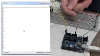
Connect your Raspberry Pi to a breadboard, download some code and create a push-button audio play project.


Puce électronique / Microchip :


Sans fil - Wireless :


Texas instrument :


Ordinateurs :


Logiciels :


Tutoriels :


Autres documentations :
![[TXT]](http://www.audentia-gestion.fr/icons/text.gif)
Analog-Devices-ADC-S..> 09-Sep-2014 08:21 2.4M
Analog-Devices-ADMC2..> 09-Sep-2014 08:21 2.4M
Analog-Devices-ADMC4..> 09-Sep-2014 08:23 2.3M
Analog-Devices-AN300..> 08-Sep-2014 17:42 2.0M
Analog-Devices-ANF32..> 09-Sep-2014 08:18 2.6M
Analog-Devices-Basic..> 08-Sep-2014 17:49 1.9M
Analog-Devices-Compl..> 08-Sep-2014 17:38 2.0M
Analog-Devices-Convo..> 09-Sep-2014 08:26 2.1M
Analog-Devices-Convo..> 09-Sep-2014 08:25 2.2M
Analog-Devices-Convo..> 09-Sep-2014 08:25 2.2M
Analog-Devices-Digit..> 08-Sep-2014 18:02 2.1M
Analog-Devices-Digit..> 08-Sep-2014 18:03 2.0M
Analog-Devices-Gloss..> 08-Sep-2014 17:36 2.0M
Analog-Devices-Intro..> 08-Sep-2014 17:39 1.9M
Analog-Devices-The-C..> 08-Sep-2014 17:41 1.9M
Analog-Devices-Visua..> 09-Sep-2014 08:18 2.5M
Analog-Devices-Wi-Fi..> 09-Sep-2014 08:23 2.3M
Electronique-Basic-o..> 08-Sep-2014 17:43 1.8M
Farnell-0050375063-D..> 18-Jul-2014 17:03 2.5M
Farnell-03-iec-runds..> 04-Jul-2014 10:40 3.7M
Farnell-0430300011-D..> 14-Jun-2014 18:13 2.0M
Farnell-0433751001-D..> 18-Jul-2014 17:02 2.5M
Farnell-06-6544-8-PD..> 26-Mar-2014 17:56 2.7M
Farnell-1N4148WS-Fai..> 06-Jul-2014 10:04 1.9M
Farnell-2-GBPS-Diffe..> 28-Jul-2014 17:42 2.7M
Farnell-2N3906-Fairc..> 08-Sep-2014 07:22 2.1M
Farnell-2N7002DW-Fai..> 06-Jul-2014 10:03 886K
Farnell-3M-Polyimide..> 21-Mar-2014 08:09 3.9M
Farnell-3M-VolitionT..> 25-Mar-2014 08:18 3.3M
Farnell-4-Bit-Magnit..> 08-Jul-2014 18:53 2.2M
Farnell-10BQ060-PDF.htm 14-Jun-2014 09:50 2.4M
Farnell-10TPB47M-End..> 14-Jun-2014 18:16 3.4M
Farnell-12mm-Size-In..> 14-Jun-2014 09:50 2.4M
Farnell-24AA024-24LC..> 23-Jun-2014 10:26 3.1M
Farnell-50A-High-Pow..> 20-Mar-2014 17:31 2.9M
Farnell-74AC00-74ACT..> 06-Jul-2014 10:03 911K
Farnell-74LCX573-Fai..> 06-Jul-2014 10:05 1.9M
Farnell-197.31-KB-Te..> 04-Jul-2014 10:42 3.3M
Farnell-270-Series-O..> 08-Jul-2014 18:49 2.3M
Farnell-760G-French-..> 07-Jul-2014 19:45 1.2M
Farnell-851-Series-P..> 08-Jul-2014 18:47 3.0M
Farnell-900-Series-B..> 08-Jul-2014 18:50 2.3M
Farnell-1734-ARALDIT..> 07-Jul-2014 19:45 1.2M
Farnell-1907-2006-PD..> 26-Mar-2014 17:56 2.7M
Farnell-2020-Manuel-..> 08-Jul-2014 18:55 2.1M
Farnell-3367-ARALDIT..> 07-Jul-2014 19:46 1.2M
Farnell-5910-PDF.htm 25-Mar-2014 08:15 3.0M
Farnell-6517b-Electr..> 29-Mar-2014 11:12 3.3M
Farnell-43031-0002-M..> 18-Jul-2014 17:03 2.5M
Farnell-A-4-Hardener..> 07-Jul-2014 19:44 1.4M
Farnell-A-True-Syste..> 29-Mar-2014 11:13 3.3M
Farnell-AC-DC-Power-..> 15-Jul-2014 16:47 845K
Farnell-ACC-Silicone..> 04-Jul-2014 10:40 3.7M
Farnell-AD524-PDF.htm 20-Mar-2014 17:33 2.8M
Farnell-AD584-Rev-C-..> 08-Sep-2014 07:20 2.2M
Farnell-AD586BRZ-Ana..> 08-Sep-2014 08:09 1.6M
Farnell-AD620-Rev-H-..> 09-Sep-2014 08:13 2.6M
Farnell-AD736-Rev-I-..> 08-Sep-2014 07:31 1.3M
Farnell-AD7171-16-Bi..> 06-Jul-2014 10:06 1.0M
Farnell-AD7719-Low-V..> 18-Jul-2014 16:59 1.4M
Farnell-AD8300-Data-..> 18-Jul-2014 16:56 1.3M
Farnell-AD8307-Data-..> 08-Sep-2014 07:30 1.3M
Farnell-AD8310-Analo..> 08-Sep-2014 07:24 2.1M
Farnell-AD8313-Analo..> 08-Sep-2014 07:26 2.0M
Farnell-AD8361-Rev-D..> 08-Sep-2014 07:23 2.1M
Farnell-AD9833-Rev-E..> 08-Sep-2014 17:49 1.8M
Farnell-AD9834-Rev-D..> 08-Sep-2014 07:32 1.2M
Farnell-ADE7753-Rev-..> 08-Sep-2014 07:20 2.3M
Farnell-ADE7758-Rev-..> 08-Sep-2014 07:28 1.7M
Farnell-ADL6507-PDF.htm 14-Jun-2014 18:19 3.4M
Farnell-ADSP-21362-A..> 20-Mar-2014 17:34 2.8M
Farnell-ADuM1200-ADu..> 08-Sep-2014 08:09 1.6M
Farnell-ADuM1300-ADu..> 08-Sep-2014 08:11 1.7M
Farnell-ALF1210-PDF.htm 06-Jul-2014 10:06 4.0M
Farnell-ALF1225-12-V..> 01-Apr-2014 07:40 3.4M
Farnell-ALF2412-24-V..> 01-Apr-2014 07:39 3.4M
Farnell-AN10361-Phil..> 23-Jun-2014 10:29 2.1M
Farnell-ARADUR-HY-13..> 26-Mar-2014 17:55 2.8M
Farnell-ARALDITE-201..> 21-Mar-2014 08:12 3.7M
Farnell-ARALDITE-CW-..> 26-Mar-2014 17:56 2.7M
Farnell-AT89C5131-Ha..> 29-Jul-2014 10:31 1.2M
Farnell-AT90USBKey-H..> 29-Jul-2014 10:31 902K
Farnell-ATMEL-8-bit-..> 19-Mar-2014 18:04 2.1M
Farnell-ATMEL-8-bit-..> 11-Mar-2014 07:55 2.1M
Farnell-ATmega640-VA..> 14-Jun-2014 09:49 2.5M
Farnell-ATtiny20-PDF..> 25-Mar-2014 08:19 3.6M
Farnell-ATtiny26-L-A..> 18-Jul-2014 17:00 2.6M
Farnell-ATtiny26-L-A..> 13-Jun-2014 18:40 1.8M
Farnell-Alimentation..> 07-Jul-2014 19:43 1.8M
Farnell-Alimentation..> 14-Jun-2014 18:24 2.5M
Farnell-Alimentation..> 01-Apr-2014 07:42 3.4M
Farnell-Amplificateu..> 29-Mar-2014 11:11 3.3M
Farnell-Amplifier-In..> 06-Jul-2014 10:02 940K
Farnell-An-Improved-..> 14-Jun-2014 09:49 2.5M
Farnell-Araldite-Fus..> 07-Jul-2014 19:45 1.2M
Farnell-Arithmetic-L..> 08-Jul-2014 18:54 2.1M
Farnell-Atmel-ATmega..> 19-Mar-2014 18:03 2.2M
Farnell-Avvertenze-e..> 14-Jun-2014 18:20 3.3M
Farnell-BA-Series-Oh..> 08-Jul-2014 18:50 2.3M
Farnell-BAV99-Fairch..> 06-Jul-2014 10:03 896K
Farnell-BC846DS-NXP-..> 13-Jun-2014 18:42 1.6M
Farnell-BC847DS-NXP-..> 23-Jun-2014 10:24 3.3M
Farnell-BD6xxx-PDF.htm 22-Jul-2014 12:33 1.6M
Farnell-BF545A-BF545..> 23-Jun-2014 10:28 2.1M
Farnell-BGA7124-400-..> 18-Jul-2014 16:59 1.5M
Farnell-BK889B-PONT-..> 07-Jul-2014 19:42 1.8M
Farnell-BK2650A-BK26..> 29-Mar-2014 11:10 3.3M
Farnell-BT151-650R-N..> 13-Jun-2014 18:40 1.7M
Farnell-BTA204-800C-..> 13-Jun-2014 18:42 1.6M
Farnell-BUJD203AX-NX..> 13-Jun-2014 18:41 1.7M
Farnell-BYV29F-600-N..> 13-Jun-2014 18:42 1.6M
Farnell-BYV79E-serie..> 10-Mar-2014 16:19 1.6M
Farnell-BZX384-serie..> 23-Jun-2014 10:29 2.1M
Farnell-Battery-GBA-..> 14-Jun-2014 18:13 2.0M
Farnell-Both-the-Del..> 06-Jul-2014 10:01 948K
Farnell-C.A-6150-C.A..> 14-Jun-2014 18:24 2.5M
Farnell-C.A 8332B-C...> 01-Apr-2014 07:40 3.4M
Farnell-CC-Debugger-..> 07-Jul-2014 19:44 1.5M
Farnell-CC2530ZDK-Us..> 08-Jul-2014 18:55 2.1M
Farnell-CC2531-USB-H..> 07-Jul-2014 19:43 1.8M
Farnell-CC2560-Bluet..> 29-Mar-2014 11:14 2.8M
Farnell-CD4536B-Type..> 14-Jun-2014 18:13 2.0M
Farnell-CIRRUS-LOGIC..> 10-Mar-2014 17:20 2.1M
Farnell-CLASS 1-or-2..> 22-Jul-2014 12:30 4.7M
Farnell-CRC-HANDCLEA..> 07-Jul-2014 19:46 1.2M
Farnell-CS5532-34-BS..> 01-Apr-2014 07:39 3.5M
Farnell-Cannon-ZD-PD..> 11-Mar-2014 08:13 2.8M
Farnell-Ceramic-tran..> 14-Jun-2014 18:19 3.4M
Farnell-Circuit-Impr..> 25-Jul-2014 12:22 3.1M
Farnell-Circuit-Note..> 26-Mar-2014 18:00 2.8M
Farnell-Circuit-Note..> 26-Mar-2014 18:00 2.8M
Farnell-Cles-electro..> 21-Mar-2014 08:13 3.9M
Farnell-Clipper-Seri..> 08-Jul-2014 18:48 2.8M
Farnell-Compensating..> 09-Sep-2014 08:16 2.6M
Farnell-Compensating..> 09-Sep-2014 08:16 2.6M
Farnell-Conception-d..> 11-Mar-2014 07:49 2.4M
Farnell-Connectors-N..> 14-Jun-2014 18:12 2.1M
Farnell-Construction..> 14-Jun-2014 18:25 2.5M
Farnell-Controle-de-..> 11-Mar-2014 08:16 2.8M
Farnell-Cordless-dri..> 14-Jun-2014 18:13 2.0M
Farnell-Cube-3D-Prin..> 18-Jul-2014 17:02 2.5M
Farnell-Current-Tran..> 26-Mar-2014 17:58 2.7M
Farnell-Current-Tran..> 26-Mar-2014 17:58 2.7M
Farnell-Current-Tran..> 26-Mar-2014 17:59 2.7M
Farnell-Current-Tran..> 26-Mar-2014 17:59 2.7M
Farnell-DAC8143-Data..> 18-Jul-2014 16:59 1.5M
Farnell-DC-DC-Conver..> 15-Jul-2014 16:48 781K
Farnell-DC-Fan-type-..> 14-Jun-2014 09:48 2.5M
Farnell-DC-Fan-type-..> 14-Jun-2014 09:51 1.8M
Farnell-DG411-DG412-..> 07-Jul-2014 19:47 1.0M
Farnell-DP83846A-DsP..> 18-Jul-2014 16:55 1.5M
Farnell-DS3231-DS-PD..> 18-Jul-2014 16:57 2.5M
Farnell-Data-Sheet-K..> 07-Jul-2014 19:46 1.2M
Farnell-Data-Sheet-M..> 09-Sep-2014 08:05 2.8M
Farnell-Data-Sheet-S..> 18-Jul-2014 17:00 1.2M
Farnell-Datasheet-FT..> 09-Sep-2014 08:10 2.8M
Farnell-Datasheet-Fa..> 06-Jul-2014 10:04 861K
Farnell-Datasheet-Fa..> 15-Jul-2014 17:05 1.0M
Farnell-Datasheet-NX..> 15-Jul-2014 17:06 1.0M
Farnell-Davum-TMC-PD..> 14-Jun-2014 18:27 2.4M
Farnell-De-la-puissa..> 29-Mar-2014 11:10 3.3M
Farnell-Decapant-KF-..> 07-Jul-2014 19:45 1.2M
Farnell-Directive-re..> 25-Mar-2014 08:16 3.0M
Farnell-Documentatio..> 14-Jun-2014 18:26 2.5M
Farnell-Download-dat..> 16-Jul-2014 09:02 2.2M
Farnell-Download-dat..> 13-Jun-2014 18:40 1.8M
Farnell-Dremel-Exper..> 22-Jul-2014 12:34 1.6M
Farnell-Dual-MOSFET-..> 28-Jul-2014 17:41 2.8M
Farnell-ECO-Series-T..> 20-Mar-2014 08:14 2.5M
Farnell-EE-SPX303N-4..> 15-Jul-2014 17:06 969K
Farnell-ELMA-PDF.htm 29-Mar-2014 11:13 3.3M
Farnell-EMC1182-PDF.htm 25-Mar-2014 08:17 3.0M
Farnell-EPCOS-173438..> 04-Jul-2014 10:43 3.3M
Farnell-EPCOS-Sample..> 11-Mar-2014 07:53 2.2M
Farnell-ES1F-ES1J-fi..> 06-Jul-2014 10:04 867K
Farnell-ES2333-PDF.htm 11-Mar-2014 08:14 2.8M
Farnell-ESCON-Featur..> 06-Jul-2014 10:05 938K
Farnell-ESCON-Featur..> 06-Jul-2014 10:02 931K
Farnell-Ed.081002-DA..> 19-Mar-2014 18:02 2.5M
Farnell-Encodeur-USB..> 08-Jul-2014 18:56 2.0M
Farnell-Evaluating-t..> 22-Jul-2014 12:28 4.9M
Farnell-Everything-Y..> 11-Oct-2014 12:05 1.5M
Farnell-Excalibur-Hi..> 28-Jul-2014 17:10 2.4M
Farnell-Excalibur-Hi..> 28-Jul-2014 17:10 2.4M
Farnell-Explorer-16-..> 29-Jul-2014 10:31 1.3M
Farnell-F28069-Picco..> 14-Jun-2014 18:14 2.0M
Farnell-F42202-PDF.htm 19-Mar-2014 18:00 2.5M
Farnell-FAN6756-Fair..> 06-Jul-2014 10:04 850K
Farnell-FDC2512-Fair..> 06-Jul-2014 10:03 886K
Farnell-FDS-ITW-Spra..> 14-Jun-2014 18:22 3.3M
Farnell-FDV301N-Digi..> 06-Jul-2014 10:03 886K
Farnell-FICHE-DE-DON..> 10-Mar-2014 16:17 1.6M
Farnell-Fast-Charge-..> 28-Jul-2014 17:12 6.4M
Farnell-Fastrack-Sup..> 23-Jun-2014 10:25 3.3M
Farnell-Ferric-Chlor..> 29-Mar-2014 11:14 2.8M
Farnell-Fiche-de-don..> 14-Jun-2014 09:47 2.5M
Farnell-Fiche-de-don..> 14-Jun-2014 18:26 2.5M
Farnell-Fluke-1730-E..> 14-Jun-2014 18:23 2.5M
Farnell-Full-Datashe..> 15-Jul-2014 17:08 951K
Farnell-Full-Datashe..> 15-Jul-2014 16:47 803K
Farnell-GALVA-A-FROI..> 26-Mar-2014 17:56 2.7M
Farnell-GALVA-MAT-Re..> 26-Mar-2014 17:57 2.7M
Farnell-GN-RELAYS-AG..> 20-Mar-2014 08:11 2.6M
Farnell-Gertboard-Us..> 29-Jul-2014 10:30 1.4M
Farnell-HC49-4H-Crys..> 14-Jun-2014 18:20 3.3M
Farnell-HFE1600-Data..> 14-Jun-2014 18:22 3.3M
Farnell-HI-70300-Sol..> 14-Jun-2014 18:27 2.4M
Farnell-HIP4081A-Int..> 07-Jul-2014 19:47 1.0M
Farnell-HUNTSMAN-Adv..> 10-Mar-2014 16:17 1.7M
Farnell-Haute-vitess..> 11-Mar-2014 08:17 2.4M
Farnell-Hex-Inverter..> 29-Jul-2014 10:31 875K
Farnell-High-precisi..> 08-Jul-2014 18:51 2.3M
Farnell-ICM7228-Inte..> 07-Jul-2014 19:46 1.1M
Farnell-IP4252CZ16-8..> 13-Jun-2014 18:41 1.7M
Farnell-ISL6251-ISL6..> 07-Jul-2014 19:47 1.1M
Farnell-Instructions..> 19-Mar-2014 18:01 2.5M
Farnell-Jeu-multi-la..> 25-Jul-2014 12:23 3.0M
Farnell-KSZ8851SNL-S..> 23-Jun-2014 10:28 2.1M
Farnell-Keyboard-Mou..> 22-Jul-2014 12:27 5.9M
Farnell-L-efficacite..> 11-Mar-2014 07:52 2.3M
Farnell-L78S-STMicro..> 22-Jul-2014 12:32 1.6M
Farnell-L293d-Texas-..> 08-Jul-2014 18:53 2.2M
Farnell-LCW-CQ7P.CC-..> 25-Mar-2014 08:19 3.2M
Farnell-LD-WSECO16-P..> 25-Jul-2014 12:22 3.1M
Farnell-LM3S6952-Mic..> 22-Jul-2014 12:27 5.9M
Farnell-LM19-Texas-I..> 18-Jul-2014 17:00 1.2M
Farnell-LM324-Texas-..> 29-Jul-2014 10:32 1.5M
Farnell-LM386-Low-Vo..> 29-Jul-2014 10:32 1.5M
Farnell-LM555-Timer-..> 08-Jul-2014 18:53 2.2M
Farnell-LM7805-Fairc..> 09-Sep-2014 08:13 2.7M
Farnell-LME49725-Pow..> 14-Jun-2014 09:49 2.5M
Farnell-LMH6518-Texa..> 18-Jul-2014 16:59 1.3M
Farnell-LMP91051-Use..> 29-Jul-2014 10:30 1.4M
Farnell-LMT88-2.4V-1..> 28-Jul-2014 17:42 2.8M
Farnell-LOCTITE-542-..> 25-Mar-2014 08:15 3.0M
Farnell-LOCTITE-3463..> 25-Mar-2014 08:19 3.0M
Farnell-LPC11U3x-32-..> 16-Jul-2014 09:01 2.4M
Farnell-LPC81xM-32-b..> 16-Jul-2014 09:02 2.0M
Farnell-LPC408x-7x 3..> 16-Jul-2014 09:03 1.6M
Farnell-LPC1769-68-6..> 16-Jul-2014 09:02 1.9M
Farnell-LPC3220-30-4..> 16-Jul-2014 09:02 2.2M
Farnell-LQ-RELAYS-AL..> 06-Jul-2014 10:02 924K
Farnell-LT1961-Linea..> 18-Jul-2014 16:58 1.6M
Farnell-LT3757-Linea..> 18-Jul-2014 16:58 1.6M
Farnell-LT6233-Linea..> 18-Jul-2014 16:56 1.3M
Farnell-LUMINARY-MIC..> 22-Jul-2014 12:31 3.6M
Farnell-LUXEON-Guide..> 11-Mar-2014 07:52 2.3M
Farnell-Leaded-Trans..> 23-Jun-2014 10:26 3.2M
Farnell-Les-derniers..> 11-Mar-2014 07:50 2.3M
Farnell-Loctite3455-..> 25-Mar-2014 08:16 3.0M
Farnell-Low-Noise-24..> 06-Jul-2014 10:05 1.0M
Farnell-Low-cost-Enc..> 13-Jun-2014 18:42 1.7M
Farnell-Lubrifiant-a..> 26-Mar-2014 18:00 2.7M
Farnell-MAX232-MAX23..> 08-Jul-2014 18:52 2.3M
Farnell-MAX1365-MAX1..> 18-Jul-2014 16:56 1.4M
Farnell-MAX3221-Rev-..> 08-Sep-2014 07:28 1.8M
Farnell-MAX4661-MAX4..> 09-Sep-2014 08:10 2.8M
Farnell-MC3510-PDF.htm 25-Mar-2014 08:17 3.0M
Farnell-MC21605-PDF.htm 11-Mar-2014 08:14 2.8M
Farnell-MCF532x-7x-E..> 29-Mar-2014 11:14 2.8M
Farnell-MCOC1-Farnel..> 16-Jul-2014 09:04 1.0M
Farnell-MCP3421-Micr..> 18-Jul-2014 17:00 1.2M
Farnell-MICREL-KSZ88..> 11-Mar-2014 07:54 2.2M
Farnell-MICROCHIP-PI..> 19-Mar-2014 18:02 2.5M
Farnell-MICROCHIP-PI..> 25-Jul-2014 12:34 6.7M
Farnell-MIDAS-un-tra..> 15-Jul-2014 17:05 1.0M
Farnell-MOLEX-39-00-..> 10-Mar-2014 17:19 1.9M
Farnell-MOLEX-43020-..> 10-Mar-2014 17:21 1.9M
Farnell-MOLEX-43160-..> 10-Mar-2014 17:21 1.9M
Farnell-MOLEX-87439-..> 10-Mar-2014 17:21 1.9M
Farnell-MPXV7002-Rev..> 20-Mar-2014 17:33 2.8M
Farnell-MSP-EXP430F5..> 29-Jul-2014 10:31 1.2M
Farnell-MSP430-Hardw..> 29-Jul-2014 10:36 1.1M
Farnell-MSP430F15x-M..> 08-Sep-2014 07:32 1.3M
Farnell-MTX-3250-MTX..> 18-Jul-2014 17:01 2.5M
Farnell-MTX-Compact-..> 18-Jul-2014 17:01 2.5M
Farnell-MULTICOMP-Ra..> 22-Jul-2014 12:57 5.9M
Farnell-MX670-MX675-..> 14-Jun-2014 09:46 2.5M
Farnell-Microchip-MC..> 13-Jun-2014 18:27 1.8M
Farnell-Microship-PI..> 11-Mar-2014 07:53 2.2M
Farnell-Midas-Active..> 14-Jun-2014 18:17 3.4M
Farnell-Midas-MCCOG4..> 14-Jun-2014 18:11 2.1M
Farnell-Mini-Fit-Jr-..> 18-Jul-2014 17:03 2.5M
Farnell-Miniature-Ci..> 26-Mar-2014 17:55 2.8M
Farnell-Mistral-PDF.htm 14-Jun-2014 18:12 2.1M
Farnell-Molex-83421-..> 14-Jun-2014 18:17 3.4M
Farnell-Molex-COMMER..> 14-Jun-2014 18:16 3.4M
Farnell-Molex-Crimp-..> 10-Mar-2014 16:27 1.7M
Farnell-Multi-Functi..> 20-Mar-2014 17:38 3.0M
Farnell-NA555-NE555-..> 08-Jul-2014 18:53 2.2M
Farnell-NA555-NE555-..> 08-Sep-2014 07:51 1.5M
Farnell-NE5532-Texas..> 29-Jul-2014 10:32 1.5M
Farnell-NTE_SEMICOND..> 11-Mar-2014 07:52 2.3M
Farnell-NVE-datashee..> 28-Jul-2014 17:12 6.5M
Farnell-NXP-74VHC126..> 10-Mar-2014 16:17 1.6M
Farnell-NXP-BT136-60..> 11-Mar-2014 07:52 2.3M
Farnell-NXP-PBSS9110..> 10-Mar-2014 17:21 1.9M
Farnell-NXP-PCA9555 ..> 11-Mar-2014 07:54 2.2M
Farnell-NXP-PMBFJ620..> 10-Mar-2014 16:16 1.7M
Farnell-NXP-PSMN1R7-..> 10-Mar-2014 16:17 1.6M
Farnell-NXP-PSMN7R0-..> 10-Mar-2014 17:19 2.1M
Farnell-NXP-TEA1703T..> 11-Mar-2014 08:15 2.8M
Farnell-NaPiOn-Panas..> 06-Jul-2014 10:02 911K
Farnell-Nilï¬-sk-E-..> 14-Jun-2014 09:47 2.5M
Farnell-Novembre-201..> 20-Mar-2014 17:38 3.3M
Farnell-OMRON-INDUST..> 25-Jul-2014 12:31 6.9M
Farnell-OMRON-INDUST..> 25-Jul-2014 12:32 6.9M
Farnell-OMRON-Master..> 10-Mar-2014 16:26 1.8M
Farnell-OPA627-Texas..> 09-Sep-2014 08:08 2.8M
Farnell-OSLON-SSL-Ce..> 19-Mar-2014 18:03 2.1M
Farnell-OXPCIE958-FB..> 13-Jun-2014 18:40 1.8M
Farnell-Octal-Genera..> 28-Jul-2014 17:42 2.8M
Farnell-PADO-semi-au..> 04-Jul-2014 10:41 3.7M
Farnell-PBSS5160T-60..> 19-Mar-2014 18:03 2.1M
Farnell-PCF8574-PCF8..> 16-Jul-2014 09:03 1.7M
Farnell-PDTA143X-ser..> 20-Mar-2014 08:12 2.6M
Farnell-PDTB123TT-NX..> 13-Jun-2014 18:43 1.5M
Farnell-PESD5V0F1BL-..> 13-Jun-2014 18:43 1.5M
Farnell-PESD9X5.0L-P..> 13-Jun-2014 18:43 1.6M
Farnell-PIC12F609-61..> 04-Jul-2014 10:41 3.7M
Farnell-PIC18F2420-2..> 18-Jul-2014 16:57 2.5M
Farnell-PIC18F2455-2..> 23-Jun-2014 10:27 3.1M
Farnell-PIC24FJ256GB..> 14-Jun-2014 09:51 2.4M
Farnell-PMBT3906-PNP..> 13-Jun-2014 18:44 1.5M
Farnell-PMBT4403-PNP..> 23-Jun-2014 10:27 3.1M
Farnell-PMEG4002EL-N..> 14-Jun-2014 18:18 3.4M
Farnell-PMEG4010CEH-..> 13-Jun-2014 18:43 1.6M
Farnell-PN512-Full-N..> 16-Jul-2014 09:03 1.4M
Farnell-Panasonic-15..> 23-Jun-2014 10:29 2.1M
Farnell-Panasonic-EC..> 20-Mar-2014 17:36 2.6M
Farnell-Panasonic-EZ..> 20-Mar-2014 08:10 2.6M
Farnell-Panasonic-Id..> 20-Mar-2014 17:35 2.6M
Farnell-Panasonic-Ne..> 20-Mar-2014 17:36 2.6M
Farnell-Panasonic-Ra..> 20-Mar-2014 17:37 2.6M
Farnell-Panasonic-TS..> 20-Mar-2014 08:12 2.6M
Farnell-Panasonic-Y3..> 20-Mar-2014 08:11 2.6M
Farnell-PiFace-Digit..> 25-Jul-2014 12:25 3.0M
Farnell-Pico-Spox-Wi..> 10-Mar-2014 16:16 1.7M
Farnell-PicoScope-42..> 25-Jul-2014 12:23 3.0M
Farnell-PicoScope-se..> 25-Jul-2014 12:24 3.0M
Farnell-Pompes-Charg..> 24-Apr-2014 20:23 3.3M
Farnell-Ponts-RLC-po..> 14-Jun-2014 18:23 3.3M
Farnell-Portable-Ana..> 29-Mar-2014 11:16 2.8M
Farnell-Power-suppli..> 25-Jul-2014 12:29 7.0M
Farnell-Premier-Farn..> 21-Mar-2014 08:11 3.8M
Farnell-Produit-3430..> 14-Jun-2014 09:48 2.5M
Farnell-Proskit-SS-3..> 10-Mar-2014 16:26 1.8M
Farnell-Puissance-ut..> 11-Mar-2014 07:49 2.4M
Farnell-Q48-PDF.htm 23-Jun-2014 10:29 2.1M
Farnell-QRE1113-Fair..> 06-Jul-2014 10:03 879K
Farnell-Quadruple-2-..> 08-Sep-2014 07:29 1.5M
Farnell-Quick-Start-..> 25-Jul-2014 12:25 3.0M
Farnell-RASPBERRY-PI..> 22-Jul-2014 12:35 5.9M
Farnell-RDS-80-PDF.htm 18-Jul-2014 16:57 1.3M
Farnell-REF19x-Serie..> 09-Sep-2014 08:08 2.8M
Farnell-REF102-10V-P..> 28-Jul-2014 17:09 2.4M
Farnell-RF-short-tra..> 28-Jul-2014 17:16 6.3M
Farnell-Radial-Lead-..> 20-Mar-2014 08:12 2.6M
Farnell-RaspiCam-Doc..> 22-Jul-2014 12:32 1.6M
Farnell-Realiser-un-..> 11-Mar-2014 07:51 2.3M
Farnell-Reglement-RE..> 21-Mar-2014 08:08 3.9M
Farnell-Repartiteurs..> 14-Jun-2014 18:26 2.5M
Farnell-S-TRI-SWT860..> 21-Mar-2014 08:11 3.8M
Farnell-S1A-Fairchil..> 06-Jul-2014 10:03 896K
Farnell-SB175-Connec..> 11-Mar-2014 08:14 2.8M
Farnell-SB520-SB5100..> 22-Jul-2014 12:32 1.6M
Farnell-SERIAL-TFT-M..> 15-Jul-2014 17:05 1.0M
Farnell-SICK-OPTIC-E..> 18-Jul-2014 16:58 1.5M
Farnell-SL3ICS1002-1..> 16-Jul-2014 09:05 2.5M
Farnell-SL3S1203_121..> 16-Jul-2014 09:04 1.1M
Farnell-SL3S4011_402..> 16-Jul-2014 09:03 1.1M
Farnell-SL59830-Inte..> 06-Jul-2014 10:11 1.0M
Farnell-SMBJ-Transil..> 29-Mar-2014 11:12 3.3M
Farnell-SMU-Instrume..> 08-Jul-2014 18:51 2.3M
Farnell-SN54HC164-SN..> 08-Sep-2014 07:25 2.0M
Farnell-SN54HC244-SN..> 08-Jul-2014 18:52 2.3M
Farnell-SN54LV4053A-..> 28-Jul-2014 17:20 5.9M
Farnell-SO967460-PDF..> 11-Oct-2014 12:05 2.9M
Farnell-SOT-23-Multi..> 11-Mar-2014 07:51 2.3M
Farnell-SOURIAU-Cont..> 08-Jul-2014 19:04 3.0M
Farnell-SPLC780A1-16..> 14-Jun-2014 18:25 2.5M
Farnell-SSC7102-Micr..> 23-Jun-2014 10:25 3.2M
Farnell-STM32F103x8-..> 22-Jul-2014 12:33 1.6M
Farnell-STM32F405xxS..> 27-Aug-2014 18:27 1.8M
Farnell-SVPE-series-..> 14-Jun-2014 18:15 2.0M
Farnell-Schroff-A108..> 25-Jul-2014 12:27 2.8M
Farnell-Schroff-Main..> 25-Jul-2014 12:26 2.9M
Farnell-Schroff-mult..> 25-Jul-2014 12:26 2.9M
Farnell-Sensorless-C..> 04-Jul-2014 10:42 3.3M
Farnell-Septembre-20..> 20-Mar-2014 17:46 3.7M
Farnell-Serial-File-..> 06-Jul-2014 10:02 941K
Farnell-Serie-PicoSc..> 19-Mar-2014 18:01 2.5M
Farnell-Serie-Standa..> 14-Jun-2014 18:23 3.3M
Farnell-Series-2600B..> 20-Mar-2014 17:30 3.0M
Farnell-Series-TDS10..> 04-Jul-2014 10:39 4.0M
Farnell-Signal-PCB-R..> 14-Jun-2014 18:11 2.1M
Farnell-Silica-Gel-M..> 07-Jul-2014 19:46 1.2M
Farnell-Single-Chip-..> 08-Sep-2014 07:30 1.5M
Farnell-SmartRF06-Ev..> 07-Jul-2014 19:43 1.6M
Farnell-Strangkuhlko..> 21-Mar-2014 08:09 3.9M
Farnell-Supercapacit..> 26-Mar-2014 17:57 2.7M
Farnell-Synchronous-..> 08-Jul-2014 18:54 2.1M
Farnell-T672-3000-Se..> 08-Jul-2014 18:59 2.0M
Farnell-TAS1020B-USB..> 28-Jul-2014 17:19 6.2M
Farnell-TCL-DC-traco..> 15-Jul-2014 16:46 858K
Farnell-TDK-Lambda-H..> 14-Jun-2014 18:21 3.3M
Farnell-TEKTRONIX-DP..> 10-Mar-2014 17:20 2.0M
Farnell-TEL-5-Series..> 15-Jul-2014 16:47 814K
Farnell-TEN-8-WI-Ser..> 15-Jul-2014 16:46 939K
Farnell-TEP-150WI-Se..> 15-Jul-2014 16:47 837K
Farnell-TEXAS-INSTRU..> 22-Jul-2014 12:29 4.8M
Farnell-TEXAS-INSTRU..> 22-Jul-2014 12:31 2.4M
Farnell-TEXAS-INSTRU..> 22-Jul-2014 12:30 4.6M
Farnell-TIS-Instruct..> 15-Jul-2014 16:47 845K
Farnell-TIS-series-t..> 15-Jul-2014 16:46 875K
Farnell-TKC2-Dusters..> 07-Jul-2014 19:46 1.2M
Farnell-TL082-Wide-B..> 28-Jul-2014 17:16 6.3M
Farnell-TLV320AIC23B..> 08-Sep-2014 07:18 2.4M
Farnell-TLV320AIC325..> 28-Jul-2014 17:45 2.9M
Farnell-TMLM-Series-..> 15-Jul-2014 16:47 810K
Farnell-TMP006EVM-Us..> 29-Jul-2014 10:30 1.3M
Farnell-TMR-2-Series..> 15-Jul-2014 16:46 897K
Farnell-TMR-2-series..> 15-Jul-2014 16:48 787K
Farnell-TMR-3-WI-Ser..> 15-Jul-2014 16:46 939K
Farnell-TMS320F28055..> 28-Jul-2014 17:09 2.7M
Farnell-TOS-tracopow..> 15-Jul-2014 16:47 852K
Farnell-TPS40060-Wid..> 28-Jul-2014 17:19 6.3M
Farnell-TSV6390-TSV6..> 28-Jul-2014 17:14 6.4M
Farnell-TXL-series-t..> 15-Jul-2014 16:47 829K
Farnell-TYCO-ELECTRO..> 25-Jul-2014 12:30 6.9M
Farnell-Tektronix-AC..> 13-Jun-2014 18:44 1.5M
Farnell-Telemetres-l..> 20-Mar-2014 17:46 3.7M
Farnell-Termometros-..> 14-Jun-2014 18:14 2.0M
Farnell-The-Discrete..> 08-Sep-2014 17:44 1.8M
Farnell-The-essentia..> 10-Mar-2014 16:27 1.7M
Farnell-Thermometre-..> 29-Jul-2014 10:30 1.4M
Farnell-Tiva-C-Serie..> 08-Jul-2014 18:49 2.6M
Farnell-Trust-Digita..> 25-Jul-2014 12:24 3.0M
Farnell-U2270B-PDF.htm 14-Jun-2014 18:15 3.4M
Farnell-ULINKpro-Deb..> 25-Jul-2014 12:35 5.9M
Farnell-ULN2803A-Rev..> 09-Sep-2014 19:26 2.9M
Farnell-USB-Buccanee..> 14-Jun-2014 09:48 2.5M
Farnell-USB-to-Seria..> 08-Sep-2014 07:27 2.0M
Farnell-USB1T11A-PDF..> 19-Mar-2014 18:03 2.1M
Farnell-UTO-Souriau-..> 08-Jul-2014 18:48 2.8M
Farnell-UTS-Series-S..> 08-Jul-2014 18:49 2.8M
Farnell-UTS-Series-S..> 08-Jul-2014 18:49 2.5M
Farnell-User-Guide-M..> 07-Jul-2014 19:41 2.0M
Farnell-V4N-PDF.htm 14-Jun-2014 18:11 2.1M
Farnell-Videk-PDF.htm 06-Jul-2014 10:01 948K
Farnell-WIRE-WRAP-50..> 25-Jul-2014 12:34 5.9M
Farnell-WetTantalum-..> 11-Mar-2014 08:14 2.8M
Farnell-XPS-AC-Octop..> 14-Jun-2014 18:11 2.1M
Farnell-XPS-MC16-XPS..> 11-Mar-2014 08:15 2.8M
Farnell-XPSAF5130-PD..> 18-Jul-2014 16:56 1.4M
Farnell-YAGEO-DATA-S..> 11-Mar-2014 08:13 2.8M
Farnell-ZigBee-ou-le..> 11-Mar-2014 07:50 2.4M
Farnell-celpac-SUL84..> 21-Mar-2014 08:11 3.8M
Farnell-china_rohs_o..> 21-Mar-2014 10:04 3.9M
Farnell-cree-Xlamp-X..> 20-Mar-2014 17:34 2.8M
Farnell-cree-Xlamp-X..> 20-Mar-2014 17:35 2.7M
Farnell-cree-Xlamp-X..> 20-Mar-2014 17:31 2.9M
Farnell-cree-Xlamp-m..> 20-Mar-2014 17:32 2.9M
Farnell-cree-Xlamp-m..> 20-Mar-2014 17:32 2.9M
Farnell-ev-relays-ae..> 06-Jul-2014 10:02 926K
Farnell-fiche-de-don..> 07-Jul-2014 19:44 1.4M
Farnell-fx-3650P-fx-..> 29-Jul-2014 10:42 1.5M
Farnell-iServer-Micr..> 22-Jul-2014 12:32 1.6M
Farnell-ir1150s_fr.p..> 29-Mar-2014 11:11 3.3M
Farnell-manual-bus-p..> 10-Mar-2014 16:29 1.9M
Farnell-maxim-integr..> 28-Jul-2014 17:14 6.4M
Farnell-pmbta13_pmbt..> 15-Jul-2014 17:06 959K
Farnell-propose-plus..> 11-Mar-2014 08:19 2.8M
Farnell-safety-data-..> 07-Jul-2014 19:44 1.4M
Farnell-techfirst_se..> 21-Mar-2014 08:08 3.9M
Farnell-tesa®pack63..> 08-Jul-2014 18:56 2.0M
Farnell-testo-205-20..> 20-Mar-2014 17:37 3.0M
Farnell-testo-470-Fo..> 20-Mar-2014 17:38 3.0M
Farnell-uC-OS-III-Br..> 10-Mar-2014 17:20 2.0M
Farnell-user-manuel-..> 29-Jul-2014 10:29 1.5M
Sefram-7866HD.pdf-PD..> 29-Mar-2014 11:46 472K
Sefram-CAT_ENREGISTR..> 29-Mar-2014 11:46 461K
Sefram-CAT_MESUREURS..> 29-Mar-2014 11:46 435K
Sefram-GUIDE_SIMPLIF..> 29-Mar-2014 11:46 481K
Sefram-GUIDE_SIMPLIF..> 29-Mar-2014 11:46 442K
Sefram-GUIDE_SIMPLIF..> 29-Mar-2014 11:46 422K
Sefram-SP270.pdf-PDF..> 29-Mar-2014 11:46 464K
Farnell-AN2794-Appli..> 13-Oct-2014 10:02 1.0M
Farnell-Data-Sheet-S..> 13-Oct-2014 10:09 1.2M
Farnell-ESM6045DV-ST..> 13-Oct-2014 10:07 850K
Farnell-L78-Positive..> 13-Oct-2014 10:05 1.8M
Farnell-L78S-STMicro..> 13-Oct-2014 10:09 1.6M
Farnell-L4978-STMicr..> 13-Oct-2014 10:08 783K
Farnell-L6384E-STMic..> 13-Oct-2014 10:03 1.9M
Farnell-L6562-STMicr..> 13-Oct-2014 10:08 754K
Farnell-LM139-LM239-..> 13-Oct-2014 10:08 771K
Farnell-LM217-LM317-..> 13-Oct-2014 10:05 1.7M
Farnell-LM350-STMicr..> 13-Oct-2014 10:04 1.8M
Farnell-LM2904-LM290..> 13-Oct-2014 10:05 1.7M
Farnell-MC34063ABD-T..> 13-Oct-2014 10:07 844K
Farnell-SG2525A-SG35..> 13-Oct-2014 10:02 1.0M
Farnell-SMAJ-STMicro..> 13-Oct-2014 10:08 734K
Farnell-ST1S10PHR-ST..> 13-Oct-2014 10:08 820K
Farnell-ST3232B-ST32..> 13-Oct-2014 10:07 867K
Farnell-STEVAL-TDR02..> 13-Oct-2014 10:02 960K
Farnell-STM32F030x4-..> 13-Oct-2014 10:07 1.1M
Farnell-STM32F103x8-..> 13-Oct-2014 10:07 1.0M
Farnell-STM32F205xx-..> 13-Oct-2014 10:06 1.7M
Farnell-STM32F405xx-..> 13-Oct-2014 10:06 1.4M
Farnell-STP16NF06L-n..> 13-Oct-2014 10:06 1.7M
Farnell-STP80NF55L-0..> 13-Oct-2014 10:06 1.7M
Farnell-Smart-street..> 13-Oct-2014 10:04 1.8M
Farnell-TIP41C-TIP42..> 13-Oct-2014 10:08 829K
Farnell-TIP102-TIP10..> 13-Oct-2014 10:07 853K
Farnell-TSV6390-TSV6..> 13-Oct-2014 10:10 6.4M
Farnell-ULN2001-ULN2..> 13-Oct-2014 10:03 1.9M
Farnell-ULQ2001-ULQ2..> 13-Oct-2014 10:03 1.9M
Farnell-VND920P-E-ST..> 13-Oct-2014 10:04 1.8M
1. Product profile
1.1 General description
Planar Schottky barrier single diode with an integrated guard ring for stress protection,
encapsulated in a SOD323F (SC-90) very small and flat lead Surface-Mounted Device
(SMD) plastic package.
1.2 Features
■ Low forward voltage
■ Very small and flat lead SMD plastic package
■ Low capacitance
■ Flat leads: excellent coplanarity and improved thermal behavior
1.3 Applications
■ Voltage clamping
■ Line termination
■ Reverse polarity protection
1.4 Quick reference data
[1] Pulse test: tp ≤ 300 µs; δ ≤ 0.02.
BAT54J
Schottky barrier single diode
Rev. 01 — 8 March 2007 Product data sheet
Table 1. Quick reference data
Symbol Parameter Conditions Min Typ Max Unit
IF forward current - - 200 mA
VR reverse voltage - - 30 V
VF forward voltage IF = 1 mA [1] - - 320 mVBAT54J_1 © NXP B.V. 2007. All rights reserved.
Product data sheet Rev. 01 — 8 March 2007 2 of 8
NXP Semiconductors BAT54J
Schottky barrier single diode
2. Pinning information
[1] The marking bar indicates the cathode.
3. Ordering information
4. Marking
5. Limiting values
[1] Device mounted on an FR4 Printed-Circuit Board (PCB), single-sided copper, tin-plated, mounting pad for
cathode 1 cm2.
Table 2. Pinning
Pin Description Simplified outline Symbol
1 cathode [1]
2 anode 1 2
sym001
1 2
Table 3. Ordering information
Type number Package
Name Description Version
BAT54J SC-90 plastic surface-mounted package; 2 leads SOD323F
Table 4. Marking codes
Type number Marking code
BAT54J AP
Table 5. Limiting values
In accordance with the Absolute Maximum Rating System (IEC 60134).
Symbol Parameter Conditions Min Max Unit
VR reverse voltage - 30 V
IF forward current - 200 mA
IFRM repetitive peak forward
current
tp ≤ 1 s; δ ≤ 0.5 - 300 mA
IFSM non-repetitive peak forward
current
square wave;
tp < 10 ms
- 600 mA
Ptot total power dissipation Tamb ≤ 25 °C [1] - 550 mW
Tj junction temperature - 150 °C
Tamb ambient temperature −65 +150 °C
Tstg storage temperature −65 +150 °CBAT54J_1 © NXP B.V. 2007. All rights reserved.
Product data sheet Rev. 01 — 8 March 2007 3 of 8
NXP Semiconductors BAT54J
Schottky barrier single diode
6. Thermal characteristics
[1] Device mounted on an FR4 PCB, single-sided copper, tin-plated, mounting pad for cathode 1 cm2.
[2] Reflow soldering is the only recommended soldering method.
[3] Soldering point of cathode tab.
7. Characteristics
[1] Pulse test: tp ≤ 300 µs; δ ≤ 0.02.
Table 6. Thermal characteristics
Symbol Parameter Conditions Min Typ Max Unit
Rth(j-a) thermal resistance from
junction to ambient
in free air [1][2] - - 230 K/W
Rth(j-sp) thermal resistance from
junction to solder point
[3] - - 55 K/W
Table 7. Characteristics
Tamb = 25 °C unless otherwise specified.
Symbol Parameter Conditions Min Typ Max Unit
VF forward voltage [1]
IF = 0.1 mA - - 240 mV
IF = 1 mA - - 320 mV
IF = 10 mA - - 400 mV
IF = 30 mA - - 500 mV
IF = 100 mA - - 800 mV
IR reverse current VR = 25 V - - 2 µA
Cd diode capacitance VR = 1 V; f = 1 MHz - - 10 pFBAT54J_1 © NXP B.V. 2007. All rights reserved.
Product data sheet Rev. 01 — 8 March 2007 4 of 8
NXP Semiconductors BAT54J
Schottky barrier single diode
(1) Tamb = 125 °C
(2) Tamb = 85 °C
(3) Tamb = 25 °C
(1) Tamb = 125 °C
(2) Tamb = 85 °C
(3) Tamb = 25 °C
Fig 1. Forward current as a function of forward
voltage; typical values
Fig 2. Reverse current as a function of reverse
voltage; typical values
Tamb = 25 °C; f = 1 MHz
Fig 3. Diode capacitance as a function of reverse voltage; typical values
103
102
10−1
IF
(mA)
VF (V)
10
1
0 0.4 0.8 1.2
msa892
(1) (2) (3)
(1) (2) (3)
0 10 20 30 VR (V)
103
102
10−1
IR
(µA)
10
1
(1)
(2)
(3)
msa893
0 10 20 30
0
5
10
15
VR (V)
Cd
(pF)
msa891BAT54J_1 © NXP B.V. 2007. All rights reserved.
Product data sheet Rev. 01 — 8 March 2007 5 of 8
NXP Semiconductors BAT54J
Schottky barrier single diode
8. Package outline
9. Packing information
[1] For further information and the availability of packing methods, see Section 13.
10. Soldering
Fig 4. Package outline SOD323F (SC-90)
Dimensions in mm 04-09-13
0.80
0.65
0.25
0.10
0.5
0.3
2.7
2.3
1.8
1.6
0.40
0.25
1.35
1.15
1
2
Table 8. Packing methods
The indicated -xxx are the last three digits of the 12NC ordering code.[1]
Type number Package Description Packing quantity
3000 10000
BAT54J SOD323F 4 mm pitch, 8 mm tape and reel -115 -135
Reflow soldering is the only recommended soldering method.
Dimensions in mm
Fig 5. Reflow soldering footprint SOD323F (SC-90)
001aab169
1.65
0.50
(2×)
2.10
1.60
2.80
0.60
3.05
0.95 0.50
solder lands
solder resist
occupied area
solder pasteBAT54J_1 © NXP B.V. 2007. All rights reserved.
Product data sheet Rev. 01 — 8 March 2007 6 of 8
NXP Semiconductors BAT54J
Schottky barrier single diode
11. Revision history
Table 9. Revision history
Document ID Release date Data sheet status Change notice Supersedes
BAT54J_1 20070308 Product data sheet - -BAT54J_1 © NXP B.V. 2007. All rights reserved.
Product data sheet Rev. 01 — 8 March 2007 7 of 8
NXP Semiconductors BAT54J
Schottky barrier single diode
12. Legal information
12.1 Data sheet status
[1] Please consult the most recently issued document before initiating or completing a design.
[2] The term ‘short data sheet’ is explained in section “Definitions”.
[3] The product status of device(s) described in this document may have changed since this document was published and may differ in case of multiple devices. The latest product status
information is available on the Internet at URL http://www.nxp.com.
12.2 Definitions
Draft — The document is a draft version only. The content is still under
internal review and subject to formal approval, which may result in
modifications or additions. NXP Semiconductors does not give any
representations or warranties as to the accuracy or completeness of
information included herein and shall have no liability for the consequences of
use of such information.
Short data sheet — A short data sheet is an extract from a full data sheet
with the same product type number(s) and title. A short data sheet is intended
for quick reference only and should not be relied upon to contain detailed and
full information. For detailed and full information see the relevant full data
sheet, which is available on request via the local NXP Semiconductors sales
office. In case of any inconsistency or conflict with the short data sheet, the
full data sheet shall prevail.
12.3 Disclaimers
General — Information in this document is believed to be accurate and
reliable. However, NXP Semiconductors does not give any representations or
warranties, expressed or implied, as to the accuracy or completeness of such
information and shall have no liability for the consequences of use of such
information.
Right to make changes — NXP Semiconductors reserves the right to make
changes to information published in this document, including without
limitation specifications and product descriptions, at any time and without
notice. This document supersedes and replaces all information supplied prior
to the publication hereof.
Suitability for use — NXP Semiconductors products are not designed,
authorized or warranted to be suitable for use in medical, military, aircraft,
space or life support equipment, nor in applications where failure or
malfunction of a NXP Semiconductors product can reasonably be expected to
result in personal injury, death or severe property or environmental damage.
NXP Semiconductors accepts no liability for inclusion and/or use of NXP
Semiconductors products in such equipment or applications and therefore
such inclusion and/or use is at the customer’s own risk.
Applications — Applications that are described herein for any of these
products are for illustrative purposes only. NXP Semiconductors makes no
representation or warranty that such applications will be suitable for the
specified use without further testing or modification.
Limiting values — Stress above one or more limiting values (as defined in
the Absolute Maximum Ratings System of IEC 60134) may cause permanent
damage to the device. Limiting values are stress ratings only and operation of
the device at these or any other conditions above those given in the
Characteristics sections of this document is not implied. Exposure to limiting
values for extended periods may affect device reliability.
Terms and conditions of sale — NXP Semiconductors products are sold
subject to the general terms and conditions of commercial sale, as published
at http://www.nxp.com/profile/terms, including those pertaining to warranty,
intellectual property rights infringement and limitation of liability, unless
explicitly otherwise agreed to in writing by NXP Semiconductors. In case of
any inconsistency or conflict between information in this document and such
terms and conditions, the latter will prevail.
No offer to sell or license — Nothing in this document may be interpreted
or construed as an offer to sell products that is open for acceptance or the
grant, conveyance or implication of any license under any copyrights, patents
or other industrial or intellectual property rights.
12.4 Trademarks
Notice: All referenced brands, product names, service names and trademarks
are the property of their respective owners.
13. Contact information
For additional information, please visit: http://www.nxp.com
For sales office addresses, send an email to: salesaddresses@nxp.com
Document status[1][2] Product status[3] Definition
Objective [short] data sheet Development This document contains data from the objective specification for product development.
Preliminary [short] data sheet Qualification This document contains data from the preliminary specification.
Product [short] data sheet Production This document contains the product specification.NXP Semiconductors BAT54J
Schottky barrier single diode
© NXP B.V. 2007. All rights reserved.
For more information, please visit: http://www.nxp.com
For sales office addresses, please send an email to: salesaddresses@nxp.com
Date of release: 8 March 2007
Document identifier: BAT54J_1
Please be aware that important notices concerning this document and the product(s)
described herein, have been included in section ‘Legal information’.
14. Contents
1 Product profile . . . . . . . . . . . . . . . . . . . . . . . . . . 1
1.1 General description. . . . . . . . . . . . . . . . . . . . . . 1
1.2 Features . . . . . . . . . . . . . . . . . . . . . . . . . . . . . . 1
1.3 Applications . . . . . . . . . . . . . . . . . . . . . . . . . . . 1
1.4 Quick reference data. . . . . . . . . . . . . . . . . . . . . 1
2 Pinning information . . . . . . . . . . . . . . . . . . . . . . 2
3 Ordering information . . . . . . . . . . . . . . . . . . . . . 2
4 Marking . . . . . . . . . . . . . . . . . . . . . . . . . . . . . . . . 2
5 Limiting values. . . . . . . . . . . . . . . . . . . . . . . . . . 2
6 Thermal characteristics. . . . . . . . . . . . . . . . . . . 3
7 Characteristics. . . . . . . . . . . . . . . . . . . . . . . . . . 3
8 Package outline . . . . . . . . . . . . . . . . . . . . . . . . . 5
9 Packing information. . . . . . . . . . . . . . . . . . . . . . 5
10 Soldering . . . . . . . . . . . . . . . . . . . . . . . . . . . . . . 5
11 Revision history. . . . . . . . . . . . . . . . . . . . . . . . . 6
12 Legal information. . . . . . . . . . . . . . . . . . . . . . . . 7
12.1 Data sheet status . . . . . . . . . . . . . . . . . . . . . . . 7
12.2 Definitions. . . . . . . . . . . . . . . . . . . . . . . . . . . . . 7
12.3 Disclaimers . . . . . . . . . . . . . . . . . . . . . . . . . . . . 7
12.4 Trademarks. . . . . . . . . . . . . . . . . . . . . . . . . . . . 7
13 Contact information. . . . . . . . . . . . . . . . . . . . . . 7
14 Contents . . . . . . . . . . . . . . . . . . . . . . . . . . . . . . . 8
FUJITSU SEMICONDUCTOR
DATA SHEET
Copyright©2012-2013 FUJITSU SEMICONDUCTOR LIMITED All rights reserved
2013.2
Memory FRAM
128K (16 K × 8) Bit SPI
MB85RS128B
■ DESCRIPTION
MB85RS128B is a FRAM (Ferroelectric Random Access Memory) chip in a configuration of 16,384
words × 8 bits, using the ferroelectric process and silicon gate CMOS process technologies for forming the
nonvolatile memory cells.
MB85RS128B adopts the Serial Peripheral Interface (SPI).
The MB85RS128B is able to retain data without using a back-up battery, as is needed for SRAM.
The memory cells used in the MB85RS128B can be used for 1012 read/write operations, which is a significant
improvement over the number of read and write operations supported by Flash memory and E2PROM.
MB85RS128B does not take long time to write data like Flash memories or E2PROM, and MB85RS128B
takes no wait time.
■ FEATURES
• Bit configuration : 16,384 words × 8 bits
• Serial Peripheral Interface : SPI (Serial Peripheral Interface)
Correspondent to SPI mode 0 (0, 0) and mode 3 (1, 1)
• Operating frequency : All commands except READ 33 MHz (Max)
READ command 25 MHz (Max)
• High endurance : 1012 times / byte
• Data retention : 10 years ( + 85 °C), 95 years ( + 55 °C), over 200 years ( + 35 °C)
• Operating power supply voltage : 2.7 V to 3.6 V
• Low power consumption : Operating power supply current 6 mA (Typ @33 MHz)
Standby current 9 μA (Typ)
• Operation ambient temperature range : − 40 °C to + 85 °C
• Package : 8-pin plastic SOP (FPT-8P-M02)
RoHS compliant
DS501-00020-2v0-EMB85RS128B
2 DS501-00020-2v0-E
■ PIN ASSIGNMENT
■ PIN FUNCTIONAL DESCRIPTIONS
Pin No. Pin Name Functional description
1 CS
Chip Select pin
This is an input pin to make chips select. When CS is the “H” level, device is in deselect
(standby) status and SO becomes High-Z. Inputs from other pins are ignored at this time.
When CS is the “L” level, device is in select (active) status. CS has to be the “L” level
before inputting op-code.
3 WP
Write Protect pin
This is a pin to control writing to a status register. The writing of status register (see
“■STATUS REGISTER”) is protected in related with WP and WPEN. See “■WRITING
PROTECT” for detail.
7 HOLD
Hold pin
This pin is used to interrupt serial input/output without making chips deselect. When
HOLD is the “L” level, hold operation is activated, SO becomes High-Z, SCK and SI become
don’t care. While the hold operation, CS has to be retained the “L” level.
6 SCK
Serial Clock pin
This is a clock input pin to input/output serial data. SI is loaded synchronously to a rising
edge, SO is output synchronously to a falling edge.
5 SI Serial Data Input pin
This is an input pin of serial data. This inputs op-code, address, and writing data.
2 SO
Serial Data Output pin
This is an output pin of serial data. Reading data of FRAM memory cell array and status
register data are output. This is High-Z during standby.
8 VDD Supply Voltage pin
4 GND Ground pin
GND SI
SO
VDD
WP SCK
CS
HOLD
8
7
6
4 5
3
2
1
(TOP VIEW)
(FPT-8P-M02)MB85RS128B
DS501-00020-2v0-E 3
■ BLOCK DIAGRAM
SCK
SO
SI Serial-Parallel Converter
FRAM Cell Array
16,384 ✕ 8
Column Decoder/Sense Amp/
Write Amp
FRAM
Status Register
Data Register
Parallel-Serial Converter Control Circuit
Address Counter
Ro
w Decoder
CS
WP
HOLDMB85RS128B
4 DS501-00020-2v0-E
■ SPI MODE
MB85RS128B corresponds to the SPI mode 0 (CPOL = 0, CPHA = 0) , and SPI mode 3 (CPOL = 1, CPHA = 1) .
SCK
SI
CS
SCK
SI
CS
76543210
76543210
MSB LSB
MSB LSB
SPI Mode 0
SPI Mode 3MB85RS128B
DS501-00020-2v0-E 5
■ SERIAL PERIPHERAL INTERFACE (SPI)
MB85RS128B works as a slave of SPI. More than 2 devices can be connected by using microcontroller
equipped with SPI port. By using a microcontroller not equipped with SPI port, SI and SO can be bus
connected to use.
SCK
SS1
HOLD1
MOSI
MISO
SS2
HOLD2
SCK
CS HOLD
SISO SCK
CS HOLD
SISO
MB85RS128B MB85RS128B
SCK
CS HOLD
SISO
MB85RS128B
SPI
Microcontroller
MOSI : Master Out Slave In
MISO : Master In Slave Out
SS : Slave Select
System Configuration with SPI Port
System Configuration without SPI Port
MicrocontrollerMB85RS128B
6 DS501-00020-2v0-E
■ STATUS REGISTER
■ OP-CODE
MB85RS128B accepts 8 kinds of command specified in op-code. Op-code is a code composed of 8 bits
shown in the table below. Do not input invalid codes other than those codes. If CS is risen while inputting
op-code, the command are not performed.
Bit No. Bit Name Function
7 WPEN
Status Register Write Protect
This is a bit composed of nonvolatile memories (FRAM). WPEN protects
writing to a status register (refer to “■ WRITING PROTECT”) relating with
WP input. Writing with the WRSR command and reading with the RDSR
command are possible.
6 to 4 ⎯
Not Used Bits
These are bits composed of nonvolatile memories, writing with the WRSR
command is possible, and “000” is written before shipment. These bits are
not used but they are read with the RDSR command.
3 BP1 Block Protect
This is a bit composed of nonvolatile memory. This defines size of write
protect block for the WRITE command (refer to “■ BLOCK PROTECT”).
Writing with the WRSR command and reading with the RDSR command
are possible.
2 BP0
1 WEL
Write Enable Latch
This indicates an FRAM Array and status register are writable. The
WREN command is for setting, and the WRDI command is for resetting.
With the RDSR command, reading is possible but writing is not possible
with the WRSR command. WEL is reset after the following operations.
After power ON.
After WRDI command recognition.
The rising edge of CS after WRSR command recognition.
The rising edge of CS after WRITE command recognition.
0 0 This is a bit fixed to “0”.
Name Description Op-code
WREN Set Write Enable Latch 0000 0110B
WRDI Reset Write Enable Latch 0000 0100B
RDSR Read Status Register 0000 0101B
WRSR Write Status Register 0000 0001B
READ Read Memory Code 0000 0011B
WRITE Write Memory Code 0000 0010B
RDID Read Device ID 1001 1111B
FSTRD Fast Read Memory Code 0000 1011BMB85RS128B
DS501-00020-2v0-E 7
■ COMMAND
• WREN
The WREN command sets WEL (Write Enable Latch) . WEL has to be set with the WREN command before
writing operation (WRSR command and WRITE command) . WREN command is applicable to “Up to
33 MHz operation”.
• WRDI
The WRDI command resets WEL (Write Enable Latch) . Writing operation (WRITE command and WRSR
command) are not performed when WEL is reset. WRDI command is applicable to “Up to 33 MHz operation”.
SO
SCK
SI
CS
00000110
High-Z
210 3 7654
Invalid Invalid
SO
SCK
SI
CS
00000100
High-Z
210 3 7654
Invalid InvalidMB85RS128B
8 DS501-00020-2v0-E
• RDSR
The RDSR command reads status register data. After op-code of RDSR is input to SI, 8-cycle clock is input
to SCK. The SI value is invalid for this time. SO is output synchronously to a falling edge of SCK. In the
RDSR command, repeated reading of status register is enabled by sending SCK continuously before rising
of CS. RDSR command is applicable to “Up to 33 MHz operation”.
• WRSR
The WRSR command writes data to the nonvolatile memory bit of status register. After performing WRSR
op-code to a SI pin, 8 bits writing data is input. WEL (Write Enable Latch) is not able to be written with WRSR
command. A SI value correspondent to bit 1 is ignored. Bit 0 of the status register is fixed to “0” and cannot
be written. The SI value corresponding to bit 0 is ignored. The WP signal level shall be fixed before performing
the WRSR command, and do not change the WP signal level until the end of command sequence. WRSR
command is applicable to “Up to 33 MHz operation”.
SO
SCK
SI
CS
00000101
High-Z
210 3 7654
Invalid
MSB
210 3 7654
Data Out
LSB
Invalid
SO
SCK
SI
CS
00000001
210 3 7654
Data In
MSB
210 3 7654
High-Z
LSB
7654 3 210
InstructionMB85RS128B
DS501-00020-2v0-E 9
• READ
The READ command reads FRAM memory cell array data. Arbitrary 16 bits address and op-code of READ
are input to SI. The 2-bit upper address bit is invalid. Then, 8-cycle clock is input to SCK. SO is output
synchronously to the falling edge of SCK. While reading, the SI value is invalid. When CS is risen, the READ
command is completed, but keeps on reading with automatic address increment which is enabled by continuously
sending clocks to SCK in unit of 8 cycles before CS rising. When it reaches the most significant
address, it rolls over to the starting address, and reading cycle keeps on infinitely. READ command is
applicable to “Up to 25 MHz operation”.
• WRITE
The WRITE command writes data to FRAM memory cell array. WRITE op-code, arbitrary 16 bits of address
and 8 bits of writing data are input to SI. The 2-bit upper address bit is invalid. When 8 bits of writing data is
input, data is written to FRAM memory cell array. Risen CS will terminate the WRITE command, but if you
continue sending the writing data for 8 bits each before CS rising, it is possible to continue writing with
automatic address increment. When it reaches the most significant address, it rolls over to the starting
address, and writing cycle can be continued infinitely. WRITE command is applicable to “Up to 33 MHz
operation”.
SO
SCK
SI
CS
00 0 0 X 1 12 10
MSB
76543210
MSB Data Out
High-Z
LSB
420 1
Invalid
8 131211109 8 252423222120191 2726 8 3130292
OP-CODE
0 0 1 11 X 3 13 5
16-bit Address
Invalid
LSB
6 4 57 2 0 13
SO
SCK
SI
CS
00 0 0 X 1 12 10
MSB
76543210
Data In
MSB
High-Z
LSB
420 1
8 131211109 8 252423222120191 2726 8 3130292
OP-CODE
0 0 0 11 X 3 13 5
16-bit Address
LSB
6 4 57 2 0 13MB85RS128B
10 DS501-00020-2v0-E
• FSTRD
The FSTRD command reads FRAM memory cell array data. Arbitrary 16 bits address and op-code of FSTRD
are input to SI followed by 8 bits dummy. The 2-bit upper address bit is invalid. Then, 8-cycle clock is input
to SCK. SO is output synchronously to the falling edge of SCK. While reading, the SI value is invalid. When
CS is risen, the FSTRD command is completed, but keeps on reading with automatic address increment
which is enabled by continuously sending clocks to SCK in unit of 8 cycles before CS rising. When it reaches
the most significant address, it rolls over to the starting address, and reading cycle keeps on infinitely.
FSTRD command is applicable to “Up to 33 MHz operation”.
• RDID
The RDID command reads fixed Device ID. After performing RDID op-code to SI, 32-cycle clock is input to
SCK. The SI value is invalid for this time. SO is output synchronously to a falling edge of SCK. The output
is in order of Manufacturer ID (8bit)/Continuation code (8bit)/Product ID (1st Byte)/Product ID (2nd Byte).
In the RDID command, SO holds the output state of the last bit after 32-bit Device ID output by continuously
sending SCK clock before CS is risen. RDID command is applicable to “Up to 33 MHz operation”.
SO
SCK
SI
CS
00 0 1 X 1 13
76543210
MSB
High-Z
XX
8 11109 33323130 37363534 8 393
0 0 1 12 X Invalid
LSB
6 4 57 2 0 13
1 XX 02
24 25232221
Invalid
MSB Data Out LSB
OP-CODE 16-bit Address 8-bit Dummy
SO
SCK
SI
CS
MSB
76543210
Data Out Data Out
High-Z
LSB
8 11109 333231 37363534 8 393
Invalid
30 2 2931 8
10011111
8 6 4 57 2 0 13
bit
7 6 5 4 3 2 1 0 Hex
Manufacturer ID 0 0 0 0 0 1 0 0 04H Fujitsu
Continuation code 0 1 1 1 1 1 1 1 7FH
Proprietary use Density Hex
Product ID (1st Byte) 0 0 0 0 0 1 0 0 04H
Density: 00100B =
128kbit
Proprietary use Hex
Product ID (2nd Byte) 0 0 0 0 1 0 0 1 09HMB85RS128B
DS501-00020-2v0-E 11
■ BLOCK PROTECT
Writing protect block for WRITE command is configured by the value of BP0 and BP1 in the status register.
■ WRITING PROTECT
Writing operation of the WRITE command and the WRSR command are protected with the value of WEL,
WPEN, WP as shown in the table.
■ HOLD OPERATION
Hold status is retained without aborting a command if HOLD is the “L” level while CS is the “L” level. The
timing for starting and ending hold status depends on the SCK to be the “H” level or the “L” level when a
HOLD pin input is transited to the hold condition as shown in the diagram below. In case the HOLD pin
transited to “L” level when SCK is “L” level, return the HOLD pin to “H” level at SCK being “L” level. In the
same manner, in case the HOLD pin transited to “L” level when SCK is “H” level, return the HOLD pin to “H”
level at SCK being “H” level. Arbitrary command operation is interrupted in hold status, SCK and SI inputs
become don’t care. And, SO becomes High-Z while reading command (RDSR, READ) . If CS is rising during
hold status, a command is aborted. In case the command is aborted before its recognition, WEL holds the
value before transition to HOLD status.
BP1 BP0 Protected Block
0 0 None
0 1 3000H to 3FFFH (upper 1/4)
1 0 2000H to 3FFFH (upper 1/2)
1 1 0000H to 3FFFH (all)
WEL WPEN WP Protected Blocks Unprotected Blocks Status Register
0 X X Protected Protected Protected
1 0 X Protected Unprotected Unprotected
1 1 0 Protected Unprotected Protected
1 1 1 Protected Unprotected Unprotected
SCK
CS
Hold Condition
HOLD
Hold ConditionMB85RS128B
12 DS501-00020-2v0-E
■ ABSOLUTE MAXIMUM RATINGS
*:These parameters are based on the condition that VSS is 0 V.
WARNING: Semiconductor devices can be permanently damaged by application of stress (voltage, current,
temperature, etc.) in excess of absolute maximum ratings. Do not exceed these ratings.
■ RECOMMENDED OPERATING CONDITIONS
*:These parameters are based on the condition that VSS is 0 V.
WARNING: The recommended operating conditions are required in order to ensure the normal operation of
the semiconductor device. All of the device's electrical characteristics are warranted when the
device is operated within these ranges.
Always use semiconductor devices within their recommended operating condition ranges.
Operation outside these ranges may adversely affect reliability and could result in device failure.
No warranty is made with respect to uses, operating conditions, or combinations not represented
on the data sheet. Users considering application outside the listed conditions are advised to contact
their representatives beforehand.
Parameter Symbol Rating Unit
Min Max
Power supply voltage* VDD − 0.5 + 4.0 V
Input voltage* VIN − 0.5 VDD + 0.5 V
Output voltage* VOUT − 0.5 VDD + 0.5 V
Operation ambient temperature TA − 40 + 85 °C
Storage temperature Tstg − 55 + 125 °C
Parameter Symbol
Value
Unit
Min Typ Max
Power supply voltage* VDD 2.7 3.3 3.6 V
Input high voltage* VIH VDD × 0.8 ⎯ VDD + 0.5 V
Input low voltage* VIL − 0.5 ⎯ + 0.6 V
Operation ambient temperature TA − 40 ⎯ + 85 °CMB85RS128B
DS501-00020-2v0-E 13
■ ELECTRICAL CHARACTERISTICS
1. DC Characteristics
(within recommended operating conditions)
*1 : Applicable pin : CS, WP, HOLD, SCK, SI
*2 : Applicable pin : SO
Parameter Symbol Condition
Value
Unit
Min Typ Max
Input leakage current*1 |ILI| VIN = 0 V to VDD ⎯ ⎯ 10 μA
Output leakage current*2 |ILO| VOUT = 0 V to VDD ⎯ ⎯ 10 μA
Operating power supply current IDD
SCK = 25 MHz ⎯ 4 5 mA
SCK = 33 MHz ⎯ 5 6 mA
Standby current ISB
All inputs VSS or
SCK = SI = CS = VDD
⎯ 9 50 μA
Output high voltage VOH IOH = −2 mA VDD × 0.8 ⎯ ⎯ V
Output low voltage VOL IOL = 2 mA ⎯ ⎯ 0.4 VMB85RS128B
14 DS501-00020-2v0-E
2. AC Characteristics
* : All commands except READ are applicable to “Up to 33 MHz operation”.
READ command is applicable to “Up to 25MHz operation”.
AC Test Condition
Power supply voltage : 2.7 V to 3.6 V
Operation ambient temperature : − 40 °C to + 85 °C
Input voltage magnitude : 0.3 V to 2.7 V
Input rising time : 5 ns
Input falling time : 5 ns
Input judge level : VDD/2
Output judge level : VDD/2
Parameter Symbol
Value
Up to 25MHz Operation Up to 33MHz Operation* Unit
Min Max Min Max
SCK clock frequency fCK 0 25033 MHz
Clock high time tCH 20 ⎯ 15 ⎯ ns
Clock low time tCL 20 ⎯ 15 ⎯ ns
Chip select set up time tCSU 10 ⎯ 10 ⎯ ns
Chip select hold time tCSH 10 ⎯ 10 ⎯ ns
Output disable time tOD ⎯ 20 ⎯ 20 ns
Output data valid time tODV ⎯ 18 ⎯ 13 ns
Output hold time tOH 0 ⎯ 0 ⎯ ns
Deselect time tD 60 ⎯ 40 ⎯ ns
Data in rising time tR ⎯ 50 - 50 ns
Data falling time tF ⎯ 50 - 50 ns
Data set up time tSU 5 ⎯ 5 ⎯ ns
Data hold time tH 5 ⎯ 5 ⎯ ns
HOLD set up time tHS 10 ⎯ 10 ⎯ ns
HOLD hold time tHH 10 ⎯ 10 ⎯ ns
HOLD output floating time tHZ ⎯ 20 ⎯ 20 ns
HOLD output active time tLZ ⎯ 20 ⎯ 20 nsMB85RS128B
DS501-00020-2v0-E 15
AC Load Equivalent Circuit
3. Pin Capacitance
Parameter Symbol Conditions
Value
Unit
Min Max
Output capacitance CO VDD = VIN = VOUT = 0 V,
f = 1 MHz, TA = + 25 °C
⎯ 10 pF
Input capacitance CI ⎯ 10 pF
30 pF
Output
3.3 V
1.2 k
0.95 kMB85RS128B
16 DS501-00020-2v0-E
■ TIMING DIAGRAM
• Serial Data Timing
• Hold Timing
SCK
CS
SI Valid in
SO High-Z
: H or L
tCSU
tCH tCL tCH
tSU tH
tODV
tOH tOD
tCSH
tD
High-Z
SCK
CS
SO
tHS tHS
tHH tHH tHH tHH
tHZ tLZ tHZ tLZ
tHS tHS
HOLD
High-Z High-ZMB85RS128B
DS501-00020-2v0-E 17
■ POWER ON/OFF SEQUENCE
If VDD falls down below 2.0 V, VDD is required to be started from 1.0 V or less to prevent malfunctions when
the power is turned on again (see the figure below).
If the device does not operate within the specified conditions of read cycle, write cycle or power on/off
sequence, memory data can not be guaranteed.
■ FRAM CHARACTERISTICS
*1 : Total number of reading and writing defines the minimum value of endurance, as an FRAM memory operates
with destructive readout mechanism.
*2 : Minimun values define retention time of the first reading/writing data right after shipment, and these values
are calculated by qualification results.
■ NOTE ON USE
Data written before performing IR reflow is not guaranteed after IR reflow.
Parameter Symbol
Value
Unit
Min Max
CS level hold time at power OFF tpd 200 ⎯ ns
CS level hold time at power ON tpu 85 ⎯ ns
Power supply rising time tr 0.05 200 ms
Item Min Max Unit Parameter
Read/Write Endurance*1 1012 ⎯ Times/byte Operation Ambient Temperature TA = + 85 °C
Data Retention*2
10 ⎯
Years
Operation Ambient Temperature TA = + 85 °C
95 ⎯ Operation Ambient Temperature TA = + 55 °C
≥ 200 ⎯ Operation Ambient Temperature TA = + 35 °C
GND
CS >VDD × 0.8*
tpd tr tpu
VIL (Max)
1.0 V
VIH (Min)
3.0 V
VDD
CS : don't care CS >VDD × 0.8* CS CS
GND
VIL (Max)
1.0 V
VIH (Min)
3.0 V
VDD
* : CS (Max) < VDD + 0.5 VMB85RS128B
18 DS501-00020-2v0-E
■ ESD AND LATCH-UP
• Current method of Latch-Up Resistance Test
Note : The voltage VIN is increased gradually and the current IIN of 300 mA at maximum shall flow.
Confirm the latch up does not occur under IIN = ± 300 mA.
In case the specific requirement is specified for I/O and IIN cannot be 300 mA, the voltage shall be
increased to the level that meets the specific requirement.
Test DUT Value
ESD HBM (Human Body Model)
JESD22-A114 compliant
MB85RS128BPNF-G-JNE1
≥ |2000 V|
ESD MM (Machine Model)
JESD22-A115 compliant ≥ |200 V|
ESD CDM (Charged Device Model)
JESD22-C101 compliant ⎯
Latch-Up (I-test)
JESD78 compliant ⎯
Latch-Up (Vsupply overvoltage test)
JESD78 compliant ⎯
Latch-Up (Current Method)
Proprietary method ⎯
Latch-Up (C-V Method)
Proprietary method ⎯
A
VDD
VSS
DUT
V
IIN
VIN
+
-
Test terminal
Protection Resistance
VDD
(Max.Rating)
Reference
terminalMB85RS128B
DS501-00020-2v0-E 19
• C-V method of Latch-Up Resistance Test
Note : Charge voltage alternately switching 1 and 2 approximately 2 sec interval. This switching process is
considered as one cycle.
Repeat this process 5 times. However, if the latch-up condition occurs before completing 5times, this
test must be stopped immediately.
VDD
VSS
DUT
VIN
+
-
SW
1 2
C
200pF
V
A
Test
terminal
Protection Resistance
VDD
(Max.Rating)
Reference
terminalMB85RS128B
20 DS501-00020-2v0-E
■ REFLOW CONDITIONS AND FLOOR LIFE
Reflow Profile
Item Condition
Method IR (infrared reflow) , Convection
Times 2
Floor life
Before unpacking Please use within 2 years after production.
From unpacking to 2nd reflow Within 8 days
In case over period of floor life
Baking with 125 °C+/-3 °C for
24hrs+2hrs/-0hrs is required.
Then please use within 8 days.
(Please remember baking is up to 2 times)
Floor life condition Between 5 °C and 30 °C and also below 70%RH required.
(It is preferred lower humidity in the required temp range.)
260°C
(e)
(d')
(d)
255°C
170 °C
190 °C
RT (b)
(a)
(c)
to
Note : Temperature on the top of the package body is measured.
(a) Average ramp-up rate : 1 °C/s to 4 °C/s
(b) Preheat & Soak : 170 °C to 190 °C, 60 s to 180 s
(c) Average ramp-up rate : 1 °C/s to 4 °C/s
(d) Peak temperature : Temperature 260 °C Max; 255 °C within 10 s
(d’) Liquidous temperature : Up to 230 °C within 40 s or
Up to 225 °C within 60 s or
Up to 220 °C within 80 s
(e) Cooling : Natural cooling or forced cooling
Liquidous
TemperatureMB85RS128B
DS501-00020-2v0-E 21
■ RESTRICTED SUBSTANCES
This product complies with the regulations below (Based on current knowledge as of November 2011).
• EU RoHS Directive (2002/95/EC)
• China RoHS (Administration on the Control of Pollution Caused by Electronic Information Products
( ))
• Vietnam RoHS (30/2011/TT-BCT)
Restricted substances in each regulation are as follows.
* : The mark of “❍” shows below a threshold value.
Substances Threshold Contain status*
Lead and its compounds 1,000 ppm ❍
Mercury and its compounds 1,000 ppm ❍
Cadmium and its compounds 100 ppm ❍
Hexavalent chromium compound 1,000 ppm ❍
Polybrominated biphenyls (PBB) 1,000 ppm ❍
Polybrominated diphenyl ethers (PBDE) 1,000 ppm ❍MB85RS128B
22 DS501-00020-2v0-E
■ ORDERING INFORMATION
Part number Package Shipping form Minimum shipping
quantity
MB85RS128BPNF-G-JNE1 8-pin plastic SOP
(FPT-8P-M02) Tube 1
MB85RS128BPNF-G-JNERE1 8-pin plastic SOP
(FPT-8P-M02) Embossed Carrier tape 1500MB85RS128B
DS501-00020-2v0-E 23
■ PACKAGE DIMENSION
Please check the latest package dimension at the following URL.
http://edevice.fujitsu.com/package/en-search/
8-pin plastic SOP Lead pitch 1.27 mm
Package width ×
package length 3.9 mm × 5.05 mm
Lead shape Gullwing
Sealing method Plastic mold
Mounting height 1.75 mm MAX
Weight 0.06 g
8-pin plastic SOP
(FPT-8P-M02)
(FPT-8P-M02)
C
1.27(.050)
3.90±0.30 6.00±0.20
.199 –.008
+.010
–0.20
+0.25 5.05
0.13(.005) M
(.154±.012) (.236±.008)
0.10(.004)
1 4
8 5
0.44±0.08
(.017±.003)
–0.07
+0.03 0.22
.009 +.001
–.003
45°
0.40(.016)
"A" 0~8°
0.25(.010)
(Mounting height)
Details of "A" part
1.55±0.20
(.061±.008)
0.50±0.20
(.020±.008)
0.60±0.15
(.024±.006)
0.15±0.10
(.006±.004)
(Stand off)
0.10(.004)
*1
*2
2002-2012 FUJITSU SEMICONDUCTOR LIMITED F08004S-c-5-10
Dimensions in mm (inches).
Note: The values in parentheses are reference values.
Note 1) 1 : These dimensions include resin protrusion.
Note 2) 2 : These dimensions do not include resin protrusion.
Note 3) Pins width and pins thickness include plating thickness.
Note 4) Pins width do not include tie bar cutting remainder.
*
*MB85RS128B
24 DS501-00020-2v0-E
■ MARKING
RS128B
E11150
300
[MB85RS128BPNF-G-JNE1]
[MB85RS128BPNF-G-JNERE1]
[FPT-8P-M02]MB85RS128B
DS501-00020-2v0-E 25
■ PACKING INFORMATION
1. Tube
1.1 Tube Dimensions
• Tube/stopper shape
Tube cross-sections and Maximum quantity
Package form Package code
Maximum quantity
pcs/
tube
pcs/inner
box
pcs/outer
box
SOP, 8, plastic (2)
t = 0.5
Transparent polyethylene terephthalate
FPT-8P-M02 95 7600 30400
(Dimensions in mm)
(treated to antistatic)
Tube length: 520 mm
(treated to antistatic)
Stopper
Tube
Transparent polyethylene terephthalate
4.4
6.4
7.4
1.8
C 2006 FUJITSU LIMITED F08008-SET1-PET:FJ99L-0022-E0008-1-K-1 2.6
©2006-2010 FUJITSU SEMICONDUCTOR LIMITED
F08008-SET1-PET:FJ99L-0022-E0008-1-K-3MB85RS128B
26 DS501-00020-2v0-E
1.2 Tube Dry pack packing specifications
*1: For a product of witch part number is suffixed with “E1”, a “ ” marks is display to the moisture barrier
bag and the inner boxes.
*2: The space in the outer box will be filled with empty inner boxes, or cushions, etc.
*3: Please refer to an attached sheet about the indication label.
Note: The packing specifications may not be applied when the product is delivered via a distributer.
Tube
Dry pack
Inner box
Outer box
For SOP
Stopper
Aluminum Iaminated bag
Index mark
Desiccant
Label I *1*3
Heat seal
Aluminum Iaminated bag
(tubes inside)
Cushioning material
Inner box
Label I *1*3
Cushioning material
Humidity indicater
Outer box*2
Label II-A *3
Label II-B *3
IC
Use adhesive tapes.
G PbMB85RS128B
DS501-00020-2v0-E 27
1.3 Product label indicators
Label I: Label on Inner box/Moisture Barrier Bag/ (It sticks it on the reel for the emboss taping)
[C-3 Label (50mm × 100mm) Supplemental Label (20mm × 100mm)]
Label II-A: Label on Outer box [D Label] (100mm × 100mm)
Label II-B: Outer boxes product indicate
Note: Depending on shipment state, “Label II-A” and “Label II-B” on the external boxes might not be printed.
(Customer part number or FJ part number)
(Customer part number or FJ part number)
(FJ control number bar code)
XX/XX XXXX-XXX XXX
XXXX-XXX XXX
(Lot Number and quantity)
(Package count)
(Customer part number or FJ part number
bar code)
(Part number and quantity)
(FJ control number)
QC PASS
XXXXXXXXXXXXXX
XXXX/XX/XX (Packed years/month/day) ASSEMBLED IN xxxx
(3N)1 XXXXXXXXXXXXXX XXX
(Quantity)
(3N)2 XXXXXXXXXX
XXX pcs
XXXXXX
XXXXXXXXXXXXXX
XXXXXXXXXXXXXX (Customer part number or FJ part number)
XXXXXXXXXXXXXX (Comment)
XXXXXXXXXX (FJ control number )
(LEAD FREE mark)
C-3 Label
Supplemental Label
Perforated line
XXXXXXXXXXXXX (Customer Name)
(CUST.)
XXX (FJ control number)
XXX (FJ control number)
XXX (FJ control number)
XXXXXXXXXXXXXX
(Part number)
(FJ control number + Product quantity)
(FJ control number + Product quantity
bar code)
(Part number + Product quantity bar code)
XXXXXXXXX (Delivery Address)
(DELIVERY POINT)
XXXXXXXXXXXXXX
(TRANS.NO.) (FJ control number)
XXXXXXXXXXXXXX
(PART NO.) (Customer part number or
FJ part number)
XXX/XXX
(Q’TY/TOTAL Q’TY)
XX
(UNIT)
(CUSTOMER'S
REMARKS)
XXXXXXXXXXXXXXXXXXXX
(PACKAGE COUNT)
XXX/XXX
(PART NAME) XXXXXXXXXXXXXX (Part number)
(3N)3 XXXXXXXXXXXXXX XXX
(3N)4 XXXXXXXXXXXXXX XXX (Part number + Product quantity)
(FJ control number)
(FJ control number bar code)
(3N)5 XXXXXXXXXX
D Label
XXXXXXXXXXXXXX (Part number)
(Lot Number)
XXXX-XXX
XXXX-XXX
(Count) (Quantity)
X XXX
X XXX
XXXMB85RS128B
28 DS501-00020-2v0-E
1.4 Dimensions for Containers
(1) Dimensions for inner box
(2) Dimensions for outer box
LWH
540 125 75
(Dimensions in mm)
LWH
565 270 180
(Dimensions in mm)
L W
H
L
W
HMB85RS128B
DS501-00020-2v0-E 29
2. Emboss Tape
2.1 Tape Dimensions
PKG code Reel No
Maximum storage capacity
pcs/reel pcs/inner box pcs/outer box
FPT-8P-M02 3 1500 1500 10500
(Dimensions in mm)
Material : Conductive polystyrene
Heat proof temperature : No heat resistance.
Package should not be baked
by using tape and reel.
C 2012 FUJITSU SEMICONDUCTOR LIMITED SOL8-EMBOSSTAPE9 : NFME-EMB-X0084-1-P-1
8±0.1
6.4±0.1
3.9±0.2
4±0.1
5.5±0.05
5.5±0.1
2.1±0.1
0.4
1.75±0.1
0.3±0.05
2±0.05
+0.1 ø1.5 –0
+0.1 ø1.5 –0
+0.3 –0.1 12
B
A B A
SEC.A-A
SEC.B-BMB85RS128B
30 DS501-00020-2v0-E
2.2 IC orientation
2.3 Reel dimensions
Dimensions in mm
Reel No 1 2 3 4 5 6 7 8 9 10 11 12 13 14 15
Tape width
Symbol 8 12 16 24 32 44 56 12 16 24
A 254 ± 2 254 ± 2 330 ± 2 254 ± 2 330 ± 2 254 ± 2 330 ± 2 330 ± 2
B 100 100 150 100 150 100 100 ± 2
C 13 ± 0.2 13
D 21 ± 0.8 20.5
E 2 ± 0.5
W1 8.4 12.4 16.4 24.4 32.4 44.4 56.4 12.4 16.4 24.4
W2 less than
14.4 less than 18.4 less than 22.4 less than 30.4 less than 38.4 less than 50.4 less than
62.4
less than
18.4
less than
22.4
less than
30.4
W3 7.9 ~ 10.9 11.9 ~ 15.4 15.9 ~ 19.4 23.9 ~ 27.4 31.9 ~ 35.4 43.9 ~ 47.4 55.9 ~
59.4
12.4 ~
14.4
16.4 ~
18.4
24.4 ~
26.4
r 1.0
(User Direction of Feed) (User Direction of Feed)
• ER type Index mark
(Reel side)
∗
∗: Hub unit width dimensions
Reel cutout dimensions
W1
W2 r
E
W3
B
A
C
D
+2
-0 +2
-0 +2
-0 +2
-0 +2
-0 +2
-0
+0.5
-0.2
+1
-0.2
+2
-0 +2
-0 +2
-0 +2
-0 +2
-0 +2
-0 +2
-0 +1
-0 +1
-0 +0.1
-0MB85RS128B
DS501-00020-2v0-E 31
2.4 Taping (φ330mm Reel) Dry Pack Packing Specifications
*1: For a product of witch part number is suffixed with “E1”, a “ ” marks is display to the moisture barrier
bag and the inner boxes.
*2: The size of the outer box may be changed depending on the quantity of inner boxes.
*3: The space in the outer box will be filled with empty inner boxes, or cushions, etc.
*4: Please refer to an attached sheet about the indication label.
Note: The packing specifications may not be applied when the product is delivered via a distributer.
Embossed
tapes
Dry pack
Inner box
Outer box
Outside diameter: 330mm reel
Heat seal
Label I *1, *4
Label II-B Label II-A *4 *4
Label I *1, *4
Label I *1, *4
Taping
Use adhesive tapes.
Outer box *2, *3
φ
Inner box
Label I *1, *4
Desiccant
Humidity indicator
Aluminum laminated bag
G PbMB85RS128B
32 DS501-00020-2v0-E
2.5 Product label indicators
Label I: Label on Inner box/Moisture Barrier Bag/ (It sticks it on the reel for the emboss taping)
[C-3 Label (50mm × 100mm) Supplemental Label (20mm × 100mm)]
Label II-A: Label on Outer box [D Label] (100mm × 100mm)
Label II-B: Outer boxes product indicate
Note: Depending on shipment state, “Label II-A” and “Label II-B” on the external boxes might not be printed.
(Customer part number or FJ part number)
(Customer part number or FJ part number)
(FJ control number bar code)
XX/XX XXXX-XXX XXX
XXXX-XXX XXX
(Lot Number and quantity)
(Package count)
(Customer part number or FJ part number
bar code)
(Part number and quantity)
(FJ control number)
QC PASS
XXXXXXXXXXXXXX
XXXX/XX/XX (Packed years/month/day) ASSEMBLED IN xxxx
(3N)1 XXXXXXXXXXXXXX XXX
(Quantity)
(3N)2 XXXXXXXXXX
XXX pcs
XXXXXX
XXXXXXXXXXXXXX
XXXXXXXXXXXXXX (Customer part number or FJ part number)
XXXXXXXXXXXXXX (Comment)
XXXXXXXXXX (FJ control number )
(LEAD FREE mark)
C-3 Label
Supplemental Label
Perforated line
XXXXXXXXXXXXX (Customer Name)
(CUST.)
XXX (FJ control number)
XXX (FJ control number)
XXX (FJ control number)
XXXXXXXXXXXXXX
(Part number)
(FJ control number + Product quantity)
(FJ control number + Product quantity
bar code)
(Part number + Product quantity bar code)
XXXXXXXXX (Delivery Address)
(DELIVERY POINT)
XXXXXXXXXXXXXX
(TRANS.NO.) (FJ control number)
XXXXXXXXXXXXXX
(PART NO.) (Customer part number or
FJ part number)
XXX/XXX
(Q’TY/TOTAL Q’TY)
XX
(UNIT)
(CUSTOMER'S
REMARKS)
XXXXXXXXXXXXXXXXXXXX
(PACKAGE COUNT)
XXX/XXX
(PART NAME) XXXXXXXXXXXXXX (Part number)
(3N)3 XXXXXXXXXXXXXX XXX
(3N)4 XXXXXXXXXXXXXX XXX (Part number + Product quantity)
(FJ control number)
(FJ control number bar code)
(3N)5 XXXXXXXXXX
D Label
XXXXXXXXXXXXXX (Part number)
(Lot Number)
XXXX-XXX
XXXX-XXX
(Count) (Quantity)
X XXX
X XXX
XXXMB85RS128B
DS501-00020-2v0-E 33
2.6 Dimensions for Containers
(1) Dimensions for inner box
(2) Dimensions for outer box
Tape width L W H
12, 16
365 345
40
24, 32 50
44 65
56 75
(Dimensions in mm)
LWH
415 400 315
(Dimensions in mm)
L
W
H
L
W
HMB85RS128B
34 DS501-00020-2v0-E
■ MAJOR CHANGES IN THIS EDITION
A change on a page is indicated by a vertical line drawn on the left side of that page.
Page Section Change Results
1
■ FEATURES Revised the Data retention
10 years ( + 85 °C)
→10 years ( + 85 °C), 95 years ( + 55 °C),
over 200 years ( + 35 °C)
17
■ POWER ON/OFF SEQUENCE Revised the following description:
“VDD pin is required to be rising from 0 V because turning the
power on from an intermediate level may cause malfunctions,
when the power is turned on.”
→ “If VDD falls down below 2.0 V, VDD is required to be started
from 1.0 V or less to prevent malfunctions when the power is
turned on again (see the figure below).”
Moved the following description under the table:
“If the device does not operate within the specified conditions of
read cycle, write cycle or power on/off sequence, memory data
can not be guaranteed.”
■ FRAM CHARACTERISTICS Revised the table and NoteMB85RS128B
DS501-00020-2v0-E 35
MEMOMB85RS128B
FUJITSU SEMICONDUCTOR LIMITED
Nomura Fudosan Shin-yokohama Bldg. 10-23, Shin-yokohama 2-Chome,
Kohoku-ku Yokohama Kanagawa 222-0033, Japan
Tel: +81-45-415-5858
http://jp.fujitsu.com/fsl/en/
For further information please contact:
North and South America
FUJITSU SEMICONDUCTOR AMERICA, INC.
1250 E. Arques Avenue, M/S 333
Sunnyvale, CA 94085-5401, U.S.A.
Tel: +1-408-737-5600 Fax: +1-408-737-5999
http://us.fujitsu.com/micro/
Europe
FUJITSU SEMICONDUCTOR EUROPE GmbH
Pittlerstrasse 47, 63225 Langen, Germany
Tel: +49-6103-690-0 Fax: +49-6103-690-122
http://emea.fujitsu.com/semiconductor/
Korea
FUJITSU SEMICONDUCTOR KOREA LTD.
902 Kosmo Tower Building, 1002 Daechi-Dong,
Gangnam-Gu, Seoul 135-280, Republic of Korea
Tel: +82-2-3484-7100 Fax: +82-2-3484-7111
http://kr.fujitsu.com/fsk/
Asia Pacific
FUJITSU SEMICONDUCTOR ASIA PTE. LTD.
151 Lorong Chuan,
#05-08 New Tech Park 556741 Singapore
Tel : +65-6281-0770 Fax : +65-6281-0220
http://sg.fujitsu.com/semiconductor/
FUJITSU SEMICONDUCTOR SHANGHAI CO., LTD.
30F, Kerry Parkside, 1155 Fang Dian Road, Pudong District,
Shanghai 201204, China
Tel : +86-21-6146-3688 Fax : +86-21-6146-3660
http://cn.fujitsu.com/fss/
FUJITSU SEMICONDUCTOR PACIFIC ASIA LTD.
2/F, Green 18 Building, Hong Kong Science Park,
Shatin, N.T., Hong Kong
Tel : +852-2736-3232 Fax : +852-2314-4207
http://cn.fujitsu.com/fsp/
Specifications are subject to change without notice. For further information please contact each office.
All Rights Reserved.
The contents of this document are subject to change without notice.
Customers are advised to consult with sales representatives before ordering.
The information, such as descriptions of function and application circuit examples, in this document are presented solely for the purpose
of reference to show examples of operations and uses of FUJITSU SEMICONDUCTOR device; FUJITSU SEMICONDUCTOR does
not warrant proper operation of the device with respect to use based on such information. When you develop equipment incorporating
the device based on such information, you must assume any responsibility arising out of such use of the information.
FUJITSU SEMICONDUCTOR assumes no liability for any damages whatsoever arising out of the use of the information.
Any information in this document, including descriptions of function and schematic diagrams, shall not be construed as license of the use
or exercise of any intellectual property right, such as patent right or copyright, or any other right of FUJITSU SEMICONDUCTOR or any
third party or does FUJITSU SEMICONDUCTOR warrant non-infringement of any third-party's intellectual property right or other right
by using such information. FUJITSU SEMICONDUCTOR assumes no liability for any infringement of the intellectual property rights or
other rights of third parties which would result from the use of information contained herein.
The products described in this document are designed, developed and manufactured as contemplated for general use, including without
limitation, ordinary industrial use, general office use, personal use, and household use, but are not designed, developed and manufactured
as contemplated (1) for use accompanying fatal risks or dangers that, unless extremely high safety is secured, could have a serious effect
to the public, and could lead directly to death, personal injury, severe physical damage or other loss (i.e., nuclear reaction control in
nuclear facility, aircraft flight control, air traffic control, mass transport control, medical life support system, missile launch control in
weapon system), or (2) for use requiring extremely high reliability (i.e., submersible repeater and artificial satellite).
Please note that FUJITSU SEMICONDUCTOR will not be liable against you and/or any third party for any claims or damages arising
in connection with above-mentioned uses of the products.
Any semiconductor devices have an inherent chance of failure. You must protect against injury, damage or loss from such failures
by incorporating safety design measures into your facility and equipment such as redundancy, fire protection, and prevention of overcurrent
levels and other abnormal operating conditions.
Exportation/release of any products described in this document may require necessary procedures in accordance with the regulations
of the Foreign Exchange and Foreign Trade Control Law of Japan and/or US export control laws.
The company names and brand names herein are the trademarks or registered trademarks of their respective owners.
Edited: Sales Promotion Department
1. Product profile
1.1 General description
Standard level N-channel MOSFET in LFPAK package qualified to 175 °C. This product is
designed and qualified for use in a wide range of industrial, communications and domestic
equipment.
1.2 Features and benefits
Advanced TrenchMOS provides low
RDSon and low gate charge
High efficiency gains in switching
power converters
Improved mechanical and thermal
characteristics
LFPAK provides maximum power
density in a Power SO8 package
1.3 Applications
DC-to-DC converters
Lithium-ion battery protection
Load switching
Motor control
Server power supplies
1.4 Quick reference data
PSMN011-80YS
N-channel LFPAK 80 V 11 mΩ standard level MOSFET
Rev. 02 — 28 October 2010 Product data sheet
Table 1. Quick reference data
Symbol Parameter Conditions Min Typ Max Unit
VDS drain-source voltage Tj ≥ 25 °C; Tj ≤ 175 °C - - 80 V
ID drain current Tmb = 25 °C; VGS = 10 V;
see Figure 1
- - 67 A
Ptot total power dissipation Tmb = 25 °C; see Figure 2 - - 117 W
Tj junction temperature -55 - 175 °C
Static characteristics
RDSon drain-source on-state
resistance
VGS = 10 V; ID = 25 A;
Tj = 100 °C; see Figure 12
- - 18 mΩ
VGS = 10 V; ID = 25 A;
Tj = 25 °C; see Figure 12;
see Figure 13
- 8.6 11 mΩPSMN011-80YS All information provided in this document is subject to legal disclaimers. © NXP B.V. 2010. All rights reserved.
Product data sheet Rev. 02 — 28 October 2010 2 of 15
NXP Semiconductors PSMN011-80YS
N-channel LFPAK 80 V 11 mΩ standard level MOSFET
2. Pinning information
3. Ordering information
Dynamic characteristics
QGD gate-drain charge VGS = 10 V; ID = 25 A;
VDS = 40 V; see Figure 14;
see Figure 15
- 11 - nC
QG(tot) total gate charge - 45 - nC
Avalanche ruggedness
EDS(AL)S non-repetitive
drain-source avalanche
energy
VGS = 10 V; Tj(init) = 25 °C;
ID = 67 A; Vsup ≤ 80 V;
RGS = 50 Ω; unclamped
- - 121 mJ
Table 1. Quick reference data …continued
Symbol Parameter Conditions Min Typ Max Unit
Table 2. Pinning information
Pin Symbol Description Simplified outline Graphic symbol
1 S source
SOT669 (LFPAK)
2 S source
3 S source
4 G gate
mb D mounting base; connected to
drain
mb
1234
S
D
G
mbb076
Table 3. Ordering information
Type number Package
Name Description Version
PSMN011-80YS LFPAK plastic single-ended surface-mounted package (LFPAK); 4 leads SOT669PSMN011-80YS All information provided in this document is subject to legal disclaimers. © NXP B.V. 2010. All rights reserved.
Product data sheet Rev. 02 — 28 October 2010 3 of 15
NXP Semiconductors PSMN011-80YS
N-channel LFPAK 80 V 11 mΩ standard level MOSFET
4. Limiting values
Table 4. Limiting values
In accordance with the Absolute Maximum Rating System (IEC 60134).
Symbol Parameter Conditions Min Max Unit
VDS drain-source voltage Tj ≥ 25 °C; Tj ≤ 175 °C - 80 V
VDGR drain-gate voltage Tj ≥ 25 °C; Tj ≤ 175 °C; RGS = 20 kΩ - 80 V
VGS gate-source voltage -20 20 V
ID drain current VGS = 10 V; Tmb = 100 °C; see Figure 1 - 47 A
VGS = 10 V; Tmb = 25 °C; see Figure 1 - 67 A
IDM peak drain current pulsed; tp ≤ 10 µs; Tmb = 25 °C; see Figure 3 - 266 A
Ptot total power dissipation Tmb = 25 °C; see Figure 2 - 117 W
Tstg storage temperature -55 175 °C
Tj junction temperature -55 175 °C
Tsld(M) peak soldering temperature - 260 °C
Source-drain diode
IS source current Tmb = 25 °C - 67 A
ISM peak source current pulsed; tp ≤ 10 µs; Tmb = 25 °C - 266 A
Avalanche ruggedness
EDS(AL)S non-repetitive drain-source
avalanche energy
VGS = 10 V; Tj(init) = 25 °C; ID = 67 A;
Vsup ≤ 80 V; RGS = 50 Ω; unclamped
- 121 mJ
Fig 1. Continuous drain current as a function of
mounting base temperature
Fig 2. Normalized total power dissipation as a
function of mounting base temperature
003aad341
0
20
40
60
80
0 50 100 150 200
Tmb (°C)
ID
(A)
Tmb (°C)
0 200 50 100 150
03aa16
40
80
120
Pder
(%)
0PSMN011-80YS All information provided in this document is subject to legal disclaimers. © NXP B.V. 2010. All rights reserved.
Product data sheet Rev. 02 — 28 October 2010 4 of 15
NXP Semiconductors PSMN011-80YS
N-channel LFPAK 80 V 11 mΩ standard level MOSFET
Fig 3. Safe operating area; continuous and peak drain currents as a function of drain-source voltage
003aad343
10-1
1
10
102
103
1 10 102 103
VDS (V)
ID
(A)
DC
100 ms
10 ms
1 ms
100 μs
10 μs
Limit RDSon = VDS / IDPSMN011-80YS All information provided in this document is subject to legal disclaimers. © NXP B.V. 2010. All rights reserved.
Product data sheet Rev. 02 — 28 October 2010 5 of 15
NXP Semiconductors PSMN011-80YS
N-channel LFPAK 80 V 11 mΩ standard level MOSFET
5. Thermal characteristics
Table 5. Thermal characteristics
Symbol Parameter Conditions Min Typ Max Unit
Rth(j-mb) thermal resistance from junction to
mounting base
see Figure 4 - 0.5 1.3 K/W
Fig 4. Transient thermal impedance from junction to mounting base as a function of pulse duration; typical
values
003aad342
single shot
0.2
0.1
0.05
0.02
10−3
10−2
10−1
1
1−6 10−5 10−4 10−3 10−2 10−1 1 tp (s)
Zth (j-mb)
(K/W) δ = 0.5PSMN011-80YS All information provided in this document is subject to legal disclaimers. © NXP B.V. 2010. All rights reserved.
Product data sheet Rev. 02 — 28 October 2010 6 of 15
NXP Semiconductors PSMN011-80YS
N-channel LFPAK 80 V 11 mΩ standard level MOSFET
6. Characteristics
Table 6. Characteristics
Symbol Parameter Conditions Min Typ Max Unit
Static characteristics
V(BR)DSS drain-source breakdown
voltage
ID = 250 µA; VGS = 0 V; Tj = -55 °C 73 - - V
ID = 250 µA; VGS = 0 V; Tj = 25 °C 80 - - V
VGS(th) gate-source threshold voltage ID = 1 mA; VDS = VGS; Tj = 175 °C;
see Figure 10
1- - V
ID = 1 mA; VDS = VGS; Tj = -55 °C;
see Figure 10
- - 4.6 V
ID = 1 mA; VDS = VGS; Tj = 25 °C;
see Figure 11; see Figure 10
234V
IDSS drain leakage current VDS = 80 V; VGS = 0 V; Tj = 25 °C - 0.02 1 µA
VDS = 80 V; VGS = 0 V; Tj = 125 °C - - 100 µA
IGSS gate leakage current VGS = -20 V; VDS = 0 V; Tj = 25 °C - - 100 nA
VGS = 20 V; VDS = 0 V; Tj = 25 °C - - 100 nA
RDSon drain-source on-state
resistance
VGS = 10 V; ID = 25 A; Tj = 175 °C;
see Figure 12
- 19 26 mΩ
VGS = 10 V; ID = 25 A; Tj = 100 °C;
see Figure 12
- - 18 mΩ
VGS = 10 V; ID = 25 A; Tj = 25 °C;
see Figure 12; see Figure 13
- 8.6 11 mΩ
RG internal gate resistance (AC) f = 1 MHz - 0.7 - Ω
Dynamic characteristics
QG(tot) total gate charge ID = 0 A; VDS = 0 V; VGS = 10 V - 38 - nC
ID = 25 A; VDS = 40 V; VGS = 10 V;
see Figure 14; see Figure 15
- 45 - nC
QGS gate-source charge - 13 - nC
QGS(th) pre-threshold gate-source
charge
ID = 25 A; VDS = 40 V; VGS = 10 V;
see Figure 14
- 8 - nC
QGS(th-pl) post-threshold gate-source
charge
- 5 - nC
QGD gate-drain charge ID = 25 A; VDS = 40 V; VGS = 10 V;
see Figure 14; see Figure 15
- 11 - nC
VGS(pl) gate-source plateau voltage ID = 25 A; VDS = 40 V; see Figure 14;
see Figure 15
- 4.9 - V
Ciss input capacitance VDS = 40 V; VGS = 0 V; f = 1 MHz;
Tj = 25 °C; see Figure 16
- 2800 - pF
Coss output capacitance - 270 - pF
Crss reverse transfer capacitance - 146 - pF
td(on) turn-on delay time VDS = 40 V; RL = 1.6 Ω; VGS = 10 V;
RG(ext) = 4.7 Ω
- 23 - ns
tr rise time - 20 - ns
td(off) turn-off delay time - 40 - ns
tf fall time - 12 - nsPSMN011-80YS All information provided in this document is subject to legal disclaimers. © NXP B.V. 2010. All rights reserved.
Product data sheet Rev. 02 — 28 October 2010 7 of 15
NXP Semiconductors PSMN011-80YS
N-channel LFPAK 80 V 11 mΩ standard level MOSFET
Source-drain diode
VSD source-drain voltage IS = 25 A; VGS = 0 V; Tj = 25 °C;
see Figure 17
- 0.8 1.2 V
trr reverse recovery time IS = 40 A; dIS/dt = 100 A/µs;
VGS = 0 V; VDS = 40 V
- 54 - ns
Qr recovered charge - 98 - nC
Table 6. Characteristics …continued
Symbol Parameter Conditions Min Typ Max Unit
Fig 5. Output characteristics: drain current as a
function of drain-source voltage; typical values
Fig 6. Transfer characteristics: drain current as a
function of gate-source voltage; typical values
Fig 7. Forward transconductance as a function of
drain current; typical values
Fig 8. Input and reverse transfer capacitances as a
function of gate-source voltage; typical values
003aad311
0
20
40
60
80
100
0123 VDS (V)
ID
(A)
8 10
20
5.5
5
6
VGS (V) = 4.5
003aad333
0
20
40
60
80
100
0246
VGS (V)
ID
(A)
Tj
= 175 °C
Tj
= 25 °C
003aad338
0
20
40
60
80
100
0 20 40 60 80 100
ID (A)
gfs
(S)
003aad337
1000
1500
2000
2500
3000
3500
4000
0 5 10 15 20 25
VGS (V)
C
(pF)
Ciss
CrssPSMN011-80YS All information provided in this document is subject to legal disclaimers. © NXP B.V. 2010. All rights reserved.
Product data sheet Rev. 02 — 28 October 2010 8 of 15
NXP Semiconductors PSMN011-80YS
N-channel LFPAK 80 V 11 mΩ standard level MOSFET
Fig 9. Drain-source on-state resistance as a function
of gate-source voltage; typical values
Fig 10. Gate-source threshold voltage as a function of
junction temperature
Fig 11. Sub-threshold drain current as a function of
gate-source voltage
Fig 12. Normalized drain-source on-state resistance
factor as a function of junction temperature
003aad339
5
10
15
20
25
30
4 8 12 16 20
VGS (V)
RDSon
(mΩ)
Tj
(°C)
−60 180 0 60 120
003aad280
2
3
1
4
5
VGS(th)
(V)
0
max
typ
min
03aa35
VGS (V)
0 6 2 4
10−4
10−5
10−2
10−3
10−1
ID
(A)
10−6
min typ max
003aae090
0
0.6
1.2
1.8
2.4
3
-60 0 60 120 180
Tj
(°C)
aPSMN011-80YS All information provided in this document is subject to legal disclaimers. © NXP B.V. 2010. All rights reserved.
Product data sheet Rev. 02 — 28 October 2010 9 of 15
NXP Semiconductors PSMN011-80YS
N-channel LFPAK 80 V 11 mΩ standard level MOSFET
Fig 13. Drain-source on-state resistance as a function
of drain current; typical values
Fig 14. Gate charge waveform definitions
Fig 15. Gate-source voltage as a function of gate
charge; typical values
Fig 16. Input, output and reverse transfer capacitances
as a function of drain-source voltage; typical
values
003aad312
5
8
11
14
17
20
0 20 40 60 80 100
ID (A)
RDSon
(mΩ)
8
5.5
20
6
10
VGS (V) = 5
003aaa508
VGS
VGS(th)
QGS1 QGS2
QGD
VDS
QG(tot)
ID
QGS
VGS(pl)
003aad335
0
2
4
6
8
10
0 10 20 30 40 50
QG (nC)
VGS
(V)
VDS = 40V
64V
16V
003aad336
102
103
104
10-1 1 10 102
VDS (V)
C
(pF)
Ciss
Crss
CossPSMN011-80YS All information provided in this document is subject to legal disclaimers. © NXP B.V. 2010. All rights reserved.
Product data sheet Rev. 02 — 28 October 2010 10 of 15
NXP Semiconductors PSMN011-80YS
N-channel LFPAK 80 V 11 mΩ standard level MOSFET
Fig 17. Source (diode forward) current as a function of source-drain (diode forward) voltage; typical values
003aad334
0
20
40
60
80
100
0 0.3 0.6 0.9 1.2
VSD (V)
IS
(A)
Tj
= 25 °C
Tj
= 175 °CPSMN011-80YS All information provided in this document is subject to legal disclaimers. © NXP B.V. 2010. All rights reserved.
Product data sheet Rev. 02 — 28 October 2010 11 of 15
NXP Semiconductors PSMN011-80YS
N-channel LFPAK 80 V 11 mΩ standard level MOSFET
7. Package outline
Fig 18. Package outline SOT669 (LFPAK)
REFERENCES OUTLINE
VERSION
EUROPEAN
PROJECTION ISSUE DATE
IEC JEDEC JEITA
SOT669 MO-235 04-10-13
06-03-16
0 2.5 5 mm
scale
e
E1
b
c2
A2
UNIT A A2 b c e
DIMENSIONS (mm are the original dimensions)
mm 1.10
0.95
A1 A3
0.15
0.00
1.20
1.01
0.50
0.35
b2
4.41
3.62
b3
2.2
2.0
b4
0.9
0.7
0.25
0.19
c2
0.30
0.24
4.10
3.80
6.2
5.8
H
1.3
0.8
L2
0.85
0.40
L
1.3
0.8
L1
8°
0°
D w y (1)
5.0
4.8
E(1)
3.3
3.1
E1
D1 (1) (1)
max
0.25 4.20 1.27 0.25 0.1
1 2 34
mounting
base
D1
c
Plastic single-ended surface-mounted package (LFPAK); 4 leads SOT669
E
b2
b3
b4
H D
L2
L1
A
w M A
C
C
X
1/2 e
y C
θ
θ
(A ) 3
L
A
A1
detail X
Note
1. Plastic or metal protrusions of 0.15 mm maximum per side are not included. PSMN011-80YS All information provided in this document is subject to legal disclaimers. © NXP B.V. 2010. All rights reserved.
Product data sheet Rev. 02 — 28 October 2010 12 of 15
NXP Semiconductors PSMN011-80YS
N-channel LFPAK 80 V 11 mΩ standard level MOSFET
8. Revision history
Table 7. Revision history
Document ID Release date Data sheet status Change notice Supersedes
PSMN011-80YS v.2 20101028 Product data sheet - PSMN011-80YS v.1
Modifications: • Status changed from objective to product.
• Various changes to content.
PSMN011-80YS v.1 20100226 Objective data sheet - -PSMN011-80YS All information provided in this document is subject to legal disclaimers. © NXP B.V. 2010. All rights reserved.
Product data sheet Rev. 02 — 28 October 2010 13 of 15
NXP Semiconductors PSMN011-80YS
N-channel LFPAK 80 V 11 mΩ standard level MOSFET
9. Legal information
9.1 Data sheet status
[1] Please consult the most recently issued document before initiating or completing a design.
[2] The term 'short data sheet' is explained in section "Definitions".
[3] The product status of device(s) described in this document may have changed since this document was published and may differ in case of multiple devices. The latest product
status information is available on the Internet at URL http://www.nxp.com.
9.2 Definitions
Draft — The document is a draft version only. The content is still under
internal review and subject to formal approval, which may result in
modifications or additions. NXP Semiconductors does not give any
representations or warranties as to the accuracy or completeness of
information included herein and shall have no liability for the consequences of
use of such information.
Short data sheet — A short data sheet is an extract from a full data sheet
with the same product type number(s) and title. A short data sheet is intended
for quick reference only and should not be relied upon to contain detailed and
full information. For detailed and full information see the relevant full data
sheet, which is available on request via the local NXP Semiconductors sales
office. In case of any inconsistency or conflict with the short data sheet, the
full data sheet shall prevail.
Product specification — The information and data provided in a Product
data sheet shall define the specification of the product as agreed between
NXP Semiconductors and its customer, unless NXP Semiconductors and
customer have explicitly agreed otherwise in writing. In no event however,
shall an agreement be valid in which the NXP Semiconductors product is
deemed to offer functions and qualities beyond those described in the
Product data sheet.
9.3 Disclaimers
Limited warranty and liability — Information in this document is believed to
be accurate and reliable. However, NXP Semiconductors does not give any
representations or warranties, expressed or implied, as to the accuracy or
completeness of such information and shall have no liability for the
consequences of use of such information.
In no event shall NXP Semiconductors be liable for any indirect, incidental,
punitive, special or consequential damages (including - without limitation - lost
profits, lost savings, business interruption, costs related to the removal or
replacement of any products or rework charges) whether or not such
damages are based on tort (including negligence), warranty, breach of
contract or any other legal theory.
Notwithstanding any damages that customer might incur for any reason
whatsoever, NXP Semiconductors’ aggregate and cumulative liability towards
customer for the products described herein shall be limited in accordance
with the Terms and conditions of commercial sale of NXP Semiconductors.
Right to make changes — NXP Semiconductors reserves the right to make
changes to information published in this document, including without
limitation specifications and product descriptions, at any time and without
notice. This document supersedes and replaces all information supplied prior
to the publication hereof.
Suitability for use — NXP Semiconductors products are not designed,
authorized or warranted to be suitable for use in life support, life-critical or
safety-critical systems or equipment, nor in applications where failure or
malfunction of an NXP Semiconductors product can reasonably be expected
to result in personal injury, death or severe property or environmental
damage. NXP Semiconductors accepts no liability for inclusion and/or use of
NXP Semiconductors products in such equipment or applications and
therefore such inclusion and/or use is at the customer’s own risk.
Quick reference data — The Quick reference data is an extract of the
product data given in the Limiting values and Characteristics sections of this
document, and as such is not complete, exhaustive or legally binding.
Applications — Applications that are described herein for any of these
products are for illustrative purposes only. NXP Semiconductors makes no
representation or warranty that such applications will be suitable for the
specified use without further testing or modification.
Customers are responsible for the design and operation of their applications
and products using NXP Semiconductors products, and NXP Semiconductors
accepts no liability for any assistance with applications or customer product
design. It is customer’s sole responsibility to determine whether the NXP
Semiconductors product is suitable and fit for the customer’s applications and
products planned, as well as for the planned application and use of
customer’s third party customer(s). Customers should provide appropriate
design and operating safeguards to minimize the risks associated with their
applications and products.
NXP Semiconductors does not accept any liability related to any default,
damage, costs or problem which is based on any weakness or default in the
customer’s applications or products, or the application or use by customer’s
third party customer(s). Customer is responsible for doing all necessary
testing for the customer’s applications and products using NXP
Semiconductors products in order to avoid a default of the applications and
the products or of the application or use by customer’s third party
customer(s). NXP does not accept any liability in this respect.
Limiting values — Stress above one or more limiting values (as defined in
the Absolute Maximum Ratings System of IEC 60134) will cause permanent
damage to the device. Limiting values are stress ratings only and (proper)
operation of the device at these or any other conditions above those given in
the Recommended operating conditions section (if present) or the
Characteristics sections of this document is not warranted. Constant or
repeated exposure to limiting values will permanently and irreversibly affect
the quality and reliability of the device.
Terms and conditions of commercial sale — NXP Semiconductors
products are sold subject to the general terms and conditions of commercial
sale, as published at http://www.nxp.com/profile/terms, unless otherwise
agreed in a valid written individual agreement. In case an individual
agreement is concluded only the terms and conditions of the respective
Document status[1][2] Product status[3] Definition
Objective [short] data sheet Development This document contains data from the objective specification for product development.
Preliminary [short] data sheet Qualification This document contains data from the preliminary specification.
Product [short] data sheet Production This document contains the product specification.PSMN011-80YS All information provided in this document is subject to legal disclaimers. © NXP B.V. 2010. All rights reserved.
Product data sheet Rev. 02 — 28 October 2010 14 of 15
NXP Semiconductors PSMN011-80YS
N-channel LFPAK 80 V 11 mΩ standard level MOSFET
agreement shall apply. NXP Semiconductors hereby expressly objects to
applying the customer’s general terms and conditions with regard to the
purchase of NXP Semiconductors products by customer.
No offer to sell or license — Nothing in this document may be interpreted or
construed as an offer to sell products that is open for acceptance or the grant,
conveyance or implication of any license under any copyrights, patents or
other industrial or intellectual property rights.
Export control — This document as well as the item(s) described herein may
be subject to export control regulations. Export might require a prior
authorization from national authorities.
Non-automotive qualified products — Unless this data sheet expressly
states that this specific NXP Semiconductors product is automotive qualified,
the product is not suitable for automotive use. It is neither qualified nor tested
in accordance with automotive testing or application requirements. NXP
Semiconductors accepts no liability for inclusion and/or use of
non-automotive qualified products in automotive equipment or applications.
In the event that customer uses the product for design-in and use in
automotive applications to automotive specifications and standards, customer
(a) shall use the product without NXP Semiconductors’ warranty of the
product for such automotive applications, use and specifications, and (b)
whenever customer uses the product for automotive applications beyond
NXP Semiconductors’ specifications such use shall be solely at customer’s
own risk, and (c) customer fully indemnifies NXP Semiconductors for any
liability, damages or failed product claims resulting from customer design and
use of the product for automotive applications beyond NXP Semiconductors’
standard warranty and NXP Semiconductors’ product specifications.
9.4 Trademarks
Notice: All referenced brands, product names, service names and trademarks
are the property of their respective owners.
Adelante, Bitport, Bitsound, CoolFlux, CoReUse, DESFire, EZ-HV,
FabKey, GreenChip, HiPerSmart, HITAG, I²C-bus logo, ICODE, I-CODE,
ITEC, Labelution, MIFARE, MIFARE Plus, MIFARE Ultralight, MoReUse,
QLPAK, Silicon Tuner, SiliconMAX, SmartXA, STARplug, TOPFET,
TrenchMOS, TriMedia and UCODE — are trademarks of NXP B.V.
HD Radio and HD Radio logo — are trademarks of iBiquity Digital
Corporation.
10. Contact information
For more information, please visit: http://www.nxp.com
For sales office addresses, please send an email to: salesaddresses@nxp.comNXP Semiconductors PSMN011-80YS
N-channel LFPAK 80 V 11 mΩ standard level MOSFET
© NXP B.V. 2010. All rights reserved.
For more information, please visit: http://www.nxp.com
For sales office addresses, please send an email to: salesaddresses@nxp.com
Date of release: 28 October 2010
Document identifier: PSMN011-80YS
Please be aware that important notices concerning this document and the product(s)
described herein, have been included in section ‘Legal information’.
11. Contents
1 Product profile . . . . . . . . . . . . . . . . . . . . . . . . . . .1
1.1 General description . . . . . . . . . . . . . . . . . . . . . .1
1.2 Features and benefits. . . . . . . . . . . . . . . . . . . . .1
1.3 Applications . . . . . . . . . . . . . . . . . . . . . . . . . . . .1
1.4 Quick reference data . . . . . . . . . . . . . . . . . . . . .1
2 Pinning information. . . . . . . . . . . . . . . . . . . . . . .2
3 Ordering information. . . . . . . . . . . . . . . . . . . . . .2
4 Limiting values. . . . . . . . . . . . . . . . . . . . . . . . . . .3
5 Thermal characteristics . . . . . . . . . . . . . . . . . . .5
6 Characteristics. . . . . . . . . . . . . . . . . . . . . . . . . . .6
7 Package outline . . . . . . . . . . . . . . . . . . . . . . . . .11
8 Revision history. . . . . . . . . . . . . . . . . . . . . . . . .12
9 Legal information. . . . . . . . . . . . . . . . . . . . . . . .13
9.1 Data sheet status . . . . . . . . . . . . . . . . . . . . . . .13
9.2 Definitions. . . . . . . . . . . . . . . . . . . . . . . . . . . . .13
9.3 Disclaimers . . . . . . . . . . . . . . . . . . . . . . . . . . . .13
9.4 Trademarks. . . . . . . . . . . . . . . . . . . . . . . . . . . .14
10 Contact information. . . . . . . . . . . . . . . . . . . . . .14
1. Product profile
1.1 General description
Femtofarad bidirectional ElectroStatic Discharge (ESD) protection diode in a leadless
ultra small SOD882 Surface-Mounted Device (SMD) plastic package designed to protect
one signal line from the damage caused by ESD and other transients. The combination of
extremely low capacitance, high ESD maximum rating and ultra small package makes the
device ideal for high-speed data line protection and antenna protection applications.
1.2 Features and benefits
1.3 Applications
1.4 Quick reference data
PESD5V0F1BL
Femtofarad bidirectional ESD protection diode
Rev. 3 — 24 October 2011 Product data sheet
Bidirectional ESD protection of one line ESD protection up to 10 kV
Femtofarad capacitance: Cd = 400 fF IEC 61000-4-2; level 4 (ESD)
Low ESD clamping voltage: 30 V
at 30 ns and 8 kV
AEC-Q101 qualified
Very low leakage current: IRM < 1 nA
10/100/1000 Mbit/s Ethernet Portable electronics
FireWire Communication systems
High-speed data lines Computers and peripherals
Subscriber Identity Module (SIM) card
protection
Audio and video equipment
Cellular handsets and accessories Antenna protection
Table 1. Quick reference data
Symbol Parameter Conditions Min Typ Max Unit
Per device
VRWM reverse standoff voltage - - 5.5 V
Cd diode capacitance f = 1 MHz; VR = 0 V - 0.4 0.55 pFPESD5V0F1BL All information provided in this document is subject to legal disclaimers. © NXP B.V. 2011. All rights reserved.
Product data sheet Rev. 3 — 24 October 2011 2 of 12
NXP Semiconductors PESD5V0F1BL
Femtofarad bidirectional ESD protection diode
2. Pinning information
3. Ordering information
4. Marking
5. Limiting values
[1] Non-repetitive current pulse 8/20 s exponential decay waveform according to IEC 61000-4-5.
Table 2. Pinning
Pin Description Simplified outline Graphic symbol
1 cathode (diode 1)
2 cathode (diode 2) 21
Transparent
top view
sym045
1 2
Table 3. Ordering information
Type number Package
Name Description Version
PESD5V0F1BL - leadless ultra small plastic package; 2 terminals;
body 1.0 0.6 0.5 mm
SOD882
Table 4. Marking codes
Type number Marking code
PESD5V0F1BL ZZ
Table 5. Limiting values
In accordance with the Absolute Maximum Rating System (IEC 60134).
Symbol Parameter Conditions Min Max Unit
Per device
IPP peak pulse current tp = 8/20 s [1] - 2.5 A
Tj junction temperature - 125 C
Tamb ambient temperature 40 +125 C
Tstg storage temperature 55 +125 CPESD5V0F1BL All information provided in this document is subject to legal disclaimers. © NXP B.V. 2011. All rights reserved.
Product data sheet Rev. 3 — 24 October 2011 3 of 12
NXP Semiconductors PESD5V0F1BL
Femtofarad bidirectional ESD protection diode
[1] Device stressed with ten non-repetitive ESD pulses.
Table 6. ESD maximum ratings
Tamb = 25 C unless otherwise specified.
Symbol Parameter Conditions Min Max Unit
Per device
VESD electrostatic discharge voltage IEC 61000-4-2
(contact discharge)
[1] - 10 kV
MIL-STD-883
(human body model)
- 10 kV
Table 7. ESD standards compliance
Standard Conditions
Per device
IEC 61000-4-2; level 4 (ESD) > 8 kV (contact)
MIL-STD-883; class 3 (human body model) > 4 kV
Fig 1. 8/20 s pulse waveform according to
IEC 61000-4-5
Fig 2. ESD pulse waveform according to
IEC 61000-4-2
t (μs)
0 40 10 20 30
001aaa630
40
80
120
IPP
(%)
0
e−t
100 % IPP; 8 μs
50 % IPP; 20 μs
001aaa631
IPP
100 %
90 %
t
30 ns
60 ns
10 %
tr = 0.7 ns to 1 nsPESD5V0F1BL All information provided in this document is subject to legal disclaimers. © NXP B.V. 2011. All rights reserved.
Product data sheet Rev. 3 — 24 October 2011 4 of 12
NXP Semiconductors PESD5V0F1BL
Femtofarad bidirectional ESD protection diode
6. Characteristics
[1] Non-repetitive current pulse 8/20 s exponential decay waveform according to IEC 61000-4-5.
Table 8. Characteristics
Tamb = 25 C unless otherwise specified.
Symbol Parameter Conditions Min Typ Max Unit
Per device
VRWM reverse standoff
voltage
- - 5.5 V
IRM reverse leakage current VRWM = 5 V - 1 100 nA
VBR breakdown voltage IR = 1 mA 6 8 10 V
Cd diode capacitance f = 1 MHz; VR = 0 V - 0.4 0.55 pF
VCL clamping voltage [1]
IPP =1A - - 11 V
IPP = 2.5 A - - 15 V
rdif differential resistance IR = 20 mA - - 30
f = 1 MHz; Tamb = 25 C
Fig 3. Diode capacitance as a function of reverse
voltage; typical values
Fig 4. V-I characteristics for a bidirectional
ESD protection diode
VR (V)
−6.0 −2.0 2.0 6.0
006aab598
0.3
0.4
0.5
Cd
(pF)
0.2
006aaa676
−VCL −VBR −VRWM
−IRM VRWM VBR VCL
IRM
−IR
IR
−IPP
IPP
− +PESD5V0F1BL All information provided in this document is subject to legal disclaimers. © NXP B.V. 2011. All rights reserved.
Product data sheet Rev. 3 — 24 October 2011 5 of 12
NXP Semiconductors PESD5V0F1BL
Femtofarad bidirectional ESD protection diode
Fig 5. ESD clamping test setup and waveforms
006aab599
50 Ω
RZ
CZ
DUT
(DEVICE
UNDER
TEST)
GND
GND
450 Ω
RG 223/U
50 Ω coax
ESD TESTER
IEC 61000-4-2 network
CZ = 150 pF; RZ = 330 Ω
4 GHz DIGITAL
OSCILLOSCOPE
10×
ATTENUATOR
GND
GND
unclamped +8 kV ESD pulse waveform
(IEC 61000-4-2 network)
clamped +8 kV ESD pulse waveform
(IEC 61000-4-2 network) pin 1 to 2
unclamped −8 kV ESD pulse waveform
(IEC 61000-4-2 network)
clamped −8 kV ESD pulse waveform
(IEC 61000-4-2 network) pin 1 to 2
vertical scale = 2 kV/div
horizontal scale = 15 ns/div
vertical scale = 2 kV/div
horizontal scale = 15 ns/div
vertical scale = 50 V/div
horizontal scale = 15 ns/div
vertical scale = 50 V/div
horizontal scale = 15 ns/divPESD5V0F1BL All information provided in this document is subject to legal disclaimers. © NXP B.V. 2011. All rights reserved.
Product data sheet Rev. 3 — 24 October 2011 6 of 12
NXP Semiconductors PESD5V0F1BL
Femtofarad bidirectional ESD protection diode
7. Application information
PESD5V0F1BL is designed for the protection of one bidirectional data or signal line from
the damage caused by ESD and surge pulses. The device may be used on lines where
the signal polarities are both, positive and negative with respect to ground.
Circuit board layout and protection device placement
Circuit board layout is critical for the suppression of ESD, Electrical Fast Transient (EFT)
and surge transients. The following guidelines are recommended:
1. Place the device as close to the input terminal or connector as possible.
2. The path length between the device and the protected line should be minimized.
3. Keep parallel signal paths to a minimum.
4. Avoid running protected conductors in parallel with unprotected conductors.
5. Minimize all Printed-Circuit Board (PCB) conductive loops including power and
ground loops.
6. Minimize the length of the transient return path to ground.
7. Avoid using shared transient return paths to a common ground point.
8. Ground planes should be used whenever possible. For multilayer PCBs, use ground
vias.
8. Test information
8.1 Quality information
This product has been qualified in accordance with the Automotive Electronics Council
(AEC) standard Q101 - Stress test qualification for discrete semiconductors, and is
suitable for use in automotive applications.
Fig 6. Application diagram
006aab600
PESD5V0F1BL
GND
GPS
ANTENNAPESD5V0F1BL All information provided in this document is subject to legal disclaimers. © NXP B.V. 2011. All rights reserved.
Product data sheet Rev. 3 — 24 October 2011 7 of 12
NXP Semiconductors PESD5V0F1BL
Femtofarad bidirectional ESD protection diode
9. Package outline
10. Packing information
[1] For further information and the availability of packing methods, see Section 14.
This is a generic drawing for SOD882 package. This product has no cathode marking.
Fig 7. Package outline PESD5V0F1BL (SOD882)
Dimensions in mm 03-04-17
0.55
0.47
0.65
0.62
0.55
0.50
0.46
cathode marking on top side
1.02
0.95
0.30
0.22
0.30
0.22
2
1
Table 9. Packing methods
The indicated -xxx are the last three digits of the 12NC ordering code.[1]
Type number Package Description Packing quantity
10000
PESD5V0F1BL SOD882 2 mm pitch, 8 mm tape and reel -315PESD5V0F1BL All information provided in this document is subject to legal disclaimers. © NXP B.V. 2011. All rights reserved.
Product data sheet Rev. 3 — 24 October 2011 8 of 12
NXP Semiconductors PESD5V0F1BL
Femtofarad bidirectional ESD protection diode
11. Soldering
Reflow soldering is the only recommended soldering method.
Fig 8. Reflow soldering footprint PESD5V0F1BL (SOD882)
solder lands
solder resist
occupied area
solder paste
sod882_fr
0.9
0.3
(2×)
R0.05 (8×)
0.6
(2×)
0.7
(2×)
0.4
(2×)
1.3
0.5
(2×)
0.8
(2×)
0.7
Dimensions in mmPESD5V0F1BL All information provided in this document is subject to legal disclaimers. © NXP B.V. 2011. All rights reserved.
Product data sheet Rev. 3 — 24 October 2011 9 of 12
NXP Semiconductors PESD5V0F1BL
Femtofarad bidirectional ESD protection diode
12. Revision history
Table 10. Revision history
Document ID Release date Data sheet status Change notice Supersedes
PESD5V0F1BL v.3 20111024 Product data sheet - PESD5V0F1BL v.2
Modifications: • Figure 7 “Package outline PESD5V0F1BL (SOD882)”: updated.
• Section 13 “Legal information”: updated.
PESD5V0F1BL v.2 20110323 Product data sheet - PESD5V0F1BL v.1
PESD5V0F1BL v.1 20091001 Product data sheet - -PESD5V0F1BL All information provided in this document is subject to legal disclaimers. © NXP B.V. 2011. All rights reserved.
Product data sheet Rev. 3 — 24 October 2011 10 of 12
NXP Semiconductors PESD5V0F1BL
Femtofarad bidirectional ESD protection diode
13. Legal information
13.1 Data sheet status
[1] Please consult the most recently issued document before initiating or completing a design.
[2] The term ‘short data sheet’ is explained in section “Definitions”.
[3] The product status of device(s) described in this document may have changed since this document was published and may differ in case of multiple devices. The latest product status
information is available on the Internet at URL http://www.nxp.com.
13.2 Definitions
Draft — The document is a draft version only. The content is still under
internal review and subject to formal approval, which may result in
modifications or additions. NXP Semiconductors does not give any
representations or warranties as to the accuracy or completeness of
information included herein and shall have no liability for the consequences of
use of such information.
Short data sheet — A short data sheet is an extract from a full data sheet
with the same product type number(s) and title. A short data sheet is intended
for quick reference only and should not be relied upon to contain detailed and
full information. For detailed and full information see the relevant full data
sheet, which is available on request via the local NXP Semiconductors sales
office. In case of any inconsistency or conflict with the short data sheet, the
full data sheet shall prevail.
Product specification — The information and data provided in a Product
data sheet shall define the specification of the product as agreed between
NXP Semiconductors and its customer, unless NXP Semiconductors and
customer have explicitly agreed otherwise in writing. In no event however,
shall an agreement be valid in which the NXP Semiconductors product is
deemed to offer functions and qualities beyond those described in the
Product data sheet.
13.3 Disclaimers
Limited warranty and liability — Information in this document is believed to
be accurate and reliable. However, NXP Semiconductors does not give any
representations or warranties, expressed or implied, as to the accuracy or
completeness of such information and shall have no liability for the
consequences of use of such information.
In no event shall NXP Semiconductors be liable for any indirect, incidental,
punitive, special or consequential damages (including - without limitation - lost
profits, lost savings, business interruption, costs related to the removal or
replacement of any products or rework charges) whether or not such
damages are based on tort (including negligence), warranty, breach of
contract or any other legal theory.
Notwithstanding any damages that customer might incur for any reason
whatsoever, NXP Semiconductors’ aggregate and cumulative liability towards
customer for the products described herein shall be limited in accordance
with the Terms and conditions of commercial sale of NXP Semiconductors.
Right to make changes — NXP Semiconductors reserves the right to make
changes to information published in this document, including without
limitation specifications and product descriptions, at any time and without
notice. This document supersedes and replaces all information supplied prior
to the publication hereof.
Suitability for use — NXP Semiconductors products are not designed,
authorized or warranted to be suitable for use in life support, life-critical or
safety-critical systems or equipment, nor in applications where failure or
malfunction of an NXP Semiconductors product can reasonably be expected
to result in personal injury, death or severe property or environmental
damage. NXP Semiconductors accepts no liability for inclusion and/or use of
NXP Semiconductors products in such equipment or applications and
therefore such inclusion and/or use is at the customer’s own risk.
Applications — Applications that are described herein for any of these
products are for illustrative purposes only. NXP Semiconductors makes no
representation or warranty that such applications will be suitable for the
specified use without further testing or modification.
Customers are responsible for the design and operation of their applications
and products using NXP Semiconductors products, and NXP Semiconductors
accepts no liability for any assistance with applications or customer product
design. It is customer’s sole responsibility to determine whether the NXP
Semiconductors product is suitable and fit for the customer’s applications and
products planned, as well as for the planned application and use of
customer’s third party customer(s). Customers should provide appropriate
design and operating safeguards to minimize the risks associated with their
applications and products.
NXP Semiconductors does not accept any liability related to any default,
damage, costs or problem which is based on any weakness or default in the
customer’s applications or products, or the application or use by customer’s
third party customer(s). Customer is responsible for doing all necessary
testing for the customer’s applications and products using NXP
Semiconductors products in order to avoid a default of the applications and
the products or of the application or use by customer’s third party
customer(s). NXP does not accept any liability in this respect.
Limiting values — Stress above one or more limiting values (as defined in
the Absolute Maximum Ratings System of IEC 60134) will cause permanent
damage to the device. Limiting values are stress ratings only and (proper)
operation of the device at these or any other conditions above those given in
the Recommended operating conditions section (if present) or the
Characteristics sections of this document is not warranted. Constant or
repeated exposure to limiting values will permanently and irreversibly affect
the quality and reliability of the device.
Terms and conditions of commercial sale — NXP Semiconductors
products are sold subject to the general terms and conditions of commercial
sale, as published at http://www.nxp.com/profile/terms, unless otherwise
agreed in a valid written individual agreement. In case an individual
agreement is concluded only the terms and conditions of the respective
agreement shall apply. NXP Semiconductors hereby expressly objects to
applying the customer’s general terms and conditions with regard to the
purchase of NXP Semiconductors products by customer.
No offer to sell or license — Nothing in this document may be interpreted or
construed as an offer to sell products that is open for acceptance or the grant,
conveyance or implication of any license under any copyrights, patents or
other industrial or intellectual property rights.
Export control — This document as well as the item(s) described herein
may be subject to export control regulations. Export might require a prior
authorization from competent authorities.
Document status[1][2] Product status[3] Definition
Objective [short] data sheet Development This document contains data from the objective specification for product development.
Preliminary [short] data sheet Qualification This document contains data from the preliminary specification.
Product [short] data sheet Production This document contains the product specification. PESD5V0F1BL All information provided in this document is subject to legal disclaimers. © NXP B.V. 2011. All rights reserved.
Product data sheet Rev. 3 — 24 October 2011 11 of 12
NXP Semiconductors PESD5V0F1BL
Femtofarad bidirectional ESD protection diode
Quick reference data — The Quick reference data is an extract of the
product data given in the Limiting values and Characteristics sections of this
document, and as such is not complete, exhaustive or legally binding.
13.4 Trademarks
Notice: All referenced brands, product names, service names and trademarks
are the property of their respective owners.
14. Contact information
For more information, please visit: http://www.nxp.com
For sales office addresses, please send an email to: salesaddresses@nxp.comNXP Semiconductors PESD5V0F1BL
Femtofarad bidirectional ESD protection diode
© NXP B.V. 2011. All rights reserved.
For more information, please visit: http://www.nxp.com
For sales office addresses, please send an email to: salesaddresses@nxp.com
Date of release: 24 October 2011
Document identifier: PESD5V0F1BL
Please be aware that important notices concerning this document and the product(s)
described herein, have been included in section ‘Legal information’.
15. Contents
1 Product profile . . . . . . . . . . . . . . . . . . . . . . . . . . 1
1.1 General description . . . . . . . . . . . . . . . . . . . . . 1
1.2 Features and benefits. . . . . . . . . . . . . . . . . . . . 1
1.3 Applications . . . . . . . . . . . . . . . . . . . . . . . . . . . 1
1.4 Quick reference data . . . . . . . . . . . . . . . . . . . . 1
2 Pinning information. . . . . . . . . . . . . . . . . . . . . . 2
3 Ordering information. . . . . . . . . . . . . . . . . . . . . 2
4 Marking . . . . . . . . . . . . . . . . . . . . . . . . . . . . . . . . 2
5 Limiting values. . . . . . . . . . . . . . . . . . . . . . . . . . 2
6 Characteristics. . . . . . . . . . . . . . . . . . . . . . . . . . 4
7 Application information. . . . . . . . . . . . . . . . . . . 6
8 Test information. . . . . . . . . . . . . . . . . . . . . . . . . 6
8.1 Quality information . . . . . . . . . . . . . . . . . . . . . . 6
9 Package outline . . . . . . . . . . . . . . . . . . . . . . . . . 7
10 Packing information . . . . . . . . . . . . . . . . . . . . . 7
11 Soldering . . . . . . . . . . . . . . . . . . . . . . . . . . . . . . 8
12 Revision history. . . . . . . . . . . . . . . . . . . . . . . . . 9
13 Legal information. . . . . . . . . . . . . . . . . . . . . . . 10
13.1 Data sheet status . . . . . . . . . . . . . . . . . . . . . . 10
13.2 Definitions. . . . . . . . . . . . . . . . . . . . . . . . . . . . 10
13.3 Disclaimers . . . . . . . . . . . . . . . . . . . . . . . . . . . 10
13.4 Trademarks. . . . . . . . . . . . . . . . . . . . . . . . . . . 11
14 Contact information. . . . . . . . . . . . . . . . . . . . . 11
15 Contents . . . . . . . . . . . . . . . . . . . . . . . . . . . . . . 12
1. Product profile
1.1 General description
500 mA PNP Resistor-Equipped Transistor (RET) in a small SOT23 (TO-236AB)
Surface-Mounted Device (SMD) plastic package.
NPN complement: PDTD123TT.
1.2 Features and benefits
1.3 Applications
1.4 Quick reference data
PDTB123TT
PNP 500 mA, 50 V resistor-equipped transistor;
R1 = 2.2 kΩ, R2 = open
Rev. 4 — 8 November 2010 Product data sheet
500 mA output current capability Reduces component count
Built-in bias resistor Reduces pick and place costs
Simplifies circuit design AEC-Q101 qualified
Digital application in automotive and
industrial segments
Cost-saving alternative for BC807 series
in digital applications
Control of IC inputs Switching loads
Table 1. Quick reference data
Symbol Parameter Conditions Min Typ Max Unit
VCEO collector-emitter voltage open base - - −50 V
IO output current - - −500 mA
R1 bias resistor 1 (input) 1.54 2.2 2.86 kΩPDTB123TT All information provided in this document is subject to legal disclaimers. © NXP B.V. 2010. All rights reserved.
Product data sheet Rev. 4 — 8 November 2010 2 of 10
NXP Semiconductors PDTB123TT
PNP 500 mA resistor-equipped transistor; R1 = 2.2 kΩ, R2 = open
2. Pinning information
3. Ordering information
4. Marking
[1] * = -: made in Hong Kong
* = p: made in Hong Kong
* = t: made in Malaysia
* = W: made in China
Table 2. Pinning
Pin Description Simplified outline Graphic symbol
1 input (base)
2 GND (emitter)
3 output (collector)
006aaa144
1 2
3
sym009
3
2
1 R1
Table 3. Ordering information
Type number Package
Name Description Version
PDTB123TT - plastic surface-mounted package; 3 leads SOT23
Table 4. Marking codes
Type number Marking code[1]
PDTB123TT *1UPDTB123TT All information provided in this document is subject to legal disclaimers. © NXP B.V. 2010. All rights reserved.
Product data sheet Rev. 4 — 8 November 2010 3 of 10
NXP Semiconductors PDTB123TT
PNP 500 mA resistor-equipped transistor; R1 = 2.2 kΩ, R2 = open
5. Limiting values
[1] Device mounted on an FR4 Printed-Circuit Board (PCB), single-sided copper, tin-plated and standard
footprint.
6. Thermal characteristics
[1] Device mounted on an FR4 PCB, single-sided copper, tin-plated and standard footprint.
Table 5. Limiting values
In accordance with the Absolute Maximum Rating System (IEC 60134).
Symbol Parameter Conditions Min Max Unit
VCBO collector-base voltage open emitter - −50 V
VCEO collector-emitter voltage open base - −50 V
VEBO emitter-base voltage open collector - −5 V
VI input voltage
positive - +5 V
negative - −12 V
IO output current - −500 mA
Ptot total power dissipation Tamb ≤ 25 °C [1] - 250 mW
Tj junction temperature - 150 °C
Tamb ambient temperature −65 +150 °C
Tstg storage temperature −65 +150 °C
Table 6. Thermal characteristics
Symbol Parameter Conditions Min Typ Max Unit
Rth(j-a) thermal resistance from
junction to ambient
in free air [1] - - 500 K/WPDTB123TT All information provided in this document is subject to legal disclaimers. © NXP B.V. 2010. All rights reserved.
Product data sheet Rev. 4 — 8 November 2010 4 of 10
NXP Semiconductors PDTB123TT
PNP 500 mA resistor-equipped transistor; R1 = 2.2 kΩ, R2 = open
7. Characteristics
Table 7. Characteristics
Tamb = 25 °C unless otherwise specified.
Symbol Parameter Conditions Min Typ Max Unit
ICBO collector-base
cut-off current
VCB = −40 V; IE =0A - - −100 nA
VCB = −50 V; IE =0A - - −100 nA
ICEO collector-emitter
cut-off current
VCE = −50 V; IB =0A - - −0.5 μA
IEBO emitter-base
cut-off current
VEB = −5 V; IC =0A - - −100 nA
hFE DC current gain VCE = −5 V;
IC = −50 mA
100 250 -
VCEsat collector-emitter
saturation voltage
IC = −50 mA;
IB = −2.5 mA
- - −0.3 V
R1 bias resistor 1 (input) 1.54 2.2 2.86 kΩ
Cc collector capacitance VCB = −10 V;
IE = ie = 0 A;
f = 100 MHz
- 11 - pF
VCE = −5 V
(1) Tamb = 100 °C
(2) Tamb = 25 °C
(3) Tamb = −40 °C
IC/IB = 20
(1) Tamb = 100 °C
(2) Tamb = 25 °C
(3) Tamb = −40 °C
Fig 1. DC current gain as a function of collector
current; typical values
Fig 2. Collector-emitter saturation voltage as a
function of collector current; typical values
006aaa455
IC (mA)
−10−1 −103 −102 −1 −10
103
hFE
102
(2)
(3)
(1)
006aaa456
IC (mA) −10−1 −102 −1 −10
−10−1
VCEsat
(V)
−10−2
(2)
(3)
(1)PDTB123TT All information provided in this document is subject to legal disclaimers. © NXP B.V. 2010. All rights reserved.
Product data sheet Rev. 4 — 8 November 2010 5 of 10
NXP Semiconductors PDTB123TT
PNP 500 mA resistor-equipped transistor; R1 = 2.2 kΩ, R2 = open
8. Test information
8.1 Quality information
This product has been qualified in accordance with the Automotive Electronics Council
(AEC) standard Q101 - Stress test qualification for discrete semiconductors, and is
suitable for use in automotive applications.
9. Package outline
10. Packing information
[1] For further information and the availability of packing methods, see Section 14.
Fig 3. Package outline SOT23 (TO-236AB)
Dimensions in mm 04-11-04
0.45
0.15
1.9
1.1
0.9
3.0
2.8
2.5
2.1
1.4
1.2
0.48
0.38
0.15
0.09
1 2
3
Table 8. Packing methods
The indicated -xxx are the last three digits of the 12NC ordering code.[1]
Type number Package Description Packing quantity
3000 10000
PDTB123TT SOT23 4 mm pitch, 8 mm tape and reel -215 -235PDTB123TT All information provided in this document is subject to legal disclaimers. © NXP B.V. 2010. All rights reserved.
Product data sheet Rev. 4 — 8 November 2010 6 of 10
NXP Semiconductors PDTB123TT
PNP 500 mA resistor-equipped transistor; R1 = 2.2 kΩ, R2 = open
11. Soldering
Fig 4. Reflow soldering footprint SOT23 (TO-236AB)
Fig 5. Wave soldering footprint SOT23 (TO-236AB)
solder lands
solder resist
occupied area
solder paste
sot023_fr
0.5
(3×)
0.6
(3×)
0.6
(3×)
0.7
(3×)
3
1
3.3
2.9
1.7
1.9
2
Dimensions in mm
solder lands
solder resist
occupied area
preferred transport direction during soldering
sot023_fw
2.8
4.5
1.4
4.6
1.4
(2×)
1.2
(2×)
2.2
2.6
Dimensions in mmPDTB123TT All information provided in this document is subject to legal disclaimers. © NXP B.V. 2010. All rights reserved.
Product data sheet Rev. 4 — 8 November 2010 7 of 10
NXP Semiconductors PDTB123TT
PNP 500 mA resistor-equipped transistor; R1 = 2.2 kΩ, R2 = open
12. Revision history
Table 9. Revision history
Document ID Release date Data sheet status Change notice Supersedes
PDTB123TT v.4 20101108 Product data sheet - PDTB123T_SER_3
Modifications: • Type numbers PDTB123TK and PDTB123TS deleted.
• Table 7 “Characteristics”: unit for VCEsat changed from mV to V.
• Section 8 “Test information”: added.
• Section 11 “Soldering”: added.
• Section 13 “Legal information”: updated.
PDTB123T_SER_3 20091116 Product data sheet - PDTB123T_SER_2
PDTB123T_SER_2 20050804 Product data sheet - PDTB123TK_1
PDTB123TK_1 20050519 Product data sheet - -PDTB123TT All information provided in this document is subject to legal disclaimers. © NXP B.V. 2010. All rights reserved.
Product data sheet Rev. 4 — 8 November 2010 8 of 10
NXP Semiconductors PDTB123TT
PNP 500 mA resistor-equipped transistor; R1 = 2.2 kΩ, R2 = open
13. Legal information
13.1 Data sheet status
[1] Please consult the most recently issued document before initiating or completing a design.
[2] The term ‘short data sheet’ is explained in section “Definitions”.
[3] The product status of device(s) described in this document may have changed since this document was published and may differ in case of multiple devices. The latest product status
information is available on the Internet at URL http://www.nxp.com.
13.2 Definitions
Draft — The document is a draft version only. The content is still under
internal review and subject to formal approval, which may result in
modifications or additions. NXP Semiconductors does not give any
representations or warranties as to the accuracy or completeness of
information included herein and shall have no liability for the consequences of
use of such information.
Short data sheet — A short data sheet is an extract from a full data sheet
with the same product type number(s) and title. A short data sheet is intended
for quick reference only and should not be relied upon to contain detailed and
full information. For detailed and full information see the relevant full data
sheet, which is available on request via the local NXP Semiconductors sales
office. In case of any inconsistency or conflict with the short data sheet, the
full data sheet shall prevail.
Product specification — The information and data provided in a Product
data sheet shall define the specification of the product as agreed between
NXP Semiconductors and its customer, unless NXP Semiconductors and
customer have explicitly agreed otherwise in writing. In no event however,
shall an agreement be valid in which the NXP Semiconductors product is
deemed to offer functions and qualities beyond those described in the
Product data sheet.
13.3 Disclaimers
Limited warranty and liability — Information in this document is believed to
be accurate and reliable. However, NXP Semiconductors does not give any
representations or warranties, expressed or implied, as to the accuracy or
completeness of such information and shall have no liability for the
consequences of use of such information.
In no event shall NXP Semiconductors be liable for any indirect, incidental,
punitive, special or consequential damages (including - without limitation - lost
profits, lost savings, business interruption, costs related to the removal or
replacement of any products or rework charges) whether or not such
damages are based on tort (including negligence), warranty, breach of
contract or any other legal theory.
Notwithstanding any damages that customer might incur for any reason
whatsoever, NXP Semiconductors’ aggregate and cumulative liability towards
customer for the products described herein shall be limited in accordance
with the Terms and conditions of commercial sale of NXP Semiconductors.
Right to make changes — NXP Semiconductors reserves the right to make
changes to information published in this document, including without
limitation specifications and product descriptions, at any time and without
notice. This document supersedes and replaces all information supplied prior
to the publication hereof.
Suitability for use — NXP Semiconductors products are not designed,
authorized or warranted to be suitable for use in life support, life-critical or
safety-critical systems or equipment, nor in applications where failure or
malfunction of an NXP Semiconductors product can reasonably be expected
to result in personal injury, death or severe property or environmental
damage. NXP Semiconductors accepts no liability for inclusion and/or use of
NXP Semiconductors products in such equipment or applications and
therefore such inclusion and/or use is at the customer’s own risk.
Applications — Applications that are described herein for any of these
products are for illustrative purposes only. NXP Semiconductors makes no
representation or warranty that such applications will be suitable for the
specified use without further testing or modification.
Customers are responsible for the design and operation of their applications
and products using NXP Semiconductors products, and NXP Semiconductors
accepts no liability for any assistance with applications or customer product
design. It is customer’s sole responsibility to determine whether the NXP
Semiconductors product is suitable and fit for the customer’s applications and
products planned, as well as for the planned application and use of
customer’s third party customer(s). Customers should provide appropriate
design and operating safeguards to minimize the risks associated with their
applications and products.
NXP Semiconductors does not accept any liability related to any default,
damage, costs or problem which is based on any weakness or default in the
customer’s applications or products, or the application or use by customer’s
third party customer(s). Customer is responsible for doing all necessary
testing for the customer’s applications and products using NXP
Semiconductors products in order to avoid a default of the applications and
the products or of the application or use by customer’s third party
customer(s). NXP does not accept any liability in this respect.
Limiting values — Stress above one or more limiting values (as defined in
the Absolute Maximum Ratings System of IEC 60134) will cause permanent
damage to the device. Limiting values are stress ratings only and (proper)
operation of the device at these or any other conditions above those given in
the Recommended operating conditions section (if present) or the
Characteristics sections of this document is not warranted. Constant or
repeated exposure to limiting values will permanently and irreversibly affect
the quality and reliability of the device.
Terms and conditions of commercial sale — NXP Semiconductors
products are sold subject to the general terms and conditions of commercial
sale, as published at http://www.nxp.com/profile/terms, unless otherwise
agreed in a valid written individual agreement. In case an individual
agreement is concluded only the terms and conditions of the respective
agreement shall apply. NXP Semiconductors hereby expressly objects to
applying the customer’s general terms and conditions with regard to the
purchase of NXP Semiconductors products by customer.
No offer to sell or license — Nothing in this document may be interpreted or
construed as an offer to sell products that is open for acceptance or the grant,
conveyance or implication of any license under any copyrights, patents or
other industrial or intellectual property rights.
Export control — This document as well as the item(s) described herein
may be subject to export control regulations. Export might require a prior
authorization from national authorities.
Document status[1][2] Product status[3] Definition
Objective [short] data sheet Development This document contains data from the objective specification for product development.
Preliminary [short] data sheet Qualification This document contains data from the preliminary specification.
Product [short] data sheet Production This document contains the product specification. PDTB123TT All information provided in this document is subject to legal disclaimers. © NXP B.V. 2010. All rights reserved.
Product data sheet Rev. 4 — 8 November 2010 9 of 10
NXP Semiconductors PDTB123TT
PNP 500 mA resistor-equipped transistor; R1 = 2.2 kΩ, R2 = open
Quick reference data — The Quick reference data is an extract of the
product data given in the Limiting values and Characteristics sections of this
document, and as such is not complete, exhaustive or legally binding.
13.4 Trademarks
Notice: All referenced brands, product names, service names and trademarks
are the property of their respective owners.
14. Contact information
For more information, please visit: http://www.nxp.com
For sales office addresses, please send an email to: salesaddresses@nxp.comNXP Semiconductors PDTB123TT
PNP 500 mA resistor-equipped transistor; R1 = 2.2 kΩ, R2 = open
© NXP B.V. 2010. All rights reserved.
For more information, please visit: http://www.nxp.com
For sales office addresses, please send an email to: salesaddresses@nxp.com
Date of release: 8 November 2010
Document identifier: PDTB123TT
Please be aware that important notices concerning this document and the product(s)
described herein, have been included in section ‘Legal information’.
15. Contents
1 Product profile . . . . . . . . . . . . . . . . . . . . . . . . . . 1
1.1 General description . . . . . . . . . . . . . . . . . . . . . 1
1.2 Features and benefits. . . . . . . . . . . . . . . . . . . . 1
1.3 Applications . . . . . . . . . . . . . . . . . . . . . . . . . . . 1
1.4 Quick reference data . . . . . . . . . . . . . . . . . . . . 1
2 Pinning information. . . . . . . . . . . . . . . . . . . . . . 2
3 Ordering information. . . . . . . . . . . . . . . . . . . . . 2
4 Marking . . . . . . . . . . . . . . . . . . . . . . . . . . . . . . . . 2
5 Limiting values. . . . . . . . . . . . . . . . . . . . . . . . . . 3
6 Thermal characteristics . . . . . . . . . . . . . . . . . . 3
7 Characteristics. . . . . . . . . . . . . . . . . . . . . . . . . . 4
8 Test information. . . . . . . . . . . . . . . . . . . . . . . . . 5
8.1 Quality information . . . . . . . . . . . . . . . . . . . . . . 5
9 Package outline . . . . . . . . . . . . . . . . . . . . . . . . . 5
10 Packing information . . . . . . . . . . . . . . . . . . . . . 5
11 Soldering . . . . . . . . . . . . . . . . . . . . . . . . . . . . . . 6
12 Revision history. . . . . . . . . . . . . . . . . . . . . . . . . 7
13 Legal information. . . . . . . . . . . . . . . . . . . . . . . . 8
13.1 Data sheet status . . . . . . . . . . . . . . . . . . . . . . . 8
13.2 Definitions. . . . . . . . . . . . . . . . . . . . . . . . . . . . . 8
13.3 Disclaimers . . . . . . . . . . . . . . . . . . . . . . . . . . . . 8
13.4 Trademarks. . . . . . . . . . . . . . . . . . . . . . . . . . . . 9
14 Contact information. . . . . . . . . . . . . . . . . . . . . . 9
15 Contents . . . . . . . . . . . . . . . . . . . . . . . . . . . . . . 10
http://www.farnell.com/datasheets/1754399.pdf
http://www.farnell.com/datasheets/1754399.pdf
1. Product profile
1.1 General description
PNP switching transistor in a SOT23 (TO-236AB) small Surface-Mounted Device (SMD)
plastic package.
NPN complement: PMBT3904.
1.2 Features and benefits
Collector-emitter voltage VCEO = −40 V
Collector current capability IC = −200 mA
1.3 Applications
General amplification and switching
1.4 Quick reference data
2. Pinning information
PMBT3906
PNP switching transistor
Rev. 06 — 2 March 2010 Product data sheet
Table 1. Quick reference data
Symbol Parameter Conditions Min Typ Max Unit
VCEO collector-emitter voltage open base - - −40 V
IC collector current - - −200 mA
Table 2. Pinning
Pin Description Simplified outline Graphic symbol
1 base
2 emitter
3 collector
1 2
3
006aab259
2
1
3PMBT3906_6 All information provided in this document is subject to legal disclaimers. © NXP B.V. 2010. All rights reserved.
Product data sheet Rev. 06 — 2 March 2010 2 of 11
NXP Semiconductors PMBT3906
PNP switching transistor
3. Ordering information
4. Marking
[1] * = -: made in Hong Kong
* = p: made in Hong Kong
* = t: made in Malaysia
* = W: made in China
5. Limiting values
[1] Device mounted on an FR4 Printed-Circuit Board (PCB).
Table 3. Ordering information
Type number Package
Name Description Version
PMBT3906 - plastic surface-mounted package; 3 leads SOT23
Table 4. Marking codes
Type number Marking code[1]
PMBT3906 *2A
Table 5. Limiting values
In accordance with the Absolute Maximum Rating System (IEC 60134).
Symbol Parameter Conditions Min Max Unit
VCBO collector-base voltage open emitter - −40 V
VCEO collector-emitter voltage open base - −40 V
VEBO emitter-base voltage open collector - −6 V
IC collector current - −200 mA
ICM peak collector current - −200 mA
IBM peak base current - −100 mA
Ptot total power dissipation Tamb ≤ 25 °C [1] - 250 mW
Tj junction temperature - 150 °C
Tamb ambient temperature −65 +150 °C
Tstg storage temperature −65 +150 °CPMBT3906_6 All information provided in this document is subject to legal disclaimers. © NXP B.V. 2010. All rights reserved.
Product data sheet Rev. 06 — 2 March 2010 3 of 11
NXP Semiconductors PMBT3906
PNP switching transistor
6. Thermal characteristics
[1] Device mounted on an FR4 PCB.
7. Characteristics
Table 6. Thermal characteristics
Symbol Parameter Conditions Min Typ Max Unit
Rth(j-a) thermal resistance from
junction to ambient
in free air [1] - - 500 K/W
Table 7. Characteristics
Tamb = 25 °C unless otherwise specified.
Symbol Parameter Conditions Min Typ Max Unit
ICBO collector-base cut-off
current
VCB = −30 V; IE =0A - - −50 nA
IEBO emitter-base cut-off
current
VEB = −6 V; IC =0A - - −50 nA
hFE DC current gain VCE = −1 V
IC = −0.1 mA 60 - -
IC = −1 mA 80 - -
IC = −10 mA 100 - 300
IC = −50 mA 60 - -
IC = −100 mA 30 - -
VCEsat collector-emitter
saturation voltage
IC = −10 mA; IB = −1 mA - - −250 mV
IC = −50 mA; IB = −5 mA - - −400 mV
VBEsat base-emitter
saturation voltage
IC = −10 mA; IB = −1 mA - - −850 mV
IC = −50 mA; IB = −5 mA - - −950 mV
td delay time ICon = −10 mA;
IBon = −1 mA;
IBoff = 1 mA
- - 35 ns
tr rise time - - 35 ns
ton turn-on time - - 70 ns
ts storage time - - 225 ns
tf fall time - - 75 ns
toff turn-off time - - 300 ns
fT transition frequency VCE = −20 V;
IC = −10 mA;
f = 100 MHz
250 - - MHz
Cc collector capacitance VCB = −5 V; IE = ie = 0 A;
f = 1 MHz
- - 4.5 pF
Ce emitter capacitance VEB = −500 mV;
IC = ic = 0 A; f = 1 MHz
- - 10 pF
NF noise figure IC = −100 μA;
VCE = −5 V; RS =1kΩ;
f = 10 Hz to 15.7 kHz
- - 4 dBPMBT3906_6 All information provided in this document is subject to legal disclaimers. © NXP B.V. 2010. All rights reserved.
Product data sheet Rev. 06 — 2 March 2010 4 of 11
NXP Semiconductors PMBT3906
PNP switching transistor
VCE = −1 V
(1) Tamb = 150 °C
(2) Tamb = 25 °C
(3) Tamb = −55 °C
Tamb = 25 °C
Fig 1. DC current gain as a function of collector
current; typical values
Fig 2. Collector current as a function of
collector-emitter voltage; typical values
VCE = −1 V
(1) Tamb = −55 °C
(2) Tamb = 25 °C
(3) Tamb = 150 °C
IC/IB = 10
(1) Tamb = −55 °C
(2) Tamb = 25 °C
(3) Tamb = 150 °C
Fig 3. Base-emitter voltage as a function of
collector current; typical values
Fig 4. Base-emitter saturation voltage as a function
of collector current; typical values
0
400
600
200
mhc459
−10−1 −1 −10
IC (mA)
hFE
−102 −103
(1)
(3)
(2)
0 −10
−250
0
−50
−100
−150
−200
−2
VCE (V)
IC
(mA)
−4 −6 −8
006aab845
IB (mA) = −1.5
−1.05
−0.75
−0.45
−0.15
−0.3
−0.6
−0.9
−1.2
−1.35
mhc461
−600
−800
−400
−1000
−1200
VBE
(mV)
−200
IC (mA)
−10−1 −103 −102 −1 −10
(1)
(2)
(3)
mhc462
−600
−800
−400
−1000
−1200
VBEsat
(mV)
−200
IC (mA)
−10−1 −103 −102 −1 −10
(1)
(2)
(3)PMBT3906_6 All information provided in this document is subject to legal disclaimers. © NXP B.V. 2010. All rights reserved.
Product data sheet Rev. 06 — 2 March 2010 5 of 11
NXP Semiconductors PMBT3906
PNP switching transistor
IC/IB = 10
(1) Tamb = 150 °C
(2) Tamb = 25 °C
(3) Tamb = −55 °C
Fig 5. Collector-emitter saturation voltage as a function of collector current; typical values
−103
−102
−10
mhc463
−10−1 −1 −10
IC (mA)
VCEsat
(mV)
−102 −103
(1)
(2)
(3)PMBT3906_6 All information provided in this document is subject to legal disclaimers. © NXP B.V. 2010. All rights reserved.
Product data sheet Rev. 06 — 2 March 2010 6 of 11
NXP Semiconductors PMBT3906
PNP switching transistor
8. Test information
Fig 6. BISS transistor switching time definition
VI = 5 V; T = 500 μs; tp = 10 μs; tr = tf ≤ 3 ns
R1 = 56 Ω; R2 = 2.5 kΩ; RB = 3.9 kΩ; RC = 270 Ω
VBB = 1.9 V; VCC = −3 V
Oscilloscope: input impedance Zi = 50 Ω
Fig 7. Test circuit for switching times
006aaa266
−IBon (100 %)
−IB
input pulse
(idealized waveform)
−IBoff
90 %
10 %
−IC (100 %)
−IC
td
ton
90 %
10 %
tr
output pulse
(idealized waveform)
tf
t
ts
toff
RC
R2
R1
DUT
mgd624
Vo
RB
(probe)
450 Ω
(probe)
450 Ω oscilloscope oscilloscope
VBB
VI
VCCPMBT3906_6 All information provided in this document is subject to legal disclaimers. © NXP B.V. 2010. All rights reserved.
Product data sheet Rev. 06 — 2 March 2010 7 of 11
NXP Semiconductors PMBT3906
PNP switching transistor
9. Package outline
10. Packing information
[1] For further information and the availability of packing methods, see Section 13.
Fig 8. Package outline SOT23 (TO-236AB)
Dimensions in mm 04-11-04
0.45
0.15
1.9
1.1
0.9
3.0
2.8
2.5
2.1
1.4
1.2
0.48
0.38
0.15
0.09
1 2
3
Table 8. Packing methods
The indicated -xxx are the last three digits of the 12NC ordering code.[1]
Type number Package Description Packing quantity
3000 10000
PMBT3906 SOT23 4 mm pitch, 8 mm tape and reel -215 -235PMBT3906_6 All information provided in this document is subject to legal disclaimers. © NXP B.V. 2010. All rights reserved.
Product data sheet Rev. 06 — 2 March 2010 8 of 11
NXP Semiconductors PMBT3906
PNP switching transistor
11. Revision history
Table 9. Revision history
Document ID Release date Data sheet status Change notice Supersedes
PMBT3906_6 20100302 Product data sheet - PMBT3906_N_5
Modifications: • The format of this data sheet has been redesigned to comply with the new identity
guidelines of NXP Semiconductors.
• Legal texts have been adapted to the new company name where appropriate.
• Section 4 “Marking”: amended
• Table 7 “Characteristics”: F redefined to NF noise figure
• Section 8 “Test information”: added
• Figure 6: added
• Figure 8: superseded by minimized package outline drawing
• Section 10 “Packing information”: added
• Section 12 “Legal information”: updated
PMBT3906_N_5 20071004 Product data sheet - PMBT3906_4
PMBT3906_4 20040121 Product specification - PMBT3906_3
PMBT3906_3 19990427 Product specification - PMBT3906_CNV_2
PMBT3906_CNV_2 19970505 Product specification - -PMBT3906_6 All information provided in this document is subject to legal disclaimers. © NXP B.V. 2010. All rights reserved.
Product data sheet Rev. 06 — 2 March 2010 9 of 11
NXP Semiconductors PMBT3906
PNP switching transistor
12. Legal information
12.1 Data sheet status
[1] Please consult the most recently issued document before initiating or completing a design.
[2] The term ‘short data sheet’ is explained in section “Definitions”.
[3] The product status of device(s) described in this document may have changed since this document was published and may differ in case of multiple devices. The latest product status
information is available on the Internet at URL http://www.nxp.com.
12.2 Definitions
Draft — The document is a draft version only. The content is still under
internal review and subject to formal approval, which may result in
modifications or additions. NXP Semiconductors does not give any
representations or warranties as to the accuracy or completeness of
information included herein and shall have no liability for the consequences of
use of such information.
Short data sheet — A short data sheet is an extract from a full data sheet
with the same product type number(s) and title. A short data sheet is intended
for quick reference only and should not be relied upon to contain detailed and
full information. For detailed and full information see the relevant full data
sheet, which is available on request via the local NXP Semiconductors sales
office. In case of any inconsistency or conflict with the short data sheet, the
full data sheet shall prevail.
Product specification — The information and data provided in a Product
data sheet shall define the specification of the product as agreed between
NXP Semiconductors and its customer, unless NXP Semiconductors and
customer have explicitly agreed otherwise in writing. In no event however,
shall an agreement be valid in which the NXP Semiconductors product is
deemed to offer functions and qualities beyond those described in the
Product data sheet.
12.3 Disclaimers
Limited warranty and liability — Information in this document is believed to
be accurate and reliable. However, NXP Semiconductors does not give any
representations or warranties, expressed or implied, as to the accuracy or
completeness of such information and shall have no liability for the
consequences of use of such information.
In no event shall NXP Semiconductors be liable for any indirect, incidental,
punitive, special or consequential damages (including - without limitation - lost
profits, lost savings, business interruption, costs related to the removal or
replacement of any products or rework charges) whether or not such
damages are based on tort (including negligence), warranty, breach of
contract or any other legal theory.
Notwithstanding any damages that customer might incur for any reason
whatsoever, NXP Semiconductors’ aggregate and cumulative liability towards
customer for the products described herein shall be limited in accordance
with the Terms and conditions of commercial sale of NXP Semiconductors.
Right to make changes — NXP Semiconductors reserves the right to make
changes to information published in this document, including without
limitation specifications and product descriptions, at any time and without
notice. This document supersedes and replaces all information supplied prior
to the publication hereof.
Suitability for use — NXP Semiconductors products are not designed,
authorized or warranted to be suitable for use in medical, military, aircraft,
space or life support equipment, nor in applications where failure or
malfunction of an NXP Semiconductors product can reasonably be expected
to result in personal injury, death or severe property or environmental
damage. NXP Semiconductors accepts no liability for inclusion and/or use of
NXP Semiconductors products in such equipment or applications and
therefore such inclusion and/or use is at the customer’s own risk.
Applications — Applications that are described herein for any of these
products are for illustrative purposes only. NXP Semiconductors makes no
representation or warranty that such applications will be suitable for the
specified use without further testing or modification.
NXP Semiconductors does not accept any liability related to any default,
damage, costs or problem which is based on a weakness or default in the
customer application/use or the application/use of customer’s third party
customer(s) (hereinafter both referred to as “Application”). It is customer’s
sole responsibility to check whether the NXP Semiconductors product is
suitable and fit for the Application planned. Customer has to do all necessary
testing for the Application in order to avoid a default of the Application and the
product. NXP Semiconductors does not accept any liability in this respect.
Limiting values — Stress above one or more limiting values (as defined in
the Absolute Maximum Ratings System of IEC 60134) will cause permanent
damage to the device. Limiting values are stress ratings only and (proper)
operation of the device at these or any other conditions above those given in
the Recommended operating conditions section (if present) or the
Characteristics sections of this document is not warranted. Constant or
repeated exposure to limiting values will permanently and irreversibly affect
the quality and reliability of the device.
Terms and conditions of commercial sale — NXP Semiconductors
products are sold subject to the general terms and conditions of commercial
sale, as published at http://www.nxp.com/profile/terms, unless otherwise
agreed in a valid written individual agreement. In case an individual
agreement is concluded only the terms and conditions of the respective
agreement shall apply. NXP Semiconductors hereby expressly objects to
applying the customer’s general terms and conditions with regard to the
purchase of NXP Semiconductors products by customer.
No offer to sell or license — Nothing in this document may be interpreted or
construed as an offer to sell products that is open for acceptance or the grant,
conveyance or implication of any license under any copyrights, patents or
other industrial or intellectual property rights.
Export control — This document as well as the item(s) described herein
may be subject to export control regulations. Export might require a prior
authorization from national authorities.
Quick reference data — The Quick reference data is an extract of the
product data given in the Limiting values and Characteristics sections of this
document, and as such is not complete, exhaustive or legally binding.
12.4 Trademarks
Notice: All referenced brands, product names, service names and trademarks
are the property of their respective owners.
Document status[1][2] Product status[3] Definition
Objective [short] data sheet Development This document contains data from the objective specification for product development.
Preliminary [short] data sheet Qualification This document contains data from the preliminary specification.
Product [short] data sheet Production This document contains the product specification. PMBT3906_6 All information provided in this document is subject to legal disclaimers. © NXP B.V. 2010. All rights reserved.
Product data sheet Rev. 06 — 2 March 2010 10 of 11
NXP Semiconductors PMBT3906
PNP switching transistor
13. Contact information
For more information, please visit: http://www.nxp.com
For sales office addresses, please send an email to: salesaddresses@nxp.comNXP Semiconductors PMBT3906
PNP switching transistor
© NXP B.V. 2010. All rights reserved.
For more information, please visit: http://www.nxp.com
For sales office addresses, please send an email to: salesaddresses@nxp.com
Date of release: 2 March 2010
Document identifier: PMBT3906_6
Please be aware that important notices concerning this document and the product(s)
described herein, have been included in section ‘Legal information’.
14. Contents
1 Product profile . . . . . . . . . . . . . . . . . . . . . . . . . . 1
1.1 General description . . . . . . . . . . . . . . . . . . . . . 1
1.2 Features and benefits. . . . . . . . . . . . . . . . . . . . 1
1.3 Applications . . . . . . . . . . . . . . . . . . . . . . . . . . . 1
1.4 Quick reference data . . . . . . . . . . . . . . . . . . . . 1
2 Pinning information. . . . . . . . . . . . . . . . . . . . . . 1
3 Ordering information. . . . . . . . . . . . . . . . . . . . . 2
4 Marking . . . . . . . . . . . . . . . . . . . . . . . . . . . . . . . . 2
5 Limiting values. . . . . . . . . . . . . . . . . . . . . . . . . . 2
6 Thermal characteristics . . . . . . . . . . . . . . . . . . 3
7 Characteristics. . . . . . . . . . . . . . . . . . . . . . . . . . 3
8 Test information. . . . . . . . . . . . . . . . . . . . . . . . . 6
9 Package outline . . . . . . . . . . . . . . . . . . . . . . . . . 7
10 Packing information . . . . . . . . . . . . . . . . . . . . . 7
11 Revision history. . . . . . . . . . . . . . . . . . . . . . . . . 8
12 Legal information. . . . . . . . . . . . . . . . . . . . . . . . 9
12.1 Data sheet status . . . . . . . . . . . . . . . . . . . . . . . 9
12.2 Definitions. . . . . . . . . . . . . . . . . . . . . . . . . . . . . 9
12.3 Disclaimers . . . . . . . . . . . . . . . . . . . . . . . . . . . . 9
12.4 Trademarks. . . . . . . . . . . . . . . . . . . . . . . . . . . . 9
13 Contact information. . . . . . . . . . . . . . . . . . . . . 10
14 Contents . . . . . . . . . . . . . . . . . . . . . . . . . . . . . . 11
SG2525A
SG3525A
REGULATING PULSE WIDTH MODULATORS
..8 TO 35 V OPERATION .5.1 V REFERENCE TRIMMED TO ± 1 % .100 Hz TO 500 KHz OSCILLATOR RANGE .SEPARATE OSCILLATOR SYNC TERMINAL .ADJUSTABLE DEADTIME CONTROL .INTERNAL SOFT-START .PULSE-BY-PULSE SHUTDOWN INPUT UNDERVOLTAGE LOCKOUT WITH
.HYSTERESIS LATCHING PWM TO PREVENT MULTIPLE
.PULSES DUAL SOURCE/SINK OUTPUT DRIVERS
DESCRIPTION
The SG3525A series of pulse width modulator integrated
circuits are designed to offer improved performance
and lowered external parts count when
used in designing all types of switching power supplies.
The on-chip + 5.1 V reference is trimmed to ±
1 % and the input common-mode range of the error
amplifier includes the reference voltage eliminating
external resistors. A sync input to the oscillator allows
multiple units to be slaved or a single unit to be
synchronized to an external system clock. A single
resistor between the CT and the discharge terminals
provide a wide range of dead time ad- justment.
These devices also feature built-in soft-start circuitry
with only an external timing capacitor required. A
shutdown terminal controls both the soft-start circuity
and the output stages, providing instantaneous
turn off through the PWM latch with pulsed shutdown,
as well as soft-start recycle with longer shutdown
commands. These functions are also controlled
by an undervoltage lockout which keeps the outputs
off and the soft-start capacitor discharged for
sub-normal input voltages. This lockout circuitry includes
approximately 500 mV of hysteresis for jitterfree
operation. Another feature of these PWM circuits
is a latch following the comparator. Once a
PWM pulses has been terminated for any reason,
the outputs will remain off for the duration of the period.
The latch is reset with each clock pulse. The
output stages are totem-pole designs capable of
sourcing or sinking in excess of 200 mA. The
SG3525A output stage features NOR logic, giving a
LOW output for an OFF state.
DIP16 16(Narrow)
Type Plastic DIP SO16
SG2525A SG2525AN SG2525AP
SG3525A SG3525AN SG3525AP
PIN CONNECTIONS AND ORDERING NUMBERS (top view)
®
June 2000 1/12
ABSOLUTE MAXIMUM RATINGS
Symbol Parameter Value Unit
Vi Supply Voltage 40 V
VC Collector Supply Voltage 40 V
IOSC Oscillator Charging Current 5 mA
Io Output Current, Source or Sink 500 mA
IR Reference Output Current 50 mA
IT Current through CT Terminal
Logic Inputs
Analog Inputs
5
– 0.3 to + 5.5
– 0.3 to Vi
mA
V
V
Ptot Total Power Dissipation at Tamb = 70 °C 1000 mW
Tj Junction Temperature Range – 55 to 150 °C
Tstg Storage Temperature Range – 65 to 150 °C
Top Operating Ambient Temperature : SG2525A
SG3525A
– 25 to 85
0 to 70
°C
°C
THERMAL DATA
Symbol Parameter SO16 DIP16 Unit
Rth j-pins
Rth j-amb
Rth j-alumina
Thermal Resistance Junction-pins Max
Thermal Resistance Junction-ambient Max
Thermal Resistance Junction-alumina (*) Max 50
50
80
°C/W
°C/W
°C/W
* Thermal resistance junction-alumina with the device soldered on the middle of an alumina supporting substrate measuring 15 ´ 20 mm ; 0.65 mm
thickness with infinite heatsink.
BLOCK DIAGRAM
SG2525A-SG3525A
2/12
ELECTRICAL CHARACTERISTICS
(V# i = 20 V, and over operating temperature, unless otherwise specified)
Symbol Parameter Test Conditions
SG2525A SG3525A
Unit
Min. Typ. Max. Min. Typ. Max.
REFERENCE SECTION
VREF Output Voltage Tj = 25 °C 5.05 5.1 5.15 5 5.1 5.2 V
DVREF Line Regulation Vi = 8 to 35 V 10 20 10 20 mV
DVREF Load Regulation IL = 0 to 20 mA 20 50 20 50 mV
DVREF/DT* Temp. Stability Over Operating Range 20 50 20 50 mV
* Total Output Variation Line, Load and
Temperature
5 5.2 4.95 5.25 V
Short Circuit Current VREF = 0 Tj = 25 °C 80 100 80 100 mA
* Output Noise Voltage 10 Hz £f £ 10 kHz,
Tj = 25 °C
40 200 40 200 mVrms
DVREF* Long Term Stability Tj = 125 °C, 1000 hrs 20 50 20 50 mV
OSCILLATOR SECTION * *
*, · Initial Accuracy Tj = 25 °C ± 2 ± 6 ± 2 ± 6 %
*, · Voltage Stability Vi = 8 to 35 V ± 0.3 ± 1 ± 1 ± 2 %
Df/DT* Temperature Stability Over Operating Range ± 3 ± 6 ± 3 ± 6 %
fMIN Minimum Frequency RT = 200 KW CT = 0.1 mF 120 120 Hz
fMAX Maximum Frequency RT = 2 KW CT = 470 pF 400 400 KHz
Current Mirror IRT = 2 mA 1.7 2 2.2 1.7 2 2.2 mA
*, · Clock Amplitude 3 3.5 3 3.5 V
*, · Clock Width Tj = 25 °C 0.3 0.5 1 0.3 0.5 1 ms
Sync Threshold 1.2 2 2.8 1.2 2 2.8 V
Sync Input Current Sync Voltage = 3.5 V 1 2.5 1 2.5 mA
ERROR AMPLIFIER SECTION (VCM = 5.1 V)
VOS Input Offset Voltage 0.5 5 2 10 mV
Ib Input Bias Current 1 10 1 10 mA
Ios Input Offset Current 1 1 mA
DC Open Loop Gain RL ³ 10 MW 60 75 60 75 dB
* Gain Bandwidth
Product
Gv = 0 dB Tj = 25 °C 1 2 1 2 MHz
*, z DC Transconduct. 30 KW £ RL £ 1 MW
Tj = 25 °C
1.1 1.5 1.1 1.5 ms
Output Low Level 0.2 0.5 0.2 0.5 V
Output High Level 3.8 5.6 3.8 5.6 V
CMR Comm. Mode Reject. VCM = 1.5 to 5.2 V 60 75 60 75 dB
PSR Supply Voltage
Rejection
Vi = 8 to 35 V 50 60 50 60 dB
SG2525A-SG3525A
3/12
ELECTRICAL CHARACTERISTICS (continued)
Symbol Parameter Test Conditions
SG2525A SG3525A
Unit
Min. Typ. Max. Min. Typ. Max.
PWM COMPARATOR
Minimum Duty-cycle 0 0 %
· Maximum Duty-cycle 45 49 45 49 %
· Input Threshold Zero Duty-cycle 0.7 0.9 0.7 0.9 V
Maximum Duty-cycle 3.3 3.6 3.3 3.6 V
* Input Bias Current 0.05 1 0.05 1 mA
SHUTDOWN SECTION
Soft Start Current VSD = 0 V, VSS = 0 V 25 50 80 25 50 80 mA
Soft Start Low Level VSD = 2.5 V 0.4 0.7 0.4 0.7 V
Shutdown Threshold To outputs, VSS = 5.1 V
Tj = 25 °C
0.6 0.8 1 0.6 0.8 1 V
Shutdown Input Current VSD = 2.5 V 0.4 1 0.4 1 mA
* Shutdown Delay VSD = 2.5 V Tj = 25 °C 0.2 0.5 0.2 0.5 ms
OUTPUT DRIVERS (each output) (VC = 20 V)
Output Low Level Isink = 20 mA 0.2 0.4 0.2 0.4 V
Isink = 100 mA 1 2 1 2 V
Output High Level Isource = 20 mA 18 19 18 19 V
Isource = 100 mA 17 18 17 18 V
Under-Voltage Lockout Vcomp and Vss = High 6 7 8 6 7 8 V
IC
Collector Leakage VC = 35 V 200 200 mA
tr* Rise Time CL = 1 nF, Tj = 25 °C 100 600 100 600 ns
tf* Fall Time CL = 1 nF, Tj = 25 °C 50 300 50 300 ns
TOTAL STANDBY CURRENT
Is Supply Current Vi = 35 V 14 20 14 20 mA
* These parameters, although guaranteed over the recommended operating conditions, are not 100 % tested in production. · Tested at fosc = 40 KHz (RT = 3.6 KW, CT = 10nF, RD = 0 W). Approximate oscillator frequency is defined by :
f = 1
CT (0.7 RT + 3 RD)
.DC transconductance (gM) relates to DC open-loop voltage gain (Gv) according to the following equation : Gv = gM RL where RL is the resistance
from pin 9 to ground. The minimum gM specification is used to calculate minimum Gv when the error amplifier output is loaded.
SG2525A-SG3525A
4/12
TEST CIRCUIT
SG2525A-SG3525A
5/12
Figure 1 : Oscillator Charge Time vs. RT
and CT.
Figure 2 : Oscillator Discharge Time vs. RD
and CT.
RECOMMENDED OPERATING CONDITIONS (·)
Parameter Value
Input Voltage (Vi) 8 to 35 V
Collector Supply Voltage (VC) 4.5 to 35 V
Sink/Source Load Current (steady state) 0 to 100 mA
Sink/Source Load Current (peak) 0 to 400 mA
Reference Load Current 0 to 20 mA
Oscillator Frequency Range 100 Hz to 400 KHz
Oscillator Timing Resistor 2 KW to 150 KW
Oscillator Timing Capacitor 0.001 mF to 0.1 mF
Dead Time Resistor Range 0 to 500 W
· (×) Range over which the device is functional and parameter limits are guaranteed.
Figure 3 : Output Saturation
Characteristics.
Figure 4 : Error Amplifier Voltage Gain and
Phase vs. Frequency.
SG2525A-SG3525A
6/12
SHUTDOWN OPTIONS (see Block Diagram)
Since both the compensation and soft-start terminals
(Pins 9 and 8) have current source pull-ups,
either can readily accept a pull-down signal which
only has to sink a maximum of 100 mA to turn off the
outputs. This is subject to the added requirement of
discharging whatever external capacitance may be
attached to these pins.
An alternate approach is the use of the shutdown circuitry
of Pin 10 which has been improved to enhance
the available shutdown options. Activating
this circuit by applying a positive signal on Pin 10
performs two functions : the PWM latch is immediately
set providing the fastest turn-off signal to the
outputs ; and a 150 mA current sink begins to discharge
the external soft-start capacitor. If the shutdown
command is short, the PWM signal is terminated
without significant discharge of the soft-start
capacitor, thus, allowing, for example, a convenient
implementation of pulse-by-pulse current limiting.
Holding Pin 10 high for a longer duration, however,
will ultimately discharge this external capacitor, recycling
slow turn-on upon release.
Pin 10 should not be left floating as noise pickup
could conceivably interrupt normal operation.
Figure 5 : Error Amplifier.
PRINCIPLES OF OPERATION
SG2525A-SG3525A
7/12
Figure 7 : Output Circuit (1/2 circuit shown).
Figure 6 : Oscillator Schematic.
SG2525A-SG3525A
8/12
Figure 10. Figure 11.
For single-ended supplies, the driver outputs are
grounded. The VC terminal is switched to ground by
the totem-pole source transistors on alternate oscillator
cycles.
In conventional push-pull bipolar designs, forward
base drive is controlled by R1 - R3. Rapid turn-off
times for the power devices are achieved with
speed-up capacitors C1 and C2.
The low source impedance of the output drivers provides
rapid charging of Power Mos input capacitance
while minimizing external components.
Low power transformers can be driven directly.
Automatic reset occurs during dead time, when both
ends of the primary winding are switched to ground.
Figure 8. Figure 9.
SG2525A-SG3525A
9/12
DIP16
DIM.
mm inch
MIN. TYP. MAX. MIN. TYP. MAX.
a1 0.51 0.020
B 0.77 1.65 0.030 0.065
b 0.5 0.020
b1 0.25 0.010
D 20 0.787
E 8.5 0.335
e 2.54 0.100
e3 17.78 0.700
F 7.1 0.280
I 5.1 0.201
L 3.3 0.130
Z 1.27 0.050
OUTLINE AND
MECHANICAL DATA
SG2525A-SG3525A
10/12
SO16 Narrow
DIM.
mm inch
MIN. TYP. MAX. MIN. TYP. MAX.
A 1.75 0.069
a1 0.1 0.25 0.004 0.009
a2 1.6 0.063
b 0.35 0.46 0.014 0.018
b1 0.19 0.25 0.007 0.010
C 0.5 0.020
c1 45° (typ.)
D (1) 9.8 10 0.386 0.394
E 5.8 6.2 0.228 0.244
e 1.27 0.050
e3 8.89 0.350
F (1) 3.8 4 0.150 0.157
G 4.6 5.3 0.181 0.209
L 0.4 1.27 0.016 0.050
M 0.62 0.024
S
(1) D and F do not include mold flash or protrusions. Mold flash or potrusions shall not exceed 0.15mm (.006inch).
OUTLINE AND
MECHANICAL DATA
8°(max.)
SG2525A-SG3525A
11/12
Information furnished is believed to be accurate and reliable. However, STMicroelectronics assumes no responsibility for the consequences
of use of such information nor for any infringement of patents or other rights of third parties which may result from its use. No
license is granted by implication or otherwise under any patent or patent rights of STMicroelectronics. Specification mentioned in this
publication are subject to change without notice. This publication supersedes and replaces all information previously supplied. STMicroelectronics
products are not authorized for use as critical components in life support devices or systems without express written
approval of STMicroelectronics.
The ST logo is a registered trademark of STMicroelectronics
© 2000 STMicroelectronics – Printed in Italy – All Rights Reserved
STMicroelectronics GROUP OF COMPANIES
Australia - Brazil - China - Finland - France - Germany - Hong Kong - India - Italy - Japan - Malaysia - Malta - Morocco -
Singapore - Spain - Sweden - Switzerland - United Kingdom - U.S.A.
http://www.st.com
SG2525A-SG3525A
12/12
AN2794
Application note
1 kW dual stage DC-AC converter based on the STP160N75F3
Introduction
This application note provides design guidelines and performance characterization of the
STEVAL-ISV001V1 demonstration board.
This board implements a 1 kW dual stage DC-AC converter, suitable for use in batterypowered
uninterruptible power supplies (UPS) or photovoltaic (PV) standalone systems.
The converter is fed by a low DC input voltage varying from 20 V to 28 V, and is capable of
supplying up to 1 kW of output power on a single-phase AC load. These features are
possible thanks to a dual stage conversion topology that includes an efficient step-up pushpull
DC-DC converter, which produces a regulated high-voltage DC bus and a sinusoidal HBridge
PWM inverter to generate a 50 Hz, 230 Vrms output sine wave. Other key features of
the system proposed are high power density, high switching frequency and efficiency
greater than 90% over a wide output load range
Figure 1. 1 kW DC-AC converter prototype
www.st.com
Contents AN2794
2/39 Doc ID 14827 Rev 2
Contents
1 System description . . . . . . . . . . . . . . . . . . . . . . . . . . . . . . . . . . . . . . . . . . 5
2 Design considerations . . . . . . . . . . . . . . . . . . . . . . . . . . . . . . . . . . . . . . . 8
2.1 Layout considerations . . . . . . . . . . . . . . . . . . . . . . . . . . . . . . . . . . . . . . . . 20
3 Schematic description . . . . . . . . . . . . . . . . . . . . . . . . . . . . . . . . . . . . . . 23
4 Experimental results . . . . . . . . . . . . . . . . . . . . . . . . . . . . . . . . . . . . . . . . 26
5 Conclusion . . . . . . . . . . . . . . . . . . . . . . . . . . . . . . . . . . . . . . . . . . . . . . . . 30
6 Bibliography . . . . . . . . . . . . . . . . . . . . . . . . . . . . . . . . . . . . . . . . . . . . . . 30
Appendix A Component list. . . . . . . . . . . . . . . . . . . . . . . . . . . . . . . . . . . . . . . . . . 31
Appendix B Product technical specification . . . . . . . . . . . . . . . . . . . . . . . . . . . . 35
7 Revision history . . . . . . . . . . . . . . . . . . . . . . . . . . . . . . . . . . . . . . . . . . . 38
AN2794 List of tables
Doc ID 14827 Rev 2 3/39
List of tables
Table 1. System specifications . . . . . . . . . . . . . . . . . . . . . . . . . . . . . . . . . . . . . . . . . . . . . . . . . . . . . . 6
Table 2. Push-pull converter specifications . . . . . . . . . . . . . . . . . . . . . . . . . . . . . . . . . . . . . . . . . . . . 9
Table 3. HF transformer design parameters . . . . . . . . . . . . . . . . . . . . . . . . . . . . . . . . . . . . . . . . . . . 13
Table 4. Output inductor design parameters . . . . . . . . . . . . . . . . . . . . . . . . . . . . . . . . . . . . . . . . . . 16
Table 5. Power MOSFET . . . . . . . . . . . . . . . . . . . . . . . . . . . . . . . . . . . . . . . . . . . . . . . . . . . . . . . . . 18
Table 6. Diode . . . . . . . . . . . . . . . . . . . . . . . . . . . . . . . . . . . . . . . . . . . . . . . . . . . . . . . . . . . . . . . . . 18
Table 7. Bill of material (BOM) . . . . . . . . . . . . . . . . . . . . . . . . . . . . . . . . . . . . . . . . . . . . . . . . . . . . . 31
Table 8. Document revision history . . . . . . . . . . . . . . . . . . . . . . . . . . . . . . . . . . . . . . . . . . . . . . . . . 38
List of figures AN2794
4/39 Doc ID 14827 Rev 2
List of figures
Figure 1. 1 kW DC-AC converter prototype . . . . . . . . . . . . . . . . . . . . . . . . . . . . . . . . . . . . . . . . . . . . . 1
Figure 2. Block diagram of an offline UPS system. . . . . . . . . . . . . . . . . . . . . . . . . . . . . . . . . . . . . . . . 5
Figure 3. Possible use of a DC-AC converter in standalone PV conversion . . . . . . . . . . . . . . . . . . . . 5
Figure 4. Block diagram of the proposed conversion scheme . . . . . . . . . . . . . . . . . . . . . . . . . . . . . . . 6
Figure 5. Push-pull converter typical waveforms . . . . . . . . . . . . . . . . . . . . . . . . . . . . . . . . . . . . . . . . . 8
Figure 6. Distribution of converter losses. . . . . . . . . . . . . . . . . . . . . . . . . . . . . . . . . . . . . . . . . . . . . . 19
Figure 7. Distribution of losses with 3 STP160N75F3s paralleled . . . . . . . . . . . . . . . . . . . . . . . . . . . 20
Figure 8. Component placement . . . . . . . . . . . . . . . . . . . . . . . . . . . . . . . . . . . . . . . . . . . . . . . . . . . . 21
Figure 9. Top layer . . . . . . . . . . . . . . . . . . . . . . . . . . . . . . . . . . . . . . . . . . . . . . . . . . . . . . . . . . . . . . 21
Figure 10. Bottom layer . . . . . . . . . . . . . . . . . . . . . . . . . . . . . . . . . . . . . . . . . . . . . . . . . . . . . . . . . . . . 22
Figure 11. Schematic . . . . . . . . . . . . . . . . . . . . . . . . . . . . . . . . . . . . . . . . . . . . . . . . . . . . . . . . . . . . . . 24
Figure 12. Characteristic waveforms (measured at 24 V input voltage and 280 W resistive load) . . . 26
Figure 13. Characteristic waveforms (measured at 28 V input voltage and 1000 W resistive load) . . 26
Figure 14. MOSFET voltage (ch4) and current (ch3) without RC snubber . . . . . . . . . . . . . . . . . . . . . 27
Figure 15. MOSFET voltage (ch4) and current (ch3) with RC snubber . . . . . . . . . . . . . . . . . . . . . . . . 27
Figure 16. Rectifier diode current (ch3) and voltage (ch4) without RDC snubber . . . . . . . . . . . . . . . . 27
Figure 17. Rectifier diode current (ch3) and voltage (ch4) with RDC snubber. . . . . . . . . . . . . . . . . . . 27
Figure 18. Ch1, ch3 MOSFETs drain current, ch2, ch4 MOSFET drain-source voltage . . . . . . . . . . . 28
Figure 19. Startup, ch2, ch3 inverter voltage and current, ch4 DC bus voltage . . . . . . . . . . . . . . . . . 28
Figure 20. DC-DC converter efficiency with 20 V input . . . . . . . . . . . . . . . . . . . . . . . . . . . . . . . . . . . . 28
Figure 21. DC-DC converter efficiency with 22 V input . . . . . . . . . . . . . . . . . . . . . . . . . . . . . . . . . . . . 28
Figure 22. DC-DC converter efficiency with 24 V input . . . . . . . . . . . . . . . . . . . . . . . . . . . . . . . . . . . . 28
Figure 23. DC-DC converter efficiency with 26 V input . . . . . . . . . . . . . . . . . . . . . . . . . . . . . . . . . . . . 28
Figure 24. DC-DC converter efficiency with 28 V input . . . . . . . . . . . . . . . . . . . . . . . . . . . . . . . . . . . . 29
Figure 25. Converter efficiency . . . . . . . . . . . . . . . . . . . . . . . . . . . . . . . . . . . . . . . . . . . . . . . . . . . . . . 29
Figure 26. Technical specification for 1.5 mH 2.5 A inductor L4 (produced by MAGNETICA) . . . . . . 35
Figure 27. Technical specification for 1 kW, 100 kHz switch mode power transformer TX1
(produced by MAGNETICA) . . . . . . . . . . . . . . . . . . . . . . . . . . . . . . . . . . . . . . . . . . . . . . . . 36
Figure 28. Dimensional drawing . . . . . . . . . . . . . . . . . . . . . . . . . . . . . . . . . . . . . . . . . . . . . . . . . . . . . 37
AN2794 System description
Doc ID 14827 Rev 2 5/39
1 System description
In a UPS system, as shown in Figure 2, a DC-AC converter is always used to convert the
DC power from the batteries to AC power used to supply the load. The basic scheme also
includes a battery pack, a battery charger which converts AC power from the grid into DC
power, and a transfer switch to supply the load from the mains or from the energy storage
elements if a line voltage drop or failure occurs.
Figure 2. Block diagram of an offline UPS system
Another application where a DC-AC converter is always required is shown in the block
diagram of Figure 3. In this case, the converter is part of a conversion scheme commonly
used in standalone photovoltaic systems. An additional DC-DC converter operates as a
battery charger while performing a maximum power point tracking algorithm (MPPT), which
is necessary to maximize the energy yield from the PV array. The battery pack is always
present to store energy when solar radiation is available and release it at night or during
hours of low insolation.
Figure 3. Possible use of a DC-AC converter in standalone PV conversion
A possible implementation of an isolated DC-AC converter, which can be successfully used
in both the above mentioned applications, is given in the block diagram of Figure 4. It
consists of three main sections:
1. The DC-DC converter
2. The DC-AC converter
3. The power supply section
Battery
AC/DC DC/AC SWITCH
Battery
Charger
+
MPPT
Batteries
LC Filter
DC/DC
DC/AC
Load
System description AN2794
6/39 Doc ID 14827 Rev 2
Figure 4. Block diagram of the proposed conversion scheme
The DC-DC section is a critical part of the converter design. In fact, the need for high overall
efficiency (close to 90% or higher) together with the specifications for continuous power
rating, low input voltage range leading to high input current, and the need for high switching
frequency to minimize weight and size of passive components, makes it a quite challenging
design.
Due to the constraints given by the specifications given in Table 1, few topology solutions
are suitable to meet the efficiency target. Actually, since the input voltage of the DC-AC
converter must be at least equal to 350 V, it is not feasible to use non-isolated DC-DC
converters. Moreover, the output power rating prevents the use of single switch topologies
such as the flyback and the forward. Among the remaining isolated topologies, the half
bridge and full bridge are more suitable for high DC input voltage applications and also
characterized by the added complexity of gate drive circuitry of the high side switches.
Due to such considerations, the push-pull represents the most suitable choice. This
topology features two transistors on the primary side and a center tapped high frequency
transformer, as shown in the step-up section in Figure 4. It is quite efficient at low input
voltage making it widely used in battery powered UPS applications. Both power devices are
ground referenced with consequent simple gate drive circuits. They are alternatively turned
Table 1. System specifications
Specification Value
Nominal input voltage 24 V
Output voltage 230 Vrms, 50 Hz
Output power 1kW
Efficiency 90%
Switching frequency 100 kHz (DC-DC); 16 kHz (DC-AC)
AN2794 System description
Doc ID 14827 Rev 2 7/39
on and off in order to transfer power to each primary of the center tapped transformer.
Contemporary conduction of both devices must be avoided by limiting the duty cycle value
of the constant frequency PWM modulator to less than 0.5. The PWM modulator should also
prevent unequal ON times for the driving signals since this would result in transformer
saturation caused by the "Flux Walking" phenomenon.
The basic operation is similar to a forward converter. In fact, when a primary switch is active,
the current flows through the rectifier diodes, charging the output inductor, while when both
the switches are off, the output inductor discharges. It is important to point out that the
operating frequency of the output inductor is twice the switching frequency.
A transformer reset circuit is not needed thanks to the bipolar flux operation, which also
means better transformer core utilization with respect to single-ended topologies.
The main disadvantage of the push-pull converter is the breakdown voltage of primary
power devices which has to be higher than twice the input voltage. In fact, when voltage is
applied to one of the two transformer primary windings by the conduction of a transistor, the
reflected voltage across the other primary winding puts the drain of the off state transistor at
twice the input voltage with respect to ground. This is the reason why push-pull converters
are not suitable for high input voltage applications.
For the above mentioned reasons, the voltage fed push-pull converter, shown in Figure 4, is
chosen to boost the input voltage from 24 V to a regulated 350 V, suitable for optimal
inverter operation. The high voltage conversion ratio can be achieved by proper transformer
turns ratio design, taking into account that the input to output voltage transfer function is
given by:
Equation 1
The duty cycle is set by a voltage mode PWM regulator (SG3525) to keep a constant output
DC bus voltage. This voltage is then converted into AC using a standard H-bridge converter
implemented with four ultrafast switching IGBTs in PowerMESH™ technology, switching at
16 kHz. The switching strategy, based on PWM sinusoidal modulation, is implemented on
an 8-bit ST7lite39 microcontroller unit. This allows the use of a simple LC circuit to obtain a
high quality sine wave in terms of harmonic content.
The power supply section consists of a buck-boost converter to produce a regulated 15 V
from a minimum input voltage of 4 V. The circuit can be simply implemented by means of a
L5973 device, characterized by an internal P-channel DMOS transistor and few external
components. In this way, it is possible to supply all the driving circuits and the PWM
modulator. A standard linear regulator, L7805, provides 5 V supply to the microcontroller
unit.
in
1
2
out DV
N
N
V = 2
Design considerations AN2794
8/39 Doc ID 14827 Rev 2
2 Design considerations
The basic operation of a voltage fed push-pull converter is shown in Figure 5, where
theoretical converter waveforms are highlighted. In practice, significant overvoltages across
devices M1, M2 and across the four rectifier diodes are observed in most cases due to the
leakage inductance of the high frequency transformer. As a consequence, the breakdown
voltage of primary devices must be greater than twice the input voltage, and the use of
snubbing and/or clamping circuits is often helpful.
Special attention has to be paid to transformer design, due to the difficulties in minimizing
the leakage inductance and implementing low-voltage high-current terminations. Moreover,
imbalance in the two primary inductance values must be avoided both by symmetrical
windings and proper printed circuit board (PCB) layout. While transformer construction
techniques guarantee good symmetry and low leakage inductance values, asymmetrical
layout due to inappropriate component placement can be the source of different PCB trace
inductances. Whatever the cause of a difference in peak current through the switching
elements, transformer saturation in voltage mode push-pull converters can occur in a few
switching cycles with catastrophic consequences.
Figure 5. Push-pull converter typical waveforms
AN2794 Design considerations
Doc ID 14827 Rev 2 9/39
Starting from the specifications in Table 2, a step-by-step design procedure and some
design hints to obtain a symmetrical layout are given below.
A switching frequency of f = 100 kHz was chosen to minimize passive components size and
weight, then the following step-by-step calculation was done:
● Switching period:
Equation 2
● Maximum duty cycle
The theoretical maximum on time for each phase of the push-pull converter is:
Equation 3
Since deadtime has to be provided in order to avoid simultaneous device conduction, it is
better to choose the maximum duty cycle of each phase as:
Equation 4
This means a total deadtime of 1μs at maximum duty cycle, occurring for minimum input
voltage operation.
● Input power
Assuming 90% efficiency the input power is:
Equation 5
Table 2. Push-pull converter specifications
Specification Symbol Value
Nominal input voltage Vin 24 V
Maximum input voltage Vinmax 28 V
Minimum input voltage Vinmin 20 V
Nominal output power Pout 1000 W
Nominal output voltage Vout 350 V
Target efficiency η > 90%
Switching frequency f 100 kHz
10 s
10
1
f
1
T 5 = = = μ
t on 0.5T 5 s
* = = μ
0.45
T
t
D 0.9 on
*
max = =
1111W
0.9
P
P out
in = =
Design considerations AN2794
10/39 Doc ID 14827 Rev 2
● Maximum average input current:
Equation 6
● Maximum equivalent flat topped input current:
Equation 7
● Maximum input RMS current:
Equation 8
● Maximum MOSFET RMS current:
Equation 9
● Minimum MOSFET breakdown voltage:
Equation 10
● Transformer turns ratio:
Equation 11
● Minimum duty cycle value:
Equation 12
● Duty cycle at nominal input voltage:
Equation 13
● Maximum average output current:
Equation 14
55.55 A
20
1111
V
P
I
inmin
in
in = = =
61.72 A
0.9
55.55
2D
I
I
max
in
pft = = =
Iin Ipft 2Dmax 58.55A RMS
= =
IMosRMS = Ipft Dmax = 41.4A
VBrk 1.3 2 VinMax 72.8 V Mos
= • • =
19
2V D
V
N
N
N
in max
out
1
2
min
= = =
0.32
2NV
V
D
inmax
out
min = =
0.38
2NV
V
D
in
out
min = =
2.86A
V
P
I
out
out
out = =
AN2794 Design considerations
Doc ID 14827 Rev 2 11/39
● Secondary maximum RMS current
Assuming that the secondary top flat current value is equal to the average output value the
rms secondary current is:
Equation 15
● Rectifier diode voltage:
Equation 16
● Output filter inductor value:
Equation 17
Assuming a ripple current value ΔI= 15% Iout = 0.43A, the minimum value for the output filter
inductance is:
Equation 18
With this value of inductance continuous current mode (CCM) operation is guaranteed for a
minimum output current of:
Equation 19
which means a minimum load of 75 W is required for CCM operation. The chosen value for
this design is L=1.5 mH.
● Output filter capacitor value:
Equation 20
Considering a maximum output ripple value equal to:
Equation 21
Isec Iout Dmax 1.91A RMS
= =
Vdiode = NVinMax = 532 V
in
1
2
min V
N
N
L ≥ ( -
I
t
V ) onMax
out Δ
Lmin = 1.109 mH
0.215A
2
I
I
outMin =
Δ
=
s
0
L T
V
I
8
1
C
Δ
Δ
=
ΔV0 = 0.1%Vout = 0.35 V
Design considerations AN2794
12/39 Doc ID 14827 Rev 2
the minimum value of capacitance is:
Equation 22
and the equivalent series resistance (ESR) has to be lower than:
Equation 23
● Input capacitor:
Equation 24
where Icrms is the RMS capacitor current value given by:
Equation 25
and
Equation 26
then
Equation 27
Cmin = 1.53 μF
= Ω
Δ
Δ
= 0.81
I
V
ESR
L
0
max
in
onMax
in Crms V
T
C I
Δ
Δ
=
I I I2 19A
in
2
Crms InRms
= - =
V 0.1%V 0.028V
in inMax Δ = =
3053 F
V
T
C I
in
onMax
in Crms = μ
Δ
Δ
=
AN2794 Design considerations
Doc ID 14827 Rev 2 13/39
● HF transformer design
The design method is based on the Kg core geometry approach. The design can be done
according to the specifications in Table 3.
The first step is to compute the transformer apparent power given by:
Equation 28
The second step is the electrical condition parameter calculation Ke:
Equation 29
where Kf=4 is the waveform coefficient (for square waves).
Equation 30
The next step is to calculate the core geometry parameter:
Equation 31
Table 3. HF transformer design parameters
Specification Symbol Value
Nominal input voltage Vin 24 V
Maximum input voltage Vinmax 28 V
Minimum input voltage Vinmin 20 V
RMS input current Iin 41.4 A
Nominal output voltage Vout 350 V
Output current Iout 2.86 A
Switching frequency f 100 kHz
Efficiency η 98%
Regulation α 0.05%
Max operating flux density Bm 0.05T
Window utilization Ku 0.3
Duty cycle Dmax 0.45
Temperature rise Tr 30 °C
1)V I 2021 W
1
P (
P
P 0 0 0
0
t + =
η
+ =
η
=
( ) 4 2m
2 2f
Ke 0.145 K f B 10= • • • -
K 0.145(4)2 (100.000)2 (0.05)2 (10 4 ) 5800
e = = -
5
e
t
g 0.348 cm
2K
P
K =
α
=
Design considerations AN2794
14/39 Doc ID 14827 Rev 2
The Kg constant is related to the core geometrical parameters by the following equation:
Equation 32
where Wa is the core window area, Ac is the core cross sectional area and MLT is the mean
length per turn.
For example, choosing an E55/28/21 core with N27 ferrite, having
● Wa= 2.8 cm2
● Ac= 3.5 cm2
● MLT= 11.3 cm
the resulting Kg factor is:
● Kg= 0.91 cm2
which is then suitable for this application.
Once the core has been chosen, it is possible to calculate the number of primary turns as
follows:
Equation 33
The primary inductance value is:
Equation 34
and the number of secondary turns is:
Equation 35
At this point wires must be selected in order to implement primary and secondary windings.
At 100 kHz the current penetration depth is:
Equation 36
Then, the wire diameter can be selected as follows:
Equation 37
MLT
W A K
K u
2c
a
g =
2 turns
BA
V D T
N
c
in max
1
min =
Δ
=
L N AL 4 5800 nH 23.2 H
2
p = = • = μ
N2 = N • N1 = 38 turns
0.0209 cm
f
6.62 δ = =
d = 2δ = 0.0418cm
AN2794 Design considerations
Doc ID 14827 Rev 2 15/39
and the conductor section is:
Equation 38
Checking the wire table we notice that AWG26, having a wire area of AWAWG26 = 0.00128
cm2, can be used in this design. Considering a current density J = 500 A/cm2 the number of
primary wires is given by:
Equation 39
where:
Equation 40
Since the AWG26 has a resistance of 1345 μΩ/cm, the primary resistance is:
Equation 41
and so the value of resistance for the primary winding is:
Equation 42
Using the same procedure, the secondary winding is:
Equation 43
Equation 44
Equation 45
Equation 46
2
2
W 0.00137cm
4
d
A = π =
62
A
A
S
wAWG26
wp
np = =
in 2
wp 0.08 cm
J
I
A = =
21.69 / cm
62
1345 / cm
rp = μΩ
μΩ
=
Rp = N1 •MLT • rp = 490.1 μΩ
out 2
ws 0.00572 cm
J
I
A = =
5
A
A
S
wAWG26
ws
ns = =
269 / cm
5
1345 / cm
rs = μΩ
μΩ
=
Rs = N2 • MLT • rs = 115 .5mΩ
Design considerations AN2794
16/39 Doc ID 14827 Rev 2
The total copper losses are:
Equation 47
And transformer regulation is:
Equation 48
From the core loss curve of N27 material, at 55 °C, 50mT and 100 kHz, the selected core
has the following losses:
Equation 49
Where Ve= 43900 mm3 is the core volume. The transformer temperature rise is:
Equation 50
with
Equation 51
● Output inductor
The output filter inductor can be made using powder cores to minimize eddy current losses
and introduce a distributed air gap into the core. The design parameters are shown in
Table 4:
Table 4. Output inductor design parameters
Specification Symbol Value
Minimum inductance value Lmin 1.5 mH
DC current I0 2.86 A
AC current ΔI 0.41 A
Output power P0 1000 W
Ripple frequency fr 200 kHz
Operating flux density Bm 0.3 T
Core material Kool μ
Window utilization K u 0.4
Temperature rise Tr 25 °C
W 78 . 1 I R I R P P P 2s
in s
2
Cu = p + s = p + =
100 0.178%
P
P
out
α = cu =
V 1.23W
m
kW
PV = 28.1 3 • e =
T R (P P ) 33 oC
r = th • Cu + V =
W
C
R 11
o
th =
AN2794 Design considerations
Doc ID 14827 Rev 2 17/39
The peak current value across the inductor is:
Equation 52
To select a proper core we must compute the LI2
pk value:
Equation 53
Knowing this parameter, from Magnetics’ core chart, a 46.7 mm x 28.7 mm x 12.2 mm Kool
μ toroid, with μ=60 permeability and AL = 0.086 nH/turn can be selected. The required
number of turns is then:
Equation 54
The resulting magnetizing force (DC bias) is:
Equation 55
The initial value of turns has to be increased by dividing it by 0.8 (as shown in the data
catalog) to take into account the reduction of initial permeability (μe = 39 at full load) at
nominal current value. Then, the adjusted number of turns is:
Equation 56
The wire table shows that at 3 A the AWG20 can be used. With this choice, the maximum
number of turns per layer, for the selected core, is Nlayer= 96 and the resistance per single
layer is rlayer= 0.166Ω. The total winding resistance is then:
Equation 57
and the copper losses are:
Equation 58
The core losses can be evaluated as follows:
3.06A
2
I
Ipk I0 =
Δ
= +
LI2 10.3mH A
pk = •
132 turns
A
L
N
L
= =
84.2 oersteds
L
NI
H 0.4
e
= π =
N = 165 turns
= r = 0.38Ω
N
N
R layer
layer
W 1 . 3 RI P 2o
cu = =
Design considerations AN2794
18/39 Doc ID 14827 Rev 2
Equation 59
Equation 60
where MPL=11.8 cm is the magnetic path length. Since the core weight is 95.8 g, the core
losses are:
Equation 61
● Analysis of the converter losses
Once the transformer has been designed, the next step in performing the loss analysis is to
choose the power devices both for the input and output stage of the push-pull converter.
According to the calculations given above the following components have been selected:
MOSFET and diode losses can be separated into conduction and switching losses which
can be estimated, in the worst case operating condition (junction temperature of 100 °C),
with the following equations:
Equation 62
Equation 63
Equation 64
Table 5. Power MOSFET
Device Type RDS(on) tr+tf Vbr Id at 100 °C
STP160N75F3
Power
MOSFET
4.5 mΩ 70 ns+15 ns 75 V 96 A
Table 6. Diode
Device Type VF at 175 °C trrMax VRRM IF at 100 °C
STTH8R06 Ultrafast diode 1.4 V 25 ns 600 V 8 A
P kB2.12f1.23 2.047mW/ g
L = ac =
( )
0.0137T
MPL
10
2
I
0.4 N
B
4
e
ac =
μ
Δ
π
=
-
PL = 0.2W
P 1.6R I 12.5W ON RMS
Mos
2
cond = ds =
Pgate = QgVgsf = 0.165W
8.5W
T
V I (t t )
2
1
P Off mos r f
sw(ON OFF)
=
+
=
+
AN2794 Design considerations
Doc ID 14827 Rev 2 19/39
Equation 65
Equation 66
Note: Assuming: tB= trr/2, VRM= 350 V
Converter losses are distributed according to the graphic in Figure 6, where PCB trace
losses and control losses are not considered. What is important to note is that primary
switch conduction accounts for 36% of total DC-DC converter losses. This contribution can
be reduced by paralleling either two or three power devices. For example, by paralleling
three STP160N75F3s, a reduction in MOSFET conduction losses of 33% is achieved. Thus
MOSFET conduction losses account for 16% of total DC-DC converter losses, resulting in a
1.8% efficiency improvement.
Figure 6. Distribution of converter losses
P V I 2.67W
condDiode F secRMS = =
Pdiode VRMIRRtbf 2.4W SW
= =
36%
25%
16%
14%
4% 5%
MOSFET cond. Losses MOSFET sw. Losses
Diode cond. Losses Diode sw. Losses
Transformer Losses Inductor Losses
AM00627v1
Design considerations AN2794
20/39 Doc ID 14827 Rev 2
Figure 7. Distribution of losses with 3 STP160N75F3s paralleled
2.1 Layout considerations
Because of the high power level involved with this design, the parasitic elements must be
reduced as much as possible. Proper operation of the push-pull converter can be assured
through geometrical symmetry of the PCB board. In fact, geometrical symmetry leads to
electrical symmetry, preventing a difference in the current values across the two primary
windings of the transformer which can be the cause of core saturation. The output stage of
the converter has also to be routed with a certain degree of symmetry even if in this case the
impact of unwanted parasitic elements is lower because of lower current values with respect
to the input stage. In Figure 8, Figure 9 and Figure 10, a symmetrical layout designed for the
application is shown.
16%
33%
21%
18%
6% 6%
MOSFET cond. Losses MOSFET sw. Losses
Diode cond. Losses Diode sw. Losses
Transformer Losses Inductor Losses
AM00628v1
AN2794 Design considerations
Doc ID 14827 Rev 2 21/39
Figure 8. Component placement
Figure 9. Top layer
AM00629v1
AM00630v1
Design considerations AN2794
22/39 Doc ID 14827 Rev 2
Figure 10. Bottom layer
To obtain geometrical symmetry the HF transformer has been placed at the center of the
board, which has been developed using double-sided, 140 μm FR-4 substrate with
135 x 185 mm size. In addition, this placement of the transformer is the most suitable since
it is the bulkiest part of the board. Both the primary and secondary AC current loops are
placed very close to the transformer in order to reduce their area and consequently their
parasitic inductances. For this reason the MOSFET and rectifier diodes lie at the edges of
the PCB. Input loop PCB traces show identical shapes to guarantee the same values of
resistance and parasitic inductance. Also the IGBTs of the inverter stage lie at one edge of
the board. This gives the advantage of using a single heat sink for each group of power
components. The output filter is placed on the right side of the transformer, between the
bridge rectifier and the inverter stage.
The power supply section lies on the left side of the transformer, simplifying the routing of
the 15 V bus dedicated to supply all the control circuitry.
AM00631v1
AN2794 Schematic description
Doc ID 14827 Rev 2 23/39
3 Schematic description
The schematic of the converter is shown in Figure 11. Three MOSFETs are paralleled in
order to transfer power to each primary winding of the transformer. Both RC and RCD
networks can be connected between the drain and source of the MOSFETs to reduce the
overvoltages and voltage ringing caused by unclamped leakage inductance. The output of
the transformer is rectified by a full bridge of ultrafast soft-recovery diodes. An RCD network
is connected across the rectifier output to clamp the diode voltage to its steady state value
and recover the reverse recovery energy stored in the leakage inductance. This energy is
first transferred to the clamp capacitor and then partially diverted to the output through a
resistor.
The IGBT full bridge is connected to the output of the push-pull stage. Their control signals
are generated by an SG3525 voltage mode PWM modulator. Its internal clock, necessary to
generate the 100 kHz modulation, is set by an external RC network. The PWM output stage
is capable of sourcing or sinking up to 100 mA which can be enough to directly drive the
gate of the MOSFETs devices. The PWM controller power dissipation, given by the sum of
its own power consumption and the power needed to drive six STP160N75F3s at 100 kHz,
can be evaluated with the following equation:
Equation 67
where Vs and Is are the supply voltage and current.
Since this power dissipation would result in a high operating temperature of the IC, a totem
pole driving circuit has been used to handle the power losses and peak currents, achieving
a more favorable operating condition. This circuit was implemented by means of an NPNPNP
complementary pair of BJT transistors. The control and driver stage schematic is
shown in Figure 11.
PContoller tot = 6QgfVdrive + VsIs = 1.3W
Schematic description AN2794
24/39 Doc ID 14827 Rev 2
Figure 11. Schematic
AN2794 Schematic description
Doc ID 14827 Rev 2 25/39
The PWM modulation of the H-bridge inverter is implemented on an ST7lite39
microcontroller connected to the gate drive circuit composed of two L6386, as shown in the
schematic in Figure 11.
The auxiliary power supply section consists of an L5973D and an L7805, used to implement
a buck-boost converter to decrease the battery voltage from 24 V to 15 V and from 15 V to
5 V respectively.
Experimental results AN2794
26/39 Doc ID 14827 Rev 2
4 Experimental results
Typical voltage and current waveforms of the DC-AC converter and the efficiency curves of
the push-pull DC-DC stage, measured at different input voltages, are shown below. In
particular, Figure 12 and Figure 13 show both input and output characteristic waveforms of
the DC-DC converter both in light load and full load condition.
The HF transformer leakage inductance, which is about 1% of the magnetizing inductance,
is the cause of severe ringing across the input and the output power devices. MOSFETs
voltage and current waveforms with and without the connection of a snubber network are
shown in Figure 14 and 15, while Figure 16 and 17 show the effect of the RCD clamp circuit
connected across the rectifier bridge output. In Figure 18 the current and the voltage across
one of the three parallel-connected MOSFETs, powering each of the two windings of the
transformer are shown, while in Figure 19 it is possible to observe the variation of the
inverter output voltage and current together with the DC-DC converter bus voltage. In
Figure 20, 21, 22, 23 and 24, the efficiency curves of the push-pull converter measured with
an RL load are given. A maximum efficiency above 93% has been measured at nominal
input voltage and 640 W output power. The minimum value of efficiency has been tested
under low load and maximum input voltage. In Figure 25, the efficiency of the whole board is
shown. The efficiency tests have been carried out connecting an RL load at the inverter
output connectors, with 3 mH output inductor.
Figure 12. Characteristic waveforms
(measured at 24 V input
voltage and 280 W resistive
load)
Figure 13. Characteristic waveforms
(measured at 28 V input
voltage and 1000 W resistive
load)
Ch1 and Ch2: MOSFETs drain source voltage;
Ch4: HF transformer output voltage; Ch3: filter
inductor current
Ch1 and Ch2: MOSFETs drain source voltage;
Ch3: filter inductor current
AN2794 Experimental results
Doc ID 14827 Rev 2 27/39
Figure 14. MOSFET voltage (ch4) and
current (ch3) without RC
snubber
Figure 15. MOSFET voltage (ch4) and
current (ch3) with RC
snubber
Figure 16. Rectifier diode current (ch3)
and voltage (ch4) without
RDC snubber
Figure 17. Rectifier diode current (ch3)
and voltage (ch4) with RDC
snubber
Experimental results AN2794
28/39 Doc ID 14827 Rev 2
Figure 18. Ch1, ch3 MOSFETs drain
current, ch2, ch4 MOSFET
drain-source voltage
Figure 19. Startup, ch2, ch3 inverter
voltage and current, ch4 DC
bus voltage
Figure 20. DC-DC converter efficiency
with 20 V input
Figure 21. DC-DC converter efficiency
with 22 V input
Figure 22. DC-DC converter efficiency
with 24 V input
Figure 23. DC-DC converter efficiency
with 26 V input
0.8
0.85
0.9
0.95
1
0 200 400 600 800 1000 1200
Output Power [W]
Efficiency
AM00636v1
0.8
0.85
0.9
0.95
1
0 200 400 600 800 1000 1200
Output Power [W]
Efficiency
AM00637v1
0.8
0.85
0.9
0.95
1
0 200 400 600 800 1000 1200
Output Power [W]
Efficiency
AM00638v1
0.8
0.85
0.9
0.95
1
0 200 400 600 800 1000 1200
Output Power [W]
Efficiency
AM00639v1
AN2794 Experimental results
Doc ID 14827 Rev 2 29/39
Figure 24. DC-DC converter efficiency
with 28 V input
Figure 25. Converter efficiency
0.75
0.8
0.85
0.9
0.95
0 200 400 600 800 1000 1200
Output Power [W]
Efficiency
AM00640v1
87
88
89
90
91
92
93
0 200 400 600 800 1000
Output Power [W]
Effciency %
AM00641v1
Conclusion AN2794
30/39 Doc ID 14827 Rev 2
5 Conclusion
The theoretical analysis, design and implementation of a DC-AC converter, consisting of a
push-pull DC-DC stage and a full-bridge inverter circuit, have been evaluated. Due to the
use of the parallel connection of three STP160N75F3 MOSFETs the converter shows good
performance in terms of efficiency. Moreover the use of an ST7lite39 8-bit microcontroller
allows achieving simple control of the IGBTs used to implement the DC-AC stage. Any
additional feature, such as regulation of the AC output voltage or protection requirements,
can simply be achieved with firmware development.
6 Bibliography
1. Power Electronics: Converters, Applications and Design
2. Transformer and Inductor Design Handbook, Second Edition
3. Magnetic Core Selection for Transformers and Inductors, Second Edition
4. Switching Power Supply Design. New York.
AN2794 Component list
Doc ID 14827 Rev 2 31/39
Appendix A Component list
Table 7. Bill of material (BOM)
Component Part value Description Supplier
Cs1 100 nF, 630 V Polip. cap., MKP series EPCOS
Cs2 100 nF, 630 V Polip. cap., MKP series EPCOS
C1 100 nF, 50 V X7R ceramic cap.., B37987 series EPCOS
C2 100 nF, 50 V X7R ceramic cap., B37987 series EPCOS
C57 100 nF, 50 V X7R ceramic cap., B37987 series EPCOS
C59 100 nF, 50 V X7R ceramic cap., B37987 series EPCOS
C10 47 μF, 35 V SMD tantalum capacitor TAJ series AVX
C11 4.7 nF, 25 V SMD multilayer ceramic capacitor muRata
C12 100 μF, 25 V SMD X7R ceramic cap. C3225 series; size 1210 TDK
C14 47 μF, 35 V SMD tantalum capacitor TAJ series AVX
C16 100 pF, 25 V SMD multilayer ceramic capacitor muRata
C41 100 pF, 50 V General purpose ceramic cap., radial AVX
C17 680 nF, 25 V SMD multilayer ceramic capacitor muRata
C18 22 μF, 25 V Electrolytic cap FC series Panasonic
C19 22 μF, 25 V Electrolytic cap. FC series Panasonic
C26 2.2 μF, 25 V X7R ceramic cap., B37984 series EPCOS
C31 2.2 μF, 25 V X7R ceramic cap., B37984 series EPCOS
C28 470 nF, 25 V X7R ceramic cap., B37984 series EPCOS
C33 470 nF, 25 V X7R ceramic cap., B37984 series EPCOS
C34 33 μF, 450 V Electrolytic cap. B43821 series EPCOS
C35 33 μF, 450 V Electrolytic cap. B43821 series EPCOS
C37 3900 μF, 35 V Elec. capacitor 0.012 Ω, YXH series Rubycon
C38 3900 μF, 35 V Elec. capacitor 0.012 Ω, YXH series Rubycon
C39 150 μF, 35 V Electrolytic cap. fc series Panasonic
C40 22 nF, 50 V General purpose ceramic cap., radial AVX
C42 100 μF, 25 V Electrolytic cap. fc series Panasonic
C51 100 μF, 25 V Electrolytic cap.fc series Panasonic
C52 100 μF, 25 V Electrolytic cap.fc series Panasonic
C53 2.2 μF, 450 V Elcrolytic capactor B43851 series EPCOS
C54 4.7 nF, 100 V Polip. cap., MKT series EPCOS
C55 4.7 nF, 100 V Polip. cap., MKT series EPCOS
C56 470 nF, 50 V X7R ceramic cap., B37984 series EPCOS
Component list AN2794
32/39 Doc ID 14827 Rev 2
C58 0.33 μF, 50 V X7R ceramic cap., B37984 series EPCOS
C60 150 nF, 50 V SMD multilayer ceramic capacitor muRata
D1 STTH8R06D Ultrafast high voltage rectifier; TO-220AC STMicroelectronics
D2 STTH8R06 D Ultrafast high voltage rectifier; TO-220AC STMicroelectronics
D3 STTH8R06 D Ultrafast high voltage rectifier; TO-220AC STMicroelectronics
D4 STTH8R06 D Ultrafast high voltage rectifier; TO-220AC STMicroelectronics
D13 STTH8R06 D Ultrafast high voltage rectifier; TO-220AC STMicroelectronics
D5 BAT46 Small signal Schottky diode; SOD-123 STMicroelectronics
D6 BAT46 Small signal Schottky diode; SOD-123 STMicroelectronics
D8 BAT46 Small signal Schottky diode; SOD-123 STMicroelectronics
D7 BAT46 Small signal Schottky diode; SOD-123 STMicroelectronics
D9 STTH1L06 Ultrafast high voltage rectifier; DO-41 STMicroelectronics
D10 STTH1L06 Ultrafast high voltage rectifier; DO-41 STMicroelectronics
D11 1N5821 Schottky rectifier; DO-221AD STMicroelectronics
D12 1N5821 Schottky rectifier; DO-221AD STMicroelectronics
VOUT AC 1 CON1 FASTON RS components
VOUT AC 2 CON1 FASTON RS components
VOUT - CON1 FASTON RS components
VOUT + CON1 FASTON RS components
VIN CON1 FASTON RS components
GND CON1 FASTON RS components
IC1 L6386D High-voltage high and low side driver; dip-14 STMicroelectronics
IC2 L6386D High-voltage high and low side driver; dip-14 STMicroelectronics
IGBT LOW 1 STGW19NC60WD N-channel 19 A - 600 V TO-247 PowerMESH™ IGBT STMicroelectronics
IGBT HIGH 1 STGW19NC60WD N-channel 19 A - 600 V TO-247 PowerMESH™ IGBT STMicroelectronics
IGBT LOW 2 STGW19NC60WD N-channel 19 A - 600 V TO-247 PowerMESH™ IGBT STMicroelectronics
IGBT HIGH 2 STGW19NC60WD N-channel 19 A - 600 V TO-247 PowerMESH™ IGBT STMicroelectronics
J1 CON10 10-way idc connector commercial box header series Tyco Electronics
L3 150 μH, 3 A Power use SMD inductor; SLF12575T series TDK
L4(1) 1174.0018 ST04 1.5 mH, filter inductor MAGNETICA
M1 STP160N75F3
N-channel 75 V - 3.5 mΩ 120 A TO-220 STripFET™
Power MOSFET
STMicroelectronics
M2 STP160N75F3
N-channel 75 V - 3.5 mΩ 120 A TO-220 STripFET™
Power MOSFET
STMicroelectronics
M3 STP160N75F3
N-channel 75 V - 3.5 mΩ 120 A TO-220 STripFET™
Power MOSFET
STMicroelectronics
Table 7. Bill of material (BOM) (continued)
Component Part value Description Supplier
AN2794 Component list
Doc ID 14827 Rev 2 33/39
M4 STP160N75F3
N-channel 75 V - 3.5 mΩ 120 A TO-220 STripFET™
Power MOSFET
STMicroelectronics
M5 STP160N75F3
N-channel 75 V - 3.5 mΩ 120 A TO-220 STripFET™
Power MOSFET
STMicroelectronics
M6 STP160N75F3
N-channel 75 V - 3.5 mΩ 120 A TO-220 STripFET™
Power MOSFET
STMicroelectronics
Q8 STN4NF03L
N-channel 30 V , 6.5 A SOT-223 STripFET™ II Power
MOSFET
STMicroelectronics
Q9 2SD882 NPN Power BJT 30 V, 3 A transistor- SOT-32 STMicroelectronics
Q10 2SD882 NPN Power BJT 30 V, 3 A transistor- SOT-32 STMicroelectronics
Q11 2SB772 NPN Power BJT 30 V, 3 A transistor - SOT-32 STMicroelectronics
Q12 2SB772 NPN Power BJT 30 V, 3 A transistor - SOT-32 STMicroelectronics
RGATE IGBT
LOW 1
100 SMD standard film res - 1/8 W - 1% - 100 ppm/°C BC components
RGATE IGBT
HIGH 1
100 SMD standard film res - 1/8 W - 1% - 100 ppm/°C BC components
RGATE IGBT
LOW 2
100 SMD standard film res - 1/8 W - 1% - 100 ppm/°C BC components
RGATE IGBT
HIGH 2
100 SMD standard film res - 1/8 W - 1% - 100 ppm/°C BC components
R7 390 kΩ SMD standard film res - 1/8 W - 1% - 100 ppm/°C BC components
R9 5.6 kΩ SMD standard film res - 1/8 W - 1% - 100 ppm/°C BC components
R20
12 Ω SMD standard film res - 1/8 W - 1% - 100 ppm/°C BC components
R21
R22
10 Ω SMD standard film res - 1/8 W - 1% - 100 ppm/°C BC components
R23
R24
R25
R99
R100
R101
R102
R103
R104
R81 22 kΩ Standard film res - 1/4 W 5%, axial 05 T-Ohm
R82 3.3 kΩ Standard film res - 1/4 W 5%, axial 05 T-Ohm
R83 39 kΩ Standard film res - 1/4 W 5%, axial 05 T-Ohm
R87 10 kΩ SMD standard film res - 1/8 W - 1% - 100ppm/°C BC components
Table 7. Bill of material (BOM) (continued)
Component Part value Description Supplier
Component list AN2794
34/39 Doc ID 14827 Rev 2
R88
10 kΩ SMD standard film res - 1/8 W - 1% - 100ppm/°C BC components
R89
R90
R91
R92
R93 1.5 kΩ SMD standard film res - 1/8 W – 1% - 100ppm/°C BC components
R94 470 Ω High voltage 17 W ceramic resistor sbcv type Meggit CGS
R95 470 Ω High voltage 17 W ceramic resistor sbcv type Meggit CGS
R96
10 Ω Standard film res – 2 W 5%, axial 05 T-Ohm
R97
R98 47 kΩ Standard film res - 1/4 W 5%, axial 05 T-Ohm
TX1(2) 1356.0004 rev.01 Power transformer MAGNETICA
U1 SG3525 Pulse width modulator SO-16 (narrow) STMicroelectronics
U16 L5973D 2.5 A switch step down regulator; HSOP8 STMicroelectronics
U17 ST7FLITE39F2 8-bit microcontroller; SO-20 STMicroelectronics
U20 L7805 Positive voltage regulator; D2PAK STMicroelectronics
124 HEAT SINK
Part n. 78185, S562 cooled package TO-220; thermal
res. 7.52 °C/W at length 70 mm width 40 mm height
57 mm
Aavid Thermalloy
125
HEAT SINK
Part n. 78350, SA36 cooled package TO-220; thermal
res. 1.2°C/W at length 135 mm width 49.5 mm height
85.5 mm
Aavid Thermalloy
126
1. The technical specification for this component is provided in Figure 26.
2. The technical specification for this component is provided in Figure 27.
Table 7. Bill of material (BOM) (continued)
Component Part value Description Supplier
AN2794 Product technical specification
Doc ID 14827 Rev 2 35/39
Appendix B Product technical specification
Figure 26. Technical specification for 1.5 mH 2.5 A inductor L4 (produced by
MAGNETICA)
TYPICAL APPLICATION
INDUCTOR FOR DC/DC CONVERTERS AS BUCK, BOOST E
BUCK-BOOST CONVERTERS. ALSO SUITABLE IN HALFBRIDGE,
PUSH-PULL AND FULL-BRIDGE APPLICATIONS
TECHNICAL DATA
INDUCTANCE 1.5mH ±15%
(MEASURE 1KHZ, TA 20°C)
RESISTANCE 0.52 max
(MEASURE DC, TA 20°C)
OPERATING VOLTAGE 800 VP MAX
(F 100K HZ, IR 2.5A, TA 20°C)
OPERATING VOLTAGE 2.5 A MAX
(MEASURE DC 800 VP, TA 20°C)
SATURATION CURRENT 4.5 A NOM
(MEASURE DC, L 50%NOM, TA 20°C)
SELF-RESONANT FREQUENY 1MHZ NOM
(TA 20°C)
OPERATING TEMPERATURE RANGE -10°C÷+45°C
(IR 2.5 A MAX)
DIMENSIONS 45X20 H46mm
WEIGHT 78g CIRCA
SCHEMATIC
INDUCTANCE VS CURRENT
INDUCTANCE VS FREQUENCY
DIMENSIONAL DRAWING
DIMENSIONS IN MM, DRAWING NOT IN SCALE
1
3
10%
100%
0 1 2 3 4 5 6
L
I [A]
0%
50%
100%
150%
200%
250%
0 200 400 600 800 1000
L/L(1kHz)
f [kHz]
1 2 2 3
3 min 1
45 max
46 max
20 max
0.8 (X4), RECOMMENDED PCB HOLE 1.2 (X4)
2 3
4
BOTTOM VIEW (PIN SIDE)
12.7
10.16
30.48
Product technical specification AN2794
36/39 Doc ID 14827 Rev 2
Figure 27. Technical specification for 1 kW, 100 kHz switch mode power transformer
TX1 (produced by MAGNETICA)
TYPICAL APPLICATION
TRANSFORMER TO POWER APPLICATIONS WITH HALF -
BRIDGE , PUSH -PULL E FULL -BRIDGE TYPOLOGY .
TECHNICAL DATA
INDUCTANCE
(MEASURE 1KHZ, TA 20°C)
PIN 1,2 – 3,4,5 17.2 uH MIN
PIN 3,4,5 – 6,7 17.2 uH MIN
PIN 9 – 13 (10-12 IN CC ) 5.7 mH MIN
R ESISTANCE
(MEASURE D .C, TA 20°C)
PIN 1,2 – 3,4,5 6 mΩ MAX
PIN 3,4,5 – 6,7 6 mΩ MAX
PIN 9 – 13 (10-12 IN CC ) 90 mΩ MAX
TRANSFORMER RATIO
(MEASURE 10KHZ, 10-12 IN CC , TA 20°C)
PIN 13 – 9 ⇔ 1,2 – 3,4,5 18 ± 5%
PIN 13 – 9 ⇔ 3,4,5 – 6,7 18 ± 5%
L EAKAGE INDUCTANCE 0.11 % NOM
(MEASURE 9-13, 1-2-3-4-5-6-7 AND 10-12 IN C .C, F 10KHZ, TA 20°C)
OPERATING VOLTAGE 800 VP MAX
(MEASURE 13-9, 10-12 IN CC , F 100KHZ , DUTY CYCLE 0.8,T A 20°C)
OPERATING CURRENT 2.5 A MAX
(MEASURE 13-9 WITH 1-2-3-4-5-6-7 IN CC ,
PMAX 1KW ,F 100 KHZ, TA 20°C)
OPERATING FREQUENCY 100KHZ NOM
(P MAX 1KW , TA 20°C)
OPERATING TEMPERATURE RANGE -10°C ÷+45°C
(P MAX 1KW, F 100KHZ )
INSULATION CLASS I
( PMAX 1KW, TA 20°C )
P RIMARY TO SECONDARY INSULATION 2500V
(F 50H Z,DURATION TEST 2”, TA 20°C)
MAXIMUM DIMENSIONS 57X57H45 mm
WEIGHT 292g CIRCA
SCHEMATIC
PRODUCT PICTURE
PIN DESCRIPTION
PIN (*) FUNCTION PIN (*) FUNCTION
1A P RIMARY DRAIN A 8 NOT USED
2A P RIMARY DRAIN A 9 SECONDARY GROUND
3B
PRIMARY +VB 24V
10D INTERMEDIARY S ECONDARY ACCESS
4B 11 MISSING , REFERENCE TO PCB ASSEMBLING
5B 12D INTERMEDIARY S ECONDARY ACCESS
6C P RIMARY DRAIN B 13 S ECONDARY 400V 2.5A
7C P RIMARY DRAIN B 14 NOT USED
(*)P IN WITH THE SAME SUBSCRIPT MU ST BE CONNECTED TOGETHER ON PCB
13
12
1
2
3
4
5
6
7
10
9
AN2794 Product technical specification
Doc ID 14827 Rev 2 37/39
Figure 28. Dimensional drawing
7 8
55.5 max
3 min
ı 1.0, Recommended PCB hole ı 1.4
56.5 max
14 13 12 4 10 9 8
1356.0004
SMT 1kW 100kHz
MAGNETICA 08149
BOTTOM VIEW (PIN SIDE )
40 5
1
7 8
14
MISSING PIN
REFERENCE AS PCB ASSEMBLING
Revision history AN2794
38/39 Doc ID 14827 Rev 2
7 Revision history
Table 8. Document revision history
Date Revision Changes
16-Feb-2009 1 Initial release
13-Jan-2012 2
– Introduction modified
– Section 3 modified
AN2794
Doc ID 14827 Rev 2 39/39
Please Read Carefully:
Information in this document is provided solely in connection with ST products. STMicroelectronics NV and its subsidiaries (“ST”) reserve the
right to make changes, corrections, modifications or improvements, to this document, and the products and services described herein at any
time, without notice.
All ST products are sold pursuant to ST’s terms and conditions of sale.
Purchasers are solely responsible for the choice, selection and use of the ST products and services described herein, and ST assumes no
liability whatsoever relating to the choice, selection or use of the ST products and services described herein.
No license, express or implied, by estoppel or otherwise, to any intellectual property rights is granted under this document. If any part of this
document refers to any third party products or services it shall not be deemed a license grant by ST for the use of such third party products
or services, or any intellectual property contained therein or considered as a warranty covering the use in any manner whatsoever of such
third party products or services or any intellectual property contained therein.
UNLESS OTHERWISE SET FORTH IN ST’S TERMS AND CONDITIONS OF SALE ST DISCLAIMS ANY EXPRESS OR IMPLIED
WARRANTY WITH RESPECT TO THE USE AND/OR SALE OF ST PRODUCTS INCLUDING WITHOUT LIMITATION IMPLIED
WARRANTIES OF MERCHANTABILITY, FITNESS FOR A PARTICULAR PURPOSE (AND THEIR EQUIVALENTS UNDER THE LAWS
OF ANY JURISDICTION), OR INFRINGEMENT OF ANY PATENT, COPYRIGHT OR OTHER INTELLECTUAL PROPERTY RIGHT.
UNLESS EXPRESSLY APPROVED IN WRITING BY TWO AUTHORIZED ST REPRESENTATIVES, ST PRODUCTS ARE NOT
RECOMMENDED, AUTHORIZED OR WARRANTED FOR USE IN MILITARY, AIR CRAFT, SPACE, LIFE SAVING, OR LIFE SUSTAINING
APPLICATIONS, NOR IN PRODUCTS OR SYSTEMS WHERE FAILURE OR MALFUNCTION MAY RESULT IN PERSONAL INJURY,
DEATH, OR SEVERE PROPERTY OR ENVIRONMENTAL DAMAGE. ST PRODUCTS WHICH ARE NOT SPECIFIED AS "AUTOMOTIVE
GRADE" MAY ONLY BE USED IN AUTOMOTIVE APPLICATIONS AT USER’S OWN RISK.
Resale of ST products with provisions different from the statements and/or technical features set forth in this document shall immediately void
any warranty granted by ST for the ST product or service described herein and shall not create or extend in any manner whatsoever, any
liability of ST.
ST and the ST logo are trademarks or registered trademarks of ST in various countries.
Information in this document supersedes and replaces all information previously supplied.
The ST logo is a registered trademark of STMicroelectronics. All other names are the property of their respective owners.
© 2012 STMicroelectronics - All rights reserved
STMicroelectronics group of companies
Australia - Belgium - Brazil - Canada - China - Czech Republic - Finland - France - Germany - Hong Kong - India - Israel - Italy - Japan -
Malaysia - Malta - Morocco - Philippines - Singapore - Spain - Sweden - Switzerland - United Kingdom - United States of America
www.st.com
STEVAL-TDR027V1
Portable UHF 2-way radio demonstration board
based on the PD84008L-E
Features
■ Excellent thermal stability
■ Frequency: 380 - 512 MHz
■ Supply voltage: 7.2 V
■ Output power: > 6 W
■ Power gain: 11.7 ± 0.5 dB
■ Efficiency: 46% - 71%
■ Load mismatch: 20:1 all phases
■ BeO-free amplifier
Description
The STEVAL-TDR027V1 demonstration board is
a portable UHF 2-way radio designed as a
platform for evaluating the performance of the
PD84008L-E LDMOS RF power transistor.
Table 1. Device summary
Part number
STEVAL-TDR027V1
Mechanical specification:
L = 60 mm, W = 30 mm
www.st.com
Contents STEVAL-TDR027V1
2/11 Doc ID 18109 Rev 1
Contents
1 Electrical characteristics . . . . . . . . . . . . . . . . . . . . . . . . . . . . . . . . . . . . . 3
2 Impedance . . . . . . . . . . . . . . . . . . . . . . . . . . . . . . . . . . . . . . . . . . . . . . . . . 4
3 Typical performances . . . . . . . . . . . . . . . . . . . . . . . . . . . . . . . . . . . . . . . . 5
4 Test circuit . . . . . . . . . . . . . . . . . . . . . . . . . . . . . . . . . . . . . . . . . . . . . . . . . 7
5 Circuit photo . . . . . . . . . . . . . . . . . . . . . . . . . . . . . . . . . . . . . . . . . . . . . . . 9
6 Revision history . . . . . . . . . . . . . . . . . . . . . . . . . . . . . . . . . . . . . . . . . . . 10
STEVAL-TDR027V1 Electrical characteristics
Doc ID 18109 Rev 1 3/11
1 Electrical characteristics
TA = +25 oC, VDD = 7.2 V, Idq = 200 mA
Table 2. Electrical specification
Symbol Test conditions Min Typ Max Unit
Freq Frequency range 380 512 MHz
POUT @ PIN = 27 dBm 6 W
Gain @ PIN = 27 dBm 11.7 ± 0.5 dB
ND @ PIN = 27 dB 46 - 71 %
H2 2nd harmonic @ PIN = 27 dB -38 / -70 dBc
H3 3rd harmonic @ PIN = 27 dB -60 / -70 dBc
VSWR Load mismatch all phases @ POUT = 6 W 20:1
Impedance STEVAL-TDR027V1
4/11 Doc ID 18109 Rev 1
2 Impedance
Figure 1. Impedance diagram
Table 3. Impedance data
F (MHz) ZGS ZDL
380 3,3 + j6,2 2,2 - j0,7
390 3,6 + j6,7 2,2 - j0,4
400 4,1 + j7,1 2,2 - j0,1
410 4,6 + j7,4 2,2 + j0,2
420 5,3 + j7,5 2,2 + j0,5
430 6,2 + j7,3 2,3 + j0,8
440 6,8 + j6,6 2,4 + j1,0
450 7,0 + j5,4 2,4 + j1,3
460 6,4 + j4,2 2,6 + j1,5
470 5,2 + j3,6 2,7 + j1,6
480 3,9 + j3,7 2,8 + j1,7
490 2,8 + j4,2 2,9 + j1,8
500 2,1 + j4,9 3,0 + j1,9
510 1,6 + j5,6 3,1 + j1,8
520 1,3 + j6,3 3,2 + j1,7
STEVAL-TDR027V1 Typical performance
Doc ID 18109 Rev 1 5/11
3 Typical performance
Figure 2. Output power and efficiency vs.
frequency (pin=27 dBm)
Figure 3. Output power and efficiency vs.
frequency (pin=28 dBm)
Figure 4. Gain vs. frequency Figure 5. Gain vs. Pout
Fig
Typical performance STEVAL-TDR027V1
6/11 Doc ID 18109 Rev 1
Figure 8. Harmonics vs. frequency
STEVAL-TDR027V1 Test circuit
Doc ID 18109 Rev 1 7/11
4 Test circuit
Figure 9. Test circuit schematic diagram
+
TL5 TL6
C12
C13 RFout
C11
L4
C10
L3
C9
C6
RFin TL1 TL2
C8 PD84008L-E
LDMOS
R2
R1
R3
C7
L2
L1
C2
C1
Vcc
2 -
1 +
B2 C3 C4 C5
TL4
TL3
D1
FR4
H=60 mil
MSub
B1
Table 4. Component list
Component
ID
Description Value Case size Manufacturer Part code
B1
Ferrite bead
Panasonic EXCELDRC35C
B2 Panasonic EXCELDRC35C
C1, C2
Capacitor
120 pF 1206 MURATA
GRM42-6 COG 121J
50_
C3 1 nF 1206 MURATA GRM42-6 COG 102J 50
C4 100 nF 1206 MURATA
GRM42-6_X7R 104K
50_
C5 10 uF SMT Panasonic EEVHB1V100P
C6, C13 33 pF 100B ATC ATC 100B 330JW
C7 22 pF 100B ATC ATC 100B 220JW
C8 47 pF 100B ATC ATC 100B 470JW
C9 39 pF 100B ATC ATC 100B 390JW
C10 15 pF 100B ATC ATC 100B 150JW
C11 6.8 pF 100B ATC ATC 100B 6R8BW
C12 2.2 pF 100B ATC ATC 100B 2R2BW
D1 Zener diode 5.1 V SOD110 Philips BZX284C5V1
L1
Inductor
18.5 nH Coilcraft A05T
L2 5 nH Coilcraft A02T
L3, L4 2.5 nH Coilcraft A01T
R1 Resistor 1 kΩ 1206 Tyco Electronics 01623440-1
Test circuit STEVAL-TDR027V1
8/11 Doc ID 18109 Rev 1
R2 Potentiometer 10 kΩ Bourns Electronics 3214W-1-103E
R3 Resistor 560 Ω 1206 Bourns Electronics
TL1
Transmission line
W=2.87 mm L=7.4 mm
TL2 W=2.87 mm L=5.0 mm
TL3 W=4.98 mm L=4.8 mm
TL4 W=4.98 mm L=4.0 mm
TL5 W=2.87 mm L=1.5 mm
TL6 W=2.87 mm L=6.1 mm
PD84008L LDMOS STMicroelectronics PD84008L-E
Board FR-4 THk=0.060" 2OZ Cu both sides
Table 4. Component list (continued)
Component
ID
Description Value Case size Manufacturer Part code
STEVAL-TDR027V1 Board photo
Doc ID 18109 Rev 1 9/11
5 Board photo
Figure 10. STEVAL-TDR027V1 demonstration board
Revision history STEVAL-TDR027V1
10/11 Doc ID 18109 Rev 1
6 Revision history
Updated Table 5. Document revision history
Date Revision Changes
18-Oct-2010 1 Initial release.
STEVAL-TDR027V1
Doc ID 18109 Rev 1 11/11
Please Read Carefully:
Information in this document is provided solely in connection with ST products. STMicroelectronics NV and its subsidiaries (“ST”) reserve the
right to make changes, corrections, modifications or improvements, to this document, and the products and services described herein at any
time, without notice.
All ST products are sold pursuant to ST’s terms and conditions of sale.
Purchasers are solely responsible for the choice, selection and use of the ST products and services described herein, and ST assumes no
liability whatsoever relating to the choice, selection or use of the ST products and services described herein.
No license, express or implied, by estoppel or otherwise, to any intellectual property rights is granted under this document. If any part of this
document refers to any third party products or services it shall not be deemed a license grant by ST for the use of such third party products
or services, or any intellectual property contained therein or considered as a warranty covering the use in any manner whatsoever of such
third party products or services or any intellectual property contained therein.
UNLESS OTHERWISE SET FORTH IN ST’S TERMS AND CONDITIONS OF SALE ST DISCLAIMS ANY EXPRESS OR IMPLIED
WARRANTY WITH RESPECT TO THE USE AND/OR SALE OF ST PRODUCTS INCLUDING WITHOUT LIMITATION IMPLIED
WARRANTIES OF MERCHANTABILITY, FITNESS FOR A PARTICULAR PURPOSE (AND THEIR EQUIVALENTS UNDER THE LAWS
OF ANY JURISDICTION), OR INFRINGEMENT OF ANY PATENT, COPYRIGHT OR OTHER INTELLECTUAL PROPERTY RIGHT.
UNLESS EXPRESSLY APPROVED IN WRITING BY AN AUTHORIZED ST REPRESENTATIVE, ST PRODUCTS ARE NOT
RECOMMENDED, AUTHORIZED OR WARRANTED FOR USE IN MILITARY, AIR CRAFT, SPACE, LIFE SAVING, OR LIFE SUSTAINING
APPLICATIONS, NOR IN PRODUCTS OR SYSTEMS WHERE FAILURE OR MALFUNCTION MAY RESULT IN PERSONAL INJURY,
DEATH, OR SEVERE PROPERTY OR ENVIRONMENTAL DAMAGE. ST PRODUCTS WHICH ARE NOT SPECIFIED AS "AUTOMOTIVE
GRADE" MAY ONLY BE USED IN AUTOMOTIVE APPLICATIONS AT USER’S OWN RISK.
Resale of ST products with provisions different from the statements and/or technical features set forth in this document shall immediately void
any warranty granted by ST for the ST product or service described herein and shall not create or extend in any manner whatsoever, any
liability of ST.
ST and the ST logo are trademarks or registered trademarks of ST in various countries.
Information in this document supersedes and replaces all information previously supplied.
The ST logo is a registered trademark of STMicroelectronics. All other names are the property of their respective owners.
© 2010 STMicroelectronics - All rights reserved
STMicroelectronics group of companies
Australia - Belgium - Brazil - Canada - China - Czech Republic - Finland - France - Germany - Hong Kong - India - Israel - Italy - Japan -
Malaysia - Malta - Morocco - Philippines - Singapore - Spain - Sweden - Switzerland - United Kingdom - United States of America
www.st.com
L6384E
High voltage half-bridge driver
Datasheet - production data
Features
High voltage rail up to 600 V
dV/dt immunity ± 50 V/nsec in full temperature
range
Driver current capability
– 400 mA source
– 650 mA sink
Switching times 50/30 nsec rise/fall with 1 nF
load
CMOS/TTL Schmitt trigger inputs with
hysteresis and pull-down
Shutdown input
Deadtime setting
Undervoltage lockout
Integrated bootstrap diode
Clamping on VCC
Available in DIP-8/SO-8 packages
Applications
Home appliances
Induction heating
HVAC
Industrial applications and drives
Motor drivers
– DC, AC, PMDC and PMAC motors
Lighting applications
Factory automation
Power supply systems
Description
The L6384E is a high voltage gate driver,
manufactured with the BCD™ “offline”
technology, and able to drive a half-bridge of
power MOS or IGBT devices. The high-side
(floating) section is enabled to work with voltage
rail up to 600 V. Both device outputs can sink and
source 650 mA and 400 mA respectively and
cannot be simultaneously driven high thanks to an
integrated interlocking function. Further
prevention from outputs cross conduction is
guaranteed by the deadtime function, tunable by
the user through an external resistor connected to
the DT/SD pin.
The L6384E device has one input pin, one enable
pin (DT/SD) and two output pins, and guarantees
matched delays between low-side and high-side
sections, thus simplifying device's high frequency
operation. The logic inputs are CMOS/TTL
compatible to ease the interfacing with controlling
devices. The bootstrap diode is integrated inside
the device, allowing a more compact and reliable
solution.
The L6384E features the UVLO protection and
a voltage clamp on the VCC supply voltage. The
voltage clamp is typically around 15.6 V and is
useful in order to ensure a correct device
functioning in cases where VCC supply voltage is
ramped up too slowly or is subject to voltage
drops.
The device is available in a DIP-8 tube and SO-8
tube and tape and reel packaging options.
DIP-8 SO-8
Table 1. Device summary
Part number Package Packaging
L6384E DIP-8 Tube
L6384ED SO-8 Tube
L6384ED013TR SO-8 Tape and reel
www.st.com
Contents L6384E
2/15 DocID13862 Rev 2
Contents
1 Block diagram . . . . . . . . . . . . . . . . . . . . . . . . . . . . . . . . . . . . . . . . . . . . . . 3
2 Electrical data . . . . . . . . . . . . . . . . . . . . . . . . . . . . . . . . . . . . . . . . . . . . . . 4
2.1 Absolute maximum ratings . . . . . . . . . . . . . . . . . . . . . . . . . . . . . . . . . . . . . 4
2.2 Thermal data . . . . . . . . . . . . . . . . . . . . . . . . . . . . . . . . . . . . . . . . . . . . . . . 4
2.3 Recommended operating conditions . . . . . . . . . . . . . . . . . . . . . . . . . . . . . 4
3 Pin connection . . . . . . . . . . . . . . . . . . . . . . . . . . . . . . . . . . . . . . . . . . . . . . 5
4 Electrical characteristics . . . . . . . . . . . . . . . . . . . . . . . . . . . . . . . . . . . . . 6
4.1 AC operation . . . . . . . . . . . . . . . . . . . . . . . . . . . . . . . . . . . . . . . . . . . . . . . 6
4.2 DC operation . . . . . . . . . . . . . . . . . . . . . . . . . . . . . . . . . . . . . . . . . . . . . . . 6
4.3 Timing diagram . . . . . . . . . . . . . . . . . . . . . . . . . . . . . . . . . . . . . . . . . . . . . . 7
5 Bootstrap driver . . . . . . . . . . . . . . . . . . . . . . . . . . . . . . . . . . . . . . . . . . . . 8
CBOOT selection and charging . . . . . . . . . . . . . . . . . . . . . . . . . . . . . . . . . . . . . . . . 8
6 Typical characteristic . . . . . . . . . . . . . . . . . . . . . . . . . . . . . . . . . . . . . . . 10
7 Package information . . . . . . . . . . . . . . . . . . . . . . . . . . . . . . . . . . . . . . . . 12
8 Revision history . . . . . . . . . . . . . . . . . . . . . . . . . . . . . . . . . . . . . . . . . . . 14
DocID13862 Rev 2 3/15
L6384E Block diagram
15
1 Block diagram
Figure 1. Block diagram
LOGIC
UV
DETECTION
LEVEL
SHIFTER
R S
VCC
LVG
DRIVER
VCC
IN
DT/SD
VBOOT
HVG
DRIVER
HVG
H.V.
LOAD
OUT
LVG
GND
D97IN518A
DEAD
TIME
VCC
Idt
Vthi
BOOTSTRAP DRIVER
CBOOT
4
3
5
6
7
8
1
2
Electrical data L6384E
4/15 DocID13862 Rev 2
2 Electrical data
2.1 Absolute maximum ratings
2.2 Thermal data
2.3 Recommended operating conditions
Table 2. Absolute maximum ratings
Symbol Parameter Value Unit
Vout Output voltage -3 to Vboot -18 V
Vcc Supply voltage(1)
1. The device has an internal clamping Zener between GND and the Vcc pin, It must not be supplied by a low
impedance voltage source.
- 0.3 to 14.6 V
Is Supply current(1) 25 mA
Vboot Floating supply voltage -1 to 618 V
Vhvg High-side gate output voltage -1 to Vboot V
Vlvg Low-side gate output voltage -0.3 to Vcc +0.3 V
Vi Logic input voltage -0.3 to Vcc +0.3 V
Vsd Shutdown/deadtime voltage -0.3 to Vcc +0.3 V
dVout/dt Allowed output slew rate 50 V/ns
Ptot Total power dissipation (Tj = 85 °C) 750 mW
TJ Junction temperature 150 °C
Ts Storage temperature -50 to 150 °C
Table 3. Thermal data
Symbol Parameter SO-8 DIP-8 Unit
Rth(JA) Thermal resistance junction to ambient 150 100 °C/W
Table 4. Recommended operating conditions
Symbol Pin Parameter Test condition Min. Typ. Max. Unit
Vout 6 Output voltage (1)
1. If the condition Vboot - Vout < 18 V is guaranteed, Vout can range from -3 to 580 V.
580 V
VBS
(2)
2. VBS = Vboot - Vout.
8 Floating supply voltage (1) 17 V
fsw Switching frequency HVG, LVG load CL = 1 nF 400 kHz
Vcc 2 Supply voltage Vclamp V
Tj Junction temperature -45 125 °C
DocID13862 Rev 2 5/15
L6384E Pin connection
15
3 Pin connection
Figure 2. Pin connection (top view)
IN
VCC
DT/SD
GND
1
3
2
4 LVG
VOUT
HVG
8 VBOOT
7
6
5
D97IN519
Table 5. Pin description
No. Pin Type Function
1 IN I Logic input: it is in phase with HVG and in opposition of phase with LVG. It is compatible
to VCC voltage. (Vil Max = 1.5 V, Vih Min = 3.6 V).
2 VCC P Supply input voltage: there is an internal clamp [typ. 15.6 V].
3 DT/SD I
High impedance pin with two functionalities. When pulled lower than Vdt (typ. 0.5 V), the
device is shut down. A voltage higher than Vdt sets the deadtime between the high-side
gate driver and low-side gate driver. The deadtime value can be set forcing a certain
voltage level on the pin or connecting a resistor between the pin 3 and ground. Care
must be taken to avoid below threshold spikes on the pin 3 that can cause undesired
shutdown of the IC. For this reason the connection of the components between the pin 3
and ground has to be as short as possible. This pin can not be left floating for the same
reason. The pin has not be pulled through a low impedance to VCC, because of the drop
on the current source that feeds Rdt. The operative range is: Vdt … 270 K Idt, that
allows a dt range of 0.4 - 3.1 s.
4 GND P Ground
5 LVG O
Low-side driver output: the output stage can deliver 400 mA source and 650 mA sink
(typ. values). The circuit guarantees 0.3 V max. on the pin (at Isink = 10 mA) with
VCC > 3 V and lower than the turn-on threshold. This allows to omit the bleeder resistor
connected between the gate and the source of the external MOSFET normally used to
hold the pin low; the gate driver ensures low impedance also in SD conditions.
6 Vout P High-side driver floating reference: layout care has to be taken to avoid below ground
spikes on this pin.
7 HVG O
High-side driver output: the output stage can deliver 400 mA source and 650 mA sink
(typ. values). The circuit guarantees 0.3 V max. between this pin and Vout
(at Isink = 10 mA) with VCC > 3 V and lower than the turn-on threshold. This allows to omit
the bleeder resistor connected between the gate and the source of the external MOSFET
normally used to hold the pin low; the gate driver ensures low impedance also in SD
conditions.
8 Vboot P
Bootstrap supply voltage: it is the high-side driver floating supply. The bootstrap capacitor
connected between this pin and the pin 6 can be fed by an internal structure named
“bootstrap driver” (a patented structure). This structure can replace the external
bootstrap diode.
Electrical characteristics L6384E
6/15 DocID13862 Rev 2
4 Electrical characteristics
4.1 AC operation
4.2 DC operation
Table 6. AC operation electrical characteristics (VCC = 14.4V; TJ = 25°C)
Symbol Pin Parameter Test condition Min. Typ. Max. Unit
ton 1 vs. 5, 7 High/low-side driver turn-on
propagation delay Vout = 0 V Rdt= 47 k 200+
dt ns
tonsd 3 vs. 5, 7 Shutdown input propagation
delay 220 280 ns
toff 1 vs. 5, 7 High/low-side driver turn-off
propagation delay
Vout = 0 V Rdt = 47 k 250 300 ns
Vout = 0 V Rdt = 146 k 200 250 ns
Vout = 0 V Rdt = 270 k 170 200 ns
tr 5, 7 Rise time CL = 1000 pF 50 ns
tf 5, 7 Fall time CL = 1000 pF 30 ns
Table 7. DC operation electrical characteristics (VCC = 14.4 V; TJ = 25 °C)
Symbol Pin Parameter Test condition Min. Typ. Max. Unit
Supply voltage section
Vclamp 2 Supply voltage clamping Is = 5 mA 14.6 15.6 16.6 V
Vccth1 2 VCC UV turn-on threshold 11.5 12 12.5 V
Vccth2
2
VCC UV turn-off threshold 9.5 10 10.5 V
Vcchys VCC UV hysteresis 2 V
Iqccu
Undervoltage quiescent supply
current Vcc 11 V 150 A
Iqcc Quiescent current Vin = 0 380 500 A
Bootstrapped supply voltage section
Vboot
8
Bootstrap supply voltage 17 V
IQBS Quiescent current IN = HIGH 100 A
ILK High voltage leakage current Vhvg = Vout = Vboot = 600 V 10 A
Rdson Bootstrap driver on-resistance(1) Vcc 12.5 V; IN = LOW 125
High/low-side driver
Iso 5, 7
Source short-circuit current VIN = Vih (tp < 10 s) 300 400 mA
Isi Sink short-circuit current VIN = Vil (tp < 10 s) 500 650 mA
DocID13862 Rev 2 7/15
L6384E Electrical characteristics
15
4.3 Timing diagram
Figure 3. Input/output timing diagram
Symbol Pin Parameter Test condition Min. Typ. Max. Unit
Logic inputs
Vil
1, 3
Low level logic threshold voltage 1.5 V
Vih High level logic threshold voltage 3.6 V
Iih High level logic input current VIN = 15 V 50 70 A
Iil Low level logic input current VIN = 0 V 1 A
Iref 3 Deadtime setting current 28 A
dt 3 vs. 5, 7 Deadtime setting range(2)
Rdt = 47 k
Rdt = 146 k
Rdt = 270 k
0.4 0.5
1.5
2.7 3.1
s
s
s
Vdt 3 Shutdown threshold 0.5 V
1. RDS(on) is tested in the following way:
Where I1 is the pin 8 current when VCBOOT = VCBOOT1, I2 when VCBOOT = VCBOOT2.
2. The pin 3 is a high impedance pin. Therefore dt can be set also forcing a certain voltage V3 on this pin. The deadtime is the
same obtained with an Rdt if it is: Rdt × Iref = V3.
Table 7. DC operation electrical characteristics (continued)(VCC = 14.4 V; TJ = 25 °C)
RDSON
VCC – VCBOOT1 – VCC – VCBOOT2
= I--1------V----C----C---,--V-----C---B----O----O----T---1-------–----I--2-----V-----C---C----,--V----C----B----O----O----T---2----
IN
SD
HVG
LVG
D99IN1017
Bootstrap driver L6384E
8/15 DocID13862 Rev 2
5 Bootstrap driver
A bootstrap circuitry is needed to supply the high voltage section. This function is normally
accomplished by a high voltage fast recovery diode (Figure 4 a). In the L6384E device
a patented integrated structure replaces the external diode. It is realized by a high voltage
DMOS, driven synchronously with the low-side driver (LVG), with a diode in series, as
shown in Figure 4 b. An internal charge pump (Figure 4 b) provides the DMOS driving
voltage. The diode connected in series to the DMOS has been added to avoid undesirable
turn-on.
CBOOT selection and charging
To choose the proper CBOOT value the external MOS can be seen as an equivalent
capacitor. This capacitor CEXT is related to the MOS total gate charge:
Equation 1
The ratio between the capacitors CEXT and CBOOT is proportional to the cyclical voltage loss.
It has to be:
CBOOT>>>CEXT
E.g.: if Qgate is 30 nC and Vgate is 10 V, CEXT is 3 nF. With CBOOT = 100 nF the drop would be
300 mV.
If HVG has to be supplied for a long time, the CBOOT selection has to take into account also
the leakage losses.
E.g.: HVG steady state consumption is lower than 100 A, so if HVG TON is 5 ms, CBOOT
has to supply 0.5 C to CEXT. This charge on a 1 F capacitor means a voltage drop of
0.5 V.
The internal bootstrap driver gives great advantages: the external fast recovery diode can
be avoided (it usually has a great leakage current).
This structure can work only if VOUT is close to GND (or lower) and in the meanwhile the
LVG is on. The charging time (Tcharge ) of the CBOOT is the time in which both conditions are
fulfilled and it has to be long enough to charge the capacitor.
The bootstrap driver introduces a voltage drop due to the DMOS RDSON (typical value:
125 ). At low frequency this drop can be neglected. Anyway increasing the frequency it
must be taken in to account.
The following equation is useful to compute the drop on the bootstrap DMOS:
Equation 2
where Qgate is the gate charge of the external power MOS, Rdson is the on-resistance of the
bootstrap DMOS, and Tcharge is the charging time of the bootstrap capacitor.
CEXT
Qgate
Vgate
= --------------
Vdrop Ich argeRdson Vdrop
Qgate
Tch arge
= = -------------------Rdson
DocID13862 Rev 2 9/15
L6384E Bootstrap driver
15
For example: using a power MOS with a total gate charge of 30 nC, the drop on the
bootstrap DMOS is about 1 V, if the Tcharge is 5 s. In fact:
Equation 3
Vdrop has to be taken into account when the voltage drop on CBOOT is calculated: if this drop
is too high, or the circuit topology doesn’t allow a sufficient charging time, an external diode
can be used.
Figure 4. Bootstrap driver
Vdrop
30nC
5s
= -------------- 125 0.8V
TO LOAD
D99IN1067
H.V.
HVG
a b
LVG
HVG
LVG
CBOOT
TO LOAD
H.V.
CBOOT
DBOOT
VS VBOOT VS
VOUT
VBOOT
VOUT
Typical characteristic L6384E
10/15 DocID13862 Rev 2
6 Typical characteristic
Figure 5. Typical rise and fall times
vs. load capacitance
Figure 6. Quiescent current vs. supply
voltage
Figure 7. Deadtime vs. resistance Figure 8. Driver propagation delay
vs. temperature
Figure 9. Deadtime vs. temperature Figure 10. Shutdown threshold
vs. temperature
For both high and low side buffers @25°C Tamb
0 1 2 3 4 5 C (nF)
0
50
100
150
200
250
time
(nsec)
Tr
D99IN1015
Tf
0 2 4 6 8 10 12 14 VS(V)
10
102
103
104
Iq
(μA)
D99IN1016
50 100 150 200 250 300
0.0
0.5
1.0
1.5
2.0
2.5
3.0
3.5
dt (s)
Rdt (k)
Typ.
@ Vcc = 14.4V
-45 -25 0 25 50 75 100 125
0
100
200
300
400
Ton,Toff (ns)
@ Rdt = 47kOhm
@ Rdt = 146kOhm
@ Rdt = 270kOhm
Tj (°C)
Typ.
Typ.
Typ.
@ Vcc = 14.4V
-45 -25 0 25 50 75 100 125
Tj (°C)
0
0.5
1
1.5
2
2.5
3
dt (s)
R=47K
R=146K
Typ. R=270K
Typ.
Typ.
@ Vcc = 14.4V
-45 -25 0 25 50 75 100 125
0
0.2
0.4
0.6
0.8
1
Vdt (V)
Tj (°C)
Typ.
@ Vcc = 14.4V
DocID13862 Rev 2 11/15
L6384E Typical characteristic
15
Figure 11. VCC UV turn-on vs. temperature Figure 12. Output source current
vs. temperature
Figure 13. VCC UV turn-off
vs. temperature
Figure 14. Output sink current
vs. temperature
-45 -25 0 25 50 75 100 125
10
11
12
13
14
15
Vccth1 (V)
Tj (°C)
Typ.
-45 -25 0 25 50 75 100 125
0
200
400
600
800
1000
Current (mA)
Tj (°C)
Typ.
@ Vcc = 14.4V
-45 -25 0 25 50 75 100 125
8
9
10
11
12
13
Vccth2 (V)
Tj (°C)
Typ.
-45 -25 0 25 50 75 100 125
0
200
400
600
800
1000
Current (mA)
Tj (°C)
Typ.
@ Vcc = 14.4V
Package information L6384E
12/15 DocID13862 Rev 2
7 Package information
In order to meet environmental requirements, ST offers these devices in different grades of
ECOPACK® packages, depending on their level of environmental compliance. ECOPACK
specifications, grade definitions and product status are available at: www.st.com.
ECOPACK is an ST trademark.
Figure 15. DIP-8 package outline
Table 8. DIP-8 package mechanical data
Symbol
Dimensions (mm) Dimensions (inch)
Min. Typ. Max. Min. Typ. Max.
A 3.32 0.131
a1 0.51 0.020
B 1.15 1.65 0.045 0.065
b 0.356 0.55 0.014 0.022
b1 0.204 0.304 0.008 0.012
D 10.92 0.430
E 7.95 9.75 0.313 0.384
e 2.54 0.100
e3 7.62 0.300
e4 7.62 0.300
F 6.6 0.260
I 5.08 0.200
L 3.18 3.81 0.125 0.150
Z 1.52 0.060
DocID13862 Rev 2 13/15
L6384E Package information
15
Figure 16. SO-8 package outline
Table 9. SO-8 package mechanical data
Symbol
Dimensions (mm) Dimensions (inch)
Min. Typ. Max. Min. Typ. Max.
A 1.750 0.0689
A1 0.100 0.250 0.0039 0.0098
A2 1.250 0.0492
b 0.280 0.480 0.0110 0.0189
c 0.170 0.230 0.0067 0.0091
D(1)
1. Dimension “D” does not include mold flash, protrusions or gate burrs. Mold flash, protrusions or gate burrs
shall not exceed 0.15 mm in total (both sides).
4.800 4.900 5.000 0.1890 0.1929 0.1969
E 5.800 6.000 6.200 0.2283 0.2362 0.2441
E1(2)
2. Dimension “E1” does not include interlead flash or protrusions. Interlead flash or protrusions shall not
exceed 0.25 mm per side.
3.800 3.900 4.000 0.1496 0.1535 0.1575
e 1.270 0.0500
h 0.250 0.500 0.0098 0.0197
L 0.400 1.270 0.0157 0.0500
L1 1.040 0.0409
k 0° 8° 0° 8°
ccc 0.100 0.0039
Revision history L6384E
14/15 DocID13862 Rev 2
8 Revision history
Table 10. Document revision history
Date Revision Changes
12-Oct-2007 1 First release
20-Jun-2014 2
Added Section : Applications on page 1.
Updated Section : Description on page 1 (replaced by new
description).
Updated Table 1: Device summary on page 1 (moved from page 15
to page 1, updated title).
Updated Figure 1: Block diagram on page 3 (moved from page 1 to
page 3, numbered and added title to Section 1: Block diagram on
page 3).
Updated Section 2.1: Absolute maximum ratings on page 4
(removed note below Table 2: Absolute maximum ratings).
Updated Table 5: Pin description on page 5 (updated “Type” of
several pins).
Updated Table 7 on page 6 (updated “Max.” value of IQBS symbol).
Updated Section : CBOOT selection and charging on page 8 (updated
values of “E.g.: HVG”).
Numbered Equation 1 on page 8, Equation 2 on page 8 and
Equation 3 on page 9.
Updated Section 7: Package information on page 12 [updated/added
titles, updated ECOPACK text, reversed order of Figure 15 and
Table 8, Figure 16 and Table 9 (numbered tables), removed 3D
package figures, minor modifications].
Minor modifications throughout document.
DocID13862 Rev 2 15/15
L6384E
15
Please Read Carefully:
Information in this document is provided solely in connection with ST products. STMicroelectronics NV and its subsidiaries (“ST”) reserve the
right to make changes, corrections, modifications or improvements, to this document, and the products and services described herein at any
time, without notice.
All ST products are sold pursuant to ST’s terms and conditions of sale.
Purchasers are solely responsible for the choice, selection and use of the ST products and services described herein, and ST assumes no
liability whatsoever relating to the choice, selection or use of the ST products and services described herein.
No license, express or implied, by estoppel or otherwise, to any intellectual property rights is granted under this document. If any part of this
document refers to any third party products or services it shall not be deemed a license grant by ST for the use of such third party products
or services, or any intellectual property contained therein or considered as a warranty covering the use in any manner whatsoever of such
third party products or services or any intellectual property contained therein.
UNLESS OTHERWISE SET FORTH IN ST’S TERMS AND CONDITIONS OF SALE ST DISCLAIMS ANY EXPRESS OR IMPLIED
WARRANTY WITH RESPECT TO THE USE AND/OR SALE OF ST PRODUCTS INCLUDING WITHOUT LIMITATION IMPLIED
WARRANTIES OF MERCHANTABILITY, FITNESS FOR A PARTICULAR PURPOSE (AND THEIR EQUIVALENTS UNDER THE LAWS
OF ANY JURISDICTION), OR INFRINGEMENT OF ANY PATENT, COPYRIGHT OR OTHER INTELLECTUAL PROPERTY RIGHT.
ST PRODUCTS ARE NOT DESIGNED OR AUTHORIZED FOR USE IN: (A) SAFETY CRITICAL APPLICATIONS SUCH AS LIFE
SUPPORTING, ACTIVE IMPLANTED DEVICES OR SYSTEMS WITH PRODUCT FUNCTIONAL SAFETY REQUIREMENTS; (B)
AERONAUTIC APPLICATIONS; (C) AUTOMOTIVE APPLICATIONS OR ENVIRONMENTS, AND/OR (D) AEROSPACE APPLICATIONS
OR ENVIRONMENTS. WHERE ST PRODUCTS ARE NOT DESIGNED FOR SUCH USE, THE PURCHASER SHALL USE PRODUCTS AT
PURCHASER’S SOLE RISK, EVEN IF ST HAS BEEN INFORMED IN WRITING OF SUCH USAGE, UNLESS A PRODUCT IS
EXPRESSLY DESIGNATED BY ST AS BEING INTENDED FOR “AUTOMOTIVE, AUTOMOTIVE SAFETY OR MEDICAL” INDUSTRY
DOMAINS ACCORDING TO ST PRODUCT DESIGN SPECIFICATIONS. PRODUCTS FORMALLY ESCC, QML OR JAN QUALIFIED ARE
DEEMED SUITABLE FOR USE IN AEROSPACE BY THE CORRESPONDING GOVERNMENTAL AGENCY.
Resale of ST products with provisions different from the statements and/or technical features set forth in this document shall immediately void
any warranty granted by ST for the ST product or service described herein and shall not create or extend in any manner whatsoever, any
liability of ST.
ST and the ST logo are trademarks or registered trademarks of ST in various countries.
Information in this document supersedes and replaces all information previously supplied.
The ST logo is a registered trademark of STMicroelectronics. All other names are the property of their respective owners.
© 2014 STMicroelectronics - All rights reserved
STMicroelectronics group of companies
Australia - Belgium - Brazil - Canada - China - Czech Republic - Finland - France - Germany - Hong Kong - India - Israel - Italy - Japan -
Malaysia - Malta - Morocco - Philippines - Singapore - Spain - Sweden - Switzerland - United Kingdom - United States of America
www.st.com
ULQ2001
ULQ2003 - ULQ2004
Seven Darlington array
Features
■ Seven Darlington per package
■ Extended temperature range: -40 to 105 °C
■ Output current 500 mA per driver (600 mA
peak)
■ Output voltage 50 V
■ Automotive Grade product in SO16 package
■ Integrated suppression diodes for inductive
loads
■ Outputs can be paralleled for higher current
■ TTL/CMOS/PMOS/DTL compatible inputs
■ Inputs pinned opposite outputs to simplify
layout
Description
The ULQ2001, ULQ2003 and ULQ2004 are high
voltage, high current Darlington arrays each
containing seven open collector Darlington pairs
with common emitters. Each channel rated at 500
mA and can withstand peak currents of 600 mA.
Suppression diodes are included for inductive
load driving and the inputs are pinned opposite
the outputs to simplify board layout. The versions
interface to all common logic families. These
versatile devices are useful for driving a wide
range of loads including solenoids, relays DC
motors, LED displays filament lamps, thermal
print-heads and high power buffers. The
ULQ2001A/2003A and 2004A are supplied in 16
pin plastic DIP packages with a copper leadframe
to reduce thermal resistance. They are
available also in small outline package (SO16) as
ULQ2003D1/2004D1. The ULQ2003 is available
as Automotive Grade in SO16 package. The
commercial part numbers is shown in the order
codes. This device is qualified according to the
specification AEC-Q100 of the Automotive
market, in the temperature range -40 °C to 125 °C
and the statistical tests PAT, SYL, SBL are
performed.
DIP-16 SO16
(Narrow)
Table 1. Device summary
Part numbers Order codes Description Packages
ULQ2001 ULQ2001A
General purpose, DTL, TTL,
PMOS, CMOS
DIP-16
ULQ2003 ULQ2003A 5 V TTL, CMOS DIP-16
ULQ2004 ULQ2004A 6–15 V CMOS, PMOS DIP-16
ULQ2003 ULQ2003D1013TR SO16 in tape and reel
ULQ2003 ULQ2003D1013TRY (1) SO16 in tape and reel
ULQ2004 ULQ2004D1013TR SO16 in tape and reel
1. Automotive Grade products.
www.st.com
Contents ULQ2001, ULQ2003, ULQ2004
2/14 Doc ID 1537 Rev 6
Contents
1 Diagram . . . . . . . . . . . . . . . . . . . . . . . . . . . . . . . . . . . . . . . . . . . . . . . . . . . 3
2 Pin configuration . . . . . . . . . . . . . . . . . . . . . . . . . . . . . . . . . . . . . . . . . . . . 4
3 Maximum ratings . . . . . . . . . . . . . . . . . . . . . . . . . . . . . . . . . . . . . . . . . . . . 5
4 Electrical characteristics . . . . . . . . . . . . . . . . . . . . . . . . . . . . . . . . . . . . . 6
5 Test circuits . . . . . . . . . . . . . . . . . . . . . . . . . . . . . . . . . . . . . . . . . . . . . . . . 8
6 Package mechanical data . . . . . . . . . . . . . . . . . . . . . . . . . . . . . . . . . . . . 10
7 Revision history . . . . . . . . . . . . . . . . . . . . . . . . . . . . . . . . . . . . . . . . . . . 13
ULQ2001, ULQ2003, ULQ2004 Diagram
Doc ID 1537 Rev 6 3/14
1 Diagram
Figure 1. Schematic diagram
ULQ2001 (each driver) ULQ2003 (each driver)
ULQ2004 (each driver)
Pin configuration ULQ2001, ULQ2003, ULQ2004
4/14 Doc ID 1537 Rev 6
2 Pin configuration
Figure 2. Pin connections (top view)
ULQ2001, ULQ2003, ULQ2004 Maximum ratings
Doc ID 1537 Rev 6 5/14
3 Maximum ratings
Table 2. Absolute maximum ratings
Symbol Parameter Value Unit
VO Output voltage 50 V
VIN Input voltage (for ULQ2003A/D1 - 2004A/D1) 30 V
IC Continuous collector current 500 mA
IB Continuous base current 25 mA
TA Operating ambient temperature range -40 to 105 °C
TSTG Storage temperature range -55 to 150 °C
TJ Junction temperature 150 °C
Table 3. Thermal data
Symbol Parameter DIP-16 SO16 Unit
RthJA Thermal resistance junction-ambient, max. 70 120 °C/W
Electrical characteristics ULQ2001, ULQ2003, ULQ2004
6/14 Doc ID 1537 Rev 6
4 Electrical characteristics
TJ = -40 to 105 °C for DIP16 unless otherwise specified,
TJ = -25 to 105 °C for SO16 unless otherwise specified.
Table 4. Electrical characteristics
Symbol Parameter Test conditions Min. Typ. Max. Unit
ICEX Output leakage current
VCE = 50V, (Figure 3) 50
μA
TJ = 105°C, VCE= 50V (Figure 3) 100
TJ = 105°C for ULQ2004, VCE= 50V,
VI = 1V (Figure 4)
500
VCE(SAT)
Collector-emitter saturation
voltage (Figure 5)
IC = 100mA, IB = 250μA 0.9 1.1
IC = 200mA, IB= 350μA 1.1 1.3 V
IC = 350mA, IB= 500μA 1.3 1.6
II(ON) Input current (Figure 6)
for ULQ2003, VI = 3.85V 0.93 1.35
for ULQ2004, VI = 5V 0.35 0.5 mA
for ULQ2004, VI = 12V 1 1.45
II(OFF) Input current (Figure 7) TJ = 105°C, IC = 500μA 50 65 μA
VI(ON) Input voltage (Figure 8)
for ULQ2003
VCE= 2V, IC = 200mA
VCE= 2V, IC = 250mA
VCE= 2V, IC = 300mA
for ULQ2004
VCE= 2V, IC = 125mA
VCE= 2V, IC = 200mA
VCE= 2V, IC = 275mA
VCE= 2V, IC = 350mA
2.4
2.7
3
5
6
7
8
V
hFE
DC forward current gain
(Figure 5)
for ULQ2001, VCE = 2V,
IC = 350mA
1000
CI Input capacitance 15 25 (1) pF
tPLH Turn-on delay time 0.5 VI to 0.5VO 0.25 1 (1) μs
tPHL Turn-off delay time 0.5 VI to 0.5VO 0.25 1 (1) μs
IR
Clamp diode leakage current
(Figure 9)
VR = 50V 50
μA
TJ = 105°C, VR = 50V 100
VF
Clamp diode forward voltage
(Figure 10)
IF = 350mA 1.7 2 V
1. Guaranteed by design.
ULQ2001, ULQ2003, ULQ2004 Electrical characteristics
Doc ID 1537 Rev 6 7/14
TJ = -40 to 125 °C for SO16 unless otherwise specified.
Table 5. Electrical characteristics for ULQ2003D1013TRY (Automotive Grade)
Symbol Parameter Test conditions Min. Typ. Max. Unit
ICEX
Output leakage current
(Figure 3)
VCE = 50V 50 μA
VCE(SAT)
Collector-emitter saturation
voltage (Figure 5)
IC = 100mA, IB = 250μA 0.9 1.1
IC = 200mA, IB= 350μA 1.1 1.3 V
IC = 350mA, IB= 500μA 1.3 1.6
II(ON) Input current (Figure 6) VI = 3.85V 0.93 1.35 mA
II(OFF) Input current (Figure 7) IC = 500μA 50 65 μA
VI(ON) Input voltage (Figure 8)
VCE = 2V, IC = 200mA
VCE = 2V, IC = 250mA
VCE = 2V,IC = 300mA
2.4
2.7
3
V
CI Input capacitance 15 25 pF
tPLH Turn-on delay time 0.5 VI to 0.5VO 0.25 1 μs
tPHL Turn-off delay time 0.5 VI to 0.5VO 0.25 1 μs
IR
Clamp diode leakage current
(Figure 9)
VR = 50V 50 μA
VF
Clamp diode forward voltage
(Figure 10)
IF = 350mA 1.7 2 V
Test circuits ULQ2001, ULQ2003, ULQ2004
8/14 Doc ID 1537 Rev 6
5 Test circuits
Figure 3. Output leakage current Figure 4. Output leakage current (for
ULN2002 only)
Figure 5. Collector-emitter saturation voltage Figure 6. Input current (ON)
Figure 7. Input current (OFF) Figure 8. Input voltage
ULQ2001, ULQ2003, ULQ2004 Test circuits
Doc ID 1537 Rev 6 9/14
Figure 9. Clamp diode leakage current Figure 10. Clamp diode forward voltage
Package mechanical data ULQ2001, ULQ2003, ULQ2004
10/14 Doc ID 1537 Rev 6
6 Package mechanical data
In order to meet environmental requirements, ST offers these devices in different grades of
ECOPACK® packages, depending on their level of environmental compliance. ECOPACK®
specifications, grade definitions and product status are available at: www.st.com.
ECOPACK® is an ST trademark.
ULQ2001, ULQ2003, ULQ2004 Package mechanical data
Doc ID 1537 Rev 6 11/14
Dim.
mm. inch.
Min. Typ. Max. Min. Typ. Max.
a1 0.51 0.020
B 0.77 1.65 0.030 0.065
b 0.5 0.020
b1 0.25 0.010
D 20 0.787
E 8.5 0.335
e 2.54 0.100
e3 17.78 0.700
F 7.1 0.280
I 5.1 0.201
L 3.3 0.130
Z 1.27 0.050
Plastic DIP-16 (0.25) mechanical data
P001C
Package mechanical data ULQ2001, ULQ2003, ULQ2004
12/14 Doc ID 1537 Rev 6
OUTLINE AND
MECHANICAL DATA
DIM.
mm inch
MIN. TYP. MAX. MIN. TYP. MAX.
A 1.75 0.069
a1 0.1 0.25 0.004 0.009
a2 1.6 0.063
b 0.35 0.46 0.014 0.018
b1 0.19 0.25 0.007 0.010
C 0.5 0.020
c1 45° (typ.)
D(1) 9.8 10 0.386 0.394
E 5.8 6.2 0.228 0.244
e 1.27 0.050
e3 8.89 0.350
F(1) 3.8 4.0 0.150 0.157
G 4.60 5.30 0.181 0.208
L 0.4 1.27 0.150 0.050
M 0.62 0.024
S 8° (max.)
(1) "D" and "F" do not include mold flash or protrusions - Mold
flash or protrusions shall not exceed 0.15mm (.006inc.)
SO16 (Narrow)
0016020 D
ULQ2001, ULQ2003, ULQ2004 Revision history
Doc ID 1537 Rev 6 13/14
7 Revision history
Table 6. Document revision history
Date Revision Changes
05-Dec-2006 2 Order codes updated.
23-May-2007 3 Order codes updated.
17-Apr-2008 4 Added new order codes for Automotive grade products see Table 1 on page 1.
25-Aug-2008 5 Modified: Table 4 on page 6 and Table 5 on page 7.
11-Feb-2011 6 Modified: TJ = -25 to 105 °C Table 4 on page 6.
ULQ2001, ULQ2003, ULQ2004
14/14 Doc ID 1537 Rev 6
Please Read Carefully:
Information in this document is provided solely in connection with ST products. STMicroelectronics NV and its subsidiaries (“ST”) reserve the
right to make changes, corrections, modifications or improvements, to this document, and the products and services described herein at any
time, without notice.
All ST products are sold pursuant to ST’s terms and conditions of sale.
Purchasers are solely responsible for the choice, selection and use of the ST products and services described herein, and ST assumes no
liability whatsoever relating to the choice, selection or use of the ST products and services described herein.
No license, express or implied, by estoppel or otherwise, to any intellectual property rights is granted under this document. If any part of this
document refers to any third party products or services it shall not be deemed a license grant by ST for the use of such third party products
or services, or any intellectual property contained therein or considered as a warranty covering the use in any manner whatsoever of such
third party products or services or any intellectual property contained therein.
UNLESS OTHERWISE SET FORTH IN ST’S TERMS AND CONDITIONS OF SALE ST DISCLAIMS ANY EXPRESS OR IMPLIED
WARRANTY WITH RESPECT TO THE USE AND/OR SALE OF ST PRODUCTS INCLUDING WITHOUT LIMITATION IMPLIED
WARRANTIES OF MERCHANTABILITY, FITNESS FOR A PARTICULAR PURPOSE (AND THEIR EQUIVALENTS UNDER THE LAWS
OF ANY JURISDICTION), OR INFRINGEMENT OF ANY PATENT, COPYRIGHT OR OTHER INTELLECTUAL PROPERTY RIGHT.
UNLESS EXPRESSLY APPROVED IN WRITING BY AN AUTHORIZED ST REPRESENTATIVE, ST PRODUCTS ARE NOT
RECOMMENDED, AUTHORIZED OR WARRANTED FOR USE IN MILITARY, AIR CRAFT, SPACE, LIFE SAVING, OR LIFE SUSTAINING
APPLICATIONS, NOR IN PRODUCTS OR SYSTEMS WHERE FAILURE OR MALFUNCTION MAY RESULT IN PERSONAL INJURY,
DEATH, OR SEVERE PROPERTY OR ENVIRONMENTAL DAMAGE. ST PRODUCTS WHICH ARE NOT SPECIFIED AS "AUTOMOTIVE
GRADE" MAY ONLY BE USED IN AUTOMOTIVE APPLICATIONS AT USER’S OWN RISK.
Resale of ST products with provisions different from the statements and/or technical features set forth in this document shall immediately void
any warranty granted by ST for the ST product or service described herein and shall not create or extend in any manner whatsoever, any
liability of ST.
ST and the ST logo are trademarks or registered trademarks of ST in various countries.
Information in this document supersedes and replaces all information previously supplied.
The ST logo is a registered trademark of STMicroelectronics. All other names are the property of their respective owners.
© 2011 STMicroelectronics - All rights reserved
STMicroelectronics group of companies
Australia - Belgium - Brazil - Canada - China - Czech Republic - Finland - France - Germany - Hong Kong - India - Israel - Italy - Japan -
Malaysia - Malta - Morocco - Philippines - Singapore - Spain - Sweden - Switzerland - United Kingdom - United States of America
www.st.com
ULN2001, ULN2002
ULN2003, ULN2004
Seven Darlington array
Datasheet − production data
Features
■ Seven Darlingtons per package
■ Output current 500 mA per driver (600 mA
peak)
■ Output voltage 50 V
■ Integrated suppression diodes for inductive
loads
■ Outputs can be paralleled for higher current
■ TTL/CMOS/PMOS/DTL compatible inputs
■ Inputs pinned opposite outputs to simplify
layout
Description
The ULN2001, ULN2002, ULN2003 and ULN
2004 are high voltage, high current Darlington
arrays each containing seven open collector
Darlington pairs with common emitters. Each
channel rated at 500 mA and can withstand peak
currents of 600 mA. Suppression diodes are
included for inductive load driving and the inputs
are pinned opposite the outputs to simplify board
layout.
The versions interface to all common logic
families:
– ULN2001 (general purpose, DTL, TTL,
PMOS, CMOS)
– ULN2002 (14 - 25 V PMOS)
– ULN2003 (5 V TTL, CMOS)
– ULN2004 (6 - 15 V CMOS, PMOS)
These versatile devices are useful for driving a
wide range of loads including solenoids, relays
DC motors, LED displays filament lamps, thermal
printheads and high power buffers.
The ULN2001A/2002A/2003A and 2004A are
supplied in 16 pin plastic DIP packages with a
copper leadframe to reduce thermal resistance.
They are available also in small outline package
(SO-16) as ULN2001D1/2002D1/2003D1/
2004D1
DIP-16 SO-16
(Narrow)
Table 1. Device summary
Order codes
ULN2001A ULN2001D1013TR
ULN2002A ULN2002D1013TR
ULN2003A ULN2003D1013TR
ULN2004A ULN2004D1013TR
www.st.com
Contents ULN2001, ULN2002, ULN2003, ULN2004
2/16 Doc ID 5279 Rev 8
Contents
1 Diagram . . . . . . . . . . . . . . . . . . . . . . . . . . . . . . . . . . . . . . . . . . . . . . . . . . . 3
2 Pin configuration . . . . . . . . . . . . . . . . . . . . . . . . . . . . . . . . . . . . . . . . . . . 4
3 Maximum ratings . . . . . . . . . . . . . . . . . . . . . . . . . . . . . . . . . . . . . . . . . . . . 5
4 Electrical characteristics . . . . . . . . . . . . . . . . . . . . . . . . . . . . . . . . . . . . . 6
5 Test circuits . . . . . . . . . . . . . . . . . . . . . . . . . . . . . . . . . . . . . . . . . . . . . . . . 7
6 Typical performance characteristics . . . . . . . . . . . . . . . . . . . . . . . . . . . . 9
7 Package mechanical data . . . . . . . . . . . . . . . . . . . . . . . . . . . . . . . . . . . . 11
8 Order codes . . . . . . . . . . . . . . . . . . . . . . . . . . . . . . . . . . . . . . . . . . . . . . . 14
9 Revision history . . . . . . . . . . . . . . . . . . . . . . . . . . . . . . . . . . . . . . . . . . . 15
ULN2001, ULN2002, ULN2003, ULN2004 Diagram
Doc ID 5279 Rev 8 3/16
1 Diagram
Figure 1. Schematic diagram
ULN2001 (each driver) ULN2002 (each driver)
ULN2003 (each driver) ULN2004 (each driver)
Pin configuration ULN2001, ULN2002, ULN2003, ULN2004
4/16 Doc ID 5279 Rev 8
2 Pin configuration
Figure 2. Pin connections (top view)
ULN2001, ULN2002, ULN2003, ULN2004 Maximum ratings
Doc ID 5279 Rev 8 5/16
3 Maximum ratings
Table 2. Absolute maximum ratings
Symbol Parameter Value Unit
VO Output voltage 50 V
VI
Input voltage (for ULN2002A/D - 2003A/D -
2004A/D)
30 V
IC Continuous collector current 500 mA
IB Continuous base current 25 mA
TA Operating ambient temperature range - 40 to 85 °C
TSTG Storage temperature range - 55 to 150 °C
TJ Junction temperature 150 °C
Table 3. Thermal data
Symbol Parameter DIP-16 SO-16 Unit
RthJA Thermal resistance junction-ambient, Max. 70 120 °C/W
Electrical characteristics ULN2001, ULN2002, ULN2003, ULN2004
6/16 Doc ID 5279 Rev 8
4 Electrical characteristics
TA = 25 °C unless otherwise specified.
Table 4. Electrical characteristics
Symbol Parameter Test condition Min. Typ. Max. Unit
ICEX Output leakage current
VCE = 50 V, (Figure 3.) 50
μA
TA = 85°C, VCE = 50 V (Figure 3.) 100
TA = 85°C for ULN2002, VCE = 50 V,
VI = 6 V (Figure 4.)
500
TA = 85°C for ULN2002, VCE = 50 V,
VI = 1V (Figure 4.)
500
VCE(SAT)
Collector-emitter saturation
voltage (Figure 5.)
IC = 100 mA, IB = 250 μA 0.9 1.1
IC = 200 mA, IB= 350 μA 1.1 1.3 V
IC = 350 mA, IB= 500 μA 1.3 1.6
II(ON) Input current (Figure 6.)
for ULN2002, VI = 17 V 0.82 1.25
mA
for ULN2003, VI = 3.85 V 0.93 1.35
for ULN2004, VI = 5 V 0.35 0.5
VI = 12 V 1 1.45
II(OFF) Input current (Figure 7.) TA = 85°C, IC = 500 μA 50 65 μA
VI(ON) Input voltage (Figure 8.)
VCE= 2 V, for ULN2002
IC = 300 mA
for ULN2003
IC = 200 mA
IC = 250 mA
IC = 300 mA
for ULN2004
IC = 125 mA
IC = 200 mA
IC = 275 mA
IC = 350 mA
13
2.4
2.7
3
5
6
7
8
V
hFE
DC Forward current gain
(Figure 5.)
for ULN2001, VCE = 2 V,
IC = 350 mA
1000
CI Input capacitance 15 25 pF
tPLH Turn-on delay time 0.5 VI to 0.5 VO 0.25 1 μs
tPHL Turn-off delay time 0.5 VI to 0.5 VO 0.25 1 μs
IR
Clamp diode leakage current
(Figure 9.)
VR = 50 V 50
μA
TA = 85°C, VR = 50 V 100
VF
Clamp diode forward voltage
(Figure 10.)
IF = 350 mA 1.7 2 V
ULN2001, ULN2002, ULN2003, ULN2004 Test circuits
Doc ID 5279 Rev 8 7/16
5 Test circuits
Figure 3. Output leakage current Figure 4. Output leakage current (for
ULN2002 only)
Figure 5. Collector-emitter saturation voltage Figure 6. Input current (ON)
Figure 7. Input current (OFF) Figure 8. Input voltage
Test circuits ULN2001, ULN2002, ULN2003, ULN2004
8/16 Doc ID 5279 Rev 8
Figure 9. Clamp diode leakage current Figure 10. Clamp diode forward voltage
ULN2001, ULN2002, ULN2003, ULN2004 Typical performance characteristics
Doc ID 5279 Rev 8 9/16
6 Typical performance characteristics
Figure 11. Collector current vs. saturation
voltage (TJ = 25°C)
Figure 12. Collector current vs. saturation
voltage
Figure 13. Input current vs. input voltage Figure 14. Input current vs. input voltage
(Ta = 25°C)
Figure 15. Collector current vs. input current Figure 16. hFE vs. output current
IOUT [mA]
85°C
25°C
-30°C
VCESAT [V]
IIN = 500 μA
ULN2003A
Typ
Max
Min
ULN2003A
Ta = 25°C Iout=100mA
Iout=200mA
Iout=300mA
IIN [μA]
I OUT [mA]
-30°C
85°C
25°C
VCE = 2 V
1
10
100
1000
10000
1 10 100 1000
DC Current Transfer Ratio (hFE)
Output current IOUT [mA]
85 °C
-40 °C
25 °C
VCE = 2 V
Typical performance characteristics ULN2001, ULN2002, ULN2003, ULN2004
10/16 Doc ID 5279 Rev 8
Figure 17. Peak collector current vs. duty
cycle (DIP-16)
Figure 18. Peak collector current vs. duty
cycle (SO-16)
0 20 40 60 80 DC
0
100
200
300
400
500
Ic peak
(mA)
Tamb=70°C
(DIP16)
7 6 5 4 3 2
NUMBER OF ACTIVE OUTPUT
D96IN451
0 20 40 60 80 100 DC
0
100
200
300
400
500
Ic peak
(mA)
D96IN452A
7
5
3
2
NUMBER OF ACTIVE OUTPUT
Tamb=70°C
(SO16)
ULN2001, ULN2002, ULN2003, ULN2004 Package mechanical data
Doc ID 5279 Rev 8 11/16
7 Package mechanical data
In order to meet environmental requirements, ST offers these devices in different grades of
ECOPACK® packages, depending on their level of environmental compliance. ECOPACK®
specifications, grade definitions and product status are available at: www.st.com.
ECOPACK® is an ST trademark.
Table 5. DIP-16L mechanical data
Dim.
mm.
Min. Typ. Max.
A 5.33
A1 0.38
A2 2.92 3.30 4.95
b 0.36 0.46 0.56
b2 1.14 1.52 1.78
c 0.20 0.25 0.36
D 18067 19.18 19.69
E 7.62 7.87 8.26
E1 6.10 6.35 7.11
e 2.54
e1 17.78
eA 7.62
eB 10.92
L 2.92 3.30 3.81
Package mechanical data ULN2001, ULN2002, ULN2003, ULN2004
12/16 Doc ID 5279 Rev 8
Figure 19. DIP-16L package dimensions
0015895_E
ULN2001, ULN2002, ULN2003, ULN2004 Package mechanical data
Doc ID 5279 Rev 8 13/16
Table 6. SO-16 narrow mechanical data
Dim.
mm. inch.
Min. Typ. Max. Min. Typ. Max.
A 1.75 0.069
a1 0.1 0.25 0.004 0.009
a2 1.6 0.063
b 0.35 0.46 0.014 0.018
b1 0.19 0.25 0.007 0.010
C 0.5 0.020
c1 45° (typ.)
D(1) 9.8 10 0.386 0.394
E 5.8 6.2 0.228 0.244
e 1.27 0.050
e3 8.89 0.350
F(1) 3.8 4.0 0.150 0.157
G 4.60 5.30 0.181 0.208
L 0.4 1.27 0.150 0.050
M 0.62 0.024
S 8° (max.)
Figure 20. SO-16 package dimensions
Order codes ULN2001, ULN2002, ULN2003, ULN2004
14/16 Doc ID 5279 Rev 8
8 Order codes
Table 7. Order codes
Part numbers Packages
ULN2001A DIP-16
ULN2002A DIP-16
ULN2003A DIP-16
ULN2004A DIP-16
ULN2001D1013TR SO-16 in tape and reel
ULN2002D1013TR SO-16 in tape and reel
ULN2003D1013TR SO-16 in tape and reel
ULN2004D1013TR SO-16 in tape and reel
ULN2001, ULN2002, ULN2003, ULN2004 Revision history
Doc ID 5279 Rev 8 15/16
9 Revision history
Table 8. Revision history
Date Revision Changes
05-Dec-2006 5 Order code updated and document reformatted.
28-Aug-2007 6 Added Table 1 in cover page.
07-May-2012 7
Modified: Figure 12 on page 9.
Added: Figure 13, 14, 15 and Figure 16 on page 9.
01-Jun-2012 8
Updated: DIP-16L package mechanical data Table 5 on page 11 and
Figure 19 on page 12.
ULN2001, ULN2002, ULN2003, ULN2004
16/16 Doc ID 5279 Rev 8
Please Read Carefully:
Information in this document is provided solely in connection with ST products. STMicroelectronics NV and its subsidiaries (“ST”) reserve the
right to make changes, corrections, modifications or improvements, to this document, and the products and services described herein at any
time, without notice.
All ST products are sold pursuant to ST’s terms and conditions of sale.
Purchasers are solely responsible for the choice, selection and use of the ST products and services described herein, and ST assumes no
liability whatsoever relating to the choice, selection or use of the ST products and services described herein.
No license, express or implied, by estoppel or otherwise, to any intellectual property rights is granted under this document. If any part of this
document refers to any third party products or services it shall not be deemed a license grant by ST for the use of such third party products
or services, or any intellectual property contained therein or considered as a warranty covering the use in any manner whatsoever of such
third party products or services or any intellectual property contained therein.
UNLESS OTHERWISE SET FORTH IN ST’S TERMS AND CONDITIONS OF SALE ST DISCLAIMS ANY EXPRESS OR IMPLIED
WARRANTY WITH RESPECT TO THE USE AND/OR SALE OF ST PRODUCTS INCLUDING WITHOUT LIMITATION IMPLIED
WARRANTIES OF MERCHANTABILITY, FITNESS FOR A PARTICULAR PURPOSE (AND THEIR EQUIVALENTS UNDER THE LAWS
OF ANY JURISDICTION), OR INFRINGEMENT OF ANY PATENT, COPYRIGHT OR OTHER INTELLECTUAL PROPERTY RIGHT.
UNLESS EXPRESSLY APPROVED IN WRITING BY TWO AUTHORIZED ST REPRESENTATIVES, ST PRODUCTS ARE NOT
RECOMMENDED, AUTHORIZED OR WARRANTED FOR USE IN MILITARY, AIR CRAFT, SPACE, LIFE SAVING, OR LIFE SUSTAINING
APPLICATIONS, NOR IN PRODUCTS OR SYSTEMS WHERE FAILURE OR MALFUNCTION MAY RESULT IN PERSONAL INJURY,
DEATH, OR SEVERE PROPERTY OR ENVIRONMENTAL DAMAGE. ST PRODUCTS WHICH ARE NOT SPECIFIED AS "AUTOMOTIVE
GRADE" MAY ONLY BE USED IN AUTOMOTIVE APPLICATIONS AT USER’S OWN RISK.
Resale of ST products with provisions different from the statements and/or technical features set forth in this document shall immediately void
any warranty granted by ST for the ST product or service described herein and shall not create or extend in any manner whatsoever, any
liability of ST.
ST and the ST logo are trademarks or registered trademarks of ST in various countries.
Information in this document supersedes and replaces all information previously supplied.
The ST logo is a registered trademark of STMicroelectronics. All other names are the property of their respective owners.
© 2012 STMicroelectronics - All rights reserved
STMicroelectronics group of companies
Australia - Belgium - Brazil - Canada - China - Czech Republic - Finland - France - Germany - Hong Kong - India - Israel - Italy - Japan -
Malaysia - Malta - Morocco - Philippines - Singapore - Spain - Sweden - Switzerland - United Kingdom - United States of America
www.st.com
Smart street lighting solutions
GPRS/3G
network
Data flow
Contents
Goals and design of street lighting
Smart street lighting
From incandescent lamps to HID and LED: today’s highest luminous performances
The advantages of electronic ballasts for HID lamps: ST’s solutions
Using LEDs in street lighting: ST’s solutions
Smart communication system: wireless and wired
Real-time lamppost fall detection using MEMS
A complete solution for smart street lighting
Goals and design of street lighting
Goals
Design principles
Ensure maximum visual safety for drivers and pedestrians
Improve visibility of people and objects
Provide the best light quality and the highest color rendering
Make residential areas surer
Enhance street furniture appearance
Energy efficient
Reliable and safe
Technically advanced
Cost effective
Convenient for maintenance
What is smart street lighting?
Enables smart cities with highly-efficient street light driving, advanced
monitoring and remote control
GPRS/3G
network
Data flow
Lamp controller with
connectivity
PDA with RF
connectivity
District data
concentrator
Services
center
Reduced maintenance costs
Reduced energy consumption
Performance and energy-consumption data at your fingertips
Reduced greenhouse gas emissions
Greater citizen satisfaction
Why smart street lighting?
From incandescent lamps to HID, LED
Inefficient light sources such as incandescent lamps will be phased out
LED technology will push the lighting market
HID and HB LED offer outstanding luminous efficiency
Source: U.S Department of energy 2004, Philips Lighting 2005
HID, LED: highest performances
Ignition at very high voltage
Warm-up phase is required
Steady-state phase with lamp power control is needed
Different performances according to the metals and filler materials
High pressure sodium (up to 150 lm/W)
Metal halide (up to 110 lm/W)
Mercury vapor (up to 60 lm/W)
A LED is activated when a DC voltage is applied
The luminous flux and dominant wavelength are controlled by average current
The ripple current has to be kept at acceptable levels
Dimming can be implemented through digital or analog control
Best LED efficiency: 150 lm/W High intensity discharge (HID) Light emitting diode (LED) Source: OSRAM
Electronic ballasts for HID lamps
Increased lamp life
Enhanced lumen constancy with life
10-15% lower energy consumption than magnetic ballasts
More reliable lamp operation (end of life protection)
Electronic ballasts are smaller than electromagnetic ballasts
Electronics allow smart communication
Lamp controller with connectivity
Source: Philips Lighting
Input: 185 to 265 VAC, 50 Hz
Load: 150 W MH or HPS lamp
PF = 0.99, THD = 2.8%
Dimmable
Average efficiency: 90%
EN55015 compliant
Remote control interfacing by PLM
150 W electronic ballast for HID lamps
ESICOM order code: STEVAL-ILH005V2* Description and purpose
Key features
2-stage electronic ballast for 150 W HID (high-intensity discharge) lamp, including a boost converter (PFC) working in transition mode (TM), and a full bridge inverter to drive a lamp with a low-frequency square wave Key products STF10NM60ND; STGF10NC60SD; STTH1L06; STTH1R06; VIPer16L; L6562A; L6388E; TS272; ST7FLITE39F2 * Available in Q1/2012
Wide input voltage range
High power factor (up to 0.998) and very low THD (5%)
PFC boost working in TM
Half bridge based on power MOSFETs
Controls the igniter circuit
Implements buck converter in TM
Provides alternate low frequency square wave current
Overvoltage and short-circuit protection
Suitable for HPS and MH lamps
70 W electronic ballast for HID lamps ESICOM order code: STEVAL-ILH004V1* Description and purpose Key features
Fully digital ballast to drive 70 W HID lamps, based on two ICs, the digital combo driver L6382D5 and a low-cost 8-bit microcontroller, able to manage the PFC and the half bridge stage
Key products
L6382D5; STF8NM60ND; STTH1L06;
VIPer16L; ST7LITE49K2; LIC01. * Available in Q1/2012
Source of graphic: RUUD lighting
LED HID
Using LEDs in street lighting
The green way to lowering energy costs
Low power consumption
Long lumen constancy
Long and predictable lifetime
Light emission can be easily redirected
Reliability (robust against shock and vibration)
Environment friendly (CO2 saving and mercury free)
Quick turn on/off and dimming
100 W and above
130 W LED driver based on L6562AT and L6599AT
Input mains range: 85 to 305 VAC
SMPS output voltage: 48 V at 2.7 A
Long life time, electrolytic capacitors are not used
Mains harmonics: meet EN61000-3-2 Class-C
Efficiency at full load: > 93%
EMI: meets EN55022-Class-B, EN55015
Digital dimming
ESICOM order code: EVL130W-STRLIG, EVL130W-SL-EU, EVL6562A-LED Description and purpose Key features The system is composed of three stages:
a front-end PFC
an LLC resonant converter
an inverse buck converter The key benefits are very high efficiency, long term reliability and small form factor
Key products
L6562AT, L6599AT, STF21NM60N, STD10NM60N, SEA05, STTH3L06U, STPS1L60A, STPS2H100A, STN3NF06
Wide input voltage range: 88 to 265 VAC
LED current set to 350 mA, 700 mA and 1 A
High efficiency (~90%) and high power factor
Universal PWM input for dimming (ext. board required)
Non-isolated SMPS
Brightness regulation between 0% and 100%
EMI filter implemented
EN55015 and EN61000-3-2 compliant
80 W and above
80 W offline LED driver with dimming based on L6562A
ESICOM order code: STEVAL-ILL013V1
Description and purpose Key features
An innovative non-isolated solution for driving LEDs where high power factor, high efficiency and individual LED brightness regulation is required
PFC boost, inverse buck converter Key products L6562A, STTH1L06A, STF10NM50N, STP8NM50N , STPSC806D, BUX87
Input voltage range: 185 to 265 VAC
Able to drive single LED String
Provides 350 mA to 0.5 A constant current for LED
Max output voltage: 130 VDC
No input electrolytic capacitor
Efficiency: from 91% to 92.5%
PF > 0.95
Maximum 2fLINE output ripple: 1.0%
Up to 75 W ESICOM order code: STEVAL-ILL042V1* Description and purpose Key features Key products L6562AT; STP7N95K3; TSM101; 1.5KE350A; STTH1L06; STTH2L06
Single-stage isolated solution based on L6562AT and TSM101, offering high performance with a simple and reliable design for LED street lighting
High power factor flyback
60 W offline LED driver for single LED string based on L6562AT
* Available in Q1/2012
Digital constant-current controller for multi-string LED driving based on STM8S
Input DC bus voltage: 48 V
Independent LED string average current control
Inverse buck topology
System power: 120 W
Switching frequency: 100 kHz
Ripple current <10%
Global dimming from 0% to 100% at 225 Hz (PWM dimming)
Independent analog dimming on 4 channels
Short-circuit protection
Innovative multi-string LED driving
ESICOM order code: STEVAL-ILL031V1 Description and purpose Key features Key products STM8S208RB; STPS1L60; STN3NF06
Complete platform (HW/SW) for LED multi-string constant-current control based on an innovative methodology
Each LED string can be dimmed and brightened independently
System can be interfaced with ZigBee or PLM modules for remote control
Smart communication
GPRS/3G
network
Data flow
Dimming level, adjust on/off timing, lamp failure, consumed
energy, lamp-burning hours, lamppost tilt, etc.
Highway: simple linear topology City centre: complex topology
Wireless network solution STM32W108xx: 32-bit MCU ARM Cortex-M3 ZigBee system on chip SPZB32W1x2.1: ZigBee PRO modules based on the STM32W chipset M24LR64-R: 64-Kbit Dual Interface EEPROM (I²C and ISO 15693 RF protocol at 13.56 MHz)
IEEE 802.15.4 - ZigBee® network
A mesh topology is used to reach the data concentrator
A network for each district is identified by its PANID
Lamppost’s node configuration using RFID EEPROM which can be written/read during both manufacturing process and installation procedure by the PDA C
R1 R2 N2 R3 N4 N3 N1 Data concentrator/ network coordinator Router lamppost End node lamppost STM32W or SPZB32W1x2.1
M24LR64-R Lamppost communication mode
PLC wired network solution STM32F103xx: 32-bit MCU ARM Cortex-M3 microcontroller M24LR64-R: 64-Kbit Dual Interface EEPROM (I²C and ISO 15693 RF protocol at 13.56 MHz) ST7570: IEC 61334-5-1 compliant PLM ST7540: FSK stripped down power line transceiver
IEC 61334-5-1 power line communication network (ST7570) or proprietary protocol (ST7540)
Configured to work in CENELEC band B or C to avoid interference with AMR network
Data repeaters are used to reach the data concentrator
A network for each district identified by unique identification
Node configuration using RFID EEPROM which can be written/read during both manufacturing process and installation procedure by the PDA C R1 R2 N2 R3 N4 N3 N1 Data concentrator/ network initiator Repeater lamppost
End node lamppost STM32F
ST7570 or ST7540 Lamppost communication mode M24LR64-R
Data concentrator STM32F107xx: 32-bit MCU ARM Cortex-M3 microcontroller with Ethernet M24LR64-R: 64-Kbit Dual Interface EEPROM (I²C and ISO 15693 RF protocol at 13.56 MHz) ST7570: IEC 61334-5-1 compliant PLM ST7540: FSK stripped down power line transceiver STM32W108xx: 32-bit MCU ARM Cortex-M3 ZigBee system on chip SPZB32W1x2.1: ZigBee PRO modules based on the STM32W chipset M24128-Bxx: 128-Kbit EEPROM
One concentrator for each district STM32F ST7570 or ST7540 M24LR64-R STM32W or SPZB32W1x2.1 GPRS module M24128-Bxx PLM option
ZigBee® option
Real-time lamppost fall detection
STM32F LIS331DLH STM32W or SPZB32W1x2.1
One low-g 3-axis accelerometer for each lamppost
Tilt angle measurement
Lamppost fall detection
Key application benefits
Road safety
Reduced maintenance cost
150 W HID lamp ballast + ST7540-based communication for networked street lighting
Solutions for smart street lighting
Lamp driver and controller
150 W high-efficiency HID lamp ballast
High reliability (up to 85°C ambient temperature)
Dimmable and EN55015 compliant
Suitable for HPS and MH lamps
Communication section
Remote control on power line
Routing policies to cover long distances without dedicated hardware resources
Allows remote turn-on/off, dimming, lamp and ballast status monitoring Description and purpose Key features
Innovative networked street lighting system with remote control and monitoring based on PLM, including a dedicated PC GUI * Available in Q1/2012 ESICOM order code: STEVAL-ILH005V2* STEVAL-IHP003V1
Thank you
For more information, visit our website:
www.st.com
Or follow the links below:
LED and general lighting
HID lighting
LED lighting
Evaluation boards
LM350
Three-terminal 3 A adjustable voltage regulators
Features
■ Guaranteed 3 A output current
■ Adjustable output down to 1.2 V
■ Line regulation typically 0.005 %/V
■ Load regulation typically 0.1 %
■ Guaranteed thermal regulation
■ Current limit constant with temperature
■ Standard 3-lead transistor package
TO-3
Table 1. Device summary
Order codes
TO-3 Temperature range
LM350K 0 to 125 °C
www.st.com
Contents LM350
2/14
Contents
1 Diagram . . . . . . . . . . . . . . . . . . . . . . . . . . . . . . . . . . . . . . . . . . . . . . . . . . . 3
2 Pin configuration . . . . . . . . . . . . . . . . . . . . . . . . . . . . . . . . . . . . . . . . . . . 4
3 Maximum ratings . . . . . . . . . . . . . . . . . . . . . . . . . . . . . . . . . . . . . . . . . . . . 5
4 Electrical characteristics . . . . . . . . . . . . . . . . . . . . . . . . . . . . . . . . . . . . . 6
5 Typical performance . . . . . . . . . . . . . . . . . . . . . . . . . . . . . . . . . . . . . . . . . 7
6 Application hints . . . . . . . . . . . . . . . . . . . . . . . . . . . . . . . . . . . . . . . . . . . . 8
6.1 External capacitors . . . . . . . . . . . . . . . . . . . . . . . . . . . . . . . . . . . . . . . . . . . 8
6.2 Load regulation . . . . . . . . . . . . . . . . . . . . . . . . . . . . . . . . . . . . . . . . . . . . . 9
6.3 Protection diodes . . . . . . . . . . . . . . . . . . . . . . . . . . . . . . . . . . . . . . . . . . . . 9
7 Application circuits . . . . . . . . . . . . . . . . . . . . . . . . . . . . . . . . . . . . . . . . . 10
8 Package mechanical data . . . . . . . . . . . . . . . . . . . . . . . . . . . . . . . . . . . . 11
9 Revision history . . . . . . . . . . . . . . . . . . . . . . . . . . . . . . . . . . . . . . . . . . . 13
LM350 Diagram
3/14
1 Diagram
Figure 1. Schematic diagram
Pin configuration LM350
4/14
2 Pin configuration
Figure 2. Pin connections (bottom view)
LM350 Maximum ratings
5/14
3 Maximum ratings
Note: Absolute maximum ratings are those values beyond which damage to the device may occur.
Functional operation under these condition is not implied
Table 2. Absolute maximum ratings
Symbol Parameter Value Unit
PD Power dissipation Internally limited
VI - VO Input-output voltage differential 35 V
TSTG Storage temperature range -65 to 150 °C
TLEAD lead temperature (Soldering, 10 seconds) 300 °C
TOP Operating junction temperature range 0 to 125 °C
Table 3. Thermal data
Symbol Parameter Value Unit
RthJC Thermal resistance junction-case 1.5 °C/W
RthJA Thermal resistance junction-ambient 35 °C/W
Electrical characteristics LM350
6/14
4 Electrical characteristics
Table 4. Electrical characteristics (VI -VO = 5V, IO = 1.5 A. Although power dissipation is internally
limited, these specifications apply to power dissipation up to 30 W, unless otherwise
specified)
Symbol Parameter Test conditions Min. Typ. Max. Unit
KVI Line regulation (1)
1. Regulation is measured at constant junction temperature. Changes in output voltage due to heating effects are taken into
account separately by thermal rejection.
Ta = 25°C, VI - VO = 3 to 35 V 0.005 0.03 %/V
KVO Load regulation (1) Ta = 25°C
IO = 10 mA to 3 A
VO ≤ 5 V 5 25 mV
VO ≥ 5 V 0.1 0.5 %
Thermal regulation Pulse = 20 ms 0.002 0.02 %/W
IADJ Adjustment pin current 50 100 μA
ΔIADJ
Adjustment pin current
change
IL = 10 mA to 3 A, VI - VO = 3 to 35 V 0.2 5 μA
VREF Reference voltage
VI - VO = 3 to 35 V, IO = 10 mA to 3 A
P ≤ 30 W
1.19 1.24 1.29 V
KVI Line regulation (1) VI - VO = 3 to 35 V 0.02 0.05 %/V
KVO Load regulation (1) IO = 10 mA to 3 A
VO ≤ 5 V 20 70 mV
VO ≥ 5 V 0.3 1.5 %
KVT Temperature stability TJ = TMIN to TMAX 1 %
IO(MIN) Minimum load current VI - VO ≤ 35 V 3.5 10 mA
IO(MAX) Current limit VI - VO ≤ 10 V
DC 3 4.5
A
VI - VO = 30 V 1
VNO
RMS output noise
(% of VO)
Ta = 25°C, f = 10 Hz to 10 kHz 0.001 %
RVF Ripple rejection ratio
VO = 10 V, f = 120 Hz 65
dB
CADJ = 10 μF 66 86
KVH Long term stability Ta = 125°C 0.3 1 %
LM350 Typical performance
7/14
5 Typical performance
Δ Needed if device is far from filter capacitors.
* Optional-improves transient response. Output capacitors in the range of 1 μF to 100 μF of aluminium or
tantalum electrolytic are commonly used to provide improved output impedance and rejection of transients
** VO = 1.25 V (1 + R2/R1)
Figure 3. 1.2 V to 25 V adjustable regulator
Application hints LM350
8/14
6 Application hints
In operation, the LM350 develops a nominal 1.25 V reference voltage, V(REF), between the
output and adjustment terminal. The reference voltage is impressed across program resistor
R1 and, since the voltage is constant, a constant current I1 then flows through the output set
resistor R2, giving an output voltage of:
VO = V(REF) (1+ R2 / R1) + IADJ x R2.
Since the 50 μA current from the adjustment terminal represents an error term, the LM350
was designed to minimize IADJ and make it very constant with line and load changes. To do
this, all quiescent operating current is returned to the output establishing a minimum load
current requirement. If there is insufficient load on the output, the output will rise.
6.1 External capacitors
An input bypass capacitor is recommended. A 0.1 μF disc or 1 μF solid tantalum on the input
is suitable input by passing for almost all applications. The device is more sensitive to the
absence of input bypassing when adjustment or output capacitors are used by the above
values will eliminate the possibility of problems.
The adjustment terminal can be bypassed to ground on the LM350 to improve ripple
rejection. This bypass capacitor prevents ripple form being amplified as the output voltage is
increased. With a 10 μF bypass capacitor 75 dB ripple rejection is obtainable at any output
level. Increases over 20 μF do not appreciably improve the ripple rejection at frequencies
above 120 Hz. If the bypass capacitor is used, it is sometimes necessary to include
protection diodes to prevent the capacitor from discharging through internal low current
paths and damaging the device.
In general, the best type of capacitors to use are solid tantalum. Solid tantalum capacitors
have low impedance even at high frequencies. Depending upon capacitor construction, it
takes about 25 μF in aluminium electrolytic to equal 1 μF solid tantalum at high frequencies.
Ceramic capacitors are also good at high frequencies, but some types have a large
Figure 4. Circuit
LM350 Application hints
9/14
decrease in capacitance at frequencies around 0.5 MHz. For this reason, 0.01 μF disc may
seem to work better than a 0.1 μF disc as a bypass.
Although the LM350 is stable with no output capacitors, like any feedback circuit, certain
values of external capacitance can cause excessive ringing. This occurs with values
between 500 pF and 5000 pF. A 1 μF solid tantalum (or 25 μF aluminium electrolytic) on the
output swamps this effect and insures stability.
6.2 Load regulation
The LM350 is capable of providing extremely good load regulation but a few precautions are
needed to obtain maximum performance. The current set resistor connected between the
adjustment terminal and the output terminal (usually 240 Ω) should be tied directly to the
output of the regulator rather than near the load. This eliminates line drops from appearing
effectively in series with the reference and degrading regulation. For example, a 15 V
regulator with 0.05 Ω resistance between the regulator and load will have a load regulation
due to line resistance of 0.05 Ω x IL. If the set resistor is connected near the load the
effective line resistance will be 0.05 Ω (1 + R2/R1) or in this case, 11.5 times worse.
Figure 5 shows the effect of resistance between the regulator and 140 Ω set resistor. With
the TO-3 package, it is easy to minimize the resistance from the case to the set resistor, by
using 2 separate leads to the case. The ground of R2 can be returned near the ground of the
load to provide remote ground sensing and improve load regulation.
6.3 Protection diodes
When external capacitors are used with any IC regulator it is sometimes necessary to add
protection diodes to prevent the capacitors from discharging through low current points into
the regulator. Most 20 μF capacitors have low enough internal series resistance to deliver
20 A spikes when shorted. Although the surge is short, there is enough energy to damage
parts of the IC.
When an output capacitor is connected to a regulator and the input is shorted, the output
capacitor will discharge into the output of the regulator. The discharge current depends on
the value of the capacitor, the output voltage of the regulator, and the rate of decrease of VI.
In the LM350 this discharge path is through a large junction that is able to sustain 25 A
surge with no problem. This is not true of other types of positive regulators. For output
capacitors of 100 μF or less at output of 15 V or less, there is no need to use diodes.
The bypass capacitor on the adjustment terminal can discharge through a low current
junction. Discharge occurs when either the input or output is shorted. Internal to the LM350
is a 50 Ω resistor which limits the peak discharge current. No protection is needed for output
voltages of 25 V or less and 10 μF capacitance. Figure 6 shows an LM350 with protection
diodes included for use with outputs greater than 25 V and high values of output
capacitance.
Application circuits LM350
10/14
7 Application circuits
Figure 5. Regulator with line resistance in output lead
Figure 6. Regulator with protection diodes
LM350 Package mechanical data
11/14
8 Package mechanical data
In order to meet environmental requirements, ST offers these devices in ECOPACK®
packages. These packages have a lead-free second level interconnect. The category of
second Level Interconnect is marked on the package and on the inner box label, in
compliance with JEDEC Standard JESD97. The maximum ratings related to soldering
conditions are also marked on the inner box label. ECOPACK is an ST trademark.
ECOPACK specifications are available at: www.st.com.
Package mechanical data LM350
12/14
Dim.
mm. inch.
Min. Typ. Max. Min. Typ. Max.
A 11.85 0.466
B 0.96 1.05 1.10 0.037 0.041 0.043
C 1.70 0.066
D 8.7 0.342
E 20.0 0.787
G 10.9 0.429
N 16.9 0.665
P 26.2 1.031
R 3.88 4.09 0.152 0.161
U 39.5 1.555
V 30.10 1.185
TO-3 mechanical data
P003C/C
E
B
R
C
P A D
G
N
V
U
O
LM350 Revision history
13/14
9 Revision history
Table 5. Document revision history
Date Revision Changes
29-Sep-2006 1
11-Feb-2008 2 Added: Table 1 on page 1.
LM350
14/14
Please Read Carefully:
Information in this document is provided solely in connection with ST products. STMicroelectronics NV and its subsidiaries (“ST”) reserve the
right to make changes, corrections, modifications or improvements, to this document, and the products and services described herein at any
time, without notice.
All ST products are sold pursuant to ST’s terms and conditions of sale.
Purchasers are solely responsible for the choice, selection and use of the ST products and services described herein, and ST assumes no
liability whatsoever relating to the choice, selection or use of the ST products and services described herein.
No license, express or implied, by estoppel or otherwise, to any intellectual property rights is granted under this document. If any part of this
document refers to any third party products or services it shall not be deemed a license grant by ST for the use of such third party products
or services, or any intellectual property contained therein or considered as a warranty covering the use in any manner whatsoever of such
third party products or services or any intellectual property contained therein.
UNLESS OTHERWISE SET FORTH IN ST’S TERMS AND CONDITIONS OF SALE ST DISCLAIMS ANY EXPRESS OR IMPLIED
WARRANTY WITH RESPECT TO THE USE AND/OR SALE OF ST PRODUCTS INCLUDING WITHOUT LIMITATION IMPLIED
WARRANTIES OF MERCHANTABILITY, FITNESS FOR A PARTICULAR PURPOSE (AND THEIR EQUIVALENTS UNDER THE LAWS
OF ANY JURISDICTION), OR INFRINGEMENT OF ANY PATENT, COPYRIGHT OR OTHER INTELLECTUAL PROPERTY RIGHT.
UNLESS EXPRESSLY APPROVED IN WRITING BY AN AUTHORIZED ST REPRESENTATIVE, ST PRODUCTS ARE NOT
RECOMMENDED, AUTHORIZED OR WARRANTED FOR USE IN MILITARY, AIR CRAFT, SPACE, LIFE SAVING, OR LIFE SUSTAINING
APPLICATIONS, NOR IN PRODUCTS OR SYSTEMS WHERE FAILURE OR MALFUNCTION MAY RESULT IN PERSONAL INJURY,
DEATH, OR SEVERE PROPERTY OR ENVIRONMENTAL DAMAGE. ST PRODUCTS WHICH ARE NOT SPECIFIED AS "AUTOMOTIVE
GRADE" MAY ONLY BE USED IN AUTOMOTIVE APPLICATIONS AT USER’S OWN RISK.
Resale of ST products with provisions different from the statements and/or technical features set forth in this document shall immediately void
any warranty granted by ST for the ST product or service described herein and shall not create or extend in any manner whatsoever, any
liability of ST.
ST and the ST logo are trademarks or registered trademarks of ST in various countries.
Information in this document supersedes and replaces all information previously supplied.
The ST logo is a registered trademark of STMicroelectronics. All other names are the property of their respective owners.
© 2008 STMicroelectronics - All rights reserved
STMicroelectronics group of companies
Australia - Belgium - Brazil - Canada - China - Czech Republic - Finland - France - Germany - Hong Kong - India - Israel - Italy - Japan -
Malaysia - Malta - Morocco - Singapore - Spain - Sweden - Switzerland - United Kingdom - United States of America
www.st.com
VND920P-E
Double channel high-side driver
Features
■ ECOPACK®: lead free and RoHS compliant
■ Automotive Grade: compliance with AEC
guidelines
■ Very low standby current
■ CMOS compatible input
■ Proportional load current sense
■ Current sense disable
■ Thermal shutdown protection and diagnosis
■ Undervoltage shutdown
■ Overvoltage clamp
■ Load current limitation
Description
The VND920P-E is a double chip device
designed in STMicroelectronics™ VIPower ™
M0-3 technology. The VND920P-E is intended for
driving any type of load with one side connected
to ground. The active VCC pin voltage clamp
protects the device against low energy spikes
(see ISO7637 transient compatibility table). Active
current limitation combined with thermal
shutdown and automatic restart protects the
device against overload.
The device integrates an analog current sense
output which delivers a current proportional to the
load current. The device automatically turns off in
the case where the ground pin becomes
disconnected.
Type RDS(on) IOUT VCC
VND920P-E 16 mΩ 35 A(1)
1. Per channel with all the output pins connected to the
PCB.
36 V
SO-28 (double island)
Table 1. Device summary
Package
Order codes
Tube Tape and reel
SO-28 VND920P-E VND920PTR-E
www.st.com
Contents VND920P-E
2/26 Doc ID 10898 Rev 5
Contents
1 Block diagram and pin description . . . . . . . . . . . . . . . . . . . . . . . . . . . . . 5
2 Electrical specifications . . . . . . . . . . . . . . . . . . . . . . . . . . . . . . . . . . . . . . 7
2.1 Absolute maximum ratings . . . . . . . . . . . . . . . . . . . . . . . . . . . . . . . . . . . . . 7
2.2 Thermal data . . . . . . . . . . . . . . . . . . . . . . . . . . . . . . . . . . . . . . . . . . . . . . . 8
2.3 Electrical characteristics . . . . . . . . . . . . . . . . . . . . . . . . . . . . . . . . . . . . . . . 9
2.4 Electrical characteristics curves . . . . . . . . . . . . . . . . . . . . . . . . . . . . . . . . 15
3 Application information . . . . . . . . . . . . . . . . . . . . . . . . . . . . . . . . . . . . . 17
3.1 GND protection network against reverse battery . . . . . . . . . . . . . . . . . . . 17
3.1.1 Solution 1: resistor in the ground line (RGND only) . . . . . . . . . . . . . . . . 17
3.1.2 Solution 2: diode (DGND) in the ground line . . . . . . . . . . . . . . . . . . . . . 18
3.2 Load dump protection . . . . . . . . . . . . . . . . . . . . . . . . . . . . . . . . . . . . . . . . 18
3.3 MCU I/Os protection . . . . . . . . . . . . . . . . . . . . . . . . . . . . . . . . . . . . . . . . . 18
3.4 Maximum demagnetization energy (VCC = 13.5 V) . . . . . . . . . . . . . . . . . 19
4 Package and PCB thermal data . . . . . . . . . . . . . . . . . . . . . . . . . . . . . . . 20
4.1 SO-28 thermal data . . . . . . . . . . . . . . . . . . . . . . . . . . . . . . . . . . . . . . . . . 20
5 Package and packing information . . . . . . . . . . . . . . . . . . . . . . . . . . . . . 23
5.1 ECOPACK® packages . . . . . . . . . . . . . . . . . . . . . . . . . . . . . . . . . . . . . . . 23
5.2 SO-28 packing information . . . . . . . . . . . . . . . . . . . . . . . . . . . . . . . . . . . . 24
6 Revision history . . . . . . . . . . . . . . . . . . . . . . . . . . . . . . . . . . . . . . . . . . . 25
VND920P-E List of tables
Doc ID 10898 Rev 5 3/26
List of tables
Table 1. Device summary . . . . . . . . . . . . . . . . . . . . . . . . . . . . . . . . . . . . . . . . . . . . . . . . . . . . . . . . . . 1
Table 2. Suggested connections for unused and not connected pins . . . . . . . . . . . . . . . . . . . . . . . . 6
Table 3. Absolute maximum ratings . . . . . . . . . . . . . . . . . . . . . . . . . . . . . . . . . . . . . . . . . . . . . . . . . . 7
Table 4. Thermal data (per island) . . . . . . . . . . . . . . . . . . . . . . . . . . . . . . . . . . . . . . . . . . . . . . . . . . . 8
Table 5. Power . . . . . . . . . . . . . . . . . . . . . . . . . . . . . . . . . . . . . . . . . . . . . . . . . . . . . . . . . . . . . . . . . . 9
Table 6. Switching (VCC=13 V) . . . . . . . . . . . . . . . . . . . . . . . . . . . . . . . . . . . . . . . . . . . . . . . . . . . . . . 9
Table 7. VCC output diode. . . . . . . . . . . . . . . . . . . . . . . . . . . . . . . . . . . . . . . . . . . . . . . . . . . . . . . . . . 9
Table 8. Logic inputs. . . . . . . . . . . . . . . . . . . . . . . . . . . . . . . . . . . . . . . . . . . . . . . . . . . . . . . . . . . . . 10
Table 9. Current sense (9 V <= VCC <=16 V) . . . . . . . . . . . . . . . . . . . . . . . . . . . . . . . . . . . . . . . . . . 10
Table 10. Protections . . . . . . . . . . . . . . . . . . . . . . . . . . . . . . . . . . . . . . . . . . . . . . . . . . . . . . . . . . . . . 11
Table 11. Truth table. . . . . . . . . . . . . . . . . . . . . . . . . . . . . . . . . . . . . . . . . . . . . . . . . . . . . . . . . . . . . . 11
Table 12. Electrical transient requirements . . . . . . . . . . . . . . . . . . . . . . . . . . . . . . . . . . . . . . . . . . . . 12
Table 13. Thermal calculation according to the PCB heatsink area . . . . . . . . . . . . . . . . . . . . . . . . . . 20
Table 14. Thermal parameters . . . . . . . . . . . . . . . . . . . . . . . . . . . . . . . . . . . . . . . . . . . . . . . . . . . . . . 22
Table 15. SO-28 mechanical data . . . . . . . . . . . . . . . . . . . . . . . . . . . . . . . . . . . . . . . . . . . . . . . . . . . 23
Table 16. Document revision history . . . . . . . . . . . . . . . . . . . . . . . . . . . . . . . . . . . . . . . . . . . . . . . . . 25
List of figures VND920P-E
4/26 Doc ID 10898 Rev 5
List of figures
Figure 1. Block diagram. . . . . . . . . . . . . . . . . . . . . . . . . . . . . . . . . . . . . . . . . . . . . . . . . . . . . . . . . . . . 5
Figure 2. Configuration diagram (top view) . . . . . . . . . . . . . . . . . . . . . . . . . . . . . . . . . . . . . . . . . . . . . 6
Figure 3. Current and voltage conventions . . . . . . . . . . . . . . . . . . . . . . . . . . . . . . . . . . . . . . . . . . . . . 7
Figure 4. Switching characteristics . . . . . . . . . . . . . . . . . . . . . . . . . . . . . . . . . . . . . . . . . . . . . . . . . . 12
Figure 5. IOUT/ISENSE versus IOUT . . . . . . . . . . . . . . . . . . . . . . . . . . . . . . . . . . . . . . . . . . . . . . . . . . . 13
Figure 6. Waveforms . . . . . . . . . . . . . . . . . . . . . . . . . . . . . . . . . . . . . . . . . . . . . . . . . . . . . . . . . . . . . 14
Figure 7. Off-state output current. . . . . . . . . . . . . . . . . . . . . . . . . . . . . . . . . . . . . . . . . . . . . . . . . . . . 15
Figure 8. High level input current . . . . . . . . . . . . . . . . . . . . . . . . . . . . . . . . . . . . . . . . . . . . . . . . . . . . 15
Figure 9. Input clamp voltage. . . . . . . . . . . . . . . . . . . . . . . . . . . . . . . . . . . . . . . . . . . . . . . . . . . . . . . 15
Figure 10. Turn-on voltage slope . . . . . . . . . . . . . . . . . . . . . . . . . . . . . . . . . . . . . . . . . . . . . . . . . . . . . 15
Figure 11. Overvoltage shutdown . . . . . . . . . . . . . . . . . . . . . . . . . . . . . . . . . . . . . . . . . . . . . . . . . . . . 15
Figure 12. Turn-off voltage slope . . . . . . . . . . . . . . . . . . . . . . . . . . . . . . . . . . . . . . . . . . . . . . . . . . . . . 15
Figure 13. ILIM vs Tcase . . . . . . . . . . . . . . . . . . . . . . . . . . . . . . . . . . . . . . . . . . . . . . . . . . . . . . . . . . . . 16
Figure 14. On-state resistance vs VCC. . . . . . . . . . . . . . . . . . . . . . . . . . . . . . . . . . . . . . . . . . . . . . . . . 16
Figure 15. Input high level . . . . . . . . . . . . . . . . . . . . . . . . . . . . . . . . . . . . . . . . . . . . . . . . . . . . . . . . . . 16
Figure 16. Input hysteresis voltage . . . . . . . . . . . . . . . . . . . . . . . . . . . . . . . . . . . . . . . . . . . . . . . . . . . 16
Figure 17. On-state resistance vs Tcase. . . . . . . . . . . . . . . . . . . . . . . . . . . . . . . . . . . . . . . . . . . . . . . . 16
Figure 18. Input low level . . . . . . . . . . . . . . . . . . . . . . . . . . . . . . . . . . . . . . . . . . . . . . . . . . . . . . . . . . . 16
Figure 19. Application schematic . . . . . . . . . . . . . . . . . . . . . . . . . . . . . . . . . . . . . . . . . . . . . . . . . . . . . 17
Figure 20. Maximum turn-off current versus inductance . . . . . . . . . . . . . . . . . . . . . . . . . . . . . . . . . . . 19
Figure 21. SO-28 PC board . . . . . . . . . . . . . . . . . . . . . . . . . . . . . . . . . . . . . . . . . . . . . . . . . . . . . . . . . 20
Figure 22. Rthj-amb vs PCB copper area in open box free air condition . . . . . . . . . . . . . . . . . . . . . . . 21
Figure 23. SO-28 thermal impedance junction ambient single pulse . . . . . . . . . . . . . . . . . . . . . . . . . 21
Figure 24. Thermal fitting model of a double channel HSD in SO-28 . . . . . . . . . . . . . . . . . . . . . . . . . 22
Figure 25. SO-28 package dimensions . . . . . . . . . . . . . . . . . . . . . . . . . . . . . . . . . . . . . . . . . . . . . . . . 23
Figure 26. SO-28 tube shipment (no suffix) . . . . . . . . . . . . . . . . . . . . . . . . . . . . . . . . . . . . . . . . . . . . . 24
Figure 27. SO-28 tape and reel shipment (suffix “TR”) . . . . . . . . . . . . . . . . . . . . . . . . . . . . . . . . . . . . 24
VND920P-E Block diagram and pin description
Doc ID 10898 Rev 5 5/26
1 Block diagram and pin description
Figure 1. Block diagram
UNDERVOLTAGE
OVERTEMPERATURE
VCC 1
GND 1
INPUT 1
OUTPUT 1
OVERVOLTAGE
CURRENT LIMITER
LOGIC
DRIVER
Power CLAMP
VCC
CLAMP
VDS LIMITER
DETECTION
DETECTION
DETECTION
K
IOUT CURRENT
SENSE 1
UNDERVOLTAGE
OVERTEMPERATURE
VCC 2
GND 2
INPUT 2
OUTPUT 2
OVERVOLTAGE
CURRENT LIMITER
LOGIC
DRIVER
Power CLAMP
VCC
CLAMP
VDS LIMITER
DETECTION
DETECTION
DETECTION
K
IOUT CURRENT
SENSE 2
Block diagram and pin description VND920P-E
6/26 Doc ID 10898 Rev 5
Figure 2. Configuration diagram (top view)
Table 2. Suggested connections for unused and not connected pins
Connection / pin Current Sense N.C. Output Input
Floating X X X
To ground
Through 1KΩ
resistor
X
Through 10 KΩ
resistor
VCC 1
GND 1
INPUT 1
CURRENT SENSE 1
NC
VCC 1
VCC 2
GND 2
INPUT 2
CURRENT SENSE 2
VCC 2 VCC 2
OUTPUT 2
OUTPUT 2
OUTPUT 2
OUTPUT 2
OUTPUT 1
OUTPUT 1
OUTPUT 1
OUTPUT 1
VCC1
OUTPUT 2
OUTPUT 2
OUTPUT 1
OUTPUT 1
NC
NC
NC
1
14 15
28
VND920P-E Electrical specifications
Doc ID 10898 Rev 5 7/26
2 Electrical specifications
Figure 3. Current and voltage conventions
Note: VFn = VCCn - VOUTn during reverse battery condition.
2.1 Absolute maximum ratings
Stressing the device above the rating listed in Table 3 may cause permanent damage to the
device. These are stress ratings only and operation of the device at these or any other
conditions above those indicated in the operating sections of this specification is not implied.
Exposure to Absolute maximum rating conditions for extended periods may affect device
reliability. Refer also to the STMicroelectronics sure program and other relevant quality
document.
IS2
IGND2
OUTPUT2
VCC2
IOUT2
VCC2
VSENSE2
CURRENT SENSE 1
ISENSE1
VOUT2
OUTPUT1
IOUT1
CURRENT SENSE 2
ISENSE2
VSENSE1
VOUT1
INPUT2
IIN2
INPUT1
IIN1
VIN2
VIN1
GROUND2
IS1
VCC1
VCC1
IGND1
GROUND1
VF1 (*)
Table 3. Absolute maximum ratings
Symbol Parameter Value Unit
VCC DC supply voltage 41 V
- VCC Reverse DC supply voltage - 0.3 V
- Ignd DC reverse ground pin current - 200 mA
IOUT DC output current Internally limited A
- IOUT Reverse DC output current - 21 A
IIN DC input current +/- 10 mA
VCSENSE Current Sense maximum voltage
- 3
+ 15
V
V
VESD
Electrostatic discharge
(human body model: R = 1.5 KΩ; C = 100pF)
INPUT
CURRENT SENSE
OUTPUT
VCC
4000
2000
5000
5000
V
V
V
V
Electrical specifications VND920P-E
8/26 Doc ID 10898 Rev 5
2.2 Thermal data
Symbol Parameter Value Unit
EMAX
Maximum switching energy
(L = 0.25 mH; RL= 0 Ω; Vbat = 13.5 V;
Tjstart = 150 °C; IL = 45 A)
355 mJ
Ptot Power dissipation TC ≤ 25°C 6.25 W
Tj Junction operating temperature Internally limited °C
Tc Case operating temperature - 40 to 150 °C
Tstg Storage temperature - 55 to 150 °C
Table 3. Absolute maximum ratings (continued)
Table 4. Thermal data (per island)
Symbol Parameter Value Unit
Rthj-lead Thermal resistance junction-lead 15 °C/W
Rthj-amb
Thermal resistance junction-ambient
(one chip ON)
55(1)
1. When mounted on a standard single-sided FR-4 board with 1cm2 of Cu (at least 35 μm thick) connected to
all VCC pins. Horizontal mounting and no artificial air flow.
45(2)
2. When mounted on a standard single-sided FR-4 board with 6cm2 of Cu (at least 35 μm thick) connected to
all VCC pins. Horizontal mounting and no artificial air flow.
°C/W
Rthj-amb
Thermal resistance junction-ambient
(two chips ON)
46(1) 32(2) °C/W
VND920P-E Electrical specifications
Doc ID 10898 Rev 5 9/26
2.3 Electrical characteristics
Values specified in this section are for 8 V < VCC < 36 V; -40 °C < Tj < 150 °C, unless
otherwise stated.
Note: VCLAMP and VOV are correlated. Typical difference is 5 V.
Table 5. Power
Symbol Parameter Test conditions Min. Typ. Max. Unit
VCC Operating supply voltage 5.5 13 36 V
VUSD Undervoltage shutdown 3 4 5.5 V
VOV Overvoltage shutdown 36 V
RON On-state resistance
IOUT = 10 A; Tj = 25 °C;
IOUT = 10 A;
IOUT = 3 A; VCC = 6 V
16
32
55
mΩ
mΩ
mΩ
VCLAMP Clamp voltage ICC = 20 mA 41 48 55 V
IS Supply current
Off-state; VCC = 13 V;
VIN = VOUT = 0V
Off-state; VCC = 13 V;
VIN = VOUT = 0 V; Tj = 25 °C
On-state; VCC = 13 V; VIN = 5 V;
IOUT = 0 A; RSENSE = 3.9 kΩ
10
10
25
20
5
μA
μA
mA
IL(off1) Off-state output current VIN = VOUT = 0 V 0 50 μA
IL(off2) Off-state output current VIN = 0 V; VOUT = 3.5 V -75 0 μA
IL(off3) Off-state output current
VIN = VOUT = 0 V; VCC = 13 V;
Tj = 125 °C
5 μA
IL(off4) Off-state output current
VIN = VOUT = 0 V; VCC = 13 V;
Tj = 25 °C
3 μA
Table 6. Switching (VCC=13 V)
Symbol Parameter Test conditions Min. Typ. Max. Unit
td(on) Turn-on delay time RL = 1.3 Ω (see Figure 4.) 50 μs
td(off) Turn-off delay time RL = 1.3 Ω (see Figure 4.) 50 μs
dVOUT/dt(on) Turn-on voltage slope RL = 1.3 Ω (see Figure 4.) See Figure 10. V/μs
dVOUT/dt(off) Turn-off voltage slope RL = 1.3 Ω (see Figure 4.) See Figure 12. V/μs
Table 7. VCC output diode
Symbol Parameter Test conditions Min. Typ. Max. Unit
VF Forward on voltage - IOUT = 5 A; Tj = 150 °C - - 0.6 V
Electrical specifications VND920P-E
10/26 Doc ID 10898 Rev 5
Table 8. Logic inputs
Symbol Parameter Test conditions Min. Typ. Max. Unit
VIL Input low level voltage 1.25 V
IIL Low level input current VIN = 1.25 V 1 μA
VIH Input high level voltage 3.25 V
IIH High level input current VIN = 3.25 V 10 μA
VI(hyst) Input hysteresis voltage 0.5 V
VICL Input clamp voltage
IIN = 1 mA
IIN = - 1 mA
6 6.8
- 0.7
8 V
V
Table 9. Current sense (9 V <= VCC <=16 V)
Symbol Parameter Test conditions Min. Typ. Max. Unit
K1 IOUT/ISENSE
IOUT = 1 A; VSENSE = 0.5 V;
Tj = -40 °C...150 °C
3300 4400 6000
dK1/K1 Current sense ratio drift
IOUT = 1 A; VSENSE = 0.5 V;
Tj= - 40 °C...150 °C
-10 +10 %
K2 IOUT/ISENSE
IOUT = 10 A; VSENSE = 4 V;
Tj = - 40 °C
Tj= 25 °C...150 °C
4200
4400
4900
4900
6000
5750
dK2/K2 Current sense ratio drift
IOUT = 10 A; VSENSE = 4 V;
Tj = -40 °C...150 °C
-8 +8 %
K3 IOUT/ISENSE
IOUT = 30 A; VSENSE = 4 V;
Tj = -40 °C
Tj = 25 °C...150 °C
4200
4400
4900
4900
5500
5250
dK3/K3 Current sense ratio drift
IOUT = 30 A; VSENSE = 4 V;
Tj = -40 °C...150 °C
-6 +6 %
ISENSE0 Analog sense current
VCC = 6...16V; IOUT = 0A;
VSENSE = 0V;
Tj = -40°C...150°C 0 10 μA
VSENSE
Max analog sense output
voltage
VCC = 5.5 V; IOUT = 5 A;
RSENSE = 10 kΩ
VCC > 8 V, IOUT = 10 A;
RSENSE = 10 kΩ
2
4
V
V
VSENSEH
Sense voltage in
overtemperature condition
VCC = 13 V; RSENSE = 3.9 kΩ 5.5 V
RVSENSEH
Analog sense output
impedance in
overtemperature condition
VCC = 13 V; Tj > TTSD;
output open
400 Ω
tDSENSE
Current sense delay
response
To 90 % ISENSE
(1)
1. Current sense signal delay after positive input slope.
500 μs
VND920P-E Electrical specifications
Doc ID 10898 Rev 5 11/26
Table 10. Protections(1)
1. To ensure long term reliability under heavy overload or short circuit conditions, protection and related
diagnostic signals must be used together with a proper software strategy. If the device operates under
abnormal conditions this software must limit the duration and number of activation cycles.
Symbol Parameter Test conditions Min. Typ. Max. Unit
TTSD Shutdown temperature 150 175 200 °C
TR Reset temperature 135 °C
Thyst Thermal hysteresis 7 15 °C
Ilim Current limitation
VCC = 13 V
5 V < VCC < 36 V
30 45 75
75
A
A
Vdemag
Turn-off output clamp
voltage
IOUT = 2 A; VIN = 0 V;
L = 6 mH
VCC - 41 VCC - 48 VCC - 55 V
VON
Output voltage drop
limitation
IOUT = 1 A;
Tj = -40 °C...150 °C
50 mV
Table 11. Truth table
Conditions Input Output Sense
Normal operation
L
H
L
H
0
Nominal
Overtemperature
L
H
L
L
0
VSENSEH
Undervoltage
L
H
L
L
0
0
Overvoltage
L
H
L
L
0
0
Short circuit to GND
L
H
H
L
L
L
0
(TjTTSD) VSENSEH
Short circuit to VCC
L
H
H
H
0
< Nominal
Negative output voltage clamp L L 0
Electrical specifications VND920P-E
12/26 Doc ID 10898 Rev 5
Figure 4. Switching characteristics
Table 12. Electrical transient requirements
ISO T/R
7637/1
Test pulse
Test level
I II III IV Delays and impedance
1 - 25 V(1)
1. All functions of the device are performed as designed after exposure to disturbance.
- 50 V(1) - 75 V(1) - 100 V(1) 2 ms, 10 Ω
2 + 25 V(1) + 50 V(1) + 75 V(1) + 100 V(1) 0.2 ms, 10 Ω
3a - 25 V(1) - 50 V(1) - 100 V(1) - 150 V(1) 0.1 μs, 50 Ω
3b + 25 V(1) + 50 V(1) + 75 V(1) + 100 V(1) 0.1 μs, 50 Ω
4 - 4 V(1) - 5 V(1) - 6 V(1) - 7 V(1) 100 ms, 0.01 Ω
5 + 26.5 V(1) + 46.5 V(2)
2. One or more functions of the device is not performed as designed after exposure and cannot be returned to
proper operation without replacing the device.
+ 66.5 V(2) + 86.5 V(2) 400 ms, 2 Ω
VOUT
dVOUT/dt(on)
tr
80%
10% tf
dVOUT/dt(off)
ISENSE
t
t
90%
td(off)
INPUT
t
90%
td(on)
tDSENSE
VND920P-E Electrical specifications
Doc ID 10898 Rev 5 13/26
Figure 5. IOUT/ISENSE versus IOUT
0 2 4 6 8 10 12 14 16 18 20 22 24 26 28 30 32
3000
3500
4000
4500
5000
5500
6000
6500
min.Tj=-40°C
max.Tj=-40°C
min.Tj=25...150°C
max.Tj=25...150°C
typical value
IOUT (A)
IOUT/ISENSE
6500
6000
5500
5000
4500
4000
3500
3000
Electrical specifications VND920P-E
14/26 Doc ID 10898 Rev 5
Figure 6. Waveforms
SENSE
INPUT
NORMAL OPERATION
UNDERVOLTAGE
VCC
VUSD
VUSDhyst
INPUT
OVERVOLTAGE
VCC
SENSE
INPUT
SENSE
LOAD CURRENT
LOAD CURRENT
LOAD CURRENT
VOV
VCC > VUSD VOVhyst
SHORT TO GROUND
INPUT
LOAD CURRENT
SENSE
LOAD VOLTAGE
INPUT
LOAD VOLTAGE
SENSE
LOAD CURRENT
VI = 11.4 to 23 V test conditon value
Line regulation Table 6 on page 12.
10-May-2012 29
Added: order codes L7806ACV-DG, L7808ACV-DG, L7815ACV-DG,
L7824ABV-DG and L7824ACV-DG Table 26 on page 55.
19-Sep-2012 30 Modified load regulation units from V to mV in Table 3 to Table 9.
12-Mar-2013 31 Modified: VO output voltage at 25 °C min. value 14.4 V Table 16 on page 22.
04-Mar-2014 32
Part numbers L78xx, L78xxC, L78xxAB, L78xxAC changed to L78.
Removed TO-3 package.
Updated the description in cover page, Section 2: Pin configuration, Section 3:
Maximum ratings, Section 4: Test circuits, Section 5: Electrical characteristics,
Section 6: Application information, Section 8: Package mechanical data and
Table 26: Order codes.
Added Section 9: Packaging mechanical data.
Minor text changes.
Positive voltage regulator ICs
58/58 DocID2143 Rev 32
Please Read Carefully:
Information in this document is provided solely in connection with ST products. STMicroelectronics NV and its subsidiaries (“ST”) reserve the
right to make changes, corrections, modifications or improvements, to this document, and the products and services described herein at any
time, without notice.
All ST products are sold pursuant to ST’s terms and conditions of sale.
Purchasers are solely responsible for the choice, selection and use of the ST products and services described herein, and ST assumes no
liability whatsoever relating to the choice, selection or use of the ST products and services described herein.
No license, express or implied, by estoppel or otherwise, to any intellectual property rights is granted under this document. If any part of this
document refers to any third party products or services it shall not be deemed a license grant by ST for the use of such third party products
or services, or any intellectual property contained therein or considered as a warranty covering the use in any manner whatsoever of such
third party products or services or any intellectual property contained therein.
UNLESS OTHERWISE SET FORTH IN ST’S TERMS AND CONDITIONS OF SALE ST DISCLAIMS ANY EXPRESS OR IMPLIED
WARRANTY WITH RESPECT TO THE USE AND/OR SALE OF ST PRODUCTS INCLUDING WITHOUT LIMITATION IMPLIED
WARRANTIES OF MERCHANTABILITY, FITNESS FOR A PARTICULAR PURPOSE (AND THEIR EQUIVALENTS UNDER THE LAWS
OF ANY JURISDICTION), OR INFRINGEMENT OF ANY PATENT, COPYRIGHT OR OTHER INTELLECTUAL PROPERTY RIGHT.
ST PRODUCTS ARE NOT DESIGNED OR AUTHORIZED FOR USE IN: (A) SAFETY CRITICAL APPLICATIONS SUCH AS LIFE
SUPPORTING, ACTIVE IMPLANTED DEVICES OR SYSTEMS WITH PRODUCT FUNCTIONAL SAFETY REQUIREMENTS; (B)
AERONAUTIC APPLICATIONS; (C) AUTOMOTIVE APPLICATIONS OR ENVIRONMENTS, AND/OR (D) AEROSPACE APPLICATIONS
OR ENVIRONMENTS. WHERE ST PRODUCTS ARE NOT DESIGNED FOR SUCH USE, THE PURCHASER SHALL USE PRODUCTS AT
PURCHASER’S SOLE RISK, EVEN IF ST HAS BEEN INFORMED IN WRITING OF SUCH USAGE, UNLESS A PRODUCT IS
EXPRESSLY DESIGNATED BY ST AS BEING INTENDED FOR “AUTOMOTIVE, AUTOMOTIVE SAFETY OR MEDICAL” INDUSTRY
DOMAINS ACCORDING TO ST PRODUCT DESIGN SPECIFICATIONS. PRODUCTS FORMALLY ESCC, QML OR JAN QUALIFIED ARE
DEEMED SUITABLE FOR USE IN AEROSPACE BY THE CORRESPONDING GOVERNMENTAL AGENCY.
Resale of ST products with provisions different from the statements and/or technical features set forth in this document shall immediately void
any warranty granted by ST for the ST product or service described herein and shall not create or extend in any manner whatsoever, any
liability of ST.
ST and the ST logo are trademarks or registered trademarks of ST in various countries.
Information in this document supersedes and replaces all information previously supplied.
The ST logo is a registered trademark of STMicroelectronics. All other names are the property of their respective owners.
© 2014 STMicroelectronics - All rights reserved
STMicroelectronics group of companies
Australia - Belgium - Brazil - Canada - China - Czech Republic - Finland - France - Germany - Hong Kong - India - Israel - Italy - Japan -
Malaysia - Malta - Morocco - Philippines - Singapore - Spain - Sweden - Switzerland - United Kingdom - United States of America
www.st.com
LM2904, LM2904A
Low-power dual operational amplifier
Datasheet - production data
Features
Internally frequency-compensated
Large DC voltage gain: 100 dB
Wide bandwidth (unity gain): 1.1 MHz
(temperature compensated)
Very low supply current/amplifier, essentially
independent of supply voltage
Low input bias current: 20 nA (temperature
compensated)
Low input offset current: 2 nA
Input common-mode voltage range includes
negative rail
Differential input voltage range equal to the
power supply voltage
Large output voltage swing 0 V to (VCC+ -1.5 V)
Related products:
See LM2904W for enhanced ESD
performances
Description
This circuit consists of two independent, high
gain, internally frequency-compensated
operational amplifiers designed specifically for
automotive and industrial control systems. It
operates from a single power supply over a wide
range of voltages. The low power supply drain is
independent of the magnitude of the power
supply voltage.
Application areas include transducer amplifiers,
DC gain blocks and all the conventional op-amp
circuits which can now be more easily
implemented in single power supply systems. For
example, these circuits can be directly supplied
from the standard +5 V which is used in logic
systems and easily provides the required
interface electronics without requiring any
additional power supply.
In the linear mode, the input common-mode
voltage range includes ground and the output
voltage can also swing to ground, even though
operated from a single power supply.
D
P
S
MiniSO-8
Q2
DFN8 2 x 2 mm
(Plastic micropackage)
SO-8
(Plastic micropackage)
TSSOP8
(Thin shrink small outline package)
www.st.com
Contents LM2904, LM2904A
2/24 DocID2471 Rev 15
Contents
1 Schematic diagram . . . . . . . . . . . . . . . . . . . . . . . . . . . . . . . . . . . . . . . . . . 3
2 Package pin connections . . . . . . . . . . . . . . . . . . . . . . . . . . . . . . . . . . . . . 4
3 Absolute maximum ratings and operating conditions . . . . . . . . . . . . . 5
4 Electrical characteristics . . . . . . . . . . . . . . . . . . . . . . . . . . . . . . . . . . . . . 7
4.1 Typical single-supply applications . . . . . . . . . . . . . . . . . . . . . . . . . . . . . . 12
5 Macromodel . . . . . . . . . . . . . . . . . . . . . . . . . . . . . . . . . . . . . . . . . . . . . . . 14
6 Package information . . . . . . . . . . . . . . . . . . . . . . . . . . . . . . . . . . . . . . . . 15
6.1 SO-8 package information . . . . . . . . . . . . . . . . . . . . . . . . . . . . . . . . . . . . 16
6.2 DFN8 2 x 2 mm package mechanical data . . . . . . . . . . . . . . . . . . . . . . . 17
6.3 TSSOP8 package information . . . . . . . . . . . . . . . . . . . . . . . . . . . . . . . . . 19
6.4 MiniSO-8 package information . . . . . . . . . . . . . . . . . . . . . . . . . . . . . . . . . 20
7 Ordering information . . . . . . . . . . . . . . . . . . . . . . . . . . . . . . . . . . . . . . . 21
8 Revision history . . . . . . . . . . . . . . . . . . . . . . . . . . . . . . . . . . . . . . . . . . . 22
DocID2471 Rev 15 3/24
LM2904, LM2904A Schematic diagram
24
1 Schematic diagram
Figure 1. Schematic diagram (1/2 LM2904)
6 A 4 A 100A
Q2 Q3
Q1 Q4
Inverting
input
Non-inverting
input
Q8 Q9
Q10
Q11
Q12
50 mA
Q13
Output
Q7
Q6
Q5
RSC
VCC
CC
GND
Package pin connections LM2904, LM2904A
4/24 DocID2471 Rev 15
2 Package pin connections
Figure 2. DFN8 pin connections (top view)
1. The exposed pad of the DFN8 2x2 can be connected to VCC- or left floating.
Figure 3. MiniSO8, TSSOP8 and SO8 package pin connections (top view)
DocID2471 Rev 15 5/24
LM2904, LM2904A Absolute maximum ratings and operating conditions
24
3 Absolute maximum ratings and operating conditions
Table 1. Absolute maximum ratings
Symbol Parameter Value Unit
VCC Supply voltage (1)
1. All voltage values, except differential voltage are with respect to network ground terminal.
±16 or 32 V
Vid Differential input voltage(2)
2. Differential voltages are the non-inverting input terminal with respect to the inverting input terminal.
±32 V
Vin Input voltage -0.3 to 32 V
Output short-circuit duration (3)
3. Short-circuits from the output to VCC can cause excessive heating if Vcc+ > 15 V. The maximum output current is
approximately 40 mA, independent of the magnitude of VCC.
Destructive dissipation can result from simultaneous short-circuits on all amplifiers.
Infinite s
Iin
Input current (4): Vin driven negative
Input current (5): Vin driven positive above AMR value
4. This input current only exists when the voltage at any of the input leads is driven negative. It is due to the collector-base
junction of the input PNP transistor becoming forward-biased and thereby acting as input diode clamp. In addition to this
diode action, there is NPN parasitic action on the IC chip. This transistor action can cause the output voltages of the Opamps
to go to the VCC voltage level (or to ground for a large overdrive) for the time during which an input is driven negative.
This is not destructive and normal output is restored for input voltages above -0.3 V.
5. The junction base/substrate of the input PNP transistor polarized in reverse must be protected by a resistor in series with
the inputs to limit the input current to 400 μA max (R = (Vin-32 V)/400 μA).
5 mA in DC or 50 mA in AC
(duty cycle = 10%, T = 1s)
0.4
mA
Toper Operating free-air temperature range -40 to +125 °C
Tstg Storage temperature range -65 to +150 °C
Tj Maximum junction temperature 150 °C
Rthja
Thermal resistance junction to ambient(6)
SO-8
TSSOP8
MiniSO-8
DFN8 2x2
6. Short-circuits can cause excessive heating and destructive dissipation. Values are typical.
125
120
190
57
°C/W
Rthjc
Thermal resistance junction to case(6)
SO-8
TSSOP8
MiniSO-8
40
37
39
°C/W
ESD
HBM: human body model(7)
7. Human body model: a 100 pF capacitor is charged to the specified voltage, then discharged through a 1.5 kW resistor
between two pins of the device. This is done for all couples of connected pin combinations while the other pins are floating.
300 V
MM: machine model(8)
8. Machine model: a 200 pF capacitor is charged to the specified voltage, then discharged directly between two pins of the
device with no external series resistor (internal resistor < 5 W). This is done for all couples of connected pin combinations
while the other pins are floating.
200 V
CDM: charged device model(9)
9. Charged device model: all pins and the package are charged together to the specified voltage and then discharged directly
to the ground through only one pin. This is done for all pins.
1.5 kV
Absolute maximum ratings and operating conditions LM2904, LM2904A
6/24 DocID2471 Rev 15
Table 2. Operating conditions
Symbol Parameter Value Unit
VCC Supply voltage 3 to 30 V
Vicm Common mode input voltage range 0 to VCC+ - 1.5 V
Toper Operating free-air temperature range -40 to +125 °C
DocID2471 Rev 15 7/24
LM2904, LM2904A Electrical characteristics
24
4 Electrical characteristics
Table 3. VCC+ = 5 V, VCC- = ground, VO = 1.4 V, Tamb = 25° C
(unless otherwise specified)
Symbol Parameter Min. Typ. Max. Unit
Vio
Input offset voltage (1)
Tamb = 25° C LM2904
Tamb = 25° C LM2904A
Tmin Tamb Tmax LM2904
Tmin Tamb Tmax LM2904A
2
1
7
29
4
mV
Vio/T Input offset voltage drift 7 30 μV/°C
Iio
Input offset current
Tamb = 25° C
Tmin Tamb Tmax
2 30
40
nA
IioT Input offset current drift 10 300 pA/°C
Iib
Input bias current (2)
Tamb = 25° C
Tmin Tamb Tmax
20 150
200
nA
Avd
Large signal voltage gain
VCC+
= +15 V, RL = 2 k, Vo = 1.4 V to 11.4 V
Tamb = 25° C
Tmin Tamb Tmax
50
25
100
V/mV
SVR
Supply voltage rejection ratio (RS 10 k)
Tamb = 25° C
Tmin Tamb Tmax
65
65
100 dB
ICC
Supply current, all amp, no load
Tamb = 25°C, VCC+
= +5 V
Tmin Tamb Tmax, VCC+ = +30 V
0.7 1.2
2
mA
Vicm
Input common mode voltage range (VCC+= +30 V) (3)
Tamb = 25° C
Tmin Tamb Tmax
00
VCC+
-1.5
VCC+
-2
V
CMR
Common-mode rejection ratio (RS 10 k)
Tamb = 25° C
Tmin Tamb Tmax
70
60
85 dB
Isource
Output short-circuit current
VCC+ = +15 V, Vo = +2 V, Vid = +1 V
20 40 60 mA
Isink
Output sink current
VO = 2 V, VCC+
= +5 V
VO = +0.2 V, VCC+ = +15 V
10
12
20
50
mA
μA
VOH
High level output voltage (VCC+ = + 30 V)
Tamb = +25° C, RL 2 k
Tmin Tamb Tmax
Tamb = +25° C, RL 10 k
Tmin Tamb Tmax
26
26
27
27
27
28
V
Electrical characteristics LM2904, LM2904A
8/24 DocID2471 Rev 15
VOL
Low level output voltage (RL 10 k)
Tamb = +25° C
Tmin Tamb Tmax
5 20
20
SR
Slew rate
VCC+ = 15 V, Vin = 0.5 to 3 V, RL 2 k, CL =100 pF,
unity gain
Tmin Tamb Tmax
0.3
0.2
0.6
GBP
Gain bandwidth product f = 100 kHz
VCC+ = 30 V, Vin = 10 mV, RL 2 k, CL = 100 pF
0.7 1.1 MHz
THD
Total harmonic distortion
f = 1 kHz, AV = 20 dB, RL = 2 k, Vo = 2 Vpp,
CL = 100 pF, VCC+ = 30 V
0.02 %
en
Equivalent input noise voltage
f = 1 kHz, RS = 100 , VCC+ = 30 V
55 nV/Hz
VO1/VO2
Channel separation (4)
1 kHz f 20 kHz
120 dB
1. VO = 1.4 V, RS = 0 W, 5 V < VCC+ < 30 V, 0 V < Vic < VCC+ - 1.5 V.
2. The direction of the input current is out of the IC. This current is essentially constant, independent of the state of the output,
so there is no change in the loading charge on the input lines.
3. The input common-mode voltage of either input signal voltage should not be allowed to go negative by more than 0.3 V.
The upper end of the common-mode voltage range is VCC+ –1.5 V, but either or both inputs can go to +32 V without
damage.
4. Due to the proximity of external components, ensure that the stray capacitance does not cause coupling between these
external parts. This can typically be detected at higher frequencies because this type of capacitance increases.
Table 3. VCC+ = 5 V, VCC- = ground, VO = 1.4 V, Tamb = 25° C
(unless otherwise specified) (continued)
Symbol Parameter Min. Typ. Max. Unit
DocID2471 Rev 15 9/24
LM2904, LM2904A Electrical characteristics
24
Figure 4. Open-loop frequency response Figure 5. Large signal frequency response
VOLTAGE GAIN (dB)
1.0 10 100 1k 10k 100k 1M 10M
VCC = +10 to + 15V &
FREQUENCY (Hz)
10MΩ
VI
VCC/2
VCC = 30V &
0.1μF
VCC VO
-
+
-55°C Tamb +125°C
140
120
100
80
60
40
20
0
-55°C Tamb +125°C
FREQUENCY (Hz)
1k 10k 100k 1M
OUTPUT SWING (Vpp)
+7V 2kΩ
1kΩ
100kΩ
+15V
VO
-
+
VI
20
15
10
5
0
Figure 6. Voltage follower large signal response Figure 7. Current sinking output characteristics
INPUT
VOLTAGE (V)
OUTPUT
VOLTAGE (V)
VOLAGE FOLLOWER PULSE RESPONSE
0 10 20 30 40
TIME (μ s)
RL 2 kΩ
VCC = +15V
4
3
2
1
0
3
2
1
OUTPUT CHARACTERISTICS
OUTPUT SINK CURRENT (mA)
0,001 0,01 0,1 1 10 100
OUTPUT VOLTAGE(V)
VCC = +5V
VCC = +15V
VCC = +30V
-
IO
VO
Tamb = +25°C
vcc/2
vcc
+
10
1
0.1
0.01
Figure 8. Voltage follower small signal response Figure 9. Current sourcing output
characteristics
Electrical characteristics LM2904, LM2904A
10/24 DocID2471 Rev 15
Figure 10. Input current versus temperature Figure 11. Current limiting
Figure 12. Input voltage range Figure 13. Supply current
Figure 14. Voltage gain Figure 15. Input current versus supply voltage
0 10 20 30 40
POSITIVE SUPPLY VOLTAGE (V)
VOLTAGE GAIN (dB)
160
120
80
40
R L = 20kΩ
R L = 2kΩ
DocID2471 Rev 15 11/24
LM2904, LM2904A Electrical characteristics
24
Figure 16. Gain bandwidth product Figure 17. Power supply rejection ratio
Figure 18. Common-mode rejection ratio Figure 19. Phase margin vs capacitive load
Phase Margin at Vcc=15V and Vicm=7.5V
Vs. Iout and Capacitive load value
Electrical characteristics LM2904, LM2904A
12/24 DocID2471 Rev 15
4.1 Typical single-supply applications
Figure 20. AC coupled inverting amplifier Figure 21. AC coupled non-inverting amplifier
1/2
LM2904
~
0 2VPP
R
10 kΩ
L
Co
eo
R
6.2 kΩ
B
R
100 kΩ
f
R1
CI 10 kΩ
eI
VCC
R2
100 kΩ
C1
10 μF
R3
100 kΩ
A =-
R
V R1
f
(as shown AV = -10)
1/2
LM2904
~
0 2VPP
R
10 kΩ
L
Co
eo
R
6.2 kΩ
B
C1
0.1 μF
eI
VCC
(as shown AV = 11)
A =1+R2
V R1
R1
100 kΩ
R2
1 MΩ
CI
R3
1 MΩ
R4
100 kΩ
R5
100 kΩ
C2
10 μF
Figure 22. Non-inverting DC gain Figure 23. DC summing amplifier
R1
10 kΩ
R2
1 MΩ
1/2
LM2904
10 kΩ
eI
eO +5V
eO (V)
(mV)
0
AV= 1 + R2
R1
(As shown AV = 101)
1/2
LM2904
eO
e 4
e 3
e 2
e 1 100 kΩ
100 kΩ
100 kΩ
100 kΩ
100 kΩ
100 kΩ
eo = e1 + e2 - e3 - e4
where (e1 + e2) (e3 + e4)
to keep eo 0V
≥
≥
Figure 24. High input Z, DC differential amplifier Figure 25. Using symmetrical amplifiers to
reduce input current
+
1/2
LM2904
R1
100 kΩ
R2
100 kΩ
R4
100 kΩ
R3
100 kΩ
+V2
V1 Vo
1/2
LM2904
If R1 = R5 and R3 = R4 = R6 = R7
eo = [ 1 + ] (e2 - e1)
As shown eo = 101 (e2 - e1)
2R1
R2
IB
2N 929
0.001 μF
IB
3 MΩ
IB
I eo I
e I
IB
IB
Input current compensation
1.5 MΩ
1/2
LM2904
1/2
LM2904
DocID2471 Rev 15 13/24
LM2904, LM2904A Electrical characteristics
24
Table 4. Low drift peak detector Table 5. Active bandpass filter
1/2
LM2904
IB
2N 929 0.001 μF
IB
3R
3 MΩ
IB
Input current
compensation
eo
IB
e I
Zo
ZI
C
1 μF
2IB
R
1 MΩ
2IB
1/2
LM2904
1/2
LM2904
1/2
LM2904
R8
100 kΩ
C3
10 μF
R7
100 kΩ
R5
470 kΩ
C1
330 pF
Vo
VCC
R6
470 kΩ
C2
330 pF
R4
10 MΩ
R1
100 kΩ
R2
100 kΩ
+V1
R3
100 kΩ
1/2
LM2904
1/2
LM2904
Fo = 1 kHz
Q = 50
Av = 100 (40 dB)
Macromodel LM2904, LM2904A
14/24 DocID2471 Rev 15
5 Macromodel
An accurate macromodel of the LM2904 is available on STMicroelectronics’ web site at
www.st.com. This model is a trade-off between accuracy and complexity (that is, time
simulation) of the LM2904 operational amplifier. It emulates the nominal performances of a
typical device within the specified operating conditions mentioned in the datasheet. It also
helps to validate a design approach and to select the right operational amplifier, but it does
not replace on-board measurements.
DocID2471 Rev 15 15/24
LM2904, LM2904A Package information
24
6 Package information
In order to meet environmental requirements, ST offers these devices in different grades of
ECOPACK® packages, depending on their level of environmental compliance. ECOPACK®
specifications, grade definitions and product status are available at: www.st.com.
ECOPACK® is an ST trademark.
Package information LM2904, LM2904A
16/24 DocID2471 Rev 15
6.1 SO-8 package information
Figure 26. SO-8 package mechanical drawing
Table 6. SO-8 package mechanical data
Ref.
Dimensions
Millimeters Inches
Min. Typ. Max. Min. Typ. Max.
A 1.75 0.069
A1 0.10 0.25 0.004 0.010
A2 1.25 0.049
b 0.28 0.48 0.011 0.019
c 0.17 0.23 0.007 0.010
D 4.80 4.90 5.00 0.189 0.193 0.197
E 5.80 6.00 6.20 0.228 0.236 0.244
E1 3.80 3.90 4.00 0.150 0.154 0.157
e 1.27 0.050
h 0.25 0.50 0.010 0.020
L 0.40 1.27 0.016 0.050
L1 1.04 0.040
k 1° 8° 1° 8°
ccc 0.10 0.004
DocID2471 Rev 15 17/24
LM2904, LM2904A Package information
24
6.2 DFN8 2 x 2 mm package mechanical data
Figure 27. DFN8 2 x 2 mm package mechanical drawing
Table 7. DFN8 2 x 2 mm package mechanical data (pitch 0.5 mm)
Ref.
Dimensions
Millimeters Inches
Min. Typ. Max. Min. Typ. Max.
A 0.51 0.55 0.60 0.020 0.022 0.024
A1 0.05 0.002
A3 0.15 0.006
b 0.18 0.25 0.30 0.007 0.010 0.012
D 1.85 2.00 2.15 0.073 0.079 0.085
D2 1.45 1.60 1.70 0.057 0.063 0.067
E 1.85 2.00 2.15 0.073 0.079 0.085
E2 0.75 0.90 1.00 0.030 0.035 0.039
e 0.50 0.020
L 0.50 0.020
ddd 0.08 0.003
Package information LM2904, LM2904A
18/24 DocID2471 Rev 15
Figure 28. DFN8 2 x 2 mm footprint recommendation
2.80 mm
0.30 mm
0.50 mm
0.45 mm
1.60 mm
0.75 mm
DocID2471 Rev 15 19/24
LM2904, LM2904A Package information
24
6.3 TSSOP8 package information
Figure 29. TSSOP8 package mechanical drawing
Figure 30. TSSOP8 package mechanical data
Ref.
Dimensions
Millimeters Inches
Min. Typ. Max. Min. Typ. Max.
A 1.20 0.047
A1 0.05 0.15 0.002 0.006
A2 0.80 1.00 1.05 0.031 0.039 0.041
b 0.19 0.30 0.007 0.012
c 0.09 0.20 0.004 0.008
D 2.90 3.00 3.10 0.114 0.118 0.122
E 6.20 6.40 6.60 0.244 0.252 0.260
E1 4.30 4.40 4.50 0.169 0.173 0.177
e 0.65 0.0256
k 0° 8° 0° 8°
L 0.45 0.60 0.75 0.018 0.024 0.030
L1 1 0.039
aaa 0.10 0.004
Package information LM2904, LM2904A
20/24 DocID2471 Rev 15
6.4 MiniSO-8 package information
Figure 31. MiniSO-8 package mechanical drawing
Table 8. MiniSO-8 package mechanical data
Ref.
Dimensions
Millimeters Inches
Min. Typ. Max. Min. Typ. Max.
A 1.1 0.043
A1 0 0.15 0 0.006
A2 0.75 0.85 0.95 0.030 0.033 0.037
b 0.22 0.40 0.009 0.016
c 0.08 0.23 0.003 0.009
D 2.80 3.00 3.20 0.11 0.118 0.126
E 4.65 4.90 5.15 0.183 0.193 0.203
E1 2.80 3.00 3.10 0.11 0.118 0.122
e 0.65 0.026
L 0.40 0.60 0.80 0.016 0.024 0.031
L1 0.95 0.037
L2 0.25 0.010
k 0° 8° 0° 8°
ccc 0.10 0.004
DocID2471 Rev 15 21/24
LM2904, LM2904A Ordering information
24
7 Ordering information
Table 9. Order codes
Order code Temperature range Package Packing Marking
LM2904D/DT
-40° C to +125° C
SO-8 Tube or
tape & reel
2904
LM2904PT TSSOP8
(thin shrink outline package) Tape & reel
LM2904ST MiniSO-8 Tape & reel K403
LM2904Q2T DFN8 2 x 2 Tape & reel K1Y
LM2904YDT(1) SO-8
(automotive grade level) Tape & reel
2904Y
LM2904AYDT(1) 2904AY
LM2904YPT(2) TSSOP8
(automotive grade level) Tape & reel
2904Y
LM2904AYPT(2) 904AY
LM2904YST(1) MiniSO-8
(automotive grade level) Tape & reel K409
1. Qualified and characterized according to AEC Q100 and Q003 or equivalent, advanced screening according to AEC Q001
& Q 002 or equivalent.
2. Qualification and characterization according to AEC Q100 and Q003 or equivalent, advanced screening according to AEC
Q001 & Q 002 or equivalent are on-going.
Revision history LM2904, LM2904A
22/24 DocID2471 Rev 15
8 Revision history
Table 10. Document revision history
Date Revision Changes
02-Jan-2002 1 Initial release.
20-Jun-2005 2
PPAP references inserted in the datasheet, see Table 9 on page 21.
ESD protection inserted in Table 1 on page 5.
10-Oct-2005 3 PPAP part numbers added in table Table 9 on page 21.
12-Dec-2005 4
Pin connections identification added on cover page figure.
Thermal resistance junction to case information added see Table 1 on
page 5.
01-Feb-2006 5 Maximum junction temperature parameter added in Table 1 on page 5.
02-May-2006 6 Minimum slew rate parameter in temperature Table 3 on page 7.
13-Jul-2006 7 Modified ESD values and added explanation on VCC, Vid in Table 1 on
page 5. Added macromodel information.
28-Feb-2007 8
Modified ESD/HBM values in Table 1 on page 5.
Updated MiniSO-8 package information.
Added note relative to automotive grade level part numbers in Table 9 on
page 21.
18-Jun-2007 9
Power dissipation value corrected in Table 1: Absolute maximum ratings.
Table 2: Operating conditions added.
Equivalent input noise voltage parameter added in Table 3.
Electrical characteristics curves updated. Figure 19: Phase margin vs
capacitive load added.
Section 6: Package information updated.
18-Dec-2007 10
Removed power dissipation parameter from Table 1: Absolute maximum
ratings.
Removed Vopp from electrical characteristics in Table 3.
Corrected MiniSO-8 package mechanical data in Section 6.4: MiniSO-8
package information.
08-Apr-2008 11
Added table of contents.
Corrected the scale of Figure 7 (mA not μA).
Corrected SO-8 package information.
02-Jun-2009 12
Added input current information in Table 1: Absolute maximum ratings.
Added L1 parameters in Table 6: SO-8 package mechanical data.
Added new order codes, LM2904AYD/DT, LM2904AYPT and LM2904AYST
in Table 9: Order codes.
13-Apr-2010 13
Added LM2904A on cover page.
Corrected footnote (5) in Table 1: Absolute maximum ratings.
Removed order code LM2904AYST from Table 9: Order codes.
DocID2471 Rev 15 23/24
LM2904, LM2904A Revision history
24
24-Jan-2012 14
Removed macromodel from Chapter 5 (now available on www.st.com).
Added DFN8 2 x 2 mm package information in Chapter 6 and related order
codes in Chapter 7.
Removed LM2904YD and LM2904AYD order codes from Table 9.
Changed note for LM2904YST order code in Table 9.
24-Jan-2014 15
Updated: marking info for LM2904AYPT, package silhouette drawings in the
cover page, Vio/T and IioT symbols in Table 3 on page 7
Added: ESD info in Features section and Section 2: Package pin
connections
Removed: LM2904N from Table 9: Order codes.
Table 10. Document revision history (continued)
Date Revision Changes
LM2904, LM2904A
24/24 DocID2471 Rev 15
Please Read Carefully:
Information in this document is provided solely in connection with ST products. STMicroelectronics NV and its subsidiaries (“ST”) reserve the
right to make changes, corrections, modifications or improvements, to this document, and the products and services described herein at any
time, without notice.
All ST products are sold pursuant to ST’s terms and conditions of sale.
Purchasers are solely responsible for the choice, selection and use of the ST products and services described herein, and ST assumes no
liability whatsoever relating to the choice, selection or use of the ST products and services described herein.
No license, express or implied, by estoppel or otherwise, to any intellectual property rights is granted under this document. If any part of this
document refers to any third party products or services it shall not be deemed a license grant by ST for the use of such third party products
or services, or any intellectual property contained therein or considered as a warranty covering the use in any manner whatsoever of such
third party products or services or any intellectual property contained therein.
UNLESS OTHERWISE SET FORTH IN ST’S TERMS AND CONDITIONS OF SALE ST DISCLAIMS ANY EXPRESS OR IMPLIED
WARRANTY WITH RESPECT TO THE USE AND/OR SALE OF ST PRODUCTS INCLUDING WITHOUT LIMITATION IMPLIED
WARRANTIES OF MERCHANTABILITY, FITNESS FOR A PARTICULAR PURPOSE (AND THEIR EQUIVALENTS UNDER THE LAWS
OF ANY JURISDICTION), OR INFRINGEMENT OF ANY PATENT, COPYRIGHT OR OTHER INTELLECTUAL PROPERTY RIGHT.
ST PRODUCTS ARE NOT DESIGNED OR AUTHORIZED FOR USE IN: (A) SAFETY CRITICAL APPLICATIONS SUCH AS LIFE
SUPPORTING, ACTIVE IMPLANTED DEVICES OR SYSTEMS WITH PRODUCT FUNCTIONAL SAFETY REQUIREMENTS; (B)
AERONAUTIC APPLICATIONS; (C) AUTOMOTIVE APPLICATIONS OR ENVIRONMENTS, AND/OR (D) AEROSPACE APPLICATIONS
OR ENVIRONMENTS. WHERE ST PRODUCTS ARE NOT DESIGNED FOR SUCH USE, THE PURCHASER SHALL USE PRODUCTS AT
PURCHASER’S SOLE RISK, EVEN IF ST HAS BEEN INFORMED IN WRITING OF SUCH USAGE, UNLESS A PRODUCT IS
EXPRESSLY DESIGNATED BY ST AS BEING INTENDED FOR “AUTOMOTIVE, AUTOMOTIVE SAFETY OR MEDICAL” INDUSTRY
DOMAINS ACCORDING TO ST PRODUCT DESIGN SPECIFICATIONS. PRODUCTS FORMALLY ESCC, QML OR JAN QUALIFIED ARE
DEEMED SUITABLE FOR USE IN AEROSPACE BY THE CORRESPONDING GOVERNMENTAL AGENCY.
Resale of ST products with provisions different from the statements and/or technical features set forth in this document shall immediately void
any warranty granted by ST for the ST product or service described herein and shall not create or extend in any manner whatsoever, any
liability of ST.
ST and the ST logo are trademarks or registered trademarks of ST in various countries.
Information in this document supersedes and replaces all information previously supplied.
The ST logo is a registered trademark of STMicroelectronics. All other names are the property of their respective owners.
© 2014 STMicroelectronics - All rights reserved
STMicroelectronics group of companies
Australia - Belgium - Brazil - Canada - China - Czech Republic - Finland - France - Germany - Hong Kong - India - Israel - Italy - Japan -
Malaysia - Malta - Morocco - Philippines - Singapore - Spain - Sweden - Switzerland - United Kingdom - United States of America
www.st.com
LM217, LM317
1.2 V to 37 V adjustable voltage regulators
Datasheet - production data
Features
• Output voltage range: 1.2 to 37 V
• Output current in excess of 1.5 A
• 0.1 % line and load regulation
• Floating operation for high voltages
• Complete series of protections: current limiting,
thermal shutdown and SOA control
Description
The LM217, LM317 are monolithic integrated
circuits in TO-220, TO-220FP and D²PAK
packages intended for use as positive adjustable
voltage regulators. They are designed to supply
more than 1.5 A of load current with an output
voltage adjustable over a 1.2 to 37 V range. The
nominal output voltage is selected by means of a
resistive divider, making the device exceptionally
easy to use and eliminating the stocking of many
fixed regulators.
TO-220 TO-220FP
D²PAK
Table 1. Device summary
Order codes
TO-220 (single gauge) TO-220 (double gauge) D²PAK (tape and reel) TO-220FP
LM217T LM217T-DG LM217D2T-TR
LM317T LM317T-DG LM317D2T-TR LM317P
LM317BT
www.st.com
Contents LM217, LM317
2/25 DocID2154 Rev 19
Contents
1 Pin configuration . . . . . . . . . . . . . . . . . . . . . . . . . . . . . . . . . . . . . . . . . . . 3
2 Maximum ratings . . . . . . . . . . . . . . . . . . . . . . . . . . . . . . . . . . . . . . . . . . . . 4
3 Diagram . . . . . . . . . . . . . . . . . . . . . . . . . . . . . . . . . . . . . . . . . . . . . . . . . . . 5
4 Electrical characteristics . . . . . . . . . . . . . . . . . . . . . . . . . . . . . . . . . . . . . 6
5 Typical characteristics . . . . . . . . . . . . . . . . . . . . . . . . . . . . . . . . . . . . . . . 9
6 Application information . . . . . . . . . . . . . . . . . . . . . . . . . . . . . . . . . . . . . 10
7 Package mechanical data . . . . . . . . . . . . . . . . . . . . . . . . . . . . . . . . . . . . 14
8 Packaging mechanical data . . . . . . . . . . . . . . . . . . . . . . . . . . . . . . . . . . 22
9 Revision history . . . . . . . . . . . . . . . . . . . . . . . . . . . . . . . . . . . . . . . . . . . 24
DocID2154 Rev 19 3/25
LM217, LM317 Pin configuration
25
1 Pin configuration
Figure 1. Pin connections (top view)
Maximum ratings LM217, LM317
4/25 DocID2154 Rev 19
2 Maximum ratings
Note: Absolute maximum ratings are those values beyond which damage to the device may occur.
Functional operation under these condition is not implied.
Table 2. Absolute maximum ratings
Symbol Parameter Value Unit
VI - VO Input-reference differential voltage 40 V
IO Output current Internally limited A
TOP Operating junction temperature for:
LM217 - 25 to 150
°C
LM317 0 to 125
LM317B -40 to 125
PD Power dissipation Internally limited
TSTG Storage temperature - 65 to 150 °C
Table 3. Thermal data
Symbol Parameter D²PAK TO-220 TO-220FP Unit
RthJC Thermal resistance junction-case 3 5 5 °C/W
RthJA Thermal resistance junction-ambient 62.5 50 60 °C/W
DocID2154 Rev 19 5/25
LM217, LM317 Diagram
25
3 Diagram
Figure 2. Schematic diagram
Electrical characteristics LM217, LM317
6/25 DocID2154 Rev 19
4 Electrical characteristics
VI - VO = 5 V, IO = 500 mA, IMAX = 1.5 A and PMAX = 20 W, TJ = - 55 to 150 °C, unless
otherwise specified.
Table 4. Electrical characteristics for LM217
Symbol Parameter Test conditions Min. Typ. Max. Unit
ΔVO Line regulation VI - VO = 3 to 40 V
TJ = 25°C 0.01 0.02
%/V
0.02 0.05
ΔVO Load regulation
VO ≤5 V
IO = 10 mA to IMAX
TJ = 25°C 5 15
mV
20 50
VO ≥5 V,
IO = 10 mA to IMAX
TJ = 25°C 0.1 0.3
%
0.3 1
IADJ Adjustment pin current 50 100 μA
ΔIADJ Adjustment pin current VI - VO = 2.5 to 40V IO = 10 mA to IMAX 0.2 5 μA
VREF Reference voltage
VI - VO = 2.5 to 40V IO= 10 mA to IMAX
PD ≤ PMAX
1.2 1.25 1.3 V
ΔVO/VO
Output voltage
temperature stability
1 %
IO(min) Minimum load current VI - VO = 40 V 3.5 5 mA
IO(max) Maximum load current
VI - VO ≤ 15 V, PD < PMAX 1.5 2.2
A
VI - VO = 40 V, PD < PMAX, TJ = 25°C 0.4
eN
Output noise voltage
(percentage of VO)
B = 10Hz to 100kHz, TJ = 25°C 0.003 %
SVR Supply voltage rejection (1) TJ = 25°C, f = 120Hz
CADJ=0 65
dB
CADJ=10μF 66 80
1. CADJ is connected between adjust pin and ground.
DocID2154 Rev 19 7/25
LM217, LM317 Electrical characteristics
25
VI - VO = 5 V, IO = 500 mA, IMAX = 1.5 A and PMAX = 20 W, TJ = 0 to 125 °C, unless
otherwise specified.
Table 5. Electrical characteristics for LM317
Symbol Parameter Test conditions Min. Typ. Max. Unit
ΔVO Line regulation VI - VO = 3 to 40 V
TJ = 25°C 0.01 0.04
%/V
0.02 0.07
ΔVO Load regulation
VO ≤ 5 V
IO = 10 mA to IMAX
TJ = 25°C 5 25
mV
20 70
VO ≥5 V,
IO = 10 mA to IMAX
TJ = 25°C 0.1 0.5
%
0.3 1.5
IADJ Adjustment pin current 50 100 μA
ΔIADJ Adjustment pin current
VI - VO = 2.5 to 40V,
IO = 10 mA to 500mA
0.2 5 μA
VREF
Reference voltage
(between pin 3 and pin 1)
VI - VO = 2.5 to 40V IO = 10 mA to 500mA
PD ≤ PMAX
1.2 1.25 1.3 V
ΔVO/VO
Output voltage
temperature stability
1 %
IO(min) Minimum load current VI - VO = 40 V 3.5 10 mA
IO(max) Maximum load current
VI - VO ≤ 15 V, PD < PMAX 1.5 2.2
A
VI - VO = 40 V, PD < PMAX, TJ = 25°C 0.4
eN
Output noise voltage
(percentage of VO)
B = 10Hz to 100kHz, TJ = 25°C 0.003 %
SVR Supply voltage rejection (1) TJ = 25°C, f = 120Hz
CADJ=0 65
dB
CADJ=10μF 66 80
1. CADJ is connected between adjust pin and ground.
Electrical characteristics LM217, LM317
8/25 DocID2154 Rev 19
VI - VO = 5 V, IO = 500 mA, IMAX = 1.5 A and PMAX = 20 W, TJ = - 40 to 125 °C, unless
otherwise specified.
Table 6. Electrical characteristics for LM317B
Symbol Parameter Test conditions Min. Typ. Max. Unit
ΔVO Line regulation VI - VO = 3 to 40 V
TJ = 25°C 0.01 0.04
%/V
0.02 0.07
ΔVO Load regulation
VO ≤ 5 V
IO = 10 mA to IMAX
TJ = 25°C 5 25
mV
20 70
VO ≥5 V,
IO = 10 mA to IMAX
TJ = 25°C 0.1 0.5
%
0.3 1.5
IADJ Adjustment pin current 50 100 μA
ΔIADJ Adjustment pin current
VI - VO = 2.5 to 40V,
IO = 10 mA to 500mA
0.2 5 μA
VREF
Reference voltage
(between pin 3 and pin 1)
VI - VO = 2.5 to 40V IO = 10 mA to 500mA
PD ≤ PMAX
1.2 1.25 1.3 V
ΔVO/VO
Output voltage
temperature stability
1 %
IO(min) Minimum load current VI - VO = 40 V 3.5 10 mA
IO(max) Maximum load current
VI - VO ≤ 15 V, PD < PMAX 1.5 2.2
A
VI - VO = 40 V, PD < PMAX, TJ = 25°C 0.4
eN
Output noise voltage
(percentage of VO)
B = 10Hz to 100kHz, TJ = 25°C 0.003 %
SVR Supply voltage rejection (1) TJ = 25°C, f = 120Hz
CADJ=0 65
dB
CADJ=10μF 66 80
1. CADJ is connected between adjust pin and ground.
DocID2154 Rev 19 9/25
LM217, LM317 Typical characteristics
25
5 Typical characteristics
Figure 3. Output current vs. input-output
differential voltage
Figure 4. Dropout voltage vs. junction
temperature
Figure 5. Reference voltage vs. junction
Figure 6. Basic adjustable regulator
Application information LM217, LM317
10/25 DocID2154 Rev 19
6 Application information
The LM217, LM317 provides an internal reference voltage of 1.25 V between the output and
adjustments terminals. This is used to set a constant current flow across an external resistor
divider (see Figure 6), giving an output voltage VO of:
VO = VREF (1 + R2/R1) + IADJ R2
The device was designed to minimize the term IADJ (100 μA max) and to maintain it very
constant with line and load changes. Usually, the error term IADJ × R2 can be neglected. To
obtain the previous requirement, all the regulator quiescent current is returned to the output
terminal, imposing a minimum load current condition. If the load is insufficient, the output
voltage will rise. Since the LM217, LM317 is a floating regulator and "sees" only the input-tooutput
differential voltage, supplies of very high voltage with respect to ground can be
regulated as long as the maximum input-to-output differential is not exceeded. Furthermore,
programmable regulators are easily obtainable and, by connecting a fixed resistor between
the adjustment and output, the device can be used as a precision current regulator. In order
to optimize the load regulation, the current set resistor R1 (see Figure 6) should be tied as
close as possible to the regulator, while the ground terminal of R2 should be near the ground
of the load to provide remote ground sensing. Performance may be improved with added
capacitance as follow:
• An input bypass capacitor of 0.1 μF
• An adjustment terminal to ground 10 μF capacitor to improve the ripple rejection of
about 15 dB (CADJ).
• An 1 μF tantalum (or 25 μF Aluminium electrolytic) capacitor on the output to improve
transient response. In addition to external capacitors, it is good practice to add
protection diodes, as shown in Figure 7 D1 protect the device against input short
circuit, while D2 protect against output short circuit for capacitance discharging.
Note: D1 protect the device against input short circuit, while D2 protects against output short
circuit for capacitors discharging.
Figure 7. Voltage regulator with protection diodes
DocID2154 Rev 19 11/25
LM217, LM317 Application information
25
IO = (VREF / R1) + IADJ = 1.25 V / R1
Figure 8. Slow turn-on 15 V regulator
Figure 9. Current regulator
Figure 10. 5 V electronic shut-down regulator
Application information LM217, LM317
12/25 DocID2154 Rev 19
(R2 sets maximum VO)
* RS sets output impedance of charger ZO = RS (1 + R2/R1). Use of RS allows low charging rates whit fully
charged battery.
Figure 11. Digitally selected outputs
Figure 12. Battery charger (12 V)
DocID2154 Rev 19 13/25
LM217, LM317 Application information
25
* R3 sets peak current (0.6 A for 1 0).
** C1 recommended to filter out input transients.
Figure 13. Current limited 6 V charger
Package mechanical data LM217, LM317
14/25 DocID2154 Rev 19
7 Package mechanical data
In order to meet environmental requirements, ST offers these devices in different grades of
ECOPACK® packages, depending on their level of environmental compliance. ECOPACK®
specifications, grade definitions and product status are available at: www.st.com.
ECOPACK® is an ST trademark.
Figure 14. TO-220 (single gauge) drawing
DocID2154 Rev 19 15/25
LM217, LM317 Package mechanical data
25
Table 7. TO-220 (single gauge) mechanical data
Dim.
mm
Min. Typ. Max.
A 4.40 4.60
b 0.61 0.88
b1 1.14 1.70
c 0.48 0.70
D 15.25 15.75
E 10 10.40
e 2.40 2.70
e1 4.95 5.15
F 0.51 0.60
H1 6.20 6.60
J1 2.40 2.72
L 13 14
L1 3.50 3.93
L20 16.40
L30 28.90
∅P 3.75 3.85
Q 2.65 2.95
Package mechanical data LM217, LM317
16/25 DocID2154 Rev 19
Figure 15. TO-220 (dual gauge) drawing
DocID2154 Rev 19 17/25
LM217, LM317 Package mechanical data
25
Table 8. TO-220 (dual gauge) mechanical data
Dim.
mm
Min. Typ. Max.
A 4.40 4.60
b 0.61 0.88
b1 1.14 1.70
c 0.48 0.70
D 15.25 15.75
D1 1.27
E 10 10.40
e 2.40 2.70
e1 4.95 5.15
F 1.23 1.32
H1 6.20 6.60
J1 2.40 2.72
L 13 14
L1 3.50 3.93
L20 16.40
L30 28.90
∅P 3.75 3.85
Q 2.65 2.95
Package mechanical data LM217, LM317
18/25 DocID2154 Rev 19
Figure 16. TO-220FP drawing
7012510_Rev_K
A
B
H
Dia
L7
D
E
L6
L5
L2
L3
L4
F1 F2
F
G
G1
DocID2154 Rev 19 19/25
LM217, LM317 Package mechanical data
25
Table 9. TO-220FP mechanical data
Dim.
mm
Min. Typ. Max.
A 4.4 4.6
B 2.5 2.7
D 2.5 2.75
E 0.45 0.7
F 0.75 1
F1 1.15 1.70
F2 1.15 1.70
G 4.95 5.2
G1 2.4 2.7
H 10 10.4
L2 16
L3 28.6 30.6
L4 9.8 10.6
L5 2.9 3.6
L6 15.9 16.4
L7 9 9.3
Dia 3 3.2
Package mechanical data LM217, LM317
20/25 DocID2154 Rev 19
Figure 17. D²PAK drawing
0079457_T
DocID2154 Rev 19 21/25
LM217, LM317 Package mechanical data
25
Table 10. D²PAK mechanical data
Dim.
mm
Min. Typ. Max.
A 4.40 4.60
A1 0.03 0.23
b 0.70 0.93
b2 1.14 1.70
c 0.45 0.60
c2 1.23 1.36
D 8.95 9.35
D1 7.50
E 10 10.40
E1 8.50
e 2.54
e1 4.88 5.28
H 15 15.85
J1 2.49 2.69
L 2.29 2.79
L1 1.27 1.40
L2 1.30 1.75
R 0.4
V2 0° 8°
Packaging mechanical data LM217, LM317
22/25 DocID2154 Rev 19
8 Packaging mechanical data
Figure 18. Tape for D²PAK
A0 P1 D1
P0
F
W
E
D
B0
K0
T
User direction of feed
P2
10 pitches cumulative
tolerance on tape +/- 0.2 mm
User direction of feed
R
Bending radius
B1
For machine ref. only
including draft and
radii concentric around B0
AM08852v1
Top cover
tape
DocID2154 Rev 19 23/25
LM217, LM317 Packaging mechanical data
25
Figure 19. Reel for D²PAK
Table 11. D²PAK tape and reel mechanical data
Tape Reel
Dim.
mm
Dim.
mm
Min. Max. Min. Max.
A0 10.5 10.7 A 330
B0 15.7 15.9 B 1.5
D 1.5 1.6 C 12.8 13.2
D1 1.59 1.61 D 20.2
E 1.65 1.85 G 24.4 26.4
F 11.4 11.6 N 100
K0 4.8 5.0 T 30.4
P0 3.9 4.1
P1 11.9 12.1 Base qty 1000
P2 1.9 2.1 Bulk qty 1000
R 50
T 0.25 0.35
W 23.7 24.3
A
D
B
Full radius G measured at hub
C
N
REEL DIMENSIONS
40mm min.
Access hole
At sl ot location
T
Tape slot
in core for
tape start 25 mm min.
width
AM08851v2
Revision history LM217, LM317
24/25 DocID2154 Rev 19
9 Revision history
Table 12. Document revision history
Date Revision Changes
01-Sep-2004 10 Mistake VREF ==> VO, tables 1, 4 and 5.
19-Jan-2007 11
D²PAK mechanical data has been updated, add footprint data and the
document has been reformatted.
13-Jun-2007 12
Change values ΔIADJ and VREF test condition of IO = 10 mA to IMAX ==>
IO = 10 mA to 500 mA on Table 5.
23-Nov-2007 13 Added Table 1.
06-Feb-2008 14
Added: TO-220 mechanical data Figure 14 on page 14 and Table 6 on
page 13.
02-Mar-2010 15
Added: notes Figure 14 on page 14, Figure 15 on page 15, Figure 16 and
Figure 17 on page 16.
17-Nov-2010 16 Modified: RthJC value for TO-220 Table 3 on page 4.
18-Nov-2011 17 Added: order code LM317T-DG Table 1 on page 1.
13-Feb-2012 18 Added: order code LM217T-DG Table 1 on page 1.
12-Mar-2014 19
The part number LM117 has been moved to a separate datasheet.
Removed TO-3 package.
Updated the description in cover page
Modified Table 1: Device summary, Table 3: Thermal data, Figure 1: Pin
connections (top view), Section 4: Electrical characteristics, Section 5: Typical
characteristics, Section 6: Application information, Section 7: Package
mechanical data.
Added Section 8: Packaging mechanical data.
Minor text changes.
DocID2154 Rev 19 25/25
LM217, LM317
25
Please Read Carefully:
Information in this document is provided solely in connection with ST products. STMicroelectronics NV and its subsidiaries (“ST”) reserve the
right to make changes, corrections, modifications or improvements, to this document, and the products and services described herein at any
time, without notice.
All ST products are sold pursuant to ST’s terms and conditions of sale.
Purchasers are solely responsible for the choice, selection and use of the ST products and services described herein, and ST assumes no
liability whatsoever relating to the choice, selection or use of the ST products and services described herein.
No license, express or implied, by estoppel or otherwise, to any intellectual property rights is granted under this document. If any part of this
document refers to any third party products or services it shall not be deemed a license grant by ST for the use of such third party products
or services, or any intellectual property contained therein or considered as a warranty covering the use in any manner whatsoever of such
third party products or services or any intellectual property contained therein.
UNLESS OTHERWISE SET FORTH IN ST’S TERMS AND CONDITIONS OF SALE ST DISCLAIMS ANY EXPRESS OR IMPLIED
WARRANTY WITH RESPECT TO THE USE AND/OR SALE OF ST PRODUCTS INCLUDING WITHOUT LIMITATION IMPLIED
WARRANTIES OF MERCHANTABILITY, FITNESS FOR A PARTICULAR PURPOSE (AND THEIR EQUIVALENTS UNDER THE LAWS
OF ANY JURISDICTION), OR INFRINGEMENT OF ANY PATENT, COPYRIGHT OR OTHER INTELLECTUAL PROPERTY RIGHT.
ST PRODUCTS ARE NOT DESIGNED OR AUTHORIZED FOR USE IN: (A) SAFETY CRITICAL APPLICATIONS SUCH AS LIFE
SUPPORTING, ACTIVE IMPLANTED DEVICES OR SYSTEMS WITH PRODUCT FUNCTIONAL SAFETY REQUIREMENTS; (B)
AERONAUTIC APPLICATIONS; (C) AUTOMOTIVE APPLICATIONS OR ENVIRONMENTS, AND/OR (D) AEROSPACE APPLICATIONS
OR ENVIRONMENTS. WHERE ST PRODUCTS ARE NOT DESIGNED FOR SUCH USE, THE PURCHASER SHALL USE PRODUCTS AT
PURCHASER’S SOLE RISK, EVEN IF ST HAS BEEN INFORMED IN WRITING OF SUCH USAGE, UNLESS A PRODUCT IS
EXPRESSLY DESIGNATED BY ST AS BEING INTENDED FOR “AUTOMOTIVE, AUTOMOTIVE SAFETY OR MEDICAL” INDUSTRY
DOMAINS ACCORDING TO ST PRODUCT DESIGN SPECIFICATIONS. PRODUCTS FORMALLY ESCC, QML OR JAN QUALIFIED ARE
DEEMED SUITABLE FOR USE IN AEROSPACE BY THE CORRESPONDING GOVERNMENTAL AGENCY.
Resale of ST products with provisions different from the statements and/or technical features set forth in this document shall immediately void
any warranty granted by ST for the ST product or service described herein and shall not create or extend in any manner whatsoever, any
liability of ST.
ST and the ST logo are trademarks or registered trademarks of ST in various countries.
Information in this document supersedes and replaces all information previously supplied.
The ST logo is a registered trademark of STMicroelectronics. All other names are the property of their respective owners.
© 2014 STMicroelectronics - All rights reserved
STMicroelectronics group of companies
Australia - Belgium - Brazil - Canada - China - Czech Republic - Finland - France - Germany - Hong Kong - India - Israel - Italy - Japan -
Malaysia - Malta - Morocco - Philippines - Singapore - Spain - Sweden - Switzerland - United Kingdom - United States of America
www.st.com
STP80NF55L-08
STB80NF55L-08 - STB80NF55L-08-1
N-CHANNEL 55V - 0.0065Ω - 80A - TO-220/D2PAK/I2PAK
STripFET™ II POWER MOSFET
(1) Current Limited by Package
(2) ISD ≤ 80A, di/dt ≤ 500A/μs, VDD= 40V Tj ≤ TJMAX.
(3) Starting Tj= 25°C, ID= 40A, VDD= 40V
� TYPICAL RDS(on) = 0.0065Ω
� LOW THRESHOLD DRIVE
� LOGIC LEVEL DEVICE
DESCRIPTION
This Power Mosfet is the latest development of
STMicroelectronics unique “Single Feature
Size™” strip-based process. The resulting transistor
shows extremely high packing density for
low on-resistance, rugged avalance characteristics
and less critical alignment steps therefore a remarkable
manufacturing reproducibility.
APPLICATIONS
� HIGH CURRENT SWITCHING APPLICATION
ABSOLUTE MAXIMUM RATINGS
(�) Pulse width limited by safe operating area
TYPE VDSS RDS(on) ID
STP80NF55L-08
STB80NF55L-08
STB80NF55L-08-1
55 V
55 V
55 V
0.008Ω
0.008Ω
0.008Ω
80 A
80 A
80 A
Symbol Parameter Value Unit
VDS Drain-source Voltage (VGS = 0) 55 V
VDGR Drain-gate Voltage (RGS = 20 kΩ) 55 V
VGS Gate- source Voltage ± 16 V
ID (1) Drain Current (continuous) at TC = 25°C 80 A
ID (1) Drain Current (continuous) at TC = 100°C 80 A
IDM (�) Drain Current (pulsed) 320 A
PTOT Total Dissipation at TC = 25°C 300 W
Derating Factor 2 W/°C
dv/dt (2) Peak Diode Recovery voltage slope 15 V/ns
EAS(3) Single Pulse Avalanche Energy 870 mJ
Tstg Storage Temperature –55 to 175 °C
Tj Max. Operating Junction Temperature 175 °C
TO-220
1
2
3 1
3
D2PAK
1 2 3
I2PAK
INTERNAL SCHEMATIC DIAGRAM
STP80NF55L-08 - STB80NF55L-08 - STB80NF55L-08-1
2/9
THERMAL DATA
ELECTRICAL CHARACTERISTICS (TCASE = 25 °C UNLESS OTHERWISE SPECIFIED)
OFF
ON (1)
DYNAMIC
Rthj-case Thermal Resistance Junction-case Max 0.5 °C/W
Rthj-amb Thermal Resistance Junction-ambient Max 62.5 °C/W
Tl Maximum Lead Temperature For Soldering Purpose 300 °C
Symbol Parameter Test Conditions Min. Typ. Max. Unit
V(BR)DSS Drain-source
Breakdown Voltage
ID = 250 μA, VGS = 0 55 V
IDSS Zero Gate Voltage
Drain Current (VGS = 0)
VDS = Max Rating 1 μA
VDS = Max Rating, TC = 125 °C 10 μA
IGSS Gate-body Leakage
Current (VDS = 0)
VGS = ± 16V ±100 nA
Symbol Parameter Test Conditions Min. Typ. Max. Unit
VGS(th) Gate Threshold Voltage VDS = VGS, ID = 250μA 1 1.6 2.5 V
RDS(on) Static Drain-source On
Resistance
VGS = 10 V, ID = 40 A
VGS = 5 V, ID = 40 A
0.0065
0.008
0.008
0.01
ΩΩ
Symbol Parameter Test Conditions Min. Typ. Max. Unit
gfs Forward Transconductance VDS =15V , ID =40 A 150 S
Ciss Input Capacitance VDS = 25V, f = 1 MHz, VGS = 0 4350 pF
Coss Output Capacitance 800 pF
Crss Reverse Transfer
Capacitance
260 pF
3/9
STP80NF55L-08 - STB80NF55L-08 - STB80NF55L-08-1
ELECTRICAL CHARACTERISTICS (CONTINUED)
SWITCHING ON
SWITCHING OFF
SOURCE DRAIN DIODE
Note: 1. Pulsed: Pulse duration = 300 μs, duty cycle 1.5 %.
2. Pulse width limited by safe operating area.
Symbol Parameter Test Conditions Min. Typ. Max. Unit
td(on) Turn-on Delay Time VDD = 27V, ID = 40A
RG = 4.7Ω VGS = 4.5V
(see test circuit, Figure 3)
35 ns
tr Rise Time 145 ns
Qg
Qgs
Qgd
Total Gate Charge
Gate-Source Charge
Gate-Drain Charge
VDD = 27.5 V, ID = 80A,
VGS = 4.5V
75
20
30
100 nC
nC
nC
Symbol Parameter Test Conditions Min. Typ. Max. Unit
td(off)
tf
Turn-off-Delay Time
Fall Time
VDD = 27V, ID = 40A,
RG = 4.7Ω, VGS = 4.5V
(see test circuit, Figure 3)
85
65
ns
ns
Symbol Parameter Test Conditions Min. Typ. Max. Unit
ISD Source-drain Current 80 A
ISDM (2) Source-drain Current (pulsed) 320 A
VSD (2) Forward On Voltage ISD = 80A, VGS = 0 1.5 V
trr
Qrr
IRRM
Reverse Recovery Time
Reverse Recovery Charge
Reverse Recovery Current
ISD = 80A, di/dt = 100A/μs,
VDD = 20V, Tj = 150°C
(see test circuit, Figure 5)
85
280
6.5
ns
nC
A
STP80NF55L-08 - STB80NF55L-08 - STB80NF55L-08-1
4/9
Fig. 5: Test Circuit For Inductive Load Switching
And Diode Recovery Times
Fig. 4: Gate Charge test Circuit
Fig. Fig. 1: Unclamped Inductive Load Test Circuit 2: Unclamped Inductive Waveform
Fig. 3: Switching Times Test Circuit For
Resistive Load
5/9
STP80NF55L-08 - STB80NF55L-08 - STB80NF55L-08-1
DIM.
mm. inch
MIN. TYP MAX. MIN. TYP. MAX.
A 4.40 4.60 0.173 0.181
b 0.61 0.88 0.024 0.034
b1 1.15 1.70 0.045 0.066
c 0.49 0.70 0.019 0.027
D 15.25 15.75 0.60 0.620
E 10 10.40 0.393 0.409
e 2.40 2.70 0.094 0.106
e1 4.95 5.15 0.194 0.202
F 1.23 1.32 0.048 0.052
H1 6.20 6.60 0.244 0.256
J1 2.40 2.72 0.094 0.107
L 13 14 0.511 0.551
L1 3.50 3.93 0.137 0.154
L20 16.40 0.645
L30 28.90 1.137
øP 3.75 3.85 0.147 0.151
Q 2.65 2.95 0.104 0.116
TO-220 MECHANICAL DATA
STP80NF55L-08 - STB80NF55L-08 - STB80NF55L-08-1
6/9
1
DIM.
mm. inch
MIN. TYP MAX. MIN. TYP. MAX.
A 4.4 4.6 0.173 0.181
A1 2.49 2.69 0.098 0.106
A2 0.03 0.23 0.001 0.009
B 0.7 0.93 0.027 0.036
B2 1.14 1.7 0.044 0.067
C 0.45 0.6 0.017 0.023
C2 1.23 1.36 0.048 0.053
D 8.95 9.35 0.352 0.368
D1 8 0.315
E 10 10.4 0.393
E1 8.5 0.334
G 4.88 5.28 0.192 0.208
L 15 15.85 0.590 0.625
L2 1.27 1.4 0.050 0.055
L3 1.4 1.75 0.055 0.068
M 2.4 3.2 0.094 0.126
R 0.4 0.015
V2 0º 4º
D2PAK MECHANICAL DATA
3
7/9
STP80NF55L-08 - STB80NF55L-08 - STB80NF55L-08-1
DIM.
mm. inch
MIN. TYP MAX. MIN. TYP. MAX.
A 4.40 4.60 0.173 0.181
A1 2.40 2.72 0.094 0.107
b 0.61 0.88 0.024 0.034
b1 1.14 1.70 0.044 0.066
c 0.49 0.70 0.019 0.027
c2 1.23 1.32 0.048 0.052
D 8.95 9.35 0.352 0.368
e 2.40 2.70 0.094 0.106
e1 4.95 5.15 0.194 0.202
E 10 10.40 0.393 0.410
L 13 14 0.511 0.551
L1 3.50 3.93 0.137 0.154
L2 1.27 1.40 0.050 0.055
TO-262 (I2PAK) MECHANICAL DATA
STP80NF55L-08 - STB80NF55L-08 - STB80NF55L-08-1
8/9
TAPE AND REEL SHIPMENT (suffix ”T4”)*
D2PAK FOOTPRINT TUBE SHIPMENT (no suffix)*
* on sales type
DIM.
mm inch
MIN. MAX. MIN. MAX.
A 330 12.992
B 1.5 0.059
C 12.8 13.2 0.504 0.520
D 20.2 0795
G 24.4 26.4 0.960 1.039
N 100 3.937
T 30.4 1.197
BASE QTY BULK QTY
1000 1000
REEL MECHANICAL DATA
DIM.
mm inch
MIN. MAX. MIN. MAX.
A0 10.5 10.7 0.413 0.421
B0 15.7 15.9 0.618 0.626
D 1.5 1.6 0.059 0.063
D1 1.59 1.61 0.062 0.063
E 1.65 1.85 0.065 0.073
F 11.4 11.6 0.449 0.456
K0 4.8 5.0 0.189 0.197
P0 3.9 4.1 0.153 0.161
P1 11.9 12.1 0.468 0.476
P2 1.9 2.1 0.075 0.082
R 50 1.574
T 0.25 0.35 0.0098 0.0137
W 23.7 24.3 0.933 0.956
TAPE MECHANICAL DATA
9/9
STP80NF55L-08 - STB80NF55L-08 - STB80NF55L-08-1
Information furnished is believed to be accurate and reliable. However, STMicroelectronics assumes no responsibility for the
consequences of use of such information nor for any infringement of patents or other rights of third parties which may result from
its use. No license is granted by implication or otherwise under any patent or patent rights of STMicroelectronics. Specifications
mentioned in this publication are subject to change without notice. This publication supersedes and replaces all information
previously supplied. STMicroelectronics products are not authorized for use as critical components in life support devices or
systems without express written approval of STMicroelectronics.
The ST logo is a registered trademark of STMicroelectronics
All other names are the property of their respective owners
© 2004 STMicroelectronics - All Rights Reserved
STMicroelectronics GROUP OF COMPANIES
Australia - Belgium - Brazil - Canada - China - Czech Republic - Finland - France - Germany - Hong Kong - India - Israel - Italy - Japan -
Malaysia - Malta - Morocco - Singapore - Spain - Sweden - Switzerland
STP16NF06L
STP16NF06LFP
N-CHANNEL 60V - 0.07 Ω - 16A TO-220/TO-220FP
STripFET™ II POWER MOSFET
■ TYPICAL RDS(on) = 0.07Ω
■ EXCEPTIONAL dv/dt CAPABILITY
■ LOW GATE CHARGE AT 100 oC
■ LOW THRESHOLD DRIVE
DESCRIPTION
This Power MOSFET is the latest development of
STMicroelectronis unique "Single Feature Size™" stripbased
process. The resulting transistor shows extremely
high packing density for low on-resistance, rugged
avalanche characteristics and less critical alignment
steps therefore a remarkable manufacturing
reproducibility.
APPLICATIONS
■ MOTOR CONTROL, AUDIO AMPLIFIERS
■ HIGH CURRENT, HIGH SPEED SWITCHING
■ SOLENOID AND RELAY DRIVERS
■ DC-DC & DC-AC CONVERTERS
■ AUTOMOTIVE ENVIRONMENT
TYPE VDSS RDS(on) ID
STP16NF06L
STP60NF06LFP
60 V
60 V
<0.09 Ω
<0.09 Ω
16 A
11 A
1
2
3
1
2
3
TO-220 TO-220FP
INTERNAL SCHEMATIC DIAGRAM
ABSOLUTE MAXIMUM RATINGS
(•) Pulse width limited by safe operating area.
(*) Current Limited by package’s thermal resistance
(1) ISD ≤ 16A, di/dt ≤ 210A/μs, VDD ≤ V(BR)DSS, Tj ≤ TJMAX.
(2) Starting Tj = 25 oC, ID = 8A, VDD = 30V
Symbol Parameter Value Unit
STP16NF06L STP16NF06LFP
VDS Drain-source Voltage (VGS = 0) 60 V
VDGR Drain-gate Voltage (RGS = 20 kΩ) 60 V
VGS Gate- source Voltage ± 16 V
ID Drain Current (continuous) at TC = 25°C 16 11(*) A
ID Drain Current (continuous) at TC = 100°C 11 7.5(*) A
IDM(•) Drain Current (pulsed) 64 44(*) A
Ptot Total Dissipation at TC = 25°C 45 25 W
Derating Factor 0.3 0.17 W/°C
dv/dt (1) Peak Diode Recovery voltage slope 23 V/ns
EAS (2) Single Pulse Avalanche Energy 127 mJ
VISO Insulation Withstand Voltage (DC) -------- 2500 V
Tstg Storage Temperature
-55 to 175 °C
Tj Operating Junction Temperature
STP16NF06L/FP
2/9
THERMAL DATA
ELECTRICAL CHARACTERISTICS (Tcase = 25 °C unless otherwise specified)
OFF
ON (1)
DYNAMIC
TO-220 TO-220FP
Rthj-case Thermal Resistance Junction-case Max 3.33 6 °C/W
Rthj-amb
Tl
Thermal Resistance Junction-ambient
Maximum Lead Temperature For Soldering Purpose
Max 62.5
300
°C/W
°C
Symbol Parameter Test Conditions Min. Typ. Max. Unit
V(BR)DSS Drain-source
Breakdown Voltage
ID = 250 μA, VGS = 0 60 V
IDSS Zero Gate Voltage
Drain Current (VGS = 0)
VDS = Max Rating
VDS = Max Rating TC = 125°C
1
10
μA
μA
IGSS
Gate-body Leakage
Current (VDS = 0)
VGS = ± 16V ±100 nA
Symbol Parameter Test Conditions Min. Typ. Max. Unit
VGS(th) Gate Threshold Voltage VDS = VGS ID = 250 μA 1 2.5 V
RDS(on) Static Drain-source On
Resistance
VGS = 5 V ID = 8 A
VGS = 10 V ID = 8 A
0.08
0.07
0.10
0.09
ΩΩ
Symbol Parameter Test Conditions Min. Typ. Max. Unit
gfs (*) Forward Transconductance VDS > ID(on) x RDS(on)max,
ID = 8 A
17 S
Ciss
Coss
Crss
Input Capacitance
Output Capacitance
Reverse Transfer
Capacitance
VDS = 25V, f = 1 MHz, VGS = 0 345
72
29
pF
pF
pF
3/9
STP16NF06L/FP
SWITCHING ON
SWITCHING OFF
SOURCE DRAIN DIODE
(*)Pulsed: Pulse duration = 300 μs, duty cycle 1.5 %.
(•)Pulse width limited by safe operating area.
Symbol Parameter Test Conditions Min. Typ. Max. Unit
td(on)
tr
Turn-on Delay Time
Rise Time
VDD = 30 V ID = 8 A
RG = 4.7 Ω VGS = 4.5 V
(Resistive Load, Figure 3)
10
37
ns
ns
Qg
Qgs
Qgd
Total Gate Charge
Gate-Source Charge
Gate-Drain Charge
VDD = 48 V ID = 16 A VGS= 5V 7.3
2.1
3.1
10 nC
nC
nC
Symbol Parameter Test Conditions Min. Typ. Max. Unit
td(off)
tf
Turn-off Delay Time
Fall Time
VDD = 30 V ID = 8 A
RG = 4.7Ω, VGS = 4.5 V
(Resistive Load, Figure 3)
20
12.5
ns
ns
Symbol Parameter Test Conditions Min. Typ. Max. Unit
ISD
ISDM (•)
Source-drain Current
Source-drain Current (pulsed)
16
64
AA
VSD (*) Forward On Voltage ISD = 16 A VGS = 0 1.3 V
trr
Qrr
IRRM
Reverse Recovery Time
Reverse Recovery Charge
Reverse Recovery Current
ISD = 16 A di/dt = 100A/μs
VDD = 16 V Tj = 150°C
(see test circuit, Figure 5)
50
67.5
2.7
ns
nC
A
ELECTRICAL CHARACTERISTICS (continued)
Safe Operating Area for TO-220 Safe Operating Area for TO-220FP
STP16NF06L/FP
4/9
Thermal Impedance Thermal Impedance for TO-220FP
Output Characteristics Transfer Characteristics
Transconductance Static Drain-source On Resistance
5/9
STP16NF06L/FP
Gate Charge vs Gate-source Voltage Capacitance Variations
Normalized Gate Threshold Voltage vs Temperature Normalized on Resistance vs Temperature
Source-drain Diode Forward Characteristics
STP16NF06L/FP
6/9
Fig. 1: Unclamped Inductive Load Test Circuit Fig. 2: Unclamped Inductive Waveform
Fig. 3: Switching Times Test Circuits For Resistive
Load
Fig. 4: Gate Charge test Circuit
Fig. 5: Test Circuit For Inductive Load Switching
And Diode Recovery Times
7/9
STP16NF06L/FP
DIM.
mm inch
MIN. TYP. MAX. MIN. TYP. MAX.
A 4.40 4.60 0.173 0.181
C 1.23 1.32 0.048 0.051
D 2.40 2.72 0.094 0.107
D1 1.27 0.050
E 0.49 0.70 0.019 0.027
F 0.61 0.88 0.024 0.034
F1 1.14 1.70 0.044 0.067
F2 1.14 1.70 0.044 0.067
G 4.95 5.15 0.194 0.203
G1 2.4 2.7 0.094 0.106
H2 10.0 10.40 0.393 0.409
L2 16.4 0.645
L4 13.0 14.0 0.511 0.551
L5 2.65 2.95 0.104 0.116
L6 15.25 15.75 0.600 0.620
L7 6.2 6.6 0.244 0.260
L9 3.5 3.93 0.137 0.154
DIA. 3.75 3.85 0.147 0.151
L6
A
C
D
E
D1
F
G
L7
L2
Dia.
F1
L5
L4
H2
L9
F2
G1
TO-220 MECHANICAL DATA
P011C
STP16NF06L/FP
8/9
DIM.
mm inch
MIN. TYP. MAX. MIN. TYP. MAX.
A 4.4 4.6 0.173 0.181
B 2.5 2.7 0.098 0.106
D 2.5 2.75 0.098 0.108
E 0.45 0.7 0.017 0.027
F 0.75 1 0.030 0.039
F1 1.15 1.7 0.045 0.067
F2 1.15 1.7 0.045 0.067
G 4.95 5.2 0.195 0.204
G1 2.4 2.7 0.094 0.106
H 10 10.4 0.393 0.409
L2 16 0.630
L3 28.6 30.6 1.126 1.204
L4 9.8 10.6 0.385 0.417
L6 15.9 16.4 0.626 0.645
L7 9 9.3 0.354 0.366
Ø 3 3.2 0.118 0.126
L2
A
B
D
E
H
G
L6
¯
F
L3
G1
1 2 3
F2
F1
L7
L4
TO-220FP MECHANICAL DATA
9/9
STP16NF06L/FP
Information furnished is believed to be accurate and reliable. However, STMicroelectronics assumes no responsibility for the consequences
of use of such information nor for any infringement of patents or other rights of third parties which may result from its use. No license is granted
by implication or otherwise under any patent or patent rights of STMicroelectronics. Specifications mentioned in this publication are subject
to change without notice. This publication supersedes and replaces all information previously supplied. STMicroelectronics products are not
authorized for use as critical components in life support devices or systems without express written approval of STMicroelectronics.
The ST logo is registered trademark of STMicroelectronics
All other names are the property of their respective owners.
© 2004 STMicroelectronics - All Rights Reserved
STMicroelectronics GROUP OF COMPANIES
Australia - Belgium - Brazil - Canada - China - Czech Republic - Finland - France - Germany - Hong Kong - India - Israel - Italy - Japan -
Malaysia - Malta - Morocco -Singapore - Spain - Sweden - Switzerland - United Kingdom - United States.
www.st.com
STM32F205xx
STM32F207xx
ARM-based 32-bit MCU, 150DMIPs, up to 1 MB Flash/128+4KB RAM, USB
OTG HS/FS, Ethernet, 17 TIMs, 3 ADCs, 15 comm. interfaces & camera
Datasheet - production data
Features
• Core: ARM 32-bit Cortex™-M3 CPU (120 MHz
max) with Adaptive real-time accelerator (ART
Accelerator™ allowing 0-wait state execution
performance from Flash memory, MPU,
150 DMIPS/1.25 DMIPS/MHz (Dhrystone 2.1)
• Memories
– Up to 1 Mbyte of Flash memory
– 512 bytes of OTP memory
– Up to 128 + 4 Kbytes of SRAM
– Flexible static memory controller that
supports Compact Flash, SRAM, PSRAM,
NOR and NAND memories
– LCD parallel interface, 8080/6800 modes
• Clock, reset and supply management
– From 1.8 to 3.6 V application supply+I/Os
– POR, PDR, PVD and BOR
– 4 to 26 MHz crystal oscillator
– Internal 16 MHz factory-trimmed RC
– 32 kHz oscillator for RTC with calibration
– Internal 32 kHz RC with calibration
• Low power
– Sleep, Stop and Standby modes
– VBAT supply for RTC, 20 × 32 bit backup
registers, and optional 4 KB backup SRAM
• 3 × 12-bit, 0.5 μs ADCs with up to 24 channels
and up to 6 MSPS in triple interleaved mode
• 2 × 12-bit D/A converters
• General-purpose DMA: 16-stream controller
with centralized FIFOs and burst support
• Up to 17 timers
– Up to twelve 16-bit and two 32-bit timers,
up to 120 MHz, each with up to 4
IC/OC/PWM or pulse counter and
quadrature (incremental) encoder input
• Debug mode: Serial wire debug (SWD), JTAG,
and Cortex-M3 Embedded Trace Macrocell™
• Up to 140 I/O ports with interrupt capability:
– Up to 136 fast I/Os up to 60 MHz
– Up to 138 5 V-tolerant I/Os
• Up to 15 communication interfaces
– Up to 3 × I2C interfaces (SMBus/PMBus)
– Up to 4 USARTs and 2 UARTs (7.5 Mbit/s,
ISO 7816 interface, LIN, IrDA, modem ctrl)
– Up to 3 SPIs (30 Mbit/s), 2 with muxed I2S
to achieve audio class accuracy via audio
PLL or external PLL
– 2 × CAN interfaces (2.0B Active)
– SDIO interface
• Advanced connectivity
– USB 2.0 full-speed device/host/OTG
controller with on-chip PHY
– USB 2.0 high-speed/full-speed
device/host/OTG controller with dedicated
DMA, on-chip full-speed PHY and ULPI
– 10/100 Ethernet MAC with dedicated DMA:
supports IEEE 1588v2 hardware, MII/RMII
• 8- to 14-bit parallel camera interface
(48 Mbyte/s max.)
–
• CRC calculation unit
• 96-bit unique ID
Table 1. Device summary
Reference Part number
STM32F205xx
STM32F205RB, STM32F205RC, STM32F205RE,
STM32F205RF, STM32F205RG, STM32F205VB,
STM32F205VC, STM32F205VE, STM32F205VF STM32F205VG,
STM32F205ZC, STM32F205ZE, STM32F205ZF, STM32F205ZG
STM32F207xx
STM32F207IC, STM32F207IE, STM32F207IF, STM32F207IG,
STM32F207ZC, STM32F207ZE, STM32F207ZF, STM32F207ZG,
STM32F207VC, STM32F207VE, STM32F207VF, STM32F207VG
LQFP64 (10 × 10 mm)
LQFP100 (14 × 14 mm)
LQFP144 (20 × 20 mm)
LQFP176 (24 × 24 mm)
UFBGA176
(10 × 10 mm)
WLCSP64+2
(0.400 mm pitch)
www.st.com
Contents STM32F20xxx
2/178 DocID15818 Rev 11
Contents
1 Introduction . . . . . . . . . . . . . . . . . . . . . . . . . . . . . . . . . . . . . . . . . . . . . . . 10
2 Description . . . . . . . . . . . . . . . . . . . . . . . . . . . . . . . . . . . . . . . . . . . . . . . . 11
2.1 Full compatibility throughout the family . . . . . . . . . . . . . . . . . . . . . . . . . . 15
3 Functional overview . . . . . . . . . . . . . . . . . . . . . . . . . . . . . . . . . . . . . . . . 18
3.1 ARM® Cortex™-M3 core with embedded Flash and SRAM . . . . . . . . . . 18
3.2 Adaptive real-time memory accelerator (ART Accelerator™) . . . . . . . . . 18
3.3 Memory protection unit . . . . . . . . . . . . . . . . . . . . . . . . . . . . . . . . . . . . . . . 18
3.4 Embedded Flash memory . . . . . . . . . . . . . . . . . . . . . . . . . . . . . . . . . . . . 19
3.5 CRC (cyclic redundancy check) calculation unit . . . . . . . . . . . . . . . . . . . 19
3.6 Embedded SRAM . . . . . . . . . . . . . . . . . . . . . . . . . . . . . . . . . . . . . . . . . . . 19
3.7 Multi-AHB bus matrix . . . . . . . . . . . . . . . . . . . . . . . . . . . . . . . . . . . . . . . . 19
3.8 DMA controller (DMA) . . . . . . . . . . . . . . . . . . . . . . . . . . . . . . . . . . . . . . . 20
3.9 Flexible static memory controller (FSMC) . . . . . . . . . . . . . . . . . . . . . . . . 21
3.10 Nested vectored interrupt controller (NVIC) . . . . . . . . . . . . . . . . . . . . . . . 21
3.11 External interrupt/event controller (EXTI) . . . . . . . . . . . . . . . . . . . . . . . . . 22
3.12 Clocks and startup . . . . . . . . . . . . . . . . . . . . . . . . . . . . . . . . . . . . . . . . . . 22
3.13 Boot modes . . . . . . . . . . . . . . . . . . . . . . . . . . . . . . . . . . . . . . . . . . . . . . . 22
3.14 Power supply schemes . . . . . . . . . . . . . . . . . . . . . . . . . . . . . . . . . . . . . . 22
3.15 Power supply supervisor . . . . . . . . . . . . . . . . . . . . . . . . . . . . . . . . . . . . . 23
3.16 Voltage regulator . . . . . . . . . . . . . . . . . . . . . . . . . . . . . . . . . . . . . . . . . . . 23
3.16.1 Regulator ON . . . . . . . . . . . . . . . . . . . . . . . . . . . . . . . . . . . . . . . . . . . . . 23
3.16.2 Regulator OFF . . . . . . . . . . . . . . . . . . . . . . . . . . . . . . . . . . . . . . . . . . . . 24
3.16.3 Regulator ON/OFF and internal reset ON/OFF availability . . . . . . . . . . 28
3.17 Real-time clock (RTC), backup SRAM and backup registers . . . . . . . . . . 28
3.18 Low-power modes . . . . . . . . . . . . . . . . . . . . . . . . . . . . . . . . . . . . . . . . . . 29
3.19 VBAT operation . . . . . . . . . . . . . . . . . . . . . . . . . . . . . . . . . . . . . . . . . . . . . 29
3.20 Timers and watchdogs . . . . . . . . . . . . . . . . . . . . . . . . . . . . . . . . . . . . . . . 30
3.20.1 Advanced-control timers (TIM1, TIM8) . . . . . . . . . . . . . . . . . . . . . . . . . 30
3.20.2 General-purpose timers (TIMx) . . . . . . . . . . . . . . . . . . . . . . . . . . . . . . . 31
3.20.3 Basic timers TIM6 and TIM7 . . . . . . . . . . . . . . . . . . . . . . . . . . . . . . . . . 31
DocID15818 Rev 11 3/178
STM32F20xxx Contents
5
3.20.4 Independent watchdog . . . . . . . . . . . . . . . . . . . . . . . . . . . . . . . . . . . . . 32
3.20.5 Window watchdog . . . . . . . . . . . . . . . . . . . . . . . . . . . . . . . . . . . . . . . . . 32
3.20.6 SysTick timer . . . . . . . . . . . . . . . . . . . . . . . . . . . . . . . . . . . . . . . . . . . . . 32
3.21 Inter-integrated circuit interface (I²C) . . . . . . . . . . . . . . . . . . . . . . . . . . . . 32
3.22 Universal synchronous/asynchronous receiver transmitters
(UARTs/USARTs) . . . . . . . . . . . . . . . . . . . . . . . . . . . . . . . . . . . . . . . . . . . 32
3.23 Serial peripheral interface (SPI) . . . . . . . . . . . . . . . . . . . . . . . . . . . . . . . . 33
3.24 Inter-integrated sound (I2S) . . . . . . . . . . . . . . . . . . . . . . . . . . . . . . . . . . . 33
3.25 SDIO . . . . . . . . . . . . . . . . . . . . . . . . . . . . . . . . . . . . . . . . . . . . . . . . . . . . 33
3.26 Ethernet MAC interface with dedicated DMA and IEEE 1588 support . . . 34
3.27 Controller area network (CAN) . . . . . . . . . . . . . . . . . . . . . . . . . . . . . . . . . 34
3.28 Universal serial bus on-the-go full-speed (OTG_FS) . . . . . . . . . . . . . . . . 35
3.29 Universal serial bus on-the-go high-speed (OTG_HS) . . . . . . . . . . . . . . . 35
3.30 Audio PLL (PLLI2S) . . . . . . . . . . . . . . . . . . . . . . . . . . . . . . . . . . . . . . . . . 36
3.31 Digital camera interface (DCMI) . . . . . . . . . . . . . . . . . . . . . . . . . . . . . . . . 36
3.32 True random number generator (RNG) . . . . . . . . . . . . . . . . . . . . . . . . . . 36
3.33 GPIOs (general-purpose inputs/outputs) . . . . . . . . . . . . . . . . . . . . . . . . . 36
3.34 ADCs (analog-to-digital converters) . . . . . . . . . . . . . . . . . . . . . . . . . . . . . 37
3.35 DAC (digital-to-analog converter) . . . . . . . . . . . . . . . . . . . . . . . . . . . . . . . 37
3.36 Temperature sensor . . . . . . . . . . . . . . . . . . . . . . . . . . . . . . . . . . . . . . . . . 37
3.37 Serial wire JTAG debug port (SWJ-DP) . . . . . . . . . . . . . . . . . . . . . . . . . . 38
3.38 Embedded Trace Macrocell™ . . . . . . . . . . . . . . . . . . . . . . . . . . . . . . . . . 38
4 Pinouts and pin description . . . . . . . . . . . . . . . . . . . . . . . . . . . . . . . . . . 39
5 Memory mapping . . . . . . . . . . . . . . . . . . . . . . . . . . . . . . . . . . . . . . . . . . . 64
6 Electrical characteristics . . . . . . . . . . . . . . . . . . . . . . . . . . . . . . . . . . . . 66
6.1 Parameter conditions . . . . . . . . . . . . . . . . . . . . . . . . . . . . . . . . . . . . . . . . 66
6.1.1 Minimum and maximum values . . . . . . . . . . . . . . . . . . . . . . . . . . . . . . . 66
6.1.2 Typical values . . . . . . . . . . . . . . . . . . . . . . . . . . . . . . . . . . . . . . . . . . . . 66
6.1.3 Typical curves . . . . . . . . . . . . . . . . . . . . . . . . . . . . . . . . . . . . . . . . . . . . 66
6.1.4 Loading capacitor . . . . . . . . . . . . . . . . . . . . . . . . . . . . . . . . . . . . . . . . . 66
6.1.5 Pin input voltage . . . . . . . . . . . . . . . . . . . . . . . . . . . . . . . . . . . . . . . . . . 66
6.1.6 Power supply scheme . . . . . . . . . . . . . . . . . . . . . . . . . . . . . . . . . . . . . . 67
Contents STM32F20xxx
4/178 DocID15818 Rev 11
6.1.7 Current consumption measurement . . . . . . . . . . . . . . . . . . . . . . . . . . . 68
6.2 Absolute maximum ratings . . . . . . . . . . . . . . . . . . . . . . . . . . . . . . . . . . . . 68
6.3 Operating conditions . . . . . . . . . . . . . . . . . . . . . . . . . . . . . . . . . . . . . . . . 69
6.3.1 General operating conditions . . . . . . . . . . . . . . . . . . . . . . . . . . . . . . . . . 69
6.3.2 VCAP1/VCAP2 external capacitor . . . . . . . . . . . . . . . . . . . . . . . . . . . . . 72
6.3.3 Operating conditions at power-up / power-down (regulator ON) . . . . . . 73
6.3.4 Operating conditions at power-up / power-down (regulator OFF) . . . . . 73
6.3.5 Embedded reset and power control block characteristics . . . . . . . . . . . 74
6.3.6 Supply current characteristics . . . . . . . . . . . . . . . . . . . . . . . . . . . . . . . . 75
6.3.7 Wakeup time from low-power mode . . . . . . . . . . . . . . . . . . . . . . . . . . . 86
6.3.8 External clock source characteristics . . . . . . . . . . . . . . . . . . . . . . . . . . . 87
6.3.9 Internal clock source characteristics . . . . . . . . . . . . . . . . . . . . . . . . . . . 90
6.3.10 PLL characteristics . . . . . . . . . . . . . . . . . . . . . . . . . . . . . . . . . . . . . . . . 92
6.3.11 PLL spread spectrum clock generation (SSCG) characteristics . . . . . . 95
6.3.12 Memory characteristics . . . . . . . . . . . . . . . . . . . . . . . . . . . . . . . . . . . . . 96
6.3.13 EMC characteristics . . . . . . . . . . . . . . . . . . . . . . . . . . . . . . . . . . . . . . . . 99
6.3.14 Absolute maximum ratings (electrical sensitivity) . . . . . . . . . . . . . . . . 100
6.3.15 I/O current injection characteristics . . . . . . . . . . . . . . . . . . . . . . . . . . . 101
6.3.16 I/O port characteristics . . . . . . . . . . . . . . . . . . . . . . . . . . . . . . . . . . . . . 102
6.3.17 NRST pin characteristics . . . . . . . . . . . . . . . . . . . . . . . . . . . . . . . . . . . 106
6.3.18 TIM timer characteristics . . . . . . . . . . . . . . . . . . . . . . . . . . . . . . . . . . . 107
6.3.19 Communications interfaces . . . . . . . . . . . . . . . . . . . . . . . . . . . . . . . . . 108
6.3.20 12-bit ADC characteristics . . . . . . . . . . . . . . . . . . . . . . . . . . . . . . . . . . 121
6.3.21 DAC electrical characteristics . . . . . . . . . . . . . . . . . . . . . . . . . . . . . . . 126
6.3.22 Temperature sensor characteristics . . . . . . . . . . . . . . . . . . . . . . . . . . . 128
6.3.23 VBAT monitoring characteristics . . . . . . . . . . . . . . . . . . . . . . . . . . . . . . 128
6.3.24 Embedded reference voltage . . . . . . . . . . . . . . . . . . . . . . . . . . . . . . . . 129
6.3.25 FSMC characteristics . . . . . . . . . . . . . . . . . . . . . . . . . . . . . . . . . . . . . . 129
6.3.26 Camera interface (DCMI) timing specifications . . . . . . . . . . . . . . . . . . 148
6.3.27 SD/SDIO MMC card host interface (SDIO) characteristics . . . . . . . . . 148
6.3.28 RTC characteristics . . . . . . . . . . . . . . . . . . . . . . . . . . . . . . . . . . . . . . . 149
7 Package characteristics . . . . . . . . . . . . . . . . . . . . . . . . . . . . . . . . . . . . 150
7.1 Package mechanical data . . . . . . . . . . . . . . . . . . . . . . . . . . . . . . . . . . . 150
7.2 Thermal characteristics . . . . . . . . . . . . . . . . . . . . . . . . . . . . . . . . . . . . . 163
8 Part numbering . . . . . . . . . . . . . . . . . . . . . . . . . . . . . . . . . . . . . . . . . . . 164
DocID15818 Rev 11 5/178
STM32F20xxx Contents
5
9 Revision history . . . . . . . . . . . . . . . . . . . . . . . . . . . . . . . . . . . . . . . . . . 165
List of tables STM32F20xxx
6/178 DocID15818 Rev 11
List of tables
Table 1. Device summary . . . . . . . . . . . . . . . . . . . . . . . . . . . . . . . . . . . . . . . . . . . . . . . . . . . . . . . . . . 1
Table 2. STM32F205xx features and peripheral counts. . . . . . . . . . . . . . . . . . . . . . . . . . . . . . . . . . 12
Table 3. STM32F207xx features and peripheral counts. . . . . . . . . . . . . . . . . . . . . . . . . . . . . . . . . . 13
Table 4. Regulator ON/OFF and internal reset ON/OFF availability. . . . . . . . . . . . . . . . . . . . . . . . . 28
Table 5. Timer feature comparison. . . . . . . . . . . . . . . . . . . . . . . . . . . . . . . . . . . . . . . . . . . . . . . . . . 30
Table 6. USART feature comparison . . . . . . . . . . . . . . . . . . . . . . . . . . . . . . . . . . . . . . . . . . . . . . . . 33
Table 7. Legend/abbreviations used in the pinout table . . . . . . . . . . . . . . . . . . . . . . . . . . . . . . . . . . 43
Table 8. STM32F20x pin and ball definitions . . . . . . . . . . . . . . . . . . . . . . . . . . . . . . . . . . . . . . . . . . 44
Table 9. FSMC pin definition . . . . . . . . . . . . . . . . . . . . . . . . . . . . . . . . . . . . . . . . . . . . . . . . . . . . . . 56
Table 10. Alternate function mapping . . . . . . . . . . . . . . . . . . . . . . . . . . . . . . . . . . . . . . . . . . . . . . . . . 58
Table 11. Voltage characteristics . . . . . . . . . . . . . . . . . . . . . . . . . . . . . . . . . . . . . . . . . . . . . . . . . . . . 68
Table 12. Current characteristics . . . . . . . . . . . . . . . . . . . . . . . . . . . . . . . . . . . . . . . . . . . . . . . . . . . . 69
Table 13. Thermal characteristics. . . . . . . . . . . . . . . . . . . . . . . . . . . . . . . . . . . . . . . . . . . . . . . . . . . . 69
Table 14. General operating conditions . . . . . . . . . . . . . . . . . . . . . . . . . . . . . . . . . . . . . . . . . . . . . . . 69
Table 15. Limitations depending on the operating power supply range . . . . . . . . . . . . . . . . . . . . . . . 71
Table 16. VCAP1/VCAP2 operating conditions . . . . . . . . . . . . . . . . . . . . . . . . . . . . . . . . . . . . . . . . . 72
Table 17. Operating conditions at power-up / power-down (regulator ON) . . . . . . . . . . . . . . . . . . . . 73
Table 18. Operating conditions at power-up / power-down (regulator OFF). . . . . . . . . . . . . . . . . . . . 73
Table 19. Embedded reset and power control block characteristics. . . . . . . . . . . . . . . . . . . . . . . . . . 74
Table 20. Typical and maximum current consumption in Run mode, code with data processing
running from Flash memory (ART accelerator enabled) or RAM . . . . . . . . . . . . . . . . . . . 76
Table 21. Typical and maximum current consumption in Run mode, code with data processing
running from Flash memory (ART accelerator disabled) . . . . . . . . . . . . . . . . . . . . . . . . . . 77
Table 22. Typical and maximum current consumption in Sleep mode . . . . . . . . . . . . . . . . . . . . . . . . 80
Table 23. Typical and maximum current consumptions in Stop mode . . . . . . . . . . . . . . . . . . . . . . . . 82
Table 24. Typical and maximum current consumptions in Standby mode . . . . . . . . . . . . . . . . . . . . . 83
Table 25. Typical and maximum current consumptions in VBAT mode. . . . . . . . . . . . . . . . . . . . . . . . 83
Table 26. Peripheral current consumption . . . . . . . . . . . . . . . . . . . . . . . . . . . . . . . . . . . . . . . . . . . . . 84
Table 27. Low-power mode wakeup timings . . . . . . . . . . . . . . . . . . . . . . . . . . . . . . . . . . . . . . . . . . . 86
Table 28. High-speed external user clock characteristics. . . . . . . . . . . . . . . . . . . . . . . . . . . . . . . . . . 87
Table 29. Low-speed external user clock characteristics . . . . . . . . . . . . . . . . . . . . . . . . . . . . . . . . . . 87
Table 30. HSE 4-26 MHz oscillator characteristics . . . . . . . . . . . . . . . . . . . . . . . . . . . . . . . . . . . . . . 89
Table 31. LSE oscillator characteristics (fLSE = 32.768 kHz) . . . . . . . . . . . . . . . . . . . . . . . . . . . . . . . 90
Table 32. HSI oscillator characteristics . . . . . . . . . . . . . . . . . . . . . . . . . . . . . . . . . . . . . . . . . . . . . . . 90
Table 33. LSI oscillator characteristics . . . . . . . . . . . . . . . . . . . . . . . . . . . . . . . . . . . . . . . . . . . . . . . 91
Table 34. Main PLL characteristics. . . . . . . . . . . . . . . . . . . . . . . . . . . . . . . . . . . . . . . . . . . . . . . . . . . 92
Table 35. PLLI2S (audio PLL) characteristics . . . . . . . . . . . . . . . . . . . . . . . . . . . . . . . . . . . . . . . . . . 93
Table 36. SSCG parameters constraint . . . . . . . . . . . . . . . . . . . . . . . . . . . . . . . . . . . . . . . . . . . . . . . 95
Table 37. Flash memory characteristics . . . . . . . . . . . . . . . . . . . . . . . . . . . . . . . . . . . . . . . . . . . . . . . 97
Table 38. Flash memory programming. . . . . . . . . . . . . . . . . . . . . . . . . . . . . . . . . . . . . . . . . . . . . . . . 97
Table 39. Flash memory programming with VPP . . . . . . . . . . . . . . . . . . . . . . . . . . . . . . . . . . . . . . . . . . . . . . . . . . . 98
Table 40. Flash memory endurance and data retention . . . . . . . . . . . . . . . . . . . . . . . . . . . . . . . . . . . 98
Table 41. EMS characteristics . . . . . . . . . . . . . . . . . . . . . . . . . . . . . . . . . . . . . . . . . . . . . . . . . . . . . . 99
Table 42. EMI characteristics . . . . . . . . . . . . . . . . . . . . . . . . . . . . . . . . . . . . . . . . . . . . . . . . . . . . . . 100
Table 43. ESD absolute maximum ratings . . . . . . . . . . . . . . . . . . . . . . . . . . . . . . . . . . . . . . . . . . . . 101
Table 44. Electrical sensitivities . . . . . . . . . . . . . . . . . . . . . . . . . . . . . . . . . . . . . . . . . . . . . . . . . . . . 101
Table 45. I/O current injection susceptibility . . . . . . . . . . . . . . . . . . . . . . . . . . . . . . . . . . . . . . . . . . . 102
Table 46. I/O static characteristics . . . . . . . . . . . . . . . . . . . . . . . . . . . . . . . . . . . . . . . . . . . . . . . . . . 102
DocID15818 Rev 11 7/178
STM32F20xxx List of tables
7
Table 47. Output voltage characteristics . . . . . . . . . . . . . . . . . . . . . . . . . . . . . . . . . . . . . . . . . . . . . 104
Table 48. I/O AC characteristics . . . . . . . . . . . . . . . . . . . . . . . . . . . . . . . . . . . . . . . . . . . . . . . . . . . . 104
Table 49. NRST pin characteristics . . . . . . . . . . . . . . . . . . . . . . . . . . . . . . . . . . . . . . . . . . . . . . . . . 106
Table 50. Characteristics of TIMx connected to the APB1 domain . . . . . . . . . . . . . . . . . . . . . . . . . 107
Table 51. Characteristics of TIMx connected to the APB2 domain . . . . . . . . . . . . . . . . . . . . . . . . . 108
Table 52. I2C characteristics. . . . . . . . . . . . . . . . . . . . . . . . . . . . . . . . . . . . . . . . . . . . . . . . . . . . . . . 109
Table 53. SCL frequency (fPCLK1= 30 MHz.,VDD = 3.3 V) . . . . . . . . . . . . . . . . . . . . . . . . . . . . . . . . 110
Table 54. SPI characteristics . . . . . . . . . . . . . . . . . . . . . . . . . . . . . . . . . . . . . . . . . . . . . . . . . . . . . . 111
Table 55. I2S characteristics. . . . . . . . . . . . . . . . . . . . . . . . . . . . . . . . . . . . . . . . . . . . . . . . . . . . . . . 114
Table 56. USB OTG FS startup time . . . . . . . . . . . . . . . . . . . . . . . . . . . . . . . . . . . . . . . . . . . . . . . . 116
Table 57. USB OTG FS DC electrical characteristics. . . . . . . . . . . . . . . . . . . . . . . . . . . . . . . . . . . . 116
Table 58. USB OTG FS electrical characteristics. . . . . . . . . . . . . . . . . . . . . . . . . . . . . . . . . . . . . . . 117
Table 59. USB HS DC electrical characteristics . . . . . . . . . . . . . . . . . . . . . . . . . . . . . . . . . . . . . . . . 117
Table 60. Clock timing parameters . . . . . . . . . . . . . . . . . . . . . . . . . . . . . . . . . . . . . . . . . . . . . . . . . . 117
Table 61. ULPI timing . . . . . . . . . . . . . . . . . . . . . . . . . . . . . . . . . . . . . . . . . . . . . . . . . . . . . . . . . . . . 118
Table 62. Ethernet DC electrical characteristics . . . . . . . . . . . . . . . . . . . . . . . . . . . . . . . . . . . . . . . . 118
Table 63. Dynamics characteristics: Ethernet MAC signals for SMI. . . . . . . . . . . . . . . . . . . . . . . . . 119
Table 64. Dynamics characteristics: Ethernet MAC signals for RMII . . . . . . . . . . . . . . . . . . . . . . . . 119
Table 65. Dynamics characteristics: Ethernet MAC signals for MII . . . . . . . . . . . . . . . . . . . . . . . . . 120
Table 66. ADC characteristics . . . . . . . . . . . . . . . . . . . . . . . . . . . . . . . . . . . . . . . . . . . . . . . . . . . . . 121
Table 67. ADC accuracy . . . . . . . . . . . . . . . . . . . . . . . . . . . . . . . . . . . . . . . . . . . . . . . . . . . . . . . . . 122
Table 68. DAC characteristics . . . . . . . . . . . . . . . . . . . . . . . . . . . . . . . . . . . . . . . . . . . . . . . . . . . . . 126
Table 69. TS characteristics . . . . . . . . . . . . . . . . . . . . . . . . . . . . . . . . . . . . . . . . . . . . . . . . . . . . . . . 128
Table 70. VBAT monitoring characteristics . . . . . . . . . . . . . . . . . . . . . . . . . . . . . . . . . . . . . . . . . . . . 128
Table 71. Embedded internal reference voltage. . . . . . . . . . . . . . . . . . . . . . . . . . . . . . . . . . . . . . . . 129
Table 72. Asynchronous non-multiplexed SRAM/PSRAM/NOR read timings . . . . . . . . . . . . . . . . . 130
Table 73. Asynchronous non-multiplexed SRAM/PSRAM/NOR write timings . . . . . . . . . . . . . . . . . 131
Table 74. Asynchronous multiplexed PSRAM/NOR read timings. . . . . . . . . . . . . . . . . . . . . . . . . . . 132
Table 75. Asynchronous multiplexed PSRAM/NOR write timings . . . . . . . . . . . . . . . . . . . . . . . . . . 134
Table 76. Synchronous multiplexed NOR/PSRAM read timings . . . . . . . . . . . . . . . . . . . . . . . . . . . 136
Table 77. Synchronous multiplexed PSRAM write timings. . . . . . . . . . . . . . . . . . . . . . . . . . . . . . . . 137
Table 78. Synchronous non-multiplexed NOR/PSRAM read timings . . . . . . . . . . . . . . . . . . . . . . . . 138
Table 79. Synchronous non-multiplexed PSRAM write timings . . . . . . . . . . . . . . . . . . . . . . . . . . . . 139
Table 80. Switching characteristics for PC Card/CF read and write cycles in
attribute/common space . . . . . . . . . . . . . . . . . . . . . . . . . . . . . . . . . . . . . . . . . . . . . . . . . . 144
Table 81. Switching characteristics for PC Card/CF read and write cycles in I/O space . . . . . . . . . 145
Table 82. Switching characteristics for NAND Flash read cycles . . . . . . . . . . . . . . . . . . . . . . . . . . . 147
Table 83. Switching characteristics for NAND Flash write cycles. . . . . . . . . . . . . . . . . . . . . . . . . . . 148
Table 84. DCMI characteristics. . . . . . . . . . . . . . . . . . . . . . . . . . . . . . . . . . . . . . . . . . . . . . . . . . . . . 148
Table 85. SD / MMC characteristics . . . . . . . . . . . . . . . . . . . . . . . . . . . . . . . . . . . . . . . . . . . . . . . . . 149
Table 86. RTC characteristics . . . . . . . . . . . . . . . . . . . . . . . . . . . . . . . . . . . . . . . . . . . . . . . . . . . . . 149
Table 87. LQFP64 – 10 x 10 mm 64 pin low-profile quad flat package mechanical data . . . . . . . . . 151
Table 88. WLCSP64+2 - 0.400 mm pitch wafer level chip size package mechanical data . . . . . . . 153
Table 89. LQPF100 – 14 x 14 mm 100-pin low-profile quad flat package mechanical data. . . . . . . 155
Table 90. LQFP144 20 x 20 mm, 144-pin low-profile quad flat package mechanical data. . . . . . . . 157
Table 91. LQFP176 - Low profile quad flat package 24 × 24 × 1.4 mm
package mechanical data . . . . . . . . . . . . . . . . . . . . . . . . . . . . . . . . . . . . . . . . . . . . . . . . . 159
Table 92. UFBGA176+25 - ultra thin fine pitch ball grid array 10 × 10 × 0.6 mm mechanical data . 162
Table 93. Package thermal characteristics . . . . . . . . . . . . . . . . . . . . . . . . . . . . . . . . . . . . . . . . . . . . 163
Table 94. Ordering information scheme . . . . . . . . . . . . . . . . . . . . . . . . . . . . . . . . . . . . . . . . . . . . . . 164
Table 95. Document revision history . . . . . . . . . . . . . . . . . . . . . . . . . . . . . . . . . . . . . . . . . . . . . . . . 165
List of figures STM32F20xxx
8/178 DocID15818 Rev 11
List of figures
Figure 1. Compatible board design between STM32F10xx and STM32F2xx
for LQFP64 package. . . . . . . . . . . . . . . . . . . . . . . . . . . . . . . . . . . . . . . . . . . . . . . . . . . . . . 15
Figure 2. Compatible board design between STM32F10xx and STM32F2xx
for LQFP100 package. . . . . . . . . . . . . . . . . . . . . . . . . . . . . . . . . . . . . . . . . . . . . . . . . . . . . 16
Figure 3. Compatible board design between STM32F10xx and STM32F2xx
for LQFP144 package. . . . . . . . . . . . . . . . . . . . . . . . . . . . . . . . . . . . . . . . . . . . . . . . . . . . . 16
Figure 4. STM32F20x block diagram. . . . . . . . . . . . . . . . . . . . . . . . . . . . . . . . . . . . . . . . . . . . . . . . . 17
Figure 5. Multi-AHB matrix. . . . . . . . . . . . . . . . . . . . . . . . . . . . . . . . . . . . . . . . . . . . . . . . . . . . . . . . . 20
Figure 6. Regulator OFF/internal reset ON . . . . . . . . . . . . . . . . . . . . . . . . . . . . . . . . . . . . . . . . . . . . 25
Figure 7. Regulator OFF/internal reset OFF . . . . . . . . . . . . . . . . . . . . . . . . . . . . . . . . . . . . . . . . . . . 26
Figure 8. Startup in regulator OFF: slow VDD slope
- power-down reset risen after VCAP_1/VCAP_2 stabilization . . . . . . . . . . . . . . . . . . . . . . . . 27
Figure 9. Startup in regulator OFF: fast VDD slope
- power-down reset risen before VCAP_1/VCAP_2 stabilization . . . . . . . . . . . . . . . . . . . . . . 27
Figure 10. STM32F20x LQFP64 pinout . . . . . . . . . . . . . . . . . . . . . . . . . . . . . . . . . . . . . . . . . . . . . . . . 39
Figure 11. STM32F20x WLCSP64+2 ballout. . . . . . . . . . . . . . . . . . . . . . . . . . . . . . . . . . . . . . . . . . . . 39
Figure 12. STM32F20x LQFP100 pinout . . . . . . . . . . . . . . . . . . . . . . . . . . . . . . . . . . . . . . . . . . . . . . . 40
Figure 13. STM32F20x LQFP144 pinout . . . . . . . . . . . . . . . . . . . . . . . . . . . . . . . . . . . . . . . . . . . . . . . 41
Figure 14. STM32F20x LQFP176 pinout . . . . . . . . . . . . . . . . . . . . . . . . . . . . . . . . . . . . . . . . . . . . . . . 42
Figure 15. STM32F20x UFBGA176 ballout . . . . . . . . . . . . . . . . . . . . . . . . . . . . . . . . . . . . . . . . . . . . . 43
Figure 16. Memory map. . . . . . . . . . . . . . . . . . . . . . . . . . . . . . . . . . . . . . . . . . . . . . . . . . . . . . . . . . . . 65
Figure 17. Pin loading conditions. . . . . . . . . . . . . . . . . . . . . . . . . . . . . . . . . . . . . . . . . . . . . . . . . . . . . 66
Figure 18. Pin input voltage . . . . . . . . . . . . . . . . . . . . . . . . . . . . . . . . . . . . . . . . . . . . . . . . . . . . . . . . . 66
Figure 19. Power supply scheme . . . . . . . . . . . . . . . . . . . . . . . . . . . . . . . . . . . . . . . . . . . . . . . . . . . . 67
Figure 20. Current consumption measurement scheme . . . . . . . . . . . . . . . . . . . . . . . . . . . . . . . . . . . 68
Figure 21. Number of wait states versus fCPU and VDD range. . . . . . . . . . . . . . . . . . . . . . . . . . . . . . . 72
Figure 22. External capacitor CEXT . . . . . . . . . . . . . . . . . . . . . . . . . . . . . . . . . . . . . . . . . . . . . . . . . . . 72
Figure 23. Typical current consumption vs temperature, Run mode, code with data
processing running from RAM, and peripherals ON. . . . . . . . . . . . . . . . . . . . . . . . . . . . . . 78
Figure 24. Typical current consumption vs temperature, Run mode, code with data
processing running from RAM, and peripherals OFF . . . . . . . . . . . . . . . . . . . . . . . . . . . . . 78
Figure 25. Typical current consumption vs temperature, Run mode, code with data
processing running from Flash, ART accelerator OFF, peripherals ON. . . . . . . . . . . . . . . 79
Figure 26. Typical current consumption vs temperature, Run mode, code with data
processing running from Flash, ART accelerator OFF, peripherals OFF . . . . . . . . . . . . . . 79
Figure 27. Typical current consumption vs temperature in Sleep mode,
peripherals ON . . . . . . . . . . . . . . . . . . . . . . . . . . . . . . . . . . . . . . . . . . . . . . . . . . . . . . . . . . 81
Figure 28. Typical current consumption vs temperature in Sleep mode,
peripherals OFF . . . . . . . . . . . . . . . . . . . . . . . . . . . . . . . . . . . . . . . . . . . . . . . . . . . . . . . . . 81
Figure 29. Typical current consumption vs temperature in Stop mode . . . . . . . . . . . . . . . . . . . . . . . . 82
Figure 30. High-speed external clock source AC timing diagram . . . . . . . . . . . . . . . . . . . . . . . . . . . . 88
Figure 31. Low-speed external clock source AC timing diagram. . . . . . . . . . . . . . . . . . . . . . . . . . . . . 88
Figure 32. Typical application with an 8 MHz crystal . . . . . . . . . . . . . . . . . . . . . . . . . . . . . . . . . . . . . . 89
Figure 33. Typical application with a 32.768 kHz crystal . . . . . . . . . . . . . . . . . . . . . . . . . . . . . . . . . . . 90
Figure 34. ACCHSI versus temperature . . . . . . . . . . . . . . . . . . . . . . . . . . . . . . . . . . . . . . . . . . . . . . . . 91
Figure 35. ACCLSI versus temperature . . . . . . . . . . . . . . . . . . . . . . . . . . . . . . . . . . . . . . . . . . . . . . . . 92
Figure 36. PLL output clock waveforms in center spread mode . . . . . . . . . . . . . . . . . . . . . . . . . . . . . 96
Figure 37. PLL output clock waveforms in down spread mode . . . . . . . . . . . . . . . . . . . . . . . . . . . . . . 96
DocID15818 Rev 11 9/178
STM32F20xxx List of figures
9
Figure 38. I/O AC characteristics definition . . . . . . . . . . . . . . . . . . . . . . . . . . . . . . . . . . . . . . . . . . . . 106
Figure 39. Recommended NRST pin protection . . . . . . . . . . . . . . . . . . . . . . . . . . . . . . . . . . . . . . . . 107
Figure 40. I2C bus AC waveforms and measurement circuit . . . . . . . . . . . . . . . . . . . . . . . . . . . . . . . 110
Figure 41. SPI timing diagram - slave mode and CPHA = 0 . . . . . . . . . . . . . . . . . . . . . . . . . . . . . . . 112
Figure 42. SPI timing diagram - slave mode and CPHA = 1 . . . . . . . . . . . . . . . . . . . . . . . . . . . . . . . 112
Figure 43. SPI timing diagram - master mode . . . . . . . . . . . . . . . . . . . . . . . . . . . . . . . . . . . . . . . . . . 113
Figure 44. I2S slave timing diagram (Philips protocol)(1) . . . . . . . . . . . . . . . . . . . . . . . . . . . . . . . . . . 115
Figure 45. I2S master timing diagram (Philips protocol)(1) . . . . . . . . . . . . . . . . . . . . . . . . . . . . . . . . . 115
Figure 46. USB OTG FS timings: definition of data signal rise and fall time . . . . . . . . . . . . . . . . . . . 117
Figure 47. ULPI timing diagram . . . . . . . . . . . . . . . . . . . . . . . . . . . . . . . . . . . . . . . . . . . . . . . . . . . . . 118
Figure 48. Ethernet SMI timing diagram . . . . . . . . . . . . . . . . . . . . . . . . . . . . . . . . . . . . . . . . . . . . . . 119
Figure 49. Ethernet RMII timing diagram . . . . . . . . . . . . . . . . . . . . . . . . . . . . . . . . . . . . . . . . . . . . . . 119
Figure 50. Ethernet MII timing diagram . . . . . . . . . . . . . . . . . . . . . . . . . . . . . . . . . . . . . . . . . . . . . . . 120
Figure 51. ADC accuracy characteristics. . . . . . . . . . . . . . . . . . . . . . . . . . . . . . . . . . . . . . . . . . . . . . 123
Figure 52. Typical connection diagram using the ADC . . . . . . . . . . . . . . . . . . . . . . . . . . . . . . . . . . . 123
Figure 53. Power supply and reference decoupling (VREF+ not connected to VDDA). . . . . . . . . . . . . 125
Figure 54. Power supply and reference decoupling (VREF+ connected to VDDA). . . . . . . . . . . . . . . . 125
Figure 55. 12-bit buffered /non-buffered DAC . . . . . . . . . . . . . . . . . . . . . . . . . . . . . . . . . . . . . . . . . . 128
Figure 56. Asynchronous non-multiplexed SRAM/PSRAM/NOR read waveforms . . . . . . . . . . . . . . 130
Figure 57. Asynchronous non-multiplexed SRAM/PSRAM/NOR write waveforms . . . . . . . . . . . . . . 131
Figure 58. Asynchronous multiplexed PSRAM/NOR read waveforms. . . . . . . . . . . . . . . . . . . . . . . . 132
Figure 59. Asynchronous multiplexed PSRAM/NOR write waveforms . . . . . . . . . . . . . . . . . . . . . . . 134
Figure 60. Synchronous multiplexed NOR/PSRAM read timings . . . . . . . . . . . . . . . . . . . . . . . . . . . 135
Figure 61. Synchronous multiplexed PSRAM write timings. . . . . . . . . . . . . . . . . . . . . . . . . . . . . . . . 137
Figure 62. Synchronous non-multiplexed NOR/PSRAM read timings . . . . . . . . . . . . . . . . . . . . . . . . 138
Figure 63. Synchronous non-multiplexed PSRAM write timings . . . . . . . . . . . . . . . . . . . . . . . . . . . . 139
Figure 64. PC Card/CompactFlash controller waveforms for common memory read access . . . . . . 141
Figure 65. PC Card/CompactFlash controller waveforms for common memory write access . . . . . . 141
Figure 66. PC Card/CompactFlash controller waveforms for attribute memory read
access. . . . . . . . . . . . . . . . . . . . . . . . . . . . . . . . . . . . . . . . . . . . . . . . . . . . . . . . . . . . . . . . 142
Figure 67. PC Card/CompactFlash controller waveforms for attribute memory write
access. . . . . . . . . . . . . . . . . . . . . . . . . . . . . . . . . . . . . . . . . . . . . . . . . . . . . . . . . . . . . . . . 143
Figure 68. PC Card/CompactFlash controller waveforms for I/O space read access . . . . . . . . . . . . 143
Figure 69. PC Card/CompactFlash controller waveforms for I/O space write access . . . . . . . . . . . . 144
Figure 70. NAND controller waveforms for read access . . . . . . . . . . . . . . . . . . . . . . . . . . . . . . . . . . 146
Figure 71. NAND controller waveforms for write access . . . . . . . . . . . . . . . . . . . . . . . . . . . . . . . . . . 146
Figure 72. NAND controller waveforms for common memory read access . . . . . . . . . . . . . . . . . . . . 147
Figure 73. NAND controller waveforms for common memory write access. . . . . . . . . . . . . . . . . . . . 147
Figure 74. SDIO high-speed mode . . . . . . . . . . . . . . . . . . . . . . . . . . . . . . . . . . . . . . . . . . . . . . . . . . 148
Figure 75. SD default mode . . . . . . . . . . . . . . . . . . . . . . . . . . . . . . . . . . . . . . . . . . . . . . . . . . . . . . . . 149
Figure 76. LQFP64 – 10 x 10 mm 64 pin low-profile quad flat package outline . . . . . . . . . . . . . . . . 151
Figure 77. Recommended footprint . . . . . . . . . . . . . . . . . . . . . . . . . . . . . . . . . . . . . . . . . . . . . . . . . . 152
Figure 78. WLCSP64+2 - 0.400 mm pitch wafer level chip size package outline . . . . . . . . . . . . . . . 153
Figure 79. LQFP100, 14 x 14 mm 100-pin low-profile quad flat package outline . . . . . . . . . . . . . . . 155
Figure 80. Recommended footprint . . . . . . . . . . . . . . . . . . . . . . . . . . . . . . . . . . . . . . . . . . . . . . . . . . 156
Figure 81. LQFP144, 20 x 20 mm, 144-pin low-profile quad
flat package outline . . . . . . . . . . . . . . . . . . . . . . . . . . . . . . . . . . . . . . . . . . . . . . . . . . . . . . 157
Figure 82. Recommended footprint . . . . . . . . . . . . . . . . . . . . . . . . . . . . . . . . . . . . . . . . . . . . . . . . . . 158
Figure 83. LQFP176 - Low profile quad flat package 24 × 24 × 1.4 mm, package outline . . . . . . . . 159
Figure 84. LQFP176 recommended footprint . . . . . . . . . . . . . . . . . . . . . . . . . . . . . . . . . . . . . . . . . . 161
Figure 85. UFBGA176+25 - ultra thin fine pitch ball grid array 10 × 10 × 0.6 mm,
package outline. . . . . . . . . . . . . . . . . . . . . . . . . . . . . . . . . . . . . . . . . . . . . . . . . . . . . . . . . 162
Introduction STM32F20xxx
10/178 DocID15818 Rev 11
1 Introduction
This datasheet provides the description of the STM32F205xx and STM32F207xx lines of
microcontrollers. For more details on the whole STMicroelectronics STM32™ family, please
refer to Section 2.1: Full compatibility throughout the family.
The STM32F205xx and STM32F207xx datasheet should be read in conjunction with the
STM32F20x/STM32F21x reference manual. They will be referred to as STM32F20x devices
throughout the document.
For information on programming, erasing and protection of the internal Flash memory,
please refer to the STM32F20x/STM32F21x Flash programming manual (PM0059).
The reference and Flash programming manuals are both available from the
STMicroelectronics website www.st.com.
For information on the Cortex™-M3 core please refer to the Cortex™-M3 Technical
Reference Manual, available from the www.arm.com website at the following address:
http://infocenter.arm.com/help/index.jsp?topic=/com.arm.doc.ddi0337e/.
DocID15818 Rev 11 11/178
STM32F20xxx Description
177
2 Description
The STM32F20x family is based on the high-performance ARM® Cortex™-M3 32-bit RISC
core operating at a frequency of up to 120 MHz. The family incorporates high-speed
embedded memories (Flash memory up to 1 Mbyte, up to 128 Kbytes of system SRAM), up
to 4 Kbytes of backup SRAM, and an extensive range of enhanced I/Os and peripherals
connected to two APB buses, three AHB buses and a 32-bit multi-AHB bus matrix.
The devices also feature an adaptive real-time memory accelerator (ART Accelerator™)
which allows to achieve a performance equivalent to 0 wait state program execution from
Flash memory at a CPU frequency up to 120 MHz. This performance has been validated
using the CoreMark benchmark.
All devices offer three 12-bit ADCs, two DACs, a low-power RTC, twelve general-purpose
16-bit timers including two PWM timers for motor control, two general-purpose 32-bit timers.
a true number random generator (RNG). They also feature standard and advanced
communication interfaces. New advanced peripherals include an SDIO, an enhanced
flexible static memory control (FSMC) interface (for devices offered in packages of 100 pins
and more), and a camera interface for CMOS sensors. The devices also feature standard
peripherals.
• Up to three I2Cs
• Three SPIs, two I2Ss. To achieve audio class accuracy, the I2S peripherals can be
clocked via a dedicated internal audio PLL or via an external PLL to allow
synchronization.
• 4 USARTs and 2 UARTs
• A USB OTG high-speed with full-speed capability (with the ULPI)
• A second USB OTG (full-speed)
• Two CANs
• An SDIO interface
• Ethernet and camera interface available on STM32F207xx devices only.
Note: The STM32F205xx and STM32F207xx devices operate in the –40 to +105 °C temperature
range from a 1.8 V to 3.6 V power supply. On devices in WLCSP64+2 package, if IRROFF
is set to VDD, the supply voltage can drop to 1.7 V when the device operates in the 0 to
70 °C temperature range using an external power supply supervisor (see Section 3.16).
A comprehensive set of power-saving modes allow the design of low-power applications.
STM32F205xx and STM32F207xx devices are offered in various packages ranging from 64
pins to 176 pins. The set of included peripherals changes with the device chosen.These
features make the STM32F205xx and STM32F207xx microcontroller family suitable for a
wide range of applications:
• Motor drive and application control
• Medical equipment
• Industrial applications: PLC, inverters, circuit breakers
• Printers, and scanners
• Alarm systems, video intercom, and HVAC
• Home audio appliances
Figure 4 shows the general block diagram of the device family.
Description STM32F20xxx
12/178 DocID15818 Rev 11
Table 2. STM32F205xx features and peripheral counts
Peripherals STM32F205Rx STM32F205Vx STM32F205Zx
Flash memory in Kbytes 128 256 512 768 1024 128 256 512 768 1024 256 512 768 1024
SRAM in Kbytes
System
(SRAM1+SRAM2)
64
(48+16)
96
(80+16)
128
(112+16)
64
(48+16)
96
(80+16)
128
(112+16)
96
(80+16)
128
(112+16)
Backup 4 4 4
FSMC memory controller No Yes(1)
Ethernet No
Timers
General-purpose 10
Advanced-control 2
Basic 2
IWDG Yes
WWDG Yes
RTC Yes
Random number generator Yes
Comm.
interfaces
SPI/(I2S) 3 (2)(2)
I2C 3
USART
UART
42
USB OTG FS Yes
USB OTG HS Yes
CAN 2
Camera interface No
GPIOs 51 82 114
SDIO Yes
12-bit ADC
Number of channels
3
16 16 24
12-bit DAC
Number of channels
Yes
2
Maximum CPU frequency 120 MHz
Operating voltage 1.8 V to 3.6 V(3)
STM32F20xxx Description
DocID15818 Rev 11 13/178
Operating temperatures
Ambient temperatures: –40 to +85 °C /–40 to +105 °C
Junction temperature: –40 to + 125 °C
Package LQFP64
LQFP64
WLCSP64
+2
LQFP6
4
LQFP64
WLCSP6
4+2
LQFP100 LQFP144
1. For the LQFP100 package, only FSMC Bank1 or Bank2 are available. Bank1 can only support a multiplexed NOR/PSRAM memory using the NE1 Chip
Select. Bank2 can only support a 16- or 8-bit NAND Flash memory using the NCE2 Chip Select. The interrupt line cannot be used since Port G is not
available in this package.
2. The SPI2 and SPI3 interfaces give the flexibility to work in an exclusive way in either the SPI mode or the I2S audio mode.
3. On devices in WLCSP64+2 package, if IRROFF is set to VDD, the supply voltage can drop to 1.7 V when the device operates in the 0 to 70 °C temperature
range using an external power supply supervisor (see Section 3.16).
Table 2. STM32F205xx features and peripheral counts (continued)
Peripherals STM32F205Rx STM32F205Vx STM32F205Zx
Table 3. STM32F207xx features and peripheral counts
Peripherals STM32F207Vx STM32F207Zx STM32F207Ix
Flash memory in Kbytes 256 512 768 1024 256 512 768 1024 256 512 768 1024
SRAM in Kbytes
System
(SRAM1+SRAM2)
128
(112+16)
Backup 4
FSMC memory controller Yes(1)
Ethernet Yes
Timers
General-purpose 10
Advanced-control 2
Basic 2
IWDG Yes
WWDG Yes
RTC Yes
Random number generator Yes
Description STM32F20xxx
14/178 DocID15818 Rev 11
Comm. interfaces
SPI/(I2S) 3 (2)(2)
I2C 3
USART
UART
42
USB OTG FS Yes
USB OTG HS Yes
CAN 2
Camera interface Yes
GPIOs 82 114 140
SDIO Yes
12-bit ADC
Number of channels
3
16 24 24
12-bit DAC
Number of channels
Yes
2
Maximum CPU frequency 120 MHz
Operating voltage 1.8 V to 3.6 V(3)
Operating temperatures
Ambient temperatures: –40 to +85 °C/–40 to +105 °C
Junction temperature: –40 to + 125 °C
Package LQFP100 LQFP144 LQFP176/
UFBGA176
1. For the LQFP100 package, only FSMC Bank1 or Bank2 are available. Bank1 can only support a multiplexed NOR/PSRAM memory using the NE1 Chip Select. Bank2 can
only support a 16- or 8-bit NAND Flash memory using the NCE2 Chip Select. The interrupt line cannot be used since Port G is not available in this package.
2. The SPI2 and SPI3 interfaces give the flexibility to work in an exclusive way in either the SPI mode or the I2S audio mode.
3. On devices in WLCSP64+2 package, if IRROFF is set to VDD, the supply voltage can drop to 1.7 V when the device operates in the 0 to 70 °C temperature range using an
external power supply supervisor (see Section 3.16).
Table 3. STM32F207xx features and peripheral counts (continued)
Peripherals STM32F207Vx STM32F207Zx STM32F207Ix
DocID15818 Rev 11 15/178
STM32F20xxx Description
177
2.1 Full compatibility throughout the family
The STM32F205xx and STM32F207xx constitute the STM32F20x family whose members
are fully pin-to-pin, software and feature compatible, allowing the user to try different
memory densities and peripherals for a greater degree of freedom during the development
cycle.
The STM32F205xx and STM32F207xx devices maintain a close compatibility with the
whole STM32F10xxx family. All functional pins are pin-to-pin compatible. The
STM32F205xx and STM32F207xx, however, are not drop-in replacements for the
STM32F10xxx devices: the two families do not have the same power scheme, and so their
power pins are different. Nonetheless, transition from the STM32F10xxx to the STM32F20x
family remains simple as only a few pins are impacted.
Figure 3 and Figure 1 provide compatible board designs between the STM32F20x and the
STM32F10xxx family.
Figure 1. Compatible board design between STM32F10xx and STM32F2xx
for LQFP64 package
31
1 16
17
32
48 33
64
49 47
VSS
VSS
VSS
VSS
0 � resistor or soldering bridge
present for the STM32F10xx
configuration, not present in the
STM32F2xx configuration
ai15962b
Description STM32F20xxx
16/178 DocID15818 Rev 11
Figure 2. Compatible board design between STM32F10xx and STM32F2xx
for LQFP100 package
Figure 3. Compatible board design between STM32F10xx and STM32F2xx
for LQFP144 package
1. RFU = reserved for future use.
ai15961c
20
49
1 25
26
50
75 51
100
76 73
19
VSS
VSS
VDD
VSS
VSS
VSS
0 Ω resistor or soldering bridge
present for the STM32F10xx
configuration, not present in the
99 (RFU) STM32F2xx configuration
VDD VSS
VSS for STM32F10xx
VDD for STM32F2xx
Two 0 Ω resistors connected to:
- VSS for the STM32F10xx
- VDD, VSS, or NC for the STM32F2xx
ai15960c
31
71
1 36
37
72
108 73
144
109
VSS
0 Ω resistor or soldering bridge
present for the STM32F10xx
configuration, not present in the
STM32F2xx configuration
106
VSS
30
Two 0 Ω resistors connected to:
VDD VSS
VSS
VSS
143 (RFU)
VDD VSS
- VSS for the STM32F10xx
- VDD, VSS, or NC for the STM32F2xx
DocID15818 Rev 11 17/178
STM32F20xxx Description
177
Figure 4. STM32F20x block diagram
1. The timers connected to APB2 are clocked from TIMxCLK up to 120 MHz, while the timers connected to APB1 are clocked
from TIMxCLK up to 60 MHz.
2. The camera interface and Ethernet are available only in STM32F207xx devices.
GPIO PORT A
AHB/APB2
140 AF EXT IT. WKUP
PA[15:0]
PB[15:0] GPIO PORT B
TIM1 / PWM
4 compl. channels (TIM1_CH[1:4]N)
4 channels (TIM1_CH[1:4]), ETR,
BKIN as AF
TIM8 / PWM
PC[15:0] GPIO PORT C
RX, TX, CK, USART 1
CTS, RTS as AF
PD[15:0] GPIO PORT D
PE[15:0] GPIO PORT E
GPIO PORT F PF[15:0]
GPIO PORT G
PG[15:0]
MOSI, MISO SPI1
SCK, NSS as AF
APB2 60MHz
APB1 30MHz
8 analog inputs common
to the 3 ADCs
8 analog inputs common
to the ADC1 & 2
VDDREF_ADC
8 analog inputs to ADC3
4 channels, ETR as AF
4 channels, ETR as AF
4 channels, ETR as AF
4 channels
USART2 RX, TX, CK,
USART3 RX, TX, CK
UART4 RX, TX as AF
UART5 RX, TX as AF
SPI2/I2S2 MOSI/DOUT, MISO/DIN, SCK/CK NSS/WS, MCK as AF
SPI3/I2S3 MOSI/DOUT, MISO/DIN, SCK/CK NSS/WS, MCK as AF
I2C1/SMBUS SCL, SDA, SMBA as AF
I2C2/SMBUS SCL, SDA, SMBA as AF
bxCAN1 TX, RX
bxCAN2 TX, RX
DAC1_OUT
as AF
DAC2_OUT
as AF
ITF
WWDG
4 KB BKSPRAM
RTC_AF1
OSC32_IN
OSC_IN
OSC_OUT
OSC32_OUT
NRST
VDDA, VSSA
VCAP1, VCAP2
RX, TX, CK, USART 6
CTS, RTS as AF
smcard
irDA
smcard
irDA
smcard
irDA
smcard
irDA
16b
16b
32b
16b
16b
32b
16b
16b
CTS, RTS as AF
CTS, RTS as AF
SDIO / MMC
D[7:0]
CMD, CK as AF
VBAT = 1.65 to 3.6 V
DMA1
AHB/APB1
DMA2
I2C3/SMBUS SCL, SDA, SMBA as AF
PH[15:0] GPIO PORT H
PI[11:0] GPIO PORT I
JTAG & SW
D-BUS
S-BUS
I-BUS
ETM NVIC
MPU
NJTRST, JTDI,
JTDO/SWD
JTDO/TRACESWO
TRACECLK
TRACED[3:0]
JTCK/SWCLK
MII or RMII as AF Ethernet MAC DMA/
MDIO as AF 10/100 FIFO
USB DMA/
OTG HS FIFO
DP, DM
ULPI: CK, D(7:0), DIR, STP, NXT
DMA2 8 Streams
FIFO
DMA1 8 Streams
FIFO
ACCEL/
CACHE
SRAM 112 KB
SRAM 16 KB
CLK, NE [3:0], A[23:0]
D[31:0], OEN, WEN,
NBL[3:0], NL, NREG
NWAIT/IORDY, CD
NIORD, IOWR, INT[2:3]
INTN, NIIS16 as AF
SCL, SDA, INTN, ID, VBUS, SOF
Camera
interface
HSYNC, VSYNC
PIXCLK, D[13:0]
USB
PHY
OTG FS
DP
DM
FIFO FIFO
AHB1 120 MHz
PHY
FIFO
TUeSmApReTra 2tuMreB pssensor
ADC1
ADC2
ADC 3
IIFF
@VDDA
@VDDA
POR/PDR/
Supply
@VDDA
supervision
PVD
Reset
Int
POR
XTAL OSC
4-26 MHz
XTAL 32 kHz
HCLKx
MANAGT
RTC
RC HS
FCLK
RC LS
PWR
IWDG
@VBAT
@VDDA
@VDD
AWU
Reset &
clock
control
PLL1&2
PCLKx
interface
VDD = 1.8 to 3.6 V
VSS
Voltage
regulator
3.3 V to 1.2 V
VDD12
Power managmt
@VDD
Backup register RTC_AF1
SCL/SDA, INTN, ID, VBUS, SOF
AHB bus-matrix 8S7M
APB2 60MHz
AHB2 120 MHz
LS LS
2 channels as AF
1 channel as AF
TIM14 1 channel as AF
16b
16b
16b
2 channels as AF TIM9
1 channel as AF TIM10
16b
16b
1 channel as AF TIM11
16b
BOR
DAC1
DAC2
Flash
1 Mbyte
SRAM, PSRAM, NOR Flash,
PC Card (ATA), NAND Flash
External memory
controller (FSMC)
TIM6
TIM7
TIM2
TIM3
TIM4
TIM5
TIM12
TIM13
ai17614c
4 compl. channels (TIM1_CH[1:4]N)
4 channels (TIM1_CH[1:4]), ETR,
BKIN as AF
FIFO
RNG
ARM Cortex-M3
120 MHz
ART accelerator
APB1 30MHz
AHB3
Functional overview STM32F20xxx
18/178 DocID15818 Rev 11
3 Functional overview
3.1 ARM® Cortex™-M3 core with embedded Flash and SRAM
The ARM Cortex-M3 processor is the latest generation of ARM processors for embedded
systems. It was developed to provide a low-cost platform that meets the needs of MCU
implementation, with a reduced pin count and low-power consumption, while delivering
outstanding computational performance and an advanced response to interrupts.
The ARM Cortex-M3 32-bit RISC processor features exceptional code-efficiency, delivering
the high-performance expected from an ARM core in the memory size usually associated
with 8- and 16-bit devices.
With its embedded ARM core, the STM32F20x family is compatible with all ARM tools and
software.
Figure 4 shows the general block diagram of the STM32F20x family.
3.2 Adaptive real-time memory accelerator (ART Accelerator™)
The ART Accelerator™ is a memory accelerator which is optimized for STM32 industrystandard
ARM® Cortex™-M3 processors. It balances the inherent performance advantage
of the ARM Cortex-M3 over Flash memory technologies, which normally requires the
processor to wait for the Flash memory at higher operating frequencies.
To release the processor full 150 DMIPS performance at this frequency, the accelerator
implements an instruction prefetch queue and branch cache which increases program
execution speed from the 128-bit Flash memory. Based on CoreMark benchmark, the
performance achieved thanks to the ART accelerator is equivalent to 0 wait state program
execution from Flash memory at a CPU frequency up to 120 MHz.
3.3 Memory protection unit
The memory protection unit (MPU) is used to manage the CPU accesses to memory to
prevent one task to accidentally corrupt the memory or resources used by any other active
task. This memory area is organized into up to 8 protected areas that can in turn be divided
up into 8 subareas. The protection area sizes are between 32 bytes and the whole 4
gigabytes of addressable memory.
The MPU is especially helpful for applications where some critical or certified code has to be
protected against the misbehavior of other tasks. It is usually managed by an RTOS (realtime
operating system). If a program accesses a memory location that is prohibited by the
MPU, the RTOS can detect it and take action. In an RTOS environment, the kernel can
dynamically update the MPU area setting, based on the process to be executed.
The MPU is optional and can be bypassed for applications that do not need it.
DocID15818 Rev 11 19/178
STM32F20xxx Functional overview
177
3.4 Embedded Flash memory
The STM32F20x devices embed a 128-bit wide Flash memory of 128 Kbytes, 256 Kbytes,
512 Kbytes, 768 Kbytes or 1 Mbytes available for storing programs and data.
The devices also feature 512 bytes of OTP memory that can be used to store critical user
data such as Ethernet MAC addresses or cryptographic keys.
3.5 CRC (cyclic redundancy check) calculation unit
The CRC (cyclic redundancy check) calculation unit is used to get a CRC code from a 32-bit
data word and a fixed generator polynomial.
Among other applications, CRC-based techniques are used to verify data transmission or
storage integrity. In the scope of the EN/IEC 60335-1 standard, they offer a means of
verifying the Flash memory integrity. The CRC calculation unit helps compute a software
signature during runtime, to be compared with a reference signature generated at link-time
and stored at a given memory location.
3.6 Embedded SRAM
All STM32F20x products embed:
• Up to 128 Kbytes of system SRAM accessed (read/write) at CPU clock speed with 0
wait states
• 4 Kbytes of backup SRAM.
The content of this area is protected against possible unwanted write accesses, and is
retained in Standby or VBAT mode.
3.7 Multi-AHB bus matrix
The 32-bit multi-AHB bus matrix interconnects all the masters (CPU, DMAs, Ethernet, USB
HS) and the slaves (Flash memory, RAM, FSMC, AHB and APB peripherals) and ensures a
seamless and efficient operation even when several high-speed peripherals work
simultaneously.
Functional overview STM32F20xxx
20/178 DocID15818 Rev 11
Figure 5. Multi-AHB matrix
3.8 DMA controller (DMA)
The devices feature two general-purpose dual-port DMAs (DMA1 and DMA2) with 8
streams each. They are able to manage memory-to-memory, peripheral-to-memory and
memory-to-peripheral transfers. They share some centralized FIFOs for APB/AHB
peripherals, support burst transfer and are designed to provide the maximum peripheral
bandwidth (AHB/APB).
The two DMA controllers support circular buffer management, so that no specific code is
needed when the controller reaches the end of the buffer. The two DMA controllers also
have a double buffering feature, which automates the use and switching of two memory
buffers without requiring any special code.
Each stream is connected to dedicated hardware DMA requests, with support for software
trigger on each stream. Configuration is made by software and transfer sizes between
source and destination are independent.
ARM
Cortex-M3
GP
DMA1
GP
DMA2
MAC
Ethernet
USB OTG
HS
Bus matrix-S
S0 S1 S2 S3 S4 S5 S6 S7
ICODE
DCODE
ART
ACCEL.
Flash
memory
SRAM
112 Kbyte
SRAM
16 Kbyte
AHB1
periph
AHB2
periph
FSMC
Static MemCtl
M0
M1
M2
M3
M4
M5
M6
I-bus
D-bus
S-bus
DMA_P1
DMA_MEM1
DMA_MEM2
DMA_P2
ETHERNET_M
USB_HS_M
ai15963c
APB1
APB2
DocID15818 Rev 11 21/178
STM32F20xxx Functional overview
177
The DMA can be used with the main peripherals:
• SPI and I2S
• I2C
• USART and UART
• General-purpose, basic and advanced-control timers TIMx
• DAC
• SDIO
• Camera interface (DCMI)
• ADC.
3.9 Flexible static memory controller (FSMC)
The FSMC is embedded in all STM32F20x devices. It has four Chip Select outputs
supporting the following modes: PC Card/Compact Flash, SRAM, PSRAM, NOR Flash and
NAND Flash.
Functionality overview:
• Write FIFO
• Code execution from external memory except for NAND Flash and PC Card
• Maximum frequency (fHCLK) for external access is 60 MHz
LCD parallel interface
The FSMC can be configured to interface seamlessly with most graphic LCD controllers. It
supports the Intel 8080 and Motorola 6800 modes, and is flexible enough to adapt to
specific LCD interfaces. This LCD parallel interface capability makes it easy to build costeffective
graphic applications using LCD modules with embedded controllers or high
performance solutions using external controllers with dedicated acceleration.
3.10 Nested vectored interrupt controller (NVIC)
The STM32F20x devices embed a nested vectored interrupt controller able to manage 16
priority levels, and handle up to 81 maskable interrupt channels plus the 16 interrupt lines of
the Cortex™-M3.
The NVIC main features are the following:
• Closely coupled NVIC gives low-latency interrupt processing
• Interrupt entry vector table address passed directly to the core
• Closely coupled NVIC core interface
• Allows early processing of interrupts
• Processing of late arriving, higher-priority interrupts
• Support tail chaining
• Processor state automatically saved
• Interrupt entry restored on interrupt exit with no instruction overhead
This hardware block provides flexible interrupt management features with minimum interrupt
latency.
Functional overview STM32F20xxx
22/178 DocID15818 Rev 11
3.11 External interrupt/event controller (EXTI)
The external interrupt/event controller consists of 23 edge-detector lines used to generate
interrupt/event requests. Each line can be independently configured to select the trigger
event (rising edge, falling edge, both) and can be masked independently. A pending register
maintains the status of the interrupt requests. The EXTI can detect an external line with a
pulse width shorter than the Internal APB2 clock period. Up to 140 GPIOs can be connected
to the 16 external interrupt lines.
3.12 Clocks and startup
On reset the 16 MHz internal RC oscillator is selected as the default CPU clock. The
16 MHz internal RC oscillator is factory-trimmed to offer 1% accuracy. The application can
then select as system clock either the RC oscillator or an external 4-26 MHz clock source.
This clock is monitored for failure. If failure is detected, the system automatically switches
back to the internal RC oscillator and a software interrupt is generated (if enabled). Similarly,
full interrupt management of the PLL clock entry is available when necessary (for example if
an indirectly used external oscillator fails).
The advanced clock controller clocks the core and all peripherals using a single crystal or
oscillator. In particular, the ethernet and USB OTG FS peripherals can be clocked by the
system clock.
Several prescalers and PLLs allow the configuration of the three AHB buses, the highspeed
APB (APB2) and the low-speed APB (APB1) domains. The maximum frequency of
the three AHB buses is 120 MHz and the maximum frequency the high-speed APB domains
is 60 MHz. The maximum allowed frequency of the low-speed APB domain is 30 MHz.
The devices embed a dedicate PLL (PLLI2S) which allow to achieve audio class
performance. In this case, the I2S master clock can generate all standard sampling
frequencies from 8 kHz to 192 kHz.
3.13 Boot modes
At startup, boot pins are used to select one out of three boot options:
• Boot from user Flash
• Boot from system memory
• Boot from embedded SRAM
The boot loader is located in system memory. It is used to reprogram the Flash memory by
using USART1 (PA9/PA10), USART3 (PC10/PC11 or PB10/PB11), CAN2 (PB5/PB13), USB
OTG FS in Device mode (PA11/PA12) through DFU (device firmware upgrade).
3.14 Power supply schemes
• VDD = 1.8 to 3.6 V: external power supply for I/Os and the internal regulator (when
enabled), provided externally through VDD pins. On devices in WLCSP64+2 package, if
IRROFF is set to VDD, the supply voltage can drop to 1.7 V when the device operates
DocID15818 Rev 11 23/178
STM32F20xxx Functional overview
177
in the 0 to 70 °C temperature range using an external power supply supervisor (see
Section 3.16).
• VSSA, VDDA = 1.8 to 3.6 V: external analog power supplies for ADC, DAC, Reset
blocks, RCs and PLL. VDDA and VSSA must be connected to VDD and VSS, respectively.
• VBAT = 1.65 to 3.6 V: power supply for RTC, external clock, 32 kHz oscillator and
backup registers (through power switch) when VDD is not present.
Refer to Figure 19: Power supply scheme for more details.
3.15 Power supply supervisor
The devices have an integrated power-on reset (POR) / power-down reset (PDR) circuitry
coupled with a Brownout reset (BOR) circuitry.
At power-on, POR/PDR is always active and ensures proper operation starting from 1.8 V.
After the 1.8 V POR threshold level is reached, the option byte loading process starts, either
to confirm or modify default BOR threshold levels, or to disable BOR permanently. Three
BOR thresholds are available through option bytes.
The device remains in reset mode when VDD is below a specified threshold, VPOR/PDR or
VBOR, without the need for an external reset circuit. On devices in WLCSP64+2 package,
the BOR, POR and PDR features can be disabled by setting IRROFF pin to VDD. In this
mode an external power supply supervisor is required (see Section 3.16).
The devices also feature an embedded programmable voltage detector (PVD) that monitors
the VDD/VDDA power supply and compares it to the VPVD threshold. An interrupt can be
generated when VDD/VDDA drops below the VPVD threshold and/or when VDD/VDDA is
higher than the VPVD threshold. The interrupt service routine can then generate a warning
message and/or put the MCU into a safe state. The PVD is enabled by software.
3.16 Voltage regulator
The regulator has five operating modes:
• Regulator ON
– Main regulator mode (MR)
– Low power regulator (LPR)
– Power-down
• Regulator OFF
– Regulator OFF/internal reset ON
– Regulator OFF/internal reset OFF
3.16.1 Regulator ON
The regulator ON modes are activated by default on LQFP packages.On WLCSP64+2
package, they are activated by connecting both REGOFF and IRROFF pins to VSS, while
only REGOFF must be connected to VSS on UFBGA176 package (IRROFF is not available).
VDD minimum value is 1.8 V.
Functional overview STM32F20xxx
24/178 DocID15818 Rev 11
There are three power modes configured by software when the regulator is ON:
• MR is used in the nominal regulation mode
• LPR is used in Stop modes
The LP regulator mode is configured by software when entering Stop mode.
• Power-down is used in Standby mode.
The Power-down mode is activated only when entering Standby mode. The regulator
output is in high impedance and the kernel circuitry is powered down, inducing zero
consumption. The contents of the registers and SRAM are lost).
Two external ceramic capacitors should be connected on VCAP_1 and VCAP_2 pin. Refer to
Figure 19: Power supply scheme and Table 16: VCAP1/VCAP2 operating conditions.
All packages have the regulator ON feature.
3.16.2 Regulator OFF
This feature is available only on packages featuring the REGOFF pin. The regulator is
disabled by holding REGOFF high. The regulator OFF mode allows to supply externally a
V12 voltage source through VCAP_1 and VCAP_2 pins.
The two 2.2 μF ceramic capacitors should be replaced by two 100 nF decoupling
capacitors. Refer to Figure 19: Power supply scheme.
When the regulator is OFF, there is no more internal monitoring on V12. An external power
supply supervisor should be used to monitor the V12 of the logic power domain. PA0 pin
should be used for this purpose, and act as power-on reset on V12 power domain.
In regulator OFF mode, the following features are no more supported:
• PA0 cannot be used as a GPIO pin since it allows to reset the part of the 1.2 V logic
power domain which is not reset by the NRST pin.
• As long as PA0 is kept low, the debug mode cannot be used at power-on reset. As a
consequence, PA0 and NRST pins must be managed separately if the debug
connection at reset or pre-reset is required.
Regulator OFF/internal reset ON
On WLCSP64+2 package, this mode is activated by connecting REGOFF pin to VDD and
IRROFF pin to VSS. On UFBGA176 package, only REGOFF must be connected to VDD
(IRROFF not available). In this mode, VDD/VDDA minimum value is 1.8 V.
The regulator OFF/internal reset ON mode allows to supply externally a 1.2 V voltage
source through VCAP_1 and VCAP_2 pins, in addition to VDD.
DocID15818 Rev 11 25/178
STM32F20xxx Functional overview
177
Figure 6. Regulator OFF/internal reset ON
The following conditions must be respected:
• VDD should always be higher than VCAP_1 and VCAP_2 to avoid current injection
between power domains.
• If the time for VCAP_1 and VCAP_2 to reach 1.08 V is faster than the time for VDD to
reach 1.8 V, then PA0 should be kept low to cover both conditions: until VCAP_1 and
VCAP_2 reach 1.08 V and until VDD reaches 1.8 V (see Figure 8).
• Otherwise, If the time for VCAP_1 and VCAP_2 to reach 1.08 V is slower than the time for
VDD to reach 1.8 V, then PA0 should be asserted low externally (see Figure 9).
• If VCAP_1 and VCAP_2 go below 1.08 V and VDD is higher than 1.8 V, then a reset must
be asserted on PA0 pin.
Regulator OFF/internal reset OFF
On WLCSP64+2 package, this mode activated by connecting REGOFF to VSS and IRROFF
to VDD. IRROFF cannot be activated in conjunction with REGOFF. This mode is available
only on the WLCSP64+2 package. It allows to supply externally a 1.2 V voltage source
through VCAP_1 and VCAP_2 pins. In this mode, the integrated power-on reset (POR)/ powerdown
reset (PDR) circuitry is disabled.
An external power supply supervisor should monitor both the external 1.2 V and the external
VDD supply voltage, and should maintain the device in reset mode as long as they remain
below a specified threshold. The VDD specified threshold, below which the device must be
maintained under reset, is 1.8 V. This supply voltage can drop to 1.7 V when the device
operates in the 0 to 70 °C temperature range. A comprehensive set of power-saving modes
allows to design low-power applications.
ai18476b
REGOFF
VCAP_1
VCAP_2
PA0
1.2 V
VDD
(1.8 to 3.6 V)
Power-down reset risen
before VCAP_1/VCAP_2 stabilization
NRST
IRROFF
VDD
Application reset
signal (optional)
External VCAP_1/2
power supply supervisor
Ext. reset controller active
when VCAP_1/2 < 1.08 V
Functional overview STM32F20xxx
26/178 DocID15818 Rev 11
Figure 7. Regulator OFF/internal reset OFF
The following conditions must be respected:
• VDD should always be higher than VCAP_1 and VCAP_2 to avoid current injection
between power domains (see Figure 8).
• PA0 should be kept low to cover both conditions: until VCAP_1 and VCAP_2 reach 1.08 V,
and until VDD reaches 1.7 V.
• NRST should be controlled by an external reset controller to keep the device under
reset when VDD is below 1.7 V (see Figure 9).
In this mode, when the internal reset is OFF, the following integrated features are no more
supported:
• The integrated power-on reset (POR) / power-down reset (PDR) circuitry is disabled.
• The brownout reset (BOR) circuitry is disabled.
• The embedded programmable voltage detector (PVD) is disabled.
• VBAT functionality is no more available and VBAT pin should be connected to VDD.
REGOFF
VCAP_1
ai18477b
VCAP_2
NRST
1.2 V
IRROFF
VDD
VDD 1.2 V
External VDD/VCAP_1/2
power supply supervisor
Ext. reset controller active
when VDD<1.7V and
VCAP_1/2 < 1.08 V
PA0
DocID15818 Rev 11 27/178
STM32F20xxx Functional overview
177
Figure 8. Startup in regulator OFF: slow VDD slope
- power-down reset risen after VCAP_1/VCAP_2 stabilization
1. This figure is valid both whatever the internal reset mode (ON or OFF).
Figure 9. Startup in regulator OFF: fast VDD slope
- power-down reset risen before VCAP_1/VCAP_2 stabilization
VDD
time
1.08 V
PDR=1.8 V
VCAP_1/V 1.2 V CAP_2
time
PA0 tied to NRST
NRST
VDD
time
1.08 V
PDR=1.8 V
VCAP_1/VCAP_2 1.2 V
time
PA0 asserted externally
NRST
Functional overview STM32F20xxx
28/178 DocID15818 Rev 11
3.16.3 Regulator ON/OFF and internal reset ON/OFF availability
3.17 Real-time clock (RTC), backup SRAM and backup registers
The backup domain of the STM32F20x devices includes:
• The real-time clock (RTC)
• 4 Kbytes of backup SRAM
• 20 backup registers
The real-time clock (RTC) is an independent BCD timer/counter. Its main features are the
following:
• Dedicated registers contain the second, minute, hour (in 12/24 hour), week day, date,
month, year, in BCD (binary-coded decimal) format.
• Automatic correction for 28, 29 (leap year), 30, and 31 day of the month.
• Programmable alarm and programmable periodic interrupts with wakeup from Stop and
Standby modes.
• It is clocked by a 32.768 kHz external crystal, resonator or oscillator, the internal lowpower
RC oscillator or the high-speed external clock divided by 128. The internal lowspeed
RC has a typical frequency of 32 kHz. The RTC can be calibrated using an
external 512 Hz output to compensate for any natural quartz deviation.
• Two alarm registers are used to generate an alarm at a specific time and calendar
fields can be independently masked for alarm comparison. To generate a periodic
interrupt, a 16-bit programmable binary auto-reload downcounter with programmable
resolution is available and allows automatic wakeup and periodic alarms from every
120 μs to every 36 hours.
• A 20-bit prescaler is used for the time base clock. It is by default configured to generate
a time base of 1 second from a clock at 32.768 kHz.
• Reference clock detection: a more precise second source clock (50 or 60 Hz) can be
used to enhance the calendar precision.
The 4-Kbyte backup SRAM is an EEPROM-like area.It can be used to store data which
need to be retained in VBAT and standby mode.This memory area is disabled to minimize
power consumption (see Section 3.18: Low-power modes). It can be enabled by software.
Table 4. Regulator ON/OFF and internal reset ON/OFF availability
Package Regulator ON/internal
reset ON
Regulator
OFF/internal reset ON
Regulator OFF/internal
reset OFF
LQFP64
LQFP100
LQFP144
LQFP176
Yes No No
WLCSP 64+2
Yes
REGOFF and IRROFF
set to VSS
Yes
REGOFF set to VDD
and IRROFF set to VSS
Yes
REGOFF set to VSS and
IRROFF set to VDD
UFBGA176
Yes
REGOFF set to VSS
Yes
REGOFF set to VDD
No
DocID15818 Rev 11 29/178
STM32F20xxx Functional overview
177
The backup registers are 32-bit registers used to store 80 bytes of user application data
when VDD power is not present. Backup registers are not reset by a system, a power reset,
or when the device wakes up from the Standby mode (see Section 3.18: Low-power
modes).
Like backup SRAM, the RTC and backup registers are supplied through a switch that is
powered either from the VDD supply when present or the VBAT pin.
3.18 Low-power modes
The STM32F20x family supports three low-power modes to achieve the best compromise
between low power consumption, short startup time and available wakeup sources:
• Sleep mode
In Sleep mode, only the CPU is stopped. All peripherals continue to operate and can
wake up the CPU when an interrupt/event occurs.
• Stop mode
The Stop mode achieves the lowest power consumption while retaining the contents of
SRAM and registers. All clocks in the 1.2 V domain are stopped, the PLL, the HSI RC
and the HSE crystal oscillators are disabled. The voltage regulator can also be put
either in normal or in low-power mode.
The device can be woken up from the Stop mode by any of the EXTI line. The EXTI line
source can be one of the 16 external lines, the PVD output, the RTC alarm / wakeup /
tamper / time stamp events, the USB OTG FS/HS wakeup or the Ethernet wakeup.
• Standby mode
The Standby mode is used to achieve the lowest power consumption. The internal
voltage regulator is switched off so that the entire 1.2 V domain is powered off. The
PLL, the HSI RC and the HSE crystal oscillators are also switched off. After entering
Standby mode, the SRAM and register contents are lost except for registers in the
backup domain and the backup SRAM when selected.
The device exits the Standby mode when an external reset (NRST pin), an IWDG reset,
a rising edge on the WKUP pin, or an RTC alarm / wakeup / tamper /time stamp event
occurs.
Note: The RTC, the IWDG, and the corresponding clock sources are not stopped when the device
enters the Stop or Standby mode.
3.19 VBAT operation
The VBAT pin allows to power the device VBAT domain from an external battery or an
external supercapacitor.
VBAT operation is activated when VDD is not present.
The VBAT pin supplies the RTC, the backup registers and the backup SRAM.
Note: When the microcontroller is supplied from VBAT, external interrupts and RTC alarm/events
do not exit it from VBAT operation.
When using WLCSP64+2 package, if IRROFF pin is connected to VDD, the VBAT
functionality is no more available and VBAT pin should be connected to VDD.
Functional overview STM32F20xxx
30/178 DocID15818 Rev 11
3.20 Timers and watchdogs
The STM32F20x devices include two advanced-control timers, eight general-purpose
timers, two basic timers and two watchdog timers.
All timer counters can be frozen in debug mode.
Table 5 compares the features of the advanced-control, general-purpose and basic timers.
3.20.1 Advanced-control timers (TIM1, TIM8)
The advanced-control timers (TIM1, TIM8) can be seen as three-phase PWM generators
multiplexed on 6 channels. They have complementary PWM outputs with programmable
inserted dead times. They can also be considered as complete general-purpose timers.
Their 4 independent channels can be used for:
• Input capture
• Output compare
• PWM generation (edge- or center-aligned modes)
• One-pulse mode output
Table 5. Timer feature comparison
Timer type Timer Counter
resolution
Counter
type
Prescaler
factor
DMA
request
generation
Capture/
compare
channels
Complementary
output
Max
interface
clock
Max
timer
clock
Advancedcontrol
TIM1,
TIM8 16-bit
Up,
Down,
Up/down
Any integer
between 1
and 65536
Yes 4 Yes 60 MHz 120
MHz
General
purpose
TIM2,
TIM5 32-bit
Up,
Down,
Up/down
Any integer
between 1
and 65536
Yes 4 No 30 MHz 60
MHz
TIM3,
TIM4 16-bit
Up,
Down,
Up/down
Any integer
between 1
and 65536
Yes 4 No 30 MHz 60
MHz
Basic TIM6,
TIM7 16-bit Up
Any integer
between 1
and 65536
Yes 0 No 30 MHz 60
MHz
General
purpose
TIM9 16-bit Up
Any integer
between 1
and 65536
No 2 No 60 MHz 120
MHz
TIM10,
TIM11 16-bit Up
Any integer
between 1
and 65536
No 1 No 60 MHz 120
MHz
TIM12 16-bit Up
Any integer
between 1
and 65536
No 2 No 30 MHz 60
MHz
TIM13,
TIM14 16-bit Up
Any integer
between 1
and 65536
No 1 No 30 MHz 60
MHz
DocID15818 Rev 11 31/178
STM32F20xxx Functional overview
177
If configured as standard 16-bit timers, they have the same features as the general-purpose
TIMx timers. If configured as 16-bit PWM generators, they have full modulation capability (0-
100%).
The TIM1 and TIM8 counters can be frozen in debug mode. Many of the advanced-control
timer features are shared with those of the standard TIMx timers which have the same
architecture. The advanced-control timer can therefore work together with the TIMx timers
via the Timer Link feature for synchronization or event chaining.
3.20.2 General-purpose timers (TIMx)
There are ten synchronizable general-purpose timers embedded in the STM32F20x devices
(see Table 5 for differences).
TIM2, TIM3, TIM4, TIM5
The STM32F20x include 4 full-featured general-purpose timers. TIM2 and TIM5 are 32-bit
timers, and TIM3 and TIM4 are 16-bit timers. The TIM2 and TIM5 timers are based on a 32-
bit auto-reload up/downcounter and a 16-bit prescaler. The TIM3 and TIM4 timers are based
on a 16-bit auto-reload up/downcounter and a 16-bit prescaler. They all feature 4
independent channels for input capture/output compare, PWM or one-pulse mode output.
This gives up to 16 input capture/output compare/PWMs on the largest packages.
The TIM2, TIM3, TIM4, TIM5 general-purpose timers can work together, or with the other
general-purpose timers and the advanced-control timers TIM1 and TIM8 via the Timer Link
feature for synchronization or event chaining.
The counters of TIM2, TIM3, TIM4, TIM5 can be frozen in debug mode. Any of these
general-purpose timers can be used to generate PWM outputs.
TIM2, TIM3, TIM4, TIM5 all have independent DMA request generation. They are capable
of handling quadrature (incremental) encoder signals and the digital outputs from 1 to 4 halleffect
sensors.
TIM10, TIM11 and TIM9
These timers are based on a 16-bit auto-reload upcounter and a 16-bit prescaler. TIM10 and
TIM11 feature one independent channel, whereas TIM9 has two independent channels for
input capture/output compare, PWM or one-pulse mode output. They can be synchronized
with the TIM2, TIM3, TIM4, TIM5 full-featured general-purpose timers. They can also be
used as simple time bases.
TIM12, TIM13 and TIM14
These timers are based on a 16-bit auto-reload upcounter and a 16-bit prescaler. TIM13 and
TIM14 feature one independent channel, whereas TIM12 has two independent channels for
input capture/output compare, PWM or one-pulse mode output. They can be synchronized
with the TIM2, TIM3, TIM4, TIM5 full-featured general-purpose timers.
They can also be used as simple time bases.
3.20.3 Basic timers TIM6 and TIM7
These timers are mainly used for DAC trigger and waveform generation. They can also be
used as a generic 16-bit time base.
Functional overview STM32F20xxx
32/178 DocID15818 Rev 11
3.20.4 Independent watchdog
The independent watchdog is based on a 12-bit downcounter and 8-bit prescaler. It is
clocked from an independent 32 kHz internal RC and as it operates independently from the
main clock, it can operate in Stop and Standby modes. It can be used either as a watchdog
to reset the device when a problem occurs, or as a free-running timer for application timeout
management. It is hardware- or software-configurable through the option bytes.
The counter can be frozen in debug mode.
3.20.5 Window watchdog
The window watchdog is based on a 7-bit downcounter that can be set as free-running. It
can be used as a watchdog to reset the device when a problem occurs. It is clocked from
the main clock. It has an early warning interrupt capability and the counter can be frozen in
debug mode.
3.20.6 SysTick timer
This timer is dedicated to real-time operating systems, but could also be used as a standard
downcounter. It features:
• A 24-bit downcounter
• Autoreload capability
• Maskable system interrupt generation when the counter reaches 0
• Programmable clock source
3.21 Inter-integrated circuit interface (I²C)
Up to three I2C bus interfaces can operate in multimaster and slave modes. They can
support the Standard- and Fast-modes. They support the 7/10-bit addressing mode and the
7-bit dual addressing mode (as slave). A hardware CRC generation/verification is
embedded.
They can be served by DMA and they support SMBus 2.0/PMBus.
3.22 Universal synchronous/asynchronous receiver transmitters
(UARTs/USARTs)
The STM32F20x devices embed four universal synchronous/asynchronous receiver
transmitters (USART1, USART2, USART3 and USART6) and two universal asynchronous
receiver transmitters (UART4 and UART5).
These six interfaces provide asynchronous communication, IrDA SIR ENDEC support,
multiprocessor communication mode, single-wire half-duplex communication mode and
have LIN Master/Slave capability. The USART1 and USART6 interfaces are able to
communicate at speeds of up to 7.5 Mbit/s. The other available interfaces communicate at
up to 3.75 Mbit/s.
USART1, USART2, USART3 and USART6 also provide hardware management of the CTS
and RTS signals, Smart Card mode (ISO 7816 compliant) and SPI-like communication
capability. All interfaces can be served by the DMA controller.
DocID15818 Rev 11 33/178
STM32F20xxx Functional overview
177
3.23 Serial peripheral interface (SPI)
The STM32F20x devices feature up to three SPIs in slave and master modes in full-duplex
and simplex communication modes. SPI1 can communicate at up to 30 Mbits/s, while SPI2
and SPI3 can communicate at up to 15 Mbit/s. The 3-bit prescaler gives 8 master mode
frequencies and the frame is configurable to 8 bits or 16 bits. The hardware CRC
generation/verification supports basic SD Card/MMC modes. All SPIs can be served by the
DMA controller.
The SPI interface can be configured to operate in TI mode for communications in master
mode and slave mode.
3.24 Inter-integrated sound (I2S)
Two standard I2S interfaces (multiplexed with SPI2 and SPI3) are available. They can
operate in master or slave mode, in half-duplex communication modes, and can be
configured to operate with a 16-/32-bit resolution as input or output channels. Audio
sampling frequencies from 8 kHz up to 192 kHz are supported. When either or both of the
I2S interfaces is/are configured in master mode, the master clock can be output to the
external DAC/CODEC at 256 times the sampling frequency.
All I2Sx interfaces can be served by the DMA controller.
3.25 SDIO
An SD/SDIO/MMC host interface is available, that supports MultiMediaCard System
Specification Version 4.2 in three different databus modes: 1-bit (default), 4-bit and 8-bit.
Table 6. USART feature comparison
USART
name
Standard
features
Modem
(RTS/CTS) LIN SPI
master irDA Smartcard
(ISO 7816)
Max. baud rate
in Mbit/s
(oversampling
by 16)
Max. baud rate
in Mbit/s
(oversampling
by 8)
APB
mapping
USART1 X X X X X X 1.87 7.5 APB2 (max.
60 MHz)
USART2 X X X X X X 1.87 3.75 APB1 (max.
30 MHz)
USART3 X X X X X X 1.87 3.75 APB1 (max.
30 MHz)
UART4 X - X - X - 1.87 3.75 APB1 (max.
30 MHz)
UART5 X - X - X - 3.75 3.75 APB1 (max.
30 MHz)
USART6 X X X X X X 3.75 7.5 APB2 (max.
60 MHz)
Functional overview STM32F20xxx
34/178 DocID15818 Rev 11
The interface allows data transfer at up to 48 MHz in 8-bit mode, and is compliant with the
SD Memory Card Specification Version 2.0.
The SDIO Card Specification Version 2.0 is also supported with two different databus
modes: 1-bit (default) and 4-bit.
The current version supports only one SD/SDIO/MMC4.2 card at any one time and a stack
of MMC4.1 or previous.
In addition to SD/SDIO/MMC, this interface is fully compliant with the CE-ATA digital
protocol Rev1.1.
3.26 Ethernet MAC interface with dedicated DMA and IEEE 1588
support
Peripheral available only on the STM32F207xx devices.
The STM32F207xx devices provide an IEEE-802.3-2002-compliant media access controller
(MAC) for ethernet LAN communications through an industry-standard mediumindependent
interface (MII) or a reduced medium-independent interface (RMII). The
STM32F207xx requires an external physical interface device (PHY) to connect to the
physical LAN bus (twisted-pair, fiber, etc.). the PHY is connected to the STM32F207xx MII
port using 17 signals for MII or 9 signals for RMII, and can be clocked using the 25 MHz
(MII) or 50 MHz (RMII) output from the STM32F207xx.
The STM32F207xx includes the following features:
• Supports 10 and 100 Mbit/s rates
• Dedicated DMA controller allowing high-speed transfers between the dedicated SRAM
and the descriptors (see the STM32F20x and STM32F21x reference manual for
details)
• Tagged MAC frame support (VLAN support)
• Half-duplex (CSMA/CD) and full-duplex operation
• MAC control sublayer (control frames) support
• 32-bit CRC generation and removal
• Several address filtering modes for physical and multicast address (multicast and
group addresses)
• 32-bit status code for each transmitted or received frame
• Internal FIFOs to buffer transmit and receive frames. The transmit FIFO and the
receive FIFO are both 2 Kbytes, that is 4 Kbytes in total
• Supports hardware PTP (precision time protocol) in accordance with IEEE 1588 2008
(PTP V2) with the time stamp comparator connected to the TIM2 input
• Triggers interrupt when system time becomes greater than target time
3.27 Controller area network (CAN)
The two CANs are compliant with the 2.0A and B (active) specifications with a bitrate up to 1
Mbit/s. They can receive and transmit standard frames with 11-bit identifiers as well as
extended frames with 29-bit identifiers. Each CAN has three transmit mailboxes, two receive
FIFOS with 3 stages and 28 shared scalable filter banks (all of them can be used even if one
DocID15818 Rev 11 35/178
STM32F20xxx Functional overview
177
CAN is used). The 256 bytes of SRAM which are allocated for each CAN are not shared
with any other peripheral.
3.28 Universal serial bus on-the-go full-speed (OTG_FS)
The devices embed an USB OTG full-speed device/host/OTG peripheral with integrated
transceivers. The USB OTG FS peripheral is compliant with the USB 2.0 specification and
with the OTG 1.0 specification. It has software-configurable endpoint setting and supports
suspend/resume. The USB OTG full-speed controller requires a dedicated 48 MHz clock
that is generated by a PLL connected to the HSE oscillator. The major features are:
• Combined Rx and Tx FIFO size of 320 × 35 bits with dynamic FIFO sizing
• Supports the session request protocol (SRP) and host negotiation protocol (HNP)
• 4 bidirectional endpoints
• 8 host channels with periodic OUT support
• HNP/SNP/IP inside (no need for any external resistor)
• For OTG/Host modes, a power switch is needed in case bus-powered devices are
connected
• Internal FS OTG PHY support
3.29 Universal serial bus on-the-go high-speed (OTG_HS)
The STM32F20x devices embed a USB OTG high-speed (up to 480 Mb/s) device/host/OTG
peripheral. The USB OTG HS supports both full-speed and high-speed operations. It
integrates the transceivers for full-speed operation (12 MB/s) and features a UTMI low-pin
interface (ULPI) for high-speed operation (480 MB/s). When using the USB OTG HS in HS
mode, an external PHY device connected to the ULPI is required.
The USB OTG HS peripheral is compliant with the USB 2.0 specification and with the OTG
1.0 specification. It has software-configurable endpoint setting and supports
suspend/resume. The USB OTG full-speed controller requires a dedicated 48 MHz clock
that is generated by a PLL connected to the HSE oscillator. The major features are:
• Combined Rx and Tx FIFO size of 1024× 35 bits with dynamic FIFO sizing
• Supports the session request protocol (SRP) and host negotiation protocol (HNP)
• 6 bidirectional endpoints
• 12 host channels with periodic OUT support
• Internal FS OTG PHY support
• External HS or HS OTG operation supporting ULPI in SDR mode. The OTG PHY is
connected to the microcontroller ULPI port through 12 signals. It can be clocked using
the 60 MHz output.
• Internal USB DMA
• HNP/SNP/IP inside (no need for any external resistor)
• For OTG/Host modes, a power switch is needed in case bus-powered devices are
connected
Functional overview STM32F20xxx
36/178 DocID15818 Rev 11
3.30 Audio PLL (PLLI2S)
The devices feature an additional dedicated PLL for audio I2S application. It allows to
achieve error-free I2S sampling clock accuracy without compromising on the CPU
performance, while using USB peripherals.
The PLLI2S configuration can be modified to manage an I2S sample rate change without
disabling the main PLL (PLL) used for CPU, USB and Ethernet interfaces.
The audio PLL can be programmed with very low error to obtain sampling rates ranging
from 8 kHz to 192 kHz.
In addition to the audio PLL, a master clock input pin can be used to synchronize the I2S
flow with an external PLL (or Codec output).
3.31 Digital camera interface (DCMI)
The camera interface is not available in STM32F205xx devices.
STM32F207xx products embed a camera interface that can connect with camera modules
and CMOS sensors through an 8-bit to 14-bit parallel interface, to receive video data. The
camera interface can sustain up to 27 Mbyte/s at 27 MHz or 48 Mbyte/s at 48 MHz. It
features:
• Programmable polarity for the input pixel clock and synchronization signals
• Parallel data communication can be 8-, 10-, 12- or 14-bit
• Supports 8-bit progressive video monochrome or raw Bayer format, YCbCr 4:2:2
progressive video, RGB 565 progressive video or compressed data (like JPEG)
• Supports continuous mode or snapshot (a single frame) mode
• Capability to automatically crop the image
3.32 True random number generator (RNG)
All STM32F2xxx products embed a true RNG that delivers 32-bit random numbers
produced by an integrated analog circuit.
3.33 GPIOs (general-purpose inputs/outputs)
Each of the GPIO pins can be configured by software as output (push-pull or open-drain,
with or without pull-up or pull-down), as input (floating, with or without pull-up or pull-down)
or as peripheral alternate function. Most of the GPIO pins are shared with digital or analog
alternate functions. All GPIOs are high-current-capable and have speed selection to better
manage internal noise, power consumption and electromagnetic emission.
The I/O alternate function configuration can be locked if needed by following a specific
sequence in order to avoid spurious writing to the I/Os registers.
To provide fast I/O handling, the GPIOs are on the fast AHB1 bus with a clock up to
120 MHz that leads to a maximum I/O toggling speed of 60 MHz.
DocID15818 Rev 11 37/178
STM32F20xxx Functional overview
177
3.34 ADCs (analog-to-digital converters)
Three 12-bit analog-to-digital converters are embedded and each ADC shares up to 16
external channels, performing conversions in the single-shot or scan mode. In scan mode,
automatic conversion is performed on a selected group of analog inputs.
Additional logic functions embedded in the ADC interface allow:
• Simultaneous sample and hold
• Interleaved sample and hold
The ADC can be served by the DMA controller. An analog watchdog feature allows very
precise monitoring of the converted voltage of one, some or all selected channels. An
interrupt is generated when the converted voltage is outside the programmed thresholds.
The events generated by the timers TIM1, TIM2, TIM3, TIM4, TIM5 and TIM8 can be
internally connected to the ADC start trigger and injection trigger, respectively, to allow the
application to synchronize A/D conversion and timers.
3.35 DAC (digital-to-analog converter)
The two 12-bit buffered DAC channels can be used to convert two digital signals into two
analog voltage signal outputs. The design structure is composed of integrated resistor
strings and an amplifier in inverting configuration.
This dual digital Interface supports the following features:
• two DAC converters: one for each output channel
• 8-bit or 12-bit monotonic output
• left or right data alignment in 12-bit mode
• synchronized update capability
• noise-wave generation
• triangular-wave generation
• dual DAC channel independent or simultaneous conversions
• DMA capability for each channel
• external triggers for conversion
• input voltage reference VREF+
Eight DAC trigger inputs are used in the device. The DAC channels are triggered through
the timer update outputs that are also connected to different DMA streams.
3.36 Temperature sensor
The temperature sensor has to generate a voltage that varies linearly with temperature. The
conversion range is between 1.8 and 3.6 V. The temperature sensor is internally connected
to the ADC1_IN16 input channel which is used to convert the sensor output voltage into a
digital value.
As the offset of the temperature sensor varies from chip to chip due to process variation, the
internal temperature sensor is mainly suitable for applications that detect temperature
changes instead of absolute temperatures. If an accurate temperature reading is needed,
then an external temperature sensor part should be used.
Functional overview STM32F20xxx
38/178 DocID15818 Rev 11
3.37 Serial wire JTAG debug port (SWJ-DP)
The ARM SWJ-DP interface is embedded, and is a combined JTAG and serial wire debug
port that enables either a serial wire debug or a JTAG probe to be connected to the target.
The JTAG TMS and TCK pins are shared with SWDIO and SWCLK, respectively, and a
specific sequence on the TMS pin is used to switch between JTAG-DP and SW-DP.
3.38 Embedded Trace Macrocell™
The ARM Embedded Trace Macrocell provides a greater visibility of the instruction and data
flow inside the CPU core by streaming compressed data at a very high rate from the
STM32F20x through a small number of ETM pins to an external hardware trace port
analyzer (TPA) device. The TPA is connected to a host computer using USB, Ethernet, or
any other high-speed channel. Real-time instruction and data flow activity can be recorded
and then formatted for display on the host computer that runs the debugger software. TPA
hardware is commercially available from common development tool vendors.
The Embedded Trace Macrocell operates with third party debugger software tools.
DocID15818 Rev 11 39/178
STM32F20xxx Pinouts and pin description
177
4 Pinouts and pin description
Figure 10. STM32F20x LQFP64 pinout
1. The above figure shows the package top view.
Figure 11. STM32F20x WLCSP64+2 ballout
1. The above figure shows the package top view.
64 63 62 61 60 59 58 57 56 55 54 53 52 51 50 49
48
47
46
45
44
43
42
41
40
39
38
37
36
35
34
33
17 18 19 20 21 22 23 24 25 26 27 28 29 30 31 32
1
2
3
4
5
6
7
8
9
10
11
12
13
14
15
16
VBAT
PC14-OSC32_IN
PC15-OSC32_OUT
NRST
PC0
PC1
PC2
PC3
VSSA
VDDA
PA0-WKUP
PA1
PA2
VDD
VSS
PB9
PB8
BOOT0
PB7
PB6
PB5
PB4
PB3
PD2
PC12
PC11
PC10
PA15
PA14
VDD
VCAP_2
PA13
PA12
PA11
PA10
PA9
PA8
PC9
PC8
PC7
PC6
PB15
PB14
PB13
PB12
PA3
PA4
PA5
PA6
PA7
PC4
PC5
PB0
PB1
PB2
PB10
PB11
VCAP_1
VDD
LQFP64
ai15969c
PC13-RTC_AF1
PH0-OSC_IN
PH1-OSC_OUT
VDD
VSS
1 2 3 8
A PA14 PA15 PC12 PB3 PB5 PB7 PB9 VDD
B PA13 PC10 PB4 PB6 BOOT0 PB8 PC13
C PA12 VCAP_2 PC11 PD2 IRROFF
D PC9 PA11 PA10 PC2
E PA8 PA9
F PC7 PC8
G PB15 PC6 PC5 PA3 PC3
H PB14 PB13 PB10 PC4
J PB12 PB1 1 VCAP_1 PB2 PB0 PA7 PA4
ai18470c
4 5 6 7 9
VBAT
VSS PC14
PC15
VSS VDD
VDD PA0 NRST PH0-
OSC_IN
VSS VREF+ PC1
PH1-
OSC_OUT
PC0
PA6 PA5 REGOFF PA1 VSS_5
PB1 PA2
Pinouts and pin description STM32F20xxx
40/178 DocID15818 Rev 11
Figure 12. STM32F20x LQFP100 pinout
1. RFU means “reserved for future use”. This pin can be tied to VDD,VSS or left unconnected.
2. The above figure shows the package top view.
100
99
98
97
96
95
94
93
92
91
90
89
88
87
86
85
84
83
82
81
80
79
78
77
76
123456789
10
11
12
13
14
15
16
17
18
19
20
21
22
23
24
25
75
74
73
72
71
70
69
68
67
66
65
64
63
62
61
60
59
58
57
56
55
54
53
52
51
PE2
PE3
PE4
PE5
PE6
VBAT
PC14-OSC32_IN
PC15-OSC32_OUT
VSS
VDD
PH0-OSC_IN
NRST
PC0
PC1
PC2
PC3
VDD
VSSA
VREF+
VDDA
PA0-WKUP
PA1
PA2
VDD
VSS
VCAP_2
PA13
PA 12
PA11
PA10
PA 9
PA 8
PC9
PC8
PC7
PC6
PD15
PD14
PD13
PD12
PD11
PD10
PD9
PD8
PB15
PB14
PB13
PB12
PA3
VSS
VDD
PA4
PA5
PA6
PA7
PC4
PC5
PB0
PB1
PB2
PE7
PE8
PE9
PE10
PE11
PE12
PE13
PE14
PE15
PB10
PB11
VCAP_1
VDD
RFU
VDD
PE1
PE0
PB9
PB8
BOOT0
PB7
PB6
PB5
PB4
PB3
PD7
PD6
PD5
PD4
PD3
PD2
PD1
PD0
PC12
PC11
PC10
PA15
PA14
26
27
28
29
30
31
32
33
34
35
36
37
38
39
40
41
42
43
44
45
46
47
48
49
50
ai15970e
LQFP100
PC13-RTC_AF1
PH1-OSC_OUT
DocID15818 Rev 11 41/178
STM32F20xxx Pinouts and pin description
177
Figure 13. STM32F20x LQFP144 pinout
1. RFU means “reserved for future use”. This pin can be tied to VDD,VSS or left unconnected.
2. The above figure shows the package top view.
RFU
VDD
PE1
PE0
PB9
PB8
BOOT0
PB7
PB6
PB5
PB4
PB3
PG15
VDD
VSS
PG14
PG13
PG12
PG11
PG10
PG9
PD7
PD6
VDD
VSS
PD5
PD4
PD3
PD2
PD1
PD0
PC12
PC11
PC10
PA15
PA14
PE2 VDD PE3 VSS PE4
PE5 PA13
PE6 PA12
VBAT PA11
PC13-RTC_AF1 PA10
PC14-OSC32_IN PA9
PC15-OSC32_OUT PA8
PF0 PC9
PF1 PC8
PF2 PC7
PF3 PC6
PF4 VDD PF5 VSS VSS PG8
VDD PG7
PF6 PG6
PF7 PG5
PF8 PG4
PF9 PG3
PF10 PG2
PH0-OSC_IN PD15
PH1-OSC_OUT PD14
NRST VDD PC0 VSS PC1 PD13
PC2 PD12
PC3 PD11
VSSA
VDD PD10
PD9
VREF+ PD8
VDDA PB15
PA0-WKUP PB14
PA1 PB13
PA2 PB12
PA3
VSS
VDD
PA4
PA5
PA6
PA7
PC4
PC5
PB0
PB1
PB2
PF11
PF12
VSS
VDD
PF13
PF14
PF15
PG0
PG1
PE7
PE8
PE9
VSS
VDD
PE10
PE11
PE12
PE13
PE14
PE15
PB10
PB11
VCAP_1
VDD
144
143
142
141
140
139
138
137
136
135
134
133
132
131
130
129
128
127
126
125
124
123
122
121
109
123456789
10
11
12
13
14
15
16
17
18
19
20
21
22
23
24
25
108
107
106
105
104
103
102
101
100
99
98
97
96
95
94
93
92
91
90
89
88
87
86
85
84
37
38
39
40
41
42
43
44
45
46
47
48
49
50
51
52
53
54
55
56
57
58
59
60
72
LQFP144
120
119
118
117
116
115
114
113
112
111
110
61
62
63
64
65
66
67
68
69
70
71
26
27
28
29
30
31
32
33
34
35
36
83
82
81
80
79
78
77
76
75
74
73
ai15971e
VCAP_2
Pinouts and pin description STM32F20xxx
42/178 DocID15818 Rev 11
Figure 14. STM32F20x LQFP176 pinout
1. RFU means “reserved for future use”. This pin can be tied to VDD,VSS or left unconnected.
2. The above figure shows the package top view.
PDR_ON
VDD
PE1
PE0
PB9
PB8
BOOT0
PB7
PB6
PB5
PB4
PB3
PG15
VDD
VSS
PG14
PG13
PG12
PG11
PG10
PG9
PD7
PD6
VDD
VSS
PD5
PD4
PD3
PD2
PD1
PD0
PC12
PC11
PC10
PI7
PI6
PE2
VDD
PE3
VSS
PE4
PE5
PA13
PE6
PA12
VBAT
PA11
PI8-RTC_AF2
PA10
PC14-OSC32_IN
PA9
PC15-OSC32_OUT
PA8
PF0
PC9
PF1
PC8
PF2
PC7
PF3
PC6
PF4
VDD
PF5
VSS
VSS
PG8
VDD
PG7
PF6
PG6
PF7
PG5
PF8
PG4
PF9
PG3
PF10
PG2
PH0-OSC_IN
PD15
PH1-OSC_OUT
PD14
NRST
VDD
PC0
VSS
PC1
PD13
PC2
PD12
PC3
PD11
VSSA
PD10
VDD PD9
VREF+
PD8
VDDA
PB15
PA0-WKUP
PB14
PA1
PB13
PA2
PB12
PA3
VSS
VDD
PA4
PA5
PA6
PA7
PC4
PC5
PB0
PB1
PB2
PF11
PF12
VSS
VDD
PF13
PF14
PF15
PG0
PG1
PE7
PE8
PE9
VSS
VDD
PE10
PE11
PE12
PE13
PE14
PE15
PB10
PB11
VCAP_1
VDD
176
175
174
173
172
171
170
169
168
167
166
165
164
163
162
161
160
159
158
157
156
155
154
153
141
123456789
10
11
12
13
14
15
16
17
18
19
20
21
22
23
24
25
132
131
130
129
128
127
126
125
124
123
122
121
120
119
118
117
116
115
114
113
112
111
110
109
108
45
46
47
48
49
50
51
52
53
54
55
56
57
58
59
60
61
62
63
64
65
66
67
68
80
LQFP176
152
151
150
149
148
147
146
145
144
143
142
69
70
71
72
73
74
75
76
77
78
79
26
27
28
29
30
31
32
33
34
35
36
107
106
105
104
103
102
101
100
99
98
89
ai15972e
VCAP_2
PI4
PA15
PA14
VDD
VSS
PI3
PI2
PI5
140
139
138
137
136
135
134
133
PH4
PH5
PH6
PH7
PH8
PH9
PH10
PH11 88
81
82
83
84
85
86
87
PI1
PI0
PH15
PH14
PH13
VDD
VSS
PH12
96
95
94
93
92
91
90
97
37
38
39
40
41
42
43
44
PC13-RTC_AF1
PI9
PI10
PI11
VSS
VDD
PH2
PH3
DocID15818 Rev 11 43/178
STM32F20xxx Pinouts and pin description
177
Figure 15. STM32F20x UFBGA176 ballout
1. RFU means “reserved for future use”. This pin can be tied to VDD,VSS or left unconnected.
2. The above figure shows the package top view.
1 2 9 10 11 12 13 14 15
A PE3 PE2 PE1 PE0 PB8 PB5 PG14 PG13 PB4 PB3 PD7 PC12 PA15 PA14 PA13
B PE4 PE5 PE6 PB9 PB7 PB6 PG15 PG12 PG11 PG10 PD6 PD0 PC11 PC10 PA12
C VBAT PI7 PI6 PI5 VDD RFU VDD VDD VDD PG9 PD5 PD1 PI3 PI2 PA11
D PC13-
TAMP1
PI8-
TAMP2 PI9 PI4 BOOT0 VSS VSS VSS PD4 PD3 PD2 PH15 PI1 PA10
E PC14-
OSC32_IN PF0 PI10 PI11 PH13 PH14 PI0 PA9
F PC15-
OSC32_OUT VSS VDD PH2 VSS VSS VSS VSS VSS VSS VCAP_2 PC9 PA8
G PH0-
OSC_IN VSS VDD PH3 VSS VSS VSS VSS VSS VSS VDD PC8 PC7
H PH1-
OSC_OUT PF2 PF1 PH4 VSS VSS VSS VSS VSS VSS VDD PG8 PC6
J NRST PF3 PF4 PH5 VSS VSS VSS VSS VSS VDD VDD PG7 PG6
K PF7 PF6 PF5 VDD VSS VSS VSS VSS VSS PH12 PG5 PG4 PG3
L PF10 PF9 PF8 REGOFF PH11 PH10 PD15 PG2
M VSSA PC0 PC1 PC2 PC3 PB2 PG1 VSS VSS VCAP_1 PH6 PH8 PH9 PD14 PD13
N VREF- PA1
PA0-
WKUP PA4 PC4 PF13 PG0 VDD VDD VDD PE13 PH7 PD12 PD11 PD10
P VREF+ PA2 PA6 PA5 PC5 PF12 PF15 PE8 PE9 PE11 PE14 PB12 PB13 PD9 PD8
R VDDA PA3 PA7 PB1 PB0 PF11 PF14 PE7 PE10 PE12 PE15 PB10 PB11 PB14 PB15
ai17293c
VSS
3 4 5 6 7 8
Table 7. Legend/abbreviations used in the pinout table
Name Abbreviation Definition
Pin name Unless otherwise specified in brackets below the pin name, the pin function during and after
reset is the same as the actual pin name
Pin type
S Supply pin
I Input only pin
I/O Input/ output pin
I/O structure
FT 5 V tolerant I/O
TTa 3.3 V tolerant I/O
B Dedicated BOOT0 pin
NRST Bidirectional reset pin with embedded weak pull-up resistor
Notes Unless otherwise specified by a note, all I/Os are set as floating inputs during and after reset
Alternate
functions Functions selected through GPIOx_AFR registers
Additional
functions Functions directly selected/enabled through peripheral registers
Pinouts and pin description STM32F20xxx
44/178 DocID15818 Rev 11
Table 8. STM32F20x pin and ball definitions
Pins
Pin name
(function after
reset)(1)
Pin type
I/O structure
Note
Alternate functions Additional
functions
LQFP64
WLCSP64+2
LQFP100
LQFP144
LQFP176
UFBGA176
- - 1 1 1 A2 PE2 I/O FT TRACECLK, FSMC_A23,
ETH_MII_TXD3, EVENTOUT
- - 2 2 2 A1 PE3 I/O FT TRACED0,FSMC_A19,
EVENTOUT
- - 3 3 3 B1 PE4 I/O FT TRACED1,FSMC_A20,
DCMI_D4, EVENTOUT
- - 4 4 4 B2 PE5 I/O FT
TRACED2, FSMC_A21,
TIM9_CH1, DCMI_D6,
EVENTOUT
- - 5 5 5 B3 PE6 I/O FT
TRACED3, FSMC_A22,
TIM9_CH2, DCMI_D7,
EVENTOUT
1 A9 6 6 6 C1 VBAT S
- - - - 7 D2 PI8 I/O FT (2)(3) EVENTOUT RTC_AF2
2 B8 7 7 8 D1 PC13 I/O FT (2)(3) EVENTOUT RTC_AF1
3 B9 8 8 9 E1 PC14/OSC32_IN
(PC14) I/O FT (2)(3) EVENTOUT OSC32_IN(4)
4 C9 9 9 10 F1 PC15-OSC32_OUT
(PC15) I/O FT (2)(3) EVENTOUT OSC32_OUT(4)
- - - - 11 D3 PI9 I/O FT CAN1_RX,EVENTOUT
- - - - 12 E3 PI10 I/O FT ETH_MII_RX_ER,
EVENTOUT
- - - - 13 E4 PI11 I/O FT OTG_HS_ULPI_DIR,
EVENTOUT
- - - - 14 F2 VSS S
- - - - 15 F3 VDD S
- - - 10 16 E2 PF0 I/O FT FSMC_A0, I2C2_SDA,
EVENTOUT
- - - 11 17 H3 PF1 I/O FT FSMC_A1, I2C2_SCL,
EVENTOUT
- - - 12 18 H2 PF2 I/O FT FSMC_A2, I2C2_SMBA,
EVENTOUT
- - - 13 19 J2 PF3 I/O FT (4) FSMC_A3, EVENTOUT ADC3_IN9
DocID15818 Rev 11 45/178
STM32F20xxx Pinouts and pin description
177
- - - 14 20 J3 PF4 I/O FT (4) FSMC_A4, EVENTOUT ADC3_IN14
- - - 15 21 K3 PF5 I/O FT (4) FSMC_A5, EVENTOUT ADC3_IN15
- H9 10 16 22 G2 VSS S
- - 11 17 23 G3 VDD S
- - - 18 24 K2 PF6 I/O FT (4) TIM10_CH1, FSMC_NIORD,
EVENTOUT ADC3_IN4
- - - 19 25 K1 PF7 I/O FT (4) TIM11_CH1,FSMC_NREG,
EVENTOUT ADC3_IN5
- - - 20 26 L3 PF8 I/O FT (4) TIM13_CH1,
FSMC_NIOWR, EVENTOUT ADC3_IN6
- - - 21 27 L2 PF9 I/O FT (4) TIM14_CH1, FSMC_CD,
EVENTOUT ADC3_IN7
- - - 22 28 L1 PF10 I/O FT (4) FSMC_INTR, EVENTOUT ADC3_IN8
5 E9 12 23 29 G1 PH0/OSC_IN
(PH0) I/O FT EVENTOUT OSC_IN(4)
6 F9 13 24 30 H1 PH1/OSC_OUT
(PH1) I/O FT EVENTOUT OSC_OUT(4)
7 E8 14 25 31 J1 NRST I/O
8 G9 15 26 32 M2 PC0 I/O FT (4) OTG_HS_ULPI_STP,
EVENTOUT
ADC123_
IN10
9 F8 16 27 33 M3 PC1 I/O FT (4) ETH_MDC, EVENTOUT ADC123_
IN11
10 D7 17 28 34 M4 PC2 I/O FT (4)
SPI2_MISO,
OTG_HS_ULPI_DIR,
ETH_MII_TXD2, EVENTOUT
ADC123_
IN12
11 G8 18 29 35 M5 PC3 I/O FT (4)
SPI2_MOSI, I2S2_SD,
OTG_HS_ULPI_NXT,
ETH_MII_TX_CLK,
EVENTOUT
ADC123_
IN13
- - 19 30 36 - VDD S
12 - 20 31 37 M1 VSSA S
- - - - - N1 VREF- S
- F7 21 32 38 P1 VREF+ S
Table 8. STM32F20x pin and ball definitions (continued)
Pins
Pin name
(function after
reset)(1)
Pin type
I/O structure
Note
Alternate functions Additional
functions
LQFP64
WLCSP64+2
LQFP100
LQFP144
LQFP176
UFBGA176
Pinouts and pin description STM32F20xxx
46/178 DocID15818 Rev 11
13 - 22 33 39 R1 VDDA S
14 E7 23 34 40 N3 PA0-WKUP
(PA0) I/O FT (4)(5)
USART2_CTS, UART4_TX,
ETH_MII_CRS,
TIM2_CH1_ETR,
TIM5_CH1, TIM8_ETR,
EVENTOUT
ADC123_IN0,
WKUP
15 H8 24 35 41 N2 PA1 I/O FT (4)
USART2_RTS, UART4_RX,
ETH_RMII_REF_CLK,
ETH_MII_RX_CLK,
TIM5_CH2, TIM2_CH2,
EVENTOUT
ADC123_IN1
16 J9 25 36 42 P2 PA2 I/O FT (4)
USART2_TX,TIM5_CH3,
TIM9_CH1, TIM2_CH3,
ETH_MDIO, EVENTOUT
ADC123_IN2
- - - - 43 F4 PH2 I/O FT ETH_MII_CRS, EVENTOUT
- - - - 44 G4 PH3 I/O FT ETH_MII_COL, EVENTOUT
- - - - 45 H4 PH4 I/O FT
I2C2_SCL,
OTG_HS_ULPI_NXT,
EVENTOUT
- - - - 46 J4 PH5 I/O FT I2C2_SDA, EVENTOUT
17 G7 26 37 47 R2 PA3 I/O FT (4)
USART2_RX, TIM5_CH4,
TIM9_CH2, TIM2_CH4,
OTG_HS_ULPI_D0,
ETH_MII_COL, EVENTOUT
ADC123_IN3
18 F1 27 38 48 - VSS S
H7 L4 REGOFF I/O
19 E1 28 39 49 K4 VDD S
20 J8 29 40 50 N4 PA4 I/O TTa (4)
SPI1_NSS, SPI3_NSS,
USART2_CK,
DCMI_HSYNC,
OTG_HS_SOF, I2S3_WS,
EVENTOUT
ADC12_IN4,
DAC_OUT1
21 H6 30 41 51 P4 PA5 I/O TTa (4)
SPI1_SCK,
OTG_HS_ULPI_CK,
TIM2_CH1_ETR,
TIM8_CH1N, EVENTOUT
ADC12_IN5,
DAC_OUT2
Table 8. STM32F20x pin and ball definitions (continued)
Pins
Pin name
(function after
reset)(1)
Pin type
I/O structure
Note
Alternate functions Additional
functions
LQFP64
WLCSP64+2
LQFP100
LQFP144
LQFP176
UFBGA176
DocID15818 Rev 11 47/178
STM32F20xxx Pinouts and pin description
177
22 H5 31 42 52 P3 PA6 I/O FT (4)
SPI1_MISO, TIM8_BKIN,
TIM13_CH1, DCMI_PIXCLK,
TIM3_CH1, TIM1_BKIN,
EVENTOUT
ADC12_IN6
23 J7 32 43 53 R3 PA7 I/O FT (4)
SPI1_MOSI, TIM8_CH1N,
TIM14_CH1, TIM3_CH2,
ETH_MII_RX_DV,
TIM1_CH1N,
ETH_RMII_CRS_DV,
EVENTOUT
ADC12_IN7
24 H4 33 44 54 N5 PC4 I/O FT (4)
ETH_RMII_RXD0,
ETH_MII_RXD0,
EVENTOUT
ADC12_IN14
25 G3 34 45 55 P5 PC5 I/O FT (4)
ETH_RMII_RXD1,
ETH_MII_RXD1,
EVENTOUT
ADC12_IN15
26 J6 35 46 56 R5 PB0 I/O FT (4)
TIM3_CH3, TIM8_CH2N,
OTG_HS_ULPI_D1,
ETH_MII_RXD2,
TIM1_CH2N, EVENTOUT
ADC12_IN8
27 J5 36 47 57 R4 PB1 I/O FT (4)
TIM3_CH4, TIM8_CH3N,
OTG_HS_ULPI_D2,
ETH_MII_RXD3,
TIM1_CH3N, EVENTOUT
ADC12_IN9
28 J4 37 48 58 M6 PB2/BOOT1 (PB2) I/O FT EVENTOUT
- - - 49 59 R6 PF11 I/O FT DCMI_D12, EVENTOUT
- - - 50 60 P6 PF12 I/O FT FSMC_A6, EVENTOUT
- - - 51 61 M8 VSS S
- - - 52 62 N8 VDD S
- - - 53 63 N6 PF13 I/O FT FSMC_A7, EVENTOUT
- - - 54 64 R7 PF14 I/O FT FSMC_A8, EVENTOUT
- - - 55 65 P7 PF15 I/O FT FSMC_A9, EVENTOUT
- - - 56 66 N7 PG0 I/O FT FSMC_A10, EVENTOUT
- - - 57 67 M7 PG1 I/O FT FSMC_A11, EVENTOUT
Table 8. STM32F20x pin and ball definitions (continued)
Pins
Pin name
(function after
reset)(1)
Pin type
I/O structure
Note
Alternate functions Additional
functions
LQFP64
WLCSP64+2
LQFP100
LQFP144
LQFP176
UFBGA176
Pinouts and pin description STM32F20xxx
48/178 DocID15818 Rev 11
- - 38 58 68 R8 PE7 I/O FT FSMC_D4,TIM1_ETR,
EVENTOUT
- - 39 59 69 P8 PE8 I/O FT FSMC_D5,TIM1_CH1N,
EVENTOUT
- - 40 60 70 P9 PE9 I/O FT FSMC_D6,TIM1_CH1,
EVENTOUT
- - - 61 71 M9 VSS S
- - - 62 72 N9 VDD S
- - 41 63 73 R9 PE10 I/O FT FSMC_D7,TIM1_CH2N,
EVENTOUT
- - 42 64 74 P10 PE11 I/O FT FSMC_D8,TIM1_CH2,
EVENTOUT
- - 43 65 75 R10 PE12 I/O FT FSMC_D9,TIM1_CH3N,
EVENTOUT
- - 44 66 76 N11 PE13 I/O FT FSMC_D10,TIM1_CH3,
EVENTOUT
- - 45 67 77 P11 PE14 I/O FT FSMC_D11,TIM1_CH4,
EVENTOUT
- - 46 68 78 R11 PE15 I/O FT FSMC_D12,TIM1_BKIN,
EVENTOUT
29 H3 47 69 79 R12 PB10 I/O FT
SPI2_SCK, I2S2_SCK,
I2C2_SCL,USART3_TX,OT
G_HS_ULPI_D3,ETH_MII_R
X_ER,TIM2_CH3,
EVENTOUT
30 J2 48 70 80 R13 PB11 I/O FT
I2C2_SDA, USART3_RX,
OTG_HS_ULPI_D4,
ETH_RMII_TX_EN,
ETH_MII_TX_EN,
TIM2_CH4, EVENTOUT
31 J3 49 71 81 M10 VCAP_1 S
32 - 50 72 82 N10 VDD S
- - - - 83 M11 PH6 I/O FT
I2C2_SMBA, TIM12_CH1,
ETH_MII_RXD2,
EVENTOUT
Table 8. STM32F20x pin and ball definitions (continued)
Pins
Pin name
(function after
reset)(1)
Pin type
I/O structure
Note
Alternate functions Additional
functions
LQFP64
WLCSP64+2
LQFP100
LQFP144
LQFP176
UFBGA176
DocID15818 Rev 11 49/178
STM32F20xxx Pinouts and pin description
177
- - - - 84 N12 PH7 I/O FT I2C3_SCL, ETH_MII_RXD3,
EVENTOUT
- - - - 85 M12 PH8 I/O FT I2C3_SDA, DCMI_HSYNC,
EVENTOUT
- - - - 86 M13 PH9 I/O FT I2C3_SMBA, TIM12_CH2,
DCMI_D0, EVENTOUT
- - - - 87 L13 PH10 I/O FT TIM5_CH1, DCMI_D1,
EVENTOUT
- - - - 88 L12 PH11 I/O FT TIM5_CH2, DCMI_D2,
EVENTOUT
- - - - 89 K12 PH12 I/O FT TIM5_CH3, DCMI_D3,
EVENTOUT
- - - - 90 H12 VSS S
- - - - 91 J12 VDD S
33 J1 51 73 92 P12 PB12 I/O FT
SPI2_NSS, I2S2_WS,
I2C2_SMBA, USART3_CK,
TIM1_BKIN, CAN2_RX,
OTG_HS_ULPI_D5,
ETH_RMII_TXD0,
ETH_MII_TXD0,
OTG_HS_ID, EVENTOUT
34 H2 52 74 93 P13 PB13 I/O FT
SPI2_SCK, I2S2_SCK,
USART3_CTS, TIM1_CH1N,
CAN2_TX,
OTG_HS_ULPI_D6,
ETH_RMII_TXD1,
ETH_MII_TXD1, EVENTOUT
OTG_HS_
VBUS
35 H1 53 75 94 R14 PB14 I/O FT
SPI2_MISO, TIM1_CH2N,
TIM12_CH1, OTG_HS_DM
USART3_RTS, TIM8_CH2N,
EVENTOUT
36 G1 54 76 95 R15 PB15 I/O FT
SPI2_MOSI, I2S2_SD,
TIM1_CH3N, TIM8_CH3N,
TIM12_CH2, OTG_HS_DP,
RTC_50Hz, EVENTOUT
- - 55 77 96 P15 PD8 I/O FT FSMC_D13, USART3_TX,
EVENTOUT
Table 8. STM32F20x pin and ball definitions (continued)
Pins
Pin name
(function after
reset)(1)
Pin type
I/O structure
Note
Alternate functions Additional
functions
LQFP64
WLCSP64+2
LQFP100
LQFP144
LQFP176
UFBGA176
Pinouts and pin description STM32F20xxx
50/178 DocID15818 Rev 11
- - 56 78 97 P14 PD9 I/O FT FSMC_D14, USART3_RX,
EVENTOUT
- - 57 79 98 N15 PD10 I/O FT FSMC_D15, USART3_CK,
EVENTOUT
- - 58 80 99 N14 PD11 I/O FT FSMC_A16,USART3_CTS,
EVENTOUT
- - 59 81 100 N13 PD12 I/O FT FSMC_A17,TIM4_CH1,
USART3_RTS, EVENTOUT
- - 60 82 101 M15 PD13 I/O FT FSMC_A18,TIM4_CH2,
EVENTOUT
- - - 83102 - VSS S
- - - 84103J13 VDD S
- - 61 85 104 M14 PD14 I/O FT FSMC_D0,TIM4_CH3,
EVENTOUT
- - 62 86 105 L14 PD15 I/O FT FSMC_D1,TIM4_CH4,
EVENTOUT
- - - 87 106 L15 PG2 I/O FT FSMC_A12, EVENTOUT
- - - 88 107 K15 PG3 I/O FT FSMC_A13, EVENTOUT
- - - 89 108 K14 PG4 I/O FT FSMC_A14, EVENTOUT
- - - 90 109 K13 PG5 I/O FT FSMC_A15, EVENTOUT
- - - 91 110 J15 PG6 I/O FT FSMC_INT2, EVENTOUT
- - - 92 111 J14 PG7 I/O FT FSMC_INT3 ,USART6_CK,
EVENTOUT
- - - 93 112 H14 PG8 I/O FT
USART6_RTS,
ETH_PPS_OUT,
EVENTOUT
- - - 94 113G12 VSS S
- - - 95 114H13 VDD S
37 G2 63 96 115 H15 PC6 I/O FT
I2S2_MCK, TIM8_CH1,
SDIO_D6, USART6_TX,
DCMI_D0, TIM3_CH1,
EVENTOUT
Table 8. STM32F20x pin and ball definitions (continued)
Pins
Pin name
(function after
reset)(1)
Pin type
I/O structure
Note
Alternate functions Additional
functions
LQFP64
WLCSP64+2
LQFP100
LQFP144
LQFP176
UFBGA176
DocID15818 Rev 11 51/178
STM32F20xxx Pinouts and pin description
177
38 F2 64 97 116 G15 PC7 I/O FT
I2S3_MCK, TIM8_CH2,
SDIO_D7, USART6_RX,
DCMI_D1, TIM3_CH2,
EVENTOUT
39 F3 65 98 117 G14 PC8 I/O FT
TIM8_CH3,SDIO_D0,
TIM3_CH3, USART6_CK,
DCMI_D2, EVENTOUT
40 D1 66 99 118 F14 PC9 I/O FT
I2S2_CKIN, I2S3_CKIN,
MCO2, TIM8_CH4,
SDIO_D1, I2C3_SDA,
DCMI_D3, TIM3_CH4,
EVENTOUT
41 E2 67 100 119 F15 PA8 I/O FT
MCO1, USART1_CK,
TIM1_CH1, I2C3_SCL,
OTG_FS_SOF, EVENTOUT
42 E3 68 101 120 E15 PA9 I/O FT
USART1_TX, TIM1_CH2,
I2C3_SMBA, DCMI_D0,
EVENTOUT
OTG_FS_
VBUS
43 D3 69 102 121 D15 PA10 I/O FT
USART1_RX, TIM1_CH3,
OTG_FS_ID,DCMI_D1,
EVENTOUT
44 D2 70 103 122 C15 PA11 I/O FT
USART1_CTS, CAN1_RX,
TIM1_CH4,OTG_FS_DM,
EVENTOUT
45 C1 71 104 123 B15 PA12 I/O FT
USART1_RTS, CAN1_TX,
TIM1_ETR, OTG_FS_DP,
EVENTOUT
46 B2 72 105 124 A15 PA13
(JTMS-SWDIO) I/O FT JTMS-SWDIO, EVENTOUT
47 C2 73 106 125 F13 VCAP_2 S
- B1 74 107 126 F12 VSS S
48 A8 75 108 127 G13 VDD S
- - - - 128 E12 PH13 I/O FT TIM8_CH1N, CAN1_TX,
EVENTOUT
- - - - 129 E13 PH14 I/O FT TIM8_CH2N, DCMI_D4,
EVENTOUT
Table 8. STM32F20x pin and ball definitions (continued)
Pins
Pin name
(function after
reset)(1)
Pin type
I/O structure
Note
Alternate functions Additional
functions
LQFP64
WLCSP64+2
LQFP100
LQFP144
LQFP176
UFBGA176
Pinouts and pin description STM32F20xxx
52/178 DocID15818 Rev 11
- - - - 130 D13 PH15 I/O FT TIM8_CH3N, DCMI_D11,
EVENTOUT
- - - - 131E14 PI0 I/O FT
TIM5_CH4, SPI2_NSS,
I2S2_WS, DCMI_D13,
EVENTOUT
- - - - 132D14 PI1 I/O FT SPI2_SCK, I2S2_SCK,
DCMI_D8, EVENTOUT
- - - - 133C14 PI2 I/O FT TIM8_CH4 ,SPI2_MISO,
DCMI_D9, EVENTOUT
- - - - 134C13 PI3 I/O FT
TIM8_ETR, SPI2_MOSI,
I2S2_SD, DCMI_D10,
EVENTOUT
- - - - 135 D9 VSS S
- - - - 136 C9 VDD S
49 A1 76 109 137 A14 PA14
(JTCK-SWCLK) I/O FT JTCK-SWCLK, EVENTOUT
50 A2 77 110 138 A13 PA15 (JTDI) I/O FT
JTDI, SPI3_NSS,
I2S3_WS,TIM2_CH1_ETR,
SPI1_NSS, EVENTOUT
51 B3 78 111 139 B14 PC10 I/O FT
SPI3_SCK, I2S3_SCK,
UART4_TX, SDIO_D2,
DCMI_D8, USART3_TX,
EVENTOUT
52 C3 79 112 140 B13 PC11 I/O FT
UART4_RX, SPI3_MISO,
SDIO_D3,
DCMI_D4,USART3_RX,
EVENTOUT
53 A3 80 113 141 A12 PC12 I/O FT
UART5_TX, SDIO_CK,
DCMI_D9, SPI3_MOSI,
I2S3_SD, USART3_CK,
EVENTOUT
- - 81 114142B12 PD0 I/O FT FSMC_D2,CAN1_RX,
EVENTOUT
- - 82 115 143 C12 PD1 I/O FT FSMC_D3, CAN1_TX,
EVENTOUT
Table 8. STM32F20x pin and ball definitions (continued)
Pins
Pin name
(function after
reset)(1)
Pin type
I/O structure
Note
Alternate functions Additional
functions
LQFP64
WLCSP64+2
LQFP100
LQFP144
LQFP176
UFBGA176
DocID15818 Rev 11 53/178
STM32F20xxx Pinouts and pin description
177
54 C7 83 116 144 D12 PD2 I/O FT
TIM3_ETR,UART5_RX,
SDIO_CMD, DCMI_D11,
EVENTOUT
- - 84 117 145 D11 PD3 I/O FT FSMC_CLK,USART2_CTS,
EVENTOUT
- - 85 118 146 D10 PD4 I/O FT FSMC_NOE, USART2_RTS,
EVENTOUT
- - 86 119 147 C11 PD5 I/O FT FSMC_NWE,USART2_TX,
EVENTOUT
- - - 120 148 D8 VSS S
- - - 121 149 C8 VDD S
- - 87 122 150 B11 PD6 I/O FT FSMC_NWAIT,
USART2_RX, EVENTOUT
- - 88 123 151 A11 PD7 I/O FT USART2_CK,FSMC_NE1,
FSMC_NCE2, EVENTOUT
- - - 124 152 C10 PG9 I/O FT
USART6_RX,
FSMC_NE2,FSMC_NCE3,
EVENTOUT
- - - 125 153 B10 PG10 I/O FT FSMC_NCE4_1,
FSMC_NE3, EVENTOUT
- - - 126 154 B9 PG11 I/O FT
FSMC_NCE4_2,
ETH_MII_TX_EN ,
ETH _RMII_TX_EN,
EVENTOUT
- - - 127 155 B8 PG12 I/O FT FSMC_NE4, USART6_RTS,
EVENTOUT
- - - 128 156 A8 PG13 I/O FT
FSMC_A24, USART6_CTS,
ETH_MII_TXD0,
ETH_RMII_TXD0,
EVENTOUT
- - - 129 157 A7 PG14 I/O FT
FSMC_A25, USART6_TX,
ETH_MII_TXD1,
ETH_RMII_TXD1,
EVENTOUT
- - - 130 158 D7 VSS S
Table 8. STM32F20x pin and ball definitions (continued)
Pins
Pin name
(function after
reset)(1)
Pin type
I/O structure
Note
Alternate functions Additional
functions
LQFP64
WLCSP64+2
LQFP100
LQFP144
LQFP176
UFBGA176
Pinouts and pin description STM32F20xxx
54/178 DocID15818 Rev 11
- - - 131 159 C7 VDD S
- - - 132 160 B7 PG15 I/O FT USART6_CTS, DCMI_D13,
EVENTOUT
55 A4 89 133 161 A10 PB3
(JTDO/TRACESWO) I/O FT
JTDO/ TRACESWO,
SPI3_SCK, I2S3_SCK,
TIM2_CH2, SPI1_SCK,
EVENTOUT
56 B4 90 134 162 A9 PB4 I/O FT
NJTRST, SPI3_MISO,
TIM3_CH1, SPI1_MISO,
EVENTOUT
57 A5 91 135 163 A6 PB5 I/O FT
I2C1_SMBA, CAN2_RX,
OTG_HS_ULPI_D7,
ETH_PPS_OUT, TIM3_CH2,
SPI1_MOSI, SPI3_MOSI,
DCMI_D10, I2S3_SD,
EVENTOUT
58 B5 92 136 164 B6 PB6 I/O FT
I2C1_SCL,, TIM4_CH1,
CAN2_TX,
DCMI_D5,USART1_TX,
EVENTOUT
59 A6 93 137 165 B5 PB7 I/O FT
I2C1_SDA, FSMC_NL(6),
DCMI_VSYNC,
USART1_RX, TIM4_CH2,
EVENTOUT
60 B6 94 138 166 D6 BOOT0 I B VPP
61 B7 95 139 167 A5 PB8 I/O FT
TIM4_CH3,SDIO_D4,
TIM10_CH1, DCMI_D6,
ETH_MII_TXD3, I2C1_SCL,
CAN1_RX, EVENTOUT
62 A7 96 140 168 B4 PB9 I/O FT
SPI2_NSS, I2S2_WS,
TIM4_CH4, TIM11_CH1,
SDIO_D5, DCMI_D7,
I2C1_SDA, CAN1_TX,
EVENTOUT
- - 97 141 169 A4 PE0 I/O FT TIM4_ETR, FSMC_NBL0,
DCMI_D2, EVENTOUT
Table 8. STM32F20x pin and ball definitions (continued)
Pins
Pin name
(function after
reset)(1)
Pin type
I/O structure
Note
Alternate functions Additional
functions
LQFP64
WLCSP64+2
LQFP100
LQFP144
LQFP176
UFBGA176
DocID15818 Rev 11 55/178
STM32F20xxx Pinouts and pin description
177
- - 98 142 170 A3 PE1 I/O FT FSMC_NBL1, DCMI_D3,
EVENTOUT
- - - - - D5 VSS S
63 D8 - - - - VSS S
- - 99 143 171 C6 RFU (7)
64 D9 100 144 172 C5 VDD S
- - - - 173 D4 PI4 I/O FT TIM8_BKIN, DCMI_D5,
EVENTOUT
- - - - 174 C4 PI5 I/O FT TIM8_CH1, DCMI_VSYNC,
EVENTOUT
- - - - 175 C3 PI6 I/O FT TIM8_CH2, DCMI_D6,
EVENTOUT
- - - - 176 C2 PI7 I/O FT TIM8_CH3, DCMI_D7,
EVENTOUT
- C8 - - - - IRROFF I/O
1. Function availability depends on the chosen device.
2. PC13, PC14, PC15 and PI8 are supplied through the power switch. Since the switch only sinks a limited amount of current
(3 mA), the use of GPIOs PC13 to PC15 and PI8 in output mode is limited: the speed should not exceed 2 MHz with a
maximum load of 30 pF and these I/Os must not be used as a current source (e.g. to drive an LED).
3. Main function after the first backup domain power-up. Later on, it depends on the contents of the RTC registers even after
reset (because these registers are not reset by the main reset). For details on how to manage these I/Os, refer to the RTC
register description sections in the STM32F20x and STM32F21x reference manual, available from the STMicroelectronics
website: www.st.com.
4. FT = 5 V tolerant except when in analog mode or oscillator mode (for PC14, PC15, PH0 and PH1).
5. If the device is delivered in an UFBGA176 package and if the REGOFF pin is set to VDD (Regulator OFF), then PA0 is
used as an internal Reset (active low).
6. FSMC_NL pin is also named FSMC_NADV on memory devices.
7. RFU means “reserved for future use”. This pin can be tied to VDD,VSS or left unconnected.
Table 8. STM32F20x pin and ball definitions (continued)
Pins
Pin name
(function after
reset)(1)
Pin type
I/O structure
Note
Alternate functions Additional
functions
LQFP64
WLCSP64+2
LQFP100
LQFP144
LQFP176
UFBGA176
Table 9. FSMC pin definition
Pins
FSMC
LQFP100
CF NOR/PSRAM/S
RAM NOR/PSRAM Mux NAND 16 bit
PE2 A23 A23 Yes
PE3 A19 A19 Yes
Pinouts and pin description STM32F20xxx
56/178 DocID15818 Rev 11
PE4 A20 A20 Yes
PE5 A21 A21 Yes
PE6 A22 A22 Yes
PF0 A0 A0 -
PF1 A1 A1 -
PF2 A2 A2 -
PF3 A3 A3 -
PF4 A4 A4 -
PF5 A5 A5 -
PF6 NIORD -
PF7 NREG -
PF8 NIOWR -
PF9 CD -
PF10 INTR -
PF12 A6 A6 -
PF13 A7 A7 -
PF14 A8 A8 -
PF15 A9 A9 -
PG0 A10 A10 -
PG1 A11 -
PE7 D4 D4 DA4 D4 Yes
PE8 D5 D5 DA5 D5 Yes
PE9 D6 D6 DA6 D6 Yes
PE10 D7 D7 DA7 D7 Yes
PE11 D8 D8 DA8 D8 Yes
PE12 D9 D9 DA9 D9 Yes
PE13 D10 D10 DA10 D10 Yes
PE14 D11 D11 DA11 D11 Yes
PE15 D12 D12 DA12 D12 Yes
PD8 D13 D13 DA13 D13 Yes
PD9 D14 D14 DA14 D14 Yes
PD10 D15 D15 DA15 D15 Yes
PD11 A16 A16 CLE Yes
Table 9. FSMC pin definition (continued)
Pins
FSMC
LQFP100
CF NOR/PSRAM/S
RAM NOR/PSRAM Mux NAND 16 bit
DocID15818 Rev 11 57/178
STM32F20xxx Pinouts and pin description
177
PD12 A17 A17 ALE Yes
PD13 A18 A18 Yes
PD14 D0 D0 DA0 D0 Yes
PD15 D1 D1 DA1 D1 Yes
PG2 A12 -
PG3 A13 -
PG4 A14 -
PG5 A15 -
PG6 INT2 -
PG7 INT3 -
PD0 D2 D2 DA2 D2 Yes
PD1 D3 D3 DA3 D3 Yes
PD3 CLK CLK Yes
PD4 NOE NOE NOE NOE Yes
PD5 NWE NWE NWE NWE Yes
PD6 NWAIT NWAIT NWAIT NWAIT Yes
PD7 NE1 NE1 NCE2 Yes
PG9 NE2 NE2 NCE3 -
PG10 NCE4_1 NE3 NE3 -
PG11 NCE4_2 -
PG12 NE4 NE4 -
PG13 A24 A24 -
PG14 A25 A25 -
PB7 NADV NADV Yes
PE0 NBL0 NBL0 Yes
PE1 NBL1 NBL1 Yes
Table 9. FSMC pin definition (continued)
Pins
FSMC
LQFP100
CF NOR/PSRAM/S
RAM NOR/PSRAM Mux NAND 16 bit
Pinouts and pin description STM32F20xxx
58/178 DocID15818 Rev 11
Table 10. Alternate function mapping
Port
AF0 AF1 AF2 AF3 AF4 AF5 AF6 AF7 AF8 AF9 AF10 AF11 AF12 AF13
AF014 AF15
SYS TIM1/2 TIM3/4/5 TIM8/9/10/11 I2C1/I2C2/I2C3 SPI1/SPI2/I2S2 SPI3/I2S3 USART1/2/3 UART4/5/
USART6
CAN1/CAN2/
TIM12/13/14 OTG_FS/ OTG_HS ETH FSMC/SDIO/
OTG_HS DCMI
Port A
PA0-WKUP TIM2_CH1_ETR TIM 5_CH1 TIM8_ETR USART2_CTS UART4_TX ETH_MII_CRS EVENTOUT
PA1 TIM2_CH2 TIM5_CH2 USART2_RTS UART4_RX
ETH_MII
_RX_CLK
ETH_RMII
_REF_CLK
EVENTOUT
PA2 TIM2_CH3 TIM5_CH3 TIM9_CH1 USART2_TX ETH_MDIO EVENTOUT
PA3 TIM2_CH4 TIM5_CH4 TIM9_CH2 USART2_RX OTG_HS_ULPI_D0 ETH _MII_COL EVENTOUT
PA4 SPI1_NSS SPI3_NSS
I2S3_WS USART2_CK OTG_HS_SOF DCMI_HSYNC EVENTOUT
PA5 TIM2_CH1_ETR TIM8_CH1N SPI1_SCK OTG_HS_ULPI_C
K EVENTOUT
PA6 TIM1_BKIN TIM3_CH1 TIM8_BKIN SPI1_MISO TIM13_CH1 DCMI_PIXCK EVENTOUT
PA7 TIM1_CH1N TIM3_CH2 TIM8_CH1N SPI1_MOSI TIM14_CH1
ETH_MII _RX_DV
ETH_RMII
_CRS_DV
EVENTOUT
PA8 MCO1 TIM1_CH1 I2C3_SCL USART1_CK OTG_FS_SOF EVENTOUT
PA9 TIM1_CH2 I2C3_SMBA USART1_TX DCMI_D0 EVENTOUT
PA10 TIM1_CH3 USART1_RX OTG_FS_ID DCMI_D1 EVENTOUT
PA11 TIM1_CH4 USART1_CTS CAN1_RX OTG_FS_DM EVENTOUT
PA12 TIM1_ETR USART1_RTS CAN1_TX OTG_FS_DP EVENTOUT
PA13 JTMSSWDIO
EVENTOUT
PA14 JTCKSWCLK
EVENTOUT
PA15 JTDI TIM 2_CH1
TIM 2_ETR SPI1_NSS SPI3_NSS
I2S3_WS EVENTOUT
STM32F20xxx Pinouts and pin description
DocID15818 Rev 11 59/178
Port B
PB0 TIM1_CH2N TIM3_CH3 TIM8_CH2N OTG_HS_ULPI_D1 ETH _MII_RXD2 EVENTOUT
PB1 TIM1_CH3N TIM3_CH4 TIM8_CH3N OTG_HS_ULPI_D2 ETH _MII_RXD3 EVENTOUT
PB2 EVENTOUT
PB3 JTDO/
TRACESWO TIM2_CH2 SPI1_SCK SPI3_SCK
I2S3_SCK EVENTOUT
PB4 JTRST TIM3_CH1 SPI1_MISO SPI3_MISO EVENTOUT
PB5 TIM3_CH2 I2C1_SMBA SPI1_MOSI SPI3_MOSI
I2S3_SD CAN2_RX OTG_HS_ULPI_D7 ETH _PPS_OUT DCMI_D10 EVENTOUT
PB6 TIM4_CH1 I2C1_SCL USART1_TX CAN2_TX DCMI_D5 EVENTOUT
PB7 TIM4_CH2 I2C1_SDA USART1_RX FSMC_NL DCMI_VSYNC EVENTOUT
PB8 TIM4_CH3 TIM10_CH1 I2C1_SCL CAN1_RX ETH _MII_TXD3 SDIO_D4 DCMI_D6 EVENTOUT
PB9 TIM4_CH4 TIM11_CH1 I2C1_SDA
SPI2_NSS
I2S2_WS
CAN1_TX SDIO_D5 DCMI_D7 EVENTOUT
PB10 TIM2_CH3 I2C2_SCL SPI2_SCK
I2S2_SCK USART3_TX OTG_HS_ULPI_D3 ETH_ MII_RX_ER EVENTOUT
PB11 TIM2_CH4 I2C2_SDA USART3_RX OTG_HS_ULPI_D4
ETH _MII_TX_EN
ETH
_RMII_TX_EN
EVENTOUT
PB12 TIM1_BKIN I2C2_SMBA SPI2_NSS
I2S2_WS USART3_CK CAN2_RX OTG_HS_ULPI_D5 ETH _MII_TXD0
ETH _RMII_TXD0 OTG_HS_ID EVENTOUT
PB13 TIM1_CH1N SPI2_SCK
I2S2_SCK USART3_CTS CAN2_TX OTG_HS_ULPI_D6
ETH _MII_TXD1
ETH _RMII_TXD1
EVENTOUT
PB14 TIM1_CH2N TIM8_CH2N SPI2_MISO USART3_RTS TIM12_CH1 OTG_HS_DM EVENTOUT
PB15 RTC_50Hz TIM1_CH3N TIM8_CH3N SPI2_MOSI
I2S2_SD TIM12_CH2 OTG_HS_DP EVENTOUT
Table 10. Alternate function mapping (continued)
Port
AF0 AF1 AF2 AF3 AF4 AF5 AF6 AF7 AF8 AF9 AF10 AF11 AF12 AF13
AF014 AF15
SYS TIM1/2 TIM3/4/5 TIM8/9/10/11 I2C1/I2C2/I2C3 SPI1/SPI2/I2S2 SPI3/I2S3 USART1/2/3 UART4/5/
USART6
CAN1/CAN2/
TIM12/13/14 OTG_FS/ OTG_HS ETH FSMC/SDIO/
OTG_HS DCMI
Pinouts and pin description STM32F20xxx
60/178 DocID15818 Rev 11
Port C
PC0 OTG_HS_ULPI_
STP EVENTOUT
PC1 ETH_MDC EVENTOUT
PC2 SPI2_MISO OTG_HS_ULPI_
DIR ETH _MII_TXD2 EVENTOUT
PC3 SPI2_MOSI OTG_HS_ULPI_
NXT
ETH
_MII_TX_CLK EVENTOUT
PC4 ETH_MII_RXD0
ETH_RMII_RXD0 EVENTOUT
PC5 ETH _MII_RXD1
ETH _RMII_RXD1 EVENTOUT
PC6 TIM3_CH1 TIM8_CH1 I2S2_MCK USART6_TX SDIO_D6 DCMI_D0 EVENTOUT
PC7 TIM3_CH2 TIM8_CH2 I2S3_MCK USART6_RX SDIO_D7 DCMI_D1 EVENTOUT
PC8 TIM3_CH3 TIM8_CH3 USART6_CK SDIO_D0 DCMI_D2 EVENTOUT
PC9 MCO2 TIM3_CH4 TIM8_CH4 I2C3_SDA I2S2_CKIN I2S3_CKIN SDIO_D1 DCMI_D3 EVENTOUT
PC10 SPI3_SCK
I2S3_SCK USART3_TX UART4_TX SDIO_D2 DCMI_D8 EVENTOUT
PC11 SPI3_MISO USART3_RX UART4_RX SDIO_D3 DCMI_D4 EVENTOUT
PC12 SPI3_MOSI
I2S3_SD USART3_CK UART5_TX SDIO_CK DCMI_D9 EVENTOUT
PC13 EVENTOUT
PC14-
OSC32_IN EVENTOUT
PC15-
OSC32_OU
T
EVENTOUT
Table 10. Alternate function mapping (continued)
Port
AF0 AF1 AF2 AF3 AF4 AF5 AF6 AF7 AF8 AF9 AF10 AF11 AF12 AF13
AF014 AF15
SYS TIM1/2 TIM3/4/5 TIM8/9/10/11 I2C1/I2C2/I2C3 SPI1/SPI2/I2S2 SPI3/I2S3 USART1/2/3 UART4/5/
USART6
CAN1/CAN2/
TIM12/13/14 OTG_FS/ OTG_HS ETH FSMC/SDIO/
OTG_HS DCMI
STM32F20xxx Pinouts and pin description
DocID15818 Rev 11 61/178
Port D
PD0 CAN1_RX FSMC_D2 EVENTOUT
PD1 CAN1_TX FSMC_D3 EVENTOUT
PD2 TIM3_ETR UART5_RX SDIO_CMD DCMI_D11 EVENTOUT
PD3 USART2_CTS FSMC_CLK EVENTOUT
PD4 USART2_RTS FSMC_NOE EVENTOUT
PD5 USART2_TX FSMC_NWE EVENTOUT
PD6 USART2_RX FSMC_NWAIT EVENTOUT
PD7 USART2_CK FSMC_NE1/
FSMC_NCE2 EVENTOUT
PD8 USART3_TX FSMC_D13 EVENTOUT
PD9 USART3_RX FSMC_D14 EVENTOUT
PD10 USART3_CK FSMC_D15 EVENTOUT
PD11 USART3_CTS FSMC_A16 EVENTOUT
PD12 TIM4_CH1 USART3_RTS FSMC_A17 EVENTOUT
PD13 TIM4_CH2 FSMC_A18 EVENTOUT
PD14 TIM4_CH3 FSMC_D0 EVENTOUT
PD15 TIM4_CH4 FSMC_D1 EVENTOUT
Port E
PE0 TIM4_ETR FSMC_NBL0 DCMI_D2 EVENTOUT
PE1 FSMC_NBL1 DCMI_D3 EVENTOUT
PE2 TRACECLK ETH _MII_TXD3 FSMC_A23 EVENTOUT
PE3 TRACED0 FSMC_A19 EVENTOUT
PE4 TRACED1 FSMC_A20 DCMI_D4 EVENTOUT
PE5 TRACED2 TIM9_CH1 FSMC_A21 DCMI_D6 EVENTOUT
PE6 TRACED3 TIM9_CH2 FSMC_A22 DCMI_D7 EVENTOUT
PE7 TIM1_ETR FSMC_D4 EVENTOUT
PE8 TIM1_CH1N FSMC_D5 EVENTOUT
PE9 TIM1_CH1 FSMC_D6 EVENTOUT
PE10 TIM1_CH2N FSMC_D7 EVENTOUT
PE11 TIM1_CH2 FSMC_D8 EVENTOUT
PE12 TIM1_CH3N FSMC_D9 EVENTOUT
PE13 TIM1_CH3 FSMC_D10 EVENTOUT
PE14 TIM1_CH4 FSMC_D11 EVENTOUT
PE15 TIM1_BKIN FSMC_D12 EVENTOUT
Table 10. Alternate function mapping (continued)
Port
AF0 AF1 AF2 AF3 AF4 AF5 AF6 AF7 AF8 AF9 AF10 AF11 AF12 AF13
AF014 AF15
SYS TIM1/2 TIM3/4/5 TIM8/9/10/11 I2C1/I2C2/I2C3 SPI1/SPI2/I2S2 SPI3/I2S3 USART1/2/3 UART4/5/
USART6
CAN1/CAN2/
TIM12/13/14 OTG_FS/ OTG_HS ETH FSMC/SDIO/
OTG_HS DCMI
Pinouts and pin description STM32F20xxx
62/178 DocID15818 Rev 11
Port F
PF0 I2C2_SDA FSMC_A0 EVENTOUT
PF1 I2C2_SCL FSMC_A1 EVENTOUT
PF2 I2C2_SMBA FSMC_A2 EVENTOUT
PF3 FSMC_A3 EVENTOUT
PF4 FSMC_A4 EVENTOUT
PF5 FSMC_A5 EVENTOUT
PF6 TIM10_CH1 FSMC_NIORD EVENTOUT
PF7 TIM11_CH1 FSMC_NREG EVENTOUT
PF8 TIM13_CH1 FSMC_NIOWR EVENTOUT
PF9 TIM14_CH1 FSMC_CD EVENTOUT
PF10 FSMC_INTR EVENTOUT
PF11 DCMI_D12 EVENTOUT
PF12 FSMC_A6 EVENTOUT
PF13 FSMC_A7 EVENTOUT
PF14 FSMC_A8 EVENTOUT
PF15 FSMC_A9 EVENTOUT
Port G
PG0 FSMC_A10 EVENTOUT
PG1 FSMC_A11 EVENTOUT
PG2 FSMC_A12 EVENTOUT
PG3 FSMC_A13 EVENTOUT
PG4 FSMC_A14 EVENTOUT
PG5 FSMC_A15 EVENTOUT
PG6 FSMC_INT2 EVENTOUT
PG7 USART6_CK FSMC_INT3 EVENTOUT
PG8 USART6_RTS ETH _PPS_OUT EVENTOUT
PG9 USART6_RX FSMC_NE2/
FSMC_NCE3 EVENTOUT
PG10
FSMC_NCE4_1/
FSMC_NE3
EVENTOUT
PG11
ETH _MII_TX_EN
ETH
_RMII_TX_EN
FSMC_NCE4_2 EVENTOUT
PG12 USART6_RTS FSMC_NE4 EVENTOUT
PG13 UART6_CTS
ETH _MII_TXD0
ETH _RMII_TXD0
FSMC_A24 EVENTOUT
PG14 USART6_TX ETH _MII_TXD1
ETH _RMII_TXD1 FSMC_A25 EVENTOUT
PG15 USART6_CTS DCMI_D13 EVENTOUT
Table 10. Alternate function mapping (continued)
Port
AF0 AF1 AF2 AF3 AF4 AF5 AF6 AF7 AF8 AF9 AF10 AF11 AF12 AF13
AF014 AF15
SYS TIM1/2 TIM3/4/5 TIM8/9/10/11 I2C1/I2C2/I2C3 SPI1/SPI2/I2S2 SPI3/I2S3 USART1/2/3 UART4/5/
USART6
CAN1/CAN2/
TIM12/13/14 OTG_FS/ OTG_HS ETH FSMC/SDIO/
OTG_HS DCMI
STM32F20xxx Pinouts and pin description
DocID15818 Rev 11 63/178
Port H
PH0 -
OSC_IN EVENTOUT
PH1 -
OSC_OUT EVENTOUT
PH2 ETH _MII_CRS EVENTOUT
PH3 ETH _MII_COL EVENTOUT
PH4 I2C2_SCL OTG_HS_ULPI_N
XT EVENTOUT
PH5 I2C2_SDA EVENTOUT
PH6 I2C2_SMBA TIM12_CH1 ETH _MII_RXD2 EVENTOUT
PH7 I2C3_SCL ETH _MII_RXD3 EVENTOUT
PH8 I2C3_SDA DCMI_HSYNC EVENTOUT
PH9 I2C3_SMBA TIM12_CH2 DCMI_D0 EVENTOUT
PH10 TIM5_CH1 DCMI_D1 EVENTOUT
PH11 TIM5_CH2 DCMI_D2 EVENTOUT
PH12 TIM5_CH3 DCMI_D3 EVENTOUT
PH13 TIM8_CH1N CAN1_TX EVENTOUT
PH14 TIM8_CH2N DCMI_D4 EVENTOUT
PH15 TIM8_CH3N DCMI_D11 EVENTOUT
Port I
PI0 TIM5_CH4 SPI2_NSS
I2S2_WS DCMI_D13 EVENTOUT
PI1 SPI2_SCK
I2S2_SCK DCMI_D8 EVENTOUT
PI2 TIM8_CH4 SPI2_MISO DCMI_D9 EVENTOUT
PI3 TIM8_ETR SPI2_MOSI
I2S2_SD DCMI_D10 EVENTOUT
PI4 TIM8_BKIN DCMI_D5 EVENTOUT
PI5 TIM8_CH1 DCMI_VSYNC EVENTOUT
PI6 TIM8_CH2 DCMI_D6 EVENTOUT
PI7 TIM8_CH3 DCMI_D7 EVENTOUT
PI8 EVENTOUT
PI9 CAN1_RX EVENTOUT
PI10 ETH _MII_RX_ER EVENTOUT
PI11 OTG_HS_ULPI_
DIR EVENTOUT
Table 10. Alternate function mapping (continued)
Port
AF0 AF1 AF2 AF3 AF4 AF5 AF6 AF7 AF8 AF9 AF10 AF11 AF12 AF13
AF014 AF15
SYS TIM1/2 TIM3/4/5 TIM8/9/10/11 I2C1/I2C2/I2C3 SPI1/SPI2/I2S2 SPI3/I2S3 USART1/2/3 UART4/5/
USART6
CAN1/CAN2/
TIM12/13/14 OTG_FS/ OTG_HS ETH FSMC/SDIO/
OTG_HS DCMI
Memory mapping STM32F20xxx
64/178 DocID15818 Rev 11
5 Memory mapping
The memory map is shown in Figure 16.
DocID15818 Rev 11 65/178
STM32F20xxx Memory mapping
177
Figure 16. Memory map
512-Mbyte
block 7
Cortex-M3's
internal
peripherals
512-Mbyte
block 6
Not used
512-Mbyte
block 5
FSMC registers
512-Mbyte
block 4
FSMC bank 3
& bank4
512-Mbyte
block 3
FSMC bank1
& bank2
512-Mbyte
block 2
Peripherals
512-Mbyte
block 1
SRAM
0x0000 0000
0x1FFF FFFF
0x2000 0000
0x3FFF FFFF
0x4000 0000
0x5FFF FFFF
0x6000 0000
0x7FFF FFFF
0x8000 0000
0x9FFF FFFF
0xA000 0000
0xBFFF FFFF
0xC000 0000
0xDFFF FFFF
0xE000 0000
0xFFFF FFFF
512-Mbyte
block 0
Code
Flash
0x0810 0000 - 0x0FFF FFFF
0x1FFF 0000 - 0x1FFF 7A0F
0x1FFF C000 - 0x1FFF C007
0x0800 0000 - 0x080F FFFF
0x0001 C000 - 0x07FF FFFF
0x0000 0000 - 0x000F FFFF
System memory + OTP
Reserved
Reserved
Aliased to Flash, system
memory or SRAM depending
on the BOOT pins
SRAM (16 KB aliased
by bit-banding)
Reserved
0x2000 0000 - 0x2001 BFFF
0x2001 C000 - 0x2001 FFFF
0x2002 0000 - 0x3FFF FFFF
TIM2
TIM3
0x4000 0000 - 0x4000 03FF
TIM4
TIM5
TIM6
TIM7
Reserved
0x4000 0400 - 0x4000 07FF
0x4000 0800 - 0x4000 0BFF
0x4000 0C00 - 0x4000 0FFF
0x4000 1000 - 0x4000 13FF
0x4000 2000 - 0x4000 23FF
0x4000 2400 - 0x4000 27FF
RTC & BKP registers 0x4000 2800 - 0x4000 2BFF
WWDG 0x4000 2C00 - 0x4000 2FFF
IWDG 0x4000 3000 - 0x4000 33FF
Reserved 0x4000 3400 - 0x4000 37FF
SPI2/I2S2 0x4000 3800 - 0x4000 3BFF
SPI3/I2S3 0x4000 3C00 - 0x4000 3FFF
Reserved
0x4000 4000 - 0x4000 43FF
USART2 0x4000 4400 - 0x4000 47FF
USART3 0x4000 4800 - 0x4000 4BFF
UART4 0x4000 4C00 - 0x4000 4FFF
UART5 0x4000 5000 - 0x4000 53FF
I2C1 0x4000 5400 - 0x4000 57FF
I2C2 0x4000 5800 - 0x4000 5BFF
Reserved
0x4000 6C00 - 0x4000 6FFF
PWR 0x4000 7000 - 0x4000 73FF
DAC1/DAC2 0x4000 7400 - 0x4000 77FF
0x4000 7800 - 0x4000 FFFF
TIM1 / PWM1 0x4001 0000 - 0x4001 03FF
TIM8 / PWM2 0x4001 0400 - 0x4001 07FF
Port A
USART1 0x4001 1000 - 0x4001 13FF
0x4001 1400 - 0x4001 17FF
Port B
0x4001 1800 - 0x4001 1FFF
Port C
0x4001 2000 - 0x4001 23FF
Port D
0x4001 2400 - 0x4001 27FF
Port E
0x4001 2800 - 0x4001 2BFF
Port F
0x4001 2C00 - 0x4001 2FFF
Port G
0x4001 3000 - 0x4001 33FF
Reserved 0x4001 3400 - 0x4001 37FF
0x4001 3800 - 0x4001 3BFF
0x4001 4000 - 0x4001 43FF
0x4001 4400 - 0x4001 47FF
USART6
0x4001 4800 - 0x4001 4BFF
0x4002 0000 - 0x4002 03FF
0x4002 0C00 - 0x4002 0FFF
0x4002 1000 - 0x4002 13FF
0x4002 1400 - 0x4002 17FF
Reset clock controller (RCC)
0x4002 1800 - 0x4002 1BFF
Port H 0x4002 1C00 - 0x4002 1FFF
Flash interface
0x4002 2000 - 0x4002 23FF
Reserved 0x4002 2400 - 0x4002 2FFF
CRC 0x4002 3000 - 0x4002 33FF
FSMC bank1 NOR/PSRAM 1 0x6000 0000 - 0x63FF FFFF
FSMC bank1 NOR/PSRAM 2 0x6400 0000 - 0x67FF FFFF
FSMC bank1 NOR/PSRAM 3 0x6800 0000 - 0x6BFF FFFF
FSMC bank1 NOR/PSRAM 4 0x6C00 0000 - 0x6FFF FFFF
FSMC bank2 NAND (NAND1) 0x7000 0000 - 0x7FFF FFFF
FSMC bank3 NAND (NAND2) 0x8000 0000 - 0x8FFF FFFF
FSMC bank4 PC Card 0x9000 0000 - 0x9FFF FFFF
FSMC control register 0xA000 0000 - 0xA000 0FFF
0xA000 1000 - 0xBFFF FFFF
ai17615c
Option Bytes
TIM10
SYSCFG
0x4002 0400 - 0x4002 07FF
0x4002 0800 - 0x4002 0BFF
SDIO
Reserved
Reserved 0x4001 4C00 - 0x4001 FFFF
EXTI 0x4001 3C00 - 0x4001 3FFF
Reserved
BxCAN2
0x4000 6000 - 0x4000 63FF
0x4000 6400 - 0x4000 67FF
0x4000 6800 - 0x4000 6BFF
Reserved 0x5006 1000 - 0x5FFF FFFF
DCMI 0x5005 0000 - 0x5005 03FF
Reserved 0x5004 0000 - 0x5004 0FFF
USB OTG FS 0x5000 0000 - 0x5003 FFFF
Reserved 0x4002 9400 - 0x4FFF FFFF
USB OTG HS 0x4004 0000 - 0x4007 FFFF
Reserved 0x4002 9400 - 0x4003 FFFF
ETHERNET 0x4002 8000 - 0x4002 93FF
Reserved 0x4002 6800 - 0x4002 7FFF
0x4002 6400 - 0x4002 67FF
0x4002 6000 - 0x4002 63FF
DMA2
DMA1
Reserved 0x4002 5000 - 0x4002 5FFF
BKPSRAM 0x4002 4000 - 0x4002 4FFF
0x4002 3C00 - 0x4002 3FFF
0x4002 3800 - 0x4002 3BFF
Reserved 0x4002 3400 - 0x4002 37FF
Port I
TIM11
TIM9
SPI1
ADC1 - ADC2 - ADC3
Reserved
BxCAN1
I2C3 0x4000 5C00 - 0x4000 5FFF
Reserved
TIM12
TIM13
TIM14
0x4000 1C00 - 0x4000 1FFF
0x4000 1800 - 0x4000 1BFF
0x4000 1400 - 0x4000 17FF
SRAM (112 KB aliased
by bit-banding)
Reserved 0x1FFF C008 - 0x1FFF FFFF
Reserved 0x1FFF 7A10 - 0x1FFF 7FFF
Reserved
RNG 0x5006 0800 - 0x5006 0FFF
Reserved 0x5005 0400 - 0x5006 7FFF
0x4001 0800 - 0x4001 0FFF
Reserved
Reserved
Electrical characteristics STM32F20xxx
66/178 DocID15818 Rev 11
6 Electrical characteristics
6.1 Parameter conditions
Unless otherwise specified, all voltages are referenced to VSS.
6.1.1 Minimum and maximum values
Unless otherwise specified the minimum and maximum values are guaranteed in the worst
conditions of ambient temperature, supply voltage and frequencies by tests in production on
100% of the devices with an ambient temperature at TA = 25 °C and TA = TAmax (given by
the selected temperature range).
Data based on characterization results, design simulation and/or technology characteristics
are indicated in the table footnotes and are not tested in production. Based on
characterization, the minimum and maximum values refer to sample tests and represent the
mean value plus or minus three times the standard deviation (mean±3Σ).
6.1.2 Typical values
Unless otherwise specified, typical data are based on TA = 25 °C, VDD = 3.3 V (for the
1.8 V ≤ VDD ≤ 3.6 V voltage range). They are given only as design guidelines and are not
tested.
Typical ADC accuracy values are determined by characterization of a batch of samples from
a standard diffusion lot over the full temperature range, where 95% of the devices have an
error less than or equal to the value indicated (mean±2Σ).
6.1.3 Typical curves
Unless otherwise specified, all typical curves are given only as design guidelines and are
not tested.
6.1.4 Loading capacitor
The loading conditions used for pin parameter measurement are shown in Figure 17.
6.1.5 Pin input voltage
The input voltage measurement on a pin of the device is described in Figure 18.
Figure 17. Pin loading conditions Figure 18. Pin input voltage
MS19011V2
C = 50 pF
MCU pin
MS19010V2
MCU pin
VIN
DocID15818 Rev 11 67/178
STM32F20xxx Electrical characteristics
177
6.1.6 Power supply scheme
Figure 19. Power supply scheme
1. Each power supply pair must be decoupled with filtering ceramic capacitors as shown above. These capacitors must be
placed as close as possible to, or below, the appropriate pins on the underside of the PCB to ensure the good functionality
of the device.
2. To connect REGOFF and IRROFF pins, refer to Section 3.16: Voltage regulator.
3. The two 2.2 μF ceramic capacitors should be replaced by two 100 nF decoupling capacitors when the voltage regulator is
OFF.
4. The 4.7 μF ceramic capacitor must be connected to one of the VDD pin.
ai17527e
VDD
1/2/...14/15
VBAT
GP I/Os
OUT
IN Kernel logic
(CPU,
digital
& RAM)
Backup circuitry
(OSC32K,RTC,
Backup registers,
backup RAM)
Wakeup logic
15 × 100 nF
+ 1 × 4.7 μF
1.8-3.6 V
VSS
1/2/...14/15
VDDA
VREF+
VREFVSSA
ADC
Level shifter
IO
Logic
VDD
100 nF
+ 1 μF
VREF
100 nF
+ 1 μF
VDD
Flash memory
VVCAP_1 2 × 2.2 μF CAP_2
REGOFF
IRROFF
Power switch
Analog
RCs, PLL,
...
Voltage
regulator
Electrical characteristics STM32F20xxx
68/178 DocID15818 Rev 11
6.1.7 Current consumption measurement
Figure 20. Current consumption measurement scheme
6.2 Absolute maximum ratings
Stresses above the absolute maximum ratings listed in Table 11: Voltage characteristics,
Table 12: Current characteristics, and Table 13: Thermal characteristics may cause
permanent damage to the device. These are stress ratings only and functional operation of
the device at these conditions is not implied. Exposure to maximum rating conditions for
extended periods may affect device reliability.
ai14126
VBAT
VDD
VDDA
IDD_VBAT
IDD
Table 11. Voltage characteristics
Symbol Ratings Min Max Unit
VDD–VSS External main supply voltage (including VDDA, VDD)(1)
1. All main power (VDD, VDDA) and ground (VSS, VSSA) pins must always be connected to the external power
supply, in the permitted range.
–0.3 4.0
V
VIN
Input voltage on five-volt tolerant pin(2)
2. VIN maximum value must always be respected. Refer to Table 12 for the values of the maximum allowed
injected current.
VSS–0.3 VDD+4
Input voltage on any other pin VSS–0.3 4.0
|ΔVDDx| Variations between different VDD power pins - 50
mV
|VSSX − VSS| Variations between all the different ground pins - 50
VESD(HBM) Electrostatic discharge voltage (human body model)
see Section 6.3.14:
Absolute maximum
ratings (electrical
sensitivity)
DocID15818 Rev 11 69/178
STM32F20xxx Electrical characteristics
177
6.3 Operating conditions
6.3.1 General operating conditions
Table 12. Current characteristics
Symbol Ratings Max. Unit
IVDD Total current into VDD power lines (source)(1)
1. All main power (VDD, VDDA) and ground (VSS, VSSA) pins must always be connected to the external power
supply, in the permitted range.
120
mA
IVSS Total current out of VSS ground lines (sink)(1) 120
IIO
Output current sunk by any I/O and control pin 25
Output current source by any I/Os and control pin 25
IINJ(PIN)
(2)
2. Negative injection disturbs the analog performance of the device. See note in Section 6.3.20: 12-bit ADC
characteristics.
Injected current on five-volt tolerant I/O(3)
3. Positive injection is not possible on these I/Os. A negative injection is induced by VINVDD while a negative injection is induced by VIN 25 MHz.
4. When the ADC is on (ADON bit set in the ADC_CR2 register), add an additional power consumption of 1.6 mA per ADC for
the analog part.
5. In this case HCLK = system clock/2.
DocID15818 Rev 11 77/178
STM32F20xxx Electrical characteristics
177
Table 21. Typical and maximum current consumption in Run mode, code with data processing
running from Flash memory (ART accelerator disabled)
Symbol Parameter Conditions fHCLK
Typ Max(1)
Unit
TA = 25 °C TA = 85 °C TA = 105 °C
IDD
Supply current
in Run mode
External clock(2), all
peripherals enabled(3)
120 MHz 61 81 93
mA
90 MHz 48 68 80
60 MHz 33 53 65
30 MHz 18 38 50
25 MHz 14 34 46
16 MHz(4) 10 30 42
8 MHz 6 26 38
4 MHz 4 24 36
2 MHz 3 23 35
External clock(2), all
peripherals disabled
120 MHz 33 54 66
90 MHz 27 47 59
60 MHz 19 39 51
30 MHz 11 31 43
25 MHz 8 28 41
16 MHz(4) 6 26 38
8 MHz 4 24 36
4 MHz 3 23 35
2 MHz 2 23 34
1. Based on characterization, tested in production at VDD max and fHCLK max with peripherals enabled.
2. External clock is 4 MHz and PLL is on when fHCLK > 25 MHz.
3. When the ADC is on (ADON bit set in the ADC_CR2 register), add an additional power consumption of 1.6 mA per ADC for
the analog part.
4. In this case HCLK = system clock/2.
Electrical characteristics STM32F20xxx
78/178 DocID15818 Rev 11
Figure 23. Typical current consumption vs temperature, Run mode, code with data
processing running from RAM, and peripherals ON
Figure 24. Typical current consumption vs temperature, Run mode, code with data
processing running from RAM, and peripherals OFF
MS19014V1
0
10
20
30
40
50
60
0 20 40 60 80 100 120
CPU frequnecy (MHz)
105°C
85°C
70°C
55°C
30°C
0°C
-45°C
IDD(RUN) (mA)
MS19015V1
0
5
10
15
20
25
30
0 20 40 60 80 100 120
CPU Frequency (MHz)
105°C
85°C
70°C
55°C
30°C
0°C
-45°C
IDD(RUN) (mA)
DocID15818 Rev 11 79/178
STM32F20xxx Electrical characteristics
177
Figure 25. Typical current consumption vs temperature, Run mode, code with data
processing running from Flash, ART accelerator OFF, peripherals ON
Figure 26. Typical current consumption vs temperature, Run mode, code with data
processing running from Flash, ART accelerator OFF, peripherals OFF
MS19016V1
0.0
10.0
20.0
30.0
40.0
50.0
60.0
70.0
80.0
0 20 40 60 80 100 120
105
85
30°C
-45°C
IDD(RUN) (mA)
CPU frequnecy (MHz)
MS19017V1
0.0
5.0
10.0
15.0
20.0
25.0
30.0
35.0
40.0
45.0
0.0 20.0 40.0 60.0 80.0 100.0 120.0
CPU Frequency (MHz)
105
85
30°C
-45°C
I
DD(RUN) (mA)
Electrical characteristics STM32F20xxx
80/178 DocID15818 Rev 11
Table 22. Typical and maximum current consumption in Sleep mode
Symbol Parameter Conditions fHCLK
Typ Max(1)
T Unit A =
25 °C
TA =
85 °C
TA =
105 °C
IDD
Supply current in
Sleep mode
External clock(2),
all peripherals enabled(3)
120 MHz 38 51 61
mA
90 MHz 30 43 53
60 MHz 20 33 43
30 MHz 11 25 35
25 MHz 8 21 31
16 MHz 6 19 29
8 MHz 3.6 17.0 27.0
4 MHz 2.4 15.4 25.3
2 MHz 1.9 14.9 24.7
External clock(2), all
peripherals disabled
120 MHz 8 21 31
90 MHz 7 20 30
60 MHz 5 18 28
30 MHz 3.5 16.0 26.0
25 MHz 2.5 16.0 25.0
16 MHz 2.1 15.1 25.0
8 MHz 1.7 15.0 25.0
4 MHz 1.5 14.6 24.6
2 MHz 1.4 14.2 24.3
1. Based on characterization, tested in production at VDD max and fHCLK max with peripherals enabled.
2. External clock is 4 MHz and PLL is on when fHCLK > 25 MHz.
3. Add an additional power consumption of 1.6 mA per ADC for the analog part. In applications, this consumption occurs only
while the ADC is on (ADON bit is set in the ADC_CR2 register).
DocID15818 Rev 11 81/178
STM32F20xxx Electrical characteristics
177
Figure 27. Typical current consumption vs temperature in Sleep mode,
peripherals ON
Figure 28. Typical current consumption vs temperature in Sleep mode,
peripherals OFF
MS19018V1
0
5
10
15
20
25
30
35
40
45
50
0 20 40 60 80 100 120
105°C
85°C
70°C
55°C
30°C
0°C
-45°C
IDD(SLEEP) (mA)
CPU Frequency (MHz)
MS19019V1
0
2
4
6
8
10
12
14
16
0 20 40 60 80 100 120
105°C
85°C
70°C
55°C
30°C
0°C
-45°C
CPU Frequency (MHz)
IDD(SLEEP) (mA)
Electrical characteristics STM32F20xxx
82/178 DocID15818 Rev 11
Figure 29. Typical current consumption vs temperature in Stop mode
1. All typical and maximum values from table 18 and figure 26 will be reduced over time by up to 50% as part
of ST continuous improvement of test procedures. New versions of the datasheet will be released to reflect
these changes
Table 23. Typical and maximum current consumptions in Stop mode(1)
Symbol Parameter Conditions
Typ Max
T Unit A =
25 °C
TA =
25 °C
TA =
85 °C
TA =
105 °C
IDD_STOP
Supply current
in Stop mode
with main
regulator in
Run mode
Flash in Stop mode, low-speed and high-speed
internal RC oscillators and high-speed oscillator
OFF (no independent watchdog)
0.55 1.2 11.00 20.00
mA
Flash in Deep power down mode, low-speed
and high-speed internal RC oscillators and
high-speed oscillator OFF (no independent
watchdog)
0.50 1.2 11.00 20.00
Supply current
in Stop mode
with main
regulator in
Low Power
mode
Flash in Stop mode, low-speed and high-speed
internal RC oscillators and high-speed oscillator
OFF (no independent watchdog)
0.35 1.1 8.00 15.00
Flash in Deep power down mode, low-speed
and high-speed internal RC oscillators and
high-speed oscillator OFF (no independent
watchdog)
0.30 1.1 8.00 15.00
1. All typical and maximum values will be further reduced by up to 50% as part of ST continuous improvement of test
procedures. New versions of the datasheet will be released to reflect these changes.
MS19020V1
0.01
0.1
1
10
-45 -35 -25 -15 -5 5 15 25 35 45 55 65 75 85 95 105
Temperature (°C)
Idd_stop_mr_flhstop
Idd_stop_mr_flhdeep
Idd_stop_lp_flhstop
Idd_stop_lp_flhdeep
IDD(STOP) (mA)
DocID15818 Rev 11 83/178
STM32F20xxx Electrical characteristics
177
Table 24. Typical and maximum current consumptions in Standby mode
Symbol Parameter Conditions
Typ Max(1)
TA = 25 °C TA = 85 °C TA = 105 °C Unit
VDD =
1.8 V
VDD=
2.4 V
VDD =
3.3 V VDD = 3.6 V
IDD_STBY
Supply current
in Standby
mode
Backup SRAM ON, low-speed
oscillator and RTC ON 3.0 3.4 4.0 15.1 25.8
μA
Backup SRAM OFF, lowspeed
oscillator and RTC ON 2.4 2.7 3.3 12.4 20.5
Backup SRAM ON, RTC OFF 2.4 2.6 3.0 12.5 24.8
Backup SRAM OFF, RTC
OFF 1.7 1.9 2.2 9.8 19.2
1. Based on characterization, not tested in production.
Table 25. Typical and maximum current consumptions in VBAT mode
Symbol Parameter Conditions
Typ Max(1)
TA = 25 °C TA = 85 °C Unit TA =
105 °C
VDD =
1.8 V
VDD=
2.4 V
VDD =
3.3 V VDD = 3.6 V
IDD_VBAT
Backup
domain supply
current
Backup SRAM ON, low-speed
oscillator and RTC ON 1.29 1.42 1.68 12 19
μA
Backup SRAM OFF, low-speed
oscillator and RTC ON 0.62 0.73 0.96 8 10
Backup SRAM ON, RTC OFF 0.79 0.81 0.86 9 16
Backup SRAM OFF, RTC OFF 0.10 0.10 0.10 5 7
1. Based on characterization, not tested in production.
Electrical characteristics STM32F20xxx
84/178 DocID15818 Rev 11
On-chip peripheral current consumption
The current consumption of the on-chip peripherals is given in Table 26. The MCU is placed
under the following conditions:
• At startup, all I/O pins are configured as analog inputs by firmware.
• All peripherals are disabled unless otherwise mentioned
• The given value is calculated by measuring the current consumption
– with all peripherals clocked off
– with one peripheral clocked on (with only the clock applied)
• The code is running from Flash memory and the Flash memory access time is equal to
3 wait states at 120 MHz
• Prefetch and Cache ON
• When the peripherals are enabled, HCLK = 120MHz, fPCLK1 = fHCLK/4, and
fPCLK2 = fHCLK/2
• The typical values are obtained for VDD = 3.3 V and TA= 25 °C, unless otherwise
specified.
Table 26. Peripheral current consumption
Peripheral(1) Typical consumption at 25 °C Unit
AHB1
GPIO A 0.45
mA
GPIO B 0.43
GPIO C 0.46
GPIO D 0.44
GPIO E 0.44
GPIO F 0.42
GPIO G 0.44
GPIO H 0.42
GPIO I 0.43
OTG_HS + ULPI 3.64
CRC 1.17
BKPSRAM 0.21
DMA1 2.76
DMA2 2.85
ETH_MAC +
ETH_MAC_TX
ETH_MAC_RX
ETH_MAC_PTP
2.99
AHB2
OTG_FS 3.16
DCMI 0.60
AHB3 FSMC 1.74
DocID15818 Rev 11 85/178
STM32F20xxx Electrical characteristics
177
APB1
TIM2 0.61
mA
TIM3 0.49
TIM4 0.54
TIM5 0.62
TIM6 0.20
TIM7 0.20
TIM12 0.36
TIM13 0.28
TIM14 0.25
USART2 0.25
USART3 0.25
UART4 0.25
UART5 0.26
I2C1 0.25
I2C2 0.25
I2C3 0.25
SPI2 0.20/0.10
SPI3 0.18/0.09
CAN1 0.31
CAN2 0.30
DAC channel 1(2) 1.11
DAC channel 1(3) 1.11
PWR 0.15
WWDG 0.15
Table 26. Peripheral current consumption (continued)
Peripheral(1) Typical consumption at 25 °C Unit
Electrical characteristics STM32F20xxx
86/178 DocID15818 Rev 11
6.3.7 Wakeup time from low-power mode
The wakeup times given in Table 27 is measured on a wakeup phase with a 16 MHz HSI
RC oscillator. The clock source used to wake up the device depends from the current
operating mode:
• Stop or Standby mode: the clock source is the RC oscillator
• Sleep mode: the clock source is the clock that was set before entering Sleep mode.
All timings are derived from tests performed under ambient temperature and VDD supply
voltage conditions summarized in Table 14.
APB2
SDIO 0.69
mA
TIM1 1.06
TIM8 1.03
TIM9 0.58
TIM10 0.37
TIM11 0.39
ADC1(4) 2.13
ADC2(4) 2.04
ADC3(4) 2.12
SPI1 1.20
USART1 0.38
USART6 0.37
1. External clock is 25 MHz (HSE oscillator with 25 MHz crystal) and PLL is on.
2. EN1 bit is set in DAC_CR register.
3. EN2 bit is set in DAC_CR register.
4. fADC = fPCLK2/2, ADON bit set in ADC_CR2 register.
Table 26. Peripheral current consumption (continued)
Peripheral(1) Typical consumption at 25 °C Unit
Table 27. Low-power mode wakeup timings
Symbol Parameter Min(1) Typ(1) Max(1) Unit
tWUSLEEP
(2) Wakeup from Sleep mode - 1 - μs
tWUSTOP
(2)
Wakeup from Stop mode (regulator in Run mode) - 13 -
Wakeup from Stop mode (regulator in low power mode) - 17 40 μs
Wakeup from Stop mode (regulator in low power mode
and Flash memory in Deep power down mode) - 110 -
tWUSTDBY
(2)(3) Wakeup from Standby mode 260 375 480 μs
1. Based on characterization, not tested in production.
2. The wakeup times are measured from the wakeup event to the point in which the application code reads the first instruction.
3. tWUSTDBY minimum and maximum values are given at 105 °C and –45 °C, respectively.
DocID15818 Rev 11 87/178
STM32F20xxx Electrical characteristics
177
6.3.8 External clock source characteristics
High-speed external user clock generated from an external source
The characteristics given in Table 28 result from tests performed using an high-speed
external clock source, and under ambient temperature and supply voltage conditions
summarized in Table 14.
Low-speed external user clock generated from an external source
The characteristics given in Table 29 result from tests performed using an low-speed
external clock source, and under ambient temperature and supply voltage conditions
summarized in Table 14.
Table 28. High-speed external user clock characteristics
Symbol Parameter Conditions Min Typ Max Unit
fHSE_ext
External user clock source
frequency(1) 1 - 26 MHz
VHSEH OSC_IN input pin high level voltage 0.7VDD - VDD V
VHSEL OSC_IN input pin low level voltage VSS - 0.3VDD
tw(HSE)
tw(HSE)
OSC_IN high or low time(1)
1. Guaranteed by design, not tested in production.
5 - -
ns
tr(HSE)
tf(HSE)
OSC_IN rise or fall time(1) - - 20
Cin(HSE) OSC_IN input capacitance(1) - 5 - pF
DuCy(HSE) Duty cycle 45 - 55 %
IL OSC_IN Input leakage current VSS ≤ VIN ≤ VDD - - ±1 μA
Table 29. Low-speed external user clock characteristics
Symbol Parameter Conditions Min Typ Max Unit
fLSE_ext
User External clock source
frequency(1)
1. Guaranteed by design, not tested in production.
- 32.768 1000 kHz
VLSEH
OSC32_IN input pin high level
voltage 0.7VDD - VDD
V
VLSEL
OSC32_IN input pin low level
voltage VSS - 0.3VDD
tw(LSE)
tf(LSE)
OSC32_IN high or low time(1) 450 - -
ns
tr(LSE)
tf(LSE)
OSC32_IN rise or fall time(1) - - 50
Cin(LSE) OSC32_IN input capacitance(1) - 5 - pF
DuCy(LSE) Duty cycle 30 - 70 %
IL OSC32_IN Input leakage current VSS ≤ VIN ≤ VDD - - ±1 μA
Electrical characteristics STM32F20xxx
88/178 DocID15818 Rev 11
Figure 30. High-speed external clock source AC timing diagram
Figure 31. Low-speed external clock source AC timing diagram
High-speed external clock generated from a crystal/ceramic resonator
The high-speed external (HSE) clock can be supplied with a 4 to 26 MHz crystal/ceramic
resonator oscillator. All the information given in this paragraph are based on
characterization results obtained with typical external components specified in Table 30. In
the application, the resonator and the load capacitors have to be placed as close as
possible to the oscillator pins in order to minimize output distortion and startup stabilization
time. Refer to the crystal resonator manufacturer for more details on the resonator
characteristics (frequency, package, accuracy).
ai17528
OSC_IN
External
STM32F
clock source
VHSEH
tf(HSE) tW(HSE)
IL
90%
10%
THSE
tr(HSE) tW(HSE) t
fHSE_ext
VHSEL
ai17529
External OSC32_IN
STM32F
clock source
VLSEH
tf(LSE) tW(LSE)
IL
90%
10%
TLSE
tr(LSE) tW(LSE) t
fLSE_ext
VLSEL
DocID15818 Rev 11 89/178
STM32F20xxx Electrical characteristics
177
For CL1 and CL2, it is recommended to use high-quality external ceramic capacitors in the
5 pF to 25 pF range (typ.), designed for high-frequency applications, and selected to match
the requirements of the crystal or resonator (see Figure 32). CL1 and CL2 are usually the
same size. The crystal manufacturer typically specifies a load capacitance which is the
series combination of CL1 and CL2. PCB and MCU pin capacitance must be included (10 pF
can be used as a rough estimate of the combined pin and board capacitance) when sizing
CL1 and CL2.
Note: For information on electing the crystal, refer to the application note AN2867 “Oscillator
design guide for ST microcontrollers” available from the ST website www.st.com.
Figure 32. Typical application with an 8 MHz crystal
1. REXT value depends on the crystal characteristics.
Low-speed external clock generated from a crystal/ceramic resonator
The low-speed external (LSE) clock can be supplied with a 32.768 kHz crystal/ceramic
resonator oscillator. All the information given in this paragraph are based on
characterization results obtained with typical external components specified in Table 31. In
the application, the resonator and the load capacitors have to be placed as close as
possible to the oscillator pins in order to minimize output distortion and startup stabilization
time. Refer to the crystal resonator manufacturer for more details on the resonator
characteristics (frequency, package, accuracy).
Table 30. HSE 4-26 MHz oscillator characteristics(1) (2)
1. Resonator characteristics given by the crystal/ceramic resonator manufacturer.
2. Based on characterization, not tested in production.
Symbol Parameter Conditions Min Typ Max Unit
fOSC_IN Oscillator frequency 4 - 26 MHz
RF Feedback resistor - 200 - kΩ
IDD HSE current consumption
VDD=3.3 V,
ESR= 30 Ω,
CL=5 pF@25 MHz
- 449 -
μA
VDD=3.3 V,
ESR= 30 Ω,
CL=10 pF@25 MHz
- 532 -
gm Oscillator transconductance Startup 5 - - mA/V
tSU(HSE
(3)
3. tSU(HSE) is the startup time measured from the moment it is enabled (by software) to a stabilized 8 MHz
oscillation is reached. This value is measured for a standard crystal resonator and it can vary significantly
with the crystal manufacturer
Startup time VDD is stabilized - 2 - ms
ai17530
OSC_OUT
OSC_IN fHSE
CL1
RF
STM32F
8 MHz
resonator
Resonator with
integrated capacitors
Bias
controlled
gain
CL2 REXT(1)
Electrical characteristics STM32F20xxx
90/178 DocID15818 Rev 11
Note: For information on electing the crystal, refer to the application note AN2867 “Oscillator
design guide for ST microcontrollers” available from the ST website www.st.com.
Figure 33. Typical application with a 32.768 kHz crystal
6.3.9 Internal clock source characteristics
The parameters given in Table 32 and Table 33 are derived from tests performed under
ambient temperature and VDD supply voltage conditions summarized in Table 14.
High-speed internal (HSI) RC oscillator
Table 31. LSE oscillator characteristics (fLSE = 32.768 kHz) (1)
1. Guaranteed by design, not tested in production.
Symbol Parameter Conditions Min Typ Max Unit
RF Feedback resistor - 18.4 - MΩ
IDD LSE current consumption - - 1 μA
gm Oscillator Transconductance 2.8 - - μA/V
tSU(LSE)
(2)
2. tSU(LSE) is the startup time measured from the moment it is enabled (by software) to a stabilized
32.768 kHz oscillation is reached. This value is measured for a standard crystal resonator and it can vary
significantly with the crystal manufacturer
startup time VDD is stabilized - 2 - s
ai17531
OSC32_OUT
OSC32_IN fLSE
CL1
RF
STM32F
32.768 kHz
resonator
Resonator with
integrated capacitors
Bias
controlled
gain
CL2
Table 32. HSI oscillator characteristics (1)
1. VDD = 3.3 V, TA = –40 to 105 °C unless otherwise specified.
Symbol Parameter Conditions Min Typ Max Unit
fHSI Frequency - 16 - MHz
ACCHSI
Accuracy of the HSI
oscillator
User-trimmed with the RCC_CR
register(2) - - 1 %
Factorycalibrated
TA = –40 to 105 °C –8 - 4.5 %
TA = –10 to 85 °C –4 - 4 %
TA = 25 °C –1 - 1 %
tsu(HSI)
(3) HSI oscillator
startup time - 2.2 4 μs
IDD(HSI)
HSI oscillator
power consumption - 60 80 μA
DocID15818 Rev 11 91/178
STM32F20xxx Electrical characteristics
177
Figure 34. ACCHSI versus temperature
Low-speed internal (LSI) RC oscillator
2. Refer to application note AN2868 “STM32F10xxx internal RC oscillator (HSI) calibration” available from the
ST website www.st.com.
3. Guaranteed by design, not tested in production.
Table 33. LSI oscillator characteristics (1)
1. VDD = 3 V, TA = –40 to 105 °C unless otherwise specified.
Symbol Parameter Min Typ Max Unit
fLSI
(2)
2. Based on characterization, not tested in production.
Frequency 17 32 47 kHz
tsu(LSI)
(3)
3. Guaranteed by design, not tested in production.
LSI oscillator startup time - 15 40 μs
IDD(LSI)
(3) LSI oscillator power consumption - 0.4 0.6 μA
MS19012V2
-8
-6
-4
-2
0
2
4
6
-45 -35 -25 -15 -5 5 15 25 35 45 55 65 75 85 95 105 115 125
Normalized deviation (%)
Temperature (°C)
max
avg
min
Electrical characteristics STM32F20xxx
92/178 DocID15818 Rev 11
Figure 35. ACCLSI versus temperature
6.3.10 PLL characteristics
The parameters given in Table 34 and Table 35 are derived from tests performed under
temperature and VDD supply voltage conditions summarized in Table 14.
MS19013V1
-40
-30
-20
-10
0
10
20
30
40
50
-45 -35 -25 -15 -5 5 15 25 35 45 55 65 75 85 95 105
Normalized deviati on (%)
Temperature (°C)
max
avg
min
Table 34. Main PLL characteristics
Symbol Parameter Conditions Min Typ Max Unit
fPLL_IN PLL input clock(1) 0.95
(2) 1 2.10(2) MHz
fPLL_OUT PLL multiplier output clock 24 - 120 MHz
fPLL48_OUT
48 MHz PLL multiplier output
clock - - 48 MHz
fVCO_OUT PLL VCO output 192 - 432 MHz
tLOCK PLL lock time
VCO freq = 192 MHz 75 - 200
μs
VCO freq = 432 MHz 100 - 300
DocID15818 Rev 11 93/178
STM32F20xxx Electrical characteristics
177
Jitter(3)
Cycle-to-cycle jitter
System clock
120 MHz
RMS - 25 -
ps
peak
to
peak
- ±150 -
Period Jitter
RMS - 15 -
peak
to
peak
- ±200 -
Main clock output (MCO) for
RMII Ethernet
Cycle to cycle at 50 MHz
on 1000 samples - 32 -
Main clock output (MCO) for MII
Ethernet
Cycle to cycle at 25 MHz
on 1000 samples - 40 -
Bit Time CAN jitter Cycle to cycle at 1 MHz
on 1000 samples - 330 -
IDD(PLL)
(4) PLL power consumption on VDD
VCO freq = 192 MHz
VCO freq = 432 MHz
0.15
0.45
-
0.40
0.75
mA
IDDA(PLL)
(4) PLL power consumption on
VDDA
VCO freq = 192 MHz
VCO freq = 432 MHz
0.30
0.55
-
0.40
0.85
mA
1. Take care of using the appropriate division factor M to obtain the specified PLL input clock values. The M
factor is shared between PLL and PLLI2S.
2. Guaranteed by design, not tested in production.
3. The use of 2 PLLs in parallel could degraded the Jitter up to +30%.
4. Based on characterization, not tested in production.
Table 34. Main PLL characteristics (continued)
Symbol Parameter Conditions Min Typ Max Unit
Table 35. PLLI2S (audio PLL) characteristics
Symbol Parameter Conditions Min Typ Max Unit
fPLLI2S_IN PLLI2S input clock(1) 0.95(2) 1 2.10(2) MHz
fPLLI2S_OUT PLLI2S multiplier output clock - - 216 MHz
fVCO_OUT PLLI2S VCO output 192 - 432 MHz
tLOCK PLLI2S lock time
VCO freq = 192 MHz 75 - 200
μs
VCO freq = 432 MHz 100 - 300
Electrical characteristics STM32F20xxx
94/178 DocID15818 Rev 11
Jitter(3)
Master I2S clock jitter
Cycle to cycle at
12.288 MHz on
48KHz period,
N=432, R=5
RMS - 90 -
peak
to
peak
- ±280 - ps
Average frequency of
12.288 MHz
N=432, R=5
on 1000 samples
- 90 - ps
WS I2S clock jitter
Cycle to cycle at 48 KHz
on 1000 samples
- 400 - ps
IDD(PLLI2S)
(4) PLLI2S power consumption on
VDD
VCO freq = 192 MHz
VCO freq = 432 MHz
0.15
0.45
-
0.40
0.75
mA
IDDA(PLLI2S)
(4) PLLI2S power consumption on
VDDA
VCO freq = 192 MHz
VCO freq = 432 MHz
0.30
0.55
-
0.40
0.85
mA
1. Take care of using the appropriate division factor M to have the specified PLL input clock values.
2. Guaranteed by design, not tested in production.
3. Value given with main PLL running.
4. Based on characterization, not tested in production.
Table 35. PLLI2S (audio PLL) characteristics (continued)
Symbol Parameter Conditions Min Typ Max Unit
DocID15818 Rev 11 95/178
STM32F20xxx Electrical characteristics
177
6.3.11 PLL spread spectrum clock generation (SSCG) characteristics
The spread spectrum clock generation (SSCG) feature allows to reduce electromagnetic
interferences (see Table 42: EMI characteristics). It is available only on the main PLL.
Equation 1
The frequency modulation period (MODEPER) is given by the equation below:
fPLL_IN and fMod must be expressed in Hz.
As an example:
If fPLL_IN = 1 MHz and fMOD = 1 kHz, the modulation depth (MODEPER) is given by equation
1:
Equation 2
Equation 2 allows to calculate the increment step (INCSTEP):
fVCO_OUT must be expressed in MHz.
With a modulation depth (md) = ±2 % (4 % peak to peak), and PLLN = 240 (in MHz):
An amplitude quantization error may be generated because the linear modulation profile is
obtained by taking the quantized values (rounded to the nearest integer) of MODPER and
INCSTEP. As a result, the achieved modulation depth is quantized. The percentage
quantized modulation depth is given by the following formula:
As a result:
Table 36. SSCG parameters constraint
Symbol Parameter Min Typ Max(1) Unit
fMod Modulation frequency - - 10 KHz
md Peak modulation depth 0.25 - 2 %
MODEPER * INCSTEP - - 215−1 -
1. Guaranteed by design, not tested in production.
MODEPER = round[fPLL_IN ⁄ (4 × fMod)]
MODEPER round 106 4 10 3 = [ ⁄ ( × )] = 250
INCSTEP = round[((215 – 1) × md × PLLN) ⁄ (100 × 5 × MODEPER)]
INCSTEP = round[((215 – 1) × 2 × 240) ⁄ (100 × 5 × 250)] = 126md(quantitazed)%
mdquantized% = (MODEPER × INCSTEP × 100 × 5) ⁄ ((215 – 1) × PLLN)
mdquantized% = (250 × 126 × 100 × 5) ⁄ ((215 – 1) × 240) = 2.0002%(peak)
Electrical characteristics STM32F20xxx
96/178 DocID15818 Rev 11
Figure 36 and Figure 37 show the main PLL output clock waveforms in center spread and
down spread modes, where:
F0 is fPLL_OUT nominal.
Tmode is the modulation period.
md is the modulation depth.
Figure 36. PLL output clock waveforms in center spread mode
Figure 37. PLL output clock waveforms in down spread mode
6.3.12 Memory characteristics
Flash memory
The characteristics are given at TA = –40 to 105 °C unless otherwise specified.
Frequency (PLL_OUT)
Time
F0
tmode 2xtmode
md
ai17291
md
Frequency (PLL_OUT)
Time
F0
tmode 2xtmode
2xmd
ai17292
DocID15818 Rev 11 97/178
STM32F20xxx Electrical characteristics
177
Table 37. Flash memory characteristics
Symbol Parameter Conditions Min Typ Max Unit
IDD Supply current
Write / Erase 8-bit mode
VDD = 1.8 V - 5 -
Write / Erase 16-bit mode mA
VDD = 2.1 V - 8 -
Write / Erase 32-bit mode
VDD = 3.3 V - 12 -
Table 38. Flash memory programming
Symbol Parameter Conditions Min(1) Typ Max(1)
1. Based on characterization, not tested in production.
Unit
tprog Word programming time Program/erase parallelism
(PSIZE) = x 8/16/32 - 16 100(2)
2. The maximum programming time is measured after 100K erase operations.
μs
tERASE16KB Sector (16 KB) erase time
Program/erase parallelism
(PSIZE) = x 8 - 400 800
Program/erase parallelism ms
(PSIZE) = x 16 - 300 600
Program/erase parallelism
(PSIZE) = x 32 - 250 500
tERASE64KB Sector (64 KB) erase time
Program/erase parallelism
(PSIZE) = x 8 - 1200 2400
Program/erase parallelism ms
(PSIZE) = x 16 - 700 1400
Program/erase parallelism
(PSIZE) = x 32 - 550 1100
tERASE128KB Sector (128 KB) erase time
Program/erase parallelism
(PSIZE) = x 8 - 2 4
Program/erase parallelism s
(PSIZE) = x 16 - 1.3 2.6
Program/erase parallelism
(PSIZE) = x 32 - 1 2
tME Mass erase time
Program/erase parallelism
(PSIZE) = x 8 - 16 32
Program/erase parallelism s
(PSIZE) = x 16 - 11 22
Program/erase parallelism
(PSIZE) = x 32 - 8 16
Vprog Programming voltage
32-bit program operation 2.7 - 3.6 V
16-bit program operation 2.1 - 3.6 V
8-bit program operation 1.8 - 3.6 V
Electrical characteristics STM32F20xxx
98/178 DocID15818 Rev 11
Table 40. Flash memory endurance and data retention
6.3.13 EMC characteristics
Susceptibility tests are performed on a sample basis during device characterization.
Functional EMS (electromagnetic susceptibility)
While a simple application is executed on the device (toggling 2 LEDs through I/O ports).
the device is stressed by two electromagnetic events until a failure occurs. The failure is
indicated by the LEDs:
• Electrostatic discharge (ESD) (positive and negative) is applied to all device pins until
a functional disturbance occurs. This test is compliant with the IEC 61000-4-2 standard.
• FTB: A burst of fast transient voltage (positive and negative) is applied to VDD and VSS
through a 100 pF capacitor, until a functional disturbance occurs. This test is compliant
with the IEC 61000-4-4 standard.
A device reset allows normal operations to be resumed.
Table 39. Flash memory programming with VPP
Symbol Parameter Conditions Min(1) Typ Max(1)
1. Guaranteed by design, not tested in production.
Unit
tprog Double word programming
TA = 0 to +40 °C
VDD = 3.3 V
VPP = 8.5 V
- 16 100(2)
2. The maximum programming time is measured after 100K erase operations.
μs
tERASE16KB Sector (16 KB) erase time - 230 -
tERASE64KB Sector (64 KB) erase time - 490 - ms
tERASE128KB Sector (128 KB) erase time - 875 -
tME Mass erase time - 6.9 - s
Vprog Programming voltage 2.7 - 3.6 V
VPP VPP voltage range 7 - 9 V
IPP
Minimum current sunk on
the VPP pin 10 - - mA
tVPP
(3)
3. VPP should only be connected during programming/erasing.
Cumulative time during
which VPP is applied - - 1 hour
Symbol Parameter Conditions
Value
Unit
Min(1)
1. Based on characterization, not tested in production.
NEND Endurance
TA = –40 to +85 °C (6 suffix versions)
TA = –40 to +105 °C (7 suffix versions) 10 kcycles
tRET Data retention
1 kcycle(2) at TA = 85 °C
2. Cycling performed over the whole temperature range.
30
1 kcycle(2) at TA = 105 °C 10 Years
10 kcycles(2) at TA = 55 °C 20
DocID15818 Rev 11 99/178
STM32F20xxx Electrical characteristics
177
The test results are given in Table 41. They are based on the EMS levels and classes
defined in application note AN1709.
Designing hardened software to avoid noise problems
EMC characterization and optimization are performed at component level with a typical
application environment and simplified MCU software. It should be noted that good EMC
performance is highly dependent on the user application and the software in particular.
Therefore it is recommended that the user applies EMC software optimization and
prequalification tests in relation with the EMC level requested for his application.
Software recommendations
The software flowchart must include the management of runaway conditions such as:
• Corrupted program counter
• Unexpected reset
• Critical Data corruption (control registers...)
Prequalification trials
Most of the common failures (unexpected reset and program counter corruption) can be
reproduced by manually forcing a low state on the NRST pin or the Oscillator pins for 1
second.
To complete these trials, ESD stress can be applied directly on the device, over the range of
specification values. When unexpected behavior is detected, the software can be hardened
to prevent unrecoverable errors occurring (see application note AN1015).
Table 41. EMS characteristics
Symbol Parameter Conditions Level/
Class
VFESD
Voltage limits to be applied on any I/O pin to
induce a functional disturbance
VDD = 3.3 V, LQFP176, TA = +25 °C,
fHCLK = 120 MHz, conforms to
IEC 61000-4-2
2B
VEFTB
Fast transient voltage burst limits to be
applied through 100 pF on VDD and VSS
pins to induce a functional disturbance
VDD = 3.3 V, LQFP176, TA =
+25 °C, fHCLK = 120 MHz, conforms
to IEC 61000-4-2
4A
Electrical characteristics STM32F20xxx
100/178 DocID15818 Rev 11
Electromagnetic Interference (EMI)g
The electromagnetic field emitted by the device are monitored while a simple application,
executing EEMBC® code, is running. This emission test is compliant with SAE IEC61967-2
standard which specifies the test board and the pin loading.
6.3.14 Absolute maximum ratings (electrical sensitivity)
Based on three different tests (ESD, LU) using specific measurement methods, the device is
stressed in order to determine its performance in terms of electrical sensitivity.
Electrostatic discharge (ESD)
Electrostatic discharges (a positive then a negative pulse separated by 1 second) are
applied to the pins of each sample according to each pin combination. The sample size
depends on the number of supply pins in the device (3 parts × (n+1) supply pins). This test
conforms to the JESD22-A114/C101 standard.
Table 42. EMI characteristics
Symbol Parameter Conditions Monitored
frequency band
Max vs.
[fHSE/fCPU] Unit
25/120 MHz
SEMI Peak level
VDD = 3.3 V, TA = 25 °C, LQFP176
package, conforming to SAE J1752/3
EEMBC, code running with ART
enabled, peripheral clock disabled
0.1 to 30 MHz
30 to 130 MHz 25 dBμV
130 MHz to 1GHz
SAE EMI Level 4 -
VDD = 3.3 V, TA = 25 °C, LQFP176
package, conforming to SAE J1752/3
EEMBC, code running with ART
enabled, PLL spread spectrum
enabled, peripheral clock disabled
0.1 to 30 MHz 28
30 to 130 MHz 26 dBμV
130 MHz to 1GHz 22
SAE EMI level 4 -
Table 43. ESD absolute maximum ratings
Symbol Ratings Conditions Class Maximum
value(1) Unit
VESD(HBM)
Electrostatic discharge
voltage (human body
model)
TA = +25 °C conforming to JESD22-A114 2 2000(2)
V
VESD(CDM)
Electrostatic discharge
voltage (charge device
model)
TA = +25 °C conforming to JESD22-C101 II 500
1. Based on characterization results, not tested in production.
2. On VBAT pin, VESD(HBM) is limited to 1000 V.
DocID15818 Rev 11 101/178
STM32F20xxx Electrical characteristics
177
Static latch-up
Two complementary static tests are required on six parts to assess the latch-up
performance:
• A supply overvoltage is applied to each power supply pin
• A current injection is applied to each input, output and configurable I/O pin
These tests are compliant with EIA/JESD 78A IC latch-up standard.
6.3.15 I/O current injection characteristics
As a general rule, current injection to the I/O pins, due to external voltage below VSS or
above VDD (for standard, 3 V-capable I/O pins) should be avoided during normal product
operation. However, in order to give an indication of the robustness of the microcontroller in
cases when abnormal injection accidentally happens, susceptibility tests are performed on a
sample basis during device characterization.
Functional susceptibilty to I/O current injection
While a simple application is executed on the device, the device is stressed by injecting
current into the I/O pins programmed in floating input mode. While current is injected into
the I/O pin, one at a time, the device is checked for functional failures.
The failure is indicated by an out of range parameter: ADC error above a certain limit (>5
LSB TUE), out of spec current injection on adjacent pins or other functional failure (for
example reset, oscillator frequency deviation).
The test results are given in Table 45.
Table 44. Electrical sensitivities
Symbol Parameter Conditions Class
LU Static latch-up class TA = +105 °C conforming to JESD78A II level A
Table 45. I/O current injection susceptibility
Symbol Description
Functional susceptibility
Negative Unit
injection
Positive
injection
IINJ
Injected current on all FT pins –5 +0
mA
Injected current on any other pin –5 +5
Electrical characteristics STM32F20xxx
102/178 DocID15818 Rev 11
6.3.16 I/O port characteristics
General input/output characteristics
Unless otherwise specified, the parameters given in Table 50 are derived from tests
performed under the conditions summarized in Table 14: General operating conditions.
All I/Os are CMOS and TTL compliant except for BOOT0 and BOOT1.
Table 46. I/O static characteristics(1)
Symbol Parameter Conditions Min Typ Max Unit
VIL
Low level
input voltage
TTa, FT and
NRST I/Os
1.6 V ≤ VDD ≤ 3.6 V
- - 0.35VDD–0.04(2)
V
BOOT0 - - TBD(2)
I/O input low
level voltage
except BOOT0
- - 0.3VDD
(3)
VIH
High level
input voltage
TTa, FT and
NRST I/Os(4) 0.45VDD+0.3(2) - -
BOOT0 TBD(2) - -
I/O input low
level voltage
except BOOT0
0.7VDD
(3) - -
Vhys
Schmitt
trigger
hysteresis
TTa, FT and
NRST I/Os 10% VDDIO
(2)(5) - -
mV
BOOT0 TBD(2) - -
Ilkg
I/O input leakage current (6) VSS ≤ VIN ≤ VDD - - ±1
μA
I/O FT input leakage current (5) VIN = 5 V - - 3
RPU
Weak pull-up
equivalent
resistor(7)
All pins except
for PA10 and
PB12
VIN = VSS 30 40 50
kΩ
PA10 and PB12 8 11 15
RPD
Weak pulldown
equivalent
resistor
All pins except
for PA10 and
PB12
VIN = VDD 30 40 50
PA10 and PB12 8 11 15
CIO
(2) I/O pin
capacitance 5 pF
1. TBD stands for “to be defined”.
2. Data based on design simulation only. Not tested in production.
3. Tested in production.
4. To sustain a voltage higher than VDD +0.3 V, the internal pull-up/pull-down resistors must be disabled.
5. With a minimum of 200 mV.
6. Leakage could be higher than the maximum value, if negative current is injected on adjacent pins.
7. Pull-up and pull-down resistors are designed with a true resistance in series with a switchable PMOS/NMOS. This
MOS/NMOS contribution to the series resistance is minimum (~10% order).
DocID15818 Rev 11 103/178
STM32F20xxx Electrical characteristics
177
Output driving current
The GPIOs (general purpose input/outputs) can sink or source up to ±8 mA, and sink or
source up to ±20 mA (with a relaxed VOL/VOH) except PC13, PC14 and PC15 which can
sink or source up to ±3mA. When using the PC13 to PC15 GPIOs in output mode, the
speed should not exceed 2 MHz with a maximum load of 30 pF.
In the user application, the number of I/O pins which can drive current must be limited to
respect the absolute maximum rating specified in Section 6.2:
• The sum of the currents sourced by all the I/Os on VDD, plus the maximum Run
consumption of the MCU sourced on VDD, cannot exceed the absolute maximum rating
IVDD (see Table 12).
• The sum of the currents sunk by all the I/Os on VSS plus the maximum Run
consumption of the MCU sunk on VSS cannot exceed the absolute maximum rating
IVSS (see Table 12).
Output voltage levels
Unless otherwise specified, the parameters given in Table 47 are derived from tests
performed under ambient temperature and VDD supply voltage conditions summarized in
Table 14. All I/Os are CMOS and TTL compliant.
Table 47. Output voltage characteristics(1)
1. PC13, PC14, PC15 and PI8 are supplied through the power switch. Since the switch only sinks a limited
amount of current (3 mA), the use of GPIOs PC13 to PC15 and PI8 in output mode is limited: the speed
should not exceed 2 MHz with a maximum load of 30 pF and these I/Os must not be used as a current
source (e.g. to drive an LED).
Symbol Parameter Conditions Min Max Unit
VOL
(2)
2. The IIO current sunk by the device must always respect the absolute maximum rating specified in Table 12
and the sum of IIO (I/O ports and control pins) must not exceed IVSS.
Output low level voltage for an I/O pin
when 8 pins are sunk at same time CMOS ports
IIO = +8 mA
2.7 V < VDD < 3.6 V
- 0.4
V
VOH
(3)
3. The IIO current sourced by the device must always respect the absolute maximum rating specified in
Table 12 and the sum of IIO (I/O ports and control pins) must not exceed IVDD.
Output high level voltage for an I/O pin
when 8 pins are sourced at same time VDD–0.4 -
VOL
(2) Output low level voltage for an I/O pin
when 8 pins are sunk at same time TTL ports
IIO =+ 8mA
2.7 V < VDD < 3.6 V
- 0.4
V
VOH
(3) Output high level voltage for an I/O pin
when 8 pins are sourced at same time 2.4 -
VOL
(2)(4)
4. Based on characterization data, not tested in production.
Output low level voltage for an I/O pin
when 8 pins are sunk at same time IIO = +20 mA
2.7 V < VDD < 3.6 V
- 1.3
V
VOH
(3)(4) Output high level voltage for an I/O pin
when 8 pins are sourced at same time VDD–1.3 -
VOL
(2)(4) Output low level voltage for an I/O pin
when 8 pins are sunk at same time IIO = +6 mA
2 V < VDD < 2.7 V
- 0.4
V
VOH
(3)(4) Output high level voltage for an I/O pin
when 8 pins are sourced at same time VDD–0.4 -
Electrical characteristics STM32F20xxx
104/178 DocID15818 Rev 11
Input/output AC characteristics
The definition and values of input/output AC characteristics are given in Figure 38 and
Table 48, respectively.
Unless otherwise specified, the parameters given in Table 48 are derived from tests
performed under the ambient temperature and VDD supply voltage conditions summarized
in Table 14.
Table 48. I/O AC characteristics(1)
OSPEEDRy
[1:0] bit
value(1)
Symbol Parameter Conditions Min Typ Max Unit
00
fmax(IO)out Maximum frequency(2)
CL = 50 pF, VDD > 2.70 V - - 4
MHz
CL = 50 pF, VDD > 1.8 V - - 2
CL = 10 pF, VDD > 2.70 V - - 8
CL = 10 pF, VDD > 1.8 V - - 4
tf(IO)out/
tr(IO)out
Output high to low level fall
time and output low to high
level rise time
CL = 50 pF, VDD = 1.8 V to
3.6 V - - 100 ns
01
fmax(IO)out Maximum frequency(2)
CL = 50 pF, VDD > 2.70 V - - 25
MHz
CL = 50 pF, VDD > 1.8 V - - 12.5
CL = 10 pF, VDD > 2.70 V - - 50(3)
CL = 10 pF, VDD > 1.8 V - - 20
tf(IO)out/
tr(IO)out
Output high to low level fall
time and output low to high
level rise time
CL = 50 pF, VDD >2.7 V - - 10
ns
CL = 50 pF, VDD > 1.8 V - - 20
CL = 10 pF, VDD > 2.70 V - - 6
CL = 10 pF, VDD > 1.8 V - - 10
10
fmax(IO)out Maximum frequency(2)
CL = 40 pF, VDD > 2.70 V - - 25
MHz
CL = 40 pF, VDD > 1.8 V - - 20
CL = 10 pF, VDD > 2.70 V - - 100(3)
CL = 10 pF, VDD > 1.8 V - - 50(3)
tf(IO)out/
tr(IO)out
Output high to low level fall
time and output low to high
level rise time
CL = 40 pF, VDD > 2.70 V - - 6
ns
CL = 40 pF, VDD > 1.8 V - - 10
CL = 10 pF, VDD > 2.70 V - 4
CL = 10 pF, VDD > 1.8 V - 6
DocID15818 Rev 11 105/178
STM32F20xxx Electrical characteristics
177
Figure 38. I/O AC characteristics definition
11
fmax(IO)out Maximum frequency(2)
CL = 30 pF, VDD > 2.70 V - - 100(3)
MHz
CL = 30 pF, VDD > 1.8 V - - 50(3)
CL = 10 pF, VDD > 2.70 V - - 180(3)
CL = 10 pF, VDD > 1.8 V - - 100(3)
tf(IO)out/
tr(IO)out
Output high to low level fall
time and output low to high
level rise time
CL = 30 pF, VDD > 2.70 V - - 4
ns
CL = 30 pF, VDD > 1.8 V - - 6
CL = 10 pF, VDD > 2.70 V - - 2.5
CL = 10 pF, VDD > 1.8 V - - 4
- tEXTIpw
Pulse width of external
signals detected by the EXTI
controller
10 - - ns
1. The I/O speed is configured using the OSPEEDRy[1:0] bits. Refer to the STM32F20/21xxx reference manual for a
description of the GPIOx_SPEEDR GPIO port output speed register.
2. The maximum frequency is defined in Figure 38.
3. For maximum frequencies above 50 MHz, the compensation cell should be used.
Table 48. I/O AC characteristics(1) (continued)
OSPEEDRy
[1:0] bit
value(1)
Symbol Parameter Conditions Min Typ Max Unit
ai14131c
10%
90%
50%
tr(IO)out
OUTPUT
EXTERNAL
ON 50pF
Maximum frequency is achieved if (tr + tf) ≤ 2/3)T and if the duty cycle is (45-55%)
10%
50%
90%
when loaded by 50pF
T
tf(IO)out
Electrical characteristics STM32F20xxx
106/178 DocID15818 Rev 11
6.3.17 NRST pin characteristics
The NRST pin input driver uses CMOS technology. It is connected to a permanent pull-up
resistor, RPU (see Table 49).
Unless otherwise specified, the parameters given in Table 49 are derived from tests
performed under the ambient temperature and VDD supply voltage conditions summarized
in Table 14.
Figure 39. Recommended NRST pin protection
1. The reset network protects the device against parasitic resets.
2. The user must ensure that the level on the NRST pin can go below the VIL(NRST) max level specified in
Table 49. Otherwise the reset is not taken into account by the device.
Table 49. NRST pin characteristics
Symbol Parameter Conditions Min Typ Max Unit
VIL(NRST)
(1) NRST input low level voltage TTL ports
2.7 V ≤ VDD ≤ 3.6 V
- - 0.8V
VIH(NRST)
(1) NRST input high level voltage 2 - -
VIL(NRST)
(1) NRST input low level voltage CMOS ports
1.8 V ≤ VDD ≤ 3.6 V
- - 0.3VDD V
VIH(NRST)
(1) NRST input high level voltage 0.7VDD - -
Vhys(NRST)
NRST Schmitt trigger voltage
hysteresis - 200 - mV
RPU Weak pull-up equivalent resistor(2) VIN = VSS 30 40 50 kΩ
VF(NRST)
(1) NRST Input filtered pulse - - 100 ns
VNF(NRST)
(1) NRST Input not filtered pulse VDD > 2.7 V 300 - - ns
TNRST_OUT Generated reset pulse duration Internal Reset source 20 - - μs
1. Guaranteed by design, not tested in production.
2. The pull-up is designed with a true resistance in series with a switchable PMOS. This PMOS contribution to the series
resistance must be minimum (~10% order).
ai14132c
STM32Fxxx
NRST(2) RPU
VDD
Filter
Internal Reset
0.1 μF
External
reset circuit(1)
DocID15818 Rev 11 107/178
STM32F20xxx Electrical characteristics
177
6.3.18 TIM timer characteristics
The parameters given in Table 50 and Table 51 are guaranteed by design.
Refer to Section 6.3.16: I/O port characteristics for details on the input/output alternate
function characteristics (output compare, input capture, external clock, PWM output).
Table 50. Characteristics of TIMx connected to the APB1 domain(1)
1. TIMx is used as a general term to refer to the TIM2, TIM3, TIM4, TIM5, TIM6, TIM7, and TIM12 timers.
Symbol Parameter Conditions Min Max Unit
tres(TIM) Timer resolution time
AHB/APB1
prescaler distinct
from 1, fTIMxCLK =
60 MHz
1 - tTIMxCLK
16.7 - ns
AHB/APB1
prescaler = 1,
fTIMxCLK = 30 MHz
1 - tTIMxCLK
33.3 - ns
fEXT
Timer external clock
frequency on CH1 to CH4
fTIMxCLK = 60 MHz
APB1= 30 MHz
0 fTIMxCLK/2 MHz
0 30 MHz
ResTIM Timer resolution - 16/32 bit
tCOUNTER
16-bit counter clock period
when internal clock is
selected
1 65536 tTIMxCLK
0.0167 1092 μs
32-bit counter clock period
when internal clock is
selected
1 - tTIMxCLK
0.0167 71582788 μs
tMAX_COUNT Maximum possible count
- 65536 × 65536 tTIMxCLK
- 71.6 s
Electrical characteristics STM32F20xxx
108/178 DocID15818 Rev 11
6.3.19 Communications interfaces
I2C interface characteristics
STM32F205xx and STM32F207xx I2C interface meets the requirements of the standard I2C
communication protocol with the following restrictions: the I/O pins SDA and SCL are
mapped to are not “true” open-drain. When configured as open-drain, the PMOS connected
between the I/O pin and VDD is disabled, but is still present.
The I2C characteristics are described in Table 52. Refer also to Section 6.3.16: I/O port
characteristics for more details on the input/output alternate function characteristics (SDA
and SCL).
Table 51. Characteristics of TIMx connected to the APB2 domain(1)
1. TIMx is used as a general term to refer to the TIM1, TIM8, TIM9, TIM10, and TIM11 timers.
Symbol Parameter Conditions Min Max Unit
tres(TIM) Timer resolution time
AHB/APB2
prescaler distinct
from 1, fTIMxCLK =
120 MHz
1 - tTIMxCLK
8.3 - ns
AHB/APB2
prescaler = 1,
fTIMxCLK = 60 MHz
1 - tTIMxCLK
16.7 - ns
fEXT
Timer external clock
frequency on CH1 to CH4
fTIMxCLK = 120 MHz
APB2 = 60 MHz
0 fTIMxCLK/2 MHz
0 60 MHz
ResTIM Timer resolution - 16 bit
tCOUNTER
16-bit counter clock period
when internal clock is
selected
1 65536 tTIMxCLK
0.0083 546 μs
tMAX_COUNT Maximum possible count
- 65536 × 65536 tTIMxCLK
- 35.79 s
DocID15818 Rev 11 109/178
STM32F20xxx Electrical characteristics
177
Table 52. I2C characteristics
Symbol Parameter
Standard mode
I2C(1)(2)
1. Guaranteed by design, not tested in production.
Fast mode I2C(1)(2)
2. fPCLK1 must be at least 2 MHz to achieve standard mode I2C frequencies. It must be at least 4 MHz to
achieve fast mode I2C frequencies, and a multiple of 10 MHz to reach the 400 kHz maximum I2C fast mode
clock.
Unit
Min Max Min Max
tw(SCLL) SCL clock low time 4.7 - 1.3 -
μs
tw(SCLH) SCL clock high time 4.0 - 0.6 -
tsu(SDA) SDA setup time 250 - 100 -
ns
th(SDA) SDA data hold time - 3450(3) - 900(3)
3. The maximum Data hold time has only to be met if the interface does not stretch the low period of the SCL
signal.
tr(SDA)
tr(SCL)
SDA and SCL rise time - 1000 - 300
tf(SDA)
tf(SCL)
SDA and SCL fall time - 300 - 300
th(STA) Start condition hold time 4.0 - 0.6 -
μs
tsu(STA)
Repeated Start condition
setup time 4.7 - 0.6 -
tsu(STO) Stop condition setup time 4.0 - 0.6 - μs
tw(STO:STA)
Stop to Start condition time
(bus free) 4.7 - 1.3 - μs
Cb
Capacitive load for each bus
line - 400 - 400 pF
tSP
Pulse width of the spikes
that are suppressed by the
analog filter
0 50(4)
4. The minimum width of the spikes filtered by the analog filter is above tSP(max).
0 50 ns
Electrical characteristics STM32F20xxx
110/178 DocID15818 Rev 11
Figure 40. I2C bus AC waveforms and measurement circuit
1. RS= series protection resistor.
2. RP = external pull-up resistor.
3. VDD_I2C is the I2C bus power supply.
Table 53. SCL frequency (fPCLK1= 30 MHz.,VDD = 3.3 V)(1)(2)
1. RP = External pull-up resistance, fSCL = I2C speed,
2. For speeds around 200 kHz, the tolerance on the achieved speed is of ±5%. For other speed ranges, the
tolerance on the achieved speed ±2%. These variations depend on the accuracy of the external
components used to design the application.
fSCL (kHz)
I2C_CCR value
RP = 4.7 kΩ
400 0x8019
300 0x8021
200 0x8032
100 0x0096
50 0x012C
20 0x02EE
ai14979c
S TAR T
SD A
RP
I²C bus
VDD_I2C
STM32Fxx
SDA
SCL
tf(SDA) tr(SDA)
SCL
th(STA)
tw(SCLH)
tw(SCLL)
tsu(SDA)
tr(SCL) tf(SCL)
th(SDA)
S TAR T REPEATED
t S TAR T su(STA)
tsu(STO)
S TOP tw(STO:STA)
VDD_I2C
RP RS
RS
DocID15818 Rev 11 111/178
STM32F20xxx Electrical characteristics
177
I2S - SPI interface characteristics
Unless otherwise specified, the parameters given in Table 54 for SPI or in Table 55 for I2S
are derived from tests performed under the ambient temperature, fPCLKx frequency and VDD
supply voltage conditions summarized in Table 14.
Refer to Section 6.3.16: I/O port characteristics for more details on the input/output alternate
function characteristics (NSS, SCK, MOSI, MISO for SPI and WS, CK, SD for I2S).
Table 54. SPI characteristics
Symbol Parameter Conditions Min Max Unit
fSCK
1/tc(SCK)
SPI clock frequency
SPI1 master/slave mode - 30
MHz
SPI2/SPI3 master/slave mode - 15
tr(SCL)
tf(SCL)
SPI clock rise and fall
time
Capacitive load: C = 30 pF,
fPCLK = 30 MHz
- 8 ns
DuCy(SCK) SPI slave input clock
duty cycle Slave mode 30 70 %
tsu(NSS)
(1)
1. Based on characterization, not tested in production.
NSS setup time Slave mode 4tPCLK -
ns
th(NSS)
(1) NSS hold time Slave mode 2tPCLK -
tw(SCLH)
(1)
tw(SCLL)
(1) SCK high and low time Master mode, fPCLK = 30 MHz,
presc = 2 tPCLK-3 tPCLK+3
tsu(MI)
(1)
tsu(SI)
(1) Data input setup time
Master mode 5 -
Slave mode 5 -
th(MI)
(1)
th(SI)
(1) Data input hold time
Master mode 5 -
Slave mode 4 -
ta(SO)
(1)(2)
2. Min time is for the minimum time to drive the output and the max time is for the maximum time to validate
the data.
Data output access
time Slave mode, fPCLK = 30 MHz 0 3tPCLK
tdis(SO)
(1)(3)
3. Min time is for the minimum time to invalidate the output and the max time is for the maximum time to put
the data in Hi-Z
Data output disable
time Slave mode 2 10
tv(SO)
(1) Data output valid time Slave mode (after enable edge) - 25
tv(MO)
(1) Data output valid time Master mode (after enable edge) - 5
th(SO)
(1)
Data output hold time
Slave mode (after enable edge) 15 -
th(MO)
(1) Master mode (after enable edge) 2 -
Electrical characteristics STM32F20xxx
112/178 DocID15818 Rev 11
Figure 41. SPI timing diagram - slave mode and CPHA = 0
Figure 42. SPI timing diagram - slave mode and CPHA = 1
ai14134c
SCK Input
CPHA=0
MOSI
INPUT
MISO
OUT PUT
CPHA=0
MSB O UT
MSB IN
BIT6 OUT
LSB IN
LSB OUT
CPOL=0
CPOL=1
BIT1 IN
NSS input
tSU(NSS)
tc(SCK)
th(NSS)
ta(SO)
tw(SCKH)
tw(SCKL)
tv(SO) th(SO) tr(SCK)
tf(SCK)
tdis(SO)
tsu(SI)
th(SI)
ai14135
SCK Input
CPHA=1
MOSI
INPUT
MISO
OUT PUT
CPHA=1
MSB O UT
MSB IN
BIT6 OUT
LSB IN
LSB OUT
CPOL=0
CPOL=1
BIT1 IN
tSU(NSS) tc(SCK) th(NSS)
ta(SO)
tw(SCKH)
tw(SCKL)
tv(SO) th(SO)
tr(SCK)
tf(SCK)
tdis(SO)
tsu(SI) th(SI)
NSS input
DocID15818 Rev 11 113/178
STM32F20xxx Electrical characteristics
177
Figure 43. SPI timing diagram - master mode
ai14136V2
SCK Output
CPHA=0
MOSI
OUTPUT
MISO
INPUT
CPHA=0
MSBIN
MSB OUT
BIT6 IN
LSB OUT
LSB IN
CPOL=0
CPOL=1
BIT1 OUT
NSS input
tc(SCK)
tw(SCKH)
tw(SCKL)
tr(SCK)
tf(SCK)
th(MI)
High
SCK Output
CPHA=1
CPHA=1
CPOL=0
CPOL=1
tsu(MI)
tv(MO) th(MO)
Electrical characteristics STM32F20xxx
114/178 DocID15818 Rev 11
Table 55. I2S characteristics
Symbol Parameter Conditions Min Max Unit
fCK
1/tc(CK)
I2S clock frequency
Master, 16-bit data,
audio frequency = 48 kHz, main
clock disabled
1.23 1.24
MHz
Slave 0 64FS
(1)
tr(CK)
tf(CK)
I2S clock rise and fall time capacitive load CL = 50 pF - (2)
ns
tv(WS)
(3) WS valid time Master 0.3 -
th(WS)
(3) WS hold time Master 0 -
tsu(WS)
(3) WS setup time Slave 3 -
th(WS)
(3) WS hold time Slave 0 -
tw(CKH)
(3)
tw(CKL)
(3) CK high and low time Master fPCLK= 30 MHz 396 -
tsu(SD_MR)
(3)
tsu(SD_SR)
(3) Data input setup time Master receiver
Slave receiver
45
0 -
th(SD_MR)
(3)(4)
th(SD_SR)
(3)(4) Data input hold time Master receiver: fPCLK= 30 MHz,
Slave receiver: fPCLK= 30 MHz
13
0 -
tv(SD_ST)
(3)(4) Data output valid time Slave transmitter (after enable
edge) - 30
th(SD_ST)
(3) Data output hold time Slave transmitter (after enable
edge) 10 -
tv(SD_MT)
(3)(4) Data output valid time Master transmitter (after enable
edge) - 6
th(SD_MT)
(3) Data output hold time Master transmitter (after enable
edge) 0 -
1. FS is the sampling frequency. Refer to the I2S section of the STM32F20xxx/21xxx reference manual for more details. fCK
values reflect only the digital peripheral behavior which leads to a minimum of (I2SDIV/(2*I2SDIV+ODD), a maximum of
(I2SDIV+ODD)/(2*I2SDIV+ODD) and FS maximum values for each mode/condition.
2. Refer to Table 48: I/O AC characteristics.
3. Based on design simulation and/or characterization results, not tested in production.
4. Depends on fPCLK. For example, if fPCLK=8 MHz, then TPCLK = 1/fPLCLK =125 ns.
DocID15818 Rev 11 115/178
STM32F20xxx Electrical characteristics
177
Figure 44. I2S slave timing diagram (Philips protocol)(1)
1. LSB transmit/receive of the previously transmitted byte. No LSB transmit/receive is sent before the first
byte.
Figure 45. I2S master timing diagram (Philips protocol)(1)
1. Based on characterization, not tested in production.
2. LSB transmit/receive of the previously transmitted byte. No LSB transmit/receive is sent before the first
byte.
CK Input
CPOL = 0
CPOL = 1
tc(CK)
WS input
SDtransmit
SDreceive
tw(CKH) tw(CKL)
tsu(WS) tv(SD_ST) th(SD_ST)
th(WS)
tsu(SD_SR) th(SD_SR)
MSB receive Bitn receive LSB receive
MSB transmit Bitn transmit LSB transmit
ai14881b
LSB receive(2)
LSB transmit(2)
CK output
CPOL = 0
CPOL = 1
tc(CK)
WS output
SDreceive
SDtransmit
tw(CKH)
tw(CKL)
tsu(SD_MR)
tv(SD_MT) th(SD_MT)
th(WS)
th(SD_MR)
MSB receive Bitn receive LSB receive
MSB transmit Bitn transmit LSB transmit
ai14884b
tf(CK) tr(CK)
tv(WS)
LSB receive(2)
LSB transmit(2)
Electrical characteristics STM32F20xxx
116/178 DocID15818 Rev 11
USB OTG FS characteristics
The USB OTG interface is USB-IF certified (Full-Speed). This interface is present in both
the USB OTG HS and USB OTG FS controllers.
Table 56. USB OTG FS startup time
Symbol Parameter Max Unit
tSTARTUP
(1)
1. Guaranteed by design, not tested in production.
USB OTG FS transceiver startup time 1 μs
Table 57. USB OTG FS DC electrical characteristics
Symbol Parameter Conditions Min.(1)
1. All the voltages are measured from the local ground potential.
Typ. Max.(1) Unit
Input
levels
VDD
USB OTG FS operating
voltage 3.0(2)
2. The STM32F205xx and STM32F207xx USB OTG FS functionality is ensured down to 2.7 V but not the full
USB OTG FS electrical characteristics which are degraded in the 2.7-to-3.0 V VDD voltage range.
- 3.6 V
VDI
(3)
3. Guaranteed by design, not tested in production.
Differential input sensitivity I(USB_FS_DP/DM,
USB_HS_DP/DM) 0.2 - -
VCM V
(3) Differential common mode
range Includes VDI range 0.8 - 2.5
VSE
(3) Single ended receiver
threshold 1.3 - 2.0
Output
levels
VOL Static output level low RL of 1.5 kΩ to 3.6 V(4)
4. RL is the load connected on the USB OTG FS drivers
- - 0.3
V
VOH Static output level high RL of 15 kΩ to VSS
(4) 2.8 - 3.6
RPD
PA11, PA12, PB14, PB15
(USB_FS_DP/DM,
USB_HS_DP/DM)
VIN = VDD
17 21 24
kΩ
PA9, PB13
(OTG_FS_VBUS,
OTG_HS_VBUS)
0.65 1.1 2.0
RPU
PA12, PB15 (USB_FS_DP,
USB_HS_DP) VIN = VSS 1.5 1.8 2.1
PA9, PB13
(OTG_FS_VBUS,
OTG_HS_VBUS)
VIN = VSS 0.25 0.37 0.55
DocID15818 Rev 11 117/178
STM32F20xxx Electrical characteristics
177
Figure 46. USB OTG FS timings: definition of data signal rise and fall time
USB HS characteristics
Table 59 shows the USB HS operating voltage.
Table 58. USB OTG FS electrical characteristics(1)
1. Guaranteed by design, not tested in production.
Driver characteristics
Symbol Parameter Conditions Min Max Unit
tr Rise time(2)
2. Measured from 10% to 90% of the data signal. For more detailed informations, please refer to USB
Specification - Chapter 7 (version 2.0).
CL = 50 pF 4 20 ns
tf Fall time(2) CL = 50 pF 4 20 ns
trfm Rise/ fall time matching tr/tf 90 110 %
VCRS Output signal crossover voltage 1.3 2.0 V
Table 59. USB HS DC electrical characteristics
Symbol Parameter Min.(1)
1. All the voltages are measured from the local ground potential.
Max.(1) Unit
Input level VDD USB OTG HS operating voltage 2.7 3.6 V
Table 60. Clock timing parameters
Parameter(1)
1. Guaranteed by design, not tested in production.
Symbol Min Nominal Max Unit
Frequency (first transition) 8-bit ±10% FSTART_8BIT 54 60 66 MHz
Frequency (steady state) ±500 ppm FSTEADY 59.97 60 60.03 MHz
Duty cycle (first transition) 8-bit ±10% DSTART_8BIT 40 50 60 %
Duty cycle (steady state) ±500 ppm DSTEADY 49.975 50 50.025 %
Time to reach the steady state frequency and
duty cycle after the first transition TSTEADY - - 1.4 ms
Clock startup time after the
de-assertion of SuspendM
Peripheral TSTART_DEV - - 5.6
ms
Host TSTART_HOST - - -
PHY preparation time after the first transition
of the input clock TPREP - - - μs
ai14137
tf
Differen tial
Data L ines
VSS
VCRS
tr
Crossover
points
Electrical characteristics STM32F20xxx
118/178 DocID15818 Rev 11
Figure 47. ULPI timing diagram
Ethernet characteristics
Table 62 shows the Ethernet operating voltage.
Table 63 gives the list of Ethernet MAC signals for the SMI (station management interface)
and Figure 48 shows the corresponding timing diagram.
Table 61. ULPI timing
Symbol Parameter
Value(1)
1. VDD = 2.7 V to 3.6 V and TA = –40 to 85 °C.
Unit
Min. Max.
tSC
Control in (ULPI_DIR) setup time - 2.0
ns
Control in (ULPI_NXT) setup time - 1.5
tHC Control in (ULPI_DIR, ULPI_NXT) hold time 0 -
tSD Data in setup time - 2.0
tHD Data in hold time 0 -
tDC Control out (ULPI_STP) setup time and hold time - 9.2
tDD Data out available from clock rising edge - 10.7
Table 62. Ethernet DC electrical characteristics
Symbol Parameter Min.(1)
1. All the voltages are measured from the local ground potential.
Max.(1) Unit
Input level VDD Ethernet operating voltage 2.7 3.6 V
Clock
Control In
(ULPI_DIR,
ULPI_NXT)
data In
(8-bit)
Control out
(ULPI_STP)
data out
(8-bit)
tDD
tDC
tSD tHD
tSC tHC
ai17361c
tDC
DocID15818 Rev 11 119/178
STM32F20xxx Electrical characteristics
177
Figure 48. Ethernet SMI timing diagram
Table 64 gives the list of Ethernet MAC signals for the RMII and Figure 49 shows the
corresponding timing diagram.
Figure 49. Ethernet RMII timing diagram
Table 63. Dynamics characteristics: Ethernet MAC signals for SMI
Symbol Rating Min Typ Max Unit
tMDC MDC cycle time (2.38 MHz) 411 420 425 ns
td(MDIO) MDIO write data valid time 6 10 13 ns
tsu(MDIO) Read data setup time 12 - - ns
th(MDIO) Read data hold time 0 - - ns
Table 64. Dynamics characteristics: Ethernet MAC signals for RMII
Symbol Rating Min Typ Max Unit
tsu(RXD) Receive data setup time 1 - -
ns
tih(RXD) Receive data hold time 1.5 - -
tsu(CRS) Carrier sense set-up time 0 - -
tih(CRS) Carrier sense hold time 2 - -
td(TXEN) Transmit enable valid delay time 9 11 13
td(TXD) Transmit data valid delay time 9 11.5 14
ETH_MDC
ETH_MDIO(O)
ETH_MDIO(I)
tMDC
td(MDIO)
tsu(MDIO) th(MDIO)
ai15666d
RMII_REF_CLK
RMII_TX_EN
RMII_TXD[1:0]
RMII_RXD[1:0]
RMII_CRS_DV
td(TXEN)
td(TXD)
tsu(RXD)
tsu(CRS)
tih(RXD)
tih(CRS)
ai15667
Electrical characteristics STM32F20xxx
120/178 DocID15818 Rev 11
Table 65 gives the list of Ethernet MAC signals for MII and Figure 49 shows the
corresponding timing diagram.
Figure 50. Ethernet MII timing diagram
CAN (controller area network) interface
Refer to Section 6.3.16: I/O port characteristics for more details on the input/output alternate
function characteristics (CANTX and CANRX).
Table 65. Dynamics characteristics: Ethernet MAC signals for MII
Symbol Rating Min Typ Max Unit
tsu(RXD) Receive data setup time 7.5 - - ns
tih(RXD) Receive data hold time 1 - - ns
tsu(DV) Data valid setup time 4 - - ns
tih(DV) Data valid hold time 0 - - ns
tsu(ER) Error setup time 3.5 - - ns
tih(ER) Error hold time 0 - - ns
td(TXEN) Transmit enable valid delay time - 11 14 ns
td(TXD) Transmit data valid delay time - 11 14 ns
MII_RX_CLK
MII_RXD[3:0]
MII_RX_DV
MII_RX_ER
td(TXEN)
td(TXD)
tsu(RXD)
tsu(ER)
tsu(DV)
tih(RXD)
tih(ER)
tih(DV)
ai15668
MII_TX_CLK
MII_TX_EN
MII_TXD[3:0]
DocID15818 Rev 11 121/178
STM32F20xxx Electrical characteristics
177
6.3.20 12-bit ADC characteristics
Unless otherwise specified, the parameters given in Table 66 are derived from tests
performed under the ambient temperature, fPCLK2 frequency and VDDA supply voltage
conditions summarized in Table 14.
Table 66. ADC characteristics
Symbol Parameter Conditions Min Typ Max Unit
VDDA Power supply 1.8(1) - 3.6 V
VREF+ Positive reference voltage 1.8(1)(2) - VDDA V
fADC ADC clock frequency
VDDA = 1.8(1) to 2.4 V 0.6 - 15 MHz
VDDA = 2.4 to 3.6 V 0.6 - 30 MHz
fTRIG
(3) External trigger frequency
fADC = 30 MHz with
12-bit resolution - - 1764 kHz
- - 17 1/fADC
VAIN Conversion voltage range(4) 0 (VSSA or VREFtied
to ground) - VREF+ V
RAIN
(3) External input impedance See Equation 1 for
details - - 50 kΩ
RADC
(3)(5) Sampling switch resistance 1.5 - 6 kΩ
CADC
(3) Internal sample and hold
capacitor - 4 - pF
tlat
(3) Injection trigger conversion
latency
fADC = 30 MHz - - 0.100 μs
- - 3(6) 1/fADC
tlatr
(3) Regular trigger conversion latency
fADC = 30 MHz - - 0.067 μs
- - 2(6) 1/fADC
tS
(3) Sampling time
fADC = 30 MHz 0.100 - 16 μs
3 - 480 1/fADC
tSTAB
(3) Power-up time - 2 3 μs
tCONV
(3) Total conversion time (including
sampling time)
fADC = 30 MHz
12-bit resolution
0.5 - 16.40 μs
fADC = 30 MHz
10-bit resolution
0.43 - 16.34 μs
fADC = 30 MHz
8-bit resolution
0.37 - 16.27 μs
fADC = 30 MHz
6-bit resolution
0.3 - 16.20 μs
9 to 492 (tS for sampling +n-bit resolution for successive
approximation) 1/fADC
Electrical characteristics STM32F20xxx
122/178 DocID15818 Rev 11
Equation 1: RAIN max formula
The formula above (Equation 1) is used to determine the maximum external impedance
allowed for an error below 1/4 of LSB. N = 12 (from 12-bit resolution) and k is the number of
sampling periods defined in the ADC_SMPR1 register.
a
Note: ADC accuracy vs. negative injection current: injecting a negative current on any analog
input pins should be avoided as this significantly reduces the accuracy of the conversion
fS
(3) Sampling rate
(fADC = 30 MHz)
12-bit resolution
Single ADC
- - 2 Msps
12-bit resolution
Interleave Dual ADC
mode
- - 3.75 Msps
12-bit resolution
Interleave Triple ADC
mode
- - 6 Msps
IVREF+
(3) ADC VREF DC current
consumption in conversion mode - 300 500 μA
IVDDA
(3) ADC VDDA DC current
consumption in conversion mode - 1.6 1.8 mA
1. On devices in WLCSP64+2 package, if IRROFF is set to VDD, the supply voltage can drop to 1.7 V when the device
operates in the 0 to 70 °C temperature range using an external power supply supervisor (see Section 3.16).
2. It is recommended to maintain the voltage difference between VREF+ and VDDA below 1.8 V.
3. Based on characterization, not tested in production.
4. VREF+ is internally connected to VDDA and VREF- is internally connected to VSSA.
5. RADC maximum value is given for VDD=1.8 V, and minimum value for VDD=3.3 V.
6. For external triggers, a delay of 1/fPCLK2 must be added to the latency specified in Table 66.
Table 66. ADC characteristics (continued)
Symbol Parameter Conditions Min Typ Max Unit
Table 67. ADC accuracy (1)
1. Better performance could be achieved in restricted VDD, frequency and temperature ranges.
Symbol Parameter Test conditions Typ Max(2)
2. Based on characterization, not tested in production.
Unit
ET Total unadjusted error
fPCLK2 = 60 MHz,
fADC = 30 MHz, RAIN < 10 kΩ,
VDDA = 1.8(3) to 3.6 V
3. On devices in WLCSP64+2 package, if IRROFF is set to VDD, the supply voltage can drop to 1.7 V when
the device operates in the 0 to 70 °C temperature range using an external power supply supervisor (see
Section 3.16).
±2 ±5
LSB
EO Offset error ±1.5 ±2.5
EG Gain error ±1.5 ±3
ED Differential linearity error ±1 ±2
EL Integral linearity error ±1.5 ±3
RAIN
(k – 0.5)
fADC CADC 2N + 2 × × ln( )
= -------------------------------------------------------------- – RADC
DocID15818 Rev 11 123/178
STM32F20xxx Electrical characteristics
177
being performed on another analog input. It is recommended to add a Schottky diode (pin to
ground) to analog pins which may potentially inject negative currents.
Any positive injection current within the limits specified for IINJ(PIN) and ΣIINJ(PIN) in
Section 6.3.16 does not affect the ADC accuracy.
Figure 51. ADC accuracy characteristics
1. Example of an actual transfer curve.
2. Ideal transfer curve.
3. End point correlation line.
4. ET = Total Unadjusted Error: maximum deviation between the actual and the ideal transfer curves.
EO = Offset Error: deviation between the first actual transition and the first ideal one.
EG = Gain Error: deviation between the last ideal transition and the last actual one.
ED = Differential Linearity Error: maximum deviation between actual steps and the ideal one.
EL = Integral Linearity Error: maximum deviation between any actual transition and the end point
correlation line.
Figure 52. Typical connection diagram using the ADC
1. Refer to Table 66 for the values of RAIN, RADC and CADC.
2. Cparasitic represents the capacitance of the PCB (dependent on soldering and PCB layout quality) plus the
ai14395c
EO
EG
1L SBIDEAL
4095
4094
4093
5
4
3
2
1
0
7
6
1 2 3 456 7 4093 4094 4095 4096
(1)
(2)
ET
ED
EL
(3)
VSSA VDDA
VREF+
4096
(or depending on package)]
VDDA
4096
[1LSB IDEAL =
ai17534
VDD STM32F
AINx
IL±1 μA
0.6 V
VT
RAIN
(1)
Cparasitic
VAIN
0.6 V
VT
RADC
(1)
CADC(1)
12-bit
converter
Sample and hold ADC
converter
Electrical characteristics STM32F20xxx
124/178 DocID15818 Rev 11
pad capacitance (roughly 7 pF). A high Cparasitic value downgrades conversion accuracy. To remedy this,
fADC should be reduced.
DocID15818 Rev 11 125/178
STM32F20xxx Electrical characteristics
177
General PCB design guidelines
Power supply decoupling should be performed as shown in Figure 53 or Figure 54,
depending on whether VREF+ is connected to VDDA or not. The 10 nF capacitors should be
ceramic (good quality). They should be placed them as close as possible to the chip.
Figure 53. Power supply and reference decoupling (VREF+ not connected to VDDA)
1. VREF+ and VREF– inputs are both available on UFBGA176 package. VREF+ is also available on all packages
except for LQFP64. When VREF+ and VREF– are not available, they are internally connected to VDDA and
VSSA.
Figure 54. Power supply and reference decoupling (VREF+ connected to VDDA)
1. VREF+ and VREF– inputs are both available on UFBGA176 package. VREF+ is also available on all packages
except for LQFP64. When VREF+ and VREF– are not available, they are internally connected to VDDA and
VSSA.
VREF+
STM32F
VDDA
VSSA/V REF-
1 μF // 10 nF
1 μF // 10 nF
ai17535
(See note 1)
(See note 1)
VREF+/VDDA
STM32F
1 μF // 10 nF
VREF–/VSSA
ai17536
(See note 1)
(See note 1)
Electrical characteristics STM32F20xxx
126/178 DocID15818 Rev 11
6.3.21 DAC electrical characteristics
Table 68. DAC characteristics
Symbol Parameter Min Typ Max Unit Comments
VDDA Analog supply voltage 1.8(1) - 3.6 V
VREF+ Reference supply voltage 1.8(1) - 3.6 V VREF+ ≤ VDDA
VSSA Ground 0 - 0 V
RLOAD
(2) Resistive load with buffer ON 5 - - kΩ
RO
(2) Impedance output with buffer
OFF - - 15 kΩ
When the buffer is OFF, the
Minimum resistive load between
DAC_OUT and VSS to have a 1%
accuracy is 1.5 MΩ
CLOAD
(2) Capacitive load - - 50 pF
Maximum capacitive load at
DAC_OUT pin (when the buffer is
ON).
DAC_OUT
min(2)
Lower DAC_OUT voltage
with buffer ON 0.2 - - V
It gives the maximum output
excursion of the DAC.
It corresponds to 12-bit input code
(0x0E0) to (0xF1C) at VREF+ =
3.6 V and (0x1C7) to (0xE38) at
VREF+ = 1.8 V
DAC_OUT
max(2)
Higher DAC_OUT voltage
with buffer ON - - VDDA – 0.2 V
DAC_OUT
min(2)
Lower DAC_OUT voltage
with buffer OFF - 0.5 - mV
It gives the maximum output
DAC_OUT excursion of the DAC.
max(2)
Higher DAC_OUT voltage
with buffer OFF - - VREF+ – 1LSB V
IVREF+
(4)
DAC DC VREF current
consumption in quiescent
mode (Standby mode)
- 170 240
μA
With no load, worst code (0x800)
at VREF+ = 3.6 V in terms of DC
consumption on the inputs
- 50 75
With no load, worst code (0xF1C)
at VREF+ = 3.6 V in terms of DC
consumption on the inputs
IDDA
(4)
DAC DC VDDA current
consumption in quiescent
mode(3)
- 280 380 μA With no load, middle code (0x800)
on the inputs
- 475 625 μA
With no load, worst code (0xF1C)
at VREF+ = 3.6 V in terms of DC
consumption on the inputs
DNL(4)
Differential non linearity
Difference between two
consecutive code-1LSB)
- - ±0.5 LSBGiven for the DAC in 10-bit
configuration.
- - ±2 LSBGiven for the DAC in 12-bit
configuration.
DocID15818 Rev 11 127/178
STM32F20xxx Electrical characteristics
177
INL(4)
Integral non linearity
(difference between
measured value at Code i
and the value at Code i on a
line drawn between Code 0
and last Code 1023)
- - ±1 LSBGiven for the DAC in 10-bit
configuration.
- - ±4 LSBGiven for the DAC in 12-bit
configuration.
Offset(4)
Offset error
(difference between
measured value at Code
(0x800) and the ideal value =
VREF+/2)
- - ±10 mV
- - ±3 LSBGiven for the DAC in 10-bit at
VREF+ = 3.6 V
- - ±12 LSBGiven for the DAC in 12-bit at
VREF+ = 3.6 V
Gain
error(4) Gain error - - ±0.5 % Given for the DAC in 12-bit
configuration
tSETTLING
(4)
Settling time (full scale: for a
10-bit input code transition
between the lowest and the
highest input codes when
DAC_OUT reaches final
value ±4LSB
- 3 6 μs CLOAD ≤ 50 pF,
RLOAD ≥ 5 kΩ
THD(4) Total Harmonic Distortion
Buffer ON
- - - dB CLOAD ≤ 50 pF,
RLOAD ≥ 5 kΩ
Update
rate(2)
Max frequency for a correct
DAC_OUT change when
small variation in the input
code (from code i to i+1LSB)
- - 1 MS/s CLOAD ≤ 50 pF,
RLOAD ≥ 5 kΩ
tWAKEUP
(4)
Wakeup time from off state
(Setting the ENx bit in the
DAC Control register)
- 6.5 10 μs
CLOAD ≤ 50 pF, RLOAD ≥ 5 kΩ
input code between lowest and
highest possible ones.
PSRR+ (2)
Power supply rejection ratio
(to VDDA) (static DC
measurement)
- –67 –40 dB No RLOAD, CLOAD = 50 pF
1. On devices in WLCSP64+2 package, if IRROFF is set to VDD, the supply voltage can drop to 1.7 V when the device
operates in the 0 to 70 °C temperature range using an external power supply supervisor (see Section 3.16).
2. Guaranteed by design, not tested in production.
3. The quiescent mode corresponds to a state where the DAC maintains a stable output level to ensure that no dynamic
consumption occurs.
4. Guaranteed by characterization, not tested in production.
Table 68. DAC characteristics (continued)
Symbol Parameter Min Typ Max Unit Comments
Electrical characteristics STM32F20xxx
128/178 DocID15818 Rev 11
Figure 55. 12-bit buffered /non-buffered DAC
1. The DAC integrates an output buffer that can be used to reduce the output impedance and to drive external loads directly
without the use of an external operational amplifier. The buffer can be bypassed by configuring the BOFFx bit in the
DAC_CR register.
6.3.22 Temperature sensor characteristics
6.3.23 VBAT monitoring characteristics
RLOAD
CLOAD
Buffered/Non-buffered DAC
DAC_OUTx
Buffer(1)
12-bit
digital to
analog
converter
ai17157V2
Table 69. TS characteristics
Symbol Parameter Min Typ Max Unit
TL
(1)
1. Based on characterization, not tested in production.
VSENSE linearity with temperature - ±1 ±2 °C
Avg_Slope(1) Average slope - 2.5 mV/°C
V25
(1) Voltage at 25 °C - 0.76 V
tSTART
(2)
2. Guaranteed by design, not tested in production.
Startup time - 6 10 μs
TS_temp
(3)(2)
3. Shortest sampling time can be determined in the application by multiple iterations.
ADC sampling time when reading the
temperature
1°C accuracy
10 - - μs
Table 70. VBAT monitoring characteristics
Symbol Parameter Min Typ Max Unit
R Resistor bridge for VBAT - 50 - KΩ
Q Ratio on VBAT measurement - 2 -
Er(1)
1. Guaranteed by design, not tested in production.
Error on Q –1 - +1 %
TS_vbat
(2)(2)
2. Shortest sampling time can be determined in the application by multiple iterations.
ADC sampling time when reading the VBAT
1mV accuracy
5 - - μs
DocID15818 Rev 11 129/178
STM32F20xxx Electrical characteristics
177
6.3.24 Embedded reference voltage
The parameters given in Table 71 are derived from tests performed under ambient
temperature and VDD supply voltage conditions summarized in Table 14.
6.3.25 FSMC characteristics
Asynchronous waveforms and timings
Figure 56 through Figure 59 represent asynchronous waveforms and Table 72 through
Table 75 provide the corresponding timings. The results shown in these tables are obtained
with the following FSMC configuration:
• AddressSetupTime = 1
• AddressHoldTime = 1
• DataSetupTime = 1
• BusTurnAroundDuration = 0x0
In all timing tables, the THCLK is the HCLK clock period.
Table 71. Embedded internal reference voltage
Symbol Parameter Conditions Min Typ Max Unit
VREFINT Internal reference voltage –40 °C < TA < +105 °C 1.18 1.21 1.24 V
TS_vrefint
(1)
1. Shortest sampling time can be determined in the application by multiple iterations.
ADC sampling time when
reading the internal reference
voltage
10 - - μs
VRERINT_s
(2)
2. Guaranteed by design, not tested in production.
Internal reference voltage
spread over the temperature
range
VDD = 3 V - 3 5 mV
TCoeff
(2) Temperature coefficient - 30 50 ppm/°C
tSTART
(2) Startup time - 6 10 μs
Electrical characteristics STM32F20xxx
130/178 DocID15818 Rev 11
Figure 56. Asynchronous non-multiplexed SRAM/PSRAM/NOR read waveforms
1. Mode 2/B, C and D only. In Mode 1, FSMC_NADV is not used.
Table 72. Asynchronous non-multiplexed SRAM/PSRAM/NOR read timings(1)(2)
Symbol Parameter Min Max Unit
tw(NE) FSMC_NE low time 2THCLK– 0.5 2THCLK+0.5 ns
tv(NOE_NE) FSMC_NEx low to FSMC_NOE low 0.5 2.5 ns
tw(NOE) FSMC_NOE low time 2THCLK- 1 2THCLK+ 0.5 ns
th(NE_NOE) FSMC_NOE high to FSMC_NE high hold time 0 - ns
tv(A_NE) FSMC_NEx low to FSMC_A valid - 4 ns
th(A_NOE) Address hold time after FSMC_NOE high 0 - ns
tv(BL_NE) FSMC_NEx low to FSMC_BL valid - 0.5 ns
th(BL_NOE) FSMC_BL hold time after FSMC_NOE high 0 - ns
tsu(Data_NE) Data to FSMC_NEx high setup time THCLK+ 0.5 - ns
tsu(Data_NOE) Data to FSMC_NOEx high setup time THCLK+ 2.5 - ns
th(Data_NOE) Data hold time after FSMC_NOE high 0 - ns
th(Data_NE) Data hold time after FSMC_NEx high 0 - ns
tv(NADV_NE) FSMC_NEx low to FSMC_NADV low - 2.5 ns
tw(NADV) FSMC_NADV low time - THCLK– 0.5 ns
Data
FSMC_NE
FSMC_NBL[1:0]
FSMC_D[15:0]
tv(BL_NE)
t h(Data_NE)
FSMC_NOE
FSMC_A[25:0] Address
tv(A_NE)
FSMC_NWE
tsu(Data_NE)
tw(NE)
ai14991c
tv(NOE_NE) t w(NOE) t h(NE_NOE)
th(Data_NOE)
t h(A_NOE)
t h(BL_NOE)
tsu(Data_NOE)
FSMC_NADV(1)
t v(NADV_NE)
tw(NADV)
DocID15818 Rev 11 131/178
STM32F20xxx Electrical characteristics
177
Figure 57. Asynchronous non-multiplexed SRAM/PSRAM/NOR write waveforms
1. Mode 2/B, C and D only. In Mode 1, FSMC_NADV is not used.
1. CL = 30 pF.
2. Based on characterization, not tested in production.
Table 73. Asynchronous non-multiplexed SRAM/PSRAM/NOR write timings(1)(2)
Symbol Parameter Min Max Unit
tw(NE) FSMC_NE low time 3THCLK 3THCLK+ 4 ns
tv(NWE_NE) FSMC_NEx low to FSMC_NWE low THCLK– 0.5 THCLK+ 0.5 ns
tw(NWE) FSMC_NWE low time THCLK– 0.5 THCLK+ 3 ns
th(NE_NWE)
FSMC_NWE high to FSMC_NE high hold
time THCLK - ns
tv(A_NE) FSMC_NEx low to FSMC_A valid - 0 ns
th(A_NWE) Address hold time after FSMC_NWE high THCLK- 3 - ns
tv(BL_NE) FSMC_NEx low to FSMC_BL valid - 0.5 ns
th(BL_NWE)
FSMC_BL hold time after FSMC_NWE
high THCLK– 1 - ns
tv(Data_NE) Data to FSMC_NEx low to Data valid - THCLK+ 5 ns
th(Data_NWE) Data hold time after FSMC_NWE high THCLK+0.5 - ns
tv(NADV_NE) FSMC_NEx low to FSMC_NADV low - 2 ns
tw(NADV) FSMC_NADV low time - THCLK+ 1.5 ns
NBL
Data
FSMC_NEx
FSMC_NBL[1:0]
FSMC_D[15:0]
tv(BL_NE)
th(Data_NWE)
FSMC_NOE
FSMC_A[25:0] Address
tv(A_NE)
tw(NWE)
FSMC_NWE
tv(NWE_NE) t h(NE_NWE)
th(A_NWE)
th(BL_NWE)
tv(Data_NE)
tw(NE)
ai14990
FSMC_NADV(1)
t v(NADV_NE)
tw(NADV)
Electrical characteristics STM32F20xxx
132/178 DocID15818 Rev 11
Figure 58. Asynchronous multiplexed PSRAM/NOR read waveforms
1. CL = 30 pF.
2. Based on characterization, not tested in production.
Table 74. Asynchronous multiplexed PSRAM/NOR read timings(1)(2)
Symbol Parameter Min Max Unit
tw(NE) FSMC_NE low time 3THCLK-1 3THCLK+1 ns
tv(NOE_NE) FSMC_NEx low to FSMC_NOE low 2THCLK 2THCLK+0.5 ns
tw(NOE) FSMC_NOE low time THCLK-1 THCLK+1 ns
th(NE_NOE) FSMC_NOE high to FSMC_NE high hold time 0 - ns
tv(A_NE) FSMC_NEx low to FSMC_A valid - 2 ns
tv(NADV_NE) FSMC_NEx low to FSMC_NADV low 1 2.5 ns
tw(NADV) FSMC_NADV low time THCLK– 1.5 THCLK ns
th(AD_NADV)
FSMC_AD(adress) valid hold time after
FSMC_NADV high) THCLK - ns
th(A_NOE) Address hold time after FSMC_NOE high THCLK - ns
th(BL_NOE) FSMC_BL time after FSMC_NOE high 0 - ns
tv(BL_NE) FSMC_NEx low to FSMC_BL valid - 1 ns
tsu(Data_NE) Data to FSMC_NEx high setup time THCLK+ 2 - ns
NBL
Data
FSMC_NBL[1:0]
FSMC_AD[15:0]
tv(BL_NE)
th(Data_NE)
FSMC_A[25:16] Address
tv(A_NE)
FSMC_NWE
t v(A_NE)
ai14892b
Address
FSMC_NADV
t v(NADV_NE)
tw(NADV)
tsu(Data_NE)
th(AD_NADV)
FSMC_NE
FSMC_NOE
tw(NE)
t w(NOE)
tv(NOE_NE) t h(NE_NOE)
th(A_NOE)
th(BL_NOE)
tsu(Data_NOE) th(Data_NOE)
DocID15818 Rev 11 133/178
STM32F20xxx Electrical characteristics
177
tsu(Data_NOE) Data to FSMC_NOE high setup time THCLK+ 3 - ns
th(Data_NE) Data hold time after FSMC_NEx high 0 - ns
th(Data_NOE) Data hold time after FSMC_NOE high 0 - ns
1. CL = 30 pF.
2. Based on characterization, not tested in production.
Table 74. Asynchronous multiplexed PSRAM/NOR read timings(1)(2) (continued)
Symbol Parameter Min Max Unit
Electrical characteristics STM32F20xxx
134/178 DocID15818 Rev 11
Figure 59. Asynchronous multiplexed PSRAM/NOR write waveforms
Table 75. Asynchronous multiplexed PSRAM/NOR write timings(1)(2)
1. CL = 30 pF.
2. Based on characterization, not tested in production.
Symbol Parameter Min Max Unit
tw(NE) FSMC_NE low time 4THCLK-1 4THCLK+1 ns
tv(NWE_NE) FSMC_NEx low to FSMC_NWE low THCLK- 1 THCLK ns
tw(NWE) FSMC_NWE low tim e 2THCLK 2THCLK+1 ns
th(NE_NWE) FSMC_NWE high to FSMC_NE high hold time THCLK- 1 - ns
tv(A_NE) FSMC_NEx low to FSMC_A valid - 0 ns
tv(NADV_NE) FSMC_NEx low to FSMC_NADV low 1 2 ns
tw(NADV) FSMC_NADV low time THCLK– 2 THCLK+ 2 ns
th(AD_NADV)
FSMC_AD(adress) valid hold time after
FSMC_NADV high) THCLK - ns
th(A_NWE) Address hold time after FSMC_NWE high THCLK– 0.5 - ns
th(BL_NWE) FSMC_BL hold time after FSMC_NWE high THCLK- 1 - ns
tv(BL_NE) FSMC_NEx low to FSMC_BL valid - 0.5 ns
tv(Data_NADV) FSMC_NADV high to Data valid - THCLK+2 ns
th(Data_NWE) Data hold time after FSMC_NWE high THCLK– 0.5 - ns
NBL
Data
FSMC_NEx
FSMC_NBL[1:0]
FSMC_AD[15:0]
tv(BL_NE)
th(Data_NWE)
FSMC_NOE
FSMC_A[25:16] Address
tv(A_NE)
tw(NWE)
FSMC_NWE
tv(NWE_NE) t h(NE_NWE)
th(A_NWE)
th(BL_NWE)
t v(A_NE)
tw(NE)
ai14891B
Address
FSMC_NADV
t v(NADV_NE)
tw(NADV)
t v(Data_NADV)
th(AD_NADV)
DocID15818 Rev 11 135/178
STM32F20xxx Electrical characteristics
177
Synchronous waveforms and timings
Figure 60 through Figure 63 represent synchronous waveforms and Table 77 through
Table 79 provide the corresponding timings. The results shown in these tables are obtained
with the following FSMC configuration:
• BurstAccessMode = FSMC_BurstAccessMode_Enable;
• MemoryType = FSMC_MemoryType_CRAM;
• WriteBurst = FSMC_WriteBurst_Enable;
• CLKDivision = 1; (0 is not supported, see the STM32F20xxx/21xxx reference manual)
• DataLatency = 1 for NOR Flash; DataLatency = 0 for PSRAM
In all timing tables, the THCLK is the HCLK clock period.
Figure 60. Synchronous multiplexed NOR/PSRAM read timings
FSMC_CLK
FSMC_NEx
FSMC_NADV
FSMC_A[25:16]
FSMC_NOE
FSMC_AD[15:0] AD[15:0] D1 D2
FSMC_NWAIT
(WAITCFG = 1b, WAITPOL + 0b)
FSMC_NWAIT
(WAITCFG = 0b, WAITPOL + 0b)
tw(CLK) tw(CLK)
Data latency = 0
BUSTURN = 0
td(CLKL-NExL) td(CLKL-NExH)
td(CLKL-NADVL)
td(CLKL-AV)
td(CLKL-NADVH)
td(CLKL-AIV)
td(CLKH-NOEL) td(CLKL-NOEH)
td(CLKL-ADV)
td(CLKL-ADIV)
tsu(ADV-CLKH)
th(CLKH-ADV)
tsu(ADV-CLKH) th(CLKH-ADV)
tsu(NWAITV-CLKH) th(CLKH-NWAITV)
tsu(NWAITV-CLKH) th(CLKH-NWAITV)
tsu(NWAITV-CLKH) th(CLKH-NWAITV)
ai14893h
Electrical characteristics STM32F20xxx
136/178 DocID15818 Rev 11
Table 76. Synchronous multiplexed NOR/PSRAM read timings(1)(2)
1. CL = 30 pF.
2. Based on characterization, not tested in production.
Symbol Parameter Min Max Unit
tw(CLK) FSMC_CLK period 2THCLK - ns
td(CLKL-NExL) FSMC_CLK low to FSMC_NEx low (x=0..2) - 0 ns
td(CLKL-NExH) FSMC_CLK low to FSMC_NEx high (x= 0…2) 1 - ns
td(CLKL-NADVL) FSMC_CLK low to FSMC_NADV low - 1.5 ns
td(CLKL-NADVH) FSMC_CLK low to FSMC_NADV high 2.5 - ns
td(CLKL-AV) FSMC_CLK low to FSMC_Ax valid (x=16…25) - 0 ns
td(CLKL-AIV) FSMC_CLK low to FSMC_Ax invalid (x=16…25) 0 - ns
td(CLKH-NOEL) FSMC_CLK high to FSMC_NOE low - 1 ns
td(CLKL-NOEH) FSMC_CLK low to FSMC_NOE high 1 - ns
td(CLKL-ADV) FSMC_CLK low to FSMC_AD[15:0] valid - 3 ns
td(CLKL-ADIV) FSMC_CLK low to FSMC_AD[15:0] invalid 0 - ns
tsu(ADV-CLKH)
FSMC_A/D[15:0] valid data before FSMC_CLK
high 5 - ns
th(CLKH-ADV) FSMC_A/D[15:0] valid data after FSMC_CLK high 0 - ns
DocID15818 Rev 11 137/178
STM32F20xxx Electrical characteristics
177
Figure 61. Synchronous multiplexed PSRAM write timings
Table 77. Synchronous multiplexed PSRAM write timings(1)(2)
Symbol Parameter Min Max Unit
tw(CLK) FSMC_CLK period 2THCLK- 1 - ns
td(CLKL-NExL) FSMC_CLK low to FSMC_NEx low (x=0..2) - 0 ns
td(CLKL-NExH) FSMC_CLK low to FSMC_NEx high (x= 0…2) 2 - ns
td(CLKL-NADVL) FSMC_CLK low to FSMC_NADV low - 2 ns
td(CLKL-NADVH) FSMC_CLK low to FSMC_NADV high 3 - ns
td(CLKL-AV) FSMC_CLK low to FSMC_Ax valid (x=16…25) - 0 ns
td(CLKL-AIV) FSMC_CLK low to FSMC_Ax invalid (x=16…25) 7 - ns
td(CLKL-NWEL) FSMC_CLK low to FSMC_NWE low - 1 ns
td(CLKL-NWEH) FSMC_CLK low to FSMC_NWE high 0 - ns
td(CLKL-ADIV) FSMC_CLK low to FSMC_AD[15:0] invalid 0 - ns
td(CLKL-DATA) FSMC_A/D[15:0] valid data after FSMC_CLK low - 2 ns
td(CLKL-NBLH) FSMC_CLK low to FSMC_NBL high 0.5 - ns
FSMC_CLK
FSMC_NEx
FSMC_NADV
FSMC_A[25:16]
FSMC_NWE
FSMC_AD[15:0] AD[15:0] D1 D2
FSMC_NWAIT
(WAITCFG = 0b, WAITPOL + 0b)
tw(CLK) tw(CLK)
Data latency = 0
BUSTURN = 0
td(CLKL-NExL) td(CLKL-NExH)
td(CLKL-NADVL)
td(CLKL-AV)
td(CLKL-NADVH)
td(CLKL-AIV)
td(CLKL-NWEL) td(CLKL-NWEH)
td(CLKL-NBLH)
td(CLKL-ADV)
td(CLKL-ADIV) td(CLKL-Data)
tsu(NWAITV-CLKH) th(CLKH-NWAITV)
ai14992g
td(CLKL-Data)
FSMC_NBL
Electrical characteristics STM32F20xxx
138/178 DocID15818 Rev 11
Figure 62. Synchronous non-multiplexed NOR/PSRAM read timings
1. CL = 30 pF.
2. Based on characterization, not tested in production.
Table 78. Synchronous non-multiplexed NOR/PSRAM read timings(1)(2)
Symbol Parameter Min Max Unit
tw(CLK) FSMC_CLK period 2THCLK - ns
td(CLKL-NExL) FSMC_CLK low to FSMC_NEx low (x=0..2) - 0 ns
td(CLKL-NExH) FSMC_CLK low to FSMC_NEx high (x= 0…2) 1 - ns
td(CLKL-NADVL) FSMC_CLK low to FSMC_NADV low - 2.5 ns
td(CLKL-NADVH) FSMC_CLK low to FSMC_NADV high 4 - ns
td(CLKL-AV) FSMC_CLK low to FSMC_Ax valid (x=16…25) - 0 ns
td(CLKL-AIV) FSMC_CLK low to FSMC_Ax invalid (x=16…25) 3 - ns
td(CLKH-NOEL) FSMC_CLK high to FSMC_NOE low - 1 ns
td(CLKL-NOEH) FSMC_CLK low to FSMC_NOE high 1.5 - ns
tsu(DV-CLKH) FSMC_D[15:0] valid data before FSMC_CLK high 8 - ns
th(CLKH-DV) FSMC_D[15:0] valid data after FSMC_CLK high 0 - ns
FSMC_CLK
FSMC_NEx
FSMC_A[25:0]
FSMC_NOE
FSMC_D[15:0] D1 D2
FSMC_NWAIT
(WAITCFG = 1b, WAITPOL + 0b)
FSMC_NWAIT
(WAITCFG = 0b, WAITPOL + 0b)
tw(CLK) tw(CLK)
Data latency = 0
BUSTURN = 0
td(CLKL-NExL) td(CLKL-NExH)
td(CLKL-AV) td(CLKL-AIV)
td(CLKH-NOEL) td(CLKL-NOEH)
tsu(DV-CLKH) th(CLKH-DV)
tsu(DV-CLKH) th(CLKH-DV)
tsu(NWAITV-CLKH) th(CLKH-NWAITV)
tsu(NWAITV-CLKH) t h(CLKH-NWAITV)
tsu(NWAITV-CLKH) th(CLKH-NWAITV)
ai14894g
FSMC_NADV
td(CLKL-NADVL) td(CLKL-NADVH)
DocID15818 Rev 11 139/178
STM32F20xxx Electrical characteristics
177
Figure 63. Synchronous non-multiplexed PSRAM write timings
1. CL = 30 pF.
2. Based on characterization, not tested in production.
Table 79. Synchronous non-multiplexed PSRAM write timings(1)(2)
Symbol Parameter Min Max Unit
tw(CLK) FSMC_CLK period 2THCLK- 1 - ns
td(CLKL-NExL) FSMC_CLK low to FSMC_NEx low (x=0..2) - 1 ns
td(CLKL-NExH) FSMC_CLK low to FSMC_NEx high (x= 0…2) 1 - ns
td(CLKLNADVL)
FSMC_CLK low to FSMC_NADV low - 5 ns
td(CLKLNADVH)
FSMC_CLK low to FSMC_NADV high 6 - ns
td(CLKL-AV) FSMC_CLK low to FSMC_Ax valid (x=16…25) - 0 ns
td(CLKL-AIV) FSMC_CLK low to FSMC_Ax invalid (x=16…25) 8 - ns
td(CLKL-NWEL) FSMC_CLK low to FSMC_NWE low - 1 ns
td(CLKL-NWEH) FSMC_CLK low to FSMC_NWE high 1 - ns
FSMC_CLK
FSMC_NEx
FSMC_A[25:0]
FSMC_NWE
FSMC_D[15:0] D1 D2
FSMC_NWAIT
(WAITCFG = 0b, WAITPOL + 0b)
tw(CLK) tw(CLK)
Data latency = 0
BUSTURN = 0
td(CLKL-NExL) td(CLKL-NExH)
td(CLKL-AV) td(CLKL-AIV)
td(CLKL-NWEL) td(CLKL-NWEH)
td(CLKL-Data)
tsu(NWAITV-CLKH)
th(CLKH-NWAITV)
ai14993g
FSMC_NADV
td(CLKL-NADVL) td(CLKL-NADVH)
td(CLKL-Data)
FSMC_NBL
td(CLKL-NBLH)
Electrical characteristics STM32F20xxx
140/178 DocID15818 Rev 11
PC Card/CompactFlash controller waveforms and timings
Figure 64 through Figure 69 represent synchronous waveforms together with Table 80 and
Table 81 provides the corresponding timings. The results shown in this table are obtained
with the following FSMC configuration:
• COM.FSMC_SetupTime = 0x04;
• COM.FSMC_WaitSetupTime = 0x07;
• COM.FSMC_HoldSetupTime = 0x04;
• COM.FSMC_HiZSetupTime = 0x00;
• ATT.FSMC_SetupTime = 0x04;
• ATT.FSMC_WaitSetupTime = 0x07;
• ATT.FSMC_HoldSetupTime = 0x04;
• ATT.FSMC_HiZSetupTime = 0x00;
• IO.FSMC_SetupTime = 0x04;
• IO.FSMC_WaitSetupTime = 0x07;
• IO.FSMC_HoldSetupTime = 0x04;
• IO.FSMC_HiZSetupTime = 0x00;
• TCLRSetupTime = 0;
• TARSetupTime = 0;
In all timing tables, the THCLK is the HCLK clock period.
td(CLKL-Data) FSMC_D[15:0] valid data after FSMC_CLK low - 2 ns
td(CLKL-NBLH) FSMC_CLK low to FSMC_NBL high 2 - ns
1. CL = 30 pF.
2. Based on characterization, not tested in production.
Table 79. Synchronous non-multiplexed PSRAM write timings(1)(2) (continued)
Symbol Parameter Min Max Unit
DocID15818 Rev 11 141/178
STM32F20xxx Electrical characteristics
177
Figure 64. PC Card/CompactFlash controller waveforms for common memory read
access
1. FSMC_NCE4_2 remains high (inactive during 8-bit access.
Figure 65. PC Card/CompactFlash controller waveforms for common memory write
access
FSMC_NWE
tw(NOE)
FSMC_NOE
FSMC_D[15:0]
FSMC_A[10:0]
FSMC_NCE4_2(1)
FSMC_NCE4_1
FSMC_NREG
FSMC_NIOWR
FSMC_NIORD
td(NCE4_1-NOE)
tsu(D-NOE) th(NOE-D)
tv(NCEx-A)
td(NREG-NCEx)
td(NIORD-NCEx)
th(NCEx-AI)
th(NCEx-NREG)
th(NCEx-NIORD)
th(NCEx-NIOWR)
ai14895b
td(NCE4_1-NWE) tw(NWE)
th(NWE-D)
tv(NCE4_1-A)
td(NREG-NCE4_1)
td(NIORD-NCE4_1)
th(NCE4_1-AI)
MEMxHIZ =1
tv(NWE-D)
th(NCE4_1-NREG)
th(NCE4_1-NIORD)
th(NCE4_1-NIOWR)
ai14896b
FSMC_NWE
FSMC_NOE
FSMC_D[15:0]
FSMC_A[10:0]
FSMC_NCE4_1
FSMC_NREG
FSMC_NIOWR
FSMC_NIORD
td(NWE-NCE4_1)
td(D-NWE)
FSMC_NCE4_2 High
Electrical characteristics STM32F20xxx
142/178 DocID15818 Rev 11
Figure 66. PC Card/CompactFlash controller waveforms for attribute memory read
access
1. Only data bits 0...7 are read (bits 8...15 are disregarded).
td(NCE4_1-NOE) tw(NOE)
tsu(D-NOE) th(NOE-D)
tv(NCE4_1-A) th(NCE4_1-AI)
td(NREG-NCE4_1) th(NCE4_1-NREG)
ai14897b
FSMC_NWE
FSMC_NOE
FSMC_D[15:0](1)
FSMC_A[10:0]
FSMC_NCE4_2
FSMC_NCE4_1
FSMC_NREG
FSMC_NIOWR
FSMC_NIORD
td(NOE-NCE4_1)
High
DocID15818 Rev 11 143/178
STM32F20xxx Electrical characteristics
177
Figure 67. PC Card/CompactFlash controller waveforms for attribute memory write
access
1. Only data bits 0...7 are driven (bits 8...15 remains Hi-Z).
Figure 68. PC Card/CompactFlash controller waveforms for I/O space read access
tw(NWE)
tv(NCE4_1-A)
td(NREG-NCE4_1)
th(NCE4_1-AI)
th(NCE4_1-NREG)
tv(NWE-D)
ai14898b
FSMC_NWE
FSMC_NOE
FSMC_D[7:0](1)
FSMC_A[10:0]
FSMC_NCE4_2
FSMC_NCE4_1
FSMC_NREG
FSMC_NIOWR
FSMC_NIORD
td(NWE-NCE4_1)
High
td(NCE4_1-NWE)
td(NIORD-NCE4_1) tw(NIORD)
tsu(D-NIORD) td(NIORD-D)
tv(NCEx-A) th(NCE4_1-AI)
ai14899B
FSMC_NWE
FSMC_NOE
FSMC_D[15:0]
FSMC_A[10:0]
FSMC_NCE4_2
FSMC_NCE4_1
FSMC_NREG
FSMC_NIOWR
FSMC_NIORD
Electrical characteristics STM32F20xxx
144/178 DocID15818 Rev 11
Figure 69. PC Card/CompactFlash controller waveforms for I/O space write access
td(NCE4_1-NIOWR) tw(NIOWR)
tv(NCEx-A) th(NCE4_1-AI)
th(NIOWR-D)
ATTxHIZ =1
tv(NIOWR-D)
ai14900c
FSMC_NWE
FSMC_NOE
FSMC_D[15:0]
FSMC_A[10:0]
FSMC_NCE4_2
FSMC_NCE4_1
FSMC_NREG
FSMC_NIOWR
FSMC_NIORD
Table 80. Switching characteristics for PC Card/CF read and write cycles in
attribute/common space(1)(2)
Symbol Parameter Min Max Unit
tv(NCEx-A) FSMC_Ncex low to FSMC_Ay valid - 0 ns
th(NCEx_AI) FSMC_NCEx high to FSMC_Ax invalid 4 - ns
td(NREG-NCEx) FSMC_NCEx low to FSMC_NREG valid - 3.5 ns
th(NCEx-NREG) FSMC_NCEx high to FSMC_NREG invalid THCLK+ 4 - ns
td(NCEx-NWE) FSMC_NCEx low to FSMC_NWE low - 5THCLK+ 1 ns
td(NCEx-NOE) FSMC_NCEx low to FSMC_NOE low - 5THCLK ns
tw(NOE) FSMC_NOE low width 8THCLK– 0.5 8THCLK+ 1 ns
td(NOE_NCEx) FSMC_NOE high to FSMC_NCEx high 5THCLK+ 2.5 - ns
tsu (D-NOE) FSMC_D[15:0] valid data before FSMC_NOE high 4 - ns
th (N0E-D) FSMC_N0E high to FSMC_D[15:0] invalid 2 - ns
tw(NWE) FSMC_NWE low width 8THCLK- 1 8THCLK+ 4 ns
td(NWE_NCEx) FSMC_NWE high to FSMC_NCEx high 5THCLK+ 1.5 ns
td(NCEx-NWE) FSMC_NCEx low to FSMC_NWE low - 5HCLK+ 1 ns
tv (NWE-D) FSMC_NWE low to FSMC_D[15:0] valid - 0 ns
th (NWE-D) FSMC_NWE high to FSMC_D[15:0] invalid 8 THCLK - ns
td (D-NWE) FSMC_D[15:0] valid before FSMC_NWE high 13THCLK - ns
1. CL = 30 pF.
2. Based on characterization, not tested in production.
DocID15818 Rev 11 145/178
STM32F20xxx Electrical characteristics
177
NAND controller waveforms and timings
Figure 70 through Figure 73 represent synchronous waveforms, together with Table 82 and
Table 83 provides the corresponding timings. The results shown in this table are obtained
with the following FSMC configuration:
• COM.FSMC_SetupTime = 0x01;
• COM.FSMC_WaitSetupTime = 0x03;
• COM.FSMC_HoldSetupTime = 0x02;
• COM.FSMC_HiZSetupTime = 0x01;
• ATT.FSMC_SetupTime = 0x01;
• ATT.FSMC_WaitSetupTime = 0x03;
• ATT.FSMC_HoldSetupTime = 0x02;
• ATT.FSMC_HiZSetupTime = 0x01;
• Bank = FSMC_Bank_NAND;
• MemoryDataWidth = FSMC_MemoryDataWidth_16b;
• ECC = FSMC_ECC_Enable;
• ECCPageSize = FSMC_ECCPageSize_512Bytes;
• TCLRSetupTime = 0;
• TARSetupTime = 0;
In all timing tables, the THCLK is the HCLK clock period.
Table 81. Switching characteristics for PC Card/CF read and write cycles in I/O space(1)(2)
Symbol Parameter Min Max Unit
tw(NIOWR) FSMC_NIOWR low width 8THCLK - 0.5 - ns
tv(NIOWR-D) FSMC_NIOWR low to FSMC_D[15:0] valid - 5THCLK- 1 ns
th(NIOWR-D) FSMC_NIOWR high to FSMC_D[15:0] invalid 8THCLK- 3 - ns
td(NCE4_1-NIOWR) FSMC_NCE4_1 low to FSMC_NIOWR valid - 5THCLK+ 1.5 ns
th(NCEx-NIOWR) FSMC_NCEx high to FSMC_NIOWR invalid 5THCLK - ns
td(NIORD-NCEx) FSMC_NCEx low to FSMC_NIORD valid - 5THCLK+ 1 ns
th(NCEx-NIORD) FSMC_NCEx high to FSMC_NIORD) valid 5THCLK– 0.5 - ns
tw(NIORD) FSMC_NIORD low width 8THCLK+ 1 - ns
tsu(D-NIORD)
FSMC_D[15:0] valid before FSMC_NIORD
high 9.5 ns
td(NIORD-D) FSMC_D[15:0] valid after FSMC_NIORD high 0 ns
1. CL = 30 pF.
2. Based on characterization, not tested in production.
Electrical characteristics STM32F20xxx
146/178 DocID15818 Rev 11
Figure 70. NAND controller waveforms for read access
Figure 71. NAND controller waveforms for write access
FSMC_NWE
FSMC_NOE (NRE)
FSMC_D[15:0]
tsu(D-NOE) th(NOE-D)
ai14901c
ALE (FSMC_A17)
CLE (FSMC_A16)
FSMC_NCEx
td(ALE-NOE) th(NOE-ALE)
tv(NWE-D) th(NWE-D)
ai14902c
FSMC_NWE
FSMC_NOE (NRE)
FSMC_D[15:0]
ALE (FSMC_A17)
CLE (FSMC_A16)
FSMC_NCEx
td(ALE-NWE) th(NWE-ALE)
DocID15818 Rev 11 147/178
STM32F20xxx Electrical characteristics
177
Figure 72. NAND controller waveforms for common memory read access
Figure 73. NAND controller waveforms for common memory write access
Table 82. Switching characteristics for NAND Flash read cycles(1)(2)
1. CL = 30 pF.
2. Based on characterization, not tested in production.
Symbol Parameter Min Max Unit
tw(N0E) FSMC_NOE low width 4THCLK- 1 4THCLK+ 2 ns
tsu(D-NOE)
FSMC_D[15-0] valid data before FSMC_NOE
high 9 - ns
th(NOE-D) FSMC_D[15-0] valid data after FSMC_NOE high 3 - ns
td(ALE-NOE) FSMC_ALE valid before FSMC_NOE low - 3THCLK ns
th(NOE-ALE) FSMC_NWE high to FSMC_ALE invalid 3THCLK+ 2 - ns
FSMC_NWE
FSMC_NOE
FSMC_D[15:0]
tw(NOE)
tsu(D-NOE) th(NOE-D)
ai14912c
ALE (FSMC_A17)
CLE (FSMC_A16)
FSMC_NCEx
td(ALE-NOE) th(NOE-ALE)
tw(NWE)
tv(NWE-D) th(NWE-D)
ai14913c
FSMC_NWE
FSMC_NOE
FSMC_D[15:0]
td(D-NWE)
ALE (FSMC_A17)
CLE (FSMC_A16)
FSMC_NCEx
td(ALE-NOE) th(NOE-ALE)
Electrical characteristics STM32F20xxx
148/178 DocID15818 Rev 11
6.3.26 Camera interface (DCMI) timing specifications
6.3.27 SD/SDIO MMC card host interface (SDIO) characteristics
Unless otherwise specified, the parameters given in Table 85 are derived from tests
performed under ambient temperature, fPCLKx frequency and VDD supply voltage conditions
summarized in Table 14.
Refer to Section 6.3.16: I/O port characteristics for more details on the input/output alternate
function characteristics (D[7:0], CMD, CK).
Figure 74. SDIO high-speed mode
Table 83. Switching characteristics for NAND Flash write cycles(1)(2)
1. CL = 30 pF.
2. Based on characterization, not tested in production.
Symbol Parameter Min Max Unit
tw(NWE) FSMC_NWE low width 4THCLK- 1 4THCLK+ 3 ns
tv(NWE-D) FSMC_NWE low to FSMC_D[15-0] valid - 0 ns
th(NWE-D) FSMC_NWE high to FSMC_D[15-0] invalid 3THCLK - ns
td(D-NWE) FSMC_D[15-0] valid before FSMC_NWE high 5THCLK - ns
td(ALE-NWE) FSMC_ALE valid before FSMC_NWE low - 3THCLK+ 2 ns
th(NWE-ALE) FSMC_NWE high to FSMC_ALE invalid 3THCLK- 2 - ns
Table 84. DCMI characteristics
Symbol Parameter Conditions Min Max
- Frequency ratio
DCMI_PIXCLK/fHCLK
DCMI_PIXCLK= 48 MHz 0.4
tW(CKH)
CK
D, CMD
(output)
D, CMD
(input)
tC
tW(CKL)
tOV tOH
tISU tIH
tf tr
ai14887
DocID15818 Rev 11 149/178
STM32F20xxx Electrical characteristics
177
Figure 75. SD default mode
6.3.28 RTC characteristics
Table 85. SD / MMC characteristics
Symbol Parameter Conditions Min Max Unit
fPP
Clock frequency in data transfer
mode CL ≤ 30 pF 0 48 MHz
- SDIO_CK/fPCLK2 frequency ratio - - 8/3 -
tW(CKL) Clock low time, fPP = 16 MHz CL ≤ 30 pF 32
ns
tW(CKH) Clock high time, fPP = 16 MHz CL ≤ 30 pF 31
tr Clock rise time CL ≤ 30 pF 3.5
tf Clock fall time CL ≤ 30 pF 5
CMD, D inputs (referenced to CK)
tISU Input setup time CL ≤ 30 pF 2
ns
tIH Input hold time CL ≤ 30 pF 0
CMD, D outputs (referenced to CK) in MMC and SD HS mode
tOV Output valid time CL ≤ 30 pF 6
ns
tOH Output hold time CL ≤ 30 pF 0.3
CMD, D outputs (referenced to CK) in SD default mode(1)
1. Refer to SDIO_CLKCR, the SDI clock control register to control the CK output.
tOVD Output valid default time CL ≤ 30 pF 7
ns
tOHD Output hold default time CL ≤ 30 pF 0.5
ai14888
CK
D, CMD
(output)
tOVD tOHD
Table 86. RTC characteristics
Symbol Parameter Conditions Min Max
- fPCLK1/RTCCLK frequency ratio Any read/write operation
from/to an RTC register 4 -
Package characteristics STM32F20xxx
150/178 DocID15818 Rev 11
7 Package characteristics
7.1 Package mechanical data
In order to meet environmental requirements, ST offers these devices in different grades of
ECOPACK® packages, depending on their level of environmental compliance. ECOPACK®
specifications, grade definitions and product status are available at: www.st.com.
ECOPACK® is an ST trademark.
DocID15818 Rev 11 151/178
STM32F20xxx Package characteristics
177
Figure 76. LQFP64 – 10 x 10 mm 64 pin low-profile quad flat package outline
1. Drawing is not to scale.
A1
A2
A
SEATING
PLANE
ccc C
b
C
c
A1
L
L1
K
GAUGE PLANE
0.25 mm
IDENTIFICATION
PIN 1
D
D1
D3
e
1 16
17
32
48 33
49
64 E3
E1
E
5W_ME_V2
Table 87. LQFP64 – 10 x 10 mm 64 pin low-profile quad flat package mechanical data
Symbol
millimeters inches(1)
Min Typ Max Min Typ Max
A - - 1.600 - - 0.0630
A1 0.050 - 0.150 0.0020 - 0.0059
A2 1.350 1.400 1.450 0.0531 0.0551 0.0571
b 0.170 0.220 0.270 0.0067 0.0087 0.0106
c 0.090 - 0.200 0.0035 - 0.0079
D 11.800 12.000 12.200 0.4646 0.4724 0.4803
D1 9.800 10.000 10.200 0.3937 0.3937 0.4016
D3 - 7.500 - - 0.2953 -
Package characteristics STM32F20xxx
152/178 DocID15818 Rev 11
Figure 77. Recommended footprint
1. Drawing is not to scale.
2. Dimensions are in millimeters.
E 11.800 12.000 12.200 0.4646 0.4724 0.4803
E1 9.800 10.000 10.200 0.3937 0.3937 0.4016
E3 - 7.500 - - 0.2953 -
e - 0.500 - - 0.0197 -
K 0° 3.5° 7° 0° 3.5° 7°
L 0.450 0.600 0.750 0.0177 0.0236 0.0295
L1 - 1.000 - - 0.0394 -
ccc - - 0.080 - - 0.0031
1. Values in inches are converted from mm and rounded to 4 decimal digits.
Table 87. LQFP64 – 10 x 10 mm 64 pin low-profile quad flat package mechanical data (continued)
Symbol
millimeters inches(1)
Min Typ Max Min Typ Max
48
49 32
64 17
1 16
1.2
0.3
33
10.3
12.7
10.3
0.5
7.8
12.7
ai14909c
DocID15818 Rev 11 153/178
STM32F20xxx Package characteristics
177
Figure 78. WLCSP64+2 - 0.400 mm pitch wafer level chip size package outline
1. Drawing is not to scale.
Side view Bump side
Detail A
Wafer back side
A1 ball location
A1
Detail A
rotated by 90 °C
eee
D
A0FX_ME
Seating plane
A2
A
b
E
e
e1
e
G
F
e1
Table 88. WLCSP64+2 - 0.400 mm pitch wafer level chip size package mechanical data
Symbol
millimeters inches
Min Typ Max Min Typ Max
A 0.520 0.570 0.600 0.0205 0.0224 0.0236
A1 0.170 0.190 0.210 0.0067 0.0075 0.0083
A2 0.350 0.380 0.410 0.0138 0.0150 0.0161
b 0.245 0.270 0.295 0.0096 0.0106 0.0116
D 3.619 3.639 3.659 0.1425 0.1433 0.1441
E 3.951 3.971 3.991 0.1556 0.1563 0.1571
e - 0.400 - - 0.0157 -
e1 - 3.218 - - 0.1267 -
F - 0.220 - - 0.0087 -
Package characteristics STM32F20xxx
154/178 DocID15818 Rev 11
G - 0.386 - - 0.0152 -
eee - - 0.050 - - 0.0020
Table 88. WLCSP64+2 - 0.400 mm pitch wafer level chip size package mechanical data (continued)
Symbol
millimeters inches
Min Typ Max Min Typ Max
DocID15818 Rev 11 155/178
STM32F20xxx Package characteristics
177
Figure 79. LQFP100, 14 x 14 mm 100-pin low-profile quad flat package outline
1. Drawing is not to scale.
IDENTIFICATION e
PIN 1
GAUGE PLANE
0.25 mm
SEATING
PLANE
D
D1
D3
E3
E1
E
K
ccc C
C
1 25
100 26
76
75 51
50
1L_ME_V4
A2
A
A1
L1
L
c
b
A1
Table 89. LQPF100 – 14 x 14 mm 100-pin low-profile quad flat package mechanical data
Symbol
millimeters inches(1)
Min Typ Max Min Typ Max
A - - 1.600 - - 0.0630
A1 0.050 - 0.150 0.0020 - 0.0059
A2 1.350 1.400 1.450 0.0531 0.0551 0.0571
b 0.170 0.220 0.270 0.0067 0.0087 0.0106
c 0.090 - 0.200 0.0035 - 0.0079
D 15.800 16.000 16.200 0.6220 0.6299 0.6378
D1 13.800 14.000 14.200 0.5433 0.5512 0.5591
D3 - 12.000 - - 0.4724 -
E 15.800 16.000 16.200 0.6220 0.6299 0.6378
E1 13.800 14.000 14.200 0.5433 0.5512 0.5591
Package characteristics STM32F20xxx
156/178 DocID15818 Rev 11
Figure 80. Recommended footprint
1. Drawing is not to scale.
2. Dimensions are in millimeters.
E3 - 12.000 - - 0.4724 -
e - 0.500 - - 0.0197 -
L 0.450 0.600 0.750 0.0177 0.0236 0.0295
L1 - 1.000 - - 0.0394 -
k 0° 3.5° 7° 0° 3.5° 7°
ccc - - 0.080 - - 0.0031
1. Values in inches are converted from mm and rounded to 4 decimal digits.
Table 89. LQPF100 – 14 x 14 mm 100-pin low-profile quad flat package mechanical data
Symbol
millimeters inches(1)
Min Typ Max Min Typ Max
75 51
76 50
0.5
0.3
16.7 14.3
100 26
12.3
25
1.2
16.7
1
ai14906
DocID15818 Rev 11 157/178
STM32F20xxx Package characteristics
177
Figure 81. LQFP144, 20 x 20 mm, 144-pin low-profile quad
flat package outline
1. Drawing is not to scale.
e
IDENTIFICATION
PIN 1
GAUGE PLANE
0.25 mm
SEATING
PLANE
D
D1
D3
E3
E1
E
K
ccc C
C
1 36
37
144
109
108 73
72
1A_ME_V3
A2
A
A1
L1
L
c
b
A1
Table 90. LQFP144 20 x 20 mm, 144-pin low-profile quad flat package mechanical data
Symbol
millimeters inches(1)
Min Typ Max Min Typ Max
A - - 1.600 - - 0.0630
A1 0.050 - 0.150 0.0020 - 0.0059
A2 1.350 1.400 1.450 0.0531 0.0551 0.0571
b 0.170 0.220 0.270 0.0067 0.0087 0.0106
c 0.090 - 0.200 0.0035 - 0.0079
D 21.800 22.000 22.200 0.8583 0.8661 0.874
D1 19.800 20.000 20.200 0.7795 0.7874 0.7953
D3 - 17.500 - - 0.689 -
E 21.800 22.000 22.200 0.8583 0.8661 0.8740
Package characteristics STM32F20xxx
158/178 DocID15818 Rev 11
Figure 82. Recommended footprint
1. Drawing is not to scale.
2. Dimensions are in millimeters.
E1 19.800 20.000 20.200 0.7795 0.7874 0.7953
E3 - 17.500 - - 0.6890 -
e - 0.500 - - 0.0197 -
L 0.450 0.600 0.750 0.0177 0.0236 0.0295
L1 - 1.000 - - 0.0394 -
k 0° 3.5° 7° 0° 3.5° 7°
ccc - - 0.080 - - 0.0031
1. Values in inches are converted from mm and rounded to 4 decimal digits.
Table 90. LQFP144 20 x 20 mm, 144-pin low-profile quad flat package mechanical data (continued)
Symbol
millimeters inches(1)
Min Typ Max Min Typ Max
ai14905c
0.5
0.35
19.9
17.85
22.6
1.35
22.6
19.9
1 36
37
72
108 73
109
144
DocID15818 Rev 11 159/178
STM32F20xxx Package characteristics
177
Figure 83. LQFP176 - Low profile quad flat package 24 × 24 × 1.4 mm, package outline
1. Drawing is not to scale.
Table 91. LQFP176 - Low profile quad flat package 24 × 24 × 1.4 mm
package mechanical data
Symbol
millimeters inches(1)
Min Typ Max Min Typ Max
A - - 1.600 - - 0.0630
A1 0.050 - 0.150 0.0020 - 0.0059
A2 1.350 - 1.450 0.0531 - 0.0571
b 0.170 - 0.270 0.0067 - 0.0106
c 0.090 - 0.200 0.0035 - 0.0079
D 23.900 - 24.100 0.9409 - 0.9488
E 23.900 - 24.100 0.9409 - 0.9488
e - 0.500 - - 0.0197 -
HD 25.900 - 26.100 1.0197 - 1.0276
1T_ME_V2
A2
A
e
E HE
D
HD
ZD
ZE
b
0.25 mm
gauge plane
A1
L
L1
k
c
IDENTIFICATION
PIN 1
C Seating plane
A1
Package characteristics STM32F20xxx
160/178 DocID15818 Rev 11
HE 25.900 26.100 1.0197 1.0276
L(2) 0.450 0.750 0.0177 0.0295
L1 1.000 0.0394
ZD 1.250 0.0492
ZE 1.250 0.0492
k 0° 7° 0° 7°
ccc 0.080 0.0031
1. Values in inches are converted from mm and rounded to 4 decimal digits.
2. L dimension is measured at gauge plane at 0.25 mm above the seating plane.
Table 91. LQFP176 - Low profile quad flat package 24 × 24 × 1.4 mm
package mechanical data (continued)
Symbol
millimeters inches(1)
Min Typ Max Min Typ Max
DocID15818 Rev 11 161/178
STM32F20xxx Package characteristics
177
Figure 84. LQFP176 recommended footprint
1. Dimensions are expressed in millimeters.
1T_FP_V1
133
132
1.2
0.3
0.5
89
88
1.2
44
45
21.8
26.7
1
176
26.7
21.8
Package characteristics STM32F20xxx
162/178 DocID15818 Rev 11
Figure 85. UFBGA176+25 - ultra thin fine pitch ball grid array 10 × 10 × 0.6 mm,
package outline
1. Drawing is not to scale.
A0E7_ME_V5
Seating plane
A2 ddd C
A1 A
e F
F
e
R
A
15 1
BOTTOM VIEW
E
D
TOP VIEW
Øb (176 + 25 balls)
B
A
Ø eee M B
Ø fff M
C
C
A
C
A1 ball
identifier
A1 ball
index area
b
Table 92. UFBGA176+25 - ultra thin fine pitch ball grid array 10 × 10 × 0.6 mm mechanical data
Symbol
millimeters inches(1)
Min Typ Max Min Typ Max
A 0.460 0.530 0.600 0.0181 0.0209 0.0236
A1 0.050 0.080 0.110 0.002 0.0031 0.0043
A2 0.400 0.450 0.500 0.0157 0.0177 0.0197
b 0.230 0.280 0.330 0.0091 0.0110 0.0130
D 9.950 10.000 10.050 0.3917 0.3937 0.3957
E 9.950 10.000 10.050 0.3917 0.3937 0.3957
e - 0.650 - - 0.0256 -
F 0.400 0.450 0.500 0.0157 0.0177 0.0197
ddd - - 0.080 - - 0.0031
eee - - 0.150 - - 0.0059
fff - - 0.080 - - 0.0031
1. Values in inches are converted from mm and rounded to 4 decimal digits.
DocID15818 Rev 11 163/178
STM32F20xxx Package characteristics
177
7.2 Thermal characteristics
The maximum chip-junction temperature, TJ max, in degrees Celsius, may be calculated
using the following equation:
TJ max = TA max + (PD max x ΘJA)
Where:
• TA max is the maximum ambient temperature in °C,
• ΘJA is the package junction-to-ambient thermal resistance, in °C/W,
• PD max is the sum of PINT max and PI/O max (PD max = PINT max + PI/Omax),
• PINT max is the product of IDD and VDD, expressed in Watts. This is the maximum chip
internal power.
PI/O max represents the maximum power dissipation on output pins where:
PI/O max = Σ (VOL × IOL) + Σ((VDD – VOH) × IOH),
taking into account the actual VOL / IOL and VOH / IOH of the I/Os at low and high level in the
application.
Reference document
JESD51-2 Integrated Circuits Thermal Test Method Environment Conditions - Natural
Convection (Still Air). Available from www.jedec.org.
Table 93. Package thermal characteristics
Symbol Parameter Value Unit
ΘJA
Thermal resistance junction-ambient
LQFP 64 - 10 × 10 mm / 0.5 mm pitch 45
°C/W
Thermal resistance junction-ambient
WLCSP64+2 - 0.400 mm pitch 51
Thermal resistance junction-ambient
LQFP100 - 14 × 14 mm / 0.5 mm pitch 46
Thermal resistance junction-ambient
LQFP144 - 20 × 20 mm / 0.5 mm pitch 40
Thermal resistance junction-ambient
LQFP176 - 24 × 24 mm / 0.5 mm pitch 38
Thermal resistance junction-ambient
UFBGA176 - 10× 10 mm / 0.5 mm pitch 39
Part numbering STM32F20xxx
164/178 DocID15818 Rev 11
8 Part numbering
For a list of available options (speed, package, etc.) or for further information on any aspect
of this device, please contact your nearest ST sales office.
Table 94. Ordering information scheme
Example: STM32 F 205 R E T 6 Vxxx
Device family
STM32 = ARM-based 32-bit microcontroller
Product type
F = general-purpose
Device subfamily
205 = STM32F20x, connectivity
207= STM32F20x, connectivity, camera interface,
Ethernet
Pin count
R = 64 pins or 66 pins(1)
V = 100 pins
Z = 144 pins
I = 176 pins
Flash memory size
B = 128 Kbytes of Flash memory
C = 256 Kbytes of Flash memory
E = 512 Kbytes of Flash memory
F = 768 Kbytes of Flash memory
G = 1024 Kbytes of Flash memory
Package
T = LQFP
H = UFBGA
Y = WLCSP
Temperature range
6 = Industrial temperature range, –40 to 85 °C.
7 = Industrial temperature range, –40 to 105 °C.
Software option
Internal code or Blank
Options
xxx = programmed parts
TR = tape and reel
1. The 66 pins is available on WLCSP package only.
DocID15818 Rev 11 165/178
STM32F20xxx Revision history
177
9 Revision history
Table 95. Document revision history
Date Revision Changes
05-Jun-2009 1 Initial release.
09-Oct-2009 2
Document status promoted from Target specification to Preliminary
data.
In Table 8: STM32F20x pin and ball definitions:
– Note 4 updated
– VDD_SA and VDD_3 pins inverted (Figure 12: STM32F20x LQFP100
pinout, Figure 13: STM32F20x LQFP144 pinout and Figure 14:
STM32F20x LQFP176 pinout corrected accordingly).
Section 7.1: Package mechanical data changed to LQFP with no
exposed pad.
01-Feb-2010 3
LFBGA144 package removed. STM32F203xx part numbers removed.
Part numbers with 128 and 256 Kbyte Flash densities added.
Encryption features removed.
PC13-TAMPER-RTC renamed to PC13-RTC_AF1 and PI8-TAMPERRTC
renamed to PI8-RTC_AF2.
13-Jul-2010 4
Renamed high-speed SRAM, system SRAM.
Removed combination: 128 KBytes Flash memory in LQFP144.
Added UFBGA176 package. Added note 1 related to LQFP176
package in Table 2, Figure 14, and Table 94.
Added information on ART accelerator and audio PLL (PLLI2S).
Added Table 6: USART feature comparison.
Several updates on Table 8: STM32F20x pin and ball definitions and
Table 10: Alternate function mapping. ADC, DAC, oscillator, RTC_AF,
WKUP and VBUS signals removed from alternate functions and
moved to the “other functions” column in Table 8: STM32F20x pin and
ball definitions.
TRACESWO added in Figure 4: STM32F20x block diagram, Table 8:
STM32F20x pin and ball definitions, and Table 10: Alternate function
mapping.
XTAL oscillator frequency updated on cover page, in Figure 4:
STM32F20x block diagram and in Section 3.11: External
interrupt/event controller (EXTI).
Updated list of peripherals used for boot mode in Section 3.13: Boot
modes.
Added Regulator bypass mode in Section 3.16: Voltage regulator, and
Section 6.3.4: Operating conditions at power-up / power-down
(regulator OFF).
Updated Section 3.17: Real-time clock (RTC), backup SRAM and
backup registers.
Added Note Note: in Section 3.18: Low-power modes.
Added SPI TI protocol in Section 3.23: Serial peripheral interface
(SPI).
Revision history STM32F20xxx
166/178 DocID15818 Rev 11
13-Jul-2010 4
(continued)
Added USB OTG_FS features in Section 3.28: Universal serial bus onthe-
go full-speed (OTG_FS).
Updated VCAP_1 and VCAP_2 capacitor value to 2.2 μF in Figure 19:
Power supply scheme.
Removed DAC, modified ADC limitations, and updated I/O
compensation for 1.8 to 2.1 V range in Table 15: Limitations depending
on the operating power supply range.
Added VBORL, VBORM, VBORH and IRUSH in Table 19: Embedded reset
and power control block characteristics.
Removed table Typical current consumption in Sleep mode with Flash
memory in Deep power down mode. Merged typical and maximum
current consumption sections and added Table 21: Typical and
maximum current consumption in Run mode, code with data
processing running from Flash memory (ART accelerator disabled),
Table 20: Typical and maximum current consumption in Run mode,
code with data processing running from Flash memory (ART
accelerator enabled) or RAM, Table 22: Typical and maximum current
consumption in Sleep mode, Table 23: Typical and maximum current
consumptions in Stop mode, Table 24: Typical and maximum current
consumptions in Standby mode, and Table 25: Typical and maximum
current consumptions in VBAT mode.
Update Table 34: Main PLL characteristics and added Section 6.3.11:
PLL spread spectrum clock generation (SSCG) characteristics.
Added Note 8 for CIO in Table 48: I/O AC characteristics.
Updated Section 6.3.18: TIM timer characteristics.
Added TNRST_OUT in Table 49: NRST pin characteristics.
Updated Table 52: I2C characteristics.
Removed 8-bit data in and data out waveforms from Figure 47: ULPI
timing diagram.
Removed note related to ADC calibration in Table 67. Section 6.3.20:
12-bit ADC characteristics: ADC characteristics tables merged into one
single table; tables ADC conversion time and ADC accuracy removed.
Updated Table 68: DAC characteristics.
Updated Section 6.3.22: Temperature sensor characteristics and
Section 6.3.23: VBAT monitoring characteristics.
Update Section 6.3.26: Camera interface (DCMI) timing specifications.
Added Section 6.3.27: SD/SDIO MMC card host interface (SDIO)
characteristics, and Section 6.3.28: RTC characteristics.
Added Section 7.2: Thermal characteristics. Updated Table 91:
LQFP176 - Low profile quad flat package 24 × 24 × 1.4 mm package
mechanical data and Figure 83: LQFP176 - Low profile quad flat
package 24 × 24 × 1.4 mm, package outline.
Changed tape and reel code to TX in Table 94: Ordering information
scheme.
Added Table 101: Main applications versus package for STM32F2xxx
microcontrollers. Updated figures in Appendix A.2: USB OTG full
speed (FS) interface solutions and A.3: USB OTG high speed (HS)
interface solutions. Updated Figure 94: Audio player solution using
PLL, PLLI2S, USB and 1 crystal and Figure 95: Audio PLL (PLLI2S)
providing accurate I2S clock.
Table 95. Document revision history (continued)
Date Revision Changes
DocID15818 Rev 11 167/178
STM32F20xxx Revision history
177
25-Nov-2010 5
Update I/Os in Section : Features.
Added WLCSP64+2 package. Added note 1 related to LQFP176 on
cover page.
Added trademark for ART accelerator. Updated Section 3.2:
Adaptive real-time memory accelerator (ART Accelerator™).
Updated Figure 5: Multi-AHB matrix.
Added case of BOR inactivation using IRROFF on WLCSP devices in
Section 3.15: Power supply supervisor.
Reworked Section 3.16: Voltage regulator to clarify regulator off
modes. Renamed PDROFF, IRROFF in the whole document.
Added Section 3.19: VBAT operation.
Updated LIN and IrDA features for UART4/5 in Table 6: USART
feature comparison.
Table 8: STM32F20x pin and ball definitions: Modified VDD_3 pin, and
added note related to the FSMC_NL pin; renamed BYPASS-REG
REGOFF, and add IRROFF pin; renamed USART4/5 UART4/5.
USART4 pins renamed UART4.
Changed VSS_SA to VSS, and VDD_SA pin reserved for future use.
Updated maximum HSE crystal frequency to 26 MHz.
Section 6.2: Absolute maximum ratings: Updated VIN minimum and
maximum values and note related to five-volt tolerant inputs in
Table 11: Voltage characteristics. Updated IINJ(PIN) maximum values
and related notes in Table 12: Current characteristics.
Updated VDDA minimum value in Table 14: General operating
conditions.
Added Note 2 and updated Maximum CPU frequency in Table 15:
Limitations depending on the operating power supply range, and
added Figure 21: Number of wait states versus fCPU and VDD range.
Added brownout level 1, 2, and 3 thresholds in Table 19: Embedded
reset and power control block characteristics.
Changed fOSC_IN maximum value in Table 30: HSE 4-26 MHz
oscillator characteristics.
Changed fPLL_IN maximum value in Table 34: Main PLL
characteristics, and updated jitter parameters in Table 35: PLLI2S
(audio PLL) characteristics.
Section 6.3.16: I/O port characteristics: updated VIH and VIL in
Table 48: I/O AC characteristics.
Added Note 1 below Table 47: Output voltage characteristics.
Updated RPD and RPU parameter description in Table 57: USB OTG
FS DC electrical characteristics.
Updated VREF+ minimum value in Table 66: ADC characteristics.
Updated Table 71: Embedded internal reference voltage.
Removed Ethernet and USB2 for 64-pin devices in Table 101: Main
applications versus package for STM32F2xxx microcontrollers.
Added A.2: USB OTG full speed (FS) interface solutions, removed
“OTG FS connection with external PHY” figure, updated Figure 87,
Figure 88, and Figure 90 to add STULPI01B.
Table 95. Document revision history (continued)
Date Revision Changes
Revision history STM32F20xxx
168/178 DocID15818 Rev 11
22-Apr-2011 6
Changed datasheet status to “Full Datasheet”.
Introduced concept of SRAM1 and SRAM2.
LQFP176 package now in production and offered only for 256 Kbyte
and 1 Mbyte devices. Availability of WLCSP64+2 package limited to
512 Kbyte and 1 Mbyte devices.
Updated Figure 3: Compatible board design between STM32F10xx
and STM32F2xx for LQFP144 package and Figure 2: Compatible
board design between STM32F10xx and STM32F2xx for LQFP100
package.
Added camera interface for STM32F207Vx devices in Table 2:
STM32F205xx features and peripheral counts.
Removed 16 MHz internal RC oscillator accuracy in Section 3.12:
Clocks and startup.
Updated Section 3.16: Voltage regulator.
Modified I2S sampling frequency range in Section 3.12: Clocks and
startup, Section 3.24: Inter-integrated sound (I2S), and Section 3.30:
Audio PLL (PLLI2S).
Updated Section 3.17: Real-time clock (RTC), backup SRAM and
backup registers and description of TIM2 and TIM5 in Section 3.20.2:
General-purpose timers (TIMx).
Modified maximum baud rate (oversampling by 16) for USART1 in
Table 6: USART feature comparison.
Updated note related to RFU pin below Figure 12: STM32F20x
LQFP100 pinout, Figure 13: STM32F20x LQFP144 pinout, Figure 14:
STM32F20x LQFP176 pinout, Figure 15: STM32F20x UFBGA176
ballout, and Table 8: STM32F20x pin and ball definitions.
In Table 8: STM32F20x pin and ball definitions,:changed I2S2_CK and
I2S3_CK to I2S2_SCK and I2S3_SCK, respectively; added PA15 and
TT (3.6 V tolerant I/O).
Added RTC_50Hz as PB15 alternate function in Table 8: STM32F20x
pin and ball definitions and Table 10: Alternate function mapping.
Removed ETH _RMII_TX_CLK for PC3/AF11 in Table 10: Alternate
function mapping.
Updated Table 11: Voltage characteristics and Table 12: Current
characteristics.
TSTG updated to –65 to +150 in Table 13: Thermal characteristics.
Added CEXT, ESL, and ESR in Table 14: General operating conditions
as well as Section 6.3.2: VCAP1/VCAP2 external capacitor.
Modified Note 4 in Table 15: Limitations depending on the operating
power supply range.
Updated Table 17: Operating conditions at power-up / power-down
(regulator ON), and Table 18: Operating conditions at power-up /
power-down (regulator OFF).
Added OSC_OUT pin in Figure 17: Pin loading conditions. and
Figure 18: Pin input voltage.
Updated Figure 19: Power supply scheme to add IRROFF and
REGOFF pins and modified notes.
Updated VPVD, VBOR1, VBOR2, VBOR3, TRSTTEMPO typical value, and
IRUSH, added ERUSH and Note 2 in Table 19: Embedded reset and
power control block characteristics.
Table 95. Document revision history (continued)
Date Revision Changes
DocID15818 Rev 11 169/178
STM32F20xxx Revision history
177
22-Apr-2011 6
(continued)
Updated Typical and maximum current consumption conditions, as
well as Table 21: Typical and maximum current consumption in Run
mode, code with data processing running from Flash memory (ART
accelerator disabled) and Table 20: Typical and maximum current
consumption in Run mode, code with data processing running from
Flash memory (ART accelerator enabled) or RAM. Added Figure 23,
Figure 24, Figure 25, and Figure 26.
Updated Table 22: Typical and maximum current consumption in Sleep
mode, and added Figure 27 and Figure 28.
Updated Table 23: Typical and maximum current consumptions in Stop
mode. Added Figure 29: Typical current consumption vs temperature
in Stop mode.
Updated Table 24: Typical and maximum current consumptions in
Standby mode and Table 25: Typical and maximum current
consumptions in VBAT mode.
Updated On-chip peripheral current consumption conditions and
Table 26: Peripheral current consumption.
Updated tWUSTDBY and tWUSTOP, and added Note 3 in Table 27: Lowpower
mode wakeup timings.
Maximum fHSE_ext and minimum tw(HSE) values updated in Table 28:
High-speed external user clock characteristics.
Updated C and gm in Table 30: HSE 4-26 MHz oscillator
characteristics. Updated RF, I2, gm, and tsu(LSE) in Table 31: LSE
oscillator characteristics (fLSE = 32.768 kHz).
Added Note 1 and updated ACCHSI, IDD(HSI, and tsu(HSI) in Table 32:
HSI oscillator characteristics. Added Figure 34: ACCHSI versus
temperature.
Updated fLSI, tsu(LSI) and IDD(LSI) in Table 33: LSI oscillator
characteristics. Added Figure 35: ACCLSI versus temperature
Table 34: Main PLL characteristics: removed note 1, updated tLOCK,
jitter, IDD(PLL) and IDDA(PLL), added Note 2 for fPLL_IN minimum and
maximum values.
Table 35: PLLI2S (audio PLL) characteristics: removed note 1,
updated tLOCK, jitter, IDD(PLLI2S) and IDDA(PLLI2S), added Note 2 for
fPLLI2S_IN minimum and maximum values.
Added Note 1 in Table 36: SSCG parameters constraint.
Updated Table 37: Flash memory characteristics. Modified Table 38:
Flash memory programming and added Note 2 for tprog. Updated tprog
and added Note 1 in Table 39: Flash memory programming with VPP.
Modified Figure 39: Recommended NRST pin protection.
Updated Table 42: EMI characteristics and EMI monitoring conditions
in Section : Electromagnetic Interference (EMI)g. Added Note 2 related
to VESD(HBM)in Table 43: ESD absolute maximum ratings.
Updated Table 48: I/O AC characteristics.
Added Section 6.3.15: I/O current injection characteristics.
Modified maximum frequency values and conditions in Table 48: I/O
AC characteristics.
Updated tres(TIM) in Table 50: Characteristics of TIMx connected to the
APB1 domain. Modified tres(TIM) and fEXT Table 51: Characteristics of
TIMx connected to the APB2 domain.
Table 95. Document revision history (continued)
Date Revision Changes
Revision history STM32F20xxx
170/178 DocID15818 Rev 11
22-Apr-2011 6
(continued)
Changed tw(SCKH) to tw(SCLH), tw(SCKL) to tw(SCLL), tr(SCK) to tr(SCL), and
tf(SCK) to tf(SCL) in Table 52: I2C characteristics and in Figure 40: I2C
bus AC waveforms and measurement circuit.
Added Table 57: USB OTG FS DC electrical characteristics and
updated Table 58: USB OTG FS electrical characteristics.
Updated VDD minimum value in Table 62: Ethernet DC electrical
characteristics.
Updated Table 66: ADC characteristics and RAIN equation.
Updated RAIN equation. Updated Table 68: DAC characteristics.
Updated tSTART in Table 69: TS characteristics.
Updated R typical value in Table 70: VBAT monitoring characteristics.
Updated Table 71: Embedded internal reference voltage.
Modified FSMC_NOE waveform in Figure 56: Asynchronous nonmultiplexed
SRAM/PSRAM/NOR read waveforms. Shifted end of
FSMC_NEx/NADV/addresses/NWE/NOE/NWAIT of a half FSMC_CLK
period, changed td(CLKH-NExH) to td(CLKL-NExH), td(CLKH-AIV) to td(CLKLAIV),
td(CLKH-NOEH) to td(CLKL-NOEH), and td(CLKH-NWEH) to td(CLKLNWEH),
and updated data latency from 1 to 0 in Figure 60:
Synchronous multiplexed NOR/PSRAM read timings, Figure 61:
Synchronous multiplexed PSRAM write timings, Figure 62:
Synchronous non-multiplexed NOR/PSRAM read timings, and
Figure 63: Synchronous non-multiplexed PSRAM write timings,
Changed td(CLKH-NExH) to td(CLKL-NExH), td(CLKH-AIV) to td(CLKL-AIV),
td(CLKH-NOEH) to td(CLKL-NOEH), td(CLKH-NWEH) to td(CLKL-NWEH), and
modified tw(CLK) minimum value in Table 76, Table 77, Table 78, and
Table 79.
Updated note 2 in Table 72, Table 73, Table 74, Table 75, Table 76,
Table 77, Table 78, and Table 79.
Modified th(NIOWR-D) in Figure 69: PC Card/CompactFlash controller
waveforms for I/O space write access.
Modified FSMC_NCEx signal in Figure 70: NAND controller
waveforms for read access, Figure 71: NAND controller waveforms for
write access, Figure 72: NAND controller waveforms for common
memory read access, and Figure 73: NAND controller waveforms for
common memory write access
Specified Full speed (FS) mode for Figure 89: USB OTG HS
peripheral-only connection in FS mode and Figure 90: USB OTG HS
host-only connection in FS mode.
Table 95. Document revision history (continued)
Date Revision Changes
DocID15818 Rev 11 171/178
STM32F20xxx Revision history
177
14-Jun-2011 7
Added SDIO in Table 2: STM32F205xx features and peripheral counts.
Updated VIN for 5V tolerant pins in Table 11: Voltage characteristics.
Updated jitter parameters description in Table 34: Main PLL
characteristics.
Remove jitter values for system clock in Table 35: PLLI2S (audio PLL)
characteristics.
Updated Table 42: EMI characteristics.
Update Note 2 in Table 52: I2C characteristics.
Updated Avg_Slope typical value and TS_temp minimum value in
Table 69: TS characteristics.
Updated TS_vbat minimum value in Table 70: VBAT monitoring
characteristics.
Updated TS_vrefint mimimum value in Table 71: Embedded internal
reference voltage.
Added Software option in Section 8: Part numbering.
In Table 101: Main applications versus package for STM32F2xxx
microcontrollers, renamed USB1 and USB2, USB OTG FS and USB
OTG HS, respectively; and removed USB OTG FS and camera
interface for 64-pin package; added USB OTG HS on 64-pin package;
added Note 1 and Note 2.
20-Dec-2011 8
Updated SDIO register addresses in Figure 16: Memory map.
Updated Figure 3: Compatible board design between STM32F10xx
and STM32F2xx for LQFP144 package, Figure 2: Compatible board
design between STM32F10xx and STM32F2xx for LQFP100 package,
Figure 1: Compatible board design between STM32F10xx and
STM32F2xx for LQFP64 package, and added Figure 4: Compatible
board design between STM32F10xx and STM32F2xx for LQFP176
package.
Updated Section 3.3: Memory protection unit.
Updated Section 3.6: Embedded SRAM.
Updated Section 3.28: Universal serial bus on-the-go full-speed
(OTG_FS) to remove external FS OTG PHY support.
In Table 8: STM32F20x pin and ball definitions: changed SPI2_MCK
and SPI3_MCK to I2S2_MCK and I2S3_MCK, respectively. Added
ETH _RMII_TX_EN atlternate function to PG11. Added EVENTOUT in
the list of alternate functions for I/O pin/balls. Removed
OTG_FS_SDA, OTG_FS_SCL and OTG_FS_INTN alternate
functions.
In Table 10: Alternate function mapping: changed I2S3_SCK to
I2S3_MCK for PC7/AF6, added FSMC_NCE3 for PG9, FSMC_NE3
for PG10, and FSMC_NCE2 for PD7. Removed OTG_FS_SDA,
OTG_FS_SCL and OTG_FS_INTN alternate functions. Changed
I2S3_SCK into I2S3_MCK for PC7/AF6. Updated peripherals
corresponding to AF12.
Removed CEXT and ESR from Table 14: General operating
conditions.
Table 95. Document revision history (continued)
Date Revision Changes
Revision history STM32F20xxx
172/178 DocID15818 Rev 11
20-Dec-2011 8
(continued)
Added maximum power consumption at TA=25 °C in Table 23: Typical
and maximum current consumptions in Stop mode.
Updated md minimum value in Table 36: SSCG parameters constraint.
Added examples in Section 6.3.11: PLL spread spectrum clock
generation (SSCG) characteristics.
Updated Table 54: SPI characteristics and Table 55: I2S
characteristics.
Updated Figure 47: ULPI timing diagram and Table 61: ULPI timing.
Updated Table 63: Dynamics characteristics: Ethernet MAC signals for
SMI, Table 64: Dynamics characteristics: Ethernet MAC signals for
RMII, and Table 65: Dynamics characteristics: Ethernet MAC signals
for MII.
Section 6.3.25: FSMC characteristics: updated Table 72 toTable 83,
changed CL value to 30 pF, and modified FSMC configuration for
asynchronous timings and waveforms. Updated Figure 61:
Synchronous multiplexed PSRAM write timings.
UpdatedTable 84: DCMI characteristics.
Updated Table 92: UFBGA176+25 - ultra thin fine pitch ball grid array
10 × 10 × 0.6 mm mechanical data.
Updated Table 94: Ordering information scheme.
Appendix A.2: USB OTG full speed (FS) interface solutions: updated
Figure 87: USB OTG FS (full speed) host-only connection and added
Note 2, updated Figure 88: OTG FS (full speed) connection dual-role
with internal PHY and added Note 3 and Note 4, modified Figure 89:
OTG HS (high speed) device connection, host and dual-role in highspeed
mode with external PHY and added Note 2.
Appendix A.3: USB OTG high speed (HS) interface solutions:
removed figures USB OTG HS device-only connection in FS mode and
USB OTG HS host-only connection in FS mode,updated Figure 89:
OTG HS (high speed) device connection, host and dual-role in highspeed
mode with external PHY.
Added Appendix A.4: Ethernet interface solutions.
Updated disclaimer on last page.
24-Apr-2012 9
Updated VDD minimum value in Section 2: Description.
Updated number of USB OTG HS and FS, modified packages for
STM32F207Ix part numbers, added Note 1 related to FSMC and
Note 2 related to SPI/I2S, and updated Note 3 in Table 2:
STM32F205xx features and peripheral counts and Table 3:
STM32F207xx features and peripheral counts.
Added Note 2 and update TIM5 in Figure 4: STM32F20x block
diagram.
Updated maximum number of maskable interrupts in Section 3.10:
Nested vectored interrupt controller (NVIC).
Updated VDD minimum value in Section 3.14: Power supply schemes.
Updated Note a in Section 3.16.1: Regulator ON.
Removed STM32F205xx in Section 3.28: Universal serial bus on-thego
full-speed (OTG_FS).
Table 95. Document revision history (continued)
Date Revision Changes
DocID15818 Rev 11 173/178
STM32F20xxx Revision history
177
24-Apr-2012 9
(continued)
Removed support of I2C for OTG PHY in Section 3.29: Universal serial
bus on-the-go high-speed (OTG_HS).
Removed OTG_HS_SCL, OTG_HS_SDA, OTG_FS_INTN in Table 8:
STM32F20x pin and ball definitions and Table 10: Alternate function
mapping.
Renamed PH10 alternate function into TIM5_CH1 in Table 10:
Alternate function mapping.
Added Table 9: FSMC pin definition.
Updated Note 2 in Table 14: General operating conditions, Note 2 in
Table 15: Limitations depending on the operating power supply range,
and Note 1 below Figure 21: Number of wait states versus fCPU and
VDD range.
Updated VPOR/PDR in Table 19: Embedded reset and power control
block characteristics.
Updated typical values in Table 24: Typical and maximum current
consumptions in Standby mode and Table 25: Typical and maximum
current consumptions in VBAT mode.
Updated Table 30: HSE 4-26 MHz oscillator characteristics and
Table 31: LSE oscillator characteristics (fLSE = 32.768 kHz).
Updated Table 37: Flash memory characteristics, Table 38: Flash
memory programming, and Table 39: Flash memory programming with
VPP.
Updated Section : Output driving current.
Updated Note 3 and removed note related to minimum hold time value
in Table 52: I2C characteristics.
Updated Table 64: Dynamics characteristics: Ethernet MAC signals for
RMII.
Updated Note 1, CADC, IVREF+, and IVDDA in Table 66: ADC
characteristics.
Updated Note 3 and note concerning ADC accuracy vs. negative
injection current in Table 67: ADC accuracy.
Updated Note 1 in Table 68: DAC characteristics.
Updated Section Figure 85.: UFBGA176+25 - ultra thin fine pitch ball
grid array 10 × 10 × 0.6 mm, package outline.
Appendix A.1: Main applications versus package: removed number of
address lines for FSMC/NAND in Table 101: Main applications versus
package for STM32F2xxx microcontrollers.
Appendix A.4: Ethernet interface solutions: updated Figure 92:
Complete audio player solution 1 and Figure 93: Complete audio
player solution 2.
Table 95. Document revision history (continued)
Date Revision Changes
Revision history STM32F20xxx
174/178 DocID15818 Rev 11
29-Oct-2012 10
Changed minimum supply voltage from 1.65 to 1.8 V.
Updated number of AHB buses in Section 2: Description and
Section 3.12: Clocks and startup.
Removed Figure 4. Compatible board design between STM32F10xx
and STM32F2xx for LQFP176 package.
Updated Note 2 below Figure 4: STM32F20x block diagram.
Changed System memory to System memory + OTP in Figure 16:
Memory map.
Added Note 1 below Table 16: VCAP1/VCAP2 operating conditions.
Updated VDDA and VREF+ decouping capacitor in Figure 19: Power
supply scheme and updated Note 3.
Changed simplex mode into half-duplex mode in Section 3.24: Interintegrated
sound (I2S).
Replaced DAC1_OUT and DAC2_OUT by DAC_OUT1 and
DAC_OUT2, respectively.Changed TIM2_CH1/TIM2_ETR into
TIM2_CH1_ETR for PA0 and PA5 in Table 10: Alternate function
mapping.
Updated note applying to IDD (external clock and all peripheral
disabled) in Table 21: Typical and maximum current consumption in
Run mode, code with data processing running from Flash memory
(ART accelerator disabled). Updated Note 3 below Table 22: Typical
and maximum current consumption in Sleep mode.
Removed fHSE_ext typical value in Table 28: High-speed external user
clock characteristics.
Updated master I2S clock jitter conditions and vlaues in Table 35:
PLLI2S (audio PLL) characteristics.
Updated equations in Section 6.3.11: PLL spread spectrum clock
generation (SSCG) characteristics.
Swapped TTL and CMOS port conditions for VOL and VOH in Table 47:
Output voltage characteristics.
Updated VIL(NRST) and VIH(NRST) in Table 49: NRST pin
characteristics.
Updated Table 54: SPI characteristics and Table 55: I2S
characteristics. Removed note 1 related to measurement points below
Figure 42: SPI timing diagram - slave mode and CPHA = 1, Figure 43:
SPI timing diagram - master mode, and Figure 44: I2S slave timing
diagram (Philips protocol)(1).
Updated tHC in Table 61: ULPI timing.
Updated Figure 48: Ethernet SMI timing diagram, Table 63: Dynamics
characteristics: Ethernet MAC signals for SMI and Table 65: Dynamics
characteristics: Ethernet MAC signals for MII.
Update fTRIG in Table 66: ADC characteristics.
Updated IDDA description in Table 68: DAC characteristics.
Updated note below Figure 53: Power supply and reference
decoupling (VREF+ not connected to VDDA) and Figure 54: Power
supply and reference decoupling (VREF+ connected to VDDA).
Table 95. Document revision history (continued)
Date Revision Changes
DocID15818 Rev 11 175/178
STM32F20xxx Revision history
177
29-Oct-2012 10
(continued)
Replaced td(CLKL-NOEL) by td(CLKH-NOEL) in Table 76: Synchronous
multiplexed NOR/PSRAM read timings, Table 78: Synchronous nonmultiplexed
NOR/PSRAM read timings, Figure 60: Synchronous
multiplexed NOR/PSRAM read timings and Figure 62: Synchronous
non-multiplexed NOR/PSRAM read timings.
Added Figure 84: LQFP176 recommended footprint.
Added Note 2 below Figure 86: Regulator OFF/internal reset ON.
Updated device subfamily in Table 94: Ordering information scheme.
Remove reference to note 2 for USB IOTG FS in Table 101: Main
applications versus package for STM32F2xxx microcontrollers.
Table 95. Document revision history (continued)
Date Revision Changes
Revision history STM32F20xxx
176/178 DocID15818 Rev 11
04-Nov-2013 11
In the whole document, updated notes related to WLCSP64+2 usage
with IRROFF set to VDD. Updated Section 3.14: Power supply
schemes, Section 3.15: Power supply supervisor, Section 3.16.1:
Regulator ON and Section 3.16.2: Regulator OFF. Added
Section 3.16.3: Regulator ON/OFF and internal reset ON/OFF
availability. Added note related to WLCSP64+2 package.
Restructured RTC features and added reference clock detection in
Section 3.17: Real-time clock (RTC), backup SRAM and backup
registers.
Added note indicating the package view below Figure 10: STM32F20x
LQFP64 pinout, Figure 12: STM32F20x LQFP100 pinout, Figure 13:
STM32F20x LQFP144 pinout, and Figure 14: STM32F20x LQFP176
pinout.
Added Table 7: Legend/abbreviations used in the pinout table. Table 8:
STM32F20x pin and ball definitions: content reformatted; removed
indeces on VSS and VDD; updated PA4, PA5, PA6, PC4, BOOT0;
replaced DCMI_12 by DCMI_D12, TIM8_CHIN by TIM8_CH1N,
ETH_MII_RX_D0 by ETH_MII_RXD0, ETH_MII_RX_D1 by
ETH_MII_RXD1, ETH_RMII_RX_D0 by ETH_RMII_RXD0,
ETH_RMII_RX_D1 by ETH_RMII_RXD1, and RMII_CRS_DV by
ETH_RMII_CRS_DV.
Table 10: Alternate function mapping: replaced FSMC_BLN1 by
FSMC_NBL1, added EVENTOUT as AF15 alternated fucntion for
PC13, PC14, PC15, PH0, PH1, and PI8.
Updated Figure 17: Pin loading conditions and Figure 18: Pin input
voltage.
Added VIN in Table 14: General operating conditions.
Removed note applying to VPOR/PDR minimum value in Table 19:
Embedded reset and power control block characteristics.
Updated notes related to CL1 and CL2 in Section : Low-speed external
clock generated from a crystal/ceramic resonator.
Updated conditions in Table 41: EMS characteristics. Updated
Table 42: EMI characteristics. Updated VIL, VIH and VHys in Table 46:
I/O static characteristics. Added Figure : Output driving current and
updated Figure 38: I/O AC characteristics definition.
Updated VIL(NRST) and VIH(NRST) in Table 49: NRST pin
characteristics, updated Figure 38: I/O AC characteristics definition.
Removed tests conditions in Section : I2C interface characteristics.
Updated Table 52: I2C characteristics and Figure 40: I2C bus AC
waveforms and measurement circuit.
Updated IVREF+ and IVDDA in Table 66: ADC characteristics. Updated
Offset comments in Table 68: DAC characteristics.
Updated minimum th(CLKH-DV) value in Table 78: Synchronous nonmultiplexed
NOR/PSRAM read timings.
Table 95. Document revision history (continued)
Date Revision Changes
DocID15818 Rev 11 177/178
STM32F20xxx Revision history
177
04-Nov-2013 11
(continued)
Removed Appendix A Application block diagrams.
Updated Figure 76: LQFP64 – 10 x 10 mm 64 pin low-profile quad flat
package outline and Table 87: LQFP64 – 10 x 10 mm 64 pin lowprofile
quad flat package mechanical data. Updated Figure 79:
LQFP100, 14 x 14 mm 100-pin low-profile quad flat package outline,
Figure 81: LQFP144, 20 x 20 mm, 144-pin low-profile quad flat
package outline, Figure 83: LQFP176 - Low profile quad flat package
24 × 24 × 1.4 mm, package outline. Updated Figure 85:
UFBGA176+25 - ultra thin fine pitch ball grid array 10 × 10 × 0.6 mm,
package outline and Figure 85: UFBGA176+25 - ultra thin fine pitch
ball grid array 10 × 10 × 0.6 mm, package outline.
Table 95. Document revision history (continued)
Date Revision Changes
STM32F20xxx
178/178 DocID15818 Rev 11
Please Read Carefully:
Information in this document is provided solely in connection with ST products. STMicroelectronics NV and its subsidiaries (“ST”) reserve the
right to make changes, corrections, modifications or improvements, to this document, and the products and services described herein at any
time, without notice.
All ST products are sold pursuant to ST’s terms and conditions of sale.
Purchasers are solely responsible for the choice, selection and use of the ST products and services described herein, and ST assumes no
liability whatsoever relating to the choice, selection or use of the ST products and services described herein.
No license, express or implied, by estoppel or otherwise, to any intellectual property rights is granted under this document. If any part of this
document refers to any third party products or services it shall not be deemed a license grant by ST for the use of such third party products
or services, or any intellectual property contained therein or considered as a warranty covering the use in any manner whatsoever of such
third party products or services or any intellectual property contained therein.
UNLESS OTHERWISE SET FORTH IN ST’S TERMS AND CONDITIONS OF SALE ST DISCLAIMS ANY EXPRESS OR IMPLIED
WARRANTY WITH RESPECT TO THE USE AND/OR SALE OF ST PRODUCTS INCLUDING WITHOUT LIMITATION IMPLIED
WARRANTIES OF MERCHANTABILITY, FITNESS FOR A PARTICULAR PURPOSE (AND THEIR EQUIVALENTS UNDER THE LAWS
OF ANY JURISDICTION), OR INFRINGEMENT OF ANY PATENT, COPYRIGHT OR OTHER INTELLECTUAL PROPERTY RIGHT.
ST PRODUCTS ARE NOT DESIGNED OR AUTHORIZED FOR USE IN: (A) SAFETY CRITICAL APPLICATIONS SUCH AS LIFE
SUPPORTING, ACTIVE IMPLANTED DEVICES OR SYSTEMS WITH PRODUCT FUNCTIONAL SAFETY REQUIREMENTS; (B)
AERONAUTIC APPLICATIONS; (C) AUTOMOTIVE APPLICATIONS OR ENVIRONMENTS, AND/OR (D) AEROSPACE APPLICATIONS
OR ENVIRONMENTS. WHERE ST PRODUCTS ARE NOT DESIGNED FOR SUCH USE, THE PURCHASER SHALL USE PRODUCTS AT
PURCHASER’S SOLE RISK, EVEN IF ST HAS BEEN INFORMED IN WRITING OF SUCH USAGE, UNLESS A PRODUCT IS
EXPRESSLY DESIGNATED BY ST AS BEING INTENDED FOR “AUTOMOTIVE, AUTOMOTIVE SAFETY OR MEDICAL” INDUSTRY
DOMAINS ACCORDING TO ST PRODUCT DESIGN SPECIFICATIONS. PRODUCTS FORMALLY ESCC, QML OR JAN QUALIFIED ARE
DEEMED SUITABLE FOR USE IN AEROSPACE BY THE CORRESPONDING GOVERNMENTAL AGENCY.
Resale of ST products with provisions different from the statements and/or technical features set forth in this document shall immediately void
any warranty granted by ST for the ST product or service described herein and shall not create or extend in any manner whatsoever, any
liability of ST.
ST and the ST logo are trademarks or registered trademarks of ST in various countries.
Information in this document supersedes and replaces all information previously supplied.
The ST logo is a registered trademark of STMicroelectronics. All other names are the property of their respective owners.
© 2013 STMicroelectronics - All rights reserved
STMicroelectronics group of companies
Australia - Belgium - Brazil - Canada - China - Czech Republic - Finland - France - Germany - Hong Kong - India - Israel - Italy - Japan -
Malaysia - Malta - Morocco - Philippines - Singapore - Spain - Sweden - Switzerland - United Kingdom - United States of America
www.st.com
STM32F405xx
STM32F407xx
ARM Cortex-M4 32b MCU+FPU, 210DMIPS, up to 1MB Flash/192+4KB RAM, USB
OTG HS/FS, Ethernet, 17 TIMs, 3 ADCs, 15 comm. interfaces & camera
Datasheet - production data
Features
• Core: ARM 32-bit Cortex™-M4 CPU with FPU,
Adaptive real-time accelerator (ART
Accelerator™) allowing 0-wait state execution
from Flash memory, frequency up to 168 MHz,
memory protection unit, 210 DMIPS/
1.25 DMIPS/MHz (Dhrystone 2.1), and DSP
instructions
• Memories
– Up to 1 Mbyte of Flash memory
– Up to 192+4 Kbytes of SRAM including 64-
Kbyte of CCM (core coupled memory) data
RAM
– Flexible static memory controller
supporting Compact Flash, SRAM,
PSRAM, NOR and NAND memories
• LCD parallel interface, 8080/6800 modes
• Clock, reset and supply management
– 1.8 V to 3.6 V application supply and I/Os
– POR, PDR, PVD and BOR
– 4-to-26 MHz crystal oscillator
– Internal 16 MHz factory-trimmed RC (1%
accuracy)
– 32 kHz oscillator for RTC with calibration
– Internal 32 kHz RC with calibration
• Low power
– Sleep, Stop and Standby modes
– VBAT supply for RTC, 20×32 bit backup
registers + optional 4 KB backup SRAM
• 3×12-bit, 2.4 MSPS A/D converters: up to 24
channels and 7.2 MSPS in triple interleaved
mode
• 2×12-bit D/A converters
• General-purpose DMA: 16-stream DMA
controller with FIFOs and burst support
• Up to 17 timers: up to twelve 16-bit and two 32-
bit timers up to 168 MHz, each with up to 4
IC/OC/PWM or pulse counter and quadrature
(incremental) encoder input
• Debug mode
– Serial wire debug (SWD) & JTAG
interfaces
– Cortex-M4 Embedded Trace Macrocell™
• Up to 140 I/O ports with interrupt capability
– Up to 136 fast I/Os up to 84 MHz
– Up to 138 5 V-tolerant I/Os
• Up to 15 communication interfaces
– Up to 3 × I2C interfaces (SMBus/PMBus)
– Up to 4 USARTs/2 UARTs (10.5 Mbit/s, ISO
7816 interface, LIN, IrDA, modem control)
– Up to 3 SPIs (42 Mbits/s), 2 with muxed
full-duplex I2S to achieve audio class
accuracy via internal audio PLL or external
clock
– 2 × CAN interfaces (2.0B Active)
– SDIO interface
• Advanced connectivity
– USB 2.0 full-speed device/host/OTG
controller with on-chip PHY
– USB 2.0 high-speed/full-speed
device/host/OTG controller with dedicated
DMA, on-chip full-speed PHY and ULPI
– 10/100 Ethernet MAC with dedicated DMA:
supports IEEE 1588v2 hardware, MII/RMII
• 8- to 14-bit parallel camera interface up to
54 Mbytes/s
• True random number generator
• CRC calculation unit
• 96-bit unique ID
• RTC: subsecond accuracy, hardware calendar
LQFP64 (10 × 10 mm)
LQFP100 (14 × 14 mm)
LQFP144 (20 × 20 mm)
FBGA
UFBGA176
(10 × 10 mm)
LQFP176 (24 × 24 mm)
WLCSP90
Table 1. Device summary
Reference Part number
STM32F405xx STM32F405RG, STM32F405VG, STM32F405ZG,
STM32F405OG, STM32F405OE
STM32F407xx STM32F407VG, STM32F407IG, STM32F407ZG,
STM32F407VE, STM32F407ZE, STM32F407IE
www.st.com
Contents STM32F405xx, STM32F407xx
2/185 DocID022152 Rev 4
Contents
1 Introduction . . . . . . . . . . . . . . . . . . . . . . . . . . . . . . . . . . . . . . . . . . . . . . . 11
2 Description . . . . . . . . . . . . . . . . . . . . . . . . . . . . . . . . . . . . . . . . . . . . . . . . 12
2.1 Full compatibility throughout the family . . . . . . . . . . . . . . . . . . . . . . . . . . 15
2.2 Device overview . . . . . . . . . . . . . . . . . . . . . . . . . . . . . . . . . . . . . . . . . . . . 18
2.2.1 ARM® Cortex™-M4F core with embedded Flash and SRAM . . . . . . . . 19
2.2.2 Adaptive real-time memory accelerator (ART Accelerator™) . . . . . . . . 19
2.2.3 Memory protection unit . . . . . . . . . . . . . . . . . . . . . . . . . . . . . . . . . . . . . 19
2.2.4 Embedded Flash memory . . . . . . . . . . . . . . . . . . . . . . . . . . . . . . . . . . . 19
2.2.5 CRC (cyclic redundancy check) calculation unit . . . . . . . . . . . . . . . . . . 20
2.2.6 Embedded SRAM . . . . . . . . . . . . . . . . . . . . . . . . . . . . . . . . . . . . . . . . . 20
2.2.7 Multi-AHB bus matrix . . . . . . . . . . . . . . . . . . . . . . . . . . . . . . . . . . . . . . . 20
2.2.8 DMA controller (DMA) . . . . . . . . . . . . . . . . . . . . . . . . . . . . . . . . . . . . . . 21
2.2.9 Flexible static memory controller (FSMC) . . . . . . . . . . . . . . . . . . . . . . . 22
2.2.10 Nested vectored interrupt controller (NVIC) . . . . . . . . . . . . . . . . . . . . . . 22
2.2.11 External interrupt/event controller (EXTI) . . . . . . . . . . . . . . . . . . . . . . . 22
2.2.12 Clocks and startup . . . . . . . . . . . . . . . . . . . . . . . . . . . . . . . . . . . . . . . . . 22
2.2.13 Boot modes . . . . . . . . . . . . . . . . . . . . . . . . . . . . . . . . . . . . . . . . . . . . . . 23
2.2.14 Power supply schemes . . . . . . . . . . . . . . . . . . . . . . . . . . . . . . . . . . . . . 23
2.2.15 Power supply supervisor . . . . . . . . . . . . . . . . . . . . . . . . . . . . . . . . . . . . 23
2.2.16 Voltage regulator . . . . . . . . . . . . . . . . . . . . . . . . . . . . . . . . . . . . . . . . . . 25
2.2.17 Regulator ON/OFF and internal reset ON/OFF availability . . . . . . . . . . 28
2.2.18 Real-time clock (RTC), backup SRAM and backup registers . . . . . . . . 28
2.2.19 Low-power modes . . . . . . . . . . . . . . . . . . . . . . . . . . . . . . . . . . . . . . . . . 29
2.2.20 VBAT operation . . . . . . . . . . . . . . . . . . . . . . . . . . . . . . . . . . . . . . . . . . . . 30
2.2.21 Timers and watchdogs . . . . . . . . . . . . . . . . . . . . . . . . . . . . . . . . . . . . . . 30
2.2.22 Inter-integrated circuit interface (I²C) . . . . . . . . . . . . . . . . . . . . . . . . . . 33
2.2.23 Universal synchronous/asynchronous receiver transmitters (USART) . 33
2.2.24 Serial peripheral interface (SPI) . . . . . . . . . . . . . . . . . . . . . . . . . . . . . . . 34
2.2.25 Inter-integrated sound (I2S) . . . . . . . . . . . . . . . . . . . . . . . . . . . . . . . . . . 34
2.2.26 Audio PLL (PLLI2S) . . . . . . . . . . . . . . . . . . . . . . . . . . . . . . . . . . . . . . . . 34
2.2.27 Secure digital input/output interface (SDIO) . . . . . . . . . . . . . . . . . . . . . 35
2.2.28 Ethernet MAC interface with dedicated DMA and IEEE 1588 support . 35
2.2.29 Controller area network (bxCAN) . . . . . . . . . . . . . . . . . . . . . . . . . . . . . . 36
DocID022152 Rev 4 3/185
STM32F405xx, STM32F407xx Contents
2.2.30 Universal serial bus on-the-go full-speed (OTG_FS) . . . . . . . . . . . . . . . 36
2.2.31 Universal serial bus on-the-go high-speed (OTG_HS) . . . . . . . . . . . . . 36
2.2.32 Digital camera interface (DCMI) . . . . . . . . . . . . . . . . . . . . . . . . . . . . . . 37
2.2.33 Random number generator (RNG) . . . . . . . . . . . . . . . . . . . . . . . . . . . . 37
2.2.34 General-purpose input/outputs (GPIOs) . . . . . . . . . . . . . . . . . . . . . . . . 37
2.2.35 Analog-to-digital converters (ADCs) . . . . . . . . . . . . . . . . . . . . . . . . . . . 37
2.2.36 Temperature sensor . . . . . . . . . . . . . . . . . . . . . . . . . . . . . . . . . . . . . . . . 37
2.2.37 Digital-to-analog converter (DAC) . . . . . . . . . . . . . . . . . . . . . . . . . . . . . 38
2.2.38 Serial wire JTAG debug port (SWJ-DP) . . . . . . . . . . . . . . . . . . . . . . . . . 38
2.2.39 Embedded Trace Macrocell™ . . . . . . . . . . . . . . . . . . . . . . . . . . . . . . . . 38
3 Pinouts and pin description . . . . . . . . . . . . . . . . . . . . . . . . . . . . . . . . . . 39
4 Memory mapping . . . . . . . . . . . . . . . . . . . . . . . . . . . . . . . . . . . . . . . . . . . 69
5 Electrical characteristics . . . . . . . . . . . . . . . . . . . . . . . . . . . . . . . . . . . . 74
5.1 Parameter conditions . . . . . . . . . . . . . . . . . . . . . . . . . . . . . . . . . . . . . . . . 74
5.1.1 Minimum and maximum values . . . . . . . . . . . . . . . . . . . . . . . . . . . . . . . 74
5.1.2 Typical values . . . . . . . . . . . . . . . . . . . . . . . . . . . . . . . . . . . . . . . . . . . . 74
5.1.3 Typical curves . . . . . . . . . . . . . . . . . . . . . . . . . . . . . . . . . . . . . . . . . . . . 74
5.1.4 Loading capacitor . . . . . . . . . . . . . . . . . . . . . . . . . . . . . . . . . . . . . . . . . 74
5.1.5 Pin input voltage . . . . . . . . . . . . . . . . . . . . . . . . . . . . . . . . . . . . . . . . . . 74
5.1.6 Power supply scheme . . . . . . . . . . . . . . . . . . . . . . . . . . . . . . . . . . . . . . 75
5.1.7 Current consumption measurement . . . . . . . . . . . . . . . . . . . . . . . . . . . 76
5.2 Absolute maximum ratings . . . . . . . . . . . . . . . . . . . . . . . . . . . . . . . . . . . . 76
5.3 Operating conditions . . . . . . . . . . . . . . . . . . . . . . . . . . . . . . . . . . . . . . . . 77
5.3.1 General operating conditions . . . . . . . . . . . . . . . . . . . . . . . . . . . . . . . . . 77
5.3.2 VCAP_1/VCAP_2 external capacitor . . . . . . . . . . . . . . . . . . . . . . . . . . . 79
5.3.3 Operating conditions at power-up / power-down (regulator ON) . . . . . . 80
5.3.4 Operating conditions at power-up / power-down (regulator OFF) . . . . . 80
5.3.5 Embedded reset and power control block characteristics . . . . . . . . . . . 80
5.3.6 Supply current characteristics . . . . . . . . . . . . . . . . . . . . . . . . . . . . . . . . 82
5.3.7 Wakeup time from low-power mode . . . . . . . . . . . . . . . . . . . . . . . . . . . 95
5.3.8 External clock source characteristics . . . . . . . . . . . . . . . . . . . . . . . . . . . 96
5.3.9 Internal clock source characteristics . . . . . . . . . . . . . . . . . . . . . . . . . . . 99
5.3.10 PLL characteristics . . . . . . . . . . . . . . . . . . . . . . . . . . . . . . . . . . . . . . . 100
5.3.11 PLL spread spectrum clock generation (SSCG) characteristics . . . . . 102
Contents STM32F405xx, STM32F407xx
4/185 DocID022152 Rev 4
5.3.12 Memory characteristics . . . . . . . . . . . . . . . . . . . . . . . . . . . . . . . . . . . . 104
5.3.13 EMC characteristics . . . . . . . . . . . . . . . . . . . . . . . . . . . . . . . . . . . . . . . 106
5.3.14 Absolute maximum ratings (electrical sensitivity) . . . . . . . . . . . . . . . . 108
5.3.15 I/O current injection characteristics . . . . . . . . . . . . . . . . . . . . . . . . . . . 109
5.3.16 I/O port characteristics . . . . . . . . . . . . . . . . . . . . . . . . . . . . . . . . . . . . . 109
5.3.17 NRST pin characteristics . . . . . . . . . . . . . . . . . . . . . . . . . . . . . . . . . . . 113
5.3.18 TIM timer characteristics . . . . . . . . . . . . . . . . . . . . . . . . . . . . . . . . . . . 114
5.3.19 Communications interfaces . . . . . . . . . . . . . . . . . . . . . . . . . . . . . . . . . 116
5.3.20 12-bit ADC characteristics . . . . . . . . . . . . . . . . . . . . . . . . . . . . . . . . . . 129
5.3.21 Temperature sensor characteristics . . . . . . . . . . . . . . . . . . . . . . . . . . . 134
5.3.22 VBAT monitoring characteristics . . . . . . . . . . . . . . . . . . . . . . . . . . . . . . 134
5.3.23 Embedded reference voltage . . . . . . . . . . . . . . . . . . . . . . . . . . . . . . . . 135
5.3.24 DAC electrical characteristics . . . . . . . . . . . . . . . . . . . . . . . . . . . . . . . 135
5.3.25 FSMC characteristics . . . . . . . . . . . . . . . . . . . . . . . . . . . . . . . . . . . . . . 137
5.3.26 Camera interface (DCMI) timing specifications . . . . . . . . . . . . . . . . . . 155
5.3.27 SD/SDIO MMC card host interface (SDIO) characteristics . . . . . . . . . 156
5.3.28 RTC characteristics . . . . . . . . . . . . . . . . . . . . . . . . . . . . . . . . . . . . . . . 157
6 Package characteristics . . . . . . . . . . . . . . . . . . . . . . . . . . . . . . . . . . . . 158
6.1 Package mechanical data . . . . . . . . . . . . . . . . . . . . . . . . . . . . . . . . . . . 158
6.2 Thermal characteristics . . . . . . . . . . . . . . . . . . . . . . . . . . . . . . . . . . . . . 169
7 Part numbering . . . . . . . . . . . . . . . . . . . . . . . . . . . . . . . . . . . . . . . . . . . 170
Appendix A Application block diagrams . . . . . . . . . . . . . . . . . . . . . . . . . . . . . . 171
A.1 USB OTG full speed (FS) interface solutions . . . . . . . . . . . . . . . . . . . . . 171
A.2 USB OTG high speed (HS) interface solutions . . . . . . . . . . . . . . . . . . . . 173
A.3 Ethernet interface solutions. . . . . . . . . . . . . . . . . . . . . . . . . . . . . . . . . . . 174
8 Revision history . . . . . . . . . . . . . . . . . . . . . . . . . . . . . . . . . . . . . . . . . . 176
DocID022152 Rev 4 5/185
STM32F405xx, STM32F407xx List of tables
List of tables
Table 1. Device summary . . . . . . . . . . . . . . . . . . . . . . . . . . . . . . . . . . . . . . . . . . . . . . . . . . . . . . . . . . 1
Table 2. STM32F405xx and STM32F407xx: features and peripheral counts. . . . . . . . . . . . . . . . . . 13
Table 3. Regulator ON/OFF and internal reset ON/OFF availability. . . . . . . . . . . . . . . . . . . . . . . . . 28
Table 4. Timer feature comparison. . . . . . . . . . . . . . . . . . . . . . . . . . . . . . . . . . . . . . . . . . . . . . . . . . 30
Table 5. USART feature comparison . . . . . . . . . . . . . . . . . . . . . . . . . . . . . . . . . . . . . . . . . . . . . . . . 34
Table 6. Legend/abbreviations used in the pinout table . . . . . . . . . . . . . . . . . . . . . . . . . . . . . . . . . . 44
Table 7. STM32F40x pin and ball definitions . . . . . . . . . . . . . . . . . . . . . . . . . . . . . . . . . . . . . . . . . . 45
Table 8. FSMC pin definition . . . . . . . . . . . . . . . . . . . . . . . . . . . . . . . . . . . . . . . . . . . . . . . . . . . . . . 57
Table 9. Alternate function mapping . . . . . . . . . . . . . . . . . . . . . . . . . . . . . . . . . . . . . . . . . . . . . . . . . 60
Table 10. STM32F40x register boundary addresses . . . . . . . . . . . . . . . . . . . . . . . . . . . . . . . . . . . . . 70
Table 11. Voltage characteristics . . . . . . . . . . . . . . . . . . . . . . . . . . . . . . . . . . . . . . . . . . . . . . . . . . . . 76
Table 12. Current characteristics . . . . . . . . . . . . . . . . . . . . . . . . . . . . . . . . . . . . . . . . . . . . . . . . . . . . 77
Table 13. Thermal characteristics. . . . . . . . . . . . . . . . . . . . . . . . . . . . . . . . . . . . . . . . . . . . . . . . . . . . 77
Table 14. General operating conditions . . . . . . . . . . . . . . . . . . . . . . . . . . . . . . . . . . . . . . . . . . . . . . . 77
Table 15. Limitations depending on the operating power supply range . . . . . . . . . . . . . . . . . . . . . . . 79
Table 16. VCAP_1/VCAP_2 operating conditions . . . . . . . . . . . . . . . . . . . . . . . . . . . . . . . . . . . . . . . 80
Table 17. Operating conditions at power-up / power-down (regulator ON) . . . . . . . . . . . . . . . . . . . . 80
Table 18. Operating conditions at power-up / power-down (regulator OFF). . . . . . . . . . . . . . . . . . . . 80
Table 19. Embedded reset and power control block characteristics. . . . . . . . . . . . . . . . . . . . . . . . . . 81
Table 20. Typical and maximum current consumption in Run mode, code with data processing
running from Flash memory (ART accelerator enabled) or RAM . . . . . . . . . . . . . . . . . . . 83
Table 21. Typical and maximum current consumption in Run mode, code with data processing
running from Flash memory (ART accelerator disabled) . . . . . . . . . . . . . . . . . . . . . . . . . . 84
Table 22. Typical and maximum current consumption in Sleep mode . . . . . . . . . . . . . . . . . . . . . . . . 87
Table 23. Typical and maximum current consumptions in Stop mode . . . . . . . . . . . . . . . . . . . . . . . . 88
Table 24. Typical and maximum current consumptions in Standby mode . . . . . . . . . . . . . . . . . . . . . 88
Table 25. Typical and maximum current consumptions in VBAT mode. . . . . . . . . . . . . . . . . . . . . . . . 89
Table 26. Switching output I/O current consumption . . . . . . . . . . . . . . . . . . . . . . . . . . . . . . . . . . . . . 92
Table 27. Peripheral current consumption . . . . . . . . . . . . . . . . . . . . . . . . . . . . . . . . . . . . . . . . . . . . . 93
Table 28. Low-power mode wakeup timings . . . . . . . . . . . . . . . . . . . . . . . . . . . . . . . . . . . . . . . . . . . 95
Table 29. High-speed external user clock characteristics. . . . . . . . . . . . . . . . . . . . . . . . . . . . . . . . . . 96
Table 30. Low-speed external user clock characteristics . . . . . . . . . . . . . . . . . . . . . . . . . . . . . . . . . . 96
Table 31. HSE 4-26 MHz oscillator characteristics . . . . . . . . . . . . . . . . . . . . . . . . . . . . . . . . . . . . . . 98
Table 32. LSE oscillator characteristics (fLSE = 32.768 kHz) . . . . . . . . . . . . . . . . . . . . . . . . . . . . . . . 99
Table 33. HSI oscillator characteristics . . . . . . . . . . . . . . . . . . . . . . . . . . . . . . . . . . . . . . . . . . . . . . . 99
Table 34. LSI oscillator characteristics . . . . . . . . . . . . . . . . . . . . . . . . . . . . . . . . . . . . . . . . . . . . . . 100
Table 35. Main PLL characteristics. . . . . . . . . . . . . . . . . . . . . . . . . . . . . . . . . . . . . . . . . . . . . . . . . . 101
Table 36. PLLI2S (audio PLL) characteristics . . . . . . . . . . . . . . . . . . . . . . . . . . . . . . . . . . . . . . . . . 101
Table 37. SSCG parameters constraint . . . . . . . . . . . . . . . . . . . . . . . . . . . . . . . . . . . . . . . . . . . . . . 102
Table 38. Flash memory characteristics . . . . . . . . . . . . . . . . . . . . . . . . . . . . . . . . . . . . . . . . . . . . . . 104
Table 39. Flash memory programming. . . . . . . . . . . . . . . . . . . . . . . . . . . . . . . . . . . . . . . . . . . . . . . 104
Table 40. Flash memory programming with VPP . . . . . . . . . . . . . . . . . . . . . . . . . . . . . . . . . . . . . . . . . . . . . . . . . . 106
Table 41. Flash memory endurance and data retention . . . . . . . . . . . . . . . . . . . . . . . . . . . . . . . . . . 106
Table 42. EMS characteristics . . . . . . . . . . . . . . . . . . . . . . . . . . . . . . . . . . . . . . . . . . . . . . . . . . . . . 107
Table 43. EMI characteristics . . . . . . . . . . . . . . . . . . . . . . . . . . . . . . . . . . . . . . . . . . . . . . . . . . . . . . 108
Table 44. ESD absolute maximum ratings . . . . . . . . . . . . . . . . . . . . . . . . . . . . . . . . . . . . . . . . . . . . 108
Table 45. Electrical sensitivities . . . . . . . . . . . . . . . . . . . . . . . . . . . . . . . . . . . . . . . . . . . . . . . . . . . . 109
Table 46. I/O current injection susceptibility . . . . . . . . . . . . . . . . . . . . . . . . . . . . . . . . . . . . . . . . . . . 109
List of tables STM32F405xx, STM32F407xx
6/185 DocID022152 Rev 4
Table 47. I/O static characteristics . . . . . . . . . . . . . . . . . . . . . . . . . . . . . . . . . . . . . . . . . . . . . . . . . . 110
Table 48. Output voltage characteristics . . . . . . . . . . . . . . . . . . . . . . . . . . . . . . . . . . . . . . . . . . . . . 111
Table 49. I/O AC characteristics . . . . . . . . . . . . . . . . . . . . . . . . . . . . . . . . . . . . . . . . . . . . . . . . . . . . 112
Table 50. NRST pin characteristics . . . . . . . . . . . . . . . . . . . . . . . . . . . . . . . . . . . . . . . . . . . . . . . . . 114
Table 51. Characteristics of TIMx connected to the APB1 domain . . . . . . . . . . . . . . . . . . . . . . . . . 115
Table 52. Characteristics of TIMx connected to the APB2 domain . . . . . . . . . . . . . . . . . . . . . . . . . 116
Table 53. I2C characteristics. . . . . . . . . . . . . . . . . . . . . . . . . . . . . . . . . . . . . . . . . . . . . . . . . . . . . . . 116
Table 54. SCL frequency (fPCLK1= 42 MHz.,VDD = 3.3 V) . . . . . . . . . . . . . . . . . . . . . . . . . . . . . . . . 118
Table 55. SPI dynamic characteristics . . . . . . . . . . . . . . . . . . . . . . . . . . . . . . . . . . . . . . . . . . . . . . . 118
Table 56. I2S dynamic characteristics . . . . . . . . . . . . . . . . . . . . . . . . . . . . . . . . . . . . . . . . . . . . . . . 122
Table 57. USB OTG FS startup time . . . . . . . . . . . . . . . . . . . . . . . . . . . . . . . . . . . . . . . . . . . . . . . . 124
Table 58. USB OTG FS DC electrical characteristics. . . . . . . . . . . . . . . . . . . . . . . . . . . . . . . . . . . . 124
Table 59. USB OTG FS electrical characteristics. . . . . . . . . . . . . . . . . . . . . . . . . . . . . . . . . . . . . . . 125
Table 60. USB HS DC electrical characteristics . . . . . . . . . . . . . . . . . . . . . . . . . . . . . . . . . . . . . . . . 125
Table 61. USB HS clock timing parameters . . . . . . . . . . . . . . . . . . . . . . . . . . . . . . . . . . . . . . . . . . . 125
Table 62. ULPI timing . . . . . . . . . . . . . . . . . . . . . . . . . . . . . . . . . . . . . . . . . . . . . . . . . . . . . . . . . . . . 126
Table 63. Ethernet DC electrical characteristics . . . . . . . . . . . . . . . . . . . . . . . . . . . . . . . . . . . . . . . . 127
Table 64. Dynamic characteristics: Ehternet MAC signals for SMI. . . . . . . . . . . . . . . . . . . . . . . . . . 127
Table 65. Dynamic characteristics: Ethernet MAC signals for RMII . . . . . . . . . . . . . . . . . . . . . . . . . 128
Table 66. Dynamic characteristics: Ethernet MAC signals for MII . . . . . . . . . . . . . . . . . . . . . . . . . . 128
Table 67. ADC characteristics . . . . . . . . . . . . . . . . . . . . . . . . . . . . . . . . . . . . . . . . . . . . . . . . . . . . . 129
Table 68. ADC accuracy at fADC = 30 MHz . . . . . . . . . . . . . . . . . . . . . . . . . . . . . . . . . . . . . . . . . . . 131
Table 69. Temperature sensor characteristics . . . . . . . . . . . . . . . . . . . . . . . . . . . . . . . . . . . . . . . . . 134
Table 70. Temperature sensor calibration values. . . . . . . . . . . . . . . . . . . . . . . . . . . . . . . . . . . . . . . 134
Table 71. VBAT monitoring characteristics . . . . . . . . . . . . . . . . . . . . . . . . . . . . . . . . . . . . . . . . . . . . 134
Table 72. Embedded internal reference voltage. . . . . . . . . . . . . . . . . . . . . . . . . . . . . . . . . . . . . . . . 135
Table 73. Internal reference voltage calibration values . . . . . . . . . . . . . . . . . . . . . . . . . . . . . . . . . . 135
Table 74. DAC characteristics . . . . . . . . . . . . . . . . . . . . . . . . . . . . . . . . . . . . . . . . . . . . . . . . . . . . . 135
Table 75. Asynchronous non-multiplexed SRAM/PSRAM/NOR read timings . . . . . . . . . . . . . . . . . 138
Table 76. Asynchronous non-multiplexed SRAM/PSRAM/NOR write timings . . . . . . . . . . . . . . . . . 139
Table 77. Asynchronous multiplexed PSRAM/NOR read timings. . . . . . . . . . . . . . . . . . . . . . . . . . . 140
Table 78. Asynchronous multiplexed PSRAM/NOR write timings . . . . . . . . . . . . . . . . . . . . . . . . . . 141
Table 79. Synchronous multiplexed NOR/PSRAM read timings . . . . . . . . . . . . . . . . . . . . . . . . . . . 143
Table 80. Synchronous multiplexed PSRAM write timings. . . . . . . . . . . . . . . . . . . . . . . . . . . . . . . . 144
Table 81. Synchronous non-multiplexed NOR/PSRAM read timings . . . . . . . . . . . . . . . . . . . . . . . . 145
Table 82. Synchronous non-multiplexed PSRAM write timings . . . . . . . . . . . . . . . . . . . . . . . . . . . . 147
Table 83. Switching characteristics for PC Card/CF read and write cycles
in attribute/common space. . . . . . . . . . . . . . . . . . . . . . . . . . . . . . . . . . . . . . . . . . . . . . . . 151
Table 84. Switching characteristics for PC Card/CF read and write cycles
in I/O space . . . . . . . . . . . . . . . . . . . . . . . . . . . . . . . . . . . . . . . . . . . . . . . . . . . . . . . . . . . 152
Table 85. Switching characteristics for NAND Flash read cycles . . . . . . . . . . . . . . . . . . . . . . . . . . . 154
Table 86. Switching characteristics for NAND Flash write cycles. . . . . . . . . . . . . . . . . . . . . . . . . . . 155
Table 87. DCMI characteristics. . . . . . . . . . . . . . . . . . . . . . . . . . . . . . . . . . . . . . . . . . . . . . . . . . . . . 155
Table 88. Dynamic characteristics: SD / MMC characteristics . . . . . . . . . . . . . . . . . . . . . . . . . . . . . 157
Table 89. RTC characteristics . . . . . . . . . . . . . . . . . . . . . . . . . . . . . . . . . . . . . . . . . . . . . . . . . . . . . 157
Table 90. WLCSP90 - 0.400 mm pitch wafer level chip size package mechanical data . . . . . . . . . 159
Table 91. LQFP64 – 10 x 10 mm 64 pin low-profile quad flat package mechanical data . . . . . . . . . 160
Table 92. LQPF100 – 14 x 14 mm 100-pin low-profile quad flat package mechanical data. . . . . . . 162
Table 93. LQFP144, 20 x 20 mm, 144-pin low-profile quad flat package mechanical data . . . . . . . 164
Table 94. UFBGA176+25 - ultra thin fine pitch ball grid array 10 × 10 × 0.6 mm
mechanical data . . . . . . . . . . . . . . . . . . . . . . . . . . . . . . . . . . . . . . . . . . . . . . . . . . . . . . . . 166
Table 95. LQFP176, 24 x 24 mm, 176-pin low-profile quad flat package mechanical data . . . . . . . 167
DocID022152 Rev 4 7/185
STM32F405xx, STM32F407xx List of tables
Table 96. Package thermal characteristics . . . . . . . . . . . . . . . . . . . . . . . . . . . . . . . . . . . . . . . . . . . . 169
Table 97. Ordering information scheme . . . . . . . . . . . . . . . . . . . . . . . . . . . . . . . . . . . . . . . . . . . . . . 170
Table 98. Document revision history . . . . . . . . . . . . . . . . . . . . . . . . . . . . . . . . . . . . . . . . . . . . . . . . 176
List of figures STM32F405xx, STM32F407xx
8/185 DocID022152 Rev 4
List of figures
Figure 1. Compatible board design between STM32F10xx/STM32F4xx for LQFP64. . . . . . . . . . . . 15
Figure 2. Compatible board design STM32F10xx/STM32F2xx/STM32F4xx
for LQFP100 package. . . . . . . . . . . . . . . . . . . . . . . . . . . . . . . . . . . . . . . . . . . . . . . . . . . . . 16
Figure 3. Compatible board design between STM32F10xx/STM32F2xx/STM32F4xx
for LQFP144 package. . . . . . . . . . . . . . . . . . . . . . . . . . . . . . . . . . . . . . . . . . . . . . . . . . . . . 16
Figure 4. Compatible board design between STM32F2xx and STM32F4xx
for LQFP176 and BGA176 packages . . . . . . . . . . . . . . . . . . . . . . . . . . . . . . . . . . . . . . . . 17
Figure 5. STM32F40x block diagram. . . . . . . . . . . . . . . . . . . . . . . . . . . . . . . . . . . . . . . . . . . . . . . . . 18
Figure 6. Multi-AHB matrix. . . . . . . . . . . . . . . . . . . . . . . . . . . . . . . . . . . . . . . . . . . . . . . . . . . . . . . . . 21
Figure 7. Power supply supervisor interconnection with internal reset OFF . . . . . . . . . . . . . . . . . . . 24
Figure 8. PDR_ON and NRST control with internal reset OFF . . . . . . . . . . . . . . . . . . . . . . . . . . . . . 25
Figure 9. Regulator OFF . . . . . . . . . . . . . . . . . . . . . . . . . . . . . . . . . . . . . . . . . . . . . . . . . . . . . . . . . . 26
Figure 10. Startup in regulator OFF mode: slow VDD slope
- power-down reset risen after VCAP_1/VCAP_2 stabilization . . . . . . . . . . . . . . . . . . . . . . . . 27
Figure 11. Startup in regulator OFF mode: fast VDD slope
- power-down reset risen before VCAP_1/VCAP_2 stabilization . . . . . . . . . . . . . . . . . . . . . . 28
Figure 12. STM32F40x LQFP64 pinout . . . . . . . . . . . . . . . . . . . . . . . . . . . . . . . . . . . . . . . . . . . . . . . . 39
Figure 13. STM32F40x LQFP100 pinout . . . . . . . . . . . . . . . . . . . . . . . . . . . . . . . . . . . . . . . . . . . . . . . 40
Figure 14. STM32F40x LQFP144 pinout . . . . . . . . . . . . . . . . . . . . . . . . . . . . . . . . . . . . . . . . . . . . . . . 41
Figure 15. STM32F40x LQFP176 pinout . . . . . . . . . . . . . . . . . . . . . . . . . . . . . . . . . . . . . . . . . . . . . . . 42
Figure 16. STM32F40x UFBGA176 ballout . . . . . . . . . . . . . . . . . . . . . . . . . . . . . . . . . . . . . . . . . . . . . 43
Figure 17. STM32F40x WLCSP90 ballout. . . . . . . . . . . . . . . . . . . . . . . . . . . . . . . . . . . . . . . . . . . . . . 44
Figure 18. STM32F40x memory map . . . . . . . . . . . . . . . . . . . . . . . . . . . . . . . . . . . . . . . . . . . . . . . . . 69
Figure 19. Pin loading conditions. . . . . . . . . . . . . . . . . . . . . . . . . . . . . . . . . . . . . . . . . . . . . . . . . . . . . 74
Figure 20. Pin input voltage . . . . . . . . . . . . . . . . . . . . . . . . . . . . . . . . . . . . . . . . . . . . . . . . . . . . . . . . . 74
Figure 21. Power supply scheme . . . . . . . . . . . . . . . . . . . . . . . . . . . . . . . . . . . . . . . . . . . . . . . . . . . . 75
Figure 22. Current consumption measurement scheme . . . . . . . . . . . . . . . . . . . . . . . . . . . . . . . . . . . 76
Figure 23. External capacitor CEXT . . . . . . . . . . . . . . . . . . . . . . . . . . . . . . . . . . . . . . . . . . . . . . . . . . . 80
Figure 24. Typical current consumption versus temperature, Run mode, code with data
processing running from Flash (ART accelerator ON) or RAM, and peripherals OFF . . . . 85
Figure 25. Typical current consumption versus temperature, Run mode, code with data
processing running from Flash (ART accelerator ON) or RAM, and peripherals ON . . . . . 85
Figure 26. Typical current consumption versus temperature, Run mode, code with data
processing running from Flash (ART accelerator OFF) or RAM, and peripherals OFF . . . 86
Figure 27. Typical current consumption versus temperature, Run mode, code with data
processing running from Flash (ART accelerator OFF) or RAM, and peripherals ON . . . . 86
Figure 28. Typical VBAT current consumption (LSE and RTC ON/backup RAM OFF) . . . . . . . . . . . . 89
Figure 29. Typical VBAT current consumption (LSE and RTC ON/backup RAM ON) . . . . . . . . . . . . . 90
Figure 30. High-speed external clock source AC timing diagram . . . . . . . . . . . . . . . . . . . . . . . . . . . . 97
Figure 31. Low-speed external clock source AC timing diagram. . . . . . . . . . . . . . . . . . . . . . . . . . . . . 97
Figure 32. Typical application with an 8 MHz crystal . . . . . . . . . . . . . . . . . . . . . . . . . . . . . . . . . . . . . . 98
Figure 33. Typical application with a 32.768 kHz crystal . . . . . . . . . . . . . . . . . . . . . . . . . . . . . . . . . . . 99
Figure 34. ACCLSI versus temperature . . . . . . . . . . . . . . . . . . . . . . . . . . . . . . . . . . . . . . . . . . . . . . . 100
Figure 35. PLL output clock waveforms in center spread mode . . . . . . . . . . . . . . . . . . . . . . . . . . . . 103
Figure 36. PLL output clock waveforms in down spread mode . . . . . . . . . . . . . . . . . . . . . . . . . . . . . 104
Figure 37. I/O AC characteristics definition . . . . . . . . . . . . . . . . . . . . . . . . . . . . . . . . . . . . . . . . . . . . 113
Figure 38. Recommended NRST pin protection . . . . . . . . . . . . . . . . . . . . . . . . . . . . . . . . . . . . . . . . 114
Figure 39. I2C bus AC waveforms and measurement circuit . . . . . . . . . . . . . . . . . . . . . . . . . . . . . . . 117
DocID022152 Rev 4 9/185
STM32F405xx, STM32F407xx List of figures
Figure 40. SPI timing diagram - slave mode and CPHA = 0 . . . . . . . . . . . . . . . . . . . . . . . . . . . . . . . 120
Figure 41. SPI timing diagram - slave mode and CPHA = 1 . . . . . . . . . . . . . . . . . . . . . . . . . . . . . . . 120
Figure 42. SPI timing diagram - master mode . . . . . . . . . . . . . . . . . . . . . . . . . . . . . . . . . . . . . . . . . . 121
Figure 43. I2S slave timing diagram (Philips protocol) . . . . . . . . . . . . . . . . . . . . . . . . . . . . . . . . . . . 123
Figure 44. I2S master timing diagram (Philips protocol)(1). . . . . . . . . . . . . . . . . . . . . . . . . . . . . . . . . 123
Figure 45. USB OTG FS timings: definition of data signal rise and fall time . . . . . . . . . . . . . . . . . . . 124
Figure 46. ULPI timing diagram . . . . . . . . . . . . . . . . . . . . . . . . . . . . . . . . . . . . . . . . . . . . . . . . . . . . . 126
Figure 47. Ethernet SMI timing diagram . . . . . . . . . . . . . . . . . . . . . . . . . . . . . . . . . . . . . . . . . . . . . . 127
Figure 48. Ethernet RMII timing diagram . . . . . . . . . . . . . . . . . . . . . . . . . . . . . . . . . . . . . . . . . . . . . . 127
Figure 49. Ethernet MII timing diagram . . . . . . . . . . . . . . . . . . . . . . . . . . . . . . . . . . . . . . . . . . . . . . . 128
Figure 50. ADC accuracy characteristics. . . . . . . . . . . . . . . . . . . . . . . . . . . . . . . . . . . . . . . . . . . . . . 131
Figure 51. Typical connection diagram using the ADC . . . . . . . . . . . . . . . . . . . . . . . . . . . . . . . . . . . 132
Figure 52. Power supply and reference decoupling (VREF+ not connected to VDDA). . . . . . . . . . . . . 133
Figure 53. Power supply and reference decoupling (VREF+ connected to VDDA). . . . . . . . . . . . . . . . 133
Figure 54. 12-bit buffered /non-buffered DAC . . . . . . . . . . . . . . . . . . . . . . . . . . . . . . . . . . . . . . . . . . 137
Figure 55. Asynchronous non-multiplexed SRAM/PSRAM/NOR read waveforms . . . . . . . . . . . . . . 138
Figure 56. Asynchronous non-multiplexed SRAM/PSRAM/NOR write waveforms . . . . . . . . . . . . . . 139
Figure 57. Asynchronous multiplexed PSRAM/NOR read waveforms. . . . . . . . . . . . . . . . . . . . . . . . 140
Figure 58. Asynchronous multiplexed PSRAM/NOR write waveforms . . . . . . . . . . . . . . . . . . . . . . . 141
Figure 59. Synchronous multiplexed NOR/PSRAM read timings . . . . . . . . . . . . . . . . . . . . . . . . . . . 143
Figure 60. Synchronous multiplexed PSRAM write timings. . . . . . . . . . . . . . . . . . . . . . . . . . . . . . . . 144
Figure 61. Synchronous non-multiplexed NOR/PSRAM read timings . . . . . . . . . . . . . . . . . . . . . . . . 145
Figure 62. Synchronous non-multiplexed PSRAM write timings . . . . . . . . . . . . . . . . . . . . . . . . . . . . 146
Figure 63. PC Card/CompactFlash controller waveforms for common memory read access . . . . . . 148
Figure 64. PC Card/CompactFlash controller waveforms for common memory write access . . . . . . 148
Figure 65. PC Card/CompactFlash controller waveforms for attribute memory read
access. . . . . . . . . . . . . . . . . . . . . . . . . . . . . . . . . . . . . . . . . . . . . . . . . . . . . . . . . . . . . . . . 149
Figure 66. PC Card/CompactFlash controller waveforms for attribute memory write
access. . . . . . . . . . . . . . . . . . . . . . . . . . . . . . . . . . . . . . . . . . . . . . . . . . . . . . . . . . . . . . . . 150
Figure 67. PC Card/CompactFlash controller waveforms for I/O space read access . . . . . . . . . . . . 150
Figure 68. PC Card/CompactFlash controller waveforms for I/O space write access . . . . . . . . . . . . 151
Figure 69. NAND controller waveforms for read access . . . . . . . . . . . . . . . . . . . . . . . . . . . . . . . . . . 153
Figure 70. NAND controller waveforms for write access . . . . . . . . . . . . . . . . . . . . . . . . . . . . . . . . . . 153
Figure 71. NAND controller waveforms for common memory read access . . . . . . . . . . . . . . . . . . . . 154
Figure 72. NAND controller waveforms for common memory write access. . . . . . . . . . . . . . . . . . . . 154
Figure 73. DCMI timing diagram . . . . . . . . . . . . . . . . . . . . . . . . . . . . . . . . . . . . . . . . . . . . . . . . . . . . 155
Figure 74. SDIO high-speed mode . . . . . . . . . . . . . . . . . . . . . . . . . . . . . . . . . . . . . . . . . . . . . . . . . . 156
Figure 75. SD default mode . . . . . . . . . . . . . . . . . . . . . . . . . . . . . . . . . . . . . . . . . . . . . . . . . . . . . . . . 157
Figure 76. WLCSP90 - 0.400 mm pitch wafer level chip size package outline . . . . . . . . . . . . . . . . . 159
Figure 77. LQFP64 – 10 x 10 mm 64 pin low-profile quad flat package outline . . . . . . . . . . . . . . . . 160
Figure 78. LQFP64 recommended footprint . . . . . . . . . . . . . . . . . . . . . . . . . . . . . . . . . . . . . . . . . . . 161
Figure 79. LQFP100, 14 x 14 mm 100-pin low-profile quad flat package outline . . . . . . . . . . . . . . . 162
Figure 80. LQFP100 recommended footprint . . . . . . . . . . . . . . . . . . . . . . . . . . . . . . . . . . . . . . . . . . 163
Figure 81. LQFP144, 20 x 20 mm, 144-pin low-profile quad flat package outline . . . . . . . . . . . . . . . 164
Figure 82. LQFP144 recommended footprint . . . . . . . . . . . . . . . . . . . . . . . . . . . . . . . . . . . . . . . . . . 165
Figure 83. UFBGA176+25 - ultra thin fine pitch ball grid array 10 × 10 × 0.6 mm,
package outline. . . . . . . . . . . . . . . . . . . . . . . . . . . . . . . . . . . . . . . . . . . . . . . . . . . . . . . . . 166
Figure 84. LQFP176 24 x 24 mm, 176-pin low-profile quad flat package outline . . . . . . . . . . . . . . . 167
Figure 85. LQFP176 recommended footprint . . . . . . . . . . . . . . . . . . . . . . . . . . . . . . . . . . . . . . . . . . 168
Figure 86. USB controller configured as peripheral-only and used
in Full speed mode . . . . . . . . . . . . . . . . . . . . . . . . . . . . . . . . . . . . . . . . . . . . . . . . . . . . . . 171
Figure 87. USB controller configured as host-only and used in full speed mode. . . . . . . . . . . . . . . . 171
List of figures STM32F405xx, STM32F407xx
10/185 DocID022152 Rev 4
Figure 88. USB controller configured in dual mode and used in full speed mode . . . . . . . . . . . . . . . 172
Figure 89. USB controller configured as peripheral, host, or dual-mode
and used in high speed mode. . . . . . . . . . . . . . . . . . . . . . . . . . . . . . . . . . . . . . . . . . . . . . 173
Figure 90. MII mode using a 25 MHz crystal . . . . . . . . . . . . . . . . . . . . . . . . . . . . . . . . . . . . . . . . . . . 174
Figure 91. RMII with a 50 MHz oscillator . . . . . . . . . . . . . . . . . . . . . . . . . . . . . . . . . . . . . . . . . . . . . . 174
Figure 92. RMII with a 25 MHz crystal and PHY with PLL . . . . . . . . . . . . . . . . . . . . . . . . . . . . . . . . . 175
DocID022152 Rev 4 11/185
STM32F405xx, STM32F407xx Introduction
1 Introduction
This datasheet provides the description of the STM32F405xx and STM32F407xx lines of
microcontrollers. For more details on the whole STMicroelectronics STM32™ family, please
refer to Section 2.1: Full compatibility throughout the family.
The STM32F405xx and STM32F407xx datasheet should be read in conjunction with the
STM32F4xx reference manual.
The reference and Flash programming manuals are both available from the
STMicroelectronics website www.st.com.
For information on the Cortex™-M4 core, please refer to the Cortex™-M4 programming
manual (PM0214) available from www.st.com.
Description STM32F405xx, STM32F407xx
12/185 DocID022152 Rev 4
2 Description
The STM32F405xx and STM32F407xx family is based on the high-performance ARM®
Cortex™-M4 32-bit RISC core operating at a frequency of up to 168 MHz. The Cortex-M4
core features a Floating point unit (FPU) single precision which supports all ARM singleprecision
data-processing instructions and data types. It also implements a full set of DSP
instructions and a memory protection unit (MPU) which enhances application security. The
Cortex-M4 core with FPU will be referred to as Cortex-M4F throughout this document.
The STM32F405xx and STM32F407xx family incorporates high-speed embedded
memories (Flash memory up to 1 Mbyte, up to 192 Kbytes of SRAM), up to 4 Kbytes of
backup SRAM, and an extensive range of enhanced I/Os and peripherals connected to two
APB buses, three AHB buses and a 32-bit multi-AHB bus matrix.
All devices offer three 12-bit ADCs, two DACs, a low-power RTC, twelve general-purpose
16-bit timers including two PWM timers for motor control, two general-purpose 32-bit timers.
a true random number generator (RNG). They also feature standard and advanced
communication interfaces.
• Up to three I2Cs
• Three SPIs, two I2Ss full duplex. To achieve audio class accuracy, the I2S peripherals
can be clocked via a dedicated internal audio PLL or via an external clock to allow
synchronization.
• Four USARTs plus two UARTs
• An USB OTG full-speed and a USB OTG high-speed with full-speed capability (with the
ULPI),
• Two CANs
• An SDIO/MMC interface
• Ethernet and the camera interface available on STM32F407xx devices only.
New advanced peripherals include an SDIO, an enhanced flexible static memory control
(FSMC) interface (for devices offered in packages of 100 pins and more), a camera
interface for CMOS sensors. Refer to Table 2: STM32F405xx and STM32F407xx: features
and peripheral counts for the list of peripherals available on each part number.
The STM32F405xx and STM32F407xx family operates in the –40 to +105 °C temperature
range from a 1.8 to 3.6 V power supply. The supply voltage can drop to 1.7 V when the
device operates in the 0 to 70 °C temperature range using an external power supply
supervisor: refer to Section : Internal reset OFF. A comprehensive set of power-saving
mode allows the design of low-power applications.
The STM32F405xx and STM32F407xx family offers devices in various packages ranging
from 64 pins to 176 pins. The set of included peripherals changes with the device chosen.
These features make the STM32F405xx and STM32F407xx microcontroller family suitable
for a wide range of applications:
• Motor drive and application control
• Medical equipment
• Industrial applications: PLC, inverters, circuit breakers
• Printers, and scanners
• Alarm systems, video intercom, and HVAC
• Home audio appliances
STM32F405xx, STM32F407xx Description
DocID022152 Rev 4 13/185
Figure 5 shows the general block diagram of the device family.
Table 2. STM32F405xx and STM32F407xx: features and peripheral counts
Peripherals STM32F405RG STM32F405OG STM32F405VG STM32F405ZG STM32F405OE STM32F407Vx STM32F407Zx STM32F407Ix
Flash memory in
Kbytes 1024 512 512 1024 512 1024 512 1024
SRAM in
Kbytes
System 192(112+16+64)
Backup 4
FSMC memory
controller No Yes(1)
Ethernet No Yes
Timers
Generalpurpose
10
Advanced
-control 2
Basic 2
IWDG Yes
WWDG Yes
RTC Yes
Random number
generator Yes
Description STM32F405xx, STM32F407xx
14/185 DocID022152 Rev 4
Communi
cation
interfaces
SPI / I2S 3/2 (full duplex)(2)
I2C 3
USART/
UART 4/2
USB
OTG FS Yes
USB
OTG HS Yes
CAN 2
SDIO Yes
Camera interface No Yes
GPIOs 51 72 82 114 72 82 114 140
12-bit ADC
Number of channels
3
16 13 16 24 13 16 24 24
12-bit DAC
Number of channels
Yes
2
Maximum CPU
frequency 168 MHz
Operating voltage 1.8 to 3.6 V(3)
Operating
temperatures
Ambient temperatures: –40 to +85 °C /–40 to +105 °C
Junction temperature: –40 to + 125 °C
Package LQFP64 WLCSP90 LQFP100 LQFP144 WLCSP90 LQFP100 LQFP144 UFBGA176
LQFP176
1. For the LQFP100 and WLCSP90 packages, only FSMC Bank1 or Bank2 are available. Bank1 can only support a multiplexed NOR/PSRAM memory using the NE1 Chip
Select. Bank2 can only support a 16- or 8-bit NAND Flash memory using the NCE2 Chip Select. The interrupt line cannot be used since Port G is not available in this
package.
2. The SPI2 and SPI3 interfaces give the flexibility to work in an exclusive way in either the SPI mode or the I2S audio mode.
3. VDD/VDDA minimum value of 1.7 V is obtained when the device operates in reduced temperature range, and with the use of an external power supply supervisor (refer to
Section : Internal reset OFF).
Table 2. STM32F405xx and STM32F407xx: features and peripheral counts
Peripherals STM32F405RG STM32F405OG STM32F405VG STM32F405ZG STM32F405OE STM32F407Vx STM32F407Zx STM32F407Ix
DocID022152 Rev 4 15/185
STM32F405xx, STM32F407xx Description
2.1 Full compatibility throughout the family
The STM32F405xx and STM32F407xx are part of the STM32F4 family. They are fully pinto-
pin, software and feature compatible with the STM32F2xx devices, allowing the user to
try different memory densities, peripherals, and performances (FPU, higher frequency) for a
greater degree of freedom during the development cycle.
The STM32F405xx and STM32F407xx devices maintain a close compatibility with the
whole STM32F10xxx family. All functional pins are pin-to-pin compatible. The
STM32F405xx and STM32F407xx, however, are not drop-in replacements for the
STM32F10xxx devices: the two families do not have the same power scheme, and so their
power pins are different. Nonetheless, transition from the STM32F10xxx to the STM32F40x
family remains simple as only a few pins are impacted.
Figure 4, Figure 3, Figure 2, and Figure 1 give compatible board designs between the
STM32F40x, STM32F2xxx, and STM32F10xxx families.
Figure 1. Compatible board design between STM32F10xx/STM32F4xx for LQFP64
31
1 16
17
32
48 33
64
49 47
VSS
VSS
VSS
VSS
0 Ω resistor or soldering bridge
present for the STM32F10xx
configuration, not present in the
STM32F4xx configuration
ai18489
Description STM32F405xx, STM32F407xx
16/185 DocID022152 Rev 4
Figure 2. Compatible board design STM32F10xx/STM32F2xx/STM32F4xx
for LQFP100 package
Figure 3. Compatible board design between STM32F10xx/STM32F2xx/STM32F4xx
for LQFP144 package
20
49
1 25
26
50
75 51
100
76 73
19
VSS
VSS
VDD
VSS
VSS
VSS
0 ΩΩ resistor or soldering bridge
present for the STM32F10xxx
configuration, not present in the
STM32F4xx configuration
ai18488c
99 (VSS)
VDD VSS
Two 0 Ω resistors connected to:
- VSS for the STM32F10xx
- VSS for the STM32F4xx
VSS for STM32F10xx
VDD for STM32F4xx
- VSS, VDD or NC for the STM32F2xx
ai18487d
31
71
1 36
37
72
108 73
144
109
VSS
0 Ω resistor or soldering bridge
present for the STM32F10xx
configuration, not present in the
STM32F4xx configuration
106
VSS
30
Two 0 Ω resistors connected to:
- VSS for the STM32F10xx
- VDD or signal from external power supply supervisor for the STM32F4xx
VDD VSS
VSS
VSS
143 (PDR_ON)
VDD VSS
VSS for STM32F10xx
VDD for STM32F4xx
- VSS, VDD or NC for the STM32F2xx
Signal from
external power
supply
supervisor
DocID022152 Rev 4 17/185
STM32F405xx, STM32F407xx Description
Figure 4. Compatible board design between STM32F2xx and STM32F4xx
for LQFP176 and BGA176 packages
MS19919V3
1 44
45
88
132 89
176
133
Two 0 Ω resistors connected to:
- VSS, VDD or NC for the STM32F2xx
- VDD or signal from external power supply supervisor for the STM32F4xx
171 (PDR_ON)
VDDVSS
Signal from external
power supply
supervisor
Description STM32F405xx, STM32F407xx
18/185 DocID022152 Rev 4
2.2 Device overview
Figure 5. STM32F40x block diagram
1. The timers connected to APB2 are clocked from TIMxCLK up to 168 MHz, while the timers connected to
APB1 are clocked from TIMxCLK either up to 84 MHz or 168 MHz, depending on TIMPRE bit configuration
in the RCC_DCKCFGR register.
2. The camera interface and ethernet are available only on STM32F407xx devices.
MS19920V3
GPIO PORT A
AHB/APB2
140 AF
PA[15:0]
TIM1 / PWM
4 compl. channels (TIM1_CH1[1:4]N,
4 channels (TIM1_CH1[1:4]ETR,
BKIN as AF
RX, TX, CK,
CTS, RTS as AF
MOSI, MISO,
SCK, NSS as AF
APB 1 30M Hz
8 analog inputs common
to the 3 ADCs
VDDREF_ADC
MOSI/SD, MISO/SD_ext, SCK/CK
NSS/WS, MCK as AF
TX, RX
DAC1_OUT
as AF
ITF
WWDG
4 KB BKPSRAM
RTC_AF1
OSC32_IN
OSC32_OUT
VDDA, VSSA
NRST
16b
SDIO / MMC D[7:0]
CMD, CK as AF
VBAT = 1.65 to 3.6 V
DMA2
SCL, SDA, SMBA as AF
JTAG & SW
ARM Cortex-M4
168 MHz
ETM NVIC
MPU
TRACECLK
TRACED[3:0]
Ethernet MAC
10/100
DMA/
FIFO
MII or RMII as AF
MDIO as AF
USB
OTG HS
DP, DM
ULPI:CK, D[7:0], DIR, STP, NXT
ID, VBUS, SOF
DMA2
8 Streams
FIFO
ART ACCEL/
CACHE
SRAM 112 KB
CLK, NE [3:0], A[23:0],
D[31:0], OEN, WEN,
NBL[3:0], NL, NREG,
NWAIT/IORDY, CD
INTN, NIIS16 as AF
RNG
Camera
interface
HSYNC, VSYNC
PUIXCLK, D[13:0]
PHY
USB
OTG FS
DP
DM
ID, VBUS, SOF
FIFO
AHB1 168 MHz
PHY
FIFO
@VDDA
@VDDA
POR/PDR
BOR
Supply
supervision
@VDDA
PVD
Int
POR
reset
XTAL 32 kHz
MAN AGT
RTC
RC HS
FCLK
RC LS
PWR
interface
IWDG
@VBAT
AWU
Reset &
clock
control
P L L1&2
PCLKx
VDD = 1.8 to 3.6 V
VSS
VCAP1, VCPA2
Voltage
regulator
3.3 to 1.2 V
VDD Power managmt
Backup register RTC_AF1
AHB bus-matrix 8S7M
LS
2 channels as AF
DAC1
DAC2
Flash
up to
1 MB
SRAM, PSRAM, NOR Flash,
PC Card (ATA), NAND Flash
External memory
controller (FSMC)
TIM6
TIM7
TIM2
TIM3
TIM4
TIM5
TIM12
TIM13
TIM14
USART2
USART3
UART4
UART5
SP3/I2S3
I2C1/SMBUS
I2C2/SMBUS
I2C3/SMBUS
bxCAN1
bxCAN2
SPI1
EXT IT. WKUP
D-BUS
FIFO
FPU
APB142 MHz (max)
SRAM 16 KB
CCM data RAM 64 KB
AHB3
AHB2 168 MHz
NJTRST, JTDI,
JTCK/SWCLK
JTDO/SWD, JTDO
I-BUS
S-BUS
DMA/
FIFO
DMA1
8 Streams
FIFO
PB[15:0]
PC[15:0]
PD[15:0]
PE[15:0]
PF[15:0]
PG[15:0]
PH[15:0]
PI[11:0]
GPIO PORT B
GPIO PORT C
GPIO PORT D
GPIO PORT E
GPIO PORT F
GPIO PORT G
GPIO PORT H
GPIO PORT I
TIM8 / PWM 16b
4 compl. channels (TIM1_CH1[1:4]N,
4 channels (TIM1_CH1[1:4]ETR,
BKIN as AF
1 channel as AF
1 channel as AF
RX, TX, CK,
CTS, RTS as AF
8 analog inputs common
to the ADC1 & 2
8 analog inputs for ADC3
DAC2_OUT
as AF
16b
16b
SCL, SDA, SMBA as AF
SCL, SDA, SMBA as AF
MOSI/SD, MISO/SD_ext, SCK/CK
NSS/WS, MCK as AF
TX, RX
RX, TX as AF
RX, TX as AF
RX, TX as AF
CTS, RTS as AF
RX, TX as AF
CTS, RTS as AF
1 channel as AF
smcard
irDA
smcard
irDA
16b
16b
16b
1 channel as AF
2 channels as AF
32b
16b
16b
32b
4 channels
4 channels, ETR as AF
4 channels, ETR as AF
4 channels, ETR as AF
DMA1
AHB/APB1
LS
OSC_IN
OSC_OUT
HCLKx
XTAL OSC
4- 16MHz
FIFO
SP2/I2S2
NIORD, IOWR, INT[2:3]
ADC3
ADC2
ADC1
Temperature sensor
IF
TIM9 16b
TIM10 16b
TIM11 16b
smcard
irDA USART1
irDA smcard USART6
APB2 84 MHz
@VDD
@VDD
@VDDA
DocID022152 Rev 4 19/185
STM32F405xx, STM32F407xx Description
2.2.1 ARM® Cortex™-M4F core with embedded Flash and SRAM
The ARM Cortex-M4F processor is the latest generation of ARM processors for embedded
systems. It was developed to provide a low-cost platform that meets the needs of MCU
implementation, with a reduced pin count and low-power consumption, while delivering
outstanding computational performance and an advanced response to interrupts.
The ARM Cortex-M4F 32-bit RISC processor features exceptional code-efficiency,
delivering the high-performance expected from an ARM core in the memory size usually
associated with 8- and 16-bit devices.
The processor supports a set of DSP instructions which allow efficient signal processing and
complex algorithm execution.
Its single precision FPU (floating point unit) speeds up software development by using
metalanguage development tools, while avoiding saturation.
The STM32F405xx and STM32F407xx family is compatible with all ARM tools and software.
Figure 5 shows the general block diagram of the STM32F40x family.
Note: Cortex-M4F is binary compatible with Cortex-M3.
2.2.2 Adaptive real-time memory accelerator (ART Accelerator™)
The ART Accelerator™ is a memory accelerator which is optimized for STM32 industrystandard
ARM® Cortex™-M4F processors. It balances the inherent performance advantage
of the ARM Cortex-M4F over Flash memory technologies, which normally requires the
processor to wait for the Flash memory at higher frequencies.
To release the processor full 210 DMIPS performance at this frequency, the accelerator
implements an instruction prefetch queue and branch cache, which increases program
execution speed from the 128-bit Flash memory. Based on CoreMark benchmark, the
performance achieved thanks to the ART accelerator is equivalent to 0 wait state program
execution from Flash memory at a CPU frequency up to 168 MHz.
2.2.3 Memory protection unit
The memory protection unit (MPU) is used to manage the CPU accesses to memory to
prevent one task to accidentally corrupt the memory or resources used by any other active
task. This memory area is organized into up to 8 protected areas that can in turn be divided
up into 8 subareas. The protection area sizes are between 32 bytes and the whole 4
gigabytes of addressable memory.
The MPU is especially helpful for applications where some critical or certified code has to be
protected against the misbehavior of other tasks. It is usually managed by an RTOS (realtime
operating system). If a program accesses a memory location that is prohibited by the
MPU, the RTOS can detect it and take action. In an RTOS environment, the kernel can
dynamically update the MPU area setting, based on the process to be executed.
The MPU is optional and can be bypassed for applications that do not need it.
2.2.4 Embedded Flash memory
The STM32F40x devices embed a Flash memory of 512 Kbytes or 1 Mbytes available for
storing programs and data.
Description STM32F405xx, STM32F407xx
20/185 DocID022152 Rev 4
2.2.5 CRC (cyclic redundancy check) calculation unit
The CRC (cyclic redundancy check) calculation unit is used to get a CRC code from a 32-bit
data word and a fixed generator polynomial.
Among other applications, CRC-based techniques are used to verify data transmission or
storage integrity. In the scope of the EN/IEC 60335-1 standard, they offer a means of
verifying the Flash memory integrity. The CRC calculation unit helps compute a software
signature during runtime, to be compared with a reference signature generated at link-time
and stored at a given memory location.
2.2.6 Embedded SRAM
All STM32F40x products embed:
• Up to 192 Kbytes of system SRAM including 64 Kbytes of CCM (core coupled memory)
data RAM
RAM memory is accessed (read/write) at CPU clock speed with 0 wait states.
• 4 Kbytes of backup SRAM
This area is accessible only from the CPU. Its content is protected against possible
unwanted write accesses, and is retained in Standby or VBAT mode.
2.2.7 Multi-AHB bus matrix
The 32-bit multi-AHB bus matrix interconnects all the masters (CPU, DMAs, Ethernet, USB
HS) and the slaves (Flash memory, RAM, FSMC, AHB and APB peripherals) and ensures a
seamless and efficient operation even when several high-speed peripherals work
simultaneously.
DocID022152 Rev 4 21/185
STM32F405xx, STM32F407xx Description
Figure 6. Multi-AHB matrix
2.2.8 DMA controller (DMA)
The devices feature two general-purpose dual-port DMAs (DMA1 and DMA2) with 8
streams each. They are able to manage memory-to-memory, peripheral-to-memory and
memory-to-peripheral transfers. They feature dedicated FIFOs for APB/AHB peripherals,
support burst transfer and are designed to provide the maximum peripheral bandwidth
(AHB/APB).
The two DMA controllers support circular buffer management, so that no specific code is
needed when the controller reaches the end of the buffer. The two DMA controllers also
have a double buffering feature, which automates the use and switching of two memory
buffers without requiring any special code.
Each stream is connected to dedicated hardware DMA requests, with support for software
trigger on each stream. Configuration is made by software and transfer sizes between
source and destination are independent.
The DMA can be used with the main peripherals:
• SPI and I2S
• I2C
• USART
• General-purpose, basic and advanced-control timers TIMx
• DAC
• SDIO
• Camera interface (DCMI)
• ADC.
ARM
Cortex-M4
GP
DMA1
GP
DMA2
MAC
Ethernet
USB OTG
HS
Bus matrix-S
S0 S1 S2 S3 S4 S5 S6 S7
ICODE
DCODE
ACCEL
Flash
memory
SRAM1
112 Kbyte
SRAM2
16 Kbyte
AHB1
peripherals
AHB2
FSMC
Static MemCtl
M0
M1
M2
M3
M4
M5
M6
I-bus
D-bus
S-bus
DMA_PI
DMA_MEM1
DMA_MEM2
DMA_P2
ETHERNET_M
USB_HS_M
ai18490c
CCM data RAM
64-Kbyte
APB1
APB2
peripherals
Description STM32F405xx, STM32F407xx
22/185 DocID022152 Rev 4
2.2.9 Flexible static memory controller (FSMC)
The FSMC is embedded in the STM32F405xx and STM32F407xx family. It has four Chip
Select outputs supporting the following modes: PCCard/Compact Flash, SRAM, PSRAM,
NOR Flash and NAND Flash.
Functionality overview:
• Write FIFO
• Maximum FSMC_CLK frequency for synchronous accesses is 60 MHz.
LCD parallel interface
The FSMC can be configured to interface seamlessly with most graphic LCD controllers. It
supports the Intel 8080 and Motorola 6800 modes, and is flexible enough to adapt to
specific LCD interfaces. This LCD parallel interface capability makes it easy to build costeffective
graphic applications using LCD modules with embedded controllers or high
performance solutions using external controllers with dedicated acceleration.
2.2.10 Nested vectored interrupt controller (NVIC)
The STM32F405xx and STM32F407xx embed a nested vectored interrupt controller able to
manage 16 priority levels, and handle up to 82 maskable interrupt channels plus the 16
interrupt lines of the Cortex™-M4F.
• Closely coupled NVIC gives low-latency interrupt processing
• Interrupt entry vector table address passed directly to the core
• Allows early processing of interrupts
• Processing of late arriving, higher-priority interrupts
• Support tail chaining
• Processor state automatically saved
• Interrupt entry restored on interrupt exit with no instruction overhead
This hardware block provides flexible interrupt management features with minimum interrupt
latency.
2.2.11 External interrupt/event controller (EXTI)
The external interrupt/event controller consists of 23 edge-detector lines used to generate
interrupt/event requests. Each line can be independently configured to select the trigger
event (rising edge, falling edge, both) and can be masked independently. A pending register
maintains the status of the interrupt requests. The EXTI can detect an external line with a
pulse width shorter than the Internal APB2 clock period. Up to 140 GPIOs can be connected
to the 16 external interrupt lines.
2.2.12 Clocks and startup
On reset the 16 MHz internal RC oscillator is selected as the default CPU clock. The
16 MHz internal RC oscillator is factory-trimmed to offer 1% accuracy over the full
temperature range. The application can then select as system clock either the RC oscillator
or an external 4-26 MHz clock source. This clock can be monitored for failure. If a failure is
detected, the system automatically switches back to the internal RC oscillator and a
software interrupt is generated (if enabled). This clock source is input to a PLL thus allowing
to increase the frequency up to 168 MHz. Similarly, full interrupt management of the PLL
DocID022152 Rev 4 23/185
STM32F405xx, STM32F407xx Description
clock entry is available when necessary (for example if an indirectly used external oscillator
fails).
Several prescalers allow the configuration of the three AHB buses, the high-speed APB
(APB2) and the low-speed APB (APB1) domains. The maximum frequency of the three AHB
buses is 168 MHz while the maximum frequency of the high-speed APB domains is
84 MHz. The maximum allowed frequency of the low-speed APB domain is 42 MHz.
The devices embed a dedicated PLL (PLLI2S) which allows to achieve audio class
performance. In this case, the I2S master clock can generate all standard sampling
frequencies from 8 kHz to 192 kHz.
2.2.13 Boot modes
At startup, boot pins are used to select one out of three boot options:
• Boot from user Flash
• Boot from system memory
• Boot from embedded SRAM
The boot loader is located in system memory. It is used to reprogram the Flash memory by
using USART1 (PA9/PA10), USART3 (PC10/PC11 or PB10/PB11), CAN2 (PB5/PB13), USB
OTG FS in Device mode (PA11/PA12) through DFU (device firmware upgrade).
2.2.14 Power supply schemes
• VDD = 1.8 to 3.6 V: external power supply for I/Os and the internal regulator (when
enabled), provided externally through VDD pins.
• VSSA, VDDA = 1.8 to 3.6 V: external analog power supplies for ADC, DAC, Reset
blocks, RCs and PLL. VDDA and VSSA must be connected to VDD and VSS, respectively.
• VBAT = 1.65 to 3.6 V: power supply for RTC, external clock 32 kHz oscillator and
backup registers (through power switch) when VDD is not present.
Refer to Figure 21: Power supply scheme for more details.
Note: VDD/VDDA minimum value of 1.7 V is obtained when the device operates in reduced
temperature range, and with the use of an external power supply supervisor (refer to
Section : Internal reset OFF).
Refer to Table 2 in order to identify the packages supporting this option.
2.2.15 Power supply supervisor
Internal reset ON
On packages embedding the PDR_ON pin, the power supply supervisor is enabled by
holding PDR_ON high. On all other packages, the power supply supervisor is always
enabled.
The device has an integrated power-on reset (POR) / power-down reset (PDR) circuitry
coupled with a Brownout reset (BOR) circuitry. At power-on, POR/PDR is always active and
ensures proper operation starting from 1.8 V. After the 1.8 V POR threshold level is
reached, the option byte loading process starts, either to confirm or modify default BOR
threshold levels, or to disable BOR permanently. Three BOR thresholds are available
through option bytes. The device remains in reset mode when VDD is below a specified
threshold, VPOR/PDR or VBOR, without the need for an external reset circuit.
Description STM32F405xx, STM32F407xx
24/185 DocID022152 Rev 4
The device also features an embedded programmable voltage detector (PVD) that monitors
the VDD/VDDA power supply and compares it to the VPVD threshold. An interrupt can be
generated when VDD/VDDA drops below the VPVD threshold and/or when VDD/VDDA is
higher than the VPVD threshold. The interrupt service routine can then generate a warning
message and/or put the MCU into a safe state. The PVD is enabled by software.
Internal reset OFF
This feature is available only on packages featuring the PDR_ON pin. The internal power-on
reset (POR) / power-down reset (PDR) circuitry is disabled with the PDR_ON pin.
An external power supply supervisor should monitor VDD and should maintain the device in
reset mode as long as VDD is below a specified threshold. PDR_ON should be connected to
this external power supply supervisor. Refer to Figure 7: Power supply supervisor
interconnection with internal reset OFF.
Figure 7. Power supply supervisor interconnection with internal reset OFF
1. PDR = 1.7 V for reduce temperature range; PDR = 1.8 V for all temperature range.
The VDD specified threshold, below which the device must be maintained under reset, is
1.8 V (see Figure 7). This supply voltage can drop to 1.7 V when the device operates in the
0 to 70 °C temperature range.
A comprehensive set of power-saving mode allows to design low-power applications.
When the internal reset is OFF, the following integrated features are no more supported:
• The integrated power-on reset (POR) / power-down reset (PDR) circuitry is disabled
• The brownout reset (BOR) circuitry is disabled
• The embedded programmable voltage detector (PVD) is disabled
• VBAT functionality is no more available and VBAT pin should be connected to VDD
All packages, except for the LQFP64 and LQFP100, allow to disable the internal reset
through the PDR_ON signal.
MS31383V3
NRST
VDD
PDR_ON
External VDD power supply supervisor
Ext. reset controller active when
VDD < 1.7 V or 1.8 V (1)
VDD
Application reset
signal (optional)
DocID022152 Rev 4 25/185
STM32F405xx, STM32F407xx Description
Figure 8. PDR_ON and NRST control with internal reset OFF
1. PDR = 1.7 V for reduce temperature range; PDR = 1.8 V for all temperature range.
2.2.16 Voltage regulator
The regulator has four operating modes:
• Regulator ON
– Main regulator mode (MR)
– Low power regulator (LPR)
– Power-down
• Regulator OFF
Regulator ON
On packages embedding the BYPASS_REG pin, the regulator is enabled by holding
BYPASS_REG low. On all other packages, the regulator is always enabled.
There are three power modes configured by software when regulator is ON:
• MR is used in the nominal regulation mode (With different voltage scaling in Run)
In Main regulator mode (MR mode), different voltage scaling are provided to reach the
best compromise between maximum frequency and dynamic power consumption.
Refer to Table 14: General operating conditions.
• LPR is used in the Stop modes
The LP regulator mode is configured by software when entering Stop mode.
• Power-down is used in Standby mode.
The Power-down mode is activated only when entering in Standby mode. The regulator
output is in high impedance and the kernel circuitry is powered down, inducing zero
consumption. The contents of the registers and SRAM are lost)
MS19009V6
VDD
time
PDR = 1.7 V or 1.8 V (1)
time
NRST
PDR_ON PDR_ON
Reset by other source than
power supply supervisor
Description STM32F405xx, STM32F407xx
26/185 DocID022152 Rev 4
Two external ceramic capacitors should be connected on VCAP_1 & VCAP_2 pin. Refer to
Figure 21: Power supply scheme and Figure 16: VCAP_1/VCAP_2 operating conditions.
All packages have regulator ON feature.
Regulator OFF
This feature is available only on packages featuring the BYPASS_REG pin. The regulator is
disabled by holding BYPASS_REG high. The regulator OFF mode allows to supply
externally a V12 voltage source through VCAP_1 and VCAP_2 pins.
Since the internal voltage scaling is not manage internally, the external voltage value must
be aligned with the targetted maximum frequency. Refer to Table 14: General operating
conditions.
The two 2.2 μF ceramic capacitors should be replaced by two 100 nF decoupling
capacitors.
Refer to Figure 21: Power supply scheme
When the regulator is OFF, there is no more internal monitoring on V12. An external power
supply supervisor should be used to monitor the V12 of the logic power domain. PA0 pin
should be used for this purpose, and act as power-on reset on V12 power domain.
In regulator OFF mode the following features are no more supported:
• PA0 cannot be used as a GPIO pin since it allows to reset a part of the V12 logic power
domain which is not reset by the NRST pin.
• As long as PA0 is kept low, the debug mode cannot be used under power-on reset. As
a consequence, PA0 and NRST pins must be managed separately if the debug
connection under reset or pre-reset is required.
Figure 9. Regulator OFF
ai18498V4
External VCAP_1/2 power
supply supervisor
Ext. reset controller active
when VCAP_1/2 < Min V12
V12
VCAP_1
VCAP_2
BYPASS_REG
VDD
PA0 NRST
Application reset
signal (optional)
VDD
V12
DocID022152 Rev 4 27/185
STM32F405xx, STM32F407xx Description
The following conditions must be respected:
• VDD should always be higher than VCAP_1 and VCAP_2 to avoid current injection
between power domains.
• If the time for VCAP_1 and VCAP_2 to reach V12 minimum value is faster than the time for
VDD to reach 1.8 V, then PA0 should be kept low to cover both conditions: until VCAP_1
and VCAP_2 reach V12 minimum value and until VDD reaches 1.8 V (see Figure 10).
• Otherwise, if the time for VCAP_1 and VCAP_2 to reach V12 minimum value is slower
than the time for VDD to reach 1.8 V, then PA0 could be asserted low externally (see
Figure 11).
• If VCAP_1 and VCAP_2 go below V12 minimum value and VDD is higher than 1.8 V, then
a reset must be asserted on PA0 pin.
Note: The minimum value of V12 depends on the maximum frequency targeted in the application
(see Table 14: General operating conditions).
Figure 10. Startup in regulator OFF mode: slow VDD slope
- power-down reset risen after VCAP_1/VCAP_2 stabilization
1. This figure is valid both whatever the internal reset mode (onON or OFFoff).
2. PDR = 1.7 V for reduced temperature range; PDR = 1.8 V for all temperature ranges.
ai18491e
VDD
time
Min V12
PDR = 1.7 V or 1.8 V (2)
VCAP_1/VCAP_2 V12
NRST
time
Description STM32F405xx, STM32F407xx
28/185 DocID022152 Rev 4
Figure 11. Startup in regulator OFF mode: fast VDD slope
- power-down reset risen before VCAP_1/VCAP_2 stabilization
1. This figure is valid both whatever the internal reset mode (onON or offOFF).
2. PDR = 1.7 V for a reduced temperature range; PDR = 1.8 V for all temperature ranges.
2.2.17 Regulator ON/OFF and internal reset ON/OFF availability
2.2.18 Real-time clock (RTC), backup SRAM and backup registers
The backup domain of the STM32F405xx and STM32F407xx includes:
• The real-time clock (RTC)
• 4 Kbytes of backup SRAM
• 20 backup registers
The real-time clock (RTC) is an independent BCD timer/counter. Dedicated registers contain
the second, minute, hour (in 12/24 hour), week day, date, month, year, in BCD (binarycoded
decimal) format. Correction for 28, 29 (leap year), 30, and 31 day of the month are
performed automatically. The RTC provides a programmable alarm and programmable
periodic interrupts with wakeup from Stop and Standby modes. The sub-seconds value is
also available in binary format.
It is clocked by a 32.768 kHz external crystal, resonator or oscillator, the internal low-power
RC oscillator or the high-speed external clock divided by 128. The internal low-speed RC
VDD
time
Min V12
VCAP_1/VCAP_2
V12
PA0 asserted externally
NRST
time ai18492d
PDR = 1.7 V or 1.8 V (2)
Table 3. Regulator ON/OFF and internal reset ON/OFF availability
Regulator ON Regulator OFF Internal reset ON Internal reset
OFF
LQFP64
LQFP100
Yes No
Yes No
LQFP144
LQFP176 Yes
PDR_ON set to
VDD
Yes
PDR_ON
connected to an
external power
supply supervisor
WLCSP90
UFBGA176
Yes
BYPASS_REG set
to VSS
Yes
BYPASS_REG set
to VDD
DocID022152 Rev 4 29/185
STM32F405xx, STM32F407xx Description
has a typical frequency of 32 kHz. The RTC can be calibrated using an external 512 Hz
output to compensate for any natural quartz deviation.
Two alarm registers are used to generate an alarm at a specific time and calendar fields can
be independently masked for alarm comparison. To generate a periodic interrupt, a 16-bit
programmable binary auto-reload downcounter with programmable resolution is available
and allows automatic wakeup and periodic alarms from every 120 μs to every 36 hours.
A 20-bit prescaler is used for the time base clock. It is by default configured to generate a
time base of 1 second from a clock at 32.768 kHz.
The 4-Kbyte backup SRAM is an EEPROM-like memory area. It can be used to store data
which need to be retained in VBAT and standby mode. This memory area is disabled by
default to minimize power consumption (see Section 2.2.19: Low-power modes). It can be
enabled by software.
The backup registers are 32-bit registers used to store 80 bytes of user application data
when VDD power is not present. Backup registers are not reset by a system, a power reset,
or when the device wakes up from the Standby mode (see Section 2.2.19: Low-power
modes).
Additional 32-bit registers contain the programmable alarm subseconds, seconds, minutes,
hours, day, and date.
Like backup SRAM, the RTC and backup registers are supplied through a switch that is
powered either from the VDD supply when present or from the VBAT pin.
2.2.19 Low-power modes
The STM32F405xx and STM32F407xx support three low-power modes to achieve the best
compromise between low power consumption, short startup time and available wakeup
sources:
• Sleep mode
In Sleep mode, only the CPU is stopped. All peripherals continue to operate and can
wake up the CPU when an interrupt/event occurs.
• Stop mode
The Stop mode achieves the lowest power consumption while retaining the contents of
SRAM and registers. All clocks in the V12 domain are stopped, the PLL, the HSI RC
and the HSE crystal oscillators are disabled. The voltage regulator can also be put
either in normal or in low-power mode.
The device can be woken up from the Stop mode by any of the EXTI line (the EXTI line
source can be one of the 16 external lines, the PVD output, the RTC alarm / wakeup /
tamper / time stamp events, the USB OTG FS/HS wakeup or the Ethernet wakeup).
• Standby mode
The Standby mode is used to achieve the lowest power consumption. The internal
voltage regulator is switched off so that the entire V12 domain is powered off. The PLL,
the HSI RC and the HSE crystal oscillators are also switched off. After entering
Description STM32F405xx, STM32F407xx
30/185 DocID022152 Rev 4
Standby mode, the SRAM and register contents are lost except for registers in the
backup domain and the backup SRAM when selected.
The device exits the Standby mode when an external reset (NRST pin), an IWDG reset,
a rising edge on the WKUP pin, or an RTC alarm / wakeup / tamper /time stamp event
occurs.
The standby mode is not supported when the embedded voltage regulator is bypassed
and the V12 domain is controlled by an external power.
2.2.20 VBAT operation
The VBAT pin allows to power the device VBAT domain from an external battery, an external
supercapacitor, or from VDD when no external battery and an external supercapacitor are
present.
VBAT operation is activated when VDD is not present.
The VBAT pin supplies the RTC, the backup registers and the backup SRAM.
Note: When the microcontroller is supplied from VBAT, external interrupts and RTC alarm/events
do not exit it from VBAT operation.
When PDR_ON pin is not connected to VDD (internal reset OFF), the VBAT functionality is no
more available and VBAT pin should be connected to VDD.
2.2.21 Timers and watchdogs
The STM32F405xx and STM32F407xx devices include two advanced-control timers, eight
general-purpose timers, two basic timers and two watchdog timers.
All timer counters can be frozen in debug mode.
Table 4 compares the features of the advanced-control, general-purpose and basic timers.
Table 4. Timer feature comparison
Timer
type Timer
Counter
resolutio
n
Counter
type
Prescaler
factor
DMA
request
generatio
n
Capture/
compare
channels
Complementar
y output
Max
interface
clock
(MHz)
Max
timer
clock
(MHz)
Advanced
-control
TIM1,
TIM8 16-bit
Up,
Down,
Up/dow
n
Any integer
between 1
and 65536
Yes 4 Yes 84 168
DocID022152 Rev 4 31/185
STM32F405xx, STM32F407xx Description
Advanced-control timers (TIM1, TIM8)
The advanced-control timers (TIM1, TIM8) can be seen as three-phase PWM generators
multiplexed on 6 channels. They have complementary PWM outputs with programmable
inserted dead times. They can also be considered as complete general-purpose timers.
Their 4 independent channels can be used for:
• Input capture
• Output compare
• PWM generation (edge- or center-aligned modes)
• One-pulse mode output
If configured as standard 16-bit timers, they have the same features as the general-purpose
TIMx timers. If configured as 16-bit PWM generators, they have full modulation capability (0-
100%).
The advanced-control timer can work together with the TIMx timers via the Timer Link
feature for synchronization or event chaining.
TIM1 and TIM8 support independent DMA request generation.
General
purpose
TIM2,
TIM5 32-bit
Up,
Down,
Up/dow
n
Any integer
between 1
and 65536
Yes 4 No 42 84
TIM3,
TIM4 16-bit
Up,
Down,
Up/dow
n
Any integer
between 1
and 65536
Yes 4 No 42 84
TIM9 16-bit Up
Any integer
between 1
and 65536
No 2 No 84 168
TIM10
,
TIM11
16-bit Up
Any integer
between 1
and 65536
No 1 No 84 168
TIM12 16-bit Up
Any integer
between 1
and 65536
No 2 No 42 84
TIM13
,
TIM14
16-bit Up
Any integer
between 1
and 65536
No 1 No 42 84
Basic TIM6,
TIM7 16-bit Up
Any integer
between 1
and 65536
Yes 0 No 42 84
Table 4. Timer feature comparison (continued)
Timer
type Timer
Counter
resolutio
n
Counter
type
Prescaler
factor
DMA
request
generatio
n
Capture/
compare
channels
Complementar
y output
Max
interface
clock
(MHz)
Max
timer
clock
(MHz)
Description STM32F405xx, STM32F407xx
32/185 DocID022152 Rev 4
General-purpose timers (TIMx)
There are ten synchronizable general-purpose timers embedded in the STM32F40x devices
(see Table 4 for differences).
• TIM2, TIM3, TIM4, TIM5
The STM32F40x include 4 full-featured general-purpose timers: TIM2, TIM5, TIM3,
and TIM4.The TIM2 and TIM5 timers are based on a 32-bit auto-reload
up/downcounter and a 16-bit prescaler. The TIM3 and TIM4 timers are based on a 16-
bit auto-reload up/downcounter and a 16-bit prescaler. They all feature 4 independent
channels for input capture/output compare, PWM or one-pulse mode output. This gives
up to 16 input capture/output compare/PWMs on the largest packages.
The TIM2, TIM3, TIM4, TIM5 general-purpose timers can work together, or with the
other general-purpose timers and the advanced-control timers TIM1 and TIM8 via the
Timer Link feature for synchronization or event chaining.
Any of these general-purpose timers can be used to generate PWM outputs.
TIM2, TIM3, TIM4, TIM5 all have independent DMA request generation. They are
capable of handling quadrature (incremental) encoder signals and the digital outputs
from 1 to 4 hall-effect sensors.
• TIM9, TIM10, TIM11, TIM12, TIM13, and TIM14
These timers are based on a 16-bit auto-reload upcounter and a 16-bit prescaler.
TIM10, TIM11, TIM13, and TIM14 feature one independent channel, whereas TIM9
and TIM12 have two independent channels for input capture/output compare, PWM or
one-pulse mode output. They can be synchronized with the TIM2, TIM3, TIM4, TIM5
full-featured general-purpose timers. They can also be used as simple time bases.
Basic timers TIM6 and TIM7
These timers are mainly used for DAC trigger and waveform generation. They can also be
used as a generic 16-bit time base.
TIM6 and TIM7 support independent DMA request generation.
Independent watchdog
The independent watchdog is based on a 12-bit downcounter and 8-bit prescaler. It is
clocked from an independent 32 kHz internal RC and as it operates independently from the
main clock, it can operate in Stop and Standby modes. It can be used either as a watchdog
to reset the device when a problem occurs, or as a free-running timer for application timeout
management. It is hardware- or software-configurable through the option bytes.
Window watchdog
The window watchdog is based on a 7-bit downcounter that can be set as free-running. It
can be used as a watchdog to reset the device when a problem occurs. It is clocked from
the main clock. It has an early warning interrupt capability and the counter can be frozen in
debug mode.
DocID022152 Rev 4 33/185
STM32F405xx, STM32F407xx Description
SysTick timer
This timer is dedicated to real-time operating systems, but could also be used as a standard
downcounter. It features:
• A 24-bit downcounter
• Autoreload capability
• Maskable system interrupt generation when the counter reaches 0
• Programmable clock source.
2.2.22 Inter-integrated circuit interface (I²C)
Up to three I²C bus interfaces can operate in multimaster and slave modes. They can
support the Standard-mode (up to 100 kHz) and Fast-mode (up to 400 kHz) . They support
the 7/10-bit addressing mode and the 7-bit dual addressing mode (as slave). A hardware
CRC generation/verification is embedded.
They can be served by DMA and they support SMBus 2.0/PMBus.
2.2.23 Universal synchronous/asynchronous receiver transmitters (USART)
The STM32F405xx and STM32F407xx embed four universal synchronous/asynchronous
receiver transmitters (USART1, USART2, USART3 and USART6) and two universal
asynchronous receiver transmitters (UART4 and UART5).
These six interfaces provide asynchronous communication, IrDA SIR ENDEC support,
multiprocessor communication mode, single-wire half-duplex communication mode and
have LIN Master/Slave capability. The USART1 and USART6 interfaces are able to
communicate at speeds of up to 10.5 Mbit/s. The other available interfaces communicate at
up to 5.25 Mbit/s.
USART1, USART2, USART3 and USART6 also provide hardware management of the CTS
and RTS signals, Smart Card mode (ISO 7816 compliant) and SPI-like communication
capability. All interfaces can be served by the DMA controller.
Description STM32F405xx, STM32F407xx
34/185 DocID022152 Rev 4
2.2.24 Serial peripheral interface (SPI)
The STM32F40x feature up to three SPIs in slave and master modes in full-duplex and
simplex communication modes. SPI1 can communicate at up to 42 Mbits/s, SPI2 and SPI3
can communicate at up to 21 Mbit/s. The 3-bit prescaler gives 8 master mode frequencies
and the frame is configurable to 8 bits or 16 bits. The hardware CRC generation/verification
supports basic SD Card/MMC modes. All SPIs can be served by the DMA controller.
The SPI interface can be configured to operate in TI mode for communications in master
mode and slave mode.
2.2.25 Inter-integrated sound (I2S)
Two standard I2S interfaces (multiplexed with SPI2 and SPI3) are available. They can be
operated in master or slave mode, in full duplex and half-duplex communication modes, and
can be configured to operate with a 16-/32-bit resolution as an input or output channel.
Audio sampling frequencies from 8 kHz up to 192 kHz are supported. When either or both of
the I2S interfaces is/are configured in master mode, the master clock can be output to the
external DAC/CODEC at 256 times the sampling frequency.
All I2Sx can be served by the DMA controller.
2.2.26 Audio PLL (PLLI2S)
The devices feature an additional dedicated PLL for audio I2S application. It allows to
achieve error-free I2S sampling clock accuracy without compromising on the CPU
performance, while using USB peripherals.
Table 5. USART feature comparison
USART
name
Standard
features
Modem
(RTS/
CTS)
LIN SPI
master irDA Smartcard
(ISO 7816)
Max. baud rate
in Mbit/s
(oversampling
by 16)
Max. baud rate
in Mbit/s
(oversampling
by 8)
APB
mapping
USART1 X X X X X X 5.25 10.5
APB2
(max.
84 MHz)
USART2 X X X X X X 2.62 5.25
APB1
(max.
42 MHz)
USART3 X X X X X X 2.62 5.25
APB1
(max.
42 MHz)
UART4 X - X - X - 2.62 5.25
APB1
(max.
42 MHz)
UART5 X - X - X - 2.62 5.25
APB1
(max.
42 MHz)
USART6 X X X X X X 5.25 10.5
APB2
(max.
84 MHz)
DocID022152 Rev 4 35/185
STM32F405xx, STM32F407xx Description
The PLLI2S configuration can be modified to manage an I2S sample rate change without
disabling the main PLL (PLL) used for CPU, USB and Ethernet interfaces.
The audio PLL can be programmed with very low error to obtain sampling rates ranging
from 8 KHz to 192 KHz.
In addition to the audio PLL, a master clock input pin can be used to synchronize the I2S
flow with an external PLL (or Codec output).
2.2.27 Secure digital input/output interface (SDIO)
An SD/SDIO/MMC host interface is available, that supports MultiMediaCard System
Specification Version 4.2 in three different databus modes: 1-bit (default), 4-bit and 8-bit.
The interface allows data transfer at up to 48 MHz, and is compliant with the SD Memory
Card Specification Version 2.0.
The SDIO Card Specification Version 2.0 is also supported with two different databus
modes: 1-bit (default) and 4-bit.
The current version supports only one SD/SDIO/MMC4.2 card at any one time and a stack
of MMC4.1 or previous.
In addition to SD/SDIO/MMC, this interface is fully compliant with the CE-ATA digital
protocol Rev1.1.
2.2.28 Ethernet MAC interface with dedicated DMA and IEEE 1588 support
Peripheral available only on the STM32F407xx devices.
The STM32F407xx devices provide an IEEE-802.3-2002-compliant media access controller
(MAC) for ethernet LAN communications through an industry-standard mediumindependent
interface (MII) or a reduced medium-independent interface (RMII). The
STM32F407xx requires an external physical interface device (PHY) to connect to the
physical LAN bus (twisted-pair, fiber, etc.). the PHY is connected to the STM32F407xx MII
port using 17 signals for MII or 9 signals for RMII, and can be clocked using the 25 MHz
(MII) from the STM32F407xx.
The STM32F407xx includes the following features:
• Supports 10 and 100 Mbit/s rates
• Dedicated DMA controller allowing high-speed transfers between the dedicated SRAM
and the descriptors (see the STM32F40x reference manual for details)
• Tagged MAC frame support (VLAN support)
• Half-duplex (CSMA/CD) and full-duplex operation
• MAC control sublayer (control frames) support
• 32-bit CRC generation and removal
• Several address filtering modes for physical and multicast address (multicast and
group addresses)
• 32-bit status code for each transmitted or received frame
• Internal FIFOs to buffer transmit and receive frames. The transmit FIFO and the
receive FIFO are both 2 Kbytes.
• Supports hardware PTP (precision time protocol) in accordance with IEEE 1588 2008
(PTP V2) with the time stamp comparator connected to the TIM2 input
• Triggers interrupt when system time becomes greater than target time
Description STM32F405xx, STM32F407xx
36/185 DocID022152 Rev 4
2.2.29 Controller area network (bxCAN)
The two CANs are compliant with the 2.0A and B (active) specifications with a bitrate up to 1
Mbit/s. They can receive and transmit standard frames with 11-bit identifiers as well as
extended frames with 29-bit identifiers. Each CAN has three transmit mailboxes, two receive
FIFOS with 3 stages and 28 shared scalable filter banks (all of them can be used even if one
CAN is used). 256 bytes of SRAM are allocated for each CAN.
2.2.30 Universal serial bus on-the-go full-speed (OTG_FS)
The STM32F405xx and STM32F407xx embed an USB OTG full-speed device/host/OTG
peripheral with integrated transceivers. The USB OTG FS peripheral is compliant with the
USB 2.0 specification and with the OTG 1.0 specification. It has software-configurable
endpoint setting and supports suspend/resume. The USB OTG full-speed controller
requires a dedicated 48 MHz clock that is generated by a PLL connected to the HSE
oscillator. The major features are:
• Combined Rx and Tx FIFO size of 320 × 35 bits with dynamic FIFO sizing
• Supports the session request protocol (SRP) and host negotiation protocol (HNP)
• 4 bidirectional endpoints
• 8 host channels with periodic OUT support
• HNP/SNP/IP inside (no need for any external resistor)
• For OTG/Host modes, a power switch is needed in case bus-powered devices are
connected
2.2.31 Universal serial bus on-the-go high-speed (OTG_HS)
The STM32F405xx and STM32F407xx devices embed a USB OTG high-speed (up to
480 Mb/s) device/host/OTG peripheral. The USB OTG HS supports both full-speed and
high-speed operations. It integrates the transceivers for full-speed operation (12 MB/s) and
features a UTMI low-pin interface (ULPI) for high-speed operation (480 MB/s). When using
the USB OTG HS in HS mode, an external PHY device connected to the ULPI is required.
The USB OTG HS peripheral is compliant with the USB 2.0 specification and with the OTG
1.0 specification. It has software-configurable endpoint setting and supports
suspend/resume. The USB OTG full-speed controller requires a dedicated 48 MHz clock
that is generated by a PLL connected to the HSE oscillator.
The major features are:
• Combined Rx and Tx FIFO size of 1 Kbit × 35 with dynamic FIFO sizing
• Supports the session request protocol (SRP) and host negotiation protocol (HNP)
• 6 bidirectional endpoints
• 12 host channels with periodic OUT support
• Internal FS OTG PHY support
• External HS or HS OTG operation supporting ULPI in SDR mode. The OTG PHY is
connected to the microcontroller ULPI port through 12 signals. It can be clocked using
the 60 MHz output.
• Internal USB DMA
• HNP/SNP/IP inside (no need for any external resistor)
• for OTG/Host modes, a power switch is needed in case bus-powered devices are
connected
DocID022152 Rev 4 37/185
STM32F405xx, STM32F407xx Description
2.2.32 Digital camera interface (DCMI)
The camera interface is not available in STM32F405xx devices.
STM32F407xx products embed a camera interface that can connect with camera modules
and CMOS sensors through an 8-bit to 14-bit parallel interface, to receive video data. The
camera interface can sustain a data transfer rate up to 54 Mbyte/s at 54 MHz. It features:
• Programmable polarity for the input pixel clock and synchronization signals
• Parallel data communication can be 8-, 10-, 12- or 14-bit
• Supports 8-bit progressive video monochrome or raw bayer format, YCbCr 4:2:2
progressive video, RGB 565 progressive video or compressed data (like JPEG)
• Supports continuous mode or snapshot (a single frame) mode
• Capability to automatically crop the image
2.2.33 Random number generator (RNG)
All STM32F405xx and STM32F407xx products embed an RNG that delivers 32-bit random
numbers generated by an integrated analog circuit.
2.2.34 General-purpose input/outputs (GPIOs)
Each of the GPIO pins can be configured by software as output (push-pull or open-drain,
with or without pull-up or pull-down), as input (floating, with or without pull-up or pull-down)
or as peripheral alternate function. Most of the GPIO pins are shared with digital or analog
alternate functions. All GPIOs are high-current-capable and have speed selection to better
manage internal noise, power consumption and electromagnetic emission.
The I/O configuration can be locked if needed by following a specific sequence in order to
avoid spurious writing to the I/Os registers.
Fast I/O handling allowing maximum I/O toggling up to 84 MHz.
2.2.35 Analog-to-digital converters (ADCs)
Three 12-bit analog-to-digital converters are embedded and each ADC shares up to 16
external channels, performing conversions in the single-shot or scan mode. In scan mode,
automatic conversion is performed on a selected group of analog inputs.
Additional logic functions embedded in the ADC interface allow:
• Simultaneous sample and hold
• Interleaved sample and hold
The ADC can be served by the DMA controller. An analog watchdog feature allows very
precise monitoring of the converted voltage of one, some or all selected channels. An
interrupt is generated when the converted voltage is outside the programmed thresholds.
To synchronize A/D conversion and timers, the ADCs could be triggered by any of TIM1,
TIM2, TIM3, TIM4, TIM5, or TIM8 timer.
2.2.36 Temperature sensor
The temperature sensor has to generate a voltage that varies linearly with temperature. The
conversion range is between 1.8 V and 3.6 V. The temperature sensor is internally
Description STM32F405xx, STM32F407xx
38/185 DocID022152 Rev 4
connected to the ADC1_IN16 input channel which is used to convert the sensor output
voltage into a digital value.
As the offset of the temperature sensor varies from chip to chip due to process variation, the
internal temperature sensor is mainly suitable for applications that detect temperature
changes instead of absolute temperatures. If an accurate temperature reading is needed,
then an external temperature sensor part should be used.
2.2.37 Digital-to-analog converter (DAC)
The two 12-bit buffered DAC channels can be used to convert two digital signals into two
analog voltage signal outputs.
This dual digital Interface supports the following features:
• two DAC converters: one for each output channel
• 8-bit or 12-bit monotonic output
• left or right data alignment in 12-bit mode
• synchronized update capability
• noise-wave generation
• triangular-wave generation
• dual DAC channel independent or simultaneous conversions
• DMA capability for each channel
• external triggers for conversion
• input voltage reference VREF+
Eight DAC trigger inputs are used in the device. The DAC channels are triggered through
the timer update outputs that are also connected to different DMA streams.
2.2.38 Serial wire JTAG debug port (SWJ-DP)
The ARM SWJ-DP interface is embedded, and is a combined JTAG and serial wire debug
port that enables either a serial wire debug or a JTAG probe to be connected to the target.
Debug is performed using 2 pins only instead of 5 required by the JTAG (JTAG pins could
be re-use as GPIO with alternate function): the JTAG TMS and TCK pins are shared with
SWDIO and SWCLK, respectively, and a specific sequence on the TMS pin is used to
switch between JTAG-DP and SW-DP.
2.2.39 Embedded Trace Macrocell™
The ARM Embedded Trace Macrocell provides a greater visibility of the instruction and data
flow inside the CPU core by streaming compressed data at a very high rate from the
STM32F40x through a small number of ETM pins to an external hardware trace port
analyser (TPA) device. The TPA is connected to a host computer using USB, Ethernet, or
any other high-speed channel. Real-time instruction and data flow activity can be recorded
and then formatted for display on the host computer that runs the debugger software. TPA
hardware is commercially available from common development tool vendors.
The Embedded Trace Macrocell operates with third party debugger software tools.
DocID022152 Rev 4 39/185
STM32F405xx, STM32F407xx Pinouts and pin description
3 Pinouts and pin description
Figure 12. STM32F40x LQFP64 pinout
64 63 62 61 60 59 58 57 56 55 54 53 52 51 50 49
48
47
46
45
44
43
42
41
40
39
38
37
36
35
34
33
17 18 19 20 21 22 23 24 25 26 27 28 29 30 31 32
1
2
3
4
5
6
7
8
9
10
11
12
13
14
15
16
VBAT
PC14
PC15
NRST
PC0
PC1
PC2
PC3
VSSA
VDDA
PA0_WKUP
PA1
PA2
VDD
PB9
PB8
BOOT0
PB7
PB6
PB5
PB4
PB3
PD2
PC12
PC11
PC10
PA15
PA14
VDD
VCAP_2
PA13
PA12
PA11
PA10
PA9
PA8
PC9
PC8
PC7
PC6
PB15
PB14
PB13
PB12
PA3
VSS
VDD
PA4
PA5
PA6
PA7
PC4
PC5
PB0
PB1
PB2
PB10
PB11
VCAP_1
VDD
LQFP64
ai18493b
PC13
PH0
PH1
VSS
Pinouts and pin description STM32F405xx, STM32F407xx
40/185 DocID022152 Rev 4
Figure 13. STM32F40x LQFP100 pinout
100
99
98
97
96
95
94
93
92
91
90
89
88
87
86
85
84
83
82
81
80
79
78
77
76
123456789
10
11
12
13
14
15
16
17
18
19
20
21
22
23
24
25
75
74
73
72
71
70
69
68
67
66
65
64
63
62
61
60
59
58
57
56
55
54
53
52
51
PE2
PE3
PE4
PE5
PE6
VBAT
PC14
PC15
VSS
VDD
PH0
NRST
PC0
PC1
PC2
PC3
VDD
VSSA
VREF+
VDDA
PA0
PA1
PA2
VDD
VSS
VCAP_2
PA13
PA12
PA 11
PA10
PA9
PA8
PC9
PC8
PC7
PC6
PD15
PD14
PD13
PD12
PD11
PD10
PD9
PD8
PB15
PB14
PB13
PB12
PA3
VSS
VDD
PA4
PA5
PA6
PA7
PC4
PC5
PB0
PB1
PB2
PE7
PE8
PE9
PE10
PE11
PE12
PE13
PE14
PE15
PB10
PB11
VCAP_1
VDD
VDD
VSS
PE1
PE0
PB9
PB8
BOOT0
PB7
PB6
PB5
PB4
PB3
PD7
PD6
PD5
PD4
PD3
PD2
PD1
PD0
PC12
PC11
PC10
PA15
PA14
26
27
28
29
30
31
32
33
34
35
36
37
38
39
40
41
42
43
44
45
46
47
48
49
50
ai18495c
LQFP100
PC13
PH1
DocID022152 Rev 4 41/185
STM32F405xx, STM32F407xx Pinouts and pin description
Figure 14. STM32F40x LQFP144 pinout
VDD
PDR_ON
PE1
PE0
PB9
PB8
BOOT0
PB7
PB6
PB5
PB4
PB3
PG15
VDD
VSS
PG14
PG13
PG12
PG11
PG10
PG9
PD7
PD6
VDD
VSS
PD5
PD4
PD3
PD2
PD1
PD0
PC12
PC11
PC10
PA15
PA14
PE2 VDD PE3 VSS PE4
PE5 PA13
PE6 PA12
VBAT PA11
PC13 PA10
PC14 PA9
PC15 PA8
PF0 PC9
PF1 PC8
PF2 PC7
PF3 PC6
PF4 VDD PF5 VSS VSS PG8
VDD PG7
PF6 PG6
PF7 PG5
PF8 PG4
PF9 PG3
PF10 PG2
PH0 PD15
PH1 PD14
NRST VDD PC0 VSS PC1 PD13
PC2 PD12
PC3 PD11
VSSA
VDD PD10
PD9
VREF+ PD8
VDDA PB15
PA0 PB14
PA1 PB13
PA2 PB12
PA3
VSS
VDD
PA4
PA5
PA6
PA7
PC4
PC5
PB0
PB1
PB2
PF11
PF12
VDD
PF13
PF14
PF15
PG0
PG1
PE7
PE8
PE9
VSS
VDD
PE10
PE11
PE12
PE13
PE14
PE15
PB10
PB11
VCAP_1
VDD
144
143
142
141
140
139
138
137
136
135
134
133
132
131
130
129
128
127
126
125
124
123
122
121
109
123456789
10
11
12
13
14
15
16
17
18
19
20
21
22
23
24
25
108
107
106
105
104
103
102
101
100
99
98
97
96
95
94
93
92
91
90
89
88
87
86
85
84
37
38
39
40
41
42
43
44
45
46
47
48
49
50
51
52
53
54
55
56
57
58
59
60
72
LQFP144
120
119
118
117
116
115
114
113
112
111
110
61
62
63
64
65
66
67
68
69
70
71 26
27
28
29
30
31
32
33
34
35
36
83
82
81
80
79
78
77
76
75
74
73
ai18496b
VCAP_2
VSS
Pinouts and pin description STM32F405xx, STM32F407xx
42/185 DocID022152 Rev 4
Figure 15. STM32F40x LQFP176 pinout
MS19916V3
PDR_ON
PE1
PE0
PB9
PB8
BOOT0
PB7
PB6
PB5
PB4
PB3
PG15
PG14
PG13
PG12
PG11
PG10
PG9
PD7
PD6
PD5
PD4
PD3
PD2
PD1
PD0
PC12
PC11
PC10
PI7
PI6
PE2
PE3
PE4
PE5
PA13
PE6
PA12
VBAT
PA11
PI8
PA10
PC14
PA9
PC15
PA8
PF0
PC9
PF1
PC8
PF2
PC7
PF3
PC6
PF4
PF5 PG8
PG7
PF6
PG6
PF7
PG5
PF8
PG4
PF9
PG3
PF10
PG2
PH0
PD15
PH1
PD14
NRST
V
PC0
V
PC1
PD13
PC2
PD12
PC3
PD11
PD10
PD9
VREF+
PD8
PB15
PA0
PB14
PA1
PB13
PA2
PB12
PA3
PA4
PA5
PA6
PA7
PC4
PC5
PB0
PB1
PB2
PF11
PF12
VSS
PF13
PF14
PF15
PG0
PG1
PE7
PE8
PE9
PE10
PE11
PE12
PE13
PE14
PE15
PB10
PB11
176
175
174
173
172
171
170
169
168
167
166
165
164
163
162
161
160
159
158
157
156
155
154
153
141
1
2
3
4
5
6
7
8
9
10
11
12
13
14
15
16
17
18
19
20
21
22
23
24
25
132
131
130
129
128
127
126
125
124
123
122
121
120
119
118
117
116
115
114
113
112
111
110
109
108
45
46
47
48
49
50
51
52
53
54
55
56
57
58
59
60
61
62
63
64
65
66
67
68
80
LQFP176
152
151
150
149
148
147
146
145
144
143
142
69
70
71
72
73
74
75
76
77
78
79
26
27
28
29
30
31
32
33
34
35
36
107
106
105
104
103
102
101
100
99
98
89
PI4
PA15
PA14
PI3
PI2
PI5
140
139
138
137
136
135
134
133
PH4
PH5
PH6
PH7
PH8
PH9
PH10
PH11 88
81
82
83
84
85
86
87
PI1
PI0
PH15
PH14
PH13
PH12
96
95
94
93
92
91
90
97
37
38
39
40
41
42
43
44
PC13
PI9
PI10
PI11
VSS
PH2
PH3
VDD
VSS
VDD
VDDA
VSSA
VDDA
BYPASS_REG
VDD
VDD
VSS
VDD
VCAP_1
VDD
VSS
VDD
VCAP_2
VSS
VDD
VSS
VDD
VSS
VDD
VSS
VDD
VDD
VSS
VDD
VSS
VDD
DocID022152 Rev 4 43/185
STM32F405xx, STM32F407xx Pinouts and pin description
Figure 16. STM32F40x UFBGA176 ballout
1. This figure shows the package top view.
ai18497b
1 2 3 9 10 11 12 13 14 15
A PE3 PE2 PE1 PE0 PB8 PB5 PG14 PG13 PB4 PB3 PD7 PC12 PA15 PA14 PA13
B PE4 PE5 PE6 PB9 PB7 PB6 PG15 PG12 PG11 PG10 PD6 PD0 PC11 PC10 PA12
C VBAT PI7 PI6 PI5 VDD PDR_ON VDD VDD VDD PG9 PD5 PD1 PI3 PI2 PA11
D PC13 PI8 PI9 PI4 BOOT0 VSS VSS VSS PD4 PD3 PD2 PH15 PI1 PA10
E PC14 PF0 PI10 PI11 PH13 PH14 PI0 PA9
F PC15 VSS VDD PH2 VSS VSS VSS VSS VSS VSS VCAP_2 PC9 PA8
G PH0 VSS VDD PH3 VSS VSS VSS VSS VSS VSS VDD PC8 PC7
H PH1 PF2 PF1 PH4 VSS VSS VSS VSS VSS VSS VDD PG8 PC6
J NRST PF3 PF4 PH5 VSS VSS VSS VSS VSS VDD VDD PG7 PG6
K PF7 PF6 PF5 VDD VSS VSS VSS VSS VSS PH12 PG5 PG4 PG3
L PF10 PF9 PF8 BYPASS_
REG
PH11 PH10 PD15 PG2
M VSSA PC0 PC1 PC2 PC3 PB2 PG1 VSS VSS VCAP_1 PH6 PH8 PH9 PD14 PD13
N VREF- PA1 PA0 PA4 PC4 PF13 PG0 VDD VDD VDD PE13 PH7 PD12 PD11 PD10
P VREF+ PA2 PA6 PA5 PC5 PF12 PF15 PE8 PE9 PE11 PE14 PB12 PB13 PD9 PD8
R VDDA PA3 PA7 PB1 PB0 PF11 PF14 PE7 PE10 PE12 PE15 PB10 PB11 PB14 PB15
VSS
4 5 6 7 8
Pinouts and pin description STM32F405xx, STM32F407xx
44/185 DocID022152 Rev 4
Figure 17. STM32F40x WLCSP90 ballout
1. This figure shows the package bump view.
A VBAT PC13 PDR_ON PB4 PD7 PD4 PC12
B PC15 VDD PB7 PB3 PD6 PD2 PA15
C PA0 VSS PB6 PD5 PD1 PC11 PI0
D PC2 PB8 PA13
E PC3 VSS
F PH1 PA1
G NRST
H VSSA
J PA2 PA 4 PA7 PB2 PE11 PB11 PB12
MS30402V1
1
PA14
PI1
PA12
PA10 PA9
PC0 PC9 PC8
PH0
PB13
PC6 PD14
PD12
PE8 PE12
BYPASS_
REG
PD9 PD8
PE9 PB14
10 9 8 7 6 5 4 3 2
VDD
PC14
VCAP_2
PA11
PB5 PD0 PC10 PA8
VSS VDD VSS VDD PC7
VDD PE10 PE14 VCAP_1 PD15
PE13 PE15 PD10 PD11
PA3 PA6 PB1 PB10 PB15
PB9
BOOT0
VDDA PA5 PB0 PE7
Table 6. Legend/abbreviations used in the pinout table
Name Abbreviation Definition
Pin name Unless otherwise specified in brackets below the pin name, the pin function during and after
reset is the same as the actual pin name
Pin type
S Supply pin
I Input only pin
I/O Input / output pin
I/O structure
FT 5 V tolerant I/O
TTa 3.3 V tolerant I/O directly connected to ADC
B Dedicated BOOT0 pin
RST Bidirectional reset pin with embedded weak pull-up resistor
Notes Unless otherwise specified by a note, all I/Os are set as floating inputs during and after reset
Alternate
functions Functions selected through GPIOx_AFR registers
Additional
functions Functions directly selected/enabled through peripheral registers
DocID022152 Rev 4 45/185
STM32F405xx, STM32F407xx Pinouts and pin description
Table 7. STM32F40x pin and ball definitions
Pin number
Pin name
(function after
reset)(1)
Pin type
I / O structure
Notes
Alternate functions Additional functions
LQFP64
WLCSP90
LQFP100
LQFP144
UFBGA176
LQFP176
- - 1 1 A2 1 PE2 I/O FT
TRACECLK/ FSMC_A23 /
ETH_MII_TXD3 /
EVENTOUT
- - 2 2 A1 2 PE3 I/O FT TRACED0/FSMC_A19 /
EVENTOUT
- - 3 3 B1 3 PE4 I/O FT TRACED1/FSMC_A20 /
DCMI_D4/ EVENTOUT
- - 4 4 B2 4 PE5 I/O FT
TRACED2 / FSMC_A21 /
TIM9_CH1 / DCMI_D6 /
EVENTOUT
- - 5 5 B3 5 PE6 I/O FT
TRACED3 / FSMC_A22 /
TIM9_CH2 / DCMI_D7 /
EVENTOUT
1 A10 6 6 C1 6 VBAT S
- - - - D2 7 PI8 I/O FT
(2)(
3) EVENTOUT
RTC_TAMP1,
RTC_TAMP2,
RTC_TS
2 A9 7 7 D1 8 PC13 I/O FT
(2)
(3) EVENTOUT
RTC_OUT,
RTC_TAMP1,
RTC_TS
3 B10 8 8 E1 9
PC14/OSC32_IN
(PC14)
I/O FT
(2)(
3) EVENTOUT OSC32_IN(4)
4 B9 9 9 F1 10
PC15/
OSC32_OUT
(PC15)
I/O FT
(2)(
3) EVENTOUT OSC32_OUT(4)
- - - - D3 11 PI9 I/O FT CAN1_RX / EVENTOUT
- - - - E3 12 PI10 I/O FT ETH_MII_RX_ER /
EVENTOUT
- - - - E4 13 PI11 I/O FT OTG_HS_ULPI_DIR /
EVENTOUT
- - - - F2 14 VSS S
- - - - F3 15 VDD S
- - - 10 E2 16 PF0 I/O FT FSMC_A0 / I2C2_SDA /
EVENTOUT
Pinouts and pin description STM32F405xx, STM32F407xx
46/185 DocID022152 Rev 4
- - - 11 H3 17 PF1 I/O FT FSMC_A1 / I2C2_SCL /
EVENTOUT
- - - 12 H2 18 PF2 I/O FT FSMC_A2 / I2C2_SMBA /
EVENTOUT
- - - 13 J2 19 PF3 I/O FT (4) FSMC_A3/EVENTOUT ADC3_IN9
- - - 14 J3 20 PF4 I/O FT (4) FSMC_A4/EVENTOUT ADC3_IN14
- - - 15 K3 21 PF5 I/O FT (4) FSMC_A5/EVENTOUT ADC3_IN15
- C9 10 16 G2 22 VSS S
- B8 11 17 G3 23 VDD S
- - - 18 K2 24 PF6 I/O FT (4)
TIM10_CH1 /
FSMC_NIORD/
EVENTOUT
ADC3_IN4
- - - 19 K1 25 PF7 I/O FT (4) TIM11_CH1/FSMC_NREG
/ EVENTOUT ADC3_IN5
- - - 20 L3 26 PF8 I/O FT (4)
TIM13_CH1 /
FSMC_NIOWR/
EVENTOUT
ADC3_IN6
- - - 21 L2 27 PF9 I/O FT (4) TIM14_CH1 / FSMC_CD/
EVENTOUT ADC3_IN7
- - - 22 L1 28 PF10 I/O FT (4) FSMC_INTR/ EVENTOUT ADC3_IN8
5 F10 12 23 G1 29
PH0/OSC_IN
(PH0)
I/O FT EVENTOUT OSC_IN(4)
6 F9 13 24 H1 30
PH1/OSC_OUT
(PH1)
I/O FT EVENTOUT OSC_OUT(4)
7 G10 14 25 J1 31 NRST I/O RS
T
8 E10 15 26 M2 32 PC0 I/O FT (4) OTG_HS_ULPI_STP/
EVENTOUT ADC123_IN10
9 - 16 27 M3 33 PC1 I/O FT (4) ETH_MDC/ EVENTOUT ADC123_IN11
10 D10 17 28 M4 34 PC2 I/O FT (4)
SPI2_MISO /
OTG_HS_ULPI_DIR /
ETH_MII_TXD2
/I2S2ext_SD/ EVENTOUT
ADC123_IN12
Table 7. STM32F40x pin and ball definitions (continued)
Pin number
Pin name
(function after
reset)(1)
Pin type
I / O structure
Notes
Alternate functions Additional functions
LQFP64
WLCSP90
LQFP100
LQFP144
UFBGA176
LQFP176
DocID022152 Rev 4 47/185
STM32F405xx, STM32F407xx Pinouts and pin description
11 E9 18 29 M5 35 PC3 I/O FT (4)
SPI2_MOSI / I2S2_SD /
OTG_HS_ULPI_NXT /
ETH_MII_TX_CLK/
EVENTOUT
ADC123_IN13
- - 19 30 G3 36 VDD S
12 H10 20 31 M1 37 VSSA S
- - - - N1 - VREF– S
- - 21 32 P1 38 VREF+ S
13 G9 22 33 R1 39 VDDA S
14 C10 23 34 N3 40
PA0/WKUP
(PA0)
I/O FT (5)
USART2_CTS/
UART4_TX/
ETH_MII_CRS /
TIM2_CH1_ETR/
TIM5_CH1 / TIM8_ETR/
EVENTOUT
ADC123_IN0/WKUP(4
)
15 F8 24 35 N2 41 PA1 I/O FT (4)
USART2_RTS /
UART4_RX/
ETH_RMII_REF_CLK /
ETH_MII_RX_CLK /
TIM5_CH2 / TIM2_CH2/
EVENTOUT
ADC123_IN1
16 J10 25 36 P2 42 PA2 I/O FT (4)
USART2_TX/TIM5_CH3 /
TIM9_CH1 / TIM2_CH3 /
ETH_MDIO/ EVENTOUT
ADC123_IN2
- - - - F4 43 PH2 I/O FT ETH_MII_CRS/EVENTOU
T
- - - - G4 44 PH3 I/O FT ETH_MII_COL/EVENTOU
T
- - - - H4 45 PH4 I/O FT
I2C2_SCL /
OTG_HS_ULPI_NXT/
EVENTOUT
- - - - J4 46 PH5 I/O FT I2C2_SDA/ EVENTOUT
Table 7. STM32F40x pin and ball definitions (continued)
Pin number
Pin name
(function after
reset)(1)
Pin type
I / O structure
Notes
Alternate functions Additional functions
LQFP64
WLCSP90
LQFP100
LQFP144
UFBGA176
LQFP176
Pinouts and pin description STM32F405xx, STM32F407xx
48/185 DocID022152 Rev 4
17 H9 26 37 R2 47 PA3 I/O FT (4)
USART2_RX/TIM5_CH4 /
TIM9_CH2 / TIM2_CH4 /
OTG_HS_ULPI_D0 /
ETH_MII_COL/
EVENTOUT
ADC123_IN3
18 E5 27 38 - - VSS S
D9 L4 48 BYPASS_REG I FT
19 E4 28 39 K4 49 VDD S
20 J9 29 40 N4 50 PA4 I/O TTa (4)
SPI1_NSS / SPI3_NSS /
USART2_CK /
DCMI_HSYNC /
OTG_HS_SOF/ I2S3_WS/
EVENTOUT
ADC12_IN4
/DAC_OUT1
21 G8 30 41 P4 51 PA5 I/O TTa (4)
SPI1_SCK/
OTG_HS_ULPI_CK /
TIM2_CH1_ETR/
TIM8_CH1N/ EVENTOUT
ADC12_IN5/DAC_OU
T2
22 H8 31 42 P3 52 PA6 I/O FT (4)
SPI1_MISO /
TIM8_BKIN/TIM13_CH1 /
DCMI_PIXCLK /
TIM3_CH1 / TIM1_BKIN/
EVENTOUT
ADC12_IN6
23 J8 32 43 R3 53 PA7 I/O FT (4)
SPI1_MOSI/ TIM8_CH1N
/ TIM14_CH1/TIM3_CH2/
ETH_MII_RX_DV /
TIM1_CH1N /
ETH_RMII_CRS_DV/
EVENTOUT
ADC12_IN7
24 - 33 44 N5 54 PC4 I/O FT (4)
ETH_RMII_RX_D0 /
ETH_MII_RX_D0/
EVENTOUT
ADC12_IN14
25 - 34 45 P5 55 PC5 I/O FT (4)
ETH_RMII_RX_D1 /
ETH_MII_RX_D1/
EVENTOUT
ADC12_IN15
26 G7 35 46 R5 56 PB0 I/O FT (4)
TIM3_CH3 / TIM8_CH2N/
OTG_HS_ULPI_D1/
ETH_MII_RXD2 /
TIM1_CH2N/ EVENTOUT
ADC12_IN8
Table 7. STM32F40x pin and ball definitions (continued)
Pin number
Pin name
(function after
reset)(1)
Pin type
I / O structure
Notes
Alternate functions Additional functions
LQFP64
WLCSP90
LQFP100
LQFP144
UFBGA176
LQFP176
DocID022152 Rev 4 49/185
STM32F405xx, STM32F407xx Pinouts and pin description
27 H7 36 47 R4 57 PB1 I/O FT (4)
TIM3_CH4 / TIM8_CH3N/
OTG_HS_ULPI_D2/
ETH_MII_RXD3 /
TIM1_CH3N/ EVENTOUT
ADC12_IN9
28 J7 37 48 M6 58
PB2/BOOT1
(PB2)
I/O FT EVENTOUT
- - - 49 R6 59 PF11 I/O FT DCMI_D12/ EVENTOUT
- - - 50 P6 60 PF12 I/O FT FSMC_A6/ EVENTOUT
- - - 51 M8 61 VSS S
- - - 52 N8 62 VDD S
- - - 53 N6 63 PF13 I/O FT FSMC_A7/ EVENTOUT
- - - 54 R7 64 PF14 I/O FT FSMC_A8/ EVENTOUT
- - - 55 P7 65 PF15 I/O FT FSMC_A9/ EVENTOUT
- - - 56 N7 66 PG0 I/O FT FSMC_A10/ EVENTOUT
- - - 57 M7 67 PG1 I/O FT FSMC_A11/ EVENTOUT
- G6 38 58 R8 68 PE7 I/O FT FSMC_D4/TIM1_ETR/
EVENTOUT
- H6 39 59 P8 69 PE8 I/O FT FSMC_D5/ TIM1_CH1N/
EVENTOUT
- J6 40 60 P9 70 PE9 I/O FT FSMC_D6/TIM1_CH1/
EVENTOUT
- - - 61 M9 71 VSS S
- - - 62 N9 72 VDD S
- F6 41 63 R9 73 PE10 I/O FT FSMC_D7/TIM1_CH2N/
EVENTOUT
- J5 42 64 P10 74 PE11 I/O FT FSMC_D8/TIM1_CH2/
EVENTOUT
- H5 43 65 R10 75 PE12 I/O FT FSMC_D9/TIM1_CH3N/
EVENTOUT
- G5 44 66 N11 76 PE13 I/O FT FSMC_D10/TIM1_CH3/
EVENTOUT
Table 7. STM32F40x pin and ball definitions (continued)
Pin number
Pin name
(function after
reset)(1)
Pin type
I / O structure
Notes
Alternate functions Additional functions
LQFP64
WLCSP90
LQFP100
LQFP144
UFBGA176
LQFP176
Pinouts and pin description STM32F405xx, STM32F407xx
50/185 DocID022152 Rev 4
- F5 45 67 P11 77 PE14 I/O FT FSMC_D11/TIM1_CH4/
EVENTOUT
- G4 46 68 R11 78 PE15 I/O FT FSMC_D12/TIM1_BKIN/
EVENTOUT
29 H4 47 69 R12 79 PB10 I/O FT
SPI2_SCK / I2S2_CK /
I2C2_SCL/ USART3_TX /
OTG_HS_ULPI_D3 /
ETH_MII_RX_ER /
TIM2_CH3/ EVENTOUT
30 J4 48 70 R13 80 PB11 I/O FT
I2C2_SDA/USART3_RX/
OTG_HS_ULPI_D4 /
ETH_RMII_TX_EN/
ETH_MII_TX_EN /
TIM2_CH4/ EVENTOUT
31 F4 49 71 M10 81 VCAP_1 S
32 - 50 72 N10 82 VDD S
- - - - M11 83 PH6 I/O FT
I2C2_SMBA / TIM12_CH1
/ ETH_MII_RXD2/
EVENTOUT
- - - - N12 84 PH7 I/O FT
I2C3_SCL /
ETH_MII_RXD3/
EVENTOUT
- - - - M12 85 PH8 I/O FT
I2C3_SDA /
DCMI_HSYNC/
EVENTOUT
- - - - M13 86 PH9 I/O FT
I2C3_SMBA /
TIM12_CH2/ DCMI_D0/
EVENTOUT
- - - - L13 87 PH10 I/O FT TIM5_CH1 / DCMI_D1/
EVENTOUT
- - - - L12 88 PH11 I/O FT TIM5_CH2 / DCMI_D2/
EVENTOUT
- - - - K12 89 PH12 I/O FT TIM5_CH3 / DCMI_D3/
EVENTOUT
- - - - H12 90 VSS S
- - - - J12 91 VDD S
Table 7. STM32F40x pin and ball definitions (continued)
Pin number
Pin name
(function after
reset)(1)
Pin type
I / O structure
Notes
Alternate functions Additional functions
LQFP64
WLCSP90
LQFP100
LQFP144
UFBGA176
LQFP176
DocID022152 Rev 4 51/185
STM32F405xx, STM32F407xx Pinouts and pin description
33 J3 51 73 P12 92 PB12 I/O FT
SPI2_NSS / I2S2_WS /
I2C2_SMBA/
USART3_CK/ TIM1_BKIN
/ CAN2_RX /
OTG_HS_ULPI_D5/
ETH_RMII_TXD0 /
ETH_MII_TXD0/
OTG_HS_ID/ EVENTOUT
34 J1 52 74 P13 93 PB13 I/O FT
SPI2_SCK / I2S2_CK /
USART3_CTS/
TIM1_CH1N /CAN2_TX /
OTG_HS_ULPI_D6 /
ETH_RMII_TXD1 /
ETH_MII_TXD1/
EVENTOUT
OTG_HS_VBUS
35 J2 53 75 R14 94 PB14 I/O FT
SPI2_MISO/ TIM1_CH2N
/ TIM12_CH1 /
OTG_HS_DM/
USART3_RTS /
TIM8_CH2N/I2S2ext_SD/
EVENTOUT
36 H1 54 76 R15 95 PB15 I/O FT
SPI2_MOSI / I2S2_SD/
TIM1_CH3N / TIM8_CH3N
/ TIM12_CH2 /
OTG_HS_DP/
EVENTOUT
RTC_REFIN
- H2 55 77 P15 96 PD8 I/O FT FSMC_D13 /
USART3_TX/ EVENTOUT
- H3 56 78 P14 97 PD9 I/O FT FSMC_D14 /
USART3_RX/ EVENTOUT
- G3 57 79 N15 98 PD10 I/O FT FSMC_D15 /
USART3_CK/ EVENTOUT
- G1 58 80 N14 99 PD11 I/O FT
FSMC_CLE /
FSMC_A16/USART3_CT
S/ EVENTOUT
- G2 59 81 N13 100 PD12 I/O FT
FSMC_ALE/
FSMC_A17/TIM4_CH1 /
USART3_RTS/
EVENTOUT
Table 7. STM32F40x pin and ball definitions (continued)
Pin number
Pin name
(function after
reset)(1)
Pin type
I / O structure
Notes
Alternate functions Additional functions
LQFP64
WLCSP90
LQFP100
LQFP144
UFBGA176
LQFP176
Pinouts and pin description STM32F405xx, STM32F407xx
52/185 DocID022152 Rev 4
- - 60 82 M15 101 PD13 I/O FT FSMC_A18/TIM4_CH2/
EVENTOUT
- - - 83 - 102 VSS S
- - - 84 J13 103 VDD S
- F2 61 85 M14 104 PD14 I/O FT FSMC_D0/TIM4_CH3/
EVENTOUT/ EVENTOUT
- F1 62 86 L14 105 PD15 I/O FT FSMC_D1/TIM4_CH4/
EVENTOUT
- - - 87 L15 106 PG2 I/O FT FSMC_A12/ EVENTOUT
- - - 88 K15 107 PG3 I/O FT FSMC_A13/ EVENTOUT
- - - 89 K14 108 PG4 I/O FT FSMC_A14/ EVENTOUT
- - - 90 K13 109 PG5 I/O FT FSMC_A15/ EVENTOUT
- - - 91 J15 110 PG6 I/O FT FSMC_INT2/ EVENTOUT
- - - 92 J14 111 PG7 I/O FT
FSMC_INT3
/USART6_CK/
EVENTOUT
- - - 93 H14 112 PG8 I/O FT
USART6_RTS /
ETH_PPS_OUT/
EVENTOUT
- - - 94 G12 113 VSS S
- - - 95 H13 114 VDD S
37 F3 63 96 H15 115 PC6 I/O FT
I2S2_MCK /
TIM8_CH1/SDIO_D6 /
USART6_TX /
DCMI_D0/TIM3_CH1/
EVENTOUT
38 E1 64 97 G15 116 PC7 I/O FT
I2S3_MCK /
TIM8_CH2/SDIO_D7 /
USART6_RX /
DCMI_D1/TIM3_CH2/
EVENTOUT
39 E2 65 98 G14 117 PC8 I/O FT
TIM8_CH3/SDIO_D0
/TIM3_CH3/ USART6_CK
/ DCMI_D2/ EVENTOUT
Table 7. STM32F40x pin and ball definitions (continued)
Pin number
Pin name
(function after
reset)(1)
Pin type
I / O structure
Notes
Alternate functions Additional functions
LQFP64
WLCSP90
LQFP100
LQFP144
UFBGA176
LQFP176
DocID022152 Rev 4 53/185
STM32F405xx, STM32F407xx Pinouts and pin description
40 E3 66 99 F14 118 PC9 I/O FT
I2S_CKIN/ MCO2 /
TIM8_CH4/SDIO_D1 /
/I2C3_SDA / DCMI_D3 /
TIM3_CH4/ EVENTOUT
41 D1 67 100 F15 119 PA8 I/O FT
MCO1 / USART1_CK/
TIM1_CH1/ I2C3_SCL/
OTG_FS_SOF/
EVENTOUT
42 D2 68 101 E15 120 PA9 I/O FT
USART1_TX/ TIM1_CH2 /
I2C3_SMBA / DCMI_D0/
EVENTOUT
OTG_FS_VBUS
43 D3 69 102 D15 121 PA10 I/O FT
USART1_RX/ TIM1_CH3/
OTG_FS_ID/DCMI_D1/
EVENTOUT
44 C1 70 103 C15 122 PA11 I/O FT
USART1_CTS / CAN1_RX
/ TIM1_CH4 /
OTG_FS_DM/
EVENTOUT
45 C2 71 104 B15 123 PA12 I/O FT
USART1_RTS /
CAN1_TX/ TIM1_ETR/
OTG_FS_DP/
EVENTOUT
46 D4 72 105 A15 124
PA13
(JTMS-SWDIO)
I/O FT JTMS-SWDIO/
EVENTOUT
47 B1 73 106 F13 125 VCAP_2 S
- E7 74 107 F12 126 VSS S
48 E6 75 108 G13 127 VDD S
- - - - E12 128 PH13 I/O FT TIM8_CH1N / CAN1_TX/
EVENTOUT
- - - - E13 129 PH14 I/O FT TIM8_CH2N / DCMI_D4/
EVENTOUT
- - - - D13 130 PH15 I/O FT TIM8_CH3N / DCMI_D11/
EVENTOUT
- C3 - - E14 131 PI0 I/O FT
TIM5_CH4 / SPI2_NSS /
I2S2_WS / DCMI_D13/
EVENTOUT
Table 7. STM32F40x pin and ball definitions (continued)
Pin number
Pin name
(function after
reset)(1)
Pin type
I / O structure
Notes
Alternate functions Additional functions
LQFP64
WLCSP90
LQFP100
LQFP144
UFBGA176
LQFP176
Pinouts and pin description STM32F405xx, STM32F407xx
54/185 DocID022152 Rev 4
- B2 - - D14 132 PI1 I/O FT SPI2_SCK / I2S2_CK /
DCMI_D8/ EVENTOUT
- - - - C14 133 PI2 I/O FT
TIM8_CH4 /SPI2_MISO /
DCMI_D9 / I2S2ext_SD/
EVENTOUT
- - - - C13 134 PI3 I/O FT
TIM8_ETR / SPI2_MOSI /
I2S2_SD / DCMI_D10/
EVENTOUT
- - - - D9 135 VSS S
- - - - C9 136 VDD S
49 A2 76 109 A14 137
PA14
(JTCK/SWCLK)
I/O FT JTCK-SWCLK/
EVENTOUT
50 B3 77 110 A13 138
PA15
(JTDI)
I/O FT
JTDI/ SPI3_NSS/
I2S3_WS/TIM2_CH1_ET
R / SPI1_NSS /
EVENTOUT
51 D5 78 111 B14 139 PC10 I/O FT
SPI3_SCK / I2S3_CK/
UART4_TX/SDIO_D2 /
DCMI_D8 / USART3_TX/
EVENTOUT
52 C4 79 112 B13 140 PC11 I/O FT
UART4_RX/ SPI3_MISO /
SDIO_D3 /
DCMI_D4/USART3_RX /
I2S3ext_SD/ EVENTOUT
53 A3 80 113 A12 141 PC12 I/O FT
UART5_TX/SDIO_CK /
DCMI_D9 / SPI3_MOSI
/I2S3_SD / USART3_CK/
EVENTOUT
- D6 81 114 B12 142 PD0 I/O FT FSMC_D2/CAN1_RX/
EVENTOUT
- C5 82 115 C12 143 PD1 I/O FT FSMC_D3 / CAN1_TX/
EVENTOUT
54 B4 83 116 D12 144 PD2 I/O FT
TIM3_ETR/UART5_RX/
SDIO_CMD / DCMI_D11/
EVENTOUT
Table 7. STM32F40x pin and ball definitions (continued)
Pin number
Pin name
(function after
reset)(1)
Pin type
I / O structure
Notes
Alternate functions Additional functions
LQFP64
WLCSP90
LQFP100
LQFP144
UFBGA176
LQFP176
DocID022152 Rev 4 55/185
STM32F405xx, STM32F407xx Pinouts and pin description
- - 84 117 D11 145 PD3 I/O FT
FSMC_CLK/
USART2_CTS/
EVENTOUT
- A4 85 118 D10 146 PD4 I/O FT
FSMC_NOE/
USART2_RTS/
EVENTOUT
- C6 86 119 C11 147 PD5 I/O FT FSMC_NWE/USART2_TX
/ EVENTOUT
- - - 120 D8 148 VSS S
- - - 121 C8 149 VDD S
- B5 87 122 B11 150 PD6 I/O FT FSMC_NWAIT/
USART2_RX/ EVENTOUT
- A5 88 123 A11 151 PD7 I/O FT
USART2_CK/FSMC_NE1/
FSMC_NCE2/
EVENTOUT
- - - 124 C10 152 PG9 I/O FT
USART6_RX /
FSMC_NE2/FSMC_NCE3
/ EVENTOUT
- - - 125 B10 153 PG10 I/O FT FSMC_NCE4_1/
FSMC_NE3/ EVENTOUT
- - - 126 B9 154 PG11 I/O FT
FSMC_NCE4_2 /
ETH_MII_TX_EN/
ETH _RMII_TX_EN/
EVENTOUT
- - - 127 B8 155 PG12 I/O FT
FSMC_NE4 /
USART6_RTS/
EVENTOUT
- - - 128 A8 156 PG13 I/O FT
FSMC_A24 /
USART6_CTS
/ETH_MII_TXD0/
ETH_RMII_TXD0/
EVENTOUT
- - - 129 A7 157 PG14 I/O FT
FSMC_A25 / USART6_TX
/ETH_MII_TXD1/
ETH_RMII_TXD1/
EVENTOUT
Table 7. STM32F40x pin and ball definitions (continued)
Pin number
Pin name
(function after
reset)(1)
Pin type
I / O structure
Notes
Alternate functions Additional functions
LQFP64
WLCSP90
LQFP100
LQFP144
UFBGA176
LQFP176
Pinouts and pin description STM32F405xx, STM32F407xx
56/185 DocID022152 Rev 4
- E8 - 130 D7 158 VSS S
- F7 - 131 C7 159 VDD S
- - - 132 B7 160 PG15 I/O FT USART6_CTS /
DCMI_D13/ EVENTOUT
55 B6 89 133 A10 161
PB3
(JTDO/
TRACESWO)
I/O FT
JTDO/ TRACESWO/
SPI3_SCK / I2S3_CK /
TIM2_CH2 / SPI1_SCK/
EVENTOUT
56 A6 90 134 A9 162
PB4
(NJTRST)
I/O FT
NJTRST/ SPI3_MISO /
TIM3_CH1 / SPI1_MISO /
I2S3ext_SD/ EVENTOUT
57 D7 91 135 A6 163 PB5 I/O FT
I2C1_SMBA/ CAN2_RX /
OTG_HS_ULPI_D7 /
ETH_PPS_OUT/TIM3_CH
2 / SPI1_MOSI/
SPI3_MOSI / DCMI_D10 /
I2S3_SD/ EVENTOUT
58 C7 92 136 B6 164 PB6 I/O FT
I2C1_SCL/ TIM4_CH1 /
CAN2_TX /
DCMI_D5/USART1_TX/
EVENTOUT
59 B7 93 137 B5 165 PB7 I/O FT
I2C1_SDA / FSMC_NL /
DCMI_VSYNC /
USART1_RX/ TIM4_CH2/
EVENTOUT
60 A7 94 138 D6 166 BOOT0 I B VPP
61 D8 95 139 A5 167 PB8 I/O FT
TIM4_CH3/SDIO_D4/
TIM10_CH1 / DCMI_D6 /
ETH_MII_TXD3 /
I2C1_SCL/ CAN1_RX/
EVENTOUT
62 C8 96 140 B4 168 PB9 I/O FT
SPI2_NSS/ I2S2_WS /
TIM4_CH4/ TIM11_CH1/
SDIO_D5 / DCMI_D7 /
I2C1_SDA / CAN1_TX/
EVENTOUT
Table 7. STM32F40x pin and ball definitions (continued)
Pin number
Pin name
(function after
reset)(1)
Pin type
I / O structure
Notes
Alternate functions Additional functions
LQFP64
WLCSP90
LQFP100
LQFP144
UFBGA176
LQFP176
DocID022152 Rev 4 57/185
STM32F405xx, STM32F407xx Pinouts and pin description
- - 97 141 A4 169 PE0 I/O FT TIM4_ETR / FSMC_NBL0
/ DCMI_D2/ EVENTOUT
- - 98 142 A3 170 PE1 I/O FT FSMC_NBL1 / DCMI_D3/
EVENTOUT
63 - 99 - D5 - VSS S
- A8 - 143 C6 171 PDR_ON I FT
64 A1 10
0 144 C5 172 VDD S
- - - - D4 173 PI4 I/O FT TIM8_BKIN / DCMI_D5/
EVENTOUT
- - - - C4 174 PI5 I/O FT
TIM8_CH1 /
DCMI_VSYNC/
EVENTOUT
- - - - C3 175 PI6 I/O FT TIM8_CH2 / DCMI_D6/
EVENTOUT
- - - - C2 176 PI7 I/O FT TIM8_CH3 / DCMI_D7/
EVENTOUT
1. Function availability depends on the chosen device.
2. PC13, PC14, PC15 and PI8 are supplied through the power switch. Since the switch only sinks a limited amount of current
(3 mA), the use of GPIOs PC13 to PC15 and PI8 in output mode is limited:
- The speed should not exceed 2 MHz with a maximum load of 30 pF.
- These I/Os must not be used as a current source (e.g. to drive an LED).
3. Main function after the first backup domain power-up. Later on, it depends on the contents of the RTC registers even after
reset (because these registers are not reset by the main reset). For details on how to manage these I/Os, refer to the RTC
register description sections in the STM32F4xx reference manual, available from the STMicroelectronics website:
www.st.com.
4. FT = 5 V tolerant except when in analog mode or oscillator mode (for PC14, PC15, PH0 and PH1).
5. If the device is delivered in an UFBGA176 or WLCSP90 and the BYPASS_REG pin is set to VDD (Regulator off/internal reset
ON mode), then PA0 is used as an internal Reset (active low).
Table 7. STM32F40x pin and ball definitions (continued)
Pin number
Pin name
(function after
reset)(1)
Pin type
I / O structure
Notes
Alternate functions Additional functions
LQFP64
WLCSP90
LQFP100
LQFP144
UFBGA176
LQFP176
Table 8. FSMC pin definition
Pins(1)
FSMC
LQFP100(2) WLCSP90
(2)
CF NOR/PSRAM/
SRAM NOR/PSRAM Mux NAND 16 bit
PE2 A23 A23 Yes
PE3 A19 A19 Yes
Pinouts and pin description STM32F405xx, STM32F407xx
58/185 DocID022152 Rev 4
PE4 A20 A20 Yes
PE5 A21 A21 Yes
PE6 A22 A22 Yes
PF0 A0 A0 - -
PF1 A1 A1 - -
PF2 A2 A2 - -
PF3 A3 A3 - -
PF4 A4 A4 - -
PF5 A5 A5 - -
PF6 NIORD - -
PF7 NREG - -
PF8 NIOWR - -
PF9 CD - -
PF10 INTR - -
PF12 A6 A6 - -
PF13 A7 A7 - -
PF14 A8 A8 - -
PF15 A9 A9 - -
PG0 A10 A10 - -
PG1 A11 - -
PE7 D4 D4 DA4 D4 Yes Yes
PE8 D5 D5 DA5 D5 Yes Yes
PE9 D6 D6 DA6 D6 Yes Yes
PE10 D7 D7 DA7 D7 Yes Yes
PE11 D8 D8 DA8 D8 Yes Yes
PE12 D9 D9 DA9 D9 Yes Yes
PE13 D10 D10 DA10 D10 Yes Yes
PE14 D11 D11 DA11 D11 Yes Yes
PE15 D12 D12 DA12 D12 Yes Yes
PD8 D13 D13 DA13 D13 Yes Yes
PD9 D14 D14 DA14 D14 Yes Yes
PD10 D15 D15 DA15 D15 Yes Yes
PD11 A16 A16 CLE Yes Yes
Table 8. FSMC pin definition (continued)
Pins(1)
FSMC
LQFP100(2) WLCSP90
(2)
CF NOR/PSRAM/
SRAM NOR/PSRAM Mux NAND 16 bit
DocID022152 Rev 4 59/185
STM32F405xx, STM32F407xx Pinouts and pin description
PD12 A17 A17 ALE Yes Yes
PD13 A18 A18 Yes
PD14 D0 D0 DA0 D0 Yes Yes
PD15 D1 D1 DA1 D1 Yes Yes
PG2 A12 - -
PG3 A13 - -
PG4 A14 - -
PG5 A15 - -
PG6 INT2 - -
PG7 INT3 - -
PD0 D2 D2 DA2 D2 Yes Yes
PD1 D3 D3 DA3 D3 Yes Yes
PD3 CLK CLK Yes
PD4 NOE NOE NOE NOE Yes Yes
PD5 NWE NWE NWE NWE Yes Yes
PD6 NWAIT NWAIT NWAIT NWAIT Yes Yes
PD7 NE1 NE1 NCE2 Yes Yes
PG9 NE2 NE2 NCE3 - -
PG10 NCE4_1 NE3 NE3 - -
PG11 NCE4_2 - -
PG12 NE4 NE4 - -
PG13 A24 A24 - -
PG14 A25 A25 - -
PB7 NADV NADV Yes Yes
PE0 NBL0 NBL0 Yes
PE1 NBL1 NBL1 Yes
1. Full FSMC features are available on LQFP144, LQFP176, and UFBGA176. The features available on
smaller packages are given in the dedicated package column.
2. Ports F and G are not available in devices delivered in 100-pin packages.
Table 8. FSMC pin definition (continued)
Pins(1)
FSMC
LQFP100(2) WLCSP90
(2)
CF NOR/PSRAM/
SRAM NOR/PSRAM Mux NAND 16 bit
Pinouts and pin description STM32F405xx, STM32F407xx
60/185 DocID022152 Rev 4
Table 9. Alternate function mapping
Port
AF0 AF1 AF2 AF3 AF4 AF5 AF6 AF7 AF8 AF9 AF10 AF11 AF12 AF13
AF14 AF15
SYS TIM1/2 TIM3/4/5 TIM8/9/10/1
1 I2C1/2/3
SPI1/SPI2/
I2S2/I2S2ext
SPI3/I2Sext/
I2S3
USART1/2/3/
I2S3ext
UART4/5/
USART6
CAN1/
CAN2/
TIM12/13/14
OTG_FS/
OTG_HS ETH FSMC/SDIO/
OTG_FS DCMI
Port A
PA0 TIM2_CH1_E
TR TIM 5_CH1 TIM8_ETR USART2_CTS UART4_TX ETH_MII_CRS EVENTOUT
PA1 TIM2_CH2 TIM5_CH2 USART2_RTS UART4_RX
ETH_MII
_RX_CLK
ETH_RMII__REF
_CLK
EVENTOUT
PA2 TIM2_CH3 TIM5_CH3 TIM9_CH1 USART2_TX ETH_MDIO EVENTOUT
PA3 TIM2_CH4 TIM5_CH4 TIM9_CH2 USART2_RX OTG_HS_ULPI_
D0 ETH _MII_COL EVENTOUT
PA4 SPI1_NSS SPI3_NSS
I2S3_WS USART2_CK OTG_HS_SO
F
DCMI_HSYN
C EVENTOUT
PA5 TIM2_CH1_E
TR TIM8_CH1N SPI1_SCK OTG_HS_ULPI_
CK EVENTOUT
PA6 TIM1_BKIN TIM3_CH1 TIM8_BKIN SPI1_MISO TIM13_CH1 DCMI_PIXCK EVENTOUT
PA7 TIM1_CH1N TIM3_CH2 TIM8_CH1N SPI1_MOSI TIM14_CH1
ETH_MII _RX_DV
ETH_RMII
_CRS_DV
EVENTOUT
PA8 MCO1 TIM1_CH1 I2C3_SCL USART1_CK OTG_FS_SOF EVENTOUT
PA9 TIM1_CH2 I2C3_SMB
A USART1_TX DCMI_D0 EVENTOUT
PA10 TIM1_CH3 USART1_RX OTG_FS_ID DCMI_D1 EVENTOUT
PA11 TIM1_CH4 USART1_CTS CAN1_RX OTG_FS_DM EVENTOUT
PA12 TIM1_ETR USART1_RTS CAN1_TX OTG_FS_DP EVENTOUT
PA13 JTMSSWDIO
EVENTOUT
PA14 JTCKSWCLK
EVENTOUT
PA15 JTDI TIM 2_CH1
TIM 2_ETR SPI1_NSS SPI3_NSS/
I2S3_WS EVENTOUT
STM32F405xx, STM32F407xx Pinouts and pin description
DocID022152 Rev 4 61/185
Port B
PB0 TIM1_CH2N TIM3_CH3 TIM8_CH2N OTG_HS_ULPI_
D1 ETH _MII_RXD2 EVENTOUT
PB1 TIM1_CH3N TIM3_CH4 TIM8_CH3N OTG_HS_ULPI_
D2 ETH _MII_RXD3 EVENTOUT
PB2 EVENTOUT
PB3
JTDO/
TRACES
WO
TIM2_CH2 SPI1_SCK SPI3_SCK
I2S3_CK EVENTOUT
PB4 NJTRST TIM3_CH1 SPI1_MISO SPI3_MISO I2S3ext_SD EVENTOUT
PB5 TIM3_CH2 I2C1_SMB
A SPI1_MOSI SPI3_MOSI
I2S3_SD CAN2_RX OTG_HS_ULPI_
D7 ETH _PPS_OUT DCMI_D10 EVENTOUT
PB6 TIM4_CH1 I2C1_SCL USART1_TX CAN2_TX DCMI_D5 EVENTOUT
PB7 TIM4_CH2 I2C1_SDA USART1_RX FSMC_NL DCMI_VSYN
C EVENTOUT
PB8 TIM4_CH3 TIM10_CH1 I2C1_SCL CAN1_RX ETH _MII_TXD3 SDIO_D4 DCMI_D6 EVENTOUT
PB9 TIM4_CH4 TIM11_CH1 I2C1_SDA
SPI2_NSS
I2S2_WS
CAN1_TX SDIO_D5 DCMI_D7 EVENTOUT
PB10 TIM2_CH3 I2C2_SCL SPI2_SCK
I2S2_CK USART3_TX OTG_HS_ULPI_
D3 ETH_ MII_RX_ER EVENTOUT
PB11 TIM2_CH4 I2C2_SDA USART3_RX OTG_HS_ULPI_
D4
ETH _MII_TX_EN
ETH
_RMII_TX_EN
EVENTOUT
PB12 TIM1_BKIN I2C2_SMB
A
SPI2_NSS
I2S2_WS USART3_CK CAN2_RX OTG_HS_ULPI_
D5
ETH _MII_TXD0
ETH _RMII_TXD0 OTG_HS_ID EVENTOUT
PB13 TIM1_CH1N SPI2_SCK
I2S2_CK USART3_CTS CAN2_TX OTG_HS_ULPI_
D6
ETH _MII_TXD1
ETH _RMII_TXD1
EVENTOUT
PB14 TIM1_CH2N TIM8_CH2N SPI2_MISO I2S2ext_SD USART3_RTS TIM12_CH1 OTG_HS_DM EVENTOUT
PB15 RTC_
REFIN TIM1_CH3N TIM8_CH3N SPI2_MOSI
I2S2_SD TIM12_CH2 OTG_HS_DP EVENTOUT
Table 9. Alternate function mapping (continued)
Port
AF0 AF1 AF2 AF3 AF4 AF5 AF6 AF7 AF8 AF9 AF10 AF11 AF12 AF13
AF14 AF15
SYS TIM1/2 TIM3/4/5 TIM8/9/10/1
1 I2C1/2/3
SPI1/SPI2/
I2S2/I2S2ext
SPI3/I2Sext/
I2S3
USART1/2/3/
I2S3ext
UART4/5/
USART6
CAN1/
CAN2/
TIM12/13/14
OTG_FS/
OTG_HS ETH FSMC/SDIO/
OTG_FS DCMI
Pinouts and pin description STM32F405xx, STM32F407xx
62/185 DocID022152 Rev 4
Port C
PC0 OTG_HS_ULPI_
STP EVENTOUT
PC1 ETH_MDC EVENTOUT
PC2 SPI2_MISO I2S2ext_SD OTG_HS_ULPI_
DIR ETH _MII_TXD2 EVENTOUT
PC3 SPI2_MOSI
I2S2_SD
OTG_HS_ULPI_
NXT
ETH
_MII_TX_CLK EVENTOUT
PC4 ETH_MII_RXD0
ETH_RMII_RXD0 EVENTOUT
PC5 ETH _MII_RXD1
ETH _RMII_RXD1 EVENTOUT
PC6 TIM3_CH1 TIM8_CH1 I2S2_MCK USART6_TX SDIO_D6 DCMI_D0 EVENTOUT
PC7 TIM3_CH2 TIM8_CH2 I2S3_MCK USART6_RX SDIO_D7 DCMI_D1 EVENTOUT
PC8 TIM3_CH3 TIM8_CH3 USART6_CK SDIO_D0 DCMI_D2 EVENTOUT
PC9 MCO2 TIM3_CH4 TIM8_CH4 I2C3_SDA I2S_CKIN SDIO_D1 DCMI_D3 EVENTOUT
PC10 SPI3_SCK/
I2S3_CK USART3_TX/ UART4_TX SDIO_D2 DCMI_D8 EVENTOUT
PC11 I2S3ext_SD SPI3_MISO/ USART3_RX UART4_RX SDIO_D3 DCMI_D4 EVENTOUT
PC12 SPI3_MOSI
I2S3_SD USART3_CK UART5_TX SDIO_CK DCMI_D9 EVENTOUT
PC13 EVENTOUT
PC14 EVENTOUT
PC15 EVENTOUT
Table 9. Alternate function mapping (continued)
Port
AF0 AF1 AF2 AF3 AF4 AF5 AF6 AF7 AF8 AF9 AF10 AF11 AF12 AF13
AF14 AF15
SYS TIM1/2 TIM3/4/5 TIM8/9/10/1
1 I2C1/2/3
SPI1/SPI2/
I2S2/I2S2ext
SPI3/I2Sext/
I2S3
USART1/2/3/
I2S3ext
UART4/5/
USART6
CAN1/
CAN2/
TIM12/13/14
OTG_FS/
OTG_HS ETH FSMC/SDIO/
OTG_FS DCMI
STM32F405xx, STM32F407xx Pinouts and pin description
DocID022152 Rev 4 63/185
Port D
PD0 CAN1_RX FSMC_D2 EVENTOUT
PD1 CAN1_TX FSMC_D3 EVENTOUT
PD2 TIM3_ETR UART5_RX SDIO_CMD DCMI_D11 EVENTOUT
PD3 USART2_CTS FSMC_CLK EVENTOUT
PD4 USART2_RTS FSMC_NOE EVENTOUT
PD5 USART2_TX FSMC_NWE EVENTOUT
PD6 USART2_RX FSMC_NWAIT EVENTOUT
PD7 USART2_CK FSMC_NE1/
FSMC_NCE2 EVENTOUT
PD8 USART3_TX FSMC_D13 EVENTOUT
PD9 USART3_RX FSMC_D14 EVENTOUT
PD10 USART3_CK FSMC_D15 EVENTOUT
PD11 USART3_CTS FSMC_A16 EVENTOUT
PD12 TIM4_CH1 USART3_RTS FSMC_A17 EVENTOUT
PD13 TIM4_CH2 FSMC_A18 EVENTOUT
PD14 TIM4_CH3 FSMC_D0 EVENTOUT
PD15 TIM4_CH4 FSMC_D1 EVENTOUT
Table 9. Alternate function mapping (continued)
Port
AF0 AF1 AF2 AF3 AF4 AF5 AF6 AF7 AF8 AF9 AF10 AF11 AF12 AF13
AF14 AF15
SYS TIM1/2 TIM3/4/5 TIM8/9/10/1
1 I2C1/2/3
SPI1/SPI2/
I2S2/I2S2ext
SPI3/I2Sext/
I2S3
USART1/2/3/
I2S3ext
UART4/5/
USART6
CAN1/
CAN2/
TIM12/13/14
OTG_FS/
OTG_HS ETH FSMC/SDIO/
OTG_FS DCMI
Pinouts and pin description STM32F405xx, STM32F407xx
64/185 DocID022152 Rev 4
Port E
PE0 TIM4_ETR FSMC_NBL0 DCMI_D2 EVENTOUT
PE1 FSMC_NBL1 DCMI_D3 EVENTOUT
PE2 TRACECL
K ETH _MII_TXD3 FSMC_A23 EVENTOUT
PE3 TRACED0 FSMC_A19 EVENTOUT
PE4 TRACED1 FSMC_A20 DCMI_D4 EVENTOUT
PE5 TRACED2 TIM9_CH1 FSMC_A21 DCMI_D6 EVENTOUT
PE6 TRACED3 TIM9_CH2 FSMC_A22 DCMI_D7 EVENTOUT
PE7 TIM1_ETR FSMC_D4 EVENTOUT
PE8 TIM1_CH1N FSMC_D5 EVENTOUT
PE9 TIM1_CH1 FSMC_D6 EVENTOUT
PE10 TIM1_CH2N FSMC_D7 EVENTOUT
PE11 TIM1_CH2 FSMC_D8 EVENTOUT
PE12 TIM1_CH3N FSMC_D9 EVENTOUT
PE13 TIM1_CH3 FSMC_D10 EVENTOUT
PE14 TIM1_CH4 FSMC_D11 EVENTOUT
PE15 TIM1_BKIN FSMC_D12 EVENTOUT
Table 9. Alternate function mapping (continued)
Port
AF0 AF1 AF2 AF3 AF4 AF5 AF6 AF7 AF8 AF9 AF10 AF11 AF12 AF13
AF14 AF15
SYS TIM1/2 TIM3/4/5 TIM8/9/10/1
1 I2C1/2/3
SPI1/SPI2/
I2S2/I2S2ext
SPI3/I2Sext/
I2S3
USART1/2/3/
I2S3ext
UART4/5/
USART6
CAN1/
CAN2/
TIM12/13/14
OTG_FS/
OTG_HS ETH FSMC/SDIO/
OTG_FS DCMI
STM32F405xx, STM32F407xx Pinouts and pin description
DocID022152 Rev 4 65/185
Port F
PF0 I2C2_SDA FSMC_A0 EVENTOUT
PF1 I2C2_SCL FSMC_A1 EVENTOUT
PF2 I2C2_
SMBA FSMC_A2 EVENTOUT
PF3 FSMC_A3 EVENTOUT
PF4 FSMC_A4 EVENTOUT
PF5 FSMC_A5 EVENTOUT
PF6 TIM10_CH1 FSMC_NIORD EVENTOUT
PF7 TIM11_CH1 FSMC_NREG EVENTOUT
PF8 TIM13_CH1 FSMC_
NIOWR EVENTOUT
PF9 TIM14_CH1 FSMC_CD EVENTOUT
PF10 FSMC_INTR EVENTOUT
PF11 DCMI_D12 EVENTOUT
PF12 FSMC_A6 EVENTOUT
PF13 FSMC_A7 EVENTOUT
PF14 FSMC_A8 EVENTOUT
PF15 FSMC_A9 EVENTOUT
Table 9. Alternate function mapping (continued)
Port
AF0 AF1 AF2 AF3 AF4 AF5 AF6 AF7 AF8 AF9 AF10 AF11 AF12 AF13
AF14 AF15
SYS TIM1/2 TIM3/4/5 TIM8/9/10/1
1 I2C1/2/3
SPI1/SPI2/
I2S2/I2S2ext
SPI3/I2Sext/
I2S3
USART1/2/3/
I2S3ext
UART4/5/
USART6
CAN1/
CAN2/
TIM12/13/14
OTG_FS/
OTG_HS ETH FSMC/SDIO/
OTG_FS DCMI
Pinouts and pin description STM32F405xx, STM32F407xx
66/185 DocID022152 Rev 4
Port G
PG0 FSMC_A10 EVENTOUT
PG1 FSMC_A11 EVENTOUT
PG2 FSMC_A12 EVENTOUT
PG3 FSMC_A13 EVENTOUT
PG4 FSMC_A14 EVENTOUT
PG5 FSMC_A15 EVENTOUT
PG6 FSMC_INT2 EVENTOUT
PG7 USART6_CK FSMC_INT3 EVENTOUT
PG8 USART6_
RTS ETH _PPS_OUT EVENTOUT
PG9 USART6_RX FSMC_NE2/
FSMC_NCE3 EVENTOUT
PG10
FSMC_
NCE4_1/
FSMC_NE3
EVENTOUT
PG11
ETH _MII_TX_EN
ETH _RMII_
TX_EN
FSMC_NCE4_
2 EVENTOUT
PG12 USART6_
RTS FSMC_NE4 EVENTOUT
PG13 UART6_CTS
ETH _MII_TXD0
ETH _RMII_TXD0
FSMC_A24 EVENTOUT
PG14 USART6_TX ETH _MII_TXD1
ETH _RMII_TXD1 FSMC_A25 EVENTOUT
PG15 USART6_
CTS DCMI_D13 EVENTOUT
Table 9. Alternate function mapping (continued)
Port
AF0 AF1 AF2 AF3 AF4 AF5 AF6 AF7 AF8 AF9 AF10 AF11 AF12 AF13
AF14 AF15
SYS TIM1/2 TIM3/4/5 TIM8/9/10/1
1 I2C1/2/3
SPI1/SPI2/
I2S2/I2S2ext
SPI3/I2Sext/
I2S3
USART1/2/3/
I2S3ext
UART4/5/
USART6
CAN1/
CAN2/
TIM12/13/14
OTG_FS/
OTG_HS ETH FSMC/SDIO/
OTG_FS DCMI
STM32F405xx, STM32F407xx Pinouts and pin description
DocID022152 Rev 4 67/185
Port H
PH0 EVENTOUT
PH1 EVENTOUT
PH2 ETH _MII_CRS EVENTOUT
PH3 ETH _MII_COL EVENTOUT
PH4 I2C2_SCL OTG_HS_ULPI_
NXT EVENTOUT
PH5 I2C2_SDA EVENTOUT
PH6 I2C2_SMB
A TIM12_CH1 ETH _MII_RXD2 EVENTOUT
PH7 I2C3_SCL ETH _MII_RXD3 EVENTOUT
PH8 I2C3_SDA DCMI_HSYN
C EVENTOUT
PH9 I2C3_SMB
A TIM12_CH2 DCMI_D0 EVENTOUT
PH10 TIM5_CH1 DCMI_D1 EVENTOUT
PH11 TIM5_CH2 DCMI_D2 EVENTOUT
PH12 TIM5_CH3 DCMI_D3 EVENTOUT
PH13 TIM8_CH1N CAN1_TX EVENTOUT
PH14 TIM8_CH2N DCMI_D4 EVENTOUT
PH15 TIM8_CH3N DCMI_D11 EVENTOUT
Table 9. Alternate function mapping (continued)
Port
AF0 AF1 AF2 AF3 AF4 AF5 AF6 AF7 AF8 AF9 AF10 AF11 AF12 AF13
AF14 AF15
SYS TIM1/2 TIM3/4/5 TIM8/9/10/1
1 I2C1/2/3
SPI1/SPI2/
I2S2/I2S2ext
SPI3/I2Sext/
I2S3
USART1/2/3/
I2S3ext
UART4/5/
USART6
CAN1/
CAN2/
TIM12/13/14
OTG_FS/
OTG_HS ETH FSMC/SDIO/
OTG_FS DCMI
Pinouts and pin description STM32F405xx, STM32F407xx
68/185 DocID022152 Rev 4
Port I
PI0 TIM5_CH4 SPI2_NSS
I2S2_WS DCMI_D13 EVENTOUT
PI1 SPI2_SCK
I2S2_CK DCMI_D8 EVENTOUT
PI2 TIM8_CH4 SPI2_MISO I2S2ext_SD DCMI_D9 EVENTOUT
PI3 TIM8_ETR SPI2_MOSI
I2S2_SD DCMI_D10 EVENTOUT
PI4 TIM8_BKIN DCMI_D5 EVENTOUT
PI5 TIM8_CH1 DCMI_
VSYNC EVENTOUT
PI6 TIM8_CH2 DCMI_D6 EVENTOUT
PI7 TIM8_CH3 DCMI_D7 EVENTOUT
PI8 EVENTOUT
PI9 CAN1_RX EVENTOUT
PI10 ETH _MII_RX_ER EVENTOUT
PI11 OTG_HS_ULPI_
DIR EVENTOUT
Table 9. Alternate function mapping (continued)
Port
AF0 AF1 AF2 AF3 AF4 AF5 AF6 AF7 AF8 AF9 AF10 AF11 AF12 AF13
AF14 AF15
SYS TIM1/2 TIM3/4/5 TIM8/9/10/1
1 I2C1/2/3
SPI1/SPI2/
I2S2/I2S2ext
SPI3/I2Sext/
I2S3
USART1/2/3/
I2S3ext
UART4/5/
USART6
CAN1/
CAN2/
TIM12/13/14
OTG_FS/
OTG_HS ETH FSMC/SDIO/
OTG_FS DCMI
DocID022152 Rev 4 69/185
STM32F405xx, STM32F407xx Memory mapping
4 Memory mapping
The memory map is shown in Figure 18.
Figure 18. STM32F40x memory map
512-Mbyte
block 7
Cortex-M4's
internal
peripherals
512-Mbyte
block 6
Not used
512-Mbyte
block 5
FSMC registers
512-Mbyte
block 4
FSMC bank 3
& bank4
512-Mbyte
block 3
FSMC bank1
& bank2
512-Mbyte
block 2
Peripherals
512-Mbyte
block 1
SRAM
0x0000 0000
0x1FFF FFFF
0x2000 0000
0x3FFF FFFF
0x4000 0000
0x5FFF FFFF
0x6000 0000
0x7FFF FFFF
0x8000 0000
0x9FFF FFFF
0xA000 0000
0xBFFF FFFF
0xC000 0000
0xDFFF FFFF
0xE000 0000
0xFFFF FFFF
512-Mbyte
block 0
Code
Flash
0x0810 0000 - 0x0FFF FFFF
0x1FFF 0000 - 0x1FFF 7A0F
0x1FFF C000 - 0x1FFF C007
0x0800 0000 - 0x080F FFFF
0x0010 0000 - 0x07FF FFFF
0x0000 0000 - 0x000F FFFF
System memory + OTP
Reserved
Reserved
Aliased to Flash, system
memory or SRAM depending
on the BOOT pins
SRAM (16 KB aliased
by bit-banding)
Reserved
0x2000 0000 - 0x2001 BFFF
0x2001 C000 - 0x2001 FFFF
0x2002 0000 - 0x3FFF FFFF
0x4000 0000
Reserved
0x4000 7FFF
0x4000 7800 - 0x4000 FFFF
0x4001 0000
0x4001 57FF
0x4002 000
Reserved 0x5006 0C00 - 0x5FFF FFFF
0x6000 0000
AHB3
0xA000 0FFF
0xA000 1000 - 0xDFFF FFFF
ai18513f
Option Bytes
Reserved 0x4001 5800 - 0x4001 FFFF
0x5006 0BFF
AHB2
0x5000 0000
Reserved 0x4008 0000 - 0x4FFF FFFF
AHB1
SRAM (112 KB aliased
by bit-banding)
Reserved 0x1FFF C008 - 0x1FFF FFFF
Reserved 0x1FFF 7A10 - 0x1FFF 7FFF
CCM data RAM
(64 KB data SRAM) 0x1000 0000 - 0x1000 FFFF
Reserved 0x1001 0000 - 0x1FFE FFFF
Reserved
APB2
0x4007 FFFF
APB1
CORTEX-M4 internal peripherals 0xE000 0000 - 0xE00F FFFF
Reserved 0xE010 0000 - 0xFFFF FFFF
Memory mapping STM32F405xx, STM32F407xx
70/185 DocID022152 Rev 4
Table 10. STM32F40x register boundary addresses
Bus Boundary address Peripheral
0xE00F FFFF - 0xFFFF FFFF Reserved
Cortex-M4 0xE000 0000 - 0xE00F FFFF Cortex-M4 internal peripherals
0xA000 1000 - 0xDFFF FFFF Reserved
AHB3
0xA000 0000 - 0xA000 0FFF FSMC control register
0x9000 0000 - 0x9FFF FFFF FSMC bank 4
0x8000 0000 - 0x8FFF FFFF FSMC bank 3
0x7000 0000 - 0x7FFF FFFF FSMC bank 2
0x6000 0000 - 0x6FFF FFFF FSMC bank 1
0x5006 0C00- 0x5FFF FFFF Reserved
AHB2
0x5006 0800 - 0x5006 0BFF RNG
0x5005 0400 - 0x5006 07FF Reserved
0x5005 0000 - 0x5005 03FF DCMI
0x5004 0000- 0x5004 FFFF Reserved
0x5000 0000 - 0x5003 FFFF USB OTG FS
0x4008 0000- 0x4FFF FFFF Reserved
DocID022152 Rev 4 71/185
STM32F405xx, STM32F407xx Memory mapping
AHB1
0x4004 0000 - 0x4007 FFFF USB OTG HS
0x4002 9400 - 0x4003 FFFF Reserved
0x4002 9000 - 0x4002 93FF
ETHERNET MAC
0x4002 8C00 - 0x4002 8FFF
0x4002 8800 - 0x4002 8BFF
0x4002 8400 - 0x4002 87FF
0x4002 8000 - 0x4002 83FF
0x4002 6800 - 0x4002 7FFF Reserved
0x4002 6400 - 0x4002 67FF DMA2
0x4002 6000 - 0x4002 63FF DMA1
0x4002 5000 - 0x4002 5FFF Reserved
0x4002 4000 - 0x4002 4FFF BKPSRAM
0x4002 3C00 - 0x4002 3FFF Flash interface register
0x4002 3800 - 0x4002 3BFF RCC
0x4002 3400 - 0x4002 37FF Reserved
0x4002 3000 - 0x4002 33FF CRC
0x4002 2400 - 0x4002 2FFF Reserved
0x4002 2000 - 0x4002 23FF GPIOI
0x4002 1C00 - 0x4002 1FFF GPIOH
0x4002 1800 - 0x4002 1BFF GPIOG
0x4002 1400 - 0x4002 17FF GPIOF
0x4002 1000 - 0x4002 13FF GPIOE
0x4002 0C00 - 0x4002 0FFF GPIOD
0x4002 0800 - 0x4002 0BFF GPIOC
0x4002 0400 - 0x4002 07FF GPIOB
0x4002 0000 - 0x4002 03FF GPIOA
0x4001 5800- 0x4001 FFFF Reserved
Table 10. STM32F40x register boundary addresses (continued)
Bus Boundary address Peripheral
Memory mapping STM32F405xx, STM32F407xx
72/185 DocID022152 Rev 4
APB2
0x4001 4C00 - 0x4001 57FF Reserved
0x4001 4800 - 0x4001 4BFF TIM11
0x4001 4400 - 0x4001 47FF TIM10
0x4001 4000 - 0x4001 43FF TIM9
0x4001 3C00 - 0x4001 3FFF EXTI
0x4001 3800 - 0x4001 3BFF SYSCFG
0x4001 3400 - 0x4001 37FF Reserved
0x4001 3000 - 0x4001 33FF SPI1
0x4001 2C00 - 0x4001 2FFF SDIO
0x4001 2400 - 0x4001 2BFF Reserved
0x4001 2000 - 0x4001 23FF ADC1 - ADC2 - ADC3
0x4001 1800 - 0x4001 1FFF Reserved
0x4001 1400 - 0x4001 17FF USART6
0x4001 1000 - 0x4001 13FF USART1
0x4001 0800 - 0x4001 0FFF Reserved
0x4001 0400 - 0x4001 07FF TIM8
0x4001 0000 - 0x4001 03FF TIM1
0x4000 7800- 0x4000 FFFF Reserved
Table 10. STM32F40x register boundary addresses (continued)
Bus Boundary address Peripheral
DocID022152 Rev 4 73/185
STM32F405xx, STM32F407xx Memory mapping
APB1
0x4000 7800 - 0x4000 7FFF Reserved
0x4000 7400 - 0x4000 77FF DAC
0x4000 7000 - 0x4000 73FF PWR
0x4000 6C00 - 0x4000 6FFF Reserved
0x4000 6800 - 0x4000 6BFF CAN2
0x4000 6400 - 0x4000 67FF CAN1
0x4000 6000 - 0x4000 63FF Reserved
0x4000 5C00 - 0x4000 5FFF I2C3
0x4000 5800 - 0x4000 5BFF I2C2
0x4000 5400 - 0x4000 57FF I2C1
0x4000 5000 - 0x4000 53FF UART5
0x4000 4C00 - 0x4000 4FFF UART4
0x4000 4800 - 0x4000 4BFF USART3
0x4000 4400 - 0x4000 47FF USART2
0x4000 4000 - 0x4000 43FF I2S3ext
0x4000 3C00 - 0x4000 3FFF SPI3 / I2S3
0x4000 3800 - 0x4000 3BFF SPI2 / I2S2
0x4000 3400 - 0x4000 37FF I2S2ext
0x4000 3000 - 0x4000 33FF IWDG
0x4000 2C00 - 0x4000 2FFF WWDG
0x4000 2800 - 0x4000 2BFF RTC & BKP Registers
0x4000 2400 - 0x4000 27FF Reserved
0x4000 2000 - 0x4000 23FF TIM14
0x4000 1C00 - 0x4000 1FFF TIM13
0x4000 1800 - 0x4000 1BFF TIM12
0x4000 1400 - 0x4000 17FF TIM7
0x4000 1000 - 0x4000 13FF TIM6
0x4000 0C00 - 0x4000 0FFF TIM5
0x4000 0800 - 0x4000 0BFF TIM4
0x4000 0400 - 0x4000 07FF TIM3
0x4000 0000 - 0x4000 03FF TIM2
Table 10. STM32F40x register boundary addresses (continued)
Bus Boundary address Peripheral
Electrical characteristics STM32F405xx, STM32F407xx
74/185 DocID022152 Rev 4
5 Electrical characteristics
5.1 Parameter conditions
Unless otherwise specified, all voltages are referenced to VSS.
5.1.1 Minimum and maximum values
Unless otherwise specified the minimum and maximum values are guaranteed in the worst
conditions of ambient temperature, supply voltage and frequencies by tests in production on
100% of the devices with an ambient temperature at TA = 25 °C and TA = TAmax (given by
the selected temperature range).
Data based on characterization results, design simulation and/or technology characteristics
are indicated in the table footnotes and are not tested in production. Based on
characterization, the minimum and maximum values refer to sample tests and represent the
mean value plus or minus three times the standard deviation (mean±3Σ).
5.1.2 Typical values
Unless otherwise specified, typical data are based on TA = 25 °C, VDD = 3.3 V (for the
1.8 V ≤ VDD ≤ 3.6 V voltage range). They are given only as design guidelines and are not
tested.
Typical ADC accuracy values are determined by characterization of a batch of samples from
a standard diffusion lot over the full temperature range, where 95% of the devices have an
error less than or equal to the value indicated (mean±2Σ).
5.1.3 Typical curves
Unless otherwise specified, all typical curves are given only as design guidelines and are
not tested.
5.1.4 Loading capacitor
The loading conditions used for pin parameter measurement are shown in Figure 19.
5.1.5 Pin input voltage
The input voltage measurement on a pin of the device is described in Figure 20.
Figure 19. Pin loading conditions Figure 20. Pin input voltage
MS19011V1
C = 50 pF
STM32F pin
OSC_OUT (Hi-Z when
using HSE or LSE)
MS19010V1
STM32F pin
VIN OSC_OUT (Hi-Z when
using HSE or LSE)
DocID022152 Rev 4 75/185
STM32F405xx, STM32F407xx Electrical characteristics
5.1.6 Power supply scheme
Figure 21. Power supply scheme
1. Each power supply pair must be decoupled with filtering ceramic capacitors as shown above. These
capacitors must be placed as close as possible to, or below, the appropriate pins on the underside of the
PCB to ensure the good functionality of the device.
2. To connect BYPASS_REG and PDR_ON pins, refer to Section 2.2.16: Voltage regulator and Table 2.2.15:
Power supply supervisor.
3. The two 2.2 μF ceramic capacitors should be replaced by two 100 nF decoupling capacitors when the
voltage regulator is OFF.
4. The 4.7 μF ceramic capacitor must be connected to one of the VDD pin.
5. VDDA=VDD and VSSA=VSS.
MS19911V2
Backup circuitry
(OSC32K,RTC,
Wakeup logic
Backup registers,
backup RAM)
Kernel logic
(CPU, digital
& RAM)
Analog:
RCs,
PLL,..
Power
switch
VBAT
GPIOs
OUT
IN
15 × 100 nF
+ 1 × 4.7 μF
VBAT =
1.65 to 3.6V
Voltage
regulator
VDDA
ADC
Level shifter
IO
Logic
VDD
100 nF
+ 1 μF
Flash memory
VCAP_1
2 × 2.2 μF VCAP_2
BYPASS_REG
PDR_ON
Reset
controller
VDD
1/2/...14/15
VSS
1/2/...14/15
VDD
VREF+
VREFVSSA
VREF
100 nF
+ 1 μF
Electrical characteristics STM32F405xx, STM32F407xx
76/185 DocID022152 Rev 4
5.1.7 Current consumption measurement
Figure 22. Current consumption measurement scheme
5.2 Absolute maximum ratings
Stresses above the absolute maximum ratings listed in Table 11: Voltage characteristics,
Table 12: Current characteristics, and Table 13: Thermal characteristics may cause
permanent damage to the device. These are stress ratings only and functional operation of
the device at these conditions is not implied. Exposure to maximum rating conditions for
extended periods may affect device reliability.
ai14126
VBAT
VDD
VDDA
IDD_VBAT
IDD
Table 11. Voltage characteristics
Symbol Ratings Min Max Unit
VDD–VSS External main supply voltage (including VDDA, VDD)(1)
1. All main power (VDD, VDDA) and ground (VSS, VSSA) pins must always be connected to the external power
supply, in the permitted range.
–0.3 4.0
V
VIN
Input voltage on five-volt tolerant pin(2)
2. VIN maximum value must always be respected. Refer to Table 12 for the values of the maximum allowed
injected current.
VSS–0.3 VDD+4
Input voltage on any other pin VSS–0.3 4.0
|ΔVDDx| Variations between different VDD power pins - 50
mV
|VSSX − VSS| Variations between all the different ground pins - 50
VESD(HBM) Electrostatic discharge voltage (human body model)
see Section 5.3.14:
Absolute maximum
ratings (electrical
sensitivity)
DocID022152 Rev 4 77/185
STM32F405xx, STM32F407xx Electrical characteristics
5.3 Operating conditions
5.3.1 General operating conditions
Table 12. Current characteristics
Symbol Ratings Max. Unit
IVDD Total current into VDD power lines (source)(1)
1. All main power (VDD, VDDA) and ground (VSS, VSSA) pins must always be connected to the external power
supply, in the permitted range.
150
mA
IVSS Total current out of VSS ground lines (sink)(1) 150
IIO
Output current sunk by any I/O and control pin 25
Output current source by any I/Os and control pin 25
IINJ(PIN)
(2)
2. Negative injection disturbs the analog performance of the device. See note in Section 5.3.20: 12-bit ADC
characteristics.
Injected current on five-volt tolerant I/O(3)
3. Positive injection is not possible on these I/Os. A negative injection is induced by VINVDD while a negative injection is induced by VIN 25 MHz.
4. When the ADC is ON (ADON bit set in the ADC_CR2 register), add an additional power consumption of 1.6 mA per ADC for
the analog part.
5. When analog peripheral blocks such as ADCs, DACs, HSE, LSE, HSI, or LSI are ON, an additional power consumption
should be considered.
6. In this case HCLK = system clock/2.
Electrical characteristics STM32F405xx, STM32F407xx
84/185 DocID022152 Rev 4
Table 21. Typical and maximum current consumption in Run mode, code with data processing
running from Flash memory (ART accelerator disabled)
Symbol Parameter Conditions fHCLK
Typ Max(1)
Unit
TA = 25 °C TA = 85 °C TA = 105 °C
IDD
Supply current
in Run mode
External clock(2),
all peripherals
enabled(3)(4)
168 MHz 93 109 117
mA
144 MHz 76 89 96
120 MHz 67 79 86
90 MHz 53 65 73
60 MHz 37 49 56
30 MHz 20 32 39
25 MHz 16 27 35
16 MHz 11 23 30
8 MHz 6 18 25
4 MHz 4 16 23
2 MHz 3 15 22
External clock(2),
all peripherals
disabled(3)(4)
168 MHz 46 61 69
144 MHz 40 52 60
120 MHz 37 48 56
90 MHz 30 42 50
60 MHz 22 33 41
30 MHz 12 24 31
25 MHz 10 21 29
16 MHz 7 19 26
8 MHz 4 16 23
4 MHz 3 15 22
2 MHz 2 14 21
1. Based on characterization, tested in production at VDD max and fHCLK max with peripherals enabled.
2. External clock is 4 MHz and PLL is on when fHCLK > 25 MHz.
3. When analog peripheral blocks such as (ADCs, DACs, HSE, LSE, HSI,LSI) are on, an additional power consumption
should be considered.
4. When the ADC is ON (ADON bit set in the ADC_CR2 register), add an additional power consumption of 1.6 mA per ADC
for the analog part.
DocID022152 Rev 4 85/185
STM32F405xx, STM32F407xx Electrical characteristics
Figure 24. Typical current consumption versus temperature, Run mode, code with data
processing running from Flash (ART accelerator ON) or RAM, and peripherals OFF
Figure 25. Typical current consumption versus temperature, Run mode, code with data
processing running from Flash (ART accelerator ON) or RAM, and peripherals ON
MS19974V1
0
5
10
15
20
25
30
35
40
45
50
0 20 40 60 80 100 120 140 160 180
IDD RUN( mA)
CPU Frequency (MHz
-45 °C
0 °C
25 °C
55 °C
85 °C
105 °C
MS19975V1
0
10
20
30
40
50
60
70
80
90
100
0 20 40 60 80 100 120 140 160 180
IDD RUN( mA)
CPU Frequency (MHz
-45°C
0°C
25°C
55°C
85°C
105°C
Electrical characteristics STM32F405xx, STM32F407xx
86/185 DocID022152 Rev 4
Figure 26. Typical current consumption versus temperature, Run mode, code with data
processing running from Flash (ART accelerator OFF) or RAM, and peripherals OFF
Figure 27. Typical current consumption versus temperature, Run mode, code with data
processing running from Flash (ART accelerator OFF) or RAM, and peripherals ON
MS19976V1
0
10
20
30
40
50
60
0 20 40 60 80 100 120 140 160 180
IDD RUN( mA)
CPU Frequency (MHz
-45°C
0°C
25°C
55°C
85°C
105°C
MS19977V1
0
20
40
60
80
100
120
0 20 40 60 80 100 120 140 160 180
IDD RUN( mA)
CPU Frequency (MHz
-45°C
0°C
25°C
55°C
85°C
105°C
DocID022152 Rev 4 87/185
STM32F405xx, STM32F407xx Electrical characteristics
Table 22. Typical and maximum current consumption in Sleep mode
Symbol Parameter Conditions fHCLK
Typ Max(1)
T Unit A =
25 °C
TA =
85 °C
TA =
105 °C
IDD
Supply current in
Sleep mode
External clock(2),
all peripherals enabled(3)
168 MHz 59 77 84
mA
144 MHz 46 61 67
120 MHz 38 53 60
90 MHz 30 44 51
60 MHz 20 34 41
30 MHz 11 24 31
25 MHz 8 21 28
16 MHz 6 18 25
8 MHz 3 16 23
4 MHz 2 15 22
2 MHz 2 14 21
External clock(2), all
peripherals disabled
168 MHz 12 27 35
144 MHz 9 22 29
120 MHz 8 20 28
90 MHz 7 19 26
60 MHz 5 17 24
30 MHz 3 16 23
25 MHz 2 15 22
16 MHz 2 14 21
8 MHz 1 14 21
4 MHz 1 13 21
2 MHz 1 13 21
1. Based on characterization, tested in production at VDD max and fHCLK max with peripherals enabled.
2. External clock is 4 MHz and PLL is on when fHCLK > 25 MHz.
3. Add an additional power consumption of 1.6 mA per ADC for the analog part. In applications, this consumption occurs only
while the ADC is ON (ADON bit is set in the ADC_CR2 register).
Electrical characteristics STM32F405xx, STM32F407xx
88/185 DocID022152 Rev 4
Table 23. Typical and maximum current consumptions in Stop mode
Symbol Parameter Conditions
Typ Max
T Unit A =
25 °C
TA =
25 °C
TA =
85 °C
TA =
105 °C
IDD_STOP
Supply
current in
Stop mode
with main
regulator in
Run mode
Flash in Stop mode, low-speed and highspeed
internal RC oscillators and high-speed
oscillator OFF (no independent watchdog)
0.45 1.5 11.00 20.00
mA
Flash in Deep power down mode, low-speed
and high-speed internal RC oscillators and
high-speed oscillator OFF (no independent
watchdog)
0.40 1.5 11.00 20.00
Supply
current in
Stop mode
with main
regulator in
Low Power
mode
Flash in Stop mode, low-speed and highspeed
internal RC oscillators and high-speed
oscillator OFF (no independent watchdog)
0.31 1.1 8.00 15.00
Flash in Deep power down mode, low-speed
and high-speed internal RC oscillators and
high-speed oscillator OFF (no independent
watchdog)
0.28 1.1 8.00 15.00
Table 24. Typical and maximum current consumptions in Standby mode
Symbol Parameter Conditions
Typ Max(1)
TA = 25 °C Unit TA =
85 °C
TA =
105 °C
VDD =
1.8 V
VDD=
2.4 V
VDD =
3.3 V VDD = 3.6 V
IDD_STBY
Supply current
in Standby
mode
Backup SRAM ON, lowspeed
oscillator and RTC ON 3.0 3.4 4.0 20 36
μA
Backup SRAM OFF, lowspeed
oscillator and RTC ON 2.4 2.7 3.3 16 32
Backup SRAM ON, RTC
OFF 2.4 2.6 3.0 12.5 24.8
Backup SRAM OFF, RTC
OFF 1.7 1.9 2.2 9.8 19.2
1. Based on characterization, not tested in production.
DocID022152 Rev 4 89/185
STM32F405xx, STM32F407xx Electrical characteristics
Figure 28. Typical VBAT current consumption (LSE and RTC ON/backup RAM OFF)
Table 25. Typical and maximum current consumptions in VBAT mode
Symbol Parameter Conditions
Typ Max(1)
Unit
TA = 25 °C TA =
85 °C
TA =
105 °C
VBAT
=
1.8 V
VBAT=
2.4 V
VBAT
=
3.3 V
VBAT = 3.6 V
IDD_VBA
T
Backup
domain
supply
current
Backup SRAM ON, low-speed
oscillator and RTC ON 1.29 1.42 1.68 6 11
μA
Backup SRAM OFF, low-speed
oscillator and RTC ON 0.62 0.73 0.96 3 5
Backup SRAM ON, RTC OFF 0.79 0.81 0.86 5 10
Backup SRAM OFF, RTC OFF 0.10 0.10 0.10 2 4
1. Based on characterization, not tested in production.
MS19990V1
0
0.5
1
1.5
2
2.5
3
3.5
0 10 20 30 40 50 60 70 80 90 100
IVBAT in (μA)
Temperature in (°C)
1.65V
1.8V
2V
2.4V
2.7V
3V
3.3V
3.6V
Electrical characteristics STM32F405xx, STM32F407xx
90/185 DocID022152 Rev 4
Figure 29. Typical VBAT current consumption (LSE and RTC ON/backup RAM ON)
I/O system current consumption
The current consumption of the I/O system has two components: static and dynamic.
I/O static current consumption
All the I/Os used as inputs with pull-up generate current consumption when the pin is
externally held low. The value of this current consumption can be simply computed by using
the pull-up/pull-down resistors values given in Table 47: I/O static characteristics.
For the output pins, any external pull-down or external load must also be considered to
estimate the current consumption.
Additional I/O current consumption is due to I/Os configured as inputs if an intermediate
voltage level is externally applied. This current consumption is caused by the input Schmitt
trigger circuits used to discriminate the input value. Unless this specific configuration is
required by the application, this supply current consumption can be avoided by configuring
these I/Os in analog mode. This is notably the case of ADC input pins which should be
configured as analog inputs.
Caution: Any floating input pin can also settle to an intermediate voltage level or switch inadvertently,
as a result of external electromagnetic noise. To avoid current consumption related to
floating pins, they must either be configured in analog mode, or forced internally to a definite
digital value. This can be done either by using pull-up/down resistors or by configuring the
pins in output mode.
I/O dynamic current consumption
In addition to the internal peripheral current consumption measured previously (see
Table 27: Peripheral current consumption), the I/Os used by an application also contribute
to the current consumption. When an I/O pin switches, it uses the current from the MCU
MS19991V1
0
1
2
3
4
5
6
0 10 20 30 40 50 60 70 80 90 100
IVBAT in (μA)
Temperature in (°C)
1.65V
1.8V
2V
2.4V
2.7V
3V
3.3V
3.6V
DocID022152 Rev 4 91/185
STM32F405xx, STM32F407xx Electrical characteristics
supply voltage to supply the I/O pin circuitry and to charge/discharge the capacitive load
(internal or external) connected to the pin:
where
ISW is the current sunk by a switching I/O to charge/discharge the capacitive load
VDD is the MCU supply voltage
fSW is the I/O switching frequency
C is the total capacitance seen by the I/O pin: C = CINT+ CEXT
The test pin is configured in push-pull output mode and is toggled by software at a fixed
frequency.
ISW = VDD × fSW × C
Electrical characteristics STM32F405xx, STM32F407xx
92/185 DocID022152 Rev 4
Table 26. Switching output I/O current consumption
Symbol Parameter Conditions(1) I/O toggling
frequency (fSW) Typ Unit
IDDIO
I/O switching
current
VDD = 3.3 V(2)
C = CINT
2 MHz 0.02
mA
8 MHz 0.14
25 MHz 0.51
50 MHz 0.86
60 MHz 1.30
VDD = 3.3 V
CEXT = 0 pF
C = CINT + CEXT+ CS
2 MHz 0.10
8 MHz 0.38
25 MHz 1.18
50 MHz 2.47
60 MHz 2.86
VDD = 3.3 V
CEXT = 10 pF
C = CINT + CEXT+ CS
2 MHz 0.17
8 MHz 0.66
25 MHz 1.70
50 MHz 2.65
60 MHz 3.48
VDD = 3.3 V
CEXT = 22 pF
C = CINT + CEXT+ CS
2 MHz 0.23
8 MHz 0.95
25 MHz 3.20
50 MHz 4.69
60 MHz 8.06
VDD = 3.3 V
CEXT = 33 pF
C = CINT + CEXT+ CS
2 MHz 0.30
8 MHz 1.22
25 MHz 3.90
50 MHz 8.82
60 MHz -(3)
1. CS is the PCB board capacitance including the pad pin. CS = 7 pF (estimated value).
2. This test is performed by cutting the LQFP package pin (pad removal).
3. At 60 MHz, C maximum load is specified 30 pF.
DocID022152 Rev 4 93/185
STM32F405xx, STM32F407xx Electrical characteristics
On-chip peripheral current consumption
The current consumption of the on-chip peripherals is given in Table 27. The MCU is placed
under the following conditions:
• At startup, all I/O pins are configured as analog pins by firmware.
• All peripherals are disabled unless otherwise mentioned
• The code is running from Flash memory and the Flash memory access time is equal to
5 wait states at 168 MHz.
• The code is running from Flash memory and the Flash memory access time is equal to
4 wait states at 144 MHz, and the power scale mode is set to 2.
• ART accelerator and Cache off.
• The given value is calculated by measuring the difference of current consumption
– with all peripherals clocked off
– with one peripheral clocked on (with only the clock applied)
• When the peripherals are enabled: HCLK is the system clock, fPCLK1 = fHCLK/4, and
fPCLK2 = fHCLK/2.
• The typical values are obtained for VDD = 3.3 V and TA= 25 °C, unless otherwise
specified.
Table 27. Peripheral current consumption
Peripheral(1) 168 MHz 144 MHz Unit
AHB1
GPIO A 0.49 0.36
mA
GPIO B 0.45 0.33
GPIO C 0.45 0.34
GPIO D 0.45 0.34
GPIO E 0.47 0.35
GPIO F 0.45 0.33
GPIO G 0.44 0.33
GPIO H 0.45 0.34
GPIO I 0.44 0.33
OTG_HS + ULPI 4.57 3.55
CRC 0.07 0.06
BKPSRAM 0.11 0.08
DMA1 6.15 4.75
DMA2 6.24 4.8
ETH_MAC +
ETH_MAC_TX
ETH_MAC_RX
ETH_MAC_PTP
3.28 2.54
AHB2
OTG_FS 4.59 3.69
mA
DCMI 1.04 0.80
Electrical characteristics STM32F405xx, STM32F407xx
94/185 DocID022152 Rev 4
AHB3 FSMC 2.18 1.67
mA
APB1
TIM2 0.80 0.61
TIM3 0.58 0.44
TIM4 0.62 0.48
TIM5 0.79 0.61
TIM6 0.15 0.11
TIM7 0.16 0.12
TIM12 0.33 0.26
TIM13 0.27 0.21
TIM14 0.27 0.21
PWR 0.04 0.03
USART2 0.17 0.13
USART3 0.17 0.13
UART4 0.17 0.13
UART5 0.17 0.13
I2C1 0.17 0.13
I2C2 0.18 0.13
I2C3 0.18 0.13
SPI2/I2S2(2) 0.17/0.16 0.13/0.12
SPI3/I2S3(2) 0.16/0.14 0.12/0.12
CAN1 0.27 0.21
CAN2 0.26 0.20
DAC 0.14 0.10
DAC channel 1(3) 0.91 0.89
DAC channel 2(4) 0.91 0.89
DAC channel 1 and
2(3)(4) 1.69 1.68
WWDG 0.04 0.04
Table 27. Peripheral current consumption (continued)
Peripheral(1) 168 MHz 144 MHz Unit
DocID022152 Rev 4 95/185
STM32F405xx, STM32F407xx Electrical characteristics
5.3.7 Wakeup time from low-power mode
The wakeup times given in Table 28 is measured on a wakeup phase with a 16 MHz HSI
RC oscillator. The clock source used to wake up the device depends from the current
operating mode:
• Stop or Standby mode: the clock source is the RC oscillator
• Sleep mode: the clock source is the clock that was set before entering Sleep mode.
All timings are derived from tests performed under ambient temperature and VDD supply
voltage conditions summarized in Table 14.
APB2
SDIO 0.64 0.54
mA
TIM1 1.47 1.14
TIM8 1.58 1.22
TIM9 0.68 0.54
TIM10 0.45 0.36
TIM11 0.47 0.38
ADC1(5) 2.20 2.10
ADC2(5) 2.04 1.93
ADC3(5) 2.10 2.00
SPI1 0.14 0.12
USART1 0.34 0.27
USART6 0.34 0.28
1. HSE oscillator with 4 MHz crystal and PLL are ON.
2. I2SMOD bit set in SPI_I2SCFGR register, and then the I2SE bit set to enable I2S peripheral.
3. EN1 bit is set in DAC_CR register.
4. EN2 bit is set in DAC_CR register.
5. ADON bit set in ADC_CR2 register.
Table 27. Peripheral current consumption (continued)
Peripheral(1) 168 MHz 144 MHz Unit
Table 28. Low-power mode wakeup timings
Symbol Parameter Min(1) Typ(1) Max(1) Unit
tWUSLEEP
(2) Wakeup from Sleep mode - 1 - μs
tWUSTOP
(2)
Wakeup from Stop mode (regulator in Run mode) - 13 -
Wakeup from Stop mode (regulator in low power mode) - 17 40 μs
Wakeup from Stop mode (regulator in low power mode
and Flash memory in Deep power down mode) - 110 -
tWUSTDBY
(2)(3) Wakeup from Standby mode 260 375 480 μs
1. Based on characterization, not tested in production.
2. The wakeup times are measured from the wakeup event to the point in which the application code reads the first instruction.
3. tWUSTDBY minimum and maximum values are given at 105 °C and –45 °C, respectively.
Electrical characteristics STM32F405xx, STM32F407xx
96/185 DocID022152 Rev 4
5.3.8 External clock source characteristics
High-speed external user clock generated from an external source
The characteristics given in Table 29 result from tests performed using an high-speed
external clock source, and under ambient temperature and supply voltage conditions
summarized in Table 14.
Low-speed external user clock generated from an external source
The characteristics given in Table 30 result from tests performed using an low-speed
external clock source, and under ambient temperature and supply voltage conditions
summarized in Table 14.
Table 29. High-speed external user clock characteristics
Symbol Parameter Conditions Min Typ Max Unit
fHSE_ext
External user clock source
frequency(1) 1 - 50 MHz
VHSEH OSC_IN input pin high level voltage 0.7VDD - VDD V
VHSEL OSC_IN input pin low level voltage VSS - 0.3VDD
tw(HSE)
tw(HSE)
OSC_IN high or low time(1)
1. Guaranteed by design, not tested in production.
5 - -
ns
tr(HSE)
tf(HSE)
OSC_IN rise or fall time(1) - - 10
Cin(HSE) OSC_IN input capacitance(1) - 5 - pF
DuCy(HSE) Duty cycle 45 - 55 %
IL OSC_IN Input leakage current VSS ≤ VIN ≤ VDD - - ±1 μA
Table 30. Low-speed external user clock characteristics
Symbol Parameter Conditions Min Typ Max Unit
fLSE_ext
User External clock source
frequency(1) - 32.768 1000 kHz
VLSEH
OSC32_IN input pin high level
voltage 0.7VDD - VDD V
VLSEL OSC32_IN input pin low level voltage VSS - 0.3VDD
tw(LSE)
tf(LSE)
OSC32_IN high or low time(1) 450 - -
ns
tr(LSE)
tf(LSE)
OSC32_IN rise or fall time(1) - - 50
Cin(LSE) OSC32_IN input capacitance(1) - 5 - pF
DuCy(LSE) Duty cycle 30 - 70 %
IL OSC32_IN Input leakage current VSS ≤ VIN ≤ VDD - - ±1 μA
1. Guaranteed by design, not tested in production.
DocID022152 Rev 4 97/185
STM32F405xx, STM32F407xx Electrical characteristics
Figure 30. High-speed external clock source AC timing diagram
Figure 31. Low-speed external clock source AC timing diagram
High-speed external clock generated from a crystal/ceramic resonator
The high-speed external (HSE) clock can be supplied with a 4 to 26 MHz crystal/ceramic
resonator oscillator. All the information given in this paragraph are based on
characterization results obtained with typical external components specified in Table 31. In
the application, the resonator and the load capacitors have to be placed as close as
possible to the oscillator pins in order to minimize output distortion and startup stabilization
time. Refer to the crystal resonator manufacturer for more details on the resonator
characteristics (frequency, package, accuracy).
ai17528
OSC_IN
External
STM32F
clock source
VHSEH
tf(HSE) tW(HSE)
IL
90%
10%
THSE
tr(HSE) tW(HSE) t
fHSE_ext
VHSEL
ai17529
External OSC32_IN
STM32F
clock source
VLSEH
tf(LSE) tW(LSE)
IL
90%
10%
TLSE
tr(LSE) tW(LSE) t
fLSE_ext
VLSEL
Electrical characteristics STM32F405xx, STM32F407xx
98/185 DocID022152 Rev 4
For CL1 and CL2, it is recommended to use high-quality external ceramic capacitors in the
5 pF to 25 pF range (typ.), designed for high-frequency applications, and selected to match
the requirements of the crystal or resonator (see Figure 32). CL1 and CL2 are usually the
same size. The crystal manufacturer typically specifies a load capacitance which is the
series combination of CL1 and CL2. PCB and MCU pin capacitance must be included (10 pF
can be used as a rough estimate of the combined pin and board capacitance) when sizing
CL1 and CL2.
Note: For information on electing the crystal, refer to the application note AN2867 “Oscillator
design guide for ST microcontrollers” available from the ST website www.st.com.
Figure 32. Typical application with an 8 MHz crystal
1. REXT value depends on the crystal characteristics.
Low-speed external clock generated from a crystal/ceramic resonator
The low-speed external (LSE) clock can be supplied with a 32.768 kHz crystal/ceramic
resonator oscillator. All the information given in this paragraph are based on
characterization results obtained with typical external components specified in Table 32. In
the application, the resonator and the load capacitors have to be placed as close as
possible to the oscillator pins in order to minimize output distortion and startup stabilization
time. Refer to the crystal resonator manufacturer for more details on the resonator
characteristics (frequency, package, accuracy).
Table 31. HSE 4-26 MHz oscillator characteristics(1) (2)
1. Resonator characteristics given by the crystal/ceramic resonator manufacturer.
2. Based on characterization, not tested in production.
Symbol Parameter Conditions Min Typ Max Unit
fOSC_IN Oscillator frequency 4 - 26 MHz
RF Feedback resistor - 200 - kΩ
IDD HSE current consumption
VDD=3.3 V,
ESR= 30 Ω,
CL=5 pF@25 MHz
- 449 -
μA
VDD=3.3 V,
ESR= 30 Ω,
CL=10 pF@25 MHz
- 532 -
gm Oscillator transconductance Startup 5 - - mA/V
tSU(HSE
(3)
3. tSU(HSE) is the startup time measured from the moment it is enabled (by software) to a stabilized 8 MHz
oscillation is reached. This value is measured for a standard crystal resonator and it can vary significantly
with the crystal manufacturer
Startup time VDD is stabilized - 2 - ms
ai17530
OSC_OUT
OSC_IN fHSE
CL1
RF
STM32F
8 MHz
resonator
Resonator with
integrated capacitors
Bias
controlled
gain
CL2 REXT(1)
DocID022152 Rev 4 99/185
STM32F405xx, STM32F407xx Electrical characteristics
Note: For information on electing the crystal, refer to the application note AN2867 “Oscillator
design guide for ST microcontrollers” available from the ST website www.st.com.
Figure 33. Typical application with a 32.768 kHz crystal
5.3.9 Internal clock source characteristics
The parameters given in Table 33 and Table 34 are derived from tests performed under
ambient temperature and VDD supply voltage conditions summarized in Table 14.
High-speed internal (HSI) RC oscillator
Table 32. LSE oscillator characteristics (fLSE = 32.768 kHz) (1)
1. Guaranteed by design, not tested in production.
Symbol Parameter Conditions Min Typ Max Unit
RF Feedback resistor - 18.4 - MΩ
IDD LSE current consumption - - 1 μA
gm Oscillator Transconductance 2.8 - - μA/V
tSU(LSE)
(2)
2. tSU(LSE) is the startup time measured from the moment it is enabled (by software) to a stabilized
32.768 kHz oscillation is reached. This value is measured for a standard crystal resonator and it can vary
significantly with the crystal manufacturer
startup time VDD is stabilized - 2 - s
ai17531
OSC32_OUT
OSC32_IN fLSE
CL1
RF
STM32F
32.768 kHz
resonator
Resonator with
integrated capacitors
Bias
controlled
gain
CL2
Table 33. HSI oscillator characteristics (1)
Symbol Parameter Conditions Min Typ Max Unit
fHSI Frequency - 16 - MHz
ACCHSI
Accuracy of the HSI
oscillator
User-trimmed with the RCC_CR
register - - 1 %
Factorycalibrated
TA = –40 to
105 °C(2) –8 - 4.5 %
TA = –10 to 85 °C(2) –4 - 4 %
TA = 25 °C –1 - 1 %
tsu(HSI)
(3) HSI oscillator
startup time - 2.2 4 μs
IDD(HSI)
HSI oscillator
power consumption - 60 80 μA
Electrical characteristics STM32F405xx, STM32F407xx
100/185 DocID022152 Rev 4
Low-speed internal (LSI) RC oscillator
Figure 34. ACCLSI versus temperature
5.3.10 PLL characteristics
The parameters given in Table 35 and Table 36 are derived from tests performed under
temperature and VDD supply voltage conditions summarized in Table 14.
1. VDD = 3.3 V, TA = –40 to 105 °C unless otherwise specified.
2. Based on characterization, not tested in production.
3. Guaranteed by design, not tested in production.
Table 34. LSI oscillator characteristics (1)
1. VDD = 3 V, TA = –40 to 105 °C unless otherwise specified.
Symbol Parameter Min Typ Max Unit
fLSI
(2)
2. Based on characterization, not tested in production.
Frequency 17 32 47 kHz
tsu(LSI)
(3)
3. Guaranteed by design, not tested in production.
LSI oscillator startup time - 15 40 μs
IDD(LSI)
(3) LSI oscillator power consumption - 0.4 0.6 μA
MS19013V1
-40
-30
-20
-10
0
10
20
30
40
50
-45 -35 -25 -15 -5 5 15 25 35 45 55 65 75 85 95 105
Normalized deviati on (%)
Temperature (°C)
max
avg
min
DocID022152 Rev 4 101/185
STM32F405xx, STM32F407xx Electrical characteristics
Table 35. Main PLL characteristics
Symbol Parameter Conditions Min Typ Max Unit
fPLL_IN PLL input clock(1) 0.95(2) 1 2.10 MHz
fPLL_OUT PLL multiplier output clock 24 - 168 MHz
fPLL48_OUT
48 MHz PLL multiplier output
clock - 48 75 MHz
fVCO_OUT PLL VCO output 192 - 432 MHz
tLOCK PLL lock time
VCO freq = 192 MHz 75 - 200
μs
VCO freq = 432 MHz 100 - 300
Jitter(3)
Cycle-to-cycle jitter
System clock
120 MHz
RMS - 25 -
ps
peak
to
peak
- ±150 -
Period Jitter
RMS - 15 -
peak
to
peak
- ±200 -
Main clock output (MCO) for
RMII Ethernet
Cycle to cycle at 50 MHz
on 1000 samples - 32 -
Main clock output (MCO) for MII
Ethernet
Cycle to cycle at 25 MHz
on 1000 samples - 40 -
Bit Time CAN jitter Cycle to cycle at 1 MHz
on 1000 samples - 330 -
IDD(PLL)
(4) PLL power consumption on VDD
VCO freq = 192 MHz
VCO freq = 432 MHz
0.15
0.45
-
0.40
0.75
mA
IDDA(PLL)
(4) PLL power consumption on
VDDA
VCO freq = 192 MHz
VCO freq = 432 MHz
0.30
0.55
-
0.40
0.85
mA
1. Take care of using the appropriate division factor M to obtain the specified PLL input clock values. The M factor is shared
between PLL and PLLI2S.
2. Guaranteed by design, not tested in production.
3. The use of 2 PLLs in parallel could degraded the Jitter up to +30%.
4. Based on characterization, not tested in production.
Table 36. PLLI2S (audio PLL) characteristics
Symbol Parameter Conditions Min Typ Max Unit
fPLLI2S_IN PLLI2S input clock(1) 0.95(2) 1 2.10 MHz
fPLLI2S_OUT PLLI2S multiplier output clock - - 216 MHz
fVCO_OUT PLLI2S VCO output 192 - 432 MHz
tLOCK PLLI2S lock time
VCO freq = 192 MHz 75 - 200
μs
VCO freq = 432 MHz 100 - 300
Electrical characteristics STM32F405xx, STM32F407xx
102/185 DocID022152 Rev 4
5.3.11 PLL spread spectrum clock generation (SSCG) characteristics
The spread spectrum clock generation (SSCG) feature allows to reduce electromagnetic
interferences (see Table 43: EMI characteristics). It is available only on the main PLL.
Equation 1
The frequency modulation period (MODEPER) is given by the equation below:
fPLL_IN and fMod must be expressed in Hz.
As an example:
If fPLL_IN = 1 MHz, and fMOD = 1 kHz, the modulation depth (MODEPER) is given by
equation 1:
Jitter(3)
Master I2S clock jitter
Cycle to cycle at
12.288 MHz on
48KHz period,
N=432, R=5
RMS - 90 -
peak
to
peak
- ±280 - ps
Average frequency of
12.288 MHz
N = 432, R = 5
on 1000 samples
- 90 - ps
WS I2S clock jitter
Cycle to cycle at 48 KHz
on 1000 samples
- 400 - ps
IDD(PLLI2S)
(4) PLLI2S power consumption on
VDD
VCO freq = 192 MHz
VCO freq = 432 MHz
0.15
0.45
-
0.40
0.75
mA
IDDA(PLLI2S)
(4) PLLI2S power consumption on
VDDA
VCO freq = 192 MHz
VCO freq = 432 MHz
0.30
0.55
-
0.40
0.85
mA
1. Take care of using the appropriate division factor M to have the specified PLL input clock values.
2. Guaranteed by design, not tested in production.
3. Value given with main PLL running.
4. Based on characterization, not tested in production.
Table 36. PLLI2S (audio PLL) characteristics (continued)
Symbol Parameter Conditions Min Typ Max Unit
Table 37. SSCG parameters constraint
Symbol Parameter Min Typ Max(1) Unit
fMod Modulation frequency - - 10 KHz
md Peak modulation depth 0.25 - 2 %
MODEPER * INCSTEP - - 215−1 -
1. Guaranteed by design, not tested in production.
MODEPER = round[fPLL_IN ⁄ (4 × fMod)]
MODEPER round 106 4 10 3 = [ ⁄ ( × )] = 250
DocID022152 Rev 4 103/185
STM32F405xx, STM32F407xx Electrical characteristics
Equation 2
Equation 2 allows to calculate the increment step (INCSTEP):
fVCO_OUT must be expressed in MHz.
With a modulation depth (md) = ±2 % (4 % peak to peak), and PLLN = 240 (in MHz):
An amplitude quantization error may be generated because the linear modulation profile is
obtained by taking the quantized values (rounded to the nearest integer) of MODPER and
INCSTEP. As a result, the achieved modulation depth is quantized. The percentage
quantized modulation depth is given by the following formula:
As a result:
Figure 35 and Figure 36 show the main PLL output clock waveforms in center spread and
down spread modes, where:
F0 is fPLL_OUT nominal.
Tmode is the modulation period.
md is the modulation depth.
Figure 35. PLL output clock waveforms in center spread mode
INCSTEP = round[((215 – 1) × md × PLLN) ⁄ (100 × 5 × MODEPER)]
INCSTEP = round[((215 – 1) × 2 × 240) ⁄ (100 × 5 × 250)] = 126md(quantitazed)%
mdquantized% = (MODEPER × INCSTEP × 100 × 5) ⁄ ((215 – 1) × PLLN)
mdquantized% = (250 × 126 × 100 × 5) ⁄ ((215 – 1) × 240) = 2.002%(peak)
Frequency (PLL_OUT)
Time
F0
tmode
md
ai17291
md
2 x tmode
Electrical characteristics STM32F405xx, STM32F407xx
104/185 DocID022152 Rev 4
Figure 36. PLL output clock waveforms in down spread mode
5.3.12 Memory characteristics
Flash memory
The characteristics are given at TA = –40 to 105 °C unless otherwise specified.
The devices are shipped to customers with the Flash memory erased.
Time
ai17292
Frequency (PLL_OUT)
F0
2 x md
tmode 2 x tmode
Table 38. Flash memory characteristics
Symbol Parameter Conditions Min Typ Max Unit
IDD Supply current
Write / Erase 8-bit mode, VDD = 1.8 V - 5 -
Write / Erase 16-bit mode, VDD = 2.1 V - 8 - mA
Write / Erase 32-bit mode, VDD = 3.3 V - 12 -
Table 39. Flash memory programming
Symbol Parameter Conditions Min(1) Typ Max(1) Unit
tprog Word programming time Program/erase parallelism
(PSIZE) = x 8/16/32 - 16 100(2) μs
tERASE16KB Sector (16 KB) erase time
Program/erase parallelism
(PSIZE) = x 8 - 400 800
Program/erase parallelism ms
(PSIZE) = x 16 - 300 600
Program/erase parallelism
(PSIZE) = x 32 - 250 500
DocID022152 Rev 4 105/185
STM32F405xx, STM32F407xx Electrical characteristics
tERASE64KB Sector (64 KB) erase time
Program/erase parallelism
(PSIZE) = x 8 - 1200 2400
Program/erase parallelism ms
(PSIZE) = x 16 - 700 1400
Program/erase parallelism
(PSIZE) = x 32 - 550 1100
tERASE128KB Sector (128 KB) erase time
Program/erase parallelism
(PSIZE) = x 8 - 2 4
Program/erase parallelism s
(PSIZE) = x 16 - 1.3 2.6
Program/erase parallelism
(PSIZE) = x 32 - 1 2
tME Mass erase time
Program/erase parallelism
(PSIZE) = x 8 - 16 32
Program/erase parallelism s
(PSIZE) = x 16 - 11 22
Program/erase parallelism
(PSIZE) = x 32 - 8 16
Vprog Programming voltage
32-bit program operation 2.7 - 3.6 V
16-bit program operation 2.1 - 3.6 V
8-bit program operation 1.8 - 3.6 V
1. Based on characterization, not tested in production.
2. The maximum programming time is measured after 100K erase operations.
Table 39. Flash memory programming (continued)
Symbol Parameter Conditions Min(1) Typ Max(1) Unit
Electrical characteristics STM32F405xx, STM32F407xx
106/185 DocID022152 Rev 4
5.3.13 EMC characteristics
Susceptibility tests are performed on a sample basis during device characterization.
Functional EMS (electromagnetic susceptibility)
While a simple application is executed on the device (toggling 2 LEDs through I/O ports).
the device is stressed by two electromagnetic events until a failure occurs. The failure is
indicated by the LEDs:
• Electrostatic discharge (ESD) (positive and negative) is applied to all device pins until
a functional disturbance occurs. This test is compliant with the IEC 61000-4-2 standard.
• FTB: A burst of fast transient voltage (positive and negative) is applied to VDD and VSS
through a 100 pF capacitor, until a functional disturbance occurs. This test is compliant
with the IEC 61000-4-4 standard.
Table 40. Flash memory programming with VPP
Symbol Parameter Conditions Min(1) Typ Max(1)
1. Guaranteed by design, not tested in production.
Unit
tprog Double word programming
TA = 0 to +40 °C
VDD = 3.3 V
VPP = 8.5 V
- 16 100(2)
2. The maximum programming time is measured after 100K erase operations.
μs
tERASE16KB Sector (16 KB) erase time - 230 -
tERASE64KB Sector (64 KB) erase time - 490 - ms
tERASE128KB Sector (128 KB) erase time - 875 -
tME Mass erase time - 6.9 - s
Vprog Programming voltage 2.7 - 3.6 V
VPP VPP voltage range 7 - 9 V
IPP
Minimum current sunk on
the VPP pin 10 - - mA
tVPP
(3)
3. VPP should only be connected during programming/erasing.
Cumulative time during
which VPP is applied - - 1 hour
Table 41. Flash memory endurance and data retention
Symbol Parameter Conditions
Value
Unit
Min(1)
1. Based on characterization, not tested in production.
NEND Endurance
TA = –40 to +85 °C (6 suffix versions)
TA = –40 to +105 °C (7 suffix versions) 10 kcycles
tRET Data retention
1 kcycle(2) at TA = 85 °C
2. Cycling performed over the whole temperature range.
30
1 kcycle(2) at TA = 105 °C 10 Years
10 kcycles(2) at TA = 55 °C 20
DocID022152 Rev 4 107/185
STM32F405xx, STM32F407xx Electrical characteristics
A device reset allows normal operations to be resumed.
The test results are given in Table 42. They are based on the EMS levels and classes
defined in application note AN1709.
Designing hardened software to avoid noise problems
EMC characterization and optimization are performed at component level with a typical
application environment and simplified MCU software. It should be noted that good EMC
performance is highly dependent on the user application and the software in particular.
Therefore it is recommended that the user applies EMC software optimization and
prequalification tests in relation with the EMC level requested for his application.
Software recommendations
The software flowchart must include the management of runaway conditions such as:
• Corrupted program counter
• Unexpected reset
• Critical Data corruption (control registers...)
Prequalification trials
Most of the common failures (unexpected reset and program counter corruption) can be
reproduced by manually forcing a low state on the NRST pin or the Oscillator pins for 1
second.
To complete these trials, ESD stress can be applied directly on the device, over the range of
specification values. When unexpected behavior is detected, the software can be hardened
to prevent unrecoverable errors occurring (see application note AN1015).
Electromagnetic Interference (EMI)
The electromagnetic field emitted by the device are monitored while a simple application,
executing EEMBC? code, is running. This emission test is compliant with SAE IEC61967-2
standard which specifies the test board and the pin loading.
Table 42. EMS characteristics
Symbol Parameter Conditions Level/
Class
VFESD
Voltage limits to be applied on any I/O pin to
induce a functional disturbance
VDD = 3.3 V, LQFP176, TA = +25 °C,
fHCLK = 168 MHz, conforms to
IEC 61000-4-2
2B
VEFTB
Fast transient voltage burst limits to be
applied through 100 pF on VDD and VSS
pins to induce a functional disturbance
VDD = 3.3 V, LQFP176, TA =
+25 °C, fHCLK = 168 MHz, conforms
to IEC 61000-4-2
4A
Electrical characteristics STM32F405xx, STM32F407xx
108/185 DocID022152 Rev 4
5.3.14 Absolute maximum ratings (electrical sensitivity)
Based on three different tests (ESD, LU) using specific measurement methods, the device is
stressed in order to determine its performance in terms of electrical sensitivity.
Electrostatic discharge (ESD)
Electrostatic discharges (a positive then a negative pulse separated by 1 second) are
applied to the pins of each sample according to each pin combination. The sample size
depends on the number of supply pins in the device (3 parts × (n+1) supply pins). This test
conforms to the JESD22-A114/C101 standard.
Static latchup
Two complementary static tests are required on six parts to assess the latchup
performance:
• A supply overvoltage is applied to each power supply pin
• A current injection is applied to each input, output and configurable I/O pin
These tests are compliant with EIA/JESD 78A IC latchup standard.
Table 43. EMI characteristics
Symbol Parameter Conditions Monitored
frequency band
Max vs.
[fHSE/fCPU] Unit
25/168 MHz
SEMI Peak level
VDD = 3.3 V, TA = 25 °C, LQFP176
package, conforming to SAE J1752/3
EEMBC, code running from Flash with
ART accelerator enabled
0.1 to 30 MHz 32
30 to 130 MHz 25 dBμV
130 MHz to 1GHz 29
SAE EMI Level 4 -
VDD = 3.3 V, TA = 25 °C, LQFP176
package, conforming to SAE J1752/3
EEMBC, code running from Flash with
ART accelerator and PLL spread
spectrum enabled
0.1 to 30 MHz 19
30 to 130 MHz 16 dBμV
130 MHz to 1GHz 18
SAE EMI level 3.5 -
Table 44. ESD absolute maximum ratings
Symbol Ratings Conditions Class Maximum
value(1) Unit
VESD(HBM)
Electrostatic discharge
voltage (human body
model)
TA = +25 °C conforming to JESD22-A114 2 2000(2)
V
VESD(CDM)
Electrostatic discharge
voltage (charge device
model)
TA = +25 °C conforming to JESD22-C101 II 500
1. Based on characterization results, not tested in production.
2. On VBAT pin, VESD(HBM) is limited to 1000 V.
DocID022152 Rev 4 109/185
STM32F405xx, STM32F407xx Electrical characteristics
5.3.15 I/O current injection characteristics
As a general rule, current injection to the I/O pins, due to external voltage below VSS or
above VDD (for standard, 3 V-capable I/O pins) should be avoided during normal product
operation. However, in order to give an indication of the robustness of the microcontroller in
cases when abnormal injection accidentally happens, susceptibility tests are performed on a
sample basis during device characterization.
Functional susceptibilty to I/O current injection
While a simple application is executed on the device, the device is stressed by injecting
current into the I/O pins programmed in floating input mode. While current is injected into
the I/O pin, one at a time, the device is checked for functional failures.
The failure is indicated by an out of range parameter: ADC error above a certain limit (>5
LSB TUE), out of conventional limits of induced leakage current on adjacent pins (out of
5 uA/+0 uA range), or other functional failure (for example reset, oscillator frequency
deviation).
Negative induced leakage current is caused by negative injection and positive induced
leakage current by positive injection.
The test results are given in Table 46.
5.3.16 I/O port characteristics
General input/output characteristics
Unless otherwise specified, the parameters given in Table 47 are derived from tests
performed under the conditions summarized in Table 14. All I/Os are CMOS and TTL
compliant.
Table 45. Electrical sensitivities
Symbol Parameter Conditions Class
LU Static latch-up class TA = +105 °C conforming to JESD78A II level A
Table 46. I/O current injection susceptibility
Symbol Description
Functional susceptibility
Negative Unit
injection
Positive
injection
IINJ
(1)
1. It is recommended to add a Schottky diode (pin to ground) to analog pins which may potentially inject
negative currents.
Injected current on all FT pins –5 +0
mA
Injected current on any other pin –5 +5
Electrical characteristics STM32F405xx, STM32F407xx
110/185 DocID022152 Rev 4
All I/Os are CMOS and TTL compliant (no software configuration required). Their
characteristics cover more than the strict CMOS-technology or TTL parameters.
Output driving current
The GPIOs (general purpose input/outputs) can sink or source up to ±8 mA, and sink or
source up to ±20 mA (with a relaxed VOL/VOH) except PC13, PC14 and PC15 which can
sink or source up to ±3mA. When using the PC13 to PC15 GPIOs in output mode, the
speed should not exceed 2 MHz with a maximum load of 30 pF.
Table 47. I/O static characteristics
Symbol Parameter Conditions Min Typ Max Unit
VIL Input low level voltage TTL ports
2.7 V ≤ VDD ≤ 3.6 V
- - 0.8
V
VIH
(1) Input high level voltage 2.0 - -
VIL Input low level voltage
CMOS ports
1.8 V ≤ VDD ≤ 3.6 V
- - 0.3VDD
VIH
(1) Input high level voltage 0.7VDD
- -
- -
Vhys
I/O Schmitt trigger voltage hysteresis(2) - 200 -
IO FT Schmitt trigger voltage mV
hysteresis(2) 5% VDD
(3) - -
Ilkg
I/O input leakage current (4) VSS ≤ VIN ≤ VDD - - ±1
μA
I/O FT input leakage current (4) VIN = 5 V - - 3
RPU
Weak pull-up equivalent
resistor(5)
All pins
except for
PA10 and
PB12 VIN = VSS
30 40 50
kΩ
PA10 and
PB12 8 11 15
RPD
Weak pull-down
equivalent resistor
All pins
except for
PA10 and
PB12 VIN = VDD
30 40 50
PA10 and
PB12 8 11 15
CIO
(6) I/O pin capacitance 5 pF
1. Tested in production.
2. Hysteresis voltage between Schmitt trigger switching levels. Based on characterization, not tested in production.
3. With a minimum of 100 mV.
4. Leakage could be higher than the maximum value, if negative current is injected on adjacent pins.
5. Pull-up and pull-down resistors are designed with a true resistance in series with a switchable PMOS/NMOS. This
MOS/NMOS contribution to the series resistance is minimum (~10% order).
6. Guaranteed by design, not tested in production.
DocID022152 Rev 4 111/185
STM32F405xx, STM32F407xx Electrical characteristics
In the user application, the number of I/O pins which can drive current must be limited to
respect the absolute maximum rating specified in Section 5.2. In particular:
• The sum of the currents sourced by all the I/Os on VDD, plus the maximum Run
consumption of the MCU sourced on VDD, cannot exceed the absolute maximum rating
IVDD (see Table 12).
• The sum of the currents sunk by all the I/Os on VSS plus the maximum Run
consumption of the MCU sunk on VSS cannot exceed the absolute maximum rating
IVSS (see Table 12).
Output voltage levels
Unless otherwise specified, the parameters given in Table 48 are derived from tests
performed under ambient temperature and VDD supply voltage conditions summarized in
Table 14. All I/Os are CMOS and TTL compliant.
Input/output AC characteristics
The definition and values of input/output AC characteristics are given in Figure 37 and
Table 49, respectively.
Table 48. Output voltage characteristics(1)
1. PC13, PC14, PC15 and PI8 are supplied through the power switch. Since the switch only sinks a limited
amount of current (3 mA), the use of GPIOs PC13 to PC15 and PI8 in output mode is limited: the speed
should not exceed 2 MHz with a maximum load of 30 pF and these I/Os must not be used as a current
source (e.g. to drive an LED).
Symbol Parameter Conditions Min Max Unit
VOL
(2)
2. The IIO current sunk by the device must always respect the absolute maximum rating specified in Table 12
and the sum of IIO (I/O ports and control pins) must not exceed IVSS.
Output low level voltage for an I/O pin
when 8 pins are sunk at same time CMOS port
IIO = +8 mA
2.7 V < VDD < 3.6 V
- 0.4
V
VOH
(3)
3. The IIO current sourced by the device must always respect the absolute maximum rating specified in
Table 12 and the sum of IIO (I/O ports and control pins) must not exceed IVDD.
Output high level voltage for an I/O pin
when 8 pins are sourced at same time VDD–0.4 -
VOL
(2) Output low level voltage for an I/O pin
when 8 pins are sunk at same time TTL port
IIO =+ 8mA
2.7 V < VDD < 3.6 V
- 0.4
V
VOH
(3) Output high level voltage for an I/O pin
when 8 pins are sourced at same time 2.4 -
VOL
(2)(4)
4. Based on characterization data, not tested in production.
Output low level voltage for an I/O pin
when 8 pins are sunk at same time IIO = +20 mA
2.7 V < VDD < 3.6 V
- 1.3
V
VOH
(3)(4) Output high level voltage for an I/O pin
when 8 pins are sourced at same time VDD–1.3 -
VOL
(2)(4) Output low level voltage for an I/O pin
when 8 pins are sunk at same time IIO = +6 mA
2 V < VDD < 2.7 V
- 0.4
V
VOH
(3)(4) Output high level voltage for an I/O pin
when 8 pins are sourced at same time VDD–0.4 -
Electrical characteristics STM32F405xx, STM32F407xx
112/185 DocID022152 Rev 4
Unless otherwise specified, the parameters given in Table 49 are derived from tests
performed under the ambient temperature and VDD supply voltage conditions summarized
in Table 14.
Table 49. I/O AC characteristics(1)(2)(3)
OSPEEDRy
[1:0] bit
value(1)
Symbol Parameter Conditions Min Typ Max Unit
00
fmax(IO)out Maximum frequency(4)
CL = 50 pF, VDD > 2.70 V - - 2
MHz
CL = 50 pF, VDD > 1.8 V - - 2
CL = 10 pF, VDD > 2.70 V - - TBD
CL = 10 pF, VDD > 1.8 V - - TBD
tf(IO)out
Output high to low level fall
time CL = 50 pF, VDD = 1.8 V to
3.6 V
- - TBD
ns
tr(IO)out
Output low to high level rise
time - - TBD
01
fmax(IO)out Maximum frequency(4)
CL = 50 pF, VDD > 2.70 V - - 25
MHz
CL = 50 pF, VDD > 1.8 V - - 12.5(5)
CL = 10 pF, VDD > 2.70 V - - 50(5)
CL = 10 pF, VDD > 1.8 V - - TBD
tf(IO)out
Output high to low level fall
time
CL = 50 pF, VDD < 2.7 V - - TBD
ns
CL = 10 pF, VDD > 2.7 V - - TBD
tr(IO)out
Output low to high level rise
time
CL = 50 pF, VDD < 2.7 V - - TBD
CL = 10 pF, VDD > 2.7 V - - TBD
10
fmax(IO)out Maximum frequency(4)
CL = 40 pF, VDD > 2.70 V - - 50(5)
MHz
CL = 40 pF, VDD > 1.8 V - - 25
CL = 10 pF, VDD > 2.70 V - - 100(5)
CL = 10 pF, VDD > 1.8 V - - TBD
tf(IO)out
Output high to low level fall
time
CL = 50 pF,
2.4 < VDD < 2.7 V
- - TBD
CL = 10 pF, VDD > 2.7 V - - TBD ns
tr(IO)out
Output low to high level rise
time
CL = 50 pF,
2.4 < VDD < 2.7 V
- - TBD
CL = 10 pF, VDD > 2.7 V - - TBD
DocID022152 Rev 4 113/185
STM32F405xx, STM32F407xx Electrical characteristics
Figure 37. I/O AC characteristics definition
5.3.17 NRST pin characteristics
The NRST pin input driver uses CMOS technology. It is connected to a permanent pull-up
resistor, RPU (see Table 47).
Unless otherwise specified, the parameters given in Table 50 are derived from tests
performed under the ambient temperature and VDD supply voltage conditions summarized
in Table 14.
11
Fmax(IO)ou
t
Maximum frequency(4)
CL = 30 pF, VDD > 2.70 V - - 100(5)
MHz
CL = 30 pF, VDD > 1.8 V - - 50(5)
CL = 10 pF, VDD > 2.70 V - - 200(5)
CL = 10 pF, VDD > 1.8 V - - TBD
tf(IO)out
Output high to low level fall
time
CL = 20 pF,
2.4 < VDD < 2.7 V
- - TBD
ns
CL = 10 pF, VDD > 2.7 V - - TBD
tr(IO)out
Output low to high level rise
time
CL = 20 pF,
2.4 < VDD < 2.7 V
- - TBD
CL = 10 pF, VDD > 2.7 V - - TBD
- tEXTIpw
Pulse width of external
signals detected by the EXTI
controller
10 - - ns
1. Based on characterization data, not tested in production.
2. The I/O speed is configured using the OSPEEDRy[1:0] bits. Refer to the STM32F20/21xxx reference manual for a
description of the GPIOx_SPEEDR GPIO port output speed register.
3. TBD stands for “to be defined”.
4. The maximum frequency is defined in Figure 37.
5. For maximum frequencies above 50 MHz, the compensation cell should be used.
Table 49. I/O AC characteristics(1)(2)(3) (continued)
OSPEEDRy
[1:0] bit
value(1)
Symbol Parameter Conditions Min Typ Max Unit
ai14131
10%
90%
50%
tr(IO)out
OUTPUT
EXTERNAL
ON 50pF
Maximum frequency is achieved if (tr + tf) ≤ 2/3)T and if the duty cycle is (45-55%)
10%
50%
90%
when loaded by 50pF
T
tr(IO)out
Electrical characteristics STM32F405xx, STM32F407xx
114/185 DocID022152 Rev 4
Figure 38. Recommended NRST pin protection
1. The reset network protects the device against parasitic resets.
2. The user must ensure that the level on the NRST pin can go below the VIL(NRST) max level specified in
Table 50. Otherwise the reset is not taken into account by the device.
5.3.18 TIM timer characteristics
The parameters given in Table 51 and Table 52 are guaranteed by design.
Refer to Section 5.3.16: I/O port characteristics for details on the input/output alternate
function characteristics (output compare, input capture, external clock, PWM output).
Table 50. NRST pin characteristics
Symbol Parameter Conditions Min Typ Max Unit
VIL(NRST)
(1)
1. Guaranteed by design, not tested in production.
NRST Input low level voltage TTL ports
2.7 V ≤ VDD
≤ 3.6 V
- - 0.8
V
VIH(NRST)
(1) NRST Input high level voltage 2 - -
VIL(NRST)
(1) NRST Input low level voltage CMOS ports
1.8 V ≤ VDD
≤ 3.6 V
- 0.3VDD
VIH(NRST)
(1) NRST Input high level voltage 0.7VDD -
Vhys(NRST)
NRST Schmitt trigger voltage
hysteresis - 200 - mV
RPU Weak pull-up equivalent resistor(2)
2. The pull-up is designed with a true resistance in series with a switchable PMOS. This PMOS contribution to
the series resistance must be minimum (~10% order).
VIN = VSS 30 40 50 kΩ
VF(NRST)
(1) NRST Input filtered pulse - - 100 ns
VNF(NRST)
(1) NRST Input not filtered pulse VDD > 2.7 V 300 - - ns
TNRST_OUT Generated reset pulse duration Internal
Reset source 20 - - μs
ai14132c
STM32Fxxx
NRST(2) RPU
VDD
Filter
Internal Reset
0.1 μF
External
reset circuit(1)
DocID022152 Rev 4 115/185
STM32F405xx, STM32F407xx Electrical characteristics
Table 51. Characteristics of TIMx connected to the APB1 domain(1)
1. TIMx is used as a general term to refer to the TIM2, TIM3, TIM4, TIM5, TIM6, TIM7, and TIM12 timers.
Symbol Parameter Conditions Min Max Unit
tres(TIM) Timer resolution time
AHB/APB1
prescaler distinct
from 1, fTIMxCLK =
84 MHz
1 - tTIMxCLK
11.9 - ns
AHB/APB1
prescaler = 1,
fTIMxCLK = 42 MHz
1 - tTIMxCLK
23.8 - ns
fEXT
Timer external clock
frequency on CH1 to CH4
fTIMxCLK = 84 MHz
APB1= 42 MHz
0 fTIMxCLK/2 MHz
0 42 MHz
ResTIM Timer resolution - 16/32 bit
tCOUNTER
16-bit counter clock
period when internal clock
is selected
1 65536 tTIMxCLK
0.0119 780 μs
32-bit counter clock
period when internal clock
is selected
1 - tTIMxCLK
0.0119 51130563 μs
tMAX_COUNT Maximum possible count
- 65536 × 65536 tTIMxCLK
- 51.1 s
Electrical characteristics STM32F405xx, STM32F407xx
116/185 DocID022152 Rev 4
5.3.19 Communications interfaces
I2C interface characteristics
The STM32F405xx and STM32F407xx I2C interface meets the requirements of the
standard I2C communication protocol with the following restrictions: the I/O pins SDA and
SCL are mapped to are not “true” open-drain. When configured as open-drain, the PMOS
connected between the I/O pin and VDD is disabled, but is still present.
The I2C characteristics are described in Table 53. Refer also to Section 5.3.16: I/O port
characteristics for more details on the input/output alternate function characteristics (SDA
and SCL).
Table 52. Characteristics of TIMx connected to the APB2 domain(1)
1. TIMx is used as a general term to refer to the TIM1, TIM8, TIM9, TIM10, and TIM11 timers.
Symbol Parameter Conditions Min Max Unit
tres(TIM) Timer resolution time
AHB/APB2
prescaler distinct
from 1, fTIMxCLK =
168 MHz
1 - tTIMxCLK
5.95 - ns
AHB/APB2
prescaler = 1,
fTIMxCLK = 84 MHz
1 - tTIMxCLK
11.9 - ns
fEXT
Timer external clock
frequency on CH1 to
CH4
fTIMxCLK =
168 MHz
APB2 = 84 MHz
0 fTIMxCLK/2 MHz
0 84 MHz
ResTIM Timer resolution - 16 bit
tCOUNTER
16-bit counter clock
period when internal
clock is selected
1 65536 tTIMxCLK
tMAX_COUNT Maximum possible count - 32768 tTIMxCLK
Table 53. I2C characteristics
Symbol Parameter
Standard mode I2C(1) Fast mode I2C(1)(2)
Unit
Min Max Min Max
tw(SCLL) SCL clock low time 4.7 - 1.3 -
μs
tw(SCLH) SCL clock high time 4.0 - 0.6 -
tsu(SDA) SDA setup time 250 - 100 -
ns
th(SDA) SDA data hold time 0(3) - 0 900(4)
tr(SDA)
tr(SCL)
SDA and SCL rise time - 1000 20 + 0.1Cb 300
tf(SDA)
tf(SCL)
SDA and SCL fall time - 300 - 300
DocID022152 Rev 4 117/185
STM32F405xx, STM32F407xx Electrical characteristics
Figure 39. I2C bus AC waveforms and measurement circuit
1. Rs= series protection resistor.
2. Rp = external pull-up resistor.
3. VDD_I2C is the I2C bus power supply.
th(STA) Start condition hold time 4.0 - 0.6 -
μs
tsu(STA)
Repeated Start condition
setup time 4.7 - 0.6 -
tsu(STO) Stop condition setup time 4.0 - 0.6 - μs
tw(STO:STA)
Stop to Start condition time
(bus free) 4.7 - 1.3 - μs
Cb
Capacitive load for each bus
line - 400 - 400 pF
1. Guaranteed by design, not tested in production.
2. fPCLK1 must be at least 2 MHz to achieve standard mode I2C frequencies. It must be at least 4 MHz to
achieve fast mode I2C frequencies, and a multiple of 10 MHz to reach the 400 kHz maximum I2C fast mode
clock.
3. The device must internally provide a hold time of at least 300 ns for the SDA signal in order to bridge the
undefined region of the falling edge of SCL.
4. The maximum data hold time has only to be met if the interface does not stretch the low period of SCL
signal.
Table 53. I2C characteristics (continued)
Symbol Parameter
Standard mode I2C(1) Fast mode I2C(1)(2)
Unit
Min Max Min Max
ai14979c
S TAR T
SD A
RP
I²C bus
VDD_I2C
STM32Fxx
SDA
SCL
tf(SDA) tr(SDA)
SCL
th(STA)
tw(SCLH)
tw(SCLL)
tsu(SDA)
tr(SCL) tf(SCL)
th(SDA)
S TAR T REPEATED
t S TAR T su(STA)
tsu(STO)
S TOP tw(STO:STA)
VDD_I2C
RP RS
RS
Electrical characteristics STM32F405xx, STM32F407xx
118/185 DocID022152 Rev 4
SPI interface characteristics
Unless otherwise specified, the parameters given in Table 55 for SPI are derived from tests
performed under the ambient temperature, fPCLKx frequency and VDD supply voltage
conditions summarized in Table 14 with the following configuration:
• Output speed is set to OSPEEDRy[1:0] = 10
• Capacitive load C = 30 pF
• Measurement points are done at CMOS levels: 0.5 VDD
Refer to Section 5.3.16: I/O port characteristics for more details on the input/output alternate
function characteristics (NSS, SCK, MOSI, MISO).
Table 54. SCL frequency (fPCLK1= 42 MHz.,VDD = 3.3 V)(1)(2)
1. RP = External pull-up resistance, fSCL = I2C speed,
2. For speeds around 200 kHz, the tolerance on the achieved speed is of ±5%. For other speed ranges, the
tolerance on the achieved speed ±2%. These variations depend on the accuracy of the external
components used to design the application.
fSCL (kHz)
I2C_CCR value
RP = 4.7 kΩ
400 0x8019
300 0x8021
200 0x8032
100 0x0096
50 0x012C
20 0x02EE
Table 55. SPI dynamic characteristics(1)
Symbol Parameter Conditions Min Typ Max Unit
fSCK
SPI clock frequency
Master mode, SPI1,
2.7V < VDD < 3.6V
- -
42
MHz
Slave mode, SPI1,
2.7V < VDD < 3.6V 42
1/tc(SCK)
Master mode, SPI1/2/3,
1.7V < VDD < 3.6V
- -
21
Slave mode, SPI1/2/3,
1.7V < VDD < 3.6V 21
Duty(SCK) Duty cycle of SPI clock
frequency Slave mode 30 50 70 %
DocID022152 Rev 4 119/185
STM32F405xx, STM32F407xx Electrical characteristics
tw(SCKH)
SCK high and low time
Master mode, SPI presc = 2,
2.7V < VDD < 3.6V TPCLK-0.5 TPCLK TPCLK+0.5
ns
tw(SCKL)
Master mode, SPI presc = 2,
1.7V < VDD < 3.6V TPCLK-2 TPCLK TPCLK+2
tsu(NSS) NSS setup time Slave mode, SPI presc = 2 4 x TPCLK - -
th(NSS) NSS hold time Slave mode, SPI presc = 2 2 x TPCLK
tsu(MI) Data input setup time
Master mode 6.5 - -
tsu(SI) Slave mode 2.5 - -
th(MI) Data input hold time
Master mode 2.5 - -
th(SI) Slave mode 4 - -
ta(SO)
(2) Data output access time Slave mode, SPI presc = 2 0 - 4 x TPCLK
tdis(SO)
(3) Data output disable time
Slave mode, SPI1,
2.7V < VDD < 3.6V 0 - 7.5
Slave mode, SPI1/2/3
1.7V < VDD < 3.6V 0 - 16.5
tv(SO)
th(SO)
Data output valid/hold time
Slave mode (after enable edge),
SPI1, 2.7V < VDD < 3.6V - 11 13
Slave mode (after enable edge),
SPI2/3, 2.7V < VDD < 3.6V - 12 16.5
Slave mode (after enable edge),
SPI1, 1.7V < VDD < 3.6V - 15.5 19
Slave mode (after enable edge),
SPI2/3, 1.7V < VDD < 3.6V - 18 20.5
tv(MO) Data output valid time
Master mode (after enable edge),
SPI1 , 2.7V < VDD < 3.6V - - 2.5
Master mode (after enable edge),
SPI1/2/3 , 1.7V < VDD < 3.6V - - 4.5
th(MO) Data output hold time Master mode (after enable edge) 0 - -
1. Data based on characterization results, not tested in production.
2. Min time is for the minimum time to drive the output and the max time is for the maximum time to validate the data.
3. Min time is for the minimum time to invalidate the output and the max time is for the maximum time to put the data in Hi-Z.
Table 55. SPI dynamic characteristics(1) (continued)
Symbol Parameter Conditions Min Typ Max Unit
Electrical characteristics STM32F405xx, STM32F407xx
120/185 DocID022152 Rev 4
Figure 40. SPI timing diagram - slave mode and CPHA = 0
Figure 41. SPI timing diagram - slave mode and CPHA = 1
ai14134c
SCK Input
CPHA=0
MOSI
INPUT
MISO
OUT PUT
CPHA=0
MSB O UT
MSB IN
BIT6 OUT
LSB IN
LSB OUT
CPOL=0
CPOL=1
BIT1 IN
NSS input
tSU(NSS)
tc(SCK)
th(NSS)
ta(SO)
tw(SCKH)
tw(SCKL)
tv(SO) th(SO) tr(SCK)
tf(SCK)
tdis(SO)
tsu(SI)
th(SI)
ai14135
SCK Input
CPHA=1
MOSI
INPUT
MISO
OUT PUT
CPHA=1
MSB O UT
MSB IN
BIT6 OUT
LSB IN
LSB OUT
CPOL=0
CPOL=1
BIT1 IN
tSU(NSS) tc(SCK) th(NSS)
ta(SO)
tw(SCKH)
tw(SCKL)
tv(SO) th(SO)
tr(SCK)
tf(SCK)
tdis(SO)
tsu(SI) th(SI)
NSS input
DocID022152 Rev 4 121/185
STM32F405xx, STM32F407xx Electrical characteristics
Figure 42. SPI timing diagram - master mode
ai14136
SCK Input
CPHA=0
MOSI
OUTUT
MISO
INPUT
CPHA=0
MSBIN
MSB OUT
BIT6 IN
LSB OUT
LSB IN
CPOL=0
CPOL=1
BIT1 OUT
NSS input
tc(SCK)
tw(SCKH)
tw(SCKL)
tr(SCK)
tf(SCK)
th(MI)
High
SCK Input
CPHA=1
CPHA=1
CPOL=0
CPOL=1
tsu(MI)
tv(MO) th(MO)
Electrical characteristics STM32F405xx, STM32F407xx
122/185 DocID022152 Rev 4
I2S interface characteristics
Unless otherwise specified, the parameters given in Table 56 for the i2S interface are
derived from tests performed under the ambient temperature, fPCLKx frequency and VDD
supply voltage conditions summarized in Table 14, with the following configuration:
• Output speed is set to OSPEEDRy[1:0] = 10
• Capacitive load C = 30 pF
• Measurement points are done at CMOS levels: 0.5 VDD
Refer to Section 5.3.16: I/O port characteristics for more details on the input/output alternate
function characteristics (CK, SD, WS).
Note: Refer to the I2S section of RM0090 reference manual for more details on the sampling
frequency (FS). fMCK, fCK, and DCK values reflect only the digital peripheral behavior. The
value of these parameters might be slightly impacted by the source clock accuracy. DCK
depends mainly on the value of ODD bit. The digital contribution leads to a minimum value
of I2SDIV / (2 x I2SDIV + ODD) and a maximum value of (I2SDIV + ODD) / (2 x I2SDIV +
ODD). FS maximum value is supported for each mode/condition.
Table 56. I2S dynamic characteristics(1)
Symbol Parameter Conditions Min Max Unit
fMCK I2S main clock output - 256 x
8K 256 x FS
(2) MHz
fCK I2S clock frequency
Master data: 32 bits - 64 x FS MHz
Slave data: 32 bits - 64 x FS
DCK I2S clock frequency duty cycle Slave receiver 30 70 %
tv(WS) WS valid time Master mode 0 6
ns
th(WS) WS hold time Master mode 0 -
tsu(WS) WS setup time Slave mode 1 -
th(WS) WS hold time Slave mode 0 -
tsu(SD_MR) Data input setup time
Master receiver 7.5 -
tsu(SD_SR) Slave receiver 2 -
th(SD_MR) Data input hold time
Master receiver 0 -
th(SD_SR) Slave receiver 0 -
tv(SD_ST)
th(SD_ST) Data output valid time
Slave transmitter (after enable edge) - 27
tv(SD_MT) Master transmitter (after enable edge) - 20
th(SD_MT) Data output hold time Master transmitter (after enable edge) 2.5 -
1. Data based on characterization results, not tested in production.
2. The maximum value of 256 x FS is 42 MHz (APB1 maximum frequency).
DocID022152 Rev 4 123/185
STM32F405xx, STM32F407xx Electrical characteristics
Figure 43. I2S slave timing diagram (Philips protocol)
1. LSB transmit/receive of the previously transmitted byte. No LSB transmit/receive is sent before the first
byte.
Figure 44. I2S master timing diagram (Philips protocol)(1)
1. Based on characterization, not tested in production.
2. LSB transmit/receive of the previously transmitted byte. No LSB transmit/receive is sent before the first
byte.
USB OTG FS characteristics
This interface is present in both the USB OTG HS and USB OTG FS controllers. CK Input
CPOL = 0
CPOL = 1
tc(CK)
WS input
SDtransmit
SDreceive
tw(CKH) tw(CKL)
tsu(WS) tv(SD_ST) th(SD_ST)
th(WS)
tsu(SD_SR) th(SD_SR)
MSB receive Bitn receive LSB receive
MSB transmit Bitn transmit LSB transmit
ai14881b
LSB receive(2)
LSB transmit(2)
CK output
CPOL = 0
CPOL = 1
tc(CK)
WS output
SDreceive
SDtransmit
tw(CKH)
tw(CKL)
tsu(SD_MR)
tv(SD_MT) th(SD_MT)
th(WS)
th(SD_MR)
MSB receive Bitn receive LSB receive
MSB transmit Bitn transmit LSB transmit
ai14884b
tf(CK) tr(CK)
tv(WS)
LSB receive(2)
LSB transmit(2)
Electrical characteristics STM32F405xx, STM32F407xx
124/185 DocID022152 Rev 4
Figure 45. USB OTG FS timings: definition of data signal rise and fall time
Table 57. USB OTG FS startup time
Symbol Parameter Max Unit
tSTARTUP
(1)
1. Guaranteed by design, not tested in production.
USB OTG FS transceiver startup time 1 μs
Table 58. USB OTG FS DC electrical characteristics
Symbol Parameter Conditions Min.(1)
1. All the voltages are measured from the local ground potential.
Typ. Max.(1) Unit
Input
levels
VDD
USB OTG FS operating
voltage 3.0(2)
2. The STM32F405xx and STM32F407xx USB OTG FS functionality is ensured down to 2.7 V but not the full
USB OTG FS electrical characteristics which are degraded in the 2.7-to-3.0 V VDD voltage range.
- 3.6 V
VDI
(3)
3. Guaranteed by design, not tested in production.
Differential input sensitivity I(USB_FS_DP/DM,
USB_HS_DP/DM) 0.2 - -
VCM V
(3) Differential common mode
range Includes VDI range 0.8 - 2.5
VSE
(3) Single ended receiver
threshold 1.3 - 2.0
Output
levels
VOL Static output level low RL of 1.5 kΩ to 3.6 V(4)
4. RL is the load connected on the USB OTG FS drivers
- - 0.3
V
VOH Static output level high RL of 15 kΩ to VSS
(4) 2.8 - 3.6
RPD
PA11, PA12, PB14, PB15
(USB_FS_DP/DM,
USB_HS_DP/DM)
VIN = VDD
17 21 24
kΩ
PA9, PB13
(OTG_FS_VBUS,
OTG_HS_VBUS)
0.65 1.1 2.0
RPU
PA12, PB15 (USB_FS_DP,
USB_HS_DP) VIN = VSS 1.5 1.8 2.1
PA9, PB13
(OTG_FS_VBUS,
OTG_HS_VBUS)
VIN = VSS 0.25 0.37 0.55
ai14137
tf
Differen tial
Data L ines
VSS
VCRS
tr
Crossover
points
DocID022152 Rev 4 125/185
STM32F405xx, STM32F407xx Electrical characteristics
USB HS characteristics
Unless otherwise specified, the parameters given in Table 62 for ULPI are derived from
tests performed under the ambient temperature, fHCLK frequency summarized in Table 61
and VDD supply voltage conditions summarized in Table 60, with the following configuration:
• Output speed is set to OSPEEDRy[1:0] = 10
• Capacitive load C = 30 pF
• Measurement points are done at CMOS levels: 0.5VDD.
Refer to Section Section 5.3.16: I/O port characteristics for more details on the
input/outputcharacteristics.
Table 59. USB OTG FS electrical characteristics(1)
1. Guaranteed by design, not tested in production.
Driver characteristics
Symbol Parameter Conditions Min Max Unit
tr Rise time(2)
2. Measured from 10% to 90% of the data signal. For more detailed informations, please refer to USB
Specification - Chapter 7 (version 2.0).
CL = 50 pF 4 20 ns
tf Fall time(2) CL = 50 pF 4 20 ns
trfm Rise/ fall time matching tr/tf 90 110 %
VCRS Output signal crossover voltage 1.3 2.0 V
Table 60. USB HS DC electrical characteristics
Symbol Parameter Min.(1)
1. All the voltages are measured from the local ground potential.
Max.(1) Unit
Input level VDD USB OTG HS operating voltage 2.7 3.6 V
Table 61. USB HS clock timing parameters(1)
Parameter Symbol Min Nominal Max Unit
fHCLK value to guarantee proper operation of
USB HS interface 30 MHz
Frequency (first transition) 8-bit ±10% FSTART_8BIT 54 60 66 MHz
Frequency (steady state) ±500 ppm FSTEADY 59.97 60 60.03 MHz
Duty cycle (first transition) 8-bit ±10% DSTART_8BIT 40 50 60 %
Duty cycle (steady state) ±500 ppm DSTEADY 49.975 50 50.025 %
Time to reach the steady state frequency and
duty cycle after the first transition TSTEADY - - 1.4 ms
Clock startup time after the
de-assertion of SuspendM
Peripheral TSTART_DEV - - 5.6
ms
Host TSTART_HOST - - -
PHY preparation time after the first transition
of the input clock TPREP - - - μs
Electrical characteristics STM32F405xx, STM32F407xx
126/185 DocID022152 Rev 4
Figure 46. ULPI timing diagram
Ethernet characteristics
Unless otherwise specified, the parameters given in Table 64, Table 65 and Table 66 for
SMI, RMII and MII are derived from tests performed under the ambient temperature, fHCLK
frequency summarized in Table 14 and VDD supply voltage conditions summarized in
Table 63, with the following configuration:
• Output speed is set to OSPEEDRy[1:0] = 10
• Capacitive load C = 30 pF
• Measurement points are done at CMOS levels: 0.5VDD.
Refer to Section 5.3.16: I/O port characteristics for more details on the input/output
characteristics.
1. Guaranteed by design, not tested in production.
Table 62. ULPI timing
Parameter Symbol
Value(1)
1. VDD = 2.7 V to 3.6 V and TA = –40 to 85 °C.
Unit
Min. Max.
Control in (ULPI_DIR) setup time
tSC
- 2.0
ns
Control in (ULPI_NXT) setup time - 1.5
Control in (ULPI_DIR, ULPI_NXT) hold time tHC 0 -
Data in setup time tSD - 2.0
Data in hold time tHD 0 -
Control out (ULPI_STP) setup time and hold time tDC - 9.2
Data out available from clock rising edge tDD - 10.7
Clock
Control In
(ULPI_DIR,
ULPI_NXT)
data In
(8-bit)
Control out
(ULPI_STP)
data out
(8-bit)
tDD
tDC
tSD tHD
tSC tHC
ai17361c
tDC
DocID022152 Rev 4 127/185
STM32F405xx, STM32F407xx Electrical characteristics
Table 64 gives the list of Ethernet MAC signals for the SMI (station management interface)
and Figure 47 shows the corresponding timing diagram.
Figure 47. Ethernet SMI timing diagram
Table 65 gives the list of Ethernet MAC signals for the RMII and Figure 48 shows the
corresponding timing diagram.
Figure 48. Ethernet RMII timing diagram
Table 63. Ethernet DC electrical characteristics
Symbol Parameter Min.(1)
1. All the voltages are measured from the local ground potential.
Max.(1) Unit
Input level VDD Ethernet operating voltage 2.7 3.6 V
Table 64. Dynamic characteristics: Ehternet MAC signals for SMI(1)
1. Data based on characterization results, not tested in production.
Symbol Parameter Min Typ Max Unit
tMDC MDC cycle time( 2.38 MHz) 411 420 425
ns
Td(MDIO) Write data valid time 6 10 13
tsu(MDIO) Read data setup time 12 - -
th(MDIO) Read data hold time 0 - -
MS31384V1
ETH_MDC
ETH_MDIO(O)
ETH_MDIO(I)
tMDC
td(MDIO)
tsu(MDIO) th(MDIO)
RMII_REF_CLK
RMII_TX_EN
RMII_TXD[1:0]
RMII_RXD[1:0]
RMII_CRS_DV
td(TXEN)
td(TXD)
tsu(RXD)
tsu(CRS)
tih(RXD)
tih(CRS)
ai15667
Electrical characteristics STM32F405xx, STM32F407xx
128/185 DocID022152 Rev 4
Table 66 gives the list of Ethernet MAC signals for MII and Figure 48 shows the
corresponding timing diagram.
Figure 49. Ethernet MII timing diagram
Table 65. Dynamic characteristics: Ethernet MAC signals for RMII
Symbol Rating Min Typ Max Unit
tsu(RXD) Receive data setup time 2 - - ns
tih(RXD) Receive data hold time 1 - - ns
tsu(CRS) Carrier sense set-up time 0.5 - - ns
tih(CRS) Carrier sense hold time 2 - - ns
td(TXEN) Transmit enable valid delay time 8 9.5 11 ns
td(TXD) Transmit data valid delay time 8.5 10 11.5 ns
Table 66. Dynamic characteristics: Ethernet MAC signals for MII(1)
1. Data based on characterization results, not tested in production.
Symbol Parameter Min Typ Max Unit
tsu(RXD) Receive data setup time 9 -
ns
tih(RXD) Receive data hold time 10 -
tsu(DV) Data valid setup time 9 -
tih(DV) Data valid hold time 8 -
tsu(ER) Error setup time 6 -
tih(ER) Error hold time 8 -
td(TXEN) Transmit enable valid delay time 0 10 14
td(TXD) Transmit data valid delay time 0 10 15
MII_RX_CLK
MII_RXD[3:0]
MII_RX_DV
MII_RX_ER
td(TXEN)
td(TXD)
tsu(RXD)
tsu(ER)
tsu(DV)
tih(RXD)
tih(ER)
tih(DV)
ai15668
MII_TX_CLK
MII_TX_EN
MII_TXD[3:0]
DocID022152 Rev 4 129/185
STM32F405xx, STM32F407xx Electrical characteristics
CAN (controller area network) interface
Refer to Section 5.3.16: I/O port characteristics for more details on the input/output alternate
function characteristics (CANTX and CANRX).
5.3.20 12-bit ADC characteristics
Unless otherwise specified, the parameters given in Table 67 are derived from tests
performed under the ambient temperature, fPCLK2 frequency and VDDA supply voltage
conditions summarized in Table 14.
Table 67. ADC characteristics
Symbol Parameter Conditions Min Typ Max Unit
VDDA Power supply 1.8(1) - 3.6 V
VREF+ Positive reference voltage 1.8(1)(2)(3) - VDDA V
fADC ADC clock frequency
VDDA = 1.8(1)(3) to
2.4 V 0.6 15 18 MHz
VDDA = 2.4 to 3.6 V(3) 0.6 30 36 MHz
fTRIG
(4) External trigger frequency
fADC = 30 MHz,
12-bit resolution - - 1764 kHz
- - 17 1/fADC
VAIN Conversion voltage range(5) 0 (VSSA or VREFtied
to ground) - VREF+ V
RAIN
(4) External input impedance See Equation 1 for
details - - 50 κΩ
RADC
(4)(6) Sampling switch resistance - - 6 κΩ
CADC
(4) Internal sample and hold
capacitor - 4 - pF
tlat
(4) Injection trigger conversion
latency
fADC = 30 MHz - - 0.100 μs
- - 3(7) 1/fADC
tlatr
(4) Regular trigger conversion
latency
fADC = 30 MHz - - 0.067 μs
- - 2(7) 1/fADC
tS
(4) Sampling time
fADC = 30 MHz 0.100 - 16 μs
3 - 480 1/fADC
tSTAB
(4) Power-up time - 2 3 μs
Electrical characteristics STM32F405xx, STM32F407xx
130/185 DocID022152 Rev 4
Equation 1: RAIN max formula
The formula above (Equation 1) is used to determine the maximum external impedance
allowed for an error below 1/4 of LSB. N = 12 (from 12-bit resolution) and k is the number of
sampling periods defined in the ADC_SMPR1 register.
tCONV
(4) Total conversion time (including
sampling time)
fADC = 30 MHz
12-bit resolution
0.50 - 16.40 μs
fADC = 30 MHz
10-bit resolution
0.43 - 16.34 μs
fADC = 30 MHz
8-bit resolution
0.37 - 16.27 μs
fADC = 30 MHz
6-bit resolution
0.30 - 16.20 μs
9 to 492 (tS for sampling +n-bit resolution for successive
approximation) 1/fADC
fS
(4)
Sampling rate
(fADC = 30 MHz, and
tS = 3 ADC cycles)
12-bit resolution
Single ADC
- - 2 Msps
12-bit resolution
Interleave Dual ADC
mode
- - 3.75 Msps
12-bit resolution
Interleave Triple ADC
mode
- - 6 Msps
IVREF+
(4)
ADC VREF DC current
consumption in conversion
mode
- 300 500 μA
IVDDA
(4)
ADC VDDA DC current
consumption in conversion
mode
- 1.6 1.8 mA
1. VDD/VDDA minimum value of 1.7 V is obtained when the device operates in reduced temperature range, and with the use of
an external power supply supervisor (refer to Section : Internal reset OFF).
2. It is recommended to maintain the voltage difference between VREF+ and VDDA below 1.8 V.
3. VDDA -VREF+ < 1.2 V.
4. Based on characterization, not tested in production.
5. VREF+ is internally connected to VDDA and VREF- is internally connected to VSSA.
6. RADC maximum value is given for VDD=1.8 V, and minimum value for VDD=3.3 V.
7. For external triggers, a delay of 1/fPCLK2 must be added to the latency specified in Table 67.
Table 67. ADC characteristics (continued)
Symbol Parameter Conditions Min Typ Max Unit
RAIN
(k – 0.5)
fADC CADC 2N + 2 × × ln( )
= -------------------------------------------------------------- – RADC
DocID022152 Rev 4 131/185
STM32F405xx, STM32F407xx Electrical characteristics
a
Note: ADC accuracy vs. negative injection current: injecting a negative current on any analog
input pins should be avoided as this significantly reduces the accuracy of the conversion
being performed on another analog input. It is recommended to add a Schottky diode (pin to
ground) to analog pins which may potentially inject negative currents.
Any positive injection current within the limits specified for IINJ(PIN) and ΣIINJ(PIN) in
Section 5.3.16 does not affect the ADC accuracy.
Figure 50. ADC accuracy characteristics
1. See also Table 68.
2. Example of an actual transfer curve.
3. Ideal transfer curve.
4. End point correlation line.
5. ET = Total Unadjusted Error: maximum deviation between the actual and the ideal transfer curves.
EO = Offset Error: deviation between the first actual transition and the first ideal one.
Table 68. ADC accuracy at fADC = 30 MHz(1)
1. Better performance could be achieved in restricted VDD, frequency and temperature ranges.
Symbol Parameter Test conditions Typ Max(2)
2. Based on characterization, not tested in production.
Unit
ET Total unadjusted error
fPCLK2 = 60 MHz,
fADC = 30 MHz, RAIN < 10 kΩ,
VDDA = 1.8(3) to 3.6 V
3. VDD/VDDA minimum value of 1.7 V is obtained when the device operates in reduced temperature range,
and with the use of an external power supply supervisor (refer to Section : Internal reset OFF).
±2 ±5
LSB
EO Offset error ±1.5 ±2.5
EG Gain error ±1.5 ±3
ED Differential linearity error ±1 ±2
EL Integral linearity error ±1.5 ±3
ai14395c
EO
EG
1L SBIDEAL
4095
4094
4093
5
4
3
2
1
0
7
6
1 2 3 456 7 4093 4094 4095 4096
(1)
(2)
ET
ED
EL
(3)
VSSA VDDA
VREF+
4096
(or depending on package)]
VDDA
4096
[1LSB IDEAL =
Electrical characteristics STM32F405xx, STM32F407xx
132/185 DocID022152 Rev 4
EG = Gain Error: deviation between the last ideal transition and the last actual one.
ED = Differential Linearity Error: maximum deviation between actual steps and the ideal one.
EL = Integral Linearity Error: maximum deviation between any actual transition and the end point
correlation line.
Figure 51. Typical connection diagram using the ADC
1. Refer to Table 67 for the values of RAIN, RADC and CADC.
2. Cparasitic represents the capacitance of the PCB (dependent on soldering and PCB layout quality) plus the
pad capacitance (roughly 5 pF). A high Cparasitic value downgrades conversion accuracy. To remedy this,
fADC should be reduced.
ai17534
VDD STM32F
AINx
IL±1 μA
0.6 V
VT
RAIN
(1)
Cparasitic
VAIN
0.6 V
VT
RADC
(1)
CADC(1)
12-bit
converter
Sample and hold ADC
converter
DocID022152 Rev 4 133/185
STM32F405xx, STM32F407xx Electrical characteristics
General PCB design guidelines
Power supply decoupling should be performed as shown in Figure 52 or Figure 53,
depending on whether VREF+ is connected to VDDA or not. The 10 nF capacitors should be
ceramic (good quality). They should be placed them as close as possible to the chip.
Figure 52. Power supply and reference decoupling (VREF+ not connected to VDDA)
1. VREF+ and VREF– inputs are both available on UFBGA176. VREF+ is also available on LQFP100, LQFP144,
and LQFP176. When VREF+ and VREF– are not available, they are internally connected to VDDA and VSSA.
Figure 53. Power supply and reference decoupling (VREF+ connected to VDDA)
1. VREF+ and VREF– inputs are both available on UFBGA176. VREF+ is also available on LQFP100, LQFP144,
and LQFP176. When VREF+ and VREF– are not available, they are internally connected to VDDA and VSSA.
VREF+
STM32F
VDDA
VSSA/V REF-
1 μF // 10 nF
1 μF // 10 nF
ai17535
(See note 1)
(See note 1)
VREF+/VDDA
STM32F
1 μF // 10 nF
VREF–/VSSA
ai17536
(See note 1)
(See note 1)
Electrical characteristics STM32F405xx, STM32F407xx
134/185 DocID022152 Rev 4
5.3.21 Temperature sensor characteristics
5.3.22 VBAT monitoring characteristics
Table 69. Temperature sensor characteristics
Symbol Parameter Min Typ Max Unit
TL
(1) VSENSE linearity with temperature - ±1 ±2 °C
Avg_Slope(1) Average slope - 2.5 mV/°C
V25
(1) Voltage at 25 °C - 0.76 V
tSTART
(2) Startup time - 6 10 μs
TS_temp
(3)(2) ADC sampling time when reading the temperature (1 °C accuracy) 10 - - μs
1. Based on characterization, not tested in production.
2. Guaranteed by design, not tested in production.
3. Shortest sampling time can be determined in the application by multiple iterations.
Table 70. Temperature sensor calibration values
Symbol Parameter Memory address
TS_CAL1 TS ADC raw data acquired at temperature of 30 °C, VDDA=3.3 V 0x1FFF 7A2C - 0x1FFF 7A2D
TS_CAL2 TS ADC raw data acquired at temperature of 110 °C, VDDA=3.3 V 0x1FFF 7A2E - 0x1FFF 7A2F
Table 71. VBAT monitoring characteristics
Symbol Parameter Min Typ Max Unit
R Resistor bridge for VBAT - 50 - KΩ
Q Ratio on VBAT measurement - 2 -
Er(1) Error on Q –1 - +1 %
TS_vbat
(2)(2) ADC sampling time when reading the VBAT
1 mV accuracy 5 - - μs
1. Guaranteed by design, not tested in production.
2. Shortest sampling time can be determined in the application by multiple iterations.
DocID022152 Rev 4 135/185
STM32F405xx, STM32F407xx Electrical characteristics
5.3.23 Embedded reference voltage
The parameters given in Table 72 are derived from tests performed under ambient
temperature and VDD supply voltage conditions summarized in Table 14.
5.3.24 DAC electrical characteristics
Table 72. Embedded internal reference voltage
Symbol Parameter Conditions Min Typ Max Unit
VREFINT Internal reference voltage –40 °C < TA < +105 °C 1.18 1.21 1.24 V
TS_vrefint
(1) ADC sampling time when reading the
internal reference voltage 10 - - μs
VRERINT_s
(2) Internal reference voltage spread over the
temperature range VDD = 3 V - 3 5 mV
TCoeff
(2) Temperature coefficient - 30 50 ppm/°C
tSTART
(2) Startup time - 6 10 μs
1. Shortest sampling time can be determined in the application by multiple iterations.
2. Guaranteed by design, not tested in production.
Table 73. Internal reference voltage calibration values
Symbol Parameter Memory address
VREFIN_CAL Raw data acquired at temperature of 30 °C, VDDA=3.3 V 0x1FFF 7A2A - 0x1FFF 7A2B
Table 74. DAC characteristics
Symbol Parameter Min Typ Max Unit Comments
VDDA Analog supply voltage 1.8(1) - 3.6 V
VREF+ Reference supply voltage 1.8(1) - 3.6 V VREF+ ≤ VDDA
VSSA Ground 0 - 0 V
RLOAD
(2) Resistive load with buffer
ON 5 - - kΩ
RO
(2) Impedance output with
buffer OFF - - 15 kΩ
When the buffer is OFF, the
Minimum resistive load between
DAC_OUT and VSS to have a 1%
accuracy is 1.5 MΩ
CLOAD
(2) Capacitive load - - 50 pF
Maximum capacitive load at
DAC_OUT pin (when the buffer is
ON).
DAC_OUT
min(2)
Lower DAC_OUT voltage
with buffer ON 0.2 - - V
It gives the maximum output
excursion of the DAC.
It corresponds to 12-bit input code
(0x0E0) to (0xF1C) at VREF+ =
3.6 V and (0x1C7) to (0xE38) at
VREF+ = 1.8 V
DAC_OUT
max(2)
Higher DAC_OUT voltage
with buffer ON - - VDDA – 0.2 V
Electrical characteristics STM32F405xx, STM32F407xx
136/185 DocID022152 Rev 4
DAC_OUT
min(2)
Lower DAC_OUT voltage
with buffer OFF - 0.5 - mV
It gives the maximum output
DAC_OUT excursion of the DAC.
max(2)
Higher DAC_OUT voltage
with buffer OFF - - VREF+ – 1LSB V
IVREF+
(4)
DAC DC VREF current
consumption in quiescent
mode (Standby mode)
- 170 240
μA
With no load, worst code (0x800)
at VREF+ = 3.6 V in terms of DC
consumption on the inputs
- 50 75
With no load, worst code (0xF1C)
at VREF+ = 3.6 V in terms of DC
consumption on the inputs
IDDA
(4)
DAC DC VDDA current
consumption in quiescent
mode(3)
- 280 380 μA With no load, middle code (0x800)
on the inputs
- 475 625 μA
With no load, worst code (0xF1C)
at VREF+ = 3.6 V in terms of DC
consumption on the inputs
DNL(4)
Differential non linearity
Difference between two
consecutive code-1LSB)
- - ±0.5 LSB Given for the DAC in 10-bit
configuration.
- - ±2 LSB Given for the DAC in 12-bit
configuration.
INL(4)
Integral non linearity
(difference between
measured value at Code i
and the value at Code i on a
line drawn between Code 0
and last Code 1023)
- - ±1 LSB Given for the DAC in 10-bit
configuration.
- - ±4 LSB Given for the DAC in 12-bit
configuration.
Offset(4)
Offset error
(difference between
measured value at Code
(0x800) and the ideal value
= VREF+/2)
- - ±10 mV Given for the DAC in 12-bit
configuration
- - ±3 LSB Given for the DAC in 10-bit at
VREF+ = 3.6 V
- - ±12 LSB Given for the DAC in 12-bit at
VREF+ = 3.6 V
Gain
error(4) Gain error - - ±0.5 % Given for the DAC in 12-bit
configuration
tSETTLING
(4)
Settling time (full scale: for a
10-bit input code transition
between the lowest and the
highest input codes when
DAC_OUT reaches final
value ±4LSB
- 3 6 μs CLOAD ≤ 50 pF,
RLOAD ≥ 5 kΩ
THD(4) Total Harmonic Distortion
Buffer ON
- - - dB CLOAD ≤ 50 pF,
RLOAD ≥ 5 kΩ
Table 74. DAC characteristics (continued)
Symbol Parameter Min Typ Max Unit Comments
DocID022152 Rev 4 137/185
STM32F405xx, STM32F407xx Electrical characteristics
Figure 54. 12-bit buffered /non-buffered DAC
1. The DAC integrates an output buffer that can be used to reduce the output impedance and to drive external
loads directly without the use of an external operational amplifier. The buffer can be bypassed by
configuring the BOFFx bit in the DAC_CR register.
5.3.25 FSMC characteristics
Unless otherwise specified, the parameters given in Table 75 to Table 86 for the FSMC
interface are derived from tests performed under the ambient temperature, fHCLK frequency
and VDD supply voltage conditions summarized in Table 14, with the following configuration:
• Output speed is set to OSPEEDRy[1:0] = 10
• Capacitive load C = 30 pF
• Measurement points are done at CMOS levels: 0.5VDD
Refer to Section Section 5.3.16: I/O port characteristics for more details on the input/output
characteristics.
Update
rate(2)
Max frequency for a correct
DAC_OUT change when
small variation in the input
code (from code i to i+1LSB)
- - 1 MS/s CLOAD ≤ 50 pF,
RLOAD ≥ 5 kΩ
tWAKEUP
(4)
Wakeup time from off state
(Setting the ENx bit in the
DAC Control register)
- 6.5 10 μs
CLOAD ≤ 50 pF, RLOAD ≥ 5 kΩ
input code between lowest and
highest possible ones.
PSRR+ (2)
Power supply rejection ratio
(to VDDA) (static DC
measurement)
- –67 –40 dB No RLOAD, CLOAD = 50 pF
1. VDD/VDDA minimum value of 1.7 V is obtained when the device operates in reduced temperature range, and with the use of
an external power supply supervisor (refer to Section : Internal reset OFF).
2. Guaranteed by design, not tested in production.
3. The quiescent mode corresponds to a state where the DAC maintains a stable output level to ensure that no dynamic
consumption occurs.
4. Guaranteed by characterization, not tested in production.
Table 74. DAC characteristics (continued)
Symbol Parameter Min Typ Max Unit Comments
RLOAD
CLOAD
Buffered/Non-buffered DAC
DACx_OUT
Buffer(1)
12-bit
digital to
analog
converter
ai17157
Electrical characteristics STM32F405xx, STM32F407xx
138/185 DocID022152 Rev 4
Asynchronous waveforms and timings
Figure 55 through Figure 58 represent asynchronous waveforms and Table 75 through
Table 78 provide the corresponding timings. The results shown in these tables are obtained
with the following FSMC configuration:
• AddressSetupTime = 1
• AddressHoldTime = 0x1
• DataSetupTime = 0x1
• BusTurnAroundDuration = 0x0
In all timing tables, the THCLK is the HCLK clock period.
Figure 55. Asynchronous non-multiplexed SRAM/PSRAM/NOR read waveforms
1. Mode 2/B, C and D only. In Mode 1, FSMC_NADV is not used.
Table 75. Asynchronous non-multiplexed SRAM/PSRAM/NOR read timings(1)(2)
Symbol Parameter Min Max Unit
tw(NE) FSMC_NE low time 2THCLK–0.5 2 THCLK+1 ns
tv(NOE_NE) FSMC_NEx low to FSMC_NOE low 0.5 3 ns
tw(NOE) FSMC_NOE low time 2THCLK–2 2THCLK+ 2 ns
th(NE_NOE) FSMC_NOE high to FSMC_NE high hold time 0 - ns
tv(A_NE) FSMC_NEx low to FSMC_A valid - 4.5 ns
th(A_NOE) Address hold time after FSMC_NOE high 4 - ns
Data
FSMC_NE
FSMC_NBL[1:0]
FSMC_D[15:0]
tv(BL_NE)
t h(Data_NE)
FSMC_NOE
FSMC_A[25:0] Address
tv(A_NE)
FSMC_NWE
tsu(Data_NE)
tw(NE)
ai14991c
tv(NOE_NE) t w(NOE) t h(NE_NOE)
th(Data_NOE)
t h(A_NOE)
t h(BL_NOE)
tsu(Data_NOE)
FSMC_NADV(1)
t v(NADV_NE)
tw(NADV)
DocID022152 Rev 4 139/185
STM32F405xx, STM32F407xx Electrical characteristics
Figure 56. Asynchronous non-multiplexed SRAM/PSRAM/NOR write waveforms
1. Mode 2/B, C and D only. In Mode 1, FSMC_NADV is not used.
tv(BL_NE) FSMC_NEx low to FSMC_BL valid - 1.5 ns
th(BL_NOE) FSMC_BL hold time after FSMC_NOE high 0 - ns
tsu(Data_NE) Data to FSMC_NEx high setup time THCLK+4 - ns
tsu(Data_NOE) Data to FSMC_NOEx high setup time THCLK+4 - ns
th(Data_NOE) Data hold time after FSMC_NOE high 0 - ns
th(Data_NE) Data hold time after FSMC_NEx high 0 - ns
tv(NADV_NE) FSMC_NEx low to FSMC_NADV low - 2 ns
tw(NADV) FSMC_NADV low time - THCLK ns
1. CL = 30 pF.
2. Based on characterization, not tested in production.
Table 76. Asynchronous non-multiplexed SRAM/PSRAM/NOR write timings(1)(2)
Symbol Parameter Min Max Unit
tw(NE) FSMC_NE low time 3THCLK 3THCLK+ 4 ns
tv(NWE_NE) FSMC_NEx low to FSMC_NWE low THCLK–0.5 THCLK+0.5 ns
tw(NWE) FSMC_NWE low time THCLK–1 THCLK+2 ns
th(NE_NWE) FSMC_NWE high to FSMC_NE high hold time THCLK–1 - ns
tv(A_NE) FSMC_NEx low to FSMC_A valid - 0 ns
Table 75. Asynchronous non-multiplexed SRAM/PSRAM/NOR read timings(1)(2)
NBL
Data
FSMC_NEx
FSMC_NBL[1:0]
FSMC_D[15:0]
tv(BL_NE)
th(Data_NWE)
FSMC_NOE
FSMC_A[25:0] Address
tv(A_NE)
tw(NWE)
FSMC_NWE
tv(NWE_NE) t h(NE_NWE)
th(A_NWE)
th(BL_NWE)
tv(Data_NE)
tw(NE)
ai14990
FSMC_NADV(1)
t v(NADV_NE)
tw(NADV)
Electrical characteristics STM32F405xx, STM32F407xx
140/185 DocID022152 Rev 4
Figure 57. Asynchronous multiplexed PSRAM/NOR read waveforms
th(A_NWE) Address hold time after FSMC_NWE high THCLK– 2 - ns
tv(BL_NE) FSMC_NEx low to FSMC_BL valid - 1.5 ns
th(BL_NWE) FSMC_BL hold time after FSMC_NWE high THCLK– 1 - ns
tv(Data_NE) Data to FSMC_NEx low to Data valid - THCLK+3 ns
th(Data_NWE) Data hold time after FSMC_NWE high THCLK–1 - ns
tv(NADV_NE) FSMC_NEx low to FSMC_NADV low - 2 ns
tw(NADV) FSMC_NADV low time - THCLK+0.5 ns
1. CL = 30 pF.
2. Based on characterization, not tested in production.
Table 77. Asynchronous multiplexed PSRAM/NOR read timings(1)(2)
Symbol Parameter Min Max Unit
tw(NE) FSMC_NE low time 3THCLK–1 3THCLK+1 ns
tv(NOE_NE) FSMC_NEx low to FSMC_NOE low 2THCLK–0.5 2THCLK+0.5 ns
tw(NOE) FSMC_NOE low time THCLK–1 THCLK+1 ns
th(NE_NOE) FSMC_NOE high to FSMC_NE high hold time 0 - ns
tv(A_NE) FSMC_NEx low to FSMC_A valid - 3 ns
Table 76. Asynchronous non-multiplexed SRAM/PSRAM/NOR write timings(1)(2)
NBL
Data
FSMC_NBL[1:0]
FSMC_AD[15:0]
tv(BL_NE)
th(Data_NE)
FSMC_A[25:16] Address
tv(A_NE)
FSMC_NWE
t v(A_NE)
ai14892b
Address
FSMC_NADV
t v(NADV_NE)
tw(NADV)
tsu(Data_NE)
th(AD_NADV)
FSMC_NE
FSMC_NOE
tw(NE)
t w(NOE)
tv(NOE_NE) t h(NE_NOE)
th(A_NOE)
th(BL_NOE)
tsu(Data_NOE) th(Data_NOE)
DocID022152 Rev 4 141/185
STM32F405xx, STM32F407xx Electrical characteristics
Figure 58. Asynchronous multiplexed PSRAM/NOR write waveforms
tv(NADV_NE) FSMC_NEx low to FSMC_NADV low 1 2 ns
tw(NADV) FSMC_NADV low time THCLK– 2 THCLK+1 ns
th(AD_NADV)
FSMC_AD(adress) valid hold time after
FSMC_NADV high) THCLK - ns
th(A_NOE) Address hold time after FSMC_NOE high THCLK–1 - ns
th(BL_NOE) FSMC_BL time after FSMC_NOE high 0 - ns
tv(BL_NE) FSMC_NEx low to FSMC_BL valid - 2 ns
tsu(Data_NE) Data to FSMC_NEx high setup time THCLK+4 - ns
tsu(Data_NOE) Data to FSMC_NOE high setup time THCLK+4 - ns
th(Data_NE) Data hold time after FSMC_NEx high 0 - ns
th(Data_NOE) Data hold time after FSMC_NOE high 0 - ns
1. CL = 30 pF.
2. Based on characterization, not tested in production.
Table 78. Asynchronous multiplexed PSRAM/NOR write timings(1)(2)
Symbol Parameter Min Max Unit
tw(NE) FSMC_NE low time 4THCLK–0.5 4THCLK+3 ns
tv(NWE_NE) FSMC_NEx low to FSMC_NWE low THCLK–0.5 THCLK -0.5 ns
tw(NWE) FSMC_NWE low tim e 2THCLK–0.5 2THCLK+3 ns
Table 77. Asynchronous multiplexed PSRAM/NOR read timings(1)(2) (continued)
NBL
Data
FSMC_NEx
FSMC_NBL[1:0]
FSMC_AD[15:0]
tv(BL_NE)
th(Data_NWE)
FSMC_NOE
FSMC_A[25:16] Address
tv(A_NE)
tw(NWE)
FSMC_NWE
tv(NWE_NE) t h(NE_NWE)
th(A_NWE)
th(BL_NWE)
t v(A_NE)
tw(NE)
ai14891B
Address
FSMC_NADV
t v(NADV_NE)
tw(NADV)
t v(Data_NADV)
th(AD_NADV)
Electrical characteristics STM32F405xx, STM32F407xx
142/185 DocID022152 Rev 4
Synchronous waveforms and timings
Figure 59 through Figure 62 represent synchronous waveforms and Table 80 through
Table 82 provide the corresponding timings. The results shown in these tables are obtained
with the following FSMC configuration:
• BurstAccessMode = FSMC_BurstAccessMode_Enable;
• MemoryType = FSMC_MemoryType_CRAM;
• WriteBurst = FSMC_WriteBurst_Enable;
• CLKDivision = 1; (0 is not supported, see the STM32F40xxx/41xxx reference manual)
• DataLatency = 1 for NOR Flash; DataLatency = 0 for PSRAM
In all timing tables, the THCLK is the HCLK clock period (with maximum
FSMC_CLK = 60 MHz).
th(NE_NWE) FSMC_NWE high to FSMC_NE high hold time THCLK - ns
tv(A_NE) FSMC_NEx low to FSMC_A valid - 0 ns
tv(NADV_NE) FSMC_NEx low to FSMC_NADV low 1 2 ns
tw(NADV) FSMC_NADV low time THCLK– 2 THCLK+ 1 ns
th(AD_NADV)
FSMC_AD(address) valid hold time after
FSMC_NADV high) THCLK–2 - ns
th(A_NWE) Address hold time after FSMC_NWE high THCLK - ns
th(BL_NWE) FSMC_BL hold time after FSMC_NWE high THCLK–2 - ns
tv(BL_NE) FSMC_NEx low to FSMC_BL valid - 1.5 ns
tv(Data_NADV) FSMC_NADV high to Data valid - THCLK–0.5 ns
th(Data_NWE) Data hold time after FSMC_NWE high THCLK - ns
1. CL = 30 pF.
2. Based on characterization, not tested in production.
Table 78. Asynchronous multiplexed PSRAM/NOR write timings(1)(2)
DocID022152 Rev 4 143/185
STM32F405xx, STM32F407xx Electrical characteristics
Figure 59. Synchronous multiplexed NOR/PSRAM read timings
Table 79. Synchronous multiplexed NOR/PSRAM read timings(1)(2)
Symbol Parameter Min Max Unit
tw(CLK) FSMC_CLK period 2THCLK - ns
td(CLKL-NExL) FSMC_CLK low to FSMC_NEx low (x=0..2) - 0 ns
td(CLKL-NExH) FSMC_CLK low to FSMC_NEx high (x= 0…2) 2 - ns
td(CLKL-NADVL) FSMC_CLK low to FSMC_NADV low - 2 ns
td(CLKL-NADVH) FSMC_CLK low to FSMC_NADV high 2 - ns
td(CLKL-AV) FSMC_CLK low to FSMC_Ax valid (x=16…25) - 0 ns
td(CLKL-AIV) FSMC_CLK low to FSMC_Ax invalid (x=16…25) 0 - ns
td(CLKL-NOEL) FSMC_CLK low to FSMC_NOE low - 0 ns
td(CLKL-NOEH) FSMC_CLK low to FSMC_NOE high 2 - ns
td(CLKL-ADV) FSMC_CLK low to FSMC_AD[15:0] valid - 4.5 ns
td(CLKL-ADIV) FSMC_CLK low to FSMC_AD[15:0] invalid 0 - ns
tsu(ADV-CLKH) FSMC_A/D[15:0] valid data before FSMC_CLK high 6 - ns
FSMC_CLK
FSMC_NEx
FSMC_NADV
FSMC_A[25:16]
FSMC_NOE
FSMC_AD[15:0] AD[15:0] D1 D2
FSMC_NWAIT
(WAITCFG = 1b, WAITPOL + 0b)
FSMC_NWAIT
(WAITCFG = 0b, WAITPOL + 0b)
tw(CLK) tw(CLK)
Data latency = 0
BUSTURN = 0
td(CLKL-NExL) td(CLKL-NExH)
td(CLKL-NADVL)
td(CLKL-AV)
td(CLKL-NADVH)
td(CLKL-AIV)
td(CLKL-NOEL) td(CLKL-NOEH)
td(CLKL-ADV)
td(CLKL-ADIV)
tsu(ADV-CLKH)
th(CLKH-ADV)
tsu(ADV-CLKH) th(CLKH-ADV)
tsu(NWAITV-CLKH) th(CLKH-NWAITV)
tsu(NWAITV-CLKH) th(CLKH-NWAITV)
tsu(NWAITV-CLKH) th(CLKH-NWAITV)
ai14893g
Electrical characteristics STM32F405xx, STM32F407xx
144/185 DocID022152 Rev 4
Figure 60. Synchronous multiplexed PSRAM write timings
th(CLKH-ADV) FSMC_A/D[15:0] valid data after FSMC_CLK high 0 - ns
tsu(NWAIT-CLKH) FSMC_NWAIT valid before FSMC_CLK high 4 - ns
th(CLKH-NWAIT) FSMC_NWAIT valid after FSMC_CLK high 0 - ns
1. CL = 30 pF.
2. Based on characterization, not tested in production.
Table 80. Synchronous multiplexed PSRAM write timings(1)(2)
Symbol Parameter Min Max Unit
tw(CLK) FSMC_CLK period 2THCLK - ns
td(CLKL-NExL) FSMC_CLK low to FSMC_NEx low (x=0..2) - 1 ns
td(CLKL-NExH) FSMC_CLK low to FSMC_NEx high (x= 0…2) 1 - ns
td(CLKL-NADVL) FSMC_CLK low to FSMC_NADV low - 0 ns
td(CLKL-NADVH) FSMC_CLK low to FSMC_NADV high 0 - ns
td(CLKL-AV) FSMC_CLK low to FSMC_Ax valid (x=16…25) - 0 ns
Table 79. Synchronous multiplexed NOR/PSRAM read timings(1)(2) (continued)
FSMC_CLK
FSMC_NEx
FSMC_NADV
FSMC_A[25:16]
FSMC_NWE
FSMC_AD[15:0] AD[15:0] D1 D2
FSMC_NWAIT
(WAITCFG = 0b, WAITPOL + 0b)
tw(CLK) tw(CLK)
Data latency = 0
BUSTURN = 0
td(CLKL-NExL) td(CLKL-NExH)
td(CLKL-NADVL)
td(CLKL-AV)
td(CLKL-NADVH)
td(CLKL-AIV)
td(CLKL-NWEL) td(CLKL-NWEH)
td(CLKL-NBLH)
td(CLKL-ADV)
td(CLKL-ADIV) td(CLKL-Data)
tsu(NWAITV-CLKH) th(CLKH-NWAITV)
ai14992g
td(CLKL-Data)
FSMC_NBL
DocID022152 Rev 4 145/185
STM32F405xx, STM32F407xx Electrical characteristics
Figure 61. Synchronous non-multiplexed NOR/PSRAM read timings
td(CLKL-AIV) FSMC_CLK low to FSMC_Ax invalid (x=16…25) 8 - ns
td(CLKL-NWEL) FSMC_CLK low to FSMC_NWE low - 0.5 ns
td(CLKL-NWEH) FSMC_CLK low to FSMC_NWE high 0 - ns
td(CLKL-ADIV) FSMC_CLK low to FSMC_AD[15:0] invalid 0 - ns
td(CLKL-DATA) FSMC_A/D[15:0] valid data after FSMC_CLK low - 3 ns
td(CLKL-NBLH) FSMC_CLK low to FSMC_NBL high 0 - ns
tsu(NWAIT-CLKH) FSMC_NWAIT valid before FSMC_CLK high 4 - ns
th(CLKH-NWAIT) FSMC_NWAIT valid after FSMC_CLK high 0 - ns
1. CL = 30 pF.
2. Based on characterization, not tested in production.
Table 81. Synchronous non-multiplexed NOR/PSRAM read timings(1)(2)
Symbol Parameter Min Max Unit
tw(CLK) FSMC_CLK period 2THCLK –0.5 - ns
td(CLKL-NExL) FSMC_CLK low to FSMC_NEx low (x=0..2) - 0.5 ns
Table 80. Synchronous multiplexed PSRAM write timings(1)(2)
FSMC_CLK
FSMC_NEx
FSMC_A[25:0]
FSMC_NOE
FSMC_D[15:0] D1 D2
FSMC_NWAIT
(WAITCFG = 1b, WAITPOL + 0b)
FSMC_NWAIT
(WAITCFG = 0b, WAITPOL + 0b)
tw(CLK) tw(CLK)
Data latency = 0
BUSTURN = 0
td(CLKL-NExL) td(CLKL-NExH)
td(CLKL-AV) td(CLKL-AIV)
td(CLKL-NOEL) td(CLKL-NOEH)
tsu(DV-CLKH) th(CLKH-DV)
tsu(DV-CLKH) th(CLKH-DV)
tsu(NWAITV-CLKH) th(CLKH-NWAITV)
tsu(NWAITV-CLKH) t h(CLKH-NWAITV)
tsu(NWAITV-CLKH) th(CLKH-NWAITV)
ai14894f
FSMC_NADV
td(CLKL-NADVL) td(CLKL-NADVH)
Electrical characteristics STM32F405xx, STM32F407xx
146/185 DocID022152 Rev 4
Figure 62. Synchronous non-multiplexed PSRAM write timings
td(CLKL-NExH) FSMC_CLK low to FSMC_NEx high (x= 0…2) 0 - ns
td(CLKL-NADVL) FSMC_CLK low to FSMC_NADV low - 2 ns
td(CLKL-NADVH) FSMC_CLK low to FSMC_NADV high 3 - ns
td(CLKL-AV) FSMC_CLK low to FSMC_Ax valid (x=16…25) - 0 ns
td(CLKL-AIV) FSMC_CLK low to FSMC_Ax invalid (x=16…25) 2 - ns
td(CLKL-NOEL) FSMC_CLK low to FSMC_NOE low - 0.5 ns
td(CLKL-NOEH) FSMC_CLK low to FSMC_NOE high 1.5 - ns
tsu(DV-CLKH) FSMC_D[15:0] valid data before FSMC_CLK high 6 - ns
th(CLKH-DV) FSMC_D[15:0] valid data after FSMC_CLK high 3 - ns
tsu(NWAIT-CLKH) FSMC_NWAIT valid before FSMC_CLK high 4 - ns
th(CLKH-NWAIT) FSMC_NWAIT valid after FSMC_CLK high 0 - ns
1. CL = 30 pF.
2. Based on characterization, not tested in production.
Table 81. Synchronous non-multiplexed NOR/PSRAM read timings(1)(2) (continued)
FSMC_CLK
FSMC_NEx
FSMC_A[25:0]
FSMC_NWE
FSMC_D[15:0] D1 D2
FSMC_NWAIT
(WAITCFG = 0b, WAITPOL + 0b)
tw(CLK) tw(CLK)
Data latency = 0
BUSTURN = 0
td(CLKL-NExL) td(CLKL-NExH)
td(CLKL-AV) td(CLKL-AIV)
td(CLKL-NWEL) td(CLKL-NWEH)
td(CLKL-Data)
tsu(NWAITV-CLKH)
th(CLKH-NWAITV)
ai14993g
FSMC_NADV
td(CLKL-NADVL) td(CLKL-NADVH)
td(CLKL-Data)
FSMC_NBL
td(CLKL-NBLH)
DocID022152 Rev 4 147/185
STM32F405xx, STM32F407xx Electrical characteristics
PC Card/CompactFlash controller waveforms and timings
Figure 63 through Figure 68 represent synchronous waveforms, and Table 83 and Table 84
provide the corresponding timings. The results shown in this table are obtained with the
following FSMC configuration:
• COM.FSMC_SetupTime = 0x04;
• COM.FSMC_WaitSetupTime = 0x07;
• COM.FSMC_HoldSetupTime = 0x04;
• COM.FSMC_HiZSetupTime = 0x00;
• ATT.FSMC_SetupTime = 0x04;
• ATT.FSMC_WaitSetupTime = 0x07;
• ATT.FSMC_HoldSetupTime = 0x04;
• ATT.FSMC_HiZSetupTime = 0x00;
• IO.FSMC_SetupTime = 0x04;
• IO.FSMC_WaitSetupTime = 0x07;
• IO.FSMC_HoldSetupTime = 0x04;
• IO.FSMC_HiZSetupTime = 0x00;
• TCLRSetupTime = 0;
• TARSetupTime = 0.
In all timing tables, the THCLK is the HCLK clock period.
Table 82. Synchronous non-multiplexed PSRAM write timings(1)(2)
1. CL = 30 pF.
2. Based on characterization, not tested in production.
Symbol Parameter Min Max Unit
tw(CLK) FSMC_CLK period 2THCLK - ns
td(CLKL-NExL) FSMC_CLK low to FSMC_NEx low (x=0..2) - 1 ns
td(CLKL-NExH) FSMC_CLK low to FSMC_NEx high (x= 0…2) 1 - ns
td(CLKL-NADVL) FSMC_CLK low to FSMC_NADV low - 7 ns
td(CLKL-NADVH) FSMC_CLK low to FSMC_NADV high 6 - ns
td(CLKL-AV) FSMC_CLK low to FSMC_Ax valid (x=16…25) - 0 ns
td(CLKL-AIV) FSMC_CLK low to FSMC_Ax invalid (x=16…25) 6 - ns
td(CLKL-NWEL) FSMC_CLK low to FSMC_NWE low - 1 ns
td(CLKL-NWEH) FSMC_CLK low to FSMC_NWE high 2 - ns
td(CLKL-Data) FSMC_D[15:0] valid data after FSMC_CLK low - 3 ns
td(CLKL-NBLH) FSMC_CLK low to FSMC_NBL high 3 - ns
tsu(NWAIT-CLKH) FSMC_NWAIT valid before FSMC_CLK high 4 - ns
th(CLKH-NWAIT) FSMC_NWAIT valid after FSMC_CLK high 0 - ns
Electrical characteristics STM32F405xx, STM32F407xx
148/185 DocID022152 Rev 4
Figure 63. PC Card/CompactFlash controller waveforms for common memory read
access
1. FSMC_NCE4_2 remains high (inactive during 8-bit access.
Figure 64. PC Card/CompactFlash controller waveforms for common memory write
access
FSMC_NWE
tw(NOE)
FSMC_NOE
FSMC_D[15:0]
FSMC_A[10:0]
FSMC_NCE4_2(1)
FSMC_NCE4_1
FSMC_NREG
FSMC_NIOWR
FSMC_NIORD
td(NCE4_1-NOE)
tsu(D-NOE) th(NOE-D)
tv(NCEx-A)
td(NREG-NCEx)
td(NIORD-NCEx)
th(NCEx-AI)
th(NCEx-NREG)
th(NCEx-NIORD)
th(NCEx-NIOWR)
ai14895b
td(NCE4_1-NWE) tw(NWE)
th(NWE-D)
tv(NCE4_1-A)
td(NREG-NCE4_1)
td(NIORD-NCE4_1)
th(NCE4_1-AI)
MEMxHIZ =1
tv(NWE-D)
th(NCE4_1-NREG)
th(NCE4_1-NIORD)
th(NCE4_1-NIOWR)
ai14896b
FSMC_NWE
FSMC_NOE
FSMC_D[15:0]
FSMC_A[10:0]
FSMC_NCE4_1
FSMC_NREG
FSMC_NIOWR
FSMC_NIORD
td(NWE-NCE4_1)
td(D-NWE)
FSMC_NCE4_2 High
DocID022152 Rev 4 149/185
STM32F405xx, STM32F407xx Electrical characteristics
Figure 65. PC Card/CompactFlash controller waveforms for attribute memory read
access
1. Only data bits 0...7 are read (bits 8...15 are disregarded).
td(NCE4_1-NOE) tw(NOE)
tsu(D-NOE) th(NOE-D)
tv(NCE4_1-A) th(NCE4_1-AI)
td(NREG-NCE4_1) th(NCE4_1-NREG)
ai14897b
FSMC_NWE
FSMC_NOE
FSMC_D[15:0](1)
FSMC_A[10:0]
FSMC_NCE4_2
FSMC_NCE4_1
FSMC_NREG
FSMC_NIOWR
FSMC_NIORD
td(NOE-NCE4_1)
High
Electrical characteristics STM32F405xx, STM32F407xx
150/185 DocID022152 Rev 4
Figure 66. PC Card/CompactFlash controller waveforms for attribute memory write
access
1. Only data bits 0...7 are driven (bits 8...15 remains Hi-Z).
Figure 67. PC Card/CompactFlash controller waveforms for I/O space read access
tw(NWE)
tv(NCE4_1-A)
td(NREG-NCE4_1)
th(NCE4_1-AI)
th(NCE4_1-NREG)
tv(NWE-D)
ai14898b
FSMC_NWE
FSMC_NOE
FSMC_D[7:0](1)
FSMC_A[10:0]
FSMC_NCE4_2
FSMC_NCE4_1
FSMC_NREG
FSMC_NIOWR
FSMC_NIORD
td(NWE-NCE4_1)
High
td(NCE4_1-NWE)
td(NIORD-NCE4_1) tw(NIORD)
tsu(D-NIORD) td(NIORD-D)
tv(NCEx-A) th(NCE4_1-AI)
ai14899B
FSMC_NWE
FSMC_NOE
FSMC_D[15:0]
FSMC_A[10:0]
FSMC_NCE4_2
FSMC_NCE4_1
FSMC_NREG
FSMC_NIOWR
FSMC_NIORD
DocID022152 Rev 4 151/185
STM32F405xx, STM32F407xx Electrical characteristics
Figure 68. PC Card/CompactFlash controller waveforms for I/O space write access
td(NCE4_1-NIOWR) tw(NIOWR)
tv(NCEx-A) th(NCE4_1-AI)
th(NIOWR-D)
ATTxHIZ =1
tv(NIOWR-D)
ai14900c
FSMC_NWE
FSMC_NOE
FSMC_D[15:0]
FSMC_A[10:0]
FSMC_NCE4_2
FSMC_NCE4_1
FSMC_NREG
FSMC_NIOWR
FSMC_NIORD
Table 83. Switching characteristics for PC Card/CF read and write cycles
in attribute/common space(1)(2)
Symbol Parameter Min Max Unit
tv(NCEx-A) FSMC_Ncex low to FSMC_Ay valid - 0 ns
th(NCEx_AI) FSMC_NCEx high to FSMC_Ax invalid 4 - ns
td(NREG-NCEx) FSMC_NCEx low to FSMC_NREG valid - 3.5 ns
th(NCEx-NREG) FSMC_NCEx high to FSMC_NREG invalid THCLK+4 - ns
